

Page 1
ASSA ABLOY, the global leader
in door opening solutions
D0055801
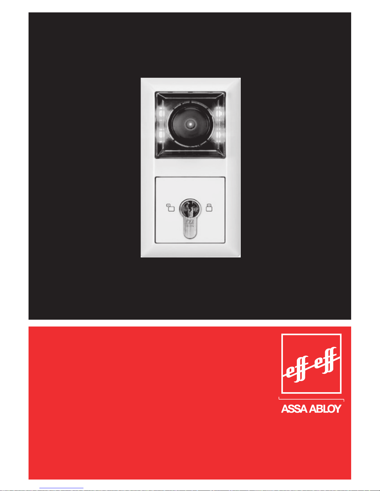
Escape Door Control
Terminal
Type 1385/1384
Page 2

ASSA ABLOY Sicherheitstechnik GmbH
Bildstockstrasse 20
72458 Albstadt Germany
Telephone: +49 (0)7431 123-0
Fax: +49 (0)7431 123-240
Internet: www.assaabloy.de
Email: [email protected]
D0055801
07.2010
V. 2.6
V. 3.8 and above
V. 3.8 and above
V. 2.0 and above
© 2010, ASSA ABLOY Sicherheitstechnik GmbH
This document and all its parts are copyrighted. Any use or changes outside the strict limits of the copyright are prohibited and liable to prosecution if no prior consent is obtained from
ASSA ABLOY Sicherheitstechnik GmbH.
This particularly applies to any copying, translations, microforms, or storing and processing in electronic systems.
Publisher:
Document
number:
Issue
date:
Firmware
FT Manager
FT-Server
901-20
Copyright:
Page 3

1
Content
Description . . . . . . . . . . . . . . . . . . . . . . . . . . . . . . . . . . . . . . . . . . . . . . . . . . . . . . . . . . . . 4
Innovation . . . . . . . . . . . . . . . . . . . . . . . . . . . . . . . . . . . . . . . . . . . . . . . . . . . . . . . . . . . . . . . . 4
Functions . . . . . . . . . . . . . . . . . . . . . . . . . . . . . . . . . . . . . . . . . . . . . . . . . . . . . . . . . . . . . . . . . 4
General . . . . . . . . . . . . . . . . . . . . . . . . . . . . . . . . . . . . . . . . . . . . . . . . . . . . . . . . . . . . . . . . . 6
Introduction . . . . . . . . . . . . . . . . . . . . . . . . . . . . . . . . . . . . . . . . . . . . . . . . . . . . . . . . . . . . . . 6
Symbols in these instructions. . . . . . . . . . . . . . . . . . . . . . . . . . . . . . . . . . . . . . . . . . . . . 6
Packaging and storage . . . . . . . . . . . . . . . . . . . . . . . . . . . . . . . . . . . . . . . . . . . . . . . . . . . . 7
Environmental protection . . . . . . . . . . . . . . . . . . . . . . . . . . . . . . . . . . . . . . . . . . . . . . . . 7
Intended use . . . . . . . . . . . . . . . . . . . . . . . . . . . . . . . . . . . . . . . . . . . . . . . . . . . . . . . . . . . . . . 7
Warranty . . . . . . . . . . . . . . . . . . . . . . . . . . . . . . . . . . . . . . . . . . . . . . . . . . . . . . . . . . . . . . . . . . 7
Installation. . . . . . . . . . . . . . . . . . . . . . . . . . . . . . . . . . . . . . . . . . . . . . . . . . . . . . . . . . . . . 8
Regulations . . . . . . . . . . . . . . . . . . . . . . . . . . . . . . . . . . . . . . . . . . . . . . . . . . . . . . . . . . . . . . . 8
Preparatory tasks. . . . . . . . . . . . . . . . . . . . . . . . . . . . . . . . . . . . . . . . . . . . . . . . . . . . . . . . . . 8
Providing power supply . . . . . . . . . . . . . . . . . . . . . . . . . . . . . . . . . . . . . . . . . . . . . . . . . . . 8
Selection of cabling . . . . . . . . . . . . . . . . . . . . . . . . . . . . . . . . . . . . . . . . . . . . . . . . . . . . . . . 9
Cabling . . . . . . . . . . . . . . . . . . . . . . . . . . . . . . . . . . . . . . . . . . . . . . . . . . . . . . . . . . . . . . . . . . . 9
Connecting the escape door module . . . . . . . . . . . . . . . . . . . . . . . . . . . . . . . . . . . .10
Connecting the key switch module . . . . . . . . . . . . . . . . . . . . . . . . . . . . . . . . . . . . . .10
Fitting the escape door control module . . . . . . . . . . . . . . . . . . . . . . . . . . . . . . . . .11
Replacing the profile half cylinder . . . . . . . . . . . . . . . . . . . . . . . . . . . . . . . . . . . . . . .12
Installation and connection . . . . . . . . . . . . . . . . . . . . . . . . . . . . . . . . . . . . . .13
View of circuit boards. . . . . . . . . . . . . . . . . . . . . . . . . . . . . . . . . . . . . . . . . . . . . . . . . . . .13
Individual escape door module
1385
. . . . . . . . . . . . . . . . . . . . . . . . . . . . . . . . . . .14
Individual escape door module
1384
. . . . . . . . . . . . . . . . . . . . . . . . . . . . . . . . . . .15
Individual key switch module . . . . . . . . . . . . . . . . . . . . . . . . . . . . . . . . . . . . . . . . . . . .16
Key switch module in parallel. . . . . . . . . . . . . . . . . . . . . . . . . . . . . . . . . . . . . . . . . . . .17
Key switch module Individual 1380E04. . . . . . . . . . . . . . . . . . . . . . . . . . . . . . . . . .18
Key switch module 1380E04 in parallel. . . . . . . . . . . . . . . . . . . . . . . . . . . . . . . . . .19
Locking elements . . . . . . . . . . . . . . . . . . . . . . . . . . . . . . . . . . . . . . . . . . . . . . . . . . . . . . . .20
Adapter circuit board 1385EAP . . . . . . . . . . . . . . . . . . . . . . . . . . . . . . . . . . . . . . . . . .20
I/O Extension Module 901-20. . . . . . . . . . . . . . . . . . . . . . . . . . . . . . . . . . . . . . . . . . . .21
Terminal assignments 901-20. . . . . . . . . . . . . . . . . . . . . . . . . . . . . . . . . . . . . . . . . . . .23
Wire-interconnected interlock (
1385
). . . . . . . . . . . . . . . . . . . . . . . . . . . . . . . . . .25
Page 4

2
Set-up operation . . . . . . . . . . . . . . . . . . . . . . . . . . . . . . . . . . . . . . . . . . . . . . . . . . . .28
General. . . . . . . . . . . . . . . . . . . . . . . . . . . . . . . . . . . . . . . . . . . . . . . . . . . . . . . . . . . . . . . . . . .28
Switching on or return of power supply . . . . . . . . . . . . . . . . . . . . . . . . . . . . . . . . .28
Operation . . . . . . . . . . . . . . . . . . . . . . . . . . . . . . . . . . . . . . . . . . . . . . . . . . . . . . . . . . . . .29
Explanation of symbols . . . . . . . . . . . . . . . . . . . . . . . . . . . . . . . . . . . . . . . . . . . . . . . . . .29
Temporary-release . . . . . . . . . . . . . . . . . . . . . . . . . . . . . . . . . . . . . . . . . . . . . . . . . . . . . . .29
Pre-alarm . . . . . . . . . . . . . . . . . . . . . . . . . . . . . . . . . . . . . . . . . . . . . . . . . . . . . . . . . . . . . . . .30
Permanent release . . . . . . . . . . . . . . . . . . . . . . . . . . . . . . . . . . . . . . . . . . . . . . . . . . . . . . .30
Locking . . . . . . . . . . . . . . . . . . . . . . . . . . . . . . . . . . . . . . . . . . . . . . . . . . . . . . . . . . . . . . . . . .31
Danger alarm . . . . . . . . . . . . . . . . . . . . . . . . . . . . . . . . . . . . . . . . . . . . . . . . . . . . . . . . . . . .31
Tamper alarm . . . . . . . . . . . . . . . . . . . . . . . . . . . . . . . . . . . . . . . . . . . . . . . . . . . . . . . . . . . .32
Multiple alarm . . . . . . . . . . . . . . . . . . . . . . . . . . . . . . . . . . . . . . . . . . . . . . . . . . . . . . . . . . .33
Configuration . . . . . . . . . . . . . . . . . . . . . . . . . . . . . . . . . . . . . . . . . . . . . . . . . . . . . . . .34
General. . . . . . . . . . . . . . . . . . . . . . . . . . . . . . . . . . . . . . . . . . . . . . . . . . . . . . . . . . . . . . . . . . .34
Explanation of symbols . . . . . . . . . . . . . . . . . . . . . . . . . . . . . . . . . . . . . . . . . . . . . . . . . .34
Starting configuration mode. . . . . . . . . . . . . . . . . . . . . . . . . . . . . . . . . . . . . . . . . . . . .35
Advancing through menu items . . . . . . . . . . . . . . . . . . . . . . . . . . . . . . . . . . . . . . . . .36
Defining settings in the menu . . . . . . . . . . . . . . . . . . . . . . . . . . . . . . . . . . . . . . . . . . .36
Menu structure . . . . . . . . . . . . . . . . . . . . . . . . . . . . . . . . . . . . . . . . . . . . . . . . . . . . . . . . . .37
Starting configuration mode. . . . . . . . . . . . . . . . . . . . . . . . . . . . . . . . . . . . . . . . . . . . .38
Configuration mode switched on. . . . . . . . . . . . . . . . . . . . . . . . . . . . . . . . . . . . . . . .38
1 - Profile. . . . . . . . . . . . . . . . . . . . . . . . . . . . . . . . . . . . . . . . . . . . . . . . . . . . . . . . . . . . . . . . .38
2 - Temporary release time. . . . . . . . . . . . . . . . . . . . . . . . . . . . . . . . . . . . . . . . . . . . . . .38
3 - Door monitoring time . . . . . . . . . . . . . . . . . . . . . . . . . . . . . . . . . . . . . . . . . . . . . . . .38
4 - Pre-alarm time. . . . . . . . . . . . . . . . . . . . . . . . . . . . . . . . . . . . . . . . . . . . . . . . . . . . . . . .39
5 - Alarm time. . . . . . . . . . . . . . . . . . . . . . . . . . . . . . . . . . . . . . . . . . . . . . . . . . . . . . . . . . . .39
6 - Duration orientation signal. . . . . . . . . . . . . . . . . . . . . . . . . . . . . . . . . . . . . . . . . . .39
7 - Activation delay. . . . . . . . . . . . . . . . . . . . . . . . . . . . . . . . . . . . . . . . . . . . . . . . . . . . . . .39
8 - Alarm tones. . . . . . . . . . . . . . . . . . . . . . . . . . . . . . . . . . . . . . . . . . . . . . . . . . . . . . . . . . .40
9 - Request TSB address. . . . . . . . . . . . . . . . . . . . . . . . . . . . . . . . . . . . . . . . . . . . . . . . . .40
10 - Master/Slave. . . . . . . . . . . . . . . . . . . . . . . . . . . . . . . . . . . . . . . . . . . . . . . . . . . . . . . . .40
11 - Display TSB address . . . . . . . . . . . . . . . . . . . . . . . . . . . . . . . . . . . . . . . . . . . . . . . . .41
12 - Re-set to factory settings. . . . . . . . . . . . . . . . . . . . . . . . . . . . . . . . . . . . . . . . . . . .41
13 - End configuration mode . . . . . . . . . . . . . . . . . . . . . . . . . . . . . . . . . . . . . . . . . . . .41
Page 5

3
Configuration mode switched on. . . . . . . . . . . . . . . . . . . . . . . . . . . . . . . . . . . . . . . .41
1 - Profile. . . . . . . . . . . . . . . . . . . . . . . . . . . . . . . . . . . . . . . . . . . . . . . . . . . . . . . . . . . . . . . . .41
Ending configuration mode. . . . . . . . . . . . . . . . . . . . . . . . . . . . . . . . . . . . . . . . . . . . . .42
Automatic change from configuration mode. . . . . . . . . . . . . . . . . . . . . . . . . . . .43
Profile settings . . . . . . . . . . . . . . . . . . . . . . . . . . . . . . . . . . . . . . . . . . . . . . . . . . . . . . . . . . .44
Master/Slave . . . . . . . . . . . . . . . . . . . . . . . . . . . . . . . . . . . . . . . . . . . . . . . . . . . . . . . . . . . . .46
Display TSB address . . . . . . . . . . . . . . . . . . . . . . . . . . . . . . . . . . . . . . . . . . . . . . . . . . . . . .48
Example configuration . . . . . . . . . . . . . . . . . . . . . . . . . . . . . . . . . . . . . . . . . . . . . . . . . . .49
Special function
1385
- networked . . . . . . . . . . . . . . . . . . . . . . . . . . . . . . . . . . . . .50
Check list - Testing before initial operation . . . . . . . . . . . . . . . . . .54
Components . . . . . . . . . . . . . . . . . . . . . . . . . . . . . . . . . . . . . . . . . . . . . . . . . . . . . . . . . . . . .54
Installation . . . . . . . . . . . . . . . . . . . . . . . . . . . . . . . . . . . . . . . . . . . . . . . . . . . . . . . . . . . . . . .54
Function . . . . . . . . . . . . . . . . . . . . . . . . . . . . . . . . . . . . . . . . . . . . . . . . . . . . . . . . . . . . . . . . .55
Maintenance . . . . . . . . . . . . . . . . . . . . . . . . . . . . . . . . . . . . . . . . . . . . . . . . . . . . . . . . .59
Annual inspection. . . . . . . . . . . . . . . . . . . . . . . . . . . . . . . . . . . . . . . . . . . . . . . . . . . . . . . .59
Maintenance . . . . . . . . . . . . . . . . . . . . . . . . . . . . . . . . . . . . . . . . . . . . . . . . . . . . . . . . . . . . .59
Alarm signals . . . . . . . . . . . . . . . . . . . . . . . . . . . . . . . . . . . . . . . . . . . . . . . . . . . . . . . . .60
Identification of alarm criteria. . . . . . . . . . . . . . . . . . . . . . . . . . . . . . . . . . . . . . . . . . .60
Identification of the cause of the alarm . . . . . . . . . . . . . . . . . . . . . . . . . . . . . . . . . .61
Technical Specifications. . . . . . . . . . . . . . . . . . . . . . . . . . . . . . . . . . . . . . . . . . .62
Escape door module . . . . . . . . . . . . . . . . . . . . . . . . . . . . . . . . . . . . . . . . . . . . . . . . . . . . .62
Key switch module. . . . . . . . . . . . . . . . . . . . . . . . . . . . . . . . . . . . . . . . . . . . . . . . . . . . . . .63
Profile half cylinder . . . . . . . . . . . . . . . . . . . . . . . . . . . . . . . . . . . . . . . . . . . . . . . . . . . . . .63
Page 6

4
Description
In developing the new generation of FT, particular importance was attached to:
• Forward-thinking innovation
• Versatile range of uses
• Operational and functional elements integrated into a compact design
• Wide range of functions due to networking of devices
• Options for integration into building and alarm management systems
• High operational reliability
• Less time and effort to install and configure the system
• Use of standard switch boxes
Overview
• Escape door unlocked using integrated emergency button
• Escape door unlocked externally, by a fire alarm system, for instance
• Permanent release using internal key pushbutton or an external contact, such as a timer switch
• Temporary release using internal key pushbutton or externally connected pushbutton
• Escape door locking status signalled by door status indicator
• Alarm status indicated by an optical and audible signal
Device
1384
(offline version)
• A simplified individual stand-alone system not integrated into the
building network
Innovation
Functions
Networked application
Simplified individual
stand-alone system
Complex door opening solutions
Individual stand-alone system
1384
1385
Page 7

5
• Set-up operation and configuration using a key switch
• Cannot be extended
Device
1385
(stand-alone function)
• Set-up operation and configuration using a key switch
• Can be extended with E/A Module 901-20
• Implementation of a wire-interconnected interlock function.
Device
1385
(networked)
• Set-up operation and configuration using
FT‑Manager.
• Can be configured using a key switch
• Can be extended with E/A Module 901-20
• Up to 120 devices can be connected to the TSB Controller
• Delayed release after EMERGENCY-OPEN is activated (special function)
Page 8
6
General
ASSA ABLOY Sicherheitstechnik GmbH's extensive experience, and
state-of-the-art production and testing procedures ensure the device is
highly reliable.
These fitting and installation instructions have been compiled for skilled
electricians and trained personnel. They are designed to enable you to
install and operate the device safely, and fully exploit the permitted range
of uses the control terminal has to offer.
It also provides information regarding how key components work.
Note
These instructions describe both device types
1384
and
1385
with indi-
vidual differing characteristics indicated where required.
The symbols in these operating instructions are designed to help you use
the devices and instructions quickly and safely.
Note
This symbol indicates additional information which is useful when handling devices.
Warning about a general hazard
This warning symbol indicates tasks where different causes may lead to
hazards or impair device functions.
Steps in procedures
The specified sequence of steps will make it easier for you to use the
device safely and correctly.
Result
This indicates where the end result of a sequence of steps is described.
Introduction
Symbols
in these
instructions
!
Page 9

7
Our devices are carefully packed to ensure adequate protection during
shipment.
When you receive your device, you must check the device and its packaging to ensure it is complete and undamaged.
Risk of injury
The device must not be used if it is damaged.
Damaged cables and connector assemblies also represent a safety hazard
and must not be used.
Packaging materials must be recycled. Local environmental protection
regulations must be complied with.
The device is designed to provide an escape door control system. It can
be operated as a stand-alone control unit or within a building network
(
1385
only). It is not intended for any other type of use.
Note
Device
1384
is designed as an offline unit and cannot be extended.
Device
1385
can be used as a stand-alone or networked unit. An E/A
extension module can be connected in stand-alone mode.
We provide a warranty for this device valid from the date of purchase in
accordance with statutory/country-specific regulations. If any damage is
incurred, the unit will be repaired or a replacement supplied.
Any damage caused through natural wear, overloading or incorrect use
are excluded from the warranty.
Packaging and
storage
!
Environmental
protection
Intended use
Warranty
Page 10
8
Installation
• In accordance with 'Guidelines for electronic locking systems in escape
route doors', the escape door control module must be positioned
in such a way that the emergency pushbutton is placed between
850 mm and 1200 mm above the finished floor level (FFL). Further
regulatory requirements can be found in respective local building
ordinances.
• German Electrical Engineering Association (VDE) and local electricity
company regulations must be observed.
• It must be possible to disconnect the device from the power supply
circuit using an easily accessible energy-isolation device.
• Electric locking systems can only be used on smoke or fire doors if
the door's product use certification states such systems can be used.
Systems must be installed as required by the certification. Exception:
Elements which may also be fitted to ready manufactured fire protection barriers.
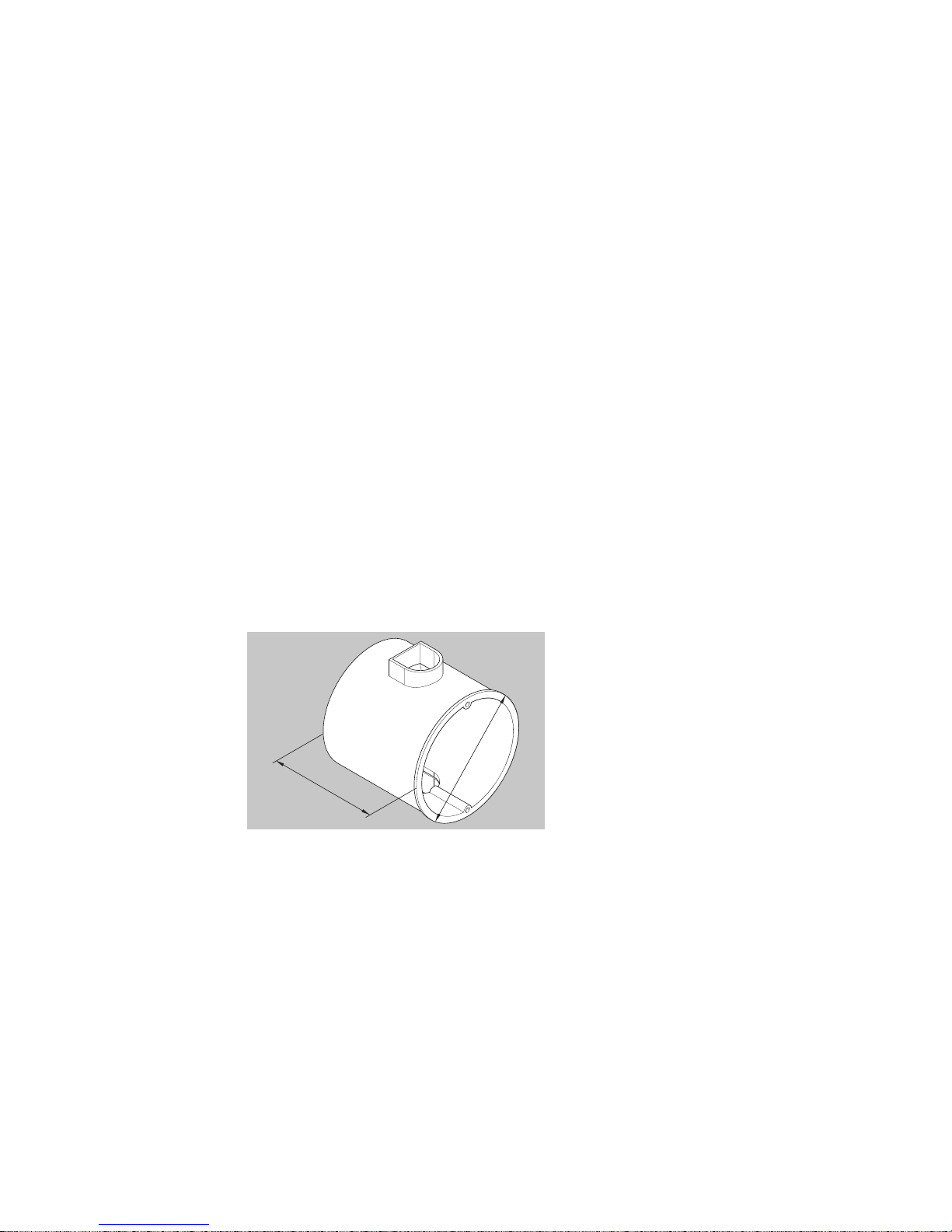
>62,5
60
The escape door and key switch
module is installed in standard
flush-mounted switch boxes.
Install standard flush-
mounted boxes according to
requirements.
A low safety voltage between +12V -15% and +24V +15% must be supplied to operate the device in accordance with DIN 60 950. You should
ideally use Power Supply Unit Type 1003FT-24-05, which is suitable for
use with a standard switch box (see separate fitting and installation
instructions). The required power supply can then be fed directly from
this unit.
Regulations
Preparatory
tasks
Providing
power supply
Page 11

9
Control circuits
Description Size
Length max. 300 m
Length of cabling to locking unit max. 100 m
Cable cross-section Choose a cable which will ensure
the voltage in the locking unit
stands at a maximum of 10%
under the locking unit's specified
rated operating voltage when
it is working to full capacity and
while taking into account all other
losses such as potential voltage
drop in the feed cable.
TS bus lines (
1385
)
Description Size
Length max. 1,000 m
Resistance to bus devices max. 65 Ω
Special considerations Use separate line
Type JY (St) Y
Cable cross-section Min. 0.28 mm²
Ideally 0.5 mm²
Only use one wire in each line
Do not connect wires in parallel
Supply lines must be:
• fed through holes in the flush-mounted switch boxes
• fed and secured behind or next to the modules
Selection of
cabling
Cabling
Page 12
10
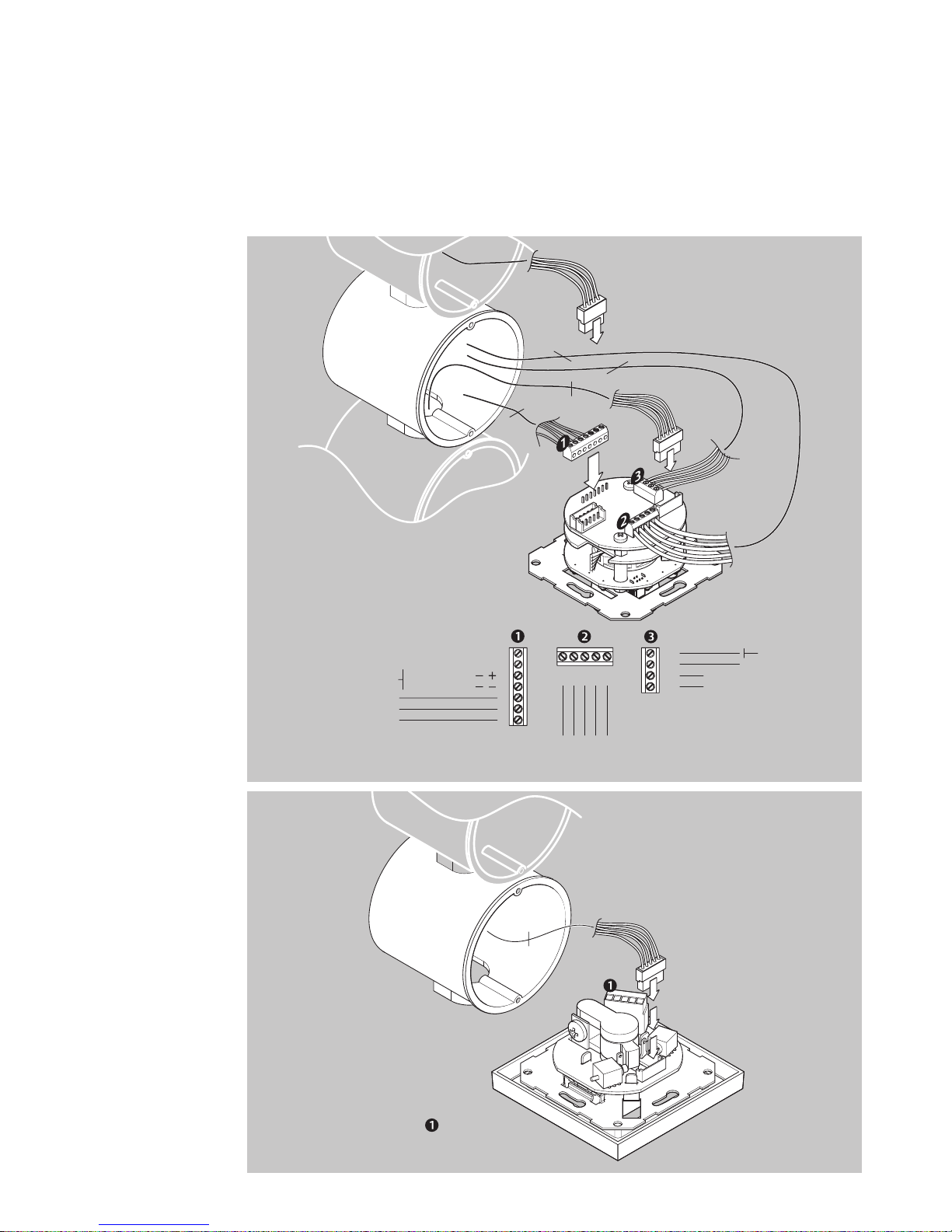
Connecting the
escape door
module
SYSCON5
1385EVL5
To
locking elements
SYSCON5
SYSCON
4
(optional
from power unit)
SYSCON4
13
14
15
16
Universal input
TS-Bus
Data
8 109 1211
A DB FE
5
4
5
7
12 - 24 V DC
+15%; -10%
NC
C
NO
Potential-free
Or via SYSCON4
relay contact
30 V/1 A
5
6
7
4
3
2
1
See instruction
D0047000
Connecting
the key switch
module
SYSCON5
1385EVL5
Connection
external operating unit
(optional)
5
Page 13
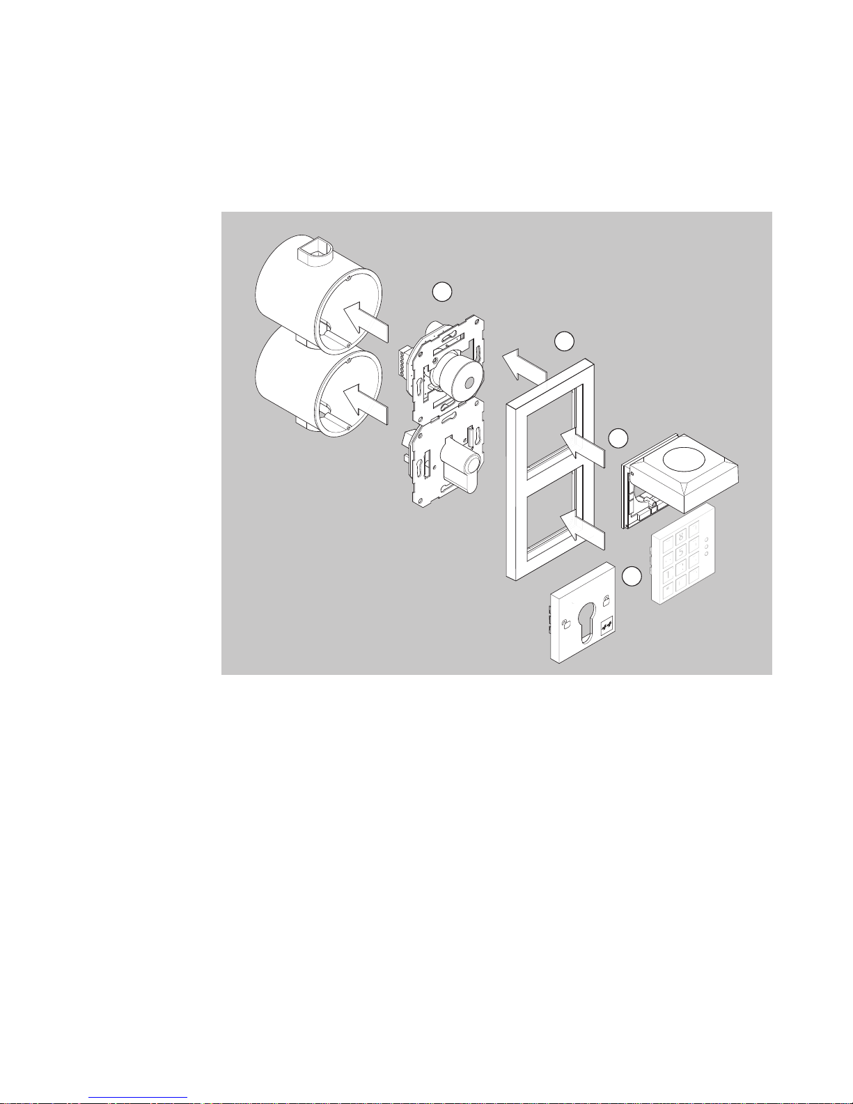
11
Install all components as indicated in the diagrams.
Fitting the
escape door
control module
7 8 9
4 5 6
1 2 3
* 0 #
1
2
3
4
Page 14
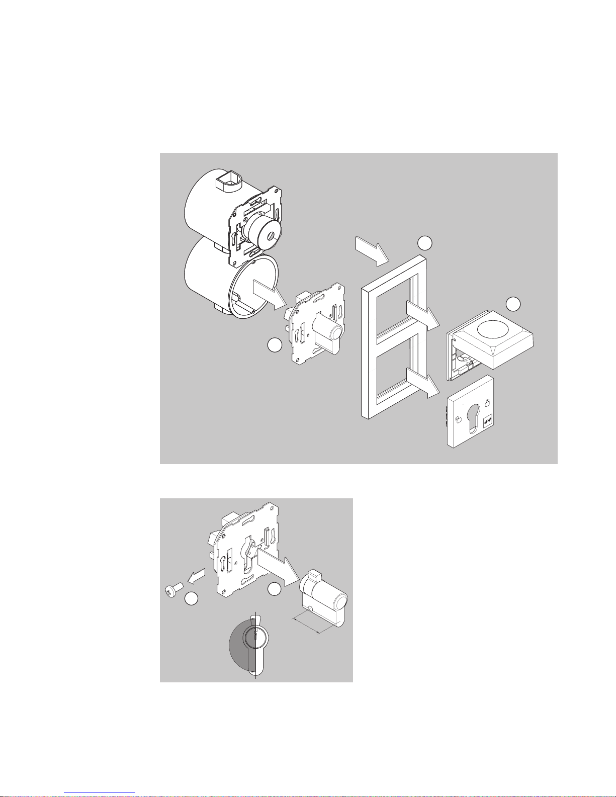
12
Disassemble all components as indicated in the diagrams.
30,5
4
5
180°
Undo the cross-head screw
which fastens the profile half
cylinder.
Take out profile half cylinder
through the front and replace
with a suitable new cylinder.
Fasten cylinder with cross-head
screw.
Check locking lever settings
(both pushbuttons must be
activated).
Re-install all components and carry out a functions check.
Replacing the
profile half
cylinder
1
2
3
Page 15
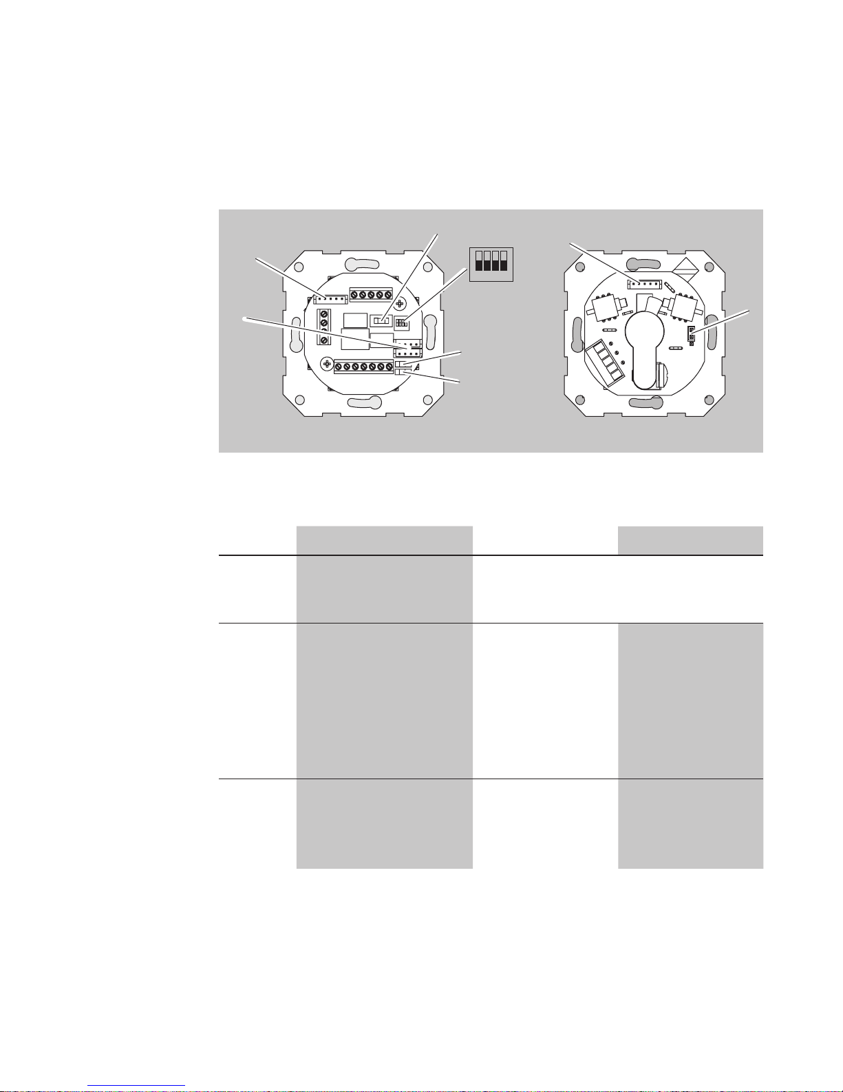
13
Installation and connection
DIP1
All switches set to the OFF position by default in the factory
Switch Function OFF ON
1
2
Hi-O: Bus termination
Hi-O: Group
No function assigned:
Reserved for extension at a later date
3 TS bus: Master/Slave
(
1385
)
Slave
(For standalone operation
without E/A
extension
and networked
operation)
Master with
address 1 *
)
(For stand-alone
operation with
E/A extension)
4 Configuration mode
(set according to
hardware if no key
switch is being used)
OFF ON
*) If an E/A extension is used, this must be assigned to address'2'.
View of circuit
boards
5 6 74321
8 109 1211
16
15
14
13
SYSCON5
F1
DIP1
OFF
1 2 3 4
JP1
LB1
LB2
SYSCON5
3
2
1
54321
2 x
SYSCON4
Escape door module Key switch module
Page 16
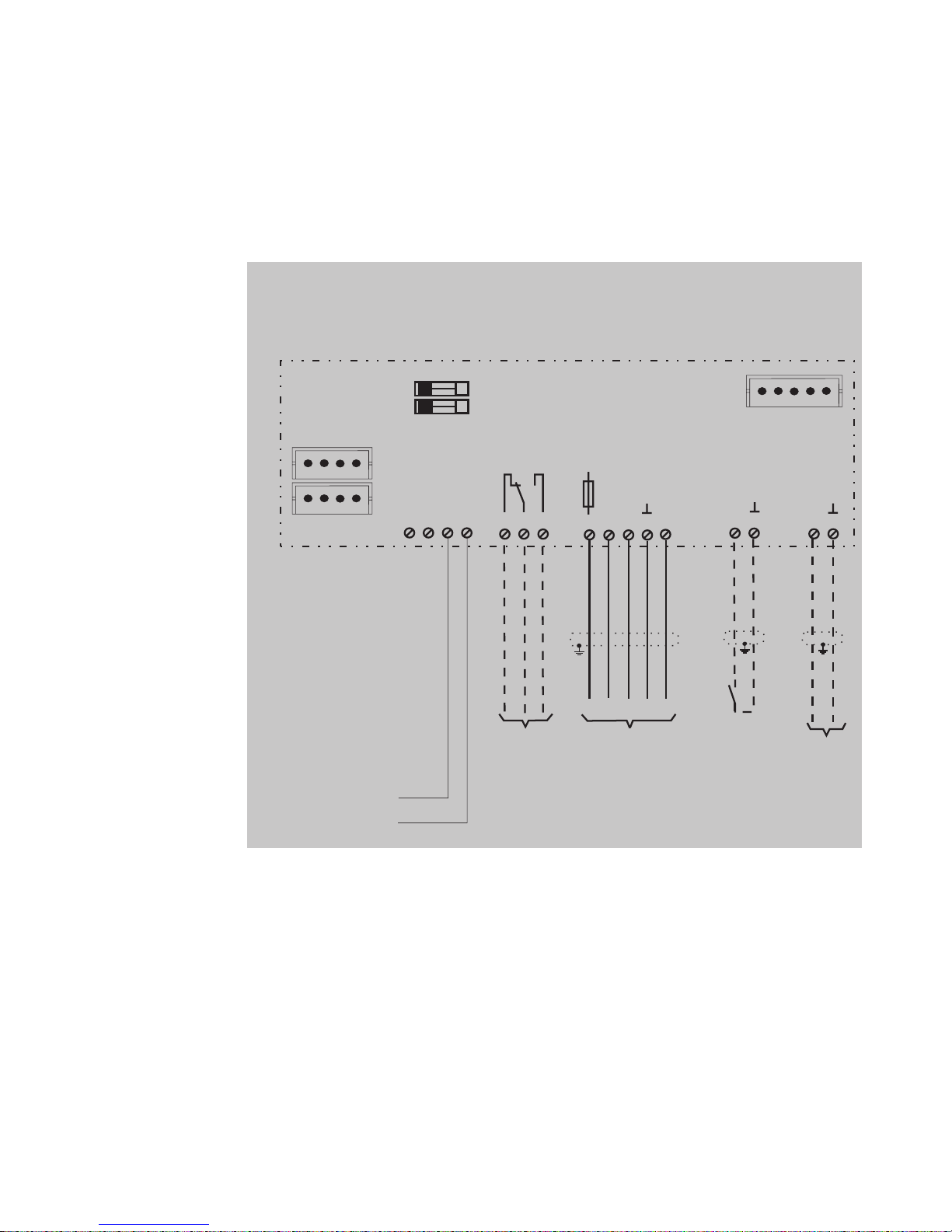
14
Circuit diagram
1)
Connections have different functions depending on the configuration
(see the 'Configuration' section).
Individual
escape door
module
1385
F1
Littelfuse
154001
1AF
2
1
3
4
567
8
9
11
12
10
13
14
15
16
A B ED F
S
Data
LB1
LB2
Connection of the
respective locking
element
SYSCON-5
SYSCON-4
Jumper LB1/LB2
max. 24V / 1A
TS-Bus
Potential-free
relay contact
1)
Universalinput
1)
+
-
See instruction D00470..
5-pin connector system for
connection of the key switch
type 1385ES1 or
additional components
2 x 4-pin connector system
for connection of the
power unit type
1003FT-24-05 and/or
additional components
Voltage supply
external power unit
12 - 24 VDC +15%/ - 10%
according DIN/EN 60950
Page 17
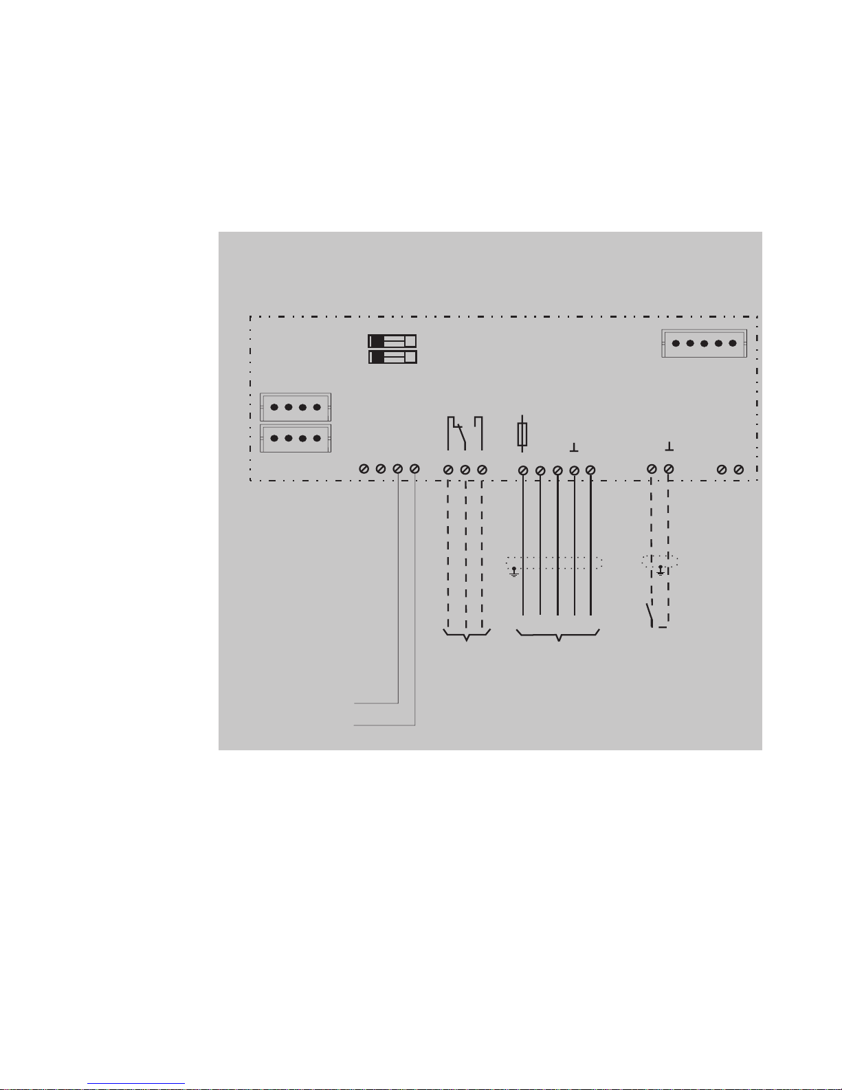
15
Circuit diagram
1)
Connections have different functions depending on the configuration
(see the 'Configuration' section).
Individual
escape door
module
1384
F1
Littelfuse
154001
1AF
2
1
3
4
567
8
9
11
12
10
13
14
15
16
A B ED F
S
LB1
LB2
SYSCON-5
SYSCON-4
max. 24V / 1A
+
-
Connection of the
respective locking
element
Jumper LB1/LB2
Potential-free
relay contact
1)
Universalinput
1)
See instruction D00470..
5-pin connector system for
connection of the key switch
type 1385ES1 or
additional components
2 x 4-pin connector system
for connection of the
power unit type
1003FT-24-05 and/or
additional components
Voltage supply
external power unit
12 - 24 VDC +15%/ - 10%
according DIN/EN 60950
Page 18
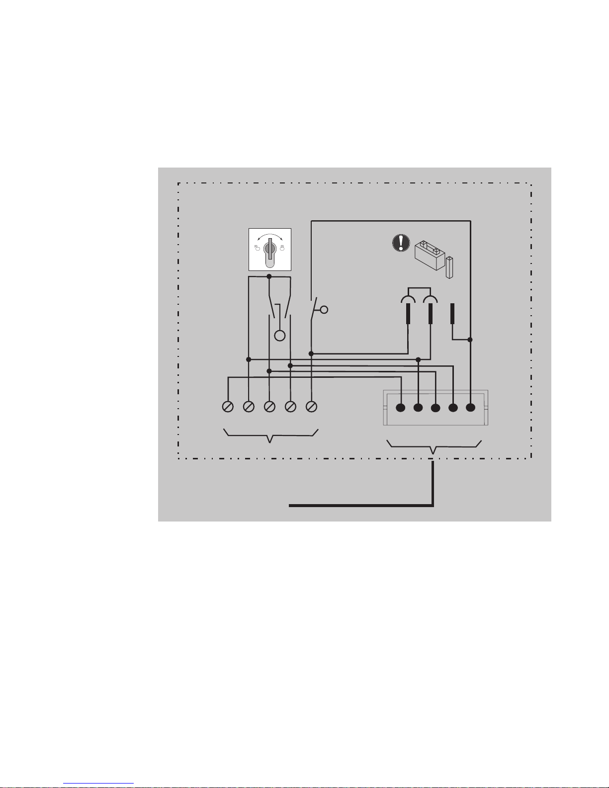
16
Circuit diagram
Individual key
switch module
SYSCON-5
Max.
12 V/100 mA
112
2
3
3
4
5
L
R
1385EVL5
Sabotage
Tamper
JP1
1
3
2
Page 19
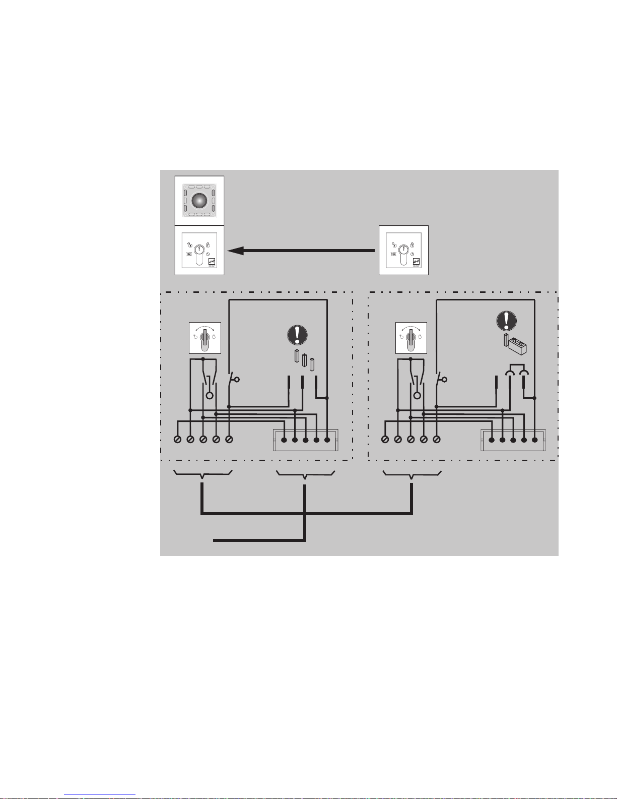
17
Circuit diagram
Key switch
module in
parallel
SYSCON-5
112
2
3
3
4
5
L
R
SYSCON-5
112
2
3
3
4
5
L
R
1 32
1 32
Max.
12 V/100 mA
1385EVL5
Sabotage
Tamper
JP1
Max.
12 V/100 mA
Sabotage
Tamper
JP1
Page 20
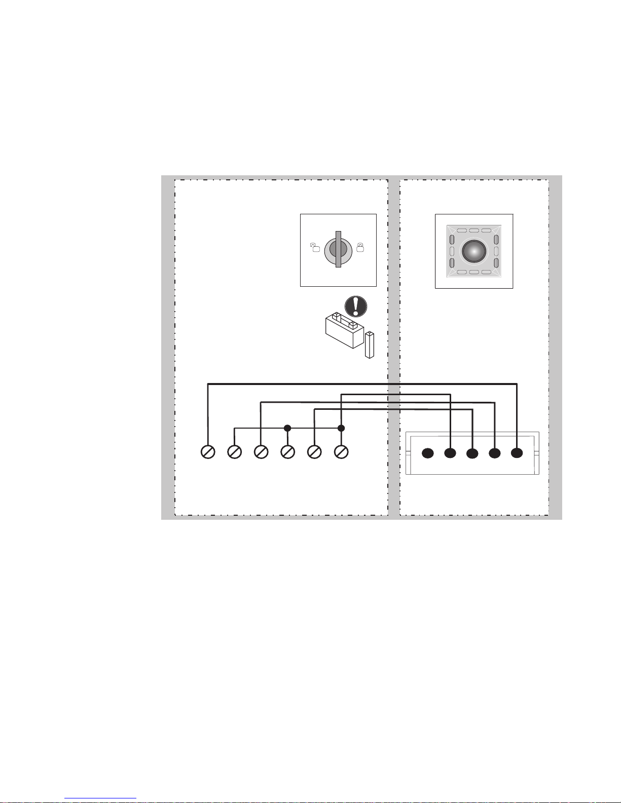
18
Circuit diagram
Key switch
module Indi- Indi-Individual 1380E04
SYSCON-5
9 10
11
12
13 14
1 2
3
4
5
1380E04 Escape door module
1
3
2
Page 21
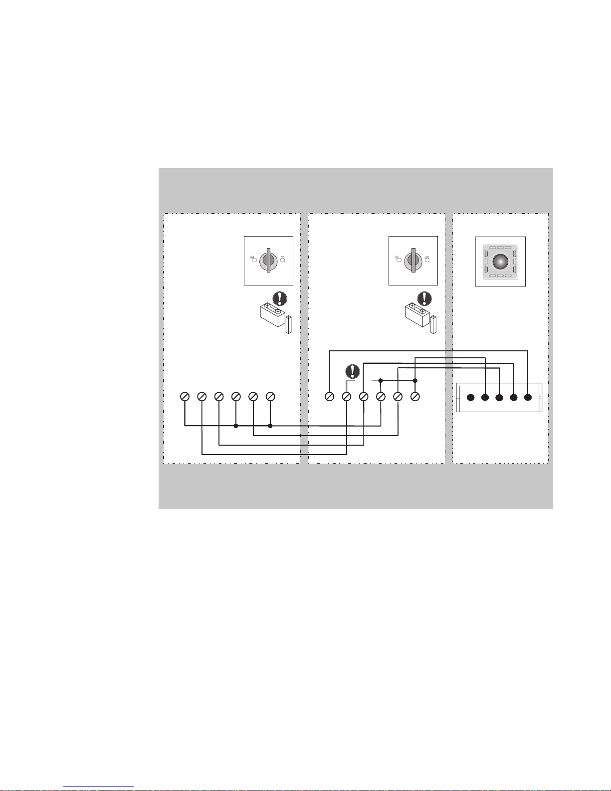
19
Circuit diagram
Key switch
module
1380E04 in
parallel
SYSCON-5
9
Remove
Bridge 10 - 12
10
11 1213 14
1 2
3
4
5
1380E04
1
3
2
9 10
11 1213 14
1380E04
1
3
2
Escape door module
Page 22
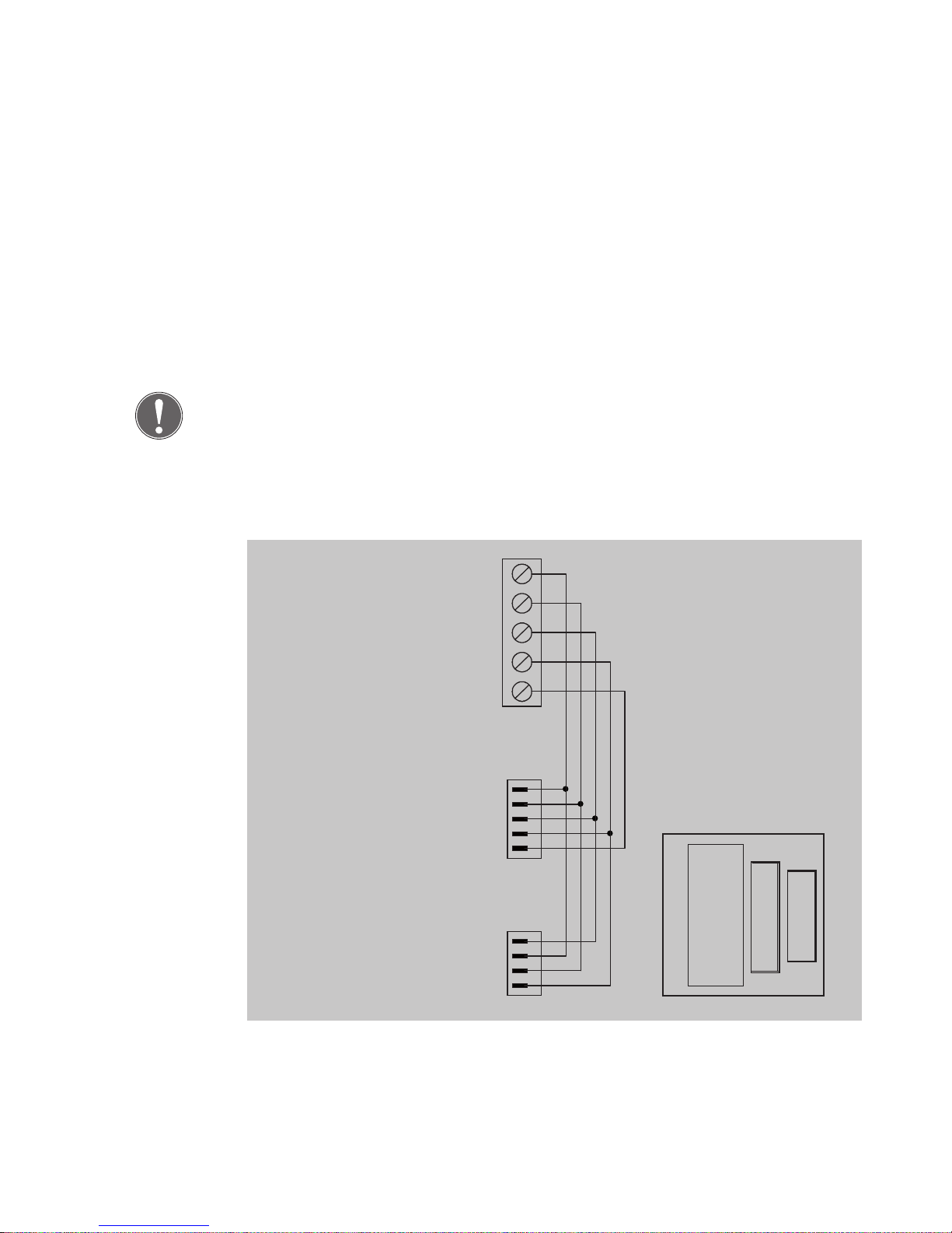
20
For circuit diagrams, see Instructions D0047000.
Connection of connecting line SYSCON4 or SYSCON5 to permanent
wiring.
Note
Do not use SYSCON4 and SYSCON5 together at the same time.
An external switch contact (control element) is connected in accordance
with the use specifications table.
Circuit diagram
Locking
elements
Adapter circuit
board 1385EAP
1
2
3
4
5
1
2
3
4
5
1
2
3
4
5
1
2
3
4
5-pin
Connecting terminal
5-pin type 086 RIA
Set up of platine
SYSCON5
SYSCON5
SYSCON4
SYSCON4
Page 23
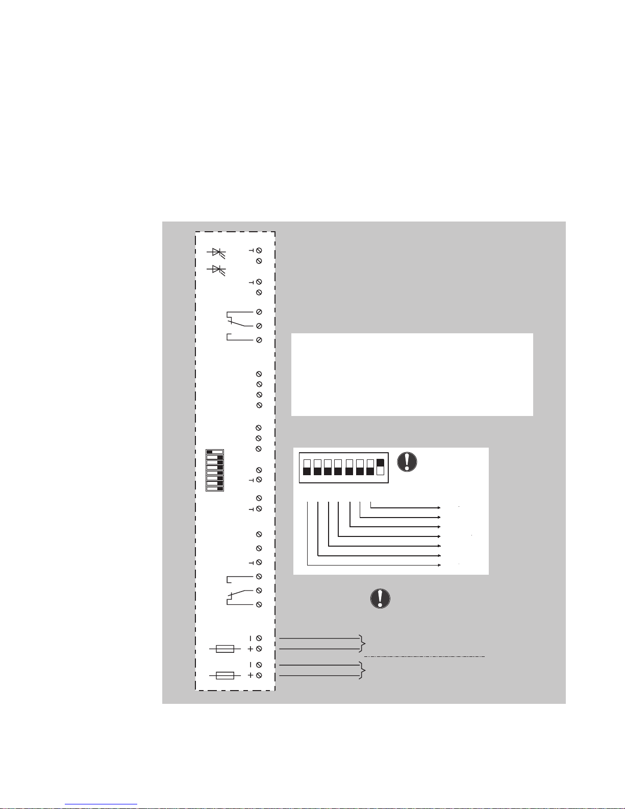
21
Device
1385
can be extended with E/A Extension Module 901-20 to
include further switching operations.
Circuit diagram
I/O Extension
Module
901-20
1 2
3
4
5 6
7
8 9 10
11 12
13
14
15 16
17
18 19 20
21 22
23
24
25 26
27
28
1 2 3 4 5 6 7 8
ON
OFF
F1
0,5AT
F2
0,5AT
K2
Potential-free relay contact
Load capability max. 24V / 2A
Potential-free relay contact
Load capability max. 24V / 2A
Code switch for the adjusting
of the Bus-Adress of the unit
K1
D
LED
green
LED
yellow
E1 E2
E3 E4
E5 E6
E7
E8
A1 A2
A3
A4
12 V battery or12 V DC, controlled
12 V DC ±10 %, residual ripple max. 50 %
12 V AC ±10 %
Only at terminal 1 and 2: 24 V DC, controlled
ON
1 2 3
4 567
8
2
0
2122232
4
2
5
2
6
64
32
16
8
4
2
1
Switch 8 has to be
in the ON position.
Power supply
E1-E8 = Inputs/ Signal = Low Active (0V)
A1-A4 = Outputs - Open Collector / mass switching (0V)
(Note voltage drop!)
K1 = Potential-free relay output
Load capability max. 24V / 2A (resistive load)
K2 = Potential-free relay output
Load capability: max. 24V / 2A (resistive load)
Note:
Connect only one power
supply
Page 24
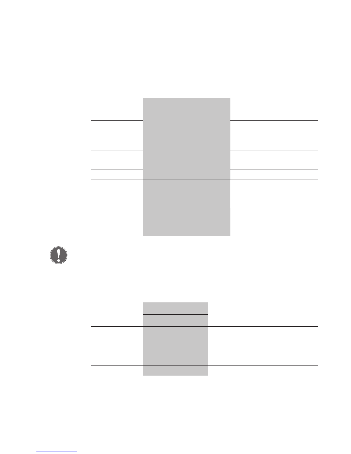
22
Configuration using the
1385
DIP switch networked stand-alone
1 Address off
2 on
3
Profile number
4
5 off
6 off
7 off
8 Networked operating
mode
= on
Stand-alone operating
mode
= off
Note: A TS bus controller is
required.
The
1385
must be set to
master operation (
1385
:
DIP 3 = on)
Note
If configuration is carried out using
FT Manager
, always select Profile '0'
(called functions templates in
FT Manager
) as it is the only place where
changes can be saved.
Profiles when using the
1385
(stand-alone)
Profile DIP switch Function
3 4
0 off off Link to higher level systems (fac-
tory setting)
1 off on Door operator
2 on off Door control
3 on on Interlock
Page 25

23
Profile 0 - Link to higher level systems
Connections Description Connections Description
E1 Fire detector system
(inverse)
K1 Released/locked
signal
E2 Burglar alarm
system/Interlock
K2 Alarm signal
(inverse)
E3 Clock A1 E4 Lock A2 E5 Release A3 E6 Release with delay A4 E7 Temporary release
E8 -
Profile 1 - Door drive
Connections Description Connections Description
E1 Fire detector system
(inverse)
K1 Door operator - Au-
tomatic operation
E2 Burglar alarm
system/Interlock
K2 Door operator
- Activation
E3 Clock A1 E4 Lock A2 E5 Release A3 E6 Release with delay A4 E7 Temporary release
E8 -
Terminal assignments
901-20
Page 26

24
Profile 2 - Door drive
Connections Description Connections Description
E1 Fire detector system
(inverse)
K1 Electric door strike/
Motorized lock
E2 Burglar alarm
system/Interlock
K2 Holding magnet
E3 Clock A1 E4 Lock A2 E5 Release A3 E6 Release with delay A4 E7 Temporary release
E8 -
Profile 3 - Interlock
Connections Description Connections Description
E1 Fire detector system
(inverse)
K1 Door is interlocked
E2 Burglar alarm
system/Interlock
K2 Door is closed and
locked
(inverse)
E3 A1 Block interlock
E4 A2
E5 A3
E6 A4
E7
E8
Page 27
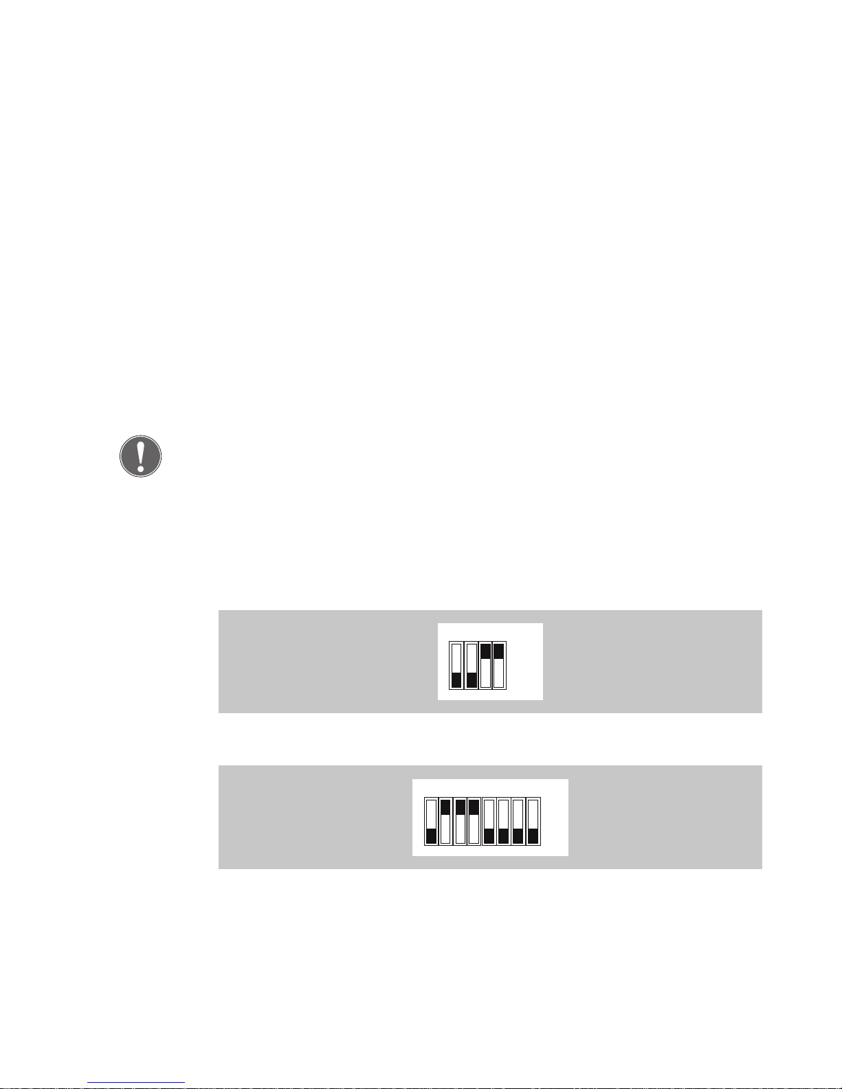
25
This is a basic interlock door system with an emergency exit function but
without a central bus master (stand-alone).
Function
As soon as a door is temporarily released or disengaged, the corresponding opposite door (several doors also possible) is blocked and thus cannot be opened.
If the disengaged door is not opened before the pre-set temporary release interval has elapsed, it is automatically locked again.
Note
The escape route is assured using a fail-unlocked system, i.e. in the event
of a power failure, or unlocking by a fire alarm system or an EMERGENCYOPEN switch, locking elements are disengaged and all doors can be
opened at the same time.
Pre-requirements:
• Device
1385
in stand-alone mode (DIP switch 3 = ON)
• E/A Extension Modules 901-20 with pre-set Profile '3' (also see 'Terminal assignments 901-20, Profile '3')
Wire-interconnected interlock (
1385
)
1 2 3 4
ON
OFF
1 2 3 4 5 6 7 8
ON
OFF
Page 28
26
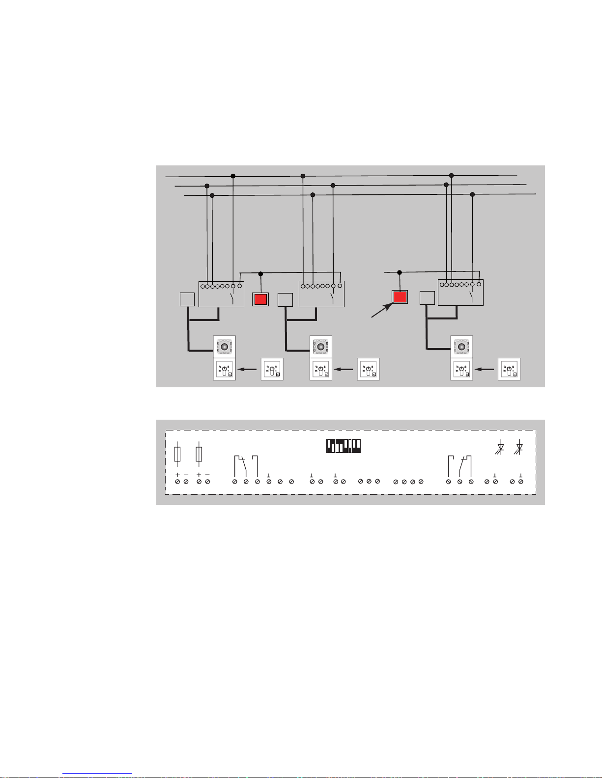
Circuit diagram overview
Terminal assignments 901-20
Output functions (A1 to A4)
• Block interlock. The corresponding opposite door(s) is/are blocked.
Output function K1 and K2
• 'Door blocked' and 'Door closed and locked' indicator displays.
Input function E1
• Emergency release (for opening interlock in the event of a failure).
The door is released in emergency mode and a corresponding alarm is
triggered.
Input functions (E2 to E8)
• Block door.
I/O
block door
ZF
I/O
I/O
I/O
block door
ZF
I/O
block door
ZF
I/O
Emergency
opening
8
1 234
5 6
7
8 9 10
11 121314
15 161718 19 20
21 222324
25 262728
1 234567
ON
OFF
F1
0,5ATF20,5AT
K2
K1
D
LED
green
LED
yellow
E1 E2
E3 E4
E5 E6
E7
E8
A1 A2
A3
A4
Page 29
27
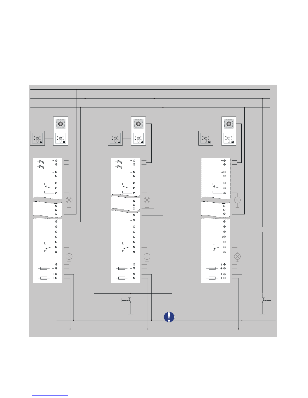
Detailed circuit diagram (example of use)
3
4
8 10 16
17 24
+
25 26
F1
0,5AT
F2
0,5AT
K2
K1
D
E1 E2
A1 A2
A3
A4
3
4
5 8 10 16
17 24
25 26
F1
0,5AT
F2
0,5AT
K2
K1
D
E1
11
E3E2
A1 A2
A3
A4
1 2
3
4
5
6
7
6
7
6
gn
rd
5
7
8
9
10
15
16
17
22
23
24
25 26
27
28
1 2
9 1512
22
23
27
28
1 2
9 15
22
23
27
28
F1
0,5AT
F2
0,5AT
K2
Pot. free
max. 24V / 2A
Pot. free
max. 24V / 2A
Pot. free
max. 24V / 2A
Pot. free
max. 24V / 2A
Pot. free
max. 24V / 2A
Pot. free
max. 24V / 2A
K1
D
E1 E2
A1 A2
A3
A4
+
gn
rd
Emergency opening
+
gn
rd
+
+ +
24 V DC
±10 %
-
+
Emergency
opening
Put all I-/O-units to
common ground
Page 30

28
Set-up operation
Note
The installation and operation of electric locking devices on doors on
emergency exit routes are subject to building authority regulations. Compliance must be ensured by both the fitter and the building operator.
Before the initial set-up operation:
Check all elements, including those which disengage the locking de-
vice and its electrical connections, to ensure they have been installed
and function according to regulations.
Have correct installation and operational capability of the escape door
locking device checked by technical specialists.
Install '
FT‑Manager
' software and check correct functioning (
1385
- networked only).
When the system is turned on or there is a failure in the power supply,
the position of the internal emergency switch and the status of all control
inputs are queried and evaluated. The resultant system switching status is
then directly dependent on these input parameters.
If an alarm is triggered after the system is switched on and the cause cannot be immediately identified, the cause can be established by looking at
the LED colour combination on the escape door module (see table in the
'Alarm signals' section).
General
Switching on
or return of
power supply
Page 31
29
Operation
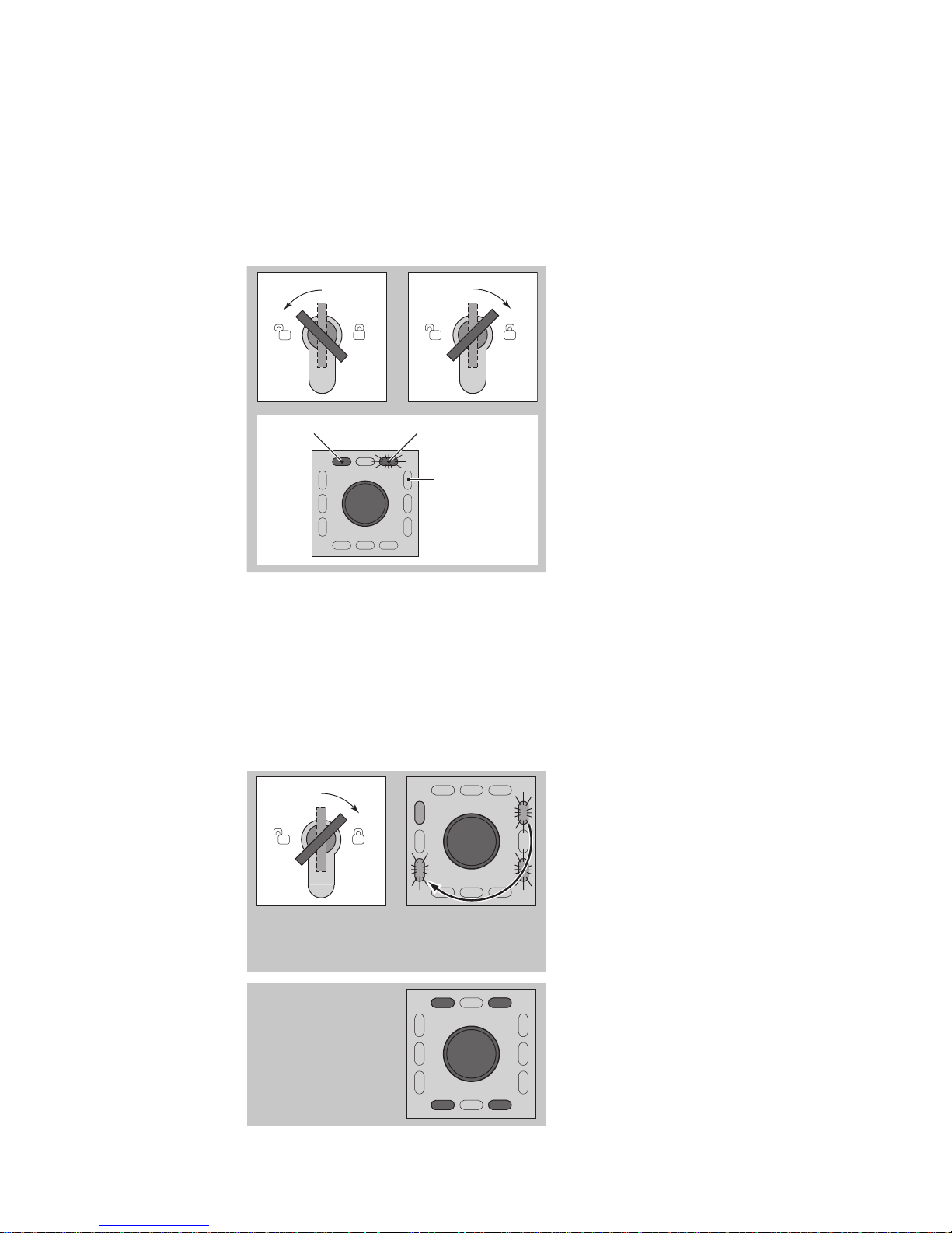
Symbols are used in the following. These mean:
Turn the key to the left/right.
LED lights up LED flashes
LED is dark
Indicator display.
The locked door can be released for the pre-set temporary release time.
• The door can be opened during the temporary release time.
• The door can remain open for the duration of the door monitoring interval.
• Once the door monitoring interval is exceeded, the pre-alarm is triggered.
• Time intervals can be set as required (see 'Change time intervals' section).
gn
gn
gn
gn
Turn the key to the right.
The door is released and can be
opened.
The left-hand upper LED lights
up.
The remaining green LEDs light
up and go out one after another in a clockwise direction.
rdrd
rd rd
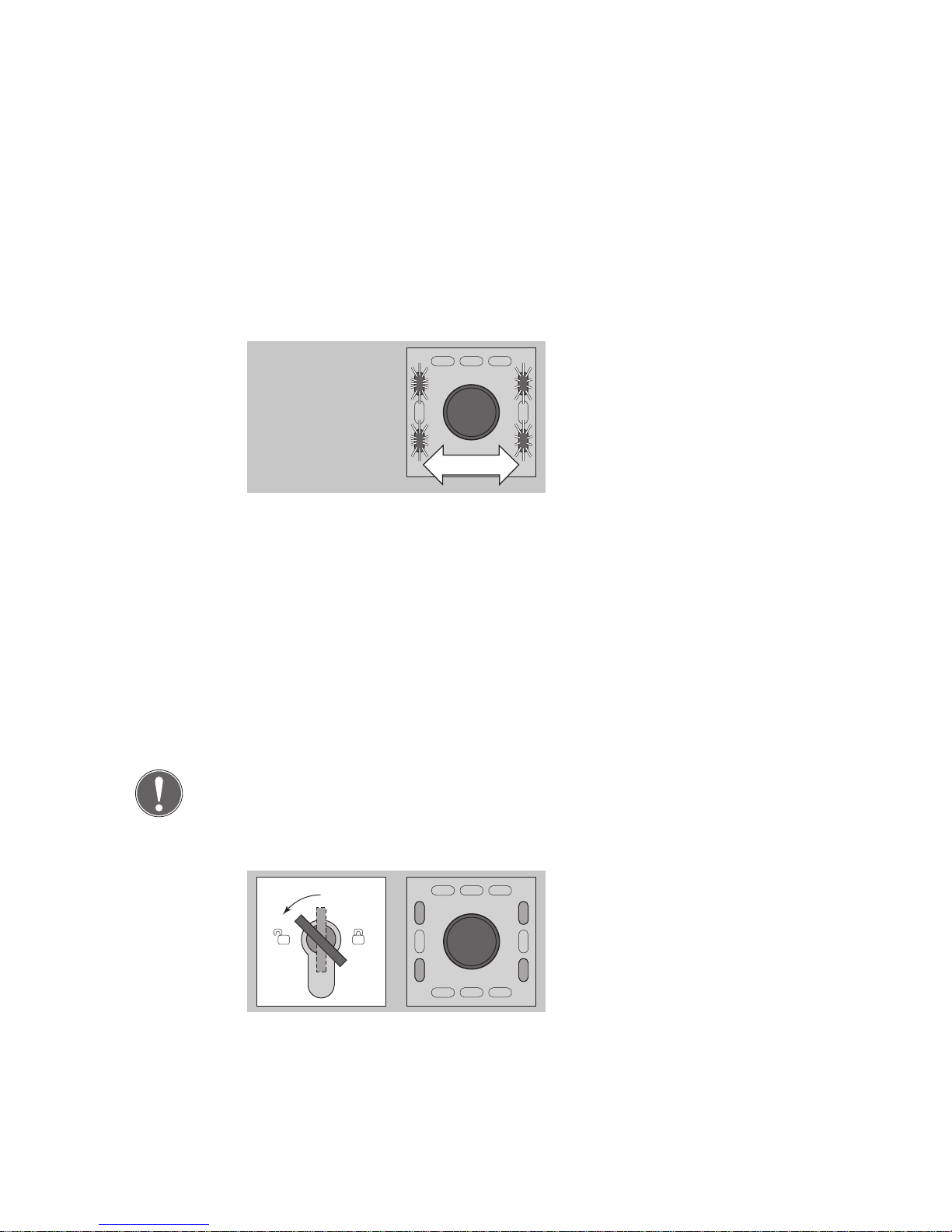
Close the door within the pre-
set door monitoring interval.
The four red LEDs light up.
The door is locked.
Explanation of
symbols
Temporaryrelease
Page 32
30
The pre-alarm is a reminder signal.
• This signal is time-limited.
• Time intervals can be set as required (see 'Change time intervals'
section).
gn
gn
gn
gn
The reminder signal is an audi-
ble intermittent signal.
The four green LEDs flash in
pairs.
After the pre-alarm interval has
elapsed, an alarm is triggered.
Pre-conditions for a pre-alarm:
After a temporary release when the opened door is not closed again
within the pre-set temporary release time.
After a permanent release mode and a subsequent pre-set temporary
release time interval have ended and the door is not closed.
If the door is closed within the pre-alarm interval, the pre-alarm ends and
the door is locked.
Note
An alarm occurring during a temporary release or pre-alarm interval (e.g.
emergency pushbutton is pressed) will be evaluated and signalled.
gn
gn
gn
gn
The door can be released.
Turn the key to the left.
The four green LEDs light up.
The door is released.
Pre-alarm
Permanent
release
Page 33
31
rdrd
rd rd
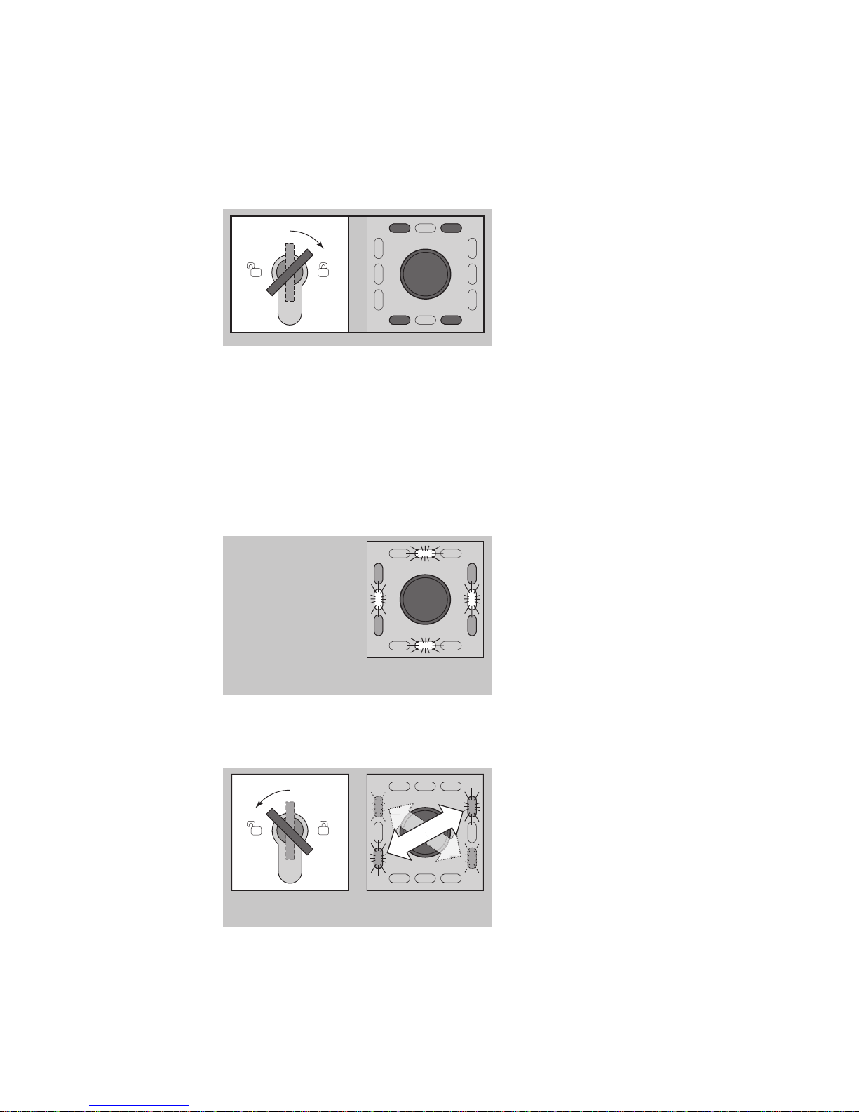
The door can be locked.
Close door if required.
Turn the key to the right.
The four red LEDs light up.
The door is locked.
Pre-conditions for locking:
The door is closed.
No alarm signal is present.
The danger alarm is triggered:
• By pressing the emergency button
• When activated by a fire alarm system
gn
ye
gn
ye
gn
ye
gn
ye
The door is released
immediately.
An audible alarm signal is
emitted.
The green LEDs light up.
The yellow LEDs and the EMER-
GENCY-OPEN-switch flash.
Acknowledging the alarm and main alarm indicator:
gn
gn
gn
gn
Turn the key to the left.
Alarm is acknowledged.
The 4 green LEDs flash in pairs
in a diagonal sequence.
The alarm signal is indicated by
an LED sequence pattern.
(see 'Alarm signals' )...
Locking
Danger alarm
Page 34
32
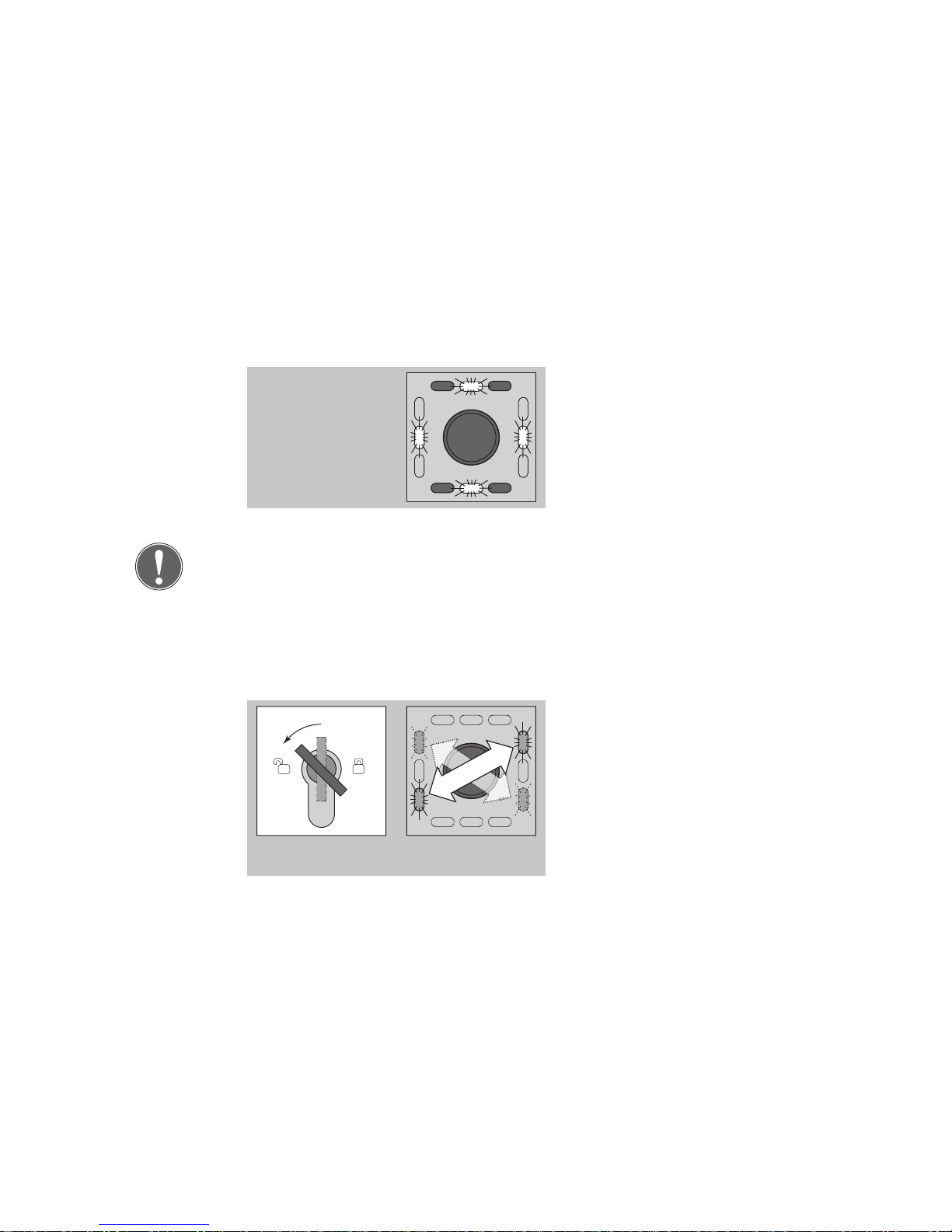
The tamper alarm is triggered:
• When the emergency button protective cover is opened
• By a door contact when a door is forced open
• When the cover on the key switch module is removed
• When the locking component is tampered with
ye
ye
ye
ye
rdrd
rd rd
An audible tamper alarm signal
is emitted.
The red LEDs light up.
The yellow LEDs flash.
Note
The door remains locked in the event of a 'tamper alarm'.
When a cover is closed or replaced again, the LED display and the audible
alarm continue to function.
Acknowledging the alarm and main alarm indicator:
gn
gn
gn
gn
Turn the key to the left.
Alarm is acknowledged.
The 4 green LEDs flash in pairs
in a diagonal sequence.
The alarm signal is indicated by
an LED sequence pattern.
(see 'Alarm signals' )...
Tamper alarm
Page 35
33
Several alarm statuses can be evaluated and signalled at the same time.
Note
The 4 green LEDs continue to flash in pairs in a diagonal sequence if the
cause of the alarm is still present after the alarm has been acknowledged.
The door can only be locked again when all alarm statuses have been reset and the causes of the alarm have been remedied.
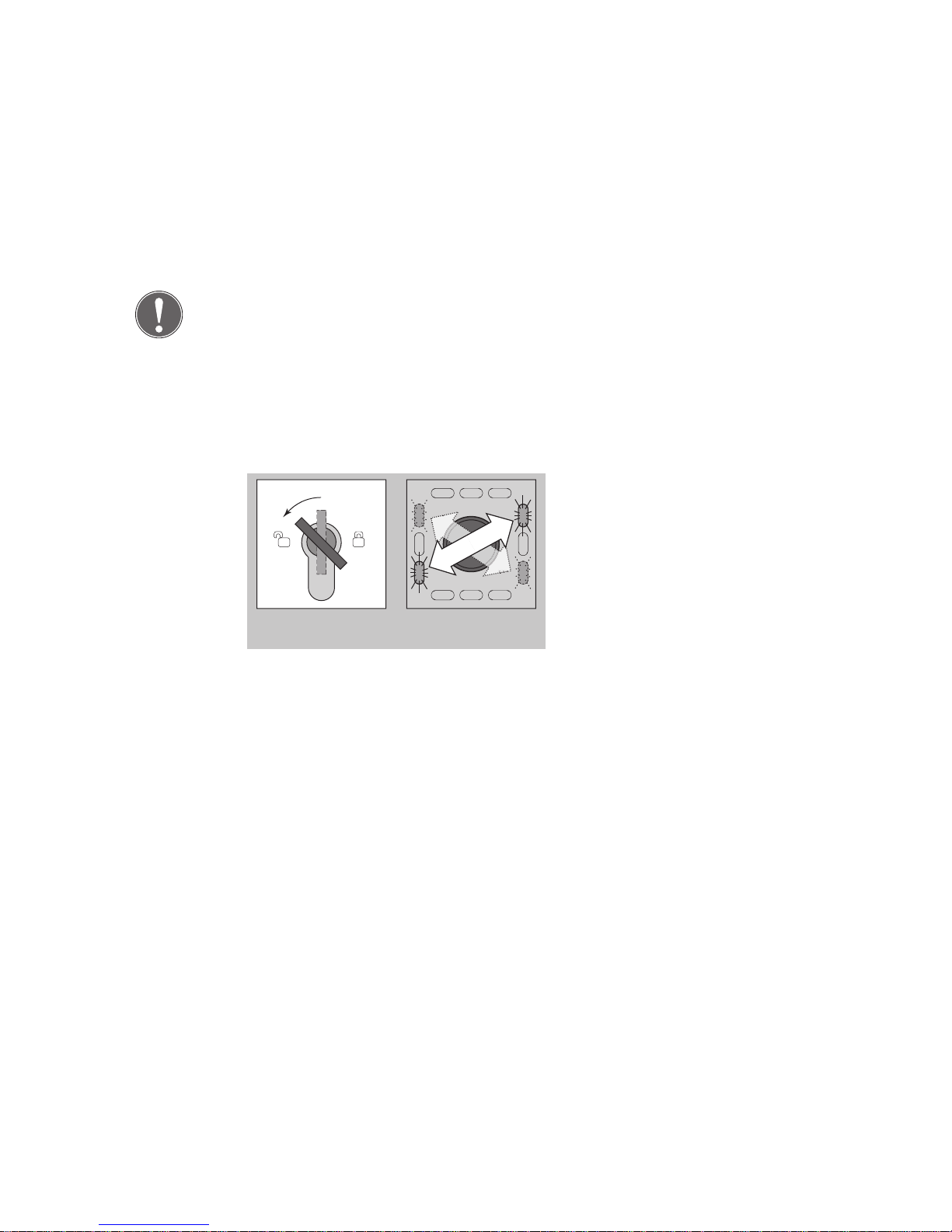
Acknowledging the alarm and main alarm indicator:
gn
gn
gn
gn
Turn the key to the left.
Alarm is acknowledged.
The 4 green LEDs flash in pairs
in a diagonal sequence.
The alarm signal is indicated by
an LED sequence pattern.
(see 'Alarm signals' )...
Multiple alarm
Page 36
34
Configuration
Note
A key switch is required to configure devices
1384
and
1385
(stand-alone).
You can configure a networked
1385
either with a key switch or by using
the
FT Manager
software within the building network (see separate
'
FT Manager
' operating instructions).
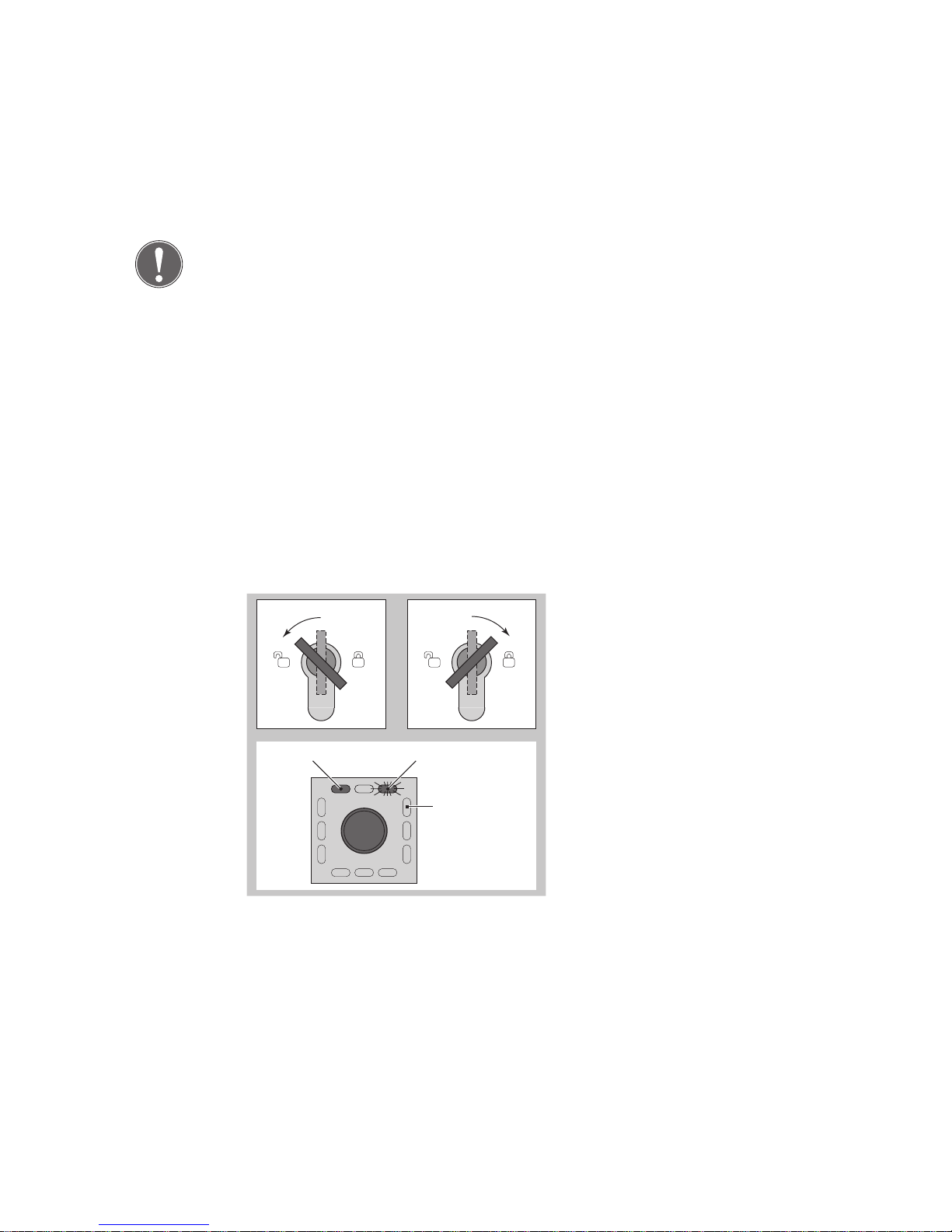
The escape door control terminal is configured using a key switch, via the
two switch contacts in the key switch module. The individual configuration modes and settings are displayed on the 12 different coloured LEDs
on the escape door module.
Data is permanently saved. It is not lost in the event of a power failure.
Symbols are used in the following. These mean:
Turn the key to the left/right.
LED lights up LED flashes
LED is dark
Indicator display.
General
Explanation
of symbols
Page 37
35
ye
ye
ye
ye
rdrd
rd rd
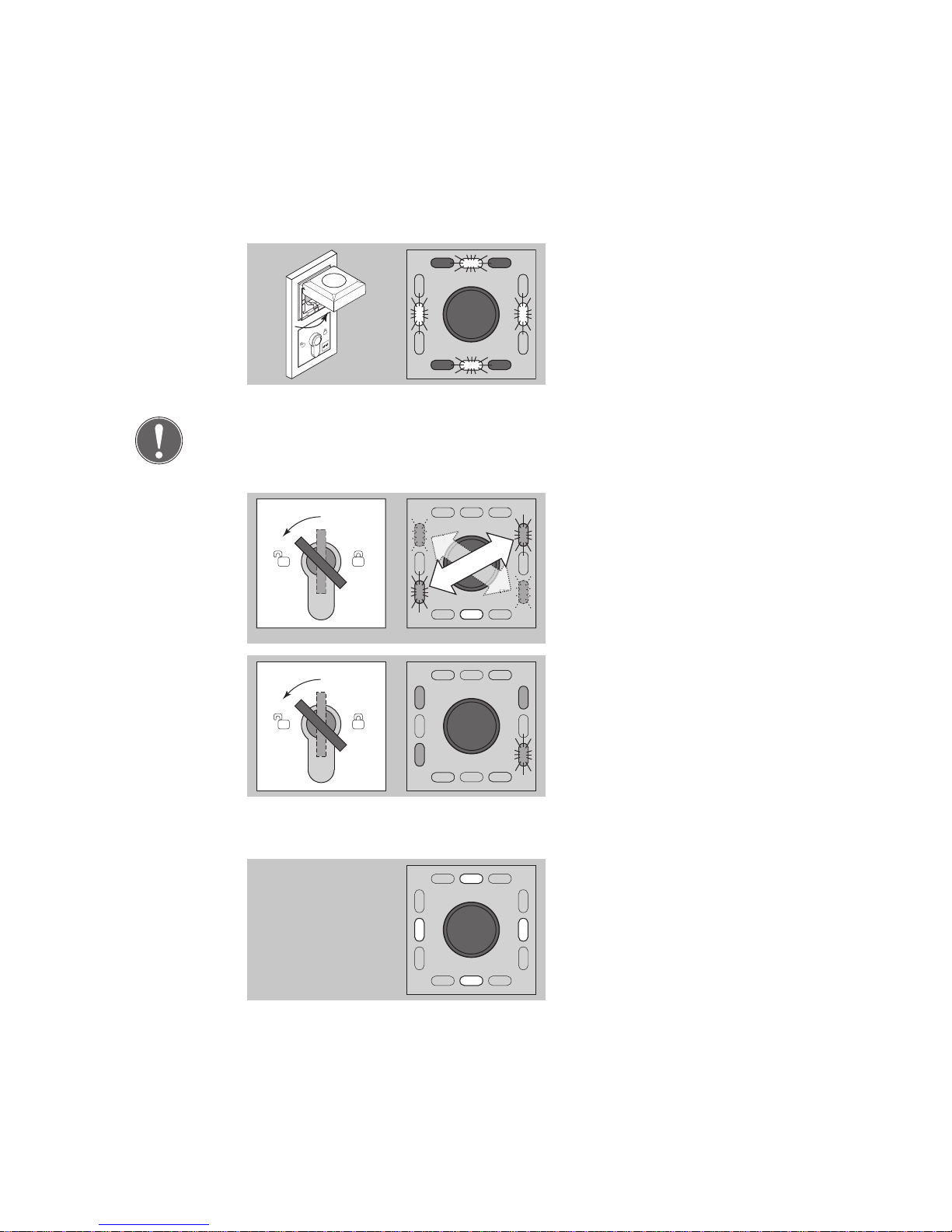
Open the protective cover on
the escape door module and
leave open.
The tamper alarm will be
triggered.
Note
The tamper alarm must remain active in order to access configuration
mode.
gn
gn
gn
gn
ye
Turn the key to the left
The audible signal will stop.
The 4 green LEDs flash in pairs
in a diagonal sequence.
The lower yellow LED will light
up.
5 s
gn
gn
gn
gn
Turn the key to the left and
hold for five seconds.
Three green LEDs light up.
The lower right-hand green LED
flashes.
5 s
ye
ye
ye
ye
The display will change after five
seconds.
The four yellow LEDs light up.
The configuration mode is now
switched on.
Starting configuration mode
Page 38
36
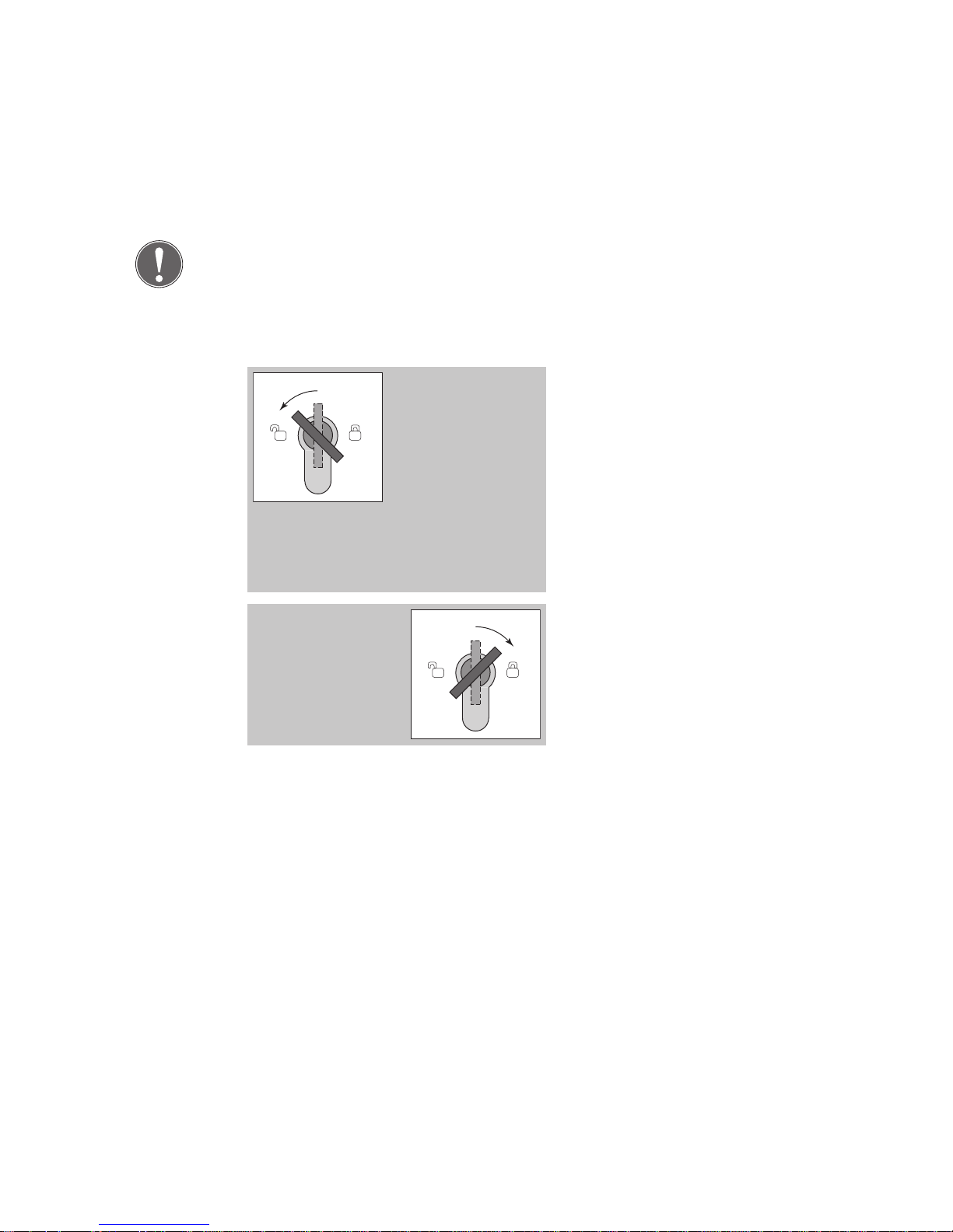
Note
There is only one menu level. This means all menu items can be selected
from here by briefly turning the key to the left to 'start'; there are no
submenus.
Turn the key to the left.
The following menu item is
displayed.
The LED display changes.
A short audible signal acknowl-
edges the key has been turned.
A long audible signal acknowl-
edges each time an input is
accepted.
Turn the key to the right.
The LED display changes.
A short audible signal acknowl-
edges the key has been turned.
Advancing
through menu
items
Defining
settings in the
menu
Page 39

37
1 - Profile
2 - Temporary release time
3 - Door monitoring time
4 - Pre-alarm time
5 - Alarm time
6 - Duration orientation signal
7 - Activation delay
8 - Alarm tones
9 - Request TSB address
10 - Master/Slave
11 - Display TSB address
12 - Re-set to factory settings
13 - End configuration mode
Menu structure
Page 40
38
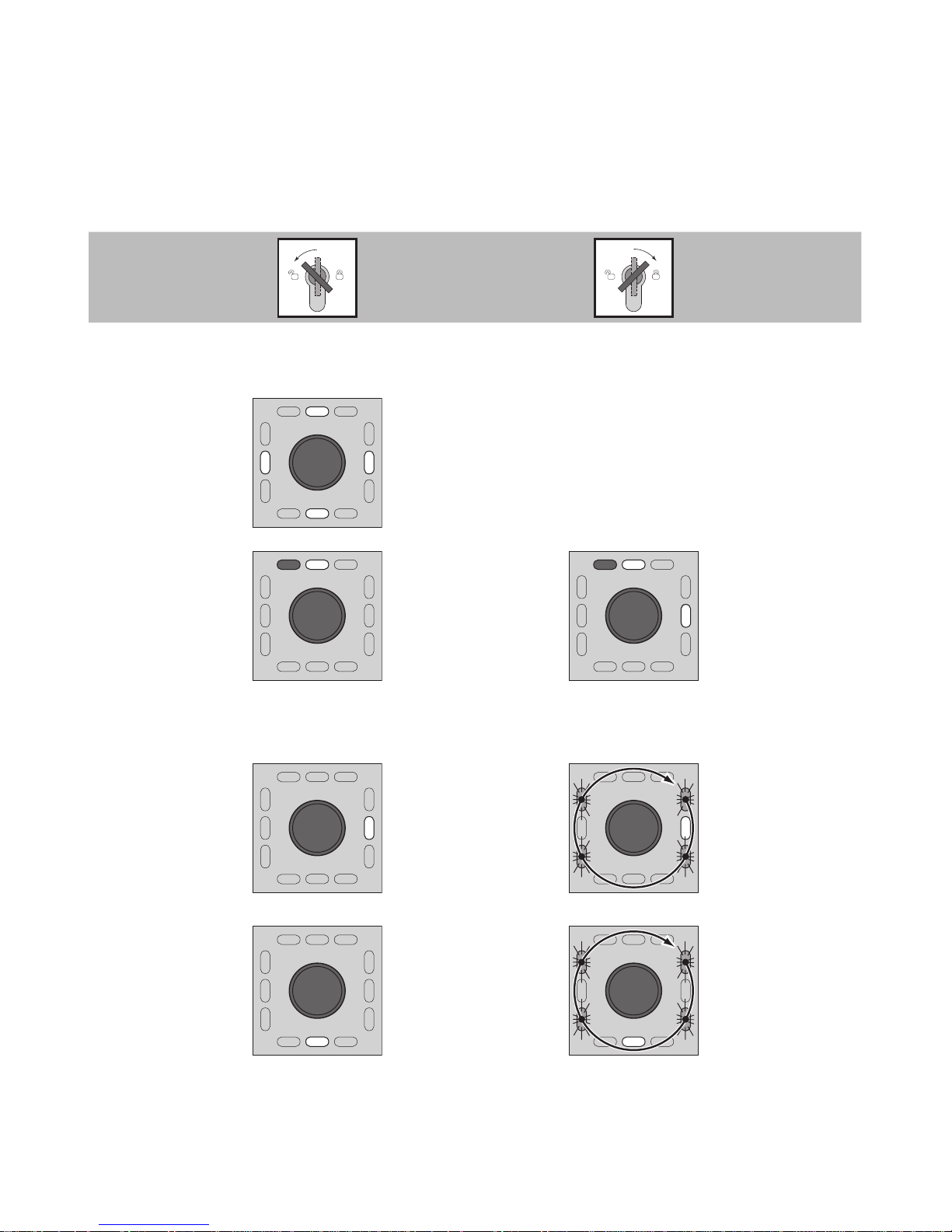
Menu items Description Configuration
Starting configuration mode
See 'Starting configuration mode' section
Configuration
mode switched
on.
ye
ye
ye
ye
The yellow
LEDs light up.
1 - Profile
rd ye
Different profiles (0 to 11)
can be selected
with specially
optimised
pre-settings
(see 'Profile
settings').
rd ye
6
5
4
1
2
3
9
7
8
Turn
Decimal display
0 = no LED
1 = LED1 etc.
10 = LED1 + 9
11 = LED2 + 9
2 - Temporary
release time
ye
Door locked
after temporary
release time interval if the door
remains closed.
gn
ye
gn
gn
gn
Hold
Time freely
adjustable.
1 complete turn
= 1 second
(max. 255 sec.)
3 - Door monitoring time
ye
The time interval starts after
the door has
been temporarily released and
opened.
gn
gn
gn
gn
ye
Hold
Time freely
adjustable.
1 complete turn
= 1 second
(max. 3,600
sec.)
Page 41
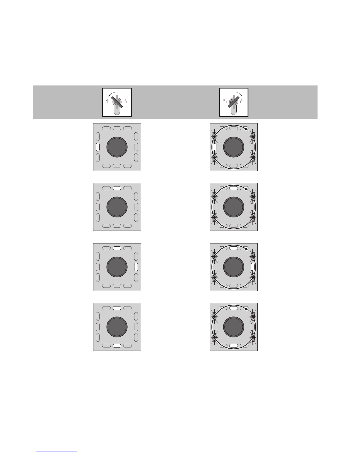
39
Menu items Description Configuration
4 - Pre-alarm
time
ye
Duration of prealarm until the
device triggers
the alarm.
gn
gn
gn
gn
ye
Hold
Time freely
adjustable.
1 complete turn
= 1 second
(max. 255 sec.)
5 - Alarm time
ye
After the
alarm interval
has elapsed,
the audible
alarm device is
switched off.
gn
gn
gn
gn
ye
Hold
Time freely
adjustable.
1 complete turn
= 1 second
(max. 255 sec.)
6 - Duration
orientation
signal
ge
ge
After the interval has elapsed,
the orientation
signal device is
switched off.
gn
ge
ge
gn
gn
gn
Hold
Time freely
adjustable.
1 complete turn
= 1 second
(max. 9999 sec.)
7 - Activation
delay
ge
ge
On turning the
key to the left:
The door will
only release if
the key is hold
on for the programmed time.
No delay if „0“ is
programmed.
gn
ge
ge
gn
gn
gn
Hold
Time freely
adjustable.
1 complete turn
= 1 second
(max. 255 sec.)
Page 42
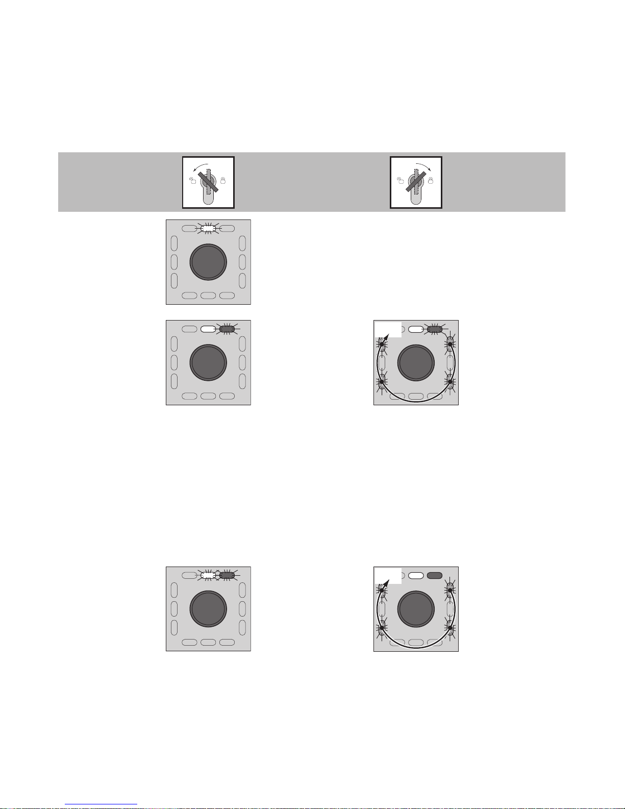
40
Menu items Description Configuration
8 - Alarm tones
ye
No function assigned:
Reserved for extension at a later
date
9 - Request TSB
address
ye rd
The door control bus address
is requested the
first time the
device is used
(
1385
).
ye rd
gn
gn
gn
gn
5 s
If the device is
online (
1385
):
Hold key in
position for 5
sec.
The system then automatically issues the next free address (
1385
).
The device then automatically
changes to the next but one menu
item: 'Display TSB address'.
The address
'1'
is automatically
displayed in the case of the 1384.
The address is requested.
A long audible signal is emitted
when the address is identified.
10 - Master/
Slave
ye rd
Display of current setting /
address conflicts
(
1385
) (see
'Master/Slave'
section).
Only the master
is displayed in
the case of the
1384
.
gn
gn
gn
gn
ye rd
5 s
Set device
as master
providing no
other master is
identified in the
system (
1385
).
Hold key in
position for 5
sec.
Page 43
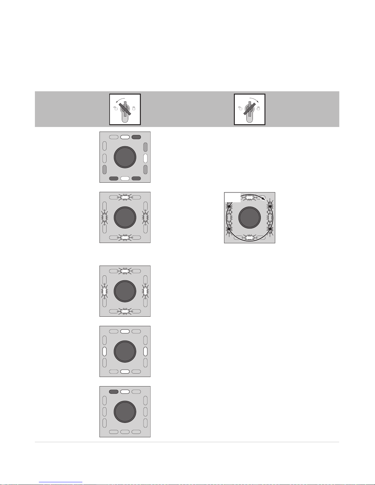
41
Menu items Description Configuration
11 - Display TSB
address
ye rd
32
16
8
1
2
4
64
Binary display of the door control bus address
Please read the 'Display TSB address, description'
section.
12 - Re-set to
factory settings
ye
ye
ye
ye
The device has
been re-set to
factory settings.
The yellow
LEDs flash
alternately in
pairs.
ye
ye
ye
ye
gn
gn
gn
gn
5 s
Hold key in
position for 5
sec.
A long au-
dible signal
follows.
13 - End configuration mode
ye
ye
ye
ye
The yellow
LEDs flash.
Configuration
mode switched
on
ye
ye
ye
ye
The yellow LEDs light up.
1 - Profile
rd ye
All menu items can be displayed and configured again
if you continue to turn the key switch to the left.
Page 44
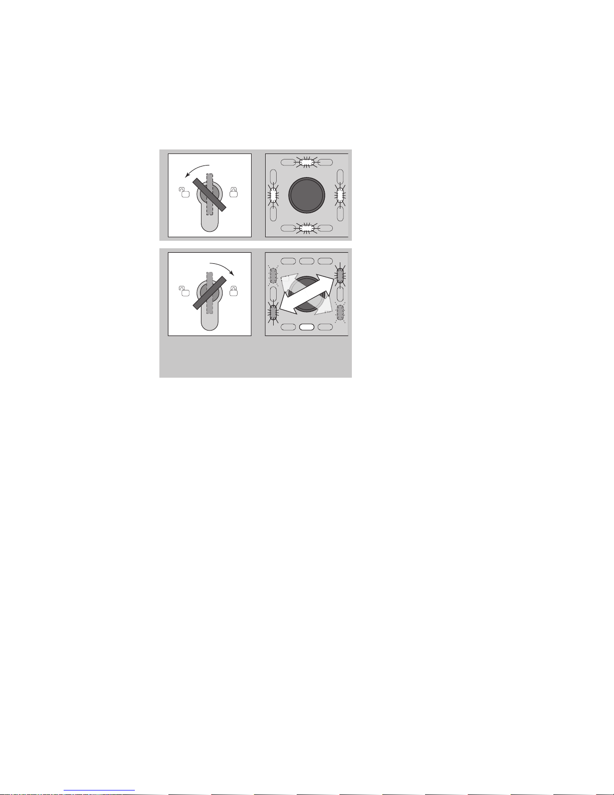
42
ye
ye
ye
ye
Turn the key to the left while in
configuration mode until the
four yellow LEDs flash (11 - End
configuration mode).
gn
gn
gn
gn
ye
Turn the key to the right.
A long audible signal is
emitted.
The 4 green LEDs flash in pairs
in a diagonal sequence.
The lower yellow LED lights up
Close the protective cover
again
Ending configuration mode
Page 45

43
If no input is made within one minute while in configuration mode, the
device automatically switches to operational mode.
Several short audible signals are emitted.
Automatic
change from
configuration
mode
Page 46
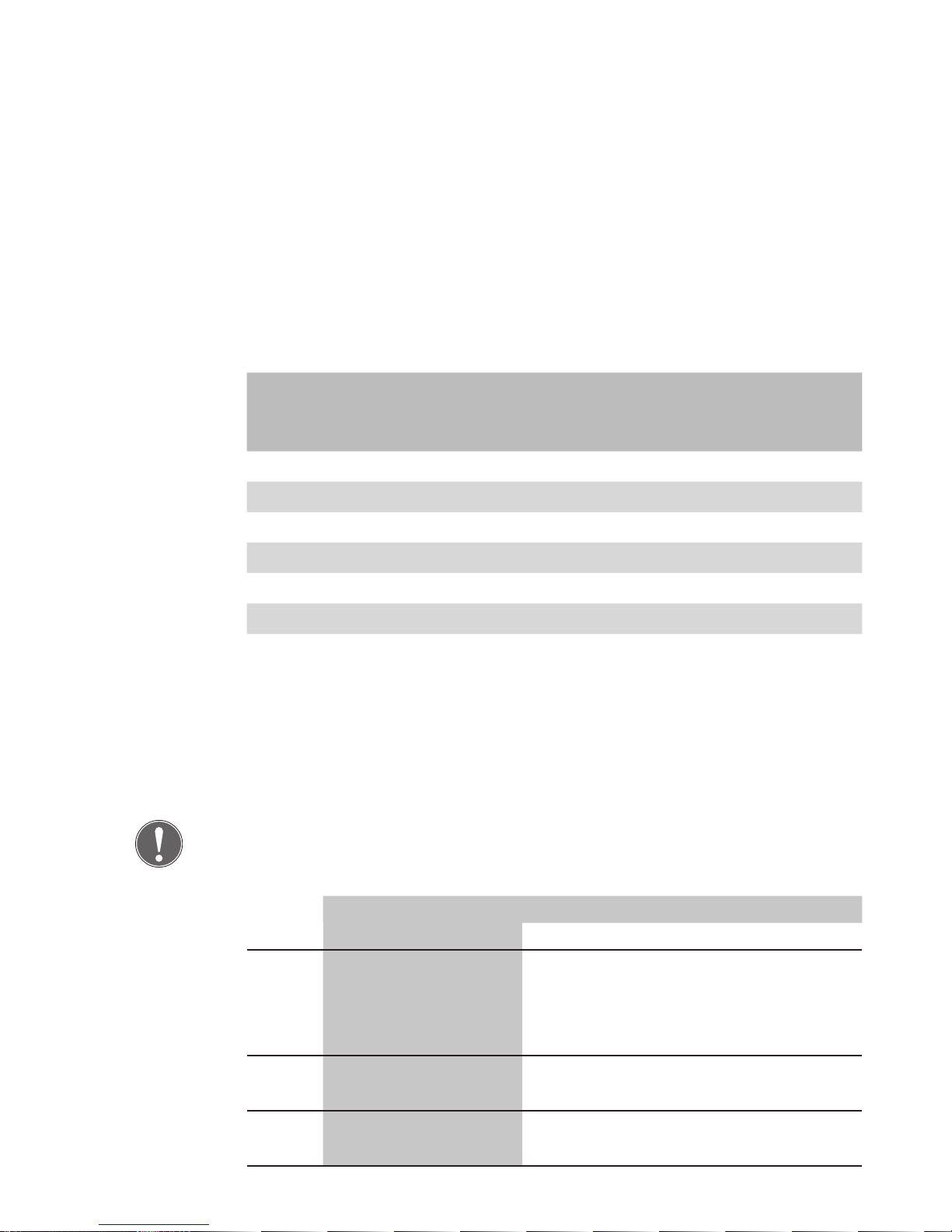
44
The available profiles consist of optimised pre-settings, which you can
access.
Die Parameter were factory set.
The following table shows the values of the factory setting and the possible setting range. All values in seconds.
Parameter Factory
setting
Einstellbar
from up to
Temporary release 5 1 255
Opening 50 1 3600
Monitoring 60 1 3600
Pre-alarm 10 1 3600
Alarm signal 180 0 255
Orientation signal 600 0 9999
Activation delay 0 0 255
Configuration using
FT Manager
(1385 - networked)
If changes are made, you must always select Profile
'0'
(called functions
templates in FT Manager) as it is the only place where changes can be
saved.
Note
Profile '0' is set by default when the device is delivered.
Profile Description
Input
Output
0 External temporary
release
Combined with a motorized or solenoid lock, or with an electric strike,
to release the door in the direction of
escape
1 External temporary
release
To connect to an external locked mode
monitoring unit
2 External temporary
release
To actuate a door operator
Profile settings
Page 47

45
Profile Description
Input
Output
3 External temporary
release
To connect to a flashing light or an
alarm siren (without time restriction)
(inverse)
4 Fire detector system
(inverse)
To connect to a flashing light or an
alarm siren (without time restriction)
(inverse)
5 Burglar alarm system To connect to an external locked mode
monitoring unit
6 Operated via a
contact in the access
control system only
Combined with a motorized or solenoid lock, or with an electric strike,
to release the door in the direction of
escape
7 Operated via a
contact in the access
control system only
To connect to an external locked mode
monitoring unit
8 Operated via a
contact in the access
control system only
To actuate a door drive
9 Operated via a
contact in the access
control system only
To connect to a flashing light or an
alarm siren (without time restriction)
(inverse)
10 External temporary
release
Special function: SW time delay; connection to locking element
11 Operated via a
contact in the access
control system only
Special function: SW time delay; connection to locking element
Page 48
46
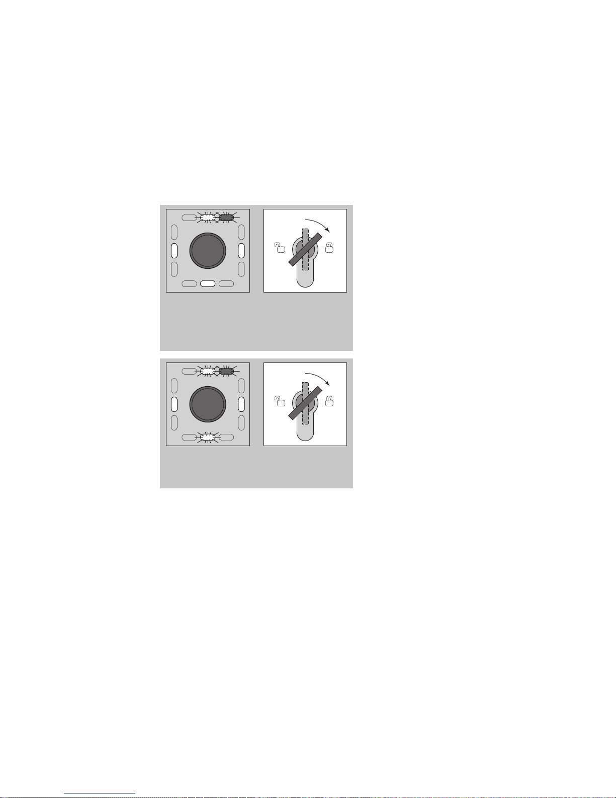
The master/slave configuration menu (
1385
only) enables you to use
the LED display to identify which slaves are online or offline, or have an
address conflict.
6
5
4
1
2
3
7
8
ye rd
The LEDs 1 to 8 indicate the
address (LED1 = 1, LED2 = 2,...)
where a device on the bus has
detected the master in the
1385
.
If one of the devices has a
problem (gone offline, address
conflict), the corresponding LED
will flash.
6
5
4
1
2
3
7
8
ye rd
Turn the key to the right.
This will indicate which of
the flashing bus devices has
an address conflict. Once you
let go of the key, the display
is updated, so that you can
see whether the bus device in
question is now online again.
Master/Slave
Page 49
47
6
5
4
1
2
3
7
8
ye rd
10 s
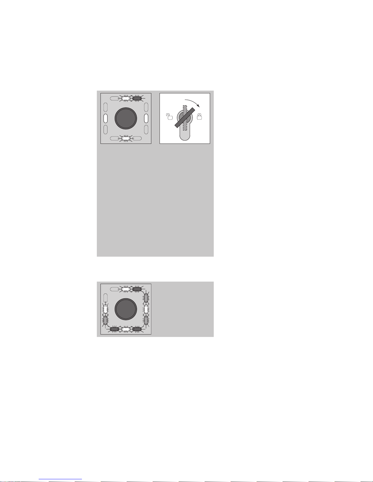
You can eliminate address
conflicts.
Turn the key to the left and
hold for ten seconds.
After five seconds, a bleep will
be heard every second.
A long acknowledgement
signal is emitted after ten
seconds.
An available address has been
assigned.
Note:
If the key is turned to the right
for more than ten seconds, the
address conflict is eliminated and
the bus is scanned again.
6
5
4
1
2
3
7
8
ye rd
If all eight LEDs (1-8) are flashing,
there is a short circuit in the bus.
Identify the cause of the short
circuit and rectify.
Page 50
48
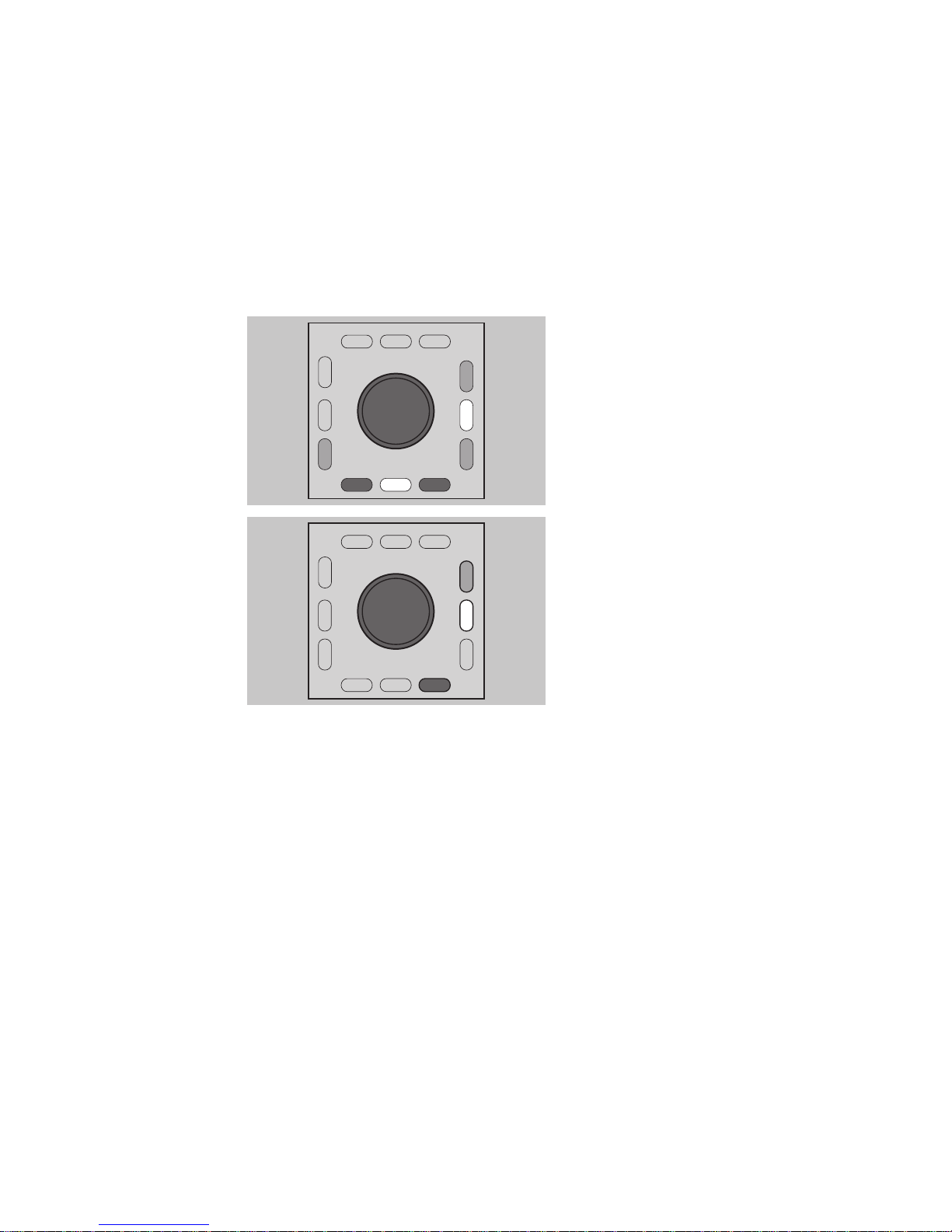
The TSB address is displayed as a LED sequence in binary form:
Display
32
16
8
1
2
4
64
Individual LEDs are assigned corresponding binary numbers. An
accumulative value between 0
and 255 is indicated depending
on which LEDs light up.
If no LED lights up, then the binary
value is 0.
32
16
4
64
8
1
2
Example on the left:
The LEDs light up with the values
1 + 2 +8.
This results in an accumulative
value of 11.
Display TSB
address
Page 51

49
The following procedure serves as an example of how you can use the key
switch to set and save the pre-alarm time at twenty seconds.
Starting configuration mode
Open the protective cover on the escape door module and leave open.
Turn the key to the left.
Turn the key to the left and hold for five seconds.
Changing to the 'Pre-alarm time' menu.
Turn to the left four times using the key.
You are now in the 'Pre-alarm time' configuration menu. This is dis-
played by the left-hand yellow LED lighting up.
Configuring pre-alarm time
Now turn the key to the right and hold it there for the required alarm
time (twenty seconds).
The green LEDs flash alternately in a clockwise direction with each
cycle representing one second.
The change you have made will be saved as soon as you let go of the
key.
Leaving the configuration menu
Turn the key to the left until the four yellow LEDs flash.
Turn the key to the right.
The 4 green LEDs flash alternately in pairs in a diagonal sequence and
the lower yellow LED lights up.
Close the protective cover again.
The device has been configured and is ready to operate.
Example
configuration
Page 52

50
Delayed release after EMERGENCY-OPEN is activated
Concept
If a terminal with an EMERGENCY open element is used instead of an
operating unit, it can be used to request the door be unlocked from the
main control centre and alarm signals ensure security staff are alerted to
control doors. This ensures hazardous situations are detected more
quickly and operational reliability is enhanced.
The EMERGENCY-OPEN delay postpones an EMERGENCY-OPEN request for
a specified interval, so that security staff can check and decide whether it
is legitimate or not.
The EMERGENCY pushbutton on doors thus serves as an alarm device
here.
Note
The EMERGENCY-OPEN delay may only be used on escape routes where
there is an EMERGENCY-OPEN control panel (indirect unlocking) and
apermanently manned control centre.
Operation sequence
EMERGENCY-OPEN pushbutton is pressed.
An audible alarm is triggered; the door remains locked, however.
The display flashes red.
An audible alarm is emitted on the bus control panel in the perma-
nently manned control centre.
The operator now decides whether the EMERGENCY-OPEN request is
legitimate.
If so, the door can then be opened using the centrally controlled EMERGENCY-OPEN pushbutton (indirect unlocking).
If the special 'Delayed release after EMERGENCY-OPEN activation' function has been selected in
FT Manager
or pre-set in Profile XX, you can
repeat triggering of the delay time one or more times (depending on the
configuration).
Special function
1385
- networked
Page 53
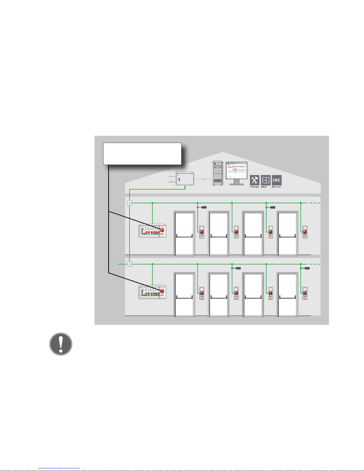
51
If you don't do this, the door automatically opens after the pre-set delay
interval.
Schematic diagram
Tableau 925 BSM
Bus-Repea ter 901 -35
Tableau 925 BSM
Bus-Repea ter 901 -35
2
2
BMA
EMA
RS 232
Note
Security-relevant doors are unlocked on the bus control panel in the
permanently manned control centre and not at the door itself.
Safety-relevant
Unlocking
Page 54
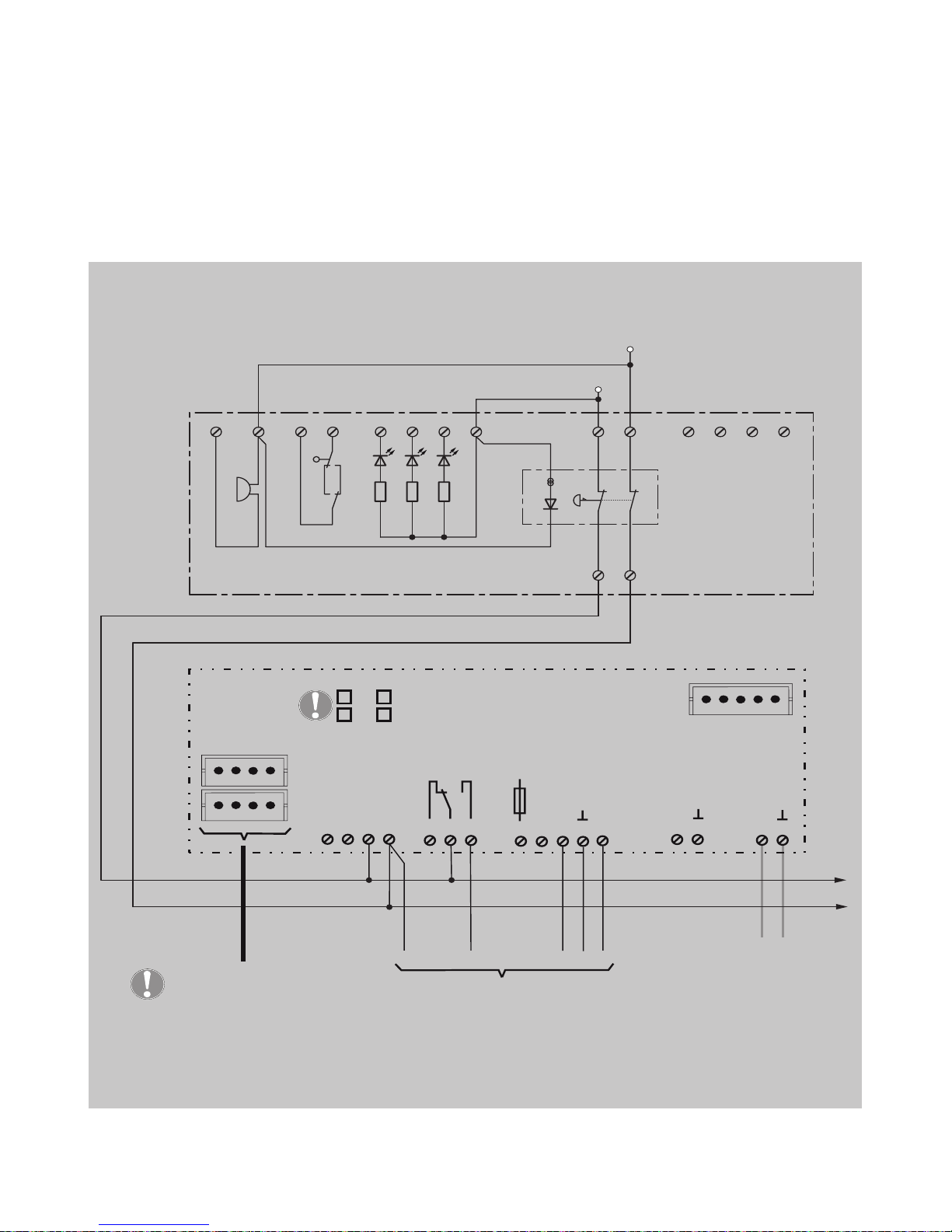
52
Circuit diagram
S2
JP
1
2
3
S
+
-
+
-
5 8 7 6 9121110 31 16151413
4
2
F1
Littelfuse
154001
1AF
2
1
3
4
5
6
7
8
9
11
12
10
13
14
15
16
AB ED F
Data
LB1
LB2
Power supply via a external power unit
12 - 24 VDC +15% / -10%
according to the connected
locking element
Connection of the
respective locking
element
Power supply via
SYSCON 4
SYSCON-5
Emergency button
1380
SYSCON-4
max. 24V / 1A
See instruction D00470..
Remove jumpers LB1/LB2
To additional 1385
TS-Bus to
Bus-panel
(permanently occupied
central point)
Kl. 4
Kl. 3, 6
Page 55
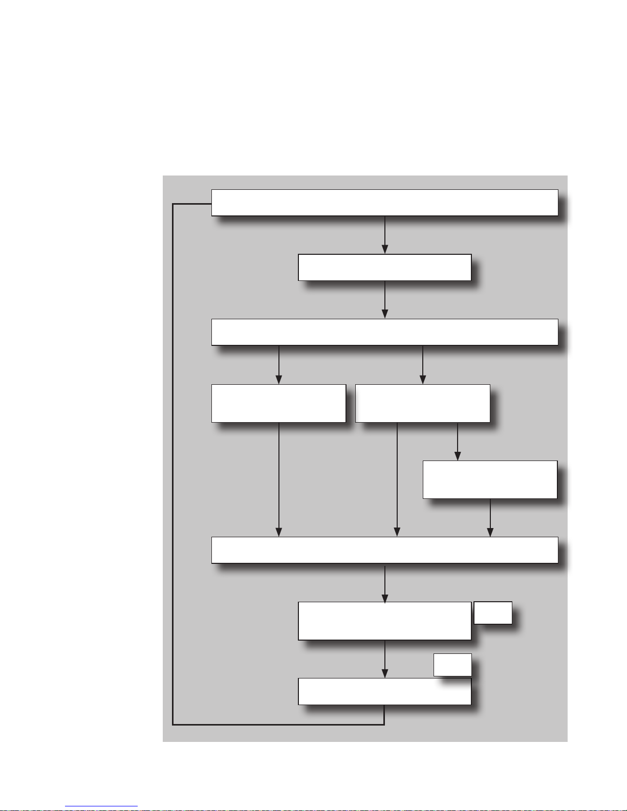
53
Sequence of operation
Door secured (exit blocked)
EMERGENCY PUSHBUTTON
FT Manager
Delay period 1
FT Manager
Delay period 2
Central
EMERGENCY-OPEN
Conditions valid for
re-setting?
Re-setting
Signal to permanently manned control centre
Enable door
No
Yes
Page 56

54
Check list - Testing before initial
operation
Individual components should be checked in a suitable way.
Description Yes No
Does installed locking element comply with guidelines
for electronic locking systems in escape route doors?
Do controls comply with guidelines for electronic locking systems in escape route doors?
Does operating device comply with guidelines for electronic locking systems in escape route doors?
Do you have fitting and installation instructions at
hand?
Do you have the form for escape door locking system
testing before initial operation at hand?
In the case of external power supply to the locking
system or parts thereof:
Does the power supply unit comply with EN 60 950
(does it feature the CE mark)?
The general installation set-up should be checked.
Description Yes No
The locking element does not limit the door headroom
to under 200 cm?
Does the escape door module comply with local building legislation specifications and guidelines for electrical locking devices for doors on escape routes?
Is the 'EMERGENCY BUTTON' sign present and correctly
affixed?
If the locking unit is installed on fire and/or smoke
doors:
Do the locking element's position and installation type
comply with the door manufacturer's verification of
suitability specifications?
Components
Installation
Page 57
55
Locking
Close door
Activate locking element.
Description Yes No
Do the four red LEDs light up?
Is the door securely locked? (test manually)
Temporary release
Activate temporary release element.
Description Yes No
The left-hand upper green LED lights up.
The three remaining green LEDs switch off one after
another in a clockwise direction.
Is the door released? (test manually)
Pre-alarm
Open the door and keep open.
Description Yes No
Does an audible alarm sound as an audible intermittent
signal after the door monitoring interval ends?
Do the four green LEDs flash in pairs?
Close door
Description Yes No
Is the door securely locked? (test manually)
Do the four red LEDs light up on the escape door
module?
Activate temporary release element.
Open the door and keep open longer than the pre-alarm delay interval.
Description Yes No
Is the danger alarm (audible alarm signal) triggered?
Function
Page 58
56
Description Yes No
Do the four green LEDs light up?
Do the four yellow LEDs flash?
Close door
Re-set alarm.
Description Yes No
Do the four green LEDs light up?
Is the door released? (test manually)
Activate locking system.
Permanent release
Activate permanent release.
Description Yes No
Is the door released? (test manually)
Can the door be opened without using considerable
effort?
Do the four green LEDs light up?
Danger alarm
Activate locking system.
Activate emergency pushbutton.
Description Yes No
Is the door released without a delay?
Can the door be opened without using considerable
effort?
Do all the green LEDs light up?
Do the yellow LEDs flash?
Does the audible alarm signal activate?
Does the emergency key button flash?
Open the protective cover on the escape door module and leave open.
Close the protective cover.
Re-set alarm.
Page 59
57
Description Yes No
Do the four green LEDs light up?
Does the audible alarm signal switch off?
Does the emergency key light up?
Tamper alarm on the escape door module
Activate locking system.
Open the protective cover on the escape door module.
Description Yes No
Do the red LEDs light up?
Do the yellow LEDs flash?
Is the tamper alarm (audible alarm signal) triggered?
Does the door remain locked? (test manually)
Close the protective cover on the escape door module.
Description Yes No
Do the red LEDs light up?
Do the yellow LEDs flash?
Does the audible alarm signal remain active?
Does the door remain locked? (test manually)
Re-set alarm.
Tamper alarm on the key switch module
Activate locking system.
Remove the cover from the key switch module.
Description Yes No
Do the red LEDs light up?
Do the yellow LEDs flash?
Does the audible alarm signal remain active?
Does the door remain locked? (test manually)
Page 60

58
Replace the cover onto the key switch module.
Description Yes No
Do the red LEDs light up?
Do the yellow LEDs flash?
Does the audible alarm signal remain active?
Does the door remain locked? (test manually)
Re-set alarm.
If a danger alarm system such as a fire alarm system is activated.
Activate locking system.
Description Yes No
Do the red LEDs light up on the escape door module?
Is the door securely locked? (test manually)
Open the fail-unlocked loop in the danger alarm system.
Description Yes No
Is the door released without a delay?
Can the door be opened without using considerable
effort?
Do all the green LEDs light up?
Do the yellow LEDs flash?
Does the audible alarm signal activate?
Re-set alarm on the key switch.
Close the fail-unlocked loop in the danger alarm system.
Description Yes No
Do the four red LEDs light up?
Does the audible alarm signal switch off?
Page 61

59
Maintenance
A technical specialist must:
carry out an annual inspection of escape route doors with electric lock-
ing systems.
issue an inspection certificate, which the building operator must sub-
mit to the building inspection authorities if required.
Note
These instructions are standard specifications. As the use of escape route
locking systems is regulated on a national or local basis, respective local
building legislation and inspection regulations for technical systems
should be observed.
Escape door control terminals do not require any maintenance. If faults
which are not caused by faulty installation or fitting occur during operation or during one of the compulsory tests, the device in question should
be taken out of service immediately and sent to the manufacturer to be
checked.
The fact devices do not require maintenance does not release building
operators from the obligation to subject escape door locking systems to
inspection on a regular basis.
Annual
inspection
Maintenance
Page 62
60
Alarm signals
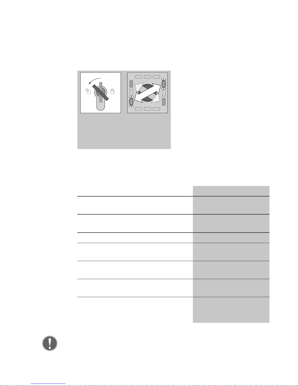
gn
gn
gn
gn
Alarm signal is present.
Turn the key to the left.
Alarm is acknowledged.
The 4 green LEDs flash in pairs
in a diagonal sequence.
The alarm signal is indicated by
an LED sequence pattern (see
the following table).
Eliminate the cause of the
alarm.
The green LEDs flash in pairs in a diagonal sequence.
You can also identify the following indicator displays which represent
alarm criteria.
Additional indicator displays Alarm criteria
EMERGENCY-OPEN
switch
LEDs
Dark - Centrally operated
release
Flashes - EMERGENCY-OPEN
Lights up - Central EMERGENCY-
OPEN activated
Lights up UPPER yellow LED
lights up
External emergency release (fire alarm system)
Lights up LOWER yellow LED
lights up
Tampering with terminal
Lights up LEFT-HAND and
RIGHT-HAND LEDs
flash
Device or E/A module
offline
Note
The LED indicator display will remain active and the door cannot be
locked while the alarm is present.
Identification of
alarm criteria.
Page 63
61
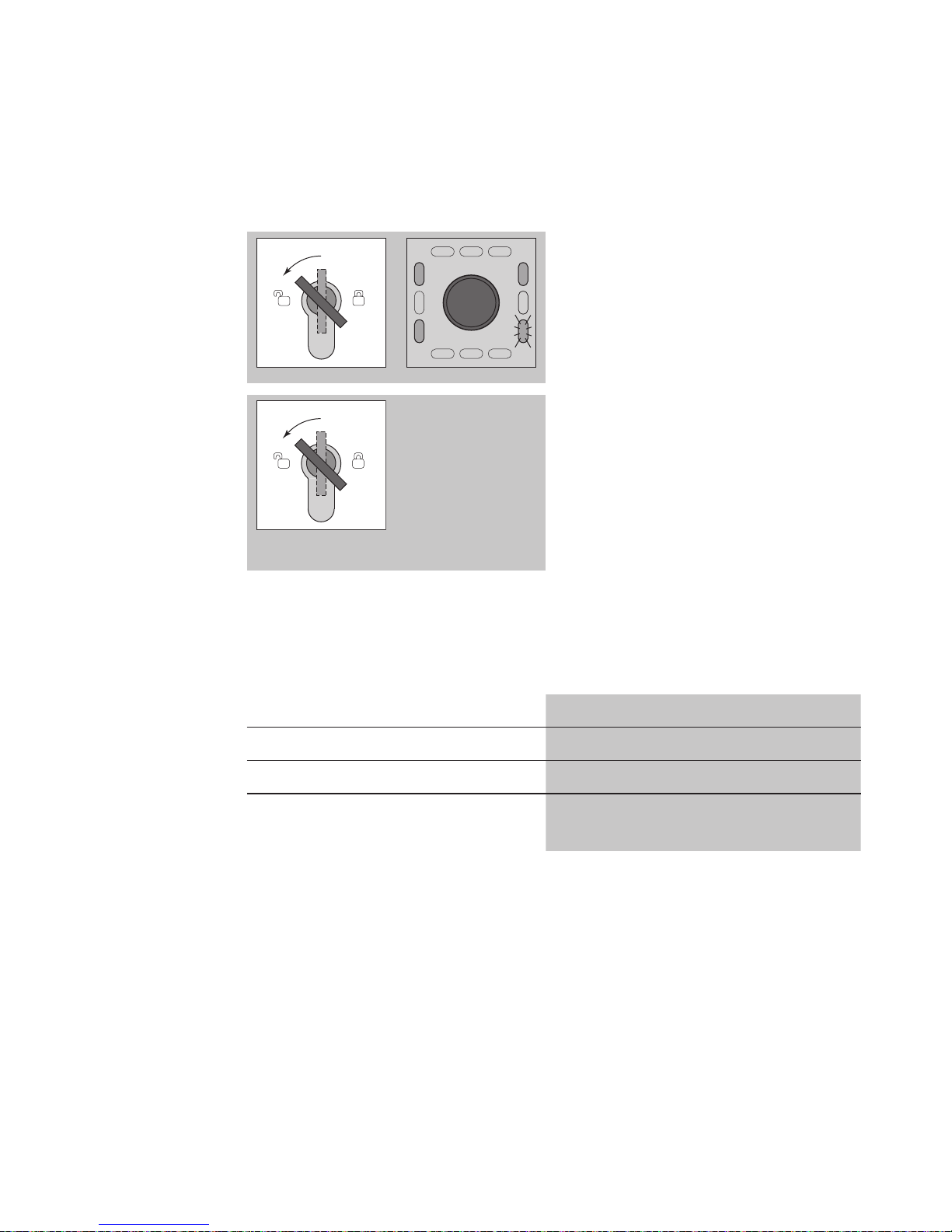
gn
gn
gn
gn
Alarm signal is present.
Turn the key to the left.
Alarm is acknowledged.
Three green LEDs light up.
The lower right-hand green LED
flashes.
Turn the key to the left and
hold.
The cause of the alarm is indi-
cated by an LED sequence pattern (see the following table).
Eliminate the cause of the
alarm.
Three green LEDs light up and the lower right-hand green LED flashes.
You can also identify the following indicator displays which represent the
cause of the alarm.
Additional indicator displays Cause of alarm
Right-hand yellow LED lights up Centrally operated release
Left-hand yellow LED lights up EMERGENCY-OPEN
Both yellow LEDs above and below light up.
Central EMERGENCY-OPEN
activated
Identification of
the cause of the
alarm
Page 64
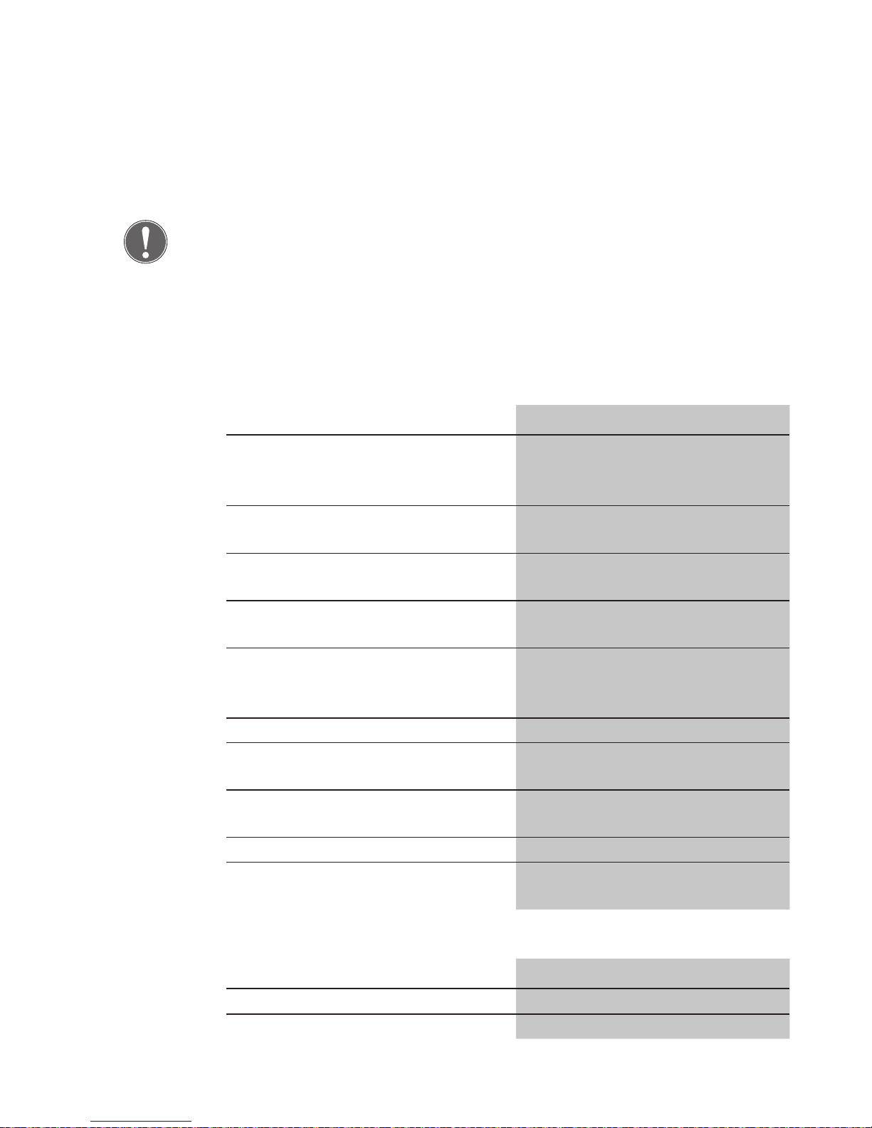
62
Technical Specifications
Note
The power supply unit must comply with limits established in IEC/EN
60950 with regards to limited capacity power sources. The maximum
output rating is limited to 100 W.
In the case of power supplies >100 W, a pre-fuse rated at 4 A for 24 V DC
or rated at 8 A for 12 V DC should be provided by the customer.
Electrical data
Description Value
Input voltage range
(ext. power supply)
12 V DC -15% to 24 V DC +15%
Regulated direct current
(low safety voltage)
Max. own input current at
12 V DC
about 150 mA
Max. own input current at
24 V DC
about 100 mA
Input voltage range
( terminals 12/13 )
Low– Active (0V)
Input voltage range
(terminal 10)
+12 V -15 % to +24 V +15 %
Regulated direct current
(low safety voltage)
Safety fuse F1 1 AF, Littelfuse 154001
Contact rating (relay) with ohmic
load
30 V / 1 A
Contact rating (relay) with inductive
load
30 V / 1 A
Safety measure Low safety voltage
Protection system according to
DIN/EN 60529
IP30
Mechanical data
Description Value
Operating temperature range -20°C to +40°C
Storage temperature range -20°C to +60°C
Escape door
module
Page 65
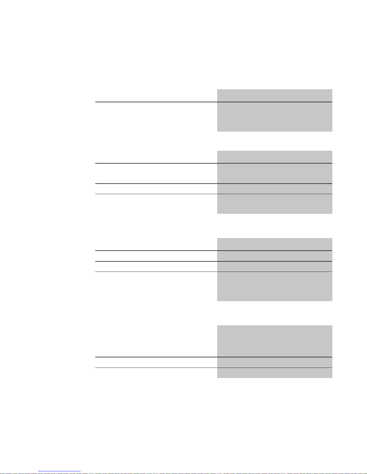
63
Description Value
Installation dimensions For standard flush-mounted
boxes:
62.5 mm deep
Electrical data
Description Value
Contact rating Micro-switch
Max. 12 V/0.1 A (ohmic load)
Safety measure Low safety voltage
Protection system according to
DIN/EN 60529
IP30
Mechanical data
Description Value
Operating temperature range -20°C to +40°C
Storage temperature range -20°C to +60°C
Installation dimensions For standard flush-mounted
boxes:
62.5 mm deep
Dimensions
Description Size
(Centre of mounting screw - cyl-
inder leading edge)
DIN profile half cylinder 30.5 mm
Lock catch 180°
Key switch
module
Profile half
cylinder
Page 66

64
Page 67

65
Page 68

effeff, 1936 als Werkstatt für
Feinmechanik und Elektrotechnik
gegründet, ist die weltweit führende Marke für elektromechanische
Ver- und Entriegelung.
Elektro-Türöffner, Elektro-Riegel, Sicherheitsschlösser, Zutrittskontrollsysteme und Rettungswegtechnik
zählen zu den Produkten der Marke
effeff, die heute in über 75 Ländern
der Welt für Sicherheit und Komfort sorgen.
IKON, hervorgegangen aus der
1926 gegründeten ZEISS IKON
AG, ist in Deutschland die erfolgreichste Marke von ASSA ABLOY für
Schließ- und Sicherheitstechnik.
Produkte und Lösungen der Marke
IKON nehmen eine Spitzenposition
ein und sind state-of-the-art. Das
Markenprogramm umfasst qualitativ hochwertige mechanische und
mechatronische Schließzylinder,
Zusatzschlösser und -sicherungen,
Türbeschläge und Türschließer. Sie
sorgen für aktiven Einbruchschutz
und schützen Menschen und
Werte.
Die ASSA ABLOY Sicherheitstech-
nik GmbH ist weltweit der kompetente Partner für mechanische und
elektromechanische Sicherheitslösungen für Schutz, Sicherheit und
Komfort im Gebäude.
Das Unternehmen entwickelt,
produziert und vertreibt unter den
traditionsreichen Marken IKON
und effeff qualitativ hochwertige
Produkte und vielseitige Systeme
für den privaten, gewerblichen und
öffentlichen Bereich.
ASSA ABLOY ist der weltweit führende Hersteller und Lieferant von
Schließlösungen und Sicherheitssystemen, die den hohen Ansprüchen der Kunden an Sicherheit,
Schutz und Benutzerfreundlichkeit
gerecht werden. Mit über 30.000
Mitarbeitern erwirtschaftet die
Gruppe einen Jahresumsatz von
über 3 Milliarden Euro.
ASSA ABLOY
Sicherheitstechnik GmbH
Bildstockstraße 20
72458 Albstadt
Tel. +49 (0) 74 31 1 2 3-0
Fax +49 (0) 74 31 1 23-2 40
ASSA ABLOY is the global
leader in door opening
solutions, dedicated to
satisfying end- needs
for security, safety and
convenience.
 Loading...