

QC5000MQC5000M
QC5000MQC5000M
Version 1.0
Published April 2015
Copyright©2015 ASRock INC. All rights reserved.
Copyright Notice:
No part of this documentation may be reproduced, transcribed, transmitted, or
translated in any language, in any form or by any means, except duplication of
documentation by the purchaser for backup purpose, without written consent of
ASRock Inc.
Products and corporate names appearing in this documentation may or may not
be registered trademarks or copyrights of their respective companies, and are used
only for identication or explanation and to the owners’ benet, without intent to
infringe.
Disclaimer:
Specications and information contained in this documentation are furnished for
informational use only and subject to change without notice, and should not be
constructed as a commitment by ASRock. ASRock assumes no responsibility for
any errors or omissions that may appear in this documentation.
With respect to the contents of this documentation, ASRock does not provide
warranty of any kind, either expressed or implied, including but not limited to
the implied warranties or conditions of merchantability or tness for a particular
purpose.
In no event shall ASRock, its directors, ocers, employees, or agents be liable for
any indirect, special, incidental, or consequential damages (including damages for
loss of prots, loss of business, loss of data, interruption of business and the like),
even if ASRock has been advised of the possibility of such damages arising from any
defect or error in the documentation or product.
is device complies with Part 15 of the FCC Rules. Operation is subject to the following
two conditions:
(1) this device may not cause harmful interference, and
(2) this device must accept any interference received, including interference that
may cause undesired operation.
CALIFORNIA, USA ONLY
e Lithium battery adopted on this motherboard contains Perchlorate, a toxic substance
controlled in Perchlorate Best Management Practices (BMP) regulations passed by the
California Legislature. When you discard the Lithium battery in California, USA, please
follow the related regulations in advance.
“Perchlorate Material-special handling may apply, see
www.dtsc.ca.gov/hazardouswaste/perchlorate”
ASRock Website: http://www.asrock.com

e terms HDMI™ and HDMI High-Denition Multimedia Interface, and the HDMI
logo are trademarks or registered trademarks of HDMI Licensing LLC in the United
States and other countries.

Contents
Chapter 1 Introduction 1
1.1 Package Contents 1
1.2 Specications 2
1.3 Motherboard Layout 5
1.4 I/O Panel 7
Chapter 2 Installation 9
2.1 Installing Memory Modules (DIMM) 10
2.2 Expansion Slots (PCI Express Slots) 12
2.3 Jumpers Setup 13
2.4 Onboard Headers and Connectors 14
Chapter 3 Software and Utilities Operation 17
3.1 Installing Drivers 17
3.2 ASRock APP Shop 18
3.2.1 UI Overview 18
3.2.2 Apps 19
3.2.3 BIOS & Drivers 22
3.2.4 Setting 23
Chapter 4 UEFI SETUP UTILITY 24
4.1 Introduction 24
4.1.1 UEFI Menu Bar 24
4.1.2 Navigation Keys 25
4.2 Main Screen 26

4.3 OC Tweaker Screen 27
4.4 Advanced Screen 30
4.4.1 CPU Conguration 31
4.4.2 Chipset Conguration 32
4.4.3 Storage Conguration 34
4.4.4 Super IO Conguration 35
4.4.5 ACPI Conguration 36
4.4.6 USB Conguration 38
4.4.7 Trusted Computing 39
4.5 Tools 40
4.6 Hardware Health Event Monitoring Screen 43
4.7 Boot Screen 44
4.8 Security Screen 47
4.9 Exit Screen 48
QC5000M
1
English
Chapter 1 Introduction
ank you for purchasing ASRock QC5000M motherboard, a reliable motherboard
produced under ASRock’s consistently stringent quality control. It delivers excellent
performance with robust design conforming to ASRock’s commitment to quality
and endurance.
In this manual, Chapter 1 and 2 contains the introduction of the motherboard
and step-by-step installation guides. Chapter 3 contains the operation guide of the
soware and utilities. Chapter 4 contains the conguration guide of the BIOS setup.
1.1 Package Contents
•
ASRock QC5000M Motherboard (Micro ATX Form Factor)
•
ASRock QC5000M Quick Installation Guide
•
ASRock QC5000M Support CD
•
2 x Serial ATA (SATA) Data Cables (Optional)
•
1 x I/O Panel Shield
Because the motherboard specications and the BIOS soware might be updated, the
content of this manual will be subject to change without notice. In case any modications of this manual occur, the updated version will be available on ASRock’s website
without further notice. If you require technical support related to this motherboard,
please visit our website for specic information about the model you are using. You
may nd the latest VGA cards and CPU support list on ASRock’s website as well.
ASRock website http://www.asrock.com.

English
2
1.2 Specications
Platform
•
Micro ATX Form Factor
•
Solid Capacitor design
•
High Density Glass Fabric PCB
CPU
•
AMD FT3 Kabini A4-5000 Quad-Core APU
Memory
•
2 x DDR3 DIMM Slots
•
Supports DDR3 1600/1333/1066 non-ECC, un-buered
memory
•
Max. capacity of system memory: 32GB (see CAUTION1)
Expansion
Slot
•
1 x PCI Express 2.0 x16 Slot (PCIE2: x4 mode)
•
2 x PCI Express 2.0 x1 Slot
Graphics
•
Integrated AMD RadeonTM HD 8330 Graphics
•
DirectX 11.1, Pixel Shader 5.0
•
Max. shared memory 2GB
•
Dual graphics output: support D-Sub and HDMI ports by
independent display controllers (see CAUTION2)
•
Supports HDMI with max. resolution up to 4K × 2K
(4096x2160) @ 24Hz or 4K × 2K (3840x2160) @ 30Hz
•
Supports D-Sub with max. resolution up to 2048x1536 @
60Hz
•
Supports Auto Lip Sync, Deep Color (12bpc), xvYCC and
HBR (High Bit Rate Audio) with HDMI Port (Compliant
HDMI monitor is required)
•
Supports HDCP with HDMI Port
•
Supports Full HD 1080p Blu-ray (BD) playback with HDMI
Port
Audio
•
7.1 CH HD Audio (Realtek ALC887 Audio Codec)
* To congure 7.1 CH HD Audio, it is required to use an HD
front panel audio module and enable the multi-channel audio
feature through the audio driver.
•
Supports Surge Protection (ASRock Full Spike Protection)
•
ELNA Audio Caps

QC5000M
3
English
LAN
•
PCIE x1 Gigabit LAN 10/100/1000 Mb/s
•
Realtek RTL8111GR
•
Supp or ts Wa ke -On-WA N
•
Supports Wake-On-L AN
•
Supports Lightning/ESD Protection (ASRock Full Spike
Protection)
•
Supports LAN Cable Detection
•
Supports Energy Ecient Ethernet 802.3az
•
Supports PXE
Rear Panel
I/O
•
1 x PS/2 Mouse/Keyboard Port
•
1 x Serial Port: COM1
•
1 x D-Sub Port
•
1 x HDMI Port
•
4 x USB 2.0 Ports (Supports ESD Protection (ASRock Full
Spike Protection))
•
2 x USB 3.0 Ports (Supports ESD Protection (ASRock Full
Spike Protection))
•
1 x RJ-45 LAN Port with LED (ACT/LINK LED and SPEED
LED)
•
HD Audio Jacks: Line in / Front Speaker / Microphone
Storage
•
2 x SATA3 6.0 Gb/s Connectors, support NCQ, AHCI and
Hot Plug
Connector
•
1 x TPM Header
•
1 x CPU Fan Connector (3-pin)
•
2 x Chassis Fan Connectors (1 x 4-pin, 1 x 3-pin)
•
1 x 24 pin ATX Power Connector
•
1 x Front Panel Audio Connector
•
2 x USB 2.0 Headers (Support 4 USB 2.0 ports) (Supports ESD
Protection (ASRock Full Spike Protection))
BIOS
Feature
•
32Mb AMI UEFI Legal BIOS with multilingual GUI support
•
Supports “Plug and Play”
•
ACPI 1.1 compliance wake up events
•
SMBIOS 2.3.1 support
•
DRAM Voltage multi-adjustment
English
4
Hardware
Monitor
•
CPU/Chassis temperature sensing
•
CPU/Chassis Fan Tachometer
•
CPU/Chassis Quiet Fan
•
CPU/Chassis Fan multi-speed control
•
Voltage monitoring: +12V, +5V, +3.3V, Vcore
OS
•
Microso® Windows® 10 64-bit / 8.1 32-bit / 8.1 64-bit / 8 32-
bit / 8 64-bit / 7 32-bit / 7 64-bit / XP 32-bit / XP 64-bit
* USB 3.0 is not supported by Windows® XP
* For the updated Windows® 10 driver, please visit ASRock's
website for details: http://www.asrock.com
Certications
•
FCC, CE, WHQL
•
ErP/EuP ready (ErP/EuP ready power supply is required)
* For detailed product information, please visit our website: http://www.asrock.com
Please realize that there is a certain risk involved with overclocking, including adjusting the setting in the BIOS, applying Untied Overclocking Technology, or using thirdparty overclocking tools. Overclocking may aect your system’s stability, or even cause
damage to the components and devices of your system. It should be done at your own
risk and expense. We are not responsible for possible damage caused by overclocking.
Due to the operating system limitation, the actual memory size may be less than 4GB
for the reservation for system usage under Windows® 8.1 / 8 / 7 / XP. For Windows®
64-bit OS with 64-bit CPU, there is no such limitation. You can use ASRock XFast
RAM to utilize the memory that Windows® cannot use.
QC5000M
5
English
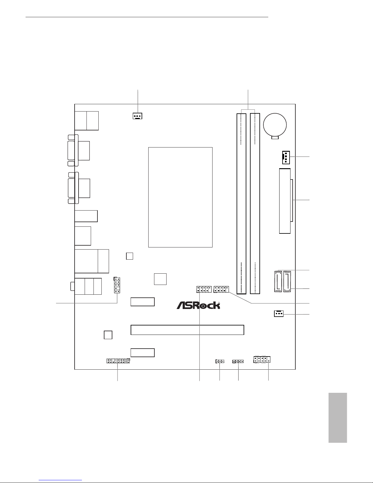
1.3 Motherboard Layout
Ro HS
32Mb
BIOS
ATXPWR1
FSB800
DDR3 _A1 ( 64 bi t, 240- pin m odule )
DDR3 _A2 ( 64 bi t, 240- pin m odule )
SATA3_ 1
LAN
1
CLRCMOS1
PCIE2
1
USB6_7
1
USB4_5
HD_AUDIO1
1
CHA_FAN1
SPEAKER1
1
HDLED RESET
PLED PWRBTN
1
PANEL1
RJ-45 LAN
USB 2.0
T: USB2
B: USB3
SATA3_ 2
CPU_FAN1
TPMS1
1
21
3
4
5
6
7
USB 2.0
T: USB0
B: USB1
PS2
Keyboard/
Mouse
HDMI1
Top:
LINE I N
Cent er:
FRON T
Bott om:
MIC IN
8
CHA_FAN2
USB 3.0
T: USB0
B: USB1
USB 3.0
AUDIO
CODEC
COM1
VGA1
QC5000M
CMOS
Battery
13
PCIE3
PCIE1
12
11
10
9
14
English
6
No. Description
1 CPU Fan Connector (CPU_FAN1)
2 2 x 240-pin DDR3 DIMM Slots (DDR3_A1, DDR3_A2)
3 Chassis Fan Connector (CHA_FAN1)
4 ATX Power Connector (ATXPWR1)
5 SATA3 Connector (SATA3_1)
6 SATA3 Connector (SATA3_2)
7 USB 2.0 Header (USB4_5)
8 Chassis Fan Connector (CHA_FAN2)
9 System Panel Header (PANEL1)
10 Chassis Speaker Header (SPEAKER1)
11 Clear CMOS Jumper (CLRCMOS1)
12 USB 2.0 Header (USB6_7)
13 TPM Header (TPMS1)
14 Front Panel Audio Header (HD_AUDIO1)
QC5000M
7
English
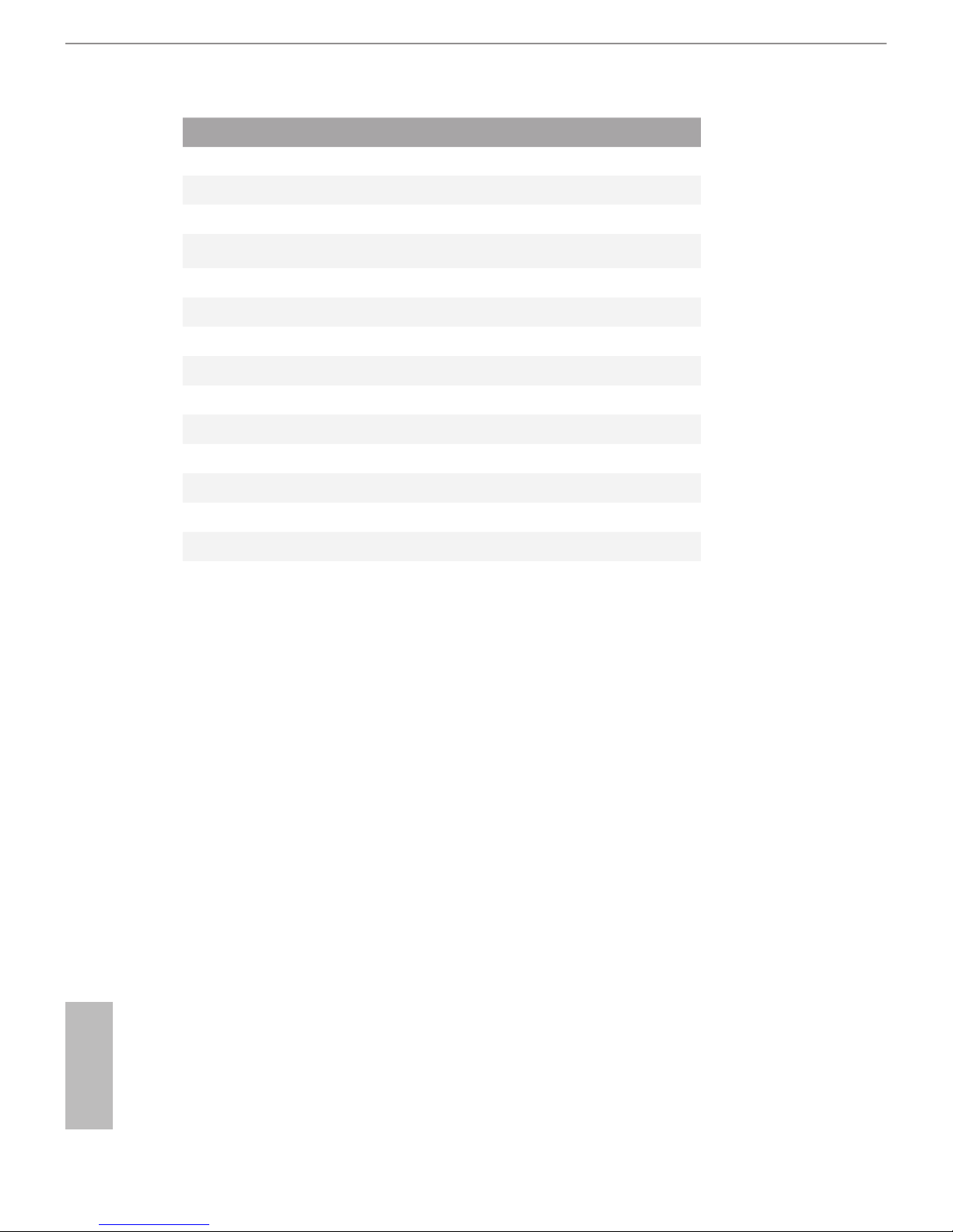
1.4 I/O Panel
No. Description No. Description
1 USB 2.0 Ports (USB01) 7 USB 3.0 Ports (USB3_0_1)
2 LAN RJ-45 Port* 8 HDMI Port
3 Line In (Light Blue)** 9 D-Sub Port
4 Front Speaker (Lime)** 10 COM Port
5 Microphone (Pink)** 11 PS/2 Mouse/Keyboard Port
6 USB 2.0 Ports (USB_2_3)
* ere are two LEDs on each LAN port. Please refer to the table below for the LAN port LED indications.
Activity / Link LED Speed LED
Status Description Status Description
O No Link O 10Mbps connection
Blinking Data Activity Orange 100Mbps connection
On Link Green 1Gbps connection
ACT/LINK LED
SPEED LED
LAN Por t
1 2
6711 8910
4
5
3
English
8
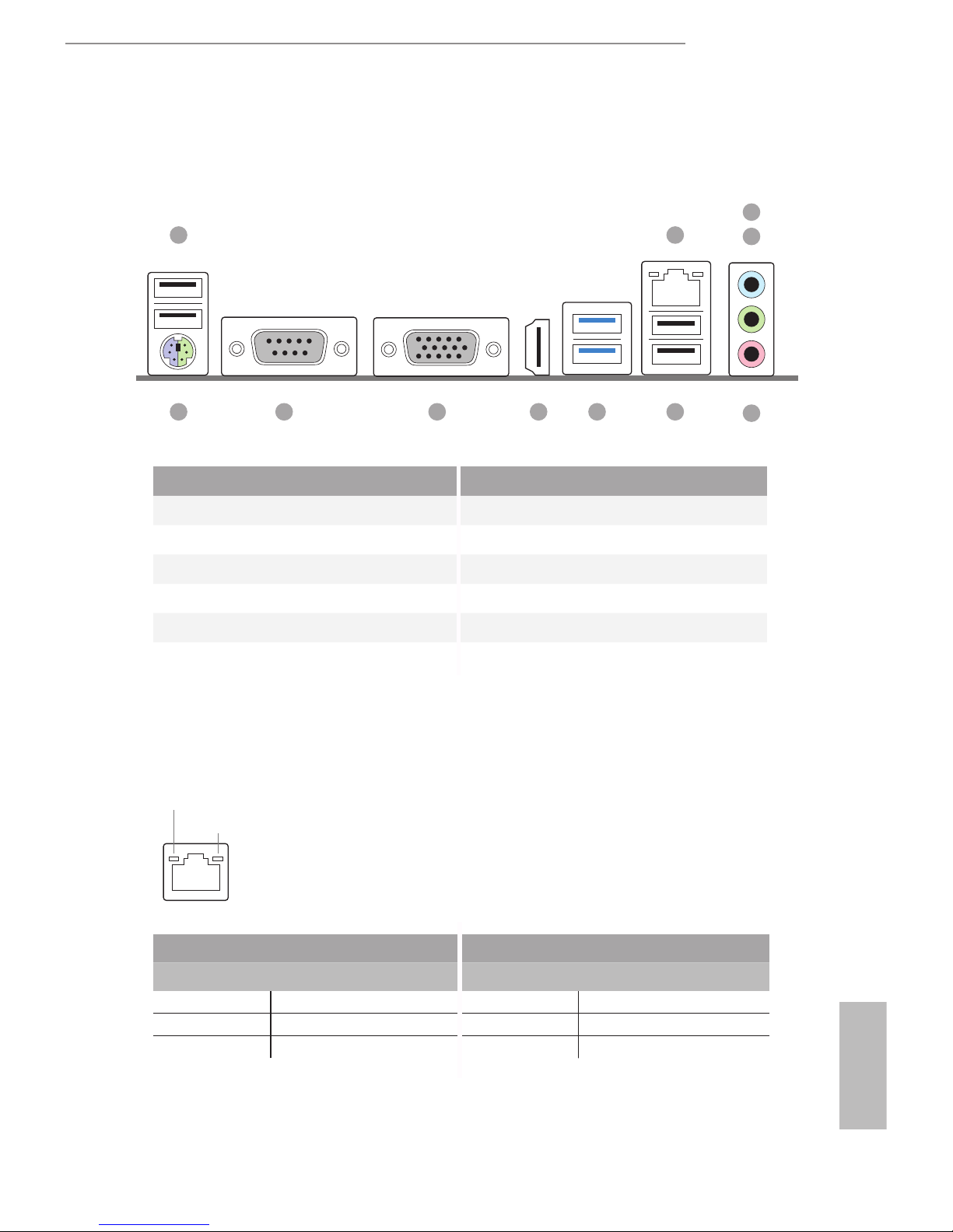
**To congure 7.1 CH HD Audio, it is required to use an HD front panel audio module and enable the multichannel audio feature through the audio driver.
Please set Speaker Conguration to “7.1 Speaker” in the Realtek HD Audio Manager.
Function of the Audio Ports in 7.1-channel Conguration:
Port Function
Light Blue (Rear panel) Rear Speaker Out
Lime (Rear panel) Front Speaker Out
Pink (Rear panel) Central /Subwoofer Speaker Out
Lime (Front panel) Side Speaker Out

QC5000M
9
English
is is a Micro ATX form factor motherboard. Before you install the motherboard,
study the conguration of your chassis to ensure that the motherboard ts into it.
Pre-installation Precautions
Take note of the following precautions before you install motherboard components
or change any motherboard settings.
•
Make sure to unplug the power cord before installing or removing the motherboard.
Failure to do so may cause physical injuries to you and damages to motherboard
components.
•
In order to avoid damage from static electricity to the motherboard’s components,
NEVER place your motherboard directly on a carpet. Also remember to use a grounded
wrist strap or touch a safety grounded object before you handle the components.
•
Hold components by the edges and do not touch the ICs.
•
Whenever you uninstall any components, place them on a grounded anti-static pad or
in the bag that comes with the components.
•
When placing screws to secure the motherboard to the chassis, please do not over-
tighten the screws! Doing so may damage the motherboard.
Chapter 2 Installation
English
10
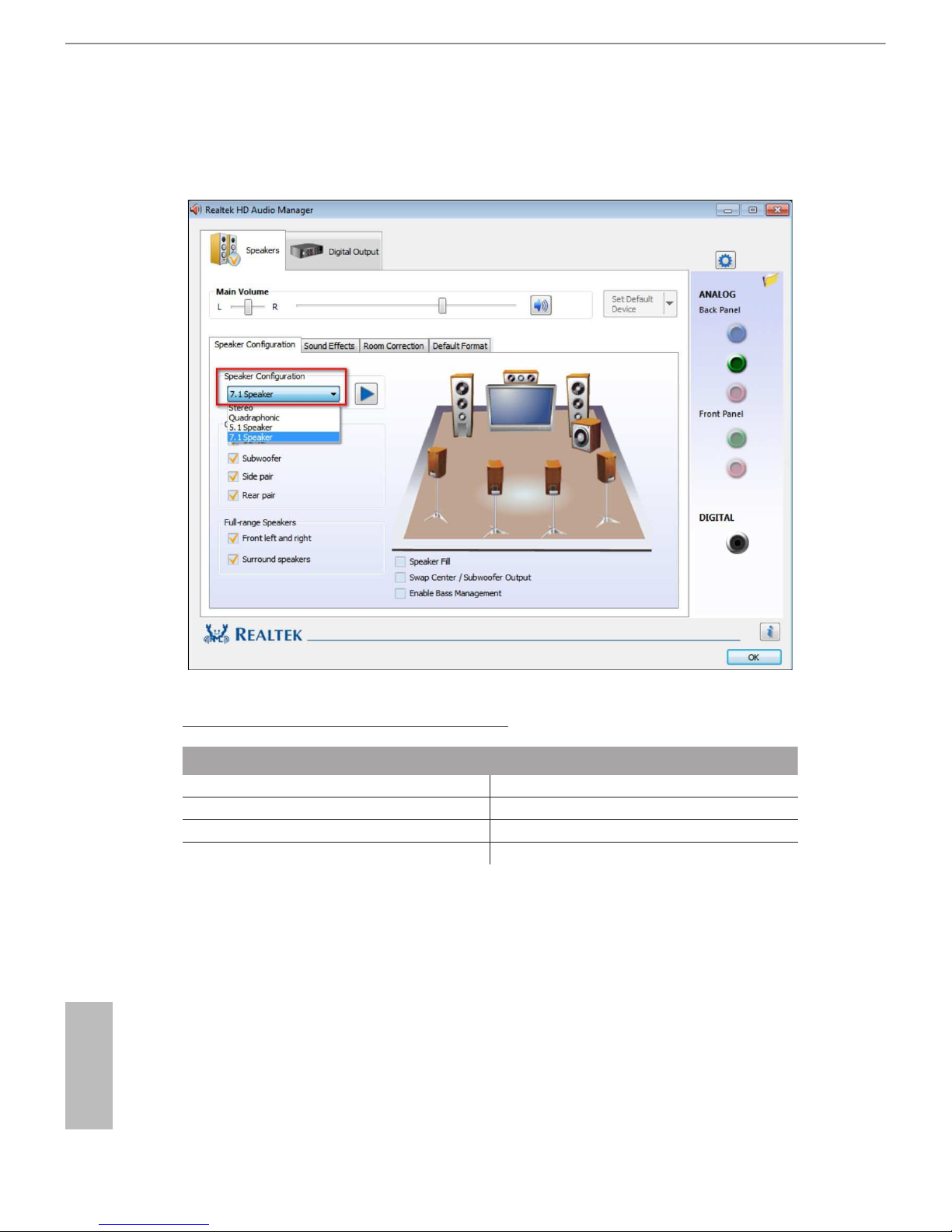
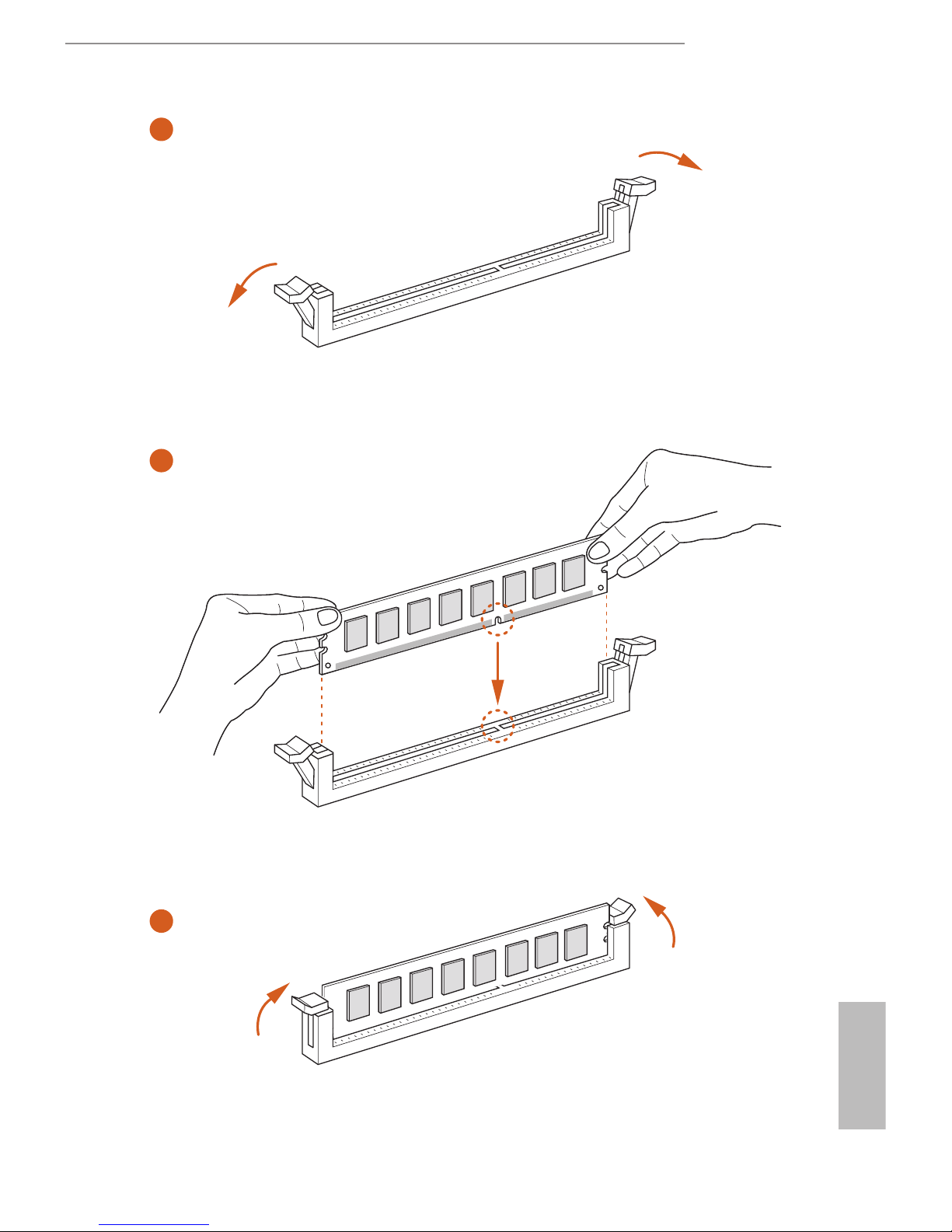
2.1 Installing Memory Modules (DIMM)
is motherboard provides two 240-pin DDR3 (Double Data Rate 3) DIMM slots.
e DIMM only ts in one correct orientation. It will cause permanent damage to
the motherboard and the DIMM if you force the DIMM into the slot at incorrect
orientation.
It is not allowed to install a DDR or DDR2 memory module into a DDR3 slot; otherwise, this motherboard and DIMM may be damaged.
QC5000M
11
English
1
2
3
English
12
2.2 Expansion Slots (PCI Express Slots)
ere are 3 PCI Express slots on the motherboard.
PCIe slots:
PCIE1 (PCIe 2.0 x1 slot) is used for PCI Express x1 lane width cards.
PCIE2 (PCIe 2.0 x16 slot) is used for PCI Express x4 lane width graphics cards.
PCIE3 (PCIe 2.0 x1 slot) is used for PCI Express x1 lane width cards.
Before installing an expansion card, please make sure that the power supply is
switched o or the power cord is unplugged. Please read the documentation of the
expansion card and make necessary hardware settings for the card before you start
the installation.
 Loading...