

Page 1
Copyright Notice:Copyright Notice:
Copyright Notice:
Copyright Notice:Copyright Notice:
No part of this installation guide may be reproduced, transcribed, transmitted, or
translated in any language, in any form or by any means, except duplication of
documentation by the purchaser for backup purpose, without written consent of
ASRock Inc.
Products and corporate names appearing in this guide may or may not be registered
trademarks or copyrights of their respective companies, and are used only for
identification or explanation and to the owners’ benefit, without intent to infringe.
Disclaimer:Disclaimer:
Disclaimer:
Disclaimer:Disclaimer:
Specifications and information contained in this guide are furnished for informational
use only and subject to change without notice, and should not be constructed as a
commitment by ASRock. ASRock assumes no responsibility for any errors or
omissions that may appear in this guide.
With respect to the contents of this guide, ASRock does not provide warranty of any
kind, either expressed or implied, including but not limited to the implied warranties or
conditions of merchantability or fitness for a particular purpose.
In no event shall ASRock, its directors, officers, employees, or agents be liable for
any indirect, special, incidental, or consequential damages (including damages for
loss of profits, loss of business, loss of data, interruption of business and the like),
even if ASRock has been advised of the possibility of such damages arising from any
defect or error in the guide or product.
This device complies with Part 15 of the FCC Rules. Operation is subject to the
following two conditions:
(1) this device may not cause harmful interference, and
(2) this device must accept any interference received, including interference that
may cause undesired operation.
ASRock Website: http://www.asrock.com
Published April 2005
Copyright©2005 ASRock INC. All rights reserved.
ASRock P4V88/P4V88+ Motherboard
EnglishEnglish
EnglishEnglish
English
11
1
11
Page 2
Motherboard LMotherboard L
Motherboard L
Motherboard LMotherboard L
ayoutayout
ayout
ayoutayout
English
EnglishEnglish
EnglishEnglish
22
2
22
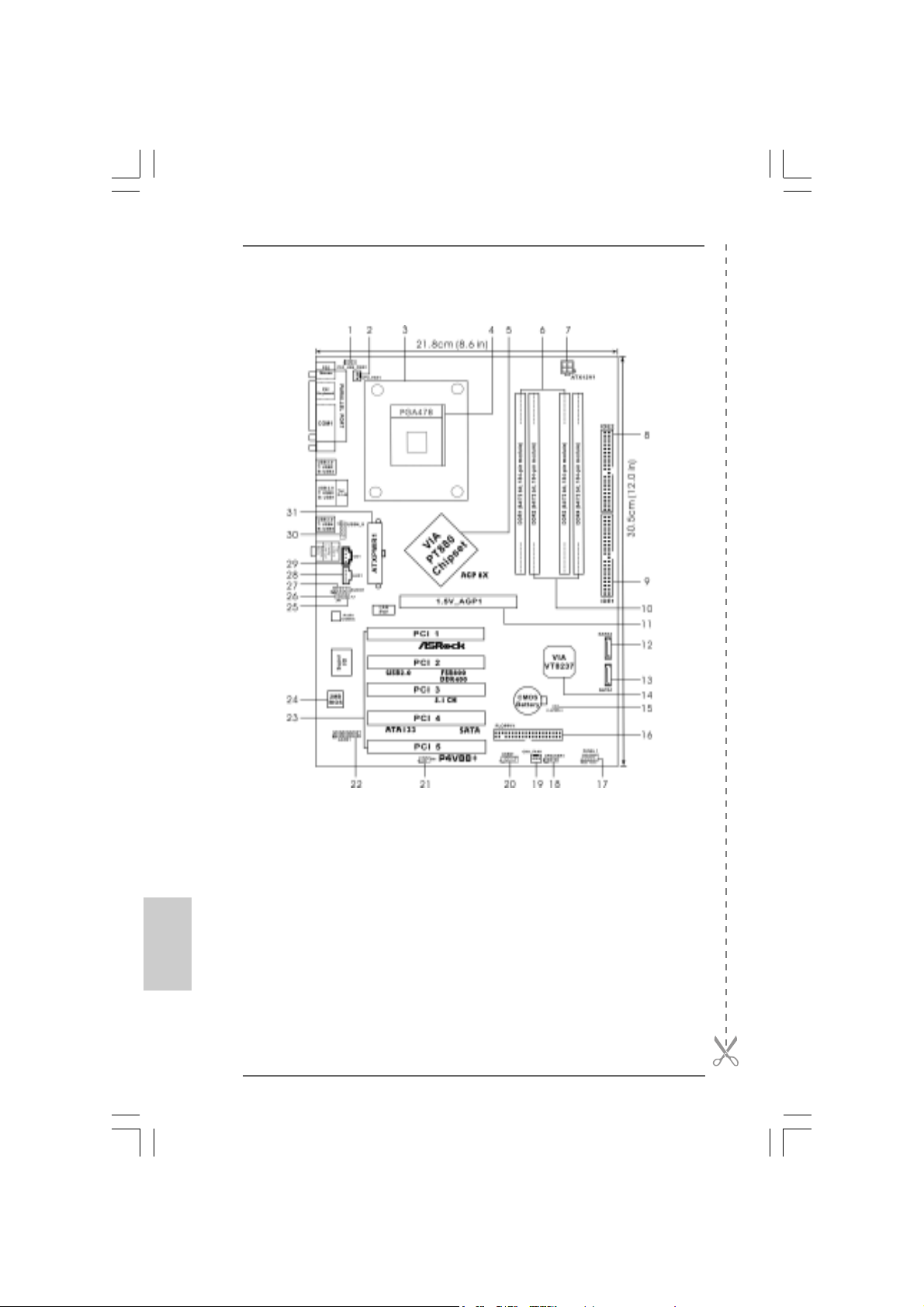
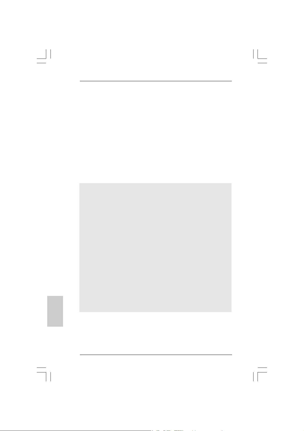
1 PS2_USB_PWR1 Jumper 16 Floppy Connector (FLOPPY1)
2 CPU Fan Connector (CPU_FAN1) 17 System Panel Hea der (PANEL1)
3 CPU Heatsink Retention Module 18 Chassis Speaker Header (SPEAKER 1)
4 CPU Socket 19 Chassis Fan Connector (CHA_FAN1)
5 North Bridge Controller 20 USB 2.0 Header (USB67, Blue)
6 2 x 184-pin DDR DIMM Slots 21 Infrared Module Header (IR1)
(Dual Channel A: DDR1, DDR3; Blue) 22 Game Connector (GAME1)
7 A TX 12V Connector (ATX12V1) 23 5 x PCI Slots (PCI1- 5)
8 Secondary IDE Connector (IDE2, Black) 24 Flash Memory
9 Primary IDE Connector (IDE1, Blue) 25 JL1 Jumper
10 2 x 184-pin DDR DIMM Slots 26 JR1 Jumper
(Dual Channel B: DDR2, DDR4; Black) 27 Front Panel Audio Header (AUDIO1)
11 AGP Slot (1.5V_AGP1) 28 Internal Audio Connector: AUX1 (White)
12 Secondary Serial A T A Conne ctor (SA T A2 ) 29 Internal Audio Connector: CD1 (Black)
13 Primary Serial A T A Conne ctor (SA TA1) 30 Shared USB 2.0 Header (USB4_5, Blue)
14 South Bridge Controller 31 ATX Power Connector (A TXPWR1)
15 Clear CMOS Jumper (CLRCMOS1)
ASRock P4V88/P4V88+ Motherboard
Page 3
TMTM
TM
ASRock I/O PlusASRock I/O Plus
ASRock I/O Plus
ASRock I/O PlusASRock I/O Plus
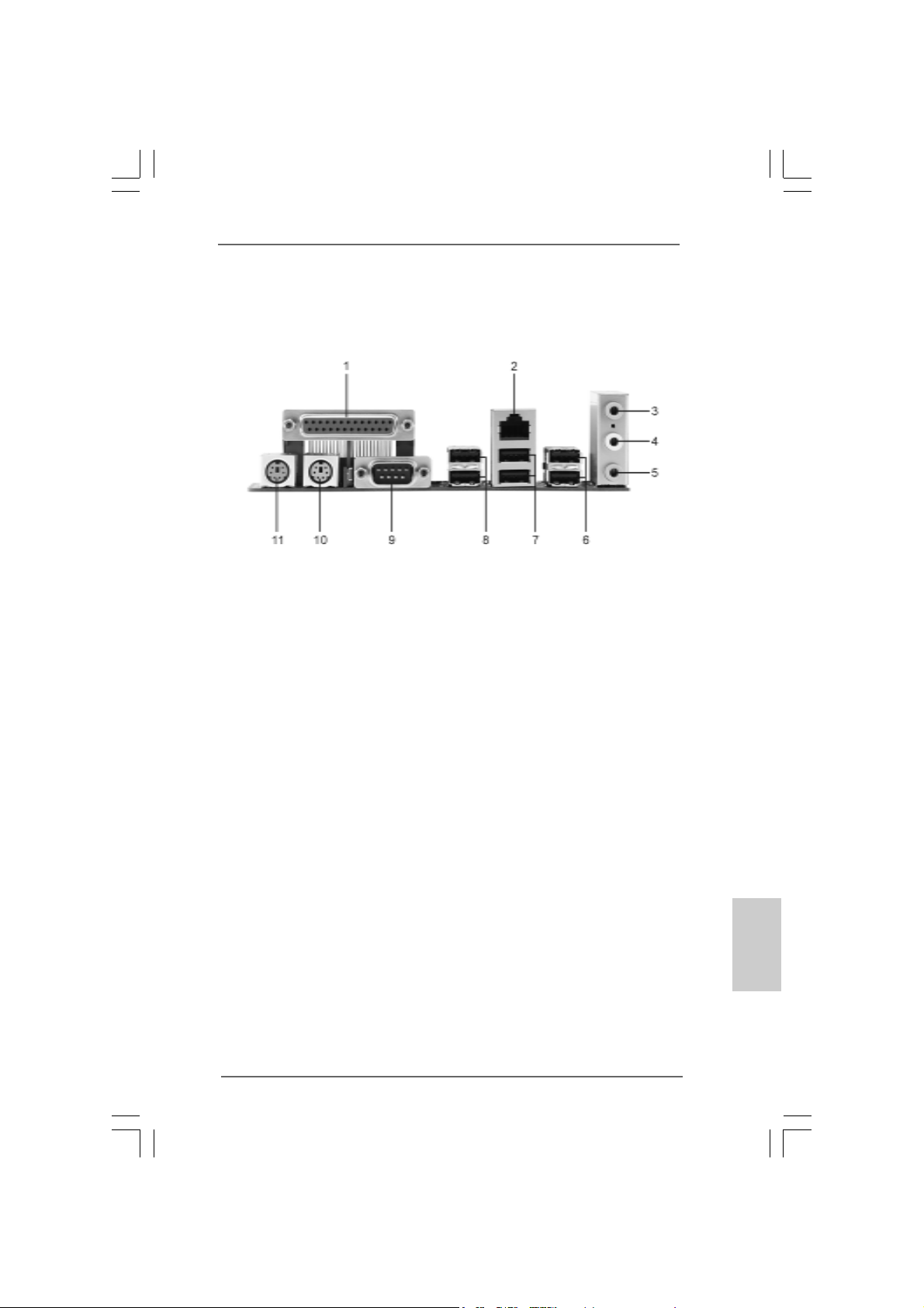
1 Parallel Port 7 USB 2.0 Ports (USB0, USB1)
2 RJ-45 Port 8 USB 2.0 Ports (USB2, USB3)
3 Line In (Light Blue) 9 Serial Port: COM1
4 Line Out (Lime) 10 PS/2 Keyboard Port (Purple)
5 Microphone (Pink) 11 PS/2 Mouse Port (Green)
6 USB 2.0 Ports (USB4, USB5)
TMTM
ASRock P4V88/P4V88+ Motherboard
EnglishEnglish
EnglishEnglish
English
33
3
33
Page 4
1. Introduction1. Introduction
1. Introduction
1. Introduction1. Introduction
Thank you for purchasing ASRock P4V88/P4V88+ motherboard, a reliable motherboard produced under ASRock’s consistently stringent quality control. It delivers
excellent performance with robust design conforming to ASRock’s commitment to
quality and endurance.
This Quick Installation Guide contains introduction of the motherboard and step-bystep installation guide. More detailed information of the motherboard can be found in
the user manual presented in the Support CD.
Because the motherboard specifications and the BIOS software might
be updated, the content of this manual will be subject to change
without notice. In case any modifications of this manual occur, the
updated version will be available on ASRock website without further
notice. You may find the latest memory and CPU support lists on
ASRock website as well.
ASRock website
1.1 Package Contents1.1 Package Contents
1.1 Package Contents
1.1 Package Contents1.1 Package Contents
ASRock P4V88/P4V88+ Motherboard
(ATX Form Factor: 12.0-in x 8.6-in, 30.5 cm x 21.8 cm)
ASRock P4V88/P4V88+ Quick Installation Guide
ASRock P4V88/P4V88+ Support CD
One 80-conductor Ultra ATA 66/100/133 IDE Ribbon Cable
One Ribbon Cable for a 3.5-in Floppy Drive
One Serial ATA (SATA) Cable
One Serial ATA (SATA) HDD Power Cable(Optional)
One ASRock I/O PlusTM Shield
http://www.asrock.com
English
EnglishEnglish
EnglishEnglish
44
4
44
ASRock P4V88/P4V88+ Motherboard
Page 5
1.2 Specifications1.2 Specifications
1.2 Specifications
1.2 Specifications1.2 Specifications
Platform: ATX Form Factor: 12.0-in x 8.6-in, 30.5 cm x 21.8 cm
CPU: Socket 478, supports Intel® Pentium® 4 (Prescott, Northwood,
Willimate) / Celeron® processor
Chipsets: North Bridge:
VIA PT880, FSB @ 800/533/400 MHz,
with Intel® Hyper-Threading Technology ready
(see CAUTION 1)
South Bridge:
VIA VT8237, supports USB 2.0, ATA 133, SATA 1.5Gb/s
Memory: 4 DDR DIMM slots: DDR1, DDR2, DDR3, and DDR4
2 DDR DIMM Slots Support PC3200 (DDR400), Max. 2GB,
4 DDR DIMM Slots Support PC2700 (DDR333) /
PC2100 (DDR266), Max. 3.5GB,
Dual Channel Memory Technology support
(see CAUTION 2)
IDE: IDE1: ATA 133 / Ultra DMA Mode 6
IDE2: ATA 133 / Ultra DMA Mode 6
Support up to 4 IDE devices
Serial ATA: 2 SATA connectors, support up to 1.5Gb/s data transfer rate
Floppy Port: Supports up to 2 floppy disk drives
Audio: 5.1 channels AC’97 Audio
LAN: Speed: 802.3u (10/100 Ethernet), supports Wake-On-LAN
Hardware Monitor: CPU temperature sensing,
Chassis temperature sensing,
CPU overheat shutdown to protect CPU life
(ASRock U-COP)(see CAUTION 3),
CPU fan tachometer,
Chassis fan tachometer,
Voltage monitoring: +12V, +5V, +3V, Vcore
PCI slots: 5 slots with PCI Specification 2.2
AGP slot: 1 AGP slot, supports 1.5V, 8X/4X AGP card (see CAUTION 4)
USB 2.0: 8 USB 2.0 ports:
include 6 ready-to-use USB 2.0 ports on the rear panel,
plus one on-board header supporting 2 extra USB 2.0 ports
(see CAUTION 5)
EnglishEnglish
EnglishEnglish
English
ASRock P4V88/P4V88+ Motherboard
55
5
55
Page 6
English
EnglishEnglish
EnglishEnglish
ASRock I/O PlusTM: 1 PS/2 mouse port, 1 PS/2 keyboard port,
1 serial port: COM1,
1 parallel port: ECP/EPP support,
6 ready-to-use USB 2.0 ports,
1 RJ 45 port,
Audio Jack: Line In / Line Out / Microphone
BIOS: AMI BIOS,
Supports “Plug and Play”,
ACPI 1.1 compliance wake up events,
Supports jumperfree,
SMBIOS 2.3.1 support,
CPU frequency stepless control
(only for advanced users’ reference, see CAUTION 6)
OS: Microsoft® Windows® 98SE / ME / 2000 / XP compliant
CAUTION!
1. About the setting of “Hyper Threading Technology”, please check page 25
in the Support CD.
2. This motherboard supports Dual Cha nnel Me mory Technology. Before you
implement Dual Channel Memory Technology, make sure to read the
installation guide of memory modules on page 8 for proper installation.
3. While CPU overheat is detected, the system will automatically shutdown.
Before you resume the system, please check if the CPU fan on the
motherboard functions properly and unplug the power cord, then plug it
back again. To improve heat dissipation, remember to spray thermal
grease between the CPU a nd the he atsink when you install the PC syste m.
4. Do NOT use a 3.3V AGP card on the AGP slot of this motherboard!
It may cause permanent damage!
5. Power Management for USB 2.0 works fine under Microsoft® Windows® XP
SP1/2000 SP4. It may not work properly under Microsoft® Windows® 98/
ME.
6. Although this motherboard offers stepless control, it is not recommended
to perform over-clocking. Frequencies other than the recommended CPU
bus frequencies may cause the instability of the system or damage the
CPU.
66
6
66
ASRock P4V88/P4V88+ Motherboard
Page 7
2. Installation2. Installation
2. Installation
2. Installation2. Installation
Pre-installation PrecautionsPre-installation Precautions
Pre-installation Precautions
Pre-installation PrecautionsPre-installation Precautions
Take note of the following precautions before you install motherboard
components or change any motherboard settings.
1. Unplug the power cord from the wall socket before touching any
component. Failure to do so may cause severe damage to the
motherboard, peripherals, and/or components.
2. To avoid da maging the motherboard components due to static electricity,
NEVER place your motherboard directly on the carpet or the like. Also
remember to use a grounded wrist strap or touch a safety grounded
object before you handle components.
3. Hold components by the edges and do not touch the ICs.
4. Whenever you uninstall any component, place it on a grounded
antstatic pad or in the bag that comes with the component.
2.1 CPU Installation2.1 CPU Installation
2.1 CPU Installation
2.1 CPU Installation2.1 CPU Installation
STEP 1: Unlock the socket by lifting the lever up to a 90o angle.
STEP 2: Position the CPU directly above the socket such that its marked
corner matches the base of the socket lever.
STEP 3: Carefully insert the CPU into the socket until it fits in place.
The CPU fits only in one correct orientation. DO NOT force the CPU
into the socket to avoid bending of the pins.
STEP 4: When the CPU is in place, press it firmly on the socket while you
push down the socket lever to secure the CPU. The lever clicks on
the side tab to indicate that it is locked.
STEP 5: Install CPU fan and heatsink. For proper installation, please kindly
refer to the instruction manuals of your CPU fan and heatsink vendors.
ASRock P4V88/P4V88+ Motherboard
EnglishEnglish
EnglishEnglish
English
77
7
77
Page 8
2.2 Installation of Memory Modules (DIMM)2.2 Installation of Memory Modules (DIMM)
2.2 Installation of Memory Modules (DIMM)
2.2 Installation of Memory Modules (DIMM)2.2 Installation of Memory Modules (DIMM)
P4V88/P4V88+ motherboard provides four 184-pin DDR (Double Data Rate) DIMM
slots, and supports Dual Channel Memory Technology . For dual cha nnel conf iguration,
you always need to install identical (the same brand, speed, size and chip-type)
DDR DIMM pair in the slots of the same color. In other words, you have to install
identical DDR DIMM pair in Dual Channel A (DDR1 and DDR3; Blue slots; see p.2
No. 6) or identical DDR DIMM pair in Dual Channel B (DDR2 and DDR4; Black slots;
see p.2 No. 10), so that Dual Channel Memory Technology can be activated. This
motherboard also allows you to install four DD R DIMMs for dual channel conf iguration,
and please install identical DDR DIMMs in all four slots. You may refer to the Dual
Channel Memory Configuration Table below.
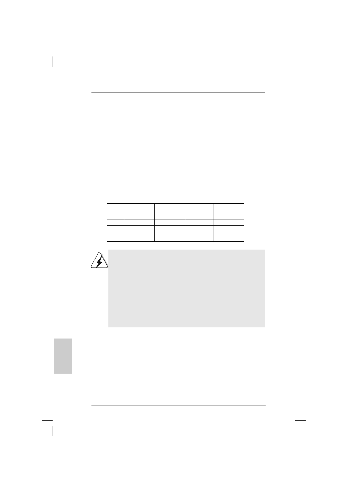
Dual Channel Memory Configurations
DDR1 DDR2 DDR3 DDR4
(Blue Slot) (Black Slot) (Blue Slot) (Black Slot)
(1) Populated - Populated (2) - Populated - Populated
(3) Populated Populated Populated Populated
1. If you want to install two memory modules, for optimal compatibility
and reliability, it is recommended to install them in the slots of the
same color. In other words, install them either in the set of blue slots
(DDR1 and DDR3), or in the set of black slots (DDR2 and DDR4).
2. If only one memory module or three memory modules are installed
in the DDR DIMM slots on this motherboard, it is unable to activate
the Dual Channel Memory T echnology.
3. If a pair of memory modules is NOT installed in the same Dual
Channel, for example, installing a pair of memory modules in DDR1
and DDR2, it is unable to activate the Dual Channel Memory
Technology.
English
EnglishEnglish
EnglishEnglish
88
8
88
ASRock P4V88/P4V88+ Motherboard
Page 9
Installing a DIMMInstalling a DIMM
Installing a DIMM
Installing a DIMMInstalling a DIMM
Please make sure to disconnect power supply before adding or
removing DIMMs or the system components.
STEP 1: Unlock a DIMM slot by pressing the retaining clips outward.
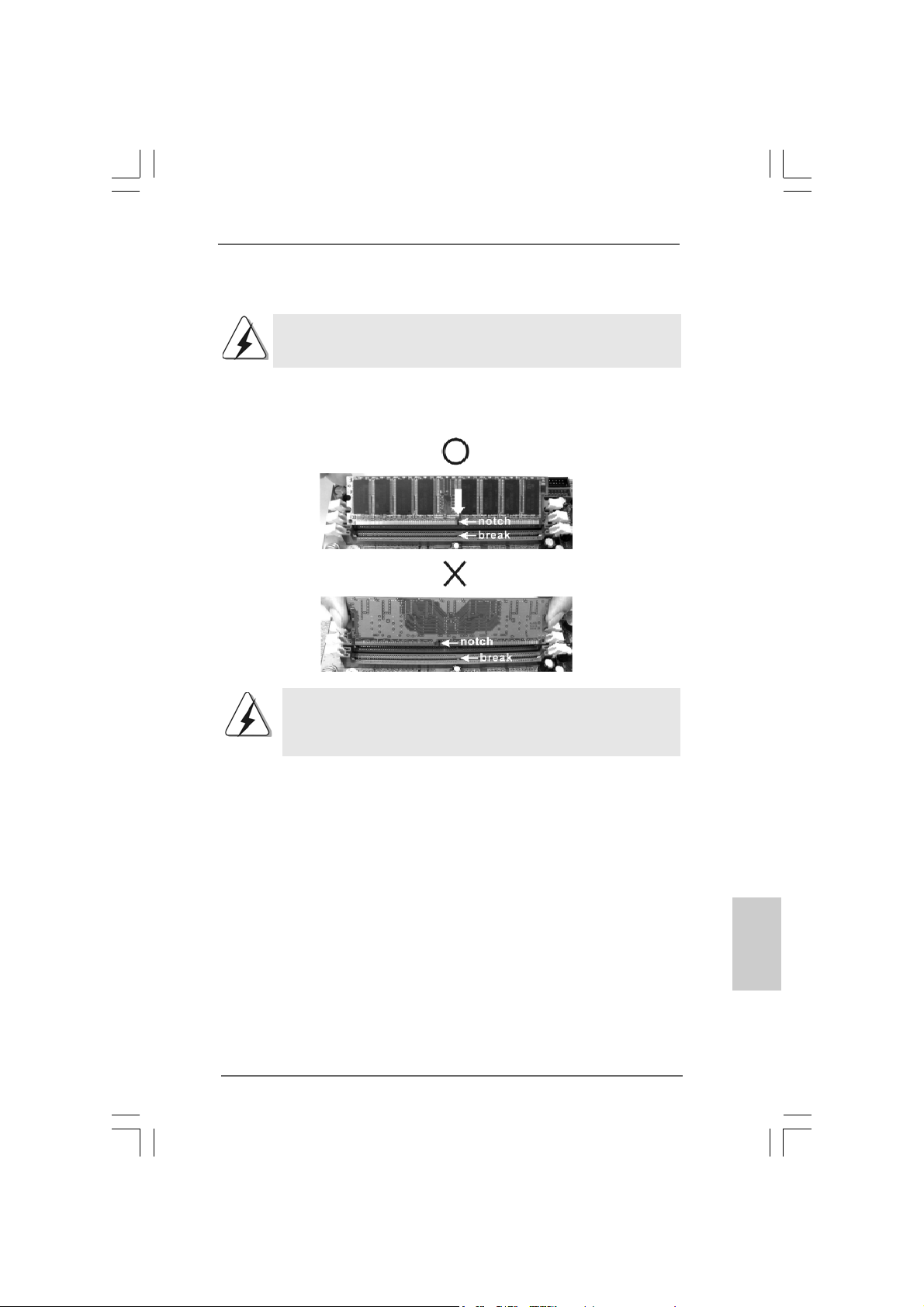
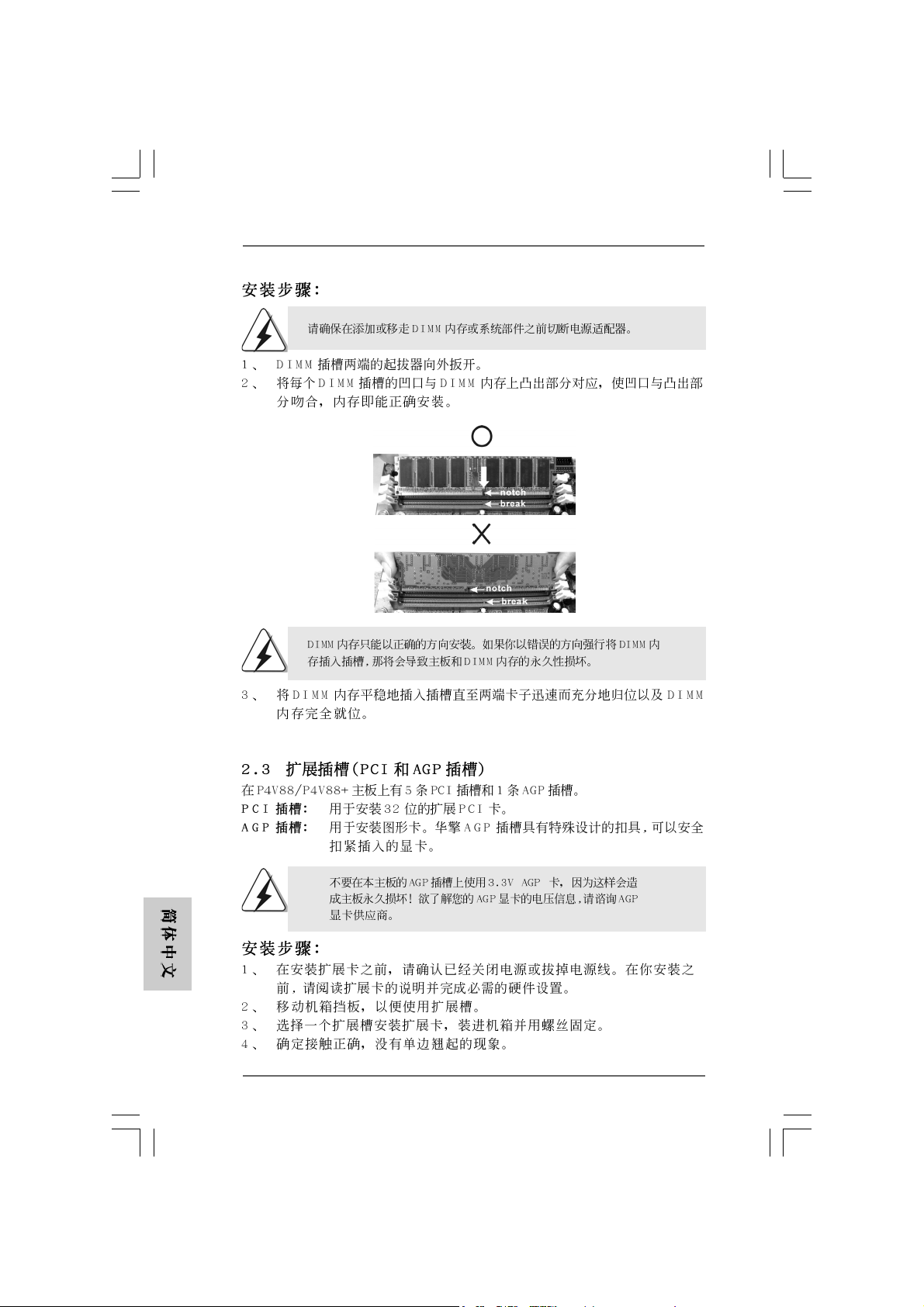
STEP 2: Align a DIMM on the slot such that the notch on the DIMM matches the
break on the slot.
The DIMM only fits in one correct orientation. It will cause permanent
damage to the motherboard and the DIMM if you force the DIMM into the
slot at incorrect orientation.
STEP 3: Firmly insert the DIMM into the slot until the retaining clips at both ends
fully snap back in place and the DIMM is properly seated.
ASRock P4V88/P4V88+ Motherboard
EnglishEnglish
EnglishEnglish
English
99
9
99
Page 10
2.3 Expansion Slots (PCI and AGP Slots)2.3 Expansion Slots (PCI and AGP Slots)
2.3 Expansion Slots (PCI and AGP Slots)
2.3 Expansion Slots (PCI and AGP Slots)2.3 Expansion Slots (PCI and AGP Slots)
There are 5 PCI slots and 1 AGP slot on P4V88/P4V88+ motherboard.
PCI slots: PCI slots are used to install expansion cards that have the 32-bit PCI
interface.
AGP slot: The AGP slot is used to install a graphics card. The ASRock AGP slot has
a special design of clasp that can securely fasten the inserted graphics
card.
Please do NOT use a 3.3V AGP card on the AGP slot of this
motherboard! It may cause permanent damage! For the voltage
information of your AGP card, please check with the AGP card
vendors.
Installing an expansion cardInstalling an expansion card
Installing an expansion card
Installing an expansion cardInstalling an expansion card
STEP 1: Before installing the expansion card, please make sure that the power
supply is switched off or the power cord is unplugged. Please read the
documentation of the expansion card and make necessary hardware
settings for the card before you start the installation.
STEP 2: Remove the bracket facing the slot that you intend to use. Keep the screws
for later use.
STEP 3: Align the card connector with the slot and press firmly until the card is
completely seated on the slot.
STEP 4: Fasten the card to the chassis with screws.
English
EnglishEnglish
EnglishEnglish
1010
10
1010
ASRock P4V88/P4V88+ Motherboard
Page 11
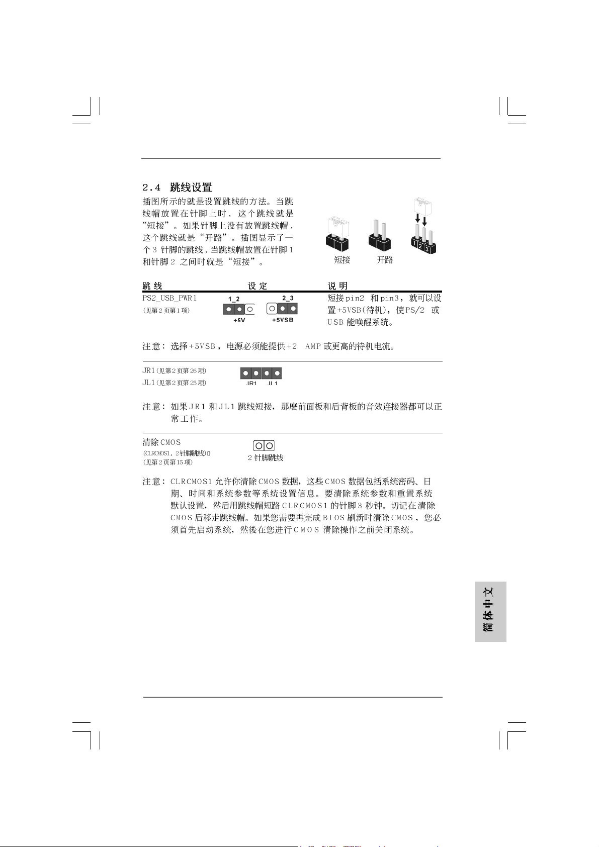
2.4 Jumpers Setup2.4 Jumpers Setup
2.4 Jumpers Setup
2.4 Jumpers Setup2.4 Jumpers Setup
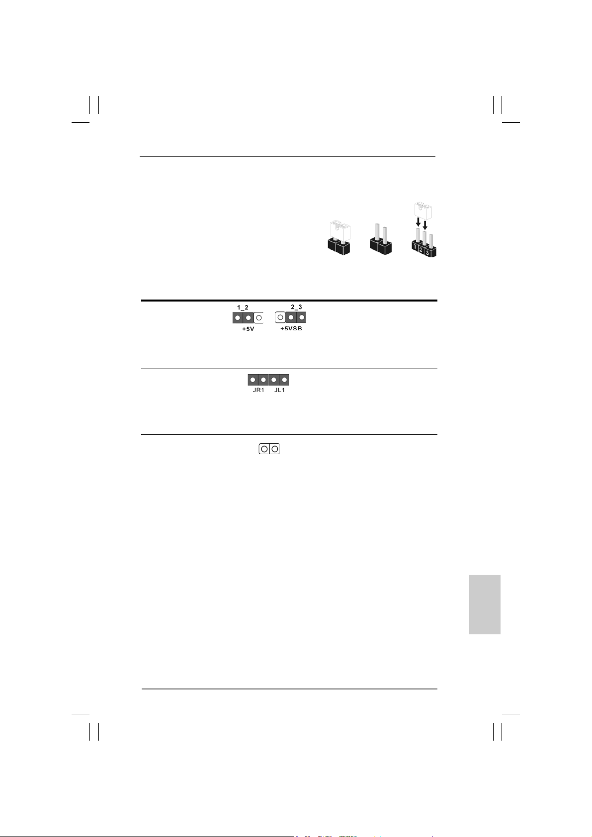
The illustration shows how jumpers are
setup. When the jumper cap is placed on
pins, the jumper is “Short”. If no jumper cap
is placed on pins, the jumper is “Open”. The
illustration shows a 3-pin jumper whose pin1
and pin2 are “Short” when jumper cap is
placed on these 2 pins.
Jumper Setting
PS2_USB_PWR1 Short pin2, pin3 to enable
(see p.2 No. 1) +5VSB (standby) for PS/2
Note: To select +5VSB, it requires 2 Amp and higher standby current provided
by power supply.
JR1(see p.2 No. 26)
JL1(see p.2 No. 25)
Note: If the JL1 and JR1 jumpers are short, both the front panel and the rear panel
audio connectors can work.
Clear CMOS
(CLRCMOS1, 2-pin jumper)
(see p.2 No. 15)
2-pin jumper
Short
or USB wake up events.
Open
Note: CLRCMOS1 allows you to clear the data in CMOS. The data in CMOS includes
system setup information such as system password, date, time, and system
setup parameters. To clear and reset the system parameters to default setup,
please turn off the computer andunplug the power cord, then use a jumper
cap to short the pins on CLRCMOS1 for 3 seconds. Please remember to
remove the jumper cap after cle aring the CMOS. If you need to clear the CMOS
when you just finish updating the BIOS, you must boot up the system first, and
then shut it down before you do the clear-CMOS action.
ASRock P4V88/P4V88+ Motherboard
1111
11
1111
EnglishEnglish
EnglishEnglish
English
Page 12
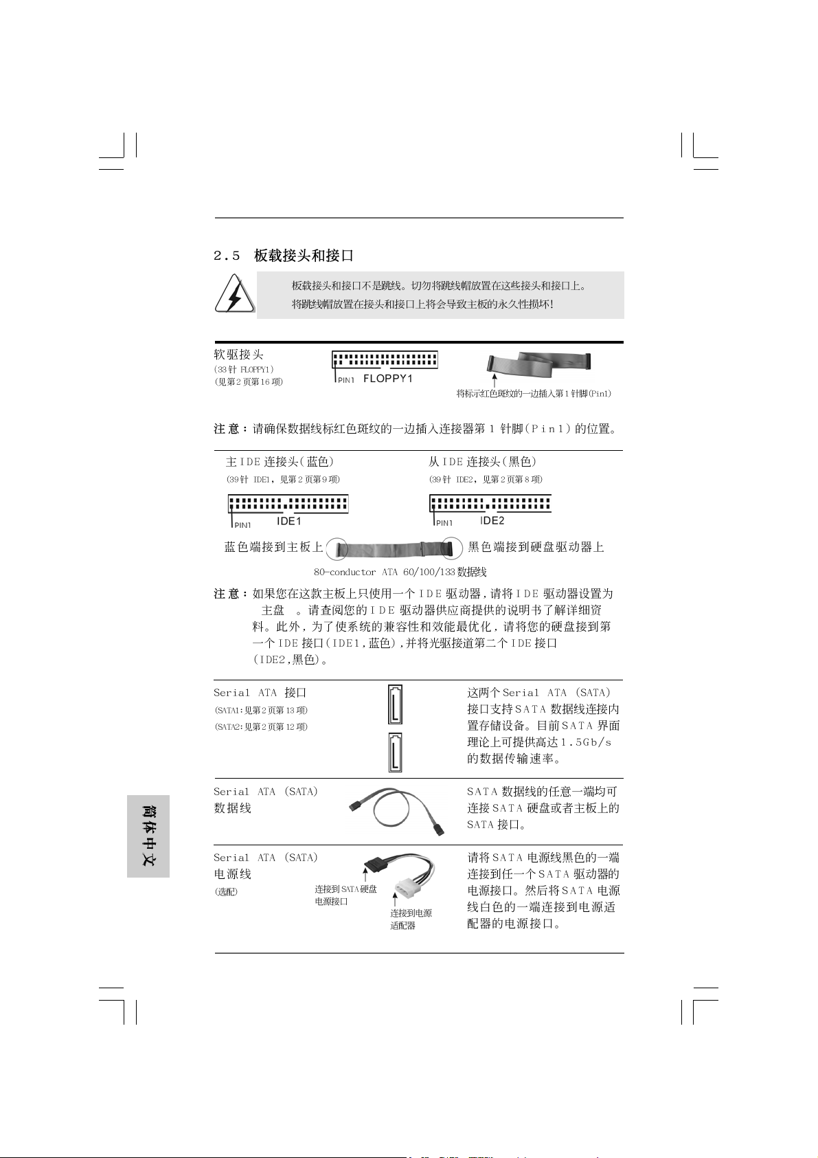
2.5 Onboard Headers and Connectors2.5 Onboard Headers and Connectors
2.5 Onboard Headers and Connectors
2.5 Onboard Headers and Connectors2.5 Onboard Headers and Connectors
Onboard headers and connectors are NOT jumpers. Do NOT place
jumper caps over these headers and connectors. Placing jumper caps
over the headers and connectors will cause permanent damage of the
motherboard!
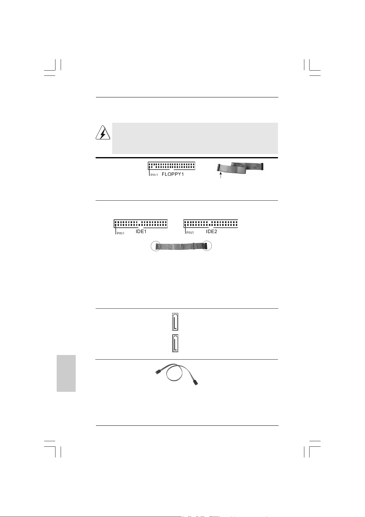
F DD Connector
(33-pin FLOPPY1)
(see p.2 No. 16)
the red-striped side to Pin1
Note: Make sure the red-striped side of the cable is plugged into Pin1 side of the
connector.
Primary IDE Connector (Blue) Secondary IDE Connector (Black)
(39-pin IDE1, see p.2 No. 9) (39-pin IDE2, see p.2 No. 8)
English
EnglishEnglish
EnglishEnglish
connect the blue end
to the motherboard
80-conductor ATA 66/100/133 cable
connect the black end
to the IDE devices
Note: If you use only one IDE device on this motherboard, please set the IDE
device as “Master”. Please refer to the instruction of your IDE device vendor
for the details. Besides, to optimize compatibility and performance, please
connect your hard disk drive to the primary IDE connector (IDE1, blue) and
CD-ROM to the secondary IDE connector (IDE2, black).
Serial ATA Connectors These two Serial ATA (SATA)
(SAT A1: see p.2 No. 13) connectors support SATA data
(SAT A2: see p.2 No. 12) cables for internal storage
SAT A2
SAT A1
devices. The current SATA
interface allows up to 1.5 Gb/s
data transfer rate.
Serial A TA (SATA) Either end of the SATA data ca ble
Data Cable can be connected to the SATA
hard disk or the SA TA conne ctor
on the motherboard.
1212
12
1212
ASRock P4V88/P4V88+ Motherboard
Page 13
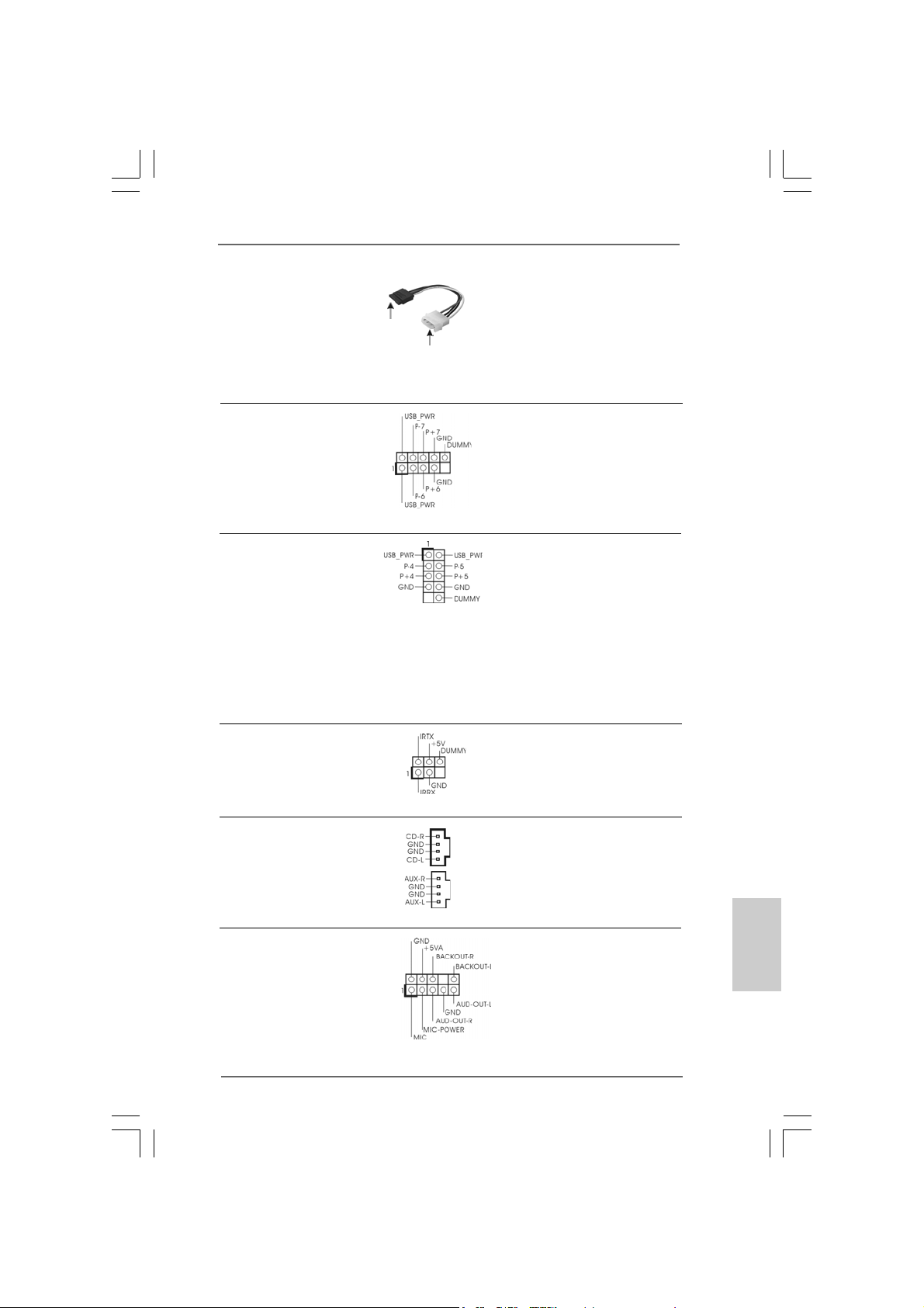
Serial ATA (SATA) Please connect the black end of
Power Cable SATA power cable to the power
(Optional) connector on the drive. Then
connect to the SAT A
HDD power connector
connect to the
power supply
connect the white end of SATA
power cable to the power
connector of the power supply.
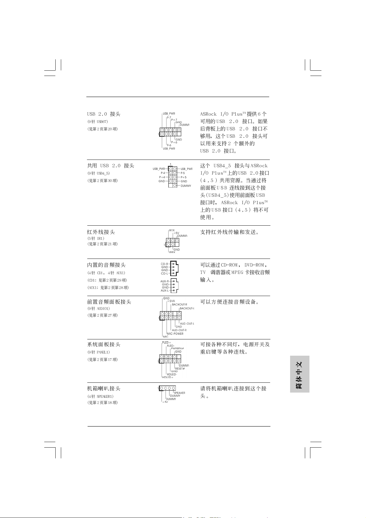
USB 2.0 Header ASRock I/O PlusTM provides you
(9-pin USB67) 6 ready-to-use USB 2.0 ports on
(see p.2 No. 20) the rear panel. If the rear USB
ports are not sufficient, this
USB 2.0 header is available to
support 2 extra USB 2.0 ports.
Shared USB 2.0 Header This USB4_5 connector is shared
(9-pin USB4_5) with the USB 2.0 ports 4,5 on
(see p.2 No. 30) ASRock I/O Plus
TM
. When using
the front panel USB ports by
attaching the front panel USB
cable to this connector
(USB4_5), the USB ports 4,5 on
ASRock I/O PlusTM will not be able
to function.
Infrared Module Header This header supports an optional
(5-pin IR1) wireless transmitting and
(see p.2 No. 21) receiving infrared module.
Internal Audio Connectors These connectors allow you
(4-pin CD1, 4-pin AUX1) to receive stereo audio input
(CD1: see p.2 No. 29) from sound sources such as
(AUX1: see p.2 No. 28) a CD-ROM, D V D-ROM, TV
CD1
AUX1
tuner card, or MPEG card.
Front Panel Audio Header This is an interface for the front
(9-pin AUDIO1) panel audio cable that allows
(see p.2 No. 27) convenient connection and
control of audio devices.
ASRock P4V88/P4V88+ Motherboard
1313
13
1313
EnglishEnglish
EnglishEnglish
English
Page 14
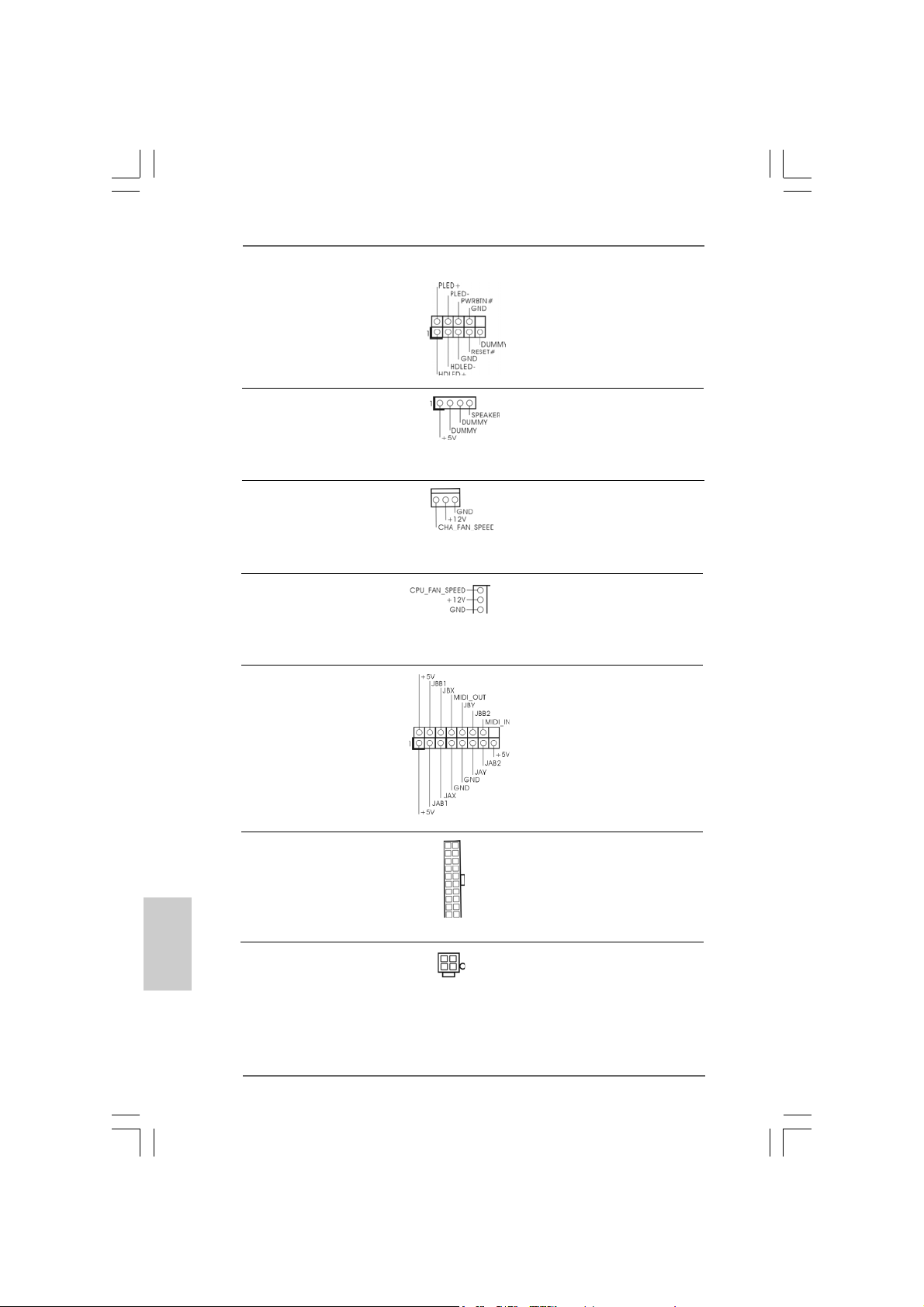
System Panel Header This header accommodates
(9-pin PANEL1) several system front panel
(see p.2 No. 17) functions.
Chassis Speaker Header Please connect the chassis
(4-pin SPEAKER 1) speaker to this header.
(see p.2 No. 18)
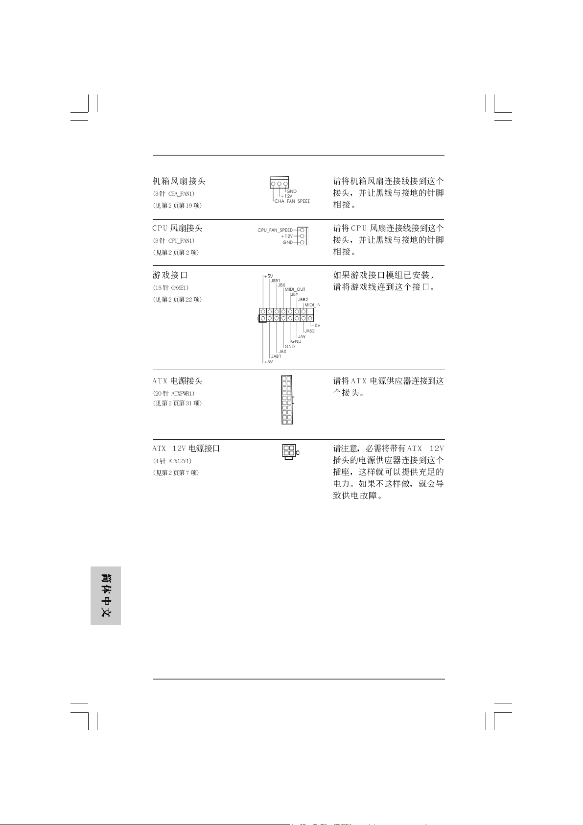
Chassis Fan Connector Please connect the chassis fan
(3-pin CHA_FAN1) cable to this connector and
(see p.2 No. 19) match the black wire to the
ground pin.
CPU Fan Connector Please connect the CPU fan
(3-pin CPU_FAN1) cable to this connector and
(see p.2 No. 2) match the black wire to the
ground pin.
Game Conne ctor Connect a Game cable to this
(15-pin GAME1) connector if the Game port
(see p.2 No. 22) bracket is installed.
English
EnglishEnglish
EnglishEnglish
1414
14
1414
ATX Power Connector Please connect an ATX power
(20-pin ATXPW R1) supply to this connector.
(see p.2 No. 31)
ATX 12V Connector Please note that it is necessary
(4-pin A TX12V1) to connect a power supply with
(see p.2 No. 7) ATX 12V plug to this connector
so that it can provides sufficient
power. Failing to do so will cause
the failure to power up.
ASRock P4V88/P4V88+ Motherboard
Page 15
2.62.6
Serial ASerial A
2.6
Serial A
2.62.6
Serial ASerial A
This motherboard adopts VIA VT8237 southbridge chipset that supports Serial
ATA (SATA) hard disks. You may install SATA hard disks on this motherboard for
internal storage devices. This section will guide you to install the SATA hard disks.
STEP 1: Install the SATA hard disks into the drive bays of your chassis.
STEP 2: Connect the SATA power cable to the SATA hard disk.
STEP 3: Connect one end of the SATA data cable to the motherboard’s SATA
STEP 4: Connect the other end of the SATA data cable to the SATA hard disk.
2.72.7
Hot Plug and Hot Swap FHot Plug and Hot Swap F
2.7
Hot Plug and Hot Swap F
2.72.7
Hot Plug and Hot Swap FHot Plug and Hot Swap F
P4V88/P4V88+ motherboard supports Hot Plug and Hot Swap functions for SATA
Devices.
TT
A (SAA (SA
TT
T
TT
connector.
NOTE
What is Hot Plug Function?
If the SATA HDDs are NOT set for RAID configuration, it is called “Hot
Plug” for the action to insert and remove the SATA HDDs while the
system is still power-on and in working condition.
However, please note that it cannot perform Hot Plug if the OS has
been installed into the SATA HDD.
What is Hot Swap Function?
If SATA HDDs are built as RAID1 then it is called “Hot Swap” for the
action to insert and remove the SATA HDDs while the system is still
power-on and in working condition.
A) Hard Disks InstallationA) Hard Disks Installation
A (SA
T
A) Hard Disks Installation
A (SAA (SA
TT
A) Hard Disks InstallationA) Hard Disks Installation
unctions for SAunctions for SA
unctions for SA
unctions for SAunctions for SA
TT
A HDDsA HDDs
T
A HDDs
TT
A HDDsA HDDs
ASRock P4V88/P4V88+ Motherboard
1515
15
1515
EnglishEnglish
EnglishEnglish
English
Page 16
English
EnglishEnglish
EnglishEnglish
2.82.8
Installing Windows 2000 / Windows XP With RAIDInstalling Windows 2000 / Windows XP With RAID
2.8
Installing Windows 2000 / Windows XP With RAID
2.82.8
Installing Windows 2000 / Windows XP With RAIDInstalling Windows 2000 / Windows XP With RAID
FunctionsFunctions
Functions
FunctionsFunctions
If you want to install Windows 2000 / Windows XP OS on your SATA
HDDs with RAID functions, please follow the below steps.
STEP 1: Make a SATA Driver Diskette.
A. Insert the ASRock Support CD into your optical drive to boot your
system.
B. During POST at the beginning of system boot-up, press <F11> key,and
then a window for boot devices selection appears. Please select CD ROM as the boot device.
C. When you see the message on the screen, “Do you want to generate
Serial ATA driver diskette [YN]?”, press <Y>.
D. Then you will see these messages,
Please insert a diskette into the floppy drive.
WARNING! Formatting the floppy diskette will
lose ALL data in it!
Start to format and copy files [YN]?
Please insert a floppy diskette into the floppy drive, and press <Y>.
E. The system will start to format the floppy diskette and copy SATA
drivers into the floppy diskette.
STEP 2: Use “SATA RAID BIOS” to set RAID configuration.
Before you start to configure the RAID function, you need to check the
installation guide in the Support CD for proper configuration. Please refer
to the document in the Support CD, “Guide to SATA Hard Disks Installation
and RAID Configuration”, which is located in the folder at the following
path: .. \ SATA RAID BIOS
STEP 3: Install Windows 2000 / Windows XP OS on your system.
After making a SATA driver diskette and using “SATA RAID BIOS” to set
RAID configuration, you can start to install Windows 2000 / Windows XP
on your system.
After the installation of Windows 2000 / Windows XP OS, if you want to manage
RAID functions, you are allowed to use both “SATA RAID BIOS” and “VIA RAID Tool”
for RAID configuration. Please refer to the document in the Support CD, “Guide to
SATA Hard Disks Installation and RAID Configuration”, which is located in the folder at
the following path: .. \ SATA RAID BIOS and the document in the support CD, “Guide
to VIA RAID Tool”, which is located in the folder at the following path: .. \ VIA RAID
Tool
1616
16
1616
1. Windows 98 / Windows ME does not support RAID functions.
2. If you want to use “VIA RAID Tool” in Windows environment, please install
SATA drivers from the Support CD again so that “VIA RAID Tool” will be
installed to your system as well.
ASRock P4V88/P4V88+ Motherboard
Page 17
2.92.9
Installing Windows 98 / ME / 2000 / XP Without RAIDInstalling Windows 98 / ME / 2000 / XP Without RAID
2.9
Installing Windows 98 / ME / 2000 / XP Without RAID
2.92.9
Installing Windows 98 / ME / 2000 / XP Without RAIDInstalling Windows 98 / ME / 2000 / XP Without RAID
FunctionsFunctions
Functions
FunctionsFunctions
If you want to install Windows 98 / ME / 2000 / XP on your SATA HDDs without
RAID functions or you want to install Windows 98 / ME / 2000 / XP on your IDE
HDDs instead of SATA HDDs, please refer to the below methods for proper
installation according to the different Windows OS versions.
2.9.1 Installing Windows 98 / ME Without RAID 2.9.1 Installing Windows 98 / ME Without RAID
2.9.1 Installing Windows 98 / ME Without RAID
2.9.1 Installing Windows 98 / ME Without RAID 2.9.1 Installing Windows 98 / ME Without RAID
Functions Functions
Functions
Functions Functions
If you want to install Windows 98 / ME on your SATA HDDs without RAID
functions or you want to install Windows 98 / ME on your IDE HDDs instead
of SATA HDDs, please follow the below steps.
STEP 1: Install Windows 98 / ME OS on your system.
You can start to install Windows 98 / ME on your system directly.
2.9.2 Installing Windows 2000 / XP Without RAID 2.9.2 Installing Windows 2000 / XP Without RAID
2.9.2 Installing Windows 2000 / XP Without RAID
2.9.2 Installing Windows 2000 / XP Without RAID 2.9.2 Installing Windows 2000 / XP Without RAID
Functions Functions
Functions
Functions Functions
If you want to install Windows 2000 / XP on your SATA HDDs without RAID
functions or you want to install Windows 2000 / XP on your IDE HDDs instead
of SATA HDDs, please follow the below steps.
STEP 1: Set Up BIOS.
A. Enter BIOS SETUP UTILITY Advanced screen IDE Configuration.
B. Set the “SATA Operation Mode” option from [RAID] to [non-RAID].
STEP 2: Install Windows 2000 / XP OS on your system.
After setting up BIOS, you can start to install Windows 2000 / XP on your
system.
If you don’t want to set up RAID functions, there is no need to make a SATA
driver diskette.
ASRock P4V88/P4V88+ Motherboard
1717
17
1717
EnglishEnglish
EnglishEnglish
English
Page 18
3. BIOS Information3. BIOS Information
3. BIOS Information
3. BIOS Information3. BIOS Information
The Flash Memory on the motherboard stores BIOS Setup Utility. When you start up
the computer, please press <F2> during the Power-On-Self-Test (POST) to enter
BIOS Setup utility; otherwise, POST continues with its test routines. If you wish to
enter BIOS Setup after POST, please restart the system by pressing <Ctl> + <Alt> +
<Delete>, or pressing the reset button on the system chassis.
The BIOS Setup program is designed to be user-friendly. It is a menu-driven program,
which allows you to scroll through its various sub-menus and to select among the
predetermined choices. For the detailed information about BIOS Setup, please refer
to the User Manual (PDF file) contained in the Support CD.
English
EnglishEnglish
EnglishEnglish
4. Software Suppor4. Software Suppor
4. Software Suppor
4. Software Suppor4. Software Suppor
This motherboard supports various Microsoft® Windows® operating systems: 98 SE/
ME / 2000 / XP. The Support CD that came with the motherboard contains necessary
drivers and useful utilities that will enhance motherboard features.
To begin using the Support CD, insert the CD into your CD-ROM drive. It will display
the Main Menu automatically if “AUTORUN” is enabled in your computer. If the Main
Menu does not appear automatically, locate and double-click on the file
“ASSETUP.EXE” from the BIN folder in the Support CD to display the menus.
t CD informationt CD information
t CD information
t CD informationt CD information
1818
18
1818
ASRock P4V88/P4V88+ Motherboard
Page 19
ASRock P4V88/P4V88+ Motherboard
1919
19
1919
Page 20
® ®
®
2020
20
2020
ASRock P4V88/P4V88+ Motherboard
Page 21
®
®
ASRock P4V88/P4V88+ Motherboard
2121
21
2121
Page 22
2222
22
2222
ASRock P4V88/P4V88+ Motherboard
Page 23
DDR1 DDR2 DDR3 DDR4
( )( )( )( )
(1) - (2) - (3)
ASRock P4V88/P4V88+ Motherboard
2323
23
2323
Page 24
2424
24
2424
ASRock P4V88/P4V88+ Motherboard
Page 25
ASRock P4V88/P4V88+ Motherboard
2525
25
2525
Page 26
2626
26
2626
“ ”
SAT A2
SAT A1
ASRock P4V88/P4V88+ Motherboard
Page 27
CD1
AUX1
ASRock P4V88/P4V88+ Motherboard
2727
27
2727
Page 28
2828
28
2828
ASRock P4V88/P4V88+ Motherboard
Page 29
ASRock P4V88/P4V88+ Motherboard
2929
29
2929
Page 30

3030
30
3030
ASRock P4V88/P4V88+ Motherboard
Page 31

ASRock P4V88/P4V88+ Motherboard
3131
31
3131
Page 32

® ®
3232
32
3232
ASRock P4V88/P4V88+ Motherboard
Page 33

1. Einführung1. Einführung
1. Einführung
1. Einführung1. Einführung
Wir danken Ihnen für den Kauf des ASRock P4V88/P4V88+ Motherboard, ein
zuverlässiges Produkt, welches unter den ständigen, strengen Qualitätskontrollen
von ASRock gefertigt wurde. Es bietet Ihnen exzellente Leistung und robuste s Design,
gemäß der Verpflichtung von ASRock zu Qualität und Halbarkeit.
Diese Schnellinstallationsanleitung führt in das Motherboard und die schrittweise
Installation ein. Details über das Motherboard finden Sie in der Bedienungsanleitung
auf der Support-CD.
Da sich Motherboard-Spezifikationen und BIOS-Software verändern können,
kann der Inhalt dieses Handbuches ebenfalls jederzeit geändert werden. Für
den Fall, dass sich Änderungen an diesem Handbuch ergeben, wird eine neue
Version auf der ASRock-Website, ohne weitere Ankündigung, verfügbar sein.
Die jeweils neueste Liste der unterstützten Speichertypen CPUs finden Sie
ebenfalls auf der Webseite von ASRock.
ASRock-Website: http://www.asrock.com
1.1 Kartoninhalt
ASRock P4V88/P4V88+ Motherboard
(ATX-Formfaktor: 30.5 cm x 21.8 cm; 12.0 Zoll x 8.6 Zoll)
ASRock P4V88/P4V88+ Schnellinstallationsanleitung
ASRock P4V88/P4V88+ Support-CD
Ein 80-adriges Ultra-ATA 66/100/133 IDE-Flachbandk abel
Ein Flachbandkabel für ein 3,5-Zoll-Diskettenlaufwerk
Ein Seriell-ATA- (SATA) Datenkabel
Ein Seriell-ATA (SATA) Festplattennetzkabel (Option)
Ein ASRock I/O Plus
TM
Shield
ASRock P4V88/P4V88+ Motherboard
3333
33
3333
DeutschDeutsch
DeutschDeutsch
Deutsch
Page 34

Deutsch
DeutschDeutsch
DeutschDeutsch
3434
34
3434
1.2 Spezifikationen
Plattform: ATX-Formfaktor: 30.5 cm x 21.8 cm; 12.0 Zoll x 8.6 Zoll
CPU: Socket 478 für Intel® Pentium® 4 (Prescott, Northwood,
Willimate) / Celeron® Prozessoren
Chipsatz: North Bridge:
VIA PT880, FSB @ 800/533/400 MHz,
unterstützt Hyper-Threading Technology
(siehe VORSICHT 1)
South Bridge:
VIA VT8237,
unterstützt USB2.0, ATA 133, SATA 1.5Gb/s
RAM: 4 DDR DIMM Slots: DDR1, DDR2, DDR3, und DDR4
2 DDR DIMM-Steckplätze unterstützen
PC3200 (DDR400), max. 2 GB,
4 DDR DIMM-Steckplätze unterstützen
PC2700 (DDR333) / PC2100 (DDR266), max. 3,5 GB
Unterstützung von Dual-Kanal-Speichertechnologie
(siehe VORSICHT 2)
HDD: IDE1: AT A 133 / Ultra DMA Mode 6
IDE2: ATA 133 / Ultra DMA Mode 6
Unterstützt bis 4 IDE-Geräte
Seriell-ATA: 2 SATA-Anschlüsse, unterstützt bis 1.5 Gb/s
Datenübertragungsrate
Disk.lwk.anschl.: Unterstützt bis 2 Diskettenlaufwerke
Audio: 5.1 Kanal AC’97 Audio
LAN: Speed: 802.3u (10/100 Ethernet),
unterstützt Wake-On-LAN
Hardware Monitor: CPU Temperaturmessung,
Messung der häuseinnentemperatur,
CPU Shutdown bei Überhitzung, schützt die CPU vor dem
Hitzetod (ASRock U-COP)(siehe VORSICHT 3),
Rotationskontrolle für CPU-Lüfter,
Rotationskontrolle für Gehäuse-Lüfter,
Spannungsüberwachung: +12V, +5V, +3V, Vcore
PCI-Slots: 5 Slots nach PCI-Spezifikation 2.2
AGP-Slot : 1x AGP-Slot, unterstützt 1.5V, 8X / 4X AGP-Karten
(siehe VORSICHT 4)
USB 2.0: 8 USB 2.0-Anschlüsse:
Mit 6 betriebsfertigen USB 2.0-Anschlüssen auf der
Rückseite, plus einem integrierten Header mit
Unterstützung von 2 zusätzlichen USB 2.0-Anschlüssen
(siehe VORSICHT 5)
ASRock P4V88/P4V88+ Motherboard
Page 35
ASRock I/O PlusTM: 1 PS/2-Tastaturanschluss, 1 PS/2-Mausanschluss,
1 serieller port: COM 1,
1 paralleler port: Unterstützung für ECP / EPP,
6 betriebsfertigen USB 2.0-Anschlüsse,
1 RJ 45 port,
Audioanschlüsse: Line In / Line Out / Mikrofon
BIOS: AMI legal BIOS mit Unterstützung für “Plug and Play”,
ACPI 1.1-Weckfunktionen,
JumperFree-Modus, SMBIOS 2.3.1,
Schrittloser CPU-Frequenz-Kontrolle (Nur für erfahrene
Anwender empfohlen, siehe VORSICHT 6)
Betriebssysteme: Unterstützt Microsoft® Windows® 98SE / ME / 2000 / XP
VORSICHT!
1. Die Einstellung der “Hyper-Threading Technology”, finden Sie auf Seite
25 des auf der Support-CD enthaltenen Benutzerhandbuches
beschrieben.
2. Dieses Motherboard unterstützt Dual-Kanal-Speichertechnologie. Vor
Implementierung der Dual-Kanal-Speichertechnologie müssen Sie die
Installationsanleitung für die Speichermodule auf Seite 37 zwecks
richtiger Installation gelesen haben.
3. Wird eine Überhitzung der CPU registriert, führt das System einen
automatischen Shutdown durch. Bevor Sie das System neu starten,
prüfen Sie bitte, ob der CPU-Lüfter am Motherboard richtig funktioniert,
und stecken Sie bitte den Stromkabelstecker aus und dann wieder ein.
Um die Wärmeableitung zu verbessern, bitte nicht vergessen, etwas
Wärmeleitpaste zwischen CPU und Kühl körper zu sprühen.
4. Stecken Sie KEINE 3,3V AGP-Karte in den AGP-Steckplatz dieses
Motherboards! Permanente Beschädigung könnte die Folge sein!
5. Das Power Management für USB 2.0 arbeitet unter Microsoft® Windows
XP SP1/2000 SP4 einwandfrei. Unter Microsoft® Windows® 98/ME
könnte es dagegen zu Störungen kommen. Bitte lessen Sie hierzu das
offizielle Microsoft-Dokument.
6. Obwohl dieses Motherboard stufenlose Steuerung bietet, wird Overclocking nicht empfohlen. Frequenzen, die über den für den jeweiligen
Prozessor vorgesehenen liegen, können das System instabil werden
lassen oder die CPU beschädigen.
®
ASRock P4V88/P4V88+ Motherboard
3535
35
3535
DeutschDeutsch
DeutschDeutsch
Deutsch
Page 36

2. Installation
Sicherheitshinweise vor der Montage
Bitte nehmen Sie die folgende Sicherheitshinweise zur Kenntnis, bevor Sie das
Motherboard einbauen oder Veränderungen an den Einstellungen vornehmen.
1. Trennen Sie das System vom Stromnetz, bevor Sie eine Systemkomponente
berühren, da es sonst zu schweren Schäden am Motherboard oder den
sonstigen internen, bzw. externen Komponenten kommen kann.
2. Um Schäden aufgrund von statischer Elektrizität zu vermeiden, das
Motherboard NIEMALS auf einen Teppich o.ä.legen. Denken Sie außerem
daran, immer ein geerdetes Armband zu tragen oder ein geerdetes Objekt
aus Metall zu berühren, bevor Sie mit Systemkomponenten hantieren.
3. Halten Sie Komponenten immer an den Rändern und vermeiden Sie
Berührungen mit den ICs.
4. Wenn Sie Komponenten ausbauen, legen Sie sie immer auf eine antistatische
Unterlage, oder zurück in die Tüte, mit der die Komponente geliefert wurde.
2.1 CPU Installation
Schritt 1: Öffnen Sie den CPU-Sockel, indem sie den Hebel leicht zur Seite und
dann nach oben ziehen, auf einen Winkel von 90°.
Schritt 2: Halten Sie die CPU korrekt ausgerichtet über den Sockel, so dass die
markierte Ecke der CPU zum Hebelgelenk zeigt.
Schritt 3: Drücken Sie die CPU vorsichtig in den Sockel.
Deutsch
DeutschDeutsch
DeutschDeutsch
3636
36
3636
Die CPU sollte problemlos in den Sockel passen. Drücken Sie die CPU
nicht mit Gewalt in den Sockel, damit sich die Pins nicht verbiegen.
Überprüfen Sie die Ausrichtung und suchen nach verbogenen Pins,
sollte die CPU nicht in den Sockel passen.
Schritt 4: Wenn die CPU korrekt im Sockel sitzt, leicht mit dem Finger
draufdrücken und gleichzeitig den Hebel nach unten drücken, bis er
hörbar einrastet.
Schritt 5: Installieren Sie einen aktiven CPU-Kühler, der die gesamte Fläche der
CPU abdeckt und eine ausreichende Wärmeableitung für den von
Ihnen verwendeten CPU-Typ bietet. Weitere Hinweise finden Sie der
Installationsanleitung für Ihren CPU-Kühler.
ASRock P4V88/P4V88+ Motherboard
Page 37

2.2 Installation der Speichermodule (DIMM)
Die Motherboards P4V88/P4V88+ bieten vier 184-pol. DDR (Double Data Rate)
DIMM-Steckplätze und unterstützen die Dual-Kanal-Speichertechnologie. Für die
Dual-Kanalkonfiguration dürfen Sie nur identische (gleiche Marke,
Geschwindigkeit, Größe und gleicher Chiptyp) DDR DIMM-Paare in den
Steckplätzen gleicher Farbe installieren. Mit anderen Worten, sie müssen ein
identisches DDR DIMM-Paar im Dual-Kanal A (DDR1 und DDR3; blaue Steckplätze,
siehe Seite 2 Nr. 6) oder ein identisches DDR DIMM-Paar im Dual-Kanal B (DDR2
und DDR4; schwarze Steckplätze, siehe Seite 2 Nr. 10) installieren, damit die DualKanal-Speichertechnologie aktiviert werden kann. Auf diesem Motherboard
können Sie auch vier DDR DIMMs für eine Dual-Kanalkonfiguration installieren. Auf
diesem Motherboard können Sie auch vier DD R DIMM-Module für eine DualKanalkonfiguration installieren, wobei Sie bitte in allen vier Steckplätzen identische
DDR DIMM-Module installieren. Beziehen Sie sich da b ei auf die nachstehende
Konfigurationstabelle für Dual-Kanalspeicher.
Dual-Kanal-Speicherkonfigurationen
DDR1 DDR2 DDR3 DDR4
(blaue Steckplätze) (schwarze Steckplätze) (blaue Steckplätze) (schwarze Steckplätze)
(1) Bestückt - Bestückt (2) - Bestückt - Bestückt
(3) Bestückt Bestückt Bestückt Bestückt
1. Wenn Sie zwei Speichermodule installieren möchten, verwenden Sie
dazu für optimale Kompatibilität und Stabilität Steckplätze gleicher
Farbe. Installieren Sie die beiden Speichermodule also entweder in
den blauen Steckplätzen (DDR 1 und DDR 3) oder den schwarzen
Steckplätzen (DDR2 und DDR 4).
2. Wenn nur ein Speichermodul oder drei Speichermodule in den DDR
DIMM-Steckplätzen auf diesem Motherboard installiert sind, kann es
die Dual-Kanal-Speichertechnologie nicht aktivieren.
3. Ist ein Speichermodulpaar NICHT im gleichen “Dual-Kanal” installiert,
z.B. ein Speichermodulpaar wird in DDR1 und DDR2 installiert, kann
es die Dual-Kanal-Speichertechnologie nicht aktivieren.
ASRock P4V88/P4V88+ Motherboard
3737
37
3737
DeutschDeutsch
DeutschDeutsch
Deutsch
Page 38

Einsetzen eines DIMM-Moduls
Achten Sie darauf, das Netzteil abzustecken, bevor Sie DIMMs oder
Systemkomponenten hinzufügen oder entfernen.
Schritt 1: Öffnen Sie einen DIMM-Slot, indem Sie die seitlichen Clips nach außen
drücken.
Schritt 2: Richten Sie das DIMM-Modul so über dem Slot aus, dass das Modul mit
der Kerbe in den Slot passt.
Die DIMM-Module passen nur richtig herum eingelegt in die
Steckplätze. Falls Sie versuchen, die DIMM-Module mit Gewalt falsch
herum in die Steckplätze zu zwingen, führt dies zu dauerhaften
Schäden am Mainboard und am DIMM-Modul.
Deutsch
DeutschDeutsch
DeutschDeutsch
3838
38
3838
Schritt 3: Drücken Sie die DIMM-Module fest in die Steck plätze, so dass die
Halteklammern an beiden Enden des Moduls einschnappen und das
DIMM-Modul fest an Ort und Stelle sitzt.
ASRock P4V88/P4V88+ Motherboard
Page 39

2.3 Erweiterungssteckplätze (PCI und AGP-Slots):
Es stehen 5 PCI- und 1 AGP-Slot auf dem P4V88/P4V88+- Motherboard zur
Verfügung.
PCI-Slots: PCI-Slots werden zur Installation von Erweiterungskarten mit dem
32bit PCI-Interface genutzt.
AGP-Slot: Der AGP-Steckplatz dient zur Installation einer Grafikkarte. Der
ASRock AGP-Steckplatz hat speziell entwickelte Klammern, die die
eingefügte Grafikkarte sicher festhalten.
Stecken Sie KEINE 3,3V AGP-Karte in den AGP-Steckplatz dieses
Motherboards! Permanente Beschädigung könnte die Folge sein
Erkundigen Sie sich beim Verkäufer der Grafikkarte nach den
Spannungsdaten für Ihre Grafikkarte.
Einbau einer Erweiterungskarte
Schritt 1: Bevor Sie die Erweiterungskarte installieren, vergewissern Sie sich,
dass das Netzteil ausgeschaltet und das Netzkabel abgezogen ist.
Bitte lesen Sie die Dokumentation zur Erweiterungskarte und nehmen
Sie nötige Hardware-Einstellungen für die Karte vor, ehe Sie mit der
Installation beginnen.
Schritt 2: Entfernen Sie das Abdeckungsblech (Slotblende) von dem
Gehäuseschacht (Slot) , den Sie nutzen möchten und behalten die
Schraube für den Einbau der Karte.
Schritt 3: Richten Sie die Karte über dem Slot aus und drücken Sie sie ohne
Gewalt hinein, bis sie den Steckplatz korrekt ausfüllt.
Schritt 4: Befestigen Sie die Karte mit der Schraube aus Schritt 2.
ASRock P4V88/P4V88+ Motherboard
3939
39
3939
DeutschDeutsch
DeutschDeutsch
Deutsch
Page 40

2.4 Einstellung der Jumper
Die Abbildung verdeutlicht, wie Jumper
gesetzt werden. Werden Pins durch
Jumperkappen verdeckt, ist der Jumper
“Gebrückt”. Werden keine Pins durch
Jumperkappen verdeckt, ist der Jumper
“Offen”. Die Abbildung zeigt einen 3-Pin
Jumper dessen Pin1 und Pin2 “Gebrückt”
sind, bzw. es befindet sich eine JumperKappe auf diesen beiden Pins.
Jumper Einstellun Beschreibung
PS2_USB_PWR1 Überbrücken Sie Pin2, Pin3, um
(siehe S.2 - Nr. 1) +5VSB (Standby) zu setzen
Hinweis: Um +5VSB nutzen zu können, muss das Netzteil auf dieser Leitung 2A
oder mehr leisten können.
JR1(siehe S.2 - Nr. 26)
JL1 (siehe S.2 - Nr. 25)
Hinweis: Sind die Jumper JL1 und JR1 gesetzt funktionieren beide
Audioanschlüsse, Front- und Rückseite.
Gebrückt Offen
und die PS/2 oder USBWeckfunktionen zu aktivieren.
Deutsch
DeutschDeutsch
DeutschDeutsch
4040
40
4040
CMOS löschen
(CLRCMOS1, 2-Pin jumper)
(siehe S.2 - Nr. 15)
Hinweis: CLRCMOS1 erlaubt Ihnen da s Löschen der CMOS-Daten. Diese
beinhalten das System-Passwort, Datum, Zeit und die verschiedenen
BIOS-Parameter. Um die Systemparameter zu löschen und auf die
Werkseinstellung zurückzusetzen, schalten Sie bitte den Computer ab
und entfernen das Stromkabel. Benutzen Sie eine Jumperkappe, um die
Pins an CLRCMOS1 für 3 Sekunden kurzzuschließen. Bitte vergessen
Sie nicht, den Jumper wieder zu entfernen, nachdem das CMOS gelöscht
wurde. Bitte vergessen Sie nicht, den Jumper wieder zu entfernen,
nachdem das CMOS gelöscht wurde. Wenn Sie den CMOS-Inhalt gleich
nach dem Aktualisieren des BIOS löschen müssen, müssen Sie zuerst
das System starten und dann wieder ausschalten, bevor Sie den CMOSInhalt löschen.
ASRock P4V88/P4V88+ Motherboard
2-Pin jumper
Page 41

Integrierte Header und AnschlüsseIntegrierte Header und Anschlüsse
2.5
Integrierte Header und Anschlüsse
Integrierte Header und AnschlüsseIntegrierte Header und Anschlüsse
Integrierte Header und Anschlüsse sind KEINE Jumper. Setzen Sie KEINE
Jumperkappen auf diese He ader und Anschlüsse. Wenn Sie Jumperka ppen
auf Header und Anschlüsse setzen, wird das Motherboard unreparierbar
beschädigt!
Anschluss für das
Floppy-Laufwerk
(33-Pin FLOPPY1)
(siehe S.2 - Nr. 16)
die rotgestreifte Seite auf Stift 1
Hinweis: Achten Sie darauf, dass die rotgestreifte Seite des Kabel mit der Stift 1-
Seite des Anschlusses verbunden wird.
Primärer IDE-Anschluss (blau) Sekundärer IDE-Anschluss (schwarz)
(39-pin IDE1, siehe S.2 - Nr. 9) (39-pin IDE2, siehe S.2 - Nr. 8)
Blauer Anschluss Schwarzer Anschluss
zum Motherboard zur Festplatte
80-adriges A TA 66/100/133-Kabel
Hinweis: Wenn Sie auf diesem Motherboard nur ein IDE-Gerät einsetzen, richten Sie
das IDE-Gerät als “Master” ein. Details entnehmen Sie bitte den
Anweisungen Ihres IDE-Gerätehändlers. Zur Optimierung der Kompatibilität
und Leistung verbinden Sie die Festplatte mit dem primären IDE-Anschluss
(IDE1, blau) und das CD-ROM mit de m sekundären IDE-Anschluss (IDE2,
schwarz).
Seriell-ATA-Anschlüsse Diese beiden Serial ATA-
(SAT A1: siehe S.2 - No. 13) (SATA-)Verbínder
(SAT A2: siehe S.2 - No. 12) unterstützten SATA-Datenkabel
SAT A2
SAT A1
für interne
Massen spe ichergeräte. Die
aktuelle SATA-Schnittstelle
ermöglicht eine
Datenübertragungsrate bis
1,5 Gb/s.
ASRock P4V88/P4V88+ Motherboard
4141
41
4141
DeutschDeutsch
DeutschDeutsch
Deutsch
Page 42

Deutsch
DeutschDeutsch
DeutschDeutsch
Serial A TA- (SAT A-) Sie können beide Enden des
Datenkabel SATA-Datenkabels entweder mit
der SATA-Festplatte oder dem
SATA-Anschluss am Mainboard
verbinden.
Serial A TA- (SAT A-) Verbinden Sie das schwarze
Stromversorgungskabel Ende des SATA-Netzkabels mit
(Option) dem Netzanschluss am Laufwerk.
SATA-HDD-Stromanschluss
Verbindung zum
Verbindung zum
Netzteil
Verbinden Sie dann das weiße
Ende des SATAStromversorgungskabels mit
dem Stromanschluss des
Netzteils.
USB 2.0-Header ASRock I/O PlusTM besitzt 6 Stan
(9-pin USB67) dard-USB 2.0-Anschlüsse auf der
(siehe S.2 - No. 20) Rückseite. W enn die hinteren USB-
Anschlüsse nicht ausreichen,
steht dieser USB 2.0- Header
(USB67) zur Unterstützung von 2
zusätzlichen USB 2.0Anschlüssen zur Verfügung.
Gemeinsam genutzter Dieser USB4_5-Header wird mit
USB 2.0-Header den USB 2.0-Anschlüssen 4,5
(9-pin USB4_5) auf ASRock I/O Plus™
(siehe S.2 - No. 30) gemeinsam genutzt. Bei
Verwendung der vorderseitigen
USB-Anschlüsse durch
Verbinden des vorseitigen USBKabels mit diesem Header
(USB4_5) werden die USBAnschlüsse 4,5 auf ASRock I/O
Plus™ nicht funktionieren.
Anschluss für Dieser Anschluss unterstützt
Infrarot-Modul einen optionalen Infrarot-
(5-Pin IR1) Sender/Empfänger.
(siehe S.2 - No. 21)
4242
42
4242
ASRock P4V88/P4V88+ Motherboard
Page 43

Interne Audio-Anschlüsse Diese ermöglichen Ihnen
(4-Pin CD1, 4-Pin AUX1) Stereo-Signalquellen, wie z. B.
(CD1: siehe S.2 - No. 29) CD-ROM, DVD-ROM, TV -Tuner
(AUX1: siehe S.2 - No. 28) oder MPEG-Karten mit Ihrem
CD1
AUX1
System zu verbinden.
Anschluss für Audio auf Dieses Interface zu einem
der Gehäusevorderseite Audio-Panel auf der Vorderseite
(9-Pin AUDIO1) Ihres Gehäuses, ermöglicht
(siehe S.2 - No. 27) Ihnen eine bequeme
Anschlussmöglichkeit und
Kontrolle über Audio-Geräte.
System Panel Anschluss Dieser Anschluss ist für die
(9-Pin PANEL1) verschiedenen Funktionen der
(siehe S.2 - No. 17) Gehäusefront.
Gehäuselautsprecher-Header Schließen Sie den
(4-pin SPEAKER1) Gehäuselautsprecher an diesen
(siehe S.2 - No. 18) Header an.
Gehäuselüfteranschluss Verbinden Sie das
(3-pin CHA_FAN1) Gehäuselüfterkabel mit diesem
(siehe S.2 - No. 19) Anschluss und passen Sie den
schwarzen Draht dem
Erdungsstift an.
CPU-Lüfteranschluss Verbinden Sie das CPU -
(3-pin CPU_FAN1) Lüfterkabel mit diesem
(siehe S.2 - No. 2) Anschluss und passen Sie den
schwarzen Draht dem
Erdungsstift an.
ASRock P4V88/P4V88+ Motherboard
4343
43
4343
DeutschDeutsch
DeutschDeutsch
Deutsch
Page 44

Game-Anschluss Verbinden Sie ein Game-Kabel
(15-pin GAME1) mit diesem Anschluss, wenn
(siehe S.2 - No. 22) der Game-Anschlusshalter
installiert ist.
ATX-Netz-Header Verbinden Sie die ATX-
(20-pin ATXPW R1) Stromversorgung mit diesem
(siehe S.2 - No. 31) Header.
Anschluss für Beachten Sie bitte, da ss Sie e ine
12V-ATX-Netzteil Stromversorgung mit ATX 12-
(4-pin ATX12V1) Volt-Stecker mit diesem
(siehe S.2 - No. 7) Anschluss verbinden müssen,
damit ausreichend Strom
geliefert werden kann.
Andernfalls reicht der Strom
nicht aus, das System zu starten.
Deutsch
DeutschDeutsch
DeutschDeutsch
4444
44
4444
ASRock P4V88/P4V88+ Motherboard
Page 45

2.62.6
Serial ASerial A
2.6
Serial A
2.62.6
Serial ASerial A
Dieses Mainboard arbeitet mit dem VIA VT8237 Southbridge-Chipsatz, der Serial ATA- (SATA-)
Festplatten unterstützt. Als lokale Datenspeichergeräte können Sie SATA-Laufwerke an dieses
Mainboard anschließen. Dieser Abschnitt zeigt Ihnen, wie Sie die SATA-Festplatten installieren.
SCHRITT 1: Installieren Sie die SATA-Festplatten in den Laufwerkseinschüben
SCHRITT 2: Verbinden Sie das SATA-Netzkabel mit der SATA-Festplatte.
SCHRITT 3: Schließen Sie ein Ende des SATA-Datenkabels am SATA-Anschluss
SCHRITT 4: Schließen Sie das andere Ende des SATA-Datenkabels an die SATA-
2.72.7
Hot-Plug- und Hot-Swap-FHot-Plug- und Hot-Swap-F
2.7
Hot-Plug- und Hot-Swap-F
2.72.7
Hot-Plug- und Hot-Swap-FHot-Plug- und Hot-Swap-F
Das Motherboard P4V88/P4V88+ unterstützt Hot-Plug-Funktion für SATA-Geräte.
TT
AA
- (SA- (SA
TT
A) FA) F
T
A
- (SA
TT
AA
- (SA- (SA
des Gehäuses.
des Motherboards an.
Festplatte an.
HIN WEIS
Was ist die Hot-Plug-Funktion?
Wenn SATA-Festplatten NICHT für RAID-Konfiguration eingestellt
sind, werden sie “Hot-Plug” genannt: Ein Einfügen und Entfernen von
SATA-Festplatten, während das System in Betrieb ist und einwandfrei
läuft.
Was ist die Hot-Swap-Funktion?
Wenn SATA-Festplatten als RAID1 eingebaut sind, werden sie “HotSwap” genannt: Ein Einfügen und Entfernen von SATA-Festplatten,
während das System in Betrieb ist und einwandfrei läuft.
estplatteninstallationestplatteninstallation
T
A) F
estplatteninstallation
TT
A) FA) F
estplatteninstallationestplatteninstallation
unktion für SAunktion für SA
unktion für SA
unktion für SAunktion für SA
TT
AA
-F-F
estplattenestplatten
T
A
-F
estplatten
TT
AA
-F-F
estplattenestplatten
2.82.8
Windows 2000 / Windows XP mit RAID-FunktionalitätWindows 2000 / Windows XP mit RAID-Funktionalität
2.8
Windows 2000 / Windows XP mit RAID-Funktionalität
2.82.8
Windows 2000 / Windows XP mit RAID-FunktionalitätWindows 2000 / Windows XP mit RAID-Funktionalität
installiereninstallieren
installieren
installiereninstallieren
Wenn Sie ein Windows 2000- / Windows XP-Betriebssystem mit RAIDFunktionalität auf lhren SATA-Festplatten möchten, gehen Sie bitte wie folgt vor:
SCHRITT 1: SATA-Treiberdiskette erstellen.
A. Legen Sie die ASRock Support-CD in Ihr optisches Laufwerk,
um Ihr System hochzufahren. (Legen Sie zu diesem Zeitpunkt
KEINE Diskette in das Diskettenlaufwerk ein!)
B. Während des Selbsttests zu Beginn des Systemstarts drücken
Sie die <F11>-Taste – ein Fenster zur Auswahl des Boot Laufwerkes (Startlaufwerk) erscheint. Bitte wählen Sie das CD ROM-Laufwerk als Boot-Laufwerk.
ASRock P4V88/P4V88+ Motherboard
4545
45
4545
DeutschDeutsch
DeutschDeutsch
Deutsch
Page 46

Deutsch
DeutschDeutsch
DeutschDeutsch
C. Die Meldung „Do you want to generate Serial ATA driver diskette
[Y/N]?“ [Serial ATA-Treiberdiskette erstellen [Y/N]?] bestätigen
Sie mit <Y>.
D. Daraufhin werden die Meldungen
Please insert a diskette into the floppy drive.
WARNING! Formatting the floppy diskette will
lose ALL data in it!
Start to format and copy files [Y/N]?
[Bitte legen Sie eine Diskette in das Diskettenlaufwerk ein.
WARNUNG! Das Formatieren der Diskette löscht ALLE darauf
enthaltenen Daten!
Formatieren und Kopieren der Dateien starten [Y/N]?]
angezeigt. Legen Sie bitte eine Diskette in das
Diskettenlaufwerk ein und drücken Sie <Y>.
E. Das System beginnt mit dem Formatieren der Diskette und kopiert
die SATA-Treiber auf die Diskette.
SCHRITT 2: „SATA RAID BIOS“ zum Festlegen der RAID-
Konfiguration verwenden.
Bevor Sie mit der Konfiguration der RAID-Funktionalität beginnen,
müssen Sie in der Installationsanleitung auf der Support-CD
hinsichtlich der richtigen Komfiguration nachlesen. Bitte lesen Sie
dazu das Dokument „Anleitung zur SATA-Festplatteninstallation und
RAID-Konfiguration“, das sich in folgendem Ordner auf der SupportCD befindet: .. \ SAT A RAID BIOS
SCHRITT 3: Installieren Sie Windows 2000 / Windows XP in Ihrem
System.
Nachdem Sie eine SATA-Treiberdiskette angelegt und die RAIDKonfiguration mit „SATA RAID BIOS“ durchgeführt haben, können Sie
mit der Installation von Windows 2000 / Windows XP in Ihrem System
beginnen.
Nach der Installation von Windows 2000 / Windows XP können Sie sowohl „SATA
RAID BIOS“ als auch das „VIA RAID Tool“ zur RAID-Konfiguration und zur
Verwaltung der RAID-Funktionalität verwenden. Bitte lesen Sie dazu das
Dokument „Anleitung zur SATA-Festplatteninstallation und RAID-Konfiguration“,
das sich in folgendem Ordner auf der Support-CD befindet: .. \ SATA RAID BIOS
Lesen Sie bitte auch das Dokument „Anleitung zum VIA RAID Tool“, das sich in
diesem Ordner der Support-CD befindet: .. \ VIA RAID Tool
4646
46
4646
1. Unter Windows 98 / Windows ME wird die RAID-Funktionalität nicht unterstützt.
2. Wenn Sie das „VIA RAID Tool“ unter Windows benutzen möchten, installieren Sie
die SATA-Treiber erneut von der Support-CD, so dass das „VIA RAID Tool“
ebenfalls auf Ihrem System installiert wird.
ASRock P4V88/P4V88+ Motherboard
Page 47

2.92.9
Windows 98 / ME / 2000 / XP ohne RAID-FunktionalitätWindows 98 / ME / 2000 / XP ohne RAID-Funktionalität
2.9
Windows 98 / ME / 2000 / XP ohne RAID-Funktionalität
2.92.9
Windows 98 / ME / 2000 / XP ohne RAID-FunktionalitätWindows 98 / ME / 2000 / XP ohne RAID-Funktionalität
installiereninstallieren
installieren
installiereninstallieren
Wenn Sie Windows 98 / ME / 2000 / XP ohne RAID-Funktionalität auf Ihren SATAFestplatten installieren oder Windows 98 / ME / 2000 / XP
statt auf SATA-Festplatten auf IDE-Festplatten installieren möchten, halten Sie sich
bitte an die nachstehend aufgeführten Vorgehensweisen für die
unterschiedlichen Windows-Betriebssystemversionen.
2.9.12.9.1
2.9.1
2.9.12.9.1
installieren installieren
installieren
installieren installieren
Wenn Sie Windows 98 / ME ohne RAID-Funktionalität auf Ihren SATAFestplatten installieren oder Windows 98 / ME statt auf SATA-Festplatten
auf IDE-Festplatten installieren möchten, gehen Sie bitte wie folgt vor:
SCHRITT 1: Installieren Sie Windows 98 / ME.
2.9.22.9.2
2.9.2
2.9.22.9.2
Wenn Sie Windows 2000 / XP ohne RAID-Funktionalität auf Ihren
SATA-Festplatten installieren oder Windows 2000 / XP statt auf
SATA-Festplatten auf IDE-Festplatten installieren möchten, gehen Sie bitte
wie folgt vor:
SCHRITT 1: BIOS einrichten.
SCHRITT 2: Installieren Sie Windows 2000 / XP.
Windows 98 / ME ohne RAID-FunktionalitätWindows 98 / ME ohne RAID-Funktionalität
Windows 98 / ME ohne RAID-Funktionalität
Windows 98 / ME ohne RAID-FunktionalitätWindows 98 / ME ohne RAID-Funktionalität
Sie mit der Installation von Windows 98 / ME beginnen.
Windows 2000 / XP ohne RAID-FunktionalitätWindows 2000 / XP ohne RAID-Funktionalität
Windows 2000 / XP ohne RAID-Funktionalität
Windows 2000 / XP ohne RAID-FunktionalitätWindows 2000 / XP ohne RAID-Funktionalität
installiereninstallieren
installieren
installiereninstallieren
A. Rufen Sie das BIOS SETUP UTILITY auf, wählen Sie den
„Advanced“-Bildschirm (Erweitert), dann „IDE Configuration“ (IDE Konfiguration).
B. Schalten Sie die Option “SATA Operation Mode“ (SATA Betriebsmodus) von [RAID] auf [non-RAID] (nicht-RAID) um.
Nach Einrichten des BIOS können Sie mit der Installation von
Windows 2000 / XP beginnen.
Falls Sie die RAID-Funktionalität nicht einrichten möchten, müssen Sie keine
SATA-Treiberdiskette erstellen.
ASRock P4V88/P4V88+ Motherboard
4747
47
4747
DeutschDeutsch
DeutschDeutsch
Deutsch
Page 48

3. BIOS-Information3. BIOS-Information
3. BIOS-Information
3. BIOS-Information3. BIOS-Information
Das Flash Memory dieses Motherboards speichert das Setup-Utility. Drücken Sie
<F2> während des POST (Power-On-Self-Test) um ins Setup zu gela ngen, ansonsten
werden die Testroutinen weiter abgearbeitet. Wenn Sie ins Setup gelangen wollen,
nachdem der POST durchgeführt wurde, müssen Sie das System über die
Tastenkombination <Ctrl> + <Alt> + <Delete> oder den Reset-Knopf auf der
Gehäusevorderseite, neu starten. Natürlich können Sie einen Neustart auch
durchführen, indem Sie das System kurz ab- und danach wieder anschalten.
Das Setup-Programm ist für eine bequeme Bedienung entwickelt worden. Es ist
ein menügesteuertes Programm, in dem Sie durch unterschiedliche Untermenüs
scrollen und die vorab festgelegten Optionen auswählen können. Für detaillierte
Informationen zum BIOS-Setup, siehe bitte das Benutzerhandbuch (PDF Datei) auf
der Support CD.
Deutsch
DeutschDeutsch
DeutschDeutsch
4. Software Suppor4. Software Suppor
4. Software Suppor
4. Software Suppor4. Software Suppor
Dieses Motherboard unterstützt eine Reiche von Microsoft Windows
Betriebssystemen: 98 SE / ME / 2000 / XP. Die Ihrem Motherboard beigefügte
Support-CD enthält hilfreiche Software, Treiber und Hilfsprogramme, mit denen Sie
die Funktionen Ihres Motherboards verbessern können Legen Sie die Support-CD
zunächst in Ihr CD-ROM-Laufwerk ein. Der Willkommensbildschirm mit den
Installationsmenüs der CD wird automatisch aufgerufen, wenn Sie die “Autorun”Funktion Ihres Systems aktiviert haben.
Erscheint der Wilkommensbildschirm nicht, so “doppelklicken” Sie bitte auf das File
ASSETUP.EXE im BIN-Verzeichnis der Support-CD, um die Menüs aufzurufen.
Das Setup-Progra mm soll es Ihnen so le icht wie möglich ma chen. Es ist menügesteuert,
d.h. Sie können in den verschiedenen Untermenüs Ihre Auswahl treffen und die
Programme werden dann automatisch installiert.
t CD informationt CD information
t CD information
t CD informationt CD information
4848
48
4848
ASRock P4V88/P4V88+ Motherboard
Page 49

1. Introduction1. Introduction
1. Introduction
1. Introduction1. Introduction
Merci pour votre achat d’une carte mère ASRock P4V88/P4V88+, une carte mère
très fiable produite selon les critères de qualité rigoureux de ASRock. Elle offre des
performances excellentes et une conception robuste conformément à l’engagement
d’ASRock sur la qualité et la fiabilité au long terme.
Ce Guide d’installation rapide présente la carte mère et constitue un guide
d’installation pas à pas. Des informations plus détaillées concernant la carte mère
pourront être trouvées dans le manuel l’utilisateur qui se trouve sur le CD
d’assistance.
Les spécifications de la carte mère et le BIOS ayant pu être mis à jour,
le contenu de ce manuel est sujet à des changements sans notification.
Au cas où n’importe qu’elle modification intervenait sur ce manuel, la
version mise à jour serait disponible sur le site web ASRock sans
nouvel avis. Vous pouvez également trouver la dernière liste des
mémoires et microprocesseurs pris en charge sur le site web d’ASRock.
Site web ASRock, http://www.asrock.com
1.1 Contenu du paquet
Carte mère ASRock P4V88/P4V88+
(Facteur de forme ATX : 12.0 pouces x 8.6 pouces, 30.5 cm x 21.8 cm)
Guide d’installation rapide ASRock P4V88/P4V88+
CD de soutien ASRock P4V88/P4V88+
Un câble ruban IDE Ultra ATA 66/100/133 80 conducteurs
Un câble ruban pour un lecteur de disquettes 3,5 pouces
Un câble de données Serial ATA (SATA)
Un cordon d’alimentation DD série ATA (SATA) (en option)
Un écra n ASRock I/O Plus
TM
ASRock P4V88/P4V88+ Motherboard
4949
49
4949
çaisçais
çaisçais
çais
FranFran
FranFran
Fran
Page 50
Français
FrançaisFrançais
FrançaisFrançais
1.2 Spécifications1.2 Spécifications
1.2 Spécifications
1.2 Spécifications1.2 Spécifications
Format: Facteur de forme ATX :
12.0 pouces x 8.6 pouces, 30.5 cm x 21.8 cm
CPU: Socket 478 pour processeurs Intel® Pentium® 4 (Prescott,
Northwood, Willimate) / Celeron
Chipsets: North Bridge:
VIA PT880, FSB @ 800/533/400 MHz,
supporte la technologie Hyper-Threading
(voir ATTENTION 1)
South Bridge:
VIA VT8237, supporte USB 2.0, ATA 133, SATA 1.5Go/s
Mémoire: 4 slots DIMM DDR: DDR1, DDR2, DDR3, et DDR4
2 emplacements DIMM DDR prenant en charge
PC3200 (DDR400), Maxi. 2 Go,
4 emplacements DIMM DDR prenant en charge
PC2700 (DDR333) / PC2100 (DDR 266), Maxi. 3,5 Go
Compatible avec la Technologie de Mémoire à Canal Double
(voir ATTENTION 2)
IDE: IDE1: ATA133 / Ultra DMA Mode 6
IDE2: ATA133 / Ultra DMA Mode 6
Prend en charge jusqu’à 4 périphériques IDE
Série ATA: 2 connecteurs SATA, prennent en charge un taux de transfert
jusqu’à 2 lecteurs de disquettes
Audio: 5.1 canaux audio AC’97;
LAN: Vitesse: 802.3u (Ethernet 10/100), support du Wake-On-LAN
Surveillance Système:
Mesure de la température CPU,
Mesure de la température du châssis,
Coupure auto du CPU en cas de surchauffe pour protéger le CPU
(ASRock U-COP)(voir ATTENTION 3),
Tachymètre de ventilateur CPU,
Tachymètre de ventilateur de châssis,
Surveillance du voltage: +12V, +5V, +3V, Vcore
Slots PCI: 5 slots PCI spécification 2.2
Slot AGP: 1 slot AGP, support des cartes AGP 1.5V, 8X / 4X
(voir ATTENTION 4)
USB 2.0 : 8 ports USB 2.0 :
avec 6 ports USB 2.0 prêts à l’emploi sur le panneau arrière,
plus une barrette sur carte prenant en charge 2 ports USB 2.0
supplémentaires (voir ATTENTION 5)
®
5050
50
5050
ASRock P4V88/P4V88+ Motherboard
Page 51

ASRock I/O PlusTM:1 port clavier PS/2, 1 port souris PS/2,
1 Port série: COM 1,
1 Port parallèle: Support ECP/EPP,
6 ports USB 2.0 par défaut,
1 port RJ 45,
Jack audio: entrée ligne / sortie ligne / microphone
BIOS: BIOS AMI, Support du “Plug a nd Play”,
Compatible pour événements de réveil ACPI 1.1,
Gestion jumperless, Support SMBIOS 2.3.1,
Contrôle direct de la fréquence CPU
(utilisateurs avancés seulement, voir ATTENTION 6)
Compatibilité systèmes d’exploitation:
Microsoft® Windows® 98SE / ME / 2000 / XP
ATTENTION!
1. En ce qui concerne le paramétrage “Hyper-Threading Technology”,
veuillez consulter la page 25 du manuel de l’utilisateur sur le CD
technique.
2. Cette carte mère supporte la Technologie de Mémoire à Canal Double.
Avant d’intégrer la Technologie de Mémoire à Canal Double, assurezvous de bien lire le guide d’installation des modules mémoire en page 53
pour réaliser une installation correcte.
3. Lorsqu’une surchauffe du CPU est détectée, le système s’arrête
automatiquement. Avant de redémarrer le système, veuillez vérifier que
le ventilateur d’UC sur la carte mère fonctionne correctement et
débranchez le cordon d’alimentation, puis rebranchez-le. Pour améliorer
la dissipation de la chaleur, n’oubliez pas de mettre de la pâte thermique
entre le CPU le dissipateur lors de l’installation du PC.
4. Ne PAS utiliser de carte AGP 3,3V AGP sur l’emplacement AGP de
cette carte mère! Cela pourrait l’endommager de manière définitive!
5. La gestion de l’alimentation pour l’USB 2.0 fonctionne bien sous
Microsoft® Windows® XP SP1/2000 SP4. Elle peut ne pas fonctionner
correctement sous Microsoft® Windows® 98/ME.
6. Même si cette carte mère offre un contrôle sans souci, il n’est pas
recommandé d’y appliquer un over clocking. Des fréquences de bus CPU
autres que celles recommandées risquent de rendre le système instable
ou d’endommager le CPU et la carte mère.
çaisçais
çaisçais
çais
ASRock P4V88/P4V88+ Motherboard
5151
51
5151
FranFran
FranFran
Fran
Page 52

2. Installation2. Installation
2. Installation
2. Installation2. Installation
Précautions à observer avant l’installationPrécautions à observer avant l’installation
Précautions à observer avant l’installation
Précautions à observer avant l’installationPrécautions à observer avant l’installation
Veuillez tenir compte des précautions suivantes avant l’installation des composants
ou tout réglage de la carte mère.
1. Débranchez le câble d’alimentation de la prise secteur avant de toucher à tout
composant. En ne le faisant pas, vous pouvez sérieusement endommager la
carte mère, les périphériques et/ou les composants.
2. Pour éviter d’endommager les composants de la carte mère du fait de l’électricité
statique, ne posez JAMAIS votre carte mère directement sur de la moquette ou
sur un tapis. N’oubliez pas d’utiliser un bracelet antistatique ou de toucher un
objet relié à la masse avant de manipuler les composants.
3. Tenez les composants par les bords et ne touchez pas les circuits intégrés.
4. A chaque désinstallation de composant, placez-le sur un support antistatique ou
dans son sachet d’origine.
2.1 Installation du CPU2.1 Installation du CPU
2.1 Installation du CPU
2.1 Installation du CPU2.1 Installation du CPU
Etape 1. Déverrouillez le support en relevant le levier selon un angle de 90o.
Etape 2. Mettez en place le CPU au dessus du support de telle façon que l’angle
portant une marque corresponde à la base du levier du support.
Eta pe 3. Insérez avec précaution le CPU dans le support jusqu’à ce qu’il soit bien en
place.
Français
FrançaisFrançais
FrançaisFrançais
5252
52
5252
Le CPU ne peut être inséré que dans un seul sens. NE JAMAIS forcer
le CPU dans le support pour éviter de tordre ses broches.
Etape 4. Quand le CPU est en place, appuyez fermement dessus tout en abaissant
le levier du support pour bloquer le CPU. Le verrouillage du levier dans son
encoche latérale est annoncé par un clic.
Etape 5. Installez le ventilateur et le radiateur du CPU. Pour une installation correcte,
reportez-vous aux manuels du fabricant du ventilateur et du radiateur de
CPU.
ASRock P4V88/P4V88+ Motherboard
Page 53

2.2 Installation des modules mémoire (DIMM)2.2 Installation des modules mémoire (DIMM)
2.2 Installation des modules mémoire (DIMM)
2.2 Installation des modules mémoire (DIMM)2.2 Installation des modules mémoire (DIMM)
La carte mère P4V88/P4V88+ dispose de quatre emplacements DIMM DDR (Double
Data Rate) de 184-broches, et supporte la Technologie de Mémoire à Canal
Double. Pour effectuer une configuration à canal double, vous devez toujours
installer des paires de DIMM DDR identiques (de la même marque, de la même
vitesse, de la même taille et du même type de puce) dans les slots de même
couleur. En d’autres termes, vous devez installer une paire de DIMM DDR
identiques dans le Canal Double A (DDR1 et DDR3; slots bleus; voir p.2 No. 6) ou
une paire de DIMM DDR identiques dans le Canal Double B (DDR2 et DDR4; slots
noirs; voir p.2 No. 10), de façon à ce que la Technologie de Mémoire à Canal
Double puisse être activée. Cette carte vous permet également d’installer quatre
modules DIMM DDR pour la configuration à canal double. Cette carte mère vous
permet également d’installer quatre modules DIMM DDR pour une configuration
double canal; veuillez installer les mêmes modules DIMM DDR dans les quatre
emplacements. Vous pouvez vous reporter au Tableau de configuration mémoire
double canal ci-dessous.
Configurations de Mémoire à Canal Double
DDR1 DDR2 DDR3 DDR4
(Slot Bleu) (Slot Noir) (Slot Bleu) (Slot Noir)
(1) Occupé - Occupé (2) - Occupé - Occupé
(3) Occupé Occupé Occupé Occupé
1. Si vous voulez installer deux modules de mémoire, pour une
compatibilité et une fiabilité optimales, il est recommandé de les
installer dans des emplacements de la même couleur. En d’autres
termes, installez-les soit dans les emplacements bleus (DDR1 et
DDR3), soit dans les emplacements noirs (DDR1 et DDR4).
2. Si un seul module mémoire ou trois modules mémoire sont installés
dans les slots DIMM DDR sur cette carte mère, il sera impossible
d’activer la Technologie de Mémoire à Canal Double.
3. Si une paire de modules mémoire N’est PAS installée dans le
même “Canal Double”, par exemple, installer une paire de modules
mémoire dans le DDR1 et le DDR2, il sera impossible d’activer la
Technologie de Mémoire à Canal Double.
ASRock P4V88/P4V88+ Motherboard
5353
53
5353
çaisçais
çaisçais
çais
FranFran
FranFran
Fran
Page 54

Installation d’un module DIMMInstallation d’un module DIMM
Installation d’un module DIMM
Installation d’un module DIMMInstallation d’un module DIMM
Ayez bien le soin de débrancher l’alimentation avant d’ajouter ou de
retirer des modules DIMM ou les composants du système.
Etape 1. Déverrouillez un connecteur DIMM en poussant les taquets de maintien
vers l’extérieur.
Etap e 2 . Alignez le module DIMM sur son emplacement en faisant corre spondre le s
encoches du module DIMM aux trous du connecteur.
Le module DIMM s’insère uniquement dans un seul sens. Si vous
forcezle module DIMM dans son emplacement avec une mauvaise
orientation cela provoquera des dommages irrémédiables à la carte
mère et au module DIMM.
Français
FrançaisFrançais
FrançaisFrançais
5454
54
5454
Etape 3. Insérez fermement le module DIMM da n s son emplacement jusqu’à ce que
les clips de maintien situés aux deux extrémités se ferment complètement
et que le module DIMM soit inséré correctement.
ASRock P4V88/P4V88+ Motherboard
Page 55

2.3 Slot d’extension (Slots PCI et Slot AGP)2.3 Slot d’extension (Slots PCI et Slot AGP)
2.3 Slot d’extension (Slots PCI et Slot AGP)
2.3 Slot d’extension (Slots PCI et Slot AGP)2.3 Slot d’extension (Slots PCI et Slot AGP)
Il y a 5 slots PCI et 1 slot AGP sur les cartes mères P4V88/P4V88+.
Slots PCI: Les slots PCI sont utilisés pour installer des cartes d’extension dotées
d’une interface PCI 32 bits.
Slot AGP: Le slot AGP est utilisé pour installer une carte graphique. Le slot AGP
ASRock utilise un design de fermoir spécial qui permet de fixer
correctement la carte graphique insérée.
Ne PAS utiliser de carte AGP 3,3V AGP sur l’emplacement AGP de
cette carte mère! Cela risque de causer des dommages irréversibles!
Pour les informations concernant le voltage de votre carte AGP,
veuillez consulter le fournisseur de votre carte.
Installation d’une carte d’extensionInstallation d’une carte d’extension
Installation d’une carte d’extension
Installation d’une carte d’extensionInstallation d’une carte d’extension
Etape 1. Avant d’installer les cartes d’extension, veuillez vous assurer de bien
avoir coupé l’alimentation ou d’avoir débranché le cordon d’alimentation.
Veuillez lire la documentation des cartes d’extension et effectuer les
réglages matériels nécessaires pour les cartes avant de débuter
l’installation.
Etape 2. Retirez l’équerre correspondant au connecteur que vous voulez utiliser.
Gardez la vis pour un usage ultérieur.
Etap e 3. Alignez la carte sur le connecteur et a ppuyez fermement jusqu’à l’insertion
complète de la carte dans son emplacement.
Etape 4. Fixez la carte sur le châssis à l’aide d’une vis.
ASRock P4V88/P4V88+ Motherboard
5555
55
5555
çaisçais
çaisçais
çais
FranFran
FranFran
Fran
Page 56

2.4 Réglage des cavaliers2.4 Réglage des cavaliers
2.4 Réglage des cavaliers
2.4 Réglage des cavaliers2.4 Réglage des cavaliers
L’illustration explique le réglage des
cavaliers. Quand un capuchon est placé sur
les broches, le cavalier est « FERME ». Si
aucun capuchon ne relie le s broches,le cavalier est « OUVERT ». L’illustration montre un
cavalier à 3 broches dont les broches 1 et 2
sont « FERMEES » quand le capuchon est
placé sur ces 2 broches.
Le Cavalier Description
PS2_USB_PWR1 Court-circuitez les broches 2
(voir p.2 No. 1) et 3 pour choisir +5VSB
Note: Pour sélectionner +5VSB, il faut obligatoirement 2 Amp et un courant
standby supérieur fourni par l’alimentation.
JR1(voir p.2 No. 26)
JL1(voir p.2 No. 25)
Note: Si les cavaliers JL1 et JR1 sont reliés, les connecteurs audio du panneau
avant et du panneau arrière peuvent fonctionner.
Effacer la CMOS
(CLRCMOS1,
le cavalier à 2 broches)
(voir p.2 No. 15)
le cavalier
à 2 broches
Ferme Ouvert
(standby) et permettre aux
périphériques PS/2 ou USB de
réveiller le système.
Français
FrançaisFrançais
FrançaisFrançais
5656
56
5656
Note: CLRCMOS1 vous permet d’effacer les données de la CMOS. Ces données
incluent les informations système telles que le mot de passe, la date, l’heure,
et les paramètres du système. Pour restaurer les paramètres système à leur
valeur par défaut, éteignez l’ordinateur et débranchez le câble
d’alimentation. Puis placez un cavalier sur les pins CLRCMOS1 pendant 3
secondes. N’oubliez pas de retirer le cavalier avant après avoir restauré le
CMOS. N’oubliez pas de retirer le cavalier avant après avoir restauré le
CMOS. Si vous devez effacer la CMOS juste après avoir terminé la mise à
jour du BIOS, vous devrez d’abord démarrer le système puis l’arrêter avant
d’effectuer l’effacement de la CMOS.
ASRock P4V88/P4V88+ Motherboard
Page 57

2.5 En-têtes et Connecteurs sur Carte2.5 En-têtes et Connecteurs sur Carte
2.5 En-têtes et Connecteurs sur Carte
2.5 En-têtes et Connecteurs sur Carte2.5 En-têtes et Connecteurs sur Carte
Les en-têtes et connecteurs sur carte NE SONT PAS des cavaliers.
NE PAS placer les capuchons de cavalier sur ces en-têtes et
connecteurs. Le fait de placer les capuchons de cavalier sur les entêtes et connecteurs causera à la carte mère des dommages
irréversibles!
Connecteur du lecteur
de disquette
(FLOPPY1 br. 33)
(voir p.2 No. 16)
Note: Assurez-vous que le côté avec fil rouge du câble est bien branché sur le
côté Broche1 du connecteur.
Connecteur IDE primaire (bleu) Connecteur IDE secondaire (noir)
(39-pin IDE1, voir p.2 No. 9) (39-pin IDE2, voir p.2 No. 8)
Connecteur bleu Connecteur noir
vers la carte mère vers le disque dur
Câble ATA 66/100/133 80 conducteurs
Note: Si vous utilisez seulement un périphérique IDE sur cette carte mère, veuillez
configurer le périphérique IDE comme “Maître”. Veuillez vous reporter aux
instructions du fabricant de votre IDE périphérique pour les détails. En outre,
pour optimiser la compatibilité et les performances, veuillez connecter votre
unité de disque dur sur le connecteur IDE principal (IDE1, bleu) et votre CDROM sur le connecteur IDE secondaire (IDE2, noir).
le côté avec fil rouge côté Broche1
Connecteurs Série ATA Ces deux connecteurs Série
(SAT A1: voir p.2 No. 13) ATA (SATA) prennent en
(SAT A2: voir p.2 No. 12) charge les câbles SATA pour
ASRock P4V88/P4V88+ Motherboard
SAT A2
SAT A1
les périphériques de stockage
internes. L’interface SATA
actuelle permet des taux
transferts de données pouvant
aller jusqu’à 1,5 Go/s.
5757
57
5757
çaisçais
çaisçais
çais
FranFran
FranFran
Fran
Page 58

Français
FrançaisFrançais
FrançaisFrançais
Câble de données L’une des deux extrémités du
Série ATA (SATA) câble de données SATA peut
être connectée au disque dur
SATA ou au connecteur SATA sur
la carte mère.
Cordon d’alimentation Veuillez connecter l’extrémité noire
Série ATA (SA TA) du cordon d’alimentation SA TA sur
(en option) le connecteur d’alimentation de
connecter au connecteur
d’alimentation du disque
dur SAT A
connecter à l’unité
d’alimentation
électrique
l’unité. Connectez ensuite
l’extrémité blanche du cordon
d’alimentation SATA sur le
connecteur d’alimentation de l’unité
d’alimentation électrique.
En-tête USB 2.0 ASRock I/O PlusTM vous apporte
(USB67 br.9) 6 ports USB 2.0 par défaut sur
(voir p.2 No. 20) le panneau arrière. Si le nombre
des ports USB à l’arrière n’est
pas suffisant, cette En-tête
USB 2.0 (USB67) permet de
prendre en charge deux ports
USB 2.0 supplémentaires.
En-tête USB 2.0 partagé Cet en-tête USB4_5 est
(USB4_5 br.9) partagé avec les ports USB 2.0
(voir p.2 No. 30) 4 et 5 sur ASRock I/O Plus™.
Lorsque vous utilisez les ports
USB du panneau frontal en
connectant le câble USB du
panneau frontal à cet en-tête
(USB4_5), les ports USB 4 et 5
sur ASRock I/O Plus™ ne
pourront pas fonctionner.
Connecteur module Ce connecteur gère un module
infrarouge en option d’émission/réception
(IR1 br. 5) sans fil infrarouge.
(voir p.2 No. 21)
5858
58
5858
ASRock P4V88/P4V88+ Motherboard
Page 59

Connecteurs audio internes Ils vous permettent de gérer des
(CD1 br. 4, AUX1 br. 4) entrées audio à partir de sources
(CD1: voir p.2 No. 29) stéréo comme un CD-ROM, DVD-
(AUX1: voir p.2 No. 28) ROM, un tuner TV ou une carte
CD1
AUX1
MPEG.
Connecteur audio panneau C’est une interface pour un câble
avant audio en façade qui permet le
(AUDIO1 br. 9) branchement et le contrôle
(voir p.2 No. 27) commodes de périphériques
audio.
Connecteur pour panneau Ce connecteur offre plusieurs
(PANEL1 br . 9) fonctions système en façade.
(voir p.2 No. 17)
En-tête du haut-parleur Veuillez connecter le
de châssis haut-parleur de châssis sur
(SPEAKER1 br. 4) cet en-tête.
(voir p.2 No. 18)
Connecteur du ventilateur Veuillez connecter le câble du
de châssis ventilateur du châssis sur ce
(CHA_FAN1 br. 3) connecteur en branchant le fil
(voir p.2 No. 19) noir sur la broche de terre.
Connecteur du ventilateur Veuillez connecter le câble de
de l’UC ventilateur d’UC sur ce
(CPU_FAN1 br. 3) connecteur et brancher le fil
(voir p.2 No. 2) noir sur la broche de terre.
Connecteur jeux Connectez un câble jeux sur ce
(GAME1 br. 15) connecteur si le support pour
(voir p.2 No. 22) port jeux est installée.
ASRock P4V88/P4V88+ Motherboard
5959
59
5959
çaisçais
çaisçais
çais
FranFran
FranFran
Fran
Page 60
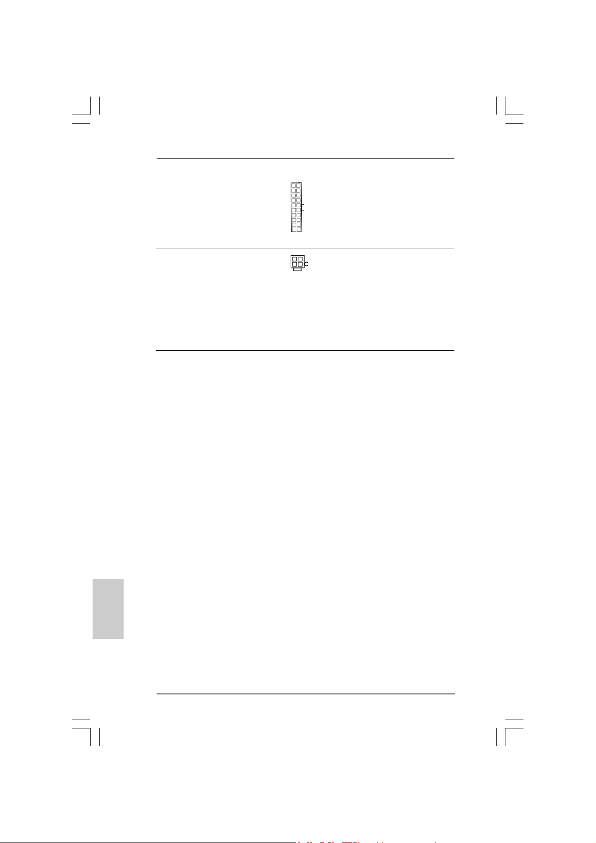
En-tête d’alimentation ATX Veuillez connecter l’unité
(ATXPW R1 br. 20) d’alimentation ATX sur cet en-
(voir p.2 No. 31) tête.
Connecteur d’alimentation Veuillez noter qu’il est nécessaire
12V ATX de connecter une unité
(ATX12V1 br . 4) d’alimentation électrique avec
(voir p.2 No. 7) prise ATX 12V sur ce connecteur
afin d’avoir une alimentation
suffisante. Faute de quoi, il ne
sera pas possible de mettre sous
tension.
2.62.6
Installation des Disques Durs Serial AInstallation des Disques Durs Serial A
2.6
Installation des Disques Durs Serial A
2.62.6
Installation des Disques Durs Serial AInstallation des Disques Durs Serial A
Cette carte mère utilise le chipset VIA VT8237 southbridge, qui prend en charge
les disques durs Série ATA (SATA). Vous pouvez installer des disques durs SATA
sur cette carte mère pour les périphériques de stockage internes. Cette section
vous guidera pour l’installation des disques durs SATA.
ETAPE 1 : Installez les disques durs SATA dans les baies pour disques de votre
châssis.
ETAPE 2 : Connectez le câble d’alimentation SATA au disque dur SATA.
ETAPE 3 : Connectez l’une des extrémités du câble de données SATA sur le
connecteur SATA de la carte mère.
ETAPE 4 : Connectez l’autre extrémité du câble de données SATA au disque dur
SATA.
TT
A (SAA (SA
T
A (SA
TT
A (SAA (SA
TT
A)A)
T
A)
TT
A)A)
Français
FrançaisFrançais
FrançaisFrançais
6060
60
6060
ASRock P4V88/P4V88+ Motherboard
Page 61

2.72.7
Fonction “Hot Plug” (“Connexion à chaud”) etFonction “Hot Plug” (“Connexion à chaud”) et
2.7
Fonction “Hot Plug” (“Connexion à chaud”) et
2.72.7
Fonction “Hot Plug” (“Connexion à chaud”) etFonction “Hot Plug” (“Connexion à chaud”) et
“Hot Swap” (“Remplacement à chaud”) pour les Disques“Hot Swap” (“Remplacement à chaud”) pour les Disques
“Hot Swap” (“Remplacement à chaud”) pour les Disques
“Hot Swap” (“Remplacement à chaud”) pour les Disques“Hot Swap” (“Remplacement à chaud”) pour les Disques
Durs SADurs SA
Durs SA
Durs SADurs SA
La Carte Mère P4V88/P4V88+ supporte la fonction “Hot Plug” pour les périphériques
SATA.
2.82.8
Installation de Windows 2000 / Windows XP avecInstallation de Windows 2000 / Windows XP avec
2.8
Installation de Windows 2000 / Windows XP avec
2.82.8
Installation de Windows 2000 / Windows XP avecInstallation de Windows 2000 / Windows XP avec
fonctions RAIDfonctions RAID
fonctions RAID
fonctions RAIDfonctions RAID
Si vous voulez installer le système d’exploitation Windows 2000 / Windows
XP sur vos disques durs SATA avec fonctions RAID, veuillez suivre la
procédure ci-dessous.
ETAPE 1 : Créez une disquette pilotes SATA.
TT
AA
T
A
TT
AA
REMARQUE
Qu’est-ce que la fonction « Hot Plug »?
Si les disques durs SATA ne sont pas en configuration RAID, l’action
d’insérer et de retirer des disques SATA alors que le système est sous
tension et en fonctionnement s’appelle le “Hot Plug”.
Qu’est-ce que la fonction « Hot Swap » ?
Si les disques durs sont montés en configuration RAID1 l’action d’insérer
et de retirer des disques SATA alors que le système est sous tension et
en fonctionnement s’appelle le “Hot Swap” .
A. Insérez le CD de soutien ASRock dans votre lecteur de disque optique
pour démarrer votre système. (N’insérez AUCUNE disquette dans le
lecteur de disquette pour l’instant!)
B. Pendant le POST au début du démarrage du système, appuyez sur la
touche <F11>, et une fenêtre s’affiche pour la sélection des
périphériques de démarrage. Veuillez sélectionner le CD-ROM comme
périphérique de démarrage.
C. Lorsque vous voyez s’afficher sur l’écran le message ”Do you want to
generate Serial ATA driver diskette [Y/N]?” (Voulez-vous générer une
disquette de pilotage Série ATA [Y/N]?), appuyez sur <Y>.
D. Vous voyez alors s’afficher les messages
Please insert a diskette into the floppy drive.,
WARNING! Formatting the floppy diskette will
lose ALL data in it!
Start to format and copy files [Y/N]?
ASRock P4V88/P4V88+ Motherboard
6161
61
6161
çaisçais
çaisçais
çais
FranFran
FranFran
Fran
Page 62

(Insérez une disquette dans le lecteur de disquette.
ATTENTION ! Le formatage de la dis quette provoquera
la perte de toutes les données qui s’y trouvent !
Commencer à formater et à copier les fichiers [Y/N].)
Veuillez insérez une disquette dans le lecteur de disquette, et
appuyer sur <Y>.
E. Le système commencera à formater la disquette et copiera les
données des disques durs SATA vers la disquette.
ETAPE 2 : Utilisez “SATA RAID BIOS ” pour définir la configuration
RAID.
Avant de commencer à configurer la fonction RAID, vous devez
consulter le guide d’installation sur le CD d’assistance pour connaître
la configuration correcte. Veuillez vous reporter à la documentation
qui se trouve sur le CD d’assistance, “Guide d’installation des
disques durs SATA et de configuration RAID, ” qui se trouve dans le
dossier sur le chemin suivant : .. \ SATA RAID BIOS
ETAPE 3 : Installer le système d’exploitation Windows 2000 /
Windows XP sur votre système.
Après avoir créé une disquette de pilotage SATA et utilisé “SATA
RAID BIOS” pour définir la configuration RAID, vous pouvez
commencer à installer Windows 2000 / Windows XP sur votre
système.
Après l’installation du système d’exploitation Windows 2000 / Windows XP, si
vous voulez gérer les fonctions RAID, vous pouvez utiliser à la fois “SATA RAID
BIOS” et “VIA RAID Tool” pour la configuration RAID. Veuillez vous reporter à la
documentation qui se trouve sur le CD d’assistance, “Guide d’installation des
disques durs SATA et de configuration RAID, ” qui se trouve dans le dossier sur le
chemin suivant : .. \ SATA RAID BIOS et le document sur le CD d’assistance,
“Guide de l’Utilitaire VIA RAID pour Windows,” qui se trouve dans le dossier sur le
chemin suivant : .. \ VIA RAID Tool
Français
FrançaisFrançais
FrançaisFrançais
6262
62
6262
1. Windows 98 / Windows ME ne prennent pas en charge les fonctions RAID.
2. Si vous voulez utiliser “VIA RAID Tool” dans un environnement Windows,
veuillez réinstaller les pilotes SATA à partir du CD d’assistance afin que “VIA
RAID Tool” soit aussi installé dans votre système.
ASRock P4V88/P4V88+ Motherboard
Page 63

2.92.9
Installation de Windows 98 / ME / 2000 / XP sansInstallation de Windows 98 / ME / 2000 / XP sans
2.9
Installation de Windows 98 / ME / 2000 / XP sans
2.92.9
Installation de Windows 98 / ME / 2000 / XP sansInstallation de Windows 98 / ME / 2000 / XP sans
fonctions RAIDfonctions RAID
fonctions RAID
fonctions RAIDfonctions RAID
Si vous voulez installer Windows 98 / ME / 2000 / XP sur vos disques durs SATA
sans les fonctions RAID ou si vous voulez installer Windows 98 / ME / 2000 / XP
bits sur vos disques durs IDE au lieu de disques durs SATA, veuillez vous
reporter aux méthodes ci-dessous pour l’installation correcte en fonction des
différentes versions du système d’exploitation Windows.
2.9.12.9.1
2.9.1
2.9.12.9.1
Si vous voulez installer Windows 98 / ME sur vos disques durs SATA sans
les fonctions RAID ou si vous voulez installer Windows 98 / ME sur vos
disques durs IDE au lieu de disques durs SATA, veuillez suivre la
procédure ci-dessous.
ETAPE 1 : Installez le système d’exploitation Windows 98 / ME sur
2.9.2 Installation de Windows 2000 / XP sans2.9.2 Installation de Windows 2000 / XP sans
2.9.2 Installation de Windows 2000 / XP sans
2.9.2 Installation de Windows 2000 / XP sans2.9.2 Installation de Windows 2000 / XP sans
Si vous voulez installer Windows 2000 / XP sur vos disques durs SATA
sans les fonctions RAID ou si vous voulez installer Windows 2000 / XP sur
vos disques durs IDE au lieu de disques durs SATA, veuillez suivre la
procédure ci-dessous.
ETAPE 1 : Configurez le BIOS.
ETAPE 2 : Installez le système d’exploitation Windows 2000 / XP
Installation de Windows 98 / ME sans fonctionsInstallation de Windows 98 / ME sans fonctions
Installation de Windows 98 / ME sans fonctions
Installation de Windows 98 / ME sans fonctionsInstallation de Windows 98 / ME sans fonctions
RAIDRAID
RAID
RAIDRAID
votre système.
Vous pouvez commencer à installer Windows 98 / ME sur votre
système.
fonctions RAID fonctions RAID
fonctions RAID
fonctions RAID fonctions RAID
A. Accédez à BIOS SETUP UTILITY (Utilitaire de configuration BIOS)
écran Avancé Configuration IDE.
B. Réglez l’option “Mode d’opération SATA” de [RAID] à [non-RAID].
sur votre système.
Après avoir configuré le BIOS, vous pouvez commencer à installer
Windows 2000 / XP sur votre système.
Si vous ne voulez pas configurer les fonctions RAID, il n’est pas nécessaire de
créer une disquette de pilotage SATA.
ASRock P4V88/P4V88+ Motherboard
6363
63
6363
çaisçais
çaisçais
çais
FranFran
FranFran
Fran
Page 64

3. Informations sur le BIOS3. Informations sur le BIOS
3. Informations sur le BIOS
3. Informations sur le BIOS3. Informations sur le BIOS
La puce Flash Memory sur la carte mère stocke le Setup du BIOS. Lorsque vous
démarrez l’ordinateur, veuillez presser <F2> pendant le POST (Power-On-SelfTest) pour entrer dans le BIOS; sinon, le POST continue ses tests de routine. Si
vous désirez entrer dans le BIOS après le POST, veuillez redémarrer le système
en pressant <Ctl> + <Alt> + <Suppr>, ou en pressant le bouton de reset sur le
boîtier du système.
Vous pouvez également redémarrer en éteignant le système et en le rallumant.
L’utilitaire d’installation du BIOS est conçu pour être convivial. C’est un programme
piloté par menu, qui vous permet de faire défiler par ses divers sous-menus et de
choisir parmi les choix prédéterminés. Pour des informations détaillées sur le
BIOS, veuillez consulter le Guide de l’utilisateur (fichier PDF) dans le CD technique.
Français
FrançaisFrançais
FrançaisFrançais
4. Informations sur le CD de suppor4. Informations sur le CD de suppor
4. Informations sur le CD de suppor
4. Informations sur le CD de suppor4. Informations sur le CD de suppor
Cette carte mère supporte divers systèmes d’exploitation Microsoft Windows:
98 SE / ME / 2000 / XP. Le CD technique livré avec cette carte mère contient les
pilotes et les utilitaires nécessaires pour améliorer les fonctions de la carte mère.
Pour utiliser le CD technique, insérez-le dans le lecteur de CD-ROM. Le Menu
principal s’affiche automatiquement si “AUTORUN” est activé dans votre
ordinateur. Si le Menu principal n’apparaît pas automatiquement, localisez dans le
CD technique le fichier “ASSETUP.EXE” dans le dossier BIN et double-cliquez
dessus pour afficher les menus.
tt
t
tt
6464
64
6464
ASRock P4V88/P4V88+ Motherboard
Page 65

1. Introduzione1. Introduzione
1. Introduzione
1. Introduzione1. Introduzione
Grazie per aver scelto una scheda madre ASRock P4V88/P4V88+, una scheda
madre affidabile prodotta secondo i severi criteri di qualità ASRock. Le prestazioni
eccellenti e il design robusto si conformano all’impegno di ASRock nella ricerca della
qualità e della resistenza.
Questa Guida Rapida all’Installazione contiene l’introduzione alla motherboard e la
guida passo-passo all’installazione. Informazioni più dettagliate sulla motherboard si
possono trovare nel manuale per l’utente presente nel CD di supporto.
Le specifiche della scheda madre e il software del BIOS possono
essere aggiornati, pertanto il contenuto di questo manuale può subire
variazioni senza preavviso. Nel caso in cui questo manuale sia
modificato, la versione aggiornata sarà disponibile sul sito di ASRock
senza altro avviso. Potete trovare la lista aggiornata delle memorie e
dei processori supportati anche sul sito di ASRock.
ASRock website http://www.asrock.com
1.1 Contenuto della confezione1.1 Contenuto della confezione
1.1 Contenuto della confezione
1.1 Contenuto della confezione1.1 Contenuto della confezione
Scheda madre ASRock P4V88/P4V88+
(ATX Form Factor: 12.0-in x 8.6-in, 30.5 cm x 21.8 cm)
Guida di installazione rapida ASRock P4V88/P4V88+
CD di supporto ASRock P4V88/P4V88+
Un cavo IDE 80-pin Ultra AT A 66/100/133
Un cavo per floppy drive a 1,44 Mb
Un cavo dati Serial ATA (SATA)
Un cavo alimentatore HDD Serial ATA (SATA) (Opzionale)
Un ASRock I/O Plus
TM
Shield
ASRock P4V88/P4V88+ Motherboard
6565
65
6565
ItalianoItaliano
ItalianoItaliano
Italiano
Page 66

Italiano
ItalianoItaliano
ItalianoItaliano
1.2 Specifiche1.2 Specifiche
1.2 Specifiche
1.2 Specifiche1.2 Specifiche
Piattaforma: ATX Form Factor: 12.0-in x 8.6-in, 30.5 cm x 21.8 cm
Processore: Socket 478 per Intel® Pentium® 4 (Prescott, Northwood, Willimate)/
Celeron® processore
Chipset: North Bridge:
VIA PT880, FSB @ 800/533/400 MHz,
supporta tecnologia Hyper-Threading
(vedi A TTENZIONE 1)
South Bridge:
VIA VT8237, supporta USB 2.0, ATA 133, SATA 1.5Gb/s
Memoria: 4 slot DDR DIMM: DDR1, DDR2, DDR3, e DDR4
2 Slot DIMM DDR Slots
Supporto PC3200 (DDR400), Max. 2GB,
4 Slot DIMM DDR Slots Supporto
PC2700 (DDR333) / PC2100 (DDR266), Max. 3.5GB
Supporto tecnologia Dual Channel Memory
(vedi A TTENZIONE 2)
IDE: IDE1: ATA133 / Ultra DMA Mode 6;
IDE2: ATA133 / Ultra DMA Mode 6;
Supporta fino a 4 dispositivi IDE
Serial ATA: 2 connettori SATA, supporta velocità di trasferimento dati fino
a 1.5Gb/s
Porta Floppy: Supporta fino a 2 floppy disk drive
Audio: AC’97 Audio a 5.1 canali;
LAN: Velocità: 802.3u (10/100 Ethernet), supporta Wake-On-LAN
Monitoraggio Hardware:
Sensore per la temperatura del processore,
Sensore per la temperatura dello Chassis,
Chiusura automatica del processore in caso di surriscaldamento
per proteggere la CPU (ASRock U-COP)(vedi ATTENZIONE 3),
Indicatore di velocità per la ventola del processore,
Indicatore di velocità per la ventola di raffreddamento,
Voltaggio: +12V, +5V, +3V, Vcore
Slot PCI: 5 slot con PCI Spec 2.2
Slot AGP: 1 slot AGP, supporta scheda AGP a 1.5V, modelli 8X / 4X
(vedi A TTENZIONE 4)
USB 2.0: 8 porte USB 2.0 :
comprende 6 porte USB 2.0 pronte all’uso nel pannello
posteriore, oltre ad una sulla scheda che supporta altre 2
porte USB 2.0 aggiuntive (vedi ATTENZIONE 5)
6666
66
6666
ASRock P4V88/P4V88+ Motherboard
Page 67

ASRock I/O PlusTM:
1 porta PS/2 per mouse, 1 porta PS/2 per tastiera,
1 Porta seriale: COM 1,
1 Porta parallela: supporto ECP/EPP,
6 porte USB 2.0 già integrate,
1 porta RJ 45,
Audio Jack: Line In / Line Out / Microfono
BIOS: Supporta AMI legal BIOS, Supporta “Plug and Play”,
Compatibile con ACPI 1.1 wake up events,
Supporta jumperfree, Supporta SMBIOS 2.3.1
Stepless control per frequenza del processore (solo per utenti
esperti, vedi A TTENZIONE 6)
Compatibilità SO: Microsoft® Windows® 98SE /ME / 2000 / XP
ATTENZIONE!
1. Per il settaggio della “Tecnologia Hyper-Threading”, per favore
controllare pagina 25 del Manuale dell’utente all’interno del CD di
supporto.
2. Questa scheda madre supporta la tecnologia Dual Channel Memory.
Prima di implementare la tecnologia Dual Channel Memory, assicurarsi
di leggere la guida all’installazione dei moduli di memoria, a pagina 69,
per seguire un’installazione appropri ata.
3. Se il processore si surriscalda, il sistema si chiude automaticamente.
Prima di riavviare il sistema, assicurarsi che la ventolina CPU della
scheda madre funzioni correttamente; scollegare e ricollegare il cavo
d’alimentazione. Per migliorare la dissipazione del calore, ricordare di
applicare l’apposita pasta siliconica tra il processore e il dissipatore quando
si installa il sistema.
4. NON usare schede AGP da 3,3 V nello slot AGP di questa motherboard!
Ciò potrebbe provocare danni permanenti!
5. La Gestione Risorse per USB 2.0 funziona perfettamente con Microsoft
Windows® XP SP1/2000 SP4. Potrebbe dare qualche problema con
Microsoft® Windows® 98/ME.
6. Anche se questa motherboard offre il controllo stepless, non si consiglia
di effettuare l’overclocking. Frequenze del bus del processore diverse
da quelle raccomandate possono causare instabilità al sistema o danni
al processore e alla scheda madre.
®
ASRock P4V88/P4V88+ Motherboard
6767
67
6767
ItalianoItaliano
ItalianoItaliano
Italiano
Page 68

2. Installazione2. Installazione
2. Installazione
2. Installazione2. Installazione
Precauzioni preinstallazionePrecauzioni preinstallazione
Precauzioni preinstallazione
Precauzioni preinstallazionePrecauzioni preinstallazione
Leggere le seguenti precauzioni prima di installare componenti delle schede madri o
di cambiare le impostazioni delle schede madri.
1. Togliere il cavo dalla presa elettrica prima di toccare le componenti. In caso
contrario la schedamadre, le periferiche, e/o i componenti possono subire
gravi danni.
2. Per evitare che l’elettricità statica danneggi la scheda madre, NON appoggiare
la scheda madre su moquette, tappeti o tessuti simili. Ricordarsi di indossare
un braccialetto antistatico collegato a terra o di toccare un oggetto posizionato
a terra prima di maneggiare le componenti.
3. Tenere i componenti per i bordi e non toccare i ICs.
4. Ogni volta che si disinstalla un componente, appoggiarlo su un tappetino
antistatico messo a terra o depositarlo nella borsa data in dotazione con il
componente.
2.1 Installazione del processore2.1 Installazione del processore
2.1 Installazione del processore
2.1 Installazione del processore2.1 Installazione del processore
Step 1. Aprire lo zoccolo sollevando la leva da un angolo di 90°.
Step 2. Posizionare il processore direttamente sullo zoccolo cos da far
combaciare gli angoli segnati con la leva del connettore.
Step 3. Inserire con cautela il processore nello zoccolo finché si adatta
perfettamente.
Italiano
ItalianoItaliano
ItalianoItaliano
6868
68
6868
Il processore ha un solo corretto orientamento. NON forzare il
processore nello zoccolo: i pin potrebbero stortarsi.
Step 4. Quando il processore è posizionato, premere con decisione sullo
zoccolo mentre si abbassa la leva dello zonnettore per fissare il
processore. Quando la leva fa clic sulla linguetta laterale significa che è
bloccata.
Step 5. Installare la ventola del processore e l’heatsink. Per una corretta
installazione, per favore fare riferimento ai manuali di istruzione dei
produttori della ventola e dell’heatsink del processore.
ASRock P4V88/P4V88+ Motherboard
Page 69

2.2 Installazione dei moduli di memoria (DIMM)2.2 Installazione dei moduli di memoria (DIMM)
2.2 Installazione dei moduli di memoria (DIMM)
2.2 Installazione dei moduli di memoria (DIMM)2.2 Installazione dei moduli di memoria (DIMM)
La scheda madre P4V88/P4V88+ fornisce quattro alloggiamenti DIMM DDR (Double
Data Rate) a 184 pin, e supporta la tecnologia Dual Channel Memory. Per la
configurazione a due canali, è necessario installare sempre coppie identiche
(stessa marca, velocità, dimensioni e tipo di chi p) di DIMM DDR negli alloggi amenti
dello stesso colore. In altre parole, è necessario installare coppie identiche di DIMM
DDR nel canale doppio A (DDR1 e DDR3; alloggiamenti blu; vedere pag. 2 Nr. 6)
oppure coppie identiche di DIMM DDR nel canale doppio B (DDR2 e DDR4;
alloggiamenti neri; vedere pag. 2 Nr. 10), per fare sì che la tecnologia Dual Channel
Memory possa essere attivata. Questa scheda madre consente anche di
installare quattro DIMM DDR per la configurazione a canale doppio.Questa scheda
madre consente anche di installare quattro DIMM DDR per configurazione a canale
duale, si raccoma nda di installare DIMM DD R identiche nei quattro alloggi amenti.
Consultare la Tabella configurazione Memoria Canale Duale di seguito.
Configurazioni Dual Channel Memory
DDR1 DDR2 DDR3 DDR4
(alloggia mento blu) (alloggia mento nero) (alloggiamento blu) (alloggiamento nero)
(1) Popolato - Popolato (2) - Popolato - Popolato
(3) Popolato Popolato Popolato Popolato
1. Se si vogliono installare due moduli di memoria, per ottenere
compatibilità ed affidabilità ottimali, si raccomanda di installarli negli
alloggia menti dello stesso colore. In altre parole: in stallare i moduli di
memoria o nella serie di alloggiamenti blu (DDR1 e DDR3) oppure
nella serie di alloggiamenti nera (DDR2 e DDR4).
2. Se negli alloggiamenti DIMM di questa scheda madre è installato un
solo modulo di memoria, oppure sono installati tre moduli di memoria,
è impossibile attivare la tecnologia Dual Channel Memory.
3. Se una coppia di moduli di memoria NON è installata nello stesso
“canale doppio”, ad esempio se si installa una coppia di moduli di
memoria su DDR1 e DD2, è impossibile attivare la tecnologia
Dual Channel Memory.
ASRock P4V88/P4V88+ Motherboard
6969
69
6969
ItalianoItaliano
ItalianoItaliano
Italiano
Page 70

Installare una DIMMInstallare una DIMM
Installare una DIMM
Installare una DIMMInstallare una DIMM
Scollegare l’alimentazione elettrica prima di aggiungere o rimuovere i
DIMM o altri componenti del sistema.
Step 1. Sbloccare lo slot DIMM premendo i fermi che lo trattengono verso
l’esterno.
Step 2. Allineare una DIMM sullo slot così che il pettine della DIMM comba ci con
la sua sede sullo slot.
La DIMM può essere montata correttamente soltanto con un
orientamento. Se si dovesse installare a forza la DIMM nello slot con
un orientamento errato, si causerebbero danni permanenti alla scheda
madre e alla DIMM stessa.
Italiano
ItalianoItaliano
ItalianoItaliano
7070
70
7070
Step 3. Inserire saldamente la DIMM nello slot fino a far scattare completamente
in posizione i fermagli di ritegno alle due estremità e fino ad installare
correttamente la DIMM nella sua sede.
ASRock P4V88/P4V88+ Motherboard
Page 71

2.3 Slot di espansione (PCI e slot AGP)2.3 Slot di espansione (PCI e slot AGP)
2.3 Slot di espansione (PCI e slot AGP)
2.3 Slot di espansione (PCI e slot AGP)2.3 Slot di espansione (PCI e slot AGP)
Esistono 5 slot PCI e 1 slot AGI su entrambe le schede madri P4V88/P4V88+.
Slot PCI: Sono utilizzati per installare schede di espansione con Interfaccia PCI
a 32-bit.
Slot AGP: Lo slot AGP serve all’installazione di schede grafiche. Lo slot AGP
ASRock usa uno speciale gancio che permette di fissare in sede in
modo sicuro la scheda grafica.
NON usare schede AGP da 3,3 V nello slot AGP di questa
motherboard! Ciò potrebbe provocare danni permanenti! Per le
informazioni relative alla tensione della scheda AGP, si prega di
contattare il fornitore della scheda AGP.
Installare una scheda di espansioneInstallare una scheda di espansione
Installare una scheda di espansione
Installare una scheda di espansioneInstallare una scheda di espansione
Step 1. Prima d’installare la scheda di espansione, assicurarsi che l’alimentazione
sia stata esclusa oppure che il cavo di alimentazione sia scollegato. Prima
di iniziare l’installazione, si prega di leggere la documentazione della scheda
di espansione e di effettuare le necessarie impostazioni del hardware.
Step 2. Rimuovere i ganci sullo slot che si intende utilizzare. Tenere a portata di
mano le viti.
Step 3. Allineare il connettore della scheda con lo slot e premere con decisione
finché la scheda è completamente inserita nello slot.
Step 4. Agganciare la scheda allo chassis con le viti.
ASRock P4V88/P4V88+ Motherboard
7171
71
7171
ItalianoItaliano
ItalianoItaliano
Italiano
Page 72

2.4 Setup dei Jumpers2.4 Setup dei Jumpers
2.4 Setup dei Jumpers
2.4 Setup dei Jumpers2.4 Setup dei Jumpers
L’illustrazione mostra come sono settati i jumper.
Quando il ponticello è posizionato sui pin, il jumper
è “CORTOCIRCUITATO”. Se sui pin non ci sono
ponticelli, il jumper è “APERTO”. L’illustrazione
mostra un jumper a 3 pin in cui il pin1 e il pin2
sono “CORTOCIRCUIT ATI” quando il ponticello è
posizionato su questi pin.
Jumper Settaggio del Jumper Descrizione
PS2_USB_PWR1 Cortocircuitare pin2, pin3 per
(vedi p.2 Nr. 1) settare a +5VSB (standby) e
Nota: Per selezionare +5VSB, si richiedono almeno 2 Ampere e il consumo di
corrente in standby sarà maggiore.
JR1(vedi p.2 Nr. 26)
JL1(vedi p.2 Nr. 25)
Nota: Se i jumper JL1 e JR1 sono chiusi, funzionano sia i connettori audio frontali
che posteriori.
Resettare la CMOS
(CLRCMOS1, jumper a 2 pin)
(vedi p.2 Nr. 15)
jumper a 2 pin
CORTOCIRCUIT ATO APERT O
abilitare PS/2 o USB wake up
events.
Italiano
ItalianoItaliano
ItalianoItaliano
7272
72
7272
Nota: CLRCMOS1 consente di pulire i dati nella CMOS. I dati nella CMOS includono
informazioni del setup del sistema, come per esempio la password di
sistema, la data, l’ora, e i parametri del setup di sistema. Per pulire I parametri
di sistema e resettare ai parametri di default, spegnere il computer e
scollegare l’alimentatore, poi collegare il jumper sul CLRCMOS1 per 3
secondi. Per favore ricordarsi di rimuovere il jumper cap dopo la pulizia della
CMOS. Per favore ricordarsi di rimuovere il jumper cap dopo la pulizia della
CMOS. Se si deve cancellare il CMOS non appena terminato l’aggiornamento
del BIOS, prima di eseguire tale operazione di cancellazione è necessario
riavviare innanzitutto il sistema, e quindi spegnerlo.
ASRock P4V88/P4V88+ Motherboard
Page 73

2.5 Collettori e Connettori su Scheda2.5 Collettori e Connettori su Scheda
2.5 Collettori e Connettori su Scheda
2.5 Collettori e Connettori su Scheda2.5 Collettori e Connettori su Scheda
I collettori ed i connettori su scheda NON sono dei jumper. NON installare
cappucci per jumper su questi collettori e connettori. L’installazione di
cappucci per jumper su questi collettori e connettori provocherà danni
permanenti alla scheda madre!
Connettore del
Floppy disk
(33-pin FLOPPY1)
(vedi p.2 Nr. 16)
Lato del Pin1 con la striscia rossa
Nota: Assicurarsi che il lato del cavo con la striscia rossa sia inserito nel lato Pin1
del connettore.
Connettore IDE primario (blu) Connettore IDE secondario (nero)
(39-pin IDE1, vedi p.2 Nr. 9) (39-pin IDE2, vedi p.2 Nr. 8)
Connettore blu Connettore nero
alla schedamadre all’hard disk drive
Cavo ATA 66/100/133 a 80 pin
Nota: Se utilizzate un solo dispositivo IDE su questa scheda madre, imposta tale
dispositivo come “Master”. Fate riferimento alle istruzioni del produttore del
dispositivo IDE per maggiori dettagli. Inoltre, per ottimizzare compatibilità e
prestazioni, connettete l’hard disk al connettore primario IDE (IDE1, blu) e il
CD-ROM al connettore IDE secondario (IDE2, nero).
Connettori Serial ATA Questi due connettori Serial ATA
(SAT A1: vedi p.2 Nr . 13) (SATA) supportano cavi dati
(SAT A2: vedi p.2 Nr . 12) SATA per dispositivi di
SAT A2
SAT A1
immagazzina mento interni.
ATA (SATA) supportano cavi
SATA per dispositivi di memoria
interni. L’interfaccia SATA
attuale permette velocità di
trasferimento dati fino a 1.5 Gb/s.
ASRock P4V88/P4V88+ Motherboard
7373
73
7373
ItalianoItaliano
ItalianoItaliano
Italiano
Page 74

Cavi dati Serial ATA (SATA) Entrambe le estremità del cavo
dati SATA possono collegarsi
all’hard disk SATA o al
connettore SATA sulla scheda
madre.
Cavo d’alimentazione Collegare l’estremità nera de
Serial A TA (SA TA) cavo di alimentazione SATA al
(Opzionale) connettore di alimentazione del
Connettere all’ailmentazione
dei dischi SAT A
Connettere al gruppo
di alimentazione
drive. Poi connettete l’estremità
bianca del cavo di alimentazione
SATA al connettore power
dell’alimentatore.
USB 2.0 Header ASRock I/O PlusTM è fornita di 6
(9-pin USB67) porte USB 2.0 già integrate sul
(vedi p.2 Nr. 20) pannello posteriore. Se le porte
USB sul pannello posteriore non
sono sufficienti, questo USB 2.0
Header (USB67) fornisce 2
porte USB 2.0 aggiuntive.
Collettore USB 2.0 Questo collettore USB4_5 è
condiviso condiviso con le porte USB 2.0
(9-pin USB4_5) 4 e 5 su ASRock I/O Plus™.
(vedi p.2 Nr. 30) Quando si utilizzano le porte
USB del pannello frontale,
attaccando il cavo USB
pannello frontale a questo
collettore (USB4_5), le porte 4
e 5 su ASRock I/O Plus™ non
saranno in grado di funzionare.
Italiano
ItalianoItaliano
ItalianoItaliano
7474
74
7474
Connettore modulo Questo connettore supporta
infrarossi una wireless opzionale che
(5-pin IR1) trasmette e riceve moduli
(vedi p.2 Nr. 21) infrarossi.
ASRock P4V88/P4V88+ Motherboard
Page 75

Connettori audio interni Permettono di ricevere input
(4-pin CD1, 4-pin AUX1) stereo audio da fonti di suono
(CD1: vedi p.2 Nr. 29) come CD-ROM, D V D-ROM,TV
(AUx1: vedi p.2 Nr. 28) tuner, o schede MPEG.
CD1
AUX1
Connettore audio sul pannello È un’interfaccia per il cavo del
frontale pannello audio. Che consente
(9-pin AUDIO1) connessione facile e controllo
(vedi p.2 Nr. 27) dei dispositivi audio.
Connettore del panello Questo connettore accoglie
frontale diverse funzioni del pannello
(9-pin PANEL1) frontale.
(vedi p.2 Nr. 17)
Collettore casse telaio Collegare le casse del telaio a
(4-pin SPEAKER1) questo collettore.
(vedi p.2 Nr. 18)
Connettore ventolina telaio Collegare il cavo della ventolina
(3-pin CHA_FAN1) telaio a questo connettore e far
(vedi p.2 Nr. 19) combaciare il filo nero al pin
terra.
Connettore ventolina CPU Collegare il cavo della ventolina
(3-pin CPU_FAN1) CPU a questo connettore e far
(vedi p.2 Nr. 2) combaciare il filo nero al pin
terra.
Connettore porta giochi Connettere un cavo Game a
(15-pin GAME1) questo connettore solo se la
(vedi p.2 Nr. 22) porta giochi è installata.
ASRock P4V88/P4V88+ Motherboard
7575
75
7575
ItalianoItaliano
ItalianoItaliano
Italiano
Page 76
Collettore alimentazione ATX Collegare la sorgente
(20-pin ATXPW R1) d’alimentazione ATX a questo
(vedi p.2 Nr. 31) collettore.
Connettore ATX 12V È necessario collegare una
(4-pin ATX12V1) alimentazione con spinotto da
(vedi p.2 Nr. 7) 12V ATX a questo connettore
in modo che possa fornire
energia sufficiente. In caso
contrario l’unità non si avvia.
Italiano
ItalianoItaliano
ItalianoItaliano
7676
76
7676
ASRock P4V88/P4V88+ Motherboard
Page 77

2.62.6
Installazione di Hard Disk AInstallazione di Hard Disk A
2.6
Installazione di Hard Disk A
2.62.6
Installazione di Hard Disk AInstallazione di Hard Disk A
Questa scheda madre adotta il chipset southbridge VIA VT8237 che supporta
hard disk Serial ATA (SATA). Potete installare hard disk SATA su questa scheda
madre per dispositivi di immagazzinamento interni. Questa sezione illustra come
installare hard disk SATA.
1° PASSO: Installare gli Hard Disk SATA negli spazi per le unità disco del telaio.
2° PASSO: Collegare il cavo d’alimentazione SATA al disco rigido SATA.
3° PASSO: Collegare un’estremità del cavo dati SATA al connettore SATA della
motherboard.
4° PASSO: Collegare l’altra estremità del cavo dati SATA all’hard disk SATA.
2.72.7
Funzione di collegamento e scambio a caldo per iFunzione di collegamento e scambio a caldo per i
2.7
Funzione di collegamento e scambio a caldo per i
2.72.7
Funzione di collegamento e scambio a caldo per iFunzione di collegamento e scambio a caldo per i
dischi rigidi SAdischi rigidi SA
dischi rigidi SA
dischi rigidi SAdischi rigidi SA
La scheda madre P4V88/P4V88+ supporta la funzione di collegamento e scambio
a caldo per i dispositivi SATA.
NOTA
Che cosa è la funzione di collegamento a caldo?
Se i dischi rigidi SATA NON sono impostati per una configurazione
RAID, è detta “collegamento a caldo” l’azione d’inserimento e
rimozione dei dischi rigidi SATA mentre il sistema è ancora acceso ed
in condizione di funzionamento.
TT
AA
T
A
TT
AA
TT
A Seriali (SAA Seriali (SA
T
A Seriali (SA
TT
A Seriali (SAA Seriali (SA
TT
A)A)
T
A)
TT
A)A)
Che cosa è la funzione di scambio a caldo?
Se i dischi rigidi SATA sono impostati in una configurazione RAID1
allora è detta “scambio a caldo” l’azione d’inseri mento e rimozione dei
dischi rigidi SATA mentre il sistema è ancora acceso ed in condizione
di funzionamento.
2.82.8
Installazione di Windows 2000 / Windows XP conInstallazione di Windows 2000 / Windows XP con
2.8
Installazione di Windows 2000 / Windows XP con
2.82.8
Installazione di Windows 2000 / Windows XP conInstallazione di Windows 2000 / Windows XP con
funzioni RAIDfunzioni RAID
funzioni RAID
funzioni RAIDfunzioni RAID
Se si desidera installare il sistema operativo Windows 2000 / Windows XP
sull’unità disco rigido SATA HDDs con funzioni RAID, seguire le istruzioni
esposte di seguito.
Passo 1: Creare un dischetto driver SATA.
A. Inserire il CD di supporto ASRock nel lettore ottico prima di
accendere il sistema. (NON inserire nessun dischetto floppy nel
drive in questo momento!)
B. Durante la fase di POST, all’inzio del boot-up del sistema, premere il
tasto <F11>. Apparirà una finestra per la selezione dei dispositivi
ASRock P4V88/P4V88+ Motherboard
7777
77
7777
ItalianoItaliano
ItalianoItaliano
Italiano
Page 78

boot. Scegliere CD-ROM come dispositivo di boot. Durante la fase di
POST, all’inzio del boot-up del sistema, premere il tasto <F11>.
Apparirà una finestra per la selezione dei dispositivi boot. Scegliere
CD-ROM come dispositivo di boot .
C. Quando sullo schermo compare il messaggio: ”Do you want to
generate Serial ATA driver diskette [Y/N]?” (Vuoi creare un dischetto
di driver Serial ATA [Y/N]?), premere <Y>.
D. Di seguito ci sarà questo messaggio:
Please insert a diskette into the floppy drive.
WARNING! Formatting the floppy diskette will
lose ALL data in it!
Start to format and copy files [Y/N]?
(Inserire un dischetto nel floppy drive.
ATTENZIONE! La formattazione del dischetto floppy
comporterà la perdita di TUTTI i dati in esso contenuti!
Iniziare a formattare e copiare i file [Y/N]?)
Inserire un dischetto floppy nel floppy drive e premere <Y>.
E. Il sistema inizierà a formattare il floppy-disk e a copiare i driver SATA
su questo.
Passo 2: Usare “SATA RAID BIOS” per impostare la configurazione
RAID.
Prima di procedere alla configurazione della funzione RAID, è necessario
controllare la guida all’installazione contenuta nel CD di supporto per
eseguire correttamente l’operazione. Far riferimento al documento del CD
di supporto denominato “Guide to SATA Hard Disks Installation a nd RAID
Configuration - Guida all’installazione del disco rigido SATA e alla
configurazione RAID”, contenuto nella cartella con percorso: .. \ SATA
RAID BIOS
Passo 3: Installazione di Windows 2000 / Windows XP sul sistema.
Dopo aver creato un dischetto driver SATA e aver usato “SATA RAID
BIOS” per impostare la configurazione RAID, è possibile avviare
l’installazione di Windows 2000 / Windows XP sul sistema.
Italiano
ItalianoItaliano
ItalianoItaliano
7878
78
7878
Dopo l’installazione di Windows 2000 / Windows XP, per gestire funzioni
RAID, è possibile utilizzare sia “SATA RAID BIOS” sia “VIA RAID Tool” e
eseguire la configurazione RAID. Far riferimento al documento del CD di
supporto denominato “Guide to SATA Hard Disks Installation a nd RAID
Configuration -Guida all’installazione del disco rigido SATA e alla
configurazione RAID” contenuto nella cartella con percorso: .. \
SATA RAID BIOS e al documento del medesimo CD denominato “Guide to
VIA RAID Tool - Guida al VIA RAID Tool ” contenuto nella cartella con
percorso: .. \ VIA RAID Tool
ASRock P4V88/P4V88+ Motherboard
Page 79

1. Windows 98 e Windows ME non supportano le funzioni RAID.
2. Se si desidera utilizzare “VIA RAID Tool” in ambiente Windows, installare
nuovamente i driver SATA contenuti nel CD di supporto per eseguire anche
l’installazione di “VIA RAID Tool” sul sistema.
2.92.9
Installazione di Windows 98 / ME / 2000 / XP senzaInstallazione di Windows 98 / ME / 2000 / XP senza
2.9
Installazione di Windows 98 / ME / 2000 / XP senza
2.92.9
Installazione di Windows 98 / ME / 2000 / XP senzaInstallazione di Windows 98 / ME / 2000 / XP senza
funzioni RAIDfunzioni RAID
funzioni RAID
funzioni RAIDfunzioni RAID
Se si desidera installare Windows 98 / ME / 2000 / XP sulle unità disco rigido SATA
senza funzioni RAID o installare Windows 98 / ME / 2000 / XP sulle unità disco
rigido IDE e non sulle unità di SATA, far riferimento ai metodi illustrati di seguito, per
eseguire l’operazione nella maniera corretta in base alla diversa versione di
Windows di cui si è in possesso.
2.9.12.9.1
2.9.1
2.9.12.9.1
Se si desidera installare Windows 98 / ME sulle unità disco rigido SATA
senza funzioni RAID o installare Windows 98 / ME sulle unità disco rigido
IDE e non sulle unità di SATA, seguire le istruzioni esposte di seguito.
Passo 1: Installazione di Windows 98 / ME sul sistema.
2.9.22.9.2
2.9.2
2.9.22.9.2
Se si desidera installare Windows 2000 / XP sulle unità disco rigido SATA
senza funzioni RAID o installare Windows 2000 / XP sulle unità disco rigido
IDE e non sulle unità di SATA, seguire le istruzioni esposte di seguito.
Passo 1: Configurare il BIOS.
Passo 2: Installazione di Windows 2000 / XP sul sistema.
Installazione di Windows 98 / ME senza funzioniInstallazione di Windows 98 / ME senza funzioni
Installazione di Windows 98 / ME senza funzioni
Installazione di Windows 98 / ME senza funzioniInstallazione di Windows 98 / ME senza funzioni
RAIDRAID
RAID
RAIDRAID
è possibile procedere all’installazione di Windows 98 / ME sul
sistema.
Installazione di Windows 2000 / XP senzaInstallazione di Windows 2000 / XP senza
Installazione di Windows 2000 / XP senza
Installazione di Windows 2000 / XP senzaInstallazione di Windows 2000 / XP senza
funzioni RAIDfunzioni RAID
funzioni RAID
funzioni RAIDfunzioni RAID
A. Entrare in BIOS SETUP UTILITY (UTILITÀ DI CONFIGURAZIONE DEL
BIOS) Advanced screen (Avanzate) IDE Configuration
(Configurazione IDE).
B. Commutare l’opzione “SATA Operation Mode” (Modalità di
funzionamento SATA) da [RAID] a [non-RAID].
Dopo la configurazione del BIOS, è possibile procedere
all’installazione di Windows 2000 / XP sul sistema.
Se non si desidera installare le funzioni RAID, non è necessario creare un
dischetto driver SATA.
ItalianoItaliano
ItalianoItaliano
Italiano
ASRock P4V88/P4V88+ Motherboard
7979
79
7979
Page 80

3. Informazioni sul BIOS3. Informazioni sul BIOS
3. Informazioni sul BIOS
3. Informazioni sul BIOS3. Informazioni sul BIOS
La Flash Memory sulla scheda madre contiene le Setup Utility. Quando si avvia il
computer, premi <F2> durante il Power-On-Self-Test (POST) della Setup utility del
BIOS; altrimenti, POST continua con i suoi test di routine. Per entrare il BIOS Setup
dopo il POST, riavvia il sistema premendo <Ctl> + <Alt> + <Delete>, o premi il tasto
di reset sullo chassis del sistema. Per informazioni più dettagliate circa il Setup del
BIOS, fare riferimento al Manuale dell’Utente (PDF file) contenuto nel cd di
supporto.
Italiano
ItalianoItaliano
ItalianoItaliano
4. Software di suppor4. Software di suppor
4. Software di suppor
4. Software di suppor4. Software di suppor
su CD su CD
su CD
su CD su CD
Questa scheda madre supporta vari sistemi operativi Microsoft® Windows®: 98 SE /
ME / 2000 / XP. Il CD di supporto a corredo della scheda madre contiene i driver e
utilità necessari a potenziare le caratteristiche della scheda.
Inserire il CD di supporto nel lettore CD-ROM. Se la funzione “AUTORUN” è attivata nel
computer, apparirà automaticamente il Menù principale. Se il Menù principale non
appare automaticamente, posizionarsi sul file “ASSETUP.EXE” nel CESTINO del CD di
supporto e cliccare due volte per visualizzare i menù.
to e informazionito e informazioni
to e informazioni
to e informazionito e informazioni
8080
80
8080
ASRock P4V88/P4V88+ Motherboard
Page 81

1. Introducción1. Introducción
1. Introducción
1. Introducción1. Introducción
Gracia s por su compra de ASRock P4V88/P4V88+ placa madre, un a pla ca de confia nza
producida bajo el control de calidad estricto y persistente. La placa madre provee
realización excelente con un diseño robusto conforme al compromiso de calidad y
resistencia de ASRock.
Esta Guía rápida de instalación contiene una introducción a la placa base y una guía
de instalación paso a paso. Puede encontrar una información más detallada sobre la
placa base en el manual de usuario incluido en el CD de soporte.
Porque las especificaciones de la placa madre y el software de BIOS
podrían ser actualizados, el contenido de este manual puede ser cambiado
sin aviso. En caso de cualquier modificación de este manual, la versión
actualizada estará disponible en el website de ASRock sin previo aviso.
Puede encontrar también las listas más recientes de soporte de memoria y
CPU en el sitio web ASRock.
Website de ASRock http://www.asrock.com
1.1 Contenido de la caja1.1 Contenido de la caja
1.1 Contenido de la caja
1.1 Contenido de la caja1.1 Contenido de la caja
Placa base ASRock P4V88/P4V88+
(Factor forma ATX: 30,5 cm x 21.8 cm, 12,0” x 8,6”)
Guía de instalación rápida de ASRock P4V88/P4V88+
CD de soporte de ASRock P4V88/P4V88+
Una cinta de datos IDE de conducción 80 Ultra ATA 66/100/133
Una cinta de datos para una unidad de disco de 3,5”
Un Cable de Datos Serial A T A (SA T A)
Un cable serie ATA (SATA) de alimentación de disco duro (Opcional)
Una protección ASRock I/O Plus
TM
ASRock P4V88/P4V88+ Motherboard
8181
81
8181
EspañolEspañol
EspañolEspañol
Español
Page 82

Español
EspañolEspañol
EspañolEspañol
1.2 Especificación1.2 Especificación
1.2 Especificación
1.2 Especificación1.2 Especificación
Plataforma: Factor forma ATX: 30,5 cm x 21.8 cm, 12,0” x 8,6”
Procesador: Zócalo 478 para procesador Intel® Pentium® 4 (Prescott,
Northwood, Willimate) / Celeron
Chipset: North Bridge:
VIA PT880, FSB @ 800/533/400 MHz,
soporte a la tecnología Hyper-Threading (ver ATENCIÓN 1)
South Bridge:
VIA VT8237, soporta USB 2.0, ATA 133, SATA 1.5Gb/s
Memoria: 4 DDR DIMM slots: DDR1, DDR2, DDR3, y DDR4
2 ranura s DDR DIMM
con soporte para PC3200 (DDR400), Máx. 2 GB,
4 ranuras DDR DIMM con soporte para
PC2700 (DDR333) / PC2100 (DDR266), Máx. 3,5 GB
Soporte de Tecnología de Memoria de Doble Canal
(ver ATENCIÓN 2)
IDE: IDE1: ATA133/ Ultra DMA Mode 6
IDE2: ATA133/ Ultra DMA Mode 6
Admite hasta 4 dispositivos IDE
ATA serie: 2 conexiones SATA, admiten una velocidad de transferencia
de datos de hasta 1,5Gb/s
Puerto Floppy: Admite hasta 2 unidades de disco
Audio: AC’97 Audio, 5.1 canales
LAN: Velocidad: 802.3u (10/100 Ethernet), soporta Wake-On-LAN
Monitor Hardware:Sensor para la temperature del procesador,
Sensor para la temperatura del chasis,
Corte automático en caso de temperatura sobre-elevada de
CPU (ASRock U-COP)(ver ATENCIÓN 3),
Taquímetro del ventilador del CPU,•
Taquímetro del ventilador del chasis,
Monitor Voltaje: +12 V, + 5V, + 3V, Vcore
Slot PCI: 5 slot con PCI especificación 2.2
Slot AGP: 1 slot AGP, soporta tarjeta AGP de 1.5V, 8X / 4X
(ver ATENCIÓN 4)
USB 2.0: 8 puertos USB 2.0:
incluyen 6 puertos USB 2.0 listos para su uso en el panel
anterior, más un cabezal en la placa con soporte para 2
puertos USB 2.0 adicionales (ver ATENCIÓN 5)
®
8282
82
8282
ASRock P4V88/P4V88+ Motherboard
Page 83

ASRock I/O PlusTM: 1 puerto de ratón PS/2, 1 puerto de teclado PS/2,
1 puerto serial: COM 1,
1 puerto paralelo: soporta ECP/EPP,
6 puertos USB 2.0 predeterminados,
1 puerto RJ45,
Audio Jack: Line In / Line Out / Micrófono
BIOS: AMI legal BIOS, Soporta “Plug and Play”,
ACP1.1 compliance wake up events,
Soporta “jumper free setup”, Soporta SMBIOS 2.3.1,
Stepless control de frecuencia de CPU
(sólo para usuario avanzado, ver ATENCIÓN 6)
OS: En conformidad con Microsoft® Windows® 98SE / ME / 2000 / XP
AA
TENCIÓN!TENCIÓN!
A
TENCIÓN!
AA
TENCIÓN!TENCIÓN!
1. Por favor consulte página 25 del Manual del Usuario en el soporte CD
sobre la configuración de Hyper-Threading Technology.
2. Esta placa base soporta Tecnología de Memoria de Doble Canal. Antes de
implementar la Tecnología de Memoria de Doble Canal, asegúrese de leer
la guía de instalación de módulos de memoria en la página 85 para su
correcta instalación.
3. Cuando la temperatura de CPU está sobre-elevada, el sistema va a
apagarse automaticamente. Antes de reanudar el sistema, compruebe si
el ventilador de la CPU de la placa base funciona apropiadamente y
desconecte el cable de alimentación, a continuación, vuelva a conectarlo.
Para mejorar la disipación de calor, acuérdese de aplicar thermal grease
entre el procesador y el disipador de calor cuando usted instala el
sistema de PC.
4. NO utilice una tarjeta AGP de 3,3V AGP en la ranura AGP de esta placa
base. Podría causar daños permanentes.
5. Power Management para USB 2.0 funciona bien bajo Microsoft® Windows
XP SP1/2000 SP4. Es posible que no funcione propiamente bajo
Microsoft® Windows® 98/ME.
6. Aunque esta placa base ofrece un control complete, no es recomendable
forzar la velocidad. Las frecuencias de bus de la CPU distintas a las
recomendadas pueden causar inestabilidad en el sistema o dañar la CPU.
®
ASRock P4V88/P4V88+ Motherboard
8383
83
8383
EspañolEspañol
EspañolEspañol
Español
Page 84

2. Instalación2. Instalación
2. Instalación
2. Instalación2. Instalación
Precaución de Pre-instalaciónPrecaución de Pre-instalación
Precaución de Pre-instalación
Precaución de Pre-instalaciónPrecaución de Pre-instalación
Tenga en cuenta las precauciones siguientes antes de instalar los componentes
de la placa base o cambiar cualquier configuración de la placa base.
1. Desconecte el cable de electricidad antes de tocar cualquier componente.
2. Para prevenir daño del componente de la placa madre por electricidad estástica,
NUNCA ponga su placa madre directamente sobre la alfombra y otros por el
estilo. Póngase la pulsera anti-estástica o toquelo a cualquier objecto de tierra,
por ejémplo como el cabinete de su computador, para liberar cualquiera
carga estástica.
3. Tome componentes por la margen y no toque los ICs.
4. Ponga cualquier componente deslocalizado sobre la bolsa anti-estástica que
viene con la placa madre.
2.1 Instalación de Procesador2.1 Instalación de Procesador
2.1 Instalación de Procesador
2.1 Instalación de Procesador2.1 Instalación de Procesador
Paso 1. Desbloquee el zócalo arrastrando la palanca hacia afuera y hacia arriba
en un ángulo de 90o.
Paso 2. Coloque el CPU sobre el zócalo tal como la esquina marcada de CPU
corresponde la esquina de zócalo cerca del terminal de la palanca, mientras
tanto asegúrese que el CPU está en paralelo con el zócalo.
Paso 3. Coloque cuidosamente el CPU en el zócalo.
Español
EspañolEspañol
EspañolEspañol
8484
84
8484
El CPU se encaja al zócalo a una sola orientación. No esfuerce el CPU
en el zócalo para prevenir encorvados de los pins del CPU. Si no puede
encajar el CPU, examine su orientación o examine si los pins están ya
encorvados.
Paso 4. Encierre el zócalo bajando la palanca.
Paso 5. Instale el disipador de calor con ventilador del CPU (consulte la
documentación del disipador de calor).
ASRock P4V88/P4V88+ Motherboard
Page 85

2.2 Instalación de Memoria2.2 Instalación de Memoria
2.2 Instalación de Memoria
2.2 Instalación de Memoria2.2 Instalación de Memoria
La placa P4V88/P4V88+ ofrece cuatro ranuras DIMM DDR de 184 pines, y soporta
Tecnología de Memoria de Doble Canal. Para la configuración de doble canal,
necesitará instalar siempre pares DIMM DDR idénticos (de la misma marca,
velocidad, tamaño y tipo) en las ranuras del mismo color. En otras palabras, tendrá
que instalar pares DDR DIMM de Doble Canal A (DDR1 y DDR3; Ranura s Azules;
consulte la p. 2 N. 6) o pares idénticos DDR DIMM en el Doble Canal B (DDR2 y
DDR4; ranuras Negras; consulte p.2 N.10), de modo que pueda activarse la
Tecnología de Memoria de Doble Canal. Esta placa base también le permite in stalar
cuatro DIMMs DDR para configuración de doble canal. Esta placa base también
permite instalar cuatro módulos DDR DIMM para configuraciones de doble canal,
siempre que instale módulos DDR DIMM idénticos en las cuatro ranuras. Puede
consultar la tabla de configuración de memoria de doble canal que se muestra a
continuación.
Configuraciones de Memoria de Doble Canal
DDR1 DDR2 DDR3 DDR4
(Ranura Azul)(Ranura Negra)(Ranura Azul) (Ranura Negra)
(1) Populada - Populada (2) - Populada - Populada
(3) Populada Populada Populada Populada
1. Si quiere instalar dos módulos de memoria, para una compatibilidad
y fiabilidad óptimas, se recomienda que los instale en las ranuras del
mismo color. En otra s palabra s, in stálela s en la s ra nura s azule s (DDR1
y DDR3), o en las ranuras negras (DDR2 y DDR4).
2. Si se instalan sólo un módulo de memoria o tres módulos de memoria
en las ra nuras DIMM DDR de esta placa base, no será posible activar
la Tecnología de Memoria de Doble Canal.
3. Si un par de módulos de memoria NO está instalado en el mismo
“Canal Doble”, por ejemplo, al instalar un par de módulos de
memoria en DDR1 y DDR2, no será posible activar la Tecnología
de Memoria de Doble Canal.
ASRock P4V88/P4V88+ Motherboard
8585
85
8585
EspañolEspañol
EspañolEspañol
Español
Page 86

Instalación de una DIMMInstalación de una DIMM
Instalación de una DIMM
Instalación de una DIMMInstalación de una DIMM
Asegúrese de desconectar la fuente de alimentación antes de añadir o
retirar módulos DIMM o componentes del sistema.
Paso 1. Empuje los clips blancos de retención por el extremo de cada lado de la
ranura de memoria.
Paso 2. Encaje la muesca del DIMM hacia la cumbrera de la ranura.
DIMM ajusta solamente en una dirección. Si fuerza la DIMM en la
ranura con una orientación incorrecta, provocará daños permanentes
en la placa base y en la DIMM.
Español
EspañolEspañol
EspañolEspañol
8686
86
8686
Paso 3. Inserte la DIMM con firmeza dentro de la ranura hasta que los clips de
sujeción de ambos lados queden completamente introducidos en su sitio y
la DIMM se haya asentado apropiadamente.
ASRock P4V88/P4V88+ Motherboard
Page 87

2.3 Ranuras de Expansion (Ranuras PCI y AGP)2.3 Ranuras de Expansion (Ranuras PCI y AGP)
2.3 Ranuras de Expansion (Ranuras PCI y AGP)
2.3 Ranuras de Expansion (Ranuras PCI y AGP)2.3 Ranuras de Expansion (Ranuras PCI y AGP)
Hay 5 ranuras PCI y 1 ranura AGP sobre las placas mardres P4V88/P4V88+.
Ranura PCI: Para instalar tarjetas de expansión que tienen 32-bit Interface PCI.
Ranura AGP: Para instalar trajeta gráfica. La ranura AGP ASRock tiene un diseño
especial de seguro para fijar con seguridad la tarjeta gráfica
introducida.
NO utilice una tarjeta AGP de 3,3V AGP en la ranura AGP de esta
placa base. Podría causar daños permanentes. Para obtener
información sobre la tarjeta AGP, póngase en contacto con los
proveedores de tarjetas AGP.
Instalación de TInstalación de T
Instalación de T
Instalación de TInstalación de T
Paso 1. Antes de instalar la tarjeta de expansión, asegúrese de que la fuente de
alimentación está apagada o el cable de alimentación desconectado. Lea la
documentación que acompaña a la tarjeta de expansión y realice las
configuraciones de hardware necesarias para la tarjeta antes de iniciar la
instalación.
Paso 2. Quite la tapa que corresponde a la slot que desea utilizar.
Paso 3. Encaje el conector de la tarjeta a la slot. Empuje firmemente la tarjeta en
la slot.
Paso 4. Asegure la tarjeta con tornillos.
arjetas de Expansiónarjetas de Expansión
arjetas de Expansión
arjetas de Expansiónarjetas de Expansión
ASRock P4V88/P4V88+ Motherboard
8787
87
8787
EspañolEspañol
EspañolEspañol
Español
Page 88

Español
EspañolEspañol
EspañolEspañol
2.4 Configuración de los Jumpers2.4 Configuración de los Jumpers
2.4 Configuración de los Jumpers
2.4 Configuración de los Jumpers2.4 Configuración de los Jumpers
La ilustración muestra como los jumpers son
configurados. Cuando haya un jumper-cap
sobre los pins, se dice gue el jumper está
“Short”. No habiendo jumper cap sobre los
pins, el jumper está “Open”. La ilustración
muesta un jumper de 3 pins cuyo pin 1 y pin
2 están “Short”.
Jumper Setting Descripción
PS2_USB_PWR1 Ponga en cortocircuito pin 2, pin 3
(ver p.2, N. 1) para habilitar +5VSB (standby) para
Atención: Para elegir +5VSB, se necesita corriente mas que 2 Amp proveida por la
fuente de electricidad.
JR1(ver p.2, N. 26)
JL1(ver p.2, N. 25)
Atención: Si los puentes JL1 y JR1 son cortos, tanto el conector de audio del panel
frontal como del panel posterior pueden funcionar.
Limpiar CMOS
(CLRCMOS1, jumper de 2 pins)
(ver p.2, N. 15)
Atención: CLRCMOS1 permite que Usted limpie los datos en CMOS. Los datos en
CMOS incluyen informa ciones de la configuración del sistema, tales como
la contraseña del sistema, fe cha, tiempo, y parámetros de la conf iguración
del sistema. Para limpiar y reconfigurar los parametros del sistema a la
configuración de la fábrica, por favor apague el computador y desconecte
el cable de la fuente de electricidad, ponga en cortocircuito los pins de
CLRCMOS1 por más que 3 segundos usando un jumper cap. Por favor
acuérdase de quitar el jumper cap después de limpiar el COMS. Por favor
acuérdase de quitar el jumper cap después de li mpiar el COMS. Si ne cesita
borrar la CMOS cuando acabe de finalizar la actualización de la BIOS,
debe arrancar primero el sistema y, a continuación, apagarlo antes de
realizar la acción de borrado de CMOS.
jumper de 2 pins
Short Open
PS/2 o USB wake up events.
8888
88
8888
ASRock P4V88/P4V88+ Motherboard
Page 89

2.5 Cabezales y Conectores en Placas2.5 Cabezales y Conectores en Placas
2.5 Cabezales y Conectores en Placas
2.5 Cabezales y Conectores en Placas2.5 Cabezales y Conectores en Placas
Los conectores y cabezales en placa NO son puentes. NO coloque las
cubiertas de los puentes sobre estos cabezales y conectores. El colocar
cubiertas de puentes sobre los conectores y cabezales provocará un
daño permanente en la placa base.
Conector de disquetera
(33-pin FLOPPY1)
(ver p.2 N. 16)
la banda roja debe quedar en
el mismo lado que el contacto 1
Atención: Asegúrese que la banda roja del cable queda situado en el mismo lado que
el contacto 1 de la conexión.
IDE conector primario (azul) IDE conector secundario (negra)
(39-pin IDE1, ver p.2 N. 9) (39-pin IDE2, ver p.2 N. 8)
Conector azul Conector negro
a placa madre a aparato IDE
Cable ATA 66/100/133 de conducción 80
Atención: Si utiliza solamente un dispositivo IDE en esta placa base, configúrelo
como “maestro”. Consulte las instrucciones del distribuidor del dispositivo
IDE para conocer los detalles. Además, para optimizar la compatibilidad y
el rendimiento, conecte el disco duro a la conexión IDE primaria,
(IDE1, azul) y el CD-ROM a la conexión IDE secundaria (IDE2, negra).
Conexiones de serie ATA Estas dos conexiones de serie
(SAT A1: ver p.2, No. 13) ATA (SATA) admiten cables
(SAT A2: ver p.2, No. 12) SATA para dispositivos de
SAT A2
SAT A1
almacenamiento internos. La
interfaz SATA actual permite
una velocidad de transferencia
de 1.5 Gb/s.
Cable de datos de Ambos extremos del cable
serie ATA (SATA) pueden conectarse al disco
duro SATA o la conexión de la
placa base.
ASRock P4V88/P4V88+ Motherboard
8989
89
8989
EspañolEspañol
EspañolEspañol
Español
Page 90

Cable de alimenta ción Conecte el extremo negro del
de serie ATA (SATA) cable de SATA al conector de
(Opcional) energía de la unidad. A
continuación, conecte el
extremo blanco del cable de
alimentación SAT A a la
conexión de alimentación de la
fuente de alimentación.
Cabezar USB 2.0 ASRock I/O PlusTM le
(9-pin USB67) proporciona 6 puertos USB 2.0
(ver p.2, N. 20) predeterminados en el panel
trasero. Si los puertos USB
traseros no son suficientes,
este terminal USB 2.0 (USB67)
está disponible para admitir 2
puertos USB 2.0 adicionales.
Cabezar USB 2.0 Este cabezar USB4_5
compartido comparte los puertos USB 2.0
(9-pin USB4_5) 4 y 5 en ASRock I/O Plus
(ver p.2, N. 30) usar los puertos USB del panel
TM
. Al
frontal conectando el cable
USB del panel frontal a este
cabezal (USB4_5), los puertos
USB 4 y 5 en el ASRock I/O
PlusTM no funcionarán.
Español
EspañolEspañol
EspañolEspañol
9090
90
9090
Conector de módulo Infrared Soporta módulo Infrared de
(5-pin IR1) transmisión y recepción
(ver p.2, N. 21) wireless.
Conector de audio interno Permite recepción de input
(4-pin CD1, 4-pin AUX1) audio de fuente sónica como CD-
(CD1: ver p.2, N. 29) ROM, DV D-ROM TV tuner, o
(AUX1: ver p.2, N. 28) tarjeta MPEG.
CD1
AUX1
ASRock P4V88/P4V88+ Motherboard
Page 91

Conector de audio de panel Este es una interface para
frontal cable de audio de panel frontal
(9-pin AUDIO1) que permite conexión y control
(ver p.2, N. 27) conveniente de apparatos de
Audio.
Conector del panel del systema Este conector acomoda varias
(9-pin PANEL1) funciones de panel frontal del
(ver p.2, N. 17) systema.
Cabezal del altavoz del chasis Conecte el altavoz del chasis a
(4-pin SPEAKER1) su cabezal.
(ver p.2, N. 18)
Conector del ventilador Conecte el cable del ventilador
del chasis del chasis a este conector y
(3-pin CHA_FAN1) haga coincidir el cable negro
(ver p.2, N. 19) con el conector de tierra.
Conector del ventilador Conecte el cable del ventilador
de la CPU de la CPU a este conector y
(3-pin CPU_FAN1) haga coincidir el cable negro
(ver p.2, N. 2) con el conector de tierra.
Conexión de juegos Conecte un cable de juegos a
(15-pin GAME1) esta conexión si se instala el
(ver p.2, N. 22) soporte del puerto de juegos.
ASRock P4V88/P4V88+ Motherboard
9191
91
9191
EspañolEspañol
EspañolEspañol
Español
Page 92

Cabezal de alimenta ción ATX Conecte la fuente de
(20-pin ATXPW R1) alimentación ATX a su cabezal.
(ver p.2, N. 31)
Conector de ATX 12V power Tenga en cuenta que es
(4-pin A TX12V1) necesario conectar este
(ver p.2, N. 7) conector a una toma de corriente
con el enchufe ATX 12V, de
modo que proporcione suficiente
electricidad. De lo contrario no
se podrá encender.
Español
EspañolEspañol
EspañolEspañol
9292
92
9292
ASRock P4V88/P4V88+ Motherboard
Page 93

2.62.6
Instalación de discos duro AInstalación de discos duro A
2.6
Instalación de discos duro A
2.62.6
Instalación de discos duro AInstalación de discos duro A
Configuración RAIDConfiguración RAID
Configuración RAID
Configuración RAIDConfiguración RAID
Esta placa base incorpora el juego de chips VIA VT8237 southbridge que admite
discos duros serie ATA (SATA). En esta placa base puede instalar discos SATA
para dispositivos de almacenamiento internos. Esta sección le guiará por la
instalación de los discos duros SATA.
PASO 1: Instale los discos duros SATA dentro de las bahías para unidades del
chasis.
PASO 2: Conecte el cable de alimentación SATA al disco duro SATA.
PASO 3: Conecte un extremo del cable de datos SATA al conector SATA de la
placa base.
PASO 4: Conecte el otro extremo del cable de datos SATA al disco duro SATA.
2.72.7
Función de conexión y cambio en caliente paraFunción de conexión y cambio en caliente para
2.7
Función de conexión y cambio en caliente para
2.72.7
Función de conexión y cambio en caliente paraFunción de conexión y cambio en caliente para
HDDs SAHDDs SA
HDDs SA
HDDs SAHDDs SA
La placa base P4V88/P4V88+ soporta la función de conexión en caliente para
Dispositivos SATA.
TT
AA
T
A
TT
AA
NOTA
¿Qué es la función de conexión en caliente?
Si los HDDs SATA no están fijados para su configuración RAID, se
llama “Conexión en caliente” a la acción de insertar y quitar los HDDs
SATA mientras el sistema está conectado y en condiciones de
funcionamiento.
TT
A serie (SAA serie (SA
T
A serie (SA
TT
A serie (SAA serie (SA
TT
A) /A) /
T
A) /
TT
A) /A) /
¿Qué es la función de cambio en caliente?
Si los HDDs SATA están configurados como RAID1 se llama “Cambio
en caliente” a la acción de insertar y quitar los HDDs SATA mientras
el sistema está conectado y en condiciones de funcionamiento.
2.82.8
Instalación de Windows 2000 / Windows XP conInstalación de Windows 2000 / Windows XP con
2.8
Instalación de Windows 2000 / Windows XP con
2.82.8
Instalación de Windows 2000 / Windows XP conInstalación de Windows 2000 / Windows XP con
funciones RAIDfunciones RAID
funciones RAID
funciones RAIDfunciones RAID
Si desea instalar un sistema operativo Windows 2000 / Windows XP en su
unidad de disco duro SATA con funciones RAID, siga los pasos siguientes.
PASO 1: Haga un disquete del controlador SATA.
A. Inserte el CD de soporte de ASRock en la unidad óptica de la unidad
para iniciar el sistema. (NO inserte ningún disquete en la unidad de
disco en este momento)
B. Durante la comprobación inicial (POST) del sistema, pulse la tecla
<F11> y aparecerá una ventana de selección de los dispositivos de
ASRock P4V88/P4V88+ Motherboard
9393
93
9393
EspañolEspañol
EspañolEspañol
Español
Page 94

Español
EspañolEspañol
EspañolEspañol
i nicio. Seleccione el CD-ROM como unidad de inicio.
C. Cuando vea en pantalla el mensaje: “Do you want to generate Serial
ATA driver diskette [Y/N]?” (“Desea generar un disquete de
controlador de serie ATA?)”, pulse <Y>.
D. A continuación podrá ver los siguientes mensajes:
Please insert a diskette into the floppy drive.
WARNING! Formatting the floppy diskette will
lose ALL data in it!
Start to format and copy files [Y/N]?
(Inserte un disquete en la unidad de disco.
ADVERTENCIA! Dar formato a un dis quete hará
que se pierda TODA la información contenida en él
“Comenzar a dar formato y copiar los archivos [S/N]”).
Introduzca un disquete en la unidad de disco y pulse <Y>.
E. El sistema comenzará a formatear el disquete y copiar controladores
SATA en el disquete.
PASO 2: Utilice “SATA RAID BIOS” para establecer la configuración
RAID.
Antes de comenzar a configurar la función RAID, es necesario
comprobar la guía de instalación en el CD de soporte para obtener la
configuración apropiada. Consulte el documento contenido en el CD
de soporte, “Guía para la instalación de discos duro SATA y
Configuración RAID” que está situado en la carpeta indicada en la
siguiente ruta de acceso: .. \ SATA RAID BIOS
PASO 3: Instale el sistema operativo Windows 2000 / Windows XP
en su sistema.
Tras elaborar un disquete del controlador SATA y utilizar “SATA RAID
BIOS” para establecer la configuración RAID, puede comenzar a
instalar Windows 2000 / Windows XP en su sistema.
Tras la instalación del sistema operativo Windows 2000 / Windows XP
, si desea administrar funciones RAID, se le permite que utilice tanto “SATA
RAID BIOS” como “VIA RAID Tool” para la configuración RAID. Consulte el
documento contenido en el CD de soporte, “Guía para la instalación de
discos duro SATA y Configuración RAID” que está situado en la carpeta
indicada en la siguiente ruta de acceso: .. \ SATA RAID BIOS y el
documento contenido en el CD de soporte, “Guía de VIA RAID Tool”, situado
en la carpeta que indica la ruta de acceso siguiente: .. \ VIA RAID Tool
9494
94
9494
1. Windows 98 / Windows ME no admiten funciones RAID.
2. Si desea utilizar “VIA RAID Tool” en el entorno de Windows, instale de nuevo
los controladores SATA del CD de soporte de forma que “VIA RAID Tool” se
instale también en su sistema.
ASRock P4V88/P4V88+ Motherboard
Page 95

2.92.9
Instalación de Windows 98 / ME / 2000 / XP sinInstalación de Windows 98 / ME / 2000 / XP sin
2.9
Instalación de Windows 98 / ME / 2000 / XP sin
2.92.9
Instalación de Windows 98 / ME / 2000 / XP sinInstalación de Windows 98 / ME / 2000 / XP sin
funciones RAIDfunciones RAID
funciones RAID
funciones RAIDfunciones RAID
Si desea instalar Windows 98 / ME / 2000 / XP en sus discos duros SATA sin
funciones RAID o si desea instalar Windows 98 / ME / 2000 / XP en sus discos
duros IDE, consulte los métodos siguientes para una instalación adecuada, según
las distintas versiones de sistemas operativos Windows.
2.9.12.9.1
2.9.1
2.9.12.9.1
Si desea instalar Windows 98 / ME en sus discos duros SATA sin
funciones RAID o si desea instalar Windows 98 / ME en sus discos duros
IDE, siga los pasos siguientes
PASO 1: Instale Windows 98 / ME en su sistema.
2.9.2 Instalación de Windows 2000 / XP sin2.9.2 Instalación de Windows 2000 / XP sin
2.9.2 Instalación de Windows 2000 / XP sin
2.9.2 Instalación de Windows 2000 / XP sin2.9.2 Instalación de Windows 2000 / XP sin
Si desea instalar Windows 2000 / XP en sus discos duros
SATA sin funciones RAID o si desea instalar Windows 2000 / XP en sus
discos duros IDE, siga los pasos siguientes
PASO 1: Configuración de la BIOS.
PASO 2: Instale Windows 2000 / XP en su sistema.
Instalación de Windows 98 / ME sin funcionesInstalación de Windows 98 / ME sin funciones
Instalación de Windows 98 / ME sin funciones
Instalación de Windows 98 / ME sin funcionesInstalación de Windows 98 / ME sin funciones
RAIDRAID
RAID
RAIDRAID
Puede comenzar a instalar Windows 98 / ME en su sistema.
funciones RAID funciones RAID
funciones RAID
funciones RAID funciones RAID
A. Entre en BIOS SETUP UTILITY Òpantalla Avanzada ÒIDE
Configuración.
B. Ajuste la opción “Modo de funcionamiento SATA” de [RAID] a [no
RAID].
Tras configurar la BIOS, puede comenzar a instalar Windows 2000 /
XP en su sistema.
Si no desea configurar funciones RAID, no hay necesidad de realizar un
disquete de controlador SA TA.
ASRock P4V88/P4V88+ Motherboard
9595
95
9595
EspañolEspañol
EspañolEspañol
Español
Page 96

3. BIOS Información3. BIOS Información
3. BIOS Información
3. BIOS Información3. BIOS Información
El Flash Memory de la placa madre deposita SETUP Utility. Durante el Power-Up
(POST) apriete <F2> para entrar en la BIOS. Sí usted no oprime ninguna tecla, el
POST continúa con sus rutinas de prueba. Si usted desea entrar en la BIOS después
del POST , por favor reinicie el sistema apretando <Ctl> + <Alt> + <Borrar>, o a preta ndo
el botón Reset en el panel del ordenador. Para información detallada sobre como
configurar la BIOS, por favor refiéra se al M anual del Usuario (archivo PDF) contenido
en el CD.
Español
EspañolEspañol
EspañolEspañol
4.Información de Software Suppor4.Información de Software Suppor
4.Información de Software Suppor
4.Información de Software Suppor4.Información de Software Suppor
Esta placa-base soporta diversos tipos de sistema operativo Windows®: 98SE / ME
/ 2000 / XP El CD de in stalación que acompaña la placa-base trae todos los drivers y
programas utilitarios para instalar y configurar la placa-base.
Para iniciar la instalación, ponga el CD en el lector de CD y se desplegará el Menú
Principal automática mente si «AUTORUN» está habilitado en su computadora.
Si el Menú Principal no a parece automáticamente, localice y doble-pulse en el archivo
“ASSETUP.EXE” para iniciar la instala ción.
t CDt CD
t CD
t CDt CD
9696
96
9696
ASRock P4V88/P4V88+ Motherboard
 Loading...