

Page 1
Copyright Notice:Copyright Notice:
Copyright Notice:
Copyright Notice:Copyright Notice:
No part of this installation guide may be reproduced, transcribed, transmitted, or translated in any language, in any form or by any means, except duplication of documentation by the purchaser for backup purpose, without written consent of ASRock Inc.
Products and corporate names appearing in this guide may or may not be registered
trademarks or copyrights of their respective companies, and are used only for identification or explanation and to the owners’ benefit, without intent to infringe.
Disclaimer:Disclaimer:
Disclaimer:
Disclaimer:Disclaimer:
Specifications and information contained in this guide are furnished for informational
use only and subject to change without notice, and should not be constructed as a
commitment by ASRock. ASRock assumes no responsibility for any errors or omissions
that may appear in this guide.
With respect to the contents of this guide, ASRock does not provide warranty of any kind,
either expressed or implied, including but not limited to the implied warranties or
conditions of merchantability or fitness for a particular purpose. In no event shall
ASRock, its directors, officers, employees, or agents be liable for any indirect, special,
incidental, or consequential damages (including damages for loss of profits, loss of
business, loss of data, interruption of business and the like), even if ASRock has been
advised of the possibility of such damages arising from any defect or error in the guide
or product.
This device complies with Part 15 of the FCC Rules. Operation is subject to the
following two conditions:
(1) this device may not cause harmful interference, and
(2) this device must accept any interference received, including interference that
may cause undesired operation.
CALIFORNIA, USA ONLY
The Lithium battery adopted on this motherboard contains Perchlorate, a toxic
substance controlled in Perchlorate Best Management Practices (BMP) regulations
passed by the California Legislature. When you discard the Lithium battery in
California, USA, please follow the related regulations in advance.
“Perchlorate Material-special handling may apply, see
www.dtsc.ca.gov/hazardouswaste/perchlorate”
ASRock Website: http://www.asrock.com
Published August 2011
Copyright©2011 ASRock INC. All rights reserved.
ASRock G41M-PS Motherboard
EnglishEnglish
EnglishEnglish
English
11
1
11
Page 2
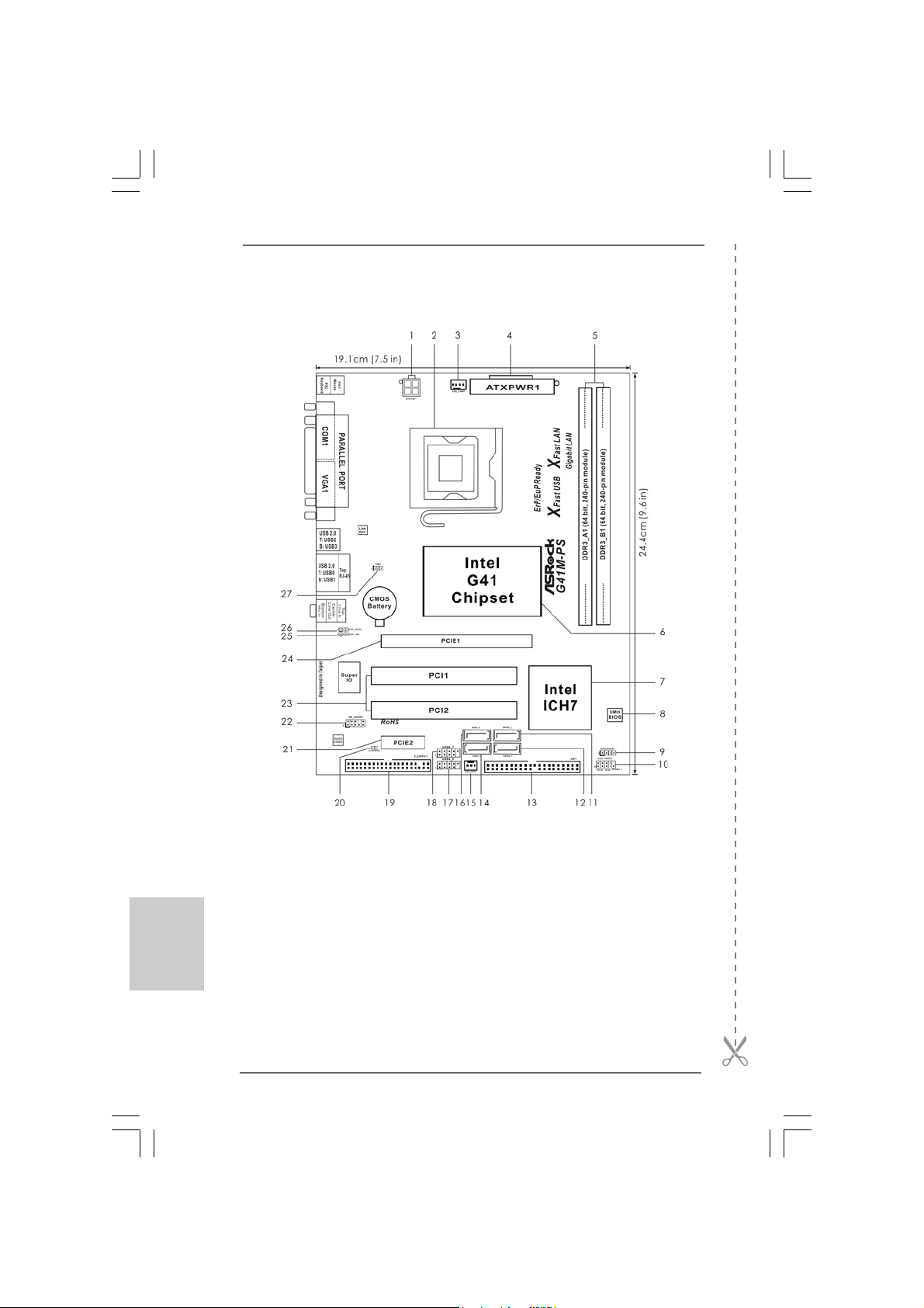
Motherboard LayoutMotherboard Layout
Motherboard Layout
Motherboard LayoutMotherboard Layout
English
EnglishEnglish
EnglishEnglish
22
2
22
1 ATX 12V Connector (ATX12V1) 14 Third SATA2 Connector (SATAII_3; Blue)
2 775-Pin CPU Socket 15 Chassis Fan Connector (CHA_FAN1)
3 CPU Fan Connector (CPU_FAN1) 16 Fourth SATA2 Connector (SATAII_4; Blue)
4 ATX Power Connector (ATXPWR1) 17 USB 2.0 Header (USB4_5, Blue)
5 2 x 240-pin DDR3 DIMM Slots 18 USB 2.0 Header (USB6_7, Blue)
(Dual Channel: DDR3_A1, DDR3_B1; Blue) 19 Floppy Connector (FLOPPY1)
6 North Bridge Controller 20 Clear CMOS Jumper (CLRCMOS1)
7 South Bridge Controller 21 PCI Express x1 Slot (PCIE2)
8 BIOS SPI Chip 22 Front Panel Audio Header
9 Chassis Speaker Header (HD_AUDIO1, White)
(SPEAKER 1, White) 23 PCI Slots (PCI1- 2)
10 System Panel Header (PANEL1, White) 24 PCI Express x16 Slot (PCIE1)
11 Secondary SATA2 Connector (SATAII_2; Blue)25 EUP LAN Jumper (EUP_LAN1)
12 Primary SATA2 Connector (SATAII_1; Blue) 26 EUP Audio Jumper (EUP_AUDIO1)
13 IDE1 Connector (IDE1, Blue) 27 FSB1 Jumper
ASRock G41M-PS Motherboard
Page 3
I/O PI/O P
I/O P
I/O PI/O P
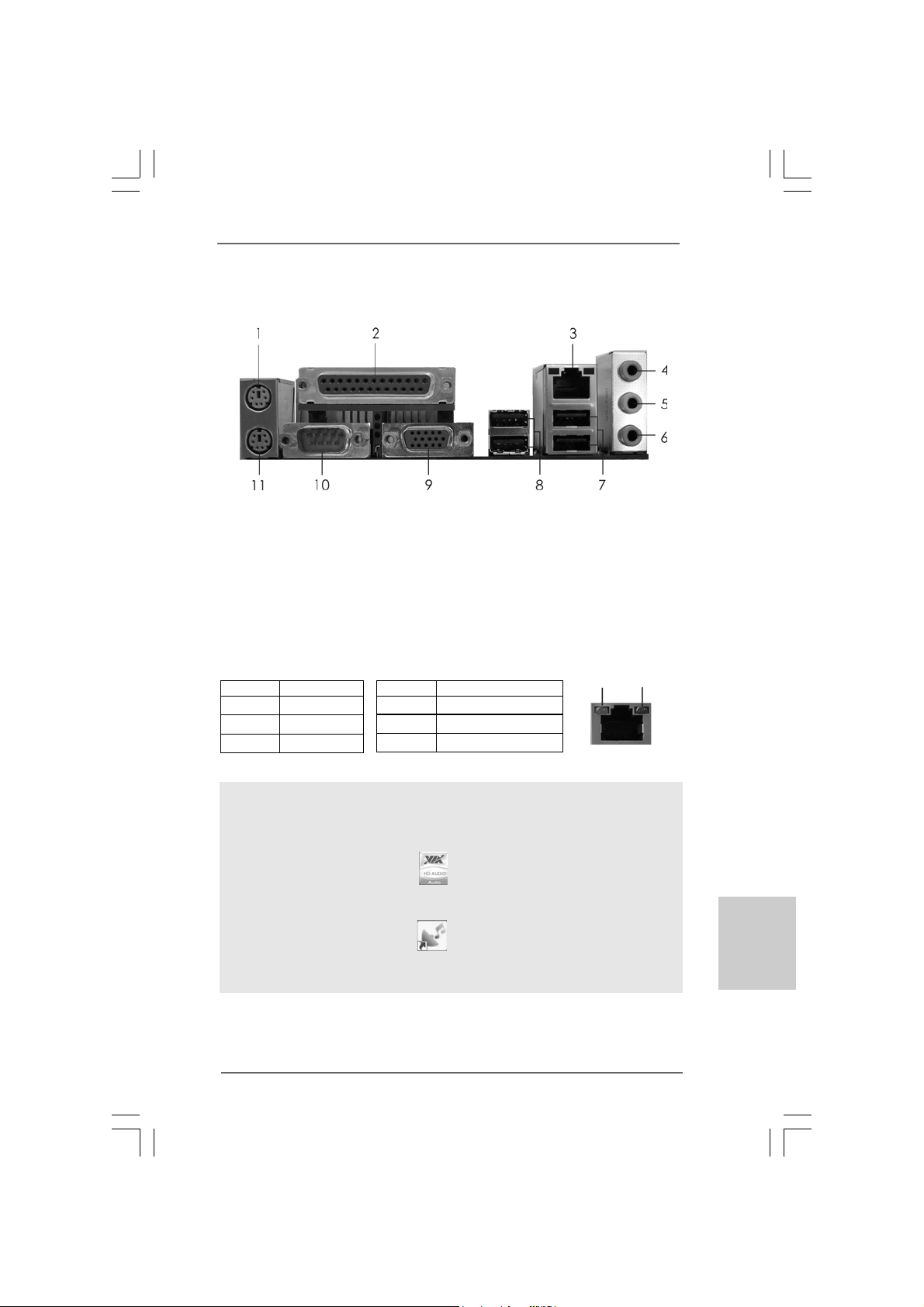
* There are two LED next to the LAN port. Please refer to the table below for the LAN port LED
indications.
anelanel
anel
anelanel
1 PS/2 Mouse Port (Green) 7 USB 2.0 Ports (USB01)
2 Parallel Port 8 USB 2.0 Ports (USB23)
3 RJ-45 Port 9 VGA Port
4 Line In (Light Blue) 10 COM Port
5 Line Out (Lime) 11 PS/2 Keyboard Port (Purple)
6 Microphone (Pink)
Activity/Link LED SPEED LED
Status Description Status Description
Off No Link Off 10Mbps connection
Blinking Data Activity Orange 100Mbps connection
On Link Green 1Gbps connection
LAN Port LED Indications
ACT/LINK
LED
LAN Port
SPEED
LED
To enable Multi-Streaming function, you need to connect a front panel audio cable to the front
panel audio header. After restarting your computer, you will find “VIA HD Audio Deck” tool on
your system. Please follow below instructions according to the OS you install.
For Windows® XP / XP 64-bit OS:
Please click “VIA HD Audio Deck” icon , and click “Speaker”. Then you are allowed to
select “2 Channel” or “4 Channel”. Click “Power” to save your change.
For Windows® 7 / 7 64-bit / VistaTM / VistaTM 64-bit OS:
Please click “VIA HD Audio Deck” icon , and click “Advanced Options” on the left side
on the bottom. In “Advanced Options” screen, select “Independent Headphone”, and click
“OK” to save your change.
ASRock G41M-PS Motherboard
EnglishEnglish
EnglishEnglish
English
33
3
33
Page 4

1. Introduction1. Introduction
1. Introduction
1. Introduction1. Introduction
Thank you for purchasing ASRock G41M-PS motherboard, a reliable motherboard produced under ASRock’s consistently stringent quality control. It delivers excellent performance with robust design conforming to ASRock’s commitment to quality a nd endurance.
This Quick Installation Guide contains introduction of the motherboard a nd step-by-step
installation guide. More detailed information of the motherboard can be f ound in the user
manual presented in the Support CD.
Because the motherboard specifications and the BIOS software might
be updated, the content of this manual will be subject to change without
notice. In case any modifications of this manual occur, the updated
version will be available on ASRock website without further notice. You
may find the latest VGA cards and CPU support lists on ASRock website
as well. ASRock website http://www.asrock.com
If you require technical support related to this motherboard, please visit
our website for specific information about the model you are using.
www.asrock.com/support/index.asp
1.1 P1.1 P
ackack
1.1 P
1.1 P1.1 P
ASRock G41M-PS Motherboard
(Micro ATX Form Factor: 9.6-in x 7.5-in, 24.4 cm x 19.1 cm)
ASRock G41M-PS Quick Installation Guide
ASRock G41M-PS Support CD
Two Serial ATA (SAT A) Data Cables (Optional)
One I/O Panel Shield
age Contentsage Contents
ack
age Contents
ackack
age Contentsage Contents
English
EnglishEnglish
EnglishEnglish
44
4
44
ASRock G41M-PS Motherboard
Page 5

1.21.2
SpecificationsSpecifications
1.2
Specifications
1.21.2
SpecificationsSpecifications
Platform - Micro ATX Form Fa ctor: 9.6-in x 7.5-in, 24.4 cm x 19.1 cm
- Solid Capa citor f or CPU power
CPU - LGA 775 for Intel® CoreTM 2 Extreme / CoreTM 2 Quad / Core
2 Duo / Pentium® Dual Core / Celeron® Dual Core / Celeron®,
supporting Penryn Quad Core Yorkfield and Dual Core
Wolfdale processors
- Supports FSB1333/1066/800/533 MHz
- Supports Hyper-Threading Technology (see CAUTION 1)
- Supports Untied Overclocking Te chnology (see CAUTION 2)
- Supports EM64T CPU
Chipset - Northbridge: Intel® G41
- Southbridge: Intel® ICH7
Memory - Dual Channel DDR3 Memory Technology (see CAUTION 3)
- 2 x DDR3 DIMM slots
- Supports DDR3 1333(OC)/1066/800 non-ECC, un-buf fered
memory (see CAUTION 4)
- Max. capacity of system memory: 8GB (see CAUTION 5)
Expansion Slot - 1 x PCI Express x16 slot
- 1 x PCI Express x1 slot
- 2 x PCI slots
Graphics - Intel® Graphics Media Accelerator X4500
- Pixel Shader 4.0, DirectX 10
- Max. shared memory 1759MB (see CAUTION 6)
- Supports D-Sub with max. resolution up to 2048x1536 @ 60Hz
Audio - 5.1 CH HD Audio (VIA® VT1705 Audio Codec)
LAN - PCIE x1 Gigabit LAN 10/100/1000 Mb/s
- Atheros® AR8151
- Supports Wa ke-On-LAN
- Supports LAN Cable Detection
- Supports PXE
Rear Panel I/O I/O Panel
- 1 x PS/2 Mouse Port
- 1 x PS/2 Keyboard Port
- 1 x Parallel Port (ECP/EPP Support)
- 1 x Serial Port: COM1
- 1 x VGA Port
- 4 x Ready-to-Use USB 2.0 Ports
- 1 x RJ-45 LAN Port with LED (ACT/LINK LED a nd SPEED LED)
- HD Audio Jack: Line in / Front Speaker / M icrophone
TM
EnglishEnglish
EnglishEnglish
English
ASRock G41M-PS Motherboard
55
5
55
Page 6

English
EnglishEnglish
EnglishEnglish
Connector - 4 x SATA2 3.0 Gb/s connectors (No Support f or RAID and
“Hot Plug” functions) (see CAUTION 7)
- 1 x AT A100 IDE connector (supports 2 x IDE devices )
- 1 x Floppy connector
- CPU/Chassis FAN conne ctor
- 24 pin A TX power connector
- 4 pin 12V power connector
- Front panel audio connector
- 2 x USB 2.0 headers (support 4 USB 2.0 ports)
BIOS Feature - 8Mb AMI BIOS
- AMI Legal BIOS
- Supports “Plug and Play”
- ACPI 1.1 Compliance Wa ke Up Events
- AMBIOS 2.3.1 Support
- DRAM, NB, SB, VTT V oltage Multi-a djustment
Support CD - Drivers, Utilities, AntiV irus Software (T ri al Version), CyberLink
MediaEspresso 6.5 Tri al, ASRock Software Suite (CyberLink
DV D Suite - OEM and Trial; Creative Sound Bla ster X-Fi MB Trial; ASRock MAGIX Multimedia Suite - OEM)
Unique Feature - ASRock OC Tuner (see CAUTION 8)
- ASRock Intelligent Energy Saver (see CAUTION 9)
- ASRock Instant Boot
- ASRock Instant Flash (see CAUTION 10)
- ASRock OC DNA (see CAUTION 1 1)
- ASRock APP Charger (see CAUTION 12)
- ASRock SmartView (see CAUTION 13)
- ASRock XFast USB (see CAUTION 14)
- ASRock XFast LAN (see CAUTION 15)
- Hybrid Booster:
- CPU Frequency Stepless Control (see CAUTION 16)
- ASRock U-COP (see CAUTION 17)
- Boot Failure Guard (B.F.G.)
Hardware - CPU T e mperature Sensing
Monitor - Chassis Te mperature Sensing
- CPU Fan Ta chometer
- Chassis Fa n Tachometer
- CPU Quiet Fan
- Voltage Monitoring: +12V, +5V, +3.3V, Vcore
OS - Microsoft® Windows® 7 / 7 64-bit / Vista
/ XP / XP 64-bit complia nt
TM
/ VistaTM 64-bit
66
6
66
ASRock G41M-PS Motherboard
Page 7
Certifications - FCC, CE, WHQL
- ErP/EuP Ready (ErP/EuP ready power supply is required)
(see CAUTION 18)
* For detailed product information, please visit our website: http://www.asrock.com
WAR NING
Please realize that there is a certain risk involved with overclocking, including
adjusting the setting in the BIOS, applying Untied Overclocking Technology, or using
the third-party overclocking tools. Overclocking may affect your system stability, or
even cause damage to the components and devices of your system. It should be
done at your own risk and expense. We are not responsible for possible damage
caused by overclocking.
CAUTION!
1. About the setting of “Hyper Threading Technology”, please check page
34 of “User Manual” in the support CD.
2. This motherboard supports Untied Overclocking Technology. Please read
“Untied Overclocking Technology” on page 20 for details.
3. This motherboard supports Dual Channel Memory Technology. Before
you implement Dual Channel Memory Technology, make sure to read
the installation guide of memory modules on page 13 for proper
installation.
4. Please check the table below for the CPU FSB frequency and its
corresponding memory support frequency.
CPU FSB Frequency Memory Support Frequency
1333 DDR3 800, DDR3 1066, DDR3 1333
1066 DDR3 800, DDR3 1066
800 DDR3 800
533 DDR3 800
* DDR3 1333 memory modules will operate in overclocking mode.
* When you use a FSB533-CPU on this motherboard, it will run at
DDR3 533 if you adopt a DDR3 800 memory module.
* If you adopt FSB1333-CPU and DDR3 1333 memory module on this
motherboard, you need to adjust the jumper. Please refer to page 16
for proper jumper settings.
5. Due to the operating system limitation, the actual memory size may be
less than 4GB for the reservation for system usage under Windows® 7
/ VistaTM / XP. For Windows® OS with 64-bit CPU, there is no such
limitation.
6. The maximum shared memory size is defined by the chipset vendor
and is subject to change. Please check Intel® website for the latest
information.
7. Before installing SATAII hard disk to SATAII connector, please read the “SATAII
Hard Disk Setup Guide” on page 24 of “User Manual” in the support CD to
adjust your SATAII hard disk drive to SATAII mode. You can also connect
SATA hard disk to SATAII connector directly.
EnglishEnglish
EnglishEnglish
English
ASRock G41M-PS Motherboard
77
7
77
Page 8
English
EnglishEnglish
EnglishEnglish
8. It is a user-friendly ASRock overclocking tool which allows you to surveil
your system by hardware monitor function and overclock your hardware
devices to get the best system performance under Windows
environment. Please visit our website for the operation procedures of
ASRock OC Tuner. ASRock website: http://www.asrock.com
9. Featuring an advanced proprietary hardware and software design,
Intelligent Energy Saver is a revolutionary technology that delivers
unparalleled power savings. In other words, it is able to provide exceptional power saving and improve power efficiency without sacrificing
computing performance. Please visit our website for the operation procedures of Intelligent Energy Saver.
ASRock website: http://www.asrock.com
10. ASRock Instant Flash is a BIOS flash utility embedded in Flash ROM.
This convenient BIOS update tool allows you to update system BIOS
without entering operating systems first like MS-DOS or Windows®.
With this utility, you can press <F6> key during the POST or press <F2>
key to BIOS setup menu to access ASRock Instant Flash. Just launch
this tool and save the new BIOS file to your USB flash drive, floppy disk
or hard drive, then you can update your BIOS only in a few clicks without
preparing an additional floppy diskette or other complicated flash utility.
Please be noted that the USB flash drive or hard drive must use FAT32/
16/12 file system.
11. The software name itself – OC DNA literally tells you what it is capable
of. OC DNA, an exclusive utility developed by ASRock, provides a convenient way for the user to record the OC settings and share with others.
It helps you to save your overclocking record under the operating system and simplifies the complicated recording process of overclocking
settings. With OC DNA, you can save your OC settings as a profile and
share with your friends! Your friends then can load the OC profile to their
own system to get the same OC settings as yours! Please be noticed
that the OC profile can only be shared and worked on the same
motherboard.
12. If you desire a faster, less restricted way of charging your Apple devices,
such as iPhone/iPod/iPad Touch, ASRock has prepared a wonderful
solution for you - ASRock APP Charger. Simply installing the APP Charger
driver, it makes your iPhone charged much quickly from your computer
and up to 40% faster than before. ASRock APP Charger allows you to
quickly charge many Apple devices simultaneously and even supports
continuous charging when your PC enters into Standby mode (S1),
Suspend to RAM (S3), hibernation mode (S4) or power off (S5). With
APP Charger driver installed, you can easily enjoy the marvelous charging experience than ever.
ASRock website: http://www.asrock.com/Feature/AppCharger/index.asp
®
88
8
88
ASRock G41M-PS Motherboard
Page 9
13. SmartView, a new function of internet browser, is the smart start page
for IE that combines your most visited web sites, your history, your
Facebook friends and your real-time newsfeed into an enhanced view
for a more personal Internet experience. ASRock motherboards are
exclusively equipped with the SmartView utility that helps you keep in
touch with friends on-the-go. To use SmartView feature, please make
sure your OS version is Windows® 7 / 7 64 bit / VistaTM / VistaTM 64 bit,
and your browser version is IE8.
ASRock website: http://www.asrock.com/Feature/SmartView/index.asp
14. ASRock XFast USB can boost USB storage device performance. The
performance may depend on the property of the device.
15. ASRock XFast LAN provides a faster internet access, which includes
below benefits. LAN Application Prioritization: You can configure your
application priority ideally and/or add new programs. Lower Latency in
Game: After setting online game priority higher, it can lower the latency
in game. Traffic Shaping: You can watch Youtube HD video and download files simultaneously. Real-Time Analysis of Your Data: With the
status window, you can easily recognize which data streams you are
currently transferring.
16. Although this motherboard offers stepless control, it is not recommended to perform over-clocking. Frequencies other than the recommended CPU bus frequencies may cause the instability of the system
or damage the CPU.
17. While CPU overheat is detected, the system will automatically shutdown.
Before you resume the system, please check if the CPU fan on the
motherboard functions properly and unplug the power cord, then plug it
back again. To improve heat dissipation, remember to spray thermal
grease between the CPU and the heatsink when you install the PC
system.
18. EuP, stands for Energy Using Product, was a provision regulated by
European Union to define the power consumption for the completed
system. According to EuP, the total AC power of the completed system
shall be under 1.00W in off mode condition. To meet EuP standard, an
EuP ready motherboard and an EuP ready power supply are required.
According to Intel’s suggestion, the EuP ready power supply must meet
the standard of 5v standby power efficiency is higher than 50% under
100 mA current consumption. For EuP ready power supply selection,
we recommend you checking with the power supply manufacturer for
more details.
ASRock G41M-PS Motherboard
EnglishEnglish
EnglishEnglish
English
99
9
99
Page 10
2.2.
InstallationInstallation
2.
Installation
2.2.
InstallationInstallation
Pre-installation PrecautionsPre-installation Precautions
Pre-installation Precautions
Pre-installation PrecautionsPre-installation Precautions
Take note of the following precautions before you install motherboard components or change any motherboard settings.
1. Unplug the power cord from the wall socket before touching any
component. Failure to do so may cause severe damage to the
motherboard, peripherals, and/or components.
2. To avoid damaging the motherboard components due to static
electricity, NEVER place your motherboard directly on the carpet
or the like. Also remember to use a grounded wrist strap or touch
a safety grounded object before you handle components.
3. Hold components by the edges and do not touch the ICs.
4. Whenever you uninstall any component, place it on a grounded
antstatic pad or in the bag that comes with the component.
5. When placing screws into the screw holes to secure the
motherboard to the chassis, please do not over-tighten the
screws! Doing so may damage the motherboard.
2.12.1
CPU InstallationCPU Installation
2.1
CPU Installation
2.12.1
CPU InstallationCPU Installation
For the installation of Intel 775-LAND CPU,
please follow the steps below.
English
EnglishEnglish
EnglishEnglish
1010
10
1010
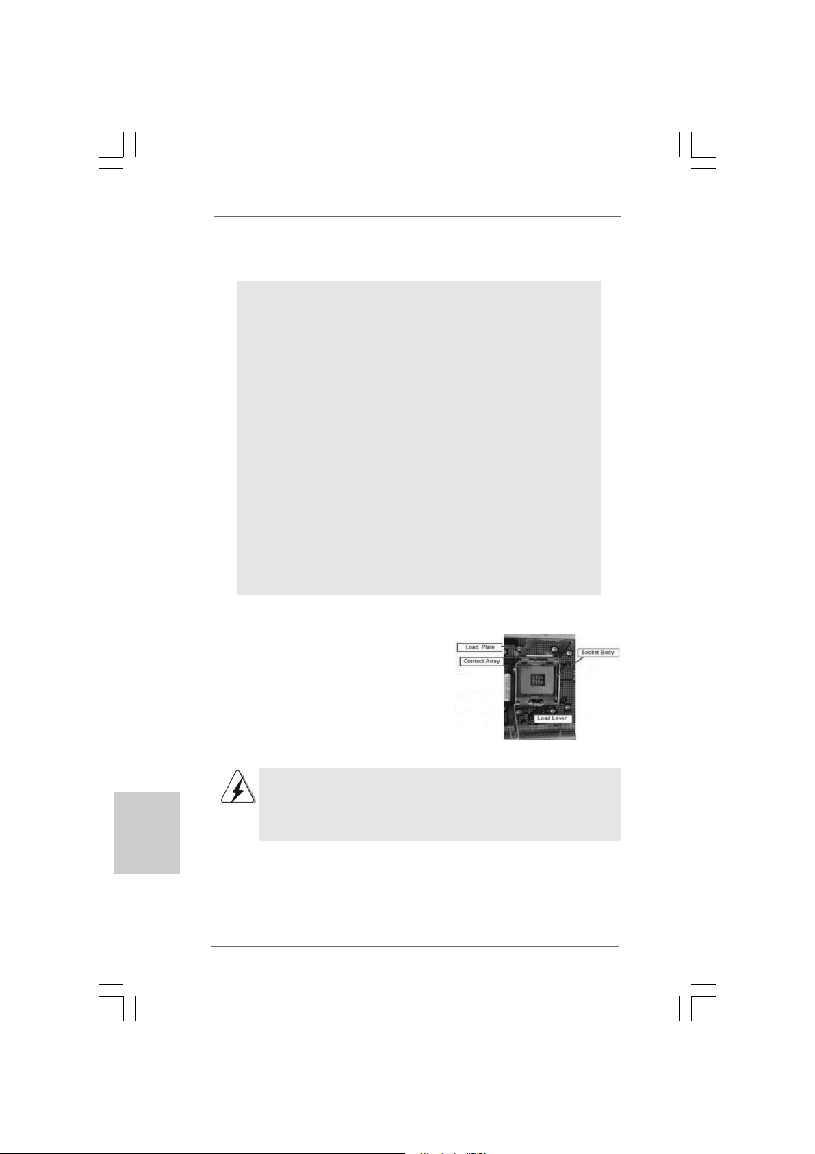
775-Pin Socket Overview
Before you insert the 775-LAND CPU into the socket, please check if
the CPU surface is unclean or if there is any bent pin on the socket.
Do not force to insert the CPU into the socket if above situation is
found. Otherwise, the CPU will be seriously damaged.
ASRock G41M-PS Motherboard
Page 11
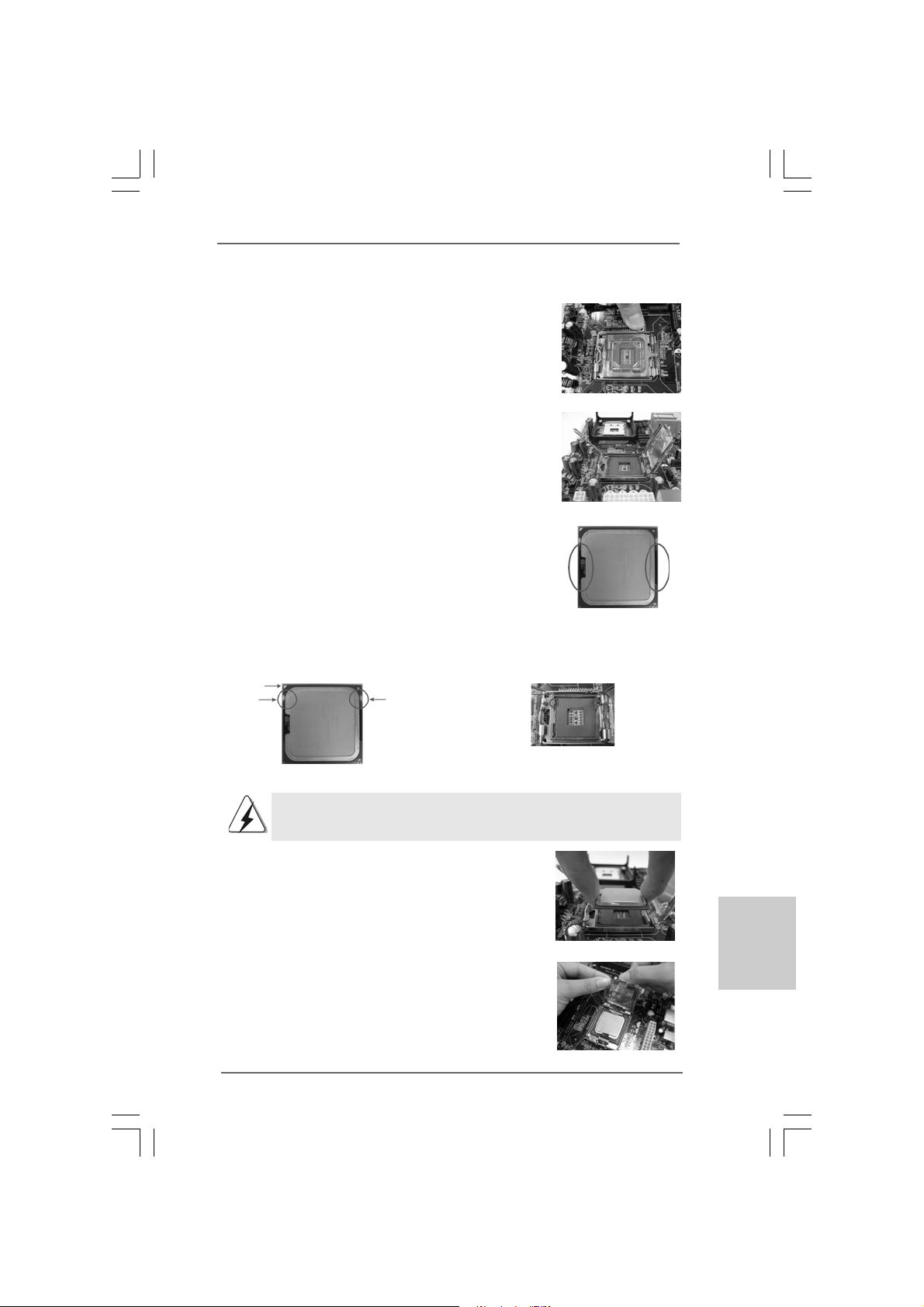
Step 1. Open the socket:
Step 1-1. Disengaging the lever by depressing
down and out on the hook to clear
retention tab.
Step 1-2. Rotate the load lever to fully open po-
sition at approximately 135 degrees.
Step 1-3. Rotate the load plate to fully open po-
sition at approximately 100 degrees.
Step 2. Insert the 775-LAND CPU:
Step 2-1. Hold the CPU by the edges where are
marked with black lines.
Step 2-2. Orient the CPU with IHS (Integrated
Heat Sink) up. Locate Pin1 and the two
orientation key notches.
Pin1
orientation
key notch
orientation
key notch
Pin1
alignment key
black line
black line
alignment key
775-LAND CPU
For proper inserting, please ensure to match the two orientation key
notches of the CPU with the two alignment keys of the socket.
Step 2-3. Carefully place the CPU into the socket
by using a purely vertical motion.
Step 2-4. Verify that the CPU is within the socket
and properly mated to the orient keys.
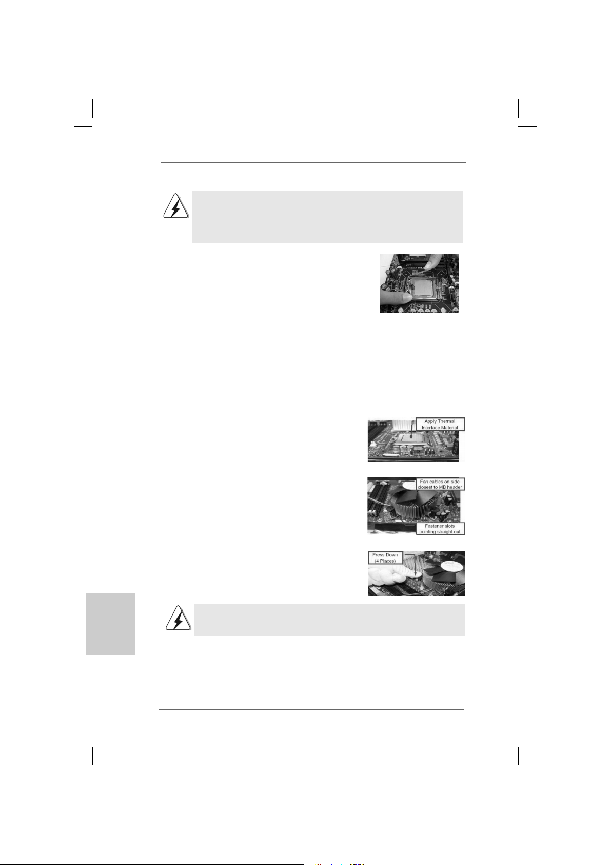
Step 3. Remove PnP Cap (Pick and Place Cap):
Use your left hand index finger and thumb to
support the load plate edge, engage PnP cap
with right hand thumb and peel the cap from the
socket while pressing on center of PnP cap to
assist in removal.
ASRock G41M-PS Motherboard
775-Pin Socket
1111
11
1111
EnglishEnglish
EnglishEnglish
English
Page 12
English
EnglishEnglish
EnglishEnglish
1. It is recommended to use the cap tab to handle and avoid kicking
off the PnP cap.
2. This cap must be placed if returning the motherboard for after
service.
Step 4. Close the socket:
Step 4-1. Rotate the load plate onto the IHS.
Step 4-2. While pressing down lightly on load
plate, engage the load lever.
Step 4-3. Secure load lever with load plate tab
under retention tab of load lever.
2.22.2
Installation of CPU Fan and HeatsinkInstallation of CPU Fan and Heatsink
2.2
Installation of CPU Fan and Heatsink
2.22.2
Installation of CPU Fan and HeatsinkInstallation of CPU Fan and Heatsink
For proper installation, please kindly refer to the instruction manuals of your CPU fan
and heatsink.
Below is an example to illustrate the installation of the heatsink for 775-LAND CPU.
Step 1. Apply thermal interface material onto center
of IHS on the socket surface.
Step 2. Place the heatsink onto the socket. Ensure
fan cables are oriented on side closest to the
CPU fan connector on the motherboard
(CPU_FAN1, see page 2, No. 3).
Step 3. Align fasteners with the motherboard
throughholes.
Step 4. Rotate the fastener clockwise, then press
down on fastener caps with thumb to install
and lock. Repeat with remaining fasteners.
If you press down the fasteners without rotating them clockwise,
the heatsink cannot be secured on the motherboard.
Step 5. Connect fan header with the CPU fan
connector on the motherboard.
Step 6. Secu r e exces s cable with tie-wrap to ensure
cable does not interfere with fan operation or
contact other components.
1212
12
1212
ASRock G41M-PS Motherboard
Page 13
2.3 Installation of Memor2.3 Installation of Memor
2.3 Installation of Memor
2.3 Installation of Memor2.3 Installation of Memor
G41M-PS motherboard provides two 240-pin DDR3 (Double Data Rate 3) DIMM slots,
and supports Dual Channel Memory Technology. For dual channel configuration, you
always need to install two identical (the same bra nd, speed, size and chi p-type) memory
modules in the DDR3 DIMM slots to activate Dual Channel Memory T echnology . Otherwise,
it will operate at single channel mode.
1. It is not allowed to install a DDR or DDR2 memory module into
DDR3 slot;otherwise, this motherboard and DIMM may be
damaged.
2. If you install only one memory module or two non-identical memory
modules, it is unable to activate the Dual Channel Memory
Technology.
Installing a DIMMInstalling a DIMM
Installing a DIMM
Installing a DIMMInstalling a DIMM
Please make sure to disconnect power supply before adding or
removing DIMMs or the system components.
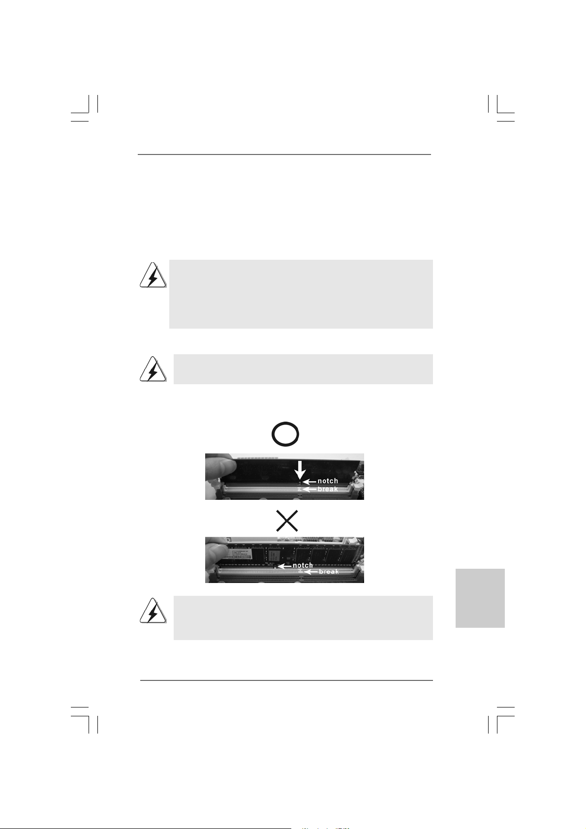
Step 1. Unlock a DIMM slot by pressing the retaining clips outward.
Step 2. Align a DIMM on the slot such that the notch on the DIMM matches the brea k
on the slot.
y Modules (DIMM)y Modules (DIMM)
y Modules (DIMM)
y Modules (DIMM)y Modules (DIMM)
The DIMM only fits in one correct orientation. It will cause permanent
damage to the motherboard and the DIMM if you force the DIMM into the
slot at incorrect orientation.
Step 3. Firmly insert the DIMM into the slot until the retaining cli ps at both ends fully
sna p back in place a nd the DIMM is properly seated.
ASRock G41M-PS Motherboard
1313
13
1313
EnglishEnglish
EnglishEnglish
English
Page 14
2.4 Expansion Slots (PCI and PCI Express Slots)2.4 Expansion Slots (PCI and PCI Express Slots)
2.4 Expansion Slots (PCI and PCI Express Slots)
2.4 Expansion Slots (PCI and PCI Express Slots)2.4 Expansion Slots (PCI and PCI Express Slots)
There are 2 PCI slots and 2 PCI Express slots on this motherboard.
PCI slots: PCI slots are used to install expansion cards that have the 32-bit PCI
interface.
PCIE slots:
PCIE1 (PCIE x16 slot) is used for PCI Express cards with x16 lane
width graphics cards.
PCIE2 (PCIE x1 slot) is used for PCI Express cards with x1 lane width
cards, such as Gigabit LAN card, SATA2 card, etc.
If you install the add-on PCI Express VGA card to PCIE1 (PCIE x16 slot),
the onboard VGA will be disabled. If you install the add-on PCI Express
VGA card to PCIE1 (PCIE x16 slot) and adjust the BIOS options “Primary
Graphics Adapter” to [Onboard] and “Share Memory” to [Auto], then the
onboard VGA will be enabled, and the primary screen will be onboard
VGA.
Installing an expansion cardInstalling an expansion card
Installing an expansion card
Installing an expansion cardInstalling an expansion card
Step 1. Before installing the expansion card, plea s e ma ke sure that the power supply
is switched off or the power cord is unplugged. Please rea d the documentation
of the expansion card a nd ma ke necessary hardware
settings for the card before you start the installation.
Step 2. Remove the bracket facing the slot that you intend to use. Keep the screws
for later use.
Step 3. Align the card connector with the slot and press firmly until the card is com-
pletely seated on the slot.
Step 4. Fasten the card to the chassis with screws.
English
EnglishEnglish
EnglishEnglish
1414
14
1414
ASRock G41M-PS Motherboard
Page 15

2.5 Jumpers Setup2.5 Jumpers Setup
2.5 Jumpers Setup
2.5 Jumpers Setup2.5 Jumpers Setup
The illustration shows how jumpers are setup.
When the jumper cap is placed on
pins, the jumper is “Short”. If no jumper cap is
placed on pins, the jumper is “Open”. The illustration shows a 3-pin jumper whose pin1
an d pin2 are “Short” when jumper cap is placed
on these 2 pins.
Jumper Setting Description
Clear CMOS
(CLRCMOS1, 2-pin jumper)
(see p.2 No. 20)
Note: CLRCMOS1 allows you to clear the data in CMOS. The data in CMOS includes
system setup information such as system password, date, time, and system
setup parameters. To clear and reset the system parameters to default setup,
please turn off the computer and unplug the power cord from the power supply.
After waiting for 15 seconds, use a jumper ca p to short 2 pins on CLRCMOS1 f or
5 seconds.
EUP LAN / EUP Audio Jumper
(EUP_LAN1, 3-pin jumper, see p.2 No. 25)
(EUP_AUDIO1, 3-pin jumper, see p.2 No. 26)
Note: EUP_LAN and EUP_AUDIO jumper design decreas es the power consumption of
this motherboard to meet EuP standard. With a n ASRock EuP rea dy motherboard
and a power supply that the 5VSB power efficiency is higher than 50% under
100mA current consumption, your system is able to submit EuP standard. The
default setting (short pin2 and pin3) is EuP disabled. If you want to enable this
power saving function, you may short pin1 and pin2. Plea se be noticed that when
EUP_LAN jumper is set to ena bled, the Wa ke-On-LAN function under S3 (Suspend
to RAM), S4 (Suspend to Disk), and S5 (Soft Off) will be disabled.
2-pin jumper
Short Open
Default (Disable EuP)
ASRock G41M-PS Motherboard
(Enable EuP)
1515
15
1515
EnglishEnglish
EnglishEnglish
English
Page 16

FSB1 Jumper
(FSB1, 3-pin jumper, see p.2 No. 27)
If you adopt FSB1333-CPU and DD R3 1333 memory module on this motherboard, you
need to adjust the jumper. Ple ase short pin2, pin3 for FSB1 jumper. Otherwise, the
CPU and memory module may not work properly on this motherboard. Please refer to
below jumper setting.
Default
English
EnglishEnglish
EnglishEnglish
1616
16
1616
ASRock G41M-PS Motherboard
Page 17

2.6 Onboard Headers and Connectors2.6 Onboard Headers and Connectors
2.6 Onboard Headers and Connectors
2.6 Onboard Headers and Connectors2.6 Onboard Headers and Connectors
Onboard headers and connectors are NOT jumpers. Do NOT place
jumper caps over these headers and connectors. Placing jumper
caps over the headers and connectors will cause permanent damage of the motherboard!
F DD connector
(33-pin FLOPPY1)
(see p.2 No. 19)
the red-striped side to
Pin1
Note: Make sure the red-striped side of the cable is plugged into Pin1 side of the
connector.
Primary IDE connector (Blue)
(39-pin IDE1, see p.2 No. 13)
connect the blue end
to the motherboard
connect the black end
to the IDE devices
80-conductor AT A 66/100 ca ble
Note: Please refer to the instruction of your IDE device vendor for the details.
Serial A TAII Connectors These Serial A TAII (SA T AII)
(SATAII_1: see p.2, No. 12) connectors support SATAII
(SATAII_2: see p.2, No. 11) or SATA hard disk f or internal
(SATAII_3: see p.2, No. 14) storage devices. The current
(SATAII_4: see p.2, No. 16) SA TAII interface allows up to
SATAII_4
SATAII_3
SATAII_2
SATAII_1
3.0 Gb/s data tra n s fer rate.
Serial A TA (SA T A) Either end of the SATA data cable
Data Cable can be connected to the SATA /
(Optional) SA TAII hard disk or the SA TAII
connector on the motherboard.
EnglishEnglish
EnglishEnglish
English
ASRock G41M-PS Motherboard
1717
17
1717
Page 18

USB 2.0 Headers Besides four default USB 2.0
(9-pin USB6_7) ports on the I/O panel, there are
(see p.2 No. 18) two USB 2.0 headers on this
motherboard. Each USB 2.0
header can support two USB
2.0 ports.
(9-pin USB4_5)
(see p.2 No. 17)
Front Panel Audio Hea der This is an interface f or front
(9-pin HD_AUDIO1) panel audio cable that allows
(see p.2 No. 22) convenient connection and
control of audio devices.
1. High Definition Audio supports Jack Sensing, but the panel wire on
the chassis must support HDA to function correctly. Please follow the
instruction in our manual and chassis manual to install your system.
2. If you use AC’97 audio panel, please install it to the front panel audio
header as below:
A. Connect Mic_IN (MIC) to MIC2_L.
B. Connect Audio_R (RIN) to OUT2_R and Audio_L (LIN) to OUT2_L.
C. Connect Ground (GND) to Ground (GND).
D. MIC_RET and OUT_RET are for HD audio panel only. You don’t
need to connect them for AC’97 audio panel.
English
EnglishEnglish
EnglishEnglish
1818
18
1818
System Panel Header This header accommodates
(9-pin PANEL1) several system front pa nel
(see p.2 No. 10) functions.
Chassis Spea ker Hea der Please connect the chassis
(4-pin SPEAKER 1) speaker to this header.
(see p.2 No. 9)
ASRock G41M-PS Motherboard
Page 19

Cha ssis Fan Conne ctor Please connect a chassis fan
(3-pin CHA_FAN1) cable to this connector and
(see p.2 No. 15) match the black wire to the
ground pin.
CPU Fan Connector Please connect a CPU fan cable
(4-pin CPU_FAN1) to this connector and match
(see p.2 No. 3) the black wire to the ground pin.
Though this motherboard provides 4-Pin CPU fan (Quiet Fan) support, the 3-Pin
CPU fan still can work successfully even without the fan speed control function.
If you plan to connect the 3-Pin CPU fan to the CPU fan connector on this
motherboard, please connect it to Pin 1-3.
1 2 3 4
Pin 1-3 Connected
3-Pin Fan Installation
ATX Power Conne ctor Please connect an A TX power
(24-pin ATXPWR1) supply to this connector.
(see p.2 No. 4)
Though this motherboard provides 24-pin ATX power connector, it can still
work if you adopt a traditional 20-pin ATX power supply. To use the 20-pin
ATX power supply, please plug your power supply along with Pin 1 and Pin 13.
24 13
12 1
20-Pin ATX Power Supply Installation
24 13
12 1
ATX 12V Connector Please note that it is necessary
(4-pin ATX12V1) to connect a power supply with
(see p.2 No. 1) A TX 12V plug to this connector
so that it can provides sufficient
power. Failing to do so will cause
the failure to power up.
EnglishEnglish
EnglishEnglish
English
ASRock G41M-PS Motherboard
1919
19
1919
Page 20

2.72.7
Serial ASerial A
2.7
Serial A
2.72.7
Serial ASerial A
Installation Installation
Installation
Installation Installation
This motherboard adopts Intel® ICH7 south bridge chipset that supports Serial ATA
(SATA) / Serial ATAII (SAT AII) hard dis k s. You may install SATA / SAT AII hard dis k s on
this motherboard for internal storage devices. This section will guide you to install the
SATA / SATAII hard disks.
STEP 1: Install the SATA / SATAII hard disks into the drive bays of your chassis.
STEP 2: Connect the SATA power ca ble to the SATA / SATAII hard disk.
STEP 3: Connect one end of the SATA data ca ble to the motherboard’s SAT AII
connector.
STEP 4: Connect the other end of the SATA data ca ble to the SATA / SATAII hard
disk.
2.82.8
Driver Installation GuideDriver Installation Guide
2.8
Driver Installation Guide
2.82.8
Driver Installation GuideDriver Installation Guide
To install the drivers to your system, please insert the support CD to your optical drive
first. Then, the drivers compatible to your system can be auto-detected and listed on
the support CD driver page. Please follow the order from up to bottom side to install
those required drivers. Therefore, the drivers you install can work properly.
2.92.9
Untied Overclocking TUntied Overclocking T
2.9
Untied Overclocking T
2.92.9
Untied Overclocking TUntied Overclocking T
This motherboard supports Untied Overclocking Technology, which means during
overclocking, FSB enjoys better margin due to fixed PCI / PCIE buses. Before you
enable Untied Overclocking function, plea se enter “Overclock Mode” option of BIOS setup
to set the selection from [Auto] to [Manual]. Therefore, CPU FSB is untied during
overclocking, but PCI / PCIE buses are in the fixed mode so that FSB can operate under
a more stable overclocking environment.
TT
A (SAA (SA
T
A (SA
TT
A (SAA (SA
TT
A) / Serial AA) / Serial A
T
A) / Serial A
TT
A) / Serial AA) / Serial A
echnologyechnology
echnology
echnologyechnology
TT
AII (SAAII (SA
T
AII (SA
TT
AII (SAAII (SA
TT
AII) Hard DisksAII) Hard Disks
T
AII) Hard Disks
TT
AII) Hard DisksAII) Hard Disks
English
EnglishEnglish
EnglishEnglish
2020
20
2020
Please refer to the warning on page 7 for the possible overclocking risk
before you apply Untied Overclocking Technology.
ASRock G41M-PS Motherboard
Page 21

3. BIOS Information3. BIOS Information
3. BIOS Information
3. BIOS Information3. BIOS Information
The Flash Memory on the motherboard stores BIOS Setup Utility. When you start up
the computer, please press <F2> during the Power-On-Self-Test (POST) to enter
BIOS Setup utility; otherwise, POST continues with its test routines. If you wish to
enter BIOS Setup after POST, please restart the system by pressing <Ctl> + <Alt> +
<Delete>, or pressing the reset button on the system chassis. The BIOS Setup program is designed to be user-friendly. It is a menu-driven program, which allows you to
scroll through its various sub-menus and to select among the predetermined choices.
For the detailed information about BIOS Setup, please refer to the User Manual (PDF
file) contained in the Support CD.
4. Sof4. Sof
4. Sof
4. Sof4. Sof
This motherboard supports various Microsoft® Windows® operating systems: 7 /
7 64-bit / VistaTM / Vista
motherboard contains necessary drivers and useful utilities that will enhance
motherboard features. To begin using the Support CD, insert the CD into your CDROM drive. It will display the Main Menu automatically if “AUTORUN” is enabled in
your computer. If the Main Menu does not appear automatically, locate and doubleclick on the file “ASSETUP.EXE” from the BIN folder in the Support CD to display the
menus.
tware Supportware Suppor
tware Suppor
tware Supportware Suppor
TM
64-bit / XP / XP 64-bit. The Support CD that came with the
t CD informationt CD information
t CD information
t CD informationt CD information
EnglishEnglish
EnglishEnglish
English
ASRock G41M-PS Motherboard
2121
21
2121
Page 22

2222
22
2222
ASRock G41M-PS Motherboard
Page 23

ASRock G41M-PS Motherboard
2323
23
2323
Page 24

2424
24
2424
ASRock G41M-PS Motherboard
Page 25

ASRock G41M-PS Motherboard
2525
25
2525
Page 26

2626
26
2626
ASRock G41M-PS Motherboard
Page 27

ASRock G41M-PS Motherboard
2727
27
2727
Page 28

2828
28
2828
ASRock G41M-PS Motherboard
Page 29

Short Open
ASRock G41M-PS Motherboard
2929
29
2929
Page 30

3030
30
3030
ASRock G41M-PS Motherboard
Page 31

SATAII_4
SATAII_2
SATAII_3
SATAII_1
ASRock G41M-PS Motherboard
3131
31
3131
Page 32

3232
32
3232
ASRock G41M-PS Motherboard
Page 33

1 2 3 4
24 13
12 1
24 13
12 1
ASRock G41M-PS Motherboard
3333
33
3333
Page 34

3434
34
3434
ASRock G41M-PS Motherboard
Page 35

ASRock G41M-PS Motherboard
3535
35
3535
Page 36

®
®
® ®
®
®
®
®
®
3636
36
3636
ASRock G41M-PS Motherboard
Page 37

ASRock G41M-PS Motherboard
3737
37
3737
Page 38

®
®
3838
38
3838
®
®
®
ASRock G41M-PS Motherboard
Page 39

®
®
®
ASRock G41M-PS Motherboard
3939
39
3939
Page 40

®
4040
40
4040
ASRock G41M-PS Motherboard
Page 41

ASRock G41M-PS Motherboard
4141
41
4141
Page 42

SATAII_4
SATAII_2
4242
42
4242
SATAII_3
SATAII_1
ASRock G41M-PS Motherboard
Page 43

1 2 3 4
ASRock G41M-PS Motherboard
4343
43
4343
Page 44

24 13
12 1
24 13
12 1
4444
44
4444
® ®
ASRock G41M-PS Motherboard
Page 45

O:
X:
X O O O O O
X O O O O O
ASRock G41M-PS Motherboard
4545
45
4545
 Loading...