


Copyright Notice:Copyright Notice:
Copyright Notice:
Copyright Notice:Copyright Notice:
No part of this installation guide may be reproduced, transcribed, transmitted, or translated in any language, in any form or by any means, except duplication of documentation by the purchaser for backup purpose, without written consent of ASRock Inc.
Products and corporate names appearing in this guide may or may not be registered
trademarks or copyrights of their respective companies, and are used only for identification or explanation and to the owners’ benefit, without intent to infringe.
Disclaimer:Disclaimer:
Disclaimer:
Disclaimer:Disclaimer:
Specifications and information contained in this guide are furnished for informational
use only and subject to change without notice, and should not be constructed as a
commitment by ASRock. ASRock assumes no responsibility for any errors or omissions
that may appear in this guide.
With respect to the contents of this guide, ASRock does not provide warranty of any kind,
either expressed or implied, including but not limited to the implied warranties or
conditions of merchantability or fitness for a particular purpose. In no event shall
ASRock, its directors, officers, employees, or agents be liable for any indirect, special,
incidental, or consequential damages (including damages for loss of profits, loss of
business, loss of data, interruption of business and the like), even if ASRock has been
advised of the possibility of such damages arising from any defect or error in the guide
or product.
This device complies with Part 15 of the FCC Rules. Operation is subject to the
following two conditions:
(1) this device may not cause harmful interference, and
(2) this device must accept any interference received, including interference that
may cause undesired operation.
CALIFORNIA, USA ONLY
The Lithium battery adopted on this motherboard contains Perchlorate, a toxic
substance controlled in Perchlorate Best Management Practices (BMP) regulations
passed by the California Legislature. When you discard the Lithium battery in
California, USA, please follow the related regulations in advance.
“Perchlorate Material-special handling may apply, see
www.dtsc.ca.gov/hazardouswaste/perchlorate”
ASRock Website: http://www.asrock.com
Published December 2013
Copyright©2013 ASRock INC. All rights reserved.
ASRock G41C-GS / G41C-S Motherboard
EnglishEnglish
EnglishEnglish
English
11
1
11
Motherboard LMotherboard L
Motherboard L
Motherboard LMotherboard L
ayout (G41Cayout (G41C
ayout (G41C
ayout (G41Cayout (G41C
--
GS / G41CGS / G41C
-
GS / G41C
--
GS / G41CGS / G41C
-S)-S)
-S)
-S)-S)
3
24
1
5
6
19.8cm (7.8 in)
Keyboard
Mouse
PS2
PS2
COM1
1
PS2_USB_PWR1
ATX12V2
CPU_FAN1
30
VGA1
EuP Ready
FSB1333
DDR2 800
USB 2.0
T:USB2
B: USB3
USB 2.0
T: U SB 0
B: USB1
MicIn
29
28
27
26
25
24
23
1
Bottom:
1
LineOut
HD_AUDIO1
LPT1
CODEC
Center:
AUDIO
22
RoHS
Top:
RJ-45
LineIn
Top:
EUP_LAN
1
1
EUP_AUDIO1
Super
CMOS
Battery
LAN
PHY
PCIE2
IO
CLRCMOS1
FLOPPY1
21
Chipset
PCIE1
FSB1
1
PCI1
PCI2
Intel
G41
DX10
Intel
ICH7
IDE1
USB4_5
PANEL1
1
PLEDPWRBTN
8Mb
BIOS
1
1
HDLED RESET
USB6_7
17
1819
20
DDR3 1333
Dual Channel
16
FSB800
DDRII_1 (64bit, 240-pin module)
SATAII_1
SATAII_2
15
FSB800
FSB800
DDR3_A1 (64bit, 240-pin module)
DDRII_2 (64bit, 240-pin module)
SPEAKER1
1
14
FSB800
DDR3_B1 (64bit, 240-pin module)
PWR_FAN1
CHA_FAN1
SATAII_3
SATAII_4
24.4cm (9.6 in)
7
8
9
10
11
12
13
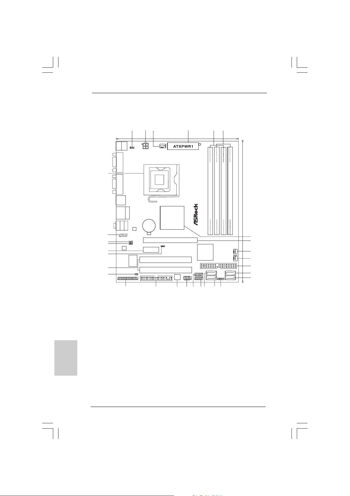
1 PS2_USB_PWR1 Jumper 16 Primary SAT AII Connector (SA T AII_1; Red)
2 ATX 12V Conne ctor (A TX12V2) 17 USB 2.0 Header (USB6_7, Blue)
3 CPU Fan Connector (CPU_FAN1) 18 USB 2.0 Header (USB4_5, Blue)
4 A TX Power Connector (ATXPWR1) 19 System Panel Header (PANEL1, Orange)
5 2 x 240-pin DDR2 DIMM Slots 20 BIOS SPI Chip
(Dual Channel: DDRII_1, DDRII_2; Yellow) 21 Floppy Connector (FLOPPY1)
English
EnglishEnglish
EnglishEnglish
6 2 x 240-pin DDR3 DIMM Slots 22 Print Port Header (LPT1, Purple)
(Dual Channel: DDR3_A1, DDR3_B1; Blue) 23 Clear CMOS Jumper (CLRCMOS1)
7 North Bridge Controller 24 PCI Slots (PCI1-2)
8 PCI Express x16 Slot (PCIE1) 25 FSB1 Jumper
9 Power Fan Connector (PWR_FAN1) 26 PCI Express x1 Slot (PCIE2)
10 Chassis Fan Connector (CHA_FAN1) 27 EUP Audio Jumper (EUP_AUDIO1)
11 IDE1 Connector (IDE1, Blue) 28 EUP LAN Jumper (EUP_LAN1)
12 Third SATAII Connector (SA TAII_3; Red) 29 Front Panel Audio Header
13 Fourth SATAII Connector (SATAII_4; Red) (HD_AUDIO1, Lime)
14 Chassis Speaker Header (SPEAKER 1, Purple) 30 775-Pin CPU Socket
15 Secondary SATAII Connector (SA T AII_2; Red)
22
2
22
ASRock G41C-GS / G41C-S Motherboard

I/O PI/O P
I/O P
I/O PI/O P
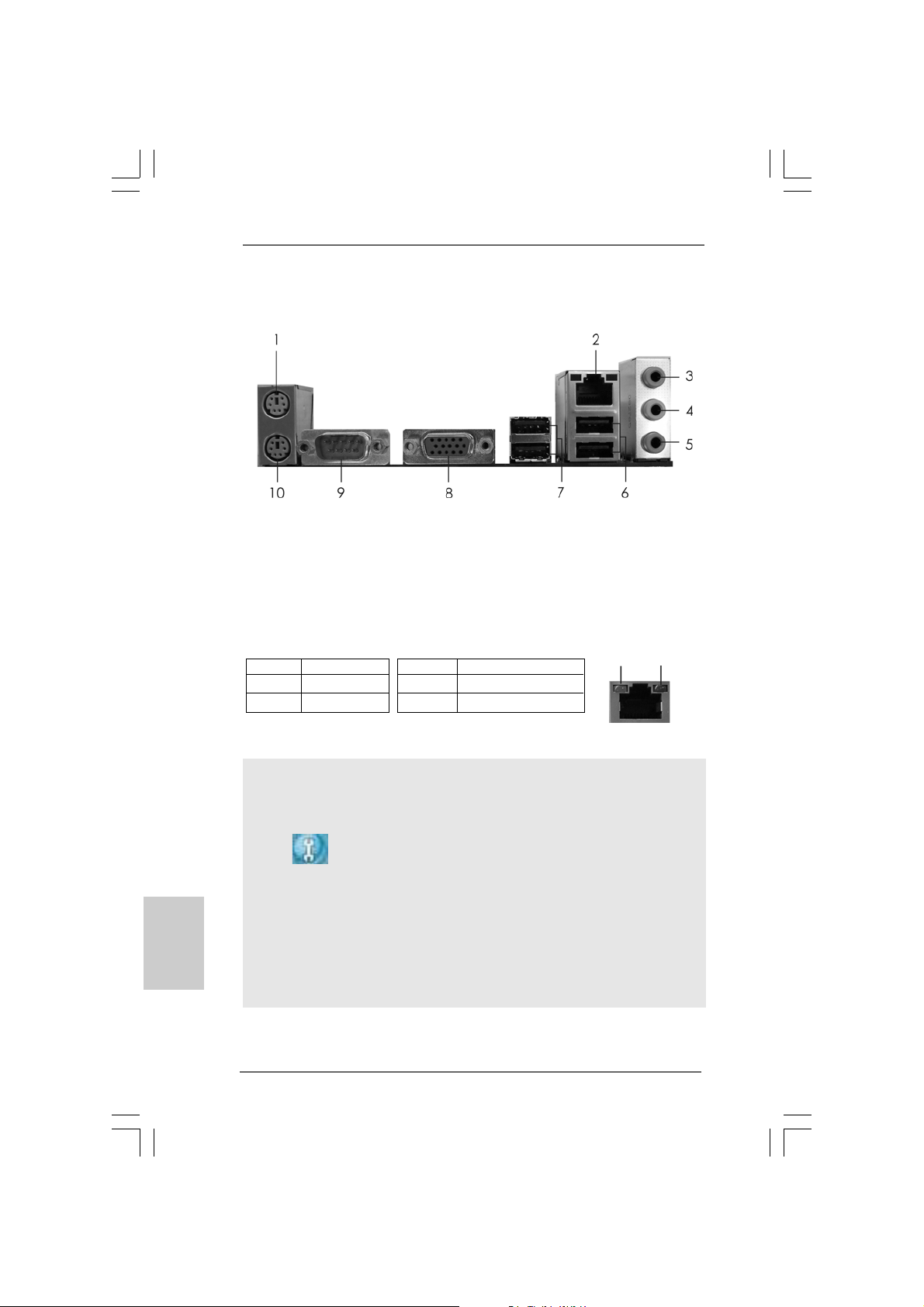
* 2 RJ-45 Port 7 USB 2.0 Ports (USB23)
anel (G41Canel (G41C
anel (G41C
anel (G41Canel (G41C
1 PS/2 Mouse Port (Green) 6 USB 2.0 Ports (USB01)
3 Line In (Light Blue) 8 VGA Port
4 Line Out (Lime) 9 COM Port
5 Microphone (Pink) 10 PS/2 Keyboard Port (Purple)
--
GS)GS)
-
GS)
--
GS)GS)
LAN Port LED Indications
Activity/Link LED SPEED LED
Status Description Status Description
Off No Activity Off 10Mbps connection
Blinking Data Activity Orange 100Mbps connection
Green 1Gbps connection
To enable Multi-Streaming function, you need to connect a front panel audio cable to the front
panel audio header. Please refer to below steps for the software setting of Multi-Streaming.
For Windows® XP:
After restarting your computer, you will find “Mixer” tool on your system. Please select “Mixer
ToolBox” , click “Enable playback multi-streaming”, and click “ok”. Choose “2CH” or
“4CH” and then you are allowed to select “Realtek HDA Primary output” to use Rear Speaker
and Front Speaker, or select “Realtek HDA Audio 2nd output” to use front panel audio. Then
reboot your system.
For Windows® 7 / VistaTM:
After restarting your computer, please double-click “Realtek HD Audio Manager” on the
system tray. Set “Speaker Configuration” to “Quadraphonic” or “Stereo”. Click “Device
advanced settings”, choose “Make front and rear output devices playbacks two different audio
streams simultaneously”, and click “ok”. Then reboot your system.
ASRock G41C-GS / G41C-S Motherboard
ACT/LINK
LED
SPEED
LED
LAN Port
EnglishEnglish
EnglishEnglish
English
33
3
33
I/O PI/O P
I/O P
I/O PI/O P
* 2 RJ-45 Port 7 USB 2.0 Ports (USB23)
anel (G41Canel (G41C
anel (G41C
anel (G41Canel (G41C
1 PS/2 Mouse Port (Green) 6 USB 2.0 Ports (USB01)
3 Line In (Light Blue) 8 VGA Port
4 Line Out (Lime) 9 COM Port
5 Microphone (Pink) 10 PS/2 Keyboard Port (Purple)
-S)-S)
-S)
-S)-S)
LAN Port LED Indications
Activity/Link LED SPEED LED
Status Description Status Description
Off No Activity Off 10Mbps connection
Blinking Data Activity Orange 100Mbps connection
To enable Multi-Streaming function, you need to connect a front panel audio cable to the front
panel audio header. Please refer to below steps for the software setting of Multi-Streaming.
For Windows® XP:
After restarting your computer, you will find “Mixer” tool on your system. Please select “Mixer
ToolBox” , click “Enable playback multi-streaming”, and click “ok”. Choose “2CH” or
“4CH” and then you are allowed to select “Realtek HDA Primary output” to use Rear Speaker
English
EnglishEnglish
EnglishEnglish
and Front Speaker, or select “Realtek HDA Audio 2nd output” to use front panel audio. Then
reboot your system.
For Windows® 7 / VistaTM:
After restarting your computer, please double-click “Realtek HD Audio Manager” on the
system tray. Set “Speaker Configuration” to “Quadraphonic” or “Stereo”. Click “Device
advanced settings”, choose “Make front and rear output devices playbacks two different audio
streams simultaneously”, and click “ok”. Then reboot your system.
44
4
44
ASRock G41C-GS / G41C-S Motherboard
ACT/LINK
LED
SPEED
LED
LAN Port

1. Introduction1. Introduction
1. Introduction
1. Introduction1. Introduction
Thank you for purchasing ASRock G41C-GS / G41C-S motherboard, a reliable
motherboard produced under ASRock’s consistently stringent quality control. It delivers excellent performance with robust design conforming to ASRock’s commitment to quality and endurance.
This Quick Installation Guide contains introduction of the motherboard and step-bystep installation guide. More detailed information of the motherboard can be found in
the user manual presented in the Support CD.
Because the motherboard specifications and the BIOS software might
be updated, the content of this manual will be subject to change without
notice. In case any modifications of this manual occur, the updated
version will be available on ASRock website without further notice. You
may find the latest VGA cards and CPU support lists on ASRock website
as well. ASRock website
If you require technical support related to this motherboard, please visit
our website for specific information about the model you are using.
www.asrock.com/support/index.asp
1.1 Package Contents1.1 Package Contents
1.1 Package Contents
1.1 Package Contents1.1 Package Contents
ASRock G41C-GS / G41C-S Motherboard
(Micro ATX Form Factor: 9.6-in x 7.8-in, 24.4 cm x 19.8 cm)
ASRock G41C-GS / G41C-S Quick Installation Guide
ASRock G41C-GS / G41C-S Support CD
Two Serial ATA (SATA) Data Cables (Optional)
One I/O Panel Shield
http://www.asrock.com
ASRock G41C-GS / G41C-S Motherboard
EnglishEnglish
EnglishEnglish
English
55
5
55
1.21.2
SpecificationsSpecifications
1.2
Specifications
1.21.2
SpecificationsSpecifications
Platform - Micro ATX Form Factor: 9.6-in x 7.8-in, 24.4 cm x 19.8 cm
CPU - LGA 775 for Intel® CoreTM 2 Extreme / CoreTM 2 Quad / Core
2 Duo / Pentium® Dual Core / Celeron® Dual Core / Celeron®,
supporting Penryn Quad Core Yorkfield and Dual Core
Wolfdale processors
- Supports FSB1333/1066/800/533 MHz
- Supports Hyper-Threading Technology
- Supports Untied Overclocking Technology
- Supports EM64T CPU
Chipset - Northbridge: Intel® G41
- Southbridge: Intel® ICH7
Memory - Dual Channel DDR3/DDR2 Memory Technology
- 2 x DDR3 DIMM slots
- Supports DDR3 1333(OC)/1066/800 non-ECC, un-buf fered
memory (see CAUTION 1)
- Max. capacity of system memory: 8GB (see CAUTION 2)
- 2 x DDR2 DIMM slots
- Supports DDR2 800/667/533 non-ECC, un-buf fered memory
(see CAUTION 1)
- Max. capacity of system memory: 8GB (see CAUTION 2)
Expansion Slot - 1 x PCI Express x16 slot
- 1 x PCI Express x1 slot
- 2 x PCI slots
Graphics - Intel® Graphics Media Accelerator X4500
- Pixel Shader 4.0, DirectX 10
- Max. shared memory 1759MB
- Supports D-Sub with max. resolution up to 2048x1536
@ 75Hz
Audio - 5.1 CH HD Audio (Realtek ALC662 / VIA® VT1705 Audio Codec)
LAN - G41C-GS:
English
EnglishEnglish
EnglishEnglish
Rear Panel I/O I/O Panel
Realtek PCIE x1 Gigabit LAN RTL81 11DL,
speed 10/100/1000 Mb/s
- G41C-S:
Realtek PCIE x1 LAN 8103EL / 8102EL, speed 10/100 Mb/s
- Supports Wa ke-On-LAN
- 1 x PS/2 Mouse Port
- 1 x PS/2 Keyboard Port
- 1 x Serial Port: COM1
TM
66
6
66
ASRock G41C-GS / G41C-S Motherboard

- 1 x VGA Port
- 4 x Ready-to-Use USB 2.0 Ports
- 1 x RJ-45 LAN Port with LED (ACT/LINK LED and SPEED LED)
- HD Audio Jack: Line in / Front Speaker / Microphone
Connector - 4 x SATAII 3.0 Gb/s connectors (No Support f or RAID and
“Hot Plug” functions)
- 1 x AT A100 IDE connector (supports 2 x IDE devices )
- 1 x Floppy connector
- 1 x Print port header
- CPU/Chassis/Power F A N connector
- 24 pin A TX power connector
- 4 pin 12V power connector
- Front panel audio connector
- 2 x USB 2.0 headers (support 4 USB 2.0 ports)
BIOS Feature - 8Mb AMI BIOS
- AMI Legal BIOS
- Supports “Plug and Play”
- ACPI 1.1 Compliance Wa ke Up Events
- SMBIOS 2.3.1 Support
- VCCM, NB, VTT, GTLRef Voltage Multi-adjustment
- Supports Smart BIOS
Support CD - Drivers, Utilities, AntiVirus Software (Trial Version), Google
Chrome Browser and Toolbar
Unique Feature - ASRock OC Tuner (see CAUTION 3)
- Intelligent Energy Saver (see CAUTION 4)
- Instant Boot
- ASRock Instant Flash (see CAUTION 5)
- ASRock OC DNA (see CAUTION 6)
- Hybrid Booster:
- CPU Frequency Stepless Control (see CAUTION 7)
- ASRock U-COP (see CAUTION 8)
- Boot Failure Guard (B.F.G.)
Hardware - CPU T e mperature Sensing
Monitor - Chassis Temperature Sensing
- CPU/Chassis/Power Fa n Tachometer
- CPU Quiet Fan
- Voltage Monitoring: +12V, +5V, +3.3V, Vcore
OS - Microsoft® Windows® 7 / 7 64-bit / Vista
XP / XP 64-bit complia nt
Certifications - FCC, CE
- EuP Ready (EuP ready power supply is required)
* For detailed product information, please visit our website:
ASRock G41C-GS / G41C-S Motherboard
TM
/ VistaTM 64-bit /
http://www.asrock.com
EnglishEnglish
EnglishEnglish
English
77
7
77
WARNING
Please realize that there is a certain risk involved with overclocking, including adjusting
the setting in the BIOS, applying Untied Overclocking Technology, or using the thirdparty overclocking tools. Overclocking may affect your system stability, or even
cause damage to the components and devices of your system. It should be done at
your own risk and expense. We are not responsible for possible damage caused by
overclocking.
CAUTION!
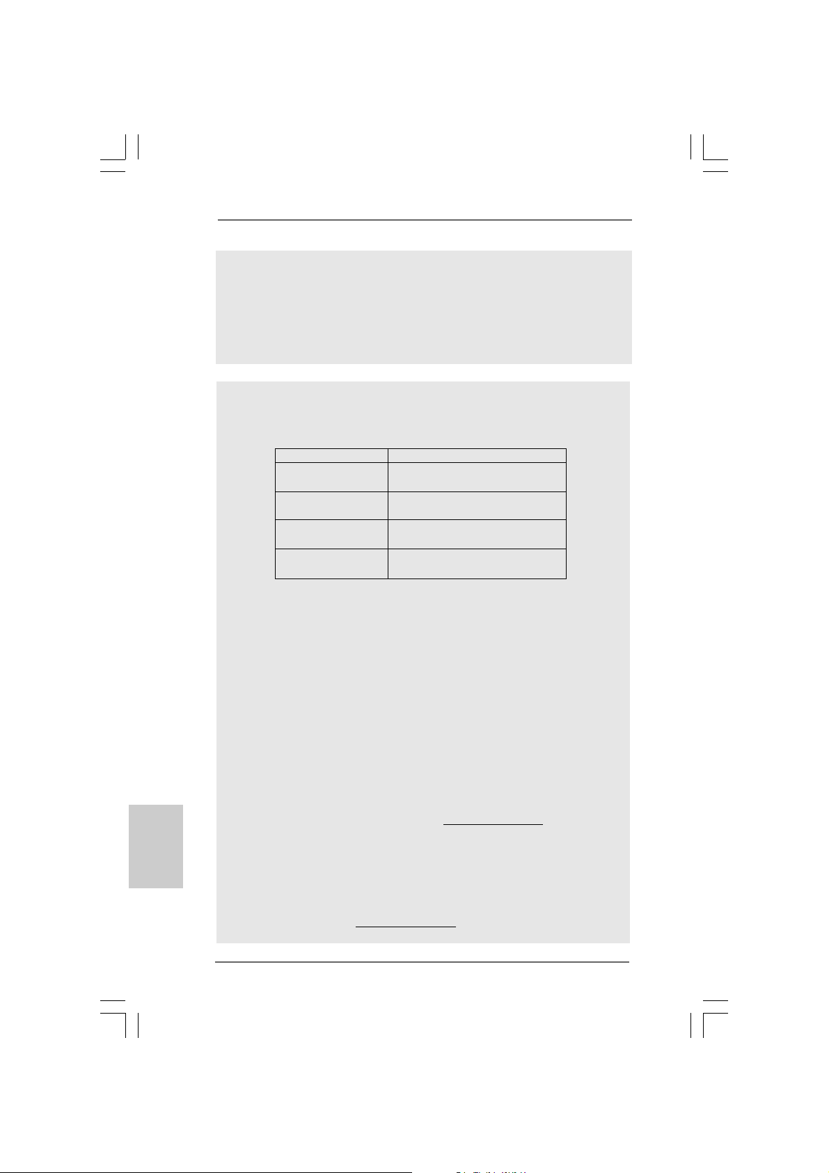
1. Please check the table below for the CPU FSB frequency and its
corresponding memory support frequency.
CPU FSB Frequency Memory Support Frequency
1333 DDR3 800, DDR3 1066, DDR3 1333
DDR2 667, DDR2 800
1066 DDR3 800, DDR3 1066
DDR2 667, DDR2 800
800 DDR3 800
DDR2 667, DDR2 800
533 DDR3 800
DDR2 533
* DDR3 1333 memory modules will operate in overclocking mode.
* When you use a FSB533-CPU on this motherboard, it will run at
DDR3 533 if you adopt a DDR3 800 memory module.
* If you adopt FSB1333-CPU and DDR3 1333 memory module on this
motherboard, you need to adjust the jumper. Please refer to page 11
for proper jumper settings.
2. Due to the operating system limitation, the actual memory size may be
less than 4GB for the reservation for system usage under Windows® 7
/ VistaTM / XP. For Windows® OS with 64-bit CPU, there is no such
limitation. In order to maximize the system memory, please install 4GB
memory module with 16 cells or 2GB memory modules with at least 8
cells.
3. It is a user-friendly ASRock overclocking tool which allows you to surveil
your system by hardware monitor function and overclock your hardware
devices to get the best system performance under Windows
English
EnglishEnglish
EnglishEnglish
environment. Please visit our website for the operation procedures of
ASRock OC Tuner. ASRock website:
4. Featuring an advanced proprietary hardware and software design,
Intelligent Energy Saver is a revolutionary technology that delivers
unparalleled power savings. In other words, it is able to provide exceptional power saving and improve power efficiency without sacrificing
computing performance. Please visit our website for the operation procedures of Intelligent Energy Saver.
ASRock website: http://www.asrock.com
http://www.asrock.com
®
88
8
88
ASRock G41C-GS / G41C-S Motherboard
5. ASRock Instant Flashis a BIOS flash utility embedded in Flash ROM.
This convenient BIOS update tool allows you to update system BIOS
without entering operating systems first like MS-DOS or Windows®. With
this utility, you can press <F6> key during the POST or press <F2> key to
BIOS setup menu to access ASRock Instant Flash. Just launch this tool
and save the new BIOS file to your USB flash drive, floppy disk or hard
drive, then you can update your BIOS only in a few clicks without preparing an additional floppy diskette or other complicated flash utility. Please
be noted that the USB flash drive or hard drive must use FAT32/16/12 file
system.
6. The software name itself – OC DNA literally tells you what it is capable
of. OC DNA, an exclusive utility developed by ASRock, provides a convenient way for the user to record the OC settings and share with others. It
helps you to save your overclocking record under the operating system
and simplifies the complicated recording process of overclocking settings.
With OC DNA, you can save your OC settings as a profile and share with
your friends! Your friends then can load the OC profile to their own system
to get the same OC settings as yours! Please be noticed that the OC
profile can only be shared and worked on the same motherboard.
7. Although this motherboard offers stepless control, it is not recommended to perform over-clocking. Frequencies other than the recommended CPU bus frequencies may cause the instability of the system
or damage the CPU.
8. While CPU overheat is detected, the system will automatically shutdown.
Before you resume the system, please check if the CPU fan on the
motherboard functions properly and unplug the power cord, then plug it
back again. To improve heat dissipation, remember to spray thermal
grease between the CPU a nd the he atsink when you in stall the PC system.
ASRock G41C-GS / G41C-S Motherboard
EnglishEnglish
EnglishEnglish
English
99
9
99
1.3 Jumpers Setup1.3 Jumpers Setup
1.3 Jumpers Setup
1.3 Jumpers Setup1.3 Jumpers Setup
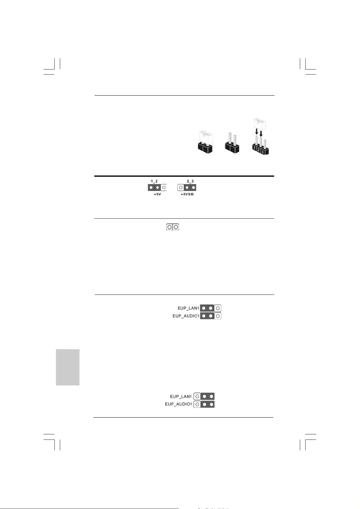
The illustration shows how jumpers are
setup. When the jumper cap is placed on
pins, the jumper is “Short”. If no jumper cap
is placed on pins, the jumper is “Open”. The
illustration shows a 3-pin jumper whose pin1
and pin2 are “Short” when jumper cap is
placed on these 2 pins.
Jumper Setting Description
PS2_USB_PWR1 Short pin2, pin3 to enable
(see p.2 No. 1) +5VSB (standby) for PS/2
Note: To select +5VSB, it requires 2 Amp and higher standby current provided by
power supply.
Clear CMOS
(CLRCMOS1, 2-pin jumper)
(see p.2 No. 23)
Note: CLRCMOS1 allows you to clear the data in CMOS. The data in CMOS includes
system setup information such as system password, date, time, and system
setup parameters. To clear and reset the system parameters to default setup,
please turn off the computer and unplug the power cord from the power
supply. After waiting for 15 seconds, use a jumper cap to short 2 pins on
CLRCMOS1 for 5 seconds.
2-pin jumper
Short Open
or USB wake up events.
EUP LAN / EUP Audio Jumper
(EUP_LAN1, 3-pin jumper, see p.2 No. 28)
(EUP_AUDIO1, 3-pin jumper, see p.2 No. 27)
Note: EUP_LAN and EUP_AUDIO jumper design decreases the power consumption
of this motherboard to meet EuP standard. With an ASRock EuP ready
motherboard and a power supply that the 5VSB power efficiency is higher
English
EnglishEnglish
EnglishEnglish
1010
10
1010
than 50% under 100mA current consumption, your system is able to submit
EuP standard. The default setting (short pin1 and pin2) is EuP enabled. If you
want to disable this power saving function, you may short pin2 and pin3.
Please be noticed that when EUP_LAN jumper is set to enabled, the
Wake-On-LAN function under S3 (Suspend to RAM), S4 (Suspend to Disk),
and S5 (Soft Off) will be disabled.
ASRock G41C-GS / G41C-S Motherboard
Default (Enable EuP)
(Disable EuP)
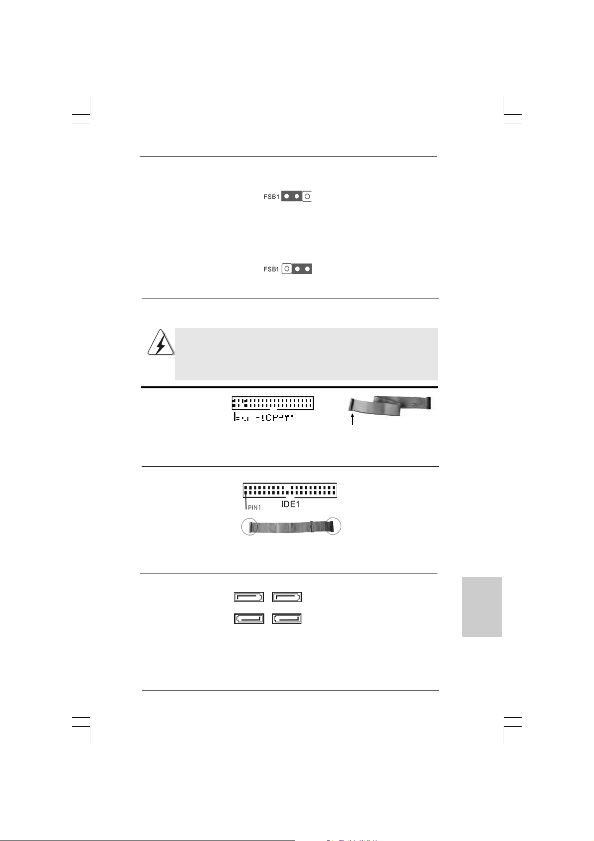
FSB1 Jumper
(FSB1, 3-pin jumper, see p.2 No. 25)
Default
If you adopt FSB1333-CPU and D DR3 1333 memory module on this motherboard, you
need to adjust the jumper. Please short pin2, pin3 for FSB1 jumper. Otherwise, the
CPU and memory module may not work properly on this motherboard. Please refer to
below jumper setting.
1.4 Onboard Headers and Connectors1.4 Onboard Headers and Connectors
1.4 Onboard Headers and Connectors
1.4 Onboard Headers and Connectors1.4 Onboard Headers and Connectors
Onboard headers and connectors are NOT jumpers. Do NOT place
jumper caps over these headers and connectors. Placing jumper caps
over the headers and connectors will cause permanent damage of the
motherboard!
Floppy Connector
(33-pin FLOPPY1)
(see p.2 No. 21)
the red-striped side to Pin1
Note: Make sure the red-striped side of the cable is plugged into Pin1 side of the
connector.
Primary IDE connector (Blue)
(39-pin IDE1, see p.2 No. 1 1)
connect the blue end
to the motherboard
connect the black end
to the IDE devices
80-conductor ATA 66/100 cable
Note: Please refer to the instruction of your IDE device vendor for the details.
Serial A T AII Connectors These four Serial ATAII (SATAII)
(SAT AII_1: see p.2, No. 16) connectors support SATAII
(SAT AII_2: see p.2, No. 15) or SATA hard disk for internal
(SAT AII_3: see p.2, No. 12) storage devices. The current
(SAT AII_4: see p.2, No. 13) SATAII interface allows up to
SATAII_1 SATAII_3
SATAII_2 SATAII_4
3.0 Gb/s data transfer rate.
ASRock G41C-GS / G41C-S Motherboard
1111
11
1111
EnglishEnglish
EnglishEnglish
English

Serial A TA (SA TA) Either end of the SATA data cable
Data Cable can be connected to the SATA /
(Optional) SATAII hard disk or the SATAII
connector on the motherboard.
USB 2.0 Headers Besides four default USB 2.0
(9-pin USB6_7) ports on the I/O panel, there are
(see p.2 No. 17) two USB 2.0 headers on this
motherboard. Each USB 2.0
header cansupport two USB
2.0 ports.
(9-pin USB4_5)
(see p.2 No. 18)
Print Port Header This is an interface for print
(25-pin LPT1) port cable that allows
(see p.2 No. 22) convenient connection of printer
devices.
Front Panel Audio Header This is an interface for front
(9-pin HD_AUDIO1) panel audio cable that allows
(see p.2 No. 29) convenient connection and
control of audio devices.
1. High Definition Audio supports Jack Sensing, but the panel wire on
the chassis must support HDA to function correctly. Please follow the
instruction in our manual and chassis manual to install your system.
English
EnglishEnglish
EnglishEnglish
1212
12
1212
2. If you use AC’97 audio panel, please install it to the front panel audio
header as below:
A. Connect Mic_IN (MIC) to MIC2_L.
B. Connect Audio_R (RIN) to OUT2_R and Audio_L (LIN) to OUT2_L.
C. Connect Ground (GND) to Ground (GND).
D. MIC_RET and OUT_RET are for HD audio panel only. You don’t
need to connect them for AC’97 audio panel.
E. Enter BIOS Setup Utility. Enter Advanced Settings, and then select
Chipset Configuration. Set the Front Panel Control option from
[Auto] to [Enabled].
ASRock G41C-GS / G41C-S Motherboard
 Loading...