

Page 1
Copyright Notice:
No part of this installation guide may be reproduced, transcribed, transmitted, or translated in any language, in any form or by any means, except duplication of documentation
by the purchaser for backup purpose, without written consent of ASRock Inc.
Products and corporate names appearing in this guide may or may not be registered
trademarks or copyrights of their respective companies, and are used only for identifi ca-
tion or explanation and to the owners’ benefi t, without intent to infringe.
Disclaimer:
Specifi cations and information contained in this guide are furnished for informational use
only and subject to change without notice, and should not be constructed as a commitment by ASRock. ASRock assumes no responsibility for any errors or omissions that may
appear in this guide.
With respect to the contents of this guide, ASRock does not provide warranty of any kind,
either expressed or implied, including but not limited to the implied warranties or conditions of merchantability or fi tness for a particular purpose. In no event shall ASRock, its
directors, offi cers, employees, or agents be liable for any indirect, special, incidental, or
consequential damages (including damages for loss of profi ts, loss of business, loss of
data, interruption of business and the like), even if ASRock has been advised of the possibility of such damages arising from any defect or error in the guide or product.
This device complies with Part 15 of the FCC Rules. Operation is subject to the following
two conditions:
(1) this device may not cause harmful interference, and
(2) this device must accept any interference received, including interference that
may cause undesired operation.
CALIFORNIA, USA ONLY
The Lithium battery adopted on this motherboard contains Perchlorate, a toxic substance
controlled in Perchlorate Best Management Practices (BMP) regulations passed by the
California Legislature. When you discard the Lithium battery in California, USA, please
follow the related regulations in advance.
“Perchlorate Material-special handling may apply, see
www.dtsc.ca.gov/hazardouswaste/perchlorate”
ASRock Website: http://www.asrock.com
Published September 2012
Copyright©2012 ASRock INC. All rights reserved.
ASRock FM2A85X Extreme6 Motherboard
English
1
Page 2
English
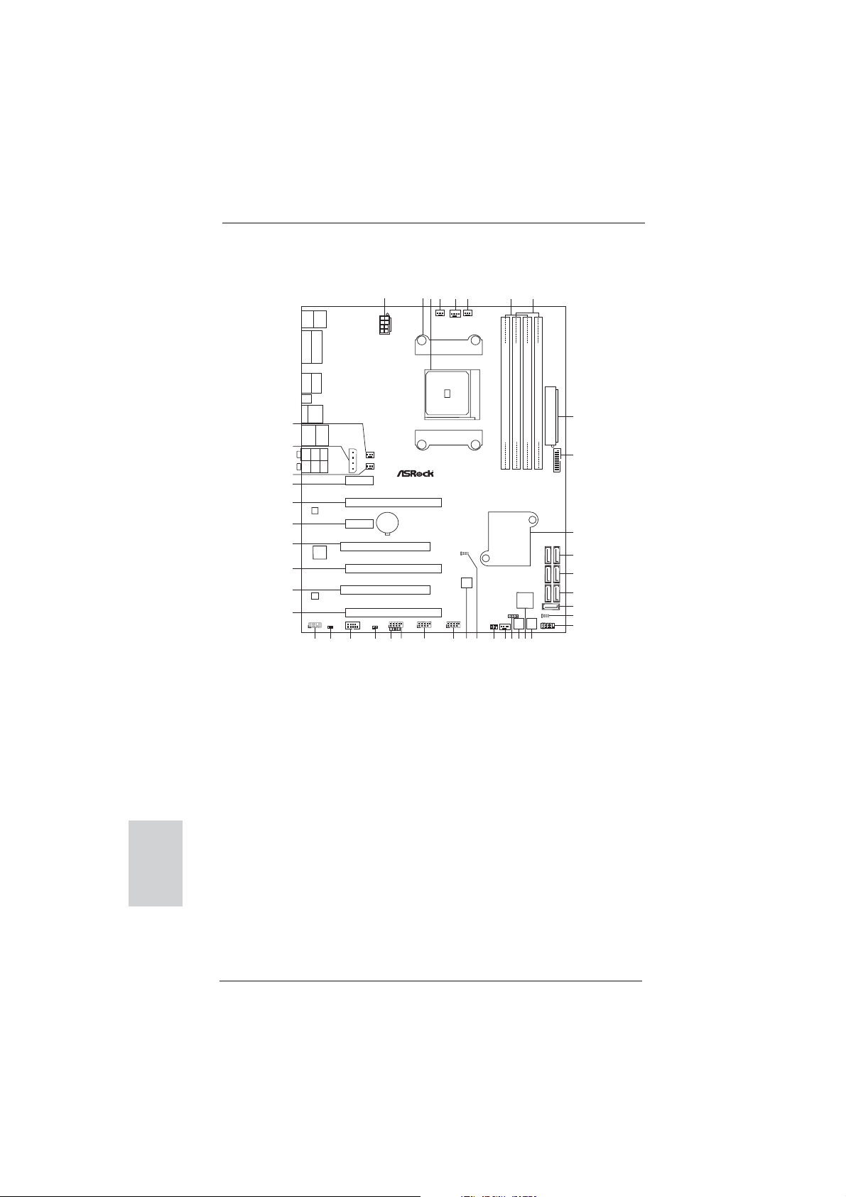
Motherboard Layout
1
Ps2
USB3.0
T:US B1
Keyboard
B:USB2
/Mouse
VGA1
DVI1
HDMI
DP_1
Clr
CMOS
eSATA
USB2.0
T:USB6
B:USB7
43
USB3.0
Top:
T:USB3
RJ-45
B:USB4
42
Top:
CTR BASS
Center:
REAR SPK
Bottom:
Optical
SPDIF
Bottom:
MIC IN
Top:
LINE IN
Center:
FRONT
41
40
39
Fast LAN
X
LAN
38
37
Super
I/O
CROSS_FIRE_PWR1
PCIE1
DX11
PCIE3
ErP/EuP Ready
ATX12V1
CHA_FAN3
CHA_FAN2
CMOS
BATTERY
PCI1
36
35
AUDIO
CODEC
34
HD_AUDIO1
HDMI_SPDIF1
1
1
32
33
PCI2
COM1
CI1
1
3031
3
2
PWR_FAN1
FM2A85X Extreme6
PCIE2
X
Fast USB
PCIE4
RoHS
PCIE5
USB_4_5
USB_2_3
1
1
1
CIR1
27
29
28
5
4
CPU_FAN1
Dual Graphics
CLRCMOS1
1
USB_0_1
1
26
6
CPU_FAN2
64Mb
BIOS
25
1 ATX 12V Power Connector (ATX12V1) 22 Chassis Fan Connector (CHA_FAN1)
2 CPU Heatsink Retention Module 23 Infrared Module Header (IR1)
3 CPU Socket 24 Clear CMOS Jumper (CLRCMOS1)
4 Power Fan Connector (PWR_FAN1) 25 SPI Flash Memory (64Mb)
5 CPU Fan Connector (CPU_FAN1) 26 USB 2.0 Header (USB_0_1)
6 CPU Fan Connector (CPU_FAN2) 27 USB 2.0 Header (USB_2_3)
7 2 x 240-pin DDR3 DIMM Slots 28 USB 2.0 Header (USB_4_5)
(Dual Channel A: DDR3_A1, DDR3_B1) 29 Consumer Infrared Module Header (CIR1)
8 2 x 240-pin DDR3 DIMM Slots 30 Chassis Intrusion Header (CI1)
(Dual Channel B: DDR3_A2, DDR3_B2) 31 COM Port Header (COM1)
9 ATX Power Connector (ATXPWR1) 32 HDMI_SPDIF Header (HDMI_SPDIF1)
10 USB 3.0 Header (USB3_5_6) 33 Front Panel Audio Header (HD_AUDIO1)
11 Southbridge Controller 34 PCI Express 2.0 x16 Slot (PCIE5)
12 SATA3 Connectors (SATA3_1_2) 35 PCI Slot (PCI2)
13 SATA3 Connectors (SATA3_3_4) 36 PCI Express 2.0 x16 Slot (PCIE4)
14 SATA3 Connectors (SATA3_7_8) 37 PCI Slot (PCI1)
15 SATA3 Connector (SATA3_5) 38 PCI Express 2.0 x1 Slot (PCIE3)
16 Power LED Header (PLED1) 39 PCI Express 2.0 x16 Slot (PCIE2)
17 System Panel Header (PANEL1) 40 PCI Express 2.0 x1 Slot (PCIE1)
18 Power Switch (PWRBTN) 41 Chassis Fan Connector (CHA_FAN2)
19 Dr. Debug (LED) 42 XFire Power Connector (CROSS_FIRE_PWR1)
20 Reset Switch (RSTBTN) 43 Chassis Fan Connector (CHA_FAN3)
21 Chassis Speaker Header (SPEAKER1)
SOCKET FM2
24
DDR3 2600+
DDR3_A1(64 bit, 240-pinmodule)
Fast RAM
X
AMD
A85X
(Hudson-D4)
Chipset
1
CHA_FAN1
IR1
1
23
22
7
8
9
ATXPWR1
DDR3_B2(64 bit, 240-pinmodule)
DDR3_A2(64 bit, 240-pinmodule)
DDR3_B1(64 bit, 240-pinmodule)
10
USB3_5_6
Front USB3.0
11
12
SATA3_1_2
13
SATA3_3_4
14
SATA3_7_8
Dr.
Debug
SPEAKER1
RESET
POWER
18
21
19
20
15
SATA3_5
PLED1
1
16
PANEL1
PLEDPWRBTN
17
1
HDLED RESET
2
ASRock FM2A85X Extreme6 Motherboard
Page 3
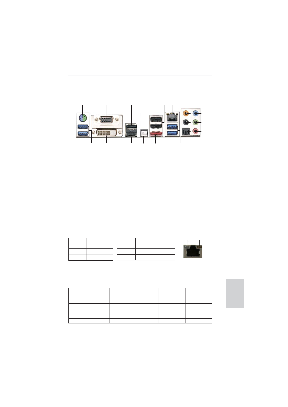
I/O Panel
5
4
9
6
10
7
11
8
12
ACT/LINK
LED
SPEED
LED
15
3
13
14
1
17
1 PS/2 Mouse/Keyboard Port (Green/Purple) *** 10 Front Speaker (Lime)
2 D-Sub Port (VGA1) 11 Microphone (Pink)
3 DisplayPort (DP_1) 12 USB 3.0 Ports (USB3_3_4)
* 4 USB 2.0 Ports (USB_6_7) **** 13 eSATA3 Connector (SATA3_6)
** 5 LAN RJ-45 Port 14 Clear CMOS Switch (CLRCBTN)
6 Central / Bass (Orange) 15 HDMI Port (HDMI1)
7 Rear Speaker (Black) 16 DVI-D Port (DVI1)
8 Optical SPDIF Out Port 17 USB 3.0 Ports (USB3_1_2)
9 Line In (Light Blue)
* It is recommended to install the USB Keyboard/Mouse cable to USB 2.0 ports (USB_7_9)
instead of USB 3.0 ports.
** There are two LED next to the LAN port. Please refer to the table below for the LAN port LED
indications.
Activity/Link LED SPEED LED
Status Description Status Description
2
16
LAN Port LED Indications
Off No Link Off 10Mbps connection
Blinking Data Activity Orange 100Mbps connection
On Link Green 1Gbps connection
LAN Port
If you use 2-channel speaker, please connect the speaker’s plug into “Front Speaker Jack”.
***
See the table below for connection details in accordance with the type of speaker you use.
TABLE for Audio Output Connection
Audio Output Channels Front Speaker Rear Speaker Central / Bass Line In or
(No. 10) (No. 7) (No. 6) Side Speaker
(No. 9)
2 V -- -- -4 V V -- -6 V V V -8 V V V V
3
ASRock FM2A85X Extreme6 Motherboard
English
Page 4
To enable Multi-Streaming function, you need to connect a front panel audio cable to the front
panel audio header. After restarting your computer, you will fi nd “Mixer” tool on your system.
Please select “Mixer ToolBox” , click “Enable playback multi-streaming”, and click “ok”.
Choose “2CH”, “4CH”, “6CH”, or “8CH” and then you are allowed to select “Realtek HDA Primary output” to use Rear Speaker, Central/Bass, and Front Speaker, or select “Realtek HDA
Audio 2nd output” to use front panel audio.
**** eSATA3 connector supports SATA Gen3 in cable 1M.
English
4
ASRock FM2A85X Extreme6 Motherboard
Page 5
1. Introduction
Thank you for purchasing ASRock FM2A85X Extreme6 motherboard, a reliable
motherboard produced under ASRock’s consistently stringent quality control. It
delivers excellent performance with robust design conforming to ASRock’s commitment to quality and endurance.
This Quick Installation Guide contains introduction of the motherboard and step-bystep installation guide. More detailed information of the motherboard can be found
in the user manual presented in the Support CD.
Because the motherboard specifi cations and the BIOS software might be
updated, the content of this manual will be subject to change without notice. In case any modifi cations of this manual occur, the updated version
will be available on ASRock website without further notice. You may fi nd
the latest VGA cards and CPU support lists on ASRock website as well.
ASRock website http://www.asrock.com
If you require technical support related to this motherboard, please visit
our website for specifi c information about the model you are using.
www.asrock.com/support/index.asp
1.1 Package Contents
ASRock FM2A85X Extreme6 Motherboard (ATX Form Factor)
ASRock FM2A85X Extreme6 Quick Installation Guide
ASRock FM2A85X Extreme6 Support CD
4 x Serial ATA (SATA) Data Cables (Optional)
1 x I/O Panel Shield
ASRock Reminds You...
To get better performance in Windows® 8 / 8 64-bit / 7 / 7 64-bit / Vista
VistaTM 64-bit, it is recommended to set the BIOS option in Storage Confi guration to AHCI mode. For the BIOS setup, please refer to the “User
Manual” in our support CD for details.
TM
ASRock FM2A85X Extreme6 Motherboard
/
English
5
Page 6
English
1.2 Specifi cations
Platform - ATX Form Factor
- Premium Gold Capacitor design (100% Japan-made
high-quality Conductive Polymer Capacitors)
CPU - Support for Socket FM2 100W processors
- Digi Power Design
- 8 + 2 Power Phase Design
- Supports AMD’s Cool ‘n’ Quiet
- UMI-Link GEN2
Chipset - AMD A85X (Hudson-D4)
Memory - Dual Channel DDR3 Memory Technology
- 4 x DDR3 DIMM slots
- Support DDR3 2600+(OC)/2400(OC)/2133(OC)/1866/1600/
1333/1066/800 non-ECC, un-buffered memory
(see CAUTION 1)
* 2600+ is only supported with two DIMMs
- Max. capacity of system memory: 64GB (see CAUTION 2)
- Supports Intel
®
Extreme Memory Profi le (XMP) 1.3 / 1.2
- Supports AMD Memory Profi le (AMP)
Expansion Slot - 3 x PCI Express 2.0 x16 slots
(PCIE2/PCIE4: single at x16 (PCIE2) / x8 (PCIE4), or dual
at x8 (PCIE2) / x8 (PCIE4) ; PCIE5: x4 mode)
- 2 x PCI Express 2.0 x1 slots
- 2 x PCI slots
- Supports AMD Quad CrossFireX
CrossFireXTM and Dual Graphics
Graphics - AMD Radeon HD 7000 graphics
- DirectX 11, Pixel Shader 5.0
- Max. shared memory 2GB
- Four VGA Output options: D-Sub, DVI-D, HDMI and
DisplayPort (see CAUTION 3)
- Supports HDMI 1.4a Technology with max. resolution up to
1920x1200 @ 60Hz
- Supports Dual-link DVI with max. resolution up to
2560x1600 @ 75Hz
- Supports D-Sub with max. resolution up to 1920x1600 @
60Hz
- Supports DisplayPort 1.2 with max. resolution up to
4096x2160 @ 30Hz
- Supports DP++
TM
Technology
TM
, 3-Way CrossFireXTM,
6
ASRock FM2A85X Extreme6 Motherboard
Page 7
- Supports Multi-Streaming
- Supports Auto Lip Sync, Deep Color (12bpc), xvYCC and
HBR (High Bit Rate Audio) with HDMI (Compliant HDMI
monitor is required) (see CAUTION 4)
- Supports Blu-ray Stereoscopic 3D with HDMI 1.4a
- Supports AMD Steady Video
TM
2.0: New video post
processing capability for automatic jutter reduction on home/
online video
- Supports HDCP function with DVI, HDMI and DisplayPort
ports
- Supports Full HD 1080p Blu-ray (BD) / HD-DVD playback
with DVI, HDMI and DisplayPort ports
Audio - 7.1 CH HD Audio with Content Protection
(Realtek ALC898 Audio Codec)
- Premium Blu-ray audio support
- Supports THX TruStudio
TM
LAN - PCIE x1 Gigabit LAN 10/100/1000 Mb/s
- Realtek RTL8111E
- Supports Wake-On-LAN
- Supports LAN Cable Detection
- Supports Energy Effi cient Ethernet 802.3az
- Supports PXE
Rear Panel I/O I/O Panel
- 1 x PS/2 Mouse/Keyboard Port
- 1 x D-Sub Port
- 1 x DVI-D Port
- 1 x HDMI Port
- 1 x DisplayPort
- 1 x Optical SPDIF Out Port
- 2 x Ready-to-Use USB 2.0 Ports
- 1 x eSATA3 Connector
- 4 x Ready-to-Use USB 3.0 Ports
- 1 x RJ-45 LAN Port with LED (ACT/LINK LED and SPEED
LED)
- 1 x Clear CMOS Switch with LED
- HD Audio Jack: Rear Speaker/Central/Bass/Line in/Front
Speaker/Microphone
SATA 3 - 7 x SATA3 6.0 Gb/s connectors, support RAID (RAID 0,
RAID 1, RAID 5 and RAID 10), NCQ, AHCI and “Hot Plug”
functions
USB 3.0 - 2 x Rear USB 3.0 ports by AMD A85X (Hudson-D4), support
USB 1.1/2.0/3.0 up to 5Gb/s
ASRock FM2A85X Extreme6 Motherboard
English
7
Page 8
English
- 2 x Rear USB 3.0 ports by ASMedia ASM1042, support USB
1.1/2.0/3.0 up to 5Gb/s
- 1 x Front USB 3.0 header (supports 2 USB 3.0 ports) by
AMD A85X (Hudson-D4), supports USB 1.1/2.0/3.0 up to
5Gb/s
Connector - 7 x SATA3 6.0Gb/s connectors
- 1 x IR header
- 1 x CIR header
- 1 x COM port header
- 1 x HDMI_SPDIF header
- 1 x Power LED header
- 1 x Chassis Intrusion header
- 2 x CPU Fan connectors (1 x 4-pin, 1 x 3-pin)
- 3 x Chassis Fan connectors (1 x 4-pin, 2 x 3-pin)
- 1 x Power Fan connector (3-pin)
- 24 pin ATX power connector
- 8 pin 12V power connector
- XFire power connector
- Front panel audio connector
- 3 x USB 2.0 headers (support 6 USB 2.0 ports)
- 1 x USB 3.0 header (supports 2 USB 3.0 ports)
- 1 x Dr. Debug (7-Segment Debug LED)
- 1 x Power Switch with LED
- 1 x Reset Switch with LED
BIOS Feature - 64Mb AMI UEFI Legal BIOS with GUI support
- Supports “Plug and Play”
- ACPI 1.1 Compliance Wake Up Events
- Supports jumperfree
- SMBIOS 2.3.1 Support
- DRAM, APU PCIE VDDP, CPU and CPU NB/GFX Voltage
Multi-adjustment
Support CD - Drivers, Utilities, AntiVirus Software (Trial Version),
CyberLink MediaEspresso 6.5 Trial, Google Chrome
Browser and Toolbar
Hardware - CPU Temperature Sensing
Monitor - Chassis Temperature Sensing
- CPU/Chassis/Power Fan Tachometer
- CPU Quiet Fan
- CPU/Chassis Fan Multi-Speed Control
- CASE OPEN detection
- Voltage Monitoring: +12V, +5V, +3.3V, Vcore
8
ASRock FM2A85X Extreme6 Motherboard
Page 9

OS - Microsoft® Windows® 8 / 8 64-bit / 7 / 7 64-bit / Vista
TM
/
VistaTM 64-bit compliant
Certifi cations - FCC, CE, WHQL
- ErP/EuP Ready (ErP/EuP ready power supply is required)
* For detailed product information, please visit our website: http://www.asrock.com
WARNING
Please realize that there is a certain risk involved with overclocking,
including adjusting the setting in the BIOS, applying Untied Overclocking
Technology, or using third-party overclocking tools. Overclocking may
affect your system’s stability, or even cause damage to the components
and devices of your system. It should be done at your own risk and
expense. We are not responsible for possible damage caused by
overclocking.
CAUTION!
1. Whether 2600/2400/2133/1866/1600MHz memory speed is
supported depends on the CPU you adopt. If you want to adopt
DDR3 2600/2400/2133/1866/1600 memory module on this
motherboard, please refer to the memory support list on our
website for the compatible memory modules.
ASRock website http://www.asrock.com
2. Due to the operating system limitation, the actual memory size
may be less than 4GB for the reservation for system usage under Windows
bit CPU, there is no such limitation. You can use ASRock XFast
RAM to utilize the memory that Windows® cannot use.
3. You can choose to use three of the four monitors only. D-Sub,
DVI-D, HDMI and DisplayPort monitors cannot be enabled at
the same time. Besides, with the DVI-to-HDMI adapter, the DVID port can support the same features as HDMIport.
4. xvYCC and Deep Color are only supported under Windows
64-bit / 8 / 7 64-bit / 7. Deep Color mode will be enabled only
if the display supports 12bpc in EDID. HBR is supported under
Windows® 8 64-bit / 8 / 7 64-bit / 7 / VistaTM 64-bit / VistaTM.
®
8 / 7 / VistaTM. For Windows® 64-bit OS with 64-
®
8
English
ASRock FM2A85X Extreme6 Motherboard
9
Page 10

1.3 Unique Features
ASRock Extreme Tuning Utility (AXTU)
ASRock Extreme Tuning Utility (AXTU) is an all-in-one tool to
ne-tune different system functions in a user-friendly interface,
which includes Hardware Monitor, Fan Control, Overclocking,
OC DNA, IES and XFast RAM. In Hardware Monitor, it shows
the major readings of your system. In Fan Control, it shows the
fan speed and temperature for you to adjust. In Overclocking,
you are allowed to overclock CPU frequency for optimal system
performance. In OC DNA, you can save your OC settings as
a profi le and share it with your friends. Your friends then can
load the OC profi le to their own system to get the same OC set-
tings. In IES (Intelligent Energy Saver), the voltage regulator
can reduce the number of output phases to improve effi ciency
when the CPU cores are idle without sacrifi cing computing per-
formance. In
cannot be used under Windows® OS 32-bit CPU.
ASRock Instant Boot
ASRock Instant Boot allows you to turn on your PC in just a few
seconds, provides a much more effi cient way to save energy,
time, money, and improves system running speed for your system. It leverages the S3 and S4 ACPI features which normally
enable the Sleep/Standby and Hibernation modes in Windows
to shorten boot up time. By calling S3 and S4 at specifi c timing
during the shutdown and startup process, Instant Boot allows
you to enter your Windows
XFast RAM, it fully utilizes the memory space that
®
desktop in a few seconds.
®
English
10
ASRock Instant Flash
ASRock Instant Flash is a BIOS fl ash utility embedded in Flash
ROM. This convenient BIOS update tool allows you to update
system BIOS without entering operating systems fi rst like MS-
DOS or Windows
®
. With this utility, you can press the <F6> key
during the POST or the <F2> key to enter into the BIOS setup
menu to access ASRock Instant Flash. Just launch this tool and
save the new BIOS fi le to your USB fl ash drive, fl oppy disk or
hard drive, then you can update your BIOS only in a few clicks
without preparing an additional fl oppy diskette or other compli-
cated fl ash utility. Please be noted that the USB fl ash drive or
hard drive must use FAT32/16/12 fi le system.
ASRock FM2A85X Extreme6 Motherboard
Page 11

ASRock APP Charger
If you desire a faster, less restricted way of charging your
Apple devices, such as iPhone/iPad/iPod Touch, ASRock has
prepared a wonderful solution for you - ASRock APP Charger.
Simply install the APP Charger driver, it makes your iPhone
charge much quickly from your computer and up to 40% faster
than before. ASRock APP Charger allows you to quickly charge
many Apple devices simultaneously and even supports continuous charging when your PC enters into Standby mode (S1),
Suspend to RAM (S3), hibernation mode (S4) or power off (S5).
With APP Charger driver installed, you can easily enjoy the marvelous charging experience.
ASRock XFast USB
ASRock XFast USB can boost USB storage device perfor-
mance. The performance may depend on the properties of the
device.
ASRock XFast LAN
ASRock XFast LAN provides a faster internet access, which
includes the benefits listed below. LAN Application Prioritization: You can confi gure your application’s priority ideally and/or
add new programs. Lower Latency in Game: After setting online
game’s priority higher, it can lower the latency in games. Traffi c
Shaping: You can watch Youtube HD videos and download simultaneously. Real-Time Analysis of Your Data: With the status
window, you can easily recognize which data streams you are
transferring currently.
ASRock XFast RAM
ASRock XFast RAM is a new function that is included into ASRock Extreme Tuning Utility (AXTU). It fully utilizes the memory
space that cannot be used under Windows® OS 32-bit CPU.
ASRock XFast RAM shortens the loading time of previously
visited websites, making web surfing faster than ever. And it
also boosts the speed of Adobe Photoshop 5 times faster. Another advantage of ASRock XFast RAM is that it reduces the
frequency of accessing your SSDs or HDDs in order to extend
their lifespan.
ASRock FM2A85X Extreme6 Motherboard
English
11
Page 12

ASRock Crashless BIOS
ASRock Crashless BIOS allows users to update their BIOS
without fear of failing. If power loss occurs during the BIOS update process, ASRock Crashless BIOS will automatically fi nish
the BIOS update procedure after regaining power. Please note
that BIOS fi les need to be placed in the root directory of your
USB disk. Only USB2.0 ports support this feature.
ASRock OMG (Online Management Guard)
Administrators are able to establish an internet curfew or restrict
internet access at specifi ed times via OMG. You may schedule
the starting and ending hours of internet access granted to other
users. In order to prevent users from bypassing OMG, guest
accounts without permission to modify the system time are required.
ASRock Internet Flash
ASRock Internet Flash searches for available UEFI firmware
updates from our servers. In other words, the system can autodetect the latest UEFI from our servers and fl ash them without
entering Windows
®
OS. Please note that you must be running
on a DHCP confi gured computer in order to enable this function.
ASRock UEFI System Browser
ASRock UEFI system browser is a useful tool included in
graphical UEFI. It can detect the devices and configurations
that users are currently using in their PC. With the UEFI system
browser, you can easily examine the current system confi gura-
tion in UEFI setup.
English
ASRock Dehumidifi er Function
Users may prevent motherboard damages due to dampness by
enabling “Dehumidifi er Function”. When enabling Dehumidifi er
Function, the computer will power on automatically to dehumidify the system after entering S4/S5 state.
ASRock Easy RAID Installer
ASRock Easy RAID Installer can help you to copy the RAID
driver from a support CD to your USB storage device. After
copying the RAID driver to your USB storage device, please
change “SATA Mode” to “RAID”, then you can start installing the
OS in RAID mode.
12
ASRock FM2A85X Extreme6 Motherboard
Page 13

ASRock Interactive UEFI
ASRock Interactive UEFI is a blend of system configuration
tools, cool sound effects and stunning visuals. The unprecedented UEFI provides a more attractive interface and brings a
lot more amusing.
ASRock Fast Boot
With ASRock’s exclusive Fast Boot technology, it takes less
than 1.5 seconds to logon to Windows
®
8 from a cold boot. No
more waiting! The speedy boot will completely change your user
experience and behavior.
ASRock X-Boost
Brilliantly designed for combo overclocking, ASRock X-Boost
Technology is able to unleash the hidden power of your CPUs.
Simply press “X” when turning on the PC, X-Boost will automatically overclock the relative components to get up to 15.77%
performance boost! With the smart X-Boost, overclocking CPU
can become a near one-button process.
ASRock Restart to UEFI
Windows
®
8 brings the ultimate boot up experience. The lightning boot up speed makes it hard to access the UEFI setup. ASRock Restart to UEFI technology is designed for those requiring
frequent UEFI access. It is included in ASRock’s exclusive allin-one AXTU tuning program that allows users to easily enter
the UEFI automatically when turning on the PC next time. Just
simply enable this function; the PC will be assured to access the
UEFI directly in the very beginning.
Lucid Virtu Universal MVP
VIRTU Universal MVP includes the base features of Virtu
Universal technology, which virtualizes integrated GPU and
discrete GPU for best of breed functionality. It also features Virtual Vsync™ for no-compromise visual quality. With the added
benefi ts of HyperFormance technology, VIRTU Universal MVP
improves game performance by intelligently reducing redundant
rendering tasks in the fl ow between the CPU, GPU and the dis-
play.
ASRock FM2A85X Extreme6 Motherboard
English
13
Page 14
2. Installation
This is an ATX form factor motherboard. Before you install the motherboard, study
the confi guration of your chassis to ensure that the motherboard fi ts into it.
Pre-installation Precautions
Take note of the following precautions before you install motherboard
components or change any motherboard settings.
Before you install or remove any component, ensure that the
power is switched off or the power cord is detached from the
power supply. Failure to do so may cause severe damage to the
motherboard, peripherals, and/or components.
1. Unplug the power cord from the wall socket before touching any
component.
2. To avoid damaging the motherboard components due to static electricity, NEVER place your motherboard directly on the carpet or the
like. Also remember to use a grounded wrist strap or touch a safety
grounded object before you handle components.
3. Hold components by the edges and do not touch the ICs.
4. Whenever you uninstall any component, place it on a grounded antistatic pad or in the bag that comes with the component.
5. When placing screws into the screw holes to secure the motherboard to the chassis, please do not over-tighten the screws! Doing
so may damage the motherboard.
English
14
ASRock FM2A85X Extreme6 Motherboard
Page 15
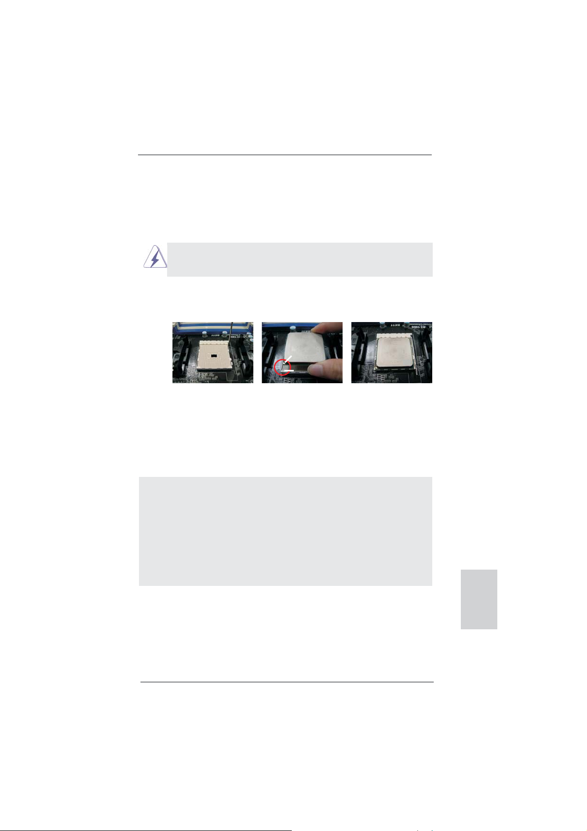
2.1 CPU Installation
Step 1. Unlock the socket by lifting the lever up to a 90
o
angle.
Step 2. Position the CPU directly above the socket such that the CPU corner with
the golden triangle matches the socket corner with a small triangle.
Step 3. Carefully insert the CPU into the socket until it fi ts in place.
The CPU fi ts only in one correct orientation. DO NOT force the CPU
into the socket to avoid bending of the pins.
Step 4. When the CPU is in place, press it fi rmly on the socket while you push
down the socket lever to secure the CPU. The lever clicks on the side tab
to indicate that it is locked.
Lever 90° Up
CPU Golden Triangle
Socket Corner Small
Triangle
STEP 1:
Lift Up The Socket Lever
STEP 2 / STEP 3:
Match The CPU Golden Triangle
To The Socket Corner Small
Triangle
STEP 4:
Push Down And Lock
The Socket Lever
2.2 Installation of CPU Fan and Heatsink
After you install the CPU into this motherboard, it is necessary to install a
larger heatsink and cooling fan to dissipate heat. You also need to spray
thermal grease between the CPU and the heatsink to improve heat dissipation. Make sure that the CPU and the heatsink are securely fastened
and in good contact with each other. Then connect the CPU fan to the
CPU FAN connector (CPU_FAN1, see Page 2, No. 5 or CPU_FAN2, see
Page 2, No. 6). For proper installation, please kindly refer to the instruction manuals of the CPU fan and the heatsink.
English
ASRock FM2A85X Extreme6 Motherboard
15
Page 16
English
2.3 Installation of Memory Modules (DIMM)
This motherboard provides four 240-pin DDR3 (Double Data Rate 3) DIMM
slots, and supports Dual Channel Memory Technology. For dual channel confi guration, you always need to install identical (the same brand, speed, size
and chip-type) DDR3 DIMM pair in the slots of the same color. In other words,
you have to install identical DDR3 DIMM pair in Dual Channel A (DDR3_A1
and DDR3_B1; see p.2 No.7) or identical DDR3 DIMM pair in Dual Channel
B (DDR3_A2 and DDR3_B2; see p.2 No.8), so that Dual Channel Memory
Technology can be activated. This motherboard also allows you to install four
DDR3 DIMMs for dual channel confi guration, and please install identical DDR3
DIMMs in all four slots. You may refer to the Dual Channel Memory Confi gura-
tion Table below.
Dual Channel Memory Confi gurations
DDR3_A1 DDR3_A2 DDR3_B1 DDR3_B2
(1) Populated - Populated (2) - Populated - Populated
(3)* Populated Populated Populated Populated
For the confi guration (3), please install identical DDR3 DIMMs in all four
*
slots.
1. If you want to install two memory modules, for optimal compatibility
and reliability, it is recommended to install them in the slots: DDR3_
A1 and DDR3_B1, or DDR3_A2 and DDR3_B2.
2. If only one memory module or three memory modules are installed
in the DDR3 DIMM slots on this motherboard, it is unable to activate
the Dual Channel Memory Technology.
3. If a pair of memory modules is NOT installed in the same Dual
Channel, for example, installing a pair of memory modules in
DDR3_A1 and DDR3_A2, it is unable to activate the Dual Channel
Memory Technology .
4. It is not allowed to install a DDR or DDR2 memory module into
DDR3 slot; otherwise, this motherboard and DIMM may be damaged.
5. If you adopt DDR3 2600/2400/2133/1866/1600 memory modules
on this motherboard, it is recommended to install them on DDR3_
A2 and DDR3_B2 slots.
16
ASRock FM2A85X Extreme6 Motherboard
Page 17
Installing a DIMM
Please make sure to disconnect power supply before adding or
removing DIMMs or the system components.
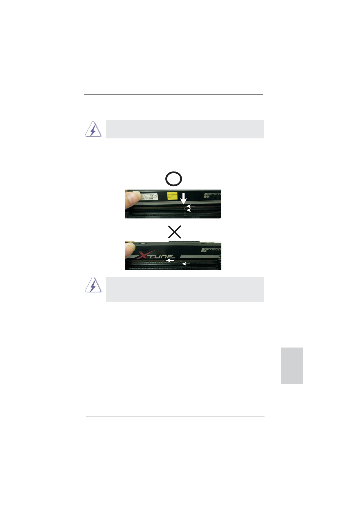
Step 1. Unlock a DIMM slot by pressing the retaining clips outward.
Step 2. Align a DIMM on the slot such that the notch on the DIMM matches the
break on the slot.
notch
break
notch
break
The DIMM only fi ts in one correct orientation. It will cause permanent
damage to the motherboard and the DIMM if you force the DIMM into
the slot at incorrect orientation.
Step 3. Firmly insert the DIMM into the slot until the retaining clips at both ends
fully snap back in place and the DIMM is properly seated.
ASRock FM2A85X Extreme6 Motherboard
English
17
Page 18
2.4 Expansion Slots (PCI and PCI Express Slots)
There are 2 PCI slots and 5 PCI Express slots on this motherboard.
PCI Slots: PCI slots are used to install expansion cards that have the 32-bit PCI
interface.
PCIE Slots:
PCIE1 / PCIE3 (PCIE x1 slot) is used for PCI Express cards with x1
lane width cards, such as Gigabit LAN card and SATA2 card.
PCIE2 / PCIE4 (PCIE x16 slot) is used for PCI Express x16 lane width
graphics cards, or used to install PCI Express graphics cards to support
CrossFireX
PCIE5 (PCIE x16 slot) is used for PCI Express x4 lane width cards, or
used to install PCI Express graphics cards to support 3-Way
CrossFireX
1. In single VGA card mode, it is recommended to install a PCI Ex-
2. In CrossFireXTM mode, please install PCI Express x16 graphics
3. In 3-Way CrossFireX
4. Please connect a chassis fan to motherboard chassis fan connec-
5. When PCIE2 slot is occupied, the DisplayPort cannot be used.
TM
function.
TM
function.
press x16 graphics card on PCIE2 slot.
cards on PCIE2 and PCIE4 slots. Therefore, both these two slots
will work at x8 bandwidth.
graphics cards in PCIE2, PCIE4 and PCIE5 slots. PCIE2 and
PCIE4 will work at x8 bandwidth, while PCIE5 works at x4 bandwidth.
tor (CHA_FAN1, CHA_FAN2 or CHA_FAN3) when using multiple
graphics cards for better thermal environment.
TM
mode, please install the PCI Express x16
English
Installing an expansion card
Step 1. Before installing the expansion card, please make sure that the power
supply is switched off or the power cord is unplugged. Please read the
documentation of the expansion card and make necessary hardware
settings for the card before you start the installation.
Step 2. Remove the system unit cover (if your motherboard is already installed
in a chassis).
Step 3. Remove the bracket facing the slot that you intend to use. Keep the
screws for later use.
Step 4. Align the card connector with the slot and press fi rmly until the card is
completely seated on the slot.
Step 5. Fasten the card to the chassis with screws.
Step 6. Replace the system cover.
18
ASRock FM2A85X Extreme6 Motherboard
Page 19
2.5 CrossFireXTM, 3-Way CrossFireXTM and Quad
CrossFireX
This motherboard supports CrossFireXTM, 3-way CrossFireX
CrossFireX
means available of combining multiple high performance Graphics Processing
Units (GPU) in a single PC. Combining a range of different operating modes with
intelligent software design and an innovative interconnect mechanism, CrossFireX
enables the highest possible level of performance and image quality in any 3D
application. Please check AMD website for ATITM CrossFireXTM driver updates.
1. If a customer incorrectly confi gures their system they will not see the
performance benefi ts of CrossFireXTM. All three CrossFireXTM components, a
CrossFireXTM Ready graphics card, a CrossFireXTM Ready motherboard and a
CrossFireXTM Edition co-processor graphics card, must be installed correctly to
benefi t from the CrossFireX
2. If you pair a 12-pipe CrossFireXTM Edition card with a 16-pipe card, both cards
will operate as 12-pipe cards while in CrossFireXTM mode.
TM
feature. CrossFireXTM technology offers the most advantageous
TM
Operation Guide
TM
multi-GPU platform.
TM
and Quad
TM
2.5.1 Graphics Card Setup
2.5.1.1 Installing Two CrossFireX
Different CrossFireXTM cards may require different methods to enable CrossFireXTM
feature. For other CrossFireXTM cards that AMD has released or will release in the
future, please refer to AMD graphics card manuals for detailed installation guide.
TM
-Ready Graphics Cards
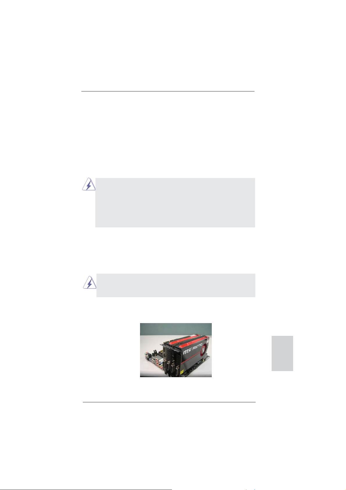
Step 1. Insert one Radeon graphics card into PCIE2 slot and the other Radeon
graphics card to PCIE4 slot. Make sure that the cards are properly seated
on the slots.
ASRock FM2A85X Extreme6 Motherboard
English
19
Page 20

Step 2. Connect two Radeon graphics cards by installing CrossFire Bridge on
CrossFire Bridge Interconnects on the top of Radeon graphics cards.
(CrossFire Bridge is provided with the graphics card you purchase, not
bundled with this motherboard. Please refer to your graphics card vendor
for details.)
CrossFire Bridge
or
Step 3. Connect the DVI monitor cable to the DVI connector on the Radeon
graphics card on PCIE2 slot. (You may use the DVI to D-Sub adapter to
convert the DVI connector to D-Sub interface, and then connect the D-Sub
monitor cable to the DVI to D-Sub adapter.)
English
20
ASRock FM2A85X Extreme6 Motherboard
Page 21

2.5.1.2 Installing Three CrossFireXTM-Ready Graphics Cards
Step 1. Install the identical 3-Way CrossFireXTM-ready graphics cards that are
AMD certifi ed because different types of graphics cards will not work to-
gether properly. (Even the GPU chips version shall be the same.) Insert
one graphics card into PCIE2 slot, another graphics card to PCIE4 slot,
and the other graphics card to PCIE5 slot. Make sure that the cards are
properly seated on the slots.
Step 2. Use one CrossFire
and PCIE4 slots, and use the other CrossFireTM Bridge to connect Radeon
graphics cards on PCIE4 and PCIE5 slots. (CrossFireTM Bridge is provided
with the graphics card you purchase, not bundled with this motherboard.
Please refer to your graphics card vendor for details.)
Step 3. Connect the DVI monitor cable to the DVI connector on the Radeon graph-
ics card on PCIE2 slot. (You may use the DVI to D-Sub adapter to convert
the DVI connector to D-Sub interface, and then connect the D-Sub monitor
cable to the DVI to D-Sub adapter.)
TM
Bridge to connect Radeon graphics cards on PCIE2
CrossFireTM Bridge
English
ASRock FM2A85X Extreme6 Motherboard
21
Page 22
2.5.2 Driver Installation and Setup
Step 1. Power on your computer and boot into OS.
Step 2. Remove the ATITM driver if you have any VGA driver installed in your
system.
The Catalyst Uninstaller is an optional download. We recommend using this
utility to uninstall any previously installed Catalyst drivers prior to installation.
Please check AMD website for ATI
Step 3. Install the required drivers to your system.
For Windows® 8 / 7 / VistaTM OS:
Install the CATALYST Control Center. Please check AMD website for de-
tails.
Step 4. Restart your computer.
Step 5. Install the VGA card drivers to your system, and restart your computer.
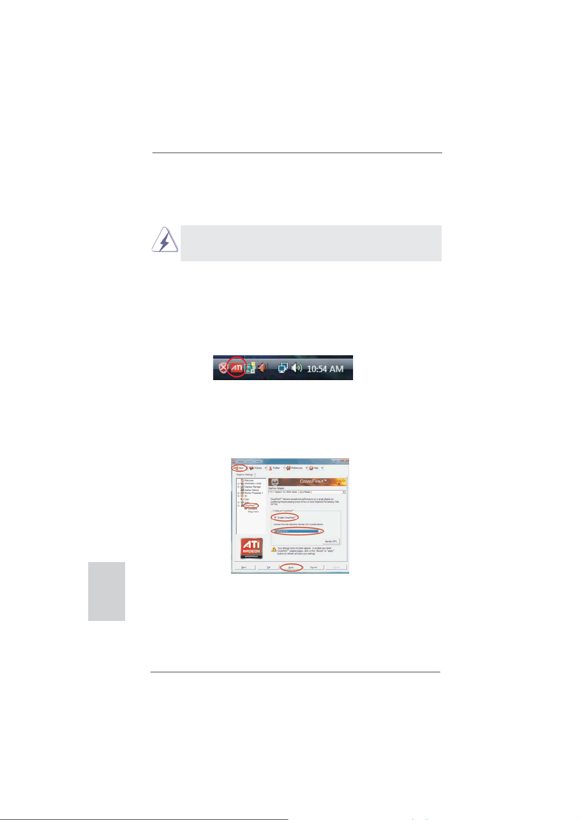
Then you will fi nd “ATI Catalyst Control Center” on your Windows
ATI Catalyst Control Center
TM
driver updates.
®
taskbar.
English
Step 6. Double-click “ATI Catalyst Control Center”. Click “View”, select “CrossFi-
TM
reX
”, and then check the item “Enable CrossFireXTM”. Select “2 GPUs”
and click “Apply” (if you install two Radeon graphics cards). Select “3
GPUs” and click “OK” (if you install three Radeon graphics cards).
22
ASRock FM2A85X Extreme6 Motherboard
Page 23
Although you have selected the option “Enable CrossFireTM”, the CrossFireXTM
function may not work actually. Your computer will automatically reboot. After
restarting your computer, please confi rm whether the option “Enable
CrossFire
select it again, and then you are able to enjoy the benefi t of CrossFireX
TM
” in “ATI Catalyst Control Center” is selected or not; if not, please
TM
feature.
Step 7. You can freely enjoy the benefi t of CrossFireXTM, 3-Way CrossFireXTM or
Quad CrossFireX
* CrossFireXTM appearing here is a registered trademark of ATITM Technologies Inc., and is
used only for identifi cation or explanation and to the owners’ benefi t, without intent to infringe.
* For further information of ATI
updates and details.
TM
feature.
TM
CrossFireXTM technology, please check AMD website for
ASRock FM2A85X Extreme6 Motherboard
English
23
Page 24
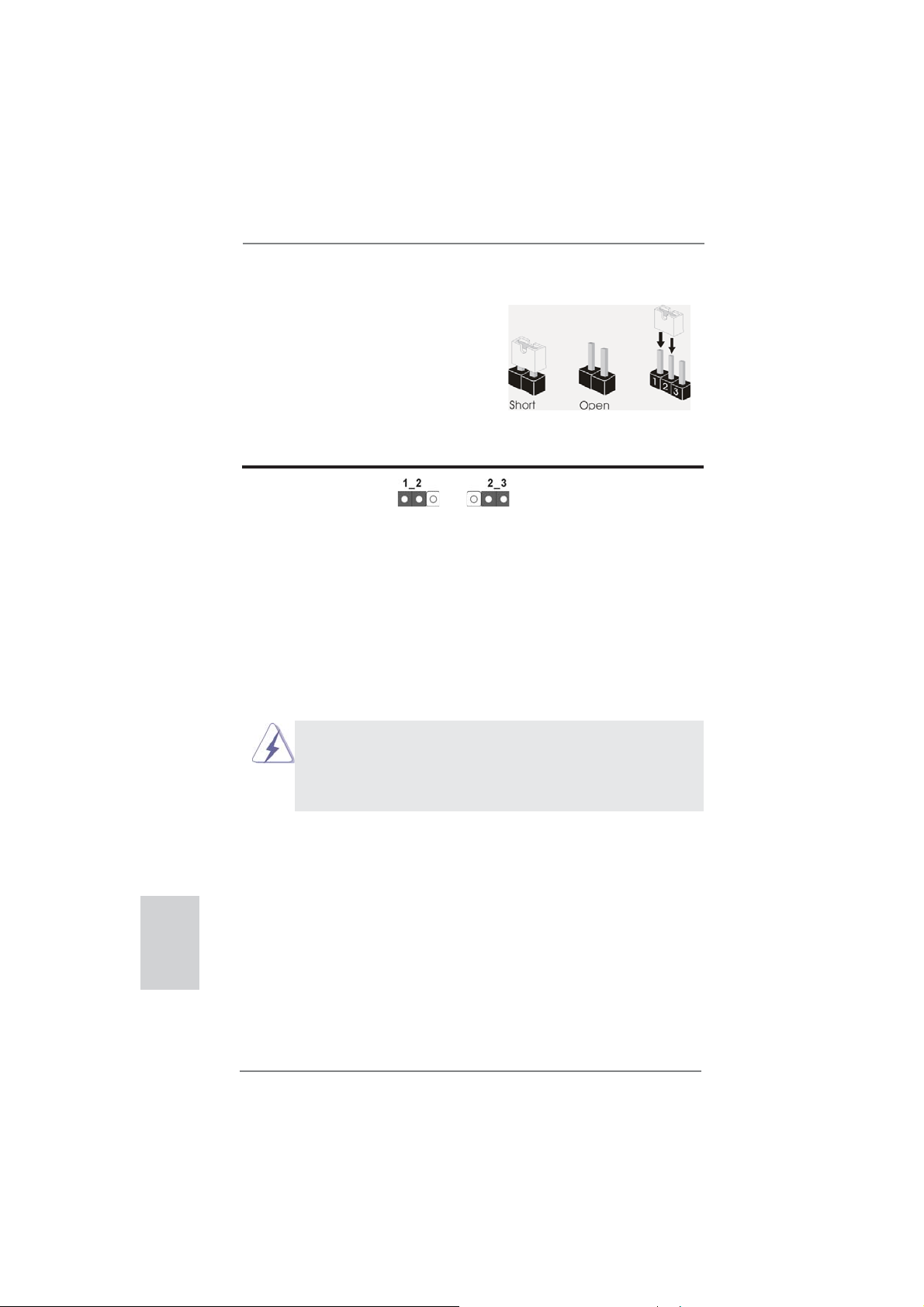
2.6 Jumpers Setup
The illustration shows how jumpers are
setup. When the jumper cap is placed on
pins, the jumper is “Short”. If no jumper cap
is placed on pins, the jumper is “Open”. The
illustration shows a 3-pin jumper whose
pin1 and pin2 are “Short” when jumper cap
is placed on these 2 pins.
Jumper Setting Description
Clear CMOS Jumper
(CLRCMOS1)
(see p.2, No. 24)
Note: CLRCMOS1 allows you to clear the data in CMOS. To clear and reset the
system parameters to default setup, please turn off the computer and unplug
the power cord from the power supply. After waiting for 15 seconds, use a
jumper cap to short pin2 and pin3 on CLRCMOS1 for 5 seconds. However,
please do not clear the CMOS right after you update the BIOS. If you need
to clear the CMOS when you just fi nish updating the BIOS, you must boot
up the system fi rst, and then shut it down before you do the clear-CMOS ac-
tion. Please be noted that the password, date, time, user default profi le, 1394
GUID and MAC address will be cleared only if the CMOS battery is removed.
1. The Clear CMOS Switch has the same function as the Clear CMOS
jumper.
2.
If you clear the CMOS, the case open may be detected. Please adjust
the BIOS option “Clear Status” to clear the record of previous chassis
intrusion status.
Clear CMOSDefault
English
24
ASRock FM2A85X Extreme6 Motherboard
Page 25
2.7 Onboard Headers and Connectors
Onboard headers and connectors are NOT jumpers. Do NOT place
jumper caps over these headers and connectors. Placing jumper caps
over the headers and connectors will cause permanent damage of the
motherboard!
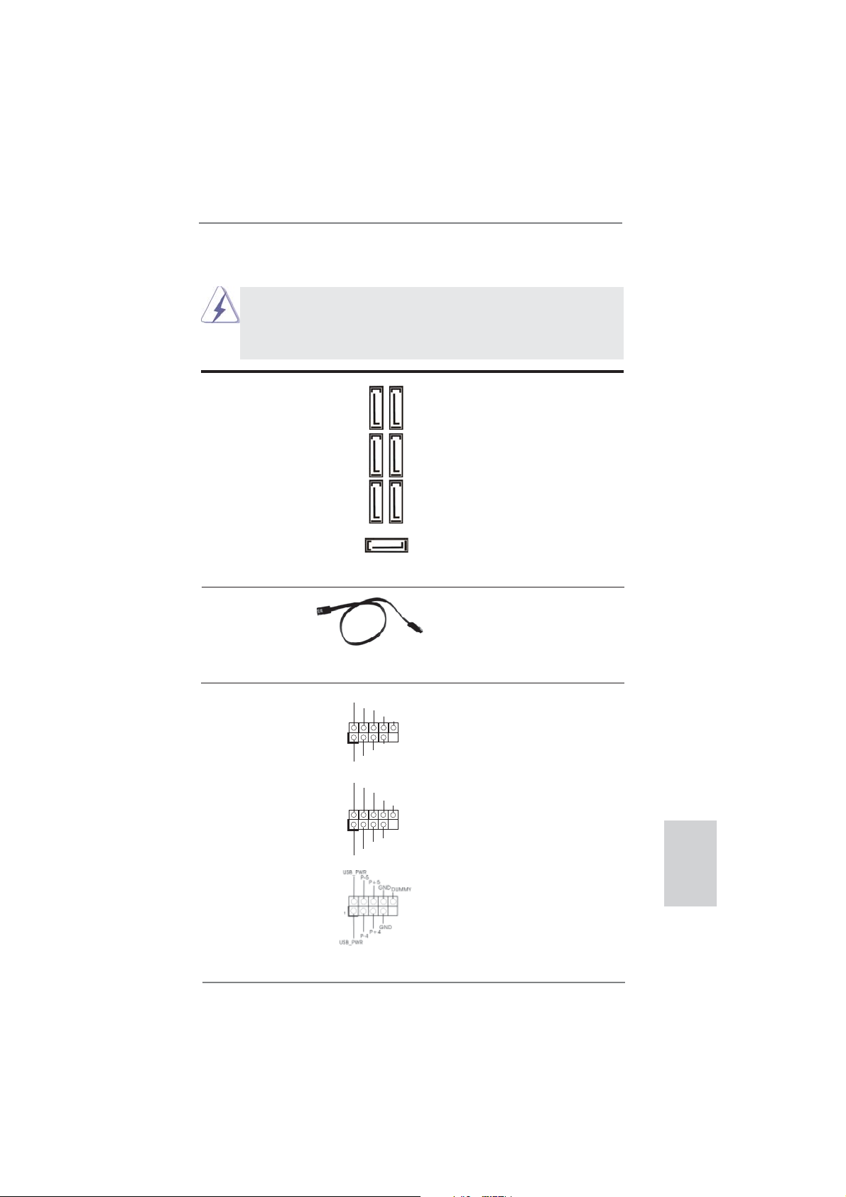
Serial ATA3 Connectors These seven Serial ATA3
(SATA3_1_2: see p.2, No. 12)
(SATA3_3_4: see p.2, No. 13)
(SATA3_7_8: see p.2, No. 14)
(SATA3_5: see p.2, No. 15)
6.0 Gb/s data transfer rate.
(SATA3) connectors support
SATA data cables for internal
storage devices. The current
SATA3 interface allows up to
SATA3_8 SATA3_4 SATA3_2
SATA3_5
SATA3_7 SATA3_3 SATA3_1
Serial ATA (SATA) Either end of the SATA data
Data Cable cable can be connected to the
(Optional)
SATA3 hard disk or the SATA3
connector on this motherboard.
USB 2.0 Headers Besides two default USB 2.0
(9-pin USB_0_1)
(see p.2 No. 26)
ports on the I/O panel, there
are three USB 2.0 headers on
this motherboard. Each USB 2.0
header can support two USB
(9-pin USB_2_3)
(see p.2 No. 27)
(9-pin USB_4_5)
(see p.2 No. 28)
2.0 ports.
USB_PWR
1
USB_PWR
USB_PWR
1
USB_PWR
P-1
P+1
GND
DUMMY
GND
P+0
P-0
P-3
P+3
GND
DUMMY
GND
P+2
P-2
English
ASRock FM2A85X Extreme6 Motherboard
25
Page 26
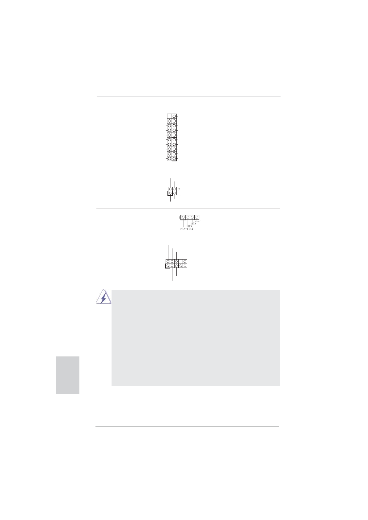
USB 3.0 Header Besides four default USB 3.0
(19-pin USB3_5_6)
(see p.2, No. 10)
ports on the I/O panel, there is
one USB 3.0 header on this
motherboard. This USB 3.0
header can support two USB 3.0
ports.
Vbus
IntA_P5_SSRX-
IntA_P5_SSRX+
GND
IntA_P5_SSTX-
IntA_P5_SSTX+
GND
IntA_P5_D-
IntA_P5_D+
VbusVbus
IntA_P6_SSRX-
IntA_P6_SSRX+
GND
IntA_P6_SSTX-
IntA_P6_SSTX+
GND
IntA_P6_D-
IntA_P6_D+
DUMMY
English
Infrared Module Header This header supports an
(5-pin IR1)
optional wireless transmitting
(see p.2 No. 23)
and receiving infrared module.
IRTX
+5VSB
DUMMY
1
GND
IRRX
Consumer Infrared Module Header This header can be used to
(4-pin CIR1)
(see p.2 No. 29)
Front Panel Audio Header This is an interface for the front
(9-pin HD_AUDIO1)
(see p.2 No. 33)
control of audio devices.
connect the remote
controller receiver.
GND
PRESENCE#
panel audio cable that allows
convenient connection and
1. High Defi nition Audio supports Jack Sensing, but the panel wire on
the chassis must support HDA to function correctly. Please follow the
instruction in our manual and chassis manual to install your system.
2. If you use AC’97 audio panel, please install it to the front panel audio
header as below:
A. Connect Mic_IN (MIC) to MIC2_L.
B. Connect Audio_R (RIN) to OUT2_R and Audio_L (LIN) to OUT2_L.
C. Connect Ground (GND) to Ground (GND).
D. MIC_RET and OUT_RET are for HD audio panel only. You don’t
need to connect them for AC’97 audio panel.
E. To activate the front mic.
For Windows
Go to the "FrontMic" Tab in the Realtek Control panel. Adjust
“Recording Volume”.
MIC_RET
OUT_RET
1
®
8 / 8 64-bit / 7 / 7 64-bit / VistaTM / VistaTM 64-bit OS:
MIC2_R
MIC2_L
J_SENSE
OUT2_R
OUT2_L
26
ASRock FM2A85X Extreme6 Motherboard
Page 27
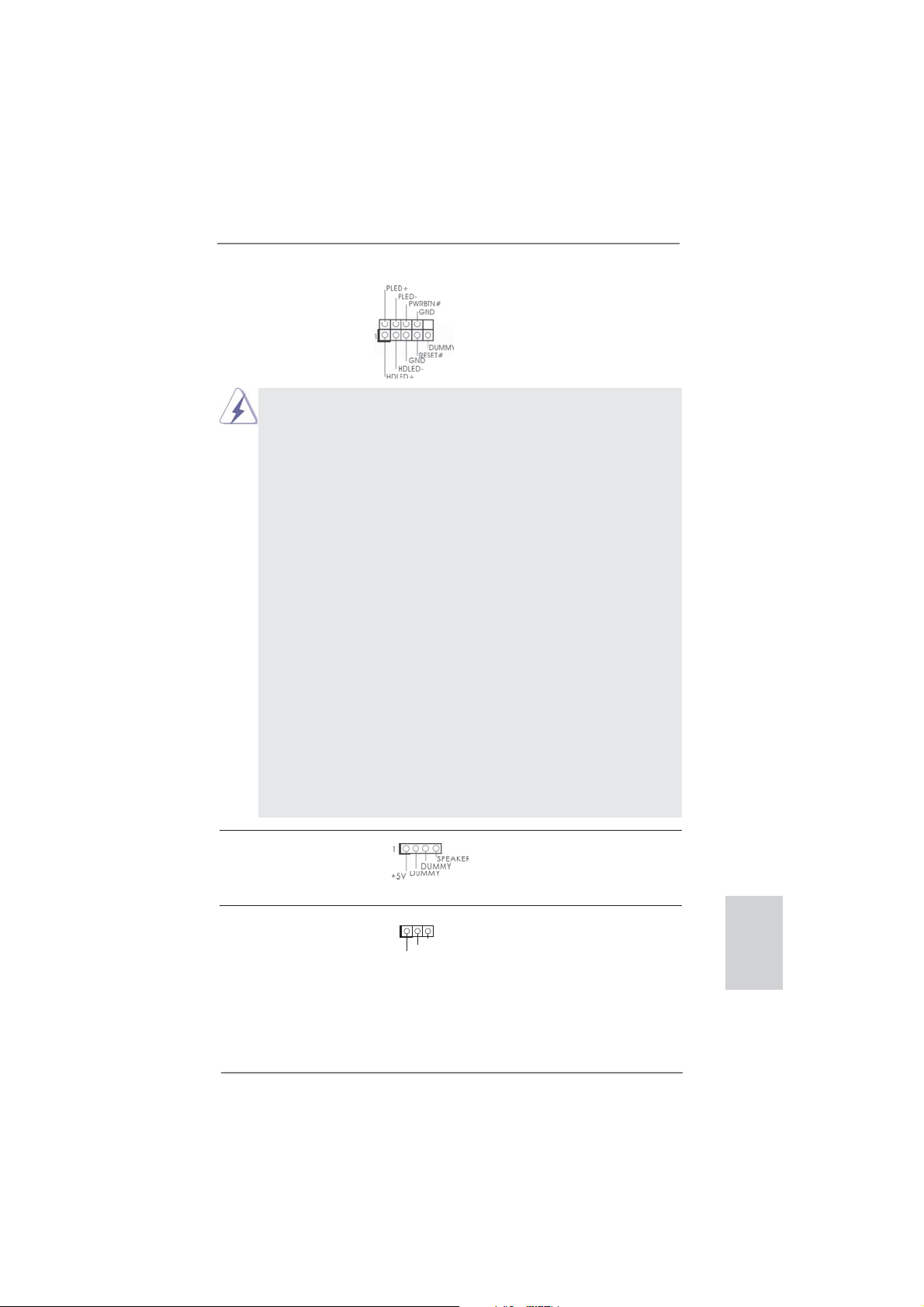
System Panel Header This header accommodates
(9-pin PANEL1)
(see p.2 No. 17)
several system front panel
functions.
Connect the power switch, reset switch and system status indicator
on the chassis to this header according to the pin assignments below.
Note the positive and negative pins before connecting the cables.
PWRBTN (Power Switch):
Connect to the power switch on the chassis front panel. You may confi gure the way to turn off your system using the power switch.
RESET (Reset Switch):
Connect to the reset switch on the chassis front panel. Press the reset
switch to restart the computer if the computer freezes and fails to perform a normal restart.
PLED (System Power LED):
Connect to the power status indicator on the chassis front panel. The
LED is on when the system is operating. The LED keeps blinking
when the sys-tem is in S1 sleep state. The LED is off when the system
is in S3/S4 sleep state or powered off (S5).
HDLED (Hard Drive Activity LED):
Connect to the hard drive activity LED on the chassis front panel. The
LED is on when the hard drive is reading or writing data.
The front panel design may differ by chassis. A front panel module
mainly consists of power switch, reset switch, power LED, hard drive
activity LED, speaker and etc. When connecting your chassis front
panel module to this header, make sure the wire assignments and the
pin assign-ments are matched correctly.
Chassis Speaker Header Please connect the chassis
(4-pin SPEAKER 1)
(see p.2 No. 21)
Power LED Header Please connect the chassis
(3-pin PLED1)
(see p.2 No. 16)
speaker to this header.
power LED to this header to
indicate system power status.
1
PLED+
PLED+
PLED-
The LED is on when the system
is operating. The LED keeps
blinking in S1 state. The LED is
off in S3/S4 state or S5 state
(power off).
ASRock FM2A85X Extreme6 Motherboard
English
27
Page 28
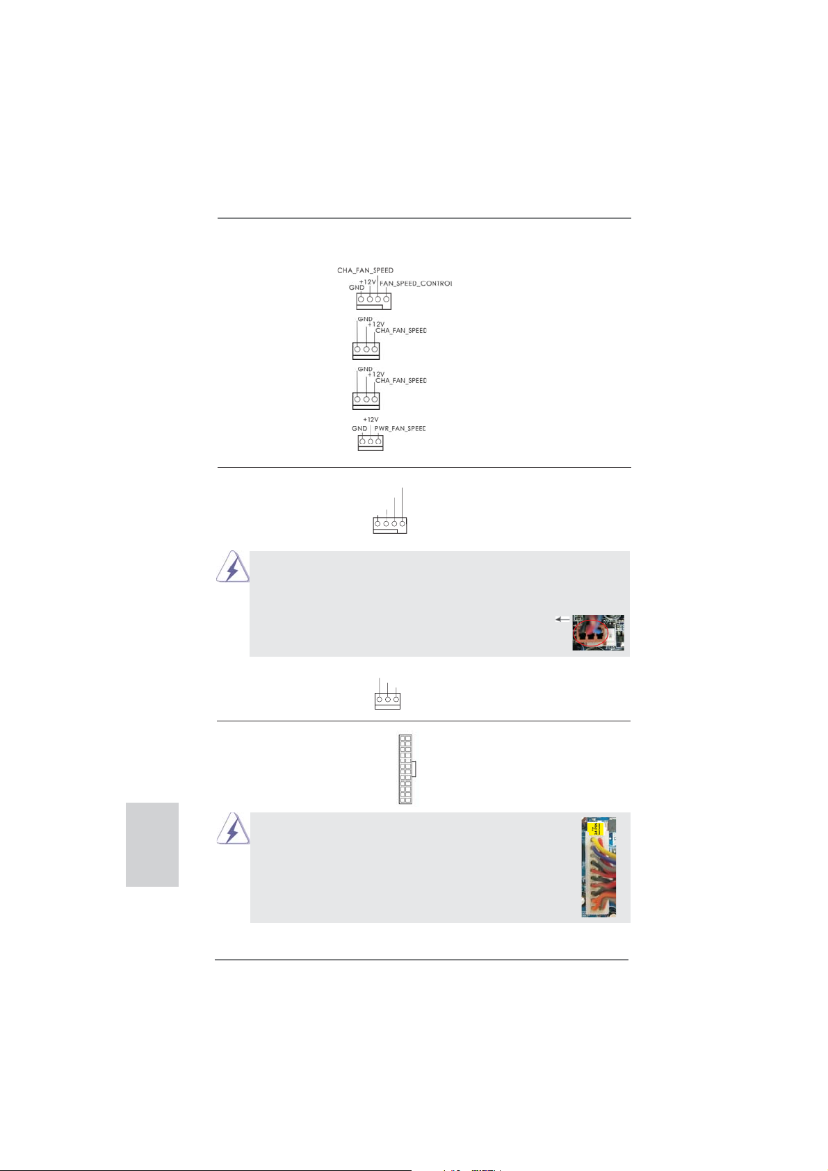
Chassis and Power Fan Connectors Please connect the fan cables
(4-pin CHA_FAN1)
(see p.2 No. 22)
to the fan connectors and
match the black wire to the
ground pin. CHA_FAN1/2/3 fan
(3-pin CHA_FAN2)
(see p.2 No. 41)
(3-pin CHA_FAN3)
(see p.2 No. 43)
(3-pin PWR_FAN1)
(see p.2 No. 4)
speed can be controlled through
UEFI or AXTU.
English
CPU Fan Connectors Please connect the CPU fan
(4-pin CPU_FAN1)
(see p.2 No. 5)
cable to the connector and
match the black wire to the
ground pin.
FAN_SPEED_CONTROL
CPU_FAN_SPEED
+12V
GND
1 2 3 4
Though this motherboard provides 4-Pin CPU fan (Quiet Fan) support, the 3-Pin
CPU fan still can work successfully even without the fan speed control function.
If you plan to connect the 3-Pin CPU fan to the CPU fan connector on this
motherboard, please connect it to Pin 1-3.
Pin 1-3 Connected
3-Pin Fan Installation
(3-pin CPU_FAN2)
(see p.2 No. 6)
ATX Power Connector Please connect an ATX power
(24-pin ATXPWR1)
(see p.2 No. 9)
Though this motherboard provides 24-pin ATX power connector,
it can still work if you adopt a traditional 20-pin ATX power supply.
GND
+12V
12
CPU_FAN_SPEED
24
supply to this connector.
1
13
12
To use the 20-pin ATX power supply, please plug your power
supply along with Pin 1 and Pin 13.
24
28
20-Pin ATX Power Supply Installation
ASRock FM2A85X Extreme6 Motherboard
1
13
Page 29
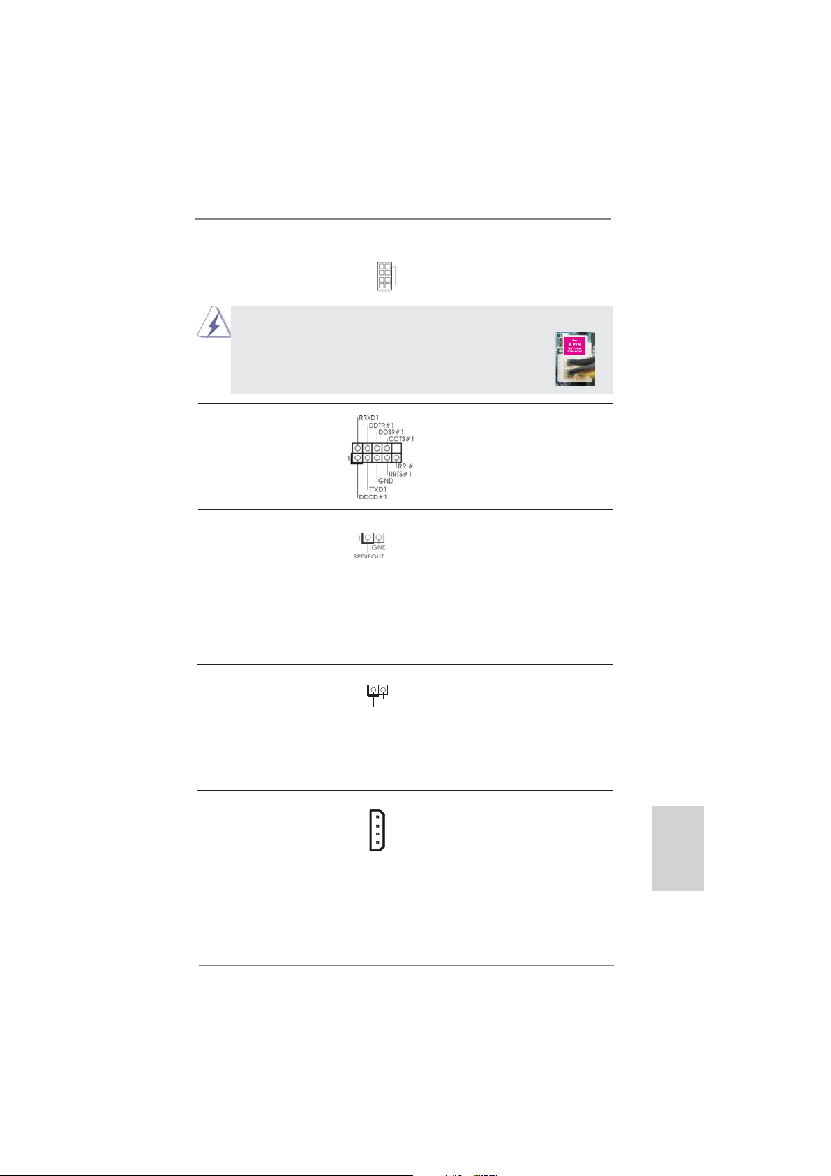
ATX 12V Power Connector Please connect an ATX 12V
(8-pin ATX12V1)
(see p.2 No. 1)
power supply to this connector.
4 8
1 5
Though this motherboard provides 8-pin ATX 12V power connector, it can still work
if you adopt a traditional 4-pin ATX 12V power supply. To use the
4-pin ATX power supply, please plug your power supply along with
Pin 1 and Pin 5.
4-Pin ATX 12V Power Supply Installation
4 8
1 5
Serial port Header This COM1 header supports a
(9-pin COM1)
(see p.2 No. 31)
serial port module.
HDMI_SPDIF Header HDMI_SPDIF header, providing
(2-pin HDMI_SPDIF1)
see p.2 No. 32)
(
SPDIF audio output to HDMI
VGA card, allows the system to
connect HDMI Digital TV/
projector/LCD devices. Please
connect the HDMI_SPDIF
connector of HDMI VGA card to
this header.
Chassis Intrusion Header This motherboard supports
(2-pin CI1)
CASE OPEN detection feature
(see p.2, No. 30)
that detects if the chassis cover
1
Signal
GND
has been removed. This feature
requires a chassis with chassis
intrusion detection design.
XFire Power Connector It is not necessary to use this
(4-pin CROSS_FIRE_PWR1)
(see p.2 No. 42)
with a hard disk power
connecor when two graphics
cards are plugged to this
connector, but please connect it
CROSS_FIRE_PWR1
motherboard.
29
ASRock FM2A85X Extreme6 Motherboard
English
Page 30
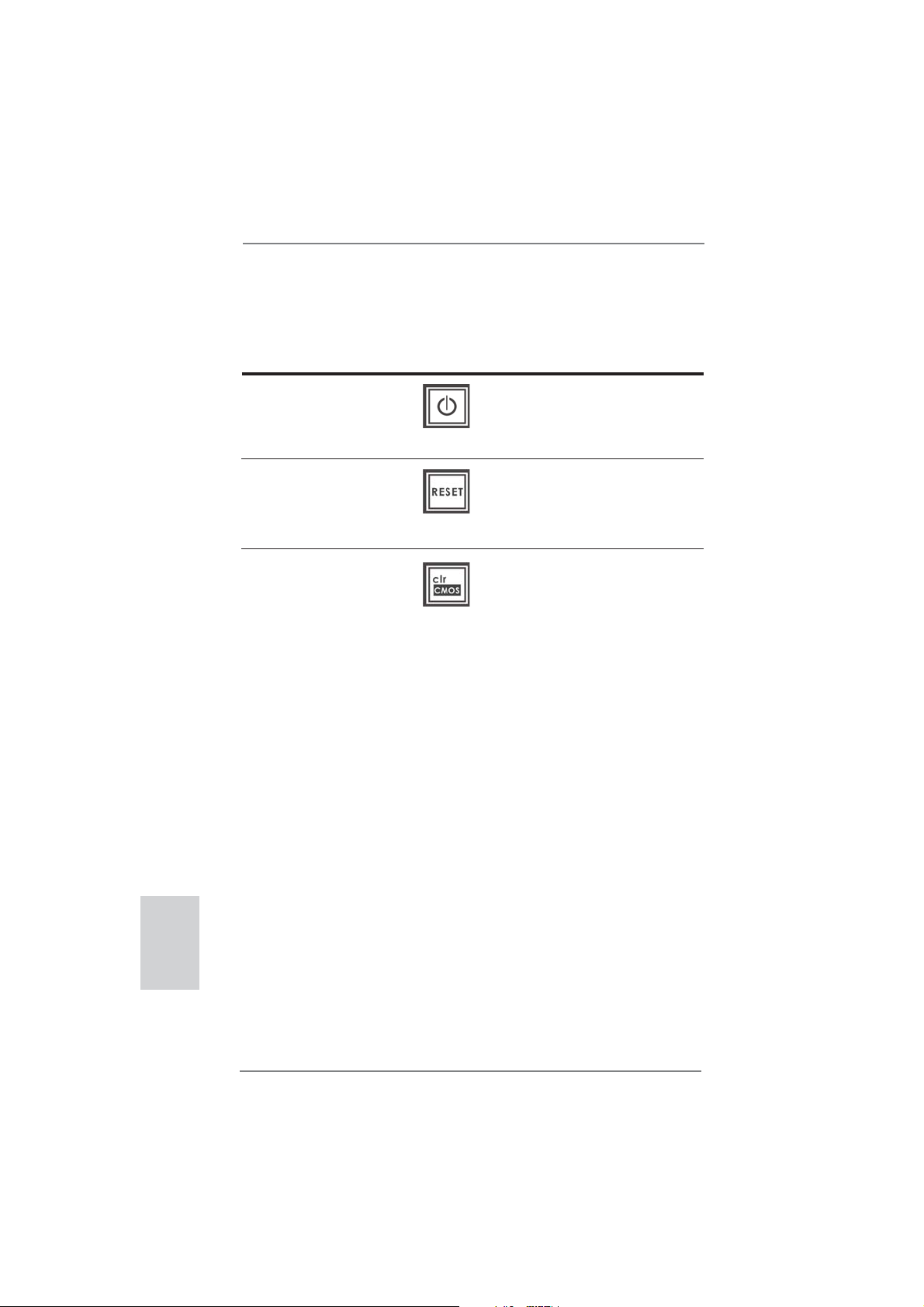
2.8 Smart Switches
This motherboard has three smart switches: power switch, reset switch and clear
CMOS switch, allowing users to quickly turn on/off or reset the system or clear the
CMOS values.
Power Switch Power Switch is a smart switch,
(PWRBTN)
(see p.2 No. 18)
Reset Switch Reset Switch is a smart switch,
(RSTBTN)
(see p.2 No. 20)
Clear CMOS Switch Clear CMOS Switch is a smart
(CLRCBTN)
(see p.3 No. 14)
allowing users to quickly turn
on/off the system.
allowing users to quickly reset
the system.
switch, allowing users to quickly
clear the CMOS values
English
30
ASRock FM2A85X Extreme6 Motherboard
Page 31

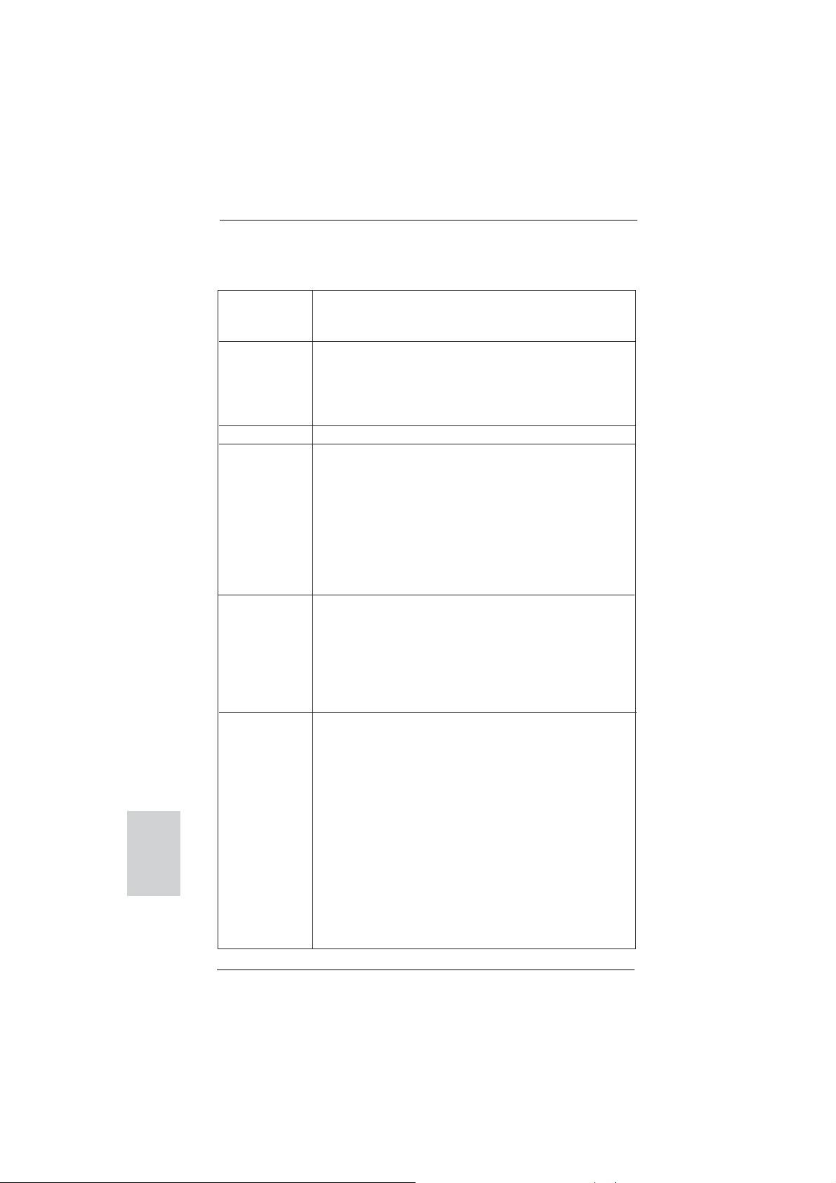
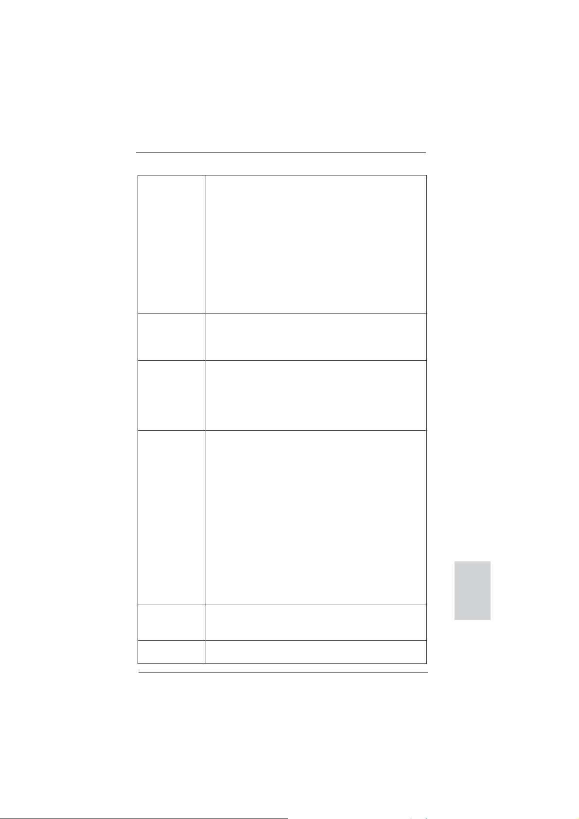
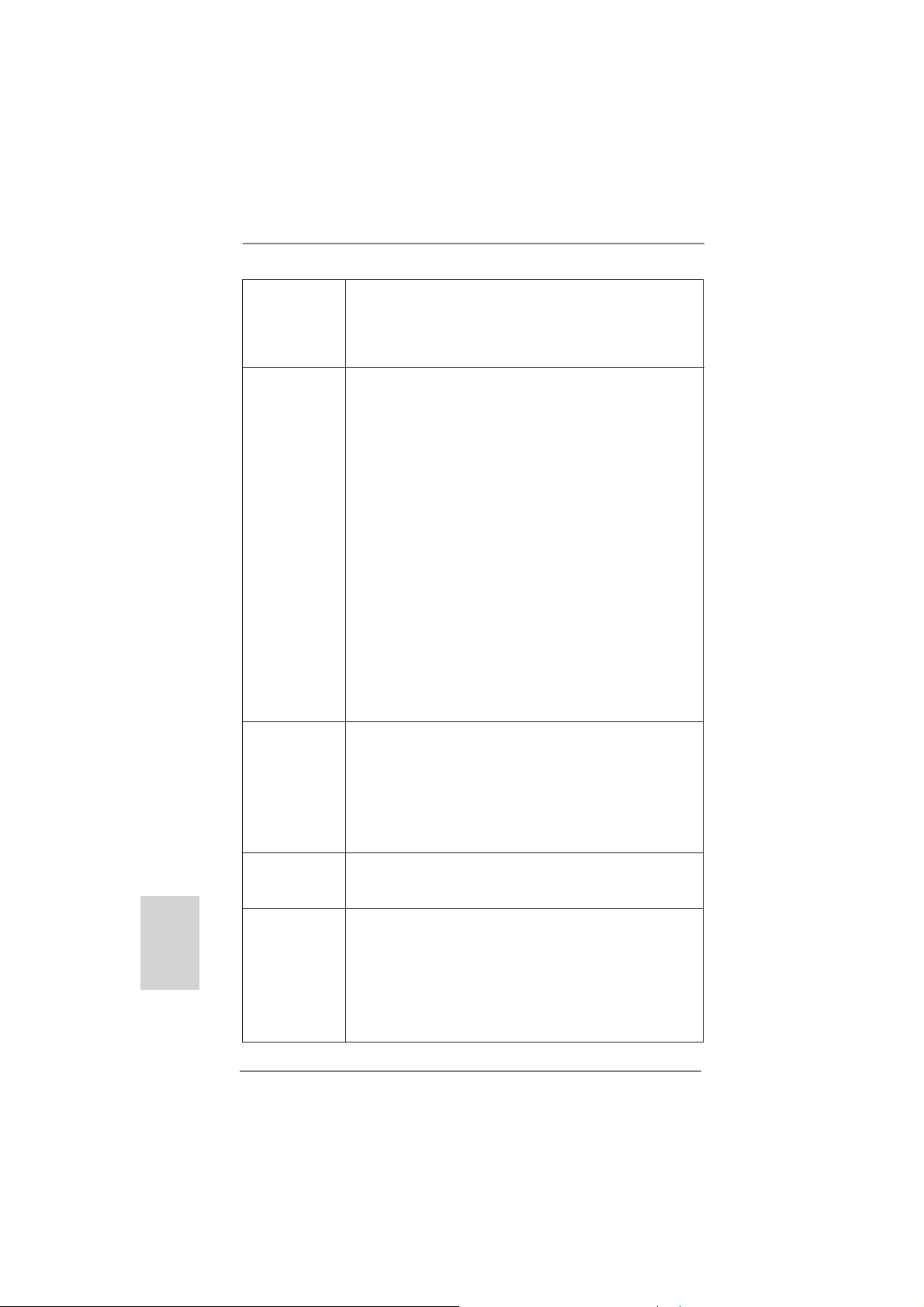
2.9 Dr. Debug
Dr. Debug is used to provide code information, which makes troubleshooting even
easier. Please see the diagrams below for reading the Dr. Debug codes.
Status Code Description
00 Please check if CPU is installed correctly and then clear CMOS.
0d Problem related to memory, VGA card and other devices.
Please clear CMOS, re-install memory and VGA card, and remove other
USB, PCI devices.
01 - 54 Problem related to memory. Please re-install CPU and memory then clear
(except 0d), CMOS.
5A- 60 If the problem still exists, please install only one memory module or try using
other memory modules.
55 Memory could not be detected. Please re-install memory and CPU.
If the problem still exists, please install only one memory module or try using
other memory modules.
61 - 91 Chipset initialization error. Please press reset or clear CMOS.
92 - 99 Problem related to PCI-E devices. Please re-install PCI-E devices or try
installing them in other slots.
If the problem still exists, please remove all PCI-E devices or try using
another VGA card.
A0 - A7 Problem related to IDE or SATA devices. Please re-install IDE and SATA
devices.
If the problem still exists, please clear CMOS and try removing all SATA
devices.
b0 Problem related to memory. Please re-install CPU and memory.
If the problem still exists, please install only one memory module or try using
other memory modules.
* For X79 models, please try installing memory to DDR3_A1, B1, C1 and D1
slots.
b4 Problem related to USB devices. Please try removing all USB devices.
b7 Problem related to memory. Please re-install CPU and memory then clear
CMOS.
If the problem still exists, please install only one memory module or try using
other memory modules.
d6 VGA could not be recognized. Please clear CMOS and try re-installing the
VGA card.
If the problem still exists, please try installing the VGA card in other slots or
using other VGA cards.
d7 Keyboard and mouse could not be recognized. Please try re-installing
keyboard and mouse.
d8 Invalid Password.
FF Please check if CPU is installed correctly and then clear CMOS.
English
ASRock FM2A85X Extreme6 Motherboard
31
Page 32

2.10 Driver Installation Guide
To install the drivers to your system, please insert the support CD to your optical
drive fi rst. Then, the drivers compatible to your system can be auto-detected and
listed on the support CD driver page. Please follow the order from up to bottom side
to install those required drivers. Therefore, the drivers you install can work properly.
2.11 Installing Windows® 8 / 8 64-bit / 7 / 7 64-bit / VistaTM /
Vista
If you want to install Windows® 8 / 8 64-bit / 7 / 7 64-bit / VistaTM / VistaTM 64-bit
on your SATA3 HDDs with RAID functions, please refer to the document at the
following path in the Support CD for detailed procedures:
..\ RAID Installation Guide
TM
64-bit With RAID Functions
2.12 Installing Windows® 8 / 8 64-bit / 7 / 7 64-bit / VistaTM /
VistaTM 64-bit Without RAID Functions
If you want to install Windows® 8 / 8 64-bit / 7 / 7 64-bit / VistaTM / VistaTM 64-bit on
your SATA3 HDDs without RAID functions, please follow below steps.
Using SATA3 HDDs without NCQ and Hot Plug functions (IDE mode)
English
STEP 1: Set up UEFI.
A. Enter UEFI SETUP UTILITY Advanced screen Storage
Confi guration.
B. Set the “SATA Mode” option to [IDE].
STEP 2: Install Windows
your system.
Using SATA3 HDDs with NCQ and Hot Plug functions (AHCI mode)
STEP 1: Set up UEFI.
A. Enter UEFI SETUP UTILITY Advanced screen Storage
Confi guration.
B. Set the “SATA Mode” option to [AHCI].
STEP 2: Install Windows
your system.
®
8 / 8 64-bit / 7 / 7 64-bit / VistaTM / VistaTM 64-bit OS on
®
8 / 8 64-bit / 7 / 7 64-bit / VistaTM / VistaTM 64-bit OS on
32
ASRock FM2A85X Extreme6 Motherboard
Page 33

3. BIOS Information
The Flash Memory on the motherboard stores BIOS Setup Utility. When you start up
the computer, please press <F2> or <Del> during the Power-On-Self-Test (POST)
to enter BIOS Setup utility; otherwise, POST continues with its test routines. If you
wish to enter BIOS Setup after POST, please restart the system by pressing <Ctl>
+ <Alt> + <Delete>, or pressing the reset button on the system chassis. The BIOS
Setup program is designed to be user-friendly. It is a menu-driven program, which
allows you to scroll through its various sub-menus and to select among the predetermined choices. For the detailed information about BIOS Setup, please refer to the
User Manual (PDF fi le) contained in the Support CD.
4. Software Support CD information
®
This motherboard supports various Microsoft
8 64-bit / 7 / 7 64-bit / VistaTM / Vista
motherboard contains necessary drivers and useful utilities that will enhance motherboard features. To begin using the Support CD, insert the CD into your CD-ROM
drive. It will display the Main Menu automatically if “AUTORUN” is enabled in your
computer. If the Main Menu does not appear automatically, locate and double-click
on the fi le “ASSETUP.EXE” from the BIN folder in the Support CD to display the
menus.
TM
Windows® operating systems: 8 /
64-bit. The Support CD that came with the
ASRock FM2A85X Extreme6 Motherboard
English
33
Page 34

1. Einführung
Wir danken Ihnen für den Kauf des ASRock FM2A85X Extreme6 Motherboard, ein
zuverlässiges Produkt, welches unter den ständigen, strengen Qualitätskontrollen
von ASRock gefertigt wurde. Es bietet Ihnen exzellente Leistung und robustes Design, gemäß der Verpfl ichtung von ASRock zu Qualität und Halbarkeit. Diese Sch-
nellinstallationsanleitung führt in das Motherboard und die schrittweise Installation
ein. Details über das Motherboard fi nden Sie in der Bedienungsanleitung auf der
Support-CD.
Da sich Motherboard-Spezifi kationen und BIOS-Software verändern
können, kann der Inhalt dieses Handbuches ebenfalls jederzeit geändert
werden. Für den Fall, dass sich Änderungen an diesem Handbuch
ergeben, wird eine neue Version auf der ASRock-Website, ohne weitere
Ankündigung, verfügbar sein. Die neuesten Grafi kkarten und unterstützten
CPUs sind auch auf der ASRock-Website aufgelistet.
ASRock-Website: http://www.asrock.com
Wenn Sie technische Unterstützung zu Ihrem Motherboard oder spezifi sche
Informationen zu Ihrem Modell benötigen, besuchen Sie bitte unsere
Webseite:
www.asrock.com/support/index.asp
1.1 Kartoninhalt
ASRock FM2A85X Extreme6 Motherboard (ATX-Formfaktor)
ASRock FM2A85X Extreme6 Schnellinstallationsanleitung
ASRock FM2A85X Extreme6 Support-CD
Vier Serial ATA (SATA) -Datenkabel (optional)
Ein I/O Shield
Deutsch
34
ASRock erinnert...
Zur besseren Leistung unter Windows® 8 / 8 64 Bit / 7 / 7 64 Bit / Vista
VistaTM 64 Bit empfehlen wir, die Speicherkonfi guration im BIOS auf den
AHCI-Modus einzustellen. Hinweise zu den BIOS-Einstellungen fi nden
Sie in der Bedienungsanleitung auf der mitgelieferten CD.
TM
ASRock FM2A85X Extreme6 Motherboard
/
Page 35

1.2 Spezifi kationen
Plattform - ATX-Formfaktor
- Hochwertiges Gold-Kondensatordesign (100 % hochwertige
japanische Fertigung leitfähiger Polymerkondensatoren)
CPU - Unterstützt Sockel-FM2-100-W-Prozessoren
- Digi Power-Design
- 8 + 2-Stromphasendesign
- Unterstützt Cool ‘n’ Quiet
- UMI-Link-GEN2
Chipsatz - AMD A85X (Hudson-D4)
Speicher - Unterstützung von Dual-Kanal-Speichertechnologie
- 4 x Steckplätze für DDR3
- Unterstützt DDR3 2600+(OC)/2400(OC)/2133(OC)/1866/
1600/1333/1066/800 non-ECC, ungepufferter Speicher
- Max. Kapazität des Systemspeichers: 64GB
- Unterstützt Intel
®
- Unterstützt AMD Memory Profi le (AMP)
Erweiterungs- - 3 x PCI Express 2.0 x16-St
steckplätze bei x16 (PCIE2) / x8 (PCIE4) oder dual im x8 (PCIE2) /
x8 (PCIE4)-Modus; PCIE5: x4-Modus)
- 2 x PCI Express 2.0 x1-Steckplätze
- 2 x PCI -Steckplätze
- Unterstützt AMD Quad CrossFireX
CrossFireXTM und duale Grafi kkarten
Onboard-VGA - AMD Radeon HD 7000-Grafi k
- DirectX 11, Pixel Shader 5.0
- Maximal gemeinsam genutzter Speicher 2GB
- Vier VGA-Ausgangsoptionen: D-Sub, DVI-D, HDMI sowie
DisplayPort
- Unterstützt HDMI 1.4a mit einer maximalen Aufl ösung von
1920 x 1200 bei 60 Hz
- Unterstützt Dual-link DVI mit einer maximalen Aufl ösung von
2560 x 1600 bei 75 Hz
- Unterstützt D-Sub mit einer maximalen Aufl ösung von
1920 x 1600 bei 60 Hz
- Unterstützt DisplayPort 1.2 mit einer maximalen Aufl ösung
von 4096 x 2160 bei 30 Hz
- Unterstützt DP++
- Unterstützt Multi-Streaming
- Unterstützt Auto Lip Sync, Deep Color (12bpc), xvYCC
TM
-Technologie von AMD
Extreme Memory Profi le (XMP)1.3/1.2
eckplätze (PCIE2/PCIE4: Einzeln
TM
, 3-Way CrossFireXTM,
Deutsch
ASRock FM2A85X Extreme6 Motherboard
35
Page 36

Deutsch
36
und HBR (High Bit Rate-Audio) mit HDMI (kompatibler
HDMI-Bildschirm erforderlich)
- Unterstützt stereoskopisches 3D per Blu-ray mit HDMI 1.4a
- Unterstützt AMD Steady VideoTM 2.0: Neuartige Funktion der
Videonachbearbeitung für automatische Reduzierung von
Bildschwankungen bei Heim-/Online-Videos
- Unterstützt HDCP-Funktion mit DVI- , HDMI- und Display
Port-Ports
- Unterstutzt 1080p Blu-ray (BD) / HD-DVD-Wiedergabe mit
DVI- , HDMI- und Display Port-Ports
Audio - 7.1
CH HD Audio mit dem Inhalt Schutz
(Realtek ALC898 Audio Codec)
- Premium Blu-ray-Audio-Unterstützung
- Unterstützt THX TruStudio
TM
LAN - PCIE x1 Gigabit LAN 10/100/1000 Mb/s
- Realtek RTL8111E
- Unterstützt Wake-On-LAN
- Unterstützt LAN-Kabelerkennung
- Unterstützt energieeffi zientes Ethernet 802.3az
- Unterstützt PXE
E/A-Anschlüsse I/O Panel
an der - 1 x PS/2-Maus/Tastaturanschluss
Rückseite - 1 x D-Sub port
- 1 x DVI-D port
- 1 x HDMI port
- 1 x DisplayPort
- 1 x optischer SPDIF-Ausgang
- 2 x Standard-USB 2.0-Anschlüsse
- 1 x eSATA3-Anschluss
- 4 x Standard-USB 3.0-Anschlüsse
- 1 x RJ-45 LAN Port mit LED (ACT/LINK LED und SPEED
LED)
- 1 x CMOS löschen-Schalter
- HD Audiobuchse: Lautsprecher hinten / Mitte/Bass /
Audioeingang / Lautsprecher vorne / Mikrofon
SATA3 - 7 x SATA 3-Anschluss mit 6,0 Gb/s, unterstützt RAID (RAID 0, RAID 1, RAID 5 und RAID 10), NCQ-, AHCI- und
„Hot Plugging“-Funktionen
USB3.0 - 2 x USB 3.0-Ports an der Rückseite durch AMD A85X
(Hudson-D4), unterstützt USB 1.1/2.0/3.0 mit bis zu 5 Gb/s
- 2 x USB 3.0-Ports an der Rückseite durch ASMedia
ASM1042, unterstützt USB 1.1/2.0/3.0 mit bis zu 5 Gb/s
ASRock FM2A85X Extreme6 Motherboard
Page 37

- 1 x USB 3.0-Header (unterstützt zwei USB 3.0-Ports) an der
Vorderseite durch AMD A85X (Hudson-D4), unterstützt
USB 1.1/2.0/3.0 mit bis zu 5 Gb/s
Anschlüsse - 7 x SATA3 6,0 GB/s-Anschlüsse
- 1 x Infrarot-Modul-Header
- 1 x
- 1 x COM-Anschluss-Header
- 1 x HDMI_SPDIF-Anschluss
- 1 x Betriebs-LED-Header
- 1 x Verteiler für Gehäuseeindringversuche
- 2 x CPUlüfter-Anschluss (1 x 4-pin, 1 x 3-pin)
- 3 x Gehäuselüfter-Anschluss (1 x 4-pin, 2 x 3-pin)
- 1 x Stromlüfter-Anschluss (3-pin)
- 24-pin ATX-Netz-Header
- 8-pin anschluss für 12V-ATX-Netzteil
- XFire-Netz-Header
- Anschluss für Audio auf der Gehäusevorderseite
- 3 x USB 2.0-Anschlüsse (Unterstützung 6 zusätzlicher
USB 2.0-Anschlüsse)
- 1 x USB 3.0-Anschlüsse (Unterstützung 2 zusätzlicher
USB 3.0-Anschlüsse)
- 1 x Dr. Debug (Debug-LED mit 7 Segmenten)
- 1 x Netzschalter mit LED
- 1 x Rücksetzschalter (Reset) mit LED
BIOS - 64Mb AMIs Legal BIOS UEFI mit GUI-Unterstützung
- Unterstützung für “Plug and Play”
- ACPI 1.1-Weckfunktionen
- JumperFree-Modus
- SMBIOS 2.3.1
- DRAM, APU PCIE VDDP, CPU und CPU NB/GFX
Stromspannung Multianpassung
Support-CD - Treiber, Dienstprogramme, Antivirussoftware
(Probeversion), CyberLink MediaEspresso 6.5-Testversion,
Google Chrome Browser und Toolbar
Hardware Monitor - CPU-Temperatursensor
- Motherboardtemperaturerkennung
- Drehzahlmessung für CPU/Gehäuse/Stromlüfter
- Geräuscharmer CPUlüfter
- Mehrstufi ge Geschwindigkeitsteuerung für CPU-/
Gehäuselüfter
Consumer Infrarot-Modul-Header
Deutsch
ASRock FM2A85X Extreme6 Motherboard
37
Page 38

- GEHÄUSE OFFEN-Erkennung
- Spannungsüberwachung: +12V, +5V, +3.3V, Vcore
®
Betriebssysteme - Unterstützt Microsoft
VistaTM / Vista
TM
64-Bit
Windows® 8 / 8 64-Bit / 7 / 7 64-Bit /
Zertifi zierungen - FCC, CE, WHQL
- Gemäß Ökodesign-Richtlinie (ErP/EuP) (Stromversorgung
gemäß Ökodesign-Richtlinie (ErP/EuP) erforderlich)
* Für die ausführliche Produktinformation, besuchen Sie bitte unsere Website:
http://www.asrock.com
Deutsch
38
ASRock FM2A85X Extreme6 Motherboard
Page 39

1.3 Einstellung der Jumper
Die Abbildung verdeutlicht, wie Jumper
gesetzt werden. Werden Pins durch
Jumperkappen verdeckt, ist der Jumper
“Gebrückt”. Werden keine Pins durch
Jumperkappen verdeckt, ist der Jumper
“Offen”. Die Abbildung zeigt einen 3-Pin
Jumper dessen Pin1 und Pin2 “Gebrückt” sind, bzw. es befi ndet sich eine
Jumper-Kappe auf diesen beiden Pins.
Jumper Einstellun Beschreibung
CMOS löschen
(CLRCMOS1, 3-Pin jumper)
(siehe S.2, No. 24)
Hinweis:
CLRCMOS1 ermöglicht Ihnen die Löschung der Daten im CMOS. Zum
Löschen und Zurücksetzen der Systemparameter auf die Standardeinrichtung
schalten Sie den Computer bitte aus und trennen das Netzkabel von der
Stromversorgung. Warten Sie 15 Sekunden, schließen Sie dann Pin2 und
Pin3 am CLRCMOS1 über einen Jumper fünf Sekunden lang kurz. Sie
sollten das CMOS allerdings nicht direkt nach der BIOS-Aktualisierung
löschen. Wenn Sie das CMOS nach Abschluss der BIOS-Aktualisierung
löschen müssen, fahren Sie zuerst das System hoch. Fahren Sie es dann
vor der CMOS-Löschung herunter. Bitte beachten Sie, dass Kennwort,
Datum, Uhrzeit, benutzerdefi niertes Profi l, 1394 GUID und MAC-Adresse
nur gelöscht werden, wenn die CMOS-Batterie entfernt wird.
DefaultEinstellung
CMOS
löschen
1. Der CMOS löschen-Schalter hat dieselbe Funktion wie der CMOS
löschen-Jumper.
2. Durch Löschen des CMOS kann erkannt werden, wenn das
Gehäuseoffen ist. Bitte stellen Sie zum Löschen der Aufzeichnung
des vorherigenGehäuseindringungsstatus die BIOS-Option “Status
leeren” ein.
ASRock FM2A85X Extreme6 Motherboard
Deutsch
39
Page 40

1.4 Anschlüsse
Anschlussleisten sind KEINE Jumper. Setzen Sie KEINE Jumperkappen
auf die Pins der Anschlussleisten. Wenn Sie die Jumperkappen auf die
Anschlüsse setzen, wird das Motherboard permanent beschädigt!
Anschluss Beschreibung
Seriell-ATA3-Anschlüsse Diese sieben Serial ATA3-
(SATA3_1_2: siehe S.2 - No. 12)
(SATA3_3_4: siehe S.2 - No. 13)
(SATA3_7_8: siehe S.2 - No. 14)
(SATA3_5: siehe S.2 - No. 15)
aktuelle SATA3- Schnittstelle
ermöglicht eine
Datenübertragungsrate bis
6,0 Gb/s.
Serial ATA- (SATA-) SJedes Ende des SATA
Datenkabel Datenkabels kann an die
(Option)
SATA3 Festplatte oder das
SATA3 Verbindungsstück auf
dieser Hauptplatine
angeschlossen werden.
(SATA3-)Verbínder
unterstützten SATA-Datenkabel
für interne
Massenspeichergeräte. Die
SATA3_8 SATA3_4 SATA3_2
SATA3_5
SATA3_7 SATA3_3 SATA3_1
Deutsch
40
USB 2.0-Header Zusätzlich zu den zwei
(9-pol. USB_0_1)
(siehe S.2 - No. 26)
üblichen USB 2.0-Ports an den
I/O-Anschlüssen befi nden sich
drei USB 2.0-
Anschlussleisten am
(9-pol. USB_2_3)
(siehe S.2 - No. 27)
Motherboard. Pro USB 2.0-
Anschlussleiste werden zwei
USB 2.0-Ports unterstützt.
(9-pol. USB_4_5)
(siehe S.2 - No. 28)
USB_PWR
1
USB_PWR
USB_PWR
1
USB_PWR
P-1
P+1
GND
DUMMY
GND
P+0
P-0
P-3
P+3
GND
DUMMY
GND
P+2
P-2
ASRock FM2A85X Extreme6 Motherboard
Page 41

USB 3.0-Header Neben vier Standard-USB
(19-pol. USB3_5_6)
(siehe S.2 - No. 10)
Header an diesem
Motherboard. Dieser USB 3.0 Header kann zwei USB 3.0 Ports unterstützen.
3.0-Ports am E/A-Panel
befi ndet sich ein USB 3.0-
Vbus
IntA_P5_SSRX-
IntA_P5_SSRX+
GND
IntA_P5_SSTX-
IntA_P5_SSTX+
GND
IntA_P5_D-
IntA_P5_D+
VbusVbus
IntA_P6_SSRX-
IntA_P6_SSRX+
GND
IntA_P6_SSTX-
IntA_P6_SSTX+
GND
IntA_P6_D-
IntA_P6_D+
DUMMY
Infrarot-Modul-Header Dieser Header unterstützt ein
(5-pin IR1)
optionales, drahtloses Sende-
(siehe S.2 - No. 23)
und Empfangs-Infrarotmodul.
IRTX
+5VSB
DUMMY
1
GND
IRRX
Consumer Infrared-Modul-Header Dieser Header kann zum
(4-pin CIR1)
(siehe S.2 - No. 29)
Anschluss für Audio auf Dieses Interface zu einem
der Gehäusevorderseite Audio-Panel auf der Vorder
(9-Pin HD_AUDIO1)
(siehe S.2 - No. 33)
Anschlussmöglichkeit und
Kontrolle über Audio-Geräte.
1. High Defi nition Audio unterstützt Jack Sensing (automatische Erkennung
falsch angeschlossener Geräte), wobei jedoch die Bildschirmverdrahtung
am Gehäuse HDA unterstützen muss, um richtig zu funktionieren.
Beachten Sie bei der Installation im System die Anweisungen in unserem
Handbuch und im Gehäusehandbuch.
2. Wenn Sie die AC’97-Audioleiste verwenden, installieren Sie diese wie
nachstehend beschrieben an der Front-Audioanschlussleiste:
A. Schließen Sie Mic_IN (MIC) an MIC2_L an.
B. Schließen Sie Audio_R (RIN) an OUT2_R und Audio_L (LIN) an OUT2_L an.
C. Schließen Sie Ground (GND) an Ground (GND) an.
Bei den Betriebssystemen Windows
64 Bit:
Wählen Sie im Realtek-Bedienfeld die „FrontMic“ (Vorderes Mikrofon)-
Registerkarte. Passen Sie die „Recording Volume“ (Aufnahmelautstärke)
an.
Anschließen Remote-
Empfänger.
GND
PRESENCE#
MIC_RET
OUT_RET
seite Ihres Gehäuses,
ermöglicht Ihnen eine bequeme
D. MIC_RET und OUT_RET sind nur für den HD-Audioanschluss gedacht. Diese
Anschlüsse müssen nicht an die AC’97-Audioleiste angeschlossen werden.
E. So aktivieren Sie das Mikrofon an der Vorderseite.
1
MIC2_R
MIC2_L
J_SENSE
OUT2_R
OUT2_L
®
8 / 8 64 Bit / 7 / 7 64 Bit / VistaTM / VistaTM
Deutsch
41
ASRock FM2A85X Extreme6 Motherboard
Page 42

System Panel-Header Dieser Header unterstützt
(9-pin PANEL1)
(siehe S.2 - No. 17)
Schließen Sie die Ein-/Austaste, die Reset-Taste und die
Systemstatusanzeige am Gehäuse an diesen Header an; befolgen Sie
dabei die nachstehenden Hinweise zur Pinbelegung. Beachten Sie die
positiven und negativen Pins, bevor Sie die Kabel anschließen.
PWRBTN (Ein-/Ausschalter):
RESET (Reset-Taste):
PLED (Systembetriebs-LED):
HDLED (Festplattenaktivitäts-LED):
mehrere Funktion der
Systemvorderseite.
Zum Anschließen des Ein-/Ausschalters an der Frontblende des Gehäu
ses. Sie können konfi gurieren, wie das System mit Hilfe des
Ein-/Ausschalters ausgeschaltet werden können soll.
Zum Anschließen der Reset-Taste an der Frontblende des Gehäuses.
Mit der Reset-Taste können Sie den Computer im Falle eines Absturzes
neu starten.
Zum Anschließen der Betriebsstatusanzeige an der Frontblende des
Gehäuses. Die LED leuchtet, wenn das System in Betrieb ist. Die LED
blinkt, wenn sich das System im Ruhezustand S1 befi ndet. Die LED
schaltet sich aus, wenn sich das System in den Modi S3/S4 befi ndet
oder ausgeschaltet ist (S5).
Zum Anschließen der Festplattenaktivitäts-LED an der Frontblende des
Gehäuses. Die LED leuchtet, wenn die Festplatte Daten liest oder
schreibt.
Deutsch
42
Das Design der Frontblende kann je nach Gehäuse variiere. Ein
Frontblendenmodul besteht hauptsächlich aus einer Ein-/Austaste, einer
Reset-Taste, einer Betriebs-LED, einer Festplattenaktivitäts-LED,
Lautsprechern, etc. Stellen Sie beim Anschließen des
Frontblendenmoduls Ihres Gehäuses an diesem Header sicher, dass die
Kabel- und Pinbelegung korrekt übereinstimmen.
ASRock FM2A85X Extreme6 Motherboard
Page 43

Gehäuselautsprecher-Header Schließen Sie den
(4-pin SPEAKER1)
(siehe S.2 - No. 21)
Gehäuselautsprecher an
diesen Header an.
Betriebs-LED-Header Bitte schließen Sie die
(3-pin PLED1)
(siehe S.2 - No. 16)
Betriebs-LED des Gehäuses
zur Anzeige des
1
PLED+
PLED+
PLED-
Systembetriebsstatus an
diesem Header an. Die LED
leuchtet, wenn das System in
Betrieb ist. Die LED blinkt im
S1-Zustand. Im S3-/S4- oder
S5-Zustand (ausgeschaltet)
leuchtet die LED nicht.
Gehäuse- und Stromlüfteranschlüsse Verbinden Sie die Lüfterkabel
(4-pin CHA_FAN1)
(siehe S.2, No. 22)
mit den Lüfteranschlüssen,
wobei der schwarze Draht an
den Schutzleiterstift
(3-pin CHA_FAN2)
(siehe S.2 - No. 41)
(3-pin CHA_FAN3)
(siehe S.2 - No. 43)
(3-pin PWR_FAN1)
(siehe S.2 - No. 4)
angeschlossenwird.
CPU-Lüfteranschluss Verbinden Sie das CPU -
(4-pin CPU_FAN1)
(siehe S.2 - No. 5)
Lüfterkabel mit diesem
Anschluss und passen Sie den
schwarzen Draht dem
Erdungsstift an.
FAN_SPEED_CONTROL
CPU_FAN_SPEED
+12V
GND
1 2 3 4
Obwohl dieses Motherboard einen vierpoligen CPU-Lüfteranschluss
(Quiet Fan) bietet, können auch CPU-Lüfter mit dreipoligem Anschluss
angeschlossen werden; auch ohne Geschwindigkeitsregulierung. Wenn
Sie einen dreipoligen CPU-Lüfter an den CPU-Lüferanschluss dieses
Motherboards anschließen möchten, verbinden Sie ihn bitte mit den
Pins 1 – 3.
Pins 1–3 anschließen
Lüfter mit dreipoligem Anschluss installieren
ASRock FM2A85X Extreme6 Motherboard
Deutsch
43
Page 44

(3-pin CPU_FAN2)
(siehe S.2 - No. 6)
GND
+12V
CPU_FAN_SPEED
ATX-Netz-Header Verbinden Sie die ATX-
(24-pin ATXPWR1)
(siehe S.2 - No. 9)
Obwohl dieses Motherboard einen 24-pol. ATX-
Stromversorgung mit diesem
Header.
12 124
13
12
24
Stromanschluss bietet, kann es auch mit einem
modifi zierten traditionellen 20-pol. ATX-Netzteil
verwendet werden. Um ein 20-pol. ATX-Netzteil zu
verwenden, stecken Sie den Stecker mit Pin 1 und
Pin 13 ein.
ATX 12V Anschluss Bitte schließen Sie an diesen
(8-pin ATX12V1)
(siehe S.2 - No. 1)
Anschluss die ATX 12V
Stromversorgung an.
Installation eines 20-pol. ATX-Netzteils
4 8
1 5
1
13
Obwohl diese Hauptplatine 8-Pin ATX 12V Stromanschluss zur
Verfügung stellt, kann sie noch arbeiten, wenn Sie einen
traditionellen 4-Pin ATX 12V Energieversorgung adoptieren. Um die
4-Pin ATX Energieversorgung zu verwenden, stecken Sie bitte Ihre
Energieversorgung zusammen mit dem Pin 1 und Pin 5 ein.
4 8
Deutsch
44
Installation der 4-Pin ATX 12V Energieversorgung
1 5
COM-Anschluss-Header Dieser COM-Anschluss-
(9-pin COM1)
(siehe S.2 - No. 31)
Header wird verwendet, um
ein COM-Anschlussmodul zu
unterstützen.
ASRock FM2A85X Extreme6 Motherboard
Page 45

HDMI_SPDIF-Anschluss Der HDMI_SPDIF-Anschluss
(2-pin HDMI_SPDIF1)
(siehe S.2 - No. 32)
stellt einen SPDIF-
Audioausgang für eine HDMI VGA-Karte zur Verfügung und
ermöglicht den Anschluss von
HDMI-Digitalgeräten wie
Fernsehgeräten, Projektoren,
LCD-Geräten an das System.
Bitte verbinden Sie den
HDMI_SPDIF-Anschluss der
HDMI-VGA-Karte mit diesem
Anschluss.
Verteiler für Gehäuseeindringversuche Dieses Motherboard unterstützt
(2-pin CI1)
die GEHÄUSE OFFEN-
(siehe S.2 - No. 30)
Erkennungsfunktion,die
feststellt, ob dieGehäuseab-
1
Signal
GND
deckung entferntwurde. Für
diese Funktion istein Ge häuse erforderlich, dasmit ei nem Design zur Erkennung
von Gehäuseeindringver suchenausgestattet ist.
XFire-Stromanschluss
(4-pin CROSS_FIRE_PWR1)
(siehe S.2 - No. 42)
Sie müssen diesen Anschluss
nicht zwingend verwenden.
Wenn allerdings zwei
CROSS_FIRE_PWR1
Grafi kkarten gleichzeitig am
Motherboard angeschlossen
sind, verbinden Sie diesen
Anschluss bitte mit einem
Festplatten-Stromversorgungsstecker.
ASRock FM2A85X Extreme6 Motherboard
Deutsch
45
Page 46

1.5 Schnellschalter
Dieses Motherboard besitzt drei Schnellschalter: Netzschalter, Rücksetzschalter
(Reset) und CMOS löschen-Schalter, mit denen Benutzer das System schnell ein-/
ausschalten oder zurücksetzen oder die CMOS-Werte löschen können.
Netzschalter Der Netzschalter ist ein
(PWRBTN)
(siehe S.2 - No. 18)
ein-/ausschalten können.
Rücksetzschalter (Reset) Der Rücksetzschalter (Reset)
(RSTBTN)
(siehe S.2 - No. 20)
zurücksetzen können.
CMOS löschen-Schalter Der CMOS löschen-Schalter ist
(CLRCBTN)
(siehe S.3 - No. 14)
schnell löschen können.
Schnellschalter, mit dem
Benutzer das System schnell
ist ein Schnellschalter, mit dem
Benutzer das System schnell
ein Schnellschalter, mit dem
Benutzer die CMOS-Werte
Deutsch
46
ASRock FM2A85X Extreme6 Motherboard
Page 47

2. BIOS-Information
Das Flash Memory dieses Motherboards speichert das Setup-Utility. Drücken Sie
<F2> oder <Del> während des POST (Power-On-Self-Test) um ins Setup zu gelangen, ansonsten werden die Testroutinen weiter abgearbeitet. Wenn Sie ins Setup
gelangen wollen, nachdem der POST durchgeführt wurde, müssen Sie das System
über die Tastenkombination <Ctrl> + <Alt> + <Delete> oder den Reset-Knopf auf
der Gehäusevorderseite, neu starten. Natürlich können Sie einen Neustart auch
durchführen, indem Sie das System kurz ab- und danach wieder anschalten.
Das Setup-Programm ist für eine bequeme Bedienung entwickelt worden. Es ist ein
menügesteuertes Programm, in dem Sie durch unterschiedliche Untermenüs scrollen und die vorab festgelegten Optionen auswählen können. Für detaillierte Informationen zum BIOS-Setup, siehe bitte das Benutzerhandbuch (PDF Datei) auf der
Support CD.
3. Software Support CD information
Dieses Motherboard unterstützt eine Reiche von Microsoft® Windows® Betriebssystemen: 8 / 8 64-Bit / 7 / 7 64-Bit / Vista
beigefügte Support-CD enthält hilfreiche Software, Treiber und Hilfsprogramme, mit
denen Sie die Funktionen Ihres Motherboards verbessern können Legen Sie die
Support-CD zunächst in Ihr CD-ROM-Laufwerk ein. Der Willkommensbildschirm
mit den Installationsmenüs der CD wird automatisch aufgerufen, wenn Sie die
“Autorun”-Funktion Ihres Systems aktiviert haben.
Erscheint der Wilkommensbildschirm nicht, so “doppelklicken” Sie bitte auf das File
ASSETUP.EXE im BIN-Verzeichnis der Support-CD, um die Menüs aufzurufen.
Das Setup-Programm soll es Ihnen so leicht wie möglich machen. Es ist menügesteuert, d.h. Sie können in den verschiedenen Untermenüs Ihre Auswahl treffen und
die Programme werden dann automatisch installiert.
TM
/ VistaTM 64-Bit. Die Ihrem Motherboard
ASRock FM2A85X Extreme6 Motherboard
Deutsch
47
Page 48

1. Introduction
Merci pour votre achat d’une carte mère ASRock FM2A85X Extreme6, une carte
mère très fiable produite selon les critères de qualité rigoureux de ASRock. Elle
offre des performances excellentes et une conception robuste conformément à
l’engagement d’ASRock sur la qualité et la fi abilité au long terme.
Ce Guide d’installation rapide présente la carte mère et constitue un guide
d’installation pas à pas. Des informations plus détaillées concernant la carte
mère pourront être trouvées dans le manuel l’utilisateur qui se trouve sur le CD
d’assistance.
Les spécifi cations de la carte mère et le BIOS ayant pu être mis à
jour, le contenu de ce manuel est sujet à des changements sans
notifi cation. Au cas où n’importe qu’elle modifi cation intervenait sur ce
manuel, la version mise à jour serait disponible sur le site web
ASRock sans nouvel avis. Vous trouverez les listes de prise en
charge des cartes VGA et CPU également sur le site Web ASRock.
Site web ASRock, http://www.asrock.com
Si vous avez besoin de support technique en relation avec cette carte
mère, veuillez consulter notre site Web pour de plus amples
informations particulières au modèle que vous utilisez.
www.asrock.com/support/index.asp
1.1 Contenu du paquet
Carte mère ASRock FM2A85X Extreme6 (Facteur de forme ATX)
Guide d’installation rapide ASRock FM2A85X Extreme6
CD de soutien ASRock FM2A85X Extreme6
Quatre câbles de données de série ATA (SATA) (en option)
Un I/O Panel Shield
Français
48
ASRock vous rappelle...
Pour bénéfi cier des meilleures performances sous Windows® 8 / 8 64 bits
/ 7 / 7 64 bits / Vista
l'option BIOS dans Confi guration de stockage en mode AHCI. Pour plus
de détails sur l'installation BIOS, référez-vous au "Mode d'emploi" sur
votre CD de support.
TM
/ VistaTM 64 bits, il est recommandé de paramétrer
ASRock FM2A85X Extreme6 Motherboard
Page 49

1.2 Spécifi cations
Format - Facteur de forme ATX
- Design de condensateur Premium Gold (condensateurs
polymère conducteur de qualité supérieure 100% fabriqués
au Japon)
CPU - Support des unités centrales Socket FM2 100W
- Conception Digi Power
- Conception 8 + 2 Power Phase
- Supporte la technologie Cool ‘n’ Quiet
- UMI-Link GEN2
Chipsets - AMD A85X (Hudson-D4)
Mémoire - Compatible avec la Technologie de Mémoire à Canal
Double
- 4 x slots DIMM DDR3
- Supporter DDR3 2600+(OC)/2400(OC)/2133(OC)/1866/
1600/1333/1066/800 non-ECC, sans amortissement
mémoire
- Capacité maxi de mémoire système: 64GB
- Prend en charge le profi l de mémoire extrême Intel
1.3/1.2
- Prend en charge le profi l de mémoire AMD (AMP)
Slot d’extension - 3 x slots PCI Express 2.0 x16 (PCIE2/PCIE4: simple à x16
(PCIE2) / x8 (PCIE4) ou double en mode x8 (PCIE2) /x8
(PCIE4); PCIE5 à mode x4)
- 2 x slots PCI Express 2.0 x1
- 2 x slots PCI
- Support de AMD Quad CrossFireX
CrossFireXTM et Dual Graphics
VGA sur carte - Graphiques à l’AMD Radeon HD 7000
- DirectX 11, nuanceur de pixels 5.0
- mémoire partagée max 2GB
- Quatre options de sortie VGA: D-Sub, DVI-D, HDMI et
DisplayPort
- Prend en charge le HDMI 1.4a avec une résolution
maximale jusqu’à 1920x1200 @ 60Hz
- Prend en charge le Dual-link DVI avec une résolution
maximale jusqu’à 2560x1600 @ 75Hz
- Prend en charge le D-Sub avec une résolution maximale
jusqu’à 1920x1600 @ 60Hz
- Prend en charge le DisplayPort 1.2 avec une résolution
TM
d’AMD
®
(XMP)
TM
, 3-Way CrossFireXTM,
Français
ASRock FM2A85X Extreme6 Motherboard
49
Page 50

Français
maximale jusqu’à 4096x2160 @ 30Hz
- Supporte DP++
- Supporte Multi-Streaming
- Prend en charge Lip Sync, Deep Color (12bpc), xvYCC et
HBR (High Bit Rate Audio: Audio à haut débit binaire) avec
HDMI (Moniteur compatible HDMI requis)
- Prend en charge la 3D stéréoscopique Blu-ray avec
HDMI 1.4a
- Supporte AMD Steady Video
TM
2.0: Nouvelle fonctionnalité
de traitement post-vidéo pour réduction automatique des
tremblements dans les clips vidéo en ligne/maison
- Prise en charge de la fonction HDCP avec ports DVI, HDMI
et DisplayPort
- Supporter 1080p Blu-ray(BD)/ lecteur de HD-DVD avec
ports DVI, HDMI et DisplayPort
Audio - 7,1 CH HD Audio avec protection de contenu
(Realtek ALC898 Audio Codec)
- Prise en charge de l’audio Premium Blu-ray
- Prend en charge THX TruStudio
TM
LAN - PCIE x1 Gigabit LAN 10/100/1000 Mb/s
- Realtek RTL8111E
- Supporte du Wake-On-LAN
- Prise en charge de la détection de câble LAN
- Prend en charge la norme Energy Effi cient Ethernet
(Ethernet à effi cacité énergétique) 802.3az
- Supporte PXE
Panneau arrière I/O Panel
- 1 x port souris/clavier PS/2
- 1 x port D-Sub
- 1 x port DVI-D
- 1 x port HDMI
- 1 x DisplayPort
- 1 x Port de sortie optique SPDIF
- 2 x ports USB 2.0 par défaut
- 1 x Connecteur eSATA3
- 4 x ports USB 3.0 par défaut
- 1 x port LAN RJ-45 avec LED (ACT/LED CLIGNOTANTE et
LED VITESSE)
- 1 x interrupteur d’effacement du CMOS
- Prise HD Audio: Haut-parleur arrière / Central /Basses /
Entrée Ligne / Haut-parleur frontal / Microphone
50
ASRock FM2A85X Extreme6 Motherboard
Page 51

SATA 3 - 7 x connecteurs 6,0 Gb/s SATA3, prise en charge des
fonctions RAID (RAID 0, RAID 1, RAID 5 et RAID 10), NCQ,
AHCI et « Connexion à chaud »
USB 3.0 - 2 x ports USB3.0 à l’arrière par AMD A85X (Hudson-D4),
prennent en charge USB 1.1/2.0/3.0 jusqu’à 5 Gb/s
- 2 x ports USB3.0 à l’arrière par ASMedia ASM1042,
prennent en charge USB 1.1/2.0/3.0 jusqu’à 5 Gb/s
- 1 x barrette USB3.0 en façade (prend en charge 2 ports
USB 3.0) par AMD A85X (Hudson-D4), prend en charge
USB 1.1/2.0/3.0 jusqu’à 5 Gb/s
Connecteurs - 7 x connecteurs SATA3, prennent en charge un taux de
transfert de données pouvant aller jusqu’à 6.0Go/s
- 1 x En-tête du module infrarouge
- 1 x
- 1 x En-tête de port COM
- 1 x Connecteur HDMI_SPDIF
- 1 x LED di accensione
- 1 x Embase d’intrusion châssis
- 2 x Connecteur pour ventilateur de CPU (1 x br. 4, 1 x br. 3)
- 3 x Connecteur pour ventilateur de Châssis
(1 x br. 4, 2 x br. 3)
- 1 x Connecteur pour ventilateur de pouvoir (br. 3)
- br. 24 connecteur d’alimentation ATX
- br. 8 connecteur d’alimentation 12V ATX
- Connecteur d’alimentation XFire
- Connecteur audio panneau avant
- 3 x En-tête USB 2.0 (prendre en charge 6 ports USB 2.0
supplémentaires)
- 1 x En-tête USB 3.0 (prendre en charge 2 ports USB 3.0
supplémentaires)
- 1 x Dr. Debug (LED de débogage à 7 segments)
- 1 x interrupteur d’alimentation avec LED
- 1 x interrupteur de réinitialisation avec LED
BIOS - 64Mb AMI UEFI Legal BIOS avec support GUI
- Support du “Plug and Play”
- Compatible pour événements de réveil ACPI 1.1
- Gestion jumperless
- Support SMBIOS 2.3.1
- DRAM, APU PCIE VDDP, CPU et CPU NB/GFX Tension
Multi-ajustement
Barrette pour module à infrarouges grand public
Français
ASRock FM2A85X Extreme6 Motherboard
51
Page 52

CD d’assistance - Pilotes, utilitaires, logiciel anti-virus (Version d’essai),
CyberLink MediaEspresso 6.5 Trial, Google Chrome
Browser et Toolbar
Surveillance - Détection de la température de l’UC
système - Mesure de température de la carte mère
- Tachéomètre ventilateur CPU/Châssis/Ventilateur
- Ventilateur silencieux pour unité centrale
- Commande de ventilateur CPU/boîtier à plusieurs vitesses
- Détection d’OUVERTURE DE BOÎTIER
- Monitoring de la tension: +12V, +5V, +3.3V, Vcore
OS - Microsoft
®
Windows® 8 / 8 64-bit / 7 / 7 64-bit / Vista
TM
/
VistaTM 64-bit
Certifi cations - FCC, CE, WHQL
- Prêt pour ErP/EuP (alimentation Prêt pour ErP/EuP requise)
* Pour de plus amples informations sur les produits, s’il vous plaît visitez notre site web:
http://www.asrock.com
Français
52
ASRock FM2A85X Extreme6 Motherboard
Page 53
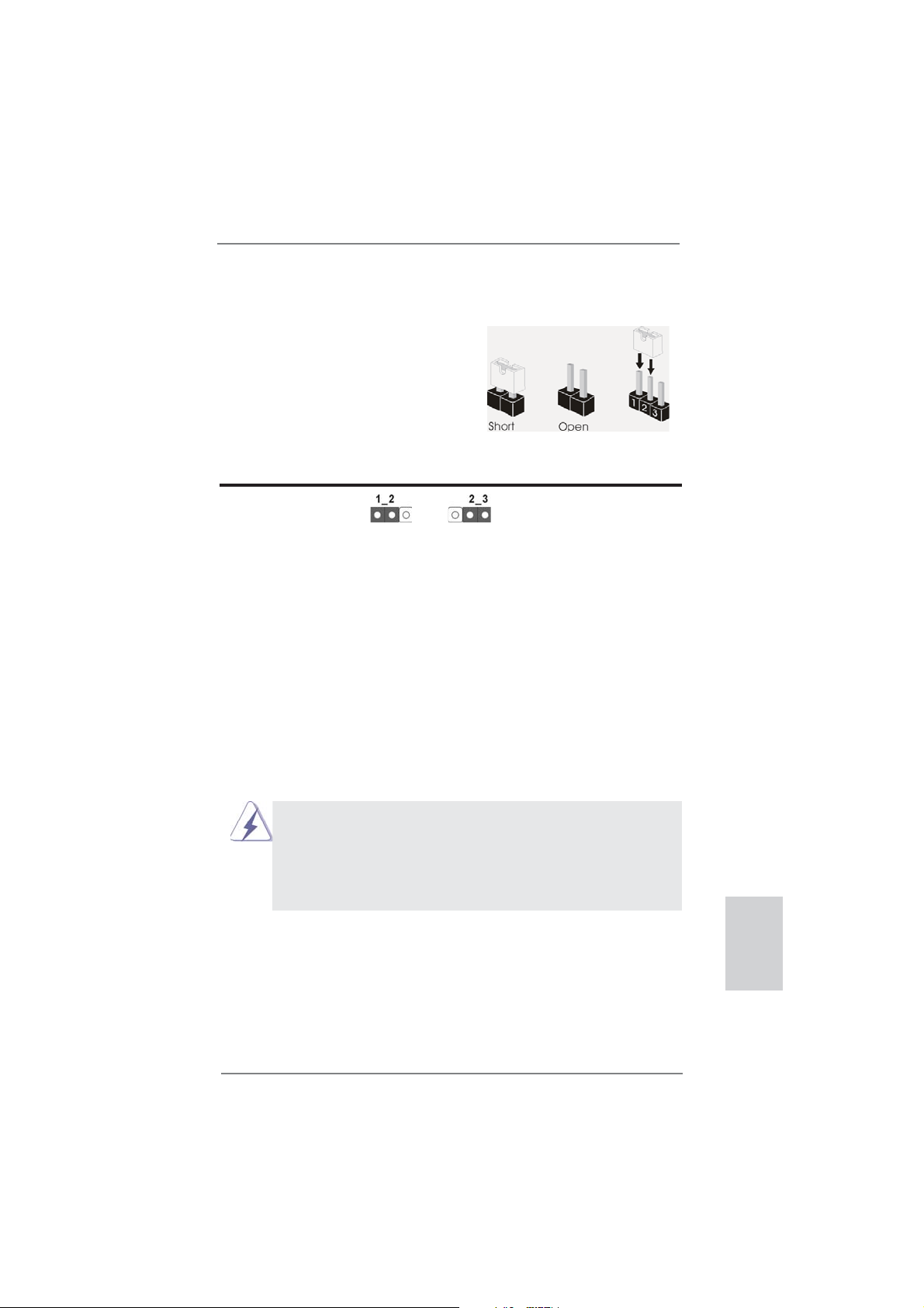
1.3 Réglage des cavaliers
L’illustration explique le réglage des cavaliers. Quand un capuchon est placé sur les
broches, le cavalier est « FERME ». Si aucun capuchon ne relie les broches,le cavalier est « OUVERT ». L’illustration montre un
cavalier à 3 broches dont les broches 1 et 2
sont « FERMEES » quand le capuchon est
placé sur ces 2 broches.
Le cavalier Description
Effacer la CMOS
(CLRCMOS1)
(voir p.2 fi g. 24)
Remarque :
Paramètres
par défaut
CLRCMOS1 vous permet d’effacer les données du CMOS. Pour effacer
et réinitialiser les paramètres du système à la confi guration originale,
veuillez éteindre l’ordinateur et débrancher le cordon d’alimentation de
la prise de courant. Après 15 secondes, utilisez un couvercle de jumper
pour court-circuiter les broches pin2 et pin3 de CLRCMOS1 pendant
secondes. Veuillez cependant ne pas effacer le CMOS immédiatement
a
près avoir mis à jour le BIOS. Si vous avez besoin d’effacer le CMOS
après avoir mis à jour le BIOS, vous devez allumer en premier le
système, puis l’éteindre avant de continuer avec l’opération d’effacement
du CMOS. Veuillez noter que le mot de passe, la date, l’heure, le profi l
par défaut de l’utilisateur, 1394 GUID et l’adresse MAC seront effacés
seulement si la batterie du CMOS est enlevée.
Effacer la
CMOS
5
1. Le commutateur Effacer CMOS présente la même fonction que le
cavalier Effacer CMOS.
2. Si vous effacez la CMOS, il se peut qu’une ouverture du boîtier
soitdétectée. Veuillez ajuster l’option du BIOS “Clear Status”
(Effacerl’état) pour effacer la mention d’état d’intrusion dans le
châssis.
ASRock FM2A85X Extreme6 Motherboard
Français
53
Page 54

1.4 En-têtes et Connecteurs sur Carte
Connecteurs Série ATA3 Ces sept connecteurs Série
(SATA3_1_2: voir p.2 No. 12)
(SATA3_3_4: voir p.2 No. 13)
(SATA3_7_8: voir p.2 No. 14)
(SATA3_5: voir p.2 No. 15)
actuelle permet des taux
transferts de données pouvant
aller jusqu’à 6,0 Gb/s.
Câble de données Toute cote du cable de data
Série ATA (SATA) SATA peut etre connecte au
(en option)
connecteur SATA3 sur la carte
mere.
Les en-têtes et connecteurs sur carte NE SONT PAS des cavaliers.
NE PAS placer les capuchons de cavalier sur ces en-têtes et connecteurs. Le fait de placer les capuchons de cavalier sur les entêtes et connecteurs causera à la carte mère des dommages irréversibles!
ATA3 (SATA3) prennent en
charge les câbles SATA pour
les périphériques de stockage
internes. L’interface SATA3
SATA3_8 SATA3_4 SATA3_2
SATA3_5
SATA3_7 SATA3_3 SATA3_1
disque dur SATA3 ou au
Français
54
En-tête USB 2.0 A côté des deux ports USB
(USB_0_1 br.9)
(voir p.2 No. 26)
2.0 par défaut sur le panneau
E/S, il y a trois embases USB
2.0 sur cette carte mère.
Chaque embase USB 2.0 peut
(USB_2_3 br.9)
(voir p.2 No. 27)
(USB_4_5 br.9)
(voir p.2 No. 28)
prendre en charge 2 ports USB
2.0.
USB_PWR
1
USB_PWR
USB_PWR
1
USB_PWR
P-1
P+1
GND
DUMMY
GND
P+0
P-0
P-3
P+3
GND
DUMMY
GND
P+2
P-2
ASRock FM2A85X Extreme6 Motherboard
Page 55

En-tête USB 3.0 En plus des quatre ports USB
(USB3_5_6 br. 19)
(voir p.2 No. 10)
sur la carte mère. Cette barrette
USB 3.0 peut prendre en
charge deux ports USB 3.0.
3.0 par défaut sur le panneau
E/S, il y a une barrette USB 3.0
Vbus
IntA_P5_SSRX-
IntA_P5_SSRX+
GND
IntA_P5_SSTX-
IntA_P5_SSTX+
GND
IntA_P5_D-
IntA_P5_D+
VbusVbus
IntA_P6_SSRX-
IntA_P6_SSRX+
GND
IntA_P6_SSTX-
IntA_P6_SSTX+
GND
IntA_P6_D-
IntA_P6_D+
DUMMY
En-tête du module infrarouge Cet en-tête supporte un module
(IR1 br.5)
infrarouge optionnel de
(voir p.2 No. 23)
transfert et de réception sans
fi l.
IRTX
+5VSB
DUMMY
1
GND
IRRX
Barrette pour module à infrarouges grand public Cette barrette peut être utilisée
(CIR1 br.4)
(voir p.2 No. 29)
Connecteur audio panneau C’est une interface pour
(HD_AUDIO1 br. 9)
(voir p.2 No. 33)
le contrôle commodes de
périphériques audio.
1. L’audio à haute défi nition (HDA) prend en charge la détection de fi che,
mais le fi l de panneau sur le châssis doit prendre en charge le HDA pour
fonctionner correctement. Veuillez suivre les instructions dans notre
manuel et le manuel de châssis afi n installer votre système.
2. Si vous utilisez le panneau audio AC’97, installez-le sur l’adaptateur audio
du panneau avant conformément à la procédure ci-dessous :
A. Connectez Mic_IN (MIC) à MIC2_L.
B. Connectez Audio_R (RIN) à OUT2_R et Audio_L (LIN) à OUT2_L.
C. Connectez Ground (GND) à Ground (GND).
D. MIC_RET et OUT_RET sont réservés au panneau audio HD. Vous
n’avez pas besoin de les connecter pour le panneau audio AC’97.
E. Pour activer le micro avant.
Pour les systèmes d’exploitation Windows
VistaTM 64 bits :
Allez sur l’onglet “FrontMic” (Micro avant) sur le Panneau de contrôle
Realtek. Ajustez “Recording Volume” (Volume d’enregistrement).
pour connecter des récepteur
GND
PRESENCE#
un câble avant audio en façade
MIC_RET
OUT_RET
qui permet le branchement et
1
MIC2_R
MIC2_L
J_SENSE
OUT2_R
OUT2_L
®
8 / 8 64 bits / 7 / 7 64 bits / VistaTM /
Français
ASRock FM2A85X Extreme6 Motherboard
55
Page 56

En-tête du panneau système Cet en-tête permet d’utiliser
(PANEL1 br.9)
(voir p.2 No. 17)
Connectez l’interrupteur d’alimentation, l’interrupteur de réinitialisation et
l’indicateur d’état du système du châssis sur cette barrette en respectant
l’affectation des broches décrite ci-dessous. Faites attention aux broches
positives et négatives avant de connecter les câbles.
PWRBTN (Interrupteur d’alimentation):
RESET (Interrupteur de réinitialisation):
PLED (DEL alimentation système):
HDLED (DEL activité du disque dur):
plusieurs fonctions du
panneau système frontal.
Connectez ici le connecteur d’alimentation sur le panneau avant du
châssis. Vous pouvez confi gurer la façon de mettre votre système hors
tension avec l’interrupteur d’alimentation.
Connectez ici le connecteur de réinitialisation sur le panneau avant du
châssis. Appuyez sur l’interrupteur de réinitialisation pour redémarrer
l’ordinateur s’il se bloque ou s’il n’arrive pas à redémarrer normalement.
Connectez ici l’indicateur d’état de l’alimentation sur le panneau avant
du châssis. Ce voyant DEL est allumé lorsque le système est en
marche. Le voyant DEL clignote lorsque le système est en mode veille
S1. Le voyant DEL est éteint lorsque le système est en mode veille S3/
S4 ou lorsqu’il est éteint (S5).
Connectez ici le voyant DEL d’activité du disque dur sur le panneau
avant du châssis. Ce voyant DEL est allumé lorsque le disque dur est en
train de lire ou d’écrire des données.
Français
56
Le design du panneau avant peut varier en fonction du châssis. Un
module de panneau avant consiste principalement en : interrupteur
d’alimentation, interrupteur de réinitialisation, voyant DEL d’alimentation,
voyant DEL d’activité du disque dur, haut-parleur, etc. Lorsque vous
connectez le panneau avant de votre châssis sur cette barrette, vérifi ez
bien à faire correspondre les fi ls et les broches.
ASRock FM2A85X Extreme6 Motherboard
Page 57

En-tête du haut-parleur Veuillez connecter le
de châssis haut-parleur de châssis sur
(SPEAKER1 br. 4)
(voir p.2 No. 21)
cet en-tête.
LED di accensione Collegare il LED di accensione
(3-pin PLED1)
(vedi p.2 Nr. 16)
chassi per indicare lo stato di
alimentazione del sistema. Il
1
PLED+
PLED+
PLED-
LED è acceso quando il sistema
è in funzione. Il LED continua a
lampeggiare in stato S1. Il LED
è spento in stato S3/S4 o S5
(spegnimento).
Connecteur pour châssis et ventilateur
(CHA_FAN1 br. 4)
(voir p.2 No. 22)
Branchez les câbles du
ventilateur aux connecteurs pour
ventilateur et faites correspondre
le fi l noir à la broche de terre.
(CHA_FAN2 br. 3)
(voir p.2 No. 41)
(CHA_FAN3 br. 3)
(voir p.2 No. 43)
(PWR_FAN1 br. 3)
(voir p.2 No. 4)
Connecteur du ventilateur Veuillez connecter le câble de
de l’UC ventilateur d’UC sur ce
(CPU_FAN1 br. 4)
(voir p.2 No. 5)
FAN_SPEED_CONTROL
CPU_FAN_SPEED
+12V
connecteur et brancher le fi l
noir sur la broche de terre.
GND
1 2 3 4
Bien que cette carte mère offre un support de (Ventilateur silencieux
ventilateur de CPU à 4 broches , le ventilateur de CPU à 3 broches peut
bien fonctionner même sans la fonction de commande de vitesse du
ventilateur. Si vous prévoyez de connecter le ventilateur de CPU à 3
broches au connecteur du ventilateur de CPU sur cette carte mère,
veuillez le connecter aux broches 1-3.
Installation de ventilateur à 3 broches
Broches 1-3 connectées
ASRock FM2A85X Extreme6 Motherboard
Français
57
Page 58

(CPU_FAN2 br. 3)
(voir p.2 No. 6)
GND
+12V
CPU_FAN_SPEED
En-tête d’alimentation ATX Veuillez connecter l’unité
(ATXPWR1 br. 24)
(voir p.2 No. 9)
Bien que cette carte mère fournisse un connecteur de
courant ATX 24 broches, elle peut encore fonctionner
d’alimentation ATX sur cet en-
tête.
12 124
13
12
24
si vous adopter une alimentation traditionnelle ATX 20
broches. Pour utiliser une alimentation ATX 20 broches,
branchez à l’alimentation électrique ainsi qu’aux
broches 1 et 13.
20-Installation de l’alimentation électrique ATX
Connecteur ATX 12V Veuillez connecter une unité
(ATX12V1 br.8)
(voir p.2 No. 1)
d’alimentation électrique ATX
12V sur ce connecteur.
4 8
1 5
1
13
Bien que cette carte mère possède 8 broches connecteur d’alimentation
ATX 12V, il peut toujours travailler si vous adoptez une approche
traditionnelle à 4 broches ATX 12V alimentation. Pour utiliser
l’alimentation des 4 broches ATX, branchez votre alimentation
avec la broche 1 et la broche 5.
4-Installation d’alimentation à 4 broches ATX 12V
4 8
1 5
Français
58
En-tête de port COM Cette en-tête de port COM est
(COM1 br.9)
(voir p.2 No. 31)
utilisée pour prendre en charge
un module de port COM.
ASRock FM2A85X Extreme6 Motherboard
Page 59

Connecteur HDMI_SPDIF Connecteur HDMI_SPDIF,
(HDMI_SPDIF1 2-pin)
(voir p.2 No. 32)
fournissant une sortie audio
SPDIF vers la carte VGA HDMI,
et permettant au système
de se connecter au un
téléviseur numérique HDMI /un
projecteur / un périphérique
LCD. Veuillez brancher le
connecteur HDMI_SPDIF de la
carte VGA HDMI sur ce
connecteur.
Embase d’intrusion châssis Cette carte-mère prend
(CI1 br.2)
en charge la détection
(voir p.2 No. 30)
d’OUVERTURE DE BOÎTIER,
1
Signal
GND
quidétecte tout retrait du
capot duchâssis. Cette fonction nécessite un châssis qui a été conçu pour la
détectiond’intrusion dans le
châssis.
Connecteur d’alimentation XFire
(CROSS_FIRE_PWR1 br. 4)
(voir p.2 No. 42)
Il n’est pas nécessaire d’utiliser
ce connecteur, mais veuillez le
brancher avec un connecteur
d’alimentation pour disques durs
CROSS_FIRE_PWR1
quand deux cartes graphiques
sont branchées sur cette carte
mère en même temps.
ASRock FM2A85X Extreme6 Motherboard
Français
59
Page 60

1.5 Interrupteur rapides
Cette carte mère dispose de trois interrupteurs rapides : un interrupteur d’alimentation, un interrupteur de réinitialisation et un interrupteur d’effacement de CMOS, permettant aux utilisateurs de rapidement allumer/éteindre ou réinitialiser le système,
ainsi que d’effacer les valeurs du CMOS.
Interrupteur d’alimentation
(PWRBTN)
(voir p.2 No. 18)
Interrupteur de réinitialisation
(RSTBTN)
(voir p.2 No. 20)
Interrupteur d’effacement de CMOS
(CLRCBTN)
(voir p.3 No. 14)
L’interrupteur d’alimentation est
un interrupteur rapide, qui permet
à l’utilisateur d’allumer/éteindre
rapidement le système.
L’interrupteur de réinitialisation
est un interrupteur rapide, qui
permet à l’utilisateur de
réinitialiser rapidement le
système.
L’interrupteur d’effacement de
CMOS est un interrupteur rapide
qui permet à l’utilisateur d’effacer
rapidement les valeurs du CMOS.
Français
60
ASRock FM2A85X Extreme6 Motherboard
Page 61

2. Informations sur le BIOS
La puce Flash Memory sur la carte mère stocke le Setup du BIOS. Lorsque vous
démarrez l’ordinateur, veuillez presser <F2> ou <Del> pendant le POST (Power-OnSelf-Test) pour entrer dans le BIOS; sinon, le POST continue ses tests de routine. Si
vous désirez entrer dans le BIOS après le POST, veuillez redémarrer le système en
pressant <Ctl> + <Alt> + <Suppr>, ou en pressant le bouton de reset sur le boîtier
du système. Vous pouvez également redémarrer en éteignant le système et en le
rallumant. L’utilitaire d’installation du BIOS est conçu pour être convivial. C’est un
programme piloté par menu, qui vous permet de faire défi ler par ses divers sous-
menus et de choisir parmi les choix prédéterminés. Pour des informations détaillées
sur le BIOS, veuillez consulter le Guide de l’utilisateur (fi chier PDF) dans le CD
technique.
3. Informations sur le CD de support
Cette carte mère supporte divers systèmes d’exploitation Microsoft® Windows®:
8 / 8 64 bits / 7 / 7 64 bits / VistaTM / Vista
carte mère contient les pilotes et les utilitaires nécessaires pour améliorer les fonctions de la carte mère. Pour utiliser le CD technique, insérez-le dans le lecteur de
CD-ROM. Le Menu principal s’affi che automatiquement si “AUTORUN” est activé
dans votre ordinateur. Si le Menu principal n’apparaît pas automatiquement, localisez dans le CD technique le fi chier “ASSETUP.EXE” dans le dossier BIN et double-
cliquez dessus pour affi cher les menus.
TM
64 bits. Le CD technique livré avec cette
ASRock FM2A85X Extreme6 Motherboard
Français
61
Page 62

1. Introduzione
Grazie per aver scelto una scheda madre ASRock FM2A85X Extreme6, una sche-
da madre affi dabile prodotta secondo i severi criteri di qualità ASRock. Le prestazi-
oni eccellenti e il design robusto si conformano all’impegno di ASRock nella ricerca
della qualità e della resistenza.
Questa Guida Rapida all’Installazione contiene l’introduzione alla motherboard e la
guida passo-passo all’installazione. Informazioni più dettagliate sulla motherboard si
possono trovare nel manuale per l’utente presente nel CD di supporto.
Le specifi che della scheda madre e il software del BIOS possono
essere aggiornati, pertanto il contenuto di questo manuale può subire
variazioni senza preavviso. Nel caso in cui questo manuale sia
modifi cato, la versione aggiornata sarà disponibile sul sito di ASRock
senza altro avviso. Sul sito ASRock si possono anche trovare le più
recenti schede VGA e gli elenchi di CPU supportate.
ASRock website http://www.asrock.com
Se si necessita dell’assistenza tecnica per questa scheda madre,
visitare il nostro sito per informazioni specifi che sul modello che si
sta usando.
www.asrock.com/support/index.asp
1.1 Contenuto della confezione
Scheda madre ASRock FM2A85X Extreme6 (ATX Form Factor)
Guida di installazione rapida ASRock FM2A85X Extreme6
CD di supporto ASRock FM2A85X Extreme6
Quattro cavi dati Serial ATA (SATA) (opzionali)
Un I/O Shield
Italiano
62
ASRock vi ricorda...
Per ottenere migliori prestazioni in Windows® 8 / 8 64-bit / 7 / 7 64-bit /
TM
Vista
/ VistaTM 64-bit, si consiglia di impostare l'opzione BIOS in Storage
Confi guration (Confi gurazione di archiviazione) sulla modalità AHCI. Per
l'impostazione BIOS, fare riferimento a “User Manual” (Manuale dell'utente) nel CD di supporto per dettagli.
ASRock FM2A85X Extreme6 Motherboard
Page 63

1.2 Specifi che
Piattaforma - ATX Form Factor
- Design Premium Gold Capacitor (condensatori a polimeri
conduttivi di altissima qualità 100% made in Japan)
Processore - Supporto per processori socket FM2 100W
- Design Digi Power
- Struttura di fase con alimentazione 8 + 2
- Supporto tecnologia AMD Cool ‘n’ Quiet
- UMI-Link GEN2
Chipset - AMD A85X (Hudson-D4)
Memoria - Supporto tecnologia Dual Channel Memory
- 4 x slot DDR3 DIMM
- Supporto DDR3 2600+(OC)/2400(OC)/2133(OC)/1866/1600/
1333/1066/800 non-ECC, momoria senza buffer
- Capacità massima della memoria di sistema: 64GB
- Supporto di Intel
®
XMP (Extreme Memory Profi le)1.3/1.2
- Supporto di AMD AMP (AMD Memory Profi le)
Slot di
- 3 x Alloggio PCI Express 2.0 x16 (PCIE2/PCIE4: singolo in
espansione modalità x16 (PCIE2) / x8 (PCIE4) o doppio in modalità x8
(PCIE2) /x8 (PCIE4); PCIE5: modalità x4)
- 2 x slot PCI Express 2.0 x1
- 2 x slot PCI
- Supporta AMD Quad CrossFireX
CrossFireXTM e Dual Graphics
VGA su scheda - Grafi ca AMD Radeon HD 7000
- DirectX 11, Pixel Shader 5.0
- Memoria massima condivisa 2GB
- Quattro opzioni d’output VGA: D-Sub, DVI-D, HDMI e
DisplayPort
- Supporta HDMI 1.4a con risoluzione massima fi no a
1920x1200 @ 60Hz
- Supporta Dual-link DVI con risoluzione massima fi no a
2560x1600 @ 75Hz
- Supporta D-Sub con risoluzione massima fi no a 1920x1600 @
60Hz
- Supporta DisplayPort 1.2 con risoluzione massima fi no a
4096x2160 @ 30Hz
- Supporta DP++
- Supporta Multi-Streaming
- Supporto delle funzioni Auto Lip Sync, Deep Color (12bpc),
TM
TM
, 3-Way CrossFireXTM,
Italiano
ASRock FM2A85X Extreme6 Motherboard
63
Page 64

Italiano
xvYCC e HBR (High Bit Rate Audio) con HDMI (è necessario
un monitor compatibile HDMI)
- Supporta Blu-ray Stereoscopico in 3D con HDMI 1.4a
TM
- Supporta AMD Steady Video
2.0: Nuova capacità di
post-elab orazione video per la riduzione automatica delle
vibrazioni nei video a casa/on-line
- Supporto della funzione HDCP con le porte DVI, HDMI e
DisplayPort
- Supporto 1080p Blu-ray (BD) / HD-DVD riproduzione con le
porte DVI, HDMI e DisplayPort
Audio - 7.1 CH HD Audio con protezioni contenuti
(Realtek ALC898 Audio Codec)
- Supporto audio Blu-ray Premium
- Supporto THX TruStudio
TM
LAN - PCIE x1 Gigabit LAN 10/100/1000 Mb/s
- Realtek RTL8111E
- Supporta Wake-On-LAN
- Supporta il rilevamento cavo LAN
- Supporto di Energy Effi cient Ethernet 802.3az
- Supporta PXE
Pannello I/O Panel
posteriore - 1 x porta PS/2 per mouse/tastiera
I/O - 1 x Porta D-Sub
- 1 x Porta DVI-D
- 1 x Porta HDMI
- 1 x DisplayPort
- 1 x Porta ottica SPDIF Out
- 2 x porte USB 2.0 già integrate
- 1 x Connettore eSATA3
- 4 x porte USB 3.0 già integrate
- 1 x porte LAN RJ-45 con LED (LED azione/collegamento e
LED velocità)
- 1 x interruttore di pulizia CMOS
- Connettore HD Audio: cassa posteriore / cassa centrale /
bassi / ingresso linea / cassa frontale / microfono
SATA3 - 7 x connettori SATA3 6,0 Gb/s, supporto di RAID (RAID 0,
RAID 1, RAID 5 e RAID 10) e delle funzioni NCQ, AHCI e “Hot
Plug”
USB 3.0 - 2 x porte USB 3.0 posteriori amministrate dal controller
AMD A85X (Hudson-D4), supporto di USB 1.1/2.0/3.0 fi no
a 5Gb/s
64
ASRock FM2A85X Extreme6 Motherboard
Page 65

- 2 x porte USB 3.0 posteriori amministrate dal controller
ASMedia ASM1042, supporto di USB 1.1/2.0/3.0 fi no a 5Gb/s
- 1 x header USB 3.0 frontale (supporta 2 porte USB 3.0)
amministrato dal controller AMD A85X (Hudson-D4), supporto
di USB 1.1/2.0/3.0 fi no a 5Gb/s
Connettori - 7 x connettori SATA3 6.0Go/s
- 1 x Collettore modulo infrarossi
- 1 x
- 1 x collettore porta COM
- 1 x Header HDMI_SPDIF
- 1 x LED di accensione
- 1 x header di intrusione dello chassis
- 2 x Connettore CPU ventola (1 x 4-pin, 1 x 3-pin)
- 3 x Connettore Chassis ventola (1 x 4-pin, 2 x 3-pin)
- 1 x Connettore Alimentazione ventola (3-pin)
- 24-pin collettore alimentazione ATX
- 8-pin connettore ATX 12V
- Collettore alimentazione XFire
- Connettore audio sul pannello frontale
- 3 x Collettore USB 2.0 (supporta 6 porte USB 2.0)
- 1 x Collettore USB 3.0 (supporta 2 porte USB 3.0)
- 1 x Dr. Debug (LED debug con 7 segmenti)
- 1 x interruttore di alimentazione con LED
- 1 x interruttore di reset con LED
BIOS - 64Mb AMI UEFI Legal BIOS con interfaccia di supporto
- Supporta “Plug and Play”
- Compatibile con ACPI 1.1 wake up events
- Supporta jumperfree
- Supporta SMBIOS 2.3.1
- Regolazione multi-voltaggio DRAM, APU PCIE VDDP, CPU e
CPU NB/GFX
CD di - Driver, utilità, software antivirus (Versione dimostrativa),
supporto CyberLink MediaEspresso 6.5 Trial, Google Chrome Browser
e Toolbar
Monitoraggio - Sensore per la temperatura del processore
Hardware - Sensore temperatura scheda madre
- Indicatore di velocita per la ventola del CPU/Chassis/
Alimentazione
- Ventola CPU silenziosa
- Ventola CPU/chassis con controllo di varie velocità
Connettore modulo infrarosso consumer
Italiano
ASRock FM2A85X Extreme6 Motherboard
65
Page 66

- Rilevamento CASE APERTO
- Voltaggio: +12V, +5V, +3.3V, Vcore
Compatibi- - Microsoft® Windows® 8 / 8 64 bit / 7 / 7 64 bit / VistaTM / Vista
lità SO
64 bit
Certifi cazioni - FCC, CE, WHQL
- Predisposto ErP/EuP (è necessaria l’alimentazione predis
posta per il sistema ErP/EuP)
* Per ulteriori informazioni, prego visitare il nostro sito internet: http://www.asrock.com
TM
Italiano
66
ASRock FM2A85X Extreme6 Motherboard
Page 67

1.3 Setup dei Jumpers
L’illustrazione mostra come sono settati i jumper. Quando il ponticello è posizionato sui pin,
il jumper è “CORTOCIRCUITATO”. Se sui pin
non ci sono ponticelli, il jumper è “APERTO”.
L’illustrazione mostra un jumper a 3 pin in cui il
pin1 e il pin2 sono “CORTOCIRCUITATI” quando il ponticello è posizionato su questi pin.
Jumper Settaggio del Jumper
Resettare la CMOS
(CLRCMOS1)
(vedi p.2 item 24)
Nota:
CLRCMOS1 permette si azzerare i dati nella CMOS. Per cancellare e ripristinare
i
parametri del sistema sulla confi gurazione iniziale, spegnere il computer e
Impostazione
predefi nita
scollegare il cavo d’alimentazione dalla presa di corrente. Attendere 15 secondi,
poi usare un cappuccio jumper per cortocircuitare il pin 2 ed il pin 3 su
CLRCMOS1 per 5 secondi. Tuttavia, si consiglia di non cancellare la CMOS
subito dopo avere aggiornato il BIOS. Se si deve azzerare la CMOS quando si
è completato l’aggiornamento del BIOS, è necessario per prima cosa avviare
il sistema e poi spegnerlo prima di eseguire l’azzeramento della CMOS. Notare che password, data, ore, profi lo utente predefi nito, 1394 GUID e indirizzo
MAC saranno cancellati solo se è rimossa la batteria della CMOS.
Azzeramen-
to CMOS
1. L’interruttore Clear CMOS (Cancella CMOS) ha la stessa funzione
del jumper Clear CMOS.
2. Se si cancella la CMOS, potrebbe essere rilevata l’apertura del
case.Regolare l’opzione del BIOS “Clear Status” (Cancella stato)
per cancellarela registrazione del precedente stato d’intrusione
chassis.
ASRock FM2A85X Extreme6 Motherboard
Italiano
67
Page 68

1.4 Collettori e Connettori su Scheda
Connettori Serial ATA3 Questi sette connettori Serial
(SATA3_1_2: vedi p.2 Nr. 12)
(SATA3_3_4: vedi p.2 Nr. 13)
(SATA3_7_8: vedi p.2 Nr. 14)
(SATA3_5: vedi p.2 Nr. 15)
SATA per dispositivi di memoria
interni. L’interfaccia SATA3
attuale permette velocità di
trasferimento dati fi no a
6.0 Gb/s.
Cavi dati Serial ATA (SATA) Una o altra estremità del cavo
(Opzionale)
collegata al disco rigido SATA3
o al connettore di SATA3 su
questa cartolina base.
I collettori ed i connettori su scheda NON sono dei jumper. NON installare cappucci per jumper su questi collettori e connettori. L’installazione
di cappucci per jumper su questi collettori e connettori provocherà
danni permanenti alla scheda madre!
ATA3 (SATA3) supportano cavi
dati SATA per dispositivi di
immagazzinamento interni.
ATA3 (SATA3) supportano cavi
SATA3_8 SATA3_4 SATA3_2
SATA3_5
SATA3_7 SATA3_3 SATA3_1
di dati SATA può essere
Italiano
Collettore USB 2.0 Oltre alle due porte USB 2.0
(9-pin USB_0_1)
(vedi p.2 Nr. 26)
predefi nite nel pannello I/O, la
scheda madre dispone di
tre intestazioni USB 2.0.
Ciascuna intestazione USB 2.0
supporta due porte USB 2.0.
(9-pin USB_2_3)
(vedi p.2 Nr. 27)
(9-pin USB_4_5)
(vedi p.2 Nr. 28)
USB_PWR
1
USB_PWR
USB_PWR
1
USB_PWR
P-1
P+1
GND
DUMMY
GND
P+0
P-0
P-3
P+3
GND
DUMMY
GND
P+2
P-2
68
ASRock FM2A85X Extreme6 Motherboard
Page 69

Collettore USB 3.0 Oltre alle quattro porte USB 3.0
(19-pin USB3_5_6)
(vedi p.2 Nr. 10)
standard del pannello I/O,
questa scheda madre è dotata
di un header USB 3.0 che
supporta due porte USB 3.0.
Vbus
IntA_P5_SSRX-
IntA_P5_SSRX+
GND
IntA_P5_SSTX-
IntA_P5_SSTX+
GND
IntA_P5_D-
IntA_P5_D+
VbusVbus
IntA_P6_SSRX-
IntA_P6_SSRX+
GND
IntA_P6_SSTX-
IntA_P6_SSTX+
GND
IntA_P6_D-
IntA_P6_D+
DUMMY
Collettore modulo infrarossi Questo collettore supporta
(5-pin IR1)
moduli ad infrarossi optional
(vedi p.2 Nr. 23)
per la trasmissione e la
ricezione senza fi li.
IRTX
+5VSB
DUMMY
1
GND
IRRX
Connettore modulo infrarosso consumer Questo connettore può essere
(4-pin CIR1)
(vedi p.2 Nr. 29)
Connettore audio sul È un’interfaccia per il cavo del
pannello frontale pannello audio. Che consente
(9-pin HD_AUDIO1)
(vedi p.2 Nr. 33)
1. La caratteristica HDA (High Defi nition Audio) supporta il rilevamento dei
connettori, però il pannello dei cavi sul telaio deve supportare la funzione
HDA (High Defi nition Audio) per far sì che questa operi in modo corretto.
Attenersi alle istruzioni del nostro manuale e del manuale del telaio per
installare il sistema.
2. Se si utilizza un pannello audio AC’97, installarlo nell’intestazione audio
del pannello anteriore, come indicato di seguito:
Sistema operativo Windows
64-bit:
Andare alla scheda “FrontMic” (Microfono frontale) del pannello di
controllo Realtek. Regolare la voce “Recording Volume” (Volume
registrazione).
utilizzato per collegare
ricevitore remoto.
GND
PRESENCE#
MIC_RET
MIC2_R
MIC2_L
J_SENSE
OUT2_R
OUT_RET
OUT2_L
®
8 / 8 64-bit / 7 / 7 64-bit / VistaTM / VistaTM
connessione facile e controllo
dei dispositivi audio.
A. Collegare Mic_IN (MIC) a MIC2_L.
B. Collegare Audio_R (RIN) a OUT2_R e Audio_L (LIN) ad OUT2_L.
C. Collegare Ground (GND) a Ground (GND).
D. MIC_RET e OUT_RET sono solo per il pannello audio HD. Non è
necessario collegarli per il pannello audio AC’97.
E. Per attivare il microfono frontale.
1
Italiano
ASRock FM2A85X Extreme6 Motherboard
69
Page 70

Collettore pannello di sistema Questo collettore accomoda
(9-pin PANEL1)
(vedi p.2 Nr. 17)
Collegare l’interruttore d’alimentazione, l’interruttore di ripristino,
l’indicatore di stato del sistema del pannello frontale del telaio a questo
header in base all’assegnazione dei pin defi nita di seguito. Determinare i
pin positivi e negativi prima di collegare i cavi.
PWRBTN (interruttore d’alimentazione):
RESET (interruttore di ripristino):
PLED (LED alimentazione del sistema):
HDLED (LED attività disco rigido):
diverse funzioni di sistema
pannello frontale.
Va collegato all’interruttore d’alimentazione del pannello frontale del
telaio. Usando l’interruttore d’alimentazione si può confi gurare il modo in
cui si spegne il sistema.
Va collegato all’interruttore di ripristino del pannello frontale del telaio.
Premere l’interruttore di ripristino per riavviare il sistema se il computer si
blocca e non riesce ad eseguire un normale riavvio.
Va collegato all’indicatore di stato d’alimentazione del pannello frontale
del telaio. Il LED è acceso quando il sistema è operativo. Il LED continua
a lampeggiare quando il sistema è in stato di standby S1. Il LED è
spento quando il sistema è in stato di sospensione /ibernazione S3/S4
oppure spento (S5).
Va collegato al LED attività disco rigido del pannello frontale del telaio. Il
LED è acceso quando disco rigido legge e scrive i dati.
Italiano
Il design del pannello frontale può variare in base ai telai. Il modulo di
un pannello frontale può consistere di: interruttore d’alimentazione,
interruttore di ripristino, LED d’alimentazione, LED attività disco rigido,
casse, eccetera. Quando si collega il modulo del pannello frontale a
questo header, assicurarsi che l’assegnazione dei fi li e dei pin sia fatta
corrispondere in modo appropriato.
Collettore casse telaio Collegare le casse del telaio a
(4-pin SPEAKER1)
(vedi p.2 Nr. 21)
questo collettore.
70
ASRock FM2A85X Extreme6 Motherboard
Page 71

LED di accensione Collegare il LED di accensione
(3-pin PLED1)
(vedi p.2 Nr. 16)
chassi per indicare lo stato di
alimentazione del sistema. Il
1
PLED+
PLED+
PLED-
LED è acceso quando il sistema
è in funzione. Il LED continua a
lampeggiare in stato S1. Il LED
è spento in stato S3/S4 o S5
(spegnimento).
Collettori Chassis ed alimentazione ventola Collegare i cavi della ventola ai
(4-pin CHA_FAN1)
(vedi p.2 Nr. 22)
corrispondenti connettori
facendo combaciare il cavo
nero col pin di terra.
(3-pin CHA_FAN2)
(vedi p.2 Nr. 41)
(3-pin CHA_FAN3)
(vedi p.2 Nr. 43)
(3-pin PWR_FAN1)
(vedi p.2 Nr. 4)
Connettore ventolina CPU Collegare il cavo della ventolina
(4-pin CPU_FAN1)
(vedi p.2 Nr. 5)
terra.
FAN_SPEED_CONTROL
CPU a questo connettore e far
combaciare il fi lo nero al pin
CPU_FAN_SPEED
+12V
GND
1 2 3 4
Sebbene la presente scheda madre disponga di un supporto per ventola
CPU a 4 piedini (ventola silenziosa), la ventola CPU a 3 piedini è in
grado di funzionare anche senza la funzione di controllo della velocità
della ventola. Se si intende collegare la ventola CPU a 3 piedini al
connettore della ventola CPU su questa scheda madre, collegarla ai
piedini 1-3.
Piedini 1-3 collegati
Installazione della ventola a 3 piedini
(3-pin CPU_FAN2)
(vedi p.2 Nr. 6)
GND
+12V
CPU_FAN_SPEED
Italiano
ASRock FM2A85X Extreme6 Motherboard
71
Page 72

Connettore alimentazione ATX Collegare la sorgente
(24-pin ATXPWR1)
(vedi p.2 Nr. 9)
d’alimentazione ATX a questo
connettore.
12 124
13
Con questa scheda madre, c’è in dotazione un
12
24
connettore elettrico ATX a 24 pin, ma può funzionare lo
stesso se si adotta un alimentatore ATX a 20 pin. Per
usare l’alimentatore ATX a 20 pin, collegare l’alimentatore
con il Pin 1 e il Pin 13.
Installazione dell’alimentatore ATX a 20 pin
Connettore ATX 12 V Collegare un alimentatore ATX
(8-pin ATX12V1)
(vedi p.2 Nr. 1)
12 V a questo connettore.
4 8
1 5
1
13
Sebbene questa schedamadre fornisca un connettore elettrico 8-pin ATX
12V, l‘unita‘ puo‘ ancora essere funzionante se viene utilizzata una
fornitura elettrica tradizionale a 4-pin ATX 12V. Per usare tale fornitura
elettrica 4-pin ATX 12V, prego collegare la presa elettrica
4 8
al Pin 1 e Pin 5.
Installazione elettrica 4-Pin ATX 12V
1 5
Collettore porta COM Questo collettore porta COM è
(9-pin COM1)
(vedi p.2 Nr. 31)
utilizzato per supportare il
modulo porta COM.
Italiano
Header HDMI_SPDIF Header HDMI_SPDIF, con
(2-pin HDMI_SPDIF1)
(vedi p.2 Nr. 32)
uscita audio SPDIF su scheda
HDMI VGA, consente al
sistema di collegare dispositivi
per TV digitale HDMI/proiettori/
LCD . Collegare il connettore
HDMI_SPDIF della scheda
VGA HDMI a questo header.
72
ASRock FM2A85X Extreme6 Motherboard
Page 73

Header di intrusione dello chassis Questa scheda madre supporta
(2-pin CI1)
la funzione di rilevamento del
(vedi p.2 Nr. 30)
CASE APERTOche rileva che
1
Signal
GND
il coperchio dellochassis è stato
rimosso.Questa funzione
richiede unochassis con
struttura dirilevamento di
intrusione dellochassis.
Connettore alimentazione XFire
(4-pin CROSS_FIRE_PWR1)
(voir p.2 Nr. 42)
Non è necessario usare questo
connettore, però deve essere
collegatoad un connettore
d’alimentazione disco rigido
CROSS_FIRE_PWR1
quando sulla scheda madre
sono installate
contemporaneamente due
schede video.
1.5 Interruttori rapidi
Questa scheda madre ha tre interruttori rapidi: Interruttore di alimentazione, interruttore di reset e interruttore pulizia CMOS, che consentono agli utenti di accendere /
spegnere rapidamente o cancellare i valori CMOS.
Interruttore
(PWRBTN)
(vedi p.2 Nr. 18)
Interruttore di reset
(RSTBTN)
(vedi p.2 Nr. 20)
L’interruttore di alimentazione è
un interruttore rapido che
consente agli utenti di
accendere/spegnere
rapidamente il sistema.
L’interruttore di reset è un
interruttore rapido che consente
agli utenti di resettare
rapidamente il sistema.
Interruttore pulizia CMOS
(CLRCBTN)
(vedi p.3 Nr. 14)
ASRock FM2A85X Extreme6 Motherboard
L’interruttore di pulizia CMOS è
un interruttore rapido che
consente agli utenti di cancellare
velocemente i valori CMOS.
Italiano
73
Page 74

2. Informazioni sul BIOS
La Flash Memory sulla scheda madre contiene le Setup Utility. Quando si avvia il
computer, premi <F2> o <Del> durante il Power-On-Self-Test (POST) della Setup
utility del BIOS; altrimenti, POST continua con i suoi test di routine. Per entrare il
BIOS Setup dopo il POST, riavvia il sistema premendo <Ctl> + <Alt> + <Delete>, o
premi il tasto di reset sullo chassis del sistema. Per informazioni più dettagliate circa
il Setup del BIOS, fare riferimento al Manuale dell’Utente (PDF fi le) contenuto nel cd
di supporto.
3. Software di supporto e informazioni su
CD
Questa scheda madre supporta vari sistemi operativi Microsoft® Windows®: 8 / 8 64bit / 7 / 7 64-bit / VistaTM / Vista
madre contiene i driver e utilità necessari a potenziare le caratteristiche della
scheda. Inserire il CD di supporto nel lettore CD-ROM. Se la funzione “AUTORUN”
è attivata nel computer, apparirà automaticamente il Menù principale. Se il Menù
principale non appare automaticamente, posizionarsi sul fi le “ASSETUP.EXE” nel
CESTINO del CD di supporto e cliccare due volte per visualizzare i menù.
TM
64-bit. Il CD di supporto a corredo della scheda
Italiano
74
ASRock FM2A85X Extreme6 Motherboard
Page 75

1. Introducción
Gracias por su compra de ASRock FM2A85X Extreme6 placa madre, una placa de
confi anza producida bajo el control de calidad estricto y persistente. La placa madre
provee realización excelente con un diseño robusto conforme al compromiso de
calidad y resistencia de ASRock.
Esta Guía rápida de instalación contiene una introducción a la placa base y una
guía de instalación paso a paso. Puede encontrar una información más detallada
sobre la placa base en el manual de usuario incluido en el CD de soporte.
Porque las especifi caciones de la placa madre y el software de BIOS
podrían ser actualizados, el contenido de este manual puede ser cambiado
sin aviso. En caso de cualquier modifi cación de este manual, la versión
actualizada estará disponible en el website de ASRock sin previo aviso.
También encontrará las listas de las últimas tarjetas VGA y CPU soportadas
en la página web de ASRock.
Website de ASRock http://www.asrock.com
Si necesita asistencia técnica en relación con esta placa base, visite
nuestra página web con el número de modelo específi co de su placa.
www.asrock.com/support/index.asp
1.1 Contenido de la caja
Placa base ASRock FM2A85X Extreme6 (Factor forma ATX)
Guía de instalación rápida de ASRock FM2A85X Extreme6
CD de soporte de ASRock FM2A85X Extreme6
Cuatro cables de datos Serial ATA (SATA) (Opcional)
Una protección I/O
ASRock le recuerda...
Para mejorar el rendimiento en Windows® 8 / 8 64 bits / 7 / 7 64 bits / Vis-
TM
ta
/ VistaTM 64 bits, es recomendable establecer la opción del BIOS de
la confi guración de almacenamiento en el modo AHCI. Para obtener de-
talles sobre la confi guración del BIOS, consulte el “Manual del usuario”
que se encuentra en nuestro CD de soporte.
ASRock FM2A85X Extreme6 Motherboard
Español
75
Page 76

Español
1.2 Especifi cación
Plataforma - Factor forma ATX
- Diseño de condensadores de oro de calidad superior
(condensadores de polímero conductor de alta calidad de
fabricación 100% japonesa)
Procesador - Admite procesadores de 100 W para zócalo FM2
- Diseño de alimentación digital
- Diseño de fases de potencia 8 + 2
- Con soporte para tecnología Cool ‘n’ Quiet
- UMI-Link GEN2
Chipset - AMD A85X (Hudson-D4)
Memoria - Soporte de Tecnología de Memoria de Doble Canal
- 4 x DDR3 DIMM slots
- Apoya DDR3 2600+(OC)/2400(OC)/2133(OC)/1866/1600/
1333/1066/800 non-ECC, memoria de un-buffered
- Máxima capacidad de la memoria del sistema: 64GB
- Compatible con Intel
®
Extreme Memory Profi le (XMP)1.3/1.2
- Compatible con AMD Memory Profi le (AMP)
Ranuras de - 3 x ranuras PCI Express 2.0 x16 (PCIE2/PCIE4: único a x16
Expansión (PCIE2) / x8 (PCIE4) o dual en modo x8 (PCIE2) / x8 (PCIE4);
PCIE5: modo x4)
- 2 x ranuras PCI Express 2.0 x1
- 2 x ranuras PCI
- Admite CrossFireX
TM
cuádruple de AMD, 3-Way
CrossFireXTM, CrossFireXTM y tarjeta gráfi ca dual
VGA OnBoard - Tarjeta gráfi ca AMD Radeon HD 7000
- DirectX 11, Pixel Shader 5.0
- 2GB de Memoria máxima compartida
- Cuatro opciones de salida VGA: D-Sub, DVI-D, HDMI y
DisplayPort
- Admite HDMI 1.4a con una resolución máxima de
1920x1200 a 60 Hz
- Admite Dual-link DVI con una resolución máxima de
2560x1600 a 75 Hz
- Admite D-Sub con una resolución máxima de 1920x1600 a
60 Hz
- Admite DisplayPort 1.2 con una resolución máxima de
4096x2160 a 30 Hz
- Admite DP++
- Admite Multi-Streaming
TM
de AMD
76
ASRock FM2A85X Extreme6 Motherboard
Page 77

- Admite Sincronización automática entre audio y vídeo,
Deep Color (12 bpc), xvYCC y HBR (audio de alta tasa de
bits) con HDMI (se necesita un monitor compatible con
HDMI)
- Admite la función 3D estereoscópica Blu-ray con HDMI 1.4a
TM
- Admite AMD Steady Video
2.0: Nueva capacidad de
pospro cesamiento de vídeo para reducción automática de
oscila ciones en vídeo doméstico y en línea
- Admite la función HDCP con puertos DVI, HDMI y
DisplayPort
- Apoya la reproducción de Blu-rayo de 1080p (BD) / HD DVD con puertos DVI, HDMI y DisplayPort
Audio - 7.1 CH HD Audio con Protección de Contenido
(Realtek ALC898 Audio Codec)
- Compatible con audio Blu-ray de alta calidad
- Compatible con THX TruStudio
TM
LAN - PCIE x1 Gigabit LAN 10/100/1000 Mb/s
- Realtek RTL8111E
- Soporta Wake-On-LAN
- Admite detección de conexión de cable LAN
- Compatible con Ethernet 802.3az de bajo consumo
energético
- Compatible con PXE
Entrada/Salida I/O Panel
de Panel - 1 x puerto de ratón/teclado PS/2
Trasero - 1 x Puerto D-Sub
- 1 x Puerto DVI-D
- 1 x puerto HDMI
- 1 x Displayport
- 1 x puerto de salida óptica SPDIF
- 2 x puertos USB 2.0 predeterminados
- 1 x Conector eSATA3
- 4 x puertos USB 3.0 predeterminados
- 1 x Puerto LAN RJ-45 con LED (LED de ACCIÓN/
ENLACE y LED de VELOCIDAD)
- 1 x conmutador de borrado de memoria CMOS
- Conexión de audio: Altavoz trasero / Central/Bajos /
Entrada de línea / Altavoz frontal / Micrófono
SATA 3 - 7 x conectores SATA3 de 6,0 Gb/s compatibles con
funciones RAID (RAID 0, RAID 1, RAID 5 y RAID 10),
NCQ, AHCI y de “conexión en caliente” compatibles con
funciones NCQ, AHCI y de “conexión en caliente”
ASRock FM2A85X Extreme6 Motherboard
Español
77
Page 78

Español
USB 3.0 - 2 x puertos USB 3.0 traseros de AMD A85X (Hudson-D4),
compatible con USB 1.1/2.0/3.0 de hasta 5 GB/s
- 2 x puertos USB 3.0 traseros de ASMedia ASM1042
compatible con USB 1.1/2.0/3.0 de hasta 5 GB/s
- 1 x cabecera USB 3.0 delantera (compatible con 2 puertos
USB 3.0) de AMD A85X (Hudson-D4), compatible con
USB 1.1/2.0/3.0 de hasta 5 GB/s
Conectores - 7 x conexiones SATA3, admiten una velocidad de
transferencia de datos de hasta 6,0Gb/s
- 1 x Cabezal de Módulo Infrarrojos
- 1 x Base de conexiones del módulo de infrarrojos para el
consumidor
- 1 x En-tête de port COM
- 1 x cabecera HDMI_SPDIF
- 1 x cabecera de indicador LED de encendido
- 1 x Conector de detección de intrusión en el chasis
- 2 x Conector de ventilador de CPU (1 x 4-pin, 1 x 3-pin)
- 3 x Conector de ventilador de chasis (1 x 4-pin, 2 x 3-pin)
- 1 x Conector de ventilador de alimentacion (3-pin)
- 24-pin cabezal de alimentación ATX
- 8-pin conector de ATX 12V power
- Cabezal de alimentación XFire
- Conector de audio de panel frontal
- 3 x Cabezal USB 2.0 (admite 6 puertos USB 2.0
adicionales)
- 1 x Cabezal USB 3.0 (admite 2 puertos USB 3.0
adicionales)
- 1 x Dr. Debug (indicador LED de avería de 7 segmentos)
- 1 x conmutador de encendido con indicador LED
- 1 x conmutador de reinicio con indicador LED
BIOS - 64Mb AMI BIOS legal UEFI AMI compatible con GUI
- Soporta “Plug and Play”
- ACPI 1.1 compliance wake up events
- Soporta “jumper free setup”
- Soporta SMBIOS 2.3.1
- Múltiple ajuste deDRAM, APU PCIE VDDP, CPU y CPU
NB/GFX Voltage
CD de soport - Controladores, Utilerías, Software de Anti Virus (Versión
de prueba), Prueba de CyberLink MediaEspresso 6.5,
Google Chrome Browser y Toolbar
78
ASRock FM2A85X Extreme6 Motherboard
Page 79

Monitor Hardware - Sensibilidad a la temperatura del procesador
- Sensibilidad a la temperatura de la placa madre
- Taquimetros de los ventiladores del procesador y del CPU
/ chasis / alimentacion
- Ventilador silencioso del procesador
- Control de ajuste de la velocidad del ventilador de la CPU
y el chasis
- Control de APERTURA DE CARCASA
- Monitor de Voltaje: +12V, +5V, +3.3V, Vcore
®
OS - En conformidad con Microsoft
7 64 bits / Vista
TM
/ VistaTM 64 bits
Windows® 8 / 8 64 bits / 7 /
Certifi caciones - FCC, CE, WHQL
- Cumple con la directiva ErP/EuP (se requiere una fuente
de alimentación que cumpla con la directiva ErP/EuP)
* Para más información sobre los productos, por favor visite nuestro sitio web:
http://www.asrock.com
ASRock FM2A85X Extreme6 Motherboard
Español
79
Page 80
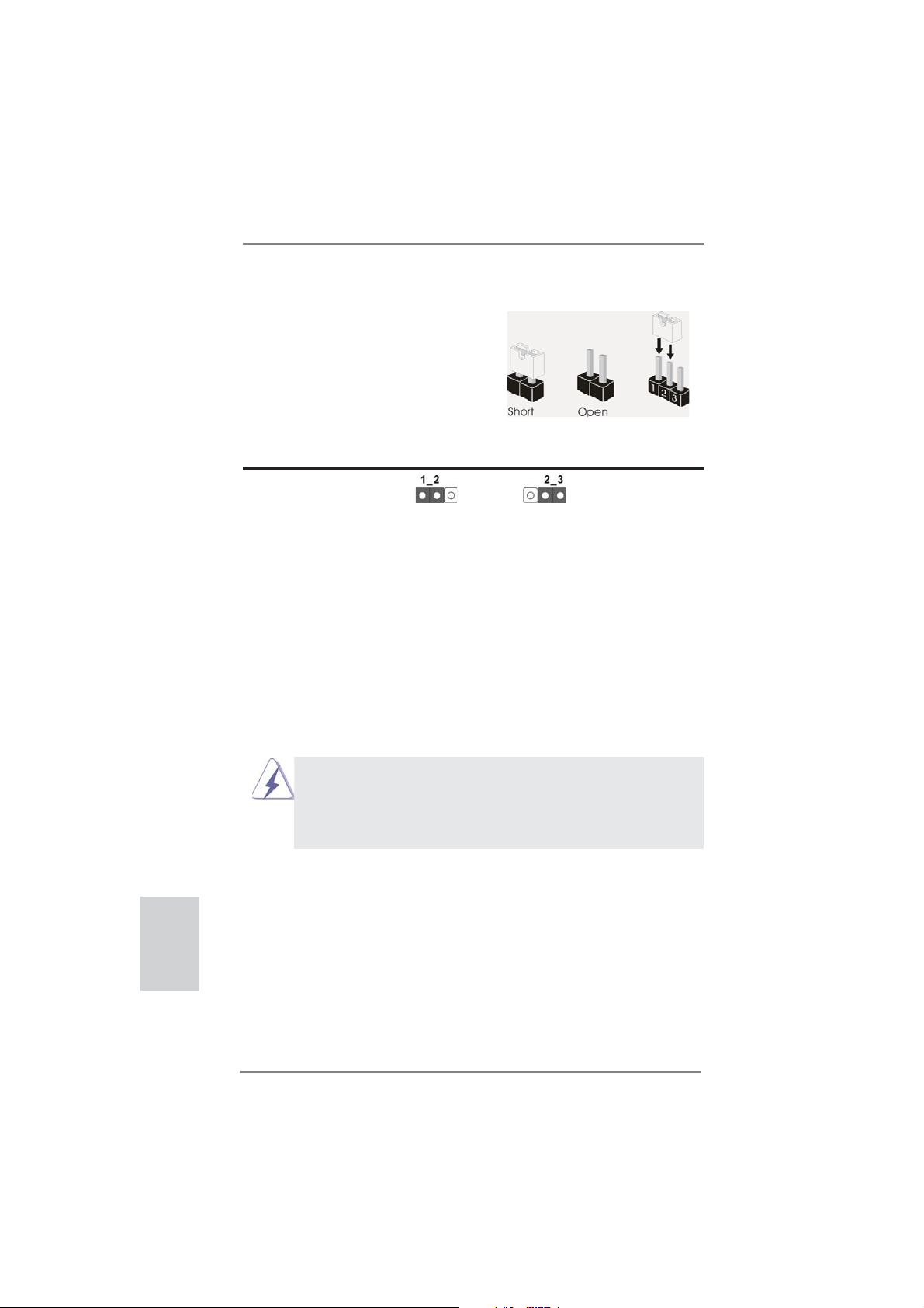
1.3 Setup de Jumpers
La ilustración muestra como los jumpers
son confi gurados. Cuando haya un jumper-
cap sobre los pins, se dice gue el jumper
está “Short”. No habiendo jumper cap sobre
los pins, el jumper está “Open”. La ilustración muesta un jumper de 3 pins cuyo
pin 1 y pin 2 están “Short”.
Jumper Setting
Limpiar CMOS
(CLRCMOS1, jumper de 3 pins)
(ver p.2, No. 24)
Nota:
CLRCMOS1 permite borrar los datos de la memoria CMOS. Para borrar los
parámetros del sistema y restablecer la confi guración predeterminada de los mismos,
apague el equipo y desenchufe el cable de alimentación de la toma de corriente
eléctrica. Deje que transcurran 15 segundos y, después, utilice un puente
cortocircuitar los contactos 2 y 3 de CLRCMOS1 durante 5 segundos. No borre
la memoria CMOS justamente después de actualizar el BIOS. Si necesita borrar
la memoria CMOS justamente después de actualizar el BIOS, debe iniciar primero
el sistema y, a continuación, cerrarlo antes de llevar a cabo el borrado de
dicha memoria. Tenga en cuenta que la contraseña, la fecha, la hora, el perfi l
predeterminado del usuario, el GUID 1394 y la dirección MAC solamente se
borrará si la batería CMOS se quita.
Valor predeterminado
Restablecimiento de
la CMOS
para
Español
80
1. El conmutador Borrar CMOS tiene la misma función que el puente
Borrar CMOS.
2. Si borra la memoria CMOS, se puede detectar un caso de abertura.
Ajuste la opción del BIOS “Clear Status” (Borrar estado) para borrar
elregistro del estado de intrusión anterior del chasis.
ASRock FM2A85X Extreme6 Motherboard
Page 81

1.4 Cabezales y Conectores en Placas
Los conectores y cabezales en placa NO son puentes. NO coloque
las cubiertas de los puentes sobre estos cabezales y conectores. El
colocar cubiertas de puentes sobre los conectores y cabezales provocará un daño permanente en la placa base.
Conexiones de serie ATA3 Estas siete conexiones de
(SATA3_1_2: vea p.2, N. 12)
(SATA3_3_4: vea p.2, N. 13)
(SATA3_7_8: vea p.2, N. 14)
(SATA3_5: vea p.2, N. 15)
una velocidad de transferencia
de 6.0 Gb/s.
serie ATA3 (SATA3) admiten
cables SATA para dispositivos
de almacenamiento internos. La
interfaz SATA3 actual permite
SATA3_8 SATA3_4 SATA3_2
SATA3_5
SATA3_7 SATA3_3 SATA3_1
Cable de datos de Cualquier extremo del cable de
serie ATA (SATA) los datos de SATA puede ser
(Opcional)
conectado con el disco duro
de SATA3 o el conectador de
SATA3 en esta placa base.
Cabezal USB 2.0 Además de dos puertos
(9-pin USB_0_1)
(vea p.2, N. 26)
USB 2.0 predeterminados en el
panel de E/S, hay tres bases
de conexiones USB 2.0 en
esta placa base. Cada una de
estas bases de conexiones
(9-pin USB_2_3)
(vea p.2, N. 27)
(9-pin USB_4_5)
(vea p.2, N. 28)
admite dos puertos USB 2.0.
USB_PWR
1
USB_PWR
USB_PWR
1
USB_PWR
P-1
P+1
GND
DUMMY
GND
P+0
P-0
P-3
P+3
GND
DUMMY
GND
P+2
P-2
Español
ASRock FM2A85X Extreme6 Motherboard
81
Page 82

Cabezal USB 3.0 Además de cuatro puertos 3.0
(19-pin USB3_5_6)
(vea p.2, N. 10)
cabecera USB 3.0 en esta
placa base. Esta cabecera USB
3.0 admiten dos puertos USB
3.0.
predeterminados situados en el
panel E/S, encontrará una
Vbus
IntA_P5_SSRX-
IntA_P5_SSRX+
GND
IntA_P5_SSTX-
IntA_P5_SSTX+
GND
IntA_P5_D-
IntA_P5_D+
VbusVbus
IntA_P6_SSRX-
IntA_P6_SSRX+
GND
IntA_P6_SSTX-
IntA_P6_SSTX+
GND
IntA_P6_D-
IntA_P6_D+
DUMMY
Español
82
Cabezal de Módulo Infrarrojos Este cabezal soporta un
(5-pin IR1)
módulo infrarrojos de
(vea p.2, N. 23)
transmisión y recepción
wireless opcional.
IRTX
+5VSB
DUMMY
1
GND
IRRX
Base de conexiones del módulo de Esta base de conexiones se
infrarrojos para el consumidor puede utilizar para conectar
(4-pin CIR1)
(vea p.2, N. 29)
Conector de audio de Este es una interface para
panel frontal cable de audio de panel frontal
(9-pin HD_AUDIO1)
(vea p.2, N. 33)
Audio.
1. El Audio de Alta Defi nición soporta la detección de conector, pero
el cable de panel en el chasis debe soportar HDA para operar
correctamente. Por favor, siga las instrucciones en nuestro manual y
en el manual de chasis para instalar su sistema.
2. Si utiliza el panel de sonido AC’97, instálelo en la cabecera de sonido
del panel frontal de la siguiente manera:
A. Conecte Mic_IN (MIC) a MIC2_L.
B. Conecte Audio_R (RIN) a OUT2_R y Audio_L (LIN) en OUT2_L.
C. Conecte Ground (GND) a Ground (GND).
E. Activación del micrófono frontal.
En sistemas operativos Windows
VistaTM 64-bit:
Acceda a la fi cha “FrontMic” (Micrófono frontal) del panel de control
Realtek. Ajuste la posición del control deslizante “Recording Volume”
(Volumen de grabación).
receptor remoto.
GND
PRESENCE#
MIC_RET
OUT_RET
que permite conexión y control
conveniente de apparatos de
D. MIC_RET y OUT_RET son sólo para el panel de sonido HD. No
necesitará conectarlos al panel de sonido AC’97.
1
MIC2_R
MIC2_L
J_SENSE
OUT2_R
OUT2_L
®
8 / 8 64-bit / 7 / 7 64-bit / VistaTM /
ASRock FM2A85X Extreme6 Motherboard
Page 83

Cabezal de panel de sistema Este cabezar acomoda varias
(9-pin PANEL1)
(vea p.2, N. 17)
Conecte el interruptor de alimentación, el interruptor de restablecimiento
y el indicador de estado del sistema situados en el chasis con esta
cabecera en función de las siguientes asignaciones de contacto. Preste
atención a los contactos positivos y negativos antes de conectar los
cables.
PWRBTN (interruptor de alimentación):
RESTABLECER (interruptor de restablecimiento):
PLED (LED de alimentación del sistema):
HDLED (LED de actividad del disco duro):
dunciones de panel frontal de
sistema.
Conecte el interruptor de encendido situado en el panel frontal del
chasis. Puede confi gurar la forma de apagar su sistema mediante el
interruptor de alimentación.
Conecte el interruptor de restablecimiento situado en el panel frontal del
chasis. Pulse el interruptor de restablecimiento para restablecer el
equipo si se bloquea y no se reinicia con normalidad.
Conecte el indicador de estado de alimentación situado en el panel
frontal del chasis. El LED se enciende cuando el sistema esté en
funcionamiento. El LED parpadea cuando el sistema se encuentre en
estado de suspensión S1. El LED se apaga cuando el sistema se
encuentre en estado de suspensión S3/S4 o se apaga (S5).
Conecte el LED de actividad de disco duro situado en el panel frontal
del chasis. El LED se enciende cuando el disco duro esté leyendo o
escribiendo datos.
Es posible que el diseño del panel frontal varíe en función del chasis. Un
módulo del panel frontal consiste principalmente de interruptor de
alimentación, interruptor de restablecimiento, LED de alimentación, LED
de actividad del disco duro, altavoz, etc. Al conectar el módulo del panel
frontal del chasis a esta cabecera, asegúrese de que las asignaciones
de cables y las asignaciones de contactos coincidan correctamente.
ASRock FM2A85X Extreme6 Motherboard
Español
83
Page 84

Cabezal del altavoz del chasis Conecte el altavoz del chasis a
(4-pin SPEAKER1)
(vea p.2, N. 21)
su cabezal.
Cabecera de indicador LED de encendido Conecte el indicador LED de
(3-pin PLED1)
(vea p.2, N. 16)
estado de encendido del
encendido del chasis a esta
cabecera para conocer el
1
PLED+
PLED+
PLED-
sistema. El indicador LED se
encenderá si el sistema se
encuentra en funcionamiento.
El indicador LED parpadeará
en el estado S1. El indicador
LED se apagará en los estados
S3/S4 o S5 (apagado).
Español
Conectores de ventilador de chasis
y alimentación
(4-pin CHA_FAN1)
(vea p.2, N. 22)
Por favor, conecte los cables
del ventilador a los conectores
de ventilador, haciendo coincidir
el cable negro con la patilla de
masa.
(3-pin CHA_FAN2)
(vea p.2, N. 41)
(3-pin CHA_FAN3)
(vea p.2, N. 43)
(3-pin PWR_FAN1)
(vea p.2, N. 4)
Conector del ventilador Conecte el cable del ventilador
de la CPU de la CPU a este conector y
(4-pin CPU_FAN1)
(vea p.2, N. 5)
FAN_SPEED_CONTROL
CPU_FAN_SPEED
+12V
haga coincidir el cable negro
con el conector de tierra.
GND
1 2 3 4
84
ASRock FM2A85X Extreme6 Motherboard
Page 85

Aunque esta placa base proporciona compatibilidad para un ventilador
(silencioso) de procesador de 4 contactos, el ventilador de procesador
de 3 contactos seguirá funcionando correctamente incluso sin la función
de control de velocidad del ventilador. Si pretende enchufar el ventilador
de procesador de 3 contactos en el conector del ventilador de
procesador de esta placa base, conéctelo al contacto 1-3.
Contacto 1-3 conectado
Instalación del ventilador de 3 contactos
(3-pin CPU_FAN2)
(vea p.2, N. 6)
Cabezal de alimentación ATX Conecte la fuente de
(24-pin ATXPWR1)
(vea p.2, N. 9)
A pesar de que esta placa base incluye in conector
de alimentación ATX de 24 pins, ésta puede funcionar
GND
+12V
CPU_FAN_SPEED
12 124
alimentación ATX a su cabezal.
13
12
24
incluso si utiliza una fuente de alimentación ATX de
20 pins tradicional. Para usar una fuente de
alimentación ATX de 20 pins, por favor, conecte su
fuente de alimentación usando los Pins 1 y 13.
Instalación de una Fuente de Alimentación ATX de 20 Pins
1
13
Conector de ATX 12V power Tenga en cuenta que es
(8-pin ATX12V1)
(vea p.2, N. 1)
corriente con el enchufe ATX
necesario conectar este
conector a una toma de
4 8
1 5
12V, de modo que proporcione
sufi ciente electricidad. De lo
contrario no se podrá encender.
Aunque esta placa base proporciona un conector de energía de 8-pin ATX 12V,
puede todavía trabajar si usted adopta un fuente tradicional de energía de 4-pin
ATX 12V. Para usar el fuente de energía de 4-pin ATX 12V, por favor conecte
su fuente de energía junto con Pin 1 y Pin 5.
Instalación de Fuente de Energía de 4-Pin ATX 12V
4 8
1 5
ASRock FM2A85X Extreme6 Motherboard
Español
85
Page 86

Cabezal del puerto COM Este cabezal del puerto COM
(9-pin COM1)
(vea p.2, N. 31)
se utiliza para admitir un
módulo de puerto COM.
Cabecera HDMI_SPDIF Cabecera HDMI_SPDIF. Ofrece
(HDMI_SPDIF1 de 2 pin)
(vea p.2, N. 32)
una salida SPDIF la tarjeta
VGA HDMI, permite al sistema
conectarse a dispositivos de
TV Digital HDMI / proyectores /
Dispositivos LCD. Conecte el
conector HDMI_SPDIF de la
tarjeta VGA HDMI a esta
cabecera.
Conector de detección de intrusión en el chasis Esta placa base admite la
(2-pin CI1)
función de control de
(vea p.2, N. 30)
APERTURA DE CARCASA,
quepermite detectar si se
1
Signal
GND
haretirado la cubierta del
chasis.Dicha función requiere
unchasis con diseño
específi copara la detección de
intrusiónen el chasis.
Español
86
Conector de alimentación XFire
(4-pin CROSS_FIRE_PWR1)
(vea p.2, N. 42)
CROSS_FIRE_PWR1
ASRock FM2A85X Extreme6 Motherboard
No es necesario utilizar este
conector. Conéctelo al conector
de alimentación del disco duro
cuando se conecten dos tarjetas
gráfi cas a esta placa base al
mismo tiempo.
Page 87

1.5 Conmutadores rápidos
Esta placa base dispone de tres conmutadores rápidos: conmutador de encendido, conmutador de reinicio y conmutador de borrado de memoria CMOS. Dichos
conmutadores permiten al usuario encender / apagar o reiniciar el sistema, o bien
borrar el contenido de la memoria CMOS.
Conmutador de encendido
(PWRBTN)
(vea p.2, N. 18)
Conmutador de reinicio
(RSTBTN)
(vea p.2, N. 20)
Conmutador de borrado de memoria CMOS
(CLRCBTN)
(vea p.3, N. 14)
El conmutador de reinicio es un
conmutador rápido que permite
al usuario reiniciar rápidamente
el sistema.
El conmutador de borrado de
memoria CMOS es un
conmutador rápido que permite
al usuario borrar rápidamente el
contenido de la memoria CMOS.
El conmutador de encendido es
un conmutador rápido que
permite al usuario encender /
apagar rápidamente el sistema.
ASRock FM2A85X Extreme6 Motherboard
Español
87
Page 88

2. BIOS Información
El Flash Memory de la placa madre deposita SETUP Utility. Durante el Power-Up
(POST) apriete <F2> o <Del> para entrar en la BIOS. Sí usted no oprime ninguna
tecla, el POST continúa con sus rutinas de prueba. Si usted desea entrar en la
BIOS después del POST, por favor reinicie el sistema apretando <Ctl> + <Alt> +
<Borrar>, o apretando el botón Reset en el panel del ordenador. Para información
detallada sobre como confi gurar la BIOS, por favor refi érase al Manual del Usuario
(archivo PDF) contenido en el CD.
3. Información de Software Support CD
Esta placa-base soporta diversos tipos de sistema operativo Windows®: 8 / 8 64 bits
/ 7 / 7 64 bits / VistaTM / Vista
base trae todos los drivers y programas utilitarios para instalar y confi gurar la placa-
base. Para iniciar la instalación, ponga el CD en el lector de CD y se desplegará el
Menú Principal automáticamente si «AUTORUN» está habilitado en su computadora. Si el Menú Principal no aparece automáticamente, localice y doble-pulse en el
archivo “ASSETUP.EXE” para iniciar la instalación.
TM
64 bits. El CD de instalación que acompaña la placa-
Español
88
ASRock FM2A85X Extreme6 Motherboard
Page 89

1. Введение
Благодарим вас за покупку материнской платы ASRock FM2A85X Extreme6 надежной
материнской платы, изготовленной в соответствии с постоянно предъявляемыми ASRock
жесткими требованиями к качеству. Она обеспечивает превосходную производительность
и отличается отличной конструкцией, которые отражают приверженность ASRock качеству
и долговечности.
Данное руководство по быстрой установке включает вводную информацию о материнской
плате и пошаговые инструкции по ее установке.
можно найти в руководстве пользователя на компакт-диске поддержки.
Спецификации материнской платы и программное обеспечение
BIOS иногда изменяются, поэтому содержание этого руководства
может обновляться без уведомления. В случае любых
модификаций руководства его новая версия будет размещена на
веб-сайте ASRock без специального уведомления. Кроме того,
самые свежие списки поддерживаемых модулей памяти и
процессоров можно найти на сайте ASRock.
Адрес веб-сайта ASRock http://www.asrock.com
При необходимости технической поддержки по вопросам данной
материнской платы посетите наш веб-сайт для получения
информации об используемой модели.
www.asrock.com/support/index.asp
1.1 Комплектность
Материнская плата ASRock FM2A85X Extreme6 (форм-фактор ATX)
Руководство по быстрой установке ASRock FM2A85X Extreme6
Компакт-диск поддержки ASRock FM2A85X Extreme6
4 x кабель данных Serial ATA (SATA) (дополнительно)
1 x I/O Щит Группы ввода / вывода
Более подробные сведения о плате
ASRock напоминает...
Для обеспечения максимальной производительности ОС Windows®
8 / 8 64-bit / 7 / 7 64-bit / Vista
BIOS выбрать для параметра Storage Confi guration (Конфигурация
запоминающего устройства) режим AHCI. Подробные сведения о
настройке BIOS см. в руководстве пользователя на прилагаемом
компакт-диске.
TM
/ VistaTM 64-bit рекомендуется в
ASRock FM2A85X Extreme6 Motherboard
Русский
89
Page 90

Русский
1.2 Спецификации
Платформа - форм-фактор ATX
- Дизайн конденсатора Premium Gold (100% японские
высококачественные конденсаторы на основе проводящих
полимеров)
Процессор - Поддерживаются процессоры для гнезда Socket FM2 с
потребляемой мощностью до 100 Вт
- Дизайн системы питания DigiPower
- Технология 8 + 2 Power Phase Design
- Поддержка технологии AMD Cool ‘n’ Quiet
- UMI-Link GEN2
Набор микросхем - AMD A85X (Hudson-D4)
Память - Поддержка технологии Dual Channel DDR3 Memory Technology
(см. ОСТОРОЖНО, пункт 1)
- 4 x гнезда DDR3 DIMM
- Поддержите DDR3 2600+(OC)/2400(OC)/2133(OC)/1866/1600/1333/
1066/800 не- ECC, безбуферная память
- Mакс. 64 Гб
- поддержка профиля Intel
- поддержка профиля AMD Memory Profi le (AMP)
Гнезда - 3 x слота PCI Express 2.0 x16 (PCIE2/PCIE4: одна видеокарта в
расширения режиме x16 (PCIE2) / x8 (PCIE4) или две видеокарты в режиме
x8 (PCIE2) / x8 (PCIE4); PCIE5: режим x4)
- 2 x гнезда PCI Express 2.0 x1
- 2 x гнезда PCI
- Поддерживаются режимы AMD Quad CrossFireX
CrossFireXTM, CrossFireXTM и двойные видеокарты
Графика - Видеоадаптер AMD Radeon HD 7000
- Поддержка DirectX 11, Pixel Shader 5.0
- Макс. объем разделяемой памяти 2GB
- четыре VGA-выхода: D-Sub, DVI-D, HDMI и DisplayPort
- Поддержка HDMI 1.4a с максимальным разрешением до 1920х1200
@ 60 Гц
- Поддержка Dual-link DVI с максимальным разрешением до
2560х1600 @ 75 Гц
- Поддержка D-Sub с максимальным разрешением до 1920х1600 @
60 Гц
- Поддержка DisplayPort 1.2 с максимальным разрешением до
4096х2160 @ 30 Гц
- Поддержка DP++
- Поддержка Multi-Streaming
- Поддержка Auto Lip Sync, Deep Color (12 бит
xvYCC и HBR (High Bit Rate Audio) через HDMI (необходим
монитор с разъемом HDMI)
- Поддержка стандарта Blu-ray Stereoscopic 3D со спецификацией
HDMI 1.4a
®
Extreme Memory Profi le (XMP)1.3/1.2
TM
TM
, 3-Way
на цветовой канал),
90
ASRock FM2A85X Extreme6 Motherboard
Page 91

- Поддержка технологии AMD Steady VideoTM 2.0: новая функция
постобработки видеоизображения для автоматического устранения
дрожания при просмотре домашних и онлайновых видеозаписей
- Поддержка функции HDCP через разъемы DVI, HDMI и DisplayPort
- Подержат Blu-луч 1080p (КОММУТАЦИОННАЯ ДОСКА) /
воспроизведение HD-DVD через разъемы DVI, HDMI и DisplayPort
Аудиосистема - 7.1 CH HD Аудио HD с Довольной Защитой
(Кодер-декодер Аудио Realtek ALC898)
- Поддержка Premium Blu-ray audio
- Поддержка технологии THX TruStudio
ЛВС - PCIE x 1 Gigabit LAN 10/100/1000 Mb/s
- Realtek RTL8111E
- поддержка Wake-On-LAN
- Поддержка определения кабеля ЛВС
- Поддержка энергосберегающего интерфейса Ethernet 802.3az
- Поддержка PXE
Разъемы ввода- I/O Panel
вывода на задней - 1 x порт мыши/клавиатуры PS/2
панели - 1 x D-Sub порт
- 1 x DVI-D порт
- 1 x HDMI порт
- 1 x DisplayPort
- 1 x порт Optical SPDIF Out
- 2 x порта USB 2.0 на задней панели в стандартной
конфигурации
- 1 x eSATA3 порт
- 4 x порта USB 3.0 на задней панели в стандартной
конфигурации
- Разъем 1 x RJ-45 LAN с светодиодным индикатором (индикатор
ACT/LINK и
- 1 x кнопка Clear CMOS
- Соединитель звуковой подсистемы: тыльная колонка / центральная
/ субвуфер / линейный вход / передняя колонка / микрофон
SATA 3 - 7 x разъема SATA3 6,0 Гбит/с, поддержка функций RAID (RAID 0,
RAID 1, RAID 5 и RAID 10), NCQ, AHCI и «горячего подключения»
USB 3.0 - 2 x задних порта USB 3.0 на контроллере AMD A85X (Hudson-D4)
с поддержкой интерфейсов USB 1.1/2.0/3.0 и скорости передачи
данных до 5 Гбит/с
- 2 x задних порта USB 3.0 на контроллере ASMedia ASM1042 с
поддержкой интерфейсов USB 1.1/2.0/3.0 и
данных до 5 Гбит/с
- 1 x передний разъем USB 3.0 (поддерживает 2 порта USB 3.0) на
контроллере AMD A85X (Hudson-D4) с поддержкой интерфейсов
USB 1.1/2.0/3.0 и скорости передачи данных до 5 Гбит/с
Колодки и - 7 x разъема SATA3 6,0 Гбит/с
плате - 1 x Колодка инфракрасного модуля
- 1 x
индикатор SPEED)
Датчик пользовательского инфракрасного модуля
TM
скорости передачи
Русский
ASRock FM2A85X Extreme6 Motherboard
91
Page 92

Русский
- 1 x Колодка COM
- 1 x Колодка HDMI_SPDIF
- 1 x разъем Power LED
- 1 x разъем датчика открытой крышки
- 2 x соединитель CPU FAN (1 x 4-контактный, 1 x 3-контактный)
- 3 x соединитель Chassis FAN (1 x 4-контактный, 2 x 3-контактный)
- 1 x соединитель Power FAN (3-контактный)
- 24-контактный Колодка питания ATX
- 8-контактный Разъем ATX 12 В
- Разъем питания XFire
- Аудиоразъем передней панели
- 3 x Колодка USB 2.0 (одна колодка для поддержки 6
дополнительных портов USB 2.0
- 1 x Колодка USB 3.0 (одна колодка для поддержки 2
дополнительных портов USB 3.0)
- 1 x Dr. Debug (7-сегментный ЖК-дисплей)
- 1 x кнопка Power Switch со светодиодом
- 1 x кнопка Reset Switch со светодиодом
BIOS - 64Mb AMI UEFI Legal BIOS с поддержкой rpaфичеckoro интеpфeйca
поль зователя
- поддержка “Plug and Play”
- ACPI 1.1, включение по событиям
- поддержка режима настройки без перемычек
- поддержка SMBIOS 2.3.1
- Регулировка напряжений DRAM, APU PCIE VDDP, CPU и CPU
NB/GFX
Компактдиск - Драйверы, Утилиты, Антивирус (пробная версия), Пробная версия
поддержки программы CyberLink MediaEspresso 6.5, Google Chrome Browser и
Toolbar
Контроль - Датчики температуры процессора
оборудо- - Датчики температуры
вания - Тахометры вентиляторов CPU/Chassis/Power FAN
- Бесшумный вентилятор ЦП блока
- Мультиконтроль скорости вентилятора ЦП/Шасси
- Определение открытой крышки
- Контроль напряжения: +12V, +5V, +3.3V, Vcore
Операцион - Совместимость с Microsoft
Vista
ные системы - FCC, CE, WHQL
Сертификаты - Совместимость с ErP/EuP Ready (требуется блок питания
совместимый с ErP/EuP)
* Для детальной информации продукта, пожалуйста посетите наш вебсайт:
http://www.asrock.com
TM
/ Поддержка 64-разрядной версии VistaTM
корпуса
®
Windows® 8 / 8 64-bit / 7 / 7 64-bit /
92
ASRock FM2A85X Extreme6 Motherboard
Page 93

1.3 Установка перемычек
Конфигурация перемычек иллюстрируется
на рисунке. Когда перемычка надета на
контакты, они называются “замкнутыми”
(short). Если на контактах перемычки нет,
то они называются “разомкнутыми” (open).
На иллюстрации показана 3-контактная
перемычка, у которой контакты 1 и 2
замкнуты.
Перемычка Установка Описание
Очистка CMOS
(CLRCMOS1,
3-контактная перемычка)
(см. стр. 2, п. 24)
Стандартные Очистка CMOS
Примечание.
Контактная колодка CLRCMOS1 позволяет очистить данные CMOS. Для
очистки данных и восстановления заводских системных параметров сначала
выключите компьютер и отсоедините сетевую вилку кабеля питания от
электророзетки. Выждите не менее 15 секунд и колпачковой перемычкой на 5
секунд перемкните штырьки 2 и 3 контактной колодки CLRCMOS1. Однако не
производите очистку CMOS непосредственно после обновления BIOS. Если
необходимо очистить CMOS сразу же после
перед очисткой CMOS, необходимо сначала выполнить загрузку системы, а
затем завершить ее работу. Примите во внимание, что пароль, дата, время,
профиль пользователя по умолчанию, идентификатор 1394 GUID и MAC-адрес
будут очищены только тогда, когда будет извлечена из своего гнезда батарейка
CMOS.
1. Переключатель Clear CMOS работает так же, как перемычка
Clear CMOS.
2. Очистка CMOS может вызвать срабатывание датчика открытой
крышки. Измените опцию «Clear Status» в BIOS, чтобы очистить
записи о предыдущих срабатываниях датчика.
окончания обновления BIOS, то,
Русский
ASRock FM2A85X Extreme6 Motherboard
93
Page 94

1.4 Колодки и разъемы на плате
Имеющиеся на плате колодки и разъемы НЕ ЯВЛЯЮТСЯ
контактами для перемычек. НЕ УСТАНАВЛИВАЙТЕ перемычки
на эти колодки и разъемы – это приведет к необратимому
повреждению материнской платы!
Разъемы Serial ATA3 семь соединителя Serial ATA3
(SATA3_1_2, см. стр. 2, п. 12)
(SATA3_3_4, см. стр. 2, п. 13)
(SATA3_7_8, см. стр. 2, п. 14)
(SATA3_5, см. стр. 2, п. 15)
кабелей SATA3. В настоящее
время интерфейс SATA
допускает скорость передачи
данных до \ 6,0 Гбит/с.
Информационный Информационный кабель
кабель Serial ATA (SATA) интерфейса SATA3 не является
(дополнительно)
направленным. Любой из его
соединителей может быть
подключен либо к жесткому
диску интерфейса SATA3 либо к
материнской плате.
предназначаются для
подключения внутренних
устройств хранения с
использованием нтерфейсных
SATA3_8 SATA3_4 SATA3_2
SATA3_5
SATA3_7 SATA3_3 SATA3_1
Русский
Колодка USB 2.0 Помимо два стандартных
(9-контактный USB_0_1)
(см. стр. 2, п. 26)
портов USB 2.0 на панели ввода-
вывода, на данной материнской
плате предусмотрено три разъема
USB 2.0. Каждый разъем USB 2.0
поддерживает два порта USB 2.0.
(9-контактный USB_2_3)
(см. стр. 2, п. 27)
(9-контактный USB_4_5)
(см. стр. 2, п. 28)
USB_PWR
1
USB_PWR
USB_PWR
1
USB_PWR
P-1
P+1
GND
DUMMY
GND
P+0
P-0
P-3
P+3
GND
DUMMY
GND
P+2
P-2
94
ASRock FM2A85X Extreme6 Motherboard
Page 95

Колодка USB 3.0 Помимо четыре стандартных
(19-контактный USB3_5_6)
(см. стр. 2, п. 10)
плате предусмотрен один разъем
USB 3.0. Этот разъем USB 3.0
поддерживает два порта USB 3.0.
портов USB 3.0 на панели ввода-
Vbus
IntA_P5_SSRX-
IntA_P5_SSRX+
GND
IntA_P5_SSTX-
IntA_P5_SSTX+
GND
IntA_P5_D-
IntA_P5_D+
VbusVbus
IntA_P6_SSRX-
IntA_P6_SSRX+
GND
IntA_P6_SSTX-
IntA_P6_SSTX+
GND
IntA_P6_D-
IntA_P6_D+
DUMMY
вывода, на данной материнской
Колодка инфракрасного модуля Данная колодка позволяет
(5-контактный IR1)
(см. стр. 2, п. 23)
подключить дополнительный
модуль беспроводного
инфракрасного
приемопередатчика.
IRTX
+5VSB
DUMMY
1
GND
IRRX
Датчик пользовательского инфракрасного модуля Датчик можно использовать для
(4-контактный CIR1)
(см. стр. 2, п. 29)
Аудиоразъем передней Этот интерфейс предназначен
панели для присоединения
(9-контактный HD_AUDIO1)
(см. cтр. 2, п.33)
подключение аудиоустройств и
управление ими.
подключения дистанционный
приемник.
GND
PRESENCE#
MIC_RET
MIC2_R
MIC2_L
J_SENSE
OUT2_R
OUT_RET
OUT2_L
аудиокабеля передней панели,
обеспечивающего удобное
1
1. Система High Defi nition Audio поддерживает функцию
автоматического обнаружения разъемов (Jack Sensing), однако
для ее правильной pаботы кабель панели в корпусе должен
поддерживать HDA. При сборке системы следуйте инструкциям,
приведенным в нашем руководстве и руководстве пользователя
для корпуса.
2. Если вы используете аудиопанель AC’97, подключите ее к колодке
аудиоинтерфейса передней панели следующим образом:
A. Подключите
выводы Mic_IN (MIC) к контактам MIC2_L.
B. Подключите выводы Audio_R (RIN) к контактам OUT2_R, а
выводы Audio_L (LIN) к контактам OUT2_L.
C. Подключите выводы Ground (GND) к контактам Ground (GND).
D. Контакты MIC_RET и OUT_RET предназначены только для
аудиопанели HD. При использовании аудиопанели AC’97
подключать их не нужно.
E. Процедура активации микрофона приведена ниже.
Русский
ASRock FM2A85X Extreme6 Motherboard
95
Page 96

Русский
Для ОС Windows® 8 / 8 64-бита / 7 / 7 64-бита, VistaTM / VistaTM
64-бита:
Перейдите к вкладке «FrontMic» (Передний микрофон) в панели
управления Realtek. Отрегулируйте уровень «Recording
Volume» (Громкость записи).
Колодка системной панели Данная колодка обеспечивает
(9-контактный PANEL1)
(см. стр. 2, п. 17)
Подключите к этому разъему кнопку питания, кнопку сброса
и индикатор состояния системы на корпусе в соответствии с
указанным ниже назначением контактов. При подключении кабелей
необходимо соблюдать полярность положительных и отрицательных
контактов.
PWRBTN (кнопка питания):
Подключите к этим контактам кнопку питания на передней панели
корпуса. Способ выключения системы
можно настроить.
RESET (кнопка сброса):
Подключите к этим контактам кнопку сброса на передней панели
корпуса. Нажмите кнопку сброса для перезагрузки компьютера, если
компьютер «завис» и нормальную перезагрузку выполнить не
удается.
PLED (индикатор питания системы):
Подключите к этим контактам индикатор состояния питания на
передней панели
работает. Индикатор мигает, когда система находится в режиме
ожидания S1. Этот индикатор не светится, когда система находится
в режиме ожидания S3 или S4, либо выключена (S5).
HDLED (индикатор активности жесткого диска):
Подключите к этим контактам индикатор активности жесткого диска
на передней панели корпуса. Этот индикатор светится,
осуществляется считывание или запись данных на жестком диске.
работу нескольких функций
передней панели системы.
с помощью кнопки питания
корпуса. Этот индикатор светится, когда система
когда
Конструкция передней панели может различаться в зависимости от
корпуса. Модуль передней панели в основном состоит из кнопки
питания, кнопки сброса, индикатора питания, индикатора активности
жесткого диска, динамика и т.п. При подключении к этому разъему
модуля передней панели корпуса
подключаются к соответствующим контактам.
удостоверьтесь, что провода
96
ASRock FM2A85X Extreme6 Motherboard
Page 97

Колодка динамика корпуса Подключите к этой колодке
(4-контактный SPEAKER1)
(см. стр. 2, п. 21)
кабель от динамика на корпусе
компьютера.
разъем Power LED Подключите индикатор Power LED
(3-контактный PLED1)
(см. стр. 2, п. 16)
светодиод продолжит мигать в
к этому разъему для отображения
статуса питания системы. Этот
1
PLED+
PLED+
PLED-
режиме S1. Светодиод будет
выключен в режимах S3/S4 или
S5 (система выключена).
Chassis и Power Fan-соединители
(4-контактный CHA_FAN1)
(см. стр. 2, п. 22)
Подключите кабели вентилятора
к соединителям и присоедините
черный шнур к штырю
заземления.
(3-контактный CHA_FAN2)
(см. стр. 2, п. 41)
(3-контактный CHA_FAN3)
(см. стр. 2, п. 43)
(3-контактный PWR_FAN1)
(см. стр. 2, п. 4)
Разъем вентилятора Подключите к этому разъему
процессора кабель вентилятора процессора
(4-контактный CPU_FAN1)
(см. стр. 2, п. 5)
соответствовал контакту земли.
FAN_SPEED_CONTROL
CPU_FAN_SPEED
так, чтобы черный провод
+12V
GND
1 2 3 4
Данная материнская плата поддерживает вентиляторы процессора
с 4-контактным разъемом (функция тихого режима вентилятора),
однако вентиляторы с 3-контактным разъемом также будут успешно
работать, хотя функция управления скоростью вращения
вентилятора окажется недоступной. Если вы хотите подключить
вентилятор процессора с 3-контактным разъемом к разъему
вентилятора процессора на данной материнской плате,
для этого
следует использовать контакты 1-3.
Контакты 1-3 подключены
Установка вентилятора с 3-контактным разъемом
Русский
ASRock FM2A85X Extreme6 Motherboard
97
Page 98

(3-контактный CPU_FAN2)
(см. стр. 2, п. 6)
GND
+12V
CPU_FAN_SPEED
Колодка питания ATX Подключите к этой колодке
(24-контактный ATXPWR1)
(см. стр. 2, п. 9)
кабель питания ATX.
Несмотря на то, что эта материнская плата предусматр-
ивает 24-штыревой разъем питания ATX, работа будет
12 124
13
12
продолжаться, даже если адаптируется традиционный
20-штыревой разъем питания ATX. Для использования
20-штыревого разъема питания ATX вставьте источник
питания вместе со штекером 1 и штекером 13.
Установка 20-штыревого разъема питания ATX
1
Колодка питания 12V-ATX Обратите внимание, что к этому
(8-контактный ATX12V1)
(см. стр. 2, п. 1)
разъему необходимо
подключить вилку блока питания
ATX 12 В, чтобы обеспечить
4 8
1 5
достаточную мощность
электропитания. В противном
случае включение системы будет
невозможно.
Хотя эта объединительная плата обеспечивает ATX с 8 булавками 12V
соединитель власти, это может все еще работать, если Вы принимаете
традиционный ATX с 4-Pin 12V электропитание. Чтобы использовать
электропитание ATX с 4-Pin, пожалуйста включите ваше электропитание
наряду с Булавкой 1 и Прикрепите 5.
4 8
24
13
Русский
ATX С 4-Pin 12V Установка Электропитания
1 5
Колодка COM-порта Данная колодка COM-порта
(9-контактный COM1)
(см. стр. 2, п. 31)
позволяет подключить модуль
порта COM.
98
ASRock FM2A85X Extreme6 Motherboard
Page 99

Колодка HDMI_SPDIF Колодка HDMI_SPDIF
(2-контактный HDMI_SPDIF1)
(см. стр. 2, п. 32)
аудиосигнала на VGA-карту
обеспечивает подачу выходного
HDMI, что позволяет подключать
к системе цифровые телевизоры,
проекторы или
жидкокристаллические панели
HDMI. Соедините эту колодку с
разъемом HDMI_SPDIF на VGA карте HDMI.
Датчик открытой крышки Эта материнская плата
(2-контактный CI1)
(см. стр. 2, п. 30)
поддерживает функцию
определения открытой крышки,
1
Signal
GND
которая позволяет определить,
была ли снята крышка корпуса.
Функция требует поддержку со
стороны корпуса.
Разъем питания XFire
(4-контактный CROSS_FIRE_PWR1)
(см. стр.2 п. 42)
Данный разъем использовать не
обязательно, но его следует
подключить к разъему питания
жесткого диска, если в системную
CROSS_FIRE_PWR1
плату одновременно установлены
две видеокарты.
1.5 Быстрое переключение
На этой материнской плате есть три кнопки для ускорения работы: кнопка питания,
кнопка перезагрузки и кнопка для очистки CMOS, которые позволяют пользователям
быстро включить/выключить или перезагрузить компьютер, сбросить установки CMOS,
соответственно.
Power Switch
(PWRBTN)
(см. стр. 2, п. 18)
Reset Switch
(RSTBTN)
(см. стр. 2, п. 20)
Кнопка Power Switch позволяет
быстро включить или выключить
систему.
Кнопка Reset Switch позволяет
быстро перезагрузить систему.
Clear CMOS Switch
(CLRCBTN)
(см. стр. 3, п. 14)
Русский
Кнопка Clear CMOS Switch
позволяет быстро сбросить
установки CMOS.
99
ASRock FM2A85X Extreme6 Motherboard
Page 100

2. Информация о BIOS
Утилита настройки BIOS (BIOS Setup) хранится во флэш-памяти на материнской плате.
Чтобы войти в программу настройки BIOS Setup, при запуске компьютера нажмите <F2>
или <Del> во время самопроверки при включении питания (Power-On-Self-Test – POST).
Если этого не сделать, то процедуры тестирования POST будут продолжаться обычным
образом. Если вы захотите вызвать BIOS Setup уже после POST, перезапустите систему
с помощью клавиш <Ctrl> + <Alt> + <Delete> или нажатия кнопки сброса
системы. Подробную информацию о программе BIOS Setup вы найдете в Руководстве
пользователя (в формате PDF) на компакт-диске поддержки.
на корпусе
3. Информация о компакт-диске
поддержки с программным
обеспечением
Данная материнская плата поддерживает различные операционные системы Microsoft®
Windows®: 8 / 8 64-bit / 7 / 7 64-bit / VistaTM / VistaTM 64-bit. Поставляемый вместе с ней
компакт-диск поддержки содержит необходимые драйверы и полезные утилиты, которые
расширяют возможности материнской платы.
Чтобы начать работу с компакт-диском поддержки, вставьте его в дисковод CD-ROM.
Если в вашем компьютере включена функция автозапуска (AUTORUN), то на экране
автоматически появится главное меню компакт-диска (Main Menu). Если этого не
произошло, найдите
дважды щелкните на нем, чтобы открыть меню.
в папке BIN на компакт-диске поддержки файл ASSETUP.EXE и
Русский
100
ASRock FM2A85X Extreme6 Motherboard
 Loading...