


AMD RAID Installation Guide
1. AMD BIOS RAID Installation Guide …………………………………………………………………….. 3
1.1 Introduction to RAID ……………………………………………………………………………….. 3
1.2 RAID Configurations Precautions ………………………………………………………………… 4
1.3 Installing Windows 8 / 8 64-bit / 7 / 7 64-bit / Vista / Vista 64-bit With RAID Functions …..… 5
1.4 Opening Option ROM ………..…………………………………………………………………….. 6
1.5 Using the Main Menu ………..…………………………………………………………………….. 7
1.6 Viewing Drive Assignments ………..…………………………….……………………………...... 8
1.7 Secure Erasing a Physical Drive ………..……………………….……………………………...... 9
1.8 Creating a Logical Drive ………..…………………………………………………………….….. 11
1.9 Deleting a Logical Drive ………..……………………………………………………………..….. 16
1.10 Viewing Controller Configuration ………..…………………………………………………..….. 17
1.11 Responding to Logical Drive Problems ………..……………………………..……………..….. 18
1

2. AMD Windows RAID Installation Guide ……………………………………………………………… 19
2.1 Components of RAIDXpert Installation Software ……………………………………………. 19
2.2 Browser Support ………………………………………………………………………………… 19
2.3 Installing RAIDXpert ……………………………………………………………………………. 19
2.4 Logging into RAIDXpert ………………………………………………………………………… 22
2.5 Regular Connection……………………………………………………………………………... 22
2.6 Secure Connection………………………………………………………………………………. 22
2.7 Creating a New Logical Drive ………………………………………………………………….. 23
2.8 Connecting to RAIDXpert from the Internet ………………………………………………….. 26
2.9 Running RAIDXpert without Network Connection …………………………………………… 26
2

1. AMD BIOS RAID Installation Guide
AMD BIOS RAID Installation Guide is an instruction for you to configure RAID functions by using the Option ROM
under BIOS environment. After you make a SATA /
BIOS setup to set the option to RAID mode by following the detailed instruction of the “User Manual” in our support CD
or “Quick Installation Guide”, then you can start to use the Option ROM to configure RAID.
SATA2 driver diskette, press <F2> or <Del> to enter
1.1 Introduction to RAID
The term “RAID” stands for “Redundant Array of Independent Disks”, which is a method combining two or more hard
disk drives into one logical unit. For optimal performance, please install identical drives of the same model and
capacity when creating a RAID set.
RAID 0 (Data Striping)
RAID 0 is called data striping that optimizes two identical hard disk drives to read and write data in parallel, interleaved
stacks. It will improve data access and storage since it will double the data transfer rate of a single disk alone while the
two hard disks perform the same work as a single drive but at a sustained data transfer rate.
WARNING!!
Although RAID 0 function can improve the access performance, it does not provide any fault tolerance. Hot-Plug any HDDs of the
RAID 0 Disk will cause data damage or data loss.
RAID 1 (Data Mirroring)
RAID 1 is called data mirroring that copies and maintains an identical image of data from one drive to a second
drive. It provides data protection and increases fault tolerance to the entire system since the disk array
management software will direct all applications to the surviving drive as it contains a complete copy of the data in
the other drive if one drive fails.
RAID 10 (Stripe Mirroring)
RAID 0 drives can be mirrored using RAID 1 techniques, resulting in a RAID 10 solution for improved performance
plus resiliency. The controller combines the performance of data striping (RAID 0) and the fault tolerance of disk
mirroring (RAID 1). Data is striped across multiple drives and duplicated on another set of drives.
3

1.2 RAID Configurations Precautions
1. Please use two new drives if you are creating a RAID 0 (striping) array for performance. It is recommended
to use two SATA drives of the same size. If you use two drives of different sizes, the smaller capacity hard
disk will be the base storage size for each drive. For example, if one hard disk has an 80GB storage
capacity and the other hard disk has 60GB, the maximum storage capacity for the 80GB-drive becomes
60GB, and the total storage capacity for this RAID 0 set is 120GB.
2. You may use two new drives, or use an existing drive and a new drive to create a RAID 1 (mirroring) array
for data protection (the new drive must be of the same size or larger than the existing drive). If you use two
drives of different sizes, the smaller capacity hard disk will be the base storage size. For example, if one
hard disk has an 80GB storage capacity and the other hard disk has 60GB, the maximum storage capacity
for the RAID 1 set is 60GB.
3. Please verify the status of your hard disks before you set up your new RAID array.
WARNING!!
Please backup your data first before you create RAID functions. In the process you create RAID, the system will ask if you
want to “Clear Disk Data” or not. It is recommended to select “Yes”, and then your future data building will operate under a
clean environment.
4

1.3 Installing Windows 8 / 8 64-bit / 7 / 7 64-bit / Vista / Vista 64-bit With RAID
Functions
If you want to install Windows 8 / 8 64-bit / 7 / 7 64-bit / Vista / Vista 64-bit on a RAID disk composed of 2 or more
SATA / SATA2 HDDs with RAID functions, please follow below procedures according to the OS you install.
STEP 1: Set up UEFI.
A. Enter UEFI SETUP UTILITY → Advanced screen →Storage Configuration.
B. Set the “SATA Mode” option to [RAID].
STEP 2: Set RAID configuration.
Before you start to configure RAID function, you need to check this RAID installation guide for proper configuration.
Please refer to the BIOS RAID installation guide part in this document for details.
STEP 3: Install Windows 8 / 8 64-bit / 7 / 7 64-bit / Vista / Vista 64-bit OS on your system.
5

1.4 Opening Option ROM
The Option ROM and the Option ROM Utility are built-in components of the AMD motherboard. When the Option ROM
loads during boot-up, it displays pertinent information about the RAID logical drives that it finds.
When the Option ROM screen appears, press Ctrl-F to enter the Utility. The Option ROM screen displays the
following information:
ID – An identification number assigned to each logical drive by the Option ROM.
Mode – The RAID mode (level) configuration of the logical drive
LD Name – The name you assigned when the logical drive was created, or a default name
LD Size – The data capacity of the logical drive in GB (Gigabytes).
Status – Shows one of three logical drive conditions:
Functional – The logical drive is fully operational, and no problems are present.
Critical – The logical drive is still operational, meaning you can read and write data to it. But the logical
drive has lost fault tolerance. For RAID levels 1, 5, and 10, the logical drive contains a failed
physical drive. You must identify and replace the failed physical drive, then rebuild the logical
drive using the RAIDXpert software.
Offline – The logical drive is no longer operational, meaning you cannot read and write data to it. You
must identify and replace the failed drive(s). Then you can create a new logical drive and copy
your data to it from the last tape backup or other device.
For RAID levels 1, 5, and 10, two or more physical drives in the logical drive have failed.
For a RAID 0 or JBOD at least one physical drive has failed.
A RAID Ready logical drive disappears from the user interface when its physical drive fails.
Port – The AMD motherboard port ID number to which the Single Disk (unassigned physical drive) is
attached.
Device Name – The manufacturer’s name and model number of this physical drive. S.M.A.R.T. refers to the
Self-Monitoring, Analysis and Reporting System that monitors the condition of disk drives. Healthy means the
disk drive is OK.
6

1.5 Using the Main Menu
When the Option ROM displays on your computer screen, press Ctrl-F to enter the Utility and display the Main Menu.
The Main Menu (above) has five options:
Press 1 to view physical drive assignments
Press 2 to create a logical drive or view information about an existing logical drive.
Press 3 to delete a logical drive.
Press 4 to view the controller configuration.
Press Esc (Escape) to exit the utility and reboot your PC.
7

1.6 Viewing Drive Assignments
From the Main Menu screen, press 1 to see the View Drive Assignments screen.
This screen reports physical drive assignments and provides the following information:
Port: ID – Shows the AMD motherboard port ID number to which a particular physical drive is attached. The
total number of ports depends on the motherboard and whether a port multiplier is connected.
Drive Model – Identifies the manufacturer, model, and model number (if applicable) of each physical drive.
S.M.A.R.T. refers to the Self-Monitoring, Analysis and Reporting System that monitors the condition of disk
drives. Healthy means the disk drive is OK.
Capabilities – The type and speed of the physical drive, such as SATA 1.5 Gb/s, 3.0 Gb/s, or 6.0 Gb/s.
Capacity (GB) – Reflects the capacity in GB (gigabytes) of the physical drive.
Assignment – This field identifies the logical drive to which the physical drive belongs. In the example above,
there is one logical drive composed of two physical drives. LD 1-2 means logical drive 1, physical drive 2.
Unassigned drives are labeled Single Disk. You can use unassigned drives to create a new logical drive.
Extent – An extent is a portion of the physical drive. The Option ROM Utility allows you to split the capacity of a
physical drive between two logical drives. The portion of a physical drive available to be used in a logical drive
is called an extent. The sum of the two extents is slightly smaller than the total capacity of the physical drive.
8

1.7 Secure Erasing a Physical Drive
Warning
When you secure erase a physical drive, you permanently delete all data on the physical drive. There is
no way to restore your data after a secure erase.
Do not secure erase a physical drive that belongs to a logical drive. This action will cause the logical drive
to go Critical or Offline.
Back up any important data before you use this feature!
Important
Once you begin, you cannot exit the Option ROM Utility until the Secure Erase operation is finished. Secure Erase
takes about the same amount of time as a partition and format. Plan ahead and allow yourself enough time.
The Secure Erase feature overwrites all sectors on a physical drive. To secure erase a physical drive:
1 From the Main Menu screen, press 1 to see the View Drive Assignments screen.
2 Press the arrow keys to highlight a physical drive you want to secure erase and press Ctrl-H. The caution
screen appears.
3 Press Y to continue. The settings screen appears.
4. Optional. Press the arrow keys to highlight the settings you want. Press the Backspace key to delete, then enter
a new value for:
9

ٛ
Erase Count. The default is 1.
ٛ
Erase Pattern The default is 55AA (hexadecimal)
5 Press Ctrl-E to continue. The confirmation screen displays.
6 Press Ctrl-P to secure erase your physical drive. Watch the screen to monitor the progress.
Secure Erase runs until all sectors of the selected physical drive have been overwritten. Depending on the size of your
physical drive, this operation can take some time. You cannot exit the Option ROM Utility until the Secure Erase is
done.
10

1.8 Creating a Logical Drive
1 From the Main Menu screen, press 2 to display the Define LD Menu.
2. Press the arrow keys to highlight a logical drive number you want to define and press Enter to select it.
The Define LD Menu appears for the number you selected.
3. Choose the RAID Level you want. In the Define LD Menu section, press the Spacebar to toggle through logical
drive types:
ٛ
RAID 0 (Stripe)
ٛ
RAID 1 (Mirror)
ٛ
RAID 5 (Stripe with Distributed Parity)
ٛ
RAID 10 (Stripe/Mirror)
ٛ
RAID Ready (Single Drive)
JBOD (Just a Bunch of Disks)
4. Press the arrow keys to move to the next option. Option choices depend on the RAID level you selected.
ٛ
Initialization. Press the Spacebar to toggle through Fast, Full, and None.
ٛ
Stripe Block Size. Press the Spacebar to toggle through 64 KB, 128 KB and 256 KB.
ٛ
Gigabyte Boundary. Press the Spacebar to toggle between ON and OFF.
ٛ
Read Policy. Press the Spacebar to toggle through NA, Read Cache, and Read Ahead.
ٛ
Write Policy. Determined by the Read Policy.
11
5. Press the arrow keys to move to Disk Assignments. Press the spacebar to toggle between N and Y for each
available drive. Y means this physical drive will be assigned to the logical drive.
Assign the appropriate number of physical drives to your logical drive.
For optimal performance, assign physical drives of the same model and
capacity.
Your PC’s boot drive is not listed under Drive Assignments.
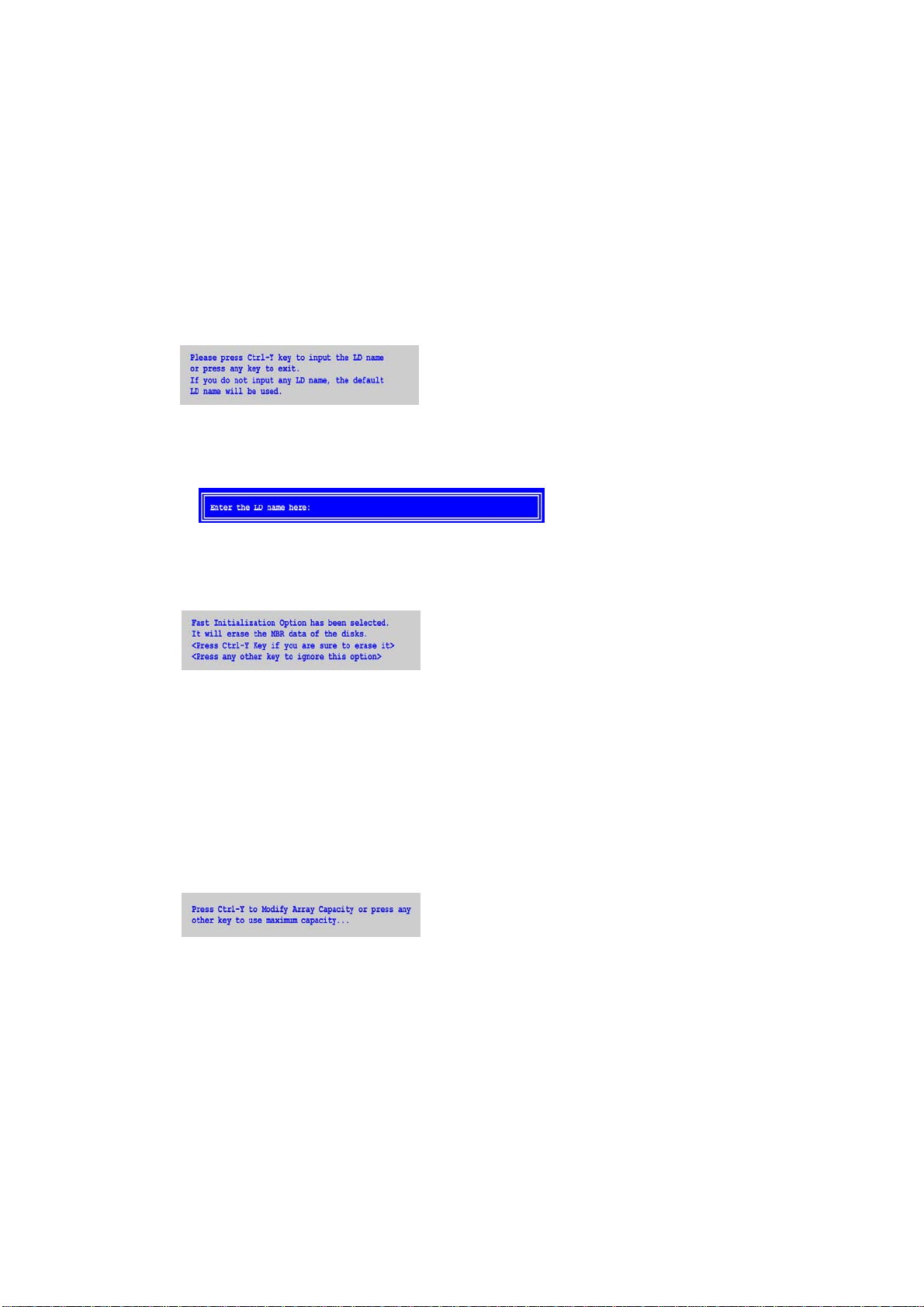
6. Press Ctrl-Y to save your logical drive configuration. The name prompt appears.
Do one of the following actions:
Press Ctrl-Y to display a name field.
Type a name in the field and press Enter.
Press any other key to use the default name, such as Logical Drive 1.
If you set Fast Initialization, the following message displays:
7. Do one of the following actions:
ٛ
Press Ctrl-Y to perform the fast initialization.
ٛ
Press any other key to cancel logical drive creation.
You have the option of using all of the physical drive capacity for one logical drive or allocating a portion to a
second logical drive.
This option is not available for JBOD or RAID Ready logical drives.
8. Choose one of the following actions:
ٛ
Allocate the full capacity of the physical drives to a single logical drive. Go to “One Logical Drive” below.
ٛ
Split the capacity of the physical drives between two logical drives.
One Logical Drive
Continued from Create Logical Drive step 8, above.
12

1 Press any key (except for Ctrl-Y) to use the full portion of the logical drive for one logical drive.
2 Press Esc to exit to the Main Menu. Press Esc again to exit the Utility.
3 Press Y to restart the computer.
You have successfully created a new RAID logical drive.
Note
You must be partition and format your new logical drive before you can use it.
Two Logical Drives
Continued from Create Logical Drive step 8, above.
1 Press Ctrl-Y to allocate a portion of the physical drives to the first logical drive.
2 Enter the desired capacity in GB for the first logical drive and press Enter. The Define LD Menu displays again.
3 Press the up and down arrow keys to select an available logical drive number and press Enter.
13

4. Choose the RAID level and options for the second logical drive. Note that the physical drives on Ports 1 and 2
reflect smaller capacities because a portion of their original capacity belongs to the first logical drive. The
physical drives on Ports 3 and 4 have not yet been assigned to a logical drive, so they show the original
capacity.
5 Press Ctrl-Y to save your logical drive configuration.
6 Press Esc to exit to the Main Menu. Press Esc again to exit the Utility.
7 Press Y to restart the computer.
You have successfully created a new RAID logical drive.
Note
You must be partition and format your new logical drive before you can use it.
Viewing Drive Assignments, Split Physical Drives
After you create two logical drives from the same set of physical drives, press 1 on the Main Menu screen to see the
View Drive Assignments screen.
In this example, observe how each of the physical drives in Ports 1and 2 are split between two logical drives. Extent 1
belongs to logical drive 1 (LD 1). Extent 2 belongs to logical drive 2 (LD 2).
Under Assignment, the physical drives are divided into LD 1 and LD 2. For example, LD 1-1 means logical drive
1, physical drive 1; and LD 1-2 means logical drive 1, physical drive 2.
14

Note that the combined size of the extents is slightly smaller than the total capacity of the physical drive.
Unassigned physical drives are labeled Single Disk. You can use an unassigned physical drive to create a new logical
drive.
15

1.9 Deleting a Logical Drive
Warning
When you delete a logical drive, you delete all data on the logical drive. Be sure to back up any important data before
you delete a logical drive!
Note
If you create a logical drive and install the OS on it, you cannot delete that logical drive.
To delete a logical drive:
1 From the Main Menu screen, press 3 to display the Delete LD Menu.
2 Highlight the logical drive you wish to delete and press the Del key or Alt-D.
The Delete LD Menu for the selected logical drive appears.
3 Press Ctrl-Y to confirm and complete logical drive deletion.
The screen returns to the Delete LD Menu. Press Esc to return to the Main Menu.
16

1.10 Viewing Controller Configuration
From the Main Menu screen, press 4 to display the Controller Configuration Options screen.
The Controller Configuration Options screen provides diagnostic information that might be helpful for troubleshooting
purposes:
The system IRQ used by the RAID controller
Base Address
17

1.11 Responding to Logical Problems
While physical drives are highly reliable, on occasion a physical drive can fail.
Fault-tolerant (RAID 1, 5, and 10) logical drives go Critical when a physical drive fails.
Non-fault-tolerant (RAID 0 and JBOD) logical drives go Offline when a physical drive fails.
A RAID Ready logical drive disappears from the user interface when its physical drive fails.
When you boot your system, the Option ROM screen informs you if there is a critical or offline logical drive.
Allow your PC to finish booting and use RAIDXpert to identify the failed drive and to rebuild your logical drive.
See the RAIDXpert User Manual for more information.
18

2. AMD Windows RAID Installation Guide
AMD Windows RAID Installation Guide is an instruction for you to configure RAID functions by using RAIDXpert RAID
management software under Windows environment. The RAIDXpert software offers local and remote management
and monitoring of all AMD SATA logical drives that exist anywhere on a network. Its browser-based GUI provides
email notification of all major events/alarms, memory cache management, drive event logging, logical drive
maintenance, rebuild, and access to all components in the RAID configuration (server, controller, logical drives,
physical drives, and enclosure). RAIDXpert is designed to work with AMD SATA RAID controllers. Other brands of
RAID controllers are not supported. Please read this guide carefully and follow the instructions below to configure and
manage RAID functions.
2.1 Components of RAIDXpert Installation Software
RAIDXpert installation software will install two major components to your system:
1. RAIDXpert RAID management software: The RAIDXpert software installs on the PC with the AMD SATA RAID
Controller (the “Host PC”).
2. Java Runtime Environment (in a private folder): The RAIDXpert installation program installs a private JRE in
folder _jvm under the same directory where RAIDXpert is installed. RAIDXpert uses this private JRE to avoid
incompatibility issues with any other JREs that may be present on your system.
2.2 Browser Support
On the Host PC with the AMD Controller, where you install RAIDXpert, you must have one of the following browsers:
Internet Explorer 6.0, Mozilla Suite 1.7, Mozilla Firefox 1.0, or Netscape Navigator 7.1.
If you do not have one of the above browsers, install the browser first and make it the default browser. Then install
RAIDXpert. You must use one of the browsers listed above on your networked PC in order to access RAIDXpert over
the network.
2.3 Installing RAIDXpert
Follow these steps to install RAIDXpert on your Windows-based PC or Server.
1. Boot the PC or server, launch Windows, and log in as the Administrator. If the computer is already running, exit
all programs. If you are not logged in as the Administrator, log out, then log in again as the Administrator.
2. Insert the software CD into your CD-ROM drive.
3. Double-click the Install CD’s icon to open it.
4. Double-click the Installer icon to launch it (right). The first RAIDXpert installation dialog box appears.
5. Follow the prompts in the installation dialog boxes.
6. When the first installation screen appears, choose an installer language from the dropdown menu.
19

7. When the Welcome screen appears, click the Next button.
8. When the License Agreement screen appears, click the “I accept the terms of the license agreement” option to
proceed with installation. Then click the Next button to continue.
Note:
If you leave the “I do not accept the terms of the license” option selected, the installation will quit when you click Next.
9. When the Choose Install Folder screen appears, make your selection of a folder for the RAIDXpert applications
you are installing. For example, the Windows default folder is: C:\Program Files\AMD\RAIDXpert
20

If you want a different folder, type its location or click the Choose... button and select a new location. Click the
Next button when you are finished.
10. When the Check HTTP SSL screen appears, you can choose External Security. An explanation follows.
External SSL Security – Applies security to all connections involving the Internet or outside your company
firewall. Security options are invisible to authorized users. AMD provides a default certificate for the server as
well as for internal data communication. However, in some cases it is better to install and verify your own
certificate for the webserver. And, if possible, verify your certificate by certificate authority like Verisign or
Thwate. See your MIS Administrator for guidance. Click the Next button when you have made your choice.
11. When the Ready to Install screen appears, click the Install button to continue.
21

12. When the Install Complete screen appears, click the Finish button.
2.4 Logging into RAIDXpert
Choose RAIDXpert in the Windows Programs menu. Or, log on manually with your browser:
1. Launch the Browser.
2. In the Browser address field, type the entry explained below.
If you did not choose the External Security option during RAIDXpert installation, use the Regular connection.
If you chose the External Security option during RAIDXpert installation, use the Secure connection.
2.5 Regular Connection
RAIDXpert uses an HTTP connection . . . . . . . . . . . . . . . . . . . .http://
• Enter the Host PC’s IP address . . . . . . . . . . . .127.0.0.1 or localhost
• Enter the Port number . . . . . . . . . . . . . . . . . . . . . . . . . . . . . . :25902
• Add to launch RAIDXpert. . . . . . . . . . . . . . . . . . . . . . . . . . . . . . /amd
Together, your entry looks like this:
http://127.0.0.1:25902/ati or http://localhost:25902/ati
2.6 Secure Connection
RAIDXpert uses a secure HTTP connection . . . . . . . . . . . . . .https://
22

• Enter the Host PC’s IP address . . . . . . . . . . . .127.0.0.1 or localhost
• Enter the Port number . . . . . . . . . . . . . . . . . . . . . . . . . . . . . . . :8443
• Add to launch RAIDXpert. . . . . . . . . . . . . . . . . . . . . . . . . . . . . . /amd
Together, your entry looks like this:
https://127.0.0.1:8443/amd or https://localhost:8443/amd
Note that the IP address shown above applies to a log-in at the Host PC. When you log in over a network, enter the
Host PC’s actual IP address or hostname.
Press the Enter key. Then, when the login screen appears, type admin in the Login ID field. Type admin again in the
Password field. The RAIDXpert login and password are case sensitive.
Click the Sign in button. After sign-in, the RAIDXpert opening screen appears.
2.7 Creating a New Logical Drive
A logical drive is a collection of physical drives in a RAID. To create a new logical drive:
1. Click Logical Drive View in Tree View.
2. Click the Create tab in Management View. The Select RAID Level screen appears.
3. Select the option beside the RAID level you want for your logical drive. RAIDXpert displays the RAID levels you
can use with the available physical drives.
23

4. In the Select Drive Type screen, click the following option:
• Free Drives – Select all Free (unassigned) physical drives
The Select Drives screen appears.
5. Click the Next button.
6. If you want to split the capacity of your physical drives between two logical drives, enter the capacity for the first
logical drive in the Logical Drive Size field. Or, to use the maximum capacity of the physical drives, check the
Use Maximum Capacity box. For RAID Ready and JBOD, the system will check the Use Maximum Capacity
Box automatically.
7. Click the physical drives to select them. Available drives have a black frame. Selected drives have a red frame.
For RAID Ready, select only one physical drive.
24

8. Click the Next button. The Assign a Name screen appears.
9. Enter a name for the logical drive in the field provided.
10. Click the Next button. The Final Settings screen appears.
11. RAID 0, 5, and 10. Choose a Stripe Block Size from the dropdown menu. The choices are 64 and 128 KB. The
Write Cache policy is None. You cannot change this setting.
12. RAID 0, 1, and 5. Select a Gigabyte Boundary policy from the dropdown menu.
• GigaByte Boundary – Rounds the size of the logical drive down to the nearest whole gigabyte. This is the
default. For more information.
• None – No Boundary function.
13. Select an Initialization policy from the dropdown menu.
• Fast Initialization – Erases the reserve and master boot sectors of the physical drives being added to the
logical drive.
• Full Initialization – Erases all sectors of the physical drives being added to the logical drive. RAID 0, 1 and 5
only.
• None – No initialization. This choice is not recommended.
14. Click the Finish button. If there are physical drives available, the Select RAID Level screen appears
again, where you can create an additional logical drive. Click the Logical Drive in Tree View to see all of the
information about your new logical drive.
25

Before you can use your new logical drive, you must partition and format the logical drive using your PC’s operating
system.
2.8 Connecting to RAIDXpert from the Internet
The above instructions cover connections between the Host PC and other PCs using RAIDXpert over your company
network. It is also possible to connect to a Host PC from the Internet.
Your MIS Administrator can tell you how to access your network from outside the firewall. Once you are logged onto
the network, you can access the Host PC using its IP address.
Please note that only the Host PC can read and write data to the logical drives. However, other PCs can monitor the
Host PC from virtually any location.
2.9 Running RAIDXpert without Network Connection
While RAIDXpert was designed to run over a network, you can run RAIDXpert without a network connection but only
from the Host PC. Follow this procedure:
1. Choose RAIDXpert in the Windows Programs menu.Or choose RAIDXpert in the Linux Applications menu.Your
browser opens and displays a “no connection to the Internet is currently available” message.
2. Click the Work Offline button.
3. In the RAIDXpert login screen, enter your user name and password (if used), then click the Sign in button. A
“webpage unavailable while offline” message will display.
4. Click the Connect button. A “no connection to the Internet is currently available” message will display.
5. Click the Try Again button.
After a few moments, RAIDXpert will display normally in your browser.
26
 Loading...