


Version 1.0
Published September 2017
Copyright©2017 ASRock INC. All rights reserved.
Copyright Notice:
No part of this documentation may be reproduced, transcribed, transmitted, or
translated in any language, in any form or by any means, except duplication of
documentation by the purchaser for backup purpose, without written consent of
ASRock Inc.
Products and corporate names appearing in this documentation may or may not
be registered trademarks or copyrights of their respective companies, and are used
only for identication or explanation and to the owners’ benet, without intent to
infringe.
Disclaimer:
Specications and information contained in this documentation are furnished for
informational use only and subject to change without notice, and should not be
constructed as a commitment by ASRock. ASRock assumes no responsibility for
any errors or omissions that may appear in this documentation.
With respect to the contents of this documentation, ASRock does not provide
warranty of any kind, either expressed or implied, including but not limited to
the implied warranties or conditions of merchantability or tness for a particular
purpose.
In no event shall ASRock, its directors, ocers, employees, or agents be liable for
any indirect, special, incidental, or consequential damages (including damages for
loss of prots, loss of business, loss of data, interruption of business and the like),
even if ASRock has been advised of the possibility of such damages arising from any
defect or error in the documentation or product.
is device complies with Part 15 of the FCC Rules. Operation is subject to the following
two conditions:
(1) this device may not cause harmful interference, and
(2) this device must accept any interference received, including interference that
may cause undesired operation.
CALIFORNIA, USA ONLY
e Lithium battery adopted on this motherboard contains Perchlorate, a toxic substance
controlled in Perchlorate Best Management Practices (BMP) regulations passed by the
California Legislature. When you discard the Lithium battery in California, USA, please
follow the related regulations in advance.
“Perchlorate Material-special handling may apply, see www.dtsc.ca.gov/hazardouswaste/
perchlorate”
ASRock Website: http://www.asrock.com

AUSTRALIA ONLY
Our goods come with guarantees that cannot be excluded under the Australian Consumer
Law. You are entitled to a replacement or refund for a major failure and compensation for
any other reasonably foreseeable loss or damage caused by our goods. You are also entitled
to have the goods repaired or replaced if the goods fail to be of acceptable quality and the
failure does not amount to a major failure. If you require assistance please call ASRock Tel
: +886-2-28965588 ext.123 (Standard International call charges apply)
e terms HDMI™ and HDMI High-Denition Multimedia Interface, and the HDMI
logo are trademarks or registered trademarks of HDMI Licensing LLC in the United
States and other countries.

CE Warning
is device complies with directive 2014/53/EU issued by the Commision of the European
Community.
is equipment complies with EU radiation exposure limits set forth for an uncontrolled
environment.
is equipment should be installed and operated with minimum distance 20cm between
the radiator & your body.
Operations in the 5.15-5.35GHz band are restricted to indoor usage only.
Radio transmit power per transceiver type
Function Frequency Maximum Output Power (EIRP)
2400-2483.5 MHz 18.5 + / -1.5 dbm
5150-5250 MHz 21.5 + / -1.5 dbm
WiFi
Bluetooth 2400-2483.5 MHz 8.5 + / -1.5 dbm
5250-5350 MHz
5470-5725 MHz
18.5 + / -1.5 dbm (no TPC)
21.5 + / -1.5 dbm (TPC)
25.5 + / -1.5 dbm (no TPC)
28.5 + / -1.5 dbm (TPC)

Fatal1ty Story
Who knew that at age 19, I would be a World Champion PC gamer. When I was 13, I actually
played competitive billiards in professional tournaments and won four or ve games o guys
who played at the highest level. I actually thought of making a career of it, but at that young
age situations change rapidly. Because I’ve been blessed with great hand-eye coordination and
a grasp of mathematics (an important element in video gaming) I gravitated to that activity.
GOING PRO
I started professional gaming in 1999 when I entered the CPL (Cyberathlete Professional
League) tournament in Dallas and won $4,000 for coming in third place. Emerging as one
of the top players in the United States, a company interested in sponsoring me ew me to
Sweden to compete against the top 12 players in the world. I won 18 straight games, lost
none, and took rst place, becoming the number one ranked Quake III player in the world
in the process. Two months later I followed that success by traveling to Dallas and defending
my title as the world’s best Quake III player, winning the $40,000 grand prize. From there
I entered competitions all over the world, including Singapore, Korea, Germany, Australia,
Holland and Brazil in addition to Los Angeles, New York and St. Louis.
WINNING STREAK
I was excited to showcase my true gaming skills when defending my title as CPL
Champion of the year at the CPL Winter 2001 because I would be competing in a totally
dierent rst person shooter (fps) game, Alien vs. Predator II. I won that competition and
walked away with a new car. e next year I won the same title playing Unreal Tournament
2003, becoming the only three-time CPL champion of the year. And I did it playing a
different game each year, something no one else has ever done and a feat of which I am
extremely proud.
At QuakeCon 2002, I faced o against my rival ZeRo4 in one of the most highly
anticipated matches of the year, winning in a 14 to (-1) killer victory. Competing at Quakecon
2004, I became the World’s 1st Doom3 Champion by defeating Daler in a series of very
challenging matches and earning $25,000 for the victory.
Since then Fatal1ty has traveled the globe to compete against the best in the world, winning
prizes and acclaim, including the 2005 CPL World Tour Championship in New York City for
a $150,000 rst place triumph. In August 2007, Johnathan was awarded the rst ever Lifetime
Achievement Award in the four year history of the eSports-Award for “showing exceptional
sportsmanship, taking part in shaping eSports into what it is today and for being the prime
representative of this young sport. He has become the gurehead for eSports worldwide”.

LIVIN’ LARGE
Since my rst big tournament wins, I have been a “Professional Cyberathlete”, traveling the
world and livin’ large with lots of International media coverage on outlets such as MTV,
ESPN and a 60 Minutes segment on CBS to name only a few. It's unreal - it's crazy. I’m living
a dream by playing video games for a living. I’ve always been athletic and took sports like
hockey and football very seriously, working out and training hard. is discipline helps me
become a better gamer and my drive to be the best has opened the doors necessary to become
a professional.
A DREAM
Now, another dream is being realized – building the ultimate gaming computer, made
up of the best parts under my own brand. Quality hardware makes a huge difference in
competitions…a couple more frames per second and everything gets really nice. It’s all about
getting the computer processing faster and allowing more uid movement around the maps.
My vision for Fatal1ty hardware is to allow gamers to focus on the game without worrying
about their equipment, something I’ve preached since I began competing. I don’t want to
worry about my equipment. I want to be there – over and done with - so I can focus on
the game. I want it to be the fastest and most stable computer equipment on the face of the
planet, so quality is what Fatal1ty Brand products represent.
Johnathan “Fatal1ty” Wendel
e Fatal1ty name, Fatal1ty logos and the Fatal1ty likeness are registered trademarks of Fatal1ty, Inc., and are used
under license. © 2017 Fatal1ty, Inc. All rights reserved. All other trademarks are the property of their respective
owners.


Motherboard Layout
Z370 Gaming-I TX /a c
Intel
Z370
DDR 4_B1 (6 4 bit, 28 8-pin m odule )
DDR 4_A1 (6 4 bit, 28 8-pin m odule )
PCIE1
Ult ra M.2
PCIe Ge n3 x4
ATXP WR 1
ATX12V1
CLR
BTN1
M2_2_WIFI
USB 3.1 G en1
T: USB1
B: US B2
PS2
Keyb oard
/Mou se
HDMI1
DP_1
Opt ical SP DIF
USB 3.1 Gen1
T: USB3
B: USB4
TB_ 1
Top:
RJ-45
USB 3.1 Gen1
T: USB7
B: USB8
Top:
SIDE S PK
Cent er:
REAR S PK
Bott om:
CTR BA SS
Top:
LINE I N
Cent er:
FRON T
Bott om:
MIC IN
RoHS
CHA_FAN1
CPU_FAN1 CPU_OPT/W_PUMP
USB3_5_ 6
SATA3_5
1
CI1
HDLED RESE T
PLED PWRBT N
PANEL1
1
USB1_2
1
1
SPEAKER1
1
HD_AUDIO1
SATA3_3
SATA3_0
SATA3_2
SATA3_1
3
1
2
4
5
8
7
9
10
12
13
11
15
16
17
18
14
SATA3_4
19
AUDIO
CODEC
SUPER
I/O
LAN
1
RGB_LED1
6
Top Side View
Fatal1ty Z370 Gaming-ITX/ac Series
English
1

Back Side View
M2_1
English
2

No. Description
1 Chassis Fan Connector (CHA_FAN1)
2 ATX 12V Power Connector (ATX12V1)
3 CPU Fan Connector (CPU_FAN1)
4 CPU Fan Connector (CPU_OPT/W_PUMP)
5 2 x 288-pin DDR4 DIMM Slots (DDR4_A1, DDR4_B1)
6 RGB LED Header (RGB_LED1)
7 ATX Power Connector (ATXPWR1)
8 SATA Connector (SATA3_5)
9 SATA Connector (SATA3_4)
10 USB 3.1 Gen1 Header (USB3_5_6)
11 Chassis Intrusion Header (CI1)
12 System Panel Header (PANEL1)
13 USB 2.0 Header (USB1_2)
14 Chassis Speaker Header (SPEAKER1)
15 SATA3 Connector (SATA3_2)
16 SATA3 Connector (SATA3_1)
17 SATA3 Connector (SATA3_0)
18 SATA3 Connector (SATA3_3)
19 Front Panel Audio Header (HD_AUDIO1)
Fatal1ty Z370 Gaming-ITX/ac Series
English
3

I/O Panel
1 2 3
5
7
6
4
8
13
17
No. Description No. Description
1 Antenna Ports 10 Central / Bass (Orange)
2 PS/2 Mouse/Keyboard Port 11 USB 3.1 Gen1 Ports (USB3_78)
3 Optical SPDIF Out Port 12 Intel® underboltTM 3 (TB_1)
4 LAN RJ-45 Port* 13 USB 3.1 Gen1 Ports (USB3_3_4)
5 Side Speaker (Gray) 14 HDMI Port
6 Rear Speaker (Black) 15 DisplayPort 1.2
7 Line In (Light Blue) 16 Fatal1ty Mouse Port (USB3_1)
8 Front Speaker (Lime)** 17 USB 3.1 Gen1 Port (USB3_2)
9 Microphone (Pink) 18 Clear CMOS Button
15
12
1118 1416
910
English
4

Fatal1ty Z370 Gaming-ITX/ac Series
* ere are two LEDs on ea ch LAN port. Please refer to the table below for the LA N port LED indications .
ACT/LINK LED
SPEED LED
LAN Por t
Activity / Link LED Speed LED
Status Description Status Description
O No Link O 10Mbps connection
Blinking Data Activity Orange 100Mbps connection
On Link Green 1Gbps connection
** If you use a 2- channel speaker, please connect the speaker’s plug into “Front Speaker Jack”. See the table below
for connection details in accordance with the type of speaker you use.
Audio Output
Channels
Front Speaker
(No. 8)
Rear Speaker
(No. 6)
Central / Bass
(No. 10)
2 V -- -- --
4 V V -- --
6 V V V --
8 V V V V
To enable Multi-Streaming, you need to connect a front panel au dio cable to the
front panel audio header. Aer restar ting your computer, you will nd the “Mixer”
tool on your system . Please select “Mixer ToolBox” , click “Enable playback
multi-streaming”, and click “ok”. Choose “2CH”, “4CH”, “6CH”, or “8CH” and then
you are allowed to select “Realtek HDA Primary output” to use the Rear Speaker,
Central/Bass, and Front Speaker, or select “Realtek HDA Audio 2nd output” to u se
the front panel audio.
Line In
(No. 7)
English
5

Chapter 1 Introduction
ank you for purchasing ASRock Fatal1ty Z370 Gaming-ITX/ac Series
motherboard, a reliable motherboard produced under ASRock’s consistently
stringent quality control. It delivers excellent performance with robust design
conforming to ASRock ’s commitment to quality and endurance.
Becau se the motherboard specication s and the BIOS soware might be updated, the
content of this doc umentation will be subject to change without notice. In case any
modications of this documentation occur, the updated version w ill be available on
ASRock’s website without further notice. If you require technical support related to
this motherboard, please visit our website for specic infor mation about the model
you are using. You may nd the latest VGA cards and CPU support li st on ASRock’s
website a s well. ASRock website http://www.asrock.com.
1.1 Package Contents
ASRock Fatal1ty Z370 Gaming-ITX/ac Series Motherboard (Mini-ITX Form Factor)
•
ASRock Fatal1ty Z370 Gaming-ITX/ac Series Quick Installation Guide
•
ASRock Fatal1ty Z370 Gaming-ITX/ac Series Support CD
•
2 x Serial ATA (SATA) Data Cables (Optional)
•
1 x ASRock WiFi 2.4/5 GHz Antenna (Optional)
•
1 x Screw for M.2 Socket (Optional)
•
1 x I/O Panel Shield
•
English
6

1.2 Specications
Platform
CPU
Chipset
Memory
* Please refer to Memory Support List on ASRock's website for
more information. (http://www.asrock.com/)
* 8th Gen Intel® CPU supports DDR4 up to 2666.
Fatal1ty Z370 Gaming-ITX/ac Series
Mini-ITX Form Factor
•
8 Layer PCB
•
4 x 2oz copper
•
Supports 8th Generation Intel® CoreTM Processors (Socket
•
1151)
Digi Power design
•
7 Power Phase design
•
Supports Intel® Turbo Boost 2.0 Technology
•
Supports Intel® K-Series unlocked CPUs
•
Supports ASRock BCLK Full-range Overclocking
•
Intel® Z370
•
Dual Channel DDR4 Memory Technology
•
2 x DDR4 DIMM Slots
•
Supports DDR4 4333+(OC)*/4266(OC)/4133(OC)/
•
4000(OC)/3866(OC)/3800(OC)/3733(OC)/3600(OC)/
3200(OC)/2933(OC)/2800(OC)/2666/2400/2133 non-ECC,
un-buered memory
Supports ECC UDIMM memory modules (operate in non-
•
ECC mo de)
Max. capacity of system memory: 32GB
•
Supports Intel® Extreme Memory Prole (XMP) 2.0
•
15μ Gold Contact in DIMM Slots
•
Expansion
Slot
1 x PCI Express 3.0 x16 Slot (PCIE1: x16 mode)
•
* Supports PCIe riser cards to extend one x16 slot to two x8 slots
* Supports NVMe SSD as boot disks
1 x Vertical M.2 Socket (Key E) with the bundled WiFi-
•
802.11ac module (on the rear I/O)
15μ Gold Contact in VGA PCIe Slot (PCIE1)
•
English
7

Graphics
* Intel® UHD Graphics Built-in Visuals and the VGA outputs
can be supported only with processors which are GPU
integrated.
Supports Intel® UHD Graphics Built-in Visuals : Intel®
•
Quick Sync Video with AVC, MVC (S3D) and MPEG-2 Full
HW Encode1, Intel® InTruTM 3D, Intel® Clear Video HD
Technology, Intel® InsiderTM, Intel® UHD Graphics
DirectX 12
•
HWAEncode/Decode: VP9 8-bit, VP9 10- bit (Encode only),
•
VP8, HEVC (MPEG-H Part2, h.265), AVC (MPEG4, h.264),
MPEG2-Part2 (h.262), JPEG/MJPEG,VC-1
Max. shared memory 1024MB
•
* e size of maximum shared memory may vary from dierent
operating systems.
ree graphics output options: HDMI, DisplayPort 1.2 and
•
Intel® underboltTM 3
Supports Triple Monitor
•
Supports HDMI with max. resolution up to 4K x 2K
•
(4096x2160) @ 60Hz
Supports DisplayPort 1.2 with max. resolution up to 4K x 2K
•
(4096x2304) @ 60Hz
Supports Intel® underboltTM 3 with max. resolution up to
•
4K x 2K (4096x2304) @ 60Hz
Supports Auto Lip Sync, Deep Color (12bpc), xvYCC and
•
HBR (High Bit Rate Audio) with HDMI Port
(Compliant HDMI monitor is required)
Supports HDCP with HDMI, DisplayPort 1.2 and Intel®
•
underboltTM 3
Supports 4K Ultra HD (UHD) playback with HDMI,
•
DisplayPort 1.2 and Intel® underboltTM 3
English
8
Audio
7.1 CH HD Audio with Content Protection (Realtek
•
ALC1220 Audio Codec)
Premium Blu-ray Audio support
•
Supports Surge Protection
•
Nichicon Fine Gold Series Audio Caps
•
120dB SNR DAC with Dierential Amplier
•
NE5532 Premium Headset Amplier for Front Panel Audio
•
Connector (Supports up to 600 Ohm headsets)
Pure Power-In
•

LAN
Wireless
LAN
Fatal1ty Z370 Gaming-ITX/ac Series
Direct Drive Technology
•
PCB Isolate Shielding
•
Impedance Sensing on Front Out port
•
Individual PCB Layers for R/L Audio Channel
•
15μ Gold Audio Connector
•
Supports Creative SoundBlaster Cinema3
•
Gigabit LAN 10/100/1000 Mb/s
•
Giga PHY Intel® I219V
•
Supports Wake-On-LAN
•
Supports Lightning/ESD Protection
•
Supports Energy Ecient Ethernet 802.3az
•
Supports PXE
•
Intel® 802.11ac WiFi Module 8265
•
Supports IEEE 802.11a/b/g/n/ac
•
Supports Dual-Band (2.4/5 GHz with 80Mhz bandwidth and
•
MU-MIMO)
Supports high speed wireless connections up to 867Mbps
•
2 antennas to support 2 (Transmit) x 2 (Receive) diversity
•
technology
Supports Bluetooth 4.2 / 3.0 + High speed class II
•
Rear Panel
I/O
2 x Antenna Ports
•
1 x PS/2 Mouse/Keyboard Port
•
1 x HDMI Port
•
1 x DisplayPort 1.2
•
1 x Intel® underboltTM 3 (Compatible with USB 3.1 Gen2
•
and USB-C Display)*
* Supports USB PD 2.0 up to 12V@3A (36W) charging
1 x Optical SPDIF Out Port
•
6 x USB 3.1 Gen1 Ports (Supports ESD Protection)
•
* 1 x Fatal1ty Mouse Port (USB 3.1 Gen1) is included
1 x RJ-45 LAN Port with LED (ACT/LINK LED and SPEED
•
LED)
1 x Clear CMOS Button
•
HD Audio Jacks: Side Speaker / Rear Speaker / Central / Bass
•
/ Line in / Front Speaker / Microphone
English
9

Storage
Connector
6 x SATA3 6.0 Gb/s Connectors, support RAID (RAID 0,
•
RAID 1, RAID 5, RAID 10, Intel Rapid Storage Technology
15), NCQ, AHCI and Hot Plug*
* If M2_1 is occupied by a SATA-type M.2 device, SATA3_0 will
be disabled.
1 x Ultra M.2 Socket, supports M Key type 2260/2280 M.2
•
SATA3 6.0 Gb/s module and M.2 PCI Express module up to
Gen3 x4 (32 Gb/s)**
** Supports Intel® OptaneTM Tech nol ogy
** Supports NVMe SSD as boot disks
1 x Chassis Intrusion Header
•
1 x RGB LED Header
•
* Supports in total up to 12V/3A, 36W LED Strip
1 x CPU Fan Connector (4-pin)
•
* e CPU Fan Connector supports the CPU fan of maximum
1A (12W) fan power.
1 x CPU Optional/Water Pump Fan Connector (4-pin)
•
(Smart Fan Speed Control)
* e CPU Optional/Water Pump Fan supports the water cooler
fan of maximum 1.5A (18W) fan power.
* CPU_OPT/W_PUMP can auto detect if 3-pin or 4-pin fan is
in use.
1 x Chassis Fan Connector (4-pin)
•
1 x 24 pin ATX Power Connector
•
1 x 8 pin 12V Power Connector (Hi-Density Power Connec-
•
tor)
1 x Front Panel Audio Connector (15μ Gold Audio Connec-
•
tor)
1 x USB 2.0 Header (Supports 2 USB 2.0 ports) (Supports
•
ESD Protection)
1 x USB 3.1 Gen1 Header (Supports 2 USB 3.1 Gen1 ports)
•
(Supports ESD Protection)
English
10
BIOS
Feature
AMI UEFI Legal BIOS with multilingual GUI support
•
ACPI 6.0 Compliant wake up events
•
SMBIOS 2.7 Support
•
CPU, DRAM, PCH 1.0V, VCCIO, VCCST, VCCSA, VCCPLL
•
Voltage Multi-adjustment

Fatal1ty Z370 Gaming-ITX/ac Series
Temperature Sensing: CPU, CPU Optional/Water Pump,
Hardware
Monitor
OS
Certications
* For detailed product infor mation, please visit our website: http://www.asrock .com
•
Chassis Fans
Fan Tachometer: CPU, CPU Optional/Water Pump, Chassis
•
Fans
Quiet Fan (Auto adjust chassis fan speed by CPU tempera-
•
ture): CPU, CPU Optional/Water Pump, Chassis Fans
Fan Multi-Speed Control: CPU, CPU Optional/Water Pump,
•
Chassis Fans
CASE OPEN detection
•
Voltage monitoring: +12V, +5V, +3.3V, CPU Vcore, DRAM,
•
PCH 1.0V, VCCIO, VCCSA, VCCST
Microso® Windows® 10 64-bit
•
FCC, CE
•
ErP/EuP ready (ErP/EuP ready power supply is required)
•
Please realize that there is a certain risk involved with overclocking, including
adjusting the setting in the BIOS, applying Untied Overclocking Technology, or using
third-party overclocking tools. Overclocking may aect your system’s stability, or
even cause damage to the components and devices of your system . It should be done
at your own risk and expen se. We are not responsible for possible damage caused by
overclocking.
English
11

1.5 Intel® WiFi-802.11ac Module 8265 (AC Wave 2 + BLE BT4.2)
and ASRock WiFi 2.4/5 GHz Antenna
WiFi-802.11ac + BT Module
is motherboard comes with an exclusive WiFi 802.11 a/b/g/n/ac + BT v4.2
module (pre-installed on the rear I/O panel) that oers support for WiFi 802.11 a/b/
g/n/ac connectivity standards and Bluetooth v4.2. WiFi + BT module is an easy-touse wireless local area network (WLAN) adapter to support WiFi + BT. Bluetooth
v4.2 standard features Smart Ready technology that adds a whole new class of
functionality into the mobile devices. BT 4.2 also includes Low Energy Technology
and ensures extraordinary low power consumption for PCs. e 2T2R WiFi
solution sets a WiFi high speed standard and oers max link rate up to 867Mbps.
* e transmission speed may vary according to the environment.
ASRock WiFi 2.4/5 GHz Antenna
English
12

Fatal1ty Z370 Gaming-ITX/ac Series
Chapter 2 Installation
is is a Mini-ITX form factor motherboard. Before you install the motherboard,
study the conguration of your chassis to ensure that the motherboard ts into it.
Pre-installation Precautions
Take note of the following precautions before you install motherboard components
or change any motherboard settings.
Make sure to unplug the power cord before installing or removing the motherboard
•
components. Failure to do so may cause physical injuries and damages to motherboard
components.
In order to avoid damage from static electricity to the motherboard’s components,
•
NEVER place your motherboard directly on a carpet. Also remember to use a grounded
wrist strap or touch a safety grounded object before you handle the components.
Hold components by the edges and do not touch the ICs.
•
Whenever you uninstall any components, place them on a grounded anti-static pad or
•
in the bag that comes with the components.
When placing screws to secure the motherboard to the chassis, please do not over-
•
tighten the screws! Doing so may damage the motherboard.
13
English

2.1 Installing the CPU
1. Before you insert the 1151-Pin CPU into the socket, please check if the PnP cap
is on the socket, if the CPU surface is unclean, or if there are any bent pins in the
socket. Do not force to insert the CPU into the socket if above situation i s found.
Other wise, the CPU will be seriously damaged.
2. Unplug all power cables before installing the CPU.
1
2
A
B
English
14

Fatal1ty Z370 Gaming-ITX/ac Series
3
4
5
English
15

Please save and replace the cover if the processor is removed. e cover must be
placed if you wish to return the motherboard for aer service.
English
16

2.2 Installing the CPU Fan and Heatsink
1 2
Fatal1ty Z370 Gaming-ITX/ac Series
FAN
CPU_
English
17

2.3 Installing Memory Modules (DIMM)
is motherboard provides two 288-pin DDR4 (Double Data Rate 4) DIMM slots,
and supports Dual Channel Memory Technology.
1. For dual channel conguration, you always need to install identical (the same
brand, speed, size and chip-ty pe) DDR4 DIMM pairs.
2. It is unable to activate Dual Channel Memory Technology with only one memory
module installed.
3. It is not allowed to install a DDR, DDR2 or DDR3 memory module into a DDR4
slot; otherwi se, this motherboard and DIMM may be damaged .
e DIMM only ts in one correct orientation. It will cause permanent damage to
the mothe rboard and the DIMM if you force the DIMM into the slot at incorrect
orientation.
English
18

Fatal1ty Z370 Gaming-ITX/ac Series
1
2
3
English
19

2.4 Expansion Slots (PCI Express Slot)
ere is 1 PCI Express slot slot on the motherboard.
Before installing an expansion card, ple ase make sure that the power supply is
switched o or the power cord is unplug ged. Please read the documentation of the
expan sion card and make necessary hardware settings for the card before you start
the installation.
PCIe slot:
PCIE1 (PCIe 3.0 x16 slot) is used for PCI Express x16 lane width graphics cards.
English
20

2.5 Onboard Headers and Connectors
Onboard headers and connectors are NOT jumpers. Do NOT place jumper caps over
these headers and connectors. Placing jumper caps over the headers and connectors
will cause permanent damage to the motherboard.
Fatal1ty Z370 Gaming-ITX/ac Series
System Panel Header
(9-p in PA NEL1)
(see p.1, No. 12)
PWRBTN (Power But ton):
Connec t to the power button on the cha ssis front panel. You may congure the way to
turn o your system using the power button.
RESET (Reset Button):
Connec t to the reset button on the chassis f ront panel. Press the reset button to
restar t the computer if the computer freezes and fails to per form a normal restart.
PLED (Syste m Power LED):
Connec t to the power status indicator on the chassi s front panel. e LED is on when
the system is operating. e LED keeps blinking when the system is in S1/S3 sleep
state. e LED is o when the system is in S4 sleep state or powe red o (S5).
HDLED (Ha rd Drive Activity LED):
Connec t to the hard drive activity LED on the chassis f ront panel. e LED is on
when the hard drive is reading or writing data.
e front panel design may dier by chassis . A front panel module mainly consists
of power button, reset but ton, power LED, hard drive activity LED, speaker and etc.
When connecting your cha ssis front panel module to this header, make sure the wire
assig nments and the pin assignments are matched correctly.
GND RESET#
PWRBTN#
PLED-
PLED+
GND
GND
HDLED-
HDLED+
1
Connect the power
button, reset button and
system status indicator on
the chassis to this header
according to the pin
assignments below. Note
the positive and negative
pins before connecting
the cables.
21
English

Serial ATA3 Connectors
(SATA3_0:
see p.1, No. 17)
(SATA3_1:
see p.1, No. 16)
(SATA3_2:
see p.1, No. 15)
(SATA3_3:
see p.1, No. 18)
(SATA3_4:
see p.1, No. 9)
(SATA3_5:
see p.1, No. 8)
SATA3_3
SATA3_0
SATA3_2
SATA3_1
ese six SATA3
connectors support SATA
data cables for internal
storage devices with up to
6.0 Gb/s data transfer rate.
SATA3_5
If M2_1 is occupied by a
SATA-type M.2 device,
SATA3_0 will be disabled.
SATA3_4
English
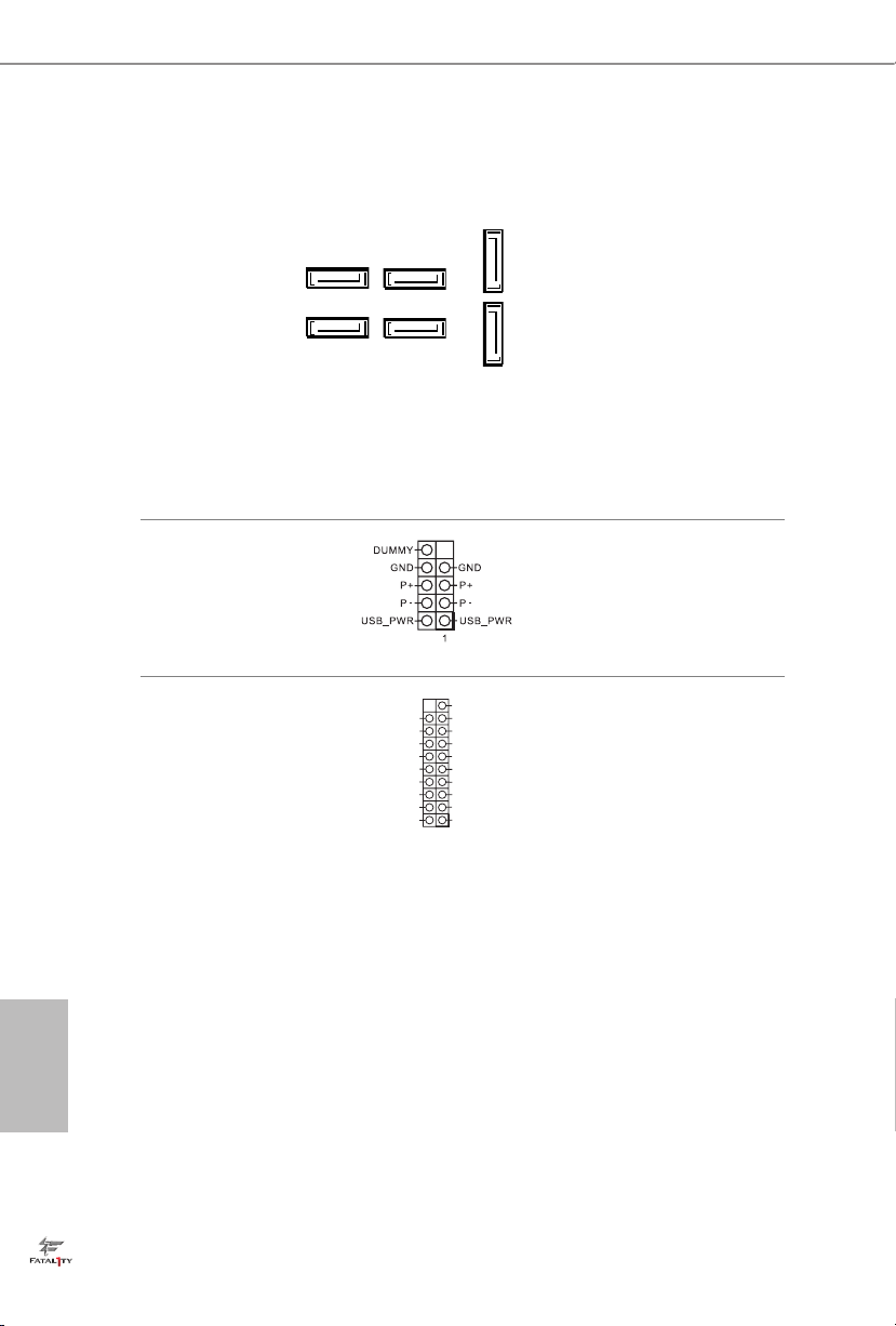
USB 2.0 Header
(9-pin USB1_2)
(see p.1, No. 13)
USB 3.1 Gen1 Header
(19-pin USB3_5_6)
(see p.1, No. 10)
IntA_PA_SSRX-
IntA_PA_SSRX+
IntA_PA_SSTX-
IntA_PA_SSTX+
IntA_PA_D-
IntA_PA_D+
Vbus
GND
GND
VbusVbus
IntA_PB_SSRX-
IntA_PB_SSRX+
GND
IntA_PB_SSTX-
IntA_PB_SSTX+
GND
IntA_PB_D-
IntA_PB_D+
Dummy
1
ere is one header on
this motherboard. Each
USB 2.0 header can
support two ports.
ere is one header on
this motherboard. Each
USB 3.1 Gen1 header can
support two ports.
22

Fatal1ty Z370 Gaming-ITX/ac Series
GND
FAN_VOLTAGE_CONTROL
FAN_SPEED
FAN_SPEED_CONTROL
GND
FAN_VOLTAGE_CONTROL
FAN_SPEED
FAN_SPEED_CONTROL
SPEAKER
Front Panel Audio Header
(9-pin HD_AUDIO1)
(see p.1, No. 19)
1. High Denition Audio supports Jack Sensing, but the panel wire on the chassis
must support HDA to function correctly. Plea se follow the instructions in our
manual and chassis manual to install your system.
2. If you use an AC’97 audio panel, please in stall it to the front panel audio header by
the steps below:
A. Connect Mic_ IN (MIC) to MIC2_L.
B. Conne ct Audio_R (RIN) to OUT2 _R and Audio_ L (LIN) to OUT2_ L.
C. Connect Ground (GND) to Ground (GND).
D. MIC_ RET and OUT_RET are for the HD audio panel only. You don’t need to
connect them for the AC’97 audio panel.
E. To activate the front mic, go to the “FrontMic” Tab in the Realtek Control panel
and adjust “Recording Volume”.
Chassis Speaker Header
(4-pin SPE AKER 1)
(see p.1, No. 14)
1
DUMMY
1
GND
PRESENCE#
MIC2_R
MIC2_L
+5V
MIC_RET
J_SENSE
OUT2_R
DUMMY
OUT_RET
OUT2_L
is header is for
connecting audio devices
to the front audio panel.
Please connect the chassis
speaker to this header.
Chassis Fan Connector
(4-pin CHA_FAN1)
(see p.1, No. 1)
CPU Fan Connector
(4-pin CPU_FAN1)
(see p.1, No. 3)
Please connect fan cables
to the fan connector and
match the black wire to
the ground pin.
is motherboard provides a 4-Pin CPU fan
(Quiet Fan) connector.
If you plan to connect a
3-Pin CPU fan, please
connect it to Pin 1-3.
English
23

CPU Optional/Water
1
GND
FAN_VOLTAGE_CONTROL
FAN_SPEED
FAN_SPEED_CONTROL
Pump Fan Connector
(4-pin CPU_OPT/W_
PUM P)
(see p.1, No. 4)
ATX Power Connector
(24-pin AT XPWR 1)
(see p.1, No. 7)
is motherboard
provides a 4-Pin water
cooling CPU fan
connector. If you plan
to connect a 3-Pin CPU
water cooler fan, please
connect it to Pin 1-3.
12
24
is motherboard provides a 24-pin ATX power
connector. To use a 20-pin
ATX power supply, please
plug it along Pin 1 and Pin
1
13
13.
English
ATX 12V Power
Connector
(8-pin ATX12V1)
(see p.1, No. 2)
Chassis Intrusion Header
(2-pin CI1)
(see p.1, No. 11)
8
GND
Signal
5
is motherboard provides a 8-pin ATX 12V
power connector. To use a
4-pin ATX power supply,
please plug it along Pin 1
and Pin 5.
is motherboard
supports CASE OPEN
1
detection feature that
detects if the chassis cove
has been removed. is
feature requires a chassis
with chassis intrusion
detection design.
24

Fatal1ty Z370 Gaming-ITX/ac Series
RGB LED Header
(4-pin RGB _LED1)
(see p.1, No. 6)
B
R
G
12V
1
RGB header is used to connect
RGB LED extension cable which
allows users to choose from
various LED lighting eects.
Caution: Never install the
RGB LED cable in the wrong
orientation; otherwise, the cable
may be damaged.
*Please refer to page 31 for
further instructions on this
header.
25
English

2.6 Smart Button
e motherboard has one smart buttone: Clear CMOS Button, allowing users to
clear the CMOS values.
Clear CMOS Button
(CLRCBTN)
(see p.4, No. 18)
is function is workable only when you power o your computer and unplug the
power supply.
Clear CMOS Button
allows users to quickly
clear the CMOS values.
English
26

Fatal1ty Z370 Gaming-ITX/ac Series
2.7 M.2_SSD (NGFF) Module Installation Guide
The M.2, also known as the Next Generation Form Factor (NGFF), is a small size and
versatile card edge connector that aims to replace mPCIe and mSATA. The Ultra M.2
Socket (M2_1) supports M.2 PCI Express module up to Gen3 x4 (32 Gb/s).
* Please be noted that if M2_1 is occupied by a SATA-type M.2 device, SATA3_0 will be
disabled.
Installing the M.2_SSD (NGFF) Module
Step 1
is motherboard supports M.2_SSD
(NGFF) module type 2260 and 2280
only. Prepare a proper PCB lenth of
module, the screw and the stando.
Step 2
Depending on the PCB type and
length of your M.2_SSD (NGFF)
module, nd the corresponding nut
2
1
location to be used.
A
B
No. 1 2
Nut Location A B
PCB Length 6cm 8cm
Module Type Type2 260 Type 2 280
English
27

Step 3
e stando is placed at the nut
location B by default. Skip Step 4 and
B
A
go straight to Step 5 if your M.2_SSD
(NGFF) module is type 2280. If your
M.2_SSD (NGFF) module is type
2260, go to Step 4.
Step 4
Peel o the yellow protective lm on
the nut location A. Hand tighten the
B
A
stando into the nut location A on
the motherboard.
Step 5
Align and gently insert the M.2
(NGFF) SSD module into the M.2
A
B
slot. Please be aware that the M.2
(NGFF) SSD module only ts in one
orientation.
English
28
AB
Step 6
Tighten the screw with a screwdriver
to secure the module into place.
Please do not overtighten the screw
AB
as this might damage the module.

M.2_SSD (NGFF) Module Support List
Vendor Interface P/N
ADATA SATA3 AXNS381E-128GM-B
ADATA SATA3 AX NS381E-256GM-B
ADATA SATA3 ASU800NS38-256GT-C
ADATA SATA3 ASU800NS38-512GT-C
ADATA PCIe3 x4 ASX7000NP-128GT-C
ADATA PCIe3 x4 ASX8000NP-256GM-C
ADATA PCIe3 x4 ASX7000NP-256GT-C
ADATA PCIe3 x4 ASX8000NP-512GM-C
ADATA PCIe3 x4 ASX7000NP-512GT-C
Apacer PCIe3 x4 AP240GZ280
Corsair PCIe3 x4 CSSD-F240GBMP500
Crucial SATA3 CT120M500SSD4
Crucial SATA3 CT240M500SSD4
Intel SATA3 Intel SSDSCKGW080A401/80G
Intel PCIe3 x4 SSDPEKKF256G7
Intel PCIe3 x4 SSDPEKK F512G7
Kingston SATA3 SM2280S3
Kingston PCIe3 x4 SKC1000/480G
Kingston PCIe2 x4 SH2280S3/480G
OCZ PCIe3 x4 RVD400 -M2280-512G (NVME)
PATRIOT PCIe3 x4 PH240GPM280SSDR NVME
Plextor PCIe3 x4 PX-128M8PeG
Plextor PCIe3 x4 PX-1TM8PeG
Plextor PCIe3 x4 PX-256M8PeG
Plextor PCIe3 x4 PX-512M8PeG
Plextor PCIe PX-G256M6e
Plextor PCIe PX-G512M6e
Samsung PCIe3 x4 SM961 MZVPW128HEGM (NVM)
Samsung PCIe3 x4 PM961 MZVLW128HEGR (NVME)
Samsung PCIe3 x4 960 EVO (MZ-V6E250) (NVME)
Samsung PCIe3 x4 960 EVO (MZ-V6E250BW) (NVME)
Samsung PCIe3 x4 SM951 (NVME)
Samsung PCIe3 x4 SM951 (MZHPV256HDGL)
Samsung PCIe3 x4 SM951 (MZHPV512HDGL)
Samsung PCIe3 x4 SM951 (NVME)
Samsung PCIe x4 XP941-512G (MZHPU512HCGL)
SanDisk PCIe SD6PP4M-128G
SanDisk PCIe SD6PP4M-256G
Team SATA3 TM8PS4128GMC105
Team SATA3 TM8PS4256GMC105
TEAM PCIe3 x4 TM8FP2240G0C101
TEAM PCIe3 x4 TM8FP2480GC110
Transcend SATA 3 TS512GMTS600
Fatal1ty Z370 Gaming-ITX/ac Series
English
29

Transcend SATA 3 TS512GMTS800
V-Co lor SATA3 VLM100-120G-2280B-RD
V-Co lor SATA3 VLM100 -240G-2280RGB
V-Co lor SATA3 VSM100-240G-2280
V-Co lor SATA3 VLM100 -240G-2280B-RD
WD SATA3 WDS100T1B0B-00AS40
WD SATA3 WDS240G1G0B-00RC30
WD PCIe3 x4 WDS256G1X0C-00ENX0 (NVME)
WD PCIe3 x4 WDS512G1X0C-0 0ENX0 (N VME)
For the latest updates of M.2_SSD (NFGG) module support list, please visit our website for
details: http://www.asrock.com
English
30

Fatal1ty Z370 Gaming-ITX/ac Series
2.8 ASRock RGB LED
ASRock RGB LED is a lighting control utility specically designed for unique individuals with
sophisticated tastes to build their own stylish colorful lighting system. Simply by connecting the
LED strip, you can customize various lighting schemes and patterns, including Static, Breathing,
Strobe, Cycling, Music, Wave and more.
Connecting the LED Strip
Connect your RGB LED strips to the
motherboard.
RGB LED Header (RGB_LED1)
RGB_LED1
B
R
x4
PCIe G en3
Ultr a M.2
Z37 0 G amin g-I TX/a c
G
12V
1
on the
1
1
B
1
R
G
V
2
1
1. Never install the RGB LED cable in the wrong orientation; otherwise, the cable
may be damaged.
2. Before installing or removing your RGB LED cable, please power o your system
and unplug the power cord from the power supply. Failure to do so may cause damages to motherboard components.
1. Plea se note that the RGB LED strips do not come with the package.
2. e RGB LED header support s standard 5050 RGB LED strip (12V/G/R/B), with a
maximum power rating of 3A (12V) and leng th within 2 meters.
English
31

ASRock RGB LED Utility
Now you can adjust the RGB LED color through the ASRock RGB LED utility. Download
this utility from the ASRock Live Update & APP Shop and start coloring your PC style
your way!
Drag the tab to customize your
preference.
Toggle on/o the
RGB LED switch
Sync RGB LED eects
for all LED regions of
the motherboard
Select a RGB LED light eect
from the drop-down menu.
English
32

Fatal1ty Z370 Gaming-ITX/ac Series
Kapitel 1 Einleitung
Vielen Dank, dass Sie sich für die ASRock Fatal1ty Z370 Gaming-ITX/ac-Series
entschieden haben – ein zuverlässiges Motherboard, das konsequent unter der
strengen Qualitätskontrolle von ASRock hergestellt wurde. Es liefert ausgezeichnete
Leistung mit robustem Design, das ASRock Streben nach Qualität und Beständigkeit
erfüllt.
Da die technischen Daten des Motherboards sowie die BIOS-Soware aktualisiert
werden können, kann der Inhalt dieser Dokumentation ohne Ankündigung geändert
werden. Falls diese Dokumentation irgendwelchen Änderungen unterliegt, wird die aktualisierte Version ohne weitere Hinweise auf der ASRock-Webseite zur Verfügung gestellt.
Sollten Sie technische Hilfe in Bezug auf dieses Motherboard benötigen, erhalten Sie auf
unserer Webseite spezischen Informationen über das von Ihnen verwendete Modell.
Auch nden Sie eine aktuelle Liste unterstützter VGA-Karten und Prozessoren auf der
ASRock-Webseite: ASRock-Website http://www.asrock.com.
1.1 Lieferumfang
Motherboard der ASRock Fatal1ty Z370 Gaming-ITX/ac-Series (Mini-ITX-Formfaktor)
•
Schnellanleitung zur ASRock Fatal1ty Z370 Gaming-ITX/ac Series
•
Support-CD zur ASRock Fatal1ty Z370 Gaming-ITX/ac-Series
•
2 x Serial-ATA- (SATA) Datenkabel (optional)
•
1 x ASRock-WiFi-2,4/5-GHz-Antenne (optional)
•
1 x Schraube für M.2-Sockel (optional)
•
1 x E/A-Blendenabschirmung
•
33
Deutsch

1.2 Technische Daten
Mini-ITX-Formfaktor
Plattform
•
8-Layer-PCB
•
4 x 2-oz-Kupfer
•
Prozessor
Chipsatz
Speicher
Unterstützt Intel® CoreTM-Prozessoren (Sockel 1151) der 8
•
Generation
Digi Power design
•
7-Leistungsphasendesign
•
Unterstützt Intel® Turbo Boost 2.0-Technologie
•
Unterstützt CPUs mit freiem Multiplikator der Intel® K-Serie
•
Unterstützt ASRock BCLK-Übertaktung (voller Bereich)
•
Intel® Z370
•
Dualkanal-DDR4-Speichertechnologie
•
2 x DDR4-DIMM-Steckplätze
•
Unterstützt DDR4 4333+(OC)*/4266(OC)/4133(OC)/4000(OC)/
•
3866(OC)/3800(OC)/3733(OC)/3600(OC)/3200(OC)/2933(OC)/
2800(OC)/2666/2400/2133 non-ECC, ungepuerter Speicher
* Weitere Informationen nden Sie in der Speicherkompatibilitätsliste
auf der ASRock-Webseite. (http://www.asrock.com/)
* Intel®-Prozessor der 8
Unterstützt ECC-UDIMM-Speichermodule (Betrieb im non-
•
ECC-Modus)
Systemspeicher, max. Kapazität: 32 GB
•
Unterstützt Intel® Extreme Memory Prole (XMP) 2.0
•
15-μ-Goldkontakt in DIMM-Steckplätze
•
ten
Generation unterstützt DDR4 bis 2666.
ten
Deutsch
34
Erweiterungssteckplatz
1 x PCI-Express 3.0-x16-Steckplatz (PCIE1:x16-Modus)
•
* Unterstützt PCIe-Riser-Karten zur Erweiterung eines x16Steckplatzes in zwei x8-Steckplätze
* Unterstützt NVMe-SSD als Bootplatte
1 x vertikaler M.2-Sockel (Key E) mit dem mitgelieferten
•
802.11ac-WLAN-Modul (an den rückseitigen E/A)
15-μ-Goldkontakt in VGA-PCIe-Steckplatz (PCIE1)
•

Fatal1ty Z370 Gaming-ITX/ac Series
Grakkarte
* Integrierte Intel® UHD Graphics-Visualisierung und VGAAusgänge können nur mit Prozessoren unterstützt werden, die GPUintegriert sind.
Unterstützt integrierte Intel® UHD Graphics-Visualisierung:
•
Intel® Quick Sync Video mit AVC, MVC (S3D) und MPEG2 Full HW Encode1, Intel® InTruTM 3D, Intel® Clear Video HD
Technology, Intel® InsiderTM, Intel® UHD Graphics
DirectX 12
•
HWA encodieren/decodieren: VP9 8 Bit, VP9 10 Bit (nur
•
Enkodierung), VP8, HEVC (MPEG-H Part 2, H.265), AVC
(MPEG4, H.264), MPEG2-Part2 (H.262), JPEG/MJPEG,VC-1
Max. geteilter Speicher 1024 MB
•
* Die Größe des maximalen Freigabespeichers kann je nach
Betriebssystem variieren.
Drei Grakkarten-Ausgangsoptionen: HDMI, DisplayPort 1.2
•
und Intel® underboltTM 3
Unterstützt drei Monitore
•
Unterstützt HDMI mit maximaler Auösung von 4K x 2K
•
(4096 x 2160) bei 60Hz
Unterstützt DisplayPort 1.2 mit maximaler Auösung von
•
4K x 2K (4096 x 2304) bei 60 Hz
Unterstützt Intel® underboltTM 3 mit maximaler Auösung von
•
4K x 2K (4096 x 2304) bei 60 Hz
Unterstützt Auto-Lippensynchronizität, hohe Farbtiefe
•
(12 bpc), xvYCC und HBR (Audio mit hoher Bitrate) mit HDMIPort(konformer HDMI-Monitor erforderlich)
Unterstützt HDCP mit HDMI, DisplayPort 1.2 und Intel®
•
underboltTM 3
Unterstützt 4K-Ultra-HD- (UHD) Wiedergabe mit HDMI,
•
DisplayPort 1.2 und Intel® underboltTM 3
Audio
7.1-Kanal-HD-Audio mit Inhaltsschutz (Realtek ALC1220-
•
Audiocodec)
Erstklassige Blu-ray-Audiounterstützung
•
Unterstützt Überspannungsschutz
•
Nichicon-Audiokappen der Fine Gold-Serie
•
120-dB-SRV-DAC mit Dierentialverstärker
•
NE5532 – erstklassiger Headset-Verstärker für Audioanschluss
•
an der Frontblende (unterstützt Headsets mit bis zu 600 Ohm)
Reiner Stromeingang
•
Deutsch
35

Deutsch
LAN
Wireless LAN
Rückblende, E/A
Direct Drive Technology
•
PCB-isolierte Abschirmung
•
Impedanzerkennung am vorderen Ausgang
•
Individuelle PCB-Layer für rechten/linken Audiokanal
•
15-μ-Gold-Audioanschluss
•
Unterstützt Creative SoundBlaster Cinema3
•
Gigabit LAN 10/100/1000 Mb/s
•
Giga PHY Intel® I219V
•
Unterstützt Wake-On-LAN
•
Unterstützt Schutz gegen Blitzschlag/elektrostatische Entladung
•
Unterstützt energieezientes Ethernet 802.3az
•
Unterstützt PXE
•
Intel®-802.11ac-WLAN-Modul 8265
•
Unterstützt IEEE 802.11a/b/g/n/ac
•
Unterstützt Dualband (2,4/5 GHz mit 80-MHz-Bandbreite und
•
MU-MIMO)
Unterstützt High-Speed-Drahtlosverbindung bis 867 Mb/s
•
2 Antennen zur Unterstützung von Diversitätstechnologie 2
•
(senden) x 2 (empfangen)
Unterstützt Bluetooth 4.2 / 3.0 + High-Speed, Klasse II
•
2 x Antennenanschluss
•
1 x PS/2-Maus-/Tastaturanschluss
•
1 x HDMI-Port
•
1 x DisplayPort 1.2
•
1 x Intel® underboltTM 3 (kompatibel mit USB 3.1 Gen2 und
•
USB-C-Anzeige)*
* Unterstützt Auadung per USB PD 2.0 bis 12 V bei 3 A (36 W)
1 x Optischer SPDIF-Ausgang
•
6 x USB-3.1-Gen1-Ports (unterstützt Schutz gegen
•
elektrostatische Entladung)
* 1 x Fatal1ty-Mausanschluss (USB 3.1 Gen1) ist inklusive
1 x RJ-45-LAN-Port mit LED (Aktivität/Verbindung-LED und
•
Geschwindigkeit-LED)
1 x CMOS-löschen-Taste
•
HD-Audioanschlüsse: Seitlicher Lautsprecher / Hinterer
•
Lautsprecher / Zentral / Bass / Line-in / Vorderer Lautsprecher /
Mikrofon
36

Speicher
Anschluss
Fatal1ty Z370 Gaming-ITX/ac Series
6 x SATA-III-6,0-Gb/s-Abschluss, unterstützt RAID (RAID 0,
•
RAID 1, RAID 5, RAID 10, Intel Rapid Storage Technology 15),
NCQ, AHCI und Hot-Plugging*
* Wenn M2_1 durch ein SATA-Typ-M.2-Gerät belegt ist, wird
SATA3_0 deaktiviert.
1 x Ultra-M.2-Sockel, unterstützt M-Key-Typ-2260/2280-M.2-
•
SATA-III-6,0-Gb/s-Modul und M.2-PCI-Express-Modul bis
Gen3 x 4 (32 Gb/s)**
** Unterstützt Intel® OptaneTM-Technologie
** Unterstützt NVMe-SSD als Bootplatte
1 x Gehäuseeingri-Stileiste
•
1 x RGB-LED-Stileiste
•
* Unterstützt insgesamt bis zu 12 V/3 A, 36-W-LED-Streifen
1 x CPU-Lüeranschluss (4-polig)
•
* Der CPU-Lüeranschluss unterstützt einen CPU-Lüer mit einer
maximalen Lüerleistung von 1 A (12 W).
1 x Anschluss für Optionale-CPU-/Wasserpumpenlüer
•
(4-polig) (intelligente Lüergeschwindigkeitssteuerung)
* Der Optionale-CPU-/Wasserpumpenlüer unterstützt einen Wasserkühlerlüer mit einer maximalen Lüerleistung von 1,5 A (18 W).
* CPU_OPT/W_PUMP können automatisch erkennen, ob ein 3oder 4-poliger Lüer verwendet wird.
1 x Gehäuselüeranschluss (4-polig)
•
1 x 24-poliger ATX-Netzanschluss
•
1 x 8-poliger 12-V-Netzanschluss (hochdichter Netzanschluss)
•
1 x Audioanschluss an der Frontblende (15μ goldene
•
Audioanschluss)
1 x USB 2.0-Stileiste (unterstützt zwei USB 2.0-Ports)
•
(unterstützt Schutz gegen elektrostatische Entladung)
1 x USB 3.1 Gen1-Stileiste (unterstützt zwei USB 3.1 Gen1-
•
Ports) (unterstützt Schutz gegen elektrostatische Entladung)
BIOS-Funktion
AMI-UEFI-Legal-BIOS mit Unterstützung mehrsprachiger
•
grascher Benutzerschnittstellen
ACPI 6.0-konforme Aufweckereignisse
•
SMBIOS 2.7-Unterstützung
•
CPU, DRAM, PCH 1,0V, VCCIO, VCCST, VCCSA, VCCPLL
•
Mehrfachspannungsanpassung
Deutsch
37

Temperaturerkennung: CPU, optionale CPU/Wasserpumpe,
Hardwareüberwachung
•
Gehäuselüer
Lüertachometer: CPU, optionale CPU/Wasserpumpe, Gehäu-
•
selüer
Lautloser Lüer (automatische Anpassung der Gehäuselüerge-
•
schwindigkeit durch CPU-Temperatur): CPU, optionale CPU/
Wasserpumpe, Gehäuselüer
Mehrfachgeschwindigkeitssteuerung: CPU, optionale CPU/Was-
•
serpumpe, Gehäuselüer
Gehäuse-oen-Erkennung
•
Spannungsüberwachung: +12 V, +5 V, +3,3 V, CPU Vcore,
•
DRAM, PCH 1,0V, VCCIO, VCCSA, VCCST
Microso® Windows® 10, 64 Bit
Betriebssystem
Zertizierungen
* Detaillierte Produktinformationen nden Sie auf unserer Webseite: http://www.asrock.com
Bitte beachten Sie, dass mit einer Übertaktung, zu der die Anpassung von BIOSEinstellungen, die Anwendung der Untied Overclocking Technology oder die Nutzung
von Übertaktungswerkzeugen von Drittanbietern zählen, bestimmte Risiken verbunden
sind. Eine Übertaktung kann sich auf die Stabilität Ihres Systems auswirken und sogar
Komponenten und Geräte Ihres Systems beschädigen. Sie sollte auf eigene Gefahr und
eigene Kosten durchgeführt werden. Wir übernehmen keine Verantwortung für mögliche
Schäden, die durch eine Übertaktung verursacht wurden.
•
FCC, CE
•
ErP/EuP ready (ErP/EuP ready-Netzteil erforderlich)
•
Deutsch
38

Fatal1ty Z370 Gaming-ITX/ac Series
1.3 Integrierte Stiftleisten und Anschlüsse
Integrierte Stileisten und Anschlüsse sind KEINE Jumper. Bringen Sie KEINE JumperKappen an diesen Stileisten und Anschlüssen an. Durch Anbringen von Jumper-Kappen
an diesen Stileisten und Anschlüssen können Sie das Motherboard dauerha beschädigen.
Systemblende-Stileiste
(9-polig, PANEL1)
(siehe S. 1, Nr. 12)
PWRBTN (Ein-/Austaste):
Mit der Ein-/Austaste an der Frontblende des Gehäuses verbinden. Sie können die
Abschaltung Ihres Systems über die Ein-/Austaste kongurieren.
RESET (Reset-Taste):
Mit der Reset-Taste an der Frontblende des Gehäuses verbinden. Starten Sie den Computer über die Reset-Taste neu, wenn er abstürzt oder sich nicht normal neu starten lässt.
PLED (Systembetriebs-LED):
Mit der Betriebsstatusanzeige an der Frontblende des Gehäuses verbinden. Die LED
leuchtet, wenn das System läu. Die LED blinkt, wenn sich das System im S1/S3-Ruhezustand bendet. Die LED ist aus, wenn sich das System im S4-Ruhezustand bendet
oder ausgeschaltet ist (S5).
HDLED (Festplattenaktivitäts-LED):
Mit der Festplattenaktivitäts-LED an der Frontblende des Gehäuses verbinden. Die LED
leuchtet, wenn die Festplatte Daten liest oder schreibt.
Das Design der Frontblende kann je nach Gehäuse variieren. Ein Frontblendenmodul
besteht hauptsächlich aus Ein-/Austaste, Reset-Taste, Betrieb-LED, FestplattenaktivitätLED, Lautsprecher etc. Stellen Sie beim Anschließen Ihres Frontblendenmoduls an diese
Stileiste sicher, dass Kabel- und Pinbelegung richtig abgestimmt sind.
GND RESET#
PWRBTN#
PLED-
PLED+
GND
GND
HDLED-
HDLED+
1
Verbinden Sie Ein-/
Austaste, Reset-Taste und
Systemstatusanzeige am
Gehäuse entsprechend
der nachstehenden
Pinbelegung mit dieser
Stileiste. Beachten Sie vor
Anschließen der Kabel die
positiven und negativen
Kontakte.
39
Deutsch
Serial-ATA-III-Anschlüsse
(SATA3_0:
siehe S. 1, Nr. 17)
(SATA3_1:
SATA3_3
siehe S. 1, Nr. 16)
(SATA3_2:
SATA3_0
siehe S. 1, Nr. 15)
(SATA3_3:
siehe S. 1, Nr. 18)
(SATA3_4:
siehe S. 1, Nr. 9)
(SATA3_5:
siehe S. 1, Nr. 8)
SATA3_2
SATA3_1
Diese sechs SATA-IIIAnschlüsse unterstützen
SATA-Datenkabel für interne
Speichergeräte mit einer Da
tenübertragungsgeschwin
SATA3_5
digkeit bis 6,0 Gb/s. Wenn
M2_1 durch ein SATA-TypM.2-Gerät belegt ist, wird
SATA3_4
SATA3_0 deaktiviert.
Deutsch
USB 2.0-Stileiste
(9-polig, USB1_2)
(siehe S. 1, Nr. 13)
USB 3.1 Gen1-Stileiste
(19-polig, USB3_5_6)
(siehe S. 1, Nr. 10)
IntA_PA_SSRX-
IntA_PA_SSRX+
IntA_PA_SSTX-
IntA_PA_SSTX+
IntA_PA_D-
IntA_PA_D+
Vbus
GND
GND
VbusVbus
IntA_PB_SSRX-
IntA_PB_SSRX+
GND
IntA_PB_SSTX-
IntA_PB_SSTX+
GND
IntA_PB_D-
IntA_PB_D+
Dummy
1
Es gibt eine Stileiste an
diesem Motherboard. Jede
USB 2.0-Stileiste kann
zwei Ports unterstützen.
Es gibt eine Stileiste an
diesem Motherboard.
Jede USB 3.1 Gen1Stileiste kann zwei Ports
unterstützen.
40

Fatal1ty Z370 Gaming-ITX/ac Series
GND
FAN_VOLTAGE_CONTROL
FAN_SPEED
FAN_SPEED_CONTROL
GND
FAN_VOLTAGE_CONTROL
FAN_SPEED
FAN_SPEED_CONTROL
SPEAKER
Audiostileiste
(Frontblende)
(9-polig, HD_AUDIO1)
(siehe S. 1, Nr. 19)
1. High Denition Audio unterstützt Anschlusserkennung, der Draht am Gehäuse muss
dazu jedoch HDA unterstützt. Bitte befolgen Sie zum Installieren Ihres Systems die
Anweisungen in unserer Anleitung und der Anleitung zum Gehäuse.
2. Bei Nutzung eines AC’97-Audiopanels dieses bitte anhand folgender Schritte an der
Audiostileiste der Frontblende installieren:
A. Mic_IN (Mikrofon) mit MIC2_L verbinden.
B. Audio_R (RIN) mit OUT2_R und Audio_L (LIN) mit OUT2_L verbinden.
C. Erde (GND) mit Erde (GND) verbinden.
D. MIC_RET und OUT_RET sind nur für das HD-Audiopanel vorgesehen. Sie müssen
sie nicht für das AC’97-Audiopanel verbinden.
E. Rufen Sie zum Aktivieren des vorderen Mikrofons das „FrontMic (Vorderes
Mikrofon)“-Register in der Realtek-Systemsteuerung auf und passen „Recording
Volume (Aufnahmelautstärke)“ an.
Gehäuselautsprecherstileiste
(4-polig, SPEAKER1)
(siehe S. 1, Nr. 14)
1
DUMMY
1
GND
PRESENCE#
MIC2_R
MIC2_L
+5V
MIC_RET
J_SENSE
OUT2_R
DUMMY
OUT_RET
OUT2_L
Diese Stileiste dient
dem Anschließen von
Audiogeräten an der
Frontblende.
Bitte verbinden Sie den
Gehäuselautsprecher mit
dieser Stileiste.
Gehäuselüeranschluss
(4-polig, CHA_FAN1)
(siehe S. 1, Nr. 1)
CPU-Lüeranschluss
(4-polig, CPU_FAN1)
(siehe S. 1, Nr. 3)
Bitte verbinden Sie das
Lüerkabel mit dem
Lüeranschluss; der
schwarze Draht gehört
zum Erdungskontakt.
Dieses Motherboard bietet
einen 4-poligen CPULüeranschluss (lautloser
Lüer). Falls Sie einen
3-poligen CPU-Lüer
anschließen möchten,
verbinden Sie ihn bitte mit
Kontakt 1 bis 3.
Deutsch
41

Optionale-CPU-/
5
1
8
GND
FAN_VOLTAGE_CONTROL
FAN_SPEED
FAN_SPEED_CONTROL
WasserpumpenLüeranschluss
(4-polig, CPU_OPT/W_
PUMP)
(siehe S. 1, Nr. 4)
ATX-Netzanschluss
(24-polig, ATXPWR1)
(siehe S. 1, Nr. 7)
Dieses Motherboard bietet einen 4-poligen WasserkühlungCPU-Lüeranschluss. Falls Sie
einen 3-poligen CPU-Wasserkühlerlüer anschließen
möchten, verbinden Sie ihn
bitte mit Kontakt 1 bis 3.
12
24
Dieses Motherboard bietet
einen 24-poligen ATX-Netzanschluss. Bitte schließen
Sie es zur Nutzung eines
20-poligen ATX-Netzteils
1
13
entlang Kontakt 1 und Kontakt 13 an.
Deutsch
ATX-12-V-Netzanschluss
(8-polig, ATX12V1)
(siehe S. 1, Nr. 2)
Gehäuseeingri-Stileiste
(2-polig, CI1)
(siehe S. 1, Nr. 11)
GND
Signal
Dieses Motherboard bietet
einen 8-poligen ATX12-V-Netzanschluss. Bitte
schließen Sie es zur Nutzung eines 4-poligen ATXNetzteils entlang Kontakt 1
und Kontakt 5 an.
Dieses Motherboard
unterstützt die Gehäuse-
1
oen-Erkennung, die erkennt,
wenn die Gehäuseabdeckung
entfernt wurde. Diese
Funktion setzt ein Gehäuse mit
Gehäuseeingrierkennungsdesign voraus.
42

Fatal1ty Z370 Gaming-ITX/ac Series
RGB-LED-Stileiste
(4-polig, RGB_LED1)
(siehe S. 1, Nr. 6)
B
R
G
12V
1
RGB-Stileiste dient dem
Anschließen eines RGB-LEDErweiterungskabels, das dem
Nutzer die Auswahl zwischen
verschiedenen LED-Lichteekten
ermöglicht.
Achtung: Installieren Sie das
RGB-LED-Kabel niemals falsch
herum; andernfalls könnte das
Kabel beschädigt werden.
*Weitere Anweisungen zu dieser
Stileiste nden Sie auf Seite 31.
43
Deutsch

1.4 Intelligente Taste
Das Motherboard hat eine intelligente Taste: CMOS-leeren-Taste, mit der Nutzer die
CMOS-Werte löschen können.
CMOS-löschen-Taste
(CLRCBTN)
(siehe S. 4, Nr. 18)
Diese Funktion ist nur verfügbar, wenn Sie Ihren Computer abschalten und die Stromversorgung unterbrechen.
Mit der CMOS-löschenTaste können Benutzer
die CMOS-Werte schnell
löschen.
Deutsch
44

Fatal1ty Z370 Gaming-ITX/ac Series
Chapitre 1 Introduction
Nous vous remercions d’avoir acheté cette carte mère ASRock de la série ASRock
Fatal1ty Z370 Gaming-ITX/ac, une carte mère able fabriquée conformément
au contrôle de qualité rigoureux et constant appliqué par ASRock. Fidèle à son
engagement de qualité et de durabilité, ASRock vous garantit une carte mère de
conception robuste aux performances élevées.
Les spécications de la carte mère et du logiciel BIOS pouvant être mises à jour, le contenu
de ce document est soumis à modication sans préavis. En cas de modications du présent
document, la version mise à jour sera disponible sur le site Internet ASRock sans notication préalable. Si vous avez besoin d’une assistance technique pour votre carte mère,
veuillez visiter notre site Internet pour plus de détails sur le modèle que vous utilisez. La
liste la plus récente des cartes VGA et des processeurs pris en charge est également disponible sur le site Internet de ASRock. Site Internet ASRock http://www.asrock.com.
1.1 Contenu de l’emballage
Carte mère ASRock Fatal1ty Z370 Gaming-ITX/ac Series (facteur de forme Mini-ITX)
•
Guide d'installation rapide pour la ASRock Fatal1ty Z370 Gaming-ITX/ac Series
•
CD de support pour la ASRock Fatal1ty Z370 Gaming-ITX/ac Series
•
2 x câbles de données Serial ATA (SATA) (Optionnel)
•
1 x antenne Wi-Fi 2,4/5 GHz ASRock (Optionnel)
•
1 x vis pour socket M.2 (Optionnel)
•
1 x panneau de protection E/S
•
45
Français

1.2 Spécications
Plateforme
•
•
•
Facteur de forme Mini-ITX
PCB 8 couches
4 x cuivre 2 onces
Français
Processeur
Chipset
Mémoire
Prend en charge les processeurs 8
•
(socket 1151)
Digi Power design
•
Alimentation à 7 phases
•
Prend en charge la technologie Intel® Turbo Boost 2.0
•
Prend en charge les processeurs débloqués de la série K Intel®
•
Prend en charge l’overclocking ASRock BCLK Full-range
•
Intel® Z370
•
Technologie mémoire double canal DDR4
•
2 x fentes DIMM DDR4
•
Prend en charge les mémoires sans tampon non ECC DDR4
•
4333+(OC)*/4266(OC)/4133(OC)/4000(OC)/3866(OC)/
3800(OC)/3733(OC)/3600(OC)/3200(OC)/2933(OC)/
2800(OC)/2666/2400/2133
* Veuillez consulter la liste de prise en charge des mémoires sur le
site Web d'ASRock pour de plus amples informations. (http://www.
asrock.com/)
ème
* 8
génération de CPU Intel® prend en charge DDR4 jusqu'à 2666.
Prend en charge les modules mémoire UDIMM ECC (fonctionne
•
en mode non-ECC)
Capacité max. de la mémoire système : 32Go
•
Prend en charge Intel® Extreme Memory Prole (XMP) 2.0
•
Contacts dorés 15μ sur fentes DIMM
•
ème
génération Intel® CoreTM
46
Fente
d’expansion
1 x fente PCI Express 3.0 x 16 (PCIE1:mode x16)
•
* Prend en charge les cartes adaptatrices PCIe pour étendre un
emplacement x16 à deux emplacements x8
* Prend en charge les SSD NVMe comme disques de démarrage
1 x socket M.2 vertical (touche E) avec le module Wi-Fi 802.11ac
•
fourni (sur l'E/S arrière)
Contact doré 15μ dans fente VGA PCIe (PCIE1)
•

Fatal1ty Z370 Gaming-ITX/ac Series
Graphiques
* La technologie Intel® UHD Graphics Built-in Visuals et les sorties
VGA sont uniquement prises en charge par les processeurs intégrant
un contrôleur graphique.
Prend en charge la technologie Intel® UHD Graphics Built-
•
in Visuals : Intel® Quick Sync Video avec AVC, MVC (S3D) et
MPEG-2 Full HW Encode1, Intel® InTruTM 3D, Intel® Clear Video
HD Technology, Intel® InsiderTM, Intel® UHD Graphics
DirectX 12
•
Codage/Décodage HWA : VP9 8bits, VP9 10bits (Encodage
•
uniquement), VP8, HEVC (MPEG-H Part2, h.265), AVC
(MPEG4, h.264), MPEG2-Part2 (h.262), JPEG/MJPEG,VC-1
Mémoire partagée max. 1024 Mo
•
* La taille de la mémoire partagée maximale peut varier selon les
diérents systèmes d'exploitation.
Trois options de sortie graphique : HDMI, DisplayPort 1.2 et
•
Intel® underboltTM 3
Prend en charge la conguration à triple moniteurs
•
Prend en charge la technologie HDMI avec résolution maximale
•
de 4K × 2K (4096x2160) @ 60Hz
Prend en charge la technologie DisplayPort 1.2 avec résolution
•
maximale de 4K × 2K (4096x2304) @ 60Hz
Prend en charge Intel® underboltTM 3 avec résolution maximale
•
de 4K × 2K (4096x2304) @ 60Hz
Prend en charge les technologies Auto Lip Sync, Deep Color
•
(12bpc), xvYCC et HBR (High Bit Rate Audio) avec port
HDMI(un moniteur compatible HDMI est requis)
Prend en charge HDCP avec HDMI, DisplayPort 1.2 et Intel®
•
underboltTM 3
Prend en charge la lecture 4K Ultra HD (UHD) avec HDMI,
•
DisplayPort 1.2 et Intel® underboltTM 3
Audio
Audio 7.1 CH HD avec protection du contenu (codec audio
•
Realtek ALC1220)
Compatible audio Blu-ray Premium
•
Prend en charge la protection contre les surtensions
•
Couvercles audio série en or n Nichicon
•
120dB SNR DAC avec amplicateur diérentiel
•
Amplicateur de casque NE5532 Premium pour connecteur
•
audio sur panneau avant (prend en charge les casques jusqu’à 600
Ohms)
Entrée d’alimentation Pure Power
•
Français
47

Réseau
Réseau sans-l
Technologie Direct Drive
•
Blindage isolant PCB
•
Détection d'impédance sur le port de sortie avant
•
Couches de PCB individuelles pour canal audio D/G
•
Connecteur audio or 15μ
•
Prend en charge Creative SoundBlaster Cinema3
•
Gigabit LAN 10/100/1000 Mo/s
•
Giga PHY Intel® I219V
•
Prend en charge la fonction Wake-On-LAN
•
Prend en charge la protection contre la foudre/les décharges
•
électrostatiques
Prend en charge la fonction d’économie d’énergie Ethernet
•
802.3az
Prend en charge PXE
•
Module Wi-Fi 802.11ac Intel® 8265
•
Prend en charge IEEE 802.11a/b/g/n/ac
•
Prend en charge le mode Dual-Band (2,4/5 GHz avec bande pas-
•
sante 80 Mhz et MU-MIMO)
Prend en charge la connexion sans-l à haute vitesse jusqu’à
•
867 Mbps
2 antennes pour prendre en charge la technologie diversiée 2
•
(émission) x 2 (réception)
Prend en charge Bluetooth 4.2 / 3.0 + haute vitesse classe II
•
Français
48
Connectique
du panneau
arrière
2 x ports antenne
•
1 x port souris/clavier PS/2
•
1 x port HDMI
•
1 x DisplayPort 1.2
•
1 x Intel® underboltTM 3 (Compatible avec achage USB 3.1
•
Gen2 et USB-C)*
* Gère le chargement USB PD 2.0 jusqu'à 12 V @ 3 A (36 W)
1 x port sortie optique SPDIF
•
6 x ports USB 3.1 Gen1 (Protection contre les décharges
•
électrostatiques)
* 1 x port souris Fatal1ty (USB 3.1 Gen1) est inclus
1 x port RJ-45 LAN avec LED (LED ACT/LIEN et LED
•
VITESSE)
1 x bouton Clear CMOS
•
Connecteurs jack audio HD : Haut-parleur latéral / haut-parleur
•
arrière / central / basses / entrée ligne / haut-parleur avant /
microphone

Stockage
Connecteur
Caractéristiques du BIOS
Fatal1ty Z370 Gaming-ITX/ac Series
6 x connecteurs SATA3 6,0 Go/s, compatibles RAID (RAID 0,
•
RAID 1, RAID 5, RAID 10, technologies Intel Rapid Storage 15),
NCQ, AHCI etHot Plug*
* Si M2_1 est occupé par un périphérique M.2 type SATA, SATA3_0
est désactivé.
1 x socket Ultra M.2, prend en charge les modules M.2 SATA3
•
6,0 Go/s type 2260/2280 touche M et M.2 PCI Express jusqu'à
Gen3 x4 (32 Go/s)*
** Prend en charge Intel® OptaneTM Technology
** Prend en charge les SSD NVMe comme disques de démarrage
1 x embase d’intrusion châssis
•
1 x embase LED RVB
•
* Prend en charge les rubans LED jusqu'à 12 V/3 A, 36 W au total
1 x connecteur pour ventilateur de CPU (4 broches)
•
* Le connecteur pour ventilateur de CPU prend en charge un ventilateur de CPU d'une puissance maximale de 1 A (12 W).
1 x connecteur pour ventilateur de processeur optionnel/pompe
•
à eau (4 broches) (contrôle de vitesse de ventilateur intelligent)
* Le ventilateur de processeur optionnel/pompe à eau prend en
charge un ventilateur de refroidisseur d'eau d'une puissance maximale de 1,5 A (18 W).
* CPU_OPT/W_PUMP peuvent détecter automatiquement si un
ventilateur 3 broches ou 4 broches est utilisé.
1 x connecteur pour ventilateur de châssis (4 broches)
•
1 x connecteur d’alimentation ATX 24 broches
•
1 x connecteur d’alimentation 12V 8 broches (connecteur
•
d’alimentation haute densité)
1 x Connecteur audio panneau avant (15μ Connecteur audio or)
•
1 x embase USB 2.0 (2 ports USB 2.0 pris en charge) (Protection
•
contre les décharges électrostatiques)
1 x embase USB 3.1 Gen1 (2 ports USB 3.1 Gen1 pris en charge)
•
(Protection contre les décharges électrostatiques)
BIOS UEFI AMI avec prise en charge d’interface graphique
•
multilingue
Compatible ACPI 6.0 Wake Up Events
•
Compatible SMBIOS 2.7
•
Réglage de la tension CPU, DRAM, PCH 1,0 V, VCCIO, VCCST,
•
VCCSA, VCCPLL
Français
49

Détection de température : Ventilateurs de CPU, CPU optionnel/
Surveillance
du matériel
•
pompe à eau, châssis
Tachymètre de ventilateur : Ventilateurs de CPU, CPU optionnel/
•
pompe à eau, châssis
Ventilateur silencieux (réglage automatique de la vitesse du ven-
•
tilateur du châssis d’après la température du CPU) : Ventilateurs
de CPU, CPU optionnel/pompe à eau, châssis
Contrôle simultané des vitesses du ventilateur : Ventilateurs de
•
CPU, CPU optionnel/pompe à eau, châssis
Détection CHÂSSIS OUVERT
•
Surveillance de la tension d’alimentation : +12V, +5V, +3,3V,
•
CPU Vcore, DRAM, PCH 1,0V, VCCIO, VCCSA, VCCST
Microso® Windows® 10 64 bits
Système
•
d’exploitation
FCC, CE
Certications
* pour des informations détaillées de nos produits, veuillez visiter notre site: http://www.asrock.com
Il est important de signaler que l’overclocking présente certains risques, incluant des
modications du BIOS, l’application d’une technologie d’overclocking déliée et l’utilisation
d’outils d’overclocking développés par des tiers. La stabilité de votre système peut être affectée par ces pratiques, voire provoquer des dommages aux composants et aux périphériques du système. L’overclocking se fait à vos risques et périls. Nous ne pourrons en aucun
cas être tenus pour responsables des dommages éventuels provoqués par l’overclocking.
•
ErP/EuP Ready (alimentation ErP/EuP ready requise)
•
Français
50

Fatal1ty Z370 Gaming-ITX/ac Series
1.3 Embases et connecteurs de la carte mère
Les embases et connecteurs situés sur la carte NE SONT PAS des cavaliers. Ne placez
JAMAIS de capuchons de cavaliers sur ces embases ou connecteurs. Placer un capuchon de
cavalier sur ces embases ou connecteurs endommagera irrémédiablement votre carte mère.
Embase du panneau
système
(PANNEAU1 à 9 broches)
(voir p.1, No. 12)
PWRBTN (bouton d’alimentation):
pour brancher le bouton d’alimentation du panneau frontal du châssis. Vous pouvez
congurer la façon dont votre système doit s’arrêter à l’aide du bouton d'alimentation.
RESET (bouton de réinitialisation):
pour brancher le bouton de réinitialisation du panneau frontal du châssis. Appuyez sur le
bouton de réinitialisation pour redémarrer l’ordinateur en cas de plantage ou de dysfonctionnement au démarrage.
PLED (LED d’alimentation du système) :
pour brancher le témoin d’état de l’alimentation du panneau frontal du châssis. Le LED
est allumé lorsque le système fonctionne. Le LED clignote lorsque le système se trouve en
mode veille S1/S3. Le LED est éteint lorsque le système se trouve en mode veille S4 ou
hors tension (S5).
HDLED (LED d’activité du disque dur) :
pour brancher le témoin LED d’activité du disque dur du panneau frontal du châssis. Le
LED est allumé lorsque le disque dur lit ou écrit des données.
La conception du panneau frontal peut varier en fonction du châssis. Un module de
panneau frontal est principalement composé d’un bouton d'alimentation, d'un bouton de
réinitialisation, d'un témoin LED d’alimentation, d'un témoin LED d’activité du disque
dur, d'un haut-parleur etc. Lorsque vous reliez le module du panneau frontal de votre
châssis sur cette embase, veillez à parfaitement faire correspondre les ls et les broches.
GND RESET#
PWRBTN#
PLED-
PLED+
GND
GND
HDLED-
HDLED+
1
Branchez le bouton de
mise en marche, le bouton
de réinitialisation et le
témoin d’état du système
présents sur le châssis
sur cette embase en
respectant la conguration
des broches illustrée
ci-dessous. Repérez
les broches positive et
négative avant de brancher
les câbles.
Français
51

Connecteurs Serial ATA3
(SATA3_0:
voir p.1, No. 17)
(SATA3_1:
voir p.1, No. 16)
(SATA3_2:
voir p.1, No. 15)
(SATA3_3:
voir p.1, No. 18)
(SATA3_4:
voir p.1, No. 9)
(SATA3_5:
voir p.1, No. 8)
SATA3_3
SATA3_0
SATA3_2
SATA3_1
Ces six connecteurs
SATA3 sont compatibles
avec les câbles de données
SATA pour les appareils
de stockage internes
SATA3_5
avec un taux de transfert
maximal de 6,0 Go/s.
Si M2_1 est occupé par
SATA3_4
un périphérique M.2
type SATA, SATA3_0 est
désactivé.
Français
Embase USB 2.0
(USB1_2 9broches)
(voir p.1, No. 13)
Embase USB 3.1 Gen1
(USB3_5_6 à 19 broches)
(voir p.1, No. 10)
IntA_PA_SSRX-
IntA_PA_SSRX+
IntA_PA_SSTX-
IntA_PA_SSTX+
IntA_PA_D-
IntA_PA_D+
Vbus
GND
GND
VbusVbus
IntA_PB_SSRX-
IntA_PB_SSRX+
GND
IntA_PB_SSTX-
IntA_PB_SSTX+
GND
IntA_PB_D-
IntA_PB_D+
Dummy
1
Cette carte mère comprend
un connecteur. Chaque
embase USB 2.0 peut
prendre en charge deux
ports.
Cette carte mère comprend
un connecteur. Chaque
embase USB 3.1 Gen1 peut
prendre en charge deux
ports.
52

Fatal1ty Z370 Gaming-ITX/ac Series
GND
FAN_VOLTAGE_CONTROL
FAN_SPEED
FAN_SPEED_CONTROL
GND
FAN_VOLTAGE_CONTROL
FAN_SPEED
FAN_SPEED_CONTROL
SPEAKER
Embase audio du panneau
frontal
(HD_AUDIO1 à 9
broches)
(voir p.1, No. 19)
1. L’audio haute dénition prend en charge la technologie Jack Sensing (détection de la
che), mais le panneau grillagé du châssis doit être compatible avec la HDA pour
fonctionner correctement. Veuillez suivre les instructions gurant dans notre manuel et
dans le manuel du châssis pour installer votre système.
2. Si vous utilisez un panneau audio AC’97, veuillez le brancher sur l’embase audio du
panneau frontal en procédant comme suit :
A. branchez Mic_IN (MIC) sur MIC2_L.
B. branchez Audio_R (RIN) sur OUT2_R et Audio_L (LIN) sur OUT2_L.
C. branchez la mise à terre (GND) sur mise à terre (GND).
D. MIC_RET et OUT_RET sont exclusivement réservés au panneau audio HD. Il est
inutile de les brancher avec le panneau audio AC’97.
E. Pour activer le micro frontal, sélectionnez l’onglet «FrontMic» du panneau de
contrôle Realtek et réglez le paramètre «Volume d’enregistrement».
Embase du haut-parleur
du châssis
(SPEAKER1 à 4 broches)
(voir p.1, No. 14)
1
DUMMY
1
GND
PRESENCE#
MIC2_R
MIC2_L
+5V
MIC_RET
J_SENSE
OUT2_R
DUMMY
OUT_RET
OUT2_L
Cette embase sert au
branchement des appareils
audio au panneau audio
frontal.
Veuillez brancher le hautparleur du châssis sur cette
embase.
Connecteur du ventilateur
du châssis
(CHA_FAN1 à 4 broches)
(voir p.1, No. 1)
Connecteur du ventilateur
du processeur
(CPU_FAN1 à 4 broches)
(voir p.1, No. 3)
Veuillez brancher les
câbles du ventilateur sur le
connecteur du ventilateur,
puis reliez le l noir à la
broche de mise à terre.
Cette carte mère est dotée
d’un connecteur pour
ventilateur de processeur
(Quiet Fan) à 4 broches. Si
vous envisagez de connecter
un ventilateur de processeur à 3 broches, veuillez le
brancher sur la Broche 1-3.
Français
53

Connecteur du ventilateur
5
1
8
GND
FAN_VOLTAGE_CONTROL
FAN_SPEED
FAN_SPEED_CONTROL
de CPU optionnel/pompe
à eau
(CPU_OPT/W_PUMP à 4
broches)
(voir p.1, No. 4)
Cette carte mère est dotée
d’un connecteur pour
ventilateur de processeur à
refroidissement par eau à 4
broches. Si vous envisagez
de connecter un ventilateur
de refroidisseur d'eau pour
processeur à 3 broches,
veuillez le brancher sur la
Broche 1-3.
Français
Connecteur d’alimentation
ATX
(ATXPWR1 à 24 broches)
(voir p.1, No. 7)
Connecteur d’alimentation
ATX 12V
(ATX12V1 à 8 broches)
(voir p.1, No. 2)
Embase d’intrusion châssis
(CI1 à 2 broches)
(voir p.1, No. 11)
12
1
GND
Signal
24
Cette carte mère est
dotée d’un connecteur
d’alimentation ATX à 24
broches. Pour utiliser une
alimentation ATX à 20
13
broches, veuillez eectuer
les branchements sur la
Broche 1 et la Broche 13.
Cette carte mère est
dotée d’un connecteur
d’alimentation ATX 12V
à 8 broches. Pour utiliser
une alimentation ATX à 4
broches, veuillez eectuer
les branchements sur la
Broche 1 et la Broche 5.
Cette carte mère prend
1
en charge la fonction
de détection CHASSIS
OUVERT qui alerte
l’utilisateur en cas de retrait
du boîtier du châssis.
Cette fonction requiert
un châssis à conception
intégrant la détection
d’intrusion.
54

Fatal1ty Z370 Gaming-ITX/ac Series
Embase LED RVB
(RGB_LED1 à 4 broches)
(voir p.1, No. 6)
B
R
G
12V
1
L'embase RVB sert à connecter le
câble d'extension LED RVB qui
permet aux utilisateurs de choisir
parmi plusieurs eets lumineux
LED.
Attention : N'installez jamais le
câble LED RVB dans le mauvais
sens ; dans le cas contraire, le
câble peut être endommagé.
*Veuillez consulter la page 31 pour
des instructions supplémentaires
sur cette embase.
55
Français

1.4 Bouton intelligent
La carte mère est équipée d'un bouton intelligent: Bouton Eacer CMOS, permettant
aux utilisateurs d’eacer les valeurs CMOS.
Bouton Clear CMOS
(CLRCBTN)
(voir p.4, No. 18)
Cette fonction est uniquement disponible lorsque l’ordinateur est éteint et son cordon
d’alimentation débranché.
Le bouton d’eacement
Clear CMOS permet aux
utilisateurs d’eacer les
valeurs CMOS rapidement.
Français
56

Fatal1ty Z370 Gaming-ITX/ac Series
Capitolo 1 Introduzione
Congratulazioni per l’acquisto della scheda madre ASRock Fatal1ty Z370 GamingITX/ac, una scheda madre adabile prodotta secondo i severissimi controlli di qualità
ASRock. La scheda madre ore eccellenti prestazioni con un design robusto che si
adatta all'impegno di ASRock di orire sempre qualità e durata.
Dato che le speciche della scheda madre e del soware BIOS possono essere aggiornate,
il contenuto di questa documentazione sarà soggetto a variazioni senza preavviso. Nel
caso di eventuali modiche della presente documentazione, la versione aggiornata sarà
disponibile sul sito Web di ASRock senza ulteriore preavviso. Per il supporto tecnico
correlato a questa scheda madre, visitare il nostro sito Web per informazioni speciche
relative al modello attualmente in uso. È possibile trovare l'elenco di schede VGA più
recenti e di supporto di CPU anche sul sito Web di ASRock. Sito Web di ASRock
http://www.asrock.com.
1.1 Contenuto della confezione
Scheda madre ASRock Fatal1ty Z370 Gaming-ITX/ac Series (Form Factor Mini-ITX)
•
Guida all'installazione rapida di ASRock Fatal1ty Z370 Gaming-ITX/ac Series
•
CD di supporto ASRock Fatal1ty Z370 Gaming-ITX/ac Series
•
2 x cavi dati Serial ATA (SATA) (opzionali)
•
1 x antenne ASRock WiFi da 2,4/5 GHz (opzionali)
•
1 x viti per Socket M.2 (opzionali)
•
1 x mascherina metallica posteriore I/O
•
57
Italiano

Italiano
1.2 Speciche
Piattaforma
CPU
Chipset
Memoria
Alloggio
d’espansione
Fattore di forma Mini-ITX
•
PCB a 8 layer
•
4 x 2oz rame
•
Supporta processori 8a Generation Intel® CoreTM (Socket 1151)
•
Digi Power design
•
Potenza a 7 fasi
•
Supporta la tecnologia Intel® Turbo Boost 2.0
•
Supporto di CPU unlocked Intel® K-Series
•
Supporta gamma completa overclocking BCLK ASRock
•
Intel® Z370
•
Tecnologia memoria DDR4 Dual Channel
•
2 x alloggi DIMM DDR4
•
Supporto di memoria DDR4 4333+(OC)*/4266(OC)/4133(OC)/
•
4000(OC)/3866(OC)/3800(OC)/3733(OC)/3600(OC)/3200(OC)/
2933(OC)/2800(OC)/2666/2400/2133 non-ECC, un-buered
* Per maggiori informazioni fare riferimento all'elenco dei supporti
di memoria sul sito di ASRock. (http://www.asrock.com/)
* 8a Gen Intel® CPU supporta DDR4 no a 2666.
Supporta moduli di memoria ECC UDIMM (funziona in
•
modalità non ECC)
Capacità max. della memoria di sistema: 32 GB
•
Supporto di XMP (Extreme Memory Prole) Intel® 2.0
•
Contatti d’oro 15μ negli alloggi DIMM
•
1 x alloggio PCI Express 3.0 x16 (PCIE1:modalità x16)
•
* Supporto di schede riser PCIe per espandere un alloggio x16 in due
alloggio x8
* Supporto di SSD NVMe come disco d’avvio
1 x Socket M.2 verticale (Key E) con il modulo WiFi-802.11ac
•
fornito (sul pannello I/O posteriore)
Contatti d’oro 15μ nell’alloggio VGA PCIe (PCIE1)
•
58

Fatal1ty Z370 Gaming-ITX/ac Series
Graca
* La videograca integrata della scheda video UHD Intel® e le uscite
VGA possono essere supportate soltanto con processori con GPU
integrata.
Supporta la videograca integrata della scheda video UHD
•
Intel®: Intel® Quick Sync Video con AVC, MVC (S3D) e MPEG2 Full HW Encode1, Intel® InTruTM 3D, Intel® Clear Video HD
Technology, Intel® InsiderTM, Intel® UHD Graphics
DirectX 12
•
Codica/decodica HWA: VP9 8-bit, VP9 10-bit (solo codica),
•
VP8, HEVC (MPEG-H Parte 2, h.265), AVC (MPEG4, h.264),
MPEG2-Part2 (h.262), JPEG/MJPEG,VC-1
Memoria condivisa max. 1.024MB
•
* Le dimensioni massime della memoria condivisa possono variare
tra i diversi sistemi operativi.
Tre opzioni di output graco: HDMI, DisplayPort 1.2 e Intel®
•
underboltTM 3
Supporto di tre monitor
•
Supporta HDMI con risoluzione massima no a 4K x 2K
•
(4096 x 2160) a 60Hz
Supporta DisplayPort 1.2 con risoluzione massima no a
•
4K x 2K (4096x2304) a 60 Hz
Supporta Intel® underboltTM 3 con risoluzione massima no a
•
4K x 2K (4096x2304) a 60 Hz
Supporto delle funzioni Auto Lip Sync, Deep Color (12bpc),
•
xvYCC e HBR (High Bit Rate Audio) con porta HDMI(È
necessario un monitor compatibile HDMI)
Supporta HDCP con HDMI, DisplayPort 1.2 e Intel®
•
underboltTM 3
Supporto di riproduzione 4K Ultra HD (UHD) con HDMI,
•
DisplayPort 1.2 e Intel® underboltTM 3
Audio
Audio HD a 7.1 canali con Content Protection (codec audio
•
Realtek ALC1220)
Supporto audio Blu-ray Premium
•
Supporta protezione da sovratensione
•
Cappucci audio Nichicon serie Fine Gold
•
120dB SNR DAC con amplicatore dierenziale
•
NE5532 Premium Headset Amplier per connettore audio pan-
•
nello frontale (supporta cue no a 600 Ohm)
Ingresso Pure Power
•
Italiano
59

Italiano
LAN
LAN wireless
I/O pannello
posteriore
Tecnologia Direct Drive
•
Schermatura isolata PCB
•
Sensore impedenza sulla porta di uscita anteriore
•
Layer PCB individuali per canali audio R/L
•
Connettore audio dorato 15μ
•
Supporta Creative SoundBlaster Cinema3
•
LAN Gigabit 10/100/1000 Mb/s
•
Giga PHY Intel® I219V
•
Supporto WOL (Wake-On-LAN)
•
Supporta protezione da fulmini/scariche elettrostatiche
•
Supporto Energy Ecient Ethernet 802.3az
•
Supporto PXE
•
Modulo Intel® 802.11ac WiFi 8265
•
Supporta IEEE 802.11a/b/g/n/ac
•
Supporto Dual-Band (2,4/5 GHz con larghezza di banda 80Mhz
•
e MU-MIMO)
Supporto di connessioni wireless ad alta velocità no a 867 Mbps
•
2 antenne per supportare tecnologia a diversità 2 (trasmissione)
•
x 2 (ricezione)
Supporto di Bluetooth 4.2 / 3.0 + High speed Classe II
•
2 x porte antenna
•
1 x porta mouse/tastiera PS/2
•
1 x porta HDMI
•
1 x DisplayPort 1.2
•
1 x Intel® underboltTM 3 (compatibile con visualizzazione USB
•
3.1 Gen2 e USB-C)*
* Supporta carica USB PD 2.0 no a 12 V a 3 A (36 W)
1 x porta uscita SPDIF ottico
•
6 x porte USB 3.1 Gen1 (supporto protezione da scariche
•
elettrostatiche)
* È inclusa 1 porta mouse Fatal1ty (USB 3.1 Gen1)
1 x porta LAN RJ-45 con LED (ACT/LINK LED e SPEED LED)
•
1 x pulsante per azzerare la CMOS
•
Connettori audio HD: Altoparlante laterale/altoparlante
•
posteriore/centrale/basso/ingresso linea/altoparlante anteriore/
microfono
60

Archiviazione
Connettore
Fatal1ty Z370 Gaming-ITX/ac Series
6 x connettori SATA3 6,0 Gb/s, supportano RAID (RAID 0,
•
RAID 1, RAID 5, RAID 10, Intel Rapid Storage Technology 15),
NCQ, AHCI e Hot Plug*
* Se M2_1 è occupato da un dispositivo M.2 di tipo SATA, SATA3_0
sarà disabilitato.
1 x socket Ultra M.2, supporta il modulo M.2 SATA3 6,0 Gb/s di
•
tipo M Key 2260/2280 ed il modulo M.2 PCI Express no a Gen3
x4 (32 Gb/s)**
** Supporta la tecnologia Intel® OptaneTM
** Supporto di SSD NVMe come disco d’avvio
1 x connettore intrusione telaio
•
1 x collettore LED RGB
•
* Supporto totale di no a 12V/3A, 36W strip LED
1 x connettore ventola CPU (4-pin)
•
* Il connettore ventola CPU supporta ventole CPU con potenza
massima di 1 A (12 W).
1 x connettore ventola CPU optional/ventola pompa dell’acqua
•
(4-pin) (Smart Fan Speed Control)
* La ventola CPU optional/ventola pompa dell’acqua supporta
ventole di sistemi di rareddamento ad acqua di potenza massima di
1,5A (18W).
* CPU_OPT/W_PUMP sono in grado di rilevare se è in uso una
ventola a 3-pin o a 4-pin.
1 x Connettore ventola telaio (4-pin)
•
1 x connettore alimentazione ATX 24-pin
•
1 x connettore alimentazione 12V 8-pin (connettore alimentazi-
•
one ad alta densità)
1 x connettore audio pannello frontale (15μ connettore audio
•
dorati)
1 x connettore USB 2.0 (supporto di 2 porte USB 2.0)
•
(supporto protezione da scariche elettrostatiche)
1 x connettore USB 3.1 Gen1 (supporto di 2 porte USB 3.1 Gen1)
•
(supporto protezione da scariche elettrostatiche)
Italiano
Funzionalità
BIOS
AMI UEFI Legal BIOS con interfaccia di supporto multilingue
•
Eventi di riattivazione conformi a ACPI 6.0
•
Supporto di SMBIOS 2.7
•
Regolazione multipla tensione CPU, DRAM, PCH 1,0V, VCCIO,
•
VCCST, VCCSA, VCCPLL
61

Sensore di temperatura: CPU, CPU Optional/Pompa dell’acqua,
Hardware
Monitor
•
Ventola telaio
Tachimetro ventola: CPU, CPU Optional/Pompa dell’acqua,
•
Ventola telaio
Ventola silenziosa (regolazione automatica velocità in base alla
•
temperatura della CPU): CPU, CPU Optional/Pompa dell’acqua,
Ventola telaio
Controllo velocità ventola: CPU, CPU Optional/Pompa
•
dell’acqua, Ventola telaio
Rilevamento CASE OPEN
•
Monitoraggio tensione: +12V, +5V, +3,3V, CPU Vcore, DRAM,
•
PCH 1,0V, VCCIO, VCCSA, VCCST
Microso® Windows® 10 64 bit
SO
Certicazioni
* Per informazioni dettagliate sul prodotto, visitare il nostro sito Web: http://www.asrock.com
Prestare attenzione al potenziale rischio previsto nella pratica di overclocking, inclusa
la regolazione delle impostazioni nel BIOS, l'applicazione di tecnologia di Untied
Overclocking o l'utilizzo di strumenti di overclocking di terze parti. L'overclocking può inuenzare la stabilità del sistema o perno provocare danni ai componenti e ai dispositivi
del sistema. Occorre eseguirlo a proprio rischio e spese. Non ci riterremo responsabili per
possibili danni provocati da overclocking.
•
FCC, CE
•
ErP/EuP Ready (è necessaria alimentazione ErP/EuP ready)
•
Italiano
62

1.3 Header e connettori su scheda
Gli header e i connettori sulla scheda NON sono jumper. NON posizionare cappucci del
jumper su questi header e connettori. Il posizionamento di cappucci del jumper su header
e connettori provocherà danni permanenti alla scheda madre.
Fatal1ty Z370 Gaming-ITX/ac Series
Header sul pannello del
sistema
(PANEL1 a 9 pin)
(vedere pag. 1, n. 12)
PWRBTN (tasto d’alimentazione):
Collegare al tasto d’alimentazione del pannello frontale del telaio. Utilizzando il tasto
d’alimentazione è possibile congurare il modo in cui si spegne il sistema.
RESET (tasto di ripristino):
Collegare all'interruttore di ripristino del pannello frontale del telaio. Premere il tasto
di ripristino per riavviare il sistema se il computer si blocca e non riesce ad eseguire un
normale riavvio.
PLED (LED alimentazione del sistema):
collegare all'indicatore di stato dell'alimentazione sul pannello anteriore dello chassis. Il
LED è acceso quando il sistema è in funzione. Il LED continua a lampeggiare quando
il sistema si trova nello stato di sospensione S1/S3. Il LED è spento quando il sistema si
trova nello stato di sospensione S4 o quando è spento (S5).
HDLED (LED di attività disco rigido):
collegare al LED di attività disco rigido sul pannello anteriore dello chassis. Il LED è
acceso quando il disco rigido sta leggendo o scrivendo dati.
Il design del pannello anteriore può cambiare a seconda dello chassis. Un modulo del
pannello frontale consiste principalmente di tasto d’alimentazione, tasto di ripristino,
LED d’alimentazione, LED attività del disco rigido, altoparlanti e così via. Quando
si collega il modulo del pannello frontale del telaio a questa basetta, assicurarsi che
l’assegnazione dei cavi e l’assegnazione dei pin siano corrette.
GND RESET#
PWRBTN#
PLED-
PLED+
GND
GND
HDLED-
HDLED+
1
Collegare il tasto
d'alimentazione, il tasto
di ripristino e l'indicatore
di stato del sistema del
telaio a questa basetta in
base all'assegnazione dei
pin denita di seguito.
Annotare i pin positivi e
negativi prima di collegare
i cavi.
Italiano
63

Connettori Serial ATA3
(SATA3_0:
vedere pag. 1, n. 17)
(SATA3_1:
vedere pag. 1, n. 16)
(SATA3_2:
vedere pag.1, n. 15)
(SATA3_3:
vedere pag.1, n. 18)
(SATA3_4:
vedere pag.1, n. 9)
(SATA3_5:
vedere pag.1, n. 8)
SATA3_3
SATA3_0
SATA3_2
SATA3_1
Questi sei connettori
SATA3 supportano cavi
dati SATA per dispositivi di
archiviazione interna, con
una velocità di trasferimento
SATA3_5
dati no a 6,0 Gb/s. Se M2_1
è occupato da un dispositivo
M.2 di tipo SATA, SATA3_0
SATA3_4
sarà disabilitato.
Italiano
Header USB 2.0
(USB1_2 a 9 pin)
(vedere pag. 1, n. 13)
Header USB 3.1 Gen1
(USB3_5_6 a 19 pin)
(vedere pag. 1, n. 10)
IntA_PA_SSRX-
IntA_PA_SSRX+
IntA_PA_SSTX-
IntA_PA_SSTX+
IntA_PA_D-
IntA_PA_D+
Vbus
GND
GND
VbusVbus
IntA_PB_SSRX-
IntA_PB_SSRX+
GND
IntA_PB_SSTX-
IntA_PB_SSTX+
GND
IntA_PB_D-
IntA_PB_D+
Dummy
1
Su questa scheda madre
c’è un connettore. Ciascun
header USB 2.0 può
supportare due porte.
Su questa scheda madre
c’è un connettore. Ciascun
header USB 3.1 Gen1 può
supportare due porte.
64

Fatal1ty Z370 Gaming-ITX/ac Series
GND
FAN_VOLTAGE_CONTROL
FAN_SPEED
FAN_SPEED_CONTROL
GND
FAN_VOLTAGE_CONTROL
FAN_SPEED
FAN_SPEED_CONTROL
SPEAKER
Header audio pannello
anteriore
(AUDIO1_HD a 9 pin)
(vedere pag. 1, n. 19)
1. L'audio ad alta denizione supporta le funzioni Jack sensing, ma il lo del pannello
sullo chassis deve supportare HDA per funzionare correttamente. Seguire le istruzioni
presenti nel nostro manuale e nel manuale dello chassis per installare il sistema.
2. Se si utilizza un pannello audio AC’97, installarlo sull'header audio del pannello
anteriore seguendo le fasi di seguito:
A. Collegare Mic_IN (MIC) a MIC2_L.
B. Collegare Audio_R (RIN) a OUT2_R e Audio_L (LIN) a OUT2_L.
C. Collegare Ground (GND) a Ground (GND).
D. MIC_RET e OUT_RET servono soltanto per il pannello audio HD. Non è necessario collegarli per il pannello audio AC’97.
E. Per attivare il microfono anteriore, andare alla scheda “FrontMic” nel pannello di
controllo Realtek e regolare il “Volume di registrazione”.
Header altoparlante
chassis
(SPEAKER1 a 4 pin)
(vedere pag. 1, n. 14)
1
DUMMY
1
GND
PRESENCE#
MIC2_R
MIC2_L
+5V
MIC_RET
J_SENSE
OUT2_R
DUMMY
OUT_RET
OUT2_L
Questo header serve a
collegare i dispositivi
audio al pannello audio
anteriore.
Collegare l'altoparlante
dello chassis a questo
header.
Connettore della ventola
dello chassis
(CHA_FAN1 a 4 pin)
(vedere pag. 1, n. 1)
Connettore ventola CPU
(CPU_FAN1 a 4 pin)
(vedere pag. 1, n. 3)
Collegare il cavo della
ventola al connettore della
ventola e far corrispondere
il lo nero al pin di terra.
Italiano
Questa scheda madre è
dotata di un connettore per
la ventola della CPU (Ventola silenziosa) a 4 pin. Se
si decide di collegare una
ventola della CPU a 3 pin,
collegarla al pin 1-3.
65

Connettore ventola
5
1
8
GND
FAN_VOLTAGE_CONTROL
FAN_SPEED
FAN_SPEED_CONTROL
CPU optional / pompa
dell'acqua
(CPU_OPT/W_PUMP a 4
pin)
(vedere pag. 1, n. 4)
Connettore di
alimentazione ATX
(ATXPWR1 a 24 pin)
(vedere pag. 1, n. 7)
Questa scheda madre è
dotata di un connettore per
la ventola della CPU con
rareddamento ad acqua
a 4 pin. Se si decide di
collegare una ventola della
CPU con rareddamento
ad acqua a 3 pin, collegarla
al pin 1-3.
12
24
Questa scheda madre è
dotata di un connettore
di alimentazione ATX
a 24 pin. Per utilizzare
un'alimentazione ATX a
1
13
20 pin, collegarla lungo il
pin 1 e il pin 13.
Italiano
66
Connettore di
alimentazione ATX da 12
V
(ATX12V1 a 8 pin)
(vedere pag. 1, n. 2)
Header di intrusione nello
chassis
(CI1 a 2 pin)
(vedere pag. 1, n. 11)
GND
Signal
Questa scheda madre è
dotata di un connettore
di alimentazione ATX da
12 V a 8 pin. Per utilizzare
un'alimentazione ATX a 4
pin, collegarla lungo il pin 1
e il pin 5.
Questa scheda madre
supporta la funzionalità di
1
rilevamento CASE OPEN
che rileva se il coperchio
dello chassis è stato
rimosso. Questa funzione
richiede uno chassis
con caratteristiche di
rilevamento di intrusione
nello chassis.

Fatal1ty Z370 Gaming-ITX/ac Series
Collettore LED RGB
(RGB_LED1 a 4 pin)
(vedere pag. 1, n. 6)
B
R
G
12V
1
Il collettore RGB viene utilizzato
per collegare la prolunga LED
RGB, che consente agli utenti di
scegliere tra vari eetti di illuminazione a LED.
Attenzione: Non installare il cavo
LED RGB in senso errato; in
caso contrario, il cavo potrebbe
danneggiarsi.
* Fare riferimento a pagina 31
per ulteriori istruzioni su questa
basetta.
67
Italiano

1.4 Tasto Smart
La scheda madre è dotata di un tasto smart: Tasto Clear CMOS che permette di
cancellare i valori CMOS.
Italiano
Tasto Cancella CMOS
(CLRCBTN)
(vedere pag. 4, n. 18)
Questa funzione è operativa solo quando si spegne il computer e si scollega l'alimentatore.
Il tasto Cancella CMOS
consente agli utenti di
cancellare rapidamente i
valori CMOS.
68

Fatal1ty Z370 Gaming-ITX/ac Series
Capítulo 1 Introducción
Gracias por comprar la placa base de ASRock Fatal1ty Z370 Gaming-ITX/ac
Series, una placa base able fabricada según el rigurosísimo control de calidad de
ASRock. Ofrece un rendimiento excelente con un diseño resistente de acuerdo con el
compromiso de calidad y resistencia de ASRock.
Ya que las especicaciones de la placa base y el soware de la BIOS podrán ser actualizados, el contenido que aparece en esta documentación estará sujeto a modicaciones
sin previo aviso. Si esta documentación sufre alguna modicación, la versión actualizada
estará disponible en el sitio web de ASRock sin previo aviso. Si necesita asistencia técnica
relacionada con esta placa base, visite nuestro sitio web para obtener información
especíca sobre el modelo que esté utilizando. Podrá encontrar las últimas tarjetas VGA,
así como la lista de compatibilidad de la CPU, en el sitio web de ASRock. Sitio web de
ASRock http://www.asrock.com.
1.1 Contenido del paquete
Placa base de ASRock Fatal1ty Z370 Gaming-ITX/ac Series (factor de forma Mini-ITX)
•
Guía de instalación rápida de ASRock Fatal1ty Z370 Gaming-ITX/ac Series
•
CD de soporte de ASRock Fatal1ty Z370 Gaming-ITX/ac Serie
•
2 x Cables de datos Serie ATA (SATA) (Opcional)
•
1 x Antenas ASRock WiFi 2,4/5 GHz (Opcional)
•
1 x tornillo para socket M.2 (Opcional)
•
1 x escudo panel E/S
•
69
Español

Español
1.2 Especicaciones
Factor de forma Mini-ITX
Plataforma
CPU
Conjunto de
chips
Memoria
•
Circuito impreso (PCB) de 8 capas
•
4 unidades de 2oz (5,70g) de cobre
•
Compatible con la 8a generación de procesadores Intel® CoreTM
•
(Socket 1151)
Digi Power design
•
Diseño de 7 fases de alimentación
•
Admite la tecnología Intel® Turbo Boost 2.0
•
Compatible con CPU serie K desbloqueada de Intel®
•
Compatible con overclocking de rango completo BCLK de
•
ASRock
Intel® Z370
•
Tecnología de memoria DDR4 de doble canal
•
2 x ranuras DIMM DDR4
•
Admite memoria sin búfer DDR4 4333+(OC)*/4266(OC)/
•
4133(OC)/4000(OC)/3866(OC)/3800(OC)/3733(OC)/3600(OC)/
3200(OC)/2933(OC)/2800(OC)/2666/2400/2133 no ECC.
* Para obtener más información, consulte la lista de memorias
compatibles en el sitio web de ASRock. (http://www.asrock.com/)
* CPU Intel® de 8a generación compatible con DDR4 de hasta 2666.
Admite módulos de memoria UDIMM ECC (funcionamiento en
•
modo no ECC)
Capacidad máxima de memoria del sistema: 32 GB
•
Admite Perl de memoria extremo de Intel® (XMP) 2.0
•
Contacto 15μ Gold en ranuras DIMM
•
70
Ranura de
expansión
1 x ranura PCI Express 3.0 x16 (PCIE1:modo x16)
•
* Soporta tarjetas elevadoras PCIe para extender una ranura x16 a
dos ranuras x8
* Admite unidad de estado sólido de NVMe como disco de arranque
1 x Zócalo M.2 vertical (clave E) con el módulo WiFi-802.11ac
•
integrado (en la E/S trasera)
Contacto 15μ Gold en ranura VGA PCIe (PCIE1)
•

Fatal1ty Z370 Gaming-ITX/ac Series
Grácos
* Intel® UHD Graphics Built-in Visuals y las salidas de VGA son
compatibles únicamente con procesadores con GPU integrado.
Admite Intel® UHD Graphics Built-in Visuals: Intel® Quick Sync
•
Video con AVC, MVC (S3D) y MPEG-2 Full HW Encode1,
Intel® InTruTM 3D, Intel® Clear Video HD Technology, Intel®
InsiderTM, Intel® UHD Graphics
DirectX 12
•
Codicación y descodicación HWA: VP9 8 bits, VP9 10 bits
•
(solo codicar), VP8, HEVC (MPEG-H Parte2, h.265), AVC
(MPEG4, h.264), MPEG2-Parte2 (h.262) y JPEG/MJPEG,VC-1
Memoria máxima compartida de 1.024MB
•
* El tamaño de memoria compartida máxima puede variar en
función de los sistemas operativos.
Tres opciones de salida de grácos: HDMI, DisplayPort 1.2 e
•
Intel® underboltTM 3
Compatible con tres monitores
•
Admite la tecnología HDMI con una resolución máxima de
•
4K x 2K (4096x2160) a 60Hz
Compatible con DisplayPort 1.2 con una resolución máxima de
•
4K x 2K (4096x2304) a 60 Hz
Compatible con Intel® underboltTM 3 con una resolución
•
máxima de 4K x 2K (4096x2304) a 60 Hz
Compatible con Auto Lip Sync, Deep Color (12bpc), xvYCC
•
y HBR (audio de alta velocidad de bits) con puerto HDMI (Se
requiere un monitor HDMI compatible)
Compatible con HDCP con HDMI, DisplayPort 1.2 e Intel®
•
underboltTM 3
Suporta reproducción 4K Ultra HD (UHD) con HDMI,
•
DisplayPort 1.2 y Intel® underboltTM 3
Español
Audio
7.1 Audio CH HD con Protección de contenido (Realtek
•
ALC1220 Audio Codec)
Compatible con audio Blu-ray Premium
•
Admite protección contra sobretensiones
•
Tapas de audio Nichion de la serie Fine Gold
•
DAC con SNR de 120 dB con amplicador diferencial
•
Amplicador de auriculares de alta calidad NE5532 para conec-
•
tor de audio en el panel frontal (admite auriculares de hasta 600
ohmios)
Entrada de alimentación pura
•
71

LAN
LAN inalámbrica
Tecnología de unidad directa
•
Protección de aislamiento de PCB
•
Detección de impedancia en el puerto de salida delantero
•
Capas PCB individuales para canal de audio D/I
•
Conector de audio dorado de 15μ
•
Admite Creative SoundBlaster Cinema3
•
Gigabit LAN 10/100/1000 Mb/s
•
Giga PHY Intel® I219V
•
Admite la función Reactivación de LAN
•
Admite protección contra rayos y descargas electrostáticas (ESD)
•
Admite Ethernet 802.3az de eciencia energética
•
Admite PXE
•
Módulo WiFi Intel® 802.11ac 8265
•
Compatible con IEEE 802.11a/b/g/n/ac
•
Admite dos bandas (2,4/5 GHz con ancho de banda de 80 Mhz y
•
MU-MIMO)
Compatible con conexiones inalámbricas de alta velocidad hasta
•
867Mbps
2 antenas compatibles con Tecnología de diversidad
•
2 (Transmisión) x 2 (Recepción)
Compatible con Bluetooth 4.2 / 3.0 + Alta velocidad clase II
•
Español
72
E/S en panel
posterior
2 x Puertos de antena
•
1 x puerto de ratón/teclado PS/2
•
1 x puerto HDMI
•
1 x DisplayPort 1.2
•
1 x Intel® underboltTM 3 (compatible con USB 3.1 Gen2 y
•
visualización USB-C)*
* Compatible con USB PD 2.0, carga de hasta 12 V, 3 A (36 W)
1 puerto de salida SPDIF óptica
•
6 x Puertos USB 3.1 Gen1 (admite protección contra descargas
•
electrostáticas)
* 1 x Puerto para ratón Fatal1ty (USB 3.1 Gen1) incluido
1 x Puerto LAN RJ-45 con LED (LED DE ACTIVIDAD/
•
ENLACE y LED DE VELOCIDAD)
1 botón de borrado CMOS
•
Conector de audio HD: Altavoz lateral / Altavoz trasero /
•
Central / Graves / Entrada de línea / Altavoz frontal / Micrófono

Almacenamiento
Conector
Fatal1ty Z370 Gaming-ITX/ac Series
6 x Conectores SATA3 de 6,0 Gb/s, compatibilidad con RAID
•
(RAID 0, RAID 1, RAID 5, RAID 10, Intel Rapid Storage
Technology 15), NCQ, AHCI y conexión en caliente*
* Si M2_1 se ocupa con un dispositivo M.2 de tipo SATA, SATA3_0
se deshabilitará.
1 x Zócalo Ultra M.2 que admite el módulo SATA3 6,0 Gb/s M.2
•
de tipo 2260/2280 con clave M y el módulo PCI Express M.2
hasta Gen3 x4 (32 Gb/s)**
** Compatible con la tecnología OptaneTM de Intel®
** Admite unidad de estado sólido de NVMe como disco de arranque
1 x Base de conexiones para manipulación del chasis
•
1 x Cabezal de indicador LED RGB
•
* Admite una tira de LED de hasta 12 V/3 A (36 W) en total
1 x Conector para ventilador de la CPU (4 contactos)
•
* El conector para ventilador de la CPU admite ventilador de la CPU
con una potencia de ventilador de 1 A (12 W) máxima.
1 x Conector (4 contactos) para el ventilador de la bomba de
•
agua/opcional de la CPU (control de velocidad de ventilador
inteligente)
* El ventilador de la bomba de agua/opcional de la CPU admite
ventilador del disipador por agua con una potencia de ventilador
máxima de 1,5 A (18 W).
* CPU_OPT/W_PUMP se pueden detectar automáticamente si se
usa el ventilador de 3 o 4 pines.
1 x Conector para ventilador del chasis (4 contactos)
•
1 x conector de alimentación ATX de 24 contactos
•
1 Conector de alimentación de 8 contactos y 12V (conector de
•
alimentación de alta densidad)
1 x Conector de audio en el panel frontal (15μ Conector de audio
•
de oro)
1 x base de conexiones USB 2.0 (admite 2 puertos USB 2.0).
•
Admite protección contra descargas electrostáticas.
1 x base de conexiones USB 3.1 Gen1 (admite 2 puertos USB 3.1
•
Gen1). Admite protección contra descargas electrostáticas.
Español
73

Español
Función de la
BIOS
Monitor de
hardware
SO
Certicaciones
BIOS legal UEFI AMI compatible con interfaz gráca de usuario
•
multilingüe
Eventos de reactivación compatibles con ACPI 6.0
•
Admite SMBIOS 2.7
•
Varios ajustes de voltaje de CPU, DRAM, PCH 1,0V, VCCIO,
•
VCCST, VCCSA y VCCPLL
Detección de temperatura: Ventiladores del chasis, de la bomba
•
de agua/opcional de la CPU y de la CPU
Tacómetro del ventilador: Ventiladores del chasis, de la bomba
•
de agua/opcional de la CPU y de la CPU
Ventilador silencioso (ajuste automático de la velocidad del
•
ventilador del chasis por temperatura de la CPU): Ventiladores
del chasis, de la bomba de agua/opcional de la CPU y de la CPU
Control de varias velocidades del ventilador: Ventiladores del
•
chasis, de la bomba de agua/opcional de la CPU y de la CPU
Detección de CARCASA ABIERTA
•
Supervisión del voltaje: +12V, +5V, +3,3V, CPU Vcore, DRAM,
•
PCH 1,0V, VCCIO, VCCSA, VCCST
Microso® Windows® 10 64 bits
•
FCC y CE
•
Preparado para ErP/EuP (se necesita una fuente de alimentación
•
preparada para ErP/EuP)
* Para obtener información detallada del producto, visite nuestro sitio Web: http://www.asrock.com
Tenga en cuenta que hay un cierto riesgo implícito en las operaciones de overclocking,
incluido el ajuste de la BIOS, aplicando la tecnología de overclocking liberada o utilizando
las herramientas de overclocking de otros fabricantes. El overclocking puede afectar a la
estabilidad del sistema e, incluso, dañar los componentes y dispositivos del sistema. Esta
operación se debe realizar bajo su propia responsabilidad y usted debe asumir los costos. No
asumimos ninguna responsabilidad por los posibles daños causados por el overclocking.
74

Fatal1ty Z370 Gaming-ITX/ac Series
1.3 Conectores y cabezales incorporados
Los cabezales y conectores incorporados NO son puentes. NO coloque tapas de puente sobre estos cabezales y conectores. Si coloca tapas de puente sobre los cabezales y conectores
dañará de forma permanente la placa base.
Cabezal del panel del
sistema
(PANEL1 de 9 contactos)
(consulte la pág.1, N.º 12)
PWRBTN (botón de alimentación):
Conéctelo al botón de alimentación del panel frontal del chasis. Deberá congurar la
forma en la que su sistema se apagará mediante el botón de alimentación.
RESET (botón de restablecimiento):
Conéctelo al botón de restablecimiento del panel frontal del chasis. Pulse el botón de
restablecimiento para resetear el ordenador si éste está bloqueado y no se puede reiniciar
de forma normal.
PLED (Indicador LED de la alimentación del sistema):
Conéctelo al indicador de estado de la alimentación del panel frontal del chasis. El indicador LED permanece encendido cuando el sistema está funcionando. El indicador LED
parpadea cuando el sistema se encuentra en estado de suspensión S1/S3. El indicador
LED se apaga cuando el sistema se encuentra en estado de suspensión S4 o está apagado
(S5).
HDLED (Indicador LED de actividad en el disco duro):
Conéctelo al indicador LED de actividad en el disco duro del panel frontal del chasis. El
indicador LED permanece encendido cuando el disco duro está leyendo o escribiendo
datos.
El diseño del panel frontal puede ser diferente dependiendo del chasis. Un módulo de
panel frontal consta principalmente de: botón de alimentación, botón de restablecimiento, indicador LED de alimentación, indicador LED de actividad en el disco duro, altavoz,
etc. Cuando conecte su módulo del panel frontal del chasis a este cabezal, asegúrese de
que las asignaciones de los cables y los contactos coinciden correctamente.
GND RESET#
PWRBTN#
PLED-
PLED+
GND
GND
HDLED-
HDLED+
1
Conecte el botón de
alimentación, el botón de
restablecimiento y el indicador
de estado del sistema que se
encuentran en el chasis a esta
base de conexiones según las
asignaciones de contactos que se
indica a continuación. Cerciórese
de cuáles son los contactos
positivos y los negativos antes de
conectar los cables.
Español
75

Conectores Serie ATA3
(SATA3_0:
consulte la pág.1, N.º 17)
(SATA3_1:
consulte la pág.1, N.º 16)
(SATA3_2:
consulte la pág.1, N.º 15)
(SATA3_3:
consulte la pág.1, N.º 18)
(SATA3_4:
consulte la pág.1, N.º 9)
(SATA3_5:
consulte la pág.1, N.º 8)
SATA3_3
SATA3_0
SATA3_2
SATA3_1
Estos seis conectores
SATA3 son compatibles
con cables de datos SATA
para dispositivos de
almacenamiento interno
SATA3_5
con una velocidad de
transferencia de datos de
hasta 6,0 Gb/s. Si M2_1 se
SATA3_4
ocupa con un dispositivo
M.2 de tipo SATA,
SATA3_0 se deshabilitará.
Español
Cabezal USB 2.0
(USB1_2 de 9 contactos)
(consulte la pág.1, Nº 13)
Cabezal USB 3.1 Gen1
(USB3_5_6 de 19
contactos)
(consulte la pág.1, Nº 10)
IntA_PA_SSRX-
IntA_PA_SSRX+
IntA_PA_SSTX-
IntA_PA_SSTX+
IntA_PA_D-
IntA_PA_D+
Vbus
GND
GND
VbusVbus
IntA_PB_SSRX-
IntA_PB_SSRX+
GND
IntA_PB_SSTX-
IntA_PB_SSTX+
GND
IntA_PB_D-
IntA_PB_D+
Dummy
1
Esta placa base tiene otra
base de conexiones. Cada
cabezal USB 2.0 admite
dos puertos.
Esta placa base tiene otra
base de conexiones. Cada
cabezal USB 3.1 Gen1
admite dos puertos.
76

Fatal1ty Z370 Gaming-ITX/ac Series
GND
FAN_VOLTAGE_CONTROL
FAN_SPEED
FAN_SPEED_CONTROL
GND
FAN_VOLTAGE_CONTROL
FAN_SPEED
FAN_SPEED_CONTROL
SPEAKER
Cabezal de audio del panel
frontal
(HD_AUDIO1 de 9
contactos)
(consulte la pág.1, Nº 19)
1. El Audio de Alta Denición (HDA, en inglés) es compatible con el método de sensor de
conectores, sin embargo, el cable del panel del chasis deberá ser compatible con HDA
para que pueda funcionar correctamente. Siga las instrucciones que se indican en
nuestro manual y en el manual del chasis para instalar su sistema.
2. Si utiliza un panel de audio AC’97, colóquelo en el cabezal de audio del panel frontal
siguiendo los pasos que se describen a continuación:
A. Conecte Mic_IN (MIC) a MIC2_L.
B. Conecte Audio_R (RIN) a OUT2_R y Audio_L (LIN) a OUT2_L.
C. Conecte Ground (Conexión a tierra) (GND) a Ground (GND).
D. MIC_RET y OUT_RET se utilizan únicamente con el panel de audio HD. No es
necesario que los conecte en el panel de audio AC’97.
E. Para activar el micrófono frontal, vaya a la cha “micrófono frontal” (Front Mic) en
el panel de control de Realtek y ajuste el “Volumen de grabación” (Recording Volume).
Cabezal de altavoces del
chasis
(SPEAKER1 de 4
contactos)
(consulte la pág.1, N.º 14)
1
DUMMY
1
GND
PRESENCE#
MIC2_R
MIC2_L
+5V
MIC_RET
J_SENSE
OUT2_R
DUMMY
OUT_RET
OUT2_L
Este cabezal se utiliza para
conectar dispositivos de
audio al panel de audio
frontal.
Conecte el altavoz del
chasis a este cabezal.
Conector del ventilador
del chasis
(CHA_FAN1 de 4
contactos)
(consulte la pág.1, N.º 1)
Conector del ventilador
de la CPU
(CPU_FAN1 de 4
contactos)
(consulte la pág.1, N.º 3)
Conecte el cable del
ventilador al conector del
ventilador y haga coincidir
el cable negro con el pin de
conexión a tierra.
Esta placa base contiene
un conector de ventilador
(ventilador silencioso) de
CPU de 4 contactos. Si tiene
pensando conectar un ventilador de CPU de 3 contactos,
conéctelo al contacto 1-3.
Español
77

GND
FAN_VOLTAGE_CONTROL
FAN_SPEED
FAN_SPEED_CONTROL
Conector del ventilador
5
1
8
de la bomba de agua/
opcional de la CPU
(CPU_OPT/W_PUMP de
4 contactos)
(consulte la pág.1, N.º 4)
Conector de alimentación
ATX
(ATXPWR1 de 24
contactos)
(consulte la pág.1, Nº 7)
Esta placa base proporciona
un conector de ventilador
de CPU de refrigeración
por agua de 4 contactos. Si
tiene pensando conectar un
ventilador de disipador por
agua de CPU de 3 contactos,
conéctelo al contacto 1-3.
12
24
Esta placa base contiene un
conector de alimentación
ATX de 24 contactos.
Para utilizar una toma de
alimentación ATX de 20
1
13
contactos, conéctela en los
contactos del 1 al 13.
Español
78
Conector de alimentación
ATX de 12V
(ATX12V1 de 8 contactos)
(consulte la pág.1, Nº 2)
Cabezal de intrusión de
chasis
(CI1 de 2 pines)
(consulte la pág.1, Nº 11)
GND
Signal
Esta placa base contiene un
conector de alimentación
ATX de 12V y 8 contactos.
Para utilizar una toma de
alimentación ATX de 4
contactos, conéctela en los
contactos del 1 al 5.
Esta placa base es
1
compatible con la
función de detección de
CUBIERTA ABIERTA que
detecta si se ha retirado la
cubierta del chasis. Esta
función requiere un chasis
diseñado para la detección
de intrusión del chasis.

Fatal1ty Z370 Gaming-ITX/ac Series
Cabezal de LED RGB
(RGB_LED1 de 4 pines)
(consulte la pág.1, Nº 6)
B
R
G
12V
1
El cabezal RGB se utiliza para
conectar el alargador de LED RGB
que permite a los usuarios elegir
entre varios efectos de iluminación de LED.
Precaución: Nunca instale
el cable de LED RGB con la
orientación incorrecta ya que,
de lo contrario, el cable puede
dañarse.
*Consulte la página 31 para
obtener más instrucciones sobre
esta base de conexiones.
79
Español

1.4 Botón inteligente
La placa base tiene un botón inteligente: El botón limpiar CMOS permite a los
usuarios limpiar los valores CMOS.
Español
Botón Borrar la memoria
CMOS
(CLRCBTN)
(consulte la pág. 4, Nº 18)
Esta función podrá utilizarla únicamente cuando apague su ordenador y desconecte la
corriente.
El botón Borrar la
memoria CMOS permite
a los usuarios borrar
rápidamente los valores de
la memoria CMOS.
80

Fatal1ty Z370 Gaming-ITX/ac Series
Глава 1 Введение
Благодарим вас за приобретение надежной системной платы ASRock Fatal1ty
Z370 Gaming-ITX/ac Series, выпускаемой под постоянным жестким контролем
качества компании ASRock. Эта материнская плата обеспечивает великолепную
производительность и отличается надежной конструкцией в соответствии с
требованиями компании ASRock в отношении качества и долговечности.
По причине обновления характеристик материнской платы и программного
обеспечения BIOS содержимое настоящей документации может быть изменено
без предварительного уведомления. При изменении содержимого настоящего
документа его обновленная версия будет доступна на веб-сайте ASRock без
предварительного уведомления. При необходимости технической поддержки,
связанной с материнской платой, посетите веб-сайт и найдите на нем
информацию о модели используемой вами материнской платы. На веб-сайте
ASRock также можно найти самый последний перечень поддерживаемых VGAкарт и ЦП. Веб-сайт ASRock http://www.asrock.com.
1.1 Комплект поставки
Системная плата ASRock серии Fatal1ty Z370 Gaming-ITX/ac (форм-фактор Mini-
•
ITX)
Краткое руководство по установке платы ASRock Fatal1ty Z370 Gaming-ITX/ac
•
Series
Компакт-диск с документацией к плате ASRock Fatal1ty Z370 Gaming-ITX/ac Series
•
2 x кабеля передачи данных Serial ATA (SATA) (дополнительная принадлежность)
•
1 x ASRock WiFi-антенны 2,4/5 ГГц (приобретаются отдельно)
•
1 x Винт для гнезда M.2 (приобретаются отдельно)
•
1 x экран панели с портами ввода-вывода
•
Русский
81

Русский
1.2. Технические характеристики
Форм-фактор Mini-ITX
Платформа
ЦП
Чипсет
Память
•
8-слойная печатная плата
•
4 x медная, 2 унции
•
Поддержка процессоров 8го поколения Intel® CoreTM (Socket
•
1151)
Digi Power design
•
Система питания 7
•
Поддерживается технология Intel® Turbo Boost 2.0
•
Поддержка процессоров Intel® серии K с разблокированным
•
множителем
Поддержка полного разгона процессора ASRock BCLK
•
Intel® Z370
•
Двухканальная память DDR4
•
2 x гнезда DDR4 DIMM
•
Поддержка модулей памяти DDR4 4333+(OC)*/4266(OC)/
•
4133(OC)/4000(OC)/3866(OC)/3800(OC)/3733(OC)/3600(OC)/
3200(OC)/2933(OC)/2800(OC)/2666/2400/2133 не
относящихся к ECC, небуферизованной памяти
* Дополнительная информация представлена в Списке
совместимой памяти (Memory Support List ) на веб-сайте ASRock.
(http://www.asrock.com/)
* ЦП Intel® 8го поколения поддерживают память DDR4 с
частотой до 2666МГц.
Поддержка модулей памяти ECC UDIMM (работа в режиме,
•
отличном от ЕСС)
Максимальный объем ОЗУ: 32ГБ
•
Поддерживается Intel® Extreme Memory Prole (XMP) 2.0
•
Позолоченные (15мкм) контакты слотов DIMM
•
82
Слот
расширения
1 x Слот PCI Express 3.0 x16 (PCIE1:режим x16)
•
* Поддержка карт-переходников PCIe для использования
одного слота x16 в качестве двух слотов x8.
* Поддерживаются в качестве загрузочных SSD-диски типа
NVMe.
1 вертикальный слот M.2 (ключ E) с входящим в комплект
•
поставки модулем WiFi-802.11ac (на задней панели ввода-
вывода)
Позолоченные контакты разъема VGA PCIe (PCIE1) (15мкм)
•

Fatal1ty Z370 Gaming-ITX/ac Series
Графическая
подсистема
* Встроенный видеоадаптер Intel® UHD Graphics и выходы
VGA поддерживаются только при использовании ЦП со
встроенными графическими процессорами.
Поддерживаемые встроенные технологии визуализации
•
Intel® UHD Graphics: Intel® Quick Sync Video с полностью
аппаратным кодированием1 в форматах AVC, MVC (S3D) и
MPEG-2, Intel® InTruTM 3D, технология Intel® Clear Video HD,
Intel® InsiderTM, Intel® UHD Graphics
DirectX 12
•
Программно-аппаратное кодирование-декодирование:
•
VP9 8бит, VP9 10бит (только кодирование), VP8, HEVC
(MPEG-H Part2, h.265), AVC (MPEG4, h.264), MPEG2-Part2
(h.262), JPEG/MJPEG, VC-1
Максимальный объем общей памяти 1024МБ
•
* Максимальный объем общей памяти зависит от операционной
системы.
Три видеовыхода: HDMI, DisplayPort 1.2 и Intel®
•
underboltTM 3
Поддержка работы с тремя мониторами
•
Поддержка HDMI с максимальным разрешением до 4K × 2K
•
(4096x2160) при частоте обновления 60 Гц
Поддерживается DisplayPort 1.2 с максимальным
•
разрешением до 4K × 2K (4096x2304) при 60 Гц
Поддержка Intel® underboltTM 3 с максимальным
•
разрешением до 4K × 2K (4096x2304) при 60 Гц
Поддержка Auto Lip Sync, Deep Color (12bpc), xvYCC и
•
HBR (High Bit Rate Audio) по HDMI (необходим HDMIсовместимый монитор)
Поддержка HDCP с HDMI, DisplayPort 1.2 и Intel®
•
underboltTM 3
Поддержка вывода изображения с разрешением 4K Ultra HD
•
(UHD) воспроизведение на порты HDMI, DisplayPort 1.2 и
Intel® underboltTM 3
Русский
Звук
7.1-канальный звук высокой четкости HD Audio с защитой
•
данных (аудиокодек Realtek ALC1220)
Поддержка Premium Blu-ray Audio
•
Защита от перепадов напряжения в электрической сети
•
Конденсаторы для аудиосистем серии Nichicon Fine Gold
•
ЦАП с отношением сигнал/шум 120дБ с
•
дифференциальным усилителем
Первоклассный усилитель NE5532 для гарнитуры у
•
аудиоразъема на передней панели (поддерживаются
гарнитуры с сопротивлением до 600Ом)
Стабилизированный вход питания
•
83

Русский
LAN
Беспроводная
ЛВС
Порты вводавывода на
задней панели
Технология Direct Drive
•
Изолирующее экранирование печатной платы
•
Определение сопротивления нагрузки, подключенной к
•
порту на передней панели
Отдельные слои печатной платы для левого и правого
•
аудиоканалов
Позолоченный аудиоразъем (15мкм)
•
Поддержка Creative SoundBlaster Cinema3
•
Gigabit Ethernet 10/100/1000 Мб/с
•
Giga PHY Intel® I219V
•
Поддерживается пробуждение по ЛВС
•
Молниезащита и защита от электростатических разрядов
•
Поддерживается Energy Ecient Ethernet 802.3az
•
Поддерживается PXE
•
Модуль WiFi Intel® 802.11ac 8265
•
Поддержка IEEE 802.11a/b/g/n/ac
•
Поддержка двух диапазонов (2,4/5ГГц с полосой
•
пропускания 80МГц и MU-MIMO)
Поддержка высокоскоростного беспроводного подключения
•
до 867 Мбит/с
2 антенны для поддержки технологии передачи данных 2
•
(передача) x 2 (прием)
Поддержка Bluetooth 4.2 / 3.0 + High speed class II
•
2 x антенных порта
•
1 x порт PS/2 для мыши/клавиатуры
•
1 x порт HDMI
•
1 x порт DisplayPort 1.2
•
1 x шт Intel® underboltTM 3 (совместим с USB 3.1 Gen2 и
•
USB-C Display)*
* Поддержка зарядки через интерфейс USB PD 2.0 до 12 В, 3 А (36
Вт)
1 x оптический выход SPDIF
•
6 портов USB 3.1 Gen1 (с защитой от электростатических
•
разрядов)
* 1 x порт для мыши Fatal1ty (USB 3.1 Gen1) входит в комплект
1 x порт ЛВС RJ-45 с индикаторами (Активность/
•
Соединение и Скорость)
1 x кнопка сброса настроек CMOS
•
Разъемы HD Audio: боковые динамики / задние динамики /
•
центральный динамик / сабвуфер / линейный вход /
передние динамики / микрофон
84

Запоминающие
устройства
Разъемы
Fatal1ty Z370 Gaming-ITX/ac Series
6 x разъемов SATA3 с пропускной способностью 6,0Гб/с,
•
поддержка RAID (RAID 0, RAID 1, RAID 5, RAID 10,
технологии Intel Rapid Storage 15), NCQ, AHCI и «горячего»
подключения*
* Если слот M2_1 занят устройством М.2 типа SATA, интерфейс
SATA3_0 будет отключен.
1 x слот Ultra M.2, поддерживается модуль M.2 SATA3 с
•
ключом M типа 2260/2280 с пропускной способностью
6,0Гб/с и модуль M.2 PCI Express до версии Gen3 x4
(32Гб/с)**
** Поддержка технологии Intel® OptaneTM
** Поддерживаются в качестве загрузочных SSD-диски типа
NVMe
1 x колодка для датчика вскрытия корпуса
•
1 x колодка светодиодной RGB-подсветки
•
* Поддерживается светодиодная лента (максимум 12В/3А,
суммарной мощностью до 36Вт).
1 x разъем для вентилятора охлаждения ЦП, 4-контактный
•
* Разъем процессорного вентилятора поддерживает вентилятор
с потребляемым током не более 1А (12Вт).
1 x разъем для дополнительного вентилятора или водяной
•
помпы водяного охлаждения ЦП (4-контактный) (смарт-
регулятор скорости вентилятора)
* Разъем для процессорного корпусного вентилятора или
водяной помпы поддерживает вентилятор с потребляемым
током не более 1,5А (18Вт)
* Для разъемов CPU_OPT/W_PUMP автоматически
определяется тип подключенного вентилятора: 3- или
4-контактный.
1 x разъем для корпусного вентилятора (4-контактный)
•
1 x разъем питания АТХ, 24-контактный
•
1 x разъем питания 12 В (8-контактный разъем питания
•
высокой плотности)
1 x аудиоразъем для передней панели (позолоченные
•
контакты аудиоразъема, 15мкм)
1 x колодка USB 2.0 (2 порта USB 2.0 с защитой от
•
электростатических разрядов)
1 x колодка USB 3.1 Gen1 (2 порта USB 3.1 Gen1) (с защитой
•
от электростатических разрядов)
Русский
Параметры
BIOS
AMI UEFI Legal BIOS с поддержкой многоязычного
•
графического интерфейса
Поддержка функций пробуждения по стандарту ACPI 6.0
•
Поддержка SMBIOS 2.7
•
Регулировка напряжений ЦП, DRAM, PCH 1,0B, VCCIO,
•
VCCST, VCCSA, VCCPLL
85

Русский
Контроль температуры: вентилятор ЦП; дополнительный
Контроль
оборудования
•
вентилятор или помпа водяного охлаждения ЦП; корпусной
вентилятор
Тахометр: вентилятор ЦП; дополнительный вентилятор или
•
помпа водяного охлаждения ЦП; корпусной вентилятор
Бесшумная работа (с автоматической регулировкой
•
скорости вращения в зависимости от температуры ЦП):
вентилятор ЦП; дополнительный вентилятор или помпа
водяного охлаждения ЦП; корпусной вентилятор
Регулировка скорости вращения: вентилятор ЦП;
•
дополнительный вентилятор или помпа водяного
охлаждения ЦП; корпусной вентилятор
Датчик вскрытия корпуса
•
Контроль напряжений: +12В, +5В, +3,3В, напряжение ядра
•
ЦП, DRAM, PCH 1,0B, VCCIO, VCCSA, VCCST
Microso® Windows® 10 (64-разрядная)
Операционные
•
системы
FCC, CE
Сертификация
•
Совместимость с ErP/EuP (необходим блок питания,
•
соответствующий стандарту ErP/EuP)
* С дополнительной информацией об изделии можно ознакомиться на веб-сайте: http://www.asrock.com
Следует учитывать, что разгон процессора, включая изменение настроек BIOS,
применение технологии Untied Overclocking и использование инструментов
разгона независимых производителей, сопряжен с определенным риском. Разгон
процессора может снизить стабильность системы или даже привести к
повреждению ее компонентов и устройств. Разгон процессора осуществляется
пользователем на собственный риск и за собственный счет. Мы не несем
ответственность за возможный ущерб, вызванный разгоном процессора.
86

Fatal1ty Z370 Gaming-ITX/ac Series
1.3
Колодки и разъемы, расположенные на материнской плате
Расположенные на материнской плате колодки и разъемы НЕ являются
перемычками. НЕ устанавливайте на эти колодки и разъемы перемычкиколпачки. Установка перемычек-колпачков на эти колодки и разъемы может
вызвать неустранимое повреждение материнской платы.
Колодка материнской
панели
(9-контактная, PANEL1)
(см. стр.1, № 12)
PWRBTN (кнопка питания):
Подключение кнопки питания, расположенной на передней панели корпуса.
Можно настроить способ выключения системы при нажатии кнопки питания.
RESET (кнопка сброса):
Подключение кнопки сброса, расположенной на передней панели корпуса.
Нажмите кнопку сброса, чтобы перезапустить компьютер, если он завис и
нормальный перезапуск невозможен.
PLED (светодиодный индикатор питания системы):
Подключение индикатора состояния, расположенного на передней панели
корпуса. Светодиодный индикатор горит, когда система работает. Когда
система находится в режиме ожидания S1/S3, светодиод мигает. Когда система
находится в режиме ожидания S4 или выключена (S5), светодиод не горит.
HDLED (светодиодный индикатор работы жесткого диска):
Подключение светодиодного индикатора работы жесткого диска,
расположенного на передней панели. Светодиодный индикатор горит, когда
жесткий диск выполняет считывание или запись данных.
Передняя панель может быть разной на разных корпусах. На передней панели
расположены кнопка питания, кнопка перезапуска, индикатор питания,
индикатор работы жесткого диска, динамик и т.д. При подключении передней
панели к этой колодке подключайте провода к соответствующим контактам.
GND RESET#
PWRBTN#
PLED-
PLED+
GND
GND
HDLED-
HDLED+
1
Подключите
расположенные на корпусе
кнопку питания, кнопку
перезагрузки и индикатор
состояния системы к этой
колодке в соответствии с
назначением контактов,
приведенным ниже. Перед
подключением кабелей
определите положительный
и отрицательный контакты.
Русский
87

Разъемы Serial ATA3
(SATA3_0:
см. стр. 1, № 17)
(SATA3_1:
см. стр. 1, № 16)
(SATA3_2:
см. стр.1, № 15)
(SATA3_3:
см. стр.1, № 18)
(SATA3_4:
см. стр.1, № 9)
(SATA3_5:
см. стр.1, № 8)
SATA3_3
SATA3_0
SATA3_2
SATA3_1
Эти шесть
разъемов SATA3
предназначены для
подключения кабелей
SATA внутренних
SATA3_5
запоминающих
устройств для передачи
данных со скоростью
SATA3_4
до 6,0 Гб/с. Если разъем
M2_1 занят устройством
М.2 типа SATA,
разъем SATA3_0 будет
отключен.
Русский
Колодка USB 2.0
(9-контактная, USB1_2)
(см. стр. 1, № 13)
Колодки USB 3.1 Gen1
(19-контактная,
USB3_5_6)
(см. стр. 1, № 10)
IntA_PA_SSRX-
IntA_PA_SSRX+
IntA_PA_SSTX-
IntA_PA_SSTX+
IntA_PA_D-
IntA_PA_D+
Vbus
GND
GND
VbusVbus
IntA_PB_SSRX-
IntA_PB_SSRX+
GND
IntA_PB_SSTX-
IntA_PB_SSTX+
GND
IntA_PB_D-
IntA_PB_D+
Dummy
1
На материнской плате
имеется одна колодка.
Каждая колодка USB 2.0
поддерживает два порта.
На материнской плате
имеется одна колодка.
Каждая колодка USB 3.1
Gen1 поддерживает два
порта.
88

Fatal1ty Z370 Gaming-ITX/ac Series
GND
FAN_VOLTAGE_CONTROL
FAN_SPEED
FAN_SPEED_CONTROL
GND
FAN_VOLTAGE_CONTROL
FAN_SPEED
FAN_SPEED_CONTROL
SPEAKER
Аудиоколодка передней
панели
(9 контактов, HD_
AUDIO1)
(см. стр. 1, № 19)
1. Аудиосистема высокого разрешения поддерживает функцию распознавания
разъема, но для е правильной работы необходимо, чтобы провод панели
корпуса поддерживал передачу сигналов HDA. Инструкции по установке
системы см. в этом руководстве и руководстве на корпус.
2. При использовании аудиопанели AC’97 подключите ее к аудиоколодке передней
панели, как указано далее:
A. Подключите Mic_IN (MIC) к MIC2_L.
B. Подключите Audio_R (RIN) к OUT2_R, Audio_L (LIN) к OUT2_L.
C. Подключите провод заземления (GND) к контакту заземления (GND).
D. Контакты MIC_RET и OUT_RET используются только для аудиопанели
высокого разрешения. При использовании аудиопанели AC’97 их подключать не
нужно.
E. Чтобы активировать передний микрофон, перейдите на вкладку “FrontMic”
панели управления Realtek и отрегулируйте параметр “Recording Volume”
(Громкость записи).
Колодка динамика
корпуса
(4-контактная, SPEAKER1)
(см. стр.1, № 14)
1
DUMMY
1
GND
PRESENCE#
MIC2_R
MIC2_L
+5V
MIC_RET
J_SENSE
OUT2_R
DUMMY
OUT_RET
OUT2_L
Эта колодка
предназначена
для подключения
аудиоустройств к
передней аудиопанели.
Предназначена для
подключения динамика
корпуса.
Русский
Разъем вентилятора
корпуса
(4 контактов, CHA_
FAN1)
(см. стр.1, № 1)
Разъем вентилятора
охлаждения процессора
(4 контакта, CPU_FAN1)
(см. стр.1, № 3)
Предназначен для
подключения кабеля
разъема вентилятора и
подключения черного
провода к заземлению.
Эта материнская плата
снабжена 4-контактным
разъемом для
малошумящего вентилятора
ЦП. Если вы собираетесь
подключить 3-контактный
вентилятор охлаждения
процессора, подключайте
его к контактам 1-3.
89

GND
FAN_VOLTAGE_CONTROL
FAN_SPEED
FAN_SPEED_CONTROL
Разъем для
1
дополнительного
вентилятора или помпы
водяного охлаждения
ЦП
(4-контактна, CPU_OPT/
W_PUMP)
(см. стр.1, № 4)
Разъем питания АТХ
(24-контакта,
ATXPWR1)
(см. стр. 1, № 7)
Данная материнская
плата оснащена
4-контактным разъемом
для системы водяного
охлаждения ЦП.
3-контактную систему
водяного охлаждения
ЦП следует подключать к
контактам 1–3.
12
24
Эта материнская плата
оснащена 24-контактным
разъемом питания АТХ.
Чтобы использовать
20-контактный
1
13
разъем питания ATX,
подключите его вдоль
контакта 1 и контакта 13.
Русский
90
Разъем питания АТХ
12 В
(8-контактов, ATX12V1)
(см. стр. 1, № 2)
Колодка для датчика
вскрытия корпуса
(2-контактная, CI1)
(см. стр. 1, № 11)
8
GND
Signal
5
Эта материнская плата
снабжена 8-контактным
разъемом питания АТХ
12 В. Чтобы использовать
4-контактный
разъем питания ATX,
подключите его вдоль
контакта 1 и контакта 5.
Эта материнская
плата поддерживает
1
технологию определения
вскрытия корпуса по
снятию верхней части
корпуса. Для этой
технологии необходим
корпус с функцией
определения вскрытия.

Fatal1ty Z370 Gaming-ITX/ac Series
Колодка светодиодной
RGB-подсветки
(4-контактная, RGB_
LED1)
(см. стр. 1, № 6)
B
R
G
12V
1
Колодка RGB-подсветки
служит для подключения
удлинительного кабеля
светодиодной RGB-подсветки,
которая позволяет реализовать
различные световые эффекты.
Внимание! Категорически
запрещается подключать
кабель светодиодной RGB-
подсветки с нарушением
полярности, так как это может
привести к его повреждению.
* Дополнительные сведения об
использовании этой колодки
см. на стр.31.
91
Русский

1.4 Смарт-кнопка
Материнская плата оснащена одной смарт-кнопкой: кнопкой очистки CMOSпамяти, которая предназначена для сброса настроек в CMOS-памяти.
Русский
Кнопка сброса настроек
CMOS
(CLRCBTN)
(См. стр. 4, № 18)
Эта функция работает, только если питание компьютера выключено и он
отключен от источника питания.
Кнопка сброса настроек
CMOS предназначена
для быстрого обнуления
значений CMOS.
92

Fatal1ty Z370 Gaming-ITX/ac Series
Capítulo 1 Introdução
Obrigado por comprar a placa-mãe da ASRock Fatal1ty Z370 Gaming-ITX/ac Series,
uma placa-mãe conável produzida sob o controle de qualidade altamente consistente
da ASRock. Esta placa principal oferece um excelente desempenho com um design
robusto em conformidade com o compromisso da ASRock em fabricar produtos de
qualidade e resistentes.
Como as especicações da placa-mãe e do soware do BIOS podem ser atualizadas, o
conteúdo desta documentação estará sujeito a alterações sem aviso prévio. Caso ocorram modicações a esta documentação, a versão atualizada estará disponível no site
da ASRock sem aviso prévio. Se precisar de assistência técnica relacionada a esta placa
principal, visite o nosso site para obter informações especícas sobre o modelo que estiver
utilizando. Você também poderá encontrar a lista de placas VGA e CPU mais recentes
suportadas no site da ASRock. Site da ASRock http://www.asrock.com.
1.1 Conteúdo da embalagem
Placa-mãe da ASRock Fatal1ty Z370 Gaming-ITX/ac Series (Mini-ATX Form Factor)
•
Guia de Instalação Rápida ASRock Fatal1ty Z370 Gaming-ITX/ac Series
•
CD de Suporte da ASRock Fatal1ty Z370 Gaming-ITX/ac Series
•
2 x Cabos de dados Serial ATA (SATA) (Opcional)
•
1 x Antenas de 2,4/5 GHz da ASRock WiFi (Opcional)
•
1 x Parafuso para Soquete M.2 (Opcional)
•
1 x Painel de E/S
•
Português
93

Português
1.2 Especicações
Plataforma
CPU
Chipset
Memória
•
•
•
•
•
•
•
•
•
•
•
•
•
* Por favor, consulte a Lista de Suporte de Memória no site da
ASRock para obter mais informação. (http://www.asrock.com/)
* 8a Ger Intel® CPU suporta DDR4 2666 por overclocking.
•
•
•
•
Formato Mini-ITX
PCB 8 Camadas
4 x 2onças de cobre
Suporta 8a Geraão de Processadores Intel® CoreTM (Soquete 1151)
Digi Power design
Design com 7 fases de alimentação
Suporta a tecnologia Intel® Turbo Boost 2.0
Suporta CPU desbloqueado da série K da Intel®
Suporta Overclocking total ASRock BCLK
Intel® Z370
Tecnologia de memória DDR4 de dois canais
2 x Slots DIMM DDR4
Suporta memória DDR4 4333+(OC)*/4266(OC)/4133(OC)/
4000(OC)/3866(OC)/3800(OC)/3733(OC)/3600(OC)/3200(OC)/
2933(OC)/2800(OC)/2666/2400/2133, não ECC, sem memória
intermediária
Suporta módulos de memória ECC UDIMM (opera em modo
não-ECC)
Capacidade máxima da memória do sistema: 32GB
Suporta Extreme Memory Prole (XMP) 2.0 da Intel®
Contato em Ouro 15μ nos slots DIMM
94
Slot de
expansão
1 x Slot PCI Express 3.0 x16 (PCIE1:modo x16)
•
* Suporta placas riser PCIe para estender um x 16 slots a dois x8 slots
* Suporta NVMe SSD nos discos de inicialização
1 x Soquete M.2 Vertical (Tecla E) com módulo Wi-Fi-802.11ac
•
incluído (na E/S traseira)
Contato em Ouro 15μ no Slot PCIe VGA (PCIE1)
•
 Loading...