


Version 1.0
Published June 2015
Copyright©2015 ASRock INC. All rights reserved.
Copyright Notice:
No part of this documentation may be reproduced, transcribed, transmitted, or
translated in any language, in any form or by any means, except duplication of
documentation by the purchaser for backup purpose, without written consent of
ASRock Inc.
Products and corporate names appearing in this documentation may or may not
be registered trademarks or copyrights of their respective companies, and are used
only for identication or explanation and to the owners’ benet, without intent to
infringe.
Disclaimer:
Specications and information contained in this documentation are furnished for
informational use only and subject to change without notice, and should not be
constructed as a commitment by ASRock. ASRock assumes no responsibility for
any errors or omissions that may appear in this documentation.
With respect to the contents of this documentation, ASRock does not provide
warranty of any kind, either expressed or implied, including but not limited to
the implied warranties or conditions of merchantability or tness for a particular
purpose.
In no event shall ASRock, its directors, ocers, employees, or agents be liable for
any indirect, special, incidental, or consequential damages (including damages for
loss of prots, loss of business, loss of data, interruption of business and the like),
even if ASRock has been advised of the possibility of such damages arising from any
defect or error in the documentation or product.
is device complies with Part 15 of the FCC Rules. Operation is subject to the following
two conditions:
(1) this device may not cause harmful interference, and
(2) this device must accept any interference received, including interference that
may cause undesired operation.
CALIFORNIA, USA ONLY
e Lithium battery adopted on this motherboard contains Perchlorate, a toxic substance
controlled in Perchlorate Best Management Practices (BMP) regulations passed by the
California Legislature. When you discard the Lithium battery in California, USA, please
follow the related regulations in advance.
“Perchlorate Material-special handling may apply, see www.dtsc.ca.gov/hazardouswaste/
perchlorate”
ASRock Website: http://www.asrock.com
e terms HDMI™ and HDMI High-Denition Multimedia Interface, and the HDMI
logo are trademarks or registered trademarks of HDMI Licensing LLC in the United
States and other countries.
Manufactured under license under U.S. Patent Nos: 5,956,674; 5,974,380; 6,487,535;
7,003,467 & other U.S. and worldwide patents issued & pending. DTS, the Symbol, &
DTS and the Symbol together is a registered trademark & DTS Connect, DTS Interactive,
DTS Neo:PC are trademarks of DTS, Inc. Product includes soware.
© DTS, Inc., All Rights Reserved.

Fatal1ty Story
Who knew that at age 19, I would be a World Champion PC gamer. When I was 13, I actually
played competitive billiards in professional tournaments and won four or ve games o guys
who played at the highest level. I actually thought of making a career of it, but at that young
age situations change rapidly. Because I’ve been blessed with great hand-eye coordination and
a grasp of mathematics (an important element in video gaming) I gravitated to that activity.
GOING PRO
I started professional gaming in 1999 when I entered the CPL (Cyberathlete Professional
League) tournament in Dallas and won $4,000 for coming in third place. Emerging as one
of the top players in the United States, a company interested in sponsoring me ew me to
Sweden to compete against the top 12 players in the world. I won 18 straight games, lost
none, and took rst place, becoming the number one ranked Quake III player in the world
in the process. Two months later I followed that success by traveling to Dallas and defending
my title as the world’s best Quake III player, winning the $40,000 grand prize. From there
I entered competitions all over the world, including Singapore, Korea, Germany, Australia,
Holland and Brazil in addition to Los Angeles, New York and St. Louis.
WINNING STREAK
I was excited to showcase my true gaming skills when defending my title as CPL
Champion of the year at the CPL Winter 2001 because I would be competing in a totally
dierent rst person shooter (fps) game, Alien vs. Predator II. I won that competition and
walked away with a new car. e next year I won the same title playing Unreal Tournament
2003, becoming the only three-time CPL champion of the year. And I did it playing a
different game each year, something no one else has ever done and a feat of which I am
extremely proud.
At QuakeCon 2002, I faced o against my rival ZeRo4 in one of the most highly
anticipated matches of the year, winning in a 14 to (-1) killer victory. Competing at Quakecon
2004, I became the World’s 1st Doom3 Champion by defeating Daler in a series of very
challenging matches and earning $25,000 for the victory.
Since then Fatal1ty has traveled the globe to compete against the best in the world, winning
prizes and acclaim, including the 2005 CPL World Tour Championship in New York City for
a $150,000 rst place triumph. In August 2007, Johnathan was awarded the rst ever Lifetime
Achievement Award in the four year history of the eSports-Award for “showing exceptional
sportsmanship, taking part in shaping eSports into what it is today and for being the prime
representative of this young sport. He has become the gurehead for eSports worldwide”.

LIVIN’ LARGE
Since my rst big tournament wins, I have been a “Professional Cyberathlete”, traveling the
world and livin’ large with lots of International media coverage on outlets such as MTV,
ESPN and a 60 Minutes segment on CBS to name only a few. It's unreal - it's crazy. I’m living
a dream by playing video games for a living. I’ve always been athletic and took sports like
hockey and football very seriously, working out and training hard. is discipline helps me
become a better gamer and my drive to be the best has opened the doors necessary to become
a professional.
A DREAM
Now, another dream is being realized – building the ultimate gaming computer, made
up of the best parts under my own brand. Quality hardware makes a huge difference in
competitions…a couple more frames per second and everything gets really nice. It’s all about
getting the computer processing faster and allowing more uid movement around the maps.
My vision for Fatal1ty hardware is to allow gamers to focus on the game without worrying
about their equipment, something I’ve preached since I began competing. I don’t want to
worry about my equipment. I want to be there – over and done with - so I can focus on
the game. I want it to be the fastest and most stable computer equipment on the face of the
planet, so quality is what Fatal1ty Brand products represent.
Johnathan “Fatal1ty” Wendel
e Fatal1ty name, Fatal1ty logos and the Fatal1ty likeness are registered trademarks of Fatal1ty, Inc., and are used
under license. © 2015 Fatal1ty, Inc. All rights reserved. All other trademarks are the property of their respective
owners.

Contents
Chapter 1 Introduction 1
1.1 Package Contents 1
1.2 Specications 2
1.3 Motherboard Layout 7
1.4 I/O Panel 9
1.5 ASRock Front USB 3.1 Panel
(for Fatal1ty Z170 Gaming K6+ Series only) 11
Chapter 2 Installation 14
2.1 Installing the CPU 15
2.2 Installing the CPU Fan and Heatsink 18
2.3 Installing Memory Modules (DIMM) 19
2.4 Expansion Slots (PCI Express Slots) 21
2.5 Jumpers Setup 22
2.6 Onboard Headers and Connectors 24
2.7 Smart Switches 29
2.8 Dr. Debug 30
2.9 SLI
2.9.1 Installing Two SLI
TM
and Quad SLITM Operation Guide 32
TM
-Ready Graphics Cards 32
2.9.2 Driver Installation and Setup 34
2.10 CrossFireX
TM
, 3-Way CrossFireXTM and Quad CrossFireXTM
Operation Guide 35
2.10.1 Installing Two CrossFireX
TM
-Ready Graphics Cards 35

2.10.2 Installing Three CrossFireXTM-Ready Graphics Cards 37
2.10.3 Driver Installation and Setup 38
2.11 M.2_SSD (NGFF) Module Installation Guide 39
Chapter 3 Software and Utilities Operation 42
3.1 Installing Drivers 42
3.2 F-Stream 43
3.3 Killer Network Manager 47
3.3.1 Installing Killer Network Manager 47
3.3.2 Using Killer Network Manager 47
3.4 ASRock Live Update & APP Shop 50
3.4.1 UI Overview 50
3.4.2 Apps 51
3.4.3 BIOS & Drivers 54
3.4.4 Setting 55
3.5 XSplit Broadcaster 56
3.5.1 Live Streaming Your Gameplay 56
3.5.2 Recording Your Gameplay 59
3.6 XSplit Broadcaster 60
3.6.1 Live Streaming Your Gameplay 60
3.6.2 Recording Your Gameplay 63
3.7 Enabling USB Ports for Windows® 7 Installation 64
Chapter 4 UEFI SETUP UTILITY 67
4.1 Introduction 67
4.1.1 UEFI Menu Bar 67

4.1.2 Navigation Keys 68
4.2 Main Screen 69
4.3 OC Tweaker Screen 70
4.4 Advanced Screen 80
4.4.1 CPU Conguration 81
4.4.2 Chipset Conguration 83
4.4.3 Storage Conguration 86
4.4.4 Intel® Thunderbolt™ 2 88
4.4.5 Super IO Conguration 89
4.4.6 ACPI Conguration 90
4.4.7 USB Conguration 92
4.4.8 Trusted Computing 93
4.5 Tools 94
4.6 Hardware Health Event Monitoring Screen 98
4.7 Security Screen 100
4.8 Boot Screen 101
4.9 Exit Screen 104

Fatal1ty Z170 Gaming K6+ Series / Fatal1ty Z170 Gaming K6 Series
Chapter 1 Introduction
ank you for purchasing ASRock Fatal1ty Z170 Gaming K6+ Series / Fatal1ty Z170
Gaming K6 Series motherboard, a reliable motherboard produced under ASRock’s
consistently stringent quality control. It delivers excellent performance with robust
design conforming to ASRock’s commitment to quality and endurance.
In this documentation, Chapter 1 and 2 contains the introduction of the
motherboard and step-by-step installation guides. Chapter 3 contains the operation
guide of the soware and utilities. Chapter 4 contains the conguration guide of
the BIOS setup.
Becau se the motherboard speci cations and the BIOS soware might be updated, the
content of this doc umentation will be subject to change without notice. In case any modications of this documentation occur, the updated version will be available on ASRock’s
website w ithout further notice . If you require technical suppor t related to this motherboard, please v isit our website for specic information about the model you are using. You
may nd the l atest VGA cards and CPU support list on ASRock’s website as well . ASRock
website http://www.asrock.com.
1.1 Package Contents
ASRock Fatal1ty Z170 Gaming K6+ Series / Fata l1ty Z170 Gaming K6 Series
•
Motherboard (ATX Form Factor)
ASRock Fatal1ty Z170 Gaming K6+ Series / Fata l1ty Z170 Gaming K6 Series Quick
•
Installation Guide
ASRock Fatal1ty Z170 Gaming K6+ Series / Fata l1ty Z170 Gaming K6 Series Support
•
CD
4 x Serial ATA (SATA) Data Cables (Optional)
•
1 x I/O Panel Shield
•
1 x ASRock SLI_Bridge_2S Card
•
1 x Screw for M.2 Socket
•
1 x ASRock Front USB 3.1 Panel (for Fatal1ty Z170 Gaming K6+ Series only)
•
4 x Screws for Front USB 3.1 Panel (for Fatal1ty Z170 Gaming K6+ Series only)
•
1 x SATA Express Cable (for Fatal1ty Z170 Gaming K6+ Series only)
•
1 x USB Power Cable (for Fatal1ty Z170 Gaming K6+ Series only)
•
English
1

1.2 Specications
Platform
CPU
Chipset
Memory
•
•
•
•
•
•
•
•
•
•
•
•
•
* Please refer to Memory Support List on ASRock's website for
more information. (http://www.asrock.com/)
•
•
•
ATX Form Factor
High Density Glass Fabric PCB
th
Supports 6
Celeron® Processors (Socket 1151)
Digi Power design
12 Power Phase design
Supports Intel® Turbo Boost 2.0 Technolog y
Supports Intel® K-Series unlocked CPUs
Supports ASRock BCLK Full-range Overclocking
Supports ASRock Hyper BCLK Engine
Intel
Dual Channel DDR4 Memory Technology
4 x DDR4 DIMM Slots
Supports DDR4 3600+(OC)*/3200(OC)/2933(OC)/2800(OC)
/2400(OC)/2133 non-ECC, un-buered memory
Max. capacity of system memory: 64GB
Supports Intel® Extreme Memory Prole (XMP) 2.0
15μ Gold Contact in DIMM Slots
Generation Intel® CoreTM i7/i5/i3/Pentium®/
®
Z170
English
2
Expansion
Slot
Graphics
3 x PCI Express 3.0 x16 Slots (PCIE2/PCIE4/PCIE6: single
•
at x16 (PCIE2); dual at x8 (PCIE2) / x8 (PCIE4); triple at x8
(PCIE2) / x8 (PCIE4) / x4 (PCIE6))
3 x PCI Express 3.0 x1 Slots (Flexible PCIe)
•
Supports AMD Quad CrossFireXTM, 3-Way CrossFireXTM
•
and CrossFireXTM
Supports NVIDIA® Quad SLITM and SLI
•
15μ Gold Contact in VGA PCIe Slot (PCIE2)
•
Intel® HD Graphics Built-in Visuals and the VGA outputs
•
can be supported only with processors which are GPU
integrated.
TM

Fatal1ty Z170 Gaming K6+ Series / Fatal1ty Z170 Gaming K6 Series
Supports Intel® HD Graphics Built-in Visuals : Intel® Quick
•
Sync Video with AVC, MVC (S3D) and MPEG-2 Full
HW Encode1, Intel® InTru
Technology, Intel® InsiderTM, Intel® HD Graphics 510/530
Pixel Shader 5.0, DirectX 12
•
Max. shared memory 1792MB
•
ree graphics output options: DVI-D, HDMI and
•
DisplayPort 1.2
Supports Triple Monitor
•
Supports HDMI with max. resolution up to 4K x 2K
•
(4096x2304) @ 24Hz
Supports DVI-D with max. resolution up to 1920x1200 @
•
60Hz
Supports DisplayPort 1.2 with max. resolution up to 4K x 2K
•
(4096x2304) @ 24Hz or 4K x 2K (3840x2160) @ 60Hz
Supports Auto Lip Sync, Deep Color (12bpc), xvYCC and
•
HBR (High Bit Rate Audio) with HDMI Port (Compliant
HDMI monitor is required)
Supports Accelerated Media Codecs: HEVC, VP8, VP9
•
Supports HDCP with DVI-D, HDMI and DisplayPort 1.2
•
Ports
Supports Full HD 1080p Blu-ray (BD) playback with DVI-D,
•
HDMI and DisplayPort 1.2 Ports
TM
3D, Intel® Clear Video HD
Audio
7.1 CH HD Audio with Content Protection (Realtek
•
ALC1150 Audio Codec)
Premium Blu-ray Audio support
•
Supports Surge Protection (ASRock Full Spike Protection)
•
Supports Purity Sound
•
TM
3
- Nichicon Fine Gold Series Audio Caps
- 115dB SNR DAC with Dierential Amplier
- TI® NE5532 Premium Headset Amplier (Supports up to
600 Ohms headsets)
- Pure Power-In
- Direct Drive Technology
- PCB Isolate Shielding
Supports DTS Connect
•
English
3

LAN
Rear Panel
I/O
PCIE x1 Gigabit LAN 10/100/1000 Mb/s
•
TM
E2400 Series
Killer
•
Supports Wake-On-LAN
•
Supports Lightning/ESD Protection (ASRock Full Spike
•
Protection)
Supports Energy Ecient Ethernet 802.3az
•
Supports PXE
•
1 x PS/2 Mouse/Keyboard Port
•
1 x DVI-D Port
•
1 x HDMI Port
•
1 x DisplayPort 1.2
•
1 x Optical SPDIF Out Port
•
1 x USB 3.1 Ty pe-A Port (10 Gb/s) (ASMedia ASM1142)
•
(Supports ESD Protection (ASRock Full Spike Protection))
1 x USB 3.1 Ty pe-C Port (10 Gb/s) (ASMedia ASM1142)
•
(Supports ESD Protection (ASRock Full Spike Protection))
5 x USB 3.0 Ports (Intel® Z170) (Supports ESD Protection
•
(ASRock Full Spike Protection))
1 x Fatal1ty Mouse Port (USB 3.0) (Supports ESD Protection
•
(ASRock Full Spike Protection))
1 x RJ-45 LAN Port with LED (ACT/LINK LED and SPEED
•
LED)
1 x Clear CMOS Switch
•
HD Audio Jacks: Rear Speaker / Central / Bass / Line in /
•
Front Speaker / Microphone
English
4
ASRock
Front USB
3.1 Panel
(for Fatal1ty
Z170 Gaming
K6+ Serie s
only)
Storage
1 x USB 3.1 Ty pe-A Port (10 Gb/s) (Supports ESD Protection
•
(ASRock Full Spike Protection))
1 x USB 3.1 Ty pe-C Port (10 Gb/s) (Supports ESD Protection
•
(ASRock Full Spike Protection))
6 x SATA3 6.0 Gb/s Connectors by Intel® Z170, support
•
RAID (RAID 0, RAID 1, RAID 5, RAID 10, Intel Rapid
Storage Technology 14 and Intel Smart Response
Technology), NCQ, AHCI and Hot Plug

Connector
Fatal1ty Z170 Gaming K6+ Series / Fatal1ty Z170 Gaming K6 Series
2 x SATA3 6.0 Gb/s Connectors by ASMedia ASM1061, sup-
•
port NCQ, AHCI and Hot Plug
2 x SATA Express 10 Gb/s Connectors*
•
* Support to be announced
* M2_1, SATA3_0, SATA3_1 and SATA_EXP0 share lanes. If
either one of them is in use, the others will be disabled.
1 x Ultra M.2 Socket, supports M.2 SATA3 6.0 Gb/s module
•
and M.2 PCI Express module up to Gen3 x4 (32 Gb/s)
* Supports ASRock U.2 Kit
1 x COM Port Header
•
1 x TPM Header
•
1 x Power LED and Speaker Header
•
2 x CPU Fan Connectors (4-pin) (Smart Fan Speed Control)
•
4 x Chassis Fan Connectors (4-pin) (Smart Fan Speed
•
Control)
1 x 24 pin ATX Power Connector
•
1 x 8 pin 12V Power Connector (Hi-Density Power
•
Connector)
1 x Front Panel Audio Connector
•
1 x underbolt AIC Connector
•
2 x USB 2.0 Headers (Support 4 USB 2.0 ports) (Supports
•
ESD Protection (ASRock Full Spike Protection))
1 x USB 3.0 Header (Supports 2 USB 3.0 ports) (Supports
•
ESD Protection (ASRock Full Spike Protection))
1 x Dr. Debug with LED
•
1 x Power Switch with LED
•
1 x Reset Switch with LED
•
BIOS
Feature
2 x 128Mb AMI UEFI Legal BIOS with multilingual GUI
•
support (1 x Main BIOS and 1 x Backup BIOS)
Supports Secure Backup UEFI Technology
•
ACPI 1.1 Compliant wake up events
•
SMBIOS 2.3.1 Support
•
CPU, GT_CPU, DRAM, VPPM, PCH 1.0V, VCCIO, VC-
•
CPLL, VCCSA Voltage Multi-adjustment
English
5
CPU/Chassis temperature sensing
Hardware
Monitor
•
CPU/Chassis Fan Tachometer
•
CPU/Chassis Quiet Fan (Auto adjust chassis fan speed by
•
CPU temperature)
CPU/Chassis Fan multi-speed control
•
Voltage monitoring: +12V, +5V, +3.3V, CPU Vcore, CPU,
•
GT_CPU, DRAM, VPPM, PCH 1.0V, VCCIO, VCCSA
Microso® Windows® 10 64-bit / 8.1 64-bit / 7 32-bit / 7 64-
OS
•
bit
* To install Windows® 7 OS, a modied installation disk with
xHCI drivers packed into the ISO le is required. Please refer to
page 64 for more detailed instructions.
* For the updated Windows® 10 driver, please visit ASRock’s
website for details: http://www.asrock.com
FCC, CE, WHQL
Certications
* For detailed product information, please visit our website: http://www.asrock .com
Please realize that there i s a certain risk involved with o verclocking, including adjusting
the setting in the BIOS , applying Untied Overclocking Technology, or using third-party
overclocking tools. Overclocking may aect your system’s stability, or even cau se damage to
the components and devices of your system. It should be done at your own r isk and expense.
We are not responsible for possible damage caused b y overclocking.
•
ErP/EuP Ready (ErP/EuP ready power supply is required)
•
English
6

Intel
Z170
DDR4 _A2 (64 b it, 288 -pin mo dule)
DDR4 _A1 (64 b it, 288 -pin mo dule)
DDR4 _B2 (64 b it, 288 -pin mo dule)
DDR4 _B1 (64 b it, 288 -pin mo dule)
ATX12V1
USB 3.0
T: USB5
B: USB6
ATXP WR1
LAN
PCIE2
Top:
RJ-45
USB 3.0
T: USB3
B: USB4
Top:
Central/Bass
Center:
REAR SPK
Top:
LINE IN
Center:
FRONT
Bottom:
Optical
SPDIF
Bottom:
MIC IN
PCIE4
HDLED RESET
PLED PWRBTN
PANEL1
1
USB1_2
1
1
SPK_PLED1
COM1
1
1
HD_AUDIO1
PCIE6
SATA3_2_3
SATA3_0_4
SATA3_1_5
PCIE1
CPU_FAN1
RoHS
8
6
7
11
13
14
15
16
17
18
19
22
24
2728
DVI1
CLRC
BTN2
HDMI1
USB 3.0
T: USB1
B: USB2
SATA3_A0_ A1
1
3
2
26
Dr.
Debug
Purity
Sound 3
TM
20
BIOS_B1
BIOS_A1
BIOS_A_LED
128Mb
BIOS
128Mb
BIOS
BIOS_B_LED
PS2
Keybo ard
/Mous e
CMOS
Battery
CLRMOS1
1
BIOS_SE L1
1
PCIE3
M2_1
CT2CT3CT4CT5
T B1
1
25
10
4
USB3_7_ 8
1
21
CPU_FAN2
CHA_FAN1
CHA_FAN2
12
9
CHA_FAN3
SATA_EXP_ 0_1
USB3_4
1
23
1
TPMS1
PCIE5
DISPLAY 1
USB 3.1
T: USB31_TA_1
B: USB31_TC_1
CT1
ResetPower
5
CHA_FAN4
Ult ra M.2
PCIe Ge n3 x4
Fatal1ty Z170 Gaming K6+ Series / Fatal1ty Z170 Gaming K6 Series
1.3 Motherboard Layout
English
7

No. Description
1 ATX 12V Power Connector (ATX12V1)
2 2 x 288-pin DDR4 DIMM Slots (DDR4_A1, DDR4_B1)
3 2 x 288-pin DDR4 DIMM Slots (DDR4_A2, DDR4_B2)
4 Chassis Fan Connector (CHA_FAN1)
5 Power Switch (PWRBTN1)
6 Reset Switch (RSTBTN1)
7 Chassis Fan Connector (CHA_FAN4)
8 ATX Power Connector (ATXPWR1)
9 Chassis Fan Connector (CHA_FAN3)
10 CPU Fan Connector (CPU_FAN2)
11 USB 3.0 Header (USB3_7_8)
12 CPU Fan Connector (CPU_FAN1)
13 SATA3 Connectors (SATA3_A0_A1)
14 SATA3 Connectors (SATA3_2_3)
15 SATA3 Connectors (SATA3_0_4)
16 SATA3 Connectors (SATA3_1_5)
17 SATA Express Connectors (SATA_EXP_0_1)
18 BIOS Selection Jumper (BIOS_SEL1)
19 Clear CMOS Jumper (CLRMOS1)
20 System Panel Header (PANEL1)
21 Power LED and Speaker Header (SPK_PLED1)
22 Chassis Fan Connector (CHA_FAN2)
23 USB 2.0 Header (USB3_4)
24 USB 2.0 Header (USB5_6)
25 underbolt AIC Connector (TB1)
26 TPM Header (TPMS1)
27 COM Port Header (COM1)
28 Front Panel Audio Header (HD_AUDIO1)
English
8
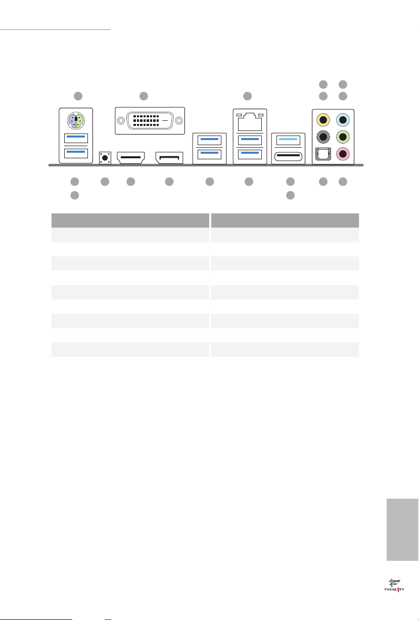
1.4 I/O Panel
1
Fatal1ty Z170 Gaming K6+ Series / Fatal1ty Z170 Gaming K6 Series
6
2 3 547
17
18
No. Description No. Description
1 PS/2 Mouse/Keyboard Port 10 USB 3.1 Type-A Port (USB31_TA _1)
2 DVI-D Port 11 USB 3.1 Type-C Port (USB31_TC_1)
3 LAN RJ-45 Port* 12 USB 3.0 Ports (USB3_34)
4 Central / Bass (Orange) 13 USB 3.0 Ports (USB3_12)
5 Rear Speaker (Black) 14 DisplayPort 1.2
6 Line In (Light Blue) 15 HDMI Port
7 Front Speaker (Lime)** 16 Clear CMOS Switch
8 Microphone (Pink) 17 Fatal1ty Mouse Port (USB3_5)
9 Optical SPDIF Out Port 18 USB 3.0 Ports (USB3_6)
1213141516
11
8910
English
9
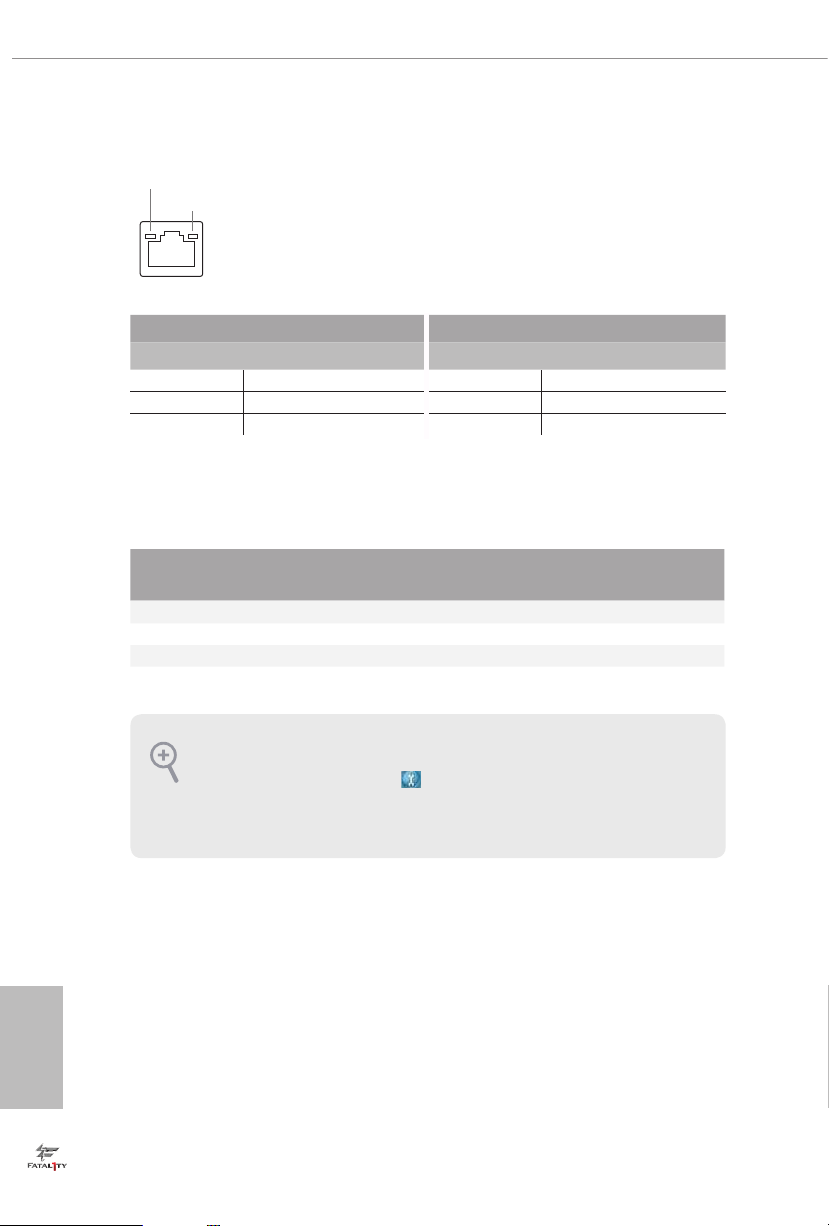
* ere are two LEDs on each LAN port. Plea se refer to the table below for the LAN port LED indications.
ACT/LINK LED
SPEED LED
LAN Por t
Activity / Link LED Speed LED
Status Description Status Description
O No Link O 10Mbps connection
Blinking Data Activity Orange 100Mbps connection
On Link Green 1Gbps connection
** If you use a 2- channel speaker, please connec t the speaker’s plug into “Front Speaker Jack”. See the table below
for connection details in a ccordance with the t ype of speaker you use.
English
Audio Output
Channels
Front Speaker
(No. 7)
Rear Speaker
(No. 5)
Central / Bass
(No. 4)
2 V -- -- --
4 V V -- --
6 V V V --
8 V V V V
To enable Multi-Streaming, you need to connect a front panel audio cable to the front
panel au dio header. Aer restarting your computer, you will nd the “Mixer” tool on your
system. Please select “Mixer ToolBox” , click “Enable playback multi-s treaming”, and
click “ok”. Choose “2CH”, “4CH”, “6CH”, or “8CH” and then you are allowed to select
“Realtek HDA Primary output” to use the Rear Speaker, Central/Bas s, and Front Speaker,
or select “Realtek HDA Audio 2nd output” to use the front panel audio.
Line In
(No. 6)
10

Fatal1ty Z170 Gaming K6+ Series / Fatal1ty Z170 Gaming K6 Series
1.5 ASRock Front USB 3.1 Panel
(for Fatal1ty Z170 Gaming K6+ Series only)
Specications
Dimension •
Controller •
Front Panel
I/O
Connector
OS
* It is recommended to insta ll the ASRock Front USB 3.1 Panel into the drive bay of
your chassis before connecting other USB devices.
75mm (W) x 42.8mm (H) x 148mm (L)
ASMedia ASM1142 Controller
1 x USB 3.1 Ty pe-A Port (10 Gb/s) (Supports ESD Protection
•
(ASRock Full Spike Protection))
* For charging Type-A USB devices, we suggest using the Type-A
connectors on your mot herboard.
1 x USB 3.1 Ty pe-C Port (10 Gb/s) (Supports ESD Protection
•
(ASRock Full Spike Protection))
* is por t supports power outputs up to 5V/3A. For charging Type-C
USB devices, the device should support Type-C sta ndards to adjust the
current because it will be dierent in Power On state (3 Amp) and Sleep
state (1 Amp).
* Some Type-C USB devices may only be charged by its own adapter.
1 x SATA Express 10 Gb/s Connector
•
1 x USB Power Connector
•
Microso® Windows® 10 64-bit / 8.1 64-bit / 7 32-bit / 7 64-bit
•
11
English
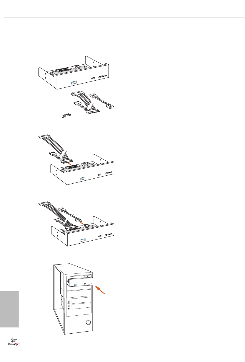
ASRock Front USB 3.1 Panel Installation Guide
Step 1
Fro
n
t
USB
3.1
Pa
n
el
F
ro
n
t
U
SB
3
.1
Pa
n
el
F
ro
n
t
U
SB
3
.1
Pa
n
e
l
Prepare the bundled ASRock Front USB 3.1 Panel,
SATA Express Cable, USB Power Cable and screws.
Step 2
Connect one end of the SATA Express Cable to the
SATA Express Connector on the ASRock Front USB
3.1 Pa nel.
Step 3
Connect one end of the USB Power Cable to the
USB Power Connector on the ASRock Front USB 3.1
Panel.
English
12
Step4
Install ASRock Front USB 3.1 Panel into the drive
bay of the chassis.
Fatal1ty Z170 Gaming K6+ Series / Fatal1ty Z170 Gaming K6 Series
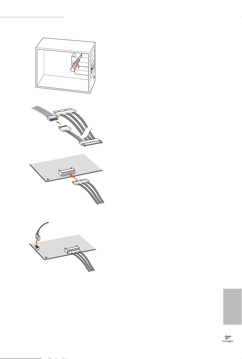
Step 5
Screw ASRock Front USB 3.1 Panel to the
drive bay with screws.
0
.
3
B
S
U
0
.
3
B
S
U
Step 6
Connect the PSU’s SATA Power Cable to
the SATA Power Connector.
Step 7
4
_
0
_
3
A
T
A
S
5
_
1
_
3
A
T
SA
1
_
0
_
P
X
E
_
A
T
SA
Cable to the SATA Express Connector on
the motherboard.
Connect the other end of the SATA Express
Step 8
Connect the other end of the USB Power
Cable to the USB 2.0 Header on the
U
S
B
3
_
4
2
_
0
_
3
A
T
A
S
3
_
1
_
3
A
T
SA
motherboard.
English
13

Chapter 2 Installation
is is an ATX form factor motherboard. Before you install the motherboard, study
the conguration of your chassis to ensure that the motherboard ts into it.
Pre-installation Precautions
Take note of the following precautions before you install motherboard components
or change any motherboard settings.
Make sure to unplug the power cord before installing or removing the motherboard
•
components. Failure to do so may cause physical injuries and damages to motherboard
components.
In order to avoid damage from static electricity to the motherboard’s components,
•
NEVER place your motherboard directly on a carpet. Also remember to use a grounded
wrist strap or touch a safety grounded object before you handle the components.
Hold components by the edges and do not touch the ICs.
•
Whenever you uninstall any components, place them on a grounded anti-static pad or
•
in the bag that comes with the components.
When placing screws to secure the motherboard to the chassis, please do not over-
•
tighten the screws! Doing so may damage the motherboard.
English
14

Fatal1ty Z170 Gaming K6+ Series / Fatal1ty Z170 Gaming K6 Series
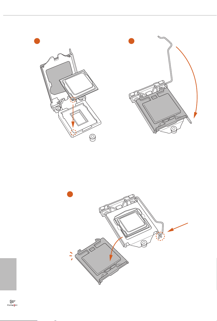
2.1 Installing the CPU
1. Before you insert the 1151-Pin CPU into th e socket , please check if the PnP cap is on the
socket, if the CPU sur face is unclean, or if the re are any bent pins in the socket . Do not
force to in sert the CPU into the socket if above situation is found. Otherwise, the CPU
will be seriously damaged.
2. Unplug all power c ables be fore installing the CPU.
1
A
B
2
English
15
3
4
English
16
5

Fatal1ty Z170 Gaming K6+ Series / Fatal1ty Z170 Gaming K6 Series
Please save and replace the cover if the processor is removed. e cove r must be placed if
you wish to return the motherboard for ae r service.
17
English
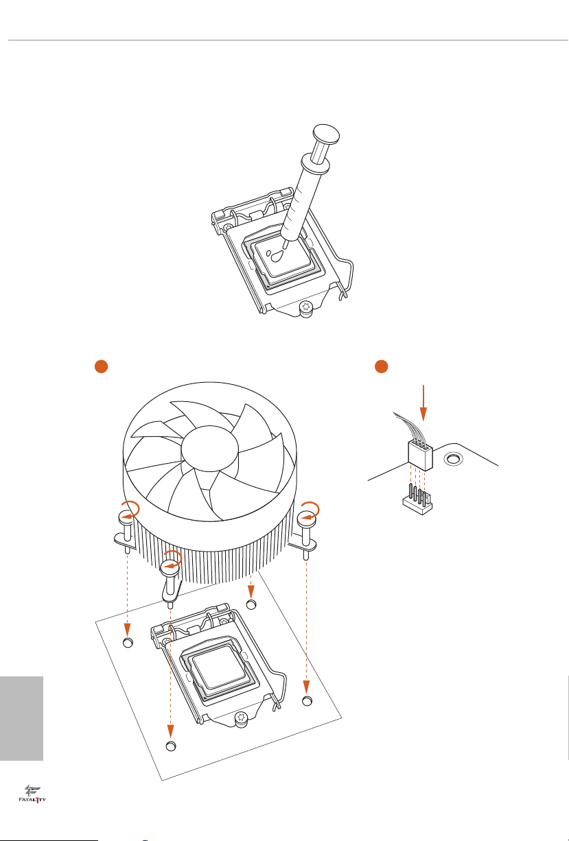
2.2 Installing the CPU Fan and Heatsink
1 2
English
18
FAN
CPU_
Fatal1ty Z170 Gaming K6+ Series / Fatal1ty Z170 Gaming K6 Series
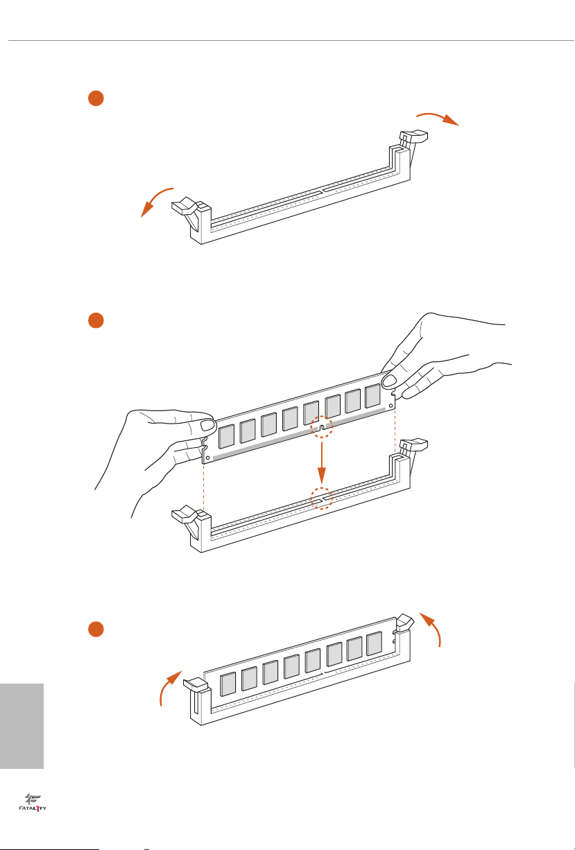
2.3 Installing Memory Modules (DIMM)
is motherboard provides four 288-pin DDR4 (Double Data Rate 4) DIMM slots,
and supports Dual Channel Memory Technology.
1. For dual channel conguration, you always need to install identical (the same brand,
speed , size and chip-type) DDR4 DIMM pairs.
2. It is unable to activate Dual Channel Me mory Technol ogy with only one or three memory
module installed.
3. It is not allowed to install a DDR, DDR2 or DDR3 memory module into a DDR4 slot;
otherwise, this mothe rboard and DI MM may be damaged.
Dual Channel Memory Conguration
Priority DDR4_A1 DDR4_A2 DDR4_B1 DDR4_B2
1 Populated Populated
2 Populated Populated
3 Populated Populated Populated Populated
e DIMM only ts in one correct orientation. It wil l cause permane nt damage to the
motherboard and the DIMM if you force the DIMM into the slot at incorrect orie ntation .
English
19
1
2
English
20
3
Fatal1ty Z170 Gaming K6+ Series / Fatal1ty Z170 Gaming K6 Series
2.4 Expansion Slots (PCI Express Slots)
ere are 6 PCI Express slots on the motherboard.
Before installing an expansion card, plea se make sure that the power supply is sw itched o
or the power cord is unplugged. Please read the documentation of the expansion card and
make necessary hardware settings for the card before you start the installation.
PCIe slots:
PCIE1 (PCIe 3.0 x1 slot) is used for PCI Express x1 lane width cards.
PCIE2 (PCIe 3.0 x16 slot) is used for PCI Express x16 lane width graphics cards.
PCIE3 (PCIe 3.0 x1 slot) is used for PCI Express x1 lane width cards.
PCIE4 (PCIe 3.0 x16 slot) is used for PCI Express x8 lane width graphics cards.
PCIE5 (PCIe 3.0 x1 slot) is used for PCI Express x1 lane width cards.
PCIE6 (PCIe 3.0 x16 slot) is used for PCI Express x4 lane width graphics cards.
PCIe Slot Congurations
PCIE2 PCIE4 PCIE6
Single Graphics Card x16 N/A N/A
Two Graphics Cards in
CrossFireX
TM
or SLITM
x8 x8 N/A
Mode
ree Graphics Cards in
3-Way CrossFireX
For a better thermal environment, please connect a ch assis fan to the moth erboard ’s chassis fan connector (CHA_FAN1, CHA_FAN2, CHA_FAN3 or CHA_ FAN4) when using
multiple graphics cards.
TM
Mode
x8 x8 x4
English
21
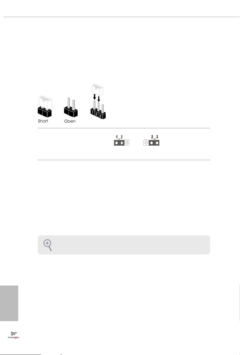
2.5 Jumpers Setup
e illustration shows how jumpers are setup. When the jumper cap is placed on
the pins, the jumper is “Short”. If no jumper cap is placed on the pins, the jumper
is “Open”. e illustration shows a 3-pin jumper whose pin1 and pin2 are “Short”
when a jumper cap is placed on these 2 pins.
Clear CMOS Jumper
(CLR MOS1)
(see p.7, No. 19)
CLRMOS1 allows you to clear the data in CMOS. To clear and reset the system
parameters to default setup, please turn o the computer and unplug the power
cord from the power supply. Aer waiting for 15 seconds, use a jumper cap to
short pin2 and pin3 on CLRMOS1 for 5 seconds. However, please do not clear the
CMOS right aer you update the BIOS. If you need to clear the CMOS when you
just nish updating the BIOS, you must boot up the system rst, and then shut it
down before you do the clear-CMOS action. Please be noted that the password,
date, time, and user default prole will be cleared only if the CMOS batter y is
removed.
Default
Clear CMOS
English
22
e Clear CMOS Switch h as the sam e function as the Cl ear CMOS jumper.
 Loading...