

Page 1

Page 2

Version 1.0
Published January 2018
Copyright©2018 ASRock INC. All rights reserved.
Copyright Notice:
No part of this documentation may be reproduced, transcribed, transmitted, or
translated in any language, in any form or by any means, except duplication of
documentation by the purchaser for backup purpose, without written consent of
ASRock Inc.
Products and corporate names appearing in this documentation may or may not
be registered trademarks or copyrights of their respective companies, and are used
only for identication or explanation and to the owners’ benet, without intent to
infringe.
Disclaimer:
Specications and information contained in this documentation are furnished for
informational use only and subject to change without notice, and should not be
constructed as a commitment by ASRock. ASRock assumes no responsibility for
any errors or omissions that may appear in this documentation.
With respect to the contents of this documentation, ASRock does not provide
warranty of any kind, either expressed or implied, including but not limited to
the implied warranties or conditions of merchantability or tness for a particular
purpose.
In no event shall ASRock, its directors, ocers, employees, or agents be liable for
any indirect, special, incidental, or consequential damages (including damages for
loss of prots, loss of business, loss of data, interruption of business and the like),
even if ASRock has been advised of the possibility of such damages arising from any
defect or error in the documentation or product.
is device complies with Part 15 of the FCC Rules. Operation is subject to the following
two conditions:
(1) this device may not cause harmful interference, and
(2) this device must accept any interference received, including interference that
may cause undesired operation.
CALIFORNIA, USA ONLY
e Lithium battery adopted on this motherboard contains Perchlorate, a toxic substance
controlled in Perchlorate Best Management Practices (BMP) regulations passed by the
California Legislature. When you discard the Lithium battery in California, USA, please
follow the related regulations in advance.
“Perchlorate Material-special handling may apply, see ww w.dtsc.ca.gov/hazardouswaste/
perchlorate”
ASRock Website: http://www.asrock.com
Page 3

AUSTRALIA ONLY
Our goods come with guarantees that cannot be excluded under the Australian Consumer
Law. You are entitled to a replacement or refund for a major failure and compensation for
any other reasonably foreseeable loss or damage caused by our goods. You are also entitled
to have the goods repaired or replaced if the goods fail to be of acceptable quality and the
failure does not amount to a major failure. If you require assistance please call ASRock Tel
: +886-2-28965588 ext.123 (Standard International call charges apply)
e terms HDMI™ and HDMI High-Denition Multimedia Interface, and the HDMI
logo are trademarks or registered trademarks of HDMI Licensing LLC in the United
States and other countries.
Page 4

Fatal1ty Story
Who knew that at age 19, I would be a World Champion PC gamer. When I was 13, I actually
played competitive billiards in professional tournaments and won four or ve games o guys
who played at the highest level. I actually thought of making a career of it, but at that young
age situations change rapidly. Because I’ve been blessed with great hand-eye coordination and
a grasp of mathematics (an important element in video gaming) I gravitated to that activity.
GOING PRO
I started professional gaming in 1999 when I entered the CPL (Cyberathlete Professional
League) tournament in Dallas and won $4,000 for coming in third place. Emerging as one
of the top players in the United States, a company interested in sponsoring me ew me to
Sweden to compete against the top 12 players in the world. I won 18 straight games, lost
none, and took rst place, becoming the number one ranked Quake III player in the world
in the process. Two months later I followed that success by traveling to Dallas and defending
my title as the world’s best Quake III player, winning the $40,000 grand prize. From there
I entered competitions all over the world, including Singapore, Korea, Germany, Australia,
Holland and Brazil in addition to Los Angeles, New York and St. Louis.
WINNING STREAK
I was excited to showcase my true gaming skills when defending my title as CPL
Champion of the year at the CPL Winter 2001 because I would be competing in a totally
dierent rst person shooter (fps) game, Alien vs. Predator II. I won that competition and
walked away with a new car. e next year I won the same title playing Unreal Tournament
2003, becoming the only three-time CPL champion of the year. And I did it playing a
different game each year, something no one else has ever done and a feat of which I am
extremely proud.
At QuakeCon 2002, I faced o against my rival ZeRo4 in one of the most highly
anticipated matches of the year, winning in a 14 to (-1) killer victory. Competing at Quakecon
2004, I became the World’s 1st Doom3 Champion by defeating Daler in a series of very
challenging matches and earning $25,000 for the victory.
Since then Fatal1ty has traveled the globe to compete against the best in the world, winning
prizes and acclaim, including the 2005 CPL World Tour Championship in New York City for
a $150,000 rst place triumph. In August 2007, Johnathan was awarded the rst ever Lifetime
Achievement Award in the four year history of the eSports-Award for “showing exceptional
sportsmanship, taking part in shaping eSports into what it is today and for being the prime
representative of this young sport. He has become the gurehead for eSports worldwide”.
Page 5

LIVIN’ LARGE
Since my rst big tournament wins, I have been a “Professional Cyberathlete”, traveling the
world and livin’ large with lots of International media coverage on outlets such as MTV,
ESPN and a 60 Minutes segment on CBS to name only a few. It's unreal - it's crazy. I’m living
a dream by playing video games for a living. I’ve always been athletic and took sports like
hockey and football very seriously, working out and training hard. is discipline helps me
become a better gamer and my drive to be the best has opened the doors necessary to become
a professional.
A DREAM
Now, another dream is being realized – building the ultimate gaming computer, made
up of the best parts under my own brand. Quality hardware makes a huge difference in
competitions…a couple more frames per second and everything gets really nice. It’s all about
getting the computer processing faster and allowing more uid movement around the maps.
My vision for Fatal1ty hardware is to allow gamers to focus on the game without worrying
about their equipment, something I’ve preached since I began competing. I don’t want to
worry about my equipment. I want to be there – over and done with - so I can focus on
the game. I want it to be the fastest and most stable computer equipment on the face of the
planet, so quality is what Fatal1ty Brand products represent.
Johnathan “Fatal1ty” Wendel
e Fatal1ty name, Fatal1ty logos and the Fatal1ty likeness are registered trademarks of Fatal1ty, Inc., and are used
under license. © 2018 Fatal1ty, Inc. All rights reserved. All other trademarks are the property of their respective
owners.
Page 6

Contents
Chapter 1 Introduction 1
1.1 Package Contents 1
1.2 Specications 2
1.3 Motherboard Layout 7
1.4 I/O Panel 9
Chapter 2 Installation 11
2.1 Installing the CPU 12
2.2 Installing the CPU Fan and Heatsink 14
2.3 Installing Memory Modules (DIMM) 23
2.4 Expansion Slots (PCI Express Slots) 26
2.5 Jumpers Setup 27
2.6 Onboard Headers and Connectors 28
2.7 Dr. Debug 34
2.8 SLITM and Quad SLITM Operation Guide 36
2.8.1 Installing Two SLITM-Ready Graphics Cards 36
2.8.2 Driver Installation and Setup 38
2.9 CrossFireXTM and Quad CrossFireXTM Operation Guide 39
2.9.1 Installing Two CrossFireXTM-Ready Graphics Cards 39
2.9.2 Driver Installation and Setup 41
2.10 M.2_SSD (NGFF) Module Installation Guide (M2_1) 42
2.11 M.2_SSD (NGFF) Module Installation Guide (M2_2) 45
Chapter 3 Software and Utilities Operation 48
Page 7

3.1 Installing Drivers 48
3.2 F-Stream 49
3.2.1 Installing F-Stream 49
3.2.2 Using F-Stream 49
3.3 ASRock Live Update & APP Shop 52
3.3.1 UI Overview 52
3.3.2 Apps 53
3.3.3 BIOS & Drivers 56
3.3.4 Setting 57
3.4 Creative SoundBlaster Cinema5 58
3.5 ASRock Polychrome RGB 59
Chapter 4 UEFI SETUP UTILITY 62
4.1 Introduction 62
4.1.1 UEFI Menu Bar 62
4.1.2 Navigation Keys 63
4.2 Main Screen 64
4.3 OC Tweaker Screen 65
4.4 Advanced Screen 68
4.4.1 CPU Conguration 69
4.4.2 North Bridge Conguration 70
4.4.3 South Bridge Conguration 71
4.4.4 Storage Conguration 72
4.4.5 Super IO Conguration 73
4.4.6 ACPI Conguration 74
Page 8

4.4.7 Trusted Computing 75
4.4.8 AMD CBS 76
4.4.9 AMD PBS 84
4.5 Tools 85
4.6 Hardware Health Event Monitoring Screen 87
4.7 Security Screen 90
4.8 Boot Screen 91
4.9 Exit Screen 93
Page 9

Fatal1ty X470 Gaming K4 Series
Chapter 1 Introduction
ank you for purchasing ASRock Fatal1ty X470 Gaming K4 Series motherboard,
a reliable motherboard produced under ASRock ’s consistently stringent quality
control. It delivers excellent performance with robust design conforming to
ASRock’s commitment to quality and endurance.
In this documentation, Chapter 1 and 2 contains the introduction of the
motherboard and step-by-step installation guides. Chapter 3 contains the operation
guide of the soware and utilities. Chapter 4 contains the conguration guide of
the BIOS setup.
Becau se the motherboard specications and the BIOS soware might be updated, the
content of this documentation will be subject to change without notice. In case any
modications of this documentation occur, the updated version will be available on
ASRock’s website w ithout f urther notice. If you require technical support relate d to
this motherboard, please vi sit our website for s pecic information about the model
you are using. You may nd the l atest VGA cards and CPU suppor t list on ASRock’s
website a s well. ASRock website ht tp://www.a srock.com.
1.1 Package Contents
ASRock Fatal1ty X470 Gaming K4 Series Motherboard (ATX Form Factor)
•
ASRock Fatal1ty X470 Gaming K4 Series Quick Installation Guide
•
ASRock Fatal1ty X470 Gaming K4 Series Support CD
•
1 x I/O Panel Shield
•
4 x Serial ATA (SATA) Data Cables (Optional)
•
1 x ASRock SLI_HB_Bridge_2S Card (Optional)
•
2 x Screws for M.2 Sockets (Optional)
•
English
1
Page 10

1.2 Specications
Platform
CPU
Chipset
Memory
•
•
•
•
•
•
•
•
•
•
•
•
* For Ryzen Series CPUs (Raven Ridge), ECC is only supported
with PRO CPUs.
* Please refer to Memory Support List on ASRock’s website for
more information. (http://www.asrock.com/)
* Please refer to page 23 for DDR4 UDIMM maximum
frequency support.
•
•
ATX Form Factor
2oz Copper PCB
Supports AMD AM4 Socket Ryzen Series CPUs (Summit
Ridge, Raven Ridge and Pinnacle Ridge)
Digi Power design
12 Power Phase design
Supports 105W Water Cooling (Pinnacle Ridge); Supports
95W Water Cooling (Summit Ridge); Supports 65W Water
Cooling (Raven Ridge)
AMD Promontory X470
Dual Channel DDR4 Memory Technology
4 x DDR4 DIMM Slots
AMD Ryzen series CPUs (Pinnacle Ridge) support DDR4
3466+(OC)/3200(OC)/2933/2667/2400/2133 ECC & non-
ECC, un-buered memory*
AMD Ryzen series CPUs (Summit Ridge) support DDR4
3466+(OC)/3200(OC)/2933(OC)/2667/2400/2133 ECC &
non-ECC, un-buered memory*
AMD Ryzen series CPUs (Raven Ridge) support DDR4
3466+(OC)/3200(OC)/2933(OC)/2667/2400/2133 non-ECC,
un-buered memory*
Max. capacity of system memory: 64GB
15μ Gold Contact in DIMM Slots
English
2
Expansion
Slot
2 x PCI Express 3.0 x16 Slots (single at x16 (PCIE1); dual at
•
x8 (PCIE1) / x8 (PCIE4))*
* Supports NVMe SSD as boot disks
4 x PCI Express 2.0 x1 Slots
•
Page 11

Graphics
Audio
Fatal1ty X470 Gaming K4 Series
Supports AMD Quad CrossFireXTM and CrossFireXTM
•
Supports NVIDIA® Quad SLITM and SLI
•
15μ Gold Contact in VGA PCIe Slot (PCIE1)
•
Integrated AMD RadeonTM Vega Series Graphics in Ryzen
•
Series APU*
* Actual support may vary by CPU
DirectX 12, Pixel Shader 5.0
•
Max. shared memory 2GB
•
Supports HDMI with max. resolution up to 4K x 2K
•
(4096x2160) @ 30Hz
Supports Auto Lip Sync, Deep Color (12bpc), xvYCC and
•
HBR (High Bit Rate Audio) with HDMI Port (Compliant
HDMI monitor is required)
Supports HDCP with HDMI Port
•
Supports 4K Ultra HD (UHD) playback with HDMI Port
•
7.1 CH HD Audio with Content Protection (Realtek
•
ALC1220 Audio Codec)
Premium Blu-ray Audio support
•
Supports Surge Protection
•
Nichicon Fine Gold Series Audio Caps
•
120dB SNR DAC with Dierential Amplier
•
NE5532 Premium Headset Amplier for Front Panel Audio
•
Connector (Supports up to 600 Ohm headsets)
Pure Power-In
•
Direct Drive Technology
•
PCB Isolate Shielding
•
Impedance Sensing on Line Out port
•
Individual PCB Layers for R/L Audio Channel
•
Gold Audio Jacks
•
Supports Creative SoundBlaster Cinema5
•
TM
LAN
Gigabit LAN 10/100/1000 Mb/s
•
GigaLAN Intel® I211AT
•
Supports Wake-On-LAN
•
Supports Lightning/ESD Protection
•
Supports Energy Ecient Ethernet 802.3az
•
Supports PXE
•
English
3
Page 12

Rear Panel
I/O
Storage
1 x PS/2 Mouse/Keyboard Port
•
1 x HDMI Port
•
1 x Optica l SPDIF Out Port
•
1 x USB 3.1 Gen2 Type-A Port (10 Gb/s) (Supports ESD
•
Protection)
1 x USB 3.1 Gen2 Type-C Port (10 Gb/s) (Supports ESD
•
Protection)
6 x USB 3.1 Gen1 Ports (Supports ESD Protection)
•
* 1 x Fatal1ty Mouse Port (USB 3.1 Gen1) is included
1 x RJ-45 LAN Port with LED (ACT/LINK LED and SPEED
•
LED)
HD Audio Jacks: Rear Speaker / Central / Bass / Line in /
•
Front Speaker / Microphone (Gold Audio Jacks)
6 x SATA3 6.0 Gb/s Connectors, support RAID (RAID 0,
•
RAID 1 and RAID 10), NCQ, AHCI and Hot Plug
1 x Ultra M.2 Socket (M2_1), supports M Key type
•
2230/2242/2260/2280/22110 M.2 SATA3 6.0 Gb/s module
and M.2 PCI Express module up to Gen3 x4 (32 Gb/s)*
1 x M.2 Socket (M2_2), supports M Key type
•
2230/2242/2260/2280 M.2 SATA3 6.0 Gb/s module and M.2
PCI Express module up to Gen2 x2 (10 Gb/s)*
* Supports NVMe SSD as boot disks
* Supports ASRock U.2 Kit
English
4
Connector
1 x COM Port Header
•
1 x TPM Header
•
1 x Power LED and Speaker Header
•
1 x AMD Fan LED Header
•
* e AMD Fan LED Header supports LED strips of maximum
load of 3A (36W) and length up to 2.5M.
1 x RGB LED Header
•
* Supports in total up to 12V/3A, 36W LED Strip
1 x Addressable LED Header
•
* Supports in total up to 5V/3A, 15W LED Strip
1 x CPU Fan Connector (4-pin)
•
* e CPU Fan Connector supports the CPU fan of ma ximum
1A (12W) fan power.
1 x CPU/Water Pump Fan Connector (4-pin) (Smart Fan
•
Speed Control)
Page 13

Fatal1ty X470 Gaming K4 Series
* e CPU/Water Pump Fan supports the water cooler fan of
maximum 2A (24W) fan power.
3 x Chassis/Water Pump Fan Connectors (4-pin) (Smart Fan
•
Speed Control)
* e Chassis/Water Pump Fan supports the water cooler fan of
maximum 2A (24W) fan power.
* CPU_FAN2/WP, CHA_FAN1/WP, CHA_FAN2/WP and
CHA_FAN3/WP can auto detect if 3-pin or 4-pin fan is in use.
1 x 24 pin ATX Power Connector (Hi-Density Power Con-
•
nector)
1 x 8 pin 12V Power Connector (Hi-Density Power Connec-
•
tor)
1 x 4 pin 12V Power Connector (Hi-Density Power Connec-
•
tor)
1 x Front Panel Audio Connector
•
1 x AMD LED Fan USB Header
•
2 x USB 2.0 Headers (Support 4 USB 2.0 ports) (Supports
•
ESD Protection)
2 x USB 3.1 Gen1 Headers (Support 4 USB 3.1 Gen1 ports)
•
(Supports ESD Protection)
1 x Dr. Debug with LED
•
BIOS
Feature
Hardware
Monitor
AMI UEFI Legal BIOS with GUI support
•
Supports “Plug and Play”
•
ACPI 5.1 compliance wake up events
•
Supports jumperfree
•
SMBIOS 2.3 support
•
CPU, VCORE_NB, DRAM, VPPM, PCH 1.05V, +1.8V,
•
VDDP, PROM 2.5V, Voltage Multi-adjustment
Temperature Sensing: CPU, CPU/Water Pump, Chassis/Wa-
•
ter Pump Fans
Fan Tachometer: CPU, CPU/Water Pump, Chassis/Water
•
Pump Fans
Quiet Fan (Auto adjust chassis fan speed by CPU tempera-
•
ture): CPU, CPU/Water Pump, Chassis/Water Pump Fans
Fan Multi-Speed Control: CPU, CPU/Water Pump, Chassis/
•
Water Pump Fans
Voltage monitoring: +12V, +5V, +3.3V, CPU Vcore, VCORE_
•
NB, DRAM, PCH 1.05V, +1.8V, VDDP
English
5
Page 14
Microso® Windows® 10 64-bit
OS
Certications
* For detailed product information, please visit our website: http://ww w.asrock.com
Please realize that the re is a certain r isk involved with overclo cking, including
adjusting the setting in the BIOS, applying Untied Overclocking Technol ogy, or using
third-party overclocking tool s. Overclocking may aect your system’s stability, or
even cause dam age to the components and devices of your system. It should be done
at your own risk and expense. We are not responsible for poss ible damage caused by
overclocking.
•
FCC, CE
•
ErP/EuP ready (ErP/EuP ready power supply is required)
•
English
6
Page 15
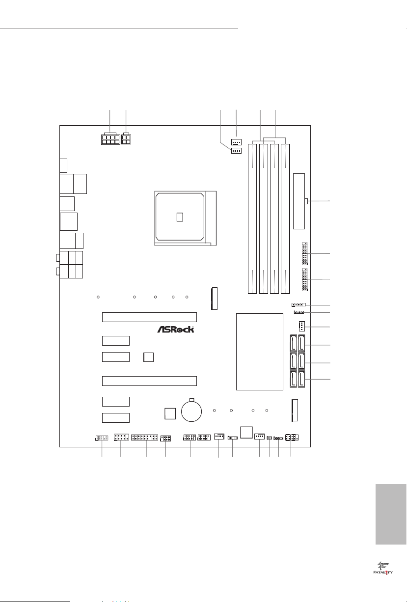
1.3 Motherboard Layout
DDR4 _A2 (64 bit, 288- pin modu le)
DDR4 _A1 (64 bit, 288- pin modu le)
DDR4 _B2 (64 bit, 288- pin modu le)
DDR4 _B1 (64 bit, 288- pin modu le)
ATXP WR 1
PCI E1
Top:
Central/Bass
Center:
REAR SPK
Top:
LINE IN
Center:
FRONT
Bottom:
Optical
SPDIF
Bottom:
MIC I N
PCI E4
HDLED RE SET
PLED PWRBTN
PANEL1
1
1
SPK_PLE D1
COM1
1
1
HD_AUDI O1
X470 Gami ng K4
SATA3_3_4
SATA3_1_2
6
12
13
14
USB_1_2
1
21
19
USB_3_4
1
22
25
26
SATA3_5_6
1
5
4
24
Dr.
Debug
15
CMOS
Batt ery
M2_1
M2_2
USB3_7_ 8
1
23
CPU_FAN1
7
8
9
10
11
1
TPMS1
Ult ra M .2
PCIe G en3 x4
FATAL TY
1
CHA_FAN1 /WP
3
2
USB3_9_ 10
1
AMD_FAN_L ED1
1
BIOS
ROM
RoH S
PCI E5
CHA_FAN2 /WP
16
1
USB_5
RGB_LED1
1
Super
I/O
PCI E6
CPU_FAN2 /WP
CHA_FAN3 /WP
20
Top:
RJ-45
USB 3.1G en1
T:USB 5
B:U SB6
USB 3.1 Gen2
T:US B3_TA_1
B: USB3_T C_1
USB 3.1 Gen1
T:US B3
B: U SB4
18
17
ADDR_LED 1
1
AMD
Promon to ry
X470
SOCKE T AM 4
HDMI1
PS2
Keybo ard/
Mouse
USB3 .1G en1
T:USB 1
B:U S B2
ATX12V1 ATX12 V2
CLRCMOS1
1
PCI E2
PCI E3
27
Fatal1ty X470 Gaming K4 Series
English
7
Page 16

No. Description
1 ATX 12V Power Connector (ATX12V1)
2 ATX 12V Power Connector (ATX12V2)
3 CPU Fan Connector (CPU_FAN1)
4 CPU/Water Pump Fan Connector (CPU_FAN2/WP)
5 2 x 288-pin DDR4 DIMM Slots (DDR4_A1, DDR4_B1)
6 2 x 288-pin DDR4 DIMM Slots (DDR4_A2, DDR4_B2)
7 ATX Power Connector (ATXPWR1)
8 USB 3.1 Gen1 Header (USB3_9_10)
9 USB 3.1 Gen1 Header (USB3_7_8)
10 AMD LED Fan USB Header (USB_5)
11 AMD Fan LED Header (AMD_FAN_LED1)
12 Chassis/Water Pump Fan Connector (CHA_FAN1/WP)
13 SATA3 Connectors (SATA3_5_6)
14 SATA3 Connectors (SATA3_3_4)
15 SATA3 Connectors (SATA3_1_2)
16 System Panel Header (PANEL1)
17 RGB LED Header (RGB_LED1)
18 Clear CMOS Jumper (CLRCMOS1)
19 Chassis/Water Pump Fan Connector (CHA_FAN2/WP)
20 Addressable LED Header (ADDR_LED1)
21 Chassis/Water Pump Fan Connector (CHA_FAN3/WP)
22 USB 2.0 Header (USB_1_2)
23 USB 2.0 Header (USB_3_4)
24 Power LED and Speaker Header (SPK_PLED1)
25 TPM Header (TPMS1)
26 COM Port Header (COM1)
27 Front Panel Audio Header (HD_AUDIO1)
English
8
Page 17
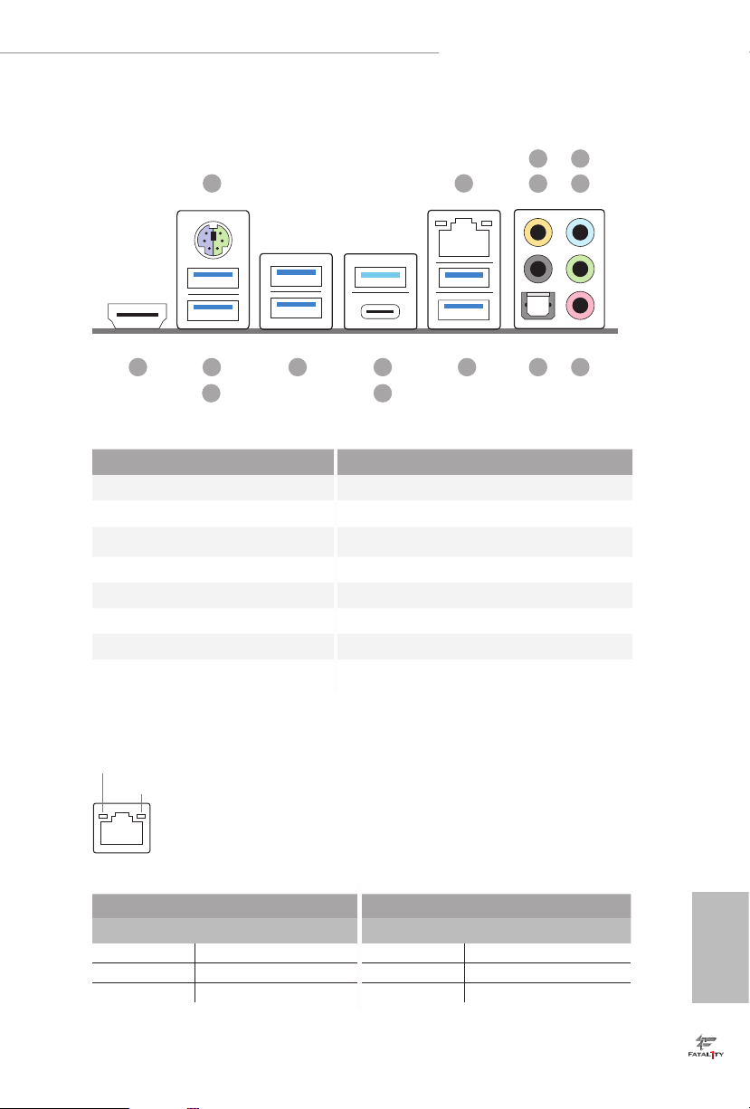
1.4 I/O Panel
Fatal1ty X470 Gaming K4 Series
5
1
2
436
12 91015 13
14
No. Description No. Description
1 PS/2 Mouse/Keyboard Port 9 USB 3.1 Gen1 Ports (USB3_5_6)
2 LAN RJ-45 Port* 10 USB 3.1 Gen2 Type-A Port (USB3_TA_1)
3 Central / Bass (Orange) 11 USB 3.1 Gen2 Type-C Port (USB3_TC_1)
4 Rear Speaker (Black) 12 USB 3.1 Gen1 Ports (USB3_3_4)
5 Line In (Light Blue) 13 Fatal1ty Mouse Port (USB3_1)
6 Front Speaker (Lime)** 14 USB 3.1 Gen1 Port (USB3_2)
7 Microphone (Pink) 15 HDMI Port (HDMI1)
8 Optica l SPDIF Out Port
* ere are two LEDs on each LAN port. Please refer to the table below for the LAN port LED indications .
ACT/LINK L ED
SPEED LE D
LAN Por t
11
78
Activity / Link LED Speed LED
Status Description Status Description
O No Link O 10Mbps connection
Blinking Data Activity Orange 100Mbps connection
On Link Green 1Gbps connection
English
9
Page 18

** If you use a 2- channel speaker, plea se connect the speake r’s plug into “Front Speaker Jack”. See the table below
for connection d etails in accordance w ith the type of speaker you use.
Audio Output
Channels
2 V -- -- --
4 V V -- --
6 V V V --
8 V V V V
Front Speaker
(No. 6)
Rear Speaker
(No. 4)
Central / Bass
(No. 3)
Line In
(No. 5)
English
10
Page 19

Fatal1ty X470 Gaming K4 Series
Chapter 2 Installation
is is an ATX form factor motherboard. Before you install the motherboard, study
the conguration of your chassis to ensure that the motherboard ts into it.
Pre-installation Precautions
Take note of the following precautions before you install motherboard components
or change any motherboard settings.
Make sure to unplug the power cord before installing or removing the motherboard.
•
Failure to do so may cause physical injuries to you and damages to motherboard
components.
In order to avoid damage from static electricity to the motherboard’s components,
•
NEVER place your motherboard directly on a carpet. Also remember to use a grounded
wrist strap or touch a safety grounded object before you handle the components.
Hold components by the edges and do not touch the ICs.
•
Whenever you uninstall any components, place them on a grounded anti-static pad or
•
in the bag that comes with the components.
When placing screws to secure the motherboard to the chassis, please do not over-
•
tighten the screws! Doing so may damage the motherboard.
11
English
Page 20
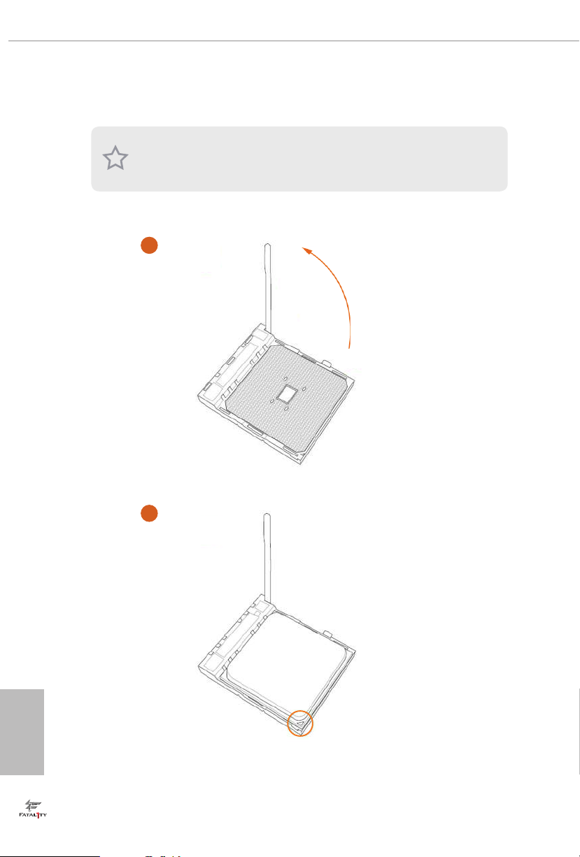
2.1 Installing the CPU
Unplug all power cables be fore installing the CPU.
1
English
12
2
Page 21

Fatal1ty X470 Gaming K4 Series
3
13
English
Page 22
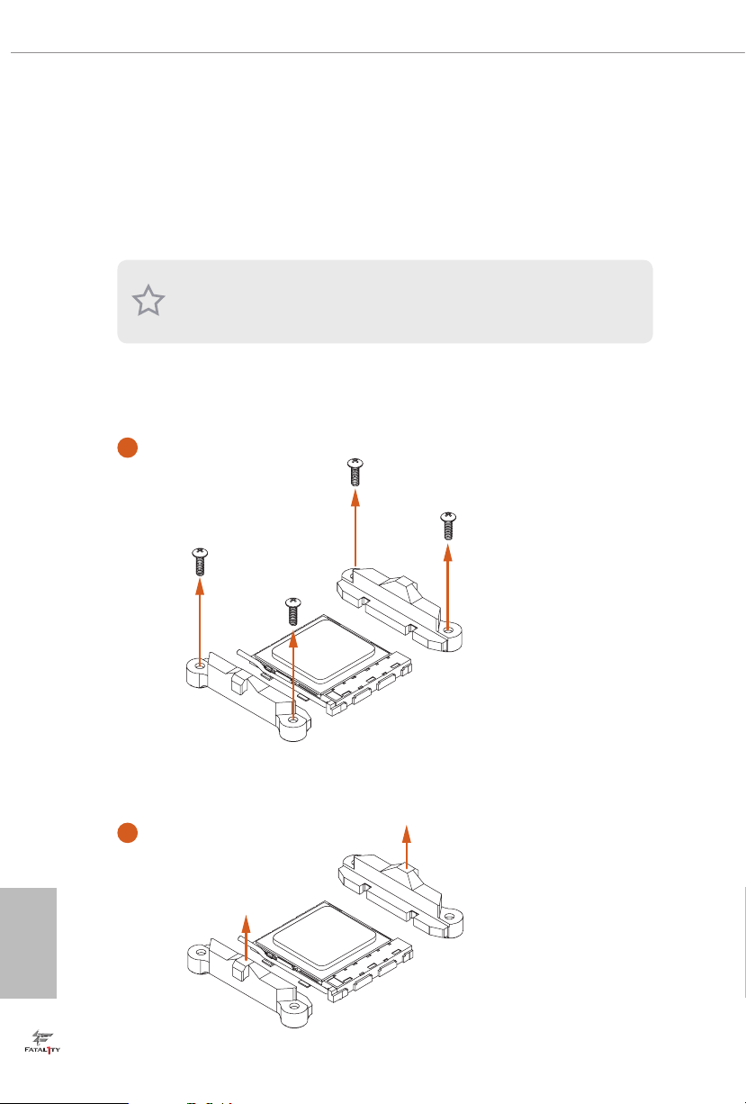
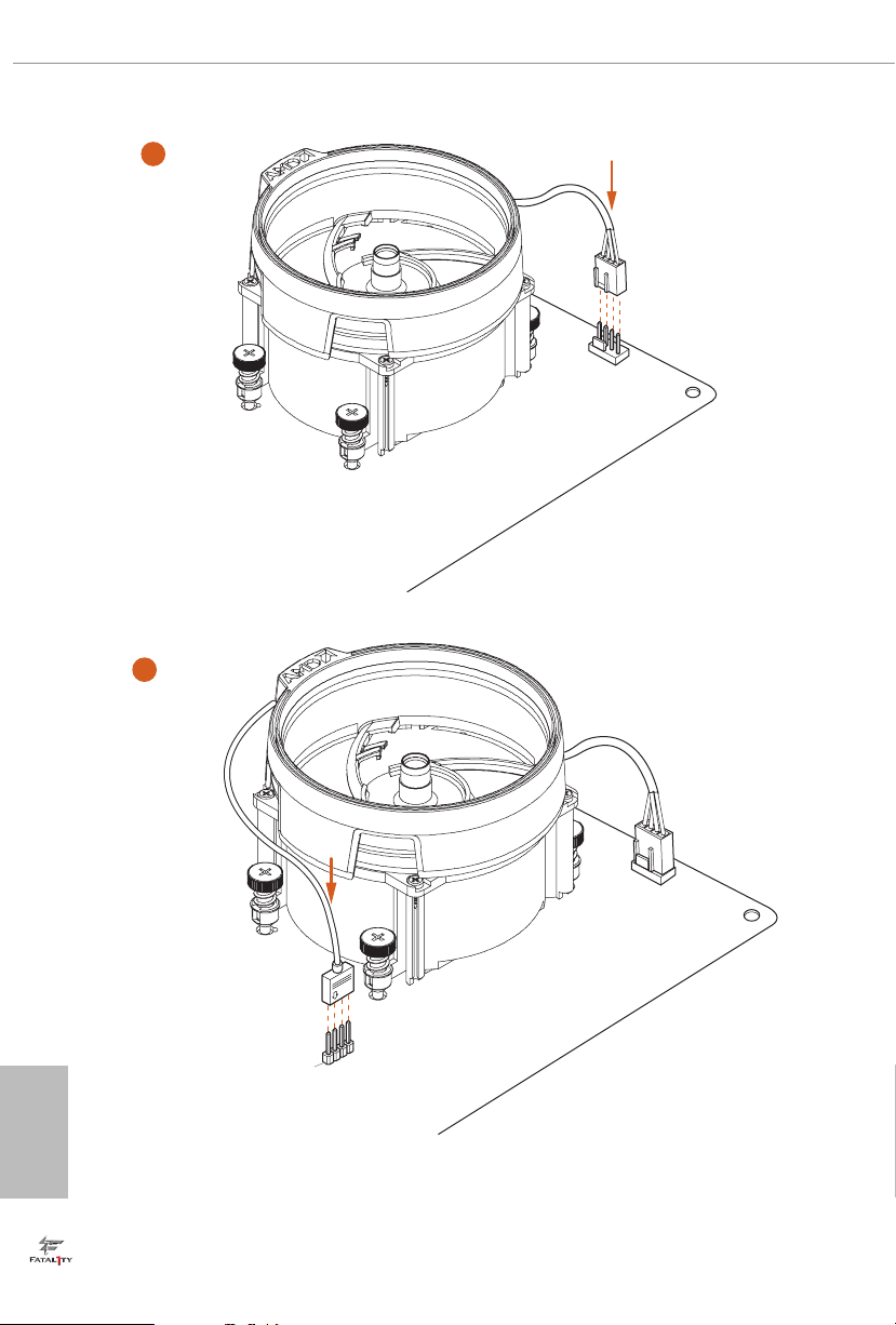
2.2 Installing the CPU Fan and Heatsink
Aer you install the CPU into this motherboard, it is necessary to install a larger
heatsink and cooling fan to dissipate heat. You also need to spray thermal grease
between the CPU and the heatsink to improve heat dissipation. Ma ke sure that the
CPU and the heatsink are securely fastened and in good contact with each other.
Please turn o the power or remove the power cord before changing a CPU or heatsink.
Installing the CPU Box Cooler SR1
1
English
14
2
Page 23
Fatal1ty X470 Gaming K4 Series
3
4
1
N
FA
_
U
P
C
English
15
Page 24
Installing the AM4 Box Cooler SR2
1
2
English
16
Page 25
Fatal1ty X470 Gaming K4 Series
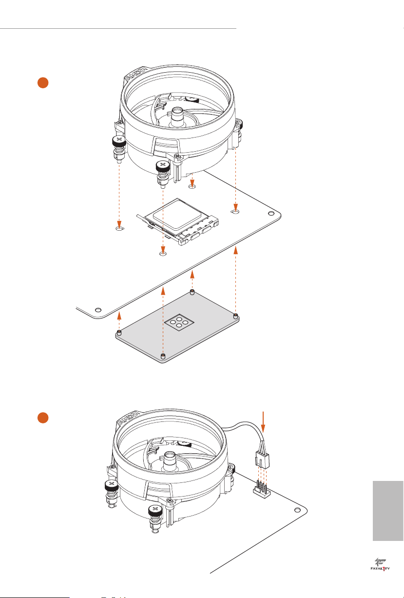
3
17
English
Page 26
4
1
N
FA
_
U
P
C
5
4-pin FAN cable
English
18
RGB LED Cable
1
N
FA
CPU_
1
D
E
L
_
N
FA
_
D
AM
+12V
*e diagram shown here are for reference only. Please refer to page 32 for the orientation of
AMD Fan LED Header (AMD_FAN_LED1).
Page 27
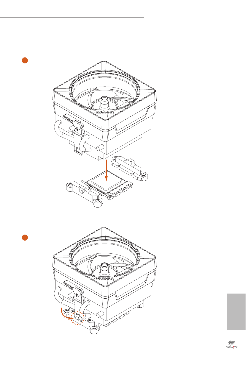
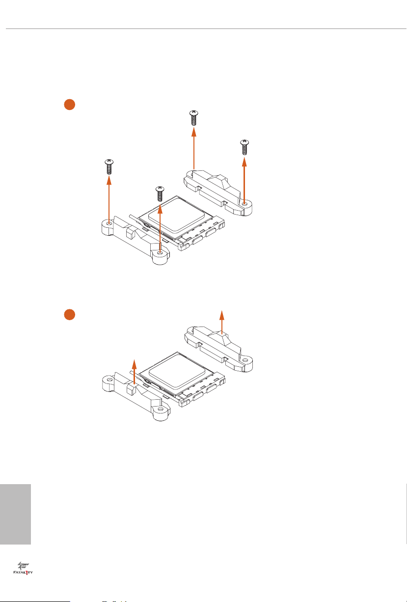
Installing the AM4 Box Cooler SR3
1
Fatal1ty X470 Gaming K4 Series
2
English
19
Page 28
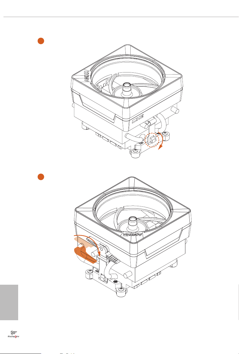
3
4
English
20
Page 29
Fatal1ty X470 Gaming K4 Series
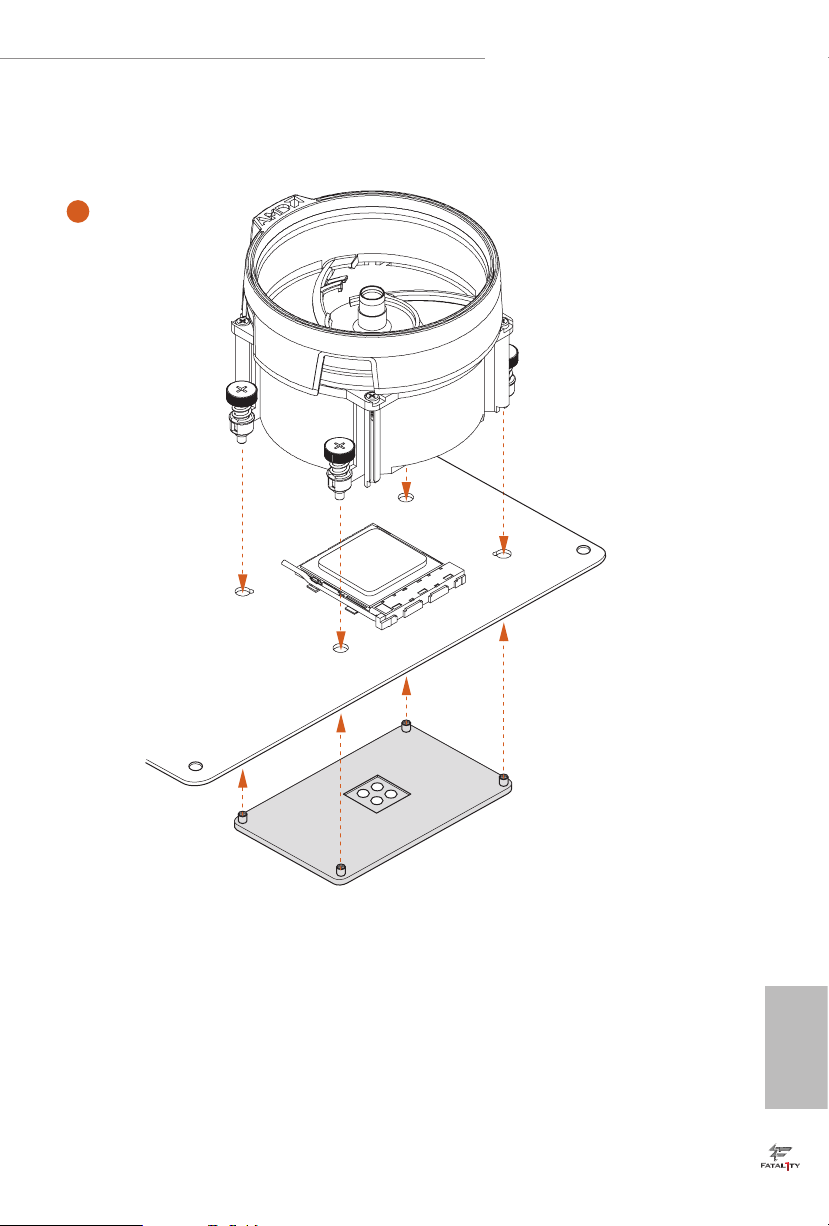
5
CPU_FAN1
21
English
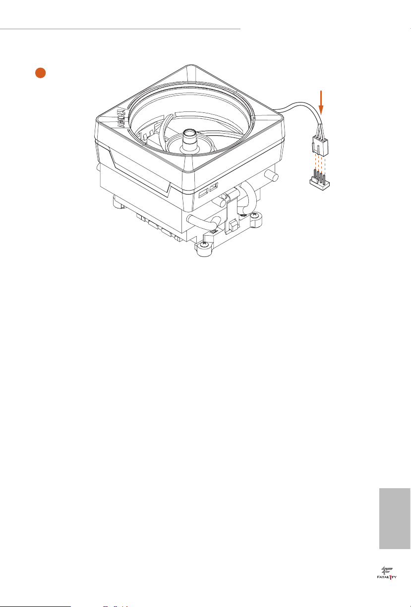
Page 30
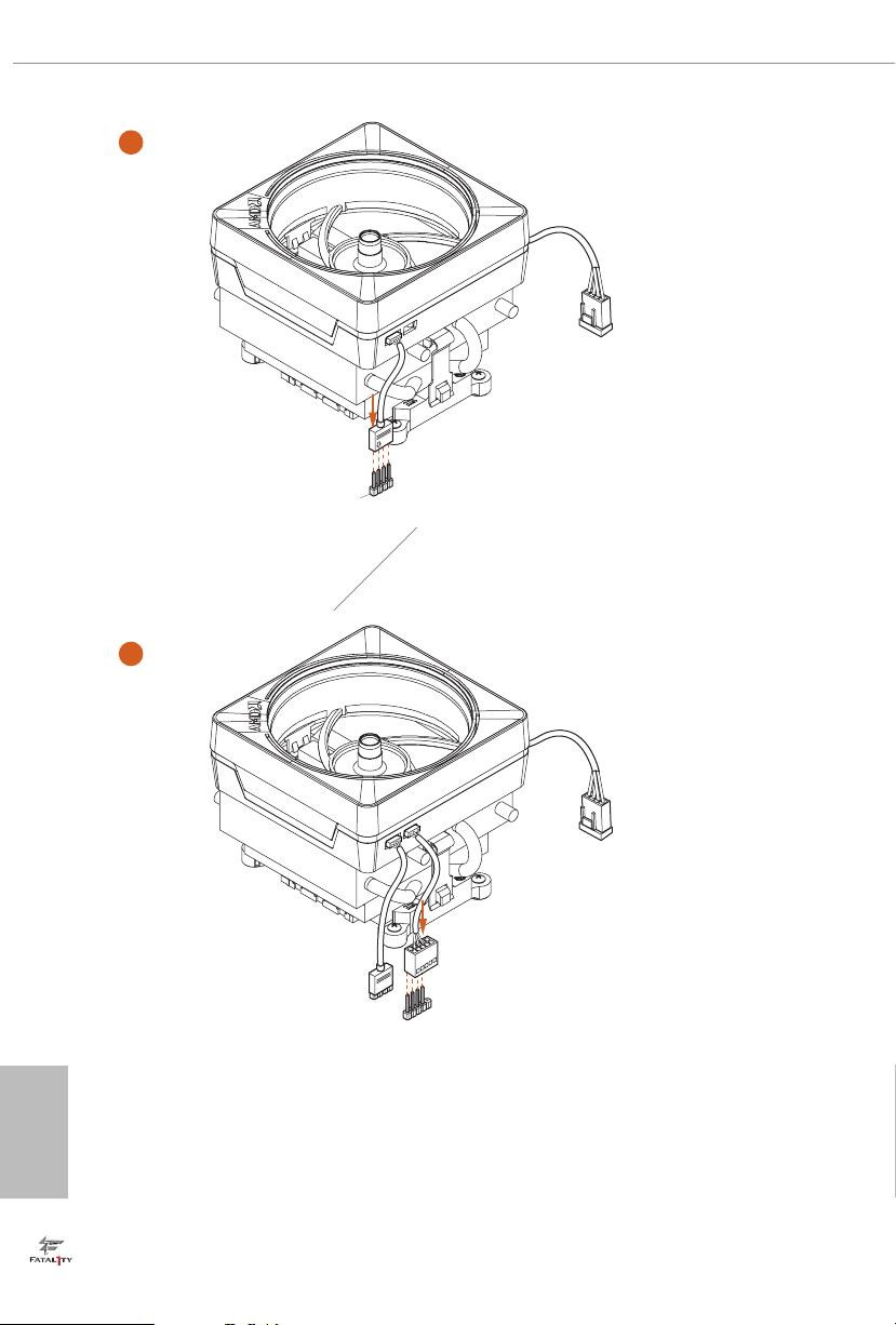
6
1
N
FA
_
U
P
C
1
D
E
L
_
N
FA
_
D
AM
+12V
or
7
1
N
FA
_
U
P
C
1
D
E
L
_
N
FA
_
D
AM
5
_
B
S
U
English
Please note that only one cable should be used at a time in this step.
If you select AMD_FAN_LED1, please install ASRock utility "ASRock Polychrome RGB".
If you select USB connector, please install AMD utility "SR3 Settings So ware".
*e diagram shown here are for reference only. Please refer to page 32 for the orientation of AMD Fan
LED Header (AMD_FAN_LED1) and page 29 for the orientation of AMD LED Fan USB Header (USB_5).
22
Page 31

Fatal1ty X470 Gaming K4 Series
2.3 Installing Memory Modules (DIMM)
is motherboard provides four 288-pin DDR4 (Double Data Rate 4) DIMM slots,
and supports Dual Channel Memory Technology.
1. For dual channel conguration, you always need to install identica l (the same
brand, speed , size and chip-type) DDR4 DIMM pairs.
2. It is unable to activate Dual Channel Memor y Technology with only one or three
memor y module installed.
3. It is not allowed to install a DDR, DDR2 or DDR3 memory module into a DDR4
slot; otherwise, this motherboard and DIMM may be damaged.
DDR4 UDIMM Maximum Frequency Support
Ryzen Series CPUs (Pinnacle Ridge):
UDIMM Memory Slot
A1 A2 B1 B2
- SR - - 2933
- DR - - 2400
- SR - SR 2933
- DR - DR 2400
SR SR SR SR 2133
SR/DR DR SR/DR DR 1866
Frequency
(Mhz)
English
23
Page 32

Ryzen Series CPUs (Summit Ridge):
UDIMM Memory Slot
A1 A2 B1 B2
- SR - - 2667
- DR - - 2667
- SR - SR 2667
- DR - DR 2400-2667
SR SR SR SR 2133-2400
SR/DR DR SR/DR DR 1866-2133
Frequency
(Mhz)
Ryzen Series CPUs (Raven Ridge):
UDIMM Memory Slot
A1 A2 B1 B2
- SR - - 2933
- DR - - 2667
- SR - SR 2667
- DR - DR 2400
SR SR SR SR 2133
SR/DR DR SR/DR DR 1866
Frequency
(Mhz)
English
24
SR: Single rank DIMM, 1Rx4 or 1R x8 on DIMM module label
DR: Dua l ran k DIMM, 2Rx4 or 2R x8 on DIMM module label
Page 33

Fatal1ty X470 Gaming K4 Series
e DIMM only ts in one correct orientation. It will cause permanent dam age to
the mothe rboard and the DIMM if you force the DIMM into the slot at incor rect
orientation .
1
2
3
English
25
Page 34

2.4 Expansion Slots (PCI Express Slots)
ere are 6 PCI Express slots on the motherboard.
Before installing an ex pansion card, please make sure that the power supply is
switched o or the power cord is unplugged. Plea se read the documentation of the
expan sion card and mak e necessary hardware settings for the card before you start
the installation.
PCIe slots:
PCIE1 (PCIe 3.0 x16 slot) is used for PCI Express x16 lane width graphics cards.
PCIE2 (PCIe 2.0 x1 slot) is used for PCI Express x1 lane width cards.
PCIE3 (PCIe 2.0 x1 slot) is used for PCI Express x1 lane width cards.
PCIE4 (PCIe 3.0 x16 slot) is used for PCI Express x8 lane width graphics cards.
PCIE5 (PCIe 2.0 x1 slot) is used for PCI Express x1 lane width cards.
PCIE6 (PCIe 2.0 x1 slot) is used for PCI Express x1 lane width cards.
PCIe Slot Congurations
Ryzen series CPUs:
PCIE1 PCIE4
Single Graphics Card x16 N/A
English
26
Two Graphics Cards in
CrossFireXTM or SLITM
x8 x8
Mode
For a better ther mal environment, ple ase connect a ch assi s fan to the motherboard’s
chassis fan connector (CHA_ FAN1, CHA_ FA N2 or CHA_FAN3) when u sing multiple graphics cards.
Page 35

Fatal1ty X470 Gaming K4 Series
2.5 Jumpers Setup
e illustration shows how jumpers are setup. When the jumper cap is placed on
the pins, the jumper is “Short”. If no jumper cap is placed on the pins, the jumper
is “Open”. e illustration shows a 3-pin jumper whose pin1 and pin2 are “Short”
when a jumper cap is placed on these 2 pins.
Clear CMOS Jumper
(CLRCMOS1)
(see p.7, No. 18)
CLRCMOS1 allows you to clear the data in CMOS. To clear and reset the system
parameters to default setup, please turn o the computer and unplug the power
cord from the power supply. Aer waiting for 15 seconds, use a jumper cap to
short the pins on CLRCMOS1 for 5 seconds. However, please do not clear the
CMOS right aer you update the BIOS. If you need to clear the CMOS when you
just nish updating the BIOS, you must boot up the system rst, and then shut it
down before you do the clear-CMOS action. Please be noted that the password,
date, time, and user default prole will be cleared only if the CMOS battery is
removed. Please remember toremove the jumper cap aer clearing the CMOS.
2-pin Jumper
27
English
Page 36

2.6 Onboard Headers and Connectors
Onboard headers and connectors are NOT jumpers. Do NOT place jumper caps over
these header s and connectors. Placing jumper caps over the headers and connectors
will cause permanent damage to the motherboard.
System Panel Header
(9-pin PANEL1)
(see p.7, No. 16)
PWRBTN (Power Switch):
Connec t to the power switch on the chassi s front panel. You may congure the way to
turn o your system using the power switch.
RESET (Reset Switch):
Connec t to the reset switch on the chassi s front panel. P ress the reset sw itch to restart
the computer if the compute r freezes and fails to perform a normal restart.
PLED (Syste m Power LED):
Connec t to the power status indicator on the chassis front panel. e LED i s on when
the system is ope rating. e LED keeps blinking when the system i s in S1/S3 sleep
state. e LED is o when the system is in S4 sleep state or powered o (S5).
HDLED (Ha rd Drive Activity LED):
Connec t to the hard drive ac tivity LED on the chassis front panel. e LED is on
when the hard drive i s reading or writing data.
e front panel de sign may dier by chassis. A front pane l module mainly consists
of power switch , reset switch, power LED, hard dr ive activity LED, speak er and etc.
When connecting your chassis front panel module to this head er, make sure the wire
assig nments and the pin assig nments are matched correctly.
1
PLE D+
PLE D-
HDL ED-
HDL ED+
PWR BTN #
GND
RES ET#
GND
GND
Connect the power
switch, reset switch and
system status indicator on
the chassis to this header
according to the pin
assignments below. Note
the positive and negative
pins before connecting
the cables.
English
28
Page 37

Fatal1ty X470 Gaming K4 Series
PLE D-
Power LED and Speaker
Header
(7-pin SPK_PLED1)
(see p.7, No. 24)
Serial ATA3 Connectors
(SATA3_1_2:
see p.7, No. 15)
(SATA3_3_4:
see p.7, No. 14)
(SATA3_5_6:
see p.7, No. 13)
AMD LED Fan USB
Header
(4-pin USB_5)
(see p.7, No. 10)
DUM MY
+5V
1
PLE D+
SATA3_5
SATA3_3SATA3_1
1
USB _P WR
SPE AK ER
DUM MY
PLE D+
P-
P+
GND
Please connect the
chassis power LED and
the chassis speaker to this
header.
ese six SATA3
connectors support SATA
data cables for internal
SATA3_6
storage devices with up to
6.0 Gb/s data transfer rate.
SATA3_4SATA3_2
is header is used for
connecting the USB
connector on the AMD
SR3 Heatsink.
USB 2.0 Headers
((9-pin USB_1_2)
(see p.7, No. 22)
(9-pin USB_3_4)
(see p.7, No. 23)
USB 3.1 Gen1 Header
(19-pin USB3_7_8)
(see p.7, No. 9)
(19-pin USB3_9_10)
(see p.7, No. 8)
USB _PW R
1
USB _PW R
Vbus
IntA _PA_S SRX-
IntA _PA_S SRX+
GND
IntA _PA_S STX-
IntA _PA_S STX+
GND
IntA _PA_D -
IntA _PA_D +
P-
P+
GND
DUM MY
on this motherboard.
Each USB 2.0 header can
support two ports.
ere are two headers
GND
P+
P-
VbusVbus
IntA _PB_ SSRX -
IntA _PB_ SSRX +
GND
IntA _PB_ SSTX -
IntA _PB_ SSTX +
GND
IntA _PB_ D-
IntA _PB_ D+
Dumm y
1
ere are two headers on
this motherboard. Each
USB 3.1 Gen1 header can
support two ports.
English
29
Page 38

Front Panel Audio Header
GND
FAN_ VOLTAG E_CO NTR OL
FAN_ SPEE D
FAN_ SPEE D_C ONT ROL
GND
FAN_V OLTAGE _CO NTRO L
FAN_S PEE D
FAN_S PEE D_CO NTR OL
(9-pin HD_AUDIO1)
(see p.7, No. 27)
1. High Denition Audio supports Jack Sensing, but the panel wire on the chassis
must support HDA to function correctly. Please follow the instructions in our
manual and chassis manual to install your system.
2. If you use an AC’97 audio panel, please install it to the front panel audio heade r by
the steps below:
A. Connect Mic_IN (MIC) to MIC2_ L.
B. Conne ct Audio_R (RIN) to OUT2_R and Audio_ L (LIN) to OUT2_ L.
C. Connect Ground (GND) to Ground (GND).
D. MIC_ RET and OUT_RET are for the HD audio panel only. You don’t need to
connec t them for the AC’97 audio panel.
E. To activate the front mic, go to the “FrontMic” Tab in the Realtek Control panel
and adju st “Recording Volume”.
1
GND
PRE SEN CE#
MIC 2_R
MIC 2_L
MIC _RE T
J_S ENS E
OUT 2_R
OUT _RE T
OUT 2_L
is header is for
connecting audio devices
to the front audio panel.
English
30
Chassis /Water Pump Fan
Connectors
(4-pin CHA_FAN1/WP)
(see p.7, No. 12)
(4-pin CHA_FAN2/WP)
(see p.7, No. 19)
(4-pin CHA_FAN3/WP)
(see p.7, No. 21)
CPU Fan Connector
(4-pin CPU_FAN1)
(see p.7, No. 3)
FAN _SP EED _CO NTR OL
CHA _FA N_S PEE D
FAN _VO LTA GE
4 3 2 1
is motherboard
provides three 4-Pin water
cooling
chassis
connectors. If you plan to
connect a 3-Pin
water cooler fan, please
connect it to Pin 1-3.
GND
is motherboard pro-
vides a 4-Pin CPU fan
(Quiet Fan) connector.
If you plan to connect a
3-Pin CPU fan, please
connect it to Pin 1-3.
fan
chassis
Page 39

Fatal1ty X470 Gaming K4 Series
GND
FAN_V OLTAGE _CO NTRO L
FAN_S PEE D
FAN_S PEE D_CO NTR OL
5
1
8
CPU/Water Pump Fan
Connector
(4-pin CPU_FAN2/WP)
(see p.7, No. 4)
ATX Power Connector
(24-pin ATXPWR1)
(see p.7, No. 7)
ATX 12V Power
Connector
(8-pin ATX12V1)
(see p.7, No. 1)
ATX 12V Power
Connector
(4-pin ATX12V2)
(see p.7, No. 2)
is motherboard
provides a 4-Pin water
cooling CPU fan
connector. If you plan
to connect a 3-Pin CPU
water cooler fan, please
connect it to Pin 1-3.
12
24
is motherboard pro-
vides a 24-pin ATX power
connector. To use a 20-pin
ATX power supply, please
plug it along Pin 1 and Pin
1
13
13.
is motherboard pro-
vides an 8-pin ATX 12V
power connector. To use a
4-pin ATX power supply,
please plug it along Pin 1
and Pin 5.
is motherboard
provides an 4-pin ATX
12V power connector.
Serial Port Header
(9-pin COM1)
(see p.7, No. 26)
1
RRX D1
DDT R#1
TTX D1
DDC D#1
DDS R#1
CCT S#1
RRTS #1
GND
is COM1 header
supports a serial port
module.
RRI #1
English
31
Page 40

TPM Header
(17-pin TPMS1)
(see p.7, No. 25)
is connector supports Trusted
Platform Module (TPM) system,
SMB_ CLK _MAI N
GND
SMB_ DAT A_MA IN
LAD2
GND
LAD1
S_PW RDW N#
1
+3V
LAD3
LAD0
FRAM E
PCIC LK
PCIR ST#
which can securely store keys,
SERI RQ#
GND
digital certicates, passwords,
and data. A TPM system also
helps enhance network security,
GND
+3VS B
protects digital identities, and
ensures platform integrity.
AMD FAN LED Header
(4-pin AMD_FAN_
LED1)
(see p.7, No. 11)
RGB LED Header
(4-pin RGB_LED1)
(see p.7, No. 17)
1
12V G R B
1
12V G R B
AMD FAN LED Header is used
to connect RGB LED
extension cable that comes with
AMD heatsink. e cable
connection allows users to choose
from various LED lighting
eects.
Caution: Never install the FAN
LED cable in the wrong orienta-
tion; otherwise, the cable may
be damaged.
is header is used to connect
RGB LED extension cable which
allows users to choose from vari-
ous LED lighting eects.
Caution: Never install the RGB
LED cable in the wrong orienta-
tion; otherwise, the cable may
be damaged.
*Please refer to page 59 for fur-
ther instructions on this header.
English
32
Page 41

Fatal1ty X470 Gaming K4 Series
Addressable LED Header
(3-pin ADDR_LED1)
(see p.7, No. 20)
1
VOU T
DO_ ADD R
GND
is header is used to connect
Addressable
LED extension cable
which allows users to choose
from various LED lighting
eects.
Caution: Never install the
Addressable LED cable in the
wrong orientation; otherwise,
the cable may be damaged.
*Please refer to page 60 for fur-
ther instructions on this header.
33
English
Page 42

2.7 Dr. Debug
Dr. Debug is used to provide code information, which makes troubleshooting even
easier. Please see the diagrams below for reading the Dr. Debug codes.
Code Description
00 Please check if the CPU is installed correctly and then clear
CMOS.
0d Problem related to memory, VGA card or other devices.
Please clear CMOS, re-install the memory and VGA card,
and remove other USB, PCI devices.
English
01 - 54
(except 0d),
5A- 60
55 e Memory could not be detected. Please re-install the
61 - 91 Chipset initialization error. Please press reset or clear
92 - 99 Problem related to PCI-E devices. Please re-install PCI-E
A0 - A7 Problem related to IDE or SATA devices. Please re-install
b0 Problem related to memory. Please re-install the CPU and
Problem related to memory. Please re-install the CPU and
memory then clear CMOS. If the problem still exists, please
install only one memory module or try using other memory
modules.
memory and CPU. If the problem still exists, please install
only one memory module or try using other memory
modules.
CMOS.
devices or try insta lling them in other slots. If the problem
still exists, please remove all PCI-E devices or try using
another VGA card.
IDE and SATA devices. If the problem still exists, please
clear CMOS and try removing all SATA devices.
memory. If the problem still exists, please install only one
memory module or try using other memory modules.
34
Page 43

Fatal1ty X470 Gaming K4 Series
b4 Problem related to USB devices. Please try removing all
USB devices.
b7 Problem related to memory. Please re-install the CPU and
memory then clear CMOS. If the problem still exists, please
install only one memory module or try using other memory
modules.
d6 e VGA could not be recognized. Please clear CMOS and
try re-installing the VGA card. If the problem still exists,
please try installing the VGA card in other slots or use other
VGA cards.
d7 e Keyboard and mouse could not be recognized. Please
try re-installing the keyboard and mouse.
d8 Invalid Password.
FF Please check if the CPU is installed correctly and then clear
CMOS.
35
English
Page 44

2.8 SLITM and Quad SLITM Operation Guide
is motherboard supports NVIDIA® SLITM and Quad SLITM (Scalable Link
Interface) technology that allows you to install up to two identical PCI Express x16
graphics cards.
Requirements
1. You should only use ide ntical SLITM-ready g raphics cards that are NVIDIA® certied.
2. Make sure that your g raphics card driver supports NVIDI A® SLITM technology.
Download the drivers from the N VIDIA® website: www.nvidia.com
3. Make sure that your power supply unit (PSU) can provide at least th e minimum
power your syste m require s. It is recommended to use a NVIDIA® certied PSU.
Please refer to the NVIDIA® website for details.
2.8.1 Installing Two SLITM-Ready Graphics Cards
Step 1
Insert one graphics card into PCIE1 slot
and the other graphics card to PCIE4 slot.
Make sure that the cards are properly
seated on the slots.
English
36
Step 2
If required, connect the auxiliary power
source to the PCI Express graphics cards.
Page 45

SLI_HB_Bridge_2S Card
ASRock SLI_HB_Bridge_2S Card
Fatal1ty X470 Gaming K4 Series
Step 3
Align and insert the ASRock SLI_HB_
Bridge_2S Card to the goldngers on each
graphics card. Make sure the ASRock SLI_
HB_Bridge_2S Card is rmly in place.
Step 4
Connect a VGA cable or a DVI cable to the
monitor connector or the DVI connector of
the graphics card that is inserted to PCIE1
slot.
37
English
Page 46

2.8.2 Driver Installation and Setup
Install the graphics card drivers to your system. Aer that, you can enable the
Multi-Graphics Processing Unit (GPU) in the NVIDIA® nView system tray utility.
Please follow the below procedures to enable the multi-GPU.
For SLITM and Quad SLITM mode
Step 1
Double-click the NVIDIA Control Panel
icon in the Windows® system tray.
Step 2
In the le pane, click Set SLI and PhysX
conguration. en select Maximize 3D
performance and click Apply.
Step 3
Reboot your system.
Step 4
You can freely enjoy the benets of SLITM
or Quad SLITM.
English
38
Page 47

Fatal1ty X470 Gaming K4 Series
2.9 CrossFireXTM and Quad CrossFireXTM Operation Guide
is motherboard supports CrossFireXTM and Quad CrossFireXTM that allows you
to install up to two identical PCI Express x16 graphics cards.
1. You should only use ide ntical CrossFireXTM-ready g raphics cards that are AM D
certied.
2. Make sure that your g raphics card driver supports AMD CrossFireXTM technology.
Download the drivers from the A MD’s website: www.amd.com
3. Make sure that your power supply unit (PSU) can provide at least th e minimum
power your syste m require s. It is recommended to use a AMD certied PSU. Plea se
refer to the AMD’s website for d etail s.
4. If you pair a 12-pipe CrossFireXTM Edition card with a 16-pipe card, both cards will
operate a s 12-pipe cards while in CrossFireXTM mode.
5. Dierent CrossFireXTM cards may require dierent method s to enable CrossFireXTM. Please refer to A MD graphics card manuals for de tailed installation guide.
2.9.1 Installing Two CrossFireXTM-Ready Graphics Cards
CrossFire Bridge
Step 1
Insert one graphics card into PCIE1 slot
and the other graphics card to PCIE4 slot.
Make sure that the cards are properly
seated on the slots.
Step 2
Connect two graphics cards by installing
a CrossFire Bridge on the CrossFire Bridge
Interconnects on the top of the graphics
cards. (e CrossFire Bridge is provided
with the graphics card you purchase, not
bundled with this motherboard. Please
refer to your graphics card vendor for
details.)
English
39
Page 48

Step 3
Connect a VGA cable or a DVI cable to the
monitor connector or the DVI connec-
tor of the graphics card that is inserted to
PCIE1 slot.
English
40
Page 49

Fatal1ty X470 Gaming K4 Series
2.9.2 Driver Installation and Setup
Step 1
Power on your computer and boot into OS.
Step 2
Remove the AMD drivers if you have any VGA drivers installed in your system.
e Catalyst Unins talle r is an optional download. We recommend using this utility
to uninstall any previously installed Catalyst drivers prior to installation. Pl ease
check A MD’s website for AMD driver update s.
Step 3
Install the required drivers and CATALYST Control Center then restart your
computer. Please check AMD’s website for details.
Step 4
Double-click the AMD Catalyst Control
AMD Catalyst Control Center
Center icon in the Windows® system tray.
Step 5
In the le pane, click Performance and
then AMD CrossFireXTM. en select
Enable AMD CrossFireX and click Apply.
Select the GPU number according to your
graphics card and click Apply.
English
41
Page 50

2.10 M.2_SSD (NGFF) Module Installation Guide (M2_1)
e M.2, also known as the Next Generation Form Factor (NGFF), is a small size and
versatile card edge connector that aims to replace mPCIe and mSATA. e Ultra M.2
Socket (M2_1) supports M Key type 2230/2242/2260/2280/22110 M.2 SATA3 6.0
Gb/s module and M.2 PCI Express module up to Gen3 x4 (32 Gb/s).
Installing the M.2_SSD (NGFF) Module
Step 1
Prepare a M.2_SSD (NGFF) module
and the screw.
English
5
4
3
Step 2
Depending on the PCB type and
length of your M.2_SSD (NGFF)
module, nd the corresponding nut
2
1
A
BCDE
location to be used.
No. 1 2 3 4 5
Nut Location A B C D E
PCB Length 3cm 4.2cm 6cm 8cm 11cm
Module Type Type2230 Type 2242 Type2260 Type 2280 Type 22110
42
Page 51

Fatal1ty X470 Gaming K4 Series
Step 3
Before installing a M.2 (NGFF) SSD
module, please loosen the screws to
remove the M.2 heatsink.
Step 4
Gently insert the M.2 (NGFF) SSD
module into the M.2 slot. Please
be aware that the M.2 (NGFF) SSD
ABCDE
module only ts in one orientation.
*If you insert Type 22110 M.2 SSD,
please make sure that there is no
stando being placed at the nut
location A, B, C or D.
o
ABCDE
20
Step 5
Tighten the screw with a screwdriver
to secure the module into place.
NUT1NUT2DE
Please do not overtighten the screw as
this might damage the module.
English
43
Page 52

M.2_SSD (NGFF) Module Support List
Vendor Interface P/N
ADATA PCIe ASX8000NP-512GM-C
ADATA PCIe ASX7000NP-512GT-C
Intel PCIe INTEL 6000P-SSDPEKKF256G7 (nvme)
Intel PCIe SSDPEKKF512G7 NVME
Kingston PCIe Kingston SHPM2280P2 / 240G (Gen2 x4)
Kingston PCIe SKC1000/480G
Kingston PCIe SKC1000/960GB NVME
Plextor PCIe PX-512M8PeG
Samsung PCIe SM951 (NVME)
Samsung PCIe SM951 (MZHPV512HDGL)
Samsung PCIe Samsung XP941-MZHPU512HCGL(Gen2x4)
SanDisk PCIe SanDisk-SD6PP4M-128G(Gen2 x2)
WD PCIe WDS512G1X0C-00ENX0 (NVME)
ADATA SATA ADATA - AXNS381E-128GM-B
ADATA SATA ASU800NS38-512GT-C
Kingston SATA Kingston-RBU-SNS8400S3 / 180GD
Crucial SATA Crucial-CT240M500SSD4-240GB
SanDisk SATA SanDisk-SD6SN1M-128G
Intel SATA INTEL 540S-SSDSCKKW240H6-240GB
Intel SATA 540S-SSDSCKKW240H6
ezlink SATA ezlink P51B-80-120GB
Kingston SATA Kingston SM2280S3G2/120G - Win8.1
SanDisk SATA SanDisk X400-SD8SN8U-128G
Transcend SATA Transcend TS256GMTS800-256GB
Transcend SATA TS512GMTS800
LITEON SATA LITEON LJH-256V2G-256GB (2260)
PLEXTOR SATA PLEXTOR PX-128M7VG-128GB
PLEXTOR SATA PLEXTOR PX-128M6G-2260-128GB
V-Color SATA V-Color 120G
V-Color SATA V-Color 240G
SanDisk SATA Sandisk Z400s-SD8SNAT-128G-1122
Transcend SATA Transcend TS64GMTS400-64GB
WD SATA WD BLUE WDS100T1B0B-00AS40
WD SATA WD GREEN WDS240G1G0B-00RC30
English
44
For the latest updates of M.2 _SSD (NFGG) module support list, please visit our website
for details: http://www.asrock.com
Page 53

Fatal1ty X470 Gaming K4 Series
5
2.11 M.2_SSD (NGFF) Module Installation Guide (M2_2)
e M.2, also known as the Next Generation Form Factor (NGFF), is a small size and
versatile card edge connector that aims to replace mPCIe and mSATA. e M.2 Socket
(M2_2) supports M Key ty pe 2230/2242/2260/2280 M.2 SATA3 6.0 Gb/s module and M.2
PCI Express module up to Gen2 x2 (10 Gb/s).
Installing the M.2_SSD (NGFF) Module
Step 1
Prepare a M.2_SSD (NGFF) module
and the screw.
4
3
Step 2
Depending on the PCB type and
length of your M.2_SSD (NGFF)
module, nd the corresponding nut
2
1
location to be used.
No. 1 2 3 4
Nut Location A B C D
PCB Length 3cm 4.2cm 6cm 8cm
Module Type Type2230 Type 2242 Type2260 Type 2280
English
45
Page 54

Step 3
Move the stando based on the
module type and length.
A
BCD
e stando is placed at the nut
location D by default. Skip Step 3 and
4 and go straight to Step 5 if you are
going to use the default nut.
Otherwise, release the stando by
hand.
Step 4
Peel o the yellow protective lm on
A
BCD
the nut to be used. Hand tighten the
stando into the desired nut location
on the motherboard.
Step 5
Gently insert the M.2 (NGFF) SSD
module into the M.2 slot. Please
be aware that the M.2 (NGFF) SSD
module only ts in one orientation.
English
46
Step 6
Tighten the screw with a screwdriver
NUT1NUT2D
to secure the module into place.
Please do not overtighten the screw as
this might damage the module.
Page 55

Fatal1ty X470 Gaming K4 Series
M.2_SSD (NGFF) Module Support List
Vendor Interface P/N
Intel PCIe INTEL 6000P-SSDPEKKF256G7 (nvme)
Intel PCIe INTEL 6000P-SSDPEKKF512G7 (nvme)
Kingston PCIe Kingston SHPM2280P2 / 240G (Gen2 x4)
Samsung PCIe Samsung XP941-MZHPU512HCGL(Gen2x4)
SanDisk PCIe SanDisk-SD6PP4M-128G( Gen2 x2)
ADATA SATA ADATA - AXNS381E-128GM-B
ADATA SATA ASU800NS38-512GT-C
Crucial SATA Crucial-CT240M500SSD4-240GB
ezlink SATA ezlink P51B-80-120GB
Intel SATA INTEL 540S-SSDSCKKW240H6-240GB
Intel SATA 540S-SSDSCKKW240H6
Kingston SATA Kingston SM2280S3G2/120G - Win8.1
Kingston SATA Kingston-RBU-SNS8400S3 / 180GD
LITEON SATA LITEON LJH-256V2G-256GB (2260)
PLEXTOR SATA PLEXTOR PX-128M6G-2260-128GB
PLEXTOR SATA PLEXTOR PX-128M7VG-128GB
Sandisk SATA Sandisk Z400s-SD8SNAT-128G-1122
Sandisk SATA SanDisk-SD6SN1M-128G
Transcend SATA Transcend TS256GMTS800-256GB
Transcend SATA Transcend TS64GMTS400-64GB
Transcend SATA TS512GMTS800
V-Color SATA V-Color 120G
V-Color SATA V-Color 240G
WD SATA WD BLUE WDS100T1B0B-00AS40
WD SATA WD GREEN WDS240G1G0B-00RC30
WD SATA WD GREEN WDS240G1G0B-00RC30
For the latest updates of M.2 _SSD (NFGG) module support list, please visit our website
for details: http://www.asrock.com
English
47
Page 56

Chapter 3 Software and Utilities Operation
3.1 Installing Drivers
e Support CD that comes with the motherboard contains necessary drivers and
useful utilities that enhance the motherboard’s features.
Running The Support CD
To begin using the support CD, insert the CD into your CD-ROM drive. e CD
automatically displays the Main Menu if “AUTORUN” is enabled in your computer.
If the Main Menu does not appear automatically, locate and double click on the le
“ASRSETUP.EXE” in the Support CD to display the menu.
Drivers Menu
e drivers compatible to your system will be auto-detected and listed on the
support CD driver page. Please click Install All or follow the order from top to
bottom to install those required drivers. erefore, the drivers you install can work
properly.
Utilities Menu
e Utilities Menu shows the application soware that the motherboard supports.
Click on a specic item then follow the installation wizard to insta ll it.
English
48
Page 57

Fatal1ty X470 Gaming K4 Series
3.2 F-Stream
F-Stream is ASRock’s multi purpose soware suite with a new interface, more new
features and improved utilities.
3.2.1 Installing F-Stream
F-Stream can be downloaded from ASRock Live Update & APP Shop. Aer the
installation, you will nd the icon “F-Stream“ on your desktop. Double-click the
“F-Stream“ icon, F-Stream main menu will pop up.
3.2.2 Using F-Stream
ere are ve sections in F-Stream main menu: Operation Mode, OC Tweaker,
System Info, FAN-Tastic Tuning and Settings.
Operation Mode
Choose an operation mode for your computer.
49
English
Page 58

OC Tweaker
Congurations for overclocking the system.
System Info
View information about the system.
*e System Browser tab may not appear for certain models.
English
50
Page 59

Fatal1ty X470 Gaming K4 Series
FAN-Tastic Tuning
Congure up to ve dierent fan speeds using the graph. e fans will automatically shi
to the next speed level when the assigned temperature is met.
Settings
Congure ASRock F-Stream. Click to select "Auto run at Windows Startup" if you
want F-Stream to be launched when you start up the Windows operating system.
English
51
Page 60

3.3 ASRock Live Update & APP Shop
e ASRock Live Update & APP Shop is an online store for purchasing and
downloading soware applications for your ASRock computer. You can quick ly and
easily insta ll various apps and support utilities. With ASRock Live Update & APP
Shop, you can optimize your system and keep your motherboard up to date simply
with a few clicks.
Double-click on your desktop to access ASRock Live Update & APP Shop
utility.
*You need to be connected to the Internet to download apps f rom the ASRock Live Update & APP Shop.
3.3.1 UI Overview
Category Panel
Hot News
English
52
Information Panel
Category Panel: e category panel contains several category tabs or buttons that
when selected the information panel below displays the relative information.
Information Panel: e information panel in the center displays data about the
currently selected category and allows users to perform job-related tasks.
Hot News: e hot news section displays the various latest news. Click on the image
to visit the website of the selected news and know more.
Page 61

Fatal1ty X470 Gaming K4 Series
3.3.2 Apps
When the "Apps" tab is selected, you will see all the available apps on screen for you
to download.
Installing an App
Step 1
Find the app you want to install.
e most recommended app appears on the le side of the screen. e other various
apps are shown on the right. Please scroll up and down to see more apps listed.
You can check the price of the app and whether you have already intalled it or not.
- e red icon displays the price or "Free" if the app is free of charge.
- e green "Installed" icon means the app is installed on your computer.
Step 2
Click on the app icon to see more details about the selected app.
English
53
Page 62

Step 3
If you want to install the app, click on the red icon to start downloading.
Step 4
When installation completes, you can nd the green "Installed " icon appears on the
upper right corner.
English
54
To uninstall it, simply click on the trash can icon .
*e trash icon may not appear for certain apps.
Page 63

Fatal1ty X470 Gaming K4 Series
Upgrading an App
You can only upgrade the apps you have already installed. When there is an
available new version for your app, you will nd the mark of "New Version"
appears below the installed app icon.
Step 1
Click on the app icon to see more details.
Step 2
Click on the yellow icon to start upgrading.
English
55
Page 64

3.3.3 BIOS & Drivers
Installing BIOS or Drivers
When the "BIOS & Drivers" tab is selected, you will see a list of recommended or
critical updates for the BIOS or drivers. Please update them all soon.
Step 1
Please check the item information before update. Click on to see more details.
Step 2
English
56
Click to select one or more items you want to update.
Step 3
Click Update to start the update process.
Page 65

Fatal1ty X470 Gaming K4 Series
3.3.4 Setting
In the "Setting" page, you can change the language, select the server location, and
determine if you want to automatically run the ASRock Live Update & APP Shop
on Windows startup.
57
English
Page 66

3.4 Creative SoundBlaster Cinema5
e SoundBlasterTM Cinema5, powered by the SBX Pro Studio technologies, is designed to
bring the same great audio experience found in live performances, lms, and recording
studios to the PC. With this utility, you can easily enhance your audio environment in
ve modes, including Headphones, Speakers, Music, Movie, Game, Voice and Custom.
1 2 3 4 5
ere are ve functions in SoundBlasterTM Cinema5:
English
58
No. Function Description
Surround
1
Crystalizer
2
Bass
3
Smart Volume
4
Dialog Plus
5
Creating unprecedented levels of audio realism by producing
virtual speakers around, above and below you.
Making music sound as good as the artist originally
intended by ensuring that every audio detail is heard.
Enhancing bass sound experience by expanding the low
frequency tones.
Minimizing abrupt volume changes by automatically
adjusting the loudness of your audio playback.
Enhancing voices in music and movies for drastically clearer
vocal range.
Page 67

Fatal1ty X470 Gaming K4 Series
3.5 ASRock Polychrome RGB
ASRock Polychrome RGB is a lighting control utility specically designed for unique individuals
with sophisticated tastes to build their own stylish colorful lighting system. Simply by connect-
ing the LED strip, you can customize various lighting schemes and patterns, including Static,
Breathing, Strobe, Cycling, Music, Wave and more.
Connecting the LED Strip
Connect your RGB LED strips to the
motherboard.
RGB LED Header (RGB_LED1)
1
G
V
2
1
on the
B
R
RGB_LED1
1
12V G R B
1. Never in stall the RGB LED cable in the w rong orientation; otherwi se, the cable
may be damaged.
2. Before installing or removing your RGB LED cable, pl ease power o your system
and unplug the powe r cord from the power supply. Failure to do so m ay cause damages to motherboard components.
1. Please note that the RGB LED strips do not come with the package.
2. e RGB LED header supports standard 5050 RGB LED strip (12V/G/R/B), with a
maximum power rating of 3A (12V) and length within 2 meters.
English
59
Page 68

Connecting the Addressable RGB LED Strip
Connect your Addressable RGB LED strip to the Addressable LED Header (ADDR_LED1) on
the motherboard.
1
ADDR_LED1
1
GND
DO_ ADD R
VOU T
1. Never in stall the RGB LED cable in the w rong orientation; otherwi se, the cable
may be damaged.
2. Before installing or removing your RGB LED cable, pl ease power o your system
and unplug the powe r cord from the power supply. Failure to do so m ay cause damages to motherboard components.
English
60
1. Please note that the RGB LED strips do not come with the package.
2. e RGB LED header supports WS2812B addressable RGB LED strip (5V/Data/
GND), with a ma ximum power rating of 3A (5V) and length w ithin 2 meters.
Page 69

Fatal1ty X470 Gaming K4 Series
ASRock Polychrome RGB Utility
Now you can adjust the RGB LED color through the ASRock Polychrome RGB utility.
Download this utility from the ASRock Live Update & APP Shop and start coloring your
PC style your way!
Drag the tab to customize your
preference.
Toggle on/o the
RGB LED switch
Sync RGB LED eects
for all LED regions of
the motherboard
Select a RGB LED light eect
from the drop-down menu.
61
English
Page 70

Chapter 4 UEFI SETUP UTILITY
4.1 Introduction
is section explains how to use the UEFI SETUP UTILITY to congure your
system. You may run the UEFI SETUP UTILITY by pressing <F2> or <Del> right
aer you power on the computer, other wise, the Power-On-Self-Test (POST) will
continue with its test routines. If you wish to enter the UEFI SETUP UTILITY aer
POST, restart the system by pressing <Ctl> + <Alt> + <Delete>, or by pressing the
reset button on the system chassis. You may also restart by turning the system o
and then back on.
Becau se the UEFI soware is constantly being upd ated, the following UEFI setup
screens and de scriptions are for reference purpose only, and they may not exactly
match what you see on your scre en.
4.1.1 UEFI Menu Bar
e top of the screen has a menu bar with the following selections:
English
62
Main
OC Tweaker
Advanced
Tool
H/W Monitor
Security
Boot
Exit
For setting system time/date information
For overclocking congurations
For advanced system congurations
Useful tools
Displays current hardware status
For security settings
For conguring boot settings and boot priority
Exit the current screen or the UEFI Setup Utility
Page 71

Fatal1ty X470 Gaming K4 Series
4.1.2 Navigation Keys
Use < > key or < > key to choose among the selections on the menu bar, and
use < > key or < > key to move the cursor up or down to select items, then
press <Enter> to get into the sub screen. You can also use the mouse to click your
required item.
Please check the following table for the descriptions of each navigation key.
Navigation Key(s) Description
+ / -
<Tab>
<PGUP>
<PGDN>
<HOME>
<END>
<F1>
<F7>
<F9>
<F10>
<F12>
<ESC>
To change option for the selected items
Switch to next function
Go to the previous page
Go to the next page
Go to the top of the screen
Go to the bottom of the screen
To display the General Help Screen
Discard changes and exit the SETUP UTILITY
Load optimal default values for all the settings
Save changes and exit the SETUP UTILITY
Print screen
Jump to the Exit Screen or exit the current screen
63
English
Page 72

4.2 Main Screen
When you enter the UEFI SETUP UTILITY, the Main screen will appear and
display the system overview.
English
64
Page 73

4.3 OC Tweaker Screen
In the OC Tweaker screen, you can set up overclocking features.
Fatal1ty X470 Gaming K4 Series
Becau se the UEFI soware is constantly being upd ated, the following UEFI setup
screens and de scriptions are for reference purpose only, and they may not exactly
match what you see on your scre en.
CPU Conguration
OC Mode Change Switch
Select a setting for OC Mode.
Overclock Mode
Select the overclock mode.
CPU Frequency and Voltage Change
If this item is set to [Manual], the multiplier and voltage will be set based on user selection.
Final result is depending on the CPU's capability.
English
65
Page 74

SMT Mode
is item can be used to disable symmetric multithreading. To re-enable SMT, a
power cycle is needed aer selecting [Auto].
Warning: S3 is not supported on systems where SMT is disabled.
DRAM Timing Conguration
DRAM Frequency
If [Auto] is selected, the motherboard will detect the memory module(s) inserted
and assign the appropriate frequency automatically.
AM4 Advance Boot Training
Set TR4 Advance boot training to [Auto] to increase compatibility.
Voltage Conguration
DRAM Voltage
Use this to select DRAM Voltage. e default value is [Auto].
VTT_DDR
Congure the VTT DDR voltage. e default value is [Auto].
2.50V_PROM Voltage
Congure the voltage for the 2.50V PROM.
English
66
+1.8 Voltage
Use this to select +1.8 Voltage. e default value is [Auto].
VDDP
Congure the voltage for the VDDP.
1.05V_PROM Voltage
Use this to select 1.05V_PROM Voltage. e default value is [Auto].
VPPM
Congure the voltage for the VPPM.
Save User Default
Type a prole name and press enter to save your settings as user default.
Page 75

Fatal1ty X470 Gaming K4 Series
Load User Default
Load previously saved user defaults.
Save User UEFI Setup Prole to Disk
It helps you to save current UEFI settings as an user prole to disk.
Load User UEFI Setup Prole from Disk
You can load previous saved prole from the disk.
67
English
Page 76

4.4 Advanced Screen
In this section, you may set the congurations for the following items: CPU
Conguration, North Bridge Conguration, South Bridge Conguration, Storage-
Conguration, Super IO Conguration, ACPI Conguration, Trusted Computing ,
AMD CBS and AMD PBS.
Setting wrong values in this sec tion may cause the system to malfunction.
English
68
UEFI Conguration
Active Page on Entry
Select the default page when entering the UEFI setup utility.
Full HD UEFI
When [Auto] is selected, the resolution will be set to 1920 x 1080 if the monitor
supports Full HD resolution. If the monitor does not support Full HD resolution,
then the resolution will be set to 1024 x 768. When [Disable] is selected, the
resolution will be set to 1024 x 768 directly.
Page 77

Fatal1ty X470 Gaming K4 Series
4.4.1 CPU Conguration
Cool 'n' Quiet
Use this item to enable or disable AMD’s Cool ‘n’ QuietTM technology. e default value is
[Enabled]. Conguration options: [Enabled] and [Disabled]. If you install Windows® OS and
want to enable this function, please set this item to [Enabled]. Please note that enabling this
function may reduce CPU voltage and memory frequency, and lead to system stability or
compatibility issue with some memory modules or power supplies. Please set this item to
[Disable] if above issue occurs.
AMD fTPM Switch
Use this to enable or disable AMD CPU fTPM.
SVM Mode
When this option is set to [Enabled], a VMM (Virtual Machine Architecture) can
utilize the additional hardware capabilities provided by AMD-V. e default value is
[Enabled]. Conguration options: [Enabled] and [Disabled].
English
69
Page 78

4.4.2 North Bridge Conguration
SR-IOV Support
Enable/disable the SR-IOV (Single Root IO Virtualization Support) if the system
has SR-IOV capable PCIe devices.
English
70
Page 79

Fatal1ty X470 Gaming K4 Series
4.4.3 South Bridge Conguration
Onboard HD Audio
Enable/disable onboard HD audio. Set to Auto to enable onboard HD audio and
automatically disable it when a sound card is installed.
Front Panel
Enable/disable front panel HD audio.
Deep Sleep
Congure deep sleep mode for power saving when the computer is shut down.
Restore on AC/Power Loss
Select the power state aer a power failure. If [Power O] is selected, the power will
remain o when the power recovers. If [Power On] is selected, the system will start
to boot up when the power recovers.
WAN Radio
Congure the WiFi module's connectivity.
Onboard Debug Port LED
Enable/disable the onboard Dr. Debug LED.
English
71
Page 80

4.4.4 Storage Conguration
SATA Controller(s)
Enable/disable the SATA controllers.
SATA Mode
AHCI: Supports new features that improve performance.
English
72
RAID: Combine multiple disk drives into a logical unit.
SATA Hot Plug
Enable/disable the SATA Hot Plug function.
Page 81

4.4.5 Super IO Conguration
Serial Port
Enable or disable the Serial port.
Fatal1ty X470 Gaming K4 Series
Serial Port Address
Select the address of the Serial port.
PS2 Y-Cable
Enable the PS2 Y-Cable or set this option to Auto.
English
73
Page 82

4.4.6 ACPI Conguration
Suspend to RAM
It is recommended to select auto for ACPI S3 power saving.
ACPI HPET Table
Enable the High Precision Event Timer for better performance and to pass WHQL
tests.
English
74
PS/2 Keyboard Power On
Allow the system to be waked up by a PS/2 Keyboard.
PCIE Devices Power On
Allow the system to be waked up by a PCIE device and enable wake on LAN.
RTC Alarm Power On
Allow the system to be waked up by the rea l time clock alarm. Set it to By OS to let
it be handled by your operating system.
Page 83

4.4.7 Trusted Computing
Security Device Support
Enable or disable BIOS support for security device.
Fatal1ty X470 Gaming K4 Series
75
English
Page 84

4.4.8 AMD CBS
Zen Common Options
RedirectForReturnDis
From a workaround for GCC/C000005 issue for XV Core on CZ A0, setting MSRC001_1029
Decode Conguration (DE_CFG) bit 14 [DecfgNoRdrctForReturns] to 1.
L2 TLB Associativity
English
76
0 - L2 TLB ways [11:8] are fully associative. 1 - =L2 TLB ways [11:8] are 4K-only.
Platform rst Error Handling
Enable/disable PFEH, cloak individual banks, and mask deferred error interrupts from each
bank.
Core Performance Boost
Disable CPB.
Enable IBS
Enables IBS through MSRC001_1005[42] and disables SpecLockMap through
MSRC001_1020[54].
Global C-state Control
Controls IO based C-state generation and DF C-states.
Page 85

Fatal1ty X470 Gaming K4 Series
Opcache Control
Enables or disables the Opcache.
OC Mode
OC1 - 16 cores/3.6GHz on 1.3375V
OC2 - 8 cores/3.7GHz on 1.369V
OC3 - 4 cores/3.75GHz on 1.374V\nMax Stress - 16 cores/3.8GHz on 1.400V
SEV-ES ASID Space Limit
SEV VMs using ASIDs below the SEV-ES ASID Space Limit must enable the SEV-ES feature.
e valid values for this eld are from 0x1 (1) - 0x10 (16).
Core/Thread Enablement
Downcore control
Sets the number of cores to be used. Once this option has been used to remove any cores, a
POWER CYCLE is required in order for future selections to take eect.
SMTEN
is item can be used to disable symmetric multithreading. To re-enable SMT, a POWER
CYCLE is needed aer selecting the 'Auto' option.
Warning: S3 is NOT SUPPORTED on systems where SMT is disabled.
Streaming Stores Control
Enables or disables the streaming stores functionality.
DF Common Options
DRAM scrub time
Provide a value that is the number of hours to scrub memory.
Redirect scrubber control
Control DF::RedirScrubCtrl[EnRedirScrub]
Disable DF sync ood propagation
Control DF::PIECong[DisSyncFloodProp].
Freeze DF module queues on error
Controls DF::PIECong[DisImmSyncFloodOnFatalError]
Disabling this option sets DF:PIECong[DisImmSyncFloodOnFatalError].
English
77
Page 86

GMI encryption control
GMI encryption control
Control GMI link encryption
xGMI encryption control
Control xGMI link encryption
CC6 memory region encryption
Control whether or not the CC6 save/restore memory is encry pted
Location of private memory regions
Controls whether or not the private memory regions (PSP, SMU and CC6) are at the top of
DRAM or distributed. Note that distributed requires memory on all dies. Note that it will
always be at the top of DRAM if some dies don't have memory regardless of this option's
setting.
System probe lter
Controls whether or not the probe lter is enabled. Has no eect on parts where the probe
lter is fuse disabled.
Memory interleaving
Controls fabric level memory interleaving (AUTO, none, channel, die, socket). Note that
channel, die, and socket has requirements on memory populations and it will be ignored if
the memory doesn't support the selected option.
English
78
Memory interleaving size
Controls the memory interleaving size. e valid values are AUTO, 256 bytes, 512 bytes, 1
Kbytes or 2Kby tes. is determines the starting address of the interleave (bit 8, 9, 10 or 11).
Channel interleaving hash
Controls whether or not the address bits are hashed during channel interleave mode. is
eld should not be used unless the interleaving is set to channel and the interleaving size is
256 or 512 bytes.
Memory Clear
When this feature is disabled, BIOS does not implement MemClear aer memory training
(only if non-ECC DIMMs are used).
Page 87

UMC Common Options
DDR4 Common Options
DRAM Controller Conguration
DRAM Controller Conguration
DRAM Power Options
Cmd2T
Select between 1T and 2T mode on ADDR/CMD
Gear Down Mode
Congure the Gear Down Mode.
CAD Bus Conguration
CAD Bus Timing User Controls
Setup time on CAD bus signals to Auto or Manual
CAD Bus Drive Strength User Controls
Drive Strength on CAD bus signals to Auto or Manual
Fatal1ty X470 Gaming K4 Series
Data Bus Conguration
Data Bus Conguration User Controls
Specif y the mode for drive strength to Auto or Manual
Common RAS
Data Poisoning
Enable/disable data poisoning: UMC_CH::EccCtrl[UcFatalEn] UMC_
CH::EccCtrl[WrEccEn]
Should be enabled/disabled together.
Security
TSME
Transparent SME: AddrTweakEn = 1; ForceEncrEn =1; DataEncrEn = 0
Data Scramble
Data scrambling: DataScrambleEn
English
79
Page 88

DRAM Memory Mapping
Chipselect Interleaving
Interleave memory blocks across the DRAM chip selects for node 0.
BankGroupSwap
Congure the BankGroupSwap.
BankGroupSwapAlt
Congure BankGroupSwapAlt.
Address Hash Bank
Congure the bank address hashing.
Address Hash CS
Congure the CS address hashing.
NVDIMM
Memory MBIST
MBIST Enable
Congure the Memory MBIST.
MBIST SubType Test
English
80
Select MBIST Subtest - Single Chipselect, Multi Chipselect, Address Line Test or execute
All test
MBIST Aggressors
Enable or disable MBIST Aggressor test.
MBIST Per Bit Slave Die Reporting
Enable or disable MBIST per bit slave die result report.
NBIO Common Options
NB Conguration
IOMMU
Use this to enable or disable IOMMU. e default value of this feature is [Disabled].
Page 89

Determinism Slider
[Auto]
Use default performance determinism settings
cTDP Control
[Auto]
Use the fused cTDP.
[Manual]
User can set customized cTDP.
Fan Control
[Auto]
Use the default fan controller settings.
[Manual]
User can set customized fan controller settings.
PSI
Fatal1ty X470 Gaming K4 Series
Disable PSI.
ACS Enable
Enable ACS.
PCIe ARI Support
Enables Alternative Routing-ID Interpretation
CLDO_VDDP Control
[Manual]
If this option is selected, user can set customized CLDO_VDDP voltage.
HD Audio Enable
Enable HD Audio.
FCH Common Options
SATA Conguration Options
English
81
Page 90

SATA Controller
Disable or enable OnChip SATA controller
Sata RAS Support
Disable or enable Sata RAS Support
Sata Disabled AHCI Prefetch Function
Congure the Sata Disabled AHCI Prefetch function.
Aggresive SATA Device Sleep Port 0
Congure the Aggresive SATA Device Sleep Port 0.
Aggresive SATA Device Sleep Port 1
Congure the Aggresive SATA Device Sleep Port 1.
USB Conguration Options
XHCI controller enable
Congure the USB3 controller.
SD (Secure Digital) Options
SD Conguration Mode
Select SD Mode.
English
82
Ac Power Loss Options
Select Ac Loss Control Method.
I2C Conguration Options
Uart Conguration Options
ESPI Conguration Options
XGBE Conguration Options
eMMC Options
NTB Common Options
DRAM Memory Mapping
Page 91

Fatal1ty X470 Gaming K4 Series
Chipselect Interleaving
Interleave memory blocks across the DRAM chip selects for node 0.
BankGroupSwap
Congure the BankGroupSwap.
BankGroupSwapAlt
Congure the BankGroupSwapAlt.
Address Hash Bank
Congure the bank address hashing.
Address Hash CS
Congure the CS address hashing.
NVDIMM
Memory MBIST
MBIST Enable
Congure the Memory MBIST.
MBIST SubType Test
Select MBIST Subtest - Single Chipselect, Multi Chipselect, Address Line Test or execute
all test.
MBIST Aggressors
Congure the MBIST Aggressor test.
MBIST Per Bit Slave Die Reporting
Congure the MBIST per bit slave die result report.
English
83
Page 92

4.4.9 AMD PBS
e AMD PBS menu accesses AMD specic features.
English
84
Page 93

Fatal1ty X470 Gaming K4 Series
4.5 Tools
RGB LED
ASRock RGB LED allows you to adjust the RGB LED color to your liking.
Easy RAID Installer
Easy R AID Installer helps you to copy the R AID driver from the support CD to
your USB storage device. Aer copying the drivers please change the SATA mode to
RAID, then you can start installing the operating system in RAID mode.
English
85
Page 94

Instant Flash
Save UEFI les in your USB storage device and run Instant Flash to update your
UEFI.
Network Conguration
Use this to congure internet connection settings for Internet Flash.
Internet Setting
Enable or disable sound eects in the setup utility.
English
86
UEFI Download Server
Select a server to download the UEFI rmware.
Page 95

Fatal1ty X470 Gaming K4 Series
4.6 Hardware Health Event Monitoring Screen
is section allows you to monitor the status of the hardware on your system,
including the parameters of the CPU temperature, motherboard temperature, fan
speed and voltage.
Fan Tuning
Measure Fan Min Duty Cycle.
Fan-Tastic Tuning
Select a fan mode for CPU Fan 1, or choose Customize to set 5 CPU temperatures and
assign a respective fan speed for each temperature.
CPU Fan 1 Setting
Select a fan mode for CPU Fan 1, or choose Customize to set 5 CPU temperatures
and assign a respective fan speed for each temperature.
CPU Fan 1 Temp Source
Select a fan temperature source for CPU Fan 1.
CPU_FAN2 / W_Pump Switch
Select CPU Water Pump mode.
English
87
Page 96

CPU Optional Fan Control Mode
Select PWM mode or DC mode for CPU Optional fan.
CPU Optional Fan Setting
Select a fan mode for CPU Optional fan, or choose Customize to set 5 CPU
temperatures and assign a respective fan speed for each temperature.
CPU Optional Fan Temp Source
Select a fan temperature source for CPU Optional fan.
CHA_FAN1 / W_Pump Switch
Select CHA_FAN1 or Water Pump mode.
Chassis Fan 1 Control Mode
Select PWM mode or DC mode for Chassis Fan 1.
Chassis Fan 1 Setting
Select a fan mode for Chassis Fan 1, or choose Customize to set 5 CPU temperatures
and assign a respective fan speed for each temperature.
Chassis Fan 1 Temp Source
Select a fan temperature source for Chassis Fan 1.
CHA_FAN2 / W_Pump Switch
Select CHA_FAN2 or Water Pump mode.
English
88
Chassis Fan 2 Control Mode
Select PWM mode or DC mode for Chassis Fan 2.
Chassis Fan 2 Setting
Select a fan mode for Chassis Fan 2, or choose Customize to set 5 CPU temperatures
and assign a respective fan speed for each temperature.
Chassis Fan 2 Temp Source
Select a fan temperature source for Chassis Fan 2.
CHA_FAN3 / W_Pump Switch
Select CHA_FAN3 or Water Pump mode.
Page 97

Fatal1ty X470 Gaming K4 Series
Chassis Fan 3 Control Mode
Select PWM mode or DC mode for Chassis Fan 3.
Chassis Fan 3 Setting
Select a fan mode for Chassis Fan 3, or choose Customize to set 5 CPU temperatures
and assign a respective fan speed for each temperature.
Chassis Fan 3 Temp Source
Select a fan temperature source for Chassis Fan 3.
Over Temperature Protection
When Over Temperature Protection is enabled, the system automatically shuts
down when the motherboard is overheated.
89
English
Page 98

4.7 Security Screen
In this section you may set or change the supervisor/user password for the system.
You may also clear the user password.
Supervisor Password
Set or change the password for the administrator account. Only the administrator
has authority to change the settings in the UEFI Setup Utility. Leave it blank and
press enter to remove the password.
English
90
User Password
Set or change the password for the user account. Users are unable to change the
settings in the UEFI Setup Utility. Leave it blank and press enter to remove the
password.
Secure Boot
Enable to support Secure Boot.
Page 99

Fatal1ty X470 Gaming K4 Series
4.8 Boot Screen
is section displays the available devices on your system for you to congure the
boot settings and the boot priority.
Fast Boot
Fast Boot minimizes your computer's boot time. In fast mode you may not boot
from an USB storage device.
Boot From Onboard LAN
Allow the system to be waked up by the onboard LAN.
Setup Prompt Timeout
Congure the number of seconds to wait for the setup hot key.
Bootup Num-Lock
Select whether Num Lock should be turned on or o when the system boots up.
Boot Beep
Select whether the Boot Beep should be turned on or o when the system boots up. Please
note that a buzzer is needed.
Full Screen Logo
Enable to display the boot logo or disable to show normal POST messages.
English
91
Page 100

AddOn ROM Display
Enable AddOn ROM Display to see the AddOn ROM messages or congure the AddOn
ROM if you've enabled Full Screen Logo. Disable for faster boot speed.
CSM (Compatibility Support Module)
CSM
Enable to launch the Compatibility Support Module. Please do not disable unless
you’re running a WHCK test.
English
92
Launch PXE OpROM Policy
Select UEFI only to run those that support UEFI option ROM only. Select Legacy
only to run those that support legacy option ROM only. Select Do not launch to not
execute both legacy and UEFI option ROM.
Launch Storage OpROM Policy
Select UEFI only to run those that support UEFI option ROM only. Select Legacy
only to run those that support legacy option ROM only. Select Do not launch to not
execute both legacy and UEFI option ROM.
 Loading...