

Asrock Fatal1ty H97 Performance Quick Installation Guide

Version 1.1
Published July 2014
Copyright©2014 ASRock INC. All rights reserved.
Copyright Notice:
No part of this documentation may be reproduced, transcribed, transmitted, or
translated in any language, in any form or by any means, except duplication of
documentation by the purchaser for backup purpose, without written consent of
ASRock Inc.
Products and corporate names appearing in this documentation may or may not
be registered trademarks or copyrights of their respective companies, and are used
only for identication or explanation and to the owners’ benet, without intent to
infringe.
Disclaimer:
Specications and information contained in this documentation are furnished for
informational use only and subject to change without notice, and should not be
constructed as a commitment by ASRock. ASRock assumes no responsibility for
any errors or omissions that may appear in this documentation.
With respect to the contents of this documentation, ASRock does not provide
warranty of any kind, either expressed or implied, including but not limited to
the implied warranties or conditions of merchantability or tness for a particular
purpose.
In no event shall ASRock, its directors, ocers, employees, or agents be liable for
any indirect, special, incidental, or consequential damages (including damages for
loss of prots, loss of business, loss of data, interruption of business and the like),
even if ASRock has been advised of the possibility of such damages arising from any
defect or error in the documentation or product.
is device complies with Part 15 of the FCC Rules. Operation is subject to the following
two conditions:
(1) this device may not cause harmful interference, and
(2) this device must accept any interference received, including interference that
may cause undesired operation.
CALIFORNIA, USA ONLY
e Lithium battery adopted on this motherboard contains Perchlorate, a toxic substance
controlled in Perchlorate Best Management Practices (BMP) regulations passed by the
California Legislature. When you discard the Lithium battery in California, USA, please
follow the related regulations in advance.
“Perchlorate Material-special handling may apply, see www.dtsc.ca.gov/hazardouswaste/
perchlorate”
ASRock Website: http://www.asrock.com
e terms HDMI™ and HDMI High-Denition Multimedia Interface, and the HDMI
logo are trademarks or registered trademarks of HDMI Licensing LLC in the United
States and other countries.
Manufactured under license under U.S. Patent Nos: 5,956,674; 5,974,380; 6,487,535;
7,003,467 & other U.S. and worldwide patents issued & pending. DTS, the Symbol, &
DTS and the Symbol together is a registered trademark & DTS Connect, DTS Interactive,
DTS Neo:PC are trademarks of DTS, Inc. Product includes soware.
© DTS, Inc., All Rights Reserved.

Fatal1ty Story
Who knew that at age 19, I would be a World Champion PC gamer. When I was 13, I actually
played competitive billiards in professional tournaments and won four or ve games o guys
who played at the highest level. I actually thought of making a career of it, but at that young
age situations change rapidly. Because I’ve been blessed with great hand-eye coordination and
a grasp of mathematics (an important element in video gaming) I gravitated to that activity.
GOING PRO
I started professional gaming in 1999 when I entered the CPL (Cyberathlete Professional
League) tournament in Dallas and won $4,000 for coming in third place. Emerging as one
of the top players in the United States, a company interested in sponsoring me ew me to
Sweden to compete against the top 12 players in the world. I won 18 straight games, lost
none, and took rst place, becoming the number one ranked Quake III player in the world
in the process. Two months later I followed that success by traveling to Dallas and defending
my title as the world’s best Quake III player, winning the $40,000 grand prize. From there
I entered competitions all over the world, including Singapore, Korea, Germany, Australia,
Holland and Brazil in addition to Los Angeles, New York and St. Louis.
WINNING STREAK
I was excited to showcase my true gaming skills when defending my title as CPL
Champion of the year at the CPL Winter 2001 because I would be competing in a totally
dierent rst person shooter (fps) game, Alien vs. Predator II. I won that competition and
walked away with a new car. e next year I won the same title playing Unreal Tournament
2003, becoming the only three-time CPL champion of the year. And I did it playing a
different game each year, something no one else has ever done and a feat of which I am
extremely proud.
At QuakeCon 2002, I faced o against my rival ZeRo4 in one of the most highly
anticipated matches of the year, winning in a 14 to (-1) killer victory. Competing at Quakecon
2004, I became the World’s 1st Doom3 Champion by defeating Daler in a series of very
challenging matches and earning $25,000 for the victory.
Since then Fatal1ty has traveled the globe to compete against the best in the world, winning
prizes and acclaim, including the 2005 CPL World Tour Championship in New York City for
a $150,000 rst place triumph. In August 2007, Johnathan was awarded the rst ever Lifetime
Achievement Award in the four year history of the eSports-Award for “showing exceptional
sportsmanship, taking part in shaping eSports into what it is today and for being the prime
representative of this young sport. He has become the gurehead for eSports worldwide”.

LIVIN’ LARGE
Since my rst big tournament wins, I have been a “Professional Cyberathlete”, traveling the
world and livin’ large with lots of International media coverage on outlets such as MTV,
ESPN and a 60 Minutes segment on CBS to name only a few. It's unreal - it's crazy. I’m living
a dream by playing video games for a living. I’ve always been athletic and took sports like
hockey and football very seriously, working out and training hard. is discipline helps me
become a better gamer and my drive to be the best has opened the doors necessary to become
a professional.
A DREAM
Now, another dream is being realized – building the ultimate gaming computer, made
up of the best parts under my own brand. Quality hardware makes a huge difference in
competitions…a couple more frames per second and everything gets really nice. It’s all about
getting the computer processing faster and allowing more uid movement around the maps.
My vision for Fatal1ty hardware is to allow gamers to focus on the game without worrying
about their equipment, something I’ve preached since I began competing. I don’t want to
worry about my equipment. I want to be there – over and done with - so I can focus on
the game. I want it to be the fastest and most stable computer equipment on the face of the
planet, so quality is what Fatal1ty Brand products represent.
Johnathan “Fatal1ty” Wendel
e Fatal1ty name, Fatal1ty logos and the Fatal1ty likeness are registered trademarks of Fatal1ty, Inc., and are used
under license. © 2014 Fatal1ty, Inc. All rights reserved. All other trademarks are the property of their respective
owners.
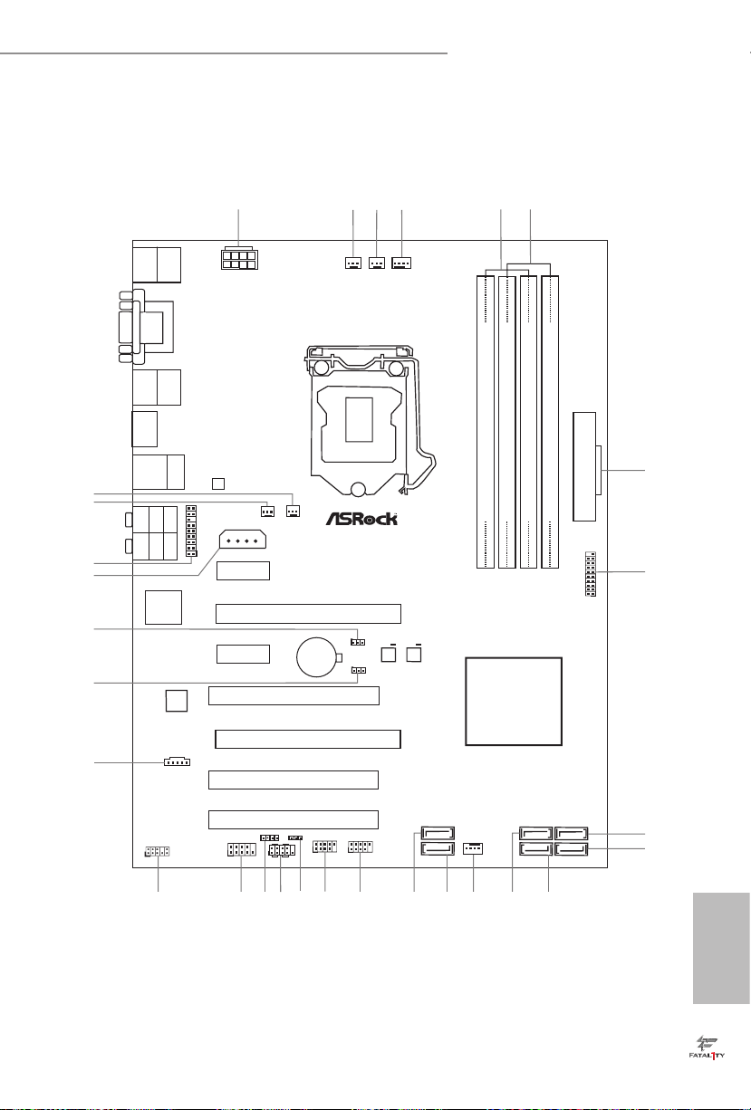
Motherboard Layout
Intel
H97
DDR 3_A2 (64 bit, 240- pin modu le)
DDR 3_A1 (64 bit, 240- pin modu le)
DDR 3_B2 (64 bit, 240- pin modu le)
DDR 3_B1 (64 bit, 240- pin modu le)
ATX12V1
Super
I/O
USB 2. 0
T: USB0
B: USB 1
Ps2
Keyb oard/
Mous e
ATXP WR 1
1
USB3_4 _5
LAN
PCIE2
Top:
RJ-45
USB 3 .0
T: USB2
B: US B3
Top:
Centra l/Bass
Center :
REAR SPK
Top:
LINE IN
Center :
FRONT
Bottom :
Optica l
SPDIF
Bottom :
MIC I N
PCIE4
PLED1
1
1
SPEAKER1
HDLED R ESET
PLED PWRBTN
PANEL1
1
USB6_7
1
USB4_5
1
COM1
1
1
HD_AUDI O1
H97 PER FOR MAN CE
SATA3_0
PCIE1
CHA_FAN1
CHA_FAN2
CHA_FAN3
PCI1
PCI2
RoH S
8
11
9
10
13
1516
17
19
21
14
12
24
2
3
5
7
6
1
29
22
USB 2. 0
T: USB2
B: USB 3
HDM I
FA TA L TY
1
Puri ty
Soun d 2
TM
VGA 1
DVI 1
SATA3_3
SATA3_1
SATA3_4
SATA3_2
SATA3_5
PCI3
PCIE3
USB 3. 0
T: USB0
B: USB 1
64Mb
BIOS
BIOS_B1
64Mb
BIOS
BIOS_A1
BIOS_B_LED 1
BIOS_SE L1
1
27
CPU_FAN1
CPU_FAN2PWR_FAN1
CMO S
Bat ter y
BIOS_A_LED 1
CLRMOS1
1
PCIE_ PWR1
1
TPMS1
4
1820
25
26
28
TB1
23
RoH S
PCI Ex p re ss 3.0
Fro nt USB 3.0
Fatal1ty H97 Performance Series
English
1
No. Description
1 ATX 12V Power Connector (ATX12V1)
2 Power Fan Connector (PWR_FAN1)
3 CPU Fan Connector (CPU_FAN2)
4 CPU Fan Connector (CPU_FAN1)
5 2 x 240-pin DDR3 DIMM Slots (DDR3_A1, DDR3_B1)
6 2 x 240-pin DDR3 DIMM Slots (DDR3_A2, DDR3_B2)
7 ATX Power Connector (ATXPWR1)
8 USB 3.0 Header (USB3_4_5)
9 SATA3 Connector (SATA3_2)
10 SATA3 Connector (SATA3_5)
11 SATA3 Connector (SATA3_4)
12 SATA3 Connector (SATA3_1)
13 Chassis Fan Connector (CHA_FAN1)
14 SATA3 Connector (SATA3_3)
15 SATA3 Connector (SATA3_0)
16 USB 2.0 Header (USB4_5)
17 USB 2.0 Header (USB6_7)
18 Power LED Header (PLED1)
19 System Panel Header (PANEL1)
20 Chassis Speaker Header (SPEAKER1)
21 COM Port Header (COM1)
22 Front Panel Audio Header (HD_AUDIO1)
23 underbolt AIC Connector (TB1)
24 BIOS Selection Jumper (BIOS_SEL1)
25 Clear CMOS Jumper (CLRCMOS1)
26 PCIe Power Connector (PCIE_PWR1)
27 TPM Header (TPMS1)
28 Chassis Fan Connector (CHA_FAN3)
29 Chassis Fan Connector (CHA_FAN2)
English
2
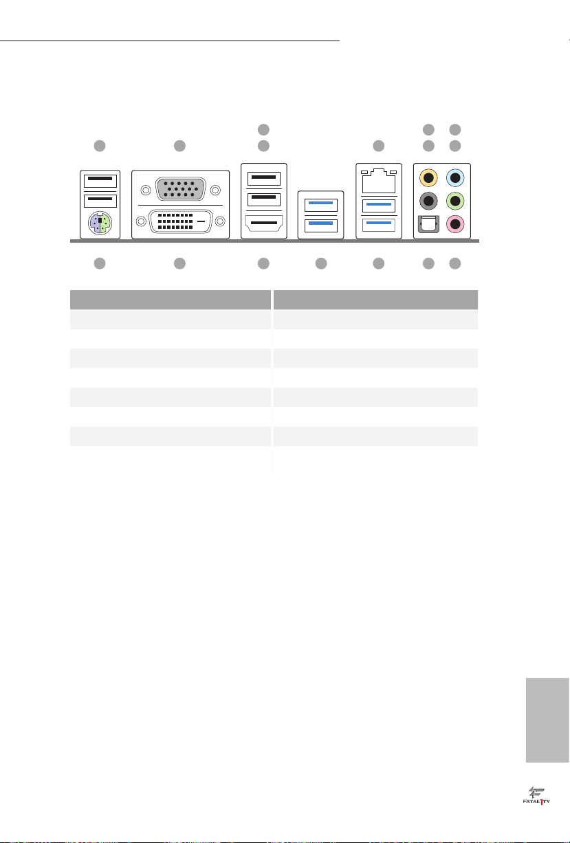
I/O Panel
Fatal1ty H97 Performance Series
3
1 2 4
No. Description No. Description
1 USB 2.0 Ports (USB01) 9 Front Speaker (Lime)**
2 D-Sub Port 10 Microphone (Pink)
3 Fatal1ty Mouse Port (USB2) 11 Optical SPDIF Out Port
4 USB 2.0 Port (USB3) 12 USB 3.0 Ports (USB3_23)
5 LAN RJ-45 Port* 13 USB 3.0 Ports (USB3_01)
6 Central / Bass (Orange) 14 HDMI Port
7 Rear Speaker (Black) 15 DVI-D Port
8 Line In (Light Blue) 16 PS/2 Mouse/Keyboard Port
5 7
698
101116 12131415
English
3

* ere are two LEDs on each LAN port. Please refer to the table below for the LAN port LED indications.
ACT/LINK L ED
SPEED LE D
LAN Por t
Activity / Link LED Speed LED
Status Description Status Description
O No Link O 10Mbps connection
Blinking Data Activity Orange 100Mbps connection
On Link Green 1Gbps connection
** If you use a 2- channel speaker, plea se connect the speake r’s plug into “Front Speaker Jack”. See the table below
for connection d etails in accordance w ith the type of speaker you use.
English
Audio Output
Channels
Front Speaker
(No. 9)
Rear Speaker
(No. 7)
Central / Bass
(No. 6)
2 V -- -- --
4 V V -- --
6 V V V --
8 V V V V
To enable Multi-Streaming, you need to connect a front panel audio cable to the front
panel audio header. Aer restarting your computer, you will nd the “Mixer” tool
on your system. Please select “Mixer ToolBox” , click “Enable playback multistreaming”, and click “ok”. Choose “2CH”, “4CH”, “6CH”, or “8CH” and then you are
allowed to select “Realtek HDA Pr imary output” to use the Rear Speaker, Central/
Bass, and Front Speake r, or select “Realtek HDA Audio 2nd output” to use the front
panel audio.
Line In
(No. 8)
4

Fatal1ty H97 Performance Series
Chapter 1 Introduction
ank you for purchasing ASRock Fatal1ty H97 Performance Series motherboard,
a reliable motherboard produced under ASRock ’s consistently stringent quality
control. It delivers excellent performance with robust design conforming to
ASRock’s commitment to quality and endurance.
Becau se the motherboard specications and the BIOS soware might be updated, the
content of this manual will be subject to change without notice. In ca se any modications of this manual occur, the updated version will be available on ASRock’s website
without further notice. If you require technical suppor t related to this motherboard,
please visit our website for spe cic information about the model you are using. You
may nd the l atest VGA cards and CPU support list on ASRock’s website a s well.
ASRock website http://www.asrock.com.
1.1 Package Contents
ASRock Fatal1ty H97 Performance Series Motherboard (ATX Form Factor)
•
ASRock Fatal1ty H97 Performance Series Quick Installation Guide
•
ASRock Fatal1ty H97 Performance Series Support CD
•
2 x Serial ATA (SATA) Data Cables (Optional)
•
1 x I/O Panel Shield
•
English
5

1.2 Specications
Platform
CPU
Chipset
Memory
Expansion
Slot
* If PCIE1 or PCIE3 slot is occupied, PCIE4 slot will run at x2
mode.
ATX Form Factor
•
High Density Glass Fabric PCB
•
Supports 5th Generation Intel® CoreTM i7/i5/i3/Pentium®/
•
Celeron® Processors (Socket 1150)
Supports New 4th and 4th Generation Intel® Xeon®/CoreTM i7/
•
i5/i3/Pentium®/Celeron® Processors (Socket 1150)
Digi Power design
•
8 Power Phase design
•
Supports Intel® Turbo Boost 2.0 Technology
•
Intel® H97
•
Dual Channel DDR3 Memory Technology
•
4 x DDR3 DIMM Slots
•
Supports DDR3 1600/1333/1066 non-ECC, un-buered
•
memory
Max. capacity of system memory: 32GB (see CAUTION)
•
Supports Intel® Extreme Memory Prole (XMP) 1.3 / 1.2
•
1 x PCI Express 3.0 x16 Slot (PCIE2: x16 mode)
•
1 x PCI Express 2.0 x16 Slot (PCIE4: x4 mode)
•
2 x PCI Express 2.0 x1 Slots
•
3 x PCI Slots
•
Supports AMD Quad CrossFireXTM and CrossFireXTM
•
English
6
Graphics
Intel® HD Graphics Built-in Visuals and the VGA outputs can
•
be supported only with processors which are GPU integrated.
Supports Intel® HD Graphics Built-in Visuals : Intel® Quick
•
Sync Video with AVC, MVC (S3D) and MPEG-2 Full
HW Encode1, Intel® InTruTM 3D, Intel® Clear Video HD
Technology, Intel® InsiderTM, Intel® HD Graphics 4400/4600
Pixel Shader 5.0, DirectX 11.1
•
Max. shared memory 1792MB
•
ree graphics output options: D-Sub, DVI-D and HDMI
•

Audio
Fatal1ty H97 Performance Series
Supports Triple Monitor
•
Supports HDMI with max. resolution up to 4K x 2K
•
(4096x2160) @ 24Hz
Supports DVI-D with max. resolution up to 1920x1200 @
•
60Hz
Supports D-Sub with max. resolution up to 1920x1200 @
•
60Hz
Supports Auto Lip Sync, Deep Color (12bpc), xvYCC and
•
HBR (High Bit Rate Audio) with HDMI Port (Compliant
HDMI monitor is required)
Supports HDCP with DVI-D and HDMI Ports
•
Supports Full HD 1080p Blu-ray (BD) playback with DVI-D
•
and HDMI Ports
7.1 CH HD Audio with Content Protection (Realtek ALC1150
•
Audio Codec)
Premium Blu-ray Audio support
•
Supports Surge Protection (ASRock Full Spike Protection)
•
Supports Purity SoundTM 2
•
- Nichicon Fine Gold Series Audio Caps
- 115dB SNR DAC with Dierential Amplier
- TI® NE5532 Premium Headset Amplier (Supports up to
600 Ohm headsets)
- Direct Drive Technology
- EMI Shielding Cover
- PCB Isolate Shielding
Supports DTS Connect
•
LAN
Gigabit LAN 10/100/1000 Mb/s
•
Giga PHY Intel® I218V
•
Supports Intel® Remote Wake Technology
•
Supports Wake-On-LAN
•
Supports Lightning/ESD Protection (ASRock Full Spike
•
Protection)
Supports Energy Ecient Ethernet 802.3az
•
Supports PXE
•
English
7

English
Rear Panel
I/O
Storage
Connector
1 x PS/2 Mouse/Keyboard Port
•
1 x D-Sub Port
•
1 x DVI-D Port
•
1 x HDMI Port
•
1 x Optical SPDIF Out Port
•
3 x USB 2.0 Ports (Supports ESD Protection (ASRock Full
•
Spike Protection))
1 x Fatal1ty Mouse Port (USB 2.0) (Supports ESD Protection
•
(ASRock Full Spike Protection))
4 x USB 3.0 Ports (Supports ESD Protection (ASRock Full
•
Spike Protection))
1 x RJ-45 LAN Port with LED (ACT/LINK LED and SPEED
•
LED)
HD Audio Jacks: Rear Speaker / Central / Bass / Line in /
•
Front Speaker / Microphone
6 x SATA3 6.0 Gb/s Connectors, support RAID (RAID 0,
•
RAID 1, RAID 5, RAID 10, Intel Rapid Storage Technology
13 and Intel Smart Response Technology), NCQ, AHCI and
Hot Plug
1 x COM Port Header
•
1 x TPM Header
•
1 x Power LED Header
•
2 x CPU Fan Connectors (1 x 4-pin, 1 x 3-pin)
•
3 x Chassis Fan Connectors (1 x 4-pin, 2 x 3-pin)
•
1 x Power Fan Connector (3-pin)
•
1 x 24 pin ATX Power Connector
•
1 x 8 pin 12V Power Connector (Hi-Density Power
•
Connector)
1 x PCIe Power Connector
•
1 x Front Panel Audio Connector
•
1 x underbolt AIC Connector
•
2 x USB 2.0 Headers (Support 4 USB 2.0 ports) (Supports ESD
•
Protection (ASRock Full Spike Protection))
1 x USB 3.0 Header (Supports 2 USB 3.0 ports) (Supports ESD
•
Protection (ASRock Full Spike Protection))
8

BIOS
Feature
Hardware
Monitor
OS
Certications
Fatal1ty H97 Performance Series
2 x 64Mb AMI UEFI Legal BIOS with multilingual GUI sup-
•
port (1 x Main BIOS and 1 x Backup BIOS)
Supports Secure Backup UEFI Technology
•
ACPI 1.1 Compliant wake up events
•
SMBIOS 2.3.1 Support
•
CPU, DRAM, PCH 1.05V, PCH 1.5V Voltage Multi-adjust-
•
ment
CPU/Chassis temperature sensing
•
CPU/Chassis/Power Fan Tachometer
•
CPU/Chassis Quiet Fan (Auto adjust chassis fan speed by
•
CPU temperature)
CPU/Chassis Fan multi-speed control
•
Voltage monitoring: +12V, +5V, +3.3V, CPU Vcore
•
Microso® Windows® 8.1 32-bit / 8.1 64-bit / 8 32-bit / 8 64-
•
bit / 7 32-bit / 7 64-bit
FCC, CE, WHQL
•
ErP/EuP ready (ErP/EuP ready power supply is required)
•
* For detailed product information, please visit our website: http://www.asrock.com
Please realize that the re is a certain risk involved with overclocking, including adjusting the setting in the BIOS, applying Untied Ove rclocking Technology, or using thirdparty overclocking tools. Overclocking may aect your system’s stability, or even cause
damage to the components and devices of your system. It should be done at your own
risk and expense. We are not responsible for possible damage cau sed by overclocking.
Due to limitation, the actual memory size may be less than 4GB for the reservation
for system usage under Windows® 32-bit operating systems. Windows® 64-bit operating systems do not have such limitations. You can use ASRock XFast RAM to utilize
the memory that Windows® cannot use.
English
9

Chapter 2 Installation
is is an ATX form factor motherboard. Before you install the motherboard, study
the conguration of your chassis to ensure that the motherboard ts into it.
Pre-installation Precautions
Take note of the following precautions before you install motherboard components
or change any motherboard settings.
Make sure to unplug the power cord before installing or removing the motherboard
•
components. Failure to do so may cause physical injuries and damages to motherboard
components.
In order to avoid damage from static electricity to the motherboard’s components,
•
NEVER place your motherboard directly on a carpet. Also remember to use a grounded
wrist strap or touch a safety grounded object before you handle the components.
Hold components by the edges and do not touch the ICs.
•
Whenever you uninstall any components, place them on a grounded anti-static pad or
•
in the bag that comes with the components.
When placing screws to secure the motherboard to the chassis, please do not over-
•
tighten the screws! Doing so may damage the motherboard.
English
10
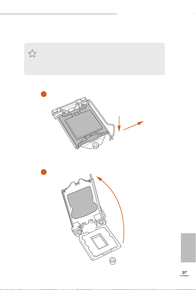
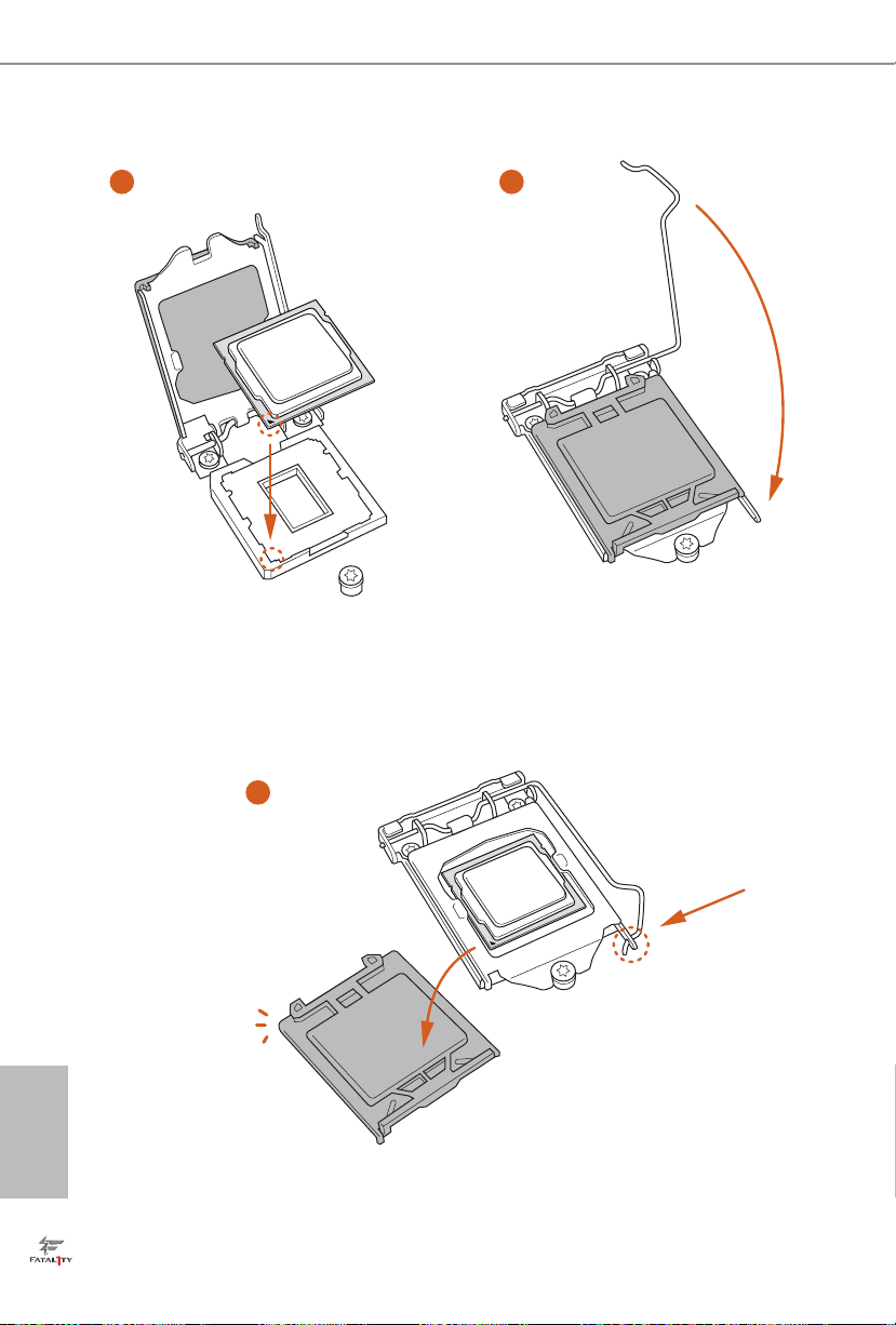
2.1 Installing the CPU
1. Before you inser t the 1150-Pin CPU into the socket, please check if the PnP cap is on
the socket, if the CPU surfa ce is unclean, or if there are any bent pins in the socket.
Do not force to insert the CPU into the socket if above situation is found. Otherwise,
the CPU will be seriously damaged .
2. Unplug all power cables before installing the CPU.
1
Fatal1ty H97 Performance Series
A
B
2
English
11
3
5
4
English
12

Fatal1ty H97 Performance Series
Please save and replace the cover if the processor i s removed. e cover must be placed
if you wish to retur n the motherboard for aer service.
13
English
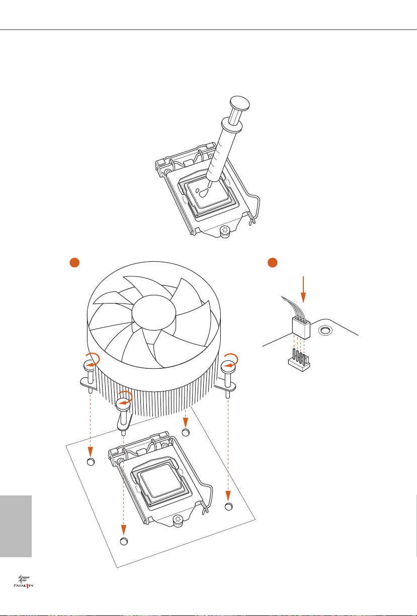
2.2 Installing the CPU Fan and Heatsink
1 2
English
14
N
FA
_
U
P
C
Fatal1ty H97 Performance Series
2.3 Installing Memory Modules (DIMM)
is motherboard provides four 240-pin DDR3 (Double Data Rate 3) DIMM slots,
and supports Dual Channel Memory Technology.
1. For dual channel conguration, you always need to install identical (the same
brand, speed , size and chip-type) DDR3 DIMM pairs.
2. It is unable to activate Dual Channel Memory Technology with only one or three
memory module installed.
3. It is not allowed to install a DDR or DDR 2 memory module into a DDR3 slot;
otherwise, this motherboard and DIMM may be damaged.
Dual Channel Memory Conguration
Priority DDR3_A1 DDR3_A2 DDR3_B1 DDR3_B2
1 Populated Populated
2 Populated Populated
3 Populated Populated Populated Populated
e DIMM only ts in one correct orientation. It will cause permanent damage to
the mothe rboard and the DIMM if you force the DIMM into the slot at incor rect
orientation.
English
15

1
2
English
16
3
Fatal1ty H97 Performance Series
2.4 Expansion Slots (PCI and PCI Express Slots)
ere are 3 PCI slots and 4 PCI Express slots on the motherboard.
Before installing an ex pansion card, please make sure that the power supply is
switched o or the power cord is unplugged. Plea se read the documentation of the
expan sion card and make necessary hardware settings for the card before you start
the installation.
PCI slots:
e PCI1, PCI2 and PCI3 slots are used to install expansion cards that have 32-bit
PCI interface.
PCIe slots:
PCIE1 (PCIe 2.0 x1 slot) is used for PCI Express x1 lane width cards.
PCIE2 (PCIe 3.0 x16 slot) is used for PCI Express x16 lane width graphics cards.
PCIE3 (PCIe 2.0 x1 slot) is used for PCI Express x1 lane width cards.
PCIE4 (PCIe 2.0 x16 slot) is used for PCI Express x4 lane width graphics cards.
PCIe Slot Congurations
PCIE2 PCIE4
Single Graphics Card x16 N/A
Two Graphics Cards in
CrossFireXTM Mode
For a better ther mal environment, please connect a chassi s fan to the motherboard’s
chassis fan connector (CHA_ FAN1, CHA_ FAN2 or CHA_ FAN3) when using multiple graphics cards.
x16 x4
English
17
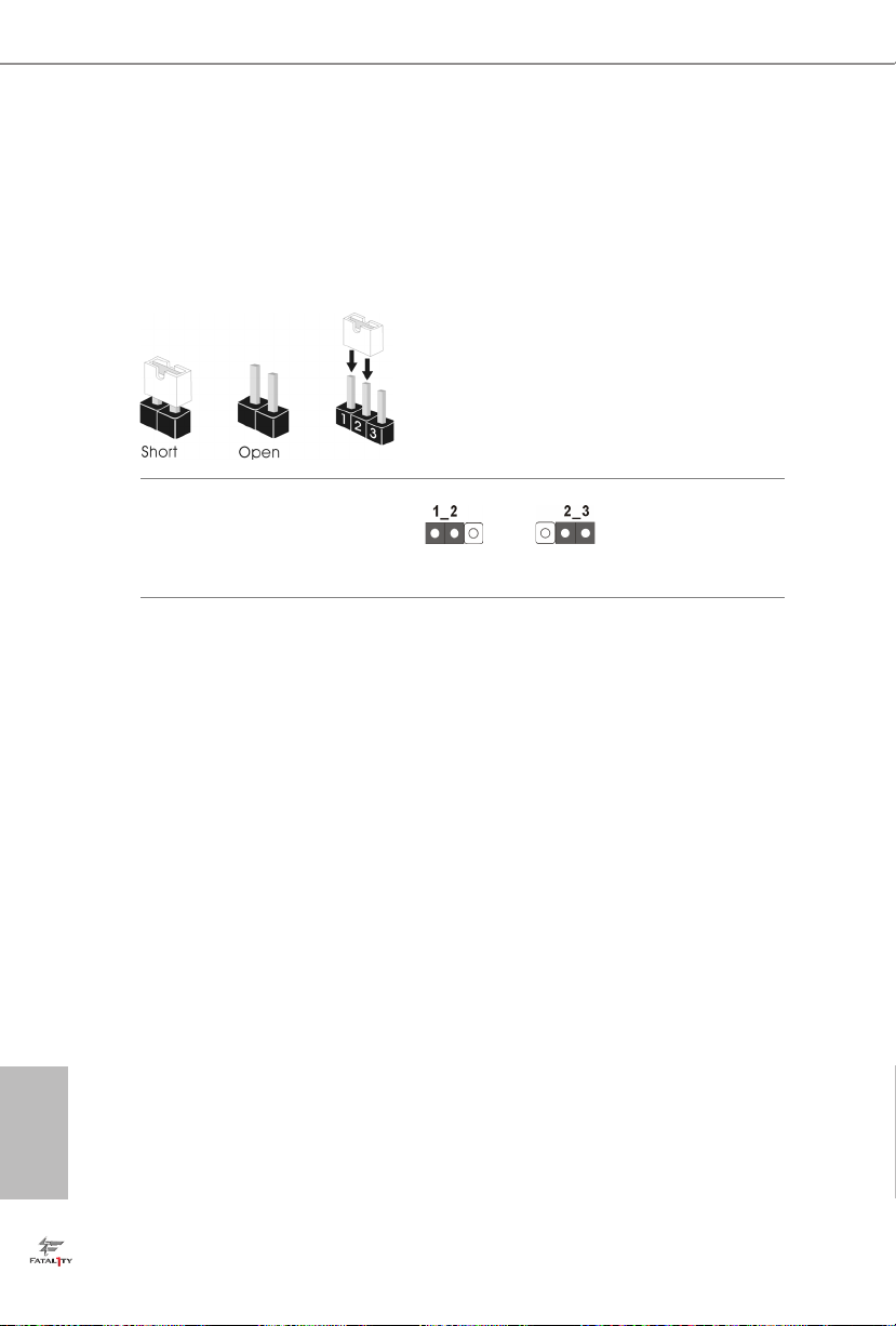
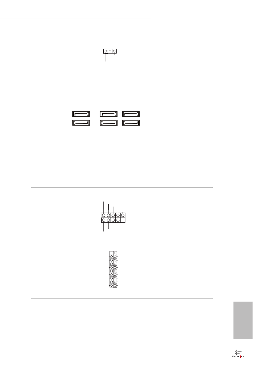
2.5 Jumpers Setup
e illustration shows how jumpers are setup. When the jumper cap is placed on
the pins, the jumper is “Short”. If no jumper cap is placed on the pins, the jumper
is “Open”. e illustration shows a 3-pin jumper whose pin1 and pin2 are “Short”
when a jumper cap is placed on these 2 pins.
Clear CMOS Jumper
(CLRCMOS1)
(see p.1, No. 25)
CLRCMOS1 allows you to clear the data in CMOS. To clear and reset the system
parameters to default setup, please turn o the computer and unplug the power
cord from the power supply. Aer waiting for 15 seconds, use a jumper cap to
short pin2 and pin3 on CLRCMOS1 for 5 seconds. However, please do not clear
the CMOS right aer you update the BIOS. If you need to clear the CMOS when
you just nish updating the BIOS, you must boot up the system rst, and then shut
it down before you do the clear-CMOS action. Please be noted that the password,
date, time, and user default prole will be cleared only if the CMOS battery is
removed.
Clear CMOSDefault
English
18
Fatal1ty H97 Performance Series
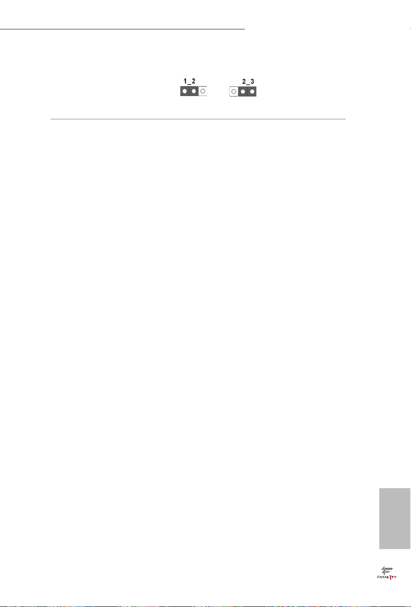
BIOS Selection Jumper
(BIOS_SEL1)
(see p.1, No. 24)
is motherboard has two BIOS onboard, a main BIOS (BIOS_A) and a backup
BIOS (BIOS_B), which enhances protection for the safety and stability of your
system. Normally, the system works on the main BIOS. However, if the main BIOS
is corrupted or damaged, please use a jumper cap to short pin2 and pin3, then
the backup BIOS will take over on the next system boot. Aer that, use “Secure
Backup UEFI“ in BIOS setup utility to copy the BIOS le to the main BIOS to
ensure normal system operation. For the sake of system safety, users cannot
update the backup BIOS manually. Users may refer to the BIOS LED (BIOS_A_
LED or BIOS_B_LED) to identify which BIOS is activated currently.
Default
(Main BIOS)
Backup BIOS
19
English
2.6 Onboard Headers and Connectors
Onboard headers and connectors are NOT jumpers. Do NOT place jumper caps over
these headers and connectors. Placing jumper caps over the headers and connectors
will cause permanent damage to the motherboard.
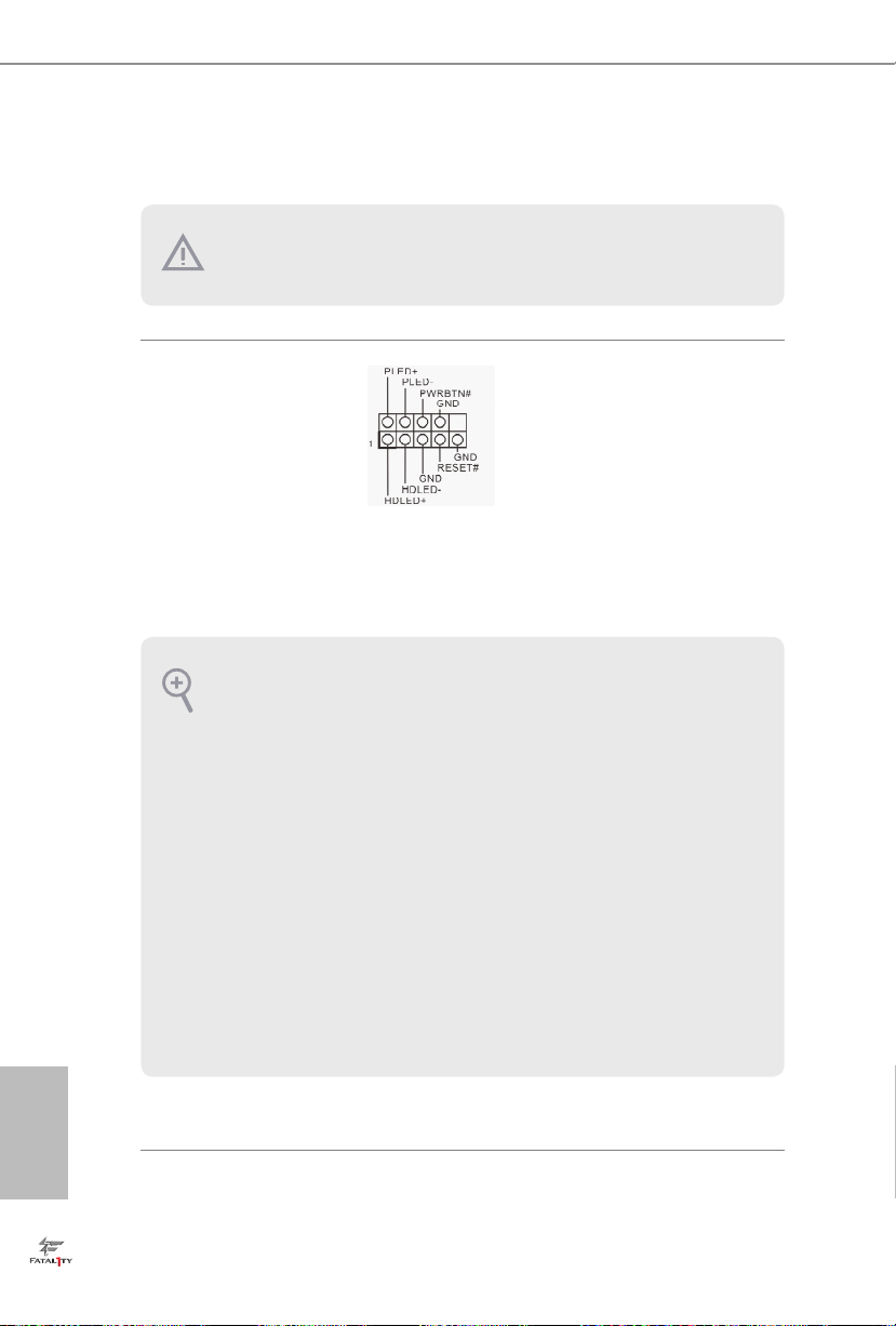
System Panel Header
(9-pin PANEL1)
(see p.1, No. 19)
PWRBTN (Power Switch):
Connec t to the power switch on the chassi s front panel. You may congure the way to
turn o your system using the power switch.
RESET (Reset Switch):
Connec t to the reset switch on the chassis front panel. Press the reset sw itch to restart
the computer if the compute r freezes and fails to perform a normal restart.
PLED (Syste m Power LED):
Connec t to the power status indicator on the chassis front panel. e LED i s on when
the system is ope rating. e LED keeps blinking when the system i s in S1/S3 sleep state.
e LED is o when the system is in S4 sleep state or powered o (S5).
HDLED (Ha rd Drive Activity LED):
Connec t to the hard drive activity LED on the chassis front panel. e LED is on when
the hard dr ive is reading or writing data.
e front panel design may dier by chassis. A front panel module mainly consists
of power switch, reset switch, power LED, hard dr ive activity LED, speak er and etc.
When connecting your chassis front panel module to this head er, make sure the wire
assig nments and the pin assig nments are matched correctly.
Connect the power
switch, reset switch and
system status indicator on
the chassis to this header
according to the pin
assignments below. Note
the positive and negative
pins before connecting
the cables.
English
20
Fatal1ty H97 Performance Series
Power LED Header
(3-pin PLED1)
(see p.1, No. 18)
Serial ATA3 Connectors
(SATA3_0:
see p.1, No. 15)
(SATA3_1:
see p.1, No. 12)
(SATA3_2:
see p.1, No. 9)
(SATA3_3:
see p.1, No. 14)
(SATA3_4:
see p.1, No. 11)
(SATA3_5:
see p.1, No. 10)
USB 2.0 Headers
(9-pin USB4_5)
(see p.1, No. 16)
(9-pin USB6_7)
(see p.1, No. 17)
1
USB _PW R
1
USB _PW R
PLE D+
PLE D+
P-
P+
P+
P-
PLE D-
GND
GND
SATA3_2SATA3_0 SATA3_1
SATA3_5SATA3_3 SATA3_4
DUM MY
Please connect the chassis
power LED to this header
to
indicate the system’s
power status.
ese six SATA3
connectors support SATA
data cables for internal
storage devices with up to
6.0 Gb/s data transfer rate.
Besides four USB 2.0 ports
on the I/O panel, there
are two headers on this
motherboard. Each USB
2.0 header can support
two ports.
USB 3.0 Headers
(19-pin USB3_4_5)
(see p.1, No. 8)
Vbus
IntA _PA_S SRX-
IntA _PA_S SRX+
GND
IntA _PA_S STX-
IntA _PA_S STX+
GND
IntA _PA_D -
IntA _PA_D +
VbusVbus
IntA _PB_ SSRX -
IntA _PB_ SSRX +
GND
IntA _PB_ SSTX -
IntA _PB_ SSTX +
GND
IntA _PB_ D-
IntA _PB_ D+
Dumm y
1
Besides four USB 3.0
ports on the I/O panel,
there is one header on this
motherboard. Each USB
3.0 header can support
two ports.
English
21
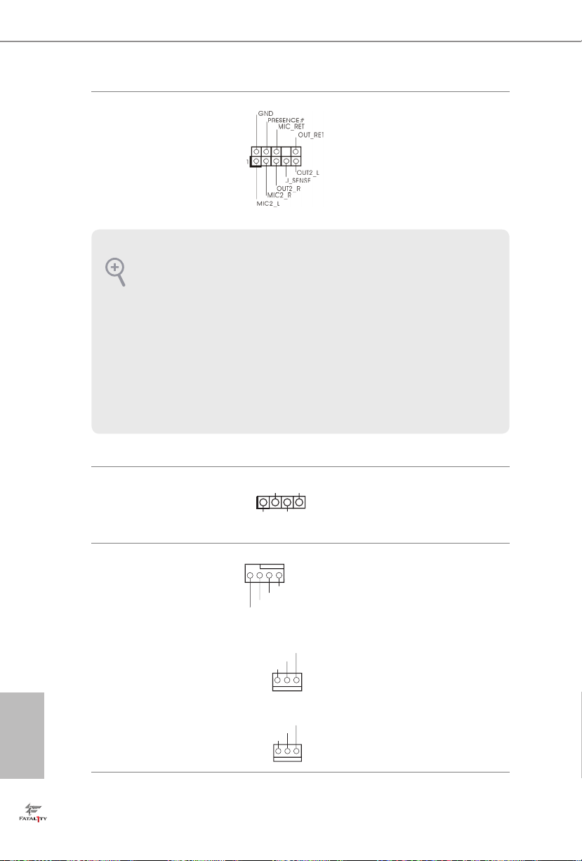
Front Panel Audio Header
GND
FAN_ VOLTAG E
FAN_ SPEE D
GND
+12 V
FAN_ SPE ED
(9-pin HD_AUDIO1)
(see p.1, No. 22)
1. High Denition Audio supports Jack Sensing, but the panel wire on the chassis must
suppor t HDA to function correctly. Please follow the instructions in our manual and
chassis manual to install your system.
2. If you use an AC’97 audio panel, please install it to the f ront panel audio header by
the steps below:
A. Connect Mic_IN (MIC) to MIC2_ L.
B. Conne ct Audio_R (RIN) to OUT2_R and Audio_ L (LIN) to OUT2_ L.
C. Connect Ground (GND) to Ground (GND).
D. MIC_ RET and OUT_RET are for the HD audio panel only. You don’t need to
connect them for the AC’97 audio panel.
E. To activate the front mic, go to the “FrontMic” Tab in the Realtek Control panel
and adju st “Recording Volume”.
Chassis Speaker Header
(4-pin SPEAKER1)
(see p.1, No. 20)
DUM MY
1
+5V
SPE AKE R
DUM MY
is header is for
connecting audio devices
to the front audio panel.
Please connect the chassis
speaker to this header.
English
22
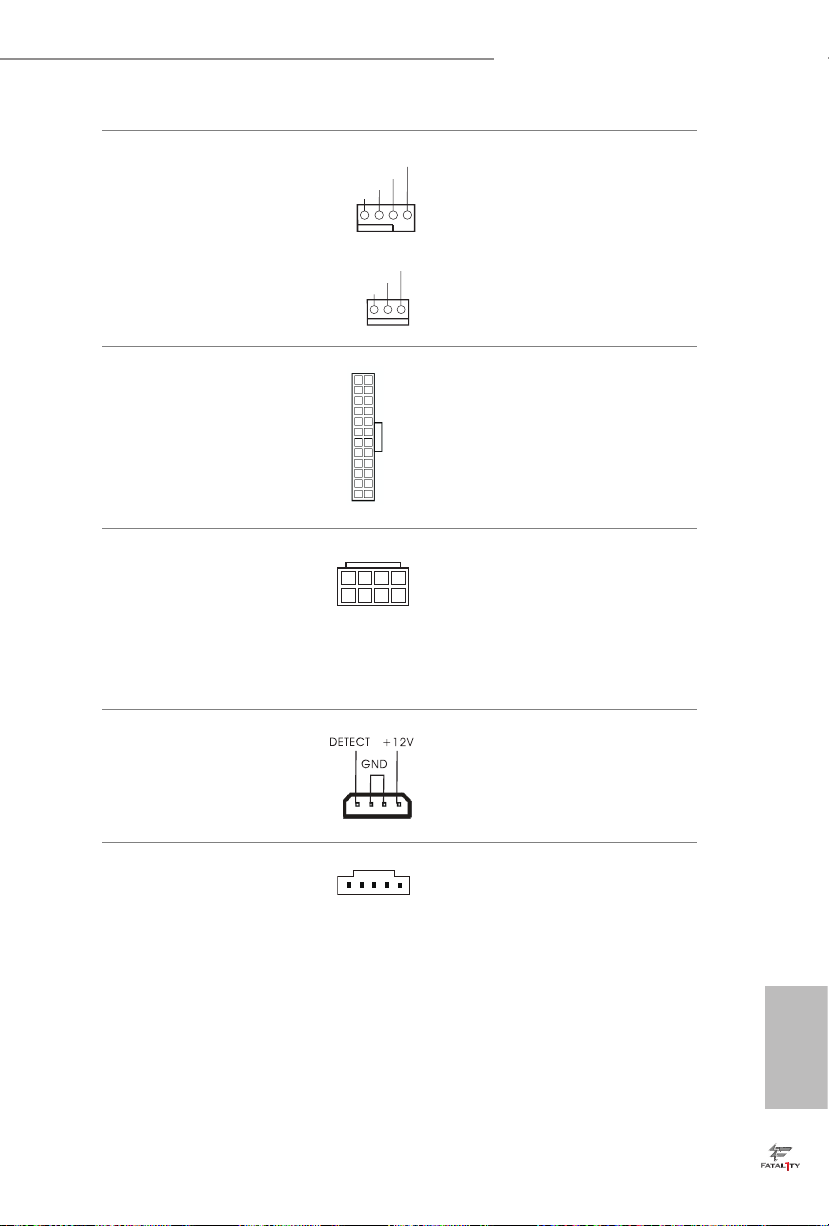
Chassis and Power Fan
Connectors
(4-pin CHA_FAN1)
(see p.1, No. 13)
(3-pin CHA_FAN2)
(see p.1, No. 29)
(3-pin CHA_FAN3)
(see p.1, No. 28)
(3-pin PWR_FAN1)
(see p.1, No. 2)
GND
+12V
FAN_S PEE D
FAN_S PEE D_C ONTR OL
Please connect fan cables
to the fan connectors and
match the black wire to
the ground pin.
Fatal1ty H97 Performance Series
FAN_ SPEE D
FAN_ SPEE D_C ONT ROL
GND
+12 V
1 2 3 4
GND
FAN_ VOLTAG E
FAN_ SPEE D
CPU Fan Connectors
(4-pin CPU_FAN1)
(see p.1, No. 4)
(3-pin CPU_FAN2)
(see p.1, No. 3)
ATX Power Connector
(24-pin ATXPWR1)
(see p.1, No. 7)
ATX 12V Power
Connector
(8-pin ATX12V1)
(see p.1, No. 1)
PCIe Power Connector
(4-pin PCIE_PWR1)
(see p.1, No. 26)
12
24
1
13
8 5
4 1
is motherboard provides a 4-Pin CPU fan
(Quiet Fan) connector.
If you plan to connect a
3-Pin CPU fan, please
connect it to Pin 1-3.
is motherboard provides a 24-pin ATX power
connector. To use a 20-pin
ATX power supply, please
plug it along Pin 1 and Pin
13.
is motherboard provides an 8-pin ATX 12V
power connector. To use a
4-pin ATX power supply,
please plug it along Pin 1
and Pin 5.
Please connect a 4 pin molex
power cable to this connector
when more than three
graphics cards are installed.
underbolt AIC
Connector
(5-pin TB1)
(see p.1, No. 23)
Please connect a 5-pin signal
cable (GPIO cable) to this
connector when you install
a underboltTM add-in card
(AIC).
English
23
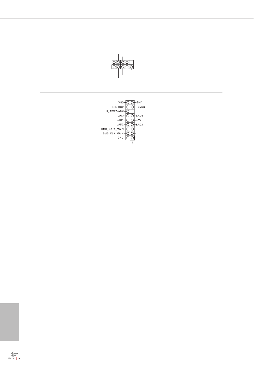
Serial Port Header
(9-pin COM1)
(see p.1, No. 21)
1
RRXD 1
DDTR #1
TTXD 1
DDCD #1
DDSR #1
CCTS #1
RRTS #1
GND
is COM1 header
supports a serial port
module.
RRI# 1
TPM Header
(17-pin TPMS1)
(see p.1, No. 27)
is connector supports
Trusted Platform Module
(TPM) system, which can
securely store keys, digital
PCI RST#
certicates, passwords,
FRA ME
PCI CLK
and data. A TPM system
also helps enhance
network security, protects
digital identities, and
ensures platform integrity.
English
24

Fatal1ty H97 Performance-Serie
1 Einleitung
Vielen Dank, dass Sie sich für die Fatal1ty H97 Performance-Serie von ASRock
entschieden haben – ein zuverlässiges Motherboard, das konsequent unter der
strengen Qualitätskontrolle von ASRock hergestellt wurde. Es liefert ausgezeichnete
Leistung mit robustem Design, das ASRocks Streben nach Qualität und Beständigkeit
erfüllt.
Da die technischen Daten des Motherboards sowie die BIOS-Soware aktualisiert werden
können, kann der Inhalt dieser Anleitung ohne Ankündigung geändert werden. Falls diese
Anleitung irgendwelchen Änderungen unterliegt, wird die aktualisierte Version ohne weitere Hinweise auf der ASRock-Webseite zur Verfügung gestellt. Sollten Sie technische Hilfe
in Bezug auf dieses Motherboard benötigen, erhalten Sie auf unserer Webseite spezischen
Informationen über das von Ihnen verwendete Modell. Auch nden Sie eine aktuelle Liste
unterstützter VGA-Karten und Prozessoren auf der ASRock-Webseite: ASRock-Website
http://www.asrock.com.
1.1 Lieferumfang
• ASRock Fatal1ty H97 Performance-Serie – Motherboard (ATX-Formfaktor)
• ASRock Fatal1ty H97 Performance-Serie – Schnellinstallationsanleitung
• ASRock Fatal1ty H97 Performance-Serie – Support-CD
• 2 x Serial-ATA- (SATA) Datenkabel (optional)
• 1 x E/A-Blendenabschirmung
25
Deutsch

1.2 Technische Daten
Plattform
Prozessor
Chipsatz
Speicher
Erweiterungssteckplatz
• ATX-Formfaktor
• Leiterplatte mit hochdichtem Glasgewebe
• Unterstützt Intel® CoreTM i7/i5/i3/Pentium®/Celeron®-
Prozessoren (Sockel 1150) der 5. Generation
• Unterstützt Intel® Xeon®/CoreTM i7/i5/i3/Pentium®/Celeron®-
Prozessoren (Sockel 1150) der 4. und neuen 4. Generation
• Digipower-Design
• 8-Leistungsphasendesign
• Unterstützt Intel® Turbo Boost 2.0-Technologie
• Intel® H97
• Dualkanal-DDR3-Speichertechnologie
• 4 x DDR3-DIMM-Steckplätze
• Unterstützt DDR3 1600/1333/1066 non-ECC, ungepuerter
Speicher
• Systemspeicher, max. Kapazität: 32 GB (siehe ACHTUNG)
• Unterstützt Intel® Extreme Memory Prole (XMP)1.3/1.2
• 1 x PCI-Express 3.0-x16-Steckplatz (PCIE2:x16-Modus)
• 1 x PCI-Express 2.0-x16-Steckplatz (PCIE4:x4-Modus)
* Wenn der PCIE1- oder PCIE3-Steckplatz belegt ist, läu der
PCIE4-Steckplatz im x2-Modus.
• 2 x PCI-Express 2.0-x1-Steckplätze
• 3 x PCI-Steckplätze
• Unterstützt AMD Quad CrossFireXTM und CrossFireXTM
Deutsch
26
Grakkarte
• Integrierte Intel® HD Graphics-Visualisierung und VGAAusgänge können nur mit Prozessoren unterstützt werden,
die GPU-integriert sind.
• Unterstützt integrierte Intel® HD Graphics-Visualisierung:
Intel® Quick Sync Video mit AVC, MVC (S3D) und MPEG-2
Full HW Encode1, Intel® InTruTM 3D, Intel® Clear Video HD
Technology, Intel® InsiderTM, Intel® HD Graphics 4400/4600
• Pixel Shader 5.0, DirectX 11.1
• Max. geteilter Speicher: 1792 MB
• Drei Grakkarten-Ausgangsoptionen: D-Sub, DVI-D und
HDMI
 Loading...