


Version 1.0
Published December 2013
Copyright©2013 ASRock INC. All rights reserved.
Copyright Notice:
No part of this documentation may be reproduced, transcribed, transmitted, or
translated in any language, in any form or by any means, except duplication of
documentation by the purchaser for backup purpose, without written consent of
ASRock Inc.
Products and corporate names appearing in this documentation may or may not
be registered trademarks or copyrights of their respective companies, and are used
only for identication or explanation and to the owners’ benet, without intent to
infringe.
Disclaimer:
Specications and information contained in this documentation are furnished for
informational use only and subject to change without notice, and should not be
constructed as a commitment by ASRock. ASRock assumes no responsibility for
any errors or omissions that may appear in this documentation.
With respect to the contents of this documentation, ASRock does not provide
warranty of any kind, either expressed or implied, including but not limited to
the implied warranties or conditions of merchantability or tness for a particular
purpose.
In no event shall ASRock, its directors, ocers, employees, or agents be liable for
any indirect, special, incidental, or consequential damages (including damages for
loss of prots, loss of business, loss of data, interruption of business and the like),
even if ASRock has been advised of the possibility of such damages arising from any
defect or error in the documentation or product.
is device complies with Part 15 of the FCC Rules. Operation is subject to the following
two conditions:
(1) this device may not cause harmful interference, and
(2) this device must accept any interference received, including interference that
may cause undesired operation.
CALIFORNIA, USA ONLY
e Lithium batter y adopted on this motherboard contains Perchlorate, a toxic substance
controlled in Perchlorate Best Management Practices (BMP) regulations passed by the
California Legislature. When you discard the Lithium battery in California, USA, please
follow the related regulations in advance.
“Perchlorate Material-special handling may apply, see www.dtsc.ca.gov/hazardouswaste/
perchlorate”
ASRock Website: http://www.asrock.com

e terms HDMI™ and HDMI High-Denition Multimedia Interface, and the HDMI
logo are trademarks or registered trademarks of HDMI Licensing LLC in the United
States and other countries.
Manufactured under license under U.S. Patent Nos: 5,956,674; 5,974,380; 6,487,535;
7,003,467 & other U.S. and worldwide patents issued & pending. DTS, the Symbol, &
DTS and the Symbol together is a registered trademark & DTS Connect, DTS Interactive,
DTS Neo:PC are trademarks of DTS, Inc. Product includes soware.
© DTS, Inc., All Rights Reserved.

Fatal1ty Story
Who knew that at age 19, I would be a World Champion PC gamer. When I was 13, I actually
played competitive billiards in professional tournaments and won four or ve games o guys
who played at the highest level. I actually thought of making a career of it, but at that young
age situations change rapidly. Because I’ve been blessed with great hand-eye coordination and
a grasp of mathematics (an important element in video gaming) I gravitated to that activity.
GOING PRO
I started professional gaming in 1999 when I entered the CPL (Cyberathlete Professional
League) tournament in Dallas and won $4,000 for coming in third place. Emerging as one
of the top players in the United States, a company interested in sponsoring me ew me to
Sweden to compete against the top 12 players in the world. I won 18 straight games, lost
none, and took rst place, becoming the number one ranked Quake III player in the world
in the process. Two months later I followed that success by traveling to Dallas and defending
my title as the world’s best Quake III player, winning the $40,000 grand prize. From there
I entered competitions all over the world, including Singapore, Korea, Germany, Australia,
Holland and Brazil in addition to Los Angeles, New York and St. Louis.
WINNING STREAK
I was excited to showcase my true gaming skills when defending my title as CPL
Champion of the year at the CPL Winter 2001 because I would be competing in a totally
dierent rst person shooter (fps) game, Alien vs. Predator II. I won that competition and
walked away with a new car. e next year I won the same title playing Unreal Tournament
2003, becoming the only three-time CPL champion of the year. And I did it playing a
different game each year, something no one else has ever done and a feat of which I am
extremely proud.
At QuakeCon 2002, I faced o against my rival ZeRo4 in one of the most highly
anticipated matches of the year, winning in a 14 to (-1) killer victory. Competing at Quakecon
2004, I became the World’s 1st Doom3 Champion by defeating Daler in a series of very
challenging matches and earning $25,000 for the victory.
Since then Fatal1ty has traveled the globe to compete against the best in the world, winning
prizes and acclaim, including the 2005 CPL World Tour Championship in New York City for
a $150,000 rst place triumph. In August 2007, Johnathan was awarded the rst ever Lifetime
Achievement Award in the four year history of the eSports-Award for “showing exceptional
sportsmanship, taking part in shaping eSports into what it is today and for being the prime
representative of this young sport. He has become the gurehead for eSports worldwide”.

LIVIN’ LARGE
Since my rst big tournament wins, I have been a “Professional Cyberathlete”, traveling the
world and livin’ large with lots of International media coverage on outlets such as MTV,
ESPN and a 60 Minutes segment on CBS to name only a few. It's unreal - it's crazy. I’m living
a dream by playing video games for a living. I’ve always been athletic and took sports like
hockey and football very seriously, working out and training hard. is discipline helps me
become a better gamer and my drive to be the best has opened the doors necessary to become
a professional.
A DREAM
Now, another dream is being realized – building the ultimate gaming computer, made
up of the best parts under my own brand. Quality hardware makes a huge difference in
competitions…a couple more frames per second and everything gets really nice. It’s all about
getting the computer processing faster and allowing more uid movement around the maps.
My vision for Fatal1ty hardware is to allow gamers to focus on the game without worrying
about their equipment, something I’ve preached since I began competing. I don’t want to
worry about my equipment. I want to be there – over and done with - so I can focus on
the game. I want it to be the fastest and most stable computer equipment on the face of the
planet, so quality is what Fatal1ty Brand products represent.
Johnathan “Fatal1ty” Wendel
e Fatal1ty name, Fatal1ty logos and the Fatal1ty likeness are registered trademarks of Fatal1ty, Inc., and are used
under license. © 2013 Fatal1ty, Inc. All rights reserved. All other trademarks are the property of their respective
owners.

Contents
1. Introduction 1
1.1 Package Contents 1
1.2 Specications 2
1.3 Unique Features 7
1.4 Motherboard Layout 11
1.5 I/O Panel 13
2. Installation 15
2.1 CPU Installation 16
2.2 Installation of CPU Fan and Heatsink 17
2.3 Installation of Memory Modules (DIMM) 18
2.4 Expansion Slots (PCI and PCI Express Slots) 20
2.5 Jumpers Setup 21
2.6 Onboard Headers and Connectors 22
2.7 CrossFireX
TM
and Quad CrossFireXTM Operation Guide 27
2.8 AMD Dual Graphics Operation Guide 30
3. Software and Utilities Operation 32
3.1 Installing Drivers 32
3.2 F-Stream 33
3.3 Killer Network Manager 37
3.4 Start8 40

4. UEFI SETUP UTILITY 47
4.1 Introduction 47
4.1.1 UEFI Menu Bar 47
4.1.2 Navigation Keys 48
4.2 Main Screen 48
4.3 OC Tweaker Screen 49
4.4 Advanced Screen 52
4.4.1 CPU Conguration 53
4.4.2 North Bridge Conguration 54
4.4.3 South Bridge Conguration 55
4.4.4 Storage Conguration 56
4.4.5 Super IO Conguration 57
4.4.6 ACPI Conguration 58
4.4.7 USB Conguration 60
4.4.8 Trusted Computing 61
4.5 Tool 62
4.6 Hardware Health Event Monitoring Screen 65
4.7 Boot Screen 66
4.8 Security Screen 68
4.9 Exit Screen 69

Fatal1ty FM2A88X+ Killer Series
1. Introduction
Thank you for purchasing ASRock Fatal1ty FM2A88X+ Killer Series motherboard,
a reliable motherboard produced under ASRock’s consistently stringent quality control. It delivers excellent performance with robust design conforming to ASRock’s
commitment to quality and endurance.
In this documentation, Chapter 1 and 2 contains the introduction of the motherboard
and step-by-step installation guides. Chapter 3 contains the operation guide of the
software and utilities. Chapter 4 contains the conguration guide of the BIOS setup.
Because the motherboard specications and the BIOS software might
be updated, the content of this manual will be subject to change without
notice. In case any modications of this manual occur, the updated version will be available on ASRock website without further notice. You may
nd the latest VGA cards and CPU support lists on ASRock website as
well. ASRock website http://www.asrock.com
If you require technical support related to this motherboard, please visit
our website for specic information about the model you are using.
www.asrock.com/support/index.asp
1.1 Package Contents
ASRock Fatal1ty FM2A88X+ Killer Series Motherboard (ATX Form Factor)
ASRock Fatal1ty FM2A88X+ Killer Series Quick Installation Guide
ASRock Fatal1ty FM2A88X+ Killer Series Support CD
2 x Serial ATA (SATA) Data Cables (Optional)
1 x I/O Panel Shield
ASRock Reminds You...
To get better performance in Windows® 8 / 8 64-bit / 7 / 7 64-bit, it is
recommended to set the BIOS option in Storage Conguration to AHCI
mode.
English
1

1.2 Specications
English
Platform
A-Style
Gaming
Armor
CPU
Chipset
Memory
• ATX Form Factor
• Premium Gold Capacitor design (100% Japan made
high quality conductive polymer capacitors)
• Purity Sound
CPU Power
• Hi-Density Power Connector
VGA Card
• 15μGold Finger in VGA PCIe Slot (PCIE2)
• SLI/CrossFireX Power Connector
Internet
• Qualcomm® Atheros® KillerTM LAN
Audio
• Purity Sound
• Supports Socket FM2+ 95W / FM2 100W processors
• Digi Power design
• 4 + 2 Power Phase design
• AMD A88X (Bolton-D4)
• Dual Channel DDR3 Memory Technology
• 4 x DDR3 DIMM Slots
• Supports DDR3 2600+(OC)/2400(OC)/2133/1866/1600/
1333/1066 non-ECC, un-buffered memory (see
CAUTION 1)
* DDR3 2600+ is only supported with two DIMMs.
• Max. capacity of system memory: 64GB (see CAUTION
2)
• Supports Intel® Extreme Memory Prole (XMP) 1.3 / 1.2
• Supports AMD Memory Prole Technology (AMP) up to
AMP 2400
TM
TM
2

Fatal1ty FM2A88X+ Killer Series
Expansion
Slot
Graphics
• 1 x PCI Express 3.0 x16 Slot (PCIE2 @ x16 mode)
* PCIE 3.0 is only supported with FM2+ CPU. With FM2
CPU, it only supports PCIE 2.0.
• 1 x PCI Express 2.0 x16 Slot (PCIE4 @ x4 mode)
• 2 x PCI Express 2.0 x1 Slots
• 3 x PCI Slots
• Supports AMD Quad CrossFireXTM, CrossFireXTM and
Dual Graphics
• Integrated AMD Radeon HD 8000/7000 series graphics
in A-series APU
• DirectX 11.1, Pixel Shader 5.0 with FM2+ CPU. DirectX
11, Pixel Shader 5.0 with FM2 CPU.
• Max. shared memory 2GB
• Three graphics output options: D-Sub, DVI-D and HDMI
• Supports Triple Monitor
• Supports HDMI Technology with max. resolution up to
1920x1200 @ 60Hz
• Supports Dual-link DVI-D with max. resolution up to
2560x1600 @ 60Hz
• Supports D-Sub with max. resolution up to 1920x1200
@ 60Hz
• Supports Auto Lip Sync, Deep Color (12bpc), xvYCC
and HBR (High Bit Rate Audio) with HDMI Port
(Compliant HDMI monitor is required) (see CAUTION 3)
• Supports Blu-ray Stereoscopic 3D with HDMI Port
• Supports AMD Steady VideoTM 2.0: New video post
processing capability for automatic jitter reduction on
home/online video
• Supports HDCP with DVI-D and HDMI Ports
• Supports Full HD 1080p Blu-ray (BD) playback with
DVI-D and HDMI Por ts
English
3

Audio
• 7.1 CH HD Audio with Content Protection (Realtek
ALC1150 Audio Codec)
• Premium Blu-ray Audio support
• Supports Purity Sound
- 115dB SNR DAC with Differential Amplier
- TI® NE5532 Premium Headset Amplier (Supports up
to 600 ohm headsets)
- Direct Drive Technology
- EMI Shielding Cover
- PCB Isolate Shielding
• Supports DTS Connect
TM
English
LAN
Rear
Panel I/O
• PCIE x1 Gigabit LAN 10/100/1000 Mb/s
• Qualcomm® Atheros® KillerTM E2200 Series
• Supports Wake-On-LAN
• Supports Energy Efcient Ethernet 802.3az
• Supports PXE
• 1 x PS/2 Mouse/Keyboard Port
• 1 x D-Sub Por t
• 1 x DVI-D Port
• 1 x HDMI Port
• 1 x Optical SPDIF Out Port
• 3 x USB 2.0 Ports
• 1 x Fatal1ty Mouse Port (USB 2.0)
• 2 x USB 3.0 Ports (AMD A88X (Bolton-D4))
• 2 x USB 3.0 Ports (ASMedia ASM1042A)
• 1 x RJ-45 LAN Port with LED (ACT/LINK LED and
SPEED LED)
• 1 x Clear CMOS Switch with LED
• HD Audio Jacks: Rear Speaker / Central / Bass / Line in
/ Front Speaker / Microphone
4

Fatal1ty FM2A88X+ Killer Series
Storage
Connector
BIOS
Feature
• 8 x SATA3 6.0 Gb/s Connectors, support RAID (RAID
0, RAID 1, RAID 5 and R AID 10), NCQ, AHCI and Hot
Plug
• 1 x COM Port Header
• 1 x Chassis Intrusion Header
• 1 x TPM Header
• 1 x Power LED Header
• 2 x CPU Fan Connectors (1 x 4-pin, 1 x 3-pin)
• 3 x Chassis Fan Connectors (1 x 4-pin, 2 x 3-pin)
• 1 x Power Fan Connector (3-pin)
• 1 x 24 pin ATX Power Connector
• 1 x 8 pin 12V Power Connector (Hi-Density Power Con-
nector)
• 1 x SLI/XFire Power Connector
• 1 x Front Panel Audio Connector
• 3 x USB 2.0 Headers (Support 6 USB 2.0 ports)
• 1 x USB 3.0 Header by AMD A88X (Bolton-D4) (Sup-
ports 2 USB 3.0 ports)
• 64Mb AMI UEFI Legal BIOS with GUI support
• Supports “Plug and Play”
• ACPI 1.1 Compliant wake up events
• Supports jumperfree
• SMBIOS 2.3.1 support
• DRAM, VDDP, VDDR Voltage multi-adjustment
Support
CD
Hardware
Monitor
• Drivers, Utilities, AntiVirus Software (Trial version),
Google Chrome Browser and Toolbar, Start8 (30 days
trial), XSplit, Killer Network Manager
• CPU temperature sensing
• Chassis temperature sensing
• CPU Fan Tachometer
• Chassis Fan Tachometer
• CPU/Chassis Quiet Fan
• CPU/Chassis Fan multi-speed control
• CASE OPEN detection
• Voltage monitoring: +12V, +5V, +3.3V, Vcore
English
5

OS
• Microsoft® Windows® 10 32-bit / 10 64-bit / 8.1 32-bit /
8.1 64-bit / 8 32-bit / 8 64-bit / 7 32-bit / 7 64-bit
* For the updated Windows® 10 driver, please visit
ASRock’s website for details: http://www.asrock.com
* Carrizo FM2r2 processor supports Windows® 10 64 bit / 8.1 64-bit / 7 32-bit / 7 64-bit only.
English
6
Certications
* For detailed product information, please visit our website: http://www.asrock.com
WARNING
Please realize that there is a certain risk involved with overclocking,
including adjusting the setting in the BIOS, applying Untied Overclocking
Technology, or using third-party overclocking tools. Overclocking may
affect your system’s stability, or even cause damage to the components
and devices of your system. It should be done at your own risk and
expense. We are not responsible for possible damage caused by
overclocking.
• FCC, CE, WHQL
• ErP/EuP Ready (ErP/EuP ready power supply is
required)
CAUTION!
1. Whether 2600/2400/2133/1866/1600MHz memory speed is
supported depends on the CPU you adopt. If you want to adopt
DDR3 2600/2400/2133/1866/1600MHz memory module on this
motherboard, please refer to the memory support list on our
website for the compatible memory modules.
ASRock website http://www.asrock.com
2. Due to the operating system limitation, the actual memory size
may be less than 4GB for the reservation for system usage under Windows
bit CPU, there is no such limitation. You can use ASRock XFast
RAM to utilize the memory that Windows® cannot use.
3. xvYCC and Deep Color are only supported under Windows®
10 64-bit / 10 / 8.1 64-bit / 8.1 / 8 64-bit / 8 / 7 64-bit / 7. Deep
Color mode will be enabled only if the display supports 12bpc in
EDID. HBR is supported underWindows® 10 64-bit / 10 / 8.1 64bit / 8.1 / 8 64-bit / 8 / 7 64-bit / 7.
®
10 / 8.1 / 8 / 7. For Windows® 64-bit OS with 64-

Fatal1ty FM2A88X+ Killer Series
1.3 Unique Features
ASRock F-Stream
F-Stream is ASRock’s multi purpose software suite with a new
interface, more new features and improved utilities, including
XFast R AM, Dehumidier, Good Night LED, FAN-Tastic Tuning, OC Tweaker and a whole lot more.
ASRock Instant Boot
ASRock Instant Boot allows you to turn on your PC in just a few
seconds, provides a much more efcient way to save energy,
time, money, and improves system running speed for your system. It leverages the S3 and S4 ACPI features which normally
enable the Sleep/Standby and Hibernation modes in Windows®
to shorten boot up time. By calling S3 and S4 at specic timing
during the shutdown and startup process, Instant Boot allows
you to enter your Windows® desktop in a few seconds.
ASRock Instant Flash
ASRock Instant Flash is a BIOS ash utility embedded in Flash
ROM. This convenient BIOS update tool allows you to update
system BIOS without entering operating systems rst like MS-
DOS or Windows®. With this utility, you can press the <F6> key
during the POST or the <F2> key to enter into the BIOS setup
menu to access ASRock Instant Flash. Just launch this tool and
save the new BIOS le to your USB ash drive, oppy disk or
hard drive, then you can update your BIOS only in a few clicks
without preparing an additional oppy diskette or other compli-
cated ash utility. Please be noted that the USB ash drive or
hard drive must use FAT32/16/12 le system.
ASRock APP Charger
If you desire a faster, less restricted way of charging your
Apple devices, such as iPhone/iPad/iPod Touch, ASRock has
prepared a wonderful solution for you - ASRock APP Charger.
Simply install the APP Charger driver, it makes your iPhone
charge much quickly from your computer and up to 40% faster
than before. ASRock APP Charger allows you to quickly charge
many Apple devices simultaneously and even supports continuous charging when your PC enters into Standby mode (S1),
English
7

Suspend to RAM (S3), hibernation mode (S4) or power off (S5).
With APP Charger driver installed, you can easily enjoy the marvelous charging experience.
ASRock XFast RAM
ASRock XFast R AM is included in F-Stream. It fully utilizes
the memor y space that cannot be used under Windows® 32-bit
operating systems. ASRock XFast RAM shortens the loading
time of previously visited websites, making web sur ng faster
than ever. And it also boosts the speed of Adobe Photoshop 5
times faster. Another advantage of ASRock XFast RAM is that
it reduces the frequency of accessing your SSDs or HDDs in
order to extend their lifespan.
ASRock Crashless BIOS
ASRock Crashless BIOS allows users to update their BIOS
without fear of failing. If power loss occurs during the BIOS up-
date process, ASRock Crashless BIOS will automatically nish
the BIOS update procedure after regaining power. Please note
that BIOS les need to be placed in the root directory of your
USB disk. Only USB2.0 ports support this feature.
ASRock OMG (Online Management Guard)
Administrators are able to establish an internet curfew or restrict
internet access at specied times via OMG. You may schedule
the starting and ending hours of internet access granted to other
users. In order to prevent users from bypassing OMG, guest
accounts without permission to modify the system time are required.
English
8
ASRock Internet Flash
ASRock Internet Flash searches for available UEFI firmware
updates from our servers. In other words, the system can auto-
detect the latest UEFI from our servers and ash them without
entering Windows® OS.

Fatal1ty FM2A88X+ Killer Series
ASRock UEFI System Browser
ASRock UEFI system browser is a useful tool included in
graphical UEFI. It can detect the devices and configurations
that users are currently using in their PC. With the UEFI system
browser, you can easily examine the current system conguration in UEFI setup.
ASRock UEFI Tech Service
Contact ASRock Tech Service by sending a support request
from the UEFI setup utility if you are having trouble with your
PC.
ASRock Dehumidier Function
Users may prevent motherboard damages due to dampness by
enabling “Dehumidier Function”. When enabling Dehumidier
Function, the computer will power on automatically to dehumidify the system after entering S4/S5 state.
ASRock Easy RAID Installer
ASRock Easy RAID Installer can help you to copy the RAID
driver from a support CD to your USB storage device. After
copying the RAID driver to your USB storage device, please
change “SATA Mode” to “RAID”, then you can start installing the
OS in RAID mode.
ASRock Easy Driver Installer
For users that don’t have an optical disk dr ive to install the
drivers from our support CD, Easy Driver Installer is a handy
tool in the UEFI that installs the LAN driver to your system via
an USB storage device, then downloads and installs the other
required drivers automatically.
ASRock Interactive UEFI
ASRock Interactive UEFI is a blend of system configuration
tools, cool sound effects and stunning visuals. The unprecedented UEFI provides a more attractive interface and brings a
lot more amusing.
English
9

ASRock Fast Boot
With ASRock’s exclusive Fast Boot technology, it takes less
than 1.5 seconds to logon to Windows® 8 from a cold boot. No
more waiting! The speedy boot will completely change your user
experience and behavior.
ASRock X-Boost
Brilliantly designed for combo overclocking, ASRock X-Boost
Technology is able to unleash the hidden power of your CPUs.
Simply press “X” when turning on the PC, X-Boost will automatically overclock the relative components to get up to 15.77%
performance boost! With the smart X-Boost, overclocking CPU
can become a near one-button process.
ASRock Restart to UEFI
Windows® 8 brings the ultimate boot up experience. The light-
ning boot up speed makes it hard to access the UEFI setup. ASRock Restart to UEFI technology is designed for those requiring
frequent UEFI access. It is included in ASRock’s exclusive all-inone F-Stream tuning program that allows users to easily enter
the UEFI automatically when turning on the PC next time. Just
simply enable this function; the PC will be assured to access the
UEFI directly in the very beginning.
ASRock USB Key
In a world where time is money, why waste prec io us t ime
everyday typing usernames to log in to Windows? Why should
we even bother memorizing those foot long passwords? Just
plug in the USB Key and let your computer log in to windows
automatically!
English
10
ASRock Key Master
What good is a weapon if you ar e unable to w ie ld it profi-
ciently? Key Master enhances your mouse and keyboard with
customizable macros, sniper modes, scroll speed, key repeat
rates and repeat delay, turning your boring old keyboard andmouse into lethal weapons.
ASRock FAN-Tastic Tuning
ASRock FAN-Tastic Tuning is included in F-Stream. Congure
up to ve different fan speeds using the graph. The fans will
automatically shift to the next speed level when the assigned
temperature is met.

1.4 Motherboard Layout
ATXP WR1
PCIE1
PCI1
CPU_FAN1
64Mb
BIOS
PCIE2
CPU_FAN2
FM2A88X+ Killer
PCIE4
DDR 3_A1 (6 4 bit, 24 0-pin m odule )
DDR 3_A2 (6 4 bit, 24 0-pin m odule )
DDR 3_B1 (6 4 bit, 24 0-pin m odule )
DDR 3_B2 (6 4 bit, 24 0-pin m odule )
PWR_FAN1
CHA_FAN3
PCIE3
PCI2
PCI3
1
CLRCMOS1
HDLED RESET
PLED PWRBTN
1
PANEL1
SATA3_1_ 2SATA3_3_ 4SATA3_5_6SATA3_7 _8
CHA_FAN1
CHA_FAN2
SPEAKER1
1
PLED1
1
HD_AUDIO1
1
COM1
1
1
USB_7_8
1
USB_9_10
Top:
CTR BASS
Center :
REAR SPK
Bottom :
Optica l
SPDIF
Top:
LINE IN
Center :
FRONT
Bottom :
MIC IN
Top:
RJ-45
VGA 1
DVI 1
USB 3.0
T: USB1
B: USB2
HDM I1
Clr
CMOS
USB 3.0
T: USB3
B: USB4
USB 2.0
T: USB3
B: USB4
USB3_5 _6
RoHS
SOCKET FM2b
AMD
A88X
(Bolton-D4)
Chipset
USB 2.0
T: USB1
B: USB2
PS2
Keyboard/
Mouse
1
USB_5_6
TPMS1
1
CI1
1
2
3
4
5
1
6
7
8
11
10
12
14
16
18
20
172125
22
2326
19
27
ATX12V1
13
SLI/XFIRE_PWR1
24
Killer
E2200
Purity
Sound
TM
FATALTY
1
9
15
Fatal1ty FM2A88X+ Killer Series
CMOS
BATTERY
Supe r
I/O
English
11

No. Description
1 ATX 12V Power Connector (ATX12V1)
2 Power Fan Connector (PWR_FAN1)
3 CPU Fan Connector (CPU_FAN1)
4 CPU Fan Connector (CPU_FAN2)
5 2 x 240-pin DDR3 DIMM Slots (DDR3_ A1, DDR3_B1)
6 2 x 240-pin DDR3 DIMM Slots (DDR3_ A2, DDR3_B2)
7 ATX Power Connector (ATXPWR1)
8 USB 3.0 Header (USB3_5_6)
9 Chassis Fan Connector (CHA_FAN3)
10 SATA3 C onn ect ors (S ATA3_1_ 2)
11 SATA3 Connectors (SATA3_3_4)
12 SATA3 C onnecto rs (SATA 3 _ 5 _6)
13 SATA3 C o nne cto rs (SATA 3 _7_8)
14 System Panel Header (PANEL1)
15 Chassis Fan Connector (CHA _FAN2)
16 Chassis Speaker Header (SPEAKER1)
17 Chassis Fan Connector (CHA_FAN1)
18 Power LED Header (PLED1)
19 Chassis Intrusion Header (CI1)
20 USB 2.0 Header (USB_9_10)
21 USB 2.0 Header (USB_7_8)
22 USB 2.0 Header (USB_5_6)
23 TPM Header (TPMS1)
24 SLI/XFIRE Power Connector (SLI/XFIRE_PWR1)
25 COM Port Header (COM1)
26 Front Panel Audio Header (HD_AUDIO1)
27 Clear CMOS Jumper (CLRCMOS1)
English
12

1.5 I/O Panel
Fatal1ty FM2A88X+ Killer Series
1
2
No. Description No. Description
1 Fatal1ty Mouse Port (USB_1)* 10 Microphone (Pink)
2 USB 2.0 Port (USB_2)* 11 Optical SPDIF Out Port
3 D-Sub Port 12 USB 2.0 Ports (USB_3_4)
USB 3.0 Ports (USB3 _1_2)
4
(AMD A88X (Bolton-D4))
5 LAN RJ-45 Port** 14 Clear CMOS Button
6 Central / Bass (Orange) 15 HDMI Port
7 Rear Speaker (Black) 16 DVI-D Port
8 Line In (Light Blue) 17 PS/2 Mouse/Keyboard Port
9 Front Speaker (Lime)***
3 4 75
USB 3.0 Ports (USB3 _3_4)
13
(ASMedia ASM1042A)
6
8
9
1011121314151617
13
English

* It is recommended to install the USB Keyboard/Mouse cable to USB 2.0 po rts (US B_1_2)
instead of USB 3.0 ports.
** There are two LEDs on the L AN por t. Please refer to the tab le below for the LAN port LED indica-
tions.
ACT/LINK LED
SPEED LED
LAN Por t
Activity / Link LED Speed LED
Status Description Status Description
Off No Link Off 10Mbps connection
Blinking Data Activity Orange 100Mbps connection
On Link Green 1Gbps connection
*** If you use a 2-channel speaker, please c onnect the speaker ’s plug into “ Front S peaker Jac k”. See
the table below for connectio n details in accordance with the type of speaker you use.
English
14
Audio Output
Channels
Front
Speaker
(No. 9)
Rear Speaker
(No. 7)
Central / Bass
(No. 6)
2 V -- -- --
4 V V -- --
6 V V V --
8 V V V V
To enable Mult i-Streaming , you need to connect a front panel au dio cable to
the front panel audio header. After restar ting your c omputer, you will nd the
“Mixer” tool on your system. Please select “M ixer ToolBox” , click “ Enable
playback multi- streaming”, and c lick “ok”. Choose “2C H”, “4CH ”, “6CH”, or
“8CH” and then you are allowed to selec t “Realtek HDA Primary output” to
use the Rear Speaker, Central/Bass, and Fr ont Speaker, or select “ Realtek
HDA Audio 2nd output” to use the front panel audio.
Line In or
Side Speaker
(No. 8)

Fatal1ty FM2A88X+ Killer Series
2. Installation
This is an ATX form factor motherboard. Before you install the motherboard, study
the conguration of your chassis to ensure that the motherboard ts into it.
Pre-installation Precautions
Take note of the following precautions before you install motherboard
components or change any motherboard settings.
Before you install or remove any component, ensure that the
power is switched off or the power cord is detached from the
power supply. Failure to do so may cause severe damage to the
motherboard, peripherals, and/or components.
1. Unplug the power cord from the wall socket before touching any
component.
2. To avoid damaging the motherboard components due to static elec-
tricity, NEVER place your motherboard directly on the carpet or the
like. Also remember to use a grounded wrist strap or touch a safety
grounded object before you handle components.
3. Hold components by the edges and do not touch the ICs.
4. Whenever you uninstall any component, place it on a grounded antistatic pad or in the bag that comes with the component.
5. When placing screws into the screw holes to secure the motherboard to the chassis, please do not over-tighten the screws! Doing
so may damage the motherboard.
15
English

2.1 CPU Installation
Step 1. Unlock the socket by lifting the lever up
to a 90
Step 2. Position the CPU directly above the
socket such that the CPU corner with
the golden triangle matches the socket
corner with a small triangle.
Step 3. Carefully insert the CPU into the
socket until it ts in place.
o
angle.
The CPU ts only in one correct
orientation. DO NOT force the CPU
into the socket to avoid bending of
the pins.
English
16
Step 4. When the CPU is in place, press it
rmly on the socket while you push
down the socket lever to secure the
CPU. The lever clicks on the side tab
to indicate that it is locked.

Fatal1ty FM2A88X+ Killer Series
2.2 Installation of CPU Fan and Heatsink
After you install the CPU into this motherboard, it is necessary to install a
larger heatsink and cooling fan to dissipate heat. You also need to spray
thermal grease between the CPU and the heatsink to improve heat dissipation. Make sure that the CPU and the heatsink are securely fastened
and in good contact with each other. Then connect the CPU fan to the
CPU FAN connector (CPU_FAN1 and CPU_FAN2, see Page 11, No. 3,
4). For proper installation, please kindly refer to the instruction manuals
of the CPU fan and the heatsink.
17
English

2.3 Installation of Memory Modules (DIMM)
This motherboard provides four 240 -pin DDR3 (Double Data Rate 3) DIMM
slots, and supports Dual Channel Memory Technology.
1.
For dual channel conguration, you always need to ins tall identical (the
same brand, speed, size and chip-type) DDR3 DI MM pairs.
2.
It is unable to activate Dual Channel Memory Technolo gy with only one or
three memory module installed.
3.
It is not al lowed to install a DDR or DDR2 memory module into a DD R3
slot; otherwise, this motherboard and DIMM may be damaged.
4.
If you adopt DDR3 26 00/2400/ 2133/1866 /1600 memory modules on this
motherboard, it is recommended to install them on D DR3_A2 and DDR3_
B2 slots.
Dual Channel Memory Conguration
Priority DDR 3_ A1 DDR3_A2 DDR3_B1 DDR3_B2
1 Populated Populated
2 Populated Populated
3 Populated Populated Populated Populated
The DIM M only ts i n one corr ect orientation. It will cause permanent damage to the mo therboard and the DI MM if you force the DI MM into the slot at
incorrect orientation.
English
18

Fatal1ty FM2A88X+ Killer Series
1
2
3
English
19

2.4 Expansion Slots (PCI and PCI Express Slots)
There are 3 PCI slots and 4 PCI Express slots on this motherboard.
Before installi ng an expansi on card, please make su re that the power supply
is switched off or the power cor d is unplug ged. Pleas e read the do cumenta tion of the expansion card and make necessar y hardwar e settings for the card
before you start the installation.
PCI Slots: PCI slots are used to install expansion cards that have the 32-bit PCI
interface.
PCIE Slots:
PCIE1 / PCIE3 (PCIe 2.0 x1 slot) is used for PCI Express cards with x1
lane width cards.
PCIE2 (PCIe 3.0 x16 slot) is used for PCI Express x16 lane width graph-
ics cards.
PCIE4 (PCIe 2.0 x16 slot) is used for PCI Express x4 lane width graph-
ics cards.
PCIe Slot Congurations
PCIE2 PCIE4
Single Graphics Card x16 N/A
English
20
Two Graphics Cards in
CrossFireX
For a better thermal environm ent, pleas e connect a chassis fan to the motherboar d’s chassis fan connector (CHA_FAN1, CHA_FAN2 or CHA_FAN3)
when using multiple graphics cards.
TM
Mode
x16 x4

Fatal1ty FM2A88X+ Killer Series
2.5 Jumpers Setup
The illustration shows how jumpers are
setup. When the jumper cap is placed on
pins, the jumper is “Short”. If no jumper cap
is placed on pins, the jumper is “Open”. The
illustration shows a 3-pin jumper whose
pin1 and pin2 are “Short” when jumper cap
is placed on these 2 pins.
Jumper Setting Description
Clear CMOS Jumper
(CLRCMOS1)
(see p.11, No. 27)
Note: CLRCMOS1 allows you to clear the data in CMOS. To clear and reset the
system parameters to default setup, please turn off the computer and unplug
the power cord from the power supply. After waiting for 15 seconds, use a
jumper cap to short pin2 and pin3 on CLRCMOS1 for 5 seconds. However,
please do not clear the CMOS right after you update the BIOS. If you need
to clear the CMOS when you just nish updating the BIOS, you must boot up
the system rst, and then shut it down before you do the clear-CMOS action.
Please be noted that the password, date, time, user default prole and MAC
address will be cleared only if the CMOS battery is removed.
Clear CMOSDefault
1. If you clear the CMOS, the case open may be detected. Please adjust
the BIOS option “Clear Status” to clear the record of previous chassis
intrusion status.
2. The Clear CMOS Button has the same function as the Clear CMOS
jumper.
English
21

2.6 Onboard Headers and Connectors
DUMMY
GND
GND
P+
P-
USB_PWR
P+
P-
USB_PWR
1
Onboard headers and connectors are NOT jumpers. Do NOT place
jumper caps over these headers and connectors. Placing jumper caps
over the headers and connectors will cause permanent damage of the
motherboard!
Serial ATA3 Connectors These eight Serial ATA3
(SATA3_1_2: see p.11, No. 10)
(SATA3_3_4: see p.11, No. 11)
(SATA3_5_6: see p.11, No. 12)
(SATA3_7_8: see p.11, No. 13)
6.0 Gb/s data transfer rate.
USB 2.0 Headers Besides four default USB 2.0
(9-pin USB_5_6)
(see p.11 No. 22)
(9-pin USB_7_8)
(see p.11 No. 21)
(9-pin USB_9_10)
(see p.11 No. 20)
ports on the I/O panel, there
are three USB 2.0 headers on
this motherboard. Each USB 2.0
header can support two USB
2.0 ports.
(SATA3) connectors support
SATA data cables for internal
SATA3_1_2SATA3_5_6 SATA3_3_4SATA3_7_8
storage devices. The current
SATA3 interface allows up to
English
22
USB 3.0 Header Besides four default USB 3.0
(19-pin USB3_5_6)
(see p.11 No. 8)
ports on the I/O panel, there is
one USB 3.0 header on this
motherboard. This USB 3.0
header can support two USB 3.0
ports.
Vbus
IntA_PA_SSRX-
IntA_PA_SSRX+
GND
IntA_PA_SSTX-
IntA_PA_SSTX+
GND
IntA_PA_D-
IntA_PA_D+
VbusVbus
IntA_PB_SSRX-
IntA_PB_SSRX+
GND
IntA_PB_SSTX-
IntA_PB_SSTX+
GND
IntA_PB_D-
IntA_PB_D+
Dummy
1

Fatal1ty FM2A88X+ Killer Series
J_SENSE
OUT2_L
1
MIC_RET
PRESENCE#
GND
OUT2_R
MIC2_R
MIC2_L
OUT_RET
GND
RESET#
PWRBTN#
PLED-
PLED+
GND
HDLED-
HDLED+
1
GND
Front Panel Audio Header This is an interface for the front
(9-pin HD_AUDIO1)
(see p.11 No. 26)
control of audio devices.
panel audio cable that allows
convenient connection and
1. High Denition Audio supports Jack Sensing, but the panel wire on
the chassis must support HDA to function correctly. Please follow the
instruction in our manual and chassis manual to install your system.
2. If you use AC’97 audio panel, please install it to the front panel audio
header as below:
A. Connect Mic_IN (MIC) to MIC2_L.
B. Connect Audio_R (RIN) to OUT2_R and Audio_L (LIN) to OUT2_L.
C. Connect Ground (GND) to Ground (GND).
D. MIC_RET and OUT_RET are for HD audio panel only. You don’t
need to connect them for AC’97 audio panel.
E. To activate the front mic.
For Windows® 8 / 8 64-bit / 7 / 7 64-bit OS:
Go to the “FrontMic” Tab in the Realtek Control panel. Adjust
“Recording Volume”.
System Panel Header This header accommodates
(9-pin PANEL1)
(see p.11 No. 14)
several system front panel
functions.
Connect the power switch, reset switch and system status indicator
on the chassis to this header according to the pin assignments below.
Note the positive and negative pins before connecting the cables.
PWRBTN (Power Switch):
Connect to the power switch on the chassis front panel. You may con-
gure the way to turn off your system using the power switch.
RESET (Reset Switch):
Connect to the reset switch on the chassis front panel. Press the reset
switch to restart the computer if the computer freezes and fails to perform a normal restart.
English
23

1
+5V
DUMMY
DUMMY
SPEAKER
PLED (System Power LED):
1
PLED+
PLED+
PLED-
GND
Connect to the power status indicator on the chassis front panel. The
LED is on when the system is operating. The LED keeps blinking
when the sys-tem is in S1 sleep state. The LED is off when the system
is in S3/S4 sleep state or powered off (S5).
HDLED (Hard Drive Activity LED):
Connect to the hard drive activity LED on the chassis front panel. The
LED is on when the hard drive is reading or writing data.
The front panel design may differ by chassis. A front panel module
mainly consists of power switch, reset switch, power LED, hard drive
activity LED, speaker and etc. When connecting your chassis front
panel module to this header, make sure the wire assignments and the
pin assign-ments are matched correctly.
Chassis Speaker Header Please connect the chassis
(4-pin SPEAKER 1)
(see p.11 No. 16)
speaker to this header.
Power LED Header Please connect the chassis
(3-pin PLED1)
(see p.11 No. 18)
power LED to this header to
indicate system power status.
The LED is on when the system
is operating. The LED keeps
blinking in S1 state. The LED is
off in S3/S4 state or S5 state
(power off).
English
24
Chassis and Power Fan Please connect the fan cable
Connectors to the fan connector and
(4-pin CHA_FAN1)
(see p.11 No. 17)
match the black wire to the
ground pin.
+12V
CHA_FAN_SPEED
FAN_SPEED_CONTROL
(4-pin CHA_FAN2)
(see p.11 No. 15)
(4-pin CHA_FAN3)
(see p.11 No. 9)
(3-pin PWR_FAN1)
(see p.11 No. 2)

Fatal1ty FM2A88X+ Killer Series
CPU_
FAN_SPEED_CONTROL
4
8
CPU Fan Connector Please connect the CPU fan
(4-pin CPU_FAN1)
(see p.11 No. 3)
cable to the connector and
match the black wire to the
ground pin.
FAN_SPEED
+12V
GND
1 2 3 4
(3-pin CPU_FAN2)
(see p.11, No. 4)
Though this motherboard provides 4-Pin CPU fan (Quiet Fan) support, the 3-Pin
CPU fan still can work successfully even without the fan speed control function.
If you plan to connect the 3-Pin CPU fan to the CPU fan connector on this
motherboard, please connect it to Pin 1-3.
Pin 1-3 Connected
3-Pin Fan Installation
ATX Power Connector Please connect an ATX power
(24-pin ATXPWR1)
(see p.11 No. 7)
Though this motherboard provides 24-pin ATX power connector,
it can still work if you adopt a traditional 20-pin ATX power supply.
To use the 20-pin ATX power supply, please plug your power
supply along with Pin 1 and Pin 13.
supply to this connector.
12
24
1
13
12
24
20-Pin ATX Power Supply Installation
ATX 12V Power Connector Please connect an ATX 12V
(8-pin ATX12V1)
(see p.11 No. 1)
power supply to this connector.
5
1
1
Though this motherboard provides 8-pin ATX 12V power connector, it can still work
if you adopt a traditional 4-pin ATX 12V power supply. To use the
8 5
4-pin ATX power supply, please plug your power supply along with
Pin 1 and Pin 5.
4-Pin ATX 12V Power Supply Installation
4 1
13
English
25

CCTS#1
RRTS#1
DDSR#1
DDTR#1
RRXD1
GND
TTXD1
DDCD#1
1
RRI#1
Signal
SLI/XFIRE Power Connector
(4-pin SLI/XFIRE_PWR1)
(see p.11, No. 24)
Please connect this connector
with a hard disk power
connector when two graphics
cards are installed on this
motherboard.
Serial port Header This COM1 header supports a
(9-pin COM1)
(see p.11 No. 25)
serial port module.
Chassis Intrusion Header This motherboard supports
(2-pin CI1)
CASE OPEN detection feature
(see p.11, No. 19)
that detects if the chassis cover
1
GND
has been removed. This feature
requires a chassis with chassis
intrusion detection design.
TPM Header This connector supports
(17-pin TPMS1)
(see p.11, No. 23)
Trusted Platform Module (TPM)
system, which can securely
store keys, digital certicates,
passwords, and data. A TPM
system also helps enhance
network security, protects
digital identities, and ensures
platform integrity.
English
26

Fatal1ty FM2A88X+ Killer Series
2.7 CrossFireXTM and Quad CrossFireXTM Operation Guide
This motherboard supports CrossFireXTM and Quad CrossFireXTM that allows
you to install up to two identical PCI Express x16 graphics cards. Currently
CrossFireXTM and Quad CrossFireXTM are suppor ted with Windows® 7 / 7
64-bit / 8 / 8 64-bit OS.
1.
You should only use identical CrossFireX
AMD certied.
2.
Make sure that your graphics card driver s uppor ts AMD Cr ossFir eX
technology. Download the drivers from the AMD’s webs ite: www.amd.com
3.
Make sure that your power supply unit (PSU) can provide a t least the
minimum power your sys tem requires. It is recommended to use a AM D
certied PSU. Please refer to the AMD’s website for details.
4.
If you pair a 12-pipe CrossFireX
cards will operate as 12-pipe cards while i n CrossFireX
5.
Different CrossFireX
CrossFireX
installation guide.
TM
TM
cards may require di fferent methods to enable
. Please refer to AMD graphics card manuals for detai led
TM
-ready graphic s cards that are
TM
Edition card with a 16 -pipe card, both
TM
mode.
TM
2.7.1 Installing Two CrossFireXTM-Ready Graphics Cards
Step 1
Insert one graphics card into PCIE2
slot and the other graphics card to
PCIE4 slot. Make sure that the cards
are properly seated on the slots.
Step 2
Connect two graphics cards by install-
CrossFire Bridge
ing a CrossFire Bridge on the CrossFire Bridge Interconnects on the top
of the graphics cards. (The CrossFire
Bridge is provided with the graphics
card you purchase, not bundled with
this motherboard. Please refer to your
graphics card vendor for details.)
English
27

Step 3
Connect a VGA cable or a DVI cable
to the monitor connector or the DVI
connector of the graphics card that is
inserted to PCIE2 slot.
English
28

Fatal1ty FM2A88X+ Killer Series
2.7.3 Driver Installation and Setup
Step 1
Power on your computer and boot into OS.
Step 2
Remove the AMD drivers if you have any VGA drivers installed in your
system.
The Catalyst Uninstaller is an o ptional download. We recommend using this
utility to uninstall any previously installed Catalyst drivers prior to instal lation.
Please check AMD’s website for AMD driver updates .
Step 3
Install the required drivers and CATALYST Control Center then restart your
computer. Please check AMD’s website for details.
Step 4
Double-click the AMD Catalyst
AMD Catalyst Control Center
Control Center icon in the Windows®
system t ray.
Step 5
In the left pane, click Performance
TM
and then AMD CrossFireX
. Then
select Enable AMD CrossFireX and
click Apply. Select the GPU number
according to your graphics card and
click Apply.
English
29

2.8 AMD Dual Graphics Operation Guide
This motherboard supports AMD Dual Graphics feature. AMD Dual Graphics
brings multi-GPU performance capabilities by enabling an AMD A88X (Bolton-D4)
integrated graphics processor and a discrete graphics processor to operate
simultaneously with combined output to a single display for blisteringly-fast frame
rates. Currently, AMD Dual Graphics Technology is only supported with Windows® 8
/ 7 OS.
What does an AMD Dual Graphics system include?
An AMD Dual Graphics system includes an AMD Radeon HD 8000/7000 graphics
processor and a motherboard based on an AMD A88X (Bolton-D4) integrated
chipset, all operating in a Windows® 8 / 7 environment. Please refer to AMD website
for further information.
Enjoy the benet of AMD Dual Graphics
Step 1. Please keep the default UEFI setting of “Dual Graphics“ option on [Auto].
Step 2. Install one AMD RADEON PCI Express graphics card to PCIE2 slot.
Step 3. Connect the monitor cable to the onboard VGA port. Please be noted that
the current VGA driver / VBIOS can allow Dual Graphics output from on-
board display only. For any future update, please refer to our website for
further information.
Step 4. Boot into OS. Please remove the AMD driver if you have any VGA driver
installed in your system.
Step 5. Install the onboard VGA driver from our support CD to your system for
both the onboard VGA and the discrete graphics card.
Step 6. Restart your computer. Right-click the desktop. Click “AMD VISION
Engine Control Center” to enter AMD VISION Engine Control Center.
English
30

Fatal1ty FM2A88X+ Killer Series
Step 7. You can also click “AMD VISION Engine Control Center” on your
Windows® taskbar to enter AMD VISION Engine Control Center.
AMD VISION Engine Control Center
Step 8. In AMD VISION Engine Control Center, please choose “Performance”.
TM
Click “AMD CrossFire
”.
Step 9. Click “Enable CrossFireTM” and click “Apply“ to save your change.
Step 10. Reboot your system. Then you can freely enjoy the benet of Dual
Graphics feature.
* Dual Graphics appearing here is a registered trademark of AMD Technologies Inc., and is
used only for identication or explanation and to the owners’ benet, without intent to infringe.
* For further information of AMD Dual Graphics technology, please check AMD website for up
dates and details.
English
31

3. Software and Utilities Operation
3.1 Installing Drivers
The Support CD that comes with the motherboard contains necessary
drivers and useful utilities that enhance the motherboard’s features.
Running The Support CD
To begin using the support CD, insert the CD into your CD-ROM drive.
The CD automatically displays the Main Menu if “AUTORUN” is enabled in
your computer. If the Main Menu does not appear automatically, locate and
double click on the le “ASRSETUP.EXE” in the Support CD to display the
menu.
Drivers Menu
The drivers compatible to your system will be auto-detected and listed on
the support CD driver page. Please click Install All or follow the order from
top to bottom to install those required drivers. Therefore, the drivers you
install can work properly.
Utilities Menu
The Utilities Menu shows the application software that the motherboard
supports. Click on a specic item then follow the installation wizard to install
it.
English
32

Fatal1ty FM2A88X+ Killer Series
3.2 F-Stream
F-Stream is ASRock’s multi purpose software suite with a new interface,
more new features and improved utilities, including XFast RAM, Dehumidi-
er, Good Night LED, FAN-Tastic Tuning, OC Tweaker and a whole lot more.
3.2.1 Installing F-Stream
When you install the all-in-one driver to your system from ASRock’s support
CD, F-Stream will be auto-installed as well. After the installation, you will
nd the icon “F-Stream“ on your desktop. Double-click the “F-Stream“ icon,
F-Stream main menu will pop up.
3.2.2 Using F-Stream
There are ve sections in F-Stream main menu: Operation Mode, Tools, OC
Tweaker, System Info and Tech Service.
Operation Mode
Choose an operation mode for your computer.
33
English

Tools
Various tools and utilities.
XFast RAM
Boost the system’s performance and extend the HDD’s or SDD’s lifespan!
Create a hidden partition, then assign which les should be stored in the
RAM drive.
English
34
Fast Boot
Fast Boot minimizes your computer's boot time. Please note that Ultra Fast
mode is only supported by Windows 8 and the VBIOS must support UEFI
GOP if you are using an external graphics card.
OMG
Schedule the starting and ending hours of Internet access granted to other
users. Place X marks on the time table to disable the Internet.
Good Night LED
Switch off the Power/HDD/LAN LEDs when the system is on, and
automatically switch off the Power and Keyboard LEDs when the system
enters into Standby/Hibernation mode.
FAN-Tastic Tuning
Congure up to ve different fan speeds using the graph. The fans will
automatically shift to the next speed level when the assigned temperature is
met.

Fatal1ty FM2A88X+ Killer Series
Dehumidier
Prevent motherboard damages due to dampness. Enable this function and
congure the period of time until the computer powers on, and the duration
of the dehumidifying process.
Key Master
Enhance your mouse and keyboard with customizable macros, sniper
modes, scroll speed, key repeat rates and repeat delay.
Fata1ty Mouse Port
You are installing the mouse into Fata1ty Mouse Port. After applying your
mouse polling rate, move your mouse to feel it!
USB Key
Plug in the USB Key and let your computer log in to windows automatically!
OC DNA
OC DNA is an unique software which helps to save your OC settings as a
prole. then you can send this OC setting prole to the friends. After that,
the friend can load the OC setting prole to get the identical OC settings as
yours.
OC Tweaker
Congurations for overclocking the system.
English
35

System Info
View information about the system.
Tech Service
Contact Tech Service.
English
36

Fatal1ty FM2A88X+ Killer Series
3.3 Killer Network Manager
Qualcomm® Atheros® Killer Network Manager allows you to control the upload and
download speeds for online applications accessing your network resources, as well
as allowing you to customize priority and bandwidth for all network trafc to t your
needs.
3.3.1 Installing Killer Network Manager
When you install the all-in-one driver to your system from ASRock’s
support CD
installation, you will nd the icon “Killer Network Manager“ on your desktop.
Double-click the icon, Killer Network Manager main menu will pop up.
, Killer Network Manager will be auto-installed as well. After the
3.3.2 Using Killer Network Manager
There are four tabs in Killer Network Manager: Applications, Performance,
Network and Killer Ethernet.
Applications
Applications allows you to set the prioritization of network traf c, increase or
reduce the bandwidth that a certain application uses, or block an application
entirely.
37
English

Performance
Performance allows you to view in real time your system performance and
current network utilization for download and upload trafc.
Network
Network allows you to set your preferred upload/download speeds and test
the network speed.
* You must have Adobe Flash Player installed to run the network speed test.
English
38

Killer Ethernet
Killer Ethernet displays the network information.
Fatal1ty FM2A88X+ Killer Series
39
English

3.4 Start8
For those Windows 8 users who miss the Start Menu, Start8 is an
ideal solution that brings back the familiar Start Menu along with added
customizations for greater efciency.
3.4.1 Installing Start8
Install Start8, which is located in the folder at the following path of the Support CD: \ ASRock Utility > Star t8.
3.4.2 Conguring Start8
Style
English
40
Select between the Windows 7 style and Windows 8 style Start Menu. Then
select the theme of the Start Menu and customize the style of the Start icon.

Fatal1ty FM2A88X+ Killer Series
Congure
Congure provides conguration options, including icon sizes, which
shortcuts you want Start Menu to display, quick access to recently used
apps, the functionality of the power button, and more.
Control
English
41

Control lets you congure what a click on the start button or a press on the
Windows key does.
Desktop
Desktop allows you to disable the hot corners when you are working on the
desktop. It also lets you choose whether or not the system boots directly into
desktop mode and bypass the Metro user interface.
English
42
About
Displays information about Start8.

Fatal1ty FM2A88X+ Killer Series
3.5 XSplit Broadcaster
XSplit Broadcaster is a desktop application designed to make your
multimedia broadcasting, live-streaming and recording a lot easier and more
fun to do, we are giving away the 3 months premium license which is worth
US$24.95 for free!
3.5.1 Live Streaming Your Gameplay
Step 1
Go to Start > All Programs > XSplit > XSplit Broadcaster to launch it.
Step 2
Log in with your own username and password. (If you do not have an XSplit
account, click No XSplit account? to register.)
English
43

Step 3
Go to Broadcast > Add Channels….
Step 4
Click Add....
Step 5
Select a platform for live streaming.
*Before you start streaming, you need to register an account for the
streaming service website, such as Twitch.tv, USTREAM, or other
livestreaming services.
English
44

Fatal1ty FM2A88X+ Killer Series
Step 6
Fill in your platform's Username and Password.
Based on your needs, congure the Video and Audio Encoding settings.
Click OK.
Step 7
The channel then appears in your broadcast list. Click Apply and OK to
save the settings.
English
45
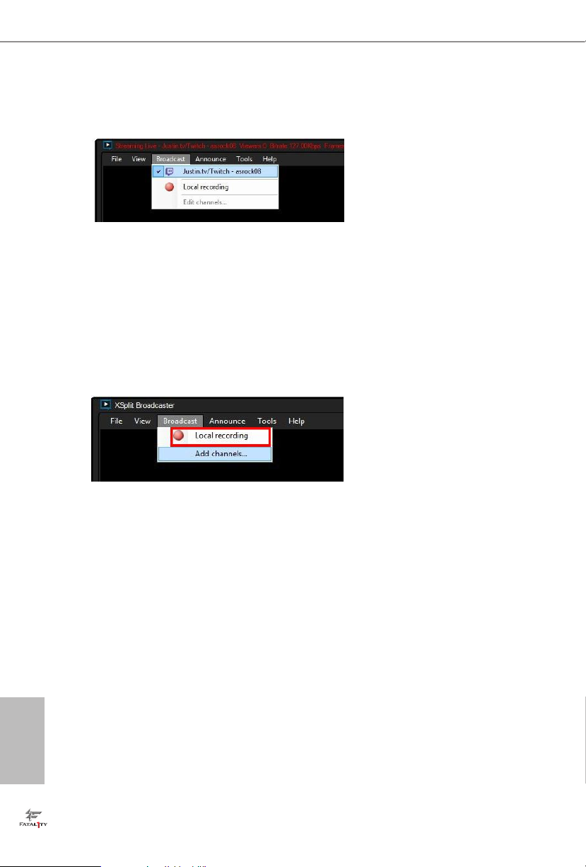
Step 8
Go to Broadcast and select the platform to enable live streaming.
A link to view your live Broadcast has been copied for you automatically.
Simply press CTRL-V or right click and choose Paste to paste the link into
the browser, and you can see your broadcast.
To disable live streaming, go to Broadcast again and deselect the platform.
3.5.2 Recording Your Gameplay
Step 1
Go to Broadcast > Local recording to start recording.
Step 2
To stop recording, Go to Broadcast again and deselect Local recording.
English
46
Step 3
Go to Tools > My Recordings...to access your recordings

Fatal1ty FM2A88X+ Killer Series
4. UEFI SETUP UTILITY
4.1 Introduction
ASRock Interactive UEFI is a blend of system conguration tools, cool sound ef-
fects and stunning visuals. Not only will it make BIOS setup less difcult but also a
lot more amusing. This section explains how to use the UEFI SETUP UTILITY to
congure your system. The UEFI chip on the motherboard stores the UEFI SETUP
UTILITY. You may run the UEFI SETUP UTILITY when you start up the computer.
Please press <F2> or <Delete> during the Power-On-Self-Test (POST) to enter the
UEFI SETUP UTILITY, otherwise, POST will continue with its test routines.
If you wish to enter the UEFI SETUP UTILITY after POST, restart the system by
pressing <Ctl> + <Alt> + <Delete>, or by pressing the reset button on the system
chassis. You may also restart by turning the system off and then back on.
Because the UEFI software is constantly being updated, the
following UEFI setup screens and descriptions are for reference
purpose only, and they may not exactly match what you see on
your screen.
4.1.1 UEFI Menu Bar
The top of the screen has a menu bar with the following selections:
Main For setting system time/date information
OC Tweaker For overclocking congurations
Advanced For advanced system congurations
Tool Useful tools
H/W Monitor Displays current hardware status
Boot For conguring boot settings and boot priority
Security For security settings
Exit Exit the current screen or the UEFI SETUP UTILITY
Use < > key or < > key to choose among the selections on the menu
bar, and use < > key or < > key to move the cursor up or down to
select items, then press <Enter> to get into the sub screen. You can also
navigate with a mouse.
47
English

4.1.2 Navigation Keys
Please check the following table for the function description of each navigation
key.
Navigation Key(s) Function Description
/ Moves cursor left or right to select Screens
/ Moves cursor up or down to select items
+ / - To change option for the selected items
<Tab> Switch to next function
<Enter> To bring up the selected screen
<PGUP> Go to the previous page
<PGDN> Go to the next page
<HOME> Go to the top of the screen
<END> Go to the bottom of the screen
<F1> To display the General Help Screen
<F7> Discard changes and exit the UEFI SETUP UTILITY
<F9> Load optimal default values for all the settings
<F10> Save changes and exit the UEFI SETUP UTILITY
<F12> Print screen
<ESC> Jump to the Exit Screen or exit the current screen
4.2 Main Screen
When you enter the UEFI SETUP UTILITY, the Main screen will appear and display
the system overview.
English
48
Active Page on Entry
This allows you to select the default page when entering UEFI setup utility.

Fatal1ty FM2A88X+ Killer Series
4.3 OC Tweaker Screen
In the OC Tweaker screen, you can set up overclocking features.
CPU Conguration
Overclock Mode
Use this to select Overclock Mode. Configuration options: [Auto] and
[Manual]. The default value is [Auto].
Spread Spectrum
This item should always be [Auto] for better system stability.
AMD Turbo Core Technology
This item appears only when the processor you adopt supports this fea-
ture. Use this to select enable or disable AMD Turbo Core Technology.
Conguration options: [Enabled] and [Disabled]. The default value is
[Enabled].
AMD Application power Management
Application Power Management (APM) ensures that average power con-
sumption over a thermally significant time period remains at or below
the TDP for the CPU mode being used. If [Enabled] is selected, the power
consumption is reduced when overclocking.
Processor Maximum Frequency
It will display Processor Maximum Frequency for reference.
Processor Maximum Voltage
It will display Processor Maximum Voltage for reference.
Multiplier/Voltage Change
This item is set to [Auto] by default. If it is set to [Manual], you may adjust
the value of Processor Frequency and Processor Voltage. However, it is
recommended to keep the default value for system stability.
APU Load-line Calibration
APU Load-line Calibration helps prevent APU voltage droop when the
system is under heavy load.
English
49

NB Load-line Calibration
NB Load-line Calibration helps prevent NB voltage droop when the
system is under heavy load.
GFX Engine Clock
Use this to adjust GFX Engine Clock. The default value is [Auto].
DRAM Timing Conguration
DRAM Frequency
If [Auto] is selected, the motherboard will detect the memory module(s)
inserted and assigns appropriate frequency automatically.
English
50

Fatal1ty FM2A88X+ Killer Series
DRAM Timing Control
DRAM Slot
Use this item to view SPD data.
DRAM Timing Control
Use this item to control DRAM timing.
Power Down Enable
Use this item to enable or disable DDR power down mode.
Bank Interleaving
Interleaving allows memory accesses to be spread out over banks on the
same node, or accross nodes, decreasing access contention.
Channel Interleaving
It allows you to enable Channel Memory Interleaving. Configuration
options: [Disabled], [Auto]. The default value is [Auto].
Voltage Conguration
DRAM Voltage
Use this to select DRAM Voltage. The default value is [Auto].
English
51

4.4 Advanced Screen
In this section, you may set the congurations for the following items: CPU Conguration, Nouth Bridge Conguration, South Bridge Conguration, Storage Congura-
tion, Super IO Conguration, ACPI Conguration, USB Conguration and Trusted
Computing.
Setting wrong values in this section may cause
the system to malfunction.
English
52

Fatal1ty FM2A88X+ Killer Series
4.4.1 CPU Conguration
Core C6 Mode
Use this item to enable or disable Core C6 mode. The default value is
[Enabled].
Cool ‘n’ Quiet
Use this item to enable or disable AMD’s Cool ‘n’ QuietTM technology. The
default value is [Enabled]. Conguration options: [Enabled] and [Disabled].
If you install Windows® 8 / 7 and want to enable this function, please set
this item to [Enabled]. Please note that enabling this function may reduce
CPU voltage and memory frequency, and lead to system stability or compatibility issue with some memory modules or power supplies. Please set
this item to [Disable] if above issue occurs.
SVM
When this option is set to [Enabled], a VMM (Virtual Machine Architecture)
can utilize the additional hardware capabilities provided by AMD-V. The
default value is [Enabled]. Conguration options: [Enabled] and [Disabled].
CPU Thermal Throttle
Use this item to enable CPU internal thermal control mechanism to keep
the CPU from overheated. The default value is [Auto].
53
English

4.4.2 North Bridge Conguration
IOMMU
This allows you to enable or disable IOMMU support.
Primary Graphics Adapter
This item will switch the PCI Bus scanning order while searching for video
card. It allows you to select the type of Primary VGA in case of multiple
video controllers. The default value of this feature is [PCI Express]. Con-
guration options: [Onboard], [PCI] and [PCI Express].
Share Memory
This allows you to set the share memory feature. The default value is [Auto].
Conguration options: [Auto], [32MB], [64MB], [128MB], [256MB] [512MB],
[1GB] and [2GB].
Onboard HDMI HD Audio
This allows you to enable or disable the “Onboard HDMI HD Audio” feature.
DVI Function
Use this to select DVI function when you install the DVI to HDMI adapter
to DVI port. Conguration options: [as Dual Link DVI] and [as HDMI]. If you
select [as Dual Link DVI], you can use Dual Link DVI monitor without au-
dio function. If you select [as HDMI], you can use HDMI monitor with audio
function. The default value is [as Dual Link DVI].
English
54

Fatal1ty FM2A88X+ Killer Series
4.4.3 South Bridge Conguration
Onboard HD Audio
Select [Auto], [Enabled] or [Disabled] for the onboard HD Audio feature. If
you select [Auto], the onboard HD Audio will be disabled when PCI Sound
Card is plugged.
Front Panel
Select [Auto] or [Disabled] for the onboard HD Audio Front Panel.
Onboard LAN
This allows you to enable or disable the onboard LAN feature.
Good Night LED
Enable this option to turn off Power LED when the system is power on.
The keyboard LED will also be turned off in S1, S3 and S4 state.
The default value is [Auto].
55
English

4.4.4 Storage Conguration
SATA Controller
Use this item to enable or disable the “SATA Controller” feature.
SATA Mode
Use this item to adjust SATA Mode. The default value of this option is [AHCI
Mode]. Conguration options: [AHCI Mode], [RAID Mode] and [IDE Mode].
If you set this item to RAID mode, it is suggested to install SATA
ODD driver on SATA3_5, SATA3_6, SATA3_7 and SATA3_8
ports.
AMD AHCI BIOS ROM
Use this item to enable or disable AMD AHCI BIOS ROM. The default
value of this option is [Disabled].
SATA IDE Combined Mode
This item is for SATA3_5, SATA3_6, SATA3_7 and SATA3_8.
Use this item to enable or disable SATA IDE combined mode. The default
value is [Enabled].
English
56
If you want to build RAID on SATA3_5, SATA3_6, SATA3_7 and
SATA3_8 ports, please disable this item.
Hard Disk S.M.A.R.T.
Use this item to enable or disable the S.M.A.R.T. (Self-Monitoring, Analy-
sis, and Reporting Technology) feature. Conguration options: [Disabled],
[Auto], [Enabled].

Fatal1ty FM2A88X+ Killer Series
4.4.5 Super IO Conguration
PS2 Y-Cable
Enable the PS2 Y-Cable or set this option to Auto.
Serial Port
Use this item to enable or disable the onboard serial port.
Serial Port Address
Use this item to set the address for the onboard serial port.
Conguration options: [3F8h / IRQ4] and [3E8h / IRQ4].
57
English

English
4.4.6 ACPI Conguration
Suspend to RAM
Use this item to select whether to auto-detect or disable the Suspend-toRAM feature. Select [Auto] will enable this feature if the OS supports it.
Check Ready Bit
Enable to enter the operating system after S3 only when the hard disk is
ready, this is recommended for better system stability.
Deep Sleep
Congure deep sleep mode for power saving when the computer is shut
down. We recommend disabling Deep Sleep for better system compatibility and stability.
Restore on AC/Power Loss
This allows you to set the power state after an unexpected AC/power loss.
If [Power Off] is selected, the AC/power remains off when the power recovers. If [Power On] is selected, the AC/power resumes and the system
starts to boot up when the power recovers.
PS/2 Keyboard Power On
Use this item to enable or disable PS/2 keyboard to turn on the system
from the power-soft-off mode.
PCI Devices Power On
Use this item to enable or disable PCI devices to turn on the system from
the power-soft-off mode.
Ring-In Power On
Use this item to enable or disable Ring-In signals to turn on the system
from the power-soft-off mode.
RTC Alarm Power On
Use this item to enable or disable RTC (Real Time Clock) to power on the
system.
58

Fatal1ty FM2A88X+ Killer Series
USB Keyboard/Remote Power On
Use this item to enable or disable USB Keyboard/Remote to power on the
system.
USB Mouse Power On
Use this item to enable or disable USB Mouse to power on the system.
ACPI HPET table
Use this item to enable or disable ACPI HPET Table. The default value is
[Enabled]. Please set this option to [Enabled] if you plan to use this motherboard to submit Windows® certication.
59
English

4.4.7 USB Conguration
USB 2.0 Controller
Use this item to enable or disable the use of USB 2.0 controller.
A88X USB 3.0 Controller
Use this item to enable or disable the use of USB 3.0 controller.
Legacy USB Support
Use this option to select legacy support for USB devices. There are four
con guration options: [Enabled], [Auto], [Disabled] and [UEFI Setup Only].
The default value is [Enabled]. Please refer to below descriptions for the
details of these four options:
[Enabled] - Enables support for legacy USB.
[Auto] - Enables legacy support if USB devices are connected.
[Disabled] - USB devices are not allowed to use under legacy OS and
UEFI setup when [Disabled] is selected. If you have USB compatibility is-
sue, it is recommended to select [Disabled] to enter OS.
[UEFI Setup Only] - USB devices are allowed to use only under UEFI
setup and Windows / Linux OS.
Legacy USB 3.0 Support
Use this option to enable or disable legacy support for USB 3.0 devices.
The default value is [Enabled].
English
60

Fatal1ty FM2A88X+ Killer Series
4.4.8 Trusted Computing
Security Device Support
Enable to activate Trusted Platform Module (TPM) security for your hard
disk drives.
61
English

4.5 Tool
System Browser
System Browser can let you easily check your current system conguration in UEFI setup.
OMG(Online Management Guard)
Administrators are able to establish an internet curfew or restrict internet
access at specied times via OMG. You may schedule the starting and
ending hours of internet access granted to other users. In order to prevent
users from bypassing OMG, guest accounts without permission to modify
the system time are required.
UEFI Tech Service
Contact ASRock Tech Service if you are having trouble with your PC.
Please setup network conguration before using UEFI Tech Service.
Easy RAID Installer
Easy RAID Installer helps you to copy the RAID driver from the support
CD to your USB storage device. After copying the drivers please change
the SATA mode to RAID, then you can start installing the operating system in RAID mode.
Easy Driver Installer
For users that don’t have an optical disk drive to install the drivers from
our support CD, Easy Driver Installer is a handy tool in the UEFI that
installs the LAN driver to your system via an USB storage device, then
downloads and installs the other required drivers automatically.
English
62
UEFI Update Utility
Instant Flash
Instant Flash is a UEFI ash utility embedded in Flash ROM. This convenient UEFI update tool allows you to update system UEFI without entering
operating systems rst like MS-DOS or Windows®. Just save the new

Fatal1ty FM2A88X+ Killer Series
UEFI le to your USB ash drive, oppy disk or hard drive and launch this
tool, then you can update your UEFI only in a few clicks without prepar-
ing an additional oppy diskette or other complicated ash utility. Please
be noted that the USB ash drive or hard drive must use FAT32/16/12 le
system. If you execute Instant Flash utility, the utility will show the UEFI
les and their respective information. Select the proper UEFI le to update your UEFI, and reboot your system after the UEFI update process is
completed.
Internet Flash
Internet Flash searches for available UEFI firmware updates from our
servers. In other words, the system can auto-detect the latest UEFI from
our servers and ash them without entering Windows OS.
Network Conguration
Internet Setting
Use this item to set up the internet connection mode. Conguration
options: [DHCP (Auto IP)] and [PPPOE].
UEFI Download Server
Use this item to select UEFI rmware download server for Internet Flash.
Conguration options: [Asia], [Europe], [USA] and [China].
Dehumidier Function
Users may prevent motherboard damages due to dampness by enabling
“Dehumidier Function”. When enabling Dehumidier Function, the computer will power on automatically to dehumidify the system after entering
S4/S5 state.
English
63

Dehumidier Period
This allows users to congure the period of time until the computer powers
on and enables “Dehumidier” after entering S4/S5 state.
Dehumidier Duration
This allows users to congure the duration of the dehumidifying process
before it returns to S4/S5 state.
Dehumidier CPU Fan Setting
Use this setting to congure CPU fan speed while “Dehumidier” is en-
abled.
Would you like to save current setting user defaults?
In this option, you are allowed to load and save three user defaults
according to your own requirements.
English
64

Fatal1ty FM2A88X+ Killer Series
4.6 Hardware Health Event Monitoring Screen
In this section, it allows you to monitor the status of the hardware on your system,
including the parameters of the CPU temperature, motherboard temperature, CPU
fan speed, chassis fan speed, and the critical voltage.
CPU Fan 1 & 2 Setting
This allows you to set the CPU fan 1 & 2 speed. Conguration options: [Full
On] and [Automatic Mode]. The default is value [Full On].
Chassis Fan 1 Setting
This allows you to set the chassis fan 1 speed. Con guration options: [Full
On], [Manual Mode] and [Automatic Mode]. The default is value [Full On].
Chassis Fan 2 Setting
This allows you to set the chassis fan 2 speed. Con guration options: [Full
On] and [Manual Mode]. The default is value [Full On].
Chassis Fan 3 Setting
This allows you to set the chassis fan 3 speed. Con guration options: [Full
On] and [Manual Mode]. The default is value [Full On].
Over Temperature Protection
Use this item to enable or disable Over Temperature Protection. The
default value is [Enabled].
65
English

4.7 Boot Screen
In this section, it will display the available devices on your system for you to congure the boot settings and the boot priority.
Fast Boot
Fast Boot minimizes your computer’s boot time. There are three con-
guration options: [Disabled], [Fast] and [Ultra Fast]. The default value is
[Disabled]. Please refer to below descriptions for the details of these three
options:
[Disabled] - Disable Fast Boot.
[Fast] - The only restriction is you may not boot by using an USB ash
drive.
[Ultra Fast] - There are a few restrictions.
1. Only supports Windows® 8 UEFI operating system.
2. You will not be able to enter BIOS Setup (Clear CMOS or run utility
in Widows® to enter BIOS Setup).
3. If you are using an external graphics card, the VBIOS must support
UEFI GOP in order to boot.
English
66
Boot From Onboard LAN
Use this item to enable or disable the Boot From Onboard LAN feature.
Setup Prompt Timeout
This shows the number of seconds to wait for setup activation key.
Bootup Num-Lock
If this item is set to [On], it will automatically activate the Numeric Lock
function after boot-up.
Full Screen Logo
Use this item to enable or disable OEM Logo. The default value is [Enabled].

Fatal1ty FM2A88X+ Killer Series
Option ROM Messages
[Force BIOS] - The third-party ROM messages will be forced to display
during the bootsequence.
[Keep Current] - The third-party ROM messages will be displayed only if
the third-partymanufacturer had set the add-on device to do so.
Boot Failure Guard
Enable or disable the feature of Boot Failure Guard.
Boot Failure Guard Count
Enable or disable the feature of Boot Failure Guard Count.
CSM (Compatibility Support Module)
CSM
Enable to launch the Compatibility Support Module. Please do not disable
unless you’re running a WHCK test. If you are using Windows
and all of your devices support UEFI, you may also disable CSM for faster
boot speed.
Launch PXE OpROM Policy
Select UEFI only to run those that support UEFI option ROM only. Select
Legacy only to run those that support legacy option ROM only. Do not
launch?
Launch Storage OpROM Policy
Select UEFI only to run those that support UEFI option ROM only. Select
Legacy only to run those that support legacy option ROM only. Do not
launch?
Launch Video OpROM Policy
Select UEFI only to run those that support UEFI option ROM only. Select
Legacy only to run those that support legacy option ROM only. Do not
launch?
®
8 64-bit
English
67

4.8 Security Screen
In this section, you may set or change the supervisor/user password for the system.
For the user password, you may also clear it.
Secure Boot
Enable to support Windows® 8 Secure Boot.
English
68

4.9 Exit Screen
Save Changes and Exit
When you select this option, it will pop-out the following message, “Save
conguration changes and exit setup?” Select [OK] to save the changes
and exit the UEFI SETUP UTILITY.
Discard Changes and Exit
When you select this option, it will pop-out the following message, “Discard
changes and exit setup?” Select [OK] to exit the UEFI SETUP UTILITY
without saving any changes.
Discard Changes
When you select this option, it will pop-out the following message, “Discard
changes?” Select [OK] to discard all changes.
Load UEFI Defaults
Load UEFI default values for all the setup questions. F9 key can be used
for this operation.
Fatal1ty FM2A88X+ Killer Series
69
English

Contact Information
If you need to contact ASRock or want to know more about ASRock, you’re
welcome to visit ASRock’s website at http://www.asrock.com; or you may
contact your dealer for further information. For technical questions, please
submit a support request form at http://www.asrock.com/support/tsd.asp
ASRock Incorporation
2F., No.37, Sec. 2, Jhongyang S. Rd., Beitou District,
Taipei City 112, Taiwan (R.O.C.)
ASRock EUROPE B.V.
Bijsterhuizen 3151
6604 LV Wijchen
The Netherlands
Phone: +31-24-345- 44 -33
Fax: +31-24-345-44-38
ASRock America, Inc.
13848 Magnolia Ave, Chino, CA91710
U.S.A.
Phone: +1-909-590-8308
English
70
Fax: +1-909-590-1026
 Loading...