


B150 Gaming K4
User Manual
Version 1.0
Published June 2015
Copyright©2015 ASRock INC. All rights reserved.

Version 1.1
Published February 2016
Copyright©2016 ASRock INC. All rights reserved.
Copyright Notice:
No part of this documentation may be reproduced, transcribed, transmitted, or
translated in any language, in any form or by any means, except duplication of
documentation by the purchaser for backup purpose, without written consent of
ASRock Inc.
Products and corporate names appearing in this documentation may or may not
be registered trademarks or copyrights of their respective companies, and are used
only for identication or explanation and to the owners’ benet, without intent to
infringe.
Disclaimer:
Specications and information contained in this documentation are furnished for
informational use only and subject to change without notice, and should not be
constructed as a commitment by ASRock. ASRock assumes no responsibility for
any errors or omissions that may appear in this documentation.
With respect to the contents of this documentation, ASRock does not provide
warranty of any kind, either expressed or implied, including but not limited to
the implied warranties or conditions of merchantability or tness for a particular
purpose.
In no event shall ASRock, its directors, ocers, employees, or agents be liable for
any indirect, special, incidental, or consequential damages (including damages for
loss of prots, loss of business, loss of data, interruption of business and the like),
even if ASRock has been advised of the possibility of such damages arising from any
defect or error in the documentation or product.
is device complies with Part 15 of the FCC Rules. Operation is subject to the following
two conditions:
(1) this device may not cause harmful interference, and
(2) this device must accept any interference received, including interference that
may cause undesired operation.
CALIFORNIA, USA ONLY
e Lithium battery adopted on this motherboard contains Perchlorate, a toxic substance
controlled in Perchlorate Best Management Practices (BMP) regulations passed by the
California Legislature. When you discard the Lithium battery in California, USA, please
follow the related regulations in advance.
“Perchlorate Material-special handling may apply, see ww w.dtsc.ca.gov/hazardouswaste/
perchlorate”
ASRock Website: http://www.asrock.com

AUSTRALIA ONLY
Our goods come with guarantees that cannot be excluded under the Australian Consumer
Law. You are entitled to a replacement or refund for a major failure and compensation for
any other reasonably foreseeable loss or damage caused by our goods. You are also entitled
to have the goods repaired or replaced if the goods fail to be of acceptable quality and the
failure does not amount to a major failure. If you require assistance please call ASRock Tel
: +886-2-28965588 ext.123 (Standard International call charges apply)
Manufactured under license under U.S. Patent Nos: 5,956,674; 5,974,380; 6,487,535;
7,003,467 & other U.S. and worldwide patents issued & pending. DTS, the Symbol, &
DTS and the Symbol together is a registered trademark & DTS Connect, DTS Interactive,
DTS Neo:PC are trademarks of DTS, Inc. Product includes soware.
© DTS, Inc., All Rights Reserved.

Fatal1ty Story
Who knew that at age 19, I would be a World Champion PC gamer. When I was 13, I actually
played competitive billiards in professional tournaments and won four or ve games o guys
who played at the highest level. I actually thought of making a career of it, but at that young
age situations change rapidly. Because I’ve been blessed with great hand-eye coordination and
a grasp of mathematics (an important element in video gaming) I gravitated to that activity.
GOING PRO
I started professional gaming in 1999 when I entered the CPL (Cyberathlete Professional
League) tournament in Dallas and won $4,000 for coming in third place. Emerging as one
of the top players in the United States, a company interested in sponsoring me ew me to
Sweden to compete against the top 12 players in the world. I won 18 straight games, lost
none, and took rst place, becoming the number one ranked Quake III player in the world
in the process. Two months later I followed that success by traveling to Dallas and defending
my title as the world’s best Quake III player, winning the $40,000 grand prize. From there
I entered competitions all over the world, including Singapore, Korea, Germany, Australia,
Holland and Brazil in addition to Los Angeles, New York and St. Louis.
WINNING STREAK
I was excited to showcase my true gaming skills when defending my title as CPL
Champion of the year at the CPL Winter 2001 because I would be competing in a totally
dierent rst person shooter (fps) game, Alien vs. Predator II. I won that competition and
walked away with a new car. e next year I won the same title playing Unreal Tournament
2003, becoming the only three-time CPL champion of the year. And I did it playing a
different game each year, something no one else has ever done and a feat of which I am
extremely proud.
At QuakeCon 2002, I faced o against my rival ZeRo4 in one of the most highly
anticipated matches of the year, winning in a 14 to (-1) killer victory. Competing at Quakecon
2004, I became the World’s 1st Doom3 Champion by defeating Daler in a series of very
challenging matches and earning $25,000 for the victory.
Since then Fatal1ty has traveled the globe to compete against the best in the world, winning
prizes and acclaim, including the 2005 CPL World Tour Championship in New York City for
a $150,000 rst place triumph. In August 2007, Johnathan was awarded the rst ever Lifetime
Achievement Award in the four year history of the eSports-Award for “showing exceptional
sportsmanship, taking part in shaping eSports into what it is today and for being the prime
representative of this young sport. He has become the gurehead for eSports worldwide”.

LIVIN’ LARGE
Since my rst big tournament wins, I have been a “Professional Cyberathlete”, traveling the
world and livin’ large with lots of International media coverage on outlets such as MTV,
ESPN and a 60 Minutes segment on CBS to name only a few. It's unreal - it's crazy. I’m living
a dream by playing video games for a living. I’ve always been athletic and took sports like
hockey and football very seriously, working out and training hard. is discipline helps me
become a better gamer and my drive to be the best has opened the doors necessary to become
a professional.
A DREAM
Now, another dream is being realized – building the ultimate gaming computer, made
up of the best parts under my own brand. Quality hardware makes a huge difference in
competitions…a couple more frames per second and everything gets really nice. It’s all about
getting the computer processing faster and allowing more uid movement around the maps.
My vision for Fatal1ty hardware is to allow gamers to focus on the game without worrying
about their equipment, something I’ve preached since I began competing. I don’t want to
worry about my equipment. I want to be there – over and done with - so I can focus on
the game. I want it to be the fastest and most stable computer equipment on the face of the
planet, so quality is what Fatal1ty Brand products represent.
Johnathan “Fatal1ty” Wendel
e Fatal1ty name, Fatal1ty logos and the Fatal1ty likeness are registered trademarks of Fatal1ty, Inc., and are used
under license. © 2016 Fatal1ty, Inc. All rights reserved. All other trademarks are the property of their respective
owners.

Contents
Chapter 1 Introduction 1
1.1 Package Contents 1
1.2 Specications 2
1.3 Motherboard Layout 6
1.4 I/O Panel 8
Chapter 2 Installation 10
2.1 Installing the CPU 11
2.2 Installing the CPU Fan and Heatsink 14
2.3 Installing Memory Modules (DIMM) 15
2.4 Expansion Slots (PCI Express Slots) 17
2.5 Jumpers Setup 18
2.6 Onboard Headers and Connectors 19
2.7 CrossFireXTM and Quad CrossFireXTM Operation Guide 24
2.7.1 Installing Two CrossFireXTM-Ready Graphics Cards 24
2.7.2 Driver Installation and Setup 26
Chapter 3 Software and Utilities Operation 27
3.1 Installing Drivers 27
3.2 F-Stream 28
3.2.1 Installing F-Stream 28
3.2.2 Using F-Stream 28
3.3 ASRock Live Update & APP Shop 32
3.3.1 UI Overview 32

3.3.2 Apps 33
3.3.3 BIOS & Drivers 36
3.3.4 Setting 37
3.4 XSplit Broadcaster 38
3.4.1 Live Streaming Your Gameplay 38
3.5.2 Recording Your Gameplay 41
3.5 Enabling USB Ports for Windows® 7 Installation 42
Chapter 4 UEFI SETUP UTILITY 45
4.1 Introduction 45
4.2 EZ Mode 46
4.3 Advanced Mode 47
4.3.1 UEFI Menu Bar 47
4.3.2 Navigation Keys 48
4.4 Main Screen 49
4.5 OC Tweaker Screen 50
4.6 Advanced Screen 59
4.6.1 CPU Conguration 60
4.6.2 Chipset Conguration 62
4.6.3 Storage Conguration 64
4.6.4 Super IO Conguration 65
4.6.5 ACPI Conguration 66
4.6.6 USB Conguration 68
4.6.7 Trusted Computing 69
4.7 Tools 70

4.8 Hardware Health Event Monitoring Screen 73
4.9 Security Screen 75
4.10 Boot Screen 76
4.11 Exit Screen 79
Chapter 5: Net Framework Installation Guide 80
5.1 Installing .Net Framework 3.5.1 (For Server 2008 R2) 80

Fatal1ty E3V5 Performance Gaming/OC Series
Chapter 1 Introduction
ank you for purchasing ASRock Fatal1ty E3V5 Performance Gaming/OC Series
motherboard, a reliable motherboard produced under ASRock’s consistently
stringent quality control. It delivers excellent performance with robust design
conforming to ASRock’s commitment to quality and endurance.
In this documentation, Chapter 1 and 2 contains the introduction of the
motherboard and step-by-step installation guides. Chapter 3 contains the operation
guide of the soware and utilities. Chapter 4 contains the conguration guide of
the BIOS setup.
Becau se the motherboard specications and the BIOS soware might be updated, the
content of this documentation will be subject to change without notice. In case any modications of this documentation occur, the updated version will be available on ASRock’s
website w ithout further notice. If you require technical support relate d to this motherboard, please visit our website for specic information about the model you are using. You
may nd the l atest VGA cards and CPU support list on ASRock ’s website a s well. ASRock
website http://www.asrock.com.
1.1 Package Contents
• ASRock Fatal1ty E3V5 Performance Gaming/OC Series Motherboard (ATX Form
Factor)
• ASRock Fatal1ty E3V5 Performance Gaming/OC Series Quick Installation Guide
• ASRock Fatal1ty E3V5 Performance Gaming/OC Series Support CD
• 2 x Serial ATA (SATA) Data Cables (Optional)
• 1 x I/O Panel Shield
English

1.2 Specications
Platform
CPU
Chipset
Memory
Expansion
Slot
• ATX Form Factor
• Supports the Intel® Xeon® E3-1200 v5 Processor and 6th
Generation Intel® CoreTM i3/Pentium®/Celeron® Processors
(Socket 1151)
• Digi Power design
• 10 Power Phase design
• Supports Intel® Turbo Boost 2.0 Technology
• Supports ASRock BCLK Full-range Overclocking
• Supports ASRock Hyper BCLK Engine
• Intel® C232
• Dual Channel DDR4 Memory Technology
• 4 x DDR4 DIMM Slots
• Supports DDR4 2800*(OC)/2400(OC)/2133 non-ECC, un-
buered memory
• Supports ECC UDIMM memory modules
• Max. capacity of system memory: 64GB
• Supports Intel® Extreme Memory Prole (XMP) 2.0
• 15μ Gold Contact in DIMM Slots
• 2 x PCI Express 3.0 x16 Slots (PCIE2: x16 mode; PCIE4: x4
mode)*
* Supports NVMe SSD as boot disks
• 3 x PCI Express 3.0 x1 Slots (Flexible PCIe)
• Supports AMD Quad CrossFireXTM and CrossFireXTM
• 15μ Gold Contact in VGA PCIe Slot (PCIE2)
English
2 3

Fatal1ty E3V5 Performance Gaming/OC Series
Audio
LAN
Rear Panel
I/O
• 7.1 CH HD Audio with Content Protection (Realtek
ALC1150 Audio Codec)
• Premium Blu-ray Audio support
• Supports Surge Protection (ASRock Full Spike Protection)
• Supports Purity SoundTM 3
- Nichicon Fine Gold Series Audio Caps
- 115dB SNR DAC with Dierential Amplier
- TI® NE5532 Premium Headset Amplier (Supports up to
600 Ohm headsets)
- Pure Power-In
- Direct Drive Technology
- PCB Isolate Shielding
• Supports DTS Connect
• Gigabit LAN 10/100/1000 Mb/s
• Giga PHY Intel® I219V
• Supports Wake-On-LAN
• Supports Lightning/ESD Protection (ASRock Full Spike
Protection)
• Supports Energy Ecient Ethernet 802.3az
• Supports PXE
• 1 x PS/2 Mouse/Keyboard Port
• 1 x Optical SPDIF Out Port
• 1 x USB 2.0 Port (Supports ESD Protection (ASRock Full
Spike Protection))
• 1 x Fatal1ty Mouse Port (USB 2.0) (Supports ESD Protection
(ASRock Full Spike Protection))
• 4 x USB 3.0 Ports (Supports ESD Protection (ASRock Full
Spike Protection))
• 1 x RJ-45 LAN Port with LED (ACT/LINK LED and SPEED
LED)
• HD Audio Jacks: Rear Speaker / Central / Bass / Line in /
Front Speaker / Microphone
English

Storage
• 6 x SATA3 6.0 Gb/s Connectors, support RAID (RAID 0,
RAID 1, RAID 5, RAID 10, Intel Rapid Storage Technology
enterprise), NCQ, AHCI and Hot Plug
Connector
BIOS
Feature
• 1 x COM Port Header
• 1 x TPM Header
• 1 x Power LED and Speaker Header
• 2 x CPU Fan Connectors (4-pin) (Smart Fan Speed Control)
• 4 x Chassis Fan Connectors (4-pin) (Smart Fan Speed Con-
trol)
* CPU_FAN1 and CHA_FAN1 can auto detect if 3-pin or
4-pin fan is in use.
* e CPU Fan Connector supports the CPU fan of ma xi-
mum 1A (12W) fan power.
• 1 x 24 pin ATX Power Connector
• 1 x 8 pin 12V Power Connector
• 1 x PCIe Power Connector
• 1 x Front Panel Audio Connector
• 2 x USB 2.0 Headers (Support 4 USB 2.0 ports) (Supports
ESD Protection (ASRock Full Spike Protection))
• 1 x USB 3.0 Header (Supports 2 USB 3.0 ports) (Supports
ESD Protection (ASRock Full Spike Protection))
• AMI UEFI Legal BIOS with multilingual GUI support
• ACPI 5.0 Compliant wake up events
• SMBIOS 2.7 Support
• CPU, GT_CPU, DRAM, VPPM, PCH 1.0V, VCCIO, VC-
CPLL, VCCSA Voltage Multi-adjustment
Hardware
Monitor
English
• CPU/Chassis temperature sensing
• CPU/Chassis Fan Tachometer
• CPU/Chassis Quiet Fan (Auto adjust chassis fan speed by
CPU temperature)
• CPU/Chassis Fan multi-speed control
• Voltage monitoring: +12V, +5V, +3.3V, CPU Vcore, GT_CPU,
DRAM, VPPM, PCH 1.0V, VCCIO, VCCSA
4 5

Fatal1ty E3V5 Performance Gaming/OC Series
OS
• Microso® Windows® 10 64-bit / 8.1 64-bit / 7 32-bit / 7 64-
bit
* To install Windows® 7 OS, a modied installation disk with
xHCI drivers packed into the ISO le is required. Please refer to
page 42 for more detailed instructions.
* For the updated Windows® 10 driver, please visit ASRock ’s
website for details: http://ww w.asrock.com.
Certications
* For detailed product information, please visit our website: http://www.asrock .com
Please realize that the re is a certain r isk involved with overclo cking, including adju sting
the setting in the BIOS, applying Untied Overclocking Technolog y, or using third-party
overclocking to ols. O verclocking may aect your system’s stability, or even cause damage to
the components and devices of your system. It should be done at your ow n risk and expense.
We are not responsibl e for possible damage caused by overclo cking.
• FCC, CE, WHQL
• ErP/EuP ready (ErP/EuP ready power supply is required)
English
DDR 4_A2 (6 4 bit, 28 8-pin m odule )
DDR 4_A1 (6 4 bit, 28 8-pin m odule )
DDR 4_B2 (6 4 bit, 28 8-pin m odule )
DDR 4_B1 (6 4 bit, 28 8-pin m odule )
ATX12V1
USB 2. 0
T: USB1
B: USB 2
ATXP WR 1
LAN
PCIE2
Top:
RJ-45
USB 3.0
T: USB3
B: USB4
Top:
Central/Bass
Center :
REAR SPK
Top:
LINE IN
Center :
FRONT
Bottom :
Optica l
SPDIF
Bottom :
MIC IN
PCIE4
HDLED RESET
PLED PWRBTN
PANEL1
1
USB3_4
1
1
SPK_PLED1
COM1
1
1
HD_AUDIO1
E3V5 Performance Gaming/OC
PCIE1
RoHS
5
6
11
10
14
21
22
SATA3_1
1
3
2
20
Purity
Sound 3
TM
BIOS
ROM
PS2
Keybo ard
/Mous e
CMOS
Battery
CLRMOS1
1
PCIE3
4
USB3_7 _8
1
13
CPU_FAN2
CPU_FAN1
CHA_FAN1
CHA_FAN4
USB1_2
1
17
1
TPMS1
PCIE5
CHA_FAN2
CHA_FAN3
PCIE_PWR1
SATA3_5
SATA3_3
SATA3_4
SATA3_2
SATA3_0
7
8
9
12
15
16
18
19
23
Intel
C232
USB 3.0
T: USB1
B: USB2
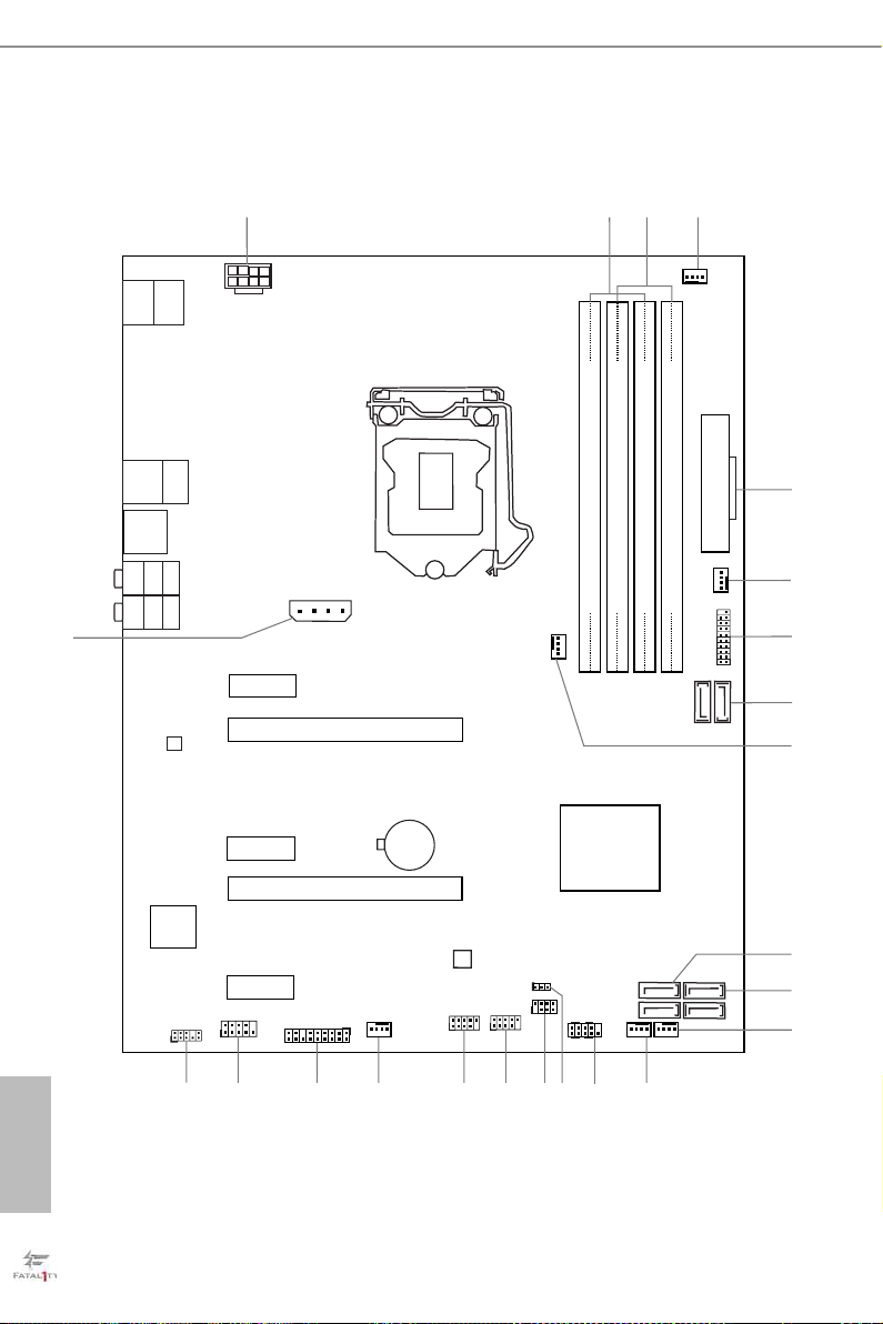
1.3 Motherboard Layout
English
6 7

Fatal1ty E3V5 Performance Gaming/OC Series
No. Description
1 ATX 12V Power Connector (ATX12V1)
2 2 x 288-pin DDR4 DIMM Slots (DDR4_A1, DDR4_B1)
3 2 x 288-pin DDR4 DIMM Slots (DDR4_A2, DDR4_B2)
4 CPU Fan Connector (CPU_FAN1)
5 ATX Power Connector (ATXPWR1)
6 Chassis Fan Connector (CHA_FAN4)
7 USB 3.0 Header (USB3_7_8)
8 SATA3 Connectors (SATA3_0_1)
9 CPU Fan Connector (CPU_FAN2)
10 SATA3 Connectors (SATA3_3_5)
11 SATA3 Connectors (SATA 3_ 2_4)
12 Chassis Fan Connector (CHA_FAN2)
13 Chassis Fan Connector (CHA_FAN1)
14 System Panel Header (PANEL1)
15 Clear CMOS Jumper (CLRMOS1)
16 Power LED and Speaker Header (SPK_PLED1)
17 USB 2.0 Header (USB1_2)
18 USB 2.0 Header (USB3_4)
19 Chassis Fan Connector (CHA _FAN3)
20 TPM Header (TPMS1)
21 COM Port Header (COM1)
22 Front Panel Audio Header (HD_AUDIO1)
23 PCIe Power Connector (PCIE_PWR1)
English

1.4 I/O Panel
4
6
1
2
12
No. Description No. Description
1 Fatal1ty Mouse Port (USB1) 7 Front Speaker (Lime)**
2 USB 2.0 Port (USB2) 8 Microphone (Pink)
3 LAN RJ-45 Port* 9 Optica l SPDIF Out Port
4 Central / Bass (Orange) 10 USB 3.0 Ports (USB3_34)
5 Rear Speaker (Black) 11 USB 3.0 Ports (USB3_12)
6 Line In (Light Blue) 12 PS/2 Mouse/Keyboard Port
CAU TION:
For operating system installation, be sure to plug your USB ash drive into the USB 2.0
Ports (USB12).
3 5
11
10
7
9
8
English
8 9

Fatal1ty E3V5 Performance Gaming/OC Series
* ere are two LEDs on each LAN port. Please refer to the table below for the LAN port LED indications .
ACT/LINK LED
SPEED LED
LAN Por t
Activity / Link LED Speed LED
Status Description Status Description
O No Link O 10Mbps connection
Blinking Data Activity Orange 100Mbps connection
On Link Green 1Gbps connection
** If you use a 2- channel speaker, plea se connect the speake r’s plug into “Front Speaker Jack”. See the table below
for connection d etails in accordance w ith the type of speaker you use.
Audio Output
Channels
Front Speaker
(No. 7)
Rear Speaker
(No. 5)
Central / Bass
(No. 4)
2 V -- -- --
4 V V -- --
6 V V V --
8 V V V V
To enable Multi-Streaming, you need to connect a front panel audio cable to the front
panel au dio header. Aer re starting your computer, you will nd the “Mixe r” tool on your
system. Plea se sele ct “Mixe r To olBox” , click “Enable playback multi-stre aming”, and
click “ok”. Choose “2CH”, “4CH”, “6CH”, or “8CH” and then you are a llowed to select
“Realtek HDA Primary output” to use the Rear Spea ker, Cent ral/Ba ss, and Front Speaker,
or select “Realtek HDA Audio 2nd output” to use the front panel audio.
Line In
(No. 6)
English

Chapter 2 Installation
is is an ATX form factor motherboard. Before you install the motherboard, study
the conguration of your chassis to ensure that the motherboard ts into it.
Pre-installation Precautions
Take note of the following precautions before you install motherboard components
or change any motherboard settings.
• Make sure to unplug the power cord before installing or removing the motherboard
components. Failure to do so may cause physical injuries and damages to motherboard
components.
• In order to avoid damage from static electricity to the motherboard’s components,
NEVER place your motherboard directly on a carpet. Also remember to use a grounded
wrist strap or touch a safety grounded object before you handle the components.
• Hold components by the edges and do not touch the ICs.
• Whenever you uninstall any components, place them on a grounded anti-static pad or
in the bag that comes with the components.
• When placing screws to secure the motherboard to the chassis, please do not over-
tighten the screws! Doing so may damage the motherboard.
English
10 11

2.1 Installing the CPU
1. Before you insert the 1151-Pin CPU into the socket, pl ease check if the PnP cap is on the
socket, if the CPU surface is unclean, or if there are any bent pins in the socket. Do not
force to in sert the CPU into the socket if above situation is found. Otherwise, the CPU
will be seriously damaged.
2. Unplug all power c ables before in stalling the CPU.
1
Fatal1ty E3V5 Performance Gaming/OC Series
A
B
2
English

3
4
5
English
12 13

Fatal1ty E3V5 Performance Gaming/OC Series
Please save and replace the cover if the processor i s removed. e cover must be placed if
you wish to return the motherboard for aer service.
English

2.2 Installing the CPU Fan and Heatsink
1 2
FAN
CPU_
English
14 15

Fatal1ty E3V5 Performance Gaming/OC Series
2.3 Installing Memory Modules (DIMM)
is motherboard provides four 288-pin DDR4 (Double Data Rate 4) DIMM slots,
and supports Dual Channel Memory Technology.
1. For dual channel cong uration , you always need to in stall identical (the same b rand,
speed , size and chip-type) DDR4 DIMM pairs.
2. It is unable to activate Dual Channel Memor y Technology with only one or three memory
module installed.
3. It is not allowed to install a DDR, DDR2 or DDR3 memory module into a DDR4 sl ot;
otherwise , this motherboard and DIM M may be damaged.
Dual Channel Memory Conguration
Priority DDR4_A1 DDR4_A2 DDR4_B1 DDR4_B2
1 Populated Populated
2 Populated Populated
3 Populated Populated Populated Populated
e DIMM only ts in one correct orientation. It will cause permanent dam age to the
motherboard and the DIMM if you force the DIMM into the slot at incorrect orientation.
English

1
2
3
English
16 17

Fatal1ty E3V5 Performance Gaming/OC Series
2.4 Expansion Slots (PCI Express Slots)
ere are 5 PCI Express slots on the motherboard.
Before installing an ex pansion card, please make sure that the power supply is switched o
or the power cord is unplug ged. Pl ease read the documentation of the expansion card and
make necessary hardware settings for the card before you start the installation.
PCIe slots:
PCIE1 (PCIe 3.0 x1 slot) is used for PCI Express x1 lane width cards.
PCIE2 (PCIe 3.0 x16 slot) is used for PCI Express x16 lane width graphics cards
PCIE3 (PCIe 3.0 x1 slot) is used for PCI Express x1 lane width cards.
PCIE4 (PCIe 3.0 x16 slot) is used for PCI Express x4 lane width graphics cards.
PCIE5 (PCIe 3.0 x1 slot) is used for PCI Express x1 lane width cards
For a better ther mal environment, ple ase connect a ch assi s fan to the motherboard’s chassis fan connector (CHA_ FAN1, CHA_ FAN2, CHA_ FAN3 or CHA_FAN4) when u sing
multiple graphics cards.
English

2.5 Jumpers Setup
e illustration shows how jumpers are setup. When the jumper cap is placed on
the pins, the jumper is “Short”. If no jumper cap is placed on the pins, the jumper
is “Open”. e illustration shows a 3-pin jumper whose pin1 and pin2 are “Short”
when a jumper cap is placed on these 2 pins.
Clear CMOS Jumper
(CLRMO S1)
(see p.7, No. 15)
CLRMOS1 allows you to clear the data in CMOS. To clear and reset the system
parameters to default setup, please turn o the computer and unplug the power
cord from the power supply. Aer waiting for 15 seconds, use a jumper cap to
short pin2 and pin3 on CLRMOS1 for 5 seconds. However, please do not clear the
CMOS right aer you update the BIOS. If you need to clear the CMOS when you
just nish updating the BIOS, you must boot up the system rst, and then shut it
down before you do the clear-CMOS action. Please be noted that the password,
date, time, and user default prole will be cleared only if the CMOS battery is
removed.
Clear CMOSDefault
English
18 19

Fatal1ty E3V5 Performance Gaming/OC Series
2.6 Onboard Headers and Connectors
Onboard headers and connectors are NOT jumpers. Do NOT place jumper caps over these
heade rs and connectors. Placing jumper caps over the headers and connectors will cause
permanent damage to the motherboard.
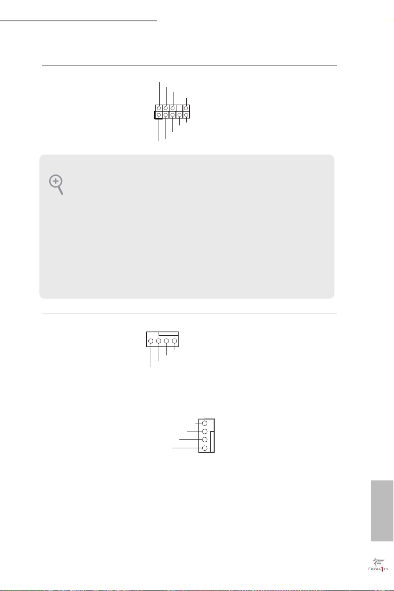
System Panel Header
(9-pi n PANEL1)
(see p.7, No. 14)
PWRBTN (Power Switch):
Connec t to the power switch on the chassi s front panel. You may congure the way to tur n
o your system using the power switch.
RESET (Reset Switch):
Connec t to the reset switch on the chassi s front panel. P ress the reset sw itch to restart the
computer if the computer f reezes and fails to perform a normal restar t.
PLED (Syste m Power LED):
Connec t to the power status indicator on the chassis front panel. e LED i s on when the
system is operating. e LED keeps blinking when the system is in S1/S3 sleep state. e
LED is o when the system is in S4 sleep state or powered o (S5).
HDLED (Ha rd Drive Activity LED):
Connec t to the hard drive ac tivity LED on the chassis front panel. e LED is on when the
hard drive is reading or wr iting data.
e front panel de sign may dier by chassis. A front pane l module mainly consists of power
switch, reset switch , power LED, hard dr ive activity LED, speaker and etc. When connecting your ch assi s front panel module to thi s header, make sure the wire a ssignments and the
pin assignments are matched correctly.
1
PLED+
PLED-
HDLED-
HDLED+
PWRBTN#
GND
RESET#
GND
GND
Connect the power
switch, reset switch and
system status indicator on
the chassis to this header
according to the pin
assignments below. Note
the positive and negative
pins before connecting
the cables.
English

Power LED and Speaker
SPEAKER
Header
(7-pin SPK_PLED1)
(see p.7, No. 16)
DUMMY
+5V
1
PLED+
DUMMY
PLED+
PLED-
Please connect the
chassis power LED and
the chassis speaker to this
header.
Serial ATA3 Connectors
(SATA3_0_1:
see p.7, No. 8)
(SATA3_2_4:
see p.7, No. 11)
(SATA3_3_5:
see p.7, No. 10)
USB 2.0 Headers
(9-pin USB1_2)
(see p.7, No. 17)
(9-pin USB3_4)
(see p.7, No. 18)
USB 3.0 Header
(19-pin USB3_7_8)
(see p.7, No. 7)
SATA3_5
SATA3_3
USB_PWR
1
USB_PWR
Vbus
IntA_PA_SSRX-
IntA_PA_SSRX+
GND
IntA_PA_SSTX-
IntA_PA_SSTX+
GND
IntA_PA_D-
IntA_PA_D+
SATA3_1
-B
-A
+B
GND
GND
+A
SATA3_4
SATA3_2
DUMMY
VbusVbus
IntA_PB_SSRX-
IntA_PB_SSRX+
GND
IntA_PB_SSTX-
IntA_PB_SSTX+
GND
IntA_PB_D-
IntA_PB_D+
Dummy
1
ese six SATA3
connectors support SATA
data cables for internal
SATA3_0
storage devices with up to
6.0 Gb/s data transfer rate.
ere are two headers
on this motherboard.
Each USB 2.0 header can
support two ports.
Besides four USB 3.0
ports on the I/O panel,
there is one header on this
motherboard. Each USB
3.0 header can support
two ports.
English
20 21
Fatal1ty E3V5 Performance Gaming/OC Series
1
GND
PRESENCE#
MIC2_R
MIC2_L
MIC_RET
J_SENSE
OUT2_R
OUT_RET
OUT2_L
is header is for
connecting audio devices
to the front audio panel.
Front Panel Audio Header
(9-pin HD_ AUDIO1)
(see p.7, No. 22)
1. High Denition Audio support s Jack Sensing , but the panel wire on the cha ssis must sup port HDA to function correctly. Ple ase fol low the instructions in our manual and chassis
manual to install your system.
2. If you use an AC’97 audio panel , please install it to th e front panel audio header by the
steps below:
A. Connect Mic_IN (MIC) to MIC2_ L.
B. Conne ct Audio_R (RIN) to OUT2_R and Audio_ L (LIN) to OUT2_ L.
C. Connect Ground (GND) to Ground (GND).
D. MIC_ RET and OUT_RET are for the HD audio panel only. You don’t need to conn ect
them for the AC’97 audio panel .
E. To activate the front mic, go to the “FrontMic” Tab in the Realtek Control panel and
adjust “Recording Volume”.
Chassis Fan Connectors
(4-pin CHA_FAN1)
(see p.7, No. 13)
(4-pin CHA_FAN2)
(see p.7, No. 12)
4 3 2 1
GND
FAN_VOLTAGE
FAN_SPEED
FAN_SPEED_CONTROL
Please connect fan cables
to the fan connectors and
match the black wire to
the ground pin.
(4-pin CHA_FAN3)
(see p.7, No. 19)
(4-pin CHA_FAN4)
(see p.7, No. 6)
FAN_SPEED_CONTROL
FAN_SPEED
FAN_VOLTAGE
GND
4
3
2
1
English
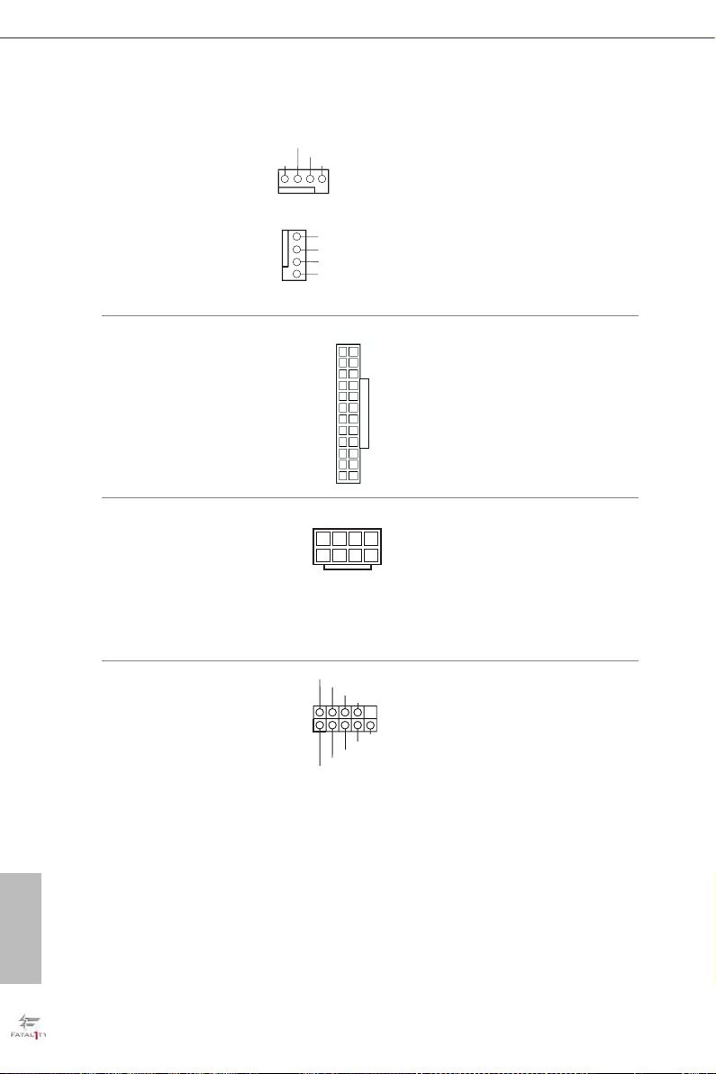
CPU Fan Connectors
14
58
(4-pin CPU_FAN1)
(see p.7, No. 4)
(4-pin CPU_FAN2)
(see p.7, No. 9)
FAN_VOLTAGE
CPU_FAN_SPEED
GND
1 2 3 4
1
2
3
4
FAN_SPEED_CONTROL
GND
FAN_VOLTAGE
CPU_FAN_SPEED
FAN_SPEED_CONTROL
is motherboard pro-
vides two 4-Pin CPU fan
(Quiet Fan) connectors.
If you plan to connect a
3-Pin CPU fan, please
connect it to Pin 1-3.
ATX Power Connector
(24-p i n ATX PWR1)
(see p.7, No. 5)
ATX 12V Power
Connector
(8-pin ATX12V1)
(see p.7, No. 1)
Serial Port Header
(9-p in CO M1)
(see p.7, No. 21)
1
1
12
RRXD1
DDCD#1
DDTR#1
DDSR#1
GND
TTXD1
13
24
CCTS#1
RRI#1
RRTS#1
is motherboard pro-
vides a 24-pin ATX power
connector. To use a 20-pin
ATX power supply, please
plug it along Pin 1 and Pin
13.
is motherboard pro-
vides an 8-pin ATX 12V
power connector. To use a
4-pin ATX power supply,
please plug it along Pin 1
and Pin 5.
is COM1 header
supports a serial port
module.
English
22 23

Fatal1ty E3V5 Performance Gaming/OC Series
TPM Header
(17-pi n TP MS1)
(see p.7, No. 20)
PCIe Power Connector
(4-p i n PC IE _ PWR1)
(see p.7, No. 23)
GN D
LAD 0
+3V S B
D
GN
GN D
SER IRQ #
S_P WRD WN #
GND
+12V DETECT
is connector supports Trusted
Platform Module (TPM) system,
PC ICL K
LAD 3
+3 V
PC IRS T #
FRA M E
which can securely store keys,
1
digital certicates, passwords,
GN D
LAD 1
LAD 2
SMB _CL K_M AIN
SMB _DA TA_ MAI N
and data. A TPM system also
helps enhance network security,
protects digital identities, and
ensures platform integrity.
Please connect a 4 pin molex
power cable to this connector
when more than three graphics
cards are installed.
English

2.7 CrossFireXTM and Quad CrossFireXTM Operation Guide
is motherboard supports CrossFireXTM and Quad CrossFireXTM that allows you
to install up to three identical PCI Express x16 graphics cards.
1. You should only use identical CrossFireXTM-ready g raphics cards that are AM D certied.
2. Make sure that your g raphics card driver supports AMD CrossFireXTM technology.
Download the drivers from the A MD’s website: www.amd.com
3. Ma ke sure th at your power supply unit (PSU) c an provide at least the minimum power
your system requires. It is recommended to use a AMD certied PSU. Ple ase refer to the
AMD’s website for details.
4. If you pair a 12-pipe CrossFireXTM Edition card with a 16-pipe card, both cards will operate as 12-pipe card s while in CrossFireXTM mode.
5. Dierent CrossFireXTM cards may require dierent method s to enable CrossFireXTM.
Please refer to A MD graphics card manuals for de tailed installation guide.
2.7.1 Installing Two CrossFireXTM-Ready Graphics Cards
Step 1
Insert one graphics card into PCIE2 slot
and the other graphics card to PCIE4 slot.
Make sure that the cards are properly
seated on the slots.
Step 2
Connect two graphics cards by installing
a CrossFire Bridge on the CrossFire Bridge
CrossFire Bridge
Interconnects on the top of the graphics
cards. (e CrossFire Bridge is provided
with the graphics card you purchase, not
English
bundled with this motherboard. Please
refer to your graphics card vendor for
deta ils .)
24 25

Fatal1ty E3V5 Performance Gaming/OC Series
Step 3
Connect a VGA cable or a DVI cable to the
monitor connector or the DVI connec-
tor of the graphics card that is inserted to
PCIE2 slot.
English

2.7.2 Driver Installation and Setup
Step 1
Power on your computer and boot into OS.
Step 2
Remove the AMD drivers if you have any VGA drivers installed in your system.
e Catalyst Unins talle r is an optional download. We recommend using this utility to uninstall any previously installed Catalyst drivers prior to installation. Plea se check AMD’s
website for AMD driver updates .
Step 3
Install the required drivers and CATALYST Control Center then restart your
computer. Please check AMD’s website for details.
Step 4
Double-click the AMD Catalyst Control
AMD Catalyst Control Center
Center icon in the Windows® sy stem tray.
Step 5
In the le pane, click Performance and
then AMD CrossFireXTM. en select
Enable AMD CrossFireX and click Apply.
Select the GPU number according to your
graphics card and click Apply.
English
26 27

Fatal1ty E3V5 Performance Gaming/OC Series
Chapter 3 Software and Utilities Operation
3.1 Installing Drivers
e Support CD that comes with the motherboard contains necessary drivers and
useful utilities that enhance the motherboard’s features.
Running The Support CD
To begin using the support CD, insert the CD into your CD-ROM drive. e CD
automatically displays the Main Menu if “AUTORUN” is enabled in your computer.
If the Main Menu does not appear automatically, locate and double click on the le
“ASRSETUP.EXE” in the Support CD to display the menu.
Drivers Menu
e drivers compatible to your system will be auto-detected and listed on the
support CD driver page. Please click Install All or follow the order from top to
bottom to install those required drivers. erefore, the drivers you install can work
properly.
Utilities Menu
e Utilities Menu shows the application soware that the motherboard supports.
Click on a specic item then follow the installation wizard to insta ll it.
To improve Windows 7 compatibility, please download and install the following hot x
provided by Microso.
“KB2720599”: http://support.microso.com/kb/2720599/en-us
English

3.2 F-Stream
F-Stream is ASRock’s multi purpose soware suite with a new interface, more new
features and improved utilities.
3.2.1 Installing F-Stream
F-Stream can be downloaded from ASRock Live Update & APP Shop. Aer the
installation, you will nd the icon “F-Stream“ on your desktop. Double-click the “F-
Stream“ icon, F-Stream main menu will pop up.
3.2.2 Using F-Stream
ere are six sections in F-Stream main menu: Operation Mode, OC Tweaker,
System Info, FAN-Tastic Tuning, Tech Service and Settings.
Operation Mode
Choose an operation mode for your computer.
English
28 29

Fatal1ty E3V5 Performance Gaming/OC Series
OC Tw eaker
Congurations for overclocking the system.
System Info
View information about the system.
*e System Browser tab may not appear for certain models.
English

FAN-Tastic Tuning
Congure up to ve dierent fan speeds using the graph. e fans will automatically shi
to the next speed level when the assigned temperature is met.
Tech Ser vice
Contact Tech Service if you have problems with your computer. Please leave your
contact information along with details of the problem.
English
30 31

Fatal1ty E3V5 Performance Gaming/OC Series
Settings
Congure ASRock F-Stream. Click to select "Auto run at Windows Startup" if you
want F-Stream to be launched when you start up the Windows operating system.
English
3.3 ASRock Live Update & APP Shop
e ASRock Live Update & APP Shop is an online store for purchasing and
downloading soware applications for your ASRock computer. You can quick ly and
easily insta ll various apps and support utilities, such as USB Key, XFast LAN, XFast
RAM and more. With ASRock APP Shop, you can optimize your system and keep
your motherboard up to date simply with a few clicks.
Double-click on your desktop to access ASRock Live Update & APP Shop
utility.
*You need to be connected to the Internet to download apps f rom the ASRock Live Update & APP Shop.
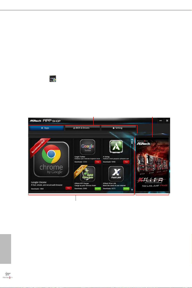
3.3.1 UI Overview
English
Category Panel
Information Panel
Category Panel: e category panel contains several category tabs or buttons that
when selected the information panel below displays the relative information.
Information Panel: e information panel in the center displays data about the
currently selected category and allows users to perform job-related tasks.
Hot News: e hot news section displays the various latest news. Click on the image
to visit the website of the selected news and know more.
Hot News
32 33

Fatal1ty E3V5 Performance Gaming/OC Series
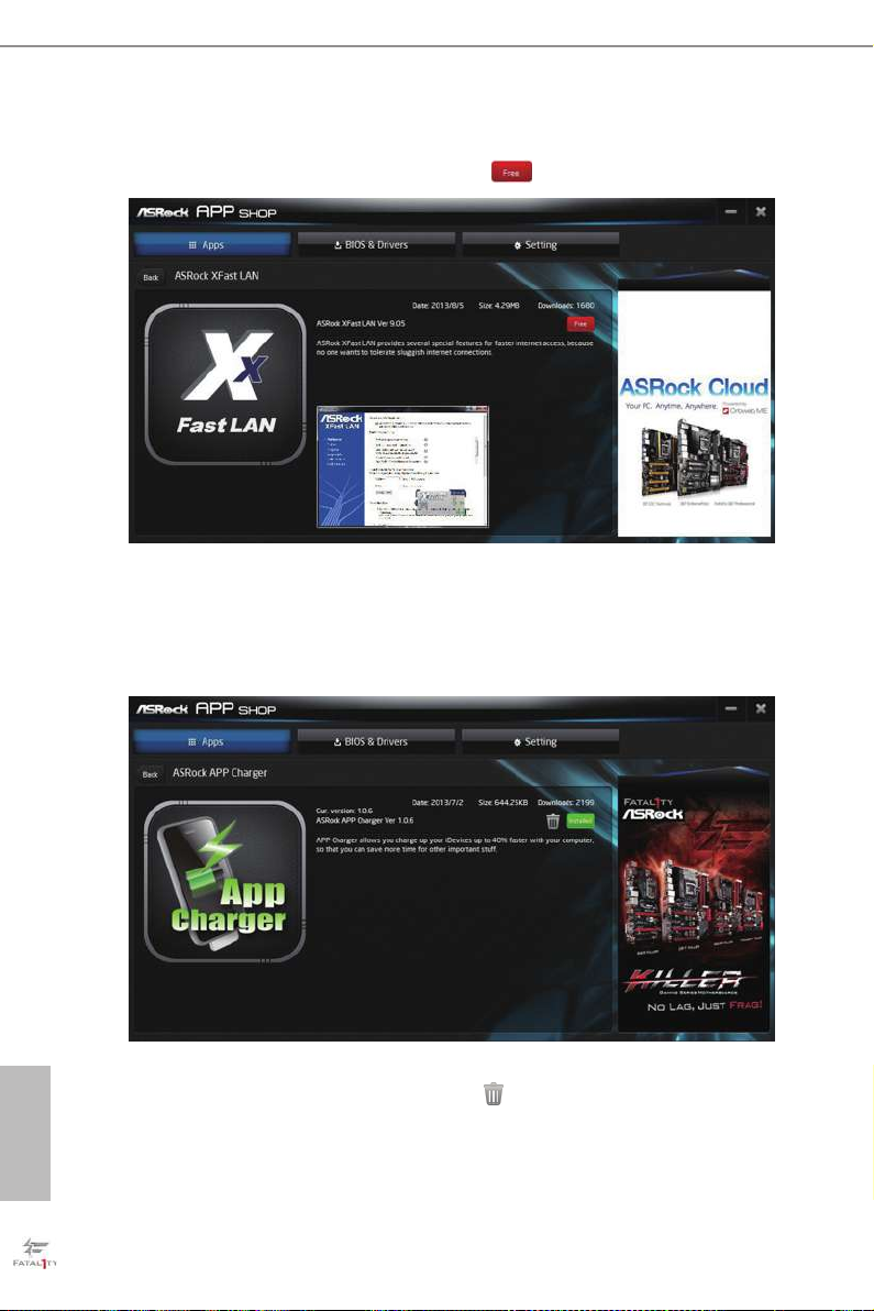
3.3.2 Apps
When the "Apps" tab is selected, you will see all the available apps on screen for you
to download.
Installing an App
Step 1
Find the app you want to install.
e most recommended app appears on the le side of the screen. e other various
apps are shown on the right. Please scroll up and down to see more apps listed.
You can check the price of the app and whether you have already intalled it or not.
- e red icon displays the price or "Free" if the app is free of charge.
- e green "Installed" icon means the app is installed on your computer.
Step 2
Click on the app icon to see more details about the selected app.
English
Step 3
If you want to install the app, click on the red icon
Step 4
When installation completes, you can nd the green "Installed" icon appears on the
upper right corner.
to start downloading.
English
To uninstall it, simply click on the trash can icon .
* e trash icon may not appear for certain apps.
34 35

Fatal1ty E3V5 Performance Gaming/OC Series
Upgrading an App
You can only upgrade the apps you have already installed. When there is an
available new version for your app, you will nd the mark of "New Version"
appears below the installed app icon.
Step 1
Click on the app icon to see more details.
Step 2
Click on the yellow icon
to start upgrading.
English

3.3.3 BIOS & Drivers
Installing BIOS or Drivers
When the "BIOS & Drivers" tab is selected, you will see a list of recommended or
critical updates for the BIOS or drivers. Please update them all soon.
Step 1
Please check the item information before update. Click on
Step 2
Click to select one or more items you want to update.
Step 3
Click Update to start the update process.
to see more details.
English
36 37

Fatal1ty E3V5 Performance Gaming/OC Series
3.3.4 Setting
In the "Setting" page, you can change the language, select the server location, and
determine if you want to automatically run the ASRock Live Update & APP Shop
on Windows startup.
English
3.4 XSplit Broadcaster
XSplit Broadcaster is a desktop application designed to make your multimedia
broadcasting, live-streaming and recording a lot easier and more fun to do, we are
giving away the 3 months premium license which is worth US$24.95 for free!
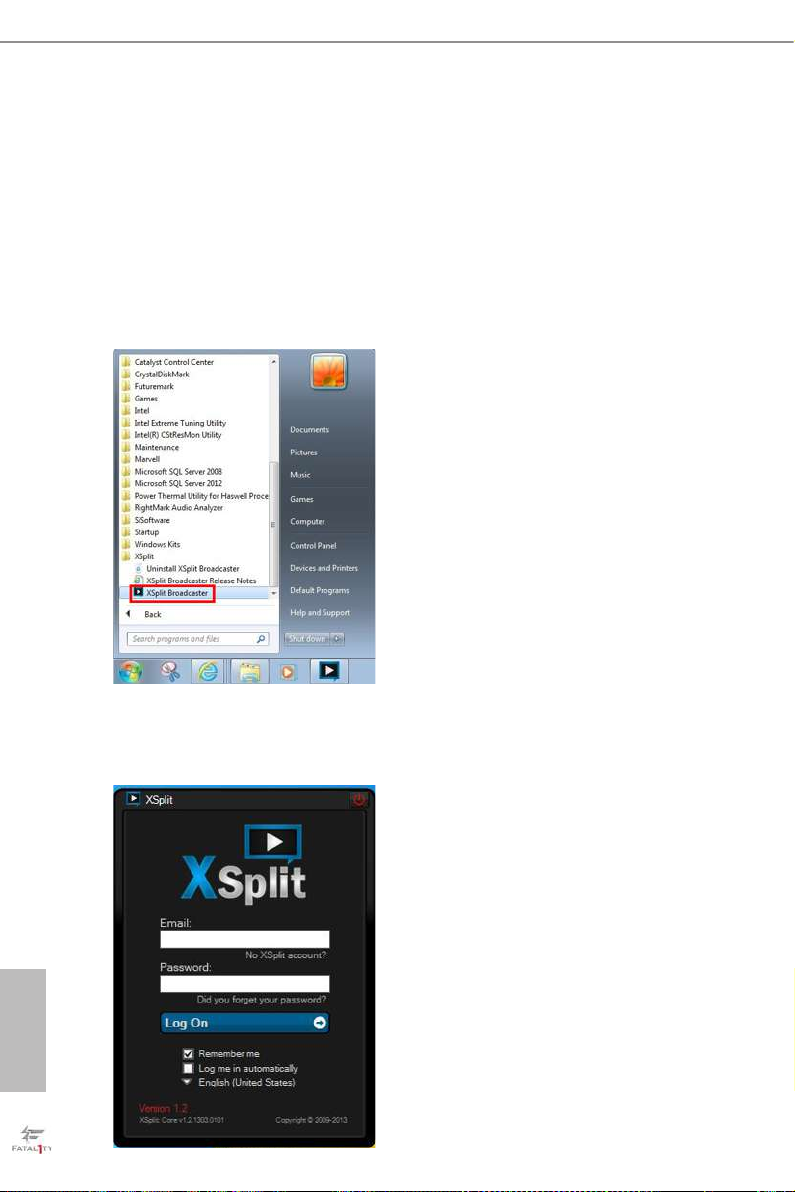
3.4.1 Live Streaming Your Gameplay
Step 1
Go to Start > All Programs > XSplit > XSplit Broadcaster to launch it.
Step 2
Log in with your own username and password. (If you do not have an XSplit
account, click No XSplit account? to regi ster.)
English
38 39
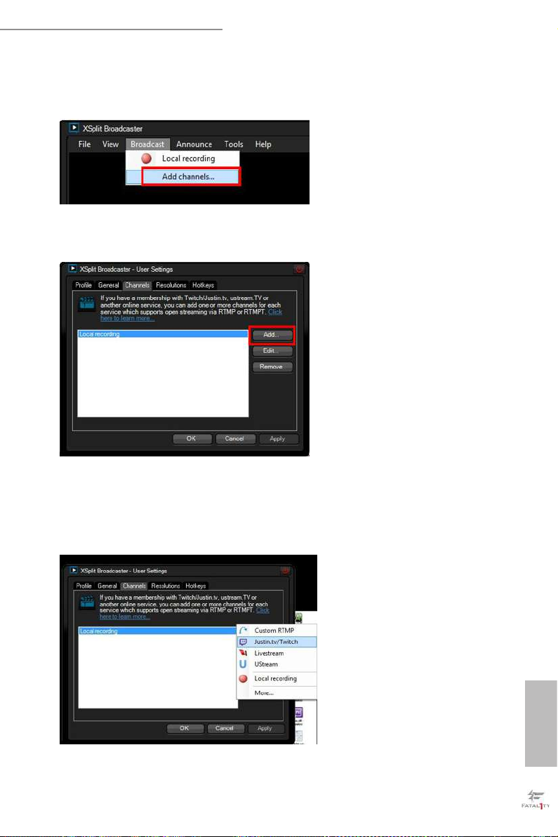
Step 3
Go to Broadcast > Add Channels….
Step 4
Click Add....
Fatal1ty E3V5 Performance Gaming/OC Series
Step 5
Select a platform for live streaming.
*Before you start streaming, you need to register an account for the streaming
service website, such as Twitch.tv, USTREAM, or other livestreaming services.
English

Step 6
Fill in your platform's Username and Password.
Based on your needs, congure the Video and Audio Encoding settings. Click OK.
Step 7
e channel then appears in your broadcast list. Click Apply and OK to save the
settings.
English
40 41
Fatal1ty E3V5 Performance Gaming/OC Series
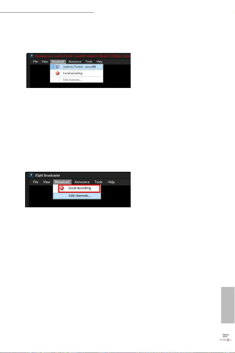
Step 8
Go to Broadcast and select the platform to enable live streaming.
A link to view your live Broadcast has been copied for you automatically. Simply
press CTRL-V or right click and choose Paste to paste the link into the browser, and
you can see your broadcast.
To disable live streaming, go to Broadcast again and deselect the platform.
3.5.2 Recording Your Gameplay
Step 1
Go to Broadcast > Local recording to start recording.
Step 2
To stop recording, Go to Broadcast again and deselect Local recording.
Step 3
Go to Tools > My Recordings...to access your recordings
English

3.5 Enabling USB Ports for Windows® 7 Installation
Intel® Braswell and Skylake has removed their support for the Enhanced Host
Controller Interface (EHCI – USB2.0) and only kept the eXtensible Host Controller
Interface (XHCI – USB3.0). Due to that fact that XHCI is not included in the
Windows 7 inbox drivers, users may nd it dicult to install Windows 7 operating
system because the USB ports on their motherboard won’t work. In order for the
USB ports to function properly, please create a Windows® 7 installation disk with
the Intel® USB 3.0 eXtensible Host Controller (xHCI) drivers packed into the ISO
le.
Requirements
• A Windows® 7 installation disk or USB drive
• USB 3.0 drivers (included in the ASRock Support CD or website)
• A Windows® PC
• Win7 USB Patcher (included in the ASRock Support CD or website)
Scenarios
You have an ODD and PS/2 ports:
If there is an optical disc drive, PS/2 ports and PS/2 Keyboard or mouse on your computer,
you can skip the instructions below and go ahead to install Windows® 7 OS.
You only have an ODD (For Intel Skylake platforms only):
If there is an optical disc drive but no PS/2 ports on your computer, please enable the “PS/2
Simulator” option in UEFI SETUP UTILITY > Advanced > USB Conguration, which
allows the USB port to function as a PS/2 port, and then you can install the Windows® 7
OS. Please set PS/2 Simulator back to disabled aer the installation.
You’ve got nothing:
If you do not have an optical disc drive, please nd another computer and follow the
instructions below to create a new ISO le with the “Win7 USB Patcher”. en use the new
patched Windows® 7 installation USB drive to install Windows® 7 OS.
English
42 43

Fatal1ty E3V5 Performance Gaming/OC Series
Instructions
Step 1
Insert the Windows® 7 installation disk or USB drive to your system.
Step 2
Extract the tool (Win7 USB Patcher) and launch it.
Step 3
Select the “Win7 Folder” from Step1 by clicking the red circle as shown as the picture
below.
Step 4
Select the “USB Driver Folder” by clicking the red circle as shown as the picture below.
If you are using ASRock’s Support CD for the USB 3.0 driver, please select your CD-ROM.
English

Step 5
Select where to save the ISO le by pressing the red circle as shown as the picture below.
Step 6
If you want to burn the patched image to a CD, please check “Burn Image” and select “Target
Device to Burn”. If not, the patched ISO image will be exported to the destination selected
in Step5. en Press “Start” to proceed.
Step 7
Now you are able to install Windows® 7 on Braswell or Skylake with the new burned CD.
Or please use the patched ISO image to make an OS USB drive to install the OS.
English
44 45

Fatal1ty E3V5 Performance Gaming/OC Series
Chapter 4 UEFI SETUP UTILITY
4.1 Introduction
is section explains how to use the UEFI SETUP UTILITY to congure your
system. You may run the UEFI SETUP UTILITY by pressing <F2> or <Del> right
aer you power on the computer, other wise, the Power-On-Self-Test (POST) will
continue with its test routines. If you wish to enter the UEFI SETUP UTILITY aer
POST, restart the system by pressing <Ctl> + <Alt> + <Delete>, or by pressing the
reset button on the system chassis. You may also restart by turning the system o
and then back on.
Becau se the UEFI soware is constantly being upd ated, the following UEFI setup screens
and descriptions are for reference purpose only, and they may not ex actly match what you
see on your screen .
English
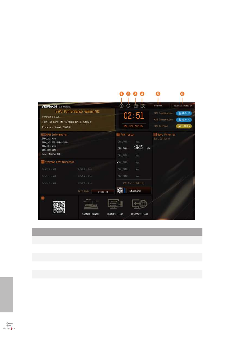
4.2 EZ Mode
e EZ Mode screen appears when you enter the BIOS setup program by default. EZ
mode is a dashboard which contains multiple readings of the system’s current status.
You can check the most crucial information of your system, such as CPU speed,
DRAM frequency, SATA information, fan speed, etc.
Press <F6> or click the "Advanced Mode" button at the upper right corner of the
screen to switch to "Advanced Mode" for more options.
No. Function
Help
1
Load UEFI Defaults
2
Save Changes and Exit
3
Discard Changes
4
Change Language
5
Switch to Advanced Mode
English
6
46 47

Fatal1ty E3V5 Performance Gaming/OC Series
4.3 Advanced Mode
e Advanced Mode provides more options to congure the BIOS settings. Refer to
the following sections for the detailed congurations.
To access the EZ Mode, press <F6> or click the "EZ Mode" button at the upper right
corner of the screen.
4.3.1 UEFI Menu Bar
e top of the screen has a menu bar with the following selections:
Main
OC Tweaker
Advanced
Tool
H/W Monitor
Boot
Security
Exit
For setting system time/date information
For overclocking congurations
For advanced system congurations
Useful tools
Displays current hardware status
For conguring boot settings and boot priority
For security settings
Exit the current screen or the UEFI Setup Utility
English

4.3.2 Navigation Keys
Use < > key or < > key to choose among the selections on the menu bar, and
use < > key or < > key to move the cursor up or down to select items, then
press <Enter> to get into the sub screen. You can also use the mouse to click your
required item.
Please check the following table for the descriptions of each navigation key.
Navigation Key(s) Description
+ / -
<Tab>
<PGUP>
<PGDN>
<HOME>
<END>
<F1>
<F5>
<F7>
<F9>
<F10>
<F12>
<ESC>
To change option for the selected items
Switch to next function
Go to the previous page
Go to the next page
Go to the top of the screen
Go to the bottom of the screen
To display the General Help Screen
Add / Remove Favorite
Discard changes and exit the SETUP UTILITY
Load optimal default values for all the settings
Save changes and exit the SETUP UTILITY
Print screen
Jump to the Exit Screen or exit the current screen
English
48 49

Fatal1ty E3V5 Performance Gaming/OC Series
4.4 Main Screen
When you enter the UEFI SETUP UTILITY, the Main screen will appear and
display the system overview.
Favorite
Display your collection of BIOS items. Press F5 to add/remove your favorite items.
English

4.5 OC Tweaker Screen
In the OC Tweaker screen, you can set up overclocking features.
Becau se the UEFI soware is constantly being upd ated, the following UEFI setup screens
and descriptions are for reference purpose only, and they may not ex actly match what you
see on your screen .
CPU Conguration
BCLK Frequency
e CPU speed is determined by the CPU Ratio multiplied with the BCLK.
Increasing the BCLK will increase the internal CPU clock speed but also aect the
clock speed of other components.
BCLK Step
Congure the BCLK Step Value.
English
BCLK Reset Range
Congure the BCLK Reset Range.
Spread Spectrum
Enable Spread Spectrum to reduce electromagnetic interference for passing EMI
50 51

Fatal1ty E3V5 Performance Gaming/OC Series
tests. Disable to achieve higher clock speeds when overclocking.
CPU Amplitude
Congure the CPU Amplitude.
CPU Slew Rate
Adjust the BCLK signal by dening the maximum change rate of the output voltage.
Higher values will result in a shorter signal rising time.
CPU PLL ORT
Overshoot Reduction Technology improves the BCLK signal to decrease overshoot/
undershoot.
Divider
e default is set to 4 where the max BCLK is 300 MHz, while divider 12 lowers the
max BCLK to 170 MHz, and divider 2 turns it into 300+ MHz.
Boot Performance Mode
Select the performance state that the BIOS will set before OS hando.
FCLK Frequency
Congure the FCLK Frequency.
Intel SpeedStep Technology
Intel SpeedStep technology allows processors to switch between multiple frequen-
cies and voltage points for better power saving and heat dissipation.
Intel Turbo Boost Technology
Intel Turbo Boost Technology enables the processor to run above its base operating
frequency when the operating system requests the highest performance state.
Long Duration Power Limit
Congure Package Power Limit 1 in watts. When the limit is exceeded, the CPU
ratio will be lowered aer a period of time. A lower limit can protect the CPU and
save power, while a higher limit may improve performance.
Long Duration Maintained
Congure the period of time until the CPU ratio is lowered when the Long
Duration Power Limit is exceeded.
English

Short Duration Power Limit
Congure Package Power Limit 2 in watts. When the limit is exceeded, the CPU
ratio will be lowered immediately. A lower limit can protect the CPU and save
power, while a higher limit may improve performance.
DRAM Conguration
DRAM Tweaker
Fine tune the DRAM settings by leaving marks in checkboxes. Click OK to conrm and
apply your new settings.
DRAM Timing Conguration
Load XMP Setting
Load XMP settings to overclock the DDR memory and perform beyond standard
specications.
BCLK Frequency
e CPU speed is determined by the CPU Ratio multiplied with the BCLK. Increasing the
BCLK will increase the internal CPU clock speed but also afect theclock speed of other
components.
DRAM Reference Clock
Select Auto for optimized settings.
DRAM Frequency
If [Auto] is selected, the motherboard will detect the memory module(s) inserted
and assign the appropriate frequency automatically.
Primary Timing
CAS# Latency (tCL)
e time between sending a column address to the memory and the beginning of the data
in response.
RAS# to CAS# Delay and Row Precharge (tRCDtRP) O
English
RAS# to CAS# Delay : e number of clock cycles required between the opening of
a row of memory and accessing columns within it.
Row Precharge: e number of clock cycles required between the issuing of the
precharge command and opening the next row.
52 53

Fatal1ty E3V5 Performance Gaming/OC Series
RAS# Active Time (tRAS)
e number of clock cycles required between a bank active command and issuing the
precharge command.
Command Rate (CR)
e delay between when a memor y chip is selected and when the rst active command can
be issued.
Secondary Timing
Write Recovery Time (tWR)
e amount of delay that must elapse aer the completion of a valid write operation,
before an active bank can be precharged.
Refresh Cycle Time (tRFC)
e number of clocks from a Refresh command until the rst Activate command to
the same rank.
RAS to RAS Delay (tRRD_L)
e number of clocks between two rows activated in dierent banks of the same
rank.
RAS to RAS Delay (tRRD_S)
e number of clocks between two rows activated in dierent banks of the same
rank.
Write to Read Delay (tWTR_L)
e number of clocks between the last valid write operation and the next read command to
the same interna l bank.
Write to Read Delay (tWTR_S)
e number of clocks between the last valid write operation and the next read command to
the same interna l bank.
Read to Precharge (tRTP)
e number of clocks that are inserted between a read command to a row pre-
charge command to the same rank.
Four Activate Window (tFAW)
e time window in which four activates are allowed the same rank.
English

CAS Write Latency (tCWL)
Congure CAS Write Latency.
Third Timing
tREFI
Congure refresh cycles at an average periodic interval.
tCKE
Congure the period of time the DDR4 initiates a minimum of one refresh
command internally once it enters Self-Refresh mode.
tRDRD_sg
Congure between module read to read delay.
tRDRD_dg
Congure between module read to read delay.
tRDRD_dr
Congure between module read to read delay.
tRDRD_dd
Congure between module read to read delay.
tRDWR_sg
Congure between module read to write delay.
tRDWR_dg
Congure between module read to write delay.
tRDWR_dr
Congure between module read to write delay.
tRDWR_dd
Congure between module read to write delay.
English
tWRRD_sg
Congure between module write to read delay.
tWRRD_dg
54 55

Fatal1ty E3V5 Performance Gaming/OC Series
Congure between module write to read delay.
tWRRD_dr
Congure between module write to read delay.
tWRRD_dd
Congure between module write to read delay.
tWRWR_sg
Congure between module write to write delay.
tWRWR_dg
Congure between module write to write delay.
tWRWR_dr
Congure between module write to write delay.
tWRWR_dd
Congure between module write to write delay.
RTL (CH A)
Congure round trip latency for channel A.
RTL (CH B)
Congure round trip latency for channel B.
IO-L (CH A)
Congure IO latency for channel A.
IO-L (CH B)
Congure IO latency for channel B.
Fourth Timing
twRPRE
Congure twR PRE.
Write_Early_ODT
Congure Write_Early_ODT.
English

tAONPD
Congure tAONPD.
tXP
Congure tXP.
tXPDLL
Congure tXPDLL.
tPRPDEN
Congure tPRPDEN.
tRDPDEN
Congure tRDPDEN.
twRPDEN
Congure twR PDEN.
OREF_RI
Congure OREF_RI.
tREFIx9
Congure tR EFIx9.
txSDLL
Congure txSDLL.
txs_oset
Congure txs_oset.
tZQOPER
Congure tZQOPER.
tMOD
Congure tMOD.
English
ZQCS_period
Congure ZQCS_period.
tZQCS
56 57

Fatal1ty E3V5 Performance Gaming/OC Series
Congure tZQCS.
Advanced Setting
ODT WR (CH A)
Congure the memory on die termination resistors' WR for channel A.
ODT WR (CH B)
Congure the memory on die termination resistors' WR for channel B.
ODT PARK (CH A)
Congure the memory on die termination resistors' PARK for channel A.
ODT PARK (CH B)
Congure the memory on die termination resistors' PARK for channel B.
ODT NOM (CH A)
Use this to change ODT (CH A) Auto/Manual settings. e default is [Auto].
ODT NOM (CH B)
Use this to change ODT (CH B) Auto/Manual settings. e default is [Auto].
MRC Fast Boot
Enable Memory Fast Boot to skip DRAM memory training for booting faster.
Voltage Conguration
CPU Vcore Voltage
Congure the voltage for the CPU Vcore.
DRAM Voltage
Use this to congure DRAM Voltage. e default value is [Auto].
DRAM Activating Power Supply
Congure the voltage for the DRAM Activating Power Supply.
PCH +1.0 Voltage
Congure the chipset voltage (1.0V).
VCCIO Voltage
Congure the voltage for the VCCIO.
English

VCC PLL Voltage
Congure the chipset voltage (1.50V).
VCCSA Voltage
Congure the voltage for the VCCSA.
Save User Default
Type a prole name and press enter to save your settings as user default.
Load User Default
Load previously saved user defaults.
English
58 59

Fatal1ty E3V5 Performance Gaming/OC Series
4.6 Advanced Screen
In this section, you may set the congurations for the following items: CPU
Conguration, Chipset Conguration, Storage Conguration, Super IO Congura-
tion, ACPI Conguration, USB Conguration and Trusted Computing.
Setting wrong values in this sec tion may cause the system to malfunction.
UEFI Conguration
Active Page on Entry
Select the default page when entering the UEFI setup utility.
Full HD UEFI
When [Auto] is selected, the resolution will be set to 1920 x 1080 if the monitor
supports Full HD resolution. If the monitor does not support Full HD resolution,
then the resolution will be set to 1024 x 768. When [Disable] is selected, the
resolution will be set to 1024 x 768 directly.
English

4.6.1 CPU Conguration
Intel Hyper Threading Technology
Intel Hyper reading Technology allows multiple threads to run on each core, so
that the overall performance on threaded soware is improved.
Active Processor Cores
Select the number of cores to enable in each processor package.
CPU C States Support
Enable CPU C States Support for power saving. It is recommended to keep C3, C6
and C7 all enabled for better power saving.
Enhanced Halt State (C1E)
Enable Enhanced Halt State (C1E) for lower power consumption.
Package C State Support
Enable CPU, PCIe, Memory, Graphics C State Support for power saving.
English
CPU Thermal Throttling
Enable CPU internal thermal control mechanisms to keep the CPU from overheat-
ing.
60 61

Fatal1ty E3V5 Performance Gaming/OC Series
No-Execute Memory Protection
Processors with No-Execution Memory Protection Technology may prevent certain
classes of malicious buer overow attacks.
Intel Virtualization Technology
Intel Virtualization Technology allows a platform to run multiple operating systems
and applications in independent partitions, so that one computer system can
function as multiple virtual systems.
Hardware Prefetcher
Automatically prefetch data and code for the processor. Enable for better
performance.
Adjacent Cache Line Prefetch
Automatically prefetch the subsequent cache line while retrieving the currently
requested cache line. Enable for better performance.
English

4.6.2 Chipset Conguration
Top of Lower Usable DRAM
Set the maximum value of TOLUD. Set this item to Dynamic to allow TOLUD to
adjust automatically based on the largest MMIO length of the installed graphic
cont roller.
VT-d
Intel® Virtualization Technology for Directed I/O helps your virtual machine
monitor better utilize hardware by improving application compatibility and
reliability, and providing additional levels of manageability, security, isolation, and
I/O performance.
PCIE2 Link Speed
Select the link speed for PCIE2.
PCIE ASPM Support
is option enables/disables the ASPM support for all CPU downstream devices.
English
PCH PCIE ASPM Support
is option enables/disables the ASPM support for all PCH PCIE devices.
62 63

Fatal1ty E3V5 Performance Gaming/OC Series
DMI ASPM Support
is option enables/disables the control of ASPM on CPU side of the DMI Link.
PCH DMI ASPM Support
is option enables/disables the ASPM support for all PCH DMI devices.
Onboard LAN
Enable or disable the onboard network interface controller.
Onboard HD Audio
Enable/disable onboard HD audio. Set to Auto to enable onboard HD audio and
automatically disable it when a sound card is installed.
Front Panel
Enable/disable front panel HD audio.
Deep Sleep
Congure deep sleep mode for power saving when the computer is shut down.
Restore on AC/Power Loss
Select the power state aer a power failure. If [Power O] is selected, the power will
remain o when the power recovers. If [Power On] is selected, the system will start
to boot up when the power recovers.
Good Night LED
By enabling Good Night LED, the Power/HDD LEDs will be switched o when the
system is on. It will also automatically switch o the Power and Keyboard LEDs
when the system enters into Standby/Hibernation mode.
English

4.6.3 Storage Conguration
SATA Controller(s)
Enable/disable the SATA controllers.
SATA Mode Selection
IDE: For better compatibility
AHCI: Supports new features that improve performance.
AHCI (Advanc ed Host Controll er Inter face) support s NCQ and other new features that will
improve SATA disk performance but IDE mode does not have these advantage s.
SATA Aggressive Link Power Management
SATA Aggressive Link Power Management allows SATA devices to enter a low
power state during periods of inactivity to save power. It is only supported by AHCI
mode.
English
Hard Disk S.M.A.R.T.
S.M.A.R.T stands for Self-Monitoring, Analysis, and Reporting Technolog y. It is a
monitoring system for computer hard disk drives to detect and report on various
indicators of reliability.
64 65

Fatal1ty E3V5 Performance Gaming/OC Series
4.6.4 Super IO Conguration
Serial Port
Enable or disable the Serial port.
Serial Port Address
Select the address of the Serial port.
PS2 Y- Cable
Enable the PS2 Y-Cable or set this option to Auto.
English
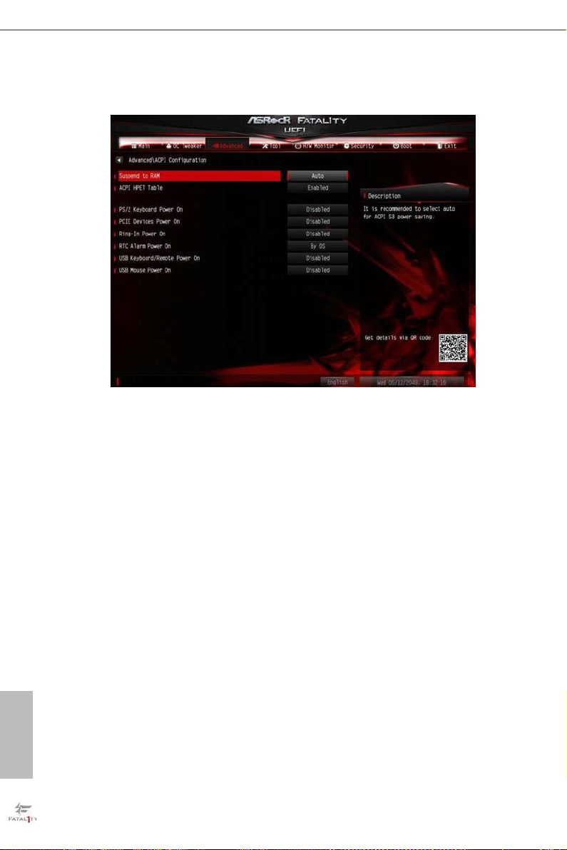
4.6.5 ACPI Conguration
Suspend to RAM
Select disable for ACPI suspend type S1. It is recommended to select auto for ACPI
S3 power saving.
ACPI HEPT Table
Enable the High Precision Event Timer for better performance.
PS/2 Keyboard Power On
Allow the system to be waked up by a PS/2 Keyboard.
PCIE Devices Power On
Allow the system to be waked up by a PCIE device and enable wake on LAN.
Ring-In Power On
Allow the system to be waked up by onboard COM port modem Ring-In signals.
RTC Alarm Power On
English
Allow the system to be waked up by the rea l time clock alarm. Set it to By OS to let
it be handled by your operating system.
66 67

Fatal1ty E3V5 Performance Gaming/OC Series
USB Keyboard/Remote Power On
Allow the system to be waked up by an USB keyboard or remote controller.
USB Mouse Power On
Allow the system to be waked up by an USB mouse.
English

4.6.6 USB Conguration
Legacy USB Support
Enable or disable Legacy OS Support for USB 2.0 devices. If you encounter USB
compatibility issues it is recommended to disable legacy USB support. Select UEFI
Setup Only to support USB devices under the UEFI setup and Windows/Linux
operating systems only.
PS/2 Simulator
Enable this item for the complete USB keyboard legacy support for non-USB aware
operating system.
English
68 69
Fatal1ty E3V5 Performance Gaming/OC Series
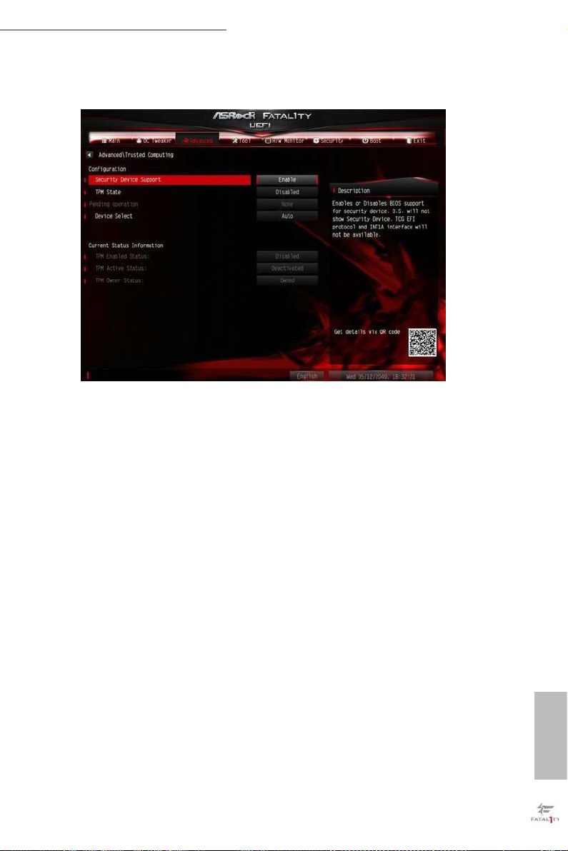
4.6.7 Trusted Computing
Security Device Support
Enable or disable BIOS support for security device.
English

4.7 Tools
System Browser
ASRock System Browser shows the overview of your current PC and the devices
connected.
OMG (Online Management Guard)
Administrators are able to establish an internet curfew or restrict internet access
at specied times via OMG. You may schedule the starting and ending hours of
internet access granted to other users. In order to prevent users from bypassing
OMG, guest accounts without permission to modify the system time are required.
UEFI Tech Service
Easy R AID Installer helps you to copy the R AID driver from the support CD to
your USB storage device. Aer copying the drivers please change the SATA mode to
RAID, then you can start installing the operating system in RAID mode.
Easy RAID Installer
English
Contact ASRock Tech Service if you are having trouble with your PC. Please setup
network conguration before using UEFI Tech Service.
70 71

Fatal1ty E3V5 Performance Gaming/OC Series
Easy Driver Installer
For users that don’t have an optical disk drive to install the drivers from our support
CD, Easy Driver Installer is a handy tool in the UEFI that installs the LAN driver
to your system via an USB storage device, then downloads and installs the other
required drivers automatically.
Boot Manager
Boot Manager is specically designed for the dual OS platform/multi-OS platform
users to easily customize and manage the boot menu.
*Please connect more than one boot devices to use this tool.
Boot Manager
Enable/disable the Boot Manager.
Boot Manager Timeout
Enable/disable the Boot Manager Timeout.
Timeout Seconds
Congure the number of seconds to wait for the Boot Manager.
Instant Flash
Save UEFI les in your USB storage device and run Instant Flash to update your
UEFI.
English

Internet Flash - DHCP (Auto IP), Auto
ASRock Internet Flash downloads and updates the latest UEFI rmware version
from our servers for you. Please setup network conguration before using Internet
Flash.
*For BIOS backup and recovery purpose, it is recommended to plug in your USB
pen drive before using this function.
Network Conguration
Use this to congure internet connection settings for Internet Flash.
Internet Setting
Enable or disable sound eects in the setup utility.
UEFI Download Server
Select a server to download the UEFI rmware.
English
72 73

Fatal1ty E3V5 Performance Gaming/OC Series
4.8 Hardware Health Event Monitoring Screen
is section allows you to monitor the status of the hardware on your system,
including the parameters of the CPU temperature, motherboard temperature, fan
speed and voltage.
Fan-Tastic Tuning
Select a fan mode for CPU Fans 1&2, or choose Customize to set 5 CPU
temperatures and assign a respective fan speed for each temperature.
CPU Fan 1 Setting
Select a fan mode for CPU Fans 1, or choose Customize to set 5 CPU temperatures
and assign a respective fan speed for each temperature.
CPU Fan 2 Setting
Select a fan mode for CPU Fans 2, or choose Customize to set 5 CPU temperatures
and assign a respective fan speed for each temperature.
Chassis Fan 1 Setting
Select a fan mode for Chassis Fan 1, or choose Customize to set 5 CPU temperatures
and assign a respective fan speed for each temperature.
Chassis Fan 1 Temp Source
Select a fan temperature source for Chassis Fan 1.
English

Chassis Fan 2 Setting
Select a fan mode for Chassis Fan 2, or choose Customize to set 5 CPU temperatures
and assign a respective fan speed for each temperature.
Chassis Fan 2 Temp Source
Select a fan temperature source for Chassis Fan 2.
Chassis Fan 3 Setting
Select a fan mode for Chassis Fan 3, or choose Customize to set 5 CPU temperatures
and assign a respective fan speed for each temperature.
Chassis Fan 3 Temp Source
Select a fan temperature source for Chassis Fan 3.
Chassis Fan 4 Setting
Select a fan mode for Chassis Fan 4, or choose Customize to set 5 CPU temperatures
and assign a respective fan speed for each temperature.
Chassis Fan 4 Temp Source
Select a fan temperature source for Chassis Fan 4.
English
74 75

Fatal1ty E3V5 Performance Gaming/OC Series
4.9 Security Screen
In this section you may set or change the supervisor/user password for the system.
You may also clear the user password.
Supervisor Password
Set or change the password for the administrator account. Only the administrator
has authority to change the settings in the UEFI Setup Utility. Leave it blank and
press enter to remove the password.
User Password
Set or change the password for the user account. Users are unable to change the
settings in the UEFI Setup Utility. Leave it blank and press enter to remove the
password.
Secure Boot
Use this item to enable or disable support for Windows 8.1 Secure Boot.
English

4.10 Boot Screen
is section displays the available devices on your system for you to congure the
boot settings and the boot priority.
Fast Boot
Fast Boot minimizes your computer's boot time. In fast mode you may not boot
from an USB storage device. Ultra Fast mode is only supported by Windows 8.1
and the VBIOS must support UEFI GOP if you are using an external graphics card.
Please notice that Ultra Fast mode will boot so fast that the only way to enter this
UEFI Setup Utility is to Clear CMOS or run the Restart to UEFI utility in Windows.
Boot From Onboard LAN
Allow the system to be waked up by the onboard LAN.
Setup Prompt Timeout
Congure the number of seconds to wait for the setup hot key.
Bootup Num-Lock
Select whether Num Lock should be turned on or o when the system boots up.
English
Boot Beep
Select whether the Boot Beep should be turned on or o when the system boots up. Please
note that a buzzer is needed.
76 77

Fatal1ty E3V5 Performance Gaming/OC Series
Full Screen Logo
Enable to display the boot logo or disable to show normal POST messages.
AddOn ROM Display
Enable AddOn ROM Display to see the AddOn ROM messages or congure the
AddOn ROM if you've enabled Full Screen Logo. Disable for faster boot speed.
Boot Failure Guard
If the computer fails to boot for a number of times the system automatically restores
the default settings.
Boot Failure Guard Count
Congure the number of attempts to boot until the system automatically restores
the default settings.
English

CSM (Compatibility Support Module)
CSM
Enable to launch the Compatibility Support Module. Please do not disable unless
you’re running a WHCK test. If you are using Windows 8.1 64-bit and all of your
devices support UEFI, you may also disable CSM for faster boot speed.
Launch PXE OpROM Policy
Select UEFI only to run those that support UEFI option ROM only. Select Legacy
only to run those that support legacy option ROM only. Select Do not launch to not
execute both legacy and UEFI option ROM.
Launch Storage OpROM Policy
Select UEFI only to run those that support UEFI option ROM only. Select Legacy
only to run those that support legacy option ROM only. Select Do not launch to not
execute both legacy and UEFI option ROM.
Launch Video OpROM Policy
English
Select UEFI only to run those that support UEFI option ROM only. Select Legacy
only to run those that support legacy option ROM only. Select Do not launch to not
execute both legacy and UEFI option ROM.
78 79
Fatal1ty E3V5 Performance Gaming/OC Series
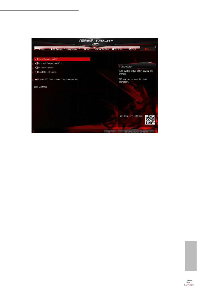
4.11 Exit Screen
Save Changes and Exit
When you select this option the following message, “Save conguration changes
and exit setup?” will pop out. Select [OK] to save changes and exit the UEFI SETUP
UTILITY.
Discard Changes and Exit
When you select this option the following message, “Discard changes and exit
setup?” will pop out. Select [OK] to exit the UEFI SETUP UTILITY without saving
any changes.
Discard Changes
When you select this option the following message, “Discard changes?” will pop
out. Select [OK] to discard all changes.
Load UEFI Defaults
Load UEFI default values for a ll options. e F9 key can be used for this operation.
Launch EFI Shell from lesystem device
Copy shellx64.e to the root directory to launch EFI Shell.
English

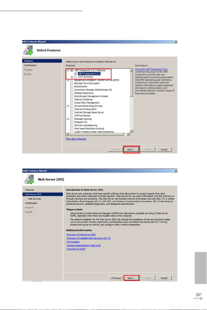
Chapter 5: Net Framework Installation Guide
To let Intel® RSTe works properly, it is required to install Net Framework. Please follow the
steps below to enable “.Net Framework” feature on Microso® Windows® Server 2008 R2.
5.1 Installing .Net Framework 3.5.1 (For Server 2008 R2)
1. Double-click the Server Manager icon in the Windows system tray.
2. Click Add Features in the right hand pane.
English
80 81
Fatal1ty E3V5 Performance Gaming/OC Series
3. Check the box next to .Net Framework 3.5.1 and then click Next.
4. Click Next to continue.
English

5. Click Install to start installing .Net Framework 3.5.1.
6. Aer the installation completes, click Close.
English
82 83

Contact Information
If you need to contact ASRock or want to know more about ASRock, you’re welcome
to visit ASRock’s website at http://ww w.asrock.com; or you may contact your dealer
for further information. For technical questions, please submit a support request
form at http://www.asrock.com/support/tsd.asp
ASRock Incorporation
2F., No.37, Sec. 2, Jhongyang S. Rd., Beitou District,
Taipei City 112, Taiwan (R.O.C.)
ASRock EUROPE B.V.
Bijsterhuizen 11-11
6546 AR Nijmegen
e Netherlands
Phone: +31-24-345-44-33
Fax: +31-24-345-44-38
ASRock America, Inc.
13848 Magnolia Ave, Chino, CA91710
U.S.A.
Phone: +1-909-590-8308
Fax: +1-909-590-1026
 Loading...