

Page 1

Page 2

Version 1.0
Published October 2016
Copyright©2016 ASRock INC. All rights reserved.
Copyright Notice:
No part of this documentation may be reproduced, transcribed, transmitted, or
translated in any language, in any form or by any means, except duplication of
documentation by the purchaser for backup purpose, without written consent of
ASRock Inc.
Products and corporate names appearing in this documentation may or may not
be registered trademarks or copyrights of their respective companies, and are used
only for identication or explanation and to the owners’ benet, without intent to
infringe.
Disclaimer:
Specications and information contained in this documentation are furnished for
informational use only and subject to change without notice, and should not be
constructed as a commitment by ASRock. ASRock assumes no responsibility for
any errors or omissions that may appear in this documentation.
With respect to the contents of this documentation, ASRock does not provide
warranty of any kind, either expressed or implied, including but not limited to
the implied warranties or conditions of merchantability or tness for a particular
purpose.
In no event shall ASRock, its directors, ocers, employees, or agents be liable for
any indirect, special, incidental, or consequential damages (including damages for
loss of prots, loss of business, loss of data, interruption of business and the like),
even if ASRock has been advised of the possibility of such damages arising from any
defect or error in the documentation or product.
is device complies with Part 15 of the FCC Rules. Operation is subject to the following
two conditions:
(1) this device may not cause harmful interference, and
(2) this device must accept any interference received, including interference that
may cause undesired operation.
CALIFORNIA, USA ONLY
e Lithium battery adopted on this motherboard contains Perchlorate, a toxic substance
controlled in Perchlorate Best Management Practices (BMP) regulations passed by the
California Legislature. When you discard the Lithium battery in California, USA, please
follow the related regulations in advance.
“Perchlorate Material-special handling may apply, see ww w.dtsc.ca.gov/hazardouswaste/
perchlorate”
ASRock Website: http://www.asrock.com
Page 3

AUSTRALIA ONLY
Our goods come with guarantees that cannot be excluded under the Australian Consumer
Law. You are entitled to a replacement or refund for a major failure and compensation for
any other reasonably foreseeable loss or damage caused by our goods. You are also entitled
to have the goods repaired or replaced if the goods fail to be of acceptable quality and the
failure does not amount to a major failure. If you require assistance please call ASRock Tel
: +886-2-28965588 ext.123 (Standard International call charges apply)
e terms HDMI™ and HDMI High-Denition Multimedia Interface, and the HDMI
logo are trademarks or registered trademarks of HDMI Licensing LLC in the United
States and other countries.
Page 4

Fatal1ty Story
Who knew that at age 19, I would be a World Champion PC gamer. When I was 13, I actually
played competitive billiards in professional tournaments and won four or ve games o guys
who played at the highest level. I actually thought of making a career of it, but at that young
age situations change rapidly. Because I’ve been blessed with great hand-eye coordination and
a grasp of mathematics (an important element in video gaming) I gravitated to that activity.
GOING PRO
I started professional gaming in 1999 when I entered the CPL (Cyberathlete Professional
League) tournament in Dallas and won $4,000 for coming in third place. Emerging as one
of the top players in the United States, a company interested in sponsoring me ew me to
Sweden to compete against the top 12 players in the world. I won 18 straight games, lost
none, and took rst place, becoming the number one ranked Quake III player in the world
in the process. Two months later I followed that success by traveling to Dallas and defending
my title as the world’s best Quake III player, winning the $40,000 grand prize. From there
I entered competitions all over the world, including Singapore, Korea, Germany, Australia,
Holland and Brazil in addition to Los Angeles, New York and St. Louis.
WINNING STREAK
I was excited to showcase my true gaming skills when defending my title as CPL
Champion of the year at the CPL Winter 2001 because I would be competing in a totally
dierent rst person shooter (fps) game, Alien vs. Predator II. I won that competition and
walked away with a new car. e next year I won the same title playing Unreal Tournament
2003, becoming the only three-time CPL champion of the year. And I did it playing a
different game each year, something no one else has ever done and a feat of which I am
extremely proud.
At QuakeCon 2002, I faced o against my rival ZeRo4 in one of the most highly
anticipated matches of the year, winning in a 14 to (-1) killer victory. Competing at Quakecon
2004, I became the World’s 1st Doom3 Champion by defeating Daler in a series of very
challenging matches and earning $25,000 for the victory.
Since then Fatal1ty has traveled the globe to compete against the best in the world, winning
prizes and acclaim, including the 2005 CPL World Tour Championship in New York City for
a $150,000 rst place triumph. In August 2007, Johnathan was awarded the rst ever Lifetime
Achievement Award in the four year history of the eSports-Award for “showing exceptional
sportsmanship, taking part in shaping eSports into what it is today and for being the prime
representative of this young sport. He has become the gurehead for eSports worldwide”.
Page 5

LIVIN’ LARGE
Since my rst big tournament wins, I have been a “Professional Cyberathlete”, traveling the
world and livin’ large with lots of International media coverage on outlets such as MTV,
ESPN and a 60 Minutes segment on CBS to name only a few. It's unreal - it's crazy. I’m living
a dream by playing video games for a living. I’ve always been athletic and took sports like
hockey and football very seriously, working out and training hard. is discipline helps me
become a better gamer and my drive to be the best has opened the doors necessary to become
a professional.
A DREAM
Now, another dream is being realized – building the ultimate gaming computer, made
up of the best parts under my own brand. Quality hardware makes a huge difference in
competitions…a couple more frames per second and everything gets really nice. It’s all about
getting the computer processing faster and allowing more uid movement around the maps.
My vision for Fatal1ty hardware is to allow gamers to focus on the game without worrying
about their equipment, something I’ve preached since I began competing. I don’t want to
worry about my equipment. I want to be there – over and done with - so I can focus on
the game. I want it to be the fastest and most stable computer equipment on the face of the
planet, so quality is what Fatal1ty Brand products represent.
Johnathan “Fatal1ty” Wendel
e Fatal1ty name, Fatal1ty logos and the Fatal1ty likeness are registered trademarks of Fatal1ty, Inc., and are used
under license. © 2016 Fatal1ty, Inc. All rights reserved. All other trademarks are the property of their respective
owners.
Page 6

Contents
Chapter 1 Introduction 1
1.1 Package Contents 1
1.2 Specications 2
1.3 Motherboard Layout 7
1.4 I/O Panel 9
Chapter 2 Installation 11
2.1 Installing the CPU 12
2.2 Installing the CPU Fan and Heatsink 15
2.3 Installing Memory Modules (DIMM) 16
2.4 Expansion Slots (PCI Express Slots) 18
2.5 Onboard Headers and Connectors 19
2.6 CrossFireXTM and Quad CrossFireXTM Operation Guide 24
2.6.1 Installing Two CrossFireXTM-Ready Graphics Cards 24
2.6.2 Driver Installation and Setup 26
2.7 M.2_SSD (NGFF) Module Installation Guide 27
Chapter 3 Software and Utilities Operation 30
3.1 Installing Drivers 30
3.2 ASRock Live Update & APP Shop 31
3.2.1 UI Overview 31
3.2.2 Apps 32
3.2.3 BIOS & Drivers 35
3.2.4 Setting 36
Page 7

3.3 Creative SoundBlaster Cinema3 37
3.4 Enabling USB Ports for Windows® 7 Installation 38
Chapter 4 UEFI SETUP UTILITY 41
4.1 Introduction 41
4.2 EZ Mode 42
4.3 Advanced Mode 43
4.3.1 UEFI Menu Bar 43
4.3.2 Navigation Keys 44
4.4 Main Screen 45
4.5 OC Tweaker Screen 46
4.6 Advanced Screen 52
4.6.1 CPU Conguration 53
4.6.2 Chipset Conguration 55
4.6.3 Storage Conguration 58
4.6.4 Super IO Conguration 59
4.6.5 ACPI Conguration 60
4.6.6 USB Conguration 62
4.6.7 Trusted Computing 63
4.7 Tools 64
4.8 Hardware Health Event Monitoring Screen 67
4.9 Security Screen 69
4.10 Boot Screen 70
4.11 Exit Screen 73
Page 8

Fatal1ty B250M Performance Series
Chapter 1 Introduction
ank you for purchasing ASRock Fatal1ty B250M Performance Series
motherboard, a reliable motherboard produced under ASRock’s consistently
stringent quality control. It delivers excellent performance with robust design
conforming to ASRock’s commitment to quality and endurance.
In this documentation, Chapter 1 and 2 contains the introduction of the
motherboard and step-by-step installation guides. Chapter 3 contains the operation
guide of the soware and utilities. Chapter 4 contains the conguration guide of
the BIOS setup.
Becau se the motherboard specications and the BIOS soware might be updated, the
content of this documentation will be subject to change without notice. In case any
modications of this documentation occur, the updated version will be available on
ASRock’s website w ithout f urther notice. If you require technical support relate d to
this motherboard, please vi sit our website for s pecic information about the model
you are using. You may nd the l atest VGA cards and CPU suppor t list on ASRock’s
website a s well. ASRock website ht tp://www.a srock.com.
1.1 Package Contents
ASRock Fatal1ty B250M Performance Series Motherboard (Micro ATX Form Factor)
•
ASRock Fatal1ty B250M Performance Series Quick Installation Guide
•
ASRock Fatal1ty B250M Performance Series Support CD
•
2 x Serial ATA (SATA) Data Cables (Optional)
•
2 x Screws for M.2 Sockets (Optional)
•
1 x I/O Panel Shield
•
English
1
Page 9

1.2 Specications
Platform
CPU
Chipset
Memory
•
•
•
•
•
•
•
•
•
* 7th Gen Intel® CPU supports DDR4 up to 2400; 6th Gen Intel®
CPU supports DDR4 up to 2133.
•
•
•
•
Micro ATX Form Factor
Supports 7th and 6th Generation Intel® CoreTM i7/i5/i3/
Pentium®/Celeron® Processors (Socket 1151)
Digi Power design
6 Power Phase design
Supports Intel® Turbo Boost 2.0 Technology
Intel® B250
Dual Channel DDR4 Memory Technology
4 x DDR4 DIMM Slots
Supports DDR4 2400/2133 non-ECC, un-buered memory*
Supports ECC UDIMM memory modules (operate in non-
ECC mode)
Max. capacity of system memory: 64GB
Supports Intel® Extreme Memory Prole (XMP) 2.0
15μ Gold Contact in DIMM Slots
English
2
Expansion
Slot
Graphics
2 x PCI Express 3.0 x16 Slots (PCIE1: x16 mode; PCIE4: x4
•
mode)*
* Supports NVMe SSD as boot disks
2 x PCI Express 3.0 x1 Slots (Flexible PCIe)
•
Supports AMD Quad CrossFireXTM and CrossFireX
•
15μ Gold Contact in VGA PCIe Slot (PCIE1)
•
Intel® HD Graphics Built-in Visuals and the VGA outputs
•
can be supported only with processors which are GPU
integrated.
Supports Intel® HD Graphics Built-in Visuals : Intel® Quick
•
Sync Video with AVC, MVC (S3D) and MPEG-2 Full
HW Encode1, Intel® InTruTM 3D, Intel® Clear Video HD
Technology, Intel® InsiderTM, Intel® HD Graphics
Gen9 LP, DX11.3, DX12
•
TM
Page 10

Fatal1ty B250M Performance Series
HWAEncode/Decode: VP8, HEVC 8b, VP9, HEVC 10b (For
•
7th Gen Intel® CPU)
HWA Encode/Decode: VP8 , HEVC 8b; GPU/SWEncode/
•
Decode: VP9, HEVC 10b (For 6th Gen Intel® CPU)
Max. shared memory 1024MB
•
* e size of ma ximum shared memory may vary from dierent
operating systems.
ree graphics output options: D-Sub, DVI-D and HDMI
•
Supports Triple Monitor
•
Supports HDMI with max. resolution up to 4K x 2K
•
(4096x2160) @ 24Hz / (3840x2160) @ 30Hz
Supports DVI-D with ma x. resolution up to 1920x1200 @
•
60Hz
Supports D-Sub with max. resolution up to 1920x1200 @
•
60Hz
Supports Auto Lip Sync, Deep Color (12bpc), xvYCC and
•
HBR (High Bit Rate Audio) with HDMI Port (Compliant
HDMI monitor is required)
Supports HDCP with DVI-D and HDMI Ports
•
Supports Full HD 1080p Blu-ray (BD) playback with DVI-D
•
and HDMI Ports
Audio
LAN
7.1 CH HD Audio with Content Protection (Realtek ALC892
•
Audio Codec)
* To congure 7.1 CH HD Audio, it is required to use an HD
front panel audio module and enable the multi-channel audio
feature through the audio driver.
Premium Blu-ray Audio support
•
Supports Surge Protection (ASRock Full Spike Protection)
•
Nichicon Fine Gold Series Audio Caps
•
Supports Creative SoundBlaster Cinema3
•
Gigabit LAN 10/100/1000 Mb/s
•
Giga PHY Intel® I219V
•
Supports Wake-On-LAN
•
Supports Lightning/ESD Protection (ASRock Full Spike
•
Protection)
Supports Energy Ecient Ethernet 802.3az
•
Supports PXE
•
English
3
Page 11

Rear Panel
I/O
Storage
1 x PS/2 Mouse Port
•
1 x PS/2 Keyboard Port
•
1 x D-Sub Port
•
1 x DVI-D Port
•
1 x HDMI Port
•
1 x USB 2.0 Port (Supports ESD Protection (ASRock Full
•
Spike Protection))
1 x Fatal1ty Mouse Port (USB 2.0) (Supports ESD Protection
•
(ASRock Full Spike Protection))
3 x USB 3.0 Type-A Ports (Supports ESD Protection (ASRock
•
Full Spike Protection))
1 x USB 3.0 Type-C Port (Supports ESD Protection (ASRock
•
Full Spike Protection))
1 x RJ-45 LAN Port with LED (ACT/LINK LED and SPEED
•
LED)
HD Audio Jacks: Line in / Front Speaker / Microphone
•
6 x SATA3 6.0 Gb/s Connectors, support NCQ, AHCI and
•
Hot Plug*
* If M2_1 is occupied by a SATA-type M.2 device, SATA3_0 will
be disabled.
1 x Ultra M.2 Socket (M2_1), supports ty pe
•
2230/2242/2260/2280 M.2 SATA3 6.0 Gb/s module and M.2
PCI Express module up to Gen3 x4 (32 Gb/s)**
1 x Ultra M.2 Socket (M2_2), supports type
•
2230/2242/2260/2280 M.2 PCI Express module up to Gen3
x4 (32 Gb/s)**
** If PCIE2 slot or PCIE3 slot is occupied, the PCIe-type M.2
device on M2_1 socket will run at Gen3 x2 (16 Gb/s).
** Supports Intel® OptaneTM Technology (M2 _2 only)
** Supports NVMe SSD as boot disks
** Supports ASRock U.2 Kit
English
4
Connector
1 x Print Port Header
•
1 x COM Port Header
•
1 x TPM Header
•
1 x Chassis Intrusion and Speaker Header
•
1 x AURA RGB LED Header
•
2 x CPU Fan Connectors (1 x 4-pin, 1 x 3-pin)
•
* e CPU Fan Connector supports the CPU fan of ma ximum
1A (12W) fan power.
Page 12

BIOS
Feature
Hardware
Monitor
Fatal1ty B250M Performance Series
2 x Chassis Fan Connectors (4-pin) (Smart Fan Speed Con-
•
trol)
* CHA_FAN1 and CHA _FAN2 can auto detect if 3-pin or 4-pin
fan is in use.
1 x 24 pin ATX Power Connector
•
1 x 8 pin 12V Power Connector
•
1 x Front Panel Audio Connector
•
2 x USB 2.0 Headers (Support 4 USB 2.0 ports) (Supports
•
ESD Protection (ASRock Full Spike Protection))
1 x USB 3.0 Header (Supports 2 USB 3.0 ports) (Supports
•
ESD Protection (ASRock Full Spike Protection))
AMI UEFI Legal BIOS with multilingual GUI support
•
ACPI 6.0 Compliant wake up events
•
SMBIOS 2.7 Support
•
CPU, GT_CPU, DRAM, PCH 1.0V, VCCIO, VCCSA, VCCST
•
Voltage Multi-adjustment
CPU/Chassis temperature sensing
•
CPU/Chassis Fan Tachometer
•
CPU/Chassis Quiet Fan (Auto adjust chassis fan speed by
•
CPU temperature)
CPU/Chassis Fan multi-speed control
•
CASE OPEN detection
•
Voltage monitoring: +12V, +5V, +3.3V, CPU Vcore, DRAM,
•
PCH 1.0V
Microso® Windows® 10 64-bit (For 7th Gen Intel® CPU)
OS
Certications
* For detailed product information, please visit our website: http://ww w.asrock.com
•
Microso® Windows® 10 64-bit / 8.1 64-bit / 7 32-bit / 7 64-
•
bit (For 6th Gen Intel® CPU)
* To install Windows® 7 OS, a modied installation disk with
xHCI drivers packed into the ISO le is required. Please refer to
page 38 for more detailed instructions.
* For the updated Windows® 10 driver, please visit ASRock ’s
website for details: http://ww w.asrock.com
FCC, CE, WHQL, RCM, BSMI
•
ErP/EuP Ready (ErP/EuP ready power supply is required)
•
English
5
Page 13

Please realize that the re is a certain r isk involved with overclo cking, including
adjusting the setting in the BIOS, applying Untied Overclocking Technol ogy, or using
third-party overclocking tool s. Overclocking may aect your system’s stability, or
even cause dam age to the components and devices of your system. It should be done
at your own risk and expense. We are not responsible for poss ible damage caused by
overclocking.
English
6
Page 14
Fatal1ty B250M Performance Series
Intel
B250
ATXP WR 1
HDLED RE SET
PLED PWRBTN
PANEL1
1
COM1
1
B250M Performa n ce
RoH S
CPU_FAN1
PCI E1
TPMS1
1
1
USB3_4
SPK_CI1
1
PCI E2
CMO S
Bat ter y
DDR4 _A2 (64 bit, 288- pin modu le)
DDR4 _A1 (64 bit, 288- pin modu le)
DDR4 _B2 (64 bit, 288- pin modu le)
DDR4 _B1 (64 bit, 288- pin modu le)
ATX12V1
SATA3_2
SATA3_3
USB3_5_ 6
SATA3_4
SATA3_5
CLRMOS1
1
1
HD_AUDIO1
M2_1
CT3CT4 CT2
Top:
RJ-4 5
HDMI 1
CHA_FAN1
Top:
LINE I N
Center:
FRONT
Bottom:
MIC IN
USB 3.0
T:USB 3_TA_1
B:U SB3_TC_ 1
PCI E4
SATA3_1
CHA_FAN2
Ultr a M.2
PCIe Gen3 x4
PS2
Keybo ard
PS2
Mouse
DVI 1
VGA 1
USB 3.0
T:U SB3
B: USB4
CPU_FAN2
Ct1
1
LPT1
1
USB5_6
1
BIOS
ROM
M2_2
CT3CT4 CT2 Ct1
SATA3_0
Opt an e Re ad y
PCI E3
USB 2 .0
T: USB1
B: US B2
FA TA L T Y
1
RGB_HEA DER1
1
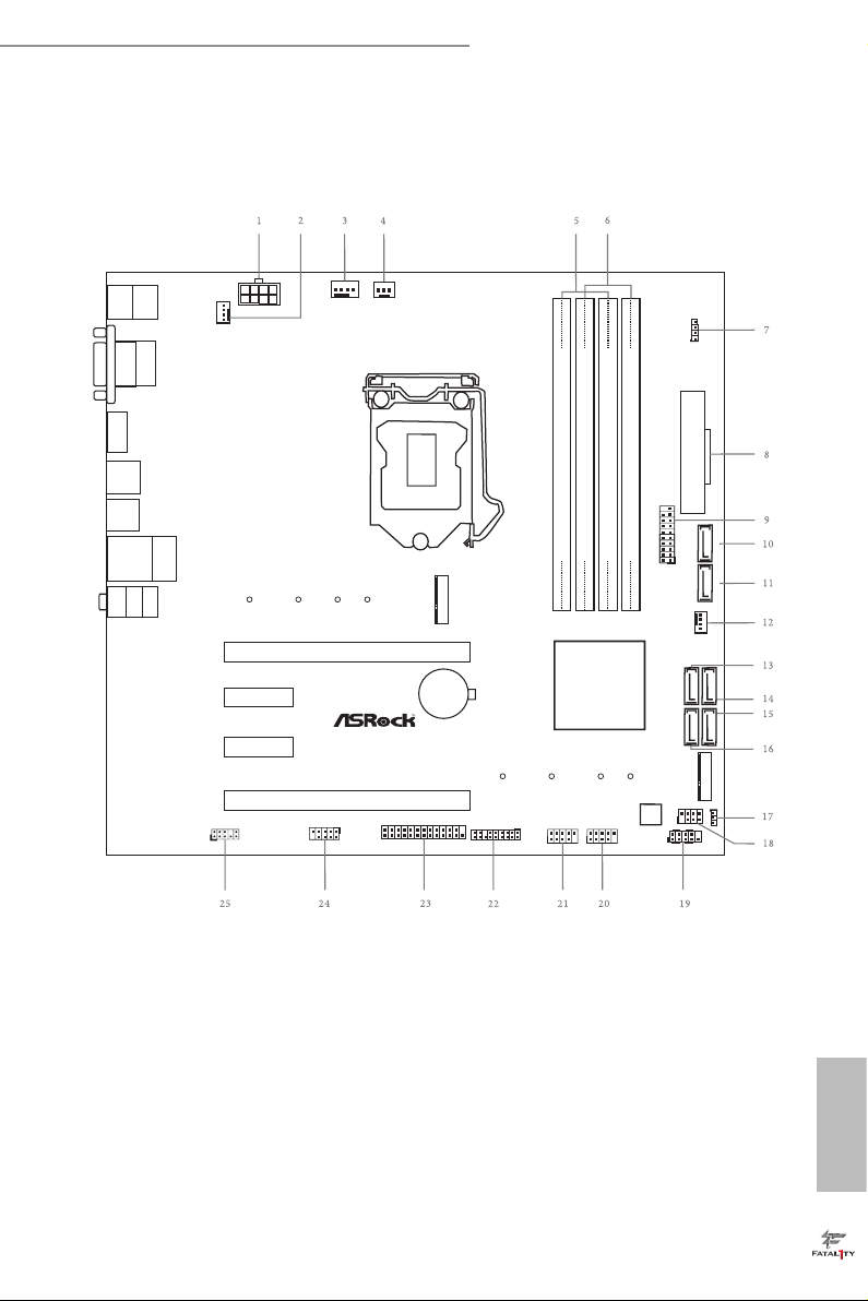
1.3 Motherboard Layout
English
7
Page 15

No. Description
1 ATX 12V Power Connector (ATX12V1)
2 Chassis Fan Connector (CHA_FAN1)
3 CPU Fan Connector (CPU_FAN1)
4 CPU Fan Connector (CPU_FAN2)
5 2 x 288-pin DDR4 DIMM Slots (DDR4_A1, DDR4_B1)
6 2 x 288-pin DDR4 DIMM Slots (DDR4_A2, DDR4_B2)
7 AURA RGB LED Header (RGB_HEADER1)
8 ATX Power Connector (ATXPWR1)
9 USB 3.0 Header (USB3_5_6)
10 SATA3 Connector (SATA3_0)
11 SATA3 Connector (SATA3_1)
12 Chassis Fan Connector (CHA_FAN2)
13 SATA3 Connector (SATA3_2)
14 SATA3 Connector (SATA3_3)
15 SATA3 Connector (SATA3_5)
16 SATA3 Connector (SATA3_4)
17 Clear CMOS Jumper (CLRMOS1)
18 Chassis Intrusion and Speaker Header (SPK_CI1)
19 System Panel Header (PANEL1)
20 USB 2.0 Header (USB5_6)
21 USB 2.0 Header (USB3_4)
22 TPM Header (TPMS1)
23 Print Port Header (LPT1)
24 COM Port Header (COM1)
25 Front Panel Audio Header (HD_AUDIO1)
English
8
Page 16
Fatal1ty B250M Performance Series
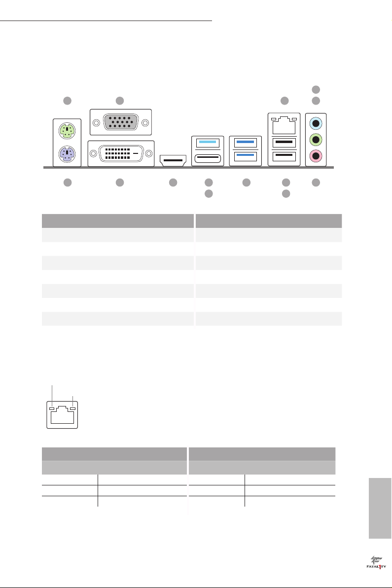
1.4 I/O Panel
1 3
2
4
5
14 6712
13
10
11
9
8
No. Description No. Description
1 PS/2 Mouse Port 8 USB 2.0 Port (USB2)
2 D-Sub Port 9 USB 3.0 Ports (USB3_3_4)
3 LAN RJ-45 Port* 10 USB 3.0 Type-A Port (USB3_TA_1)
4 Line In (Light Blue)** 11 USB 3.0 Type-C Port (USB3_TC_1)
5 Front Speaker (Lime)** 12 HDMI Port
6 Microphone (Pink)** 13 DVI-D Port
7 Fatal1ty Mouse Port (USB1) 14 PS/2 Keyboard Port
* ere are two LEDs on the LAN port. Please refer to the table below for the LAN port LED indications.
ACT/LINK L ED
SPEED LE D
LAN Por t
Activity / Link LED Speed LED
Status Description Status Description
O No Link O 10Mbps connection
Blinking Data Activity Orange 100Mbps connection
On Link Green 1Gbps connection
English
9
Page 17
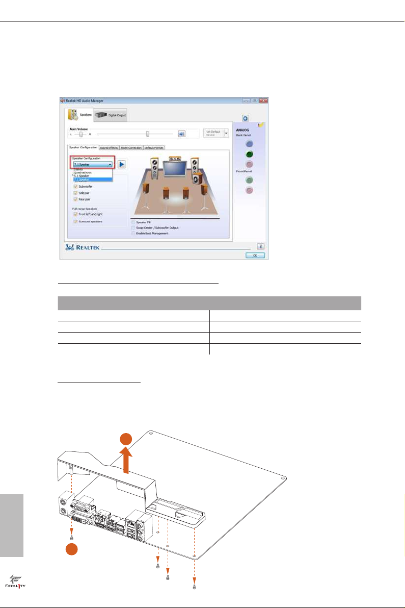
** To congure 7.1 CH HD Audio, it i s required to use an HD front panel audio module and enable the multichannel audio feature through the audio driver.
Please set Speaker Conguration to “7.1 Speaker”in the Realtek HD Audio Manager.
Function of the Audio Por ts in 7.1-channel Con guration:
Port Function
Light Blue (Rear panel) Rear Speaker Out
Lime (Rear panel) Front Speaker Out
Pink (Rear panel) Central /Subwoofer Speaker Out
Lime (Front panel) Side Speaker Out
English
10
How to Remove the I/O C over?
Certain graphics cards with e xtra thickness of the back plate may collid e with the pre-installed I/O cove r.
Before installing such a wider graphics card, please loosen the screws to remove the I/O cover, as the picture
shown below.
2
1
Page 18

Fatal1ty B250M Performance Series
Chapter 2 Installation
is is a Micro ATX form factor motherboard. Before you install the motherboard,
study the conguration of your chassis to ensure that the motherboard ts into it.
Pre-installation Precautions
Take note of the following precautions before you install motherboard components
or change any motherboard settings.
Make sure to unplug the power cord before installing or removing the motherboard
•
components. Failure to do so may cause physical injuries and damages to motherboard
components.
In order to avoid damage from static electricity to the motherboard’s components,
•
NEVER place your motherboard directly on a carpet. Also remember to use a grounded
wrist strap or touch a safety grounded object before you handle the components.
Hold components by the edges and do not touch the ICs.
•
Whenever you uninstall any components, place them on a grounded anti-static pad or
•
in the bag that comes with the components.
When placing screws to secure the motherboard to the chassis, please do not over-
•
tighten the screws! Doing so may damage the motherboard.
11
English
Page 19
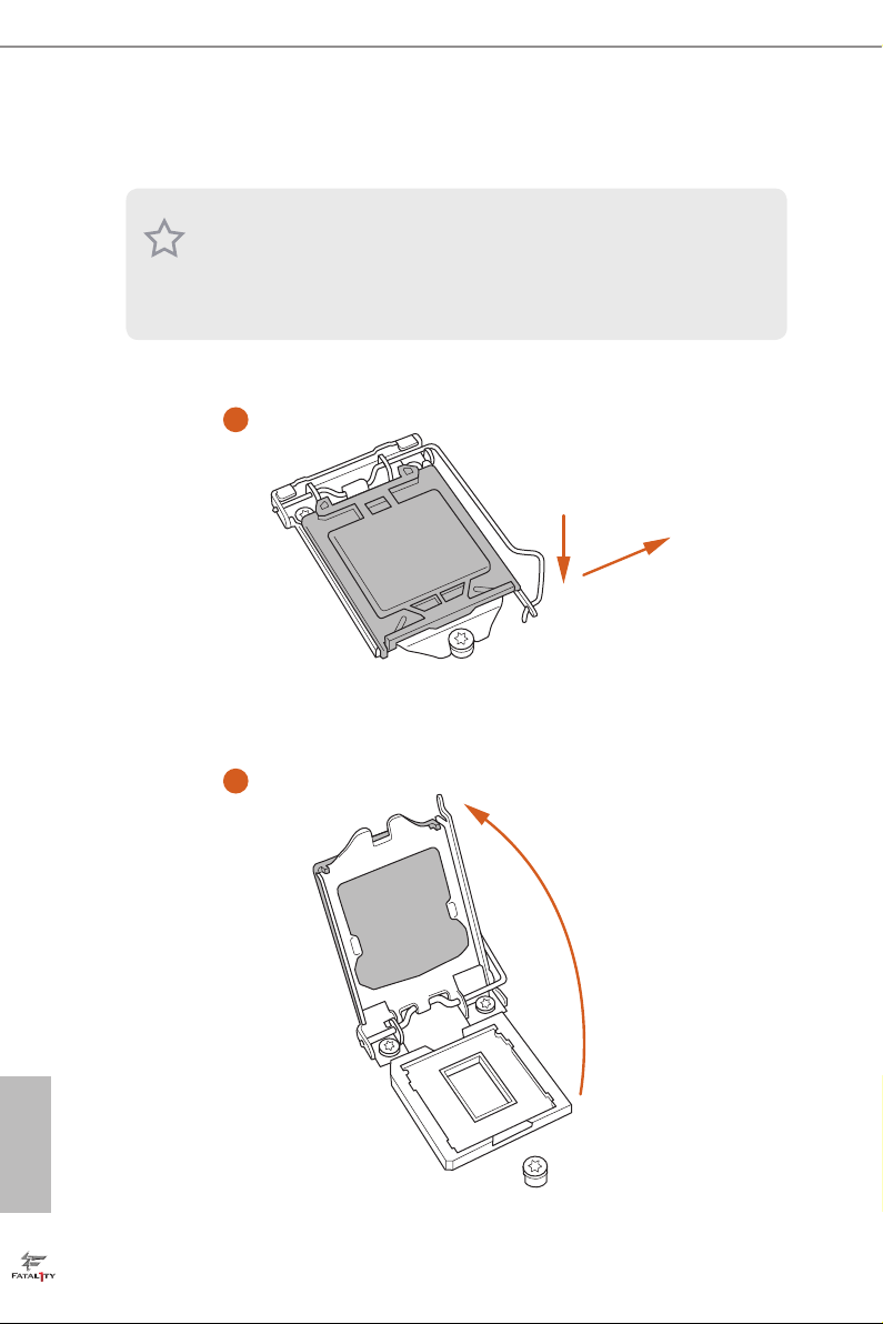
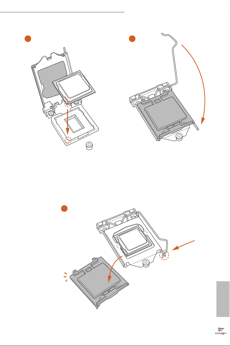
2.1 Installing the CPU
1. Before you insert the 1151-Pin CPU into the socket , please check if the PnP c ap
is on the socket, if the CPU sur face is unclean, or if th ere are any b ent pins in the
socket. Do not force to insert the CPU into the socket if above situ ation is found.
Other wise, the CPU wil l be seriously d amaged.
2. Unplug all power cables be fore installing the CPU.
1
2
A
B
English
12
Page 20
Fatal1ty B250M Performance Series
3
4
5
English
13
Page 21

Please save and replace the cover if the processor i s removed. e cover must be
placed if you wish to return the motherboard for aer service.
English
14
Page 22
Fatal1ty B250M Performance Series
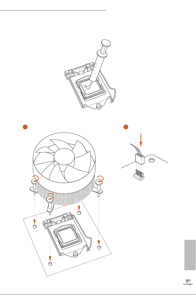
2.2 Installing the CPU Fan and Heatsink
1 2
FAN
CPU_
English
15
Page 23
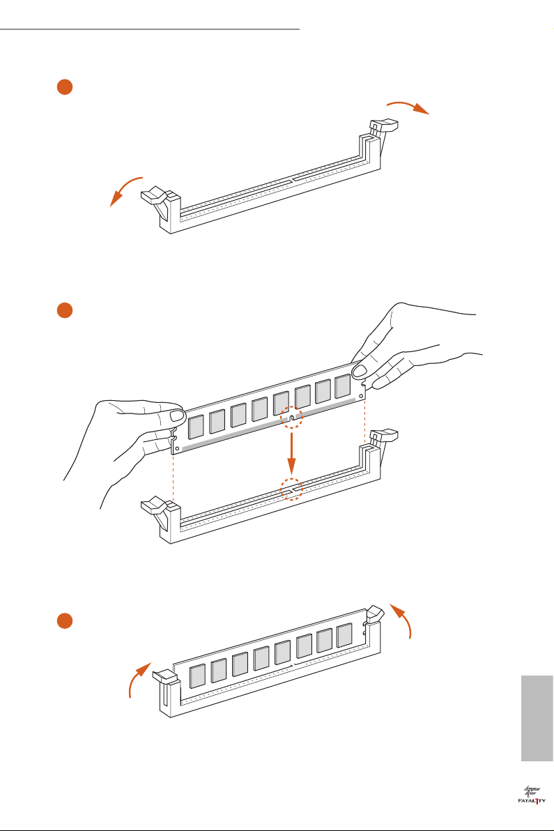
2.3 Installing Memory Modules (DIMM)
is motherboard provides four 288-pin DDR4 (Double Data Rate 4) DIMM slots,
and supports Dual Channel Memory Technology.
1. For dual channel conguration, you always need to install identical (the same
brand, speed , size and chip-type) DDR4 DIMM pairs.
2. It is unable to activate Dual Channel Memor y Technology with only one or three
memor y module installed.
3. It is not allowed to install a DDR, DDR2 or DDR3 memory module into a DDR4
slot; otherwise, this motherboard and DIMM may be damaged.
Dual Channel Memory Conguration
Priority DDR4_ A1 DDR4_ A2 DDR4_B1 DDR4_B2
1 Populated Populated
2 Populated Populated
3 Populated Populated Populated Populated
e DIMM only ts in one correct orientation. It will cause permanent dam age to
the mothe rboard and the DIMM if you force the DIMM into the slot at incor rect
orientation .
English
16
Page 24
Fatal1ty B250M Performance Series
1
2
3
English
17
Page 25

2.4 Expansion Slots (PCI Express Slots)
ere are 4 PCI Express slots on the motherboard.
Before installing an ex pansion card, please make sure that the power supply is
switched o or the power cord is unplugged. Plea se read the documentation of the
expan sion card and mak e necessary hardware settings for the card before you start
the installation.
PCIe slots:
PCIE1 (PCIe 3.0 x16 slot) is used for PCI Express x16 lane width graphics cards.
PCIE2 (PCIe 3.0 x1 slot) is used for PCI Express x1 lane width cards.
PCIE3 (PCIe 3.0 x1 slot) is used for PCI Express x1 lane width cards.
PCIE4 (PCIe 3.0 x16 slot) is used for PCI Express x4 lane width graphics cards.
PCIe Slot Congurations
PCIE1 PCIE4
Single Graphics Card x16 N/A
English
18
Two Graphics Cards in
CrossFireXTM Mode
1. For a better ther mal environment, ple ase connect a ch assi s fan to the motherboard’s chassis fan connector (CHA_FAN1 or CHA_ FAN2) when using multiple
graphics cards.
2. If PCIE2 sl ot or PCIE3 slot is occupied, the PCIe-ty pe M.2 device on M2_1 socket
will run at Gen3 x2 (16 Gb/s).
x16 x4
Page 26

2.5 Onboard Headers and Connectors
Onboard headers and connectors are NOT jumpers. Do NOT place jumper caps over
these header s and connectors. Placing jumper caps over the headers and connectors
will cause permanent damage to the motherboard.
Fatal1ty B250M Performance Series
System Panel Header
(9-pin PANEL1)
(see p.7, No. 19)
PWRBTN (Power Switch):
Connec t to the power switch on the chassi s front panel. You may congure the way to
turn o your system using the power switch.
RESET (Reset Switch):
Connec t to the reset switch on the chassi s front panel. P ress the reset sw itch to restart
the computer if the compute r freezes and fails to perform a normal restart.
PLED (Syste m Power LED):
Connec t to the power status indicator on the chassis front panel. e LED i s on when
the system is ope rating. e LED keeps blinking when the system i s in S1/S3 sleep
state. e LED is o when the system is in S4 sleep state or powered o (S5).
HDLED (Ha rd Drive Activity LED):
Connec t to the hard drive ac tivity LED on the chassis front panel. e LED is on
when the hard drive i s reading or writing data.
e front panel de sign may dier by chassis. A front pane l module mainly consists
of power switch , reset switch, power LED, hard dr ive activity LED, speak er and etc.
When connecting your chassis front panel module to this head er, make sure the wire
assig nments and the pin assig nments are matched correctly.
1
PLE D+
PLE D-
HDL ED-
HDL ED+
PWR BTN #
GND
RES ET#
GND
GND
Connect the power
switch, reset switch and
system status indicator on
the chassis to this header
according to the pin
assignments below. Note
the positive and negative
pins before connecting
the cables.
19
English
Page 27

Chassis Intrusion and
Speaker Header
(7-pin SPK_CI1)
(see p.7, No. 18)
DUM MY
+5V
1
SIG NAL
SPE AKE R
DUM MY
GND
DUM MY
Please connect the
chassis intrusion and the
chassis speaker to this
header.
English
Serial ATA3 Connectors
(SATA3_0:
see p.7, No. 10)
(SATA3_1:
see p.7, No. 11)
(SATA3_2:
see p.7, No. 13)
(SATA3_3:
see p.7, No. 14)
(SATA3_4:
see p.7, No. 16)
(SATA3_5:
see p.7, No. 15)
USB 2.0 Headers
(9-pin USB3_4)
(see p.7, No. 21)
(9-pin USB5_6)
(see p.7, No. 20)
USB 3.0 Header
(19-pin USB3_5_6)
(see p.7, No. 9)
SATA3_2
SATA3_4
USB _PW R
1
USB _PW R
IntA _PA_S SRX-
IntA _PA_S SRX+
IntA _PA_S STX-
IntA _PA_S STX+
IntA _PA_D -
IntA _PA_D +
Vbus
GND
GND
ese six SATA3
connectors support SATA
data cables for internal
SATA3_0
storage devices with up to
6.0 Gb/s data transfer rate.
SATA3_1
If M2_1 is occupied by a
SATA-type M.2 device,
SATA3_0 will be disabled.
SATA3_3
SATA3_5
ere are two headers
P-
P+
GND
DUM MY
on this motherboard.
Each USB 2.0 header can
support two ports.
GND
P+
P-
VbusVbus
IntA _PB_ SSRX -
IntA _PB_ SSRX +
GND
IntA _PB_ SSTX -
IntA _PB_ SSTX +
GND
IntA _PB_ D-
IntA _PB_ D+
Dumm y
1
ere is one header on
this motherboard. is
USB 3.0 header can
support two ports.
20
Page 28
Fatal1ty B250M Performance Series
GND
FAN_V OLTAGE _CO NTRO L
FAN_S PEE D
FAN_S PEE D_CO NTR OL
GND
FAN_V OLTAGE _CO NTR OL
FAN_S PEE D
FAN_S PEE D_C ONTR OL
GND
FAN_ VOLTAG E
FAN_ SPE ED
Front Panel Audio Header
(9-pin HD_AUDIO1)
(see p.7, No. 25)
1. High Denition Audio supports Jack Sensing, but the panel wire on the chassis
must support HDA to function correctly. Please follow the instructions in our
manual and chassis manual to install your system.
2. If you use an AC’97 audio panel, please install it to the front panel audio heade r by
the steps below:
A. Connect Mic_IN (MIC) to MIC2_ L.
B. Conne ct Audio_R (RIN) to OUT2_R and Audio_ L (LIN) to OUT2_ L.
C. Connect Ground (GND) to Ground (GND).
D. MIC_ RET and OUT_RET are for the HD audio panel only. You don’t need to
connec t them for the AC’97 audio panel.
E. To activate the front mic, go to the “FrontMic” Tab in the Realtek Control panel
and adju st “Recording Volume”.
Chassis Fan Connectors
(4-pin CHA_FAN1)
(see p.7, No. 2)
(4-pin CHA_FAN2)
(see p.7, No. 12)
GND
PRE SEN CE#
MIC _RE T
1
J_S ENS E
OUT 2_R
MIC 2_R
MIC 2_L
FAN _SP EE D_ CON TR OL
FAN _SP EE D
FAN _V OL TA GE
GND
OUT _RE T
OUT 2_L
is header is for
connecting audio devices
to the front audio panel.
Please connect fan cables
4
3
to the fan connector and
2
match the black wire to
1
the ground pin.
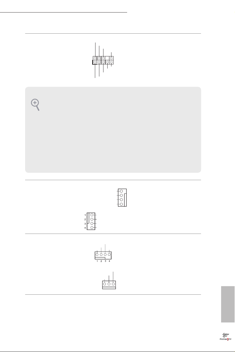
CPU Fan Connectors
(4-pin CPU_FAN1)
(see p.7, No. 3)
(3-pin CPU_FAN2)
(see p.7, No. 4)
is motherboard pro-
vides a 4-Pin CPU fan
(Quiet Fan) connector.
If you plan to connect a
3-Pin CPU fan, please
connect it to Pin 1-3.
English
21
Page 29

ATX Power Connector
5
1
8
(24-pin ATXPWR1)
(see p.7, No. 8)
12
24
is motherboard pro-
vides a 24-pin ATX power
connector. To use a 20-pin
ATX power supply, please
plug it along Pin 1 and Pin
1
13
13.
English
ATX 12V Power
Connector
(8-pin ATX12V1)
(see p.7, No. 1)
Serial Port Header
(9-pin COM1)
(see p.7, No. 24)
TPM Header
(17-pin TPMS1)
(see p.7, No. 22)
Print Port Header
(25-pin LPT1)
(see p.7, No. 23)
1
AFD #
STB #
ERR OR#
PIN I T#
SPD 1
SPD 0
GN D
D
GN
SLI N #
SPD 2
+3V S B
SER IRQ #
SPD 3
S_P WRD WN #
SPD 4
LAD 0
GN D
SPD 5
+3 V
LAD 1
SPD 6
GND
LAD 3
LAD 2
SPD 7
PC IRS T #
SMB _DA TA_ MAI N
ACK #
BUS Y
is motherboard pro-
vides an 8-pin ATX 12V
power connector. To use a
4-pin ATX power supply,
please plug it along Pin 1
and Pin 5.
is COM1 header
supports a serial port
module.
is connector supports Trusted
PC ICL K
FRA M E
Platform Module (TPM) system,
1
which can securely store keys,
digital certicates, passwords,
GN D
and data. A TPM system also
helps enhance network security,
SMB _CL K_M AIN
protects digital identities, and
ensures platform integrity.
is is an interface
for print port cable
that allows convenient
connection of printer
PE
SLC T
devices.
22
Page 30

Fatal1ty B250M Performance Series
AURA RGB LED Header
(4-pin RGB_HEADER1)
(see p.7, No. 7)
AURA RGB LED header is used
to connect RGB LED exten-
sion cable which allows users to
choose from various LED light-
ing eects.
23
English
Page 31

2.6 CrossFireXTM and Quad CrossFireXTM Operation Guide
is motherboard supports CrossFireXTM and Quad CrossFireXTM that allows you
to install up to three identical PCI Express x16 graphics cards.
1. You should only use ide ntical CrossFireXTM-ready g raphics cards that are AM D
certied.
2. Make sure that your g raphics card driver supports AMD CrossFireXTM technology.
Download the drivers from the A MD’s website: www.amd.com
3. Make sure that your power supply unit (PSU) can provide at least th e minimum
power your syste m require s. It is recommended to use a AMD certied PSU. Plea se
refer to the AMD’s website for d etail s.
4. If you pair a 12-pipe CrossFireXTM Edition card with a 16-pipe card, both cards will
operate a s 12-pipe cards while in CrossFireXTM mode.
5. Dierent CrossFireXTM cards may require dierent method s to enable CrossFireXTM. Please refer to A MD graphics card manuals for de tailed installation guide.
2.6.1 Installing Two CrossFireXTM-Ready Graphics Cards
Step 1
Insert one graphics card into PCIE1 slot
and the other graphics card to PCIE4 slot.
Make sure that the cards are properly
seated on the slots.
English
24
CrossFire Bridge
Step 2
Connect two graphics cards by installing
a CrossFire Bridge on the CrossFire Bridge
Interconnects on the top of the graphics
cards. (e CrossFire Bridge is provided
with the graphics card you purchase, not
bundled with this motherboard. Please
refer to your graphics card vendor for
details.)
Page 32

Fatal1ty B250M Performance Series
Step 3
Connect a VGA cable or a DVI cable to the
monitor connector or the DVI connec-
tor of the graphics card that is inserted to
PCIE1 slot.
25
English
Page 33

2.6.2 Driver Installation and Setup
Step 1
Power on your computer and boot into OS.
Step 2
Remove the AMD drivers if you have any VGA drivers installed in your system.
e Catalyst Uninstalle r is an optional downloa d. We recommend using this utility
to uninstall any previously installed Catalyst drivers prior to installation. Pl ease
check A MD’s website for AMD driver update s.
Step 3
Install the required drivers and CATALYST Control Center then restart your
computer. Please check AMD’s website for details.
Step 4
Double-click the AMD Catalyst Control
AMD Catalyst Control Center
Center icon in the Windows® system tray.
Step 5
In the le pane, click Performance and
then AMD CrossFireXTM. en select
Enable AMD CrossFireX and click Apply.
Select the GPU number according to your
graphics card and click Apply.
English
26
Page 34
Fatal1ty B250M Performance Series
2.7 M.2_SSD (NGFF) Module Installation Guide
The M.2, also known as the Next Generat ion Form Factor (NGFF), is a small size and
versatile card edge connector that aims to replace mPCIe and mSATA. The Ultra M.2
Socket (M2_1) supports type 2230/2242/2260/2280 M.2 SATA3 6.0 Gb/s module and M.2
PCI Express module up to Gen3 x4 (32 Gb/s). e Ultra M.2 Socket (M2_2) supports type
2230/2242/2260/2280 M.2 PCI Express module up to Gen3 x4 (32 Gb/s).
* Please be noted that if M2_1 is occupied by a SATA-type M.2 device, SATA3_0 will be
disabled.
* If PCIE2 slot or PCIE3 slot is occupied, the PCIe-type M.2 device on M2_1 socket will
run at Gen3 x2 (16 Gb/s).
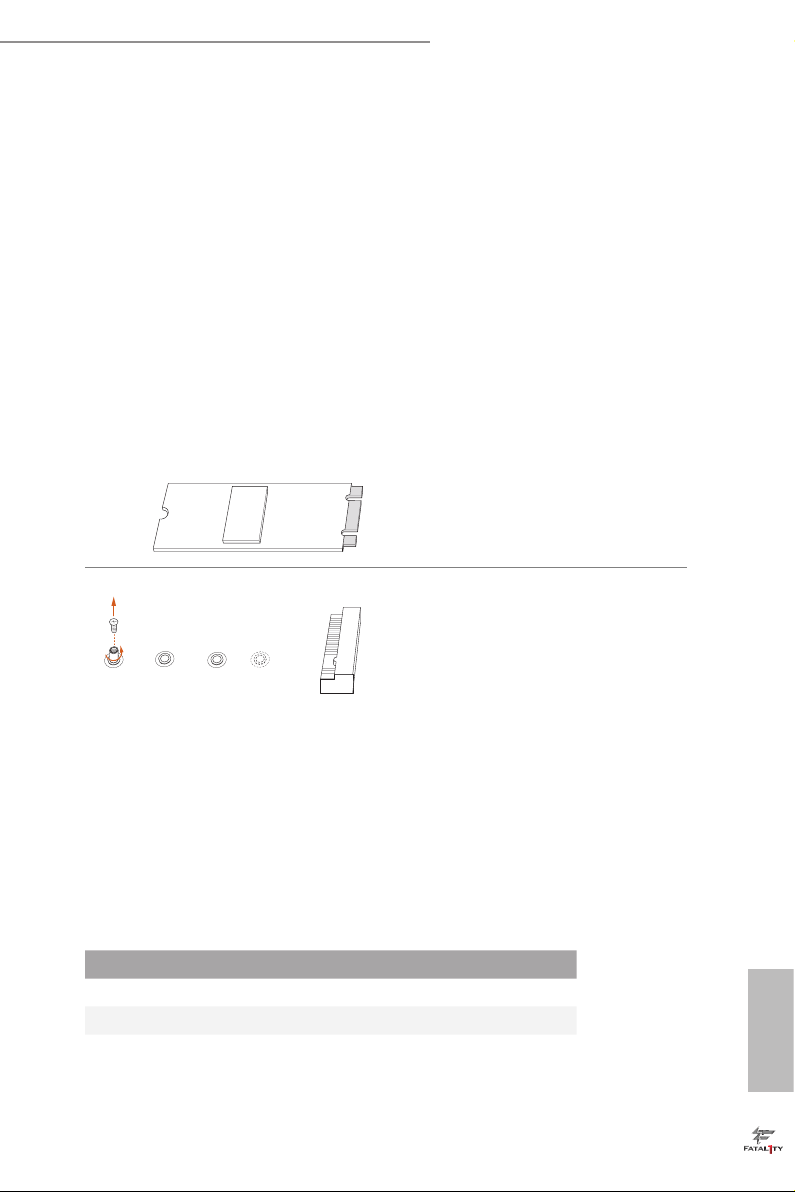
Installing the M.2_SSD (NGFF) Module
Step 1
Prepare a M.2_SSD (NGFF) module
and the screw.
Step 2
Depending on the PCB type and
A
BCD
No. 1 2 3 4
Nut Location A B C D
PCB Length 3cm 4.2cm 6cm 8cm
Module Type Type2230 Type 2242 Type2260 Type 2280
length of your M.2_SSD (NGFF)
module, nd the corresponding nut
location to be used.
English
27
Page 35

4
5
3
Step 3
Move the stando based on the
module type and length.
e stando is placed at the nut
2
1
location D by default. Skip Step 3 and
4 and go straight to Step 5 if you are
going to use the default nut.
Otherwise, release the stando by
hand.
Step 4
Peel o the yellow protective lm on
A
BCD
the nut to be used. Hand tighten the
stando into the desired nut location
on the motherboard.
English
28
ABCDE
Align and gently insert the M.2
(NGFF) SSD module into the M.2
slot. Please be aware that the M.2
(NGFF) SSD module only ts in one
orientation.
Step 5
BC
A
Step 6
Tighten the screw with a screwdriver
to secure the module into place.
NUT1NUT2D
Please do not overtighten the screw as
this might damage the module.
Page 36

Fatal1ty B250M Performance Series
M.2_SSD (NGFF) Module Support List
Vendor Size Interface Length P/N
ADATA 128GB SATA3 2280 AXNS381E-128GM-B
ADATA 256GB SATA3 2280 AXNS381E-256GM-B
ADATA 32GB SATA3 2230 AXNS330E-32GM-B
Crucial 120GB SATA3 2280 CT120M500SSD4
Crucial 240GB SATA3 2280 CT240M500SSD4
Intel 80GB SATA3 2280 Intel SSDSCKGW080A401/80G
Intel 256GB PCIe3 x4 2280 SSDPEKKF256G7
Intel 512GB PCIe3 x4 2280 SSDPEKKF512G7
Kingston 120GB SATA3 2280 SM2280S3
Kingston 480GB PCIe2 x4 2280 SH2280S3/480G
OCZ 512GB PCIe3 x4 2280 RVD400 -M2280-512G (NVME)
Plextor 128GB PCIe3 x4 2280 PX-128M8PeG
Plextor 1TB PCIe3 x4 2280 PX-1TM8PeG
Plextor 256GB PCIe3 x4 2280 PX-256M8PeG
Plextor 256GB PCIe 2280 PX-G256M6e
Plextor 512GB PCIe3 x4 2280 PX-512M8PeG
Plextor 512GB PCIe 2280 PX-G512M6e
Samsung 256GB PCIe3 x4 2280 SM951 (MZHPV256HDGL)
Samsung 256GB PCIe3 x4 2280 SM951 (NVME)
Samsung 512GB PCIe3 x4 2280 SM951 (MZHPV512HDGL)
Samsung 512GB PCIe3 x4 2280 SM951 (NVME)
Samsung 512GB PCIe x4 2280 XP941-512G (MZHPU512HCGL)
SanDisk 128GB PCIe 2260 SD6PP4M-128G
SanDisk 256GB PCIe 2260 SD6PP4M-256G
Team 128GB SATA3 2242 TM4PS4128GMC105
Team 128GB SATA3 2280 TM8PS4128GMC105
Team 256GB SATA3 2280 TM8PS4256GMC105
Team 256GB SATA3 2242 TM4PS4256GMC105
Transcend 256GB SATA3 2242 TS256GMTS400
Transcend 512GB SATA3 2260 TS512GMTS600
Transcend 512GB SATA3 2280 TS512GMTS800
V-Color 120GB SATA3 2280 VLM100-120G-2280B-RD
V-Color 240GB SATA3 2280 VLM100-240G-2280B-RD
V-Color 240GB SATA3 2280 VSM100-240G-2280
For the latest updates of M.2 _SSD (NFGG) module support list, please visit our website
for details: http://www.asrock.com
English
29
Page 37

Chapter 3 Software and Utilities Operation
3.1 Installing Drivers
e Support CD that comes with the motherboard contains necessary drivers and
useful utilities that enhance the motherboard’s features.
Running The Support CD
To begin using the support CD, insert the CD into your CD-ROM drive. e CD
automatically displays the Main Menu if “AUTORUN” is enabled in your computer.
If the Main Menu does not appear automatically, locate and double click on the le
“ASRSETUP.EXE” in the Support CD to display the menu.
Drivers Menu
e drivers compatible to your system will be auto-detected and listed on the
support CD driver page. Please click Install All or follow the order from top to
bottom to install those required drivers. erefore, the drivers you install can work
properly.
Utilities Menu
e Utilities Menu shows the application soware that the motherboard supports.
Click on a specic item then follow the installation wizard to insta ll it.
To improve Windows 7 compatibility, please download and install the following hot
x provided by Microso.
“KB2720599”: http://support.microso.com/ kb/2720599/en-us
English
30
Page 38

Fatal1ty B250M Performance Series
3.2 ASRock Live Update & APP Shop
e ASRock Live Update & APP Shop is an online store for purchasing and
downloading soware applications for your ASRock computer. You can quick ly and
easily insta ll various apps and support utilities. With ASRock Live Update & APP
Shop, you can optimize your system and keep your motherboard up to date simply
with a few clicks.
Double-click on your desktop to access ASRock Live Update & APP Shop
utility.
*You need to be connected to the Internet to download apps f rom the ASRock Live Update & APP Shop.
3.2.1 UI Overview
Category Panel
Hot News
Information Panel
Category Panel: e category panel contains several category tabs or buttons that
when selected the information panel below displays the relative information.
Information Panel: e information panel in the center displays data about the
currently selected category and allows users to perform job-related tasks.
Hot News: e hot news section displays the various latest news. Click on the image
to visit the website of the selected news and know more.
English
31
Page 39
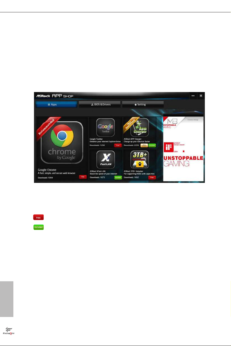
3.2.2 Apps
When the "Apps" tab is selected, you will see all the available apps on screen for you
to download.
Installing an App
Step 1
Find the app you want to install.
e most recommended app appears on the le side of the screen. e other various
apps are shown on the right. Please scroll up and down to see more apps listed.
English
32
You can check the price of the app and whether you have already intalled it or not.
- e red icon displays the price or "Free" if the app is free of charge.
- e green "Installed" icon means the app is installed on your computer.
Step 2
Click on the app icon to see more details about the selected app.
Page 40

Fatal1ty B250M Performance Series
Step 3
If you want to install the app, click on the red icon to start downloading.
Step 4
When installation completes, you can nd the green "Installed " icon appears on the
upper right corner.
To uninstall it, simply click on the trash can icon .
*e trash icon may not appear for certain apps.
English
33
Page 41
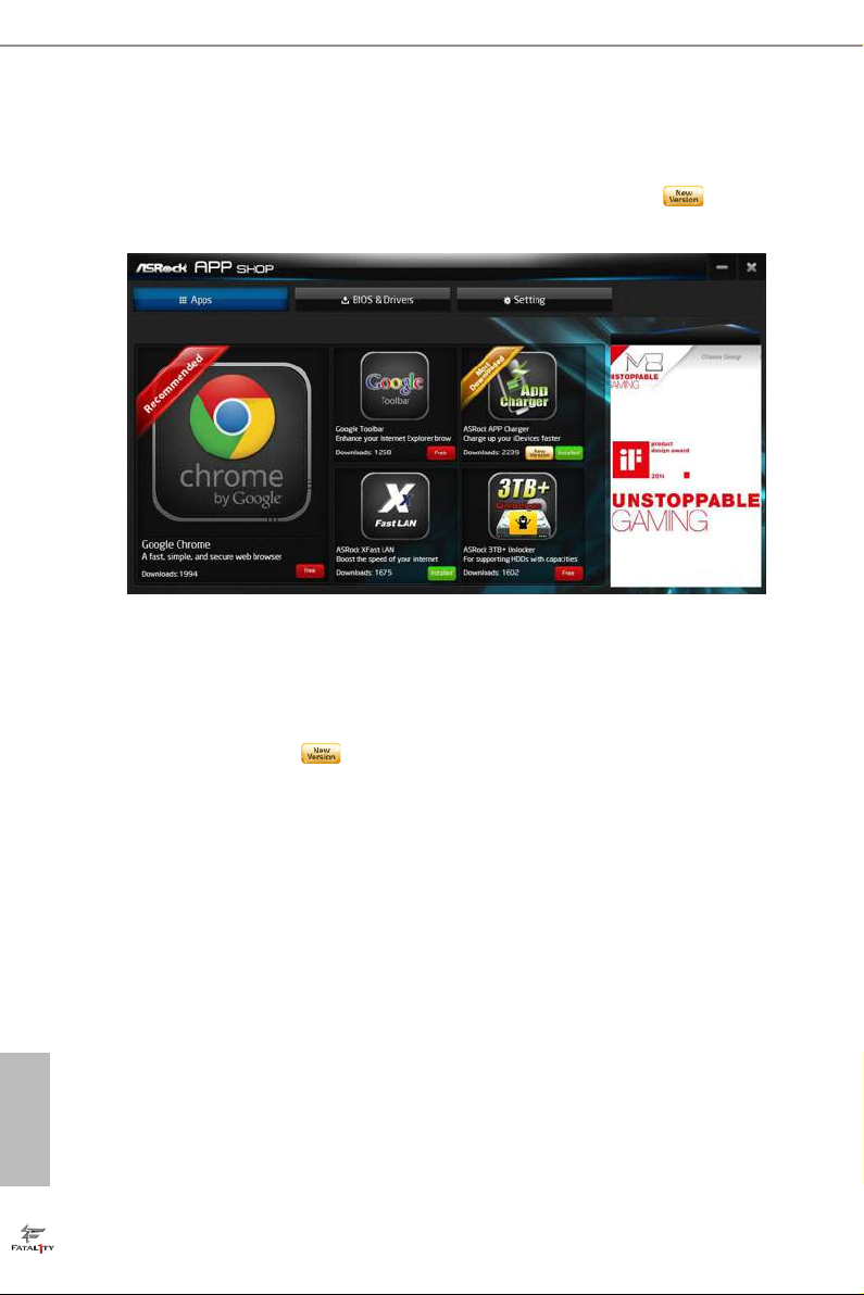
Upgrading an App
You can only upgrade the apps you have already installed. When there is an
available new version for your app, you will nd the mark of "New Version"
appears below the installed app icon.
Step 1
Click on the app icon to see more details.
Step 2
Click on the yellow icon to start upgrading.
English
34
Page 42

Fatal1ty B250M Performance Series
3.2.3 BIOS & Drivers
Installing BIOS or Drivers
When the "BIOS & Drivers" tab is selected, you will see a list of recommended or
critical updates for the BIOS or drivers. Please update them all soon.
Step 1
Please check the item information before update. Click on to see more details.
Step 2
Click to select one or more items you want to update.
Step 3
Click Update to start the update process.
English
35
Page 43

3.2.4 Setting
In the "Setting" page, you can change the language, select the server location, and
determine if you want to automatically run the ASRock Live Update & APP Shop
on Windows startup.
English
36
Page 44
Fatal1ty B250M Performance Series
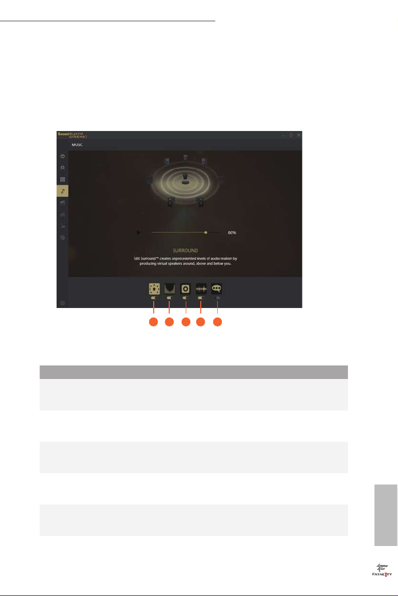
3.3 Creative SoundBlaster Cinema3
e SoundBlasterTM Cinema3, powered by the SBX Pro Studio technologies, is designed to
bring the same great audio experience found in live performances, lms, and recording
studios to the PC. With this utility, you can easily enhance your audio environment in
ve modes, including Headphones, Speakers, Music, Movie, Game, Voice and Custom.
1 2 3 4 5
ere are ve functions in SoundBlasterTM Cinema3:
No. Function Description
Surround
1
Crystalizer
2
Bass
3
Smart Volume
4
Dialog Plus
5
Creating unprecedented levels of audio realism by producing
virtual speakers around, above and below you.
Making music sound as good as the artist originally
intended by ensuring that every audio detail is heard.
Enhancing bass sound experience by expanding the low
frequency tones.
Minimizing abrupt volume changes by automatically
adjusting the loudness of your audio playback.
Enhancing voices in music and movies for drastically clearer
vocal range.
English
37
Page 45

3.4 Enabling USB Ports for Windows® 7 Installation
Intel® new processors have removed their support for the Enhanced Host Controller
Interface (EHCI – USB2.0) and only kept the eXtensible Host Controller Interface
(XHCI – USB3.0). Due to that fact that XHCI is not included in the Windows 7
inbox drivers, users may nd it dicult to install Windows 7 operating system
because the USB ports on their motherboard won’t work. In order for the USB ports
to function properly, please create a Windows® 7 installation disk with the Intel®
USB 3.0 eXtensible Host Controller (xHCI) drivers packed into the ISO le.
Requirements
A Windows® 7 installation disk or USB drive
•
A Windows® PC
•
Win7 USB Patcher (included in the ASRock Support CD or downloaded from
•
website)
Scenarios
You have an ODD and PS/2 ports:
If there is an optical disc drive, PS/2 ports and PS/2 Keyboard or mouse on your computer,
you can skip the instructions below and go ahead to install Windows® 7 OS.
You’ve got nothing:
If you do not have an optical disc drive, please nd another computer and follow the
instructions below to create a new ISO le with the “Win7 USB Patcher”. en use the new
patched Windows® 7 installation USB drive to install Windows® 7 OS.
English
38
Page 46
Fatal1ty B250M Performance Series
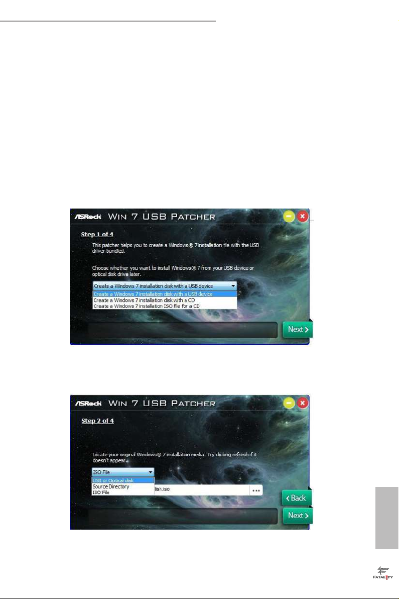
Instructions
Step 1
Insert the Windows® 7 installation disk or USB drive to your system.
Step 2
Extract the tool (Win7 USB Patcher) and launch it.
Step 3
Select how you want to install Windows 7 later.
Step 4
Locate your Win7 source folder or your ISO le.
English
39
Page 47

Step 5
Select the USB storage, compact disk or destination folder for the new Windows 7
installation le.
Step 6
Click “Start” to begin.
English
40
Step 7
Now you are able to install Windows® 7 on Intel® new processors with the new burned CD.
Or please use the patched ISO image to make an OS USB drive to install the OS.
Page 48

Fatal1ty B250M Performance Series
Chapter 4 UEFI SETUP UTILITY
4.1 Introduction
is section explains how to use the UEFI SETUP UTILITY to congure your
system. You may run the UEFI SETUP UTILITY by pressing <F2> or <Del> right
aer you power on the computer, other wise, the Power-On-Self-Test (POST) will
continue with its test routines. If you wish to enter the UEFI SETUP UTILITY aer
POST, restart the system by pressing <Ctl> + <Alt> + <Delete>, or by pressing the
reset button on the system chassis. You may also restart by turning the system o
and then back on.
Becau se the UEFI soware is constantly being upd ated, the following UEFI setup
screens and de scriptions are for reference purpose only, and they may not exactly
match what you see on your scre en.
41
English
Page 49

4.2 EZ Mode
e EZ Mode screen appears when you enter the BIOS setup program by default. EZ
mode is a dashboard which contains multiple readings of the system’s current status.
You can check the most crucial information of your system, such as CPU speed,
DRAM frequency, SATA information, fan speed, etc.
Press <F6> or click the "Advanced Mode" button at the upper right corner of the
screen to switch to "Advanced Mode" for more options.
1 2 3 4 5 6
English
42
No. Function
Help
1
Load UEFI Defaults
2
Save Changes and Exit
3
Discard Changes
4
Change Language
5
Switch to Advanced Mode
6
Page 50

Fatal1ty B250M Performance Series
4.3 Advanced Mode
e Advanced Mode provides more options to congure the BIOS settings. Refer to
the following sections for the detailed congurations.
To access the EZ Mode, press <F6> or click the "EZ Mode" button at the upper right
corner of the screen.
4.3.1 UEFI Menu Bar
e top of the screen has a menu bar with the following selections:
Main
OC Tweaker
Advanced
Tool
H/W Monitor
Boot
Security
Exit
For setting system time/date information
For overclocking congurations
For advanced system congurations
Useful tools
Displays current hardware status
For conguring boot settings and boot priority
For security settings
Exit the current screen or the UEFI Setup Utility
43
English
Page 51

4.3.2 Navigation Keys
Use < > key or < > key to choose among the selections on the menu bar, and
use < > key or < > key to move the cursor up or down to select items, then
press <Enter> to get into the sub screen. You can also use the mouse to click your
required item.
Please check the following table for the descriptions of each navigation key.
Navigation Key(s) Description
+ / -
<Tab>
<PGUP>
<PGDN>
<HOME>
<END>
<F1>
<F5>
<F7>
<F9>
<F10>
<F12>
<ESC>
To change option for the selected items
Switch to next function
Go to the previous page
Go to the next page
Go to the top of the screen
Go to the bottom of the screen
To display the General Help Screen
Add / Remove Favorite
Discard changes and exit the SETUP UTILITY
Load optimal default values for all the settings
Save changes and exit the SETUP UTILITY
Print screen
Jump to the Exit Screen or exit the current screen
English
44
Page 52
Fatal1ty B250M Performance Series
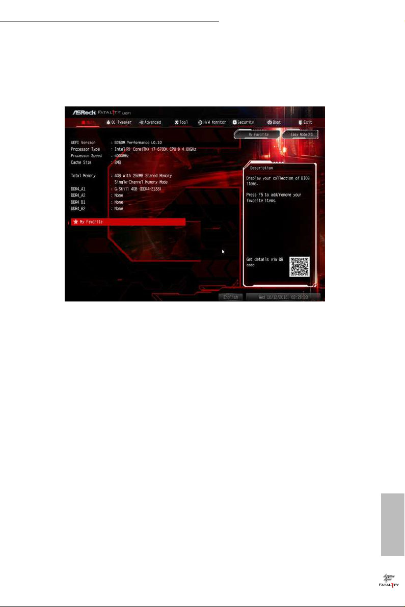
4.4 Main Screen
When you enter the UEFI SETUP UTILITY, the Main screen will appear and
display the system overview.
My Favorite
Display your collection of BIOS items. Press F5 to add/remove your favorite items.
45
English
Page 53

4.5 OC Tweaker Screen
In the OC Tweaker screen, you can set up overclocking features.
Becau se the UEFI soware is constantly being upd ated, the following UEFI setup
screens and de scriptions are for reference purpose only, and they may not exactly
match what you see on your scre en.
English
46
CPU Conguration
Boot Performance Mode
Select the performance state that the BIOS will set before OS hando.
FCLK Frequency
Congure the FCLK Frequency.
Intel SpeedStep Technology
Intel SpeedStep technology allows processors to switch between multiple frequen-
cies and voltage points for better power saving and heat dissipation.
Intel Turbo Boost Technology
Intel Turbo Boost Technology enables the processor to run above its base operating
frequency when the operating system requests the highest performance state.
Page 54

Fatal1ty B250M Performance Series
Intel Speed Shift Technology
Enable/Disable Intel Speed Shi Technology support. Enabling will expose the
CPPC v2 interface to allow for hardware controlled P-states.
Long Duration Power Limit
Congure Package Power Limit 1 in watts. When the limit is exceeded, the CPU
ratio will be lowered aer a period of time. A lower limit can protect the CPU and
save power, while a higher limit may improve performance.
Long Duration Maintained
Congure the period of time until the CPU ratio is lowered when the Long
Duration Power Limit is exceeded.
Short Duration Power Limit
Congure Package Power Limit 2 in watts. When the limit is exceeded, the CPU
ratio will be lowered immediately. A lower limit can protect the CPU and save
power, while a higher limit may improve performance.
System Agent Current Limit
Congure the current limit of the system agent. A lower limit can protect the CPU
and save power, while a higher limit may improve performance.
CPU Core Current Limit
Congure the current limit of the CPU core. A lower limit can protect the CPU and
save power, while a higher limit may improve performance.
GT Slice Current Limit
Congure the current limit of the GT slice. A lower limit can protect the CPU and
save power, while a higher limit may improve performance.
GT Frequency
Congure the frequency of the integrated GPU.
DRAM Conguration
DRAM Tweaker
Fine tune the DRAM settings by leaving marks in checkboxes. Click OK to conrm and
apply your new settings.
DRAM Timing Conguration
English
47
Page 55

Load XMP Setting
Load XMP settings to overclock the memory and perform beyond standard specications.
DRAM Reference Clock
Select Auto for optimized settings.
DRAM Frequency
If [Auto] is selected, the motherboard will detect the memory module(s) inserted
and assign the appropriate frequency automatically.
Primary Timing
CAS# Latency (tCL)
e time between sending a column address to the memory and the beginning of the data
in response.
RAS# to CAS# Delay and Row Precharge (tRCDtRP)
RAS# to CAS# Delay : e number of clock cycles required between the opening of a row
of memory and accessing columns within it.
Row Precharge: e number of clock cycles required between the issuing of the precharge
command and opening the next row.
RAS# Active Time (tRAS)
e number of clock cycles required between a bank active command and issuing the
precharge command.
English
48
Command Rate (CR)
e delay between when a memor y chip is selected and when the rst active command can
be issued.
Secondary Timing
Write Recovery Time (tWR)
e amount of delay that must elapse aer the completion of a valid write operation,
before an active bank can be precharged.
Refresh Cycle Time (tRFC)
e number of clocks from a Refresh command until the rst Activate command to
the same rank.
RAS to RAS Delay (tRRD_L)
Page 56

Fatal1ty B250M Performance Series
e number of clocks between two rows activated in dierent banks of the same
rank.
RAS to RAS Delay (tRRD_S)
e number of clocks between two rows activated in dierent banks of the same
rank.
Write to Read Delay (tWTR_L)
e number of clocks between the last valid write operation and the next read command to
the same interna l bank.
Write to Read Delay (tWTR_S)
e number of clocks between the last valid write operation and the next read command to
the same interna l bank.
Read to Precharge (tRTP)
e number of clocks that are inserted between a read command to a row pre-
charge command to the same rank.
Four Activate Window (tFAW)
e time window in which four activates are allowed the same rank.
CAS Write Latency (tCWL)
Congure CAS Write Latency.
Third Timing
tREFI
Congure refresh cycles at an average periodic interval.
tCKE
Congure the period of time the DDR4 initiates a minimum of one refresh
command internally once it enters Self-Refresh mode.
tRDRD_sg
Congure between module read to read delay.
tRDRD_dg
Congure between module read to read delay.
tRDRD_dr
English
49
Page 57

Congure between module read to read delay.
tRDRD_dd
Congure between module read to read delay.
tRDWR_sg
Congure between module read to write delay.
tRDWR_dg
Congure between module read to write delay.
tRDWR_dr
Congure between module read to write delay.
tRDWR_dd
Congure between module read to write delay.
tWRRD_sg
Congure between module write to read delay.
tWRRD_dg
Congure between module write to read delay.
tWRRD_dr
Congure between module write to read delay.
English
50
tWRRD_dd
Congure between module write to read delay.
tWRWR_sg
Congure between module write to write delay.
tWRWR_dg
Congure between module write to write delay.
tWRWR_dr
Congure between module write to write delay.
tWRWR_dd
Congure between module write to write delay.
Page 58

Fatal1ty B250M Performance Series
Advanced Setting
MRC Fast Boot
Enable Memory Fast Boot to skip DRAM memory training for booting faster.
Voltage Conguration
CPU Vcore Voltage
Congure the voltage for the CPU Vcore.
CPU Load-Line Calibration
CPU Load-Line Calibration helps prevent CPU voltage droop when the system is
under heav y loading.
GT Voltage
Congure the voltage for the integrated GPU.
GT Load-Line Calibration
GT Load-Line Calibration helps prevent integrated GPU voltage droop when the
system is under heav y load.
DRAM Voltage
Use this to congure DRAM Voltage. e default value is [Auto].
PCH +1.0 Voltage
Congure the chipset voltage (1.0V).
VCCIO Voltage
Congure the voltage for the VCCIO.
VCCST Voltage
Congure the voltage for the VCCST.
VCCSA Voltage
Congure the voltage for the VCCSA.
Save User Default
Type a prole name and press enter to save your settings as user default.
Load User Default
Load previously saved user defaults.
English
51
Page 59

4.6 Advanced Screen
In this section, you may set the congurations for the following items: CPU
Conguration, Chipset Conguration, Storage Conguration, Super IO Congura-
tion, ACPI Conguration, USB Conguration and Trusted Computing.
Setting wrong values in this sec tion may cause the system to malfunction.
English
52
UEFI Conguration
UEFI Setup Style
Select the default mode when entering the UEFI setup utility.
Active Page on Entry
Select the default page when entering the UEFI setup utility.
Full HD UEFI
When [Auto] is selected, the resolution will be set to 1920 x 1080 if the monitor
supports Full HD resolution. If the monitor does not support Full HD resolution,
then the resolution will be set to 1024 x 768. When [Disable] is selected, the
resolution will be set to 1024 x 768 directly.
Page 60
Fatal1ty B250M Performance Series
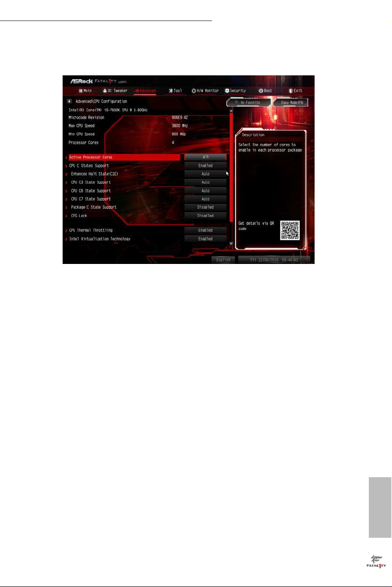
4.6.1 CPU Conguration
Intel Hyper Threading Technology
Intel Hyper reading Technology allows multiple threads to run on each core, so
that the overall performance on threaded soware is improved.
Active Processor Cores
Select the number of cores to enable in each processor package.
CPU C States Support
Enable CPU C States Support for power saving. It is recommended to keep C3, C6
and C7 all enabled for better power saving.
Enhanced Halt State (C1E)
Enable Enhanced Halt State (C1E) for lower power consumption.
CPU C3 State Support
Enable C3 sleep state for lower power consumption.
CPU C6 State Support
Enable C6 deep sleep state for lower power consumption.
CPU C7 State Support
Enable C7 deep sleep state for lower power consumption.
English
53
Page 61

Package C State Support
Enable CPU, PCIe, Memory, Graphics C State Support for power saving.
CFG Lock
is item allows you to disable or enable the CFG Lock.
CPU Thermal Throttling
Enable CPU internal thermal control mechanisms to keep the CPU from overheat-
ing.
Intel Virtualization Technology
Intel Virtualization Technology allows a platform to run multiple operating systems
and applications in independent partitions, so that one computer system can
function as multiple virtual systems.
Hardware Prefetcher
Automatically prefetch data and code for the processor. Enable for better
performance.
Adjacent Cache Line Prefetch
Automatically prefetch the subsequent cache line while retrieving the currently
requested cache line. Enable for better performance.
SW Guard Extensions (SGX)
Intel SGX is a set of new CPU instructions that can be used by applications to set
aside private regions of code and data.
English
54
Page 62

4.6.2 Chipset Conguration
Primary Graphics Adapter
Select a primary VGA.
Fatal1ty B250M Performance Series
Top Of Lower Usable Dram
Maximum Value of TOLUD. Dynamic assignment would adjust TOLUD
automatically based on largest MMIO length of installed graphic controller.
VT-d
Intel® Virtualization Technology for Directed I/O helps your virtual machine
monitor better utilize hardware by improving application compatibility and
reliability, and providing additional levels of manageability, security, isolation, and
I/O performance.
PCIE1 Link Speed
Select the link speed for PCIE1.
PCIE2 Link Speed
Select the link speed for PCIE2.
PCIE3 Link Speed
Select the link speed for PCIE3.
English
55
Page 63

PCIE4 Link Speed
Select the link speed for PCIE4.
PCI Express Native Control
Select Enable for enhanced PCI Express power saving in OS.
PCIE ASPM Support
is option enables/disables the ASPM support for all CPU downstream devices.
PCH PCIE ASPM Support
is option enables/disables the ASPM support for all PCH PCIE devices.
DMI ASPM Support
is option enables/disables the control of ASPM on CPU side of the DMI Link.
PCH DMI ASPM Support
is option enables/disables the ASPM support for all PCH DMI devices.
IOAPIC 24-119 Entries
I/O APICs contain a redirection table, which is used to route the interrupts it receives from
peripheral buses to one or more local APICs. Enable/disable IOAPIC 24-119 Entries to
expand to PIROI-PIROX.
Share Memory
English
56
Congure the size of memory that is allocated to the integrated graphics processor when
the system boots up.
IGPU Multi-Monitor
Select disable to disable the integrated graphics when an external graphics card is installed.
Select enable to keep the integrated graphics enabled at all times.
Onboard LAN
Enable or disable the onboard network interface controller.
Onboard HD Audio
Enable/disable onboard HD audio. Set to Auto to enable onboard HD audio and
automatically disable it when a sound card is installed.
Front Panel
Enable/disable front panel HD audio.
Page 64

Fatal1ty B250M Performance Series
Onboard HDMI HD Audio
Enable audio for the onboard digital outputs.
Deep Sleep
Congure deep sleep mode for power saving when the computer is shut down.
Restore on AC/Power Loss
Select the power state aer a power failure. If [Power O] is selected, the power will
remain o when the power recovers. If [Power On] is selected, the system will start
to boot up when the power recovers.
57
English
Page 65
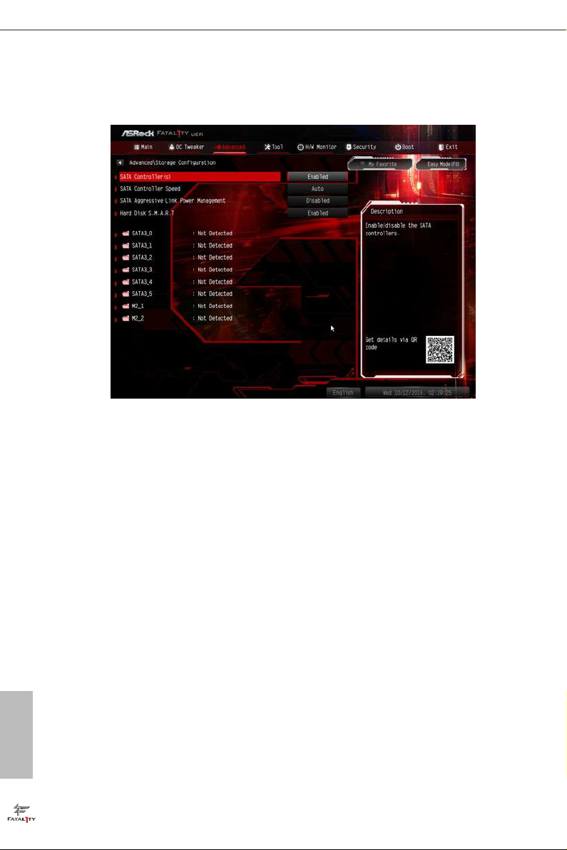
4.6.3 Storage Conguration
SATA Controller(s)
Enable/disable the SATA controllers.
SATA Controller Speed
Indicates the maximum speed the SATA controller can support.
English
58
SATA Aggressive Link Power Management
SATA Aggressive Link Power Management allows SATA devices to enter a low
power state during periods of inactivity to save power. It is only supported by AHCI
mode.
Hard Disk S.M.A.R.T.
S.M.A.R.T stands for Self-Monitoring, Analysis, and Reporting Technolog y. It is a
monitoring system for computer hard disk drives to detect and report on various
indicators of reliability.
Page 66

4.6.4 Super IO Conguration
Serial Port
Enable or disable the Serial port.
Fatal1ty B250M Performance Series
Serial Port Address
Select the address of the Serial port.
Parallel Port
Enable or disable the Parallel port.
Change Settings
Select the address of the Parallel port.
Device Mode
Select the device mode according to your connected device.
English
59
Page 67

4.6.5 ACPI Conguration
Suspend to RAM
Select disable for ACPI suspend type S1. It is recommended to select auto for ACPI
S3 power saving.
ACPI HEPT Table
Enable the High Precision Event Timer for better performance.
English
60
PS/2 Keyboard Power On
Allow the system to be waked up by a PS/2 Keyboard.
PCIE Devices Power On
Allow the system to be waked up by a PCIE device and enable wake on LAN.
Ring-In Power On
Allow the system to be waked up by onboard COM port modem Ring-In signals.
RTC Alarm Power On
Allow the system to be waked up by the rea l time clock alarm. Set it to By OS to let
it be handled by your operating system.
USB Keyboard/Remote Power On
Allow the system to be waked up by an USB keyboard or remote controller.
Page 68

USB Mouse Power On
Allow the system to be waked up by an USB mouse.
Fatal1ty B250M Performance Series
61
English
Page 69

4.6.6 USB Conguration
Legacy USB Support
Enable or disable Legacy OS Support for USB 2.0 devices. If you encounter USB
compatibility issues it is recommended to disable legacy USB support. Select UEFI
Setup Only to support USB devices under the UEFI setup and Windows/Linux
operating systems only.
PS/2 Simulator
Enable PS/2 Simulator. is should be enabled for the complete USB keyboard
legacy support for non-USB aware OSes.
English
62
*Enable this option if you install Windows 7.
XHCI Hand-o
is is a workaround for OSes without XHCI hand-o support. e XHCI
ownership change should be claimed by XHCI driver.
Page 70
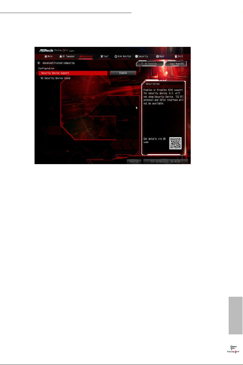
4.6.7 Trusted Computing
Security Device Support
Enable or disable BIOS support for security device.
Fatal1ty B250M Performance Series
63
English
Page 71

4.7 Tools
UEFI Tech Service
Contact ASRock Tech Service if you are having trouble with your PC. Please setup
network conguration before using UEFI Tech Service.
Easy Driver Installer
For users that don’t have an optical disk drive to install the drivers from our support
CD, Easy Driver Installer is a handy tool in the UEFI that installs the LAN driver
to your system via an USB storage device, then downloads and installs the other
required drivers automatically.
English
64
Page 72
Fatal1ty B250M Performance Series
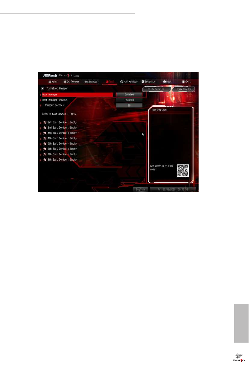
Boot Manager
Boot Manager is specically designed for the dual OS platform/multi-OS platform
users to easily customize and manage the boot menu.
*Please connect more than one boot devices to use this tool.
Boot Manager
Enable/disable the Boot Manager.
Boot Manager Timeout
Enable/disable the Boot Manager Timeout.
Timeout Seconds
Congure the number of seconds to wait for the Boot Manager.
Instant Flash
Save UEFI les in your USB storage device and run Instant Flash to update your
UEFI.
Internet Flash - DHCP (Auto IP), Auto
ASRock Internet Flash downloads and updates the latest UEFI rmware version
from our servers for you. Please setup network conguration before using Internet
Flash.
*For BIOS backup and recovery purpose, it is recommended to plug in your USB
pen drive before using this function.
English
65
Page 73

Network Conguration
Use this to congure internet connection settings for Internet Flash.
Internet Setting
Enable or disable sound eects in the setup utility.
UEFI Download Server
Select a server to download the UEFI rmware.
English
66
Page 74

Fatal1ty B250M Performance Series
4.8 Hardware Health Event Monitoring Screen
is section allows you to monitor the status of the hardware on your system,
including the parameters of the CPU temperature, motherboard temperature, fan
speed and voltage.
Fan-Tastic Tuning
Select a fan mode for CPU Fan, or choose Customize to set 5 CPU temperatures and
assign a respective fan speed for each temperature.
CPU Fan 1 & 2 Setting
Select a fan mode for CPU Fan 1 & 2, or choose Customize to set 5 CPU
temperatures and assign a respective fan speed for each temperature.
Chassis Fan 1 Setting
Select a fan mode for Chassis Fan 1, or choose Customize to set 5 CPU temperatures
and assign a respective fan speed for each temperature.
Chassis Fan 1 Temp Source
Select a fan temperature source for Chassis Fan 1.
Chassis Fan 2 Setting
Select a fan mode for Chassis Fan 2, or choose Customize to set 5 CPU temperatures
and assign a respective fan speed for each temperature.
English
67
Page 75

Chassis Fan 2 Temp Source
Select a fan temperature source for Chassis Fan 2.
Over Temperature Protection
When Over Temperature Protection is enabled, the system automatically shuts down when
the motherboard is overheated.
Case Open Feature
Enable or disable Case Open Feature to detect whether the chassis cover has been
removed.
English
68
Page 76
Fatal1ty B250M Performance Series
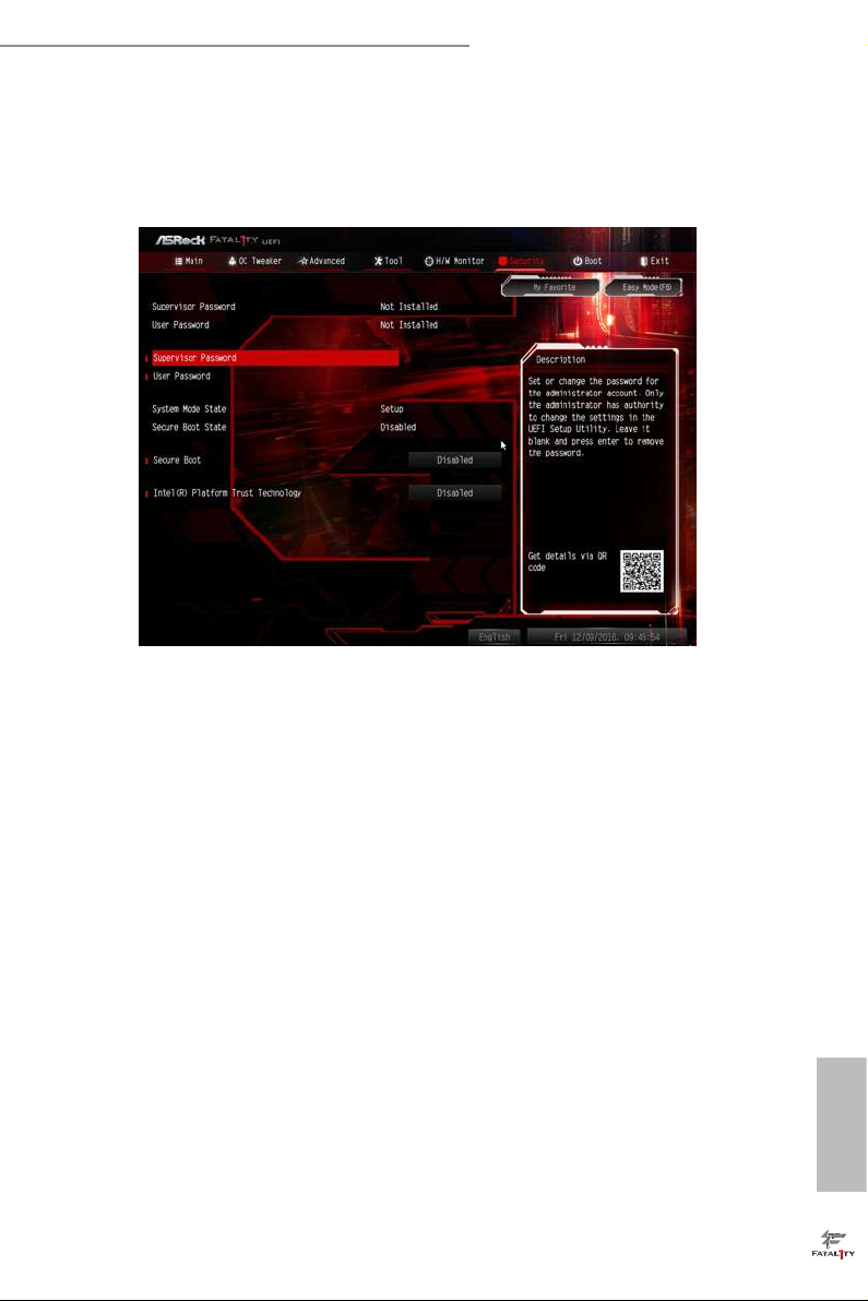
4.9 Security Screen
In this section you may set or change the supervisor/user password for the system.
You may also clear the user password.
Supervisor Password
Set or change the password for the administrator account. Only the administrator
has authority to change the settings in the UEFI Setup Utility. Leave it blank and
press enter to remove the password.
User Password
Set or change the password for the user account. Users are unable to change the
settings in the UEFI Setup Utility. Leave it blank and press enter to remove the
password.
Secure Boot
Use this item to enable or disable support for Windows 8.1 Secure Boot.
Intel(R) Platform Trust Technology
Enable/disable Intel PTT in ME. Disable this option to use discrete TPM Module.
English
69
Page 77

4.10 Boot Screen
is section displays the available devices on your system for you to congure the
boot settings and the boot priority.
Boot From Onboard LAN
Allow the system to be waked up by the onboard LAN.
Setup Prompt Timeout
Congure the number of seconds to wait for the setup hot key.
English
70
Bootup Num-Lock
Select whether Num Lock should be turned on or o when the system boots up.
Boot Beep
Select whether the Boot Beep should be turned on or o when the system boots up. Please
note that a buzzer is needed.
Full Screen Logo
Enable to display the boot logo or disable to show normal POST messages.
AddOn ROM Display
Enable AddOn ROM Display to see the AddOn ROM messages or congure the
AddOn ROM if you've enabled Full Screen Logo. Disable for faster boot speed.
Page 78

Fatal1ty B250M Performance Series
Boot Failure Guard Message
If the computer fails to boot for a number of times the system automatically restores
the default settings.
71
English
Page 79

CSM (Compatibility Support Module)
CSM
Enable to launch the Compatibility Support Module. Please do not disable unless
you’re running a WHCK test. If you are using Windows 8.1 64-bit and all of your
devices support UEFI, you may also disable CSM for faster boot speed.
Launch PXE OpROM Policy
Select UEFI only to run those that support UEFI option ROM only. Select Legacy
only to run those that support legacy option ROM only. Select Do not launch to not
execute both legacy and UEFI option ROM.
English
72
Launch Storage OpROM Policy
Select UEFI only to run those that support UEFI option ROM only. Select Legacy
only to run those that support legacy option ROM only. Select Do not launch to not
execute both legacy and UEFI option ROM.
Launch Video OpROM Policy
Select UEFI only to run those that support UEFI option ROM only. Select Legacy
only to run those that support legacy option ROM only. Select Do not launch to not
execute both legacy and UEFI option ROM.
Page 80

Fatal1ty B250M Performance Series
4.11 Exit Screen
Save Changes and Exit
When you select this option the following message, “Save conguration changes
and exit setup?” will pop out. Select [OK] to save changes and exit the UEFI SETUP
UTILITY.
Discard Changes and Exit
When you select this option the following message, “Discard changes and exit
setup?” will pop out. Select [OK] to exit the UEFI SETUP UTILITY without saving
any changes.
Discard Changes
When you select this option the following message, “Discard changes?” will pop
out. Select [OK] to discard all changes.
Load UEFI Defaults
Load UEFI default values for a ll options. e F9 key can be used for this operation.
Launch EFI Shell from lesystem device
Copy shellx64.e to the root directory to launch EFI Shell.
English
73
Page 81

Contact Information
If you need to contact ASRock or want to know more about ASRock, you’re welcome
to visit ASRock’s website at http://ww w.asrock.com; or you may contact your dealer
for further information. For technical questions, please submit a support request
form at http://www.asrock.com/support/tsd.asp
ASRock Incorporation
2F., No.37, Sec. 2, Jhongyang S. Rd., Beitou District,
Taipei City 112, Taiwan (R.O.C.)
ASRock EUROPE B.V.
Bijsterhuizen 11-11
6546 AR Nijmegen
e Netherlands
Phone: +31-24-345-44-33
Fax: +31-24-345-44-38
ASRock America, Inc.
13848 Magnolia Ave, Chino, CA91710
U.S.A.
Phone: +1-909-590-8308
English
74
Fax: +1-909-590-1026
 Loading...