

Page 1

Page 2

Version 1.0
Published June 2020
is device complies with Part 15 of the FCC Rules. Operation is subject to the following
two conditions:
(1) this device may not cause harmful interference, and
(2) this device must accept any interference received, including interference that
may cause undesired operation.
CALIFORNIA, USA ONLY
e Lithium battery adopted on this motherboard contains Perchlorate, a toxic substance
controlled in Perchlorate Best Management Practices (BMP) regulations passed by the
California Legislature. When you discard the Lithium battery in California, USA, please
follow the related regulations in advance.
“Perchlorate Material-special handling may apply, see ww w.dtsc.ca.gov/hazardouswaste/
perchlorate”
Page 3

AUSTRALIA ONLY
Our goods come with guarantees that cannot be excluded under the Australian Consumer
Law. You are entitled to a replacement or refund for a major failure and compensation for
any other reasonably foreseeable loss or damage caused by our goods. You are also entitled
to have the goods repaired or replaced if the goods fail to be of acceptable quality and the
failure does not amount to a major failure.
e terms HDMI™ and HDMI High-Denition Multimedia Interface, and the HDMI
logo are trademarks or registered trademarks of HDMI Licensing LLC in the United
States and other countries.
Page 4

Contents
Chapter 1 Introduction 1
1.1 Package Contents 1
1.2 Specications 2
Chapter 2 Product Overview 4
2.1 Front View 4
2.2 Rear View 5
1.3 Motherboard Layout 6
Chapter 3 Hardware Installation 13
3.1 Begin Installation 13
3.2 Installing the CPU 14
3.3 Installing the CPU Fan and Heatsink 16
3.4 Installing Memory Modules (SO-DIMM) 17
3.5 Installing the WiFi Module 18
3.6 Installing the M.2 SSD (Type 2280) 19
3.7 Installing the 2.5-inch HDD/SSD 20
3.8 Complete 22
3.9 Installing the VESA Bracket (Optional) 23
3.10 Installing the WiFi Antennas (Optional) 25
Chapter 4 Software and Utilities Operation 27
4.1 Installing Drivers 27
Page 5

Chapter 5 UEFI SETUP UTILITY 28
5.1 Introduction 28
5.2 EZ Mode 29
5.3 Advanced Mode 30
5.3.1 UEFI Menu Bar 30
5.3.2 Navigation Keys 31
5.4 Main Screen 32
5.5 OC Tweaker Screen 33
5.6 Advanced Screen 41
5.6.1 CPU Conguration 42
5.6.2 Chipset Conguration 44
5.6.3 Storage Conguration 47
5.6.4 ACPI Conguration 48
5.6.5 USB Conguration 49
5.6.6 Trusted Computing 50
5.7 Tools 52
5.8 Hardware Health Event Monitoring Screen 54
5.9 Security Screen 55
5.10 Boot Screen 56
Page 6

DeskMini H470 series
Chapter 1 Introduction
ank you for purchasing DeskMini H470 series barebone system. In this
documentation, Chapter 1 and 2 contains the introduction of the barebone system
and step-by-step installation guides. Chapter 3 contains the guide of hardware
installation. Chapter 4 contains the operation guide of the soware and utilities.
Chapter 5 contains the conguration guide of the BIOS setup.
Becau se the barebone system specications and the BIOS soware might be updated, the
content of this documentation will be subject to change without notice.
1.1 Package Contents
DeskMini H470 series Barebone System with:
•
DeskMini H470 series Chassis
Motherboard (pre-installed)
*e barebone system does not include memory, hard drive, WiFi module and M.2
SSD.
120W/19V Power Adapter & Power Cord (Optional)
•
SATA Cable (Optional)
•
Screws Package (HDD Screw x 6, M.2 Screw x 3pcs, Rubber Foot x 4pcs)
•
Support CD (Optional)
•
Quick Installation Guide (Optional)
•
*Package contents may vary based on local distribution.
If any items are missing or appear dam aged, contac t your authorized deal er.
English
Page 7

1.2 Specications
System
Model
Chassis
CPU
CPU cooling
Motherboard
Chipset
Graphics
Memory
Audio
DeskMini H470
•
1.92L (155 x 155 x 80mm)
•
Suppor ts 10th Gen Intel® CoreTM Processors (Socket 1200)
•
Supports Standard Intel Box Fan Coolers
•
H470M-STX
•
Intel® H470
•
Intel® UHD Graphics
•
Supports DDR4 2933MHz, 2 x SO-DIMM Slots, Max. 64GB
•
Realtek ALC233 Audio Codec
•
Intel Gigabit I219V LAN
•
1 x M.2 Socket (Key E), supports ty pe 2230 WiFi/BT module
•
and Intel® CNVi (Integrated WiFi/BT)
Power Button (with power LED & HDD LED)
•
1 x USB 3.2 Gen2 (Type-A), 1 x USB 3.2 Gen1 (Type-C), 1 x
•
Headphone/Headset Jack , 1 x MIC-In
1 x VGA , 1 x HDMI, 1 x DP, 4 x USB 3.2 Gen1 Type-A, 1 x
•
USB 3.2 Gen1 Type-C , 1 x LAN, 1 x DC-In Jack
English
LAN
Expansion
Slot
Front I/O
Rear I/O
2 3
Page 8

Storage
Onboard
Connectors
Drive Bays
DeskMini H470 series
2 x SATA3 6.0 Gb/s Connectors, support RAID (RAID 0,
•
RAID 1, Intel Rapid Storage Technology 17), NCQ, AHCI and
Hot Plug
1 x Ultra M.2 Socket, support type 2280 M.2 SATA3 6.0 Gb/s
•
module and M.2 PCI Express module up to Gen3 x4 (32 Gb/s)*
* Supports Intel® OptaneTM Tech nolo gy
* Supports NVMe SSD as boot disks
2 x CPU Fan Connectors (2 x 4-pin)
•
1 x Internal Speaker Header
•
1 x Front Panel Header
•
1 x USB 2.0 Header (Supports 2 USB 2.0 ports) (Supports ESD
•
Protection)
1 x Audio Header
•
2 x 2.5" HDD or SSD
•
Power
Adapter
Operation
Tem p.
Please realiz e that the re is a certain r isk involved with o verclocking, including adjusting
the setting in the BIOS, applying Untied Overclocking Technolog y, or using third-party
overclocking to ols. O verclocking may aect your system’s stability, or even c ause damage to
the components and devices of your system. It should be don e at your ow n risk and expense.
We are not responsibl e for possible damage caused by overclo cking.
120W/19V Power Adapter
•
0~35°C
•
English
Page 9
Chapter 2 Product Overview
is chapter provides diagrams showing the location of important components of
the DeskMini H470 Barebone system series.
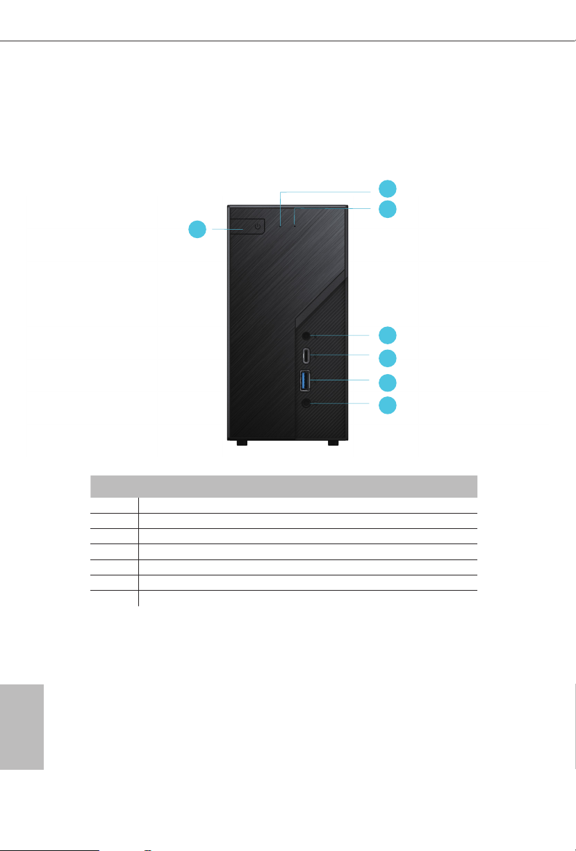
2.1 Front View
1
No. Description
1 Power Button
2 Power LED
3 HDD LED
4 MIC-In
5 USB 3.2 Gen1 Type-C Port
6 USB 3.2 Gen2 Type-A Port
7 Headphone/Headset
2
3
4
5
6
7
English
4 5
Page 10
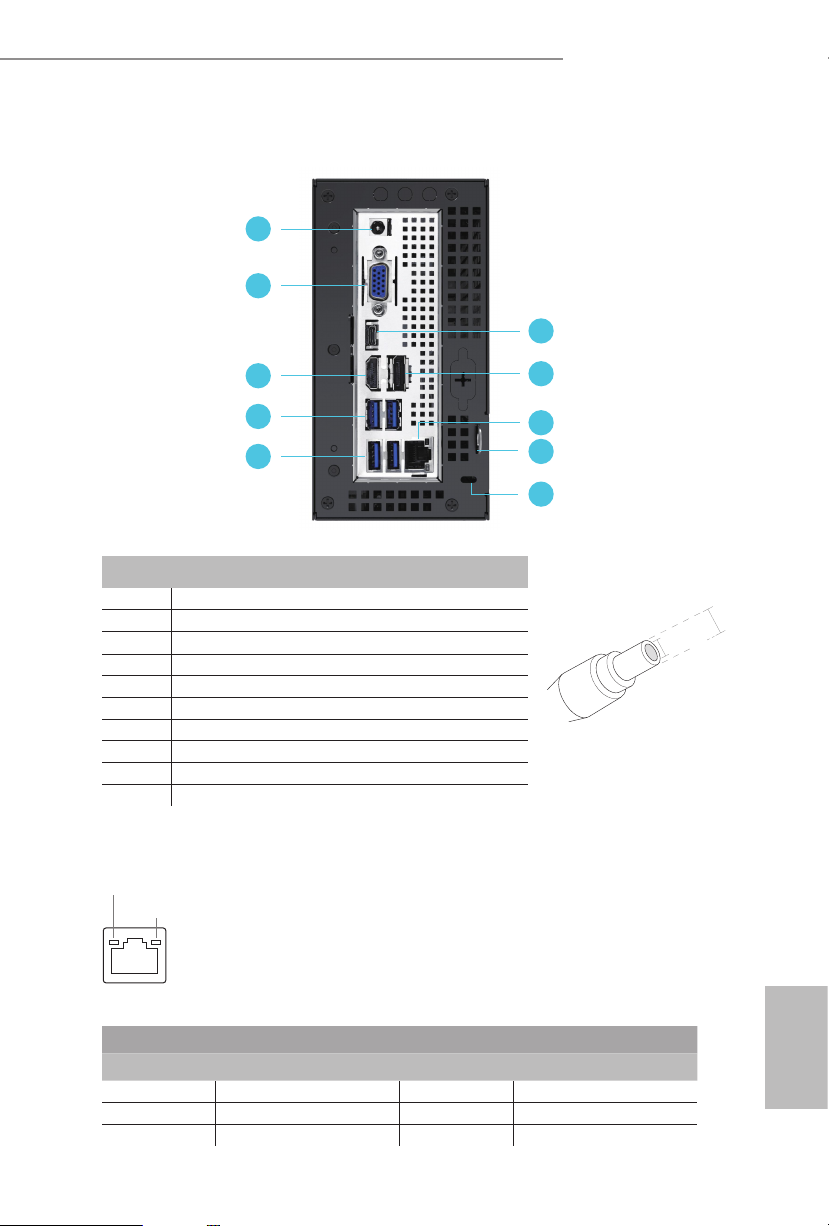
2.2 Rear View
DeskMini H470 series
1
2
6
3
4
5
7
8
9
10
No. Description
1 DC Jack
2 D-Sub Port
3 HDMI Port
4 USB 3.2 Gen1 Type-A Ports
5 USB 3.2 Gen1 Type-A Ports
6 USB 3.2 Gen1 Type-C Port ( USB-C / DP Alt mode )
7 DisplayPort 1.4
8 LAN RJ-45 Port**
9 Key Lock
10 Kensington Lock
** ere are two LEDs on the LAN port. Please refer to the table below for the LAN port LED indications.
ACT/LINK LED
SPEED LED
(Supports 19V DC Power Adapters)
*
*Specication for DC plug
5.5 mm
2.5 mm
LAN Por t
Activity / Link LED Speed LED
Status Description Status Description
O No Link O 10Mbps connection
Blinking Data Activity Orange 100Mbps connection
On Link Green 1Gbps connection
English
Page 11
Top:
RJ-45
Ro HS
1
5
USB_8_9
1
3
HDLED RESET
PLED PWRBTN
PANEL1
1
Mic In
USB 3.2 Gen1
USB_2
USB 3.2 Gen1
USB_3
USB 3.2 Gen1
USB_1
Headphone
/ Headset
VGA1
8
7
DDR 4_A1DDR 4_A1
DDR 4_B1
DC Jack
SPEAKER1
1
Sup er
I/O
BIOS
ROM
M2_ WIF I
M2_ 1
M2_WIFI_CT1
M2_1_CT1
CPU_FAN1
CPU_FAN2
1
AUDIO3
H4 70M - STX
1
CLRMOS1
6
2
CMOS
Battery
4
DP_ 1
HDM I1
USB 3.2 Gen1
T: USB_6
B: USB_7
USB 3.2 Gen1
T: USB_4
B: USB_5
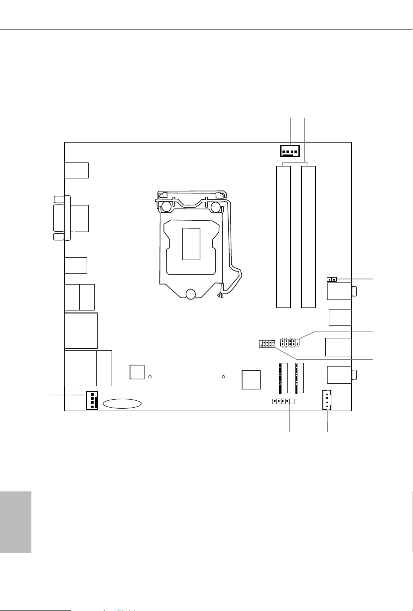
1.3 Motherboard Layout
English
6 7
Page 12
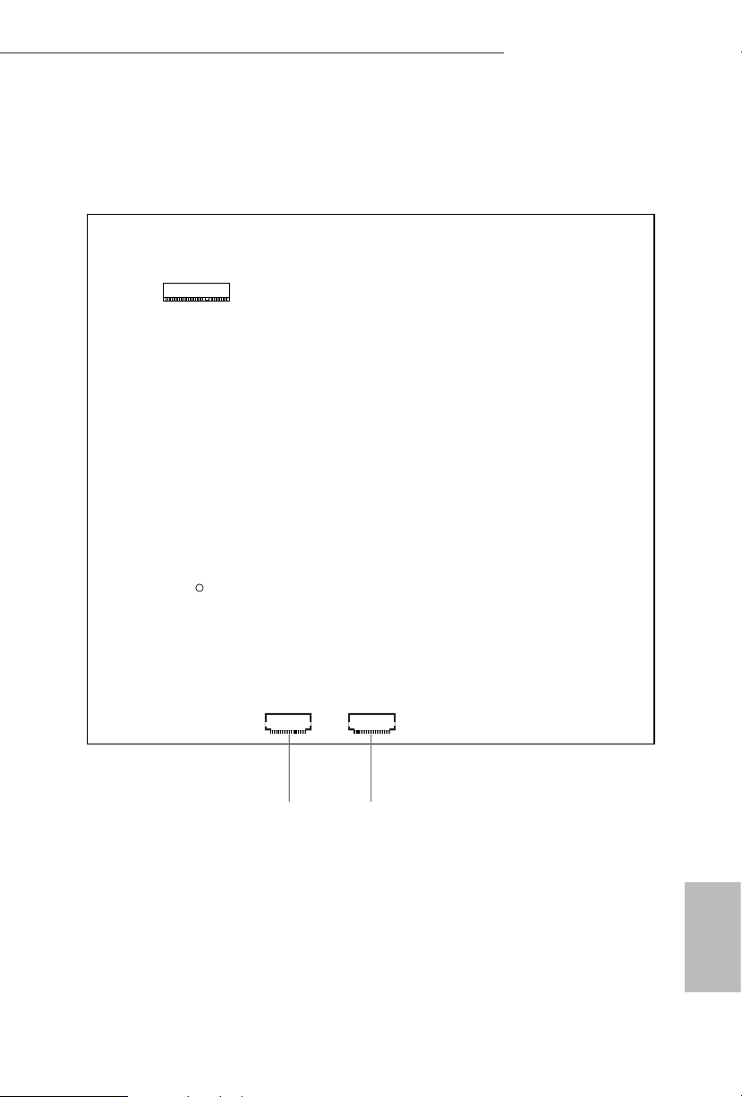
Bottom View
SATA3 SATA3
M2_2
DeskMini H470 series
910
English
Page 13

No. Description
1 CPU Fan Connector (CPU_FAN1)
2 2 x 260-pin DDR4 SO-DIMM Slots (DDR4_A1, DDR4_B1)
3 Clear CMOS Jumper (CLR MOS1)
4 System Panel Header (PANEL1)
5 USB 2.0 Header (USB_8_9)
6 MONO Speaker Header (SPEAKER1)
7 Audio Header (AUDIO3)
8 CPU Fan Connector (CPU_FAN2)
9 SATA3 Connector (SATA2)
10 SATA3 Connector (SATA1)
English
8 9
Page 14
DeskMini H470 series
Jumpers Setup
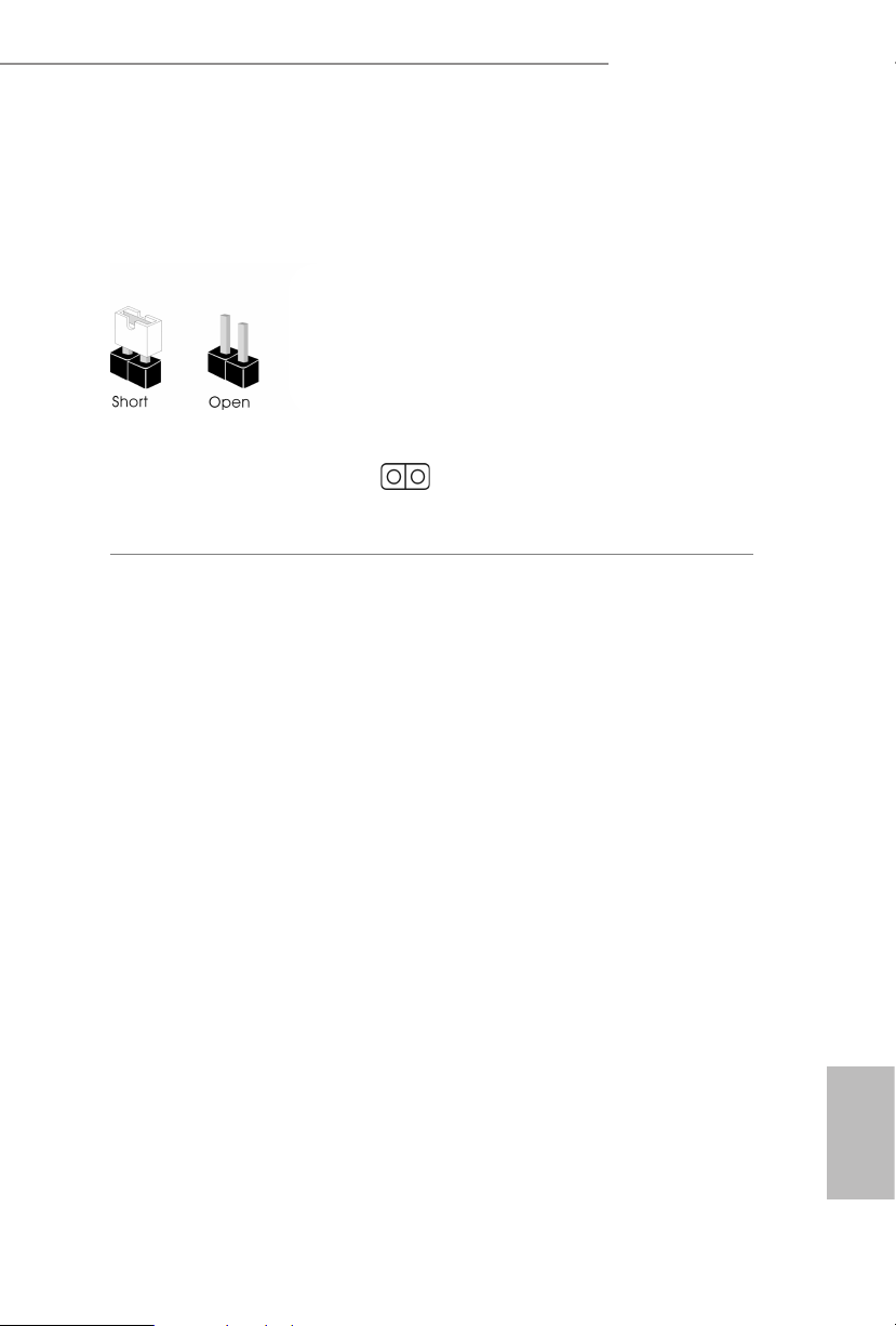
e illustration shows how jumpers are setup. When the jumper cap is placed on
the pins, the jumper is “Short”. If no jumper cap is placed on the pins, the jumper is
“O pen”.
Clear CMOS Jumper
(CLRCMO S1)
(see p.6, No. 3)
CLRCMOS1 allows you to clear the data in CMOS. e data in CMOS includes
system setup information such as system password, date, time, and system setup
parameters. To clear and reset the system parameters to default setup, please
turn o the computer and unplug the power cord, then use a jumper cap to short
the pins on CLRCMOS1 for 3 seconds. Please remember to remove the jumper
cap aer clearing the CMOS. If you need to clear the CMOS when you just nish
updating the BIOS, you must boot up the system rst, and then shut it down
before you do the clear-CMOS action.
2-pin Jumper
Short: Clear CMOS
Open: Default
English
Page 15
Onboard Headers and Connectors
1
Onboard headers and connectors are NOT jump ers. Do NOT place jumper caps over these
heade rs and connectors. Placing jumper caps over the headers and connector s will cause
permanent damage to the motherboard.
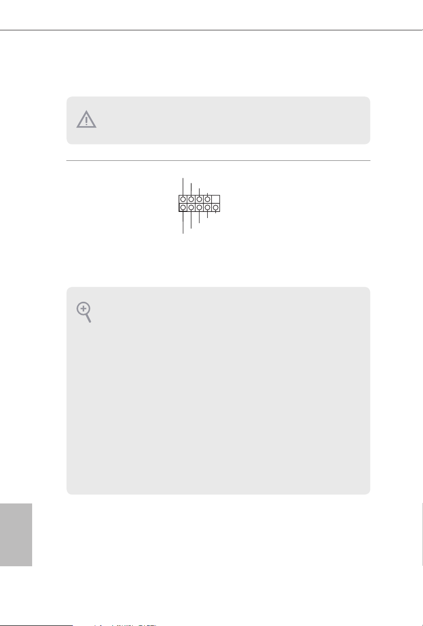
System Panel Header
(9-pi n PANEL1)
(see p.6, No. 4)
PWRBTN (Power Button):
Connec t to the power button on the ch assi s front panel. You may congure the way to tur n
o your system using the power button.
RESET (Reset B utton):
Connec t to the reset button on the ch assi s front panel. P ress the reset button to re start the
computer if the computer f reezes and fails to per form a normal restar t.
PLED (Syste m Power LED):
Connec t to the power status indicator on the chas sis front panel. e LED i s on when the
system is operating. e LED keeps blinking when the system is in S1/S3 sleep state. e
LED is o when the system is in S4 slee p state or powered o (S5).
HDLED (Ha rd Drive Activity LED):
Connec t to the hard drive ac tivity LED on the chassis front panel. e LED is on when the
hard drive is reading or wr iting data.
e front panel de sign may dier by chassis. A front panel module mainly consists of powe r
button, reset button , power LED, hard dr ive activity LED, speaker and etc. When connecting your ch assi s front panel module to thi s header, make sure the wire a ssignments and the
pin assignments are matched correctly.
PLED+
PLED-
HDLED-
HDLED+
PWRBTN#
GND
RESET#
GND
GND
Connect the power
button, reset button and
system status indicator on
the chassis to this header
according to the pin
assignments below. Note
the positive and negative
pins before connecting
the cables.
English
10 11
Page 16
DeskMini H470 series
Front_R+
1
FAN_SPEED_CONTROL
FA
1
2
3
4
DUMMY
GND
GND
P+
P-
USB_PWR
P+
P-
USB_PWR
1
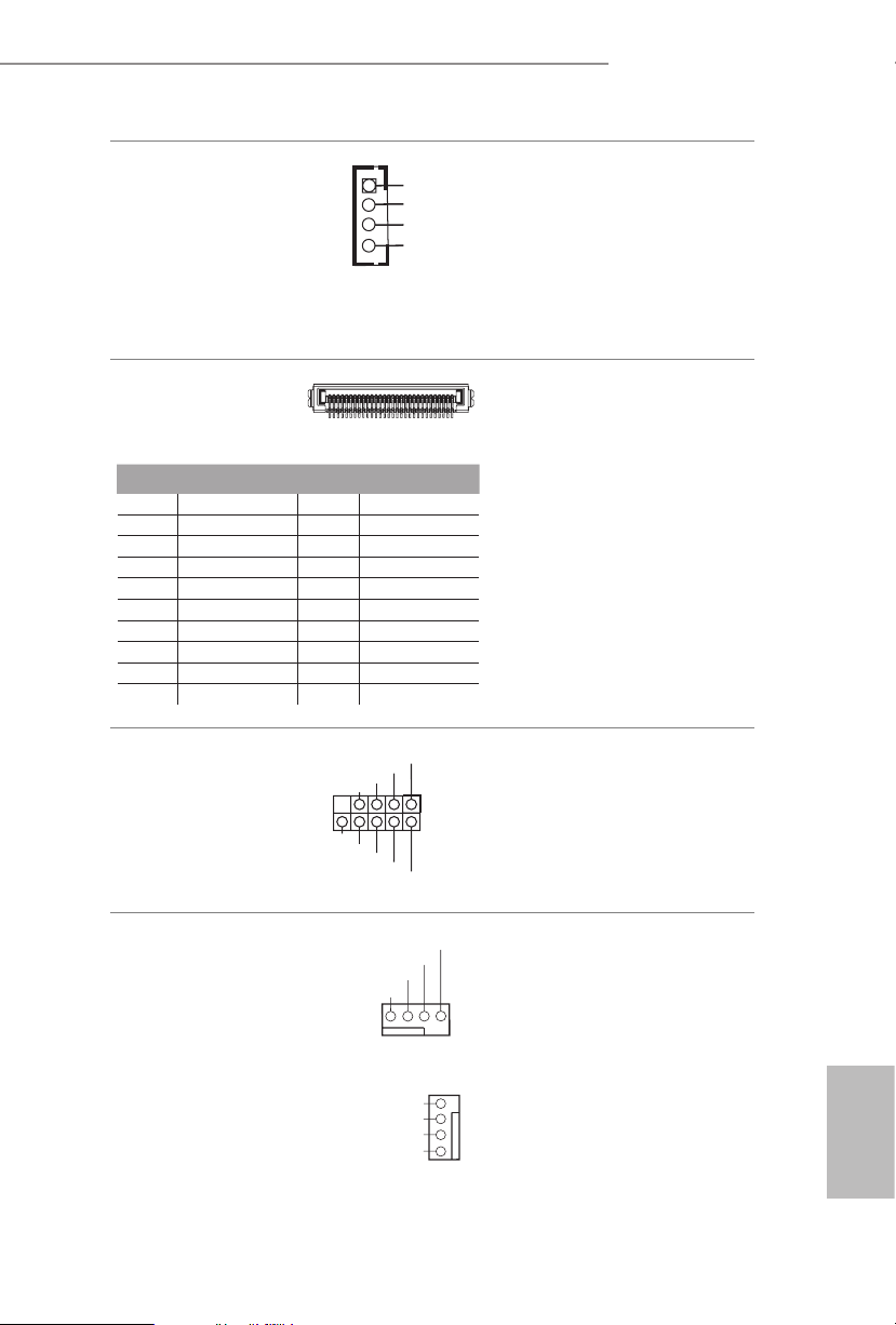
MONO Speaker Header
(4-p i n SPEAKER1)
(see p.6, No. 6)
Front_L-
Front_L+
Front_R-
Serial ATA3 Connectors
(see p.7, No. 9 and 10)
1
PIN Signal Name PIN Signal Name
1 GND 11 N /A
2 LVDS _TX+ 12 5V
3 LVDS _TX- 13 5V
4 GND 14 5V
5 GND 15 5V
6 LV DS_R X- 16 5V
7 LVDS _ R X+ 17 N/A
8 GND 18 GND
9 GND 19 GND
10 GND 20 GND
USB 2.0 Header
(9-pin USB_8_9)
(see p.6, No. 5)
Please connect the chassis
speaker to this header.
ese two SATA3
20
connectors support SATA
data cables for internal
storage devices with up to
6.0 Gb/s data transfer rate.
*e SATA3 connectors
support 2.5-inch hard
drive (+5V) and do not
support 3.5-inch hard
drive (+12V)
ere is one header on
this motherboard. is
USB 2.0 header can
support two ports.
CPU Fan Connectors
(4-pin CPU_FAN1)
(see p.6, No. 1)
(4-pin CPU_FAN2)
(see p.6, No. 8)
CPU_FAN_SPEED
FAN_VOLTAGE
GND
1 2 3 4
N_SPEED_CONTROL
FAN_SPEED
FAN_VOLTAGE
GND
is motherboard
provides two 4-Pin CPU
fan (Quiet Fan)
connectors. If you plan to
connect a 3-Pin CPU fan,
please connect it to Pin
1-3.
English
Page 17

Audio Header
(5-pin AUDIO3)
(see p.6, No. 7)
1
GND
Audio-L
Jack detect
Audio-R
is Audio header allows you to
connect the audio cable for head-
phone.
English
12 13
Page 18
Chapter 3 Hardware Installation
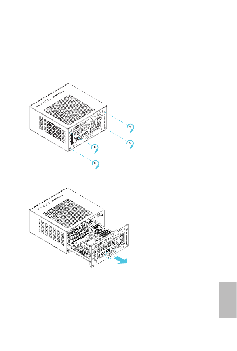
3.1 Begin Installation
1. Unscrew the four screws of the back panel.
2. Pull out the motherboard tray while holding the handle .
DeskMini H470 series
English
Page 19
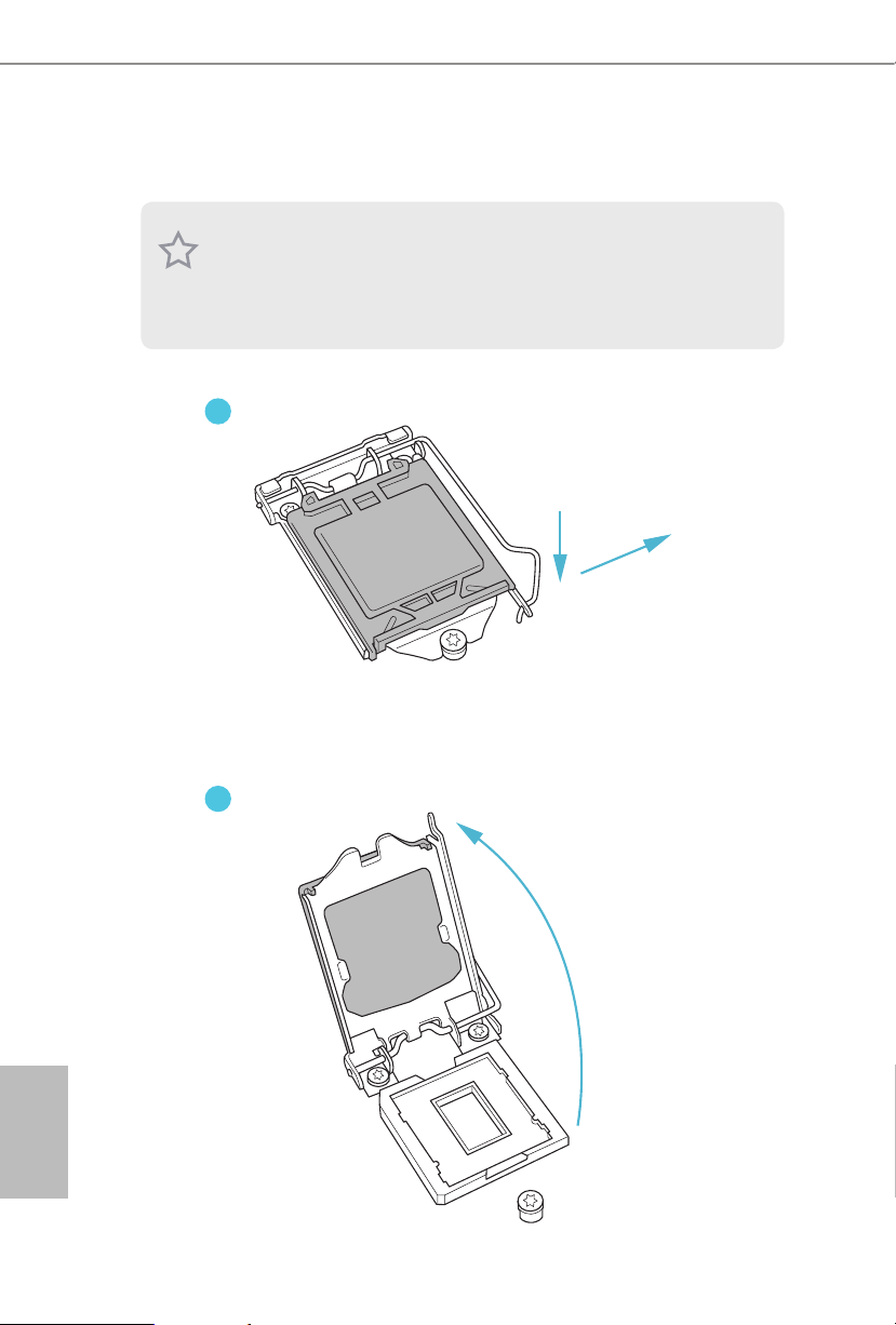
3.2 Installing the CPU
1
1. Before you insert the 1200-Pin CPU into the socke t, please check if the Pn P cap is on the
socket, if the CPU surface is unclean, or if there are any bent pins in the sock et. Do not
force to in sert the CPU into the socket if above situation is found . Otherwise, the CPU
will be seriously damaged.
2. Unplug all power c ables before in stalling the CPU.
English
A
B
2
14 15
Page 20

DeskMini H470 series
3
5
4
English
Page 21

3.3 Installing the CPU Fan and Heatsink
DeskMini H470 series supports both Intel CPU Box Fan (65W) and third-party CPU fan
cooler. Please note that the DeskMini H470 series cha ssis has 52mm height limitation for
the CPU fan cooler.
1 2
CPU_FAN
English
16 17
Page 22

DeskMini H470 series
3.4 Installing Memory Modules (SO-DIMM)
is motherboard provides two 260-pin DDR4 (Double Data Rate 4) SO-DIMM
slots.
1. DeskMini H470 series requires DDR4 SO-DI MM.
2. For dual channel conguration , you always need to in stall identical (the same brand,
speed , size and chip-type) DDR4 SO-DIMM pairs.
1. It is not all owed to in stall a DDR, DDR2 or DDR 3 memor y module into a DDR4 slot;
otherwise , this motherboard and SO-DIMM may be damaged.
2. e SO-DIMM only ts in one correc t orientation . It will cause pe rmanent damage to
the motherboard and the SO-DIMM if you force the SO-DIMM into the sl ot at incorrect
orientation.
1
32
English
Page 23

3.5 Installing the WiFi Module
1. Insert the WiFi Module Card into the M.2 Slot for WiFi + BT Module.
2. Tighten the screw to secure the WiFi Module Card to the motherboard.
3. Attach the SMA Wi-Fi Antenna Cables to the WiFi Module.
English
18 19
Page 24

3.6 Installing the M.2 SSD (Type 2280)
DeskMini H470 series
1. Locate the M.2 slot on the motherboard
2. Carefully insert the M.2 SSD into the slot.
3. Tighten the screw to secure the M.2 SSD to the motherboard.
.
English
Page 25

3.7 Installing the 2.5-inch HDD/SSD
1. Place another HDD/SSD on the tray B shown in Step 1. en turn the motherboard
tray upside down and secure the HDD/SSD with the four screws.
*Removing the motherboard before installing the second HDD/SSD.
B
A
2. Connect the SATA Data and Power Cable to the HDD/SSD.
3. Connect the other end of the SATA Cables to the SATA Connectors on the
motherboard.
English
20 21
Page 26

DeskMini H470 series
4. Place another HDD/SSD on the tray B shown in Step 1.
en turn the motherboard tray upside down and secure the HDD/SSD with the four
screws.
*Removing the motherboard before installing the second HDD/SSD.
5. Connect the SATA Data and Power Cable to the HDD/SSD.
6. Connect the other end of the SATA Cables to the SATA Connectors on the motherboard.
English
Page 27

3.8 Complete
1. Connect the power button cable to the System Panel Header on the motherboard.
PANEL1
2. Align the motherboard tray with the two sliding tracks on the chassis while sliding it
back to the chassis.
Sliding Track
3. en refasten the four screws that you removed earlier.
English
22 23
Page 28

DeskMini H470 series
3.9 Installing the VESA Bracket (Optional)
1. Secure the VESA Bracket to the right side panel of the DeskMini H470 series by using
the four screws.
2. Attach the other VESA Bracket to the rear of a compatible display using the four
screws.
*Choose mounting holes depending on the mounting hole pattern of your LCD screen
(75 mm × 75 mm or 100 mm × 100 mm).
3. Mount the DeskMini H470 series by turning it counterclockwise.
B
A
English
Page 29

4. Complete.
English
24 25
Page 30

DeskMini H470 series
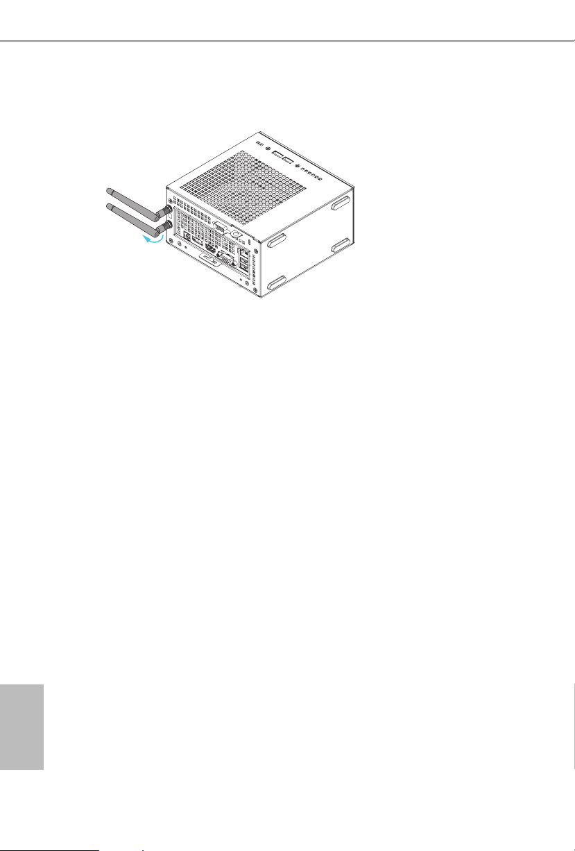
3.10 Installing the WiFi Antennas (Optional)
1. Insert the Wi-Fi Antenna Connectors to the antenna ports on the rear panel of the
DeskMini H470 series
*Please make sure to align the at surface of Wi-Fi Antenna Connectors with the at
side of holes when inserting the connectors.
2. Fasten the screw nuts to secure the antenna connectors.
3. Connect the two WiFi 2.4/5 GHz Antennas to the antenna connectors. Turn the
antenna clockwise until it is securely connected.
English
Page 31
4. Set the WiFi 2.4/5 GHz Antenna at 90-degree angle.
*You may need to adjust the direction of the antenna for a stronger signal.
English
26 27
Page 32

DeskMini H470 series
Chapter 4 Software and Utilities Operation
4.1 Installing Drivers
e Support CD that comes with the motherboard contains necessary drivers and
useful utilities that enhance the motherboard’s features.
Running The Support CD
To begin using the support CD, insert the CD into your CD-ROM drive. e CD
automatically displays the Main Menu if “AUTORUN” is enabled in your computer.
If the Main Menu does not appear automatically, locate and double click on the le
“ASRSETUP.EXE” in the Support CD to display the menu.
Drivers Menu
e drivers compatible to your system will be auto-detected and listed on the
support CD driver page. Please click Install All or follow the order from top to
bottom to install those required drivers. erefore, the drivers you install can work
properly.
Utilities Menu
e Utilities Menu shows the application soware that the motherboard supports.
Click on a specic item then follow the installation wizard to install it.
English
Page 33

Chapter 5 UEFI SETUP UTILITY
5.1 Introduction
is section explains how to use the UEFI SETUP UTILITY to congure your
system. You may run the UEFI SETUP UTILITY by pressing <F2> or <Del> right
aer you power on the computer, other wise, the Power-On-Self-Test (POST) will
continue with its test routines. If you wish to enter the UEFI SETUP UTILITY aer
POST, restart the system by pressing <Ctl> + <Alt> + <Delete>, or by pressing the
reset button on the system chassis. You may also restart by turning the system o
and then back on.
Becau se the UEFI soware is constantly being upd ated, the following UEFI setup screens
and descriptions are for reference pur pose only, and they may not exactly match what you
see on your screen.
English
28 29
Page 34

DeskMini H470 series
5.2 EZ Mode
e EZ Mode screen appears when you enter the BIOS setup program by default. EZ
mode is a dashboard which contains multiple readings of the system’s current status.
You can check the most crucial information of your system, such as CPU speed,
DRAM frequency, SATA information, fan speed, etc.
Press <F6> or click the "Advanced Mode" button at the upper right corner of the
screen to switch to "Advanced Mode" for more options.
No. Function
Help
1
Load UEFI Defaults
2
Save Changes and Exit
3
Discard Changes
4
Change Language
5
Switch to Advanced Mode
6
English
Page 35

5.3 Advanced Mode
e Advanced Mode provides more options to congure the BIOS settings. Refer to
the following sections for the detailed congurations.
To access the EZ Mode, press <F6> or click the "EZ Mode" button at the upper right
corner of the screen.
5.3.1 UEFI Menu Bar
e top of the screen has a menu bar with the following selections:
Main
OC Tweaker
Advanced
Tool
H/W Monitor
Security
Boot
Exit
For setting system time/date information
For overclocking congurations
For advanced system congurations
Useful tools
Displays current hardware status
For security settings
For conguring boot settings and boot priority
Exit the current screen or the UEFI Setup Utility
English
30 31
Page 36

DeskMini H470 series
5.3.2 Navigation Keys
Use < > key or < > key to choose among the selections on the menu bar, and
use < > key or < > key to move the cursor up or down to select items, then
press <Enter> to get into the sub screen. You can also use the mouse to click your
required item.
Please check the following table for the descriptions of each navigation key.
Navigation Key(s) Description
+ / -
<Tab>
<PGUP>
<PGDN>
<HOME>
<END>
<F1>
<F5>
<F7>
<F9>
<F10>
<F12>
<ESC>
To change option for the selected items
Switch to next function
Go to the previous page
Go to the next page
Go to the top of the screen
Go to the bottom of the screen
To display the General Help Screen
Add / Remove Favorite
Discard changes and exit the SETUP UTILITY
Load optimal default values for all the settings
Save changes and exit the SETUP UTILITY
Print screen
Jump to the Exit Screen or exit the current screen
English
Page 37

5.4 Main Screen
When you enter the UEFI SETUP UTILITY, the Main screen will appear and
display the system overview.
e availability and location of BIOS settings can be dierent for dierent models
and BIOS versions .
My Favorite
Display your collection of BIOS items. Press F5 to add/remove your favorite items.
English
32 33
Page 38

5.5 OC Tweaker Screen
In the OC Tweaker screen, you can set up overclocking features.
DeskMini H470 series
Becau se the UEFI soware is constantly being upd ated, the following UEFI setup
screens and de scriptions are for refe rence purpose only, and they may not exactly
match what you see on your scre en.
Base Frequency Boost
Via ASRock BFB (Boost Frequency Boost) Technology, users may install their non K series
CPUs to ASRock ’s 400 series motherboards (even non Z models) and enjoy the base
frequency boost with the hidden power of processors immediately.
CPU Conguration
AVX Ratio Oset
AVX Ratio Oset species a negative oset from the CPU Ratio for AVX workloads.
AVX is a more stressful work load that lower the AVX ratio to ensure maximum
possible ratio for SSE workloads.
BCLK Spread Spectrum
Enable BCLK Spread Spectrum to reduce electromagnetic interference for passing
EMI tests. Disable to achieve higher clock speeds when overclocking.
English
Page 39

BCLK Aware Adaptive Voltage
BCLK Aware Adaptive Voltage enable/disable. When enabled, pcode will be aware
of the BCLK frequency when calculating the CPU V/F curves. is is ideal for
BCLK OC to avoid high voltage overrides.
Boot Performance Mode
Select the performance state that the BIOS will set before OS hando.
FCLK Frequency
Congure the FCLK Frequency.
Ring to Core Ratio Oset
Disable Ring to Core Ratio Oset so the ring and core can run at the same fre-
quency.
Intel SpeedStep Technology
Intel SpeedStep technology allows processors to switch between multiple frequen-
cies and voltage points for better power saving and heat dissipation.
Intel Turbo Boost Technology
Intel Turbo Boost Technolog y enables the processor to run above its base operating
frequency when the operating system requests the highest performance state.
Intel Speed Shift Technology
Enable/Disable Intel Speed Shi Technology support. Enabling will expose the
CPPC v2 interface to allow for hardware controlled P-sates.
Intel Thermal Velocity Boost Voltage Optimizations
is service controls thermal based voltage optimizations for processors that
implment the Intel ermal Velocity Boost (TVB) feature.
Dual Tau Boost
Enable Dual Tau Boost feature. is is only applicable for CMLS 35W/65W/125W
skus.is item is only supported with processors with Cong TDP support.
English
Long Duration Power Limit
Congure Package Power Limit 1 in watts. When the limit is exceeded, the CPU
ratio will be lowered aer a period of time. A lower limit can protect the CPU and
save power, while a higher limit may improve performance.
34 35
Page 40

DeskMini H470 series
Long Duration Maintained
Congure the period of time until the CPU ratio is lowered when the Long
Duration Power Limit is exceeded.
Short Duration Power Limit
Congure Package Power Limit 2 in watts. When the limit is exceeded, the CPU
ratio will be lowered immediately. A lower limit can protect the CPU and save
power, while a higher limit may improve performance.
CPU Core Current Limit
Congure the current limit of the CPU core. A lower limit can protect the CPU and
save power, while a higher limit may improve performance.
GT Current Limit
Congure the current limit of the GT slice. A lower limit can protect the CPU and
save power, while a higher limit may improve performance.
DRAM Conguration
Memory Information
Allows users to browse the serial presence detect (SPD) and Intel extreme memory prole
(XMP) for DDR4 modules.
DRAM Timing Conguration
Load XMP Setting
Load XMP settings to overclock the memory and perform beyond standard specications.
DRAM Frequency
If [Auto] is selected, the motherboard will detect the memory module(s) inserted
and assign the appropriate frequency automatically.
Primary Timing
CAS# Latency (tCL)
e time between sending a column address to the memory and the beginning of the data
in response.
RAS# to CAS# Delay and Row Precharge (tRCDtRP)
RAS# to CAS# Delay : e number of clock cycles required between the opening of a row
of memory and accessing columns within it.
Row Precharge: e number of clock cycles required between the issuing of the precharge
command and opening the next row.
English
Page 41

RAS# Active Time (tRAS)
e number of clock cycles required between a bank active command and issuing the
precharge command.
Command Rate (CR)
e delay between when a memor y chip is selected and when the rst active command can
be issued.
Secondary Timing
Write Recovery Time (tWR)
e amount of delay that must elapse aer the completion of a valid write operation,
before an active bank can be precharged.
Refresh Cycle Time (tRFC)
e number of clocks from a Refresh command until the rst Activate command to
the same rank.
RAS to RAS Delay (tRRD_L)
e number of clocks between two rows activated in dierent banks of the same
rank.
RAS to RAS Delay (tRRD_S)
e number of clocks between two rows activated in dierent banks of the same
rank.
Write to Read Delay (tWTR_L)
e number of clocks between the last valid write operation and the next read command to
the same interna l bank.
Write to Read Delay (tWTR_S)
e number of clocks between the last valid write operation and the next read command to
the same interna l bank.
Read to Precharge (tRTP)
English
e number of clocks that are inserted between a read command to a row pre-
charge command to the same rank.
Four Activate Window (tFAW)
e time window in which four activates are allowed the same rank.
36 37
Page 42

DeskMini H470 series
CAS Write Latency (tCWL)
Congure CAS Write Latency.
Third Timing
tREFI
Congure refresh cycles at an average periodic interval.
tCKE
Congure the period of time the DDR4 initiates a minimum of one refresh
command internally once it enters Self-Refresh mode.
Turn Around Timing
tRDRD_sg
Congure between module read to read delay.
tRDRD_dg
Congure between module read to read delay.
tRDRD_dr
Congure between module read to read delay.
tRDRD_dd
Congure between module read to read delay.
tRDWR_sg
Congure between module read to write delay.
tRDWR_dg
Congure between module read to write delay.
tRDWR_dr
Congure between module read to write delay.
tRDWR_dd
Congure between module read to write delay.
tWRRD_sg
Congure between module write to read delay.
English
Page 43

tWRRD_dg
Congure between module write to read delay.
tWRRD_dr
Congure between module write to read delay.
tWRRD_dd
Congure between module write to read delay.
tWRWR_sg
Congure between module write to write delay.
tWRWR_dg
Congure between module write to write delay.
tWRWR_dr
Congure between module write to write delay.
tWRWR_dd
Congure between module write to write delay.
Round Trip Timing
RTL Init Value
Congure round trip latency init value for round trip latency training.
IO-L Init Value
Congure IO latency init value for IO latency training.
RTL (CH A)
Congure round trip latency for channel A.
RTL (CH B)
Congure round trip latency for channel B.
IO-L (CH A)
English
Congure IO latency for channel A.
IO-L (CH B)
Congure IO latency for channel B.
38 39
Page 44

DeskMini H470 series
IO-L Oset (CH A)
Congure IO latency oset for channel A.
IO-L Oset (CH B)
Congure IO latency oset for channel B.
RFR Delay (CH A)
Congure RFR Delay for Channel A.
RFR Delay (CH B)
Congure RFR Delay for Channel B.
ODT Setting
ODT WR (A1)
Congure the memory on die termination resistors' WR for channel A.
ODT WR (B1)
Congure the memory on die termination resistors' WR for channel B.
ODT NOM (A1)
Use this to change ODT (CH A) Auto/Manual settings. e default is [Auto].
ODT NOM (B1)
Use this to change ODT (CH B) Auto/Manual settings. e default is [Auto].
ODT PARK (A1)
Congure the memory on die termination resistors' PARK for channel A.
ODT PARK (B1)
Congure the memory on die termination resistors' PARK for channel B.
Advanced Setting
ASRock Timing Optimization
Congure the fast path through the MRC.
Realtime Memory Timing
Congure the realtime memory timings.
[Enabled] e system will allow performing realtime memory timing changes aer
MRC_DONE.
English
Page 45

Command Tristate
Congure the Command Tristate Support.
Exit On Failure
Congure the Exit On Failure for MRC training steps.
Reset On Training Fail
Reset system if the MRC training fails.
MRC Fast Boot
Enable Memory Fast Boot to skip DRAM memory training for booting faster.
Voltage Conguration
CPU V/F Curve
Congure CPU Voltage/Frequency Cur ve.
Performance Mode
Select the performance state that the BIOS will set before OS hando.
Adapter Select
Select the adapter.
DRAM Voltage
Use this to congure DRAM Voltage. e default value is [Auto].
English
40 41
Page 46

DeskMini H470 series
5.6 Advanced Screen
In this section, you may set the congurations for the following items: CPU
Conguration, Chipset Conguration, Storage Conguration, ACPI Conguration,
USB Conguration and Trusted Computing.
Setting wrong values in this sec tion may cause the system to malfunction.
UEFI Conguration
UEFI Setup Style
Select the default mode when entering the UEFI setup utility.
Active Page on Entry
Select the default page when entering the UEFI setup utility.
Full HD UEFI
When [Auto] is selected, the resolution will be set to 1920 x 1080 if the monitor
supports Full HD resolution. If the monitor does not support Full HD resolution,
then the resolution will be set to 1024 x 768. When [Disable] is selected, the
resolution will be set to 1024 x 768 directly.
English
Page 47

5.6.1 CPU Conguration
Intel Hyper Threading Technology
Intel Hyper reading Technology allows multiple threads to run on each core, so
that the overall performance on threaded soware is improved.
Active Processor Cores
Select the number of cores to enable in each processor package.
CPU C States Support
Enable CPU C States Support for power saving. It is recommended to keep C3, C6
C7 and C10 all enabled for better power saving.
Enhanced Halt State (C1E)
Enable Enhanced Halt State (C1E) for lower power consumption.
CPU C3 State Support
Enable C3 deep sleep state for lower power consumption.
English
CPU C6 State Support
Enable C6 deep sleep state for lower power consumption.
CPU C7 State Support
Enable C7 deep sleep state for lower power consumption.
42 43
Page 48

DeskMini H470 series
CPU C10 State Support
Enable C10 deep sleep state for lower power consumption.
Package C State Support
Enable CPU, PCIe, Memor y, Graphics C State Support for power saving.
CFG Lock
is item allows you to disable or enable the CFG Lock.
CPU Thermal Throttling
Enable CPU internal thermal control mechanisms to keep the CPU from overheat-
ing.
Intel Virtualization Technology
Intel Virtualization Technology allows a platform to run multiple operating systems
and applications in independent partitions, so that one computer system can
function as multiple virtual systems.
Hardware Prefetcher
Automatically prefetch data and code for the processor. Enable for better
performance.
Adjacent Cache Line Prefetch
Automatically prefetch the subsequent cache line while retrieving the currently
requested cache line. Enable for better performance.
Software Guard Extensions (SGX)
Intel SGX is a set of new CPU instructions that can be used by applications to set
aside private regions of code and data.
English
Page 49

5.6.2 Chipset Conguration
Above 4G Decoding
Enable or disable 64bit capable Devices to be decoded in Above 4G Address Space
(only if the system supports 64 bit PCI decoding).
VT-d
Intel® Virtualization Technology for Directed I/O helps your virtual machine
monitor better utilize hardware by improving application compatibility and
reliability, and providing additional levels of manageability, security, isolation, and
I/O performance.
SR-IOV Support
If system has SR-IOV capable PCIe Devices, this option Enables or Disables Single
Root IO Virtualization Support.
DMI Link Speed
Congure DMI Slot Link Speed. Auto mode is optimizing for overclocking.
PCI Express Native Control
English
Select Enable for enhanced PCI Express power saving in OS.
PCIE ASPM Support
is option enables/disables the ASPM support for all CPU downstream devices.
44 45
Page 50

DeskMini H470 series
PCH PCIE ASPM Support
is option enables/disables the ASPM support for all PCH PCIE devices.
DMI ASPM Support
is option enables/disables the control of ASPM on CPU side of the DMI Link.
PCH DMI ASPM Support
is option enables/disables the ASPM support for all PCH DMI devices.
Share Memory
Congure the size of memory that is allocated to the integrated graphics processor when
the system boots up.
Inte(R) Ethernet Connection I219-V
Enable or disable the onboard network interface controller (Intel® I219V).
Onboard HD Audio
Enable/disable onboard HD audio. Set to Auto to enable onboard HD audio and
automatically disable it when a sound card is installed.
Internal Speaker
Enable/disable the internal speaker.
Onboard HDMI HD Audio
Enable audio for the onboard digital outputs.
Onboard WAN Device
Use this item to enable or disable the onboard WAN device.
WAN Radio
Enable/disable the WiFi module's connectivity.
Bluetooth
Enable/disable the Bluetooth connectivity.
Deep Sleep
Congure deep sleep mode for power saving when the computer is shut down.
English
Page 51

Restore on AC/Power Loss
Select the power state aer a power failure. If [Power O] is selected, the power will
remain o when the power recovers. If [Power On] is selected, the system will start
to boot up when the power recovers.
English
46 47
Page 52

5.6.3 Storage Conguration
SATA Controller(s)
Enable/disable the SATA controllers.
DeskMini H470 series
SATA Mode Selection
AHCI: Supports new features that improve performance.
RAID: Combine multiple disk drives into a logical unit.
SATA Aggressive Link Power Management
SATA Aggressive Link Power Management allows SATA devices to enter a low
power state during periods of inactivity to save power. It is only supported by AHCI
mode.
Hard Disk S.M.A.R.T.
S.M.A.R.T stands for Self-Monitoring, Analysis, and Reporting Technology. It is a
monitoring system for computer hard disk drives to detect and report on various
indicators of reliability.
English
Page 53

5.6.4 ACPI Conguration
Suspend to RAM
Select disable for ACPI suspend type S1. It is recommended to select auto for ACPI
S3 power saving.
I219 LAN Power On
Allow the system to be waked up by the Onboard Intel LAN.
RTC Alarm Power On
Allow the system to be waked up by the real time clock alarm. Set it to By OS to let
it be handled by your operating system.
USB Keyboard/Remote Power On
Allow the system to be waked up by an USB keyboard or remote controller.
USB Mouse Power On
Allow the system to be waked up by an USB mouse.
English
48 49
Page 54

DeskMini H470 series
5.6.5 USB Conguration
Legacy USB Support
Enable or disable Legacy OS Support for USB 2.0 devices. If you encounter USB
compatibility issues it is recommended to disable legacy USB support. Select UEFI
Setup Only to support USB devices under the UEFI setup and Windows/Linux
operating systems only.
XHCI Hand-o
is is a workaround for OSes without XHCI hand-o support. e XHCI
ownership change should be claimed by XHCI driver.
English
Page 55

5.6.6 Trusted Computing
NOTE: Options var y depending on the version of your connected TPM module.
Security Device Support
Use this item to enable or disable BIOS support for security device. O.S. wi ll not show
Security Device. TCG EFI protocol and INT1A interface will not be available.
SHA-1 PCR Bank
Use this item to enable or disable SHA-1 PCR Bank.
SHA256 PCR Bank
Use this item to enable or disable SHA256 PCR Bank.
Pending Operation
Schedule an Operation for the Security Device.
NOTE: Your computer will reboot during restart in order to change State of the Device.
Platform Hierarchy
Use this item to enable or disable Platform Hierarchy.
Storage Hierarchy
English
Use this item to enable or disable Storage Hierarchy.
Endorsement Hierarchy
Use this item to enable or disable Endorsement Hierarchy.
50 51
Page 56

DeskMini H470 series
TPM2.0 UEFI Spec Version
Use this item to select the TCG2 spec. version supported.
e optional settings: [TCG_1_2]; [TCG_2].
[TCG_1_2]: compatible mode for Win8/Win10.
[TCG_2]: for TCG2 newer spec. compatible mode for Win10
Physical Presence Spec version
Select this item to tell OS to support PPI spec version 1.2 or 1.3. Please note that some HCK
tests might not support version 1.3.
Device Select
Use this item to select the TPM device to be supported. TPM 1.2 will restrict support to
TPM 1.2 devices. TPM 2.0 will restrict support to TPM 2.0 devices. Auto will support both
with the default set to TPM 2.0 devices. If TPM 2.0 devices are not found, TPM 1.2 devices
will be enumerated.
English
Page 57

5.7 Tools
UEFI Tech Service
Contact ASRock Tech Service if you are having trouble with your PC. Please setup
network conguration before using UEFI Tech Service.
Easy RAID Installer
Easy R AID Installer helps you to copy the R AID driver from the support CD to
your USB storage device. Aer copying the drivers please change the SATA mode to
RAID, then you can start installing the operating system in RAID mode.
SSD Secure Erase Tool
All the SSD's listed that supports Secure Erase function.
NVME Sanitization Tool
Aer you Sanitize SSD, all user data will be permanently destroyed on the SSD and
cannot be recovered.
Instant Flash
English
Save UEFI les in your USB storage device and run Instant Flash to update your
UEFI.
52 53
Page 58

DeskMini H470 series
Internet Flash - DHCP (Auto IP), Auto
ASRock Internet Flash downloads and updates the latest UEFI rmware version
from our servers for you. Please setup network conguration before using Internet
Flash.
*For BIOS backup and recovery purpose, it is recommended to plug in your USB
pen drive before using this function.
Network Conguration
Use this to congure internet connection settings for Internet Flash.
Internet Setting
Enable or disable sound eects in the setup utility.
UEFI Download Server
Select a server to download the UEFI rmware.
English
Page 59

5.8 Hardware Health Event Monitoring Screen
is section allows you to monitor the status of the hardware on your system,
including the parameters of the CPU temperature, motherboard temperature, fan
speed and voltage.
Fan Tuning
Measure Fan Min Duty Cycle.
Fan-Tastic Tuning
Select a fan mode for CPU Fan, or choose Customize to set 5 CPU temperatures and
assign a respective fan speed for each temperature.
CPU Fan 1 Setting
Select a fan mode for CPU Fan 1, or choose Customize to set 5 CPU temperatures
and assign a respective fan speed for each temperature.
CPU Fan 2 Setting
Select a fan mode for CPU Fan 2, or choose Customize to set 5 CPU temperatures
and assign a respective fan speed for each temperature.
English
54 55
Page 60

DeskMini H470 series
5.9 Security Screen
In this section you may set or change the supervisor/user password for the system.
You may also clear the user password.
Supervisor Password
Set or change the password for the administrator account. Only the administrator
has authority to change the settings in the UEFI Setup Utility. Leave it blank and
press enter to remove the password.
User Password
Set or change the password for the user account. Users are unable to change the
settings in the UEFI Setup Utility. Leave it blank and press enter to remove the
password.
Secure Boot
Use this item to enable or disable support for Secure Boot.
Intel(R) Platform Trust Technology
Enable/disable Intel PTT in ME. Disable this option to use discrete TPM Module.
English
Page 61

5.10 Boot Screen
is section displays the available devices on your system for you to congure the
boot settings and the boot priority.
Fast Boot
Fast Boot minimizes your computer's boot time. In fast mode you may not boot
from an USB storage device. e VBIOS must support UEFI GOP if you are using
an external graphics card. Please notice that Ultra Fast mode will boot so fast that
the only way to enter this UEFI Setup Utility is to Clear CMOS or run the Restart to
UEFI utility in Windows.
Boot From Onboard LAN
Allow the system to be waked up by the onboard LAN.
Setup Prompt Timeout
Congure the number of seconds to wait for the setup hot key.
Bootup Num-Lock
Select whether Num Lock should be turned on or o when the system boots up.
English
Boot Beep
Select whether the Boot Beep should be turned on or o when the system boots up. Please
note that a buzzer is needed.
56 57
Page 62

DeskMini H470 series
Full Screen Logo
Enable to display the boot logo or disable to show normal POST messages.
AddOn ROM Display
Enable AddOn ROM Display to see the AddOn ROM messages or congure the
AddOn ROM if you've enabled Full Screen Logo. Disable for faster boot speed.
Boot Failure Guard Message
If the computer fails to boot for a number of times the system automatically restores
the default settings.
CSM (Compatibility Support Module)
CSM
Enable to launch the Compatibility Support Module. Please do not disable unless
you’re running a WHCK test.
Launch PXE OpROM Policy
Select UEFI only to run those that support UEFI option ROM only. Select Legacy
only to run those that support legacy option ROM only. Select Do not launch to not
execute both legacy and UEFI option ROM.
English
Page 63

Launch Storage OpROM Policy
Select UEFI only to run those that support UEFI option ROM only. Select Legacy
only to run those that support legacy option ROM only. Select Do not launch to not
execute both legacy and UEFI option ROM.
Other PCI Device ROM Priority
For PCI devices other than Network. Mass storage or Video denes which OpROM
to launch.
English
58 PB
 Loading...