

Page 1

Page 2

Version 1.0
Published May 2016
Copyright©2016 ASRock INC. All rights reserved.
Copyright Notice:
No part of this documentation may be reproduced, transcribed, transmitted, or
translated in any language, in any form or by any means, except duplication of
documentation by the purchaser for backup purpose, without written consent of
ASRock Inc.
Products and corporate names appearing in this documentation may or may not
be registered trademarks or copyrights of their respective companies, and are used
only for identication or explanation and to the owners’ benet, without intent to
infringe.
Disclaimer:
Specications and information contained in this documentation are furnished for
informational use only and subject to change without notice, and should not be
constructed as a commitment by ASRock. ASRock assumes no responsibility for
any errors or omissions that may appear in this documentation.
With respect to the contents of this documentation, ASRock does not provide
warranty of any kind, either expressed or implied, including but not limited to
the implied warranties or conditions of merchantability or tness for a particular
purpose.
In no event shall ASRock, its directors, ocers, employees, or agents be liable for
any indirect, special, incidental, or consequential damages (including damages for
loss of prots, loss of business, loss of data, interruption of business and the like),
even if ASRock has been advised of the possibility of such damages arising from any
defect or error in the documentation or product.
is device complies with Part 15 of the FCC Rules. Operation is subject to the following
two conditions:
(1) this device may not cause harmful interference, and
(2) this device must accept any interference received, including interference that
may cause undesired operation.
CALIFORNIA, USA ONLY
e Lithium battery adopted on this motherboard contains Perchlorate, a toxic substance
controlled in Perchlorate Best Management Practices (BMP) regulations passed by the
California Legislature. When you discard the Lithium battery in California, USA, please
follow the related regulations in advance.
“Perchlorate Material-special handling may apply, see ww w.dtsc.ca.gov/hazardouswaste/
perchlorate”
ASRock Website: http://www.asrock.com
Page 3

e terms HDMI™ and HDMI High-Denition Multimedia Interface, and the HDMI
logo are trademarks or registered trademarks of HDMI Licensing LLC in the United
States and other countries.
Page 4

Contents
Chapter 1 Introduction 1
1.1 Package Contents 1
1.2 Specications 2
Chapter 2 Product Overview 4
2.1 Front View 4
2.2 Rear View 5
2.3 Motherboard Layout 6
Chapter 3 Hardware Installation 12
3.1 Begin Installation 12
3.2 Installing the CPU 13
3.3 Installing the CPU Fan and Heatsink 15
3.4 Installing Memory Modules (SO-DIMM) 16
3.5 Installing the WiFi Module 17
3.6 Installing the M.2 SSD (Type 2280) 18
3.7 Installing the 2.5-inch HDD/SSD 19
3.8 Complete 21
3.9 Installing the VESA Bracket (Optional) 22
4.0 Installing the WiFi Antennas (Optional) 24
Chapter 4 Software and Utilities Operation 26
4.1 Installing Drivers 26
4.2 ASRock Live Update & APP Shop 27
4.2.1 UI Overview 27
Page 5

4.2.2 Apps 28
4.2.3 BIOS & Drivers 31
4.2.4 Setting 32
4.3 Enabling USB Ports for Windows® 7 Installation 33
Chapter 5 UEFI SETUP UTILITY 36
5.1 Introduction 36
5.2 EZ Mode 37
5.3 Advanced Mode 39
5.3.1 UEFI Menu Bar 39
5.3.2 Navigation Keys 40
5.4 Main Screen 41
5.5 OC Tweaker Screen 42
5.6 Advanced Screen 50
5.6.1 CPU Conguration 51
5.6.2 Chipset Conguration 53
5.6.3 Storage Conguration 55
5.6.4 Super IO Conguration 56
5.6.5 ACPI Conguration 57
5.6.6 USB Conguration 58
5.7 Tools 59
5.8 Hardware Health Event Monitoring Screen 62
5.9 Security Screen 63
5.10 Boot Screen 64
5.11 Exit Screen 67
Page 6

DeskMini series
Chapter 1 Introduction
ank you for purchasing DeskMini series, a reliable gaming barebone system
produced under ASRock ’s consistently stringent quality control. It delivers excellent
performance with robust design conforming to ASRock ’s commitment to quality
and endurance.
Becau se the hardware specications might be updated, the conte nt of this d ocume ntation
will be subject to change without notice. In case any modications of this documentation
occur, the updated version will be available on ASRock ’s website w ithout further notice. If
you require technical support related to this product, please visit our website for specic
information about the model you are using. ASRock website: http://www.asrock.com.
1.1 Package Contents
DeskMini series Barebone System with:
•
DeskMini series Chassis
Motherboard (pre-installed)
*e barebone system does not include memory, hard drive, WiFi module and M.2
SSD.
120W/19V Power Adapter & Power Cord
•
SATA Cable
•
Screws Package (HDD Screw x 6, M.2 Screw x 2pcs, Rubber Foot x 4pcs)
•
Support CD
•
Quick Installation Guide
•
If any items are missing or appear dam aged, contac t your authorized deal er.
English
Page 7

1.2 Specications
System
Model
Chassis
CPU
DeskMini 110
•
DeskMini 110/COM
•
DeskMini 170
•
1.92L (155 x 155 x 80mm)
•
Supports 6th Generation Intel® CoreTM i7/i5/i3/Pentium®/
•
Celeron® Processors (Max. TDP 65W)
English
CPU cooling
Motherboard
Chipset
Graphics
Memory
Audio
LAN
Expansion
Slots
Supports Standard Intel Box Fan Coolers
•
ASRock H110M-STX (Mini-STX) (for DeskMini 110)
•
ASRock H110M-STX/COM (Mini-STX) (for DeskMini 110/
•
COM)
ASRock Q170M-STX (Mini-STX) (for DeskMini 170)
•
Intel® H110 Chipset (for DeskMini 110 series)
•
Intel® Q170 Chipset (for DeskMini 170 series)
•
Intel® HD Graphics
•
Supports DDR4 2133MHz, 2 x SO-DIMM Slots, Max. 32GB
•
Realtek ALC283 Codec
•
Intel Gigabit I219V LAN (for DeskMini 110)
•
Intel Gigabit I219LM LAN (for DeskMini 170)*
•
*Supports Intel® vProTM Tech nolo gy
1 x M.2 (E key/2230) Slot for WiFi + BT Module,
•
1 x M.2 SSD Slot (Supports type 2280 M.2 PCIe Gen3 x4))*
* SATA type M.2 module is not supported.
2 3
Page 8

Front I/O
Rear I/O
Onboard
Connectors
DeskMini series
Power Button, Power LED & HDD LED
•
1 x USB 3.0, 1 x USB 3.0 (Type-C), 1 x Headphone/Headset
•
Jack , 1 x MIC-In
1 x VGA , 1 x HDMI, 1 x DP, 1 x USB 3.0, 1 x USB 2.0, 1 x
•
LAN, 1 x DC-In Jack (for Desk Mini 110 series)
1 x VGA , 1 x HDMI, 1 x DP, 2 x USB 3.0, 1 x LAN, 1 x DC-
•
In Jack (for DeskMini 170 series)
2 x USB 2.0 Headers
•
1 x COM Port Header (only for DeskMini 110/COM)
•
1 x Front Panel Header
•
1 x CPU_Fan_1 Connector (4-Pin)
•
1 x CPU_Fan_2 Connector (5-Pin)
•
1 x DC-In Jack (Supports 19V 120W Power Adapters)
•
1 x MONO Speaker Header (4-Pin)
•
Drive Bays
Power
Adapter
Operation
Tem p.
OS
* For detailed product information, please visit our website: http://www.asrock .com
Please realiz e that the re is a certain r isk involved with o verclocking, including adjusting
the setting in the BIOS, applying Untied Overclocking Technolog y, or using third-party
overclocking to ols. O verclocking may aect your system’s stability, or even c ause damage to
the components and devices of your system. It should be don e at your ow n risk and expense.
We are not responsibl e for possible damage caused by overclo cking.
2 x 2.5" HDD or SSD
•
120W/19V Power Adapter
•
0~35°C
•
Microso® Windows® 10 64-bit / 8.1 64-bit / 7 32-bit /
•
7 64- bit
English
Page 9
Chapter 2 Product Overview
is chapter provides diagrams showing the location of important components of
the Beebox series.
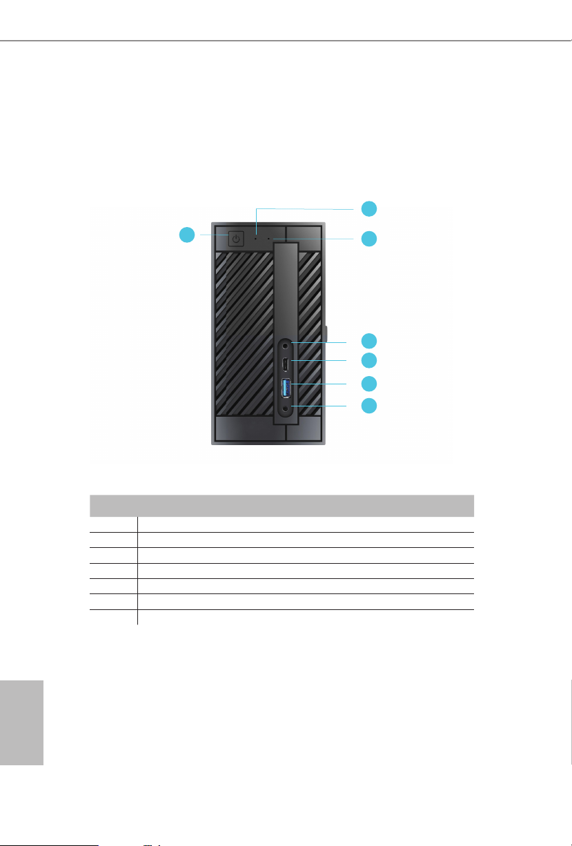
2.1 Front View
2
1
No. Description
1 Power Button
2 Power LED
3 HDD LED
4 MIC-In
5 USB 3.0 Type-A Port
6 USB 3.0 Type-C Port
7 Headphone/Headset
3
4
5
6
7
English
4 5
Page 10
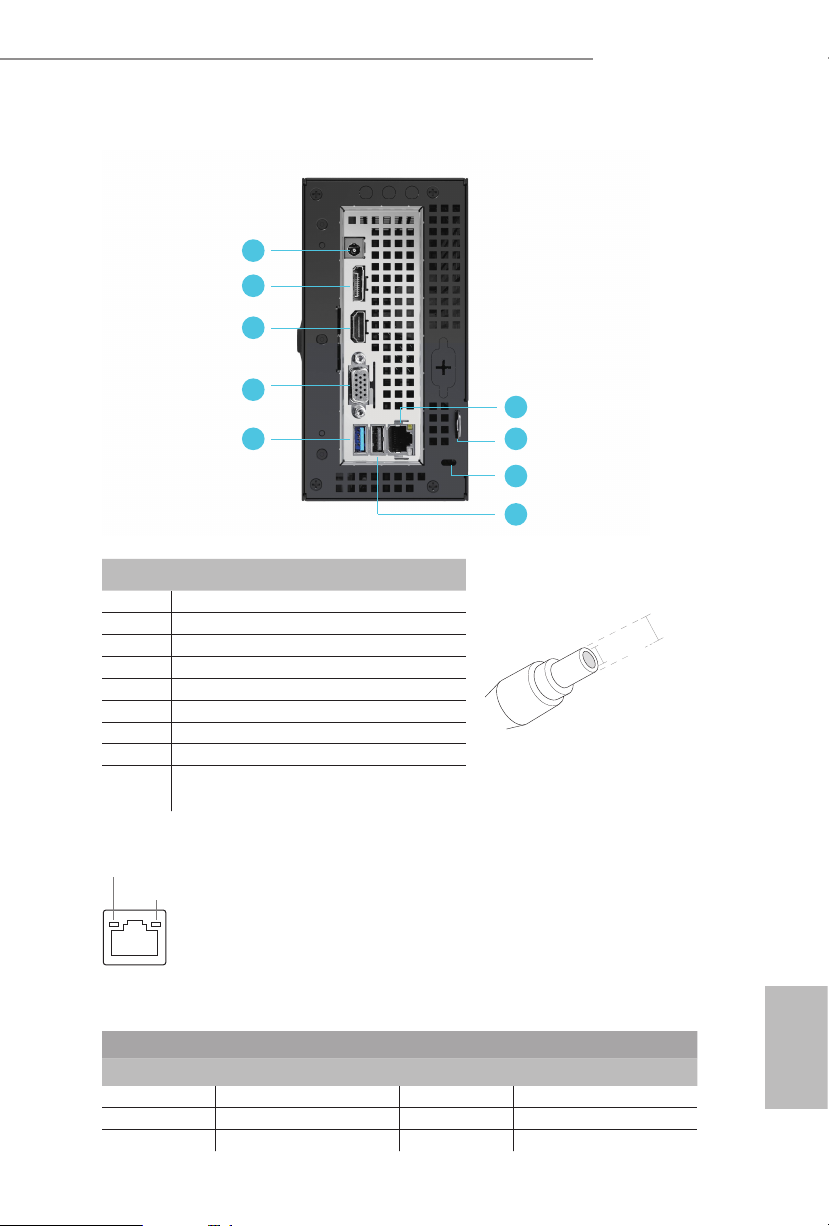
2.2 Rear View
DeskMini series
1
2
3
4
6
5
7
8
9
No. Description
1 DC Jack
2 Display Port
3 HDMI Port
4 D-Sub Port
5 USB 3.0 Port
6 LAN RJ-45 Port**
7 Key Lock
8 Kensington Lock
9 USB 2.0 Port (for DeskMini 110 series)
** ere are two LEDs on the LAN port. Please refer to the table below for the LAN port LED indications.
ACT/LINK LED
SPEED LED
(Supports 19V 120W Power Adapters)
USB 3.0 Port (for DeskMini 170 series)
*Specication for DC plug
*
2.5 mm
5.5 mm
LAN Por t
Activity / Link LED Speed LED
Status Description Status Description
O No Link O 10Mbps connection
Blinking Data Activity Orange 100Mbps connection
On Link Green 1Gbps connection
English
Page 11
Intel
Chipset
Top:
RJ-45
USB 2.0
T: USB3
USB 3.0
B: USB4
H110M-STX
RoHS
1
2
5
6
7
8
Audio
CODEC
USB_5_6
1
CPU_FAN1
3
4
HDLED RESET
PLED PWRBTN
PANEL1
1
Mic In
USB 3.0
USB_2
USB 3.0
USB_1
Headphone
/ Headset
VGA1
9
DDR 4_A1DDR 4_A1
DDR 4_B1
DC Jack
HDMI1
DP1
1
CI1
1
LPC1
CPU_FAN2
SPEAKER1
1
Super
I/O
BIOS
ROM
M.2 W iFi
M.2 P CIe SSD
M2_2_CT1M2_1_CT1
COM1
1
English
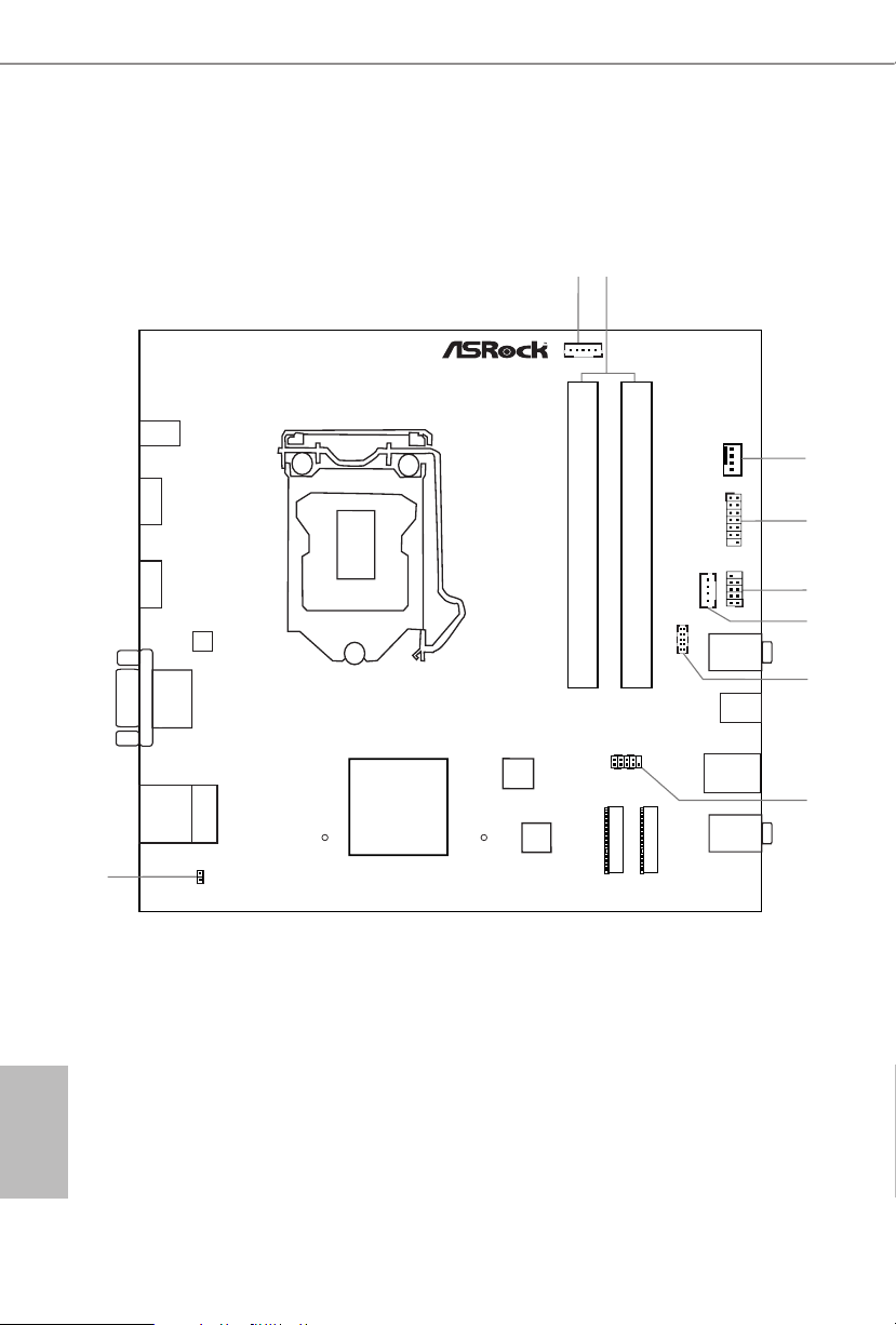
2.3 Motherboard Layout
Top View
6 7
Page 12
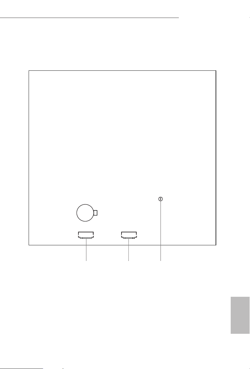
SATA3 SATA3
Bottom View
DeskMini series
CMOS
Battery
10 11
12
English
Page 13

No. Description
1 5-Pin CPU Fan Connector (CPU_FAN2)
2 2 x 260-pin DDR4 SO-DIMM Slots (DDR4_A1, DDR4_B1)
3 4-Pin CPU Fan Connector (CPU_FAN1)
4 LPC Debug Header (LPC1)
5 USB 2.0 Header (USB_5_6)
6 MONO Speaker Header (SPEAKER1)
7 COM Port Header (COM1) (only for DeskMini 110/COM)
8 System Panel Header (PANEL1)
9 Chassis Intrusion Header (CI1)
10 SATA3 Connector (SATA1)
11 SATA3 Connector (SATA2)
12 Clear CMOS Pad
English
8 9
Page 14
Onboard Headers and Connectors
Onboard headers and connectors are NOT jump ers. Do NOT place jumper caps over these
heade rs and connectors. Placing jumper caps over the headers and connectors will cause
permanent damage to the motherboard.
DeskMini series
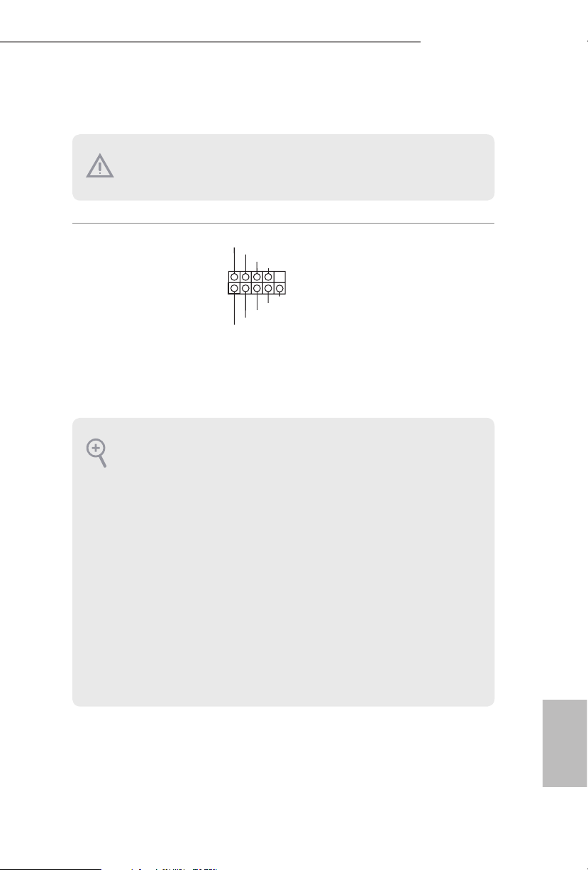
System Panel Header
(9-pi n PANEL1)
(see p.6, No. 8)
PWRBTN (Power Switch):
Connec t to the power switch on the ch assi s front panel. You may congure the way to tur n
o your system using the power switch.
RESET (Reset Switch):
Connec t to the reset switch on the chassi s front panel. Press the reset sw itch to restart the
computer if the computer f reezes and fails to per form a normal restar t.
PLED (Syste m Power LED):
Connec t to the power status indicator on the chas sis front panel. e LED i s on when the
system is operating. e LED keeps blinking when the system is in S1/S3 sleep state. e
LED is o when the system is in S4 slee p state or powered o (S5).
HDLED (Ha rd Drive Activity LED):
Connec t to the hard drive ac tivity LED on the chassis front panel. e LED is on when the
hard drive is reading or wr iting data.
e front panel de sign may dier by chassis. A front panel module mainly consists of powe r
switch, reset switch , power LED, hard dr ive activity LED, speaker and etc. When connecting your ch assi s front panel module to thi s header, make sure the wire a ssignments and the
pin assignments are matched correctly.
1
PLED+
PLED-
HDLED-
HDLED+
PWRBTN#
GND
RESET#
GND
GND
Connect the power
switch, reset switch and
system status indicator on
the chassis to this header
according to the pin
assignments below. Note
the positive and negative
pins before connecting
the cables.
English
Page 15
MONO Speaker Header
DUMMY
GNDGND
P+
P-
P+
P-
USB_PWR
USB_PWR
1
Front_R+
1
1
2
3
4
(4-p i n SPEAKER1)
(see p.6, No. 6)
Front_L-
Front_L+
Front_R-
Please connect the chassis
speaker to this header.
English
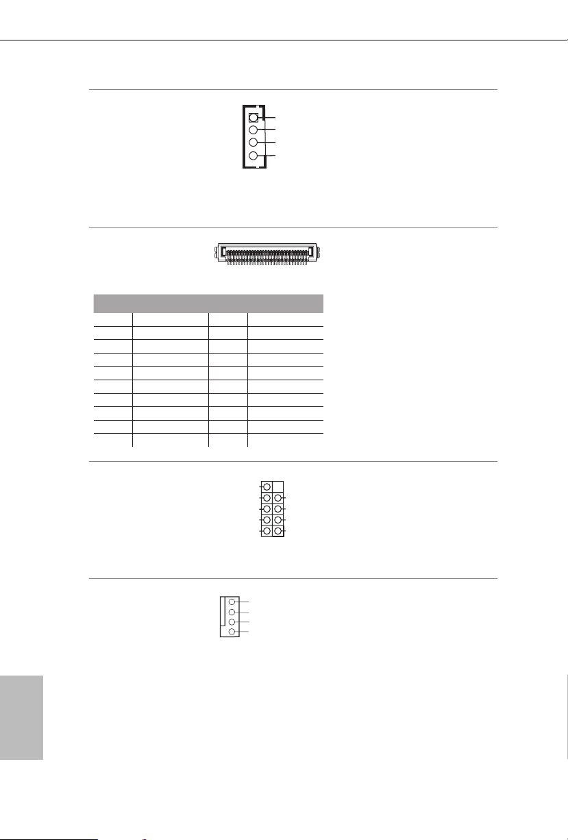
Serial ATA3 Connectors
(see p.7, No. 10 and 11)
1
PIN Signal Name PIN Signal Name
1 GND 11 N /A
2 LVDS _TX+ 12 5V
3 LVDS _TX- 13 5V
4 GND 14 5V
5 GND 15 5V
6 LV DS_R X- 16 5V
7 LVDS _ R X+ 17 N/A
8 GND 18 GND
9 GND 19 GND
10 GND 20 GND
USB 2.0 Header
(9-pin USB_5_6)
(see p.6, No. 5)
CPU Fan Connector
(4-pin CPU_FAN1)
(see p.6, No. 3)
GN D
+ 12V
CPU_FAN_SPEED
FAN_SPEED_CONTROL
ese two SATA3
20
connectors support SATA
data cables for internal
storage devices with up to
6.0 Gb/s data transfer rate.
*e SATA3 connectors
support 2.5-inch hard
drive (+5V) and do not
support 3.5-inch hard
drive (+12V)
ere is one header on
this motherboard. is
USB 2.0 header can
support two ports.
is motherboard
provides a 4-Pin CPU fan
(Quiet Fan) connector.
If you plan to connect a
3-Pin CPU fan, please
connect it to Pin 1-3.
10 11
Page 16
DeskMini series
1
Signa
1
FAN_VOLTAG
FAN_SPEED_CONTROL
S
GN
DC
R
R
D
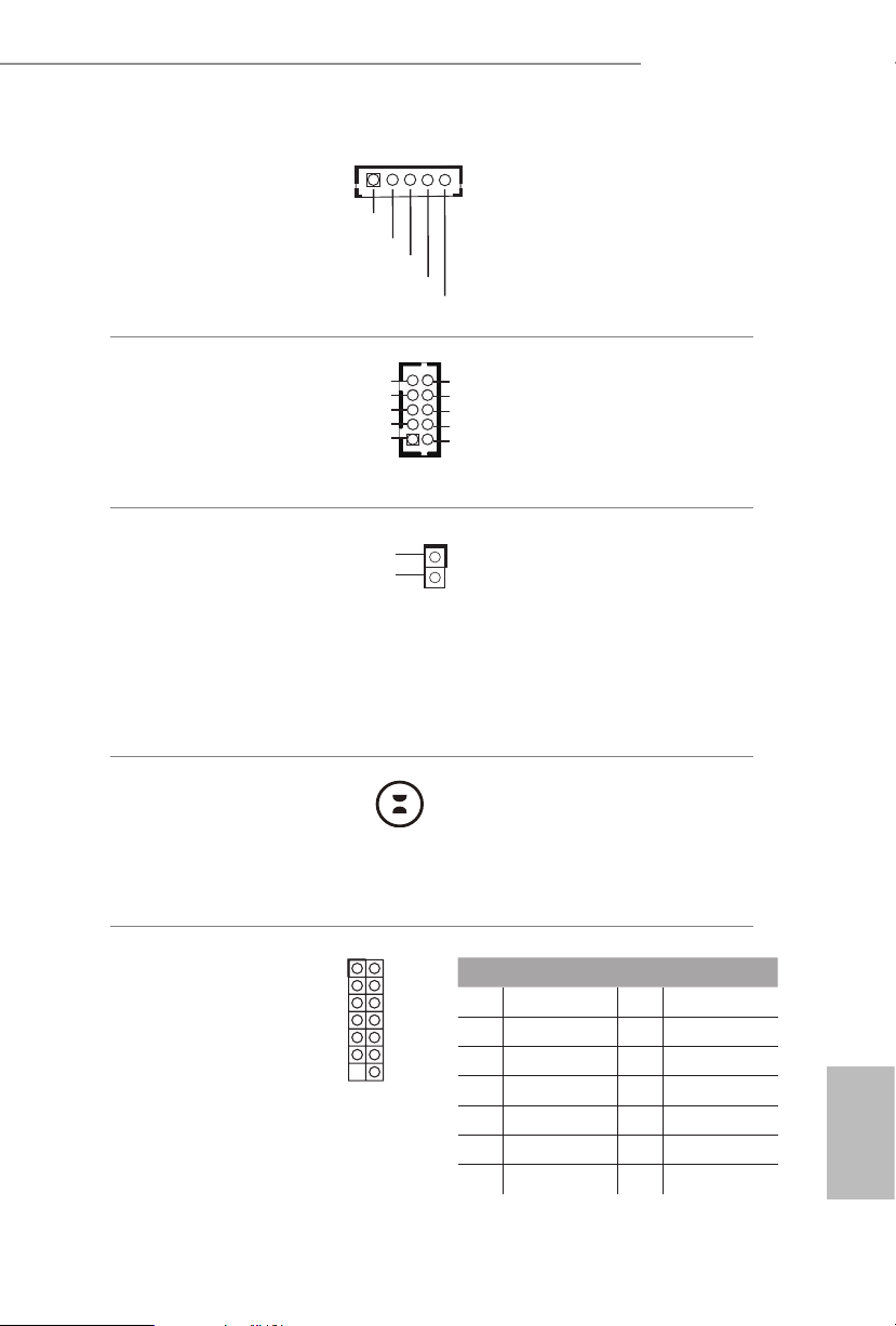
CPU Fan Connector
(5-pin CPU_FAN2)
(see p.6, No. 1)
Serial Port Header
(only for DeskMini 110/
COM)
(9-p in CO M1)
(see p.6, No. 7)
Chassis Intrusion Header
(2-pin CI1)
(see p.6, No. 9)
Clear CMOS Pad
(see p.7, No. 12)
GND
GND
FAN_SPEED
RI
RTS
D
TXD
D
GND
l
is motherboard
provides a 5-Pin CPU fan
connector. is connector
E
1
supports Intel® 1L ermal
Modules.
is COM1 header
NC
CT
supports a serial port
DS
module.
DT
RX
is motherboard
supports CASE OPEN
detection feature that
detects if the chassis cove
has been removed. is
feature requires a chassis
with chassis intrusion
detection design.
Clear CMOS Pad allows you to
clear the data in CMOS. To clear
CMOS, disconnect the
power supply and short the Clear
CMOS Pad.
LPC Debug Header
(13 -pi n LP C1)
(see p.6, No. 4)
PIN Signal Name PIN Signal Name
1 CLK 2 GND
3 RESET# 4 LFRAME#
5 LAD0 6 LA D1
7 LAD2 8 LAD3
9 LAD3 10 LAD3
11 +3V 12 +3V
13 No pin 14 +3V
English
Page 17
Chapter 3 Hardware Installation
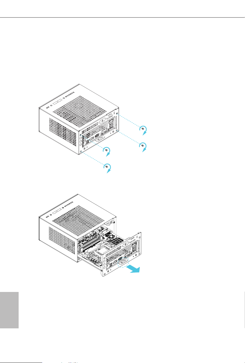
3.1 Begin Installation
1. Unscrew the four screws of the back panel.
2. Pull out the motherboard tray while holding the handle .
English
12 13
Page 18
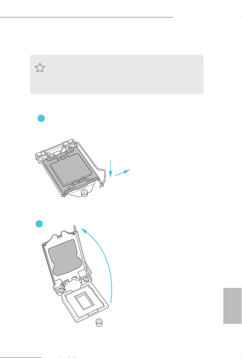
3.2 Installing the CPU
1. Before you insert the 1151-Pin CPU into the socket, please check if the P nP cap is on the
socket, if the CPU surface is unclean, or if there are any bent pins in the sock et. Do not
force to in sert the CPU into the socket if above situation is found . Otherwise, the CPU
will be seriously damaged.
2. Unplug all power c ables before in stalling the CPU.
1
DeskMini series
A
B
2
English
Page 19
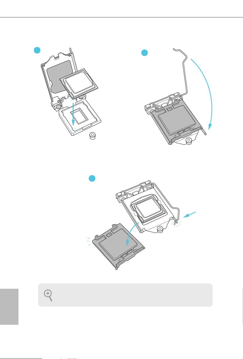
3
4
5
English
Please save and replace the cover if the processor i s removed. e cover must be placed if
you wish to return the motherboard for aer service.
14 15
Page 20
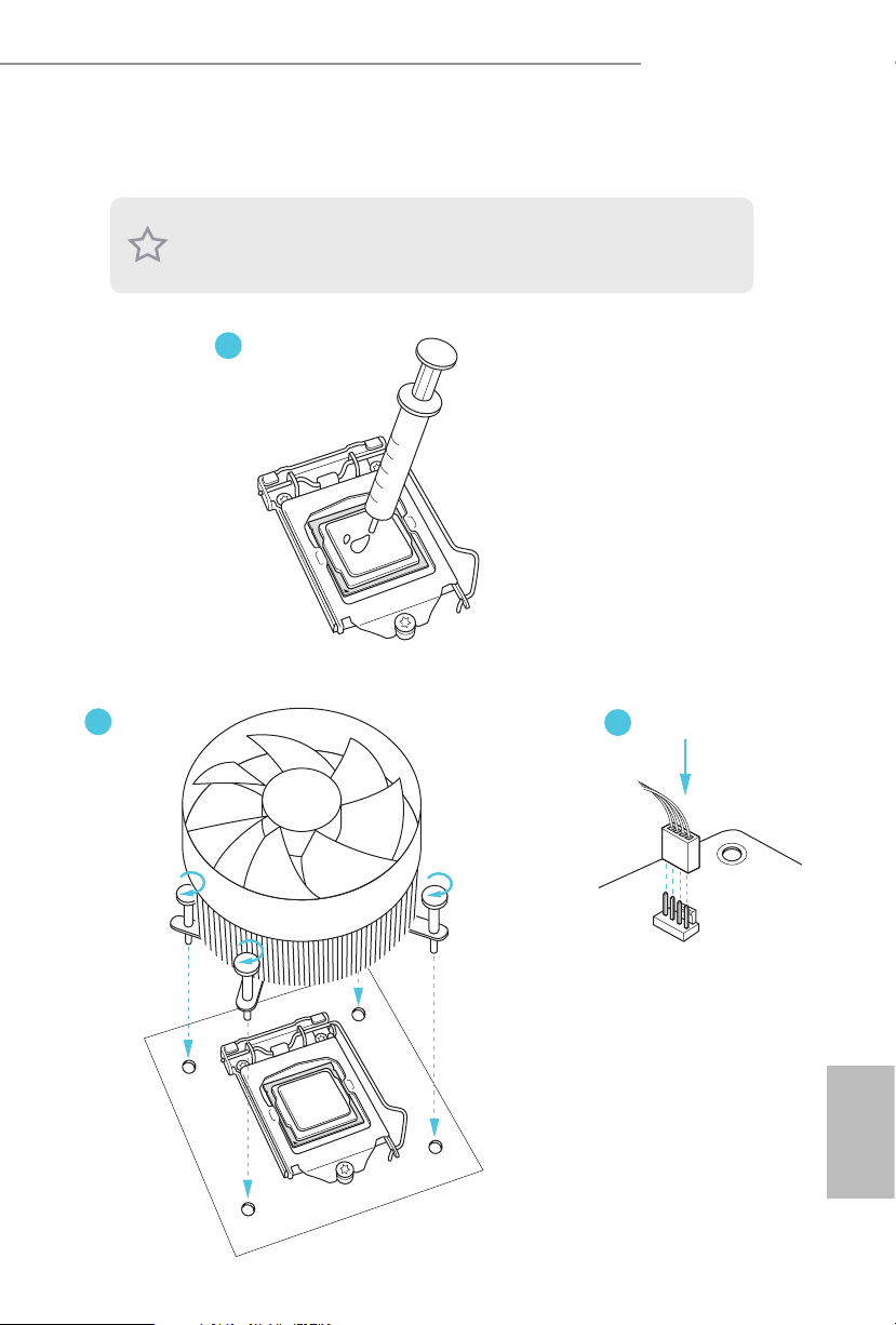
3.3 Installing the CPU Fan and Heatsink
DeskMini 110 series supports both Intel CPU Box Fan (65W) and third-party CPU fan
cooler. Please note that the DeskMini 110 series chassis has 52mm height limitation for the
CPU fan cool er.
1
DeskMini series
2
3
FAN
CPU_
English
Page 21
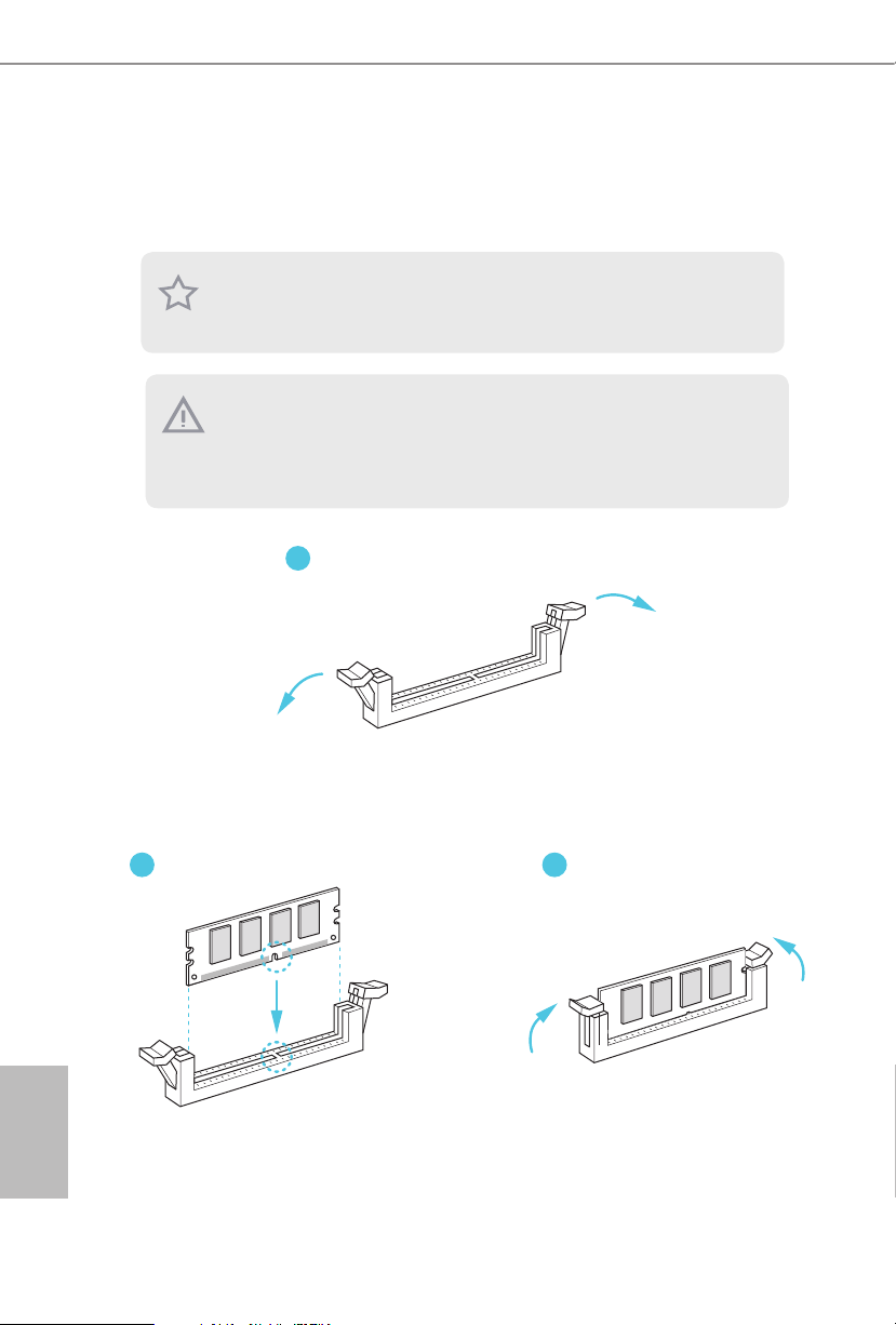
3.4 Installing Memory Modules (SO-DIMM)
is motherboard provides two 260-pin DDR4 (Double Data Rate 4) SO-DIMM
slots.
1. DeskMini 110 series requires DDR4 SO-DIM M.
2. For dual channel conguration , you always need to in stall identical (the same brand,
speed , size and chip-type) DDR4 SO-DIMM pairs.
1. It is not all owed to in stall a DDR, DDR2 or DDR 3 memor y module into a DDR4 slot;
otherwise , this motherboard and SO-DIMM may be damaged.
2. e SO-DIMM only ts in one correc t orientation . It will cause pe rmanent damage to
the motherboard and the SO-DIMM if you force the SO-DIMM into the sl ot at incorrect
orientation.
1
32
English
16 17
Page 22
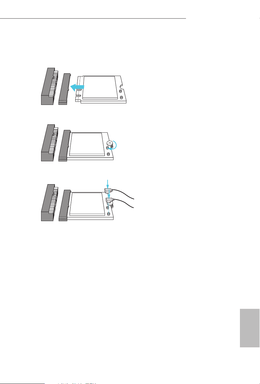
3.5 Installing the WiFi Module
1. Insert the WiFi Module Card into the M.2 Slot for WiFi + BT Module.
2. Tighten the screw to secure the WiFi Module Card to the motherboard.
3. Attach the SMA Wi-Fi Antenna Cables to the WiFi Module.
DeskMini series
English
Page 23

3.6 Installing the M.2 SSD (Type 2280)
1. Locate the M.2 slot on the motherboard
2. Carefully insert the M.2 SSD into the slot.
3. Tighten the screw to secure the M.2 SSD to the motherboard.
.
English
18 19
Page 24

DeskMini series
3.7 Installing the 2.5-inch HDD/SSD
1. Place another HDD/SSD on the tray B shown in Step 1. en turn the motherboard
tray upside down and secure the HDD/SSD with the four screws.
*Removing the motherboard before installing the second HDD/SSD.
B
A
2. Connect the SATA Data and Power Cable to the HDD/SSD.
3. Connect the other end of the SATA Cables to the SATA Connectors on the
motherboard.
English
Page 25

4. Place another HDD/SSD on the tray B shown in Step 1.
en turn the motherboard tray upside down and secure the HDD/SSD with the four
screws.
*Removing the motherboard before installing the second HDD/SSD.
5. Connect the SATA Data and Power Cable to the HDD/SSD.
6. Connect the other end of the SATA Cables to the SATA Connectors on the motherboard.
English
20 21
Page 26

DeskMini series
3.8 Complete
1. Connect the power button cable to the System Panel Header on the motherboard.
PANEL1
2. Align the motherboard tray with the two sliding tracks on the chassis while sliding it
back to the chassis.
Sliding Track
3. en refasten the four screws that you removed earlier.
English
Page 27
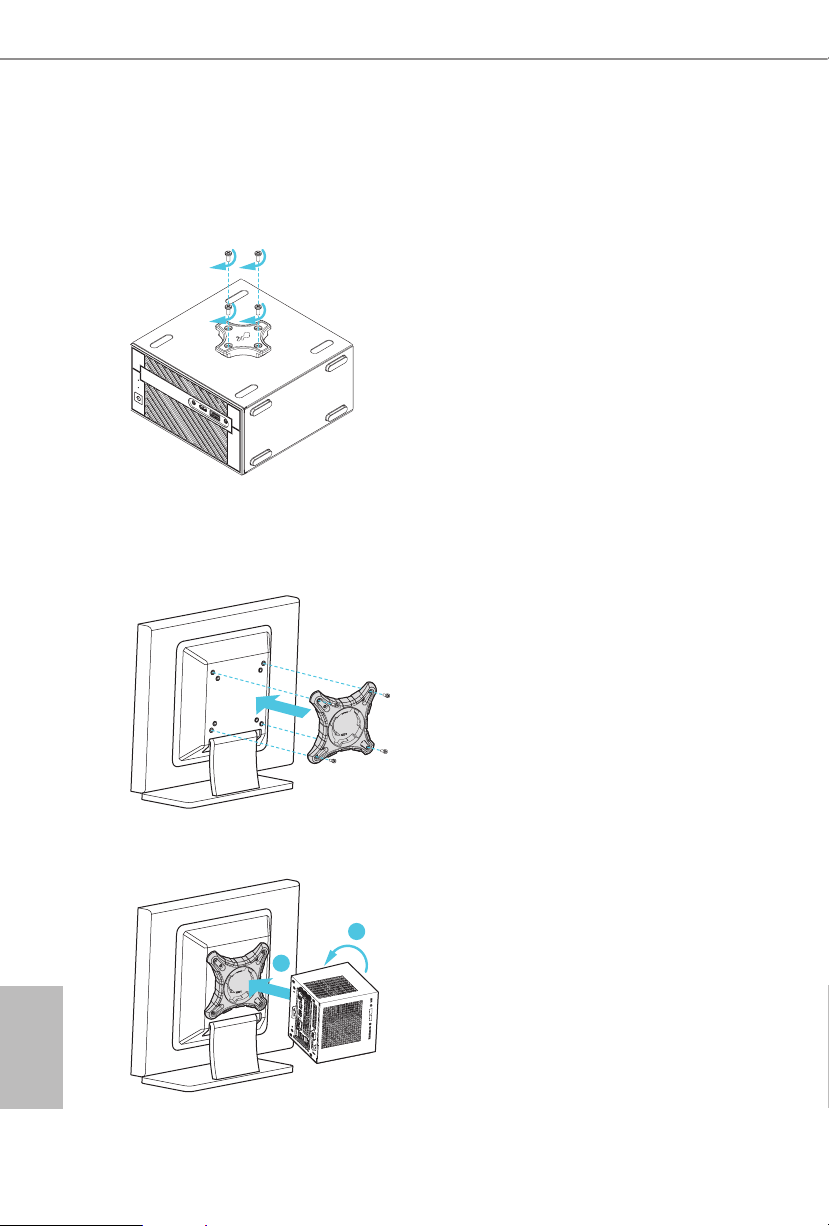
3.9 Installing the VESA Bracket (Optional)
1. Secure the VESA Bracket to the right side panel of the DeskMini 110 series by using the
four screws.
2. Attach the other VESA Bracket to the rear of a compatible display using the four
screws.
*Choose mounting holes depending on the mounting hole pattern of your LCD screen
(75 mm × 75 mm or 100 mm × 100 mm).
3. Mount the DeskMini 110 series by turning it counterclockwise.
B
A
English
22 23
Page 28

4. Complete.
DeskMini series
English
Page 29

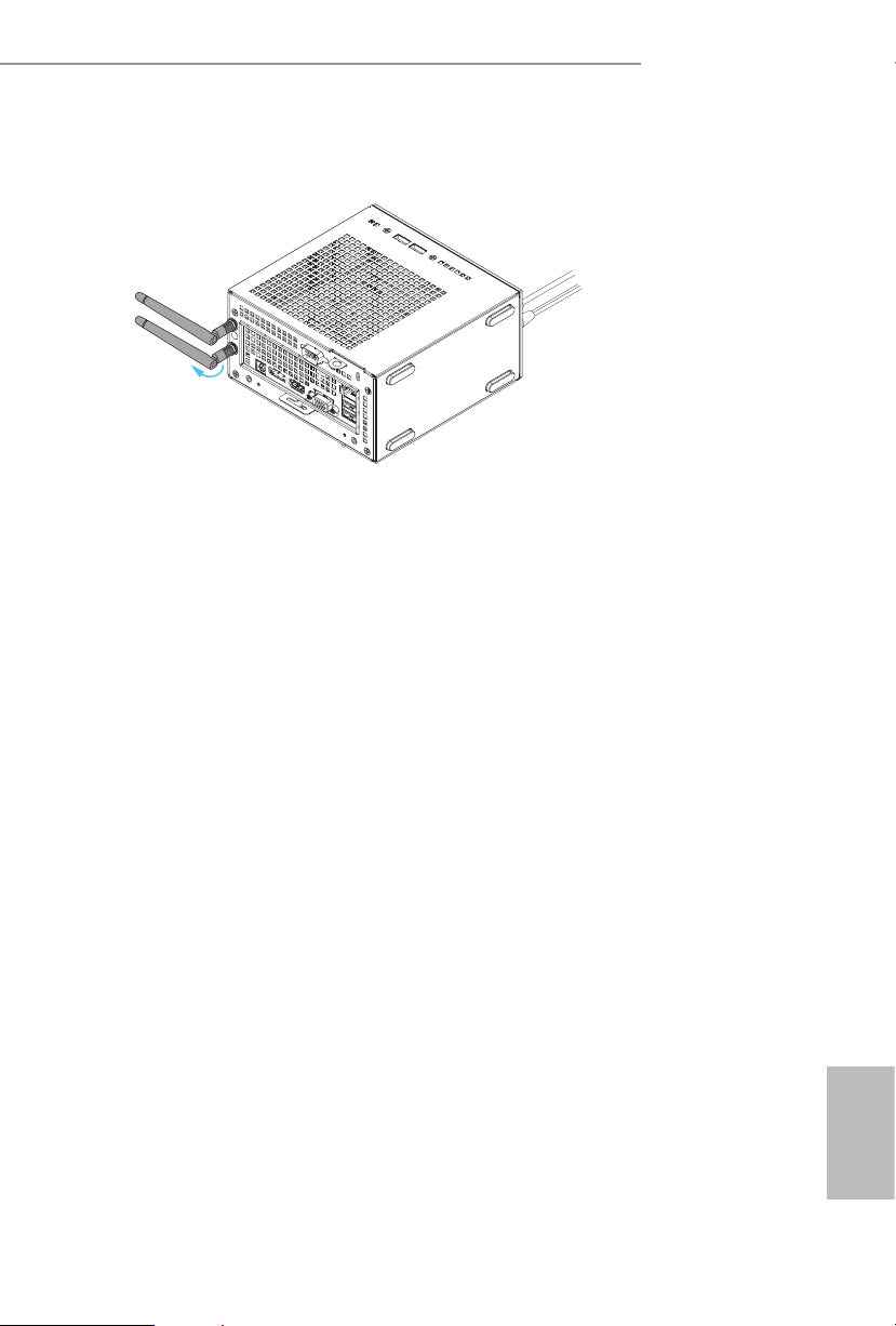
4.0 Installing the WiFi Antennas (Optional)
1. Insert the Wi-Fi Antenna Connectors to the antenna ports on the rear panel of the
DeskMini 110 series
*Please make sure to align the at surface of Wi-Fi Antenna Connectors with the at
side of holes when inserting the connectors.
2. Fasten the screw nuts to secure the antenna connectors.
3. Connect the two WiFi 2.4/5 GHz Antennas to the antenna connectors. Turn the
antenna clockwise until it is securely connected.
English
24 25
Page 30
4. Set the WiFi 2.4/5 GHz Antenna at 90-degree angle.
*You may need to adjust the direction of the antenna for a stronger signal.
DeskMini series
English
Page 31

Chapter 4 Software and Utilities Operation
4.1 Installing Drivers
e Support CD that comes with the motherboard contains necessary drivers and
useful utilities that enhance the motherboard’s features.
Running The Support CD
To begin using the support CD, insert the CD into your CD-ROM drive. e CD
automatically displays the Main Menu if “AUTORUN” is enabled in your computer.
If the Main Menu does not appear automatically, locate and double click on the le
“ASRSETUP.EXE” in the Support CD to display the menu.
Drivers Menu
e drivers compatible to your system will be auto-detected and listed on the
support CD driver page. Please click Install All or follow the order from top to
bottom to install those required drivers. erefore, the drivers you install can work
properly.
Utilities Menu
e Utilities Menu shows the application soware that the motherboard supports.
Click on a specic item then follow the installation wizard to install it.
To improve Windows 7 compatibility, please download and install the following hot x
provided by Microso.
“KB2720599”: http://support.microso.com/kb/2720599/en-us
English
26 PB
Page 32

DeskMini series
4.2 ASRock Live Update & APP Shop
e ASRock Live Update & APP Shop is an online store for purchasing and
downloading soware applications for your ASRock computer. You can quickly and
easily install various apps and support utilities, such as USB Key, XFast LAN, XFast
RAM and more. With ASRock APP Shop, you can optimize your system and keep
your motherboard up to date simply with a few clicks.
Double-click on your desktop to access ASRock Live Update & APP Shop
utility.
*You need to be connected to the Internet to download apps f rom the ASRock Live Update & APP Shop.
4.2.1 UI Overview
Category Panel
Hot News
Information Panel
Category Panel: e category panel contains several category tabs or buttons that
when selected the information panel below displays the relative information.
Information Panel: e information panel in the center displays data about the
currently selected category and allows users to perform job-related tasks.
Hot News: e hot news section displays the various latest news. Click on the image
to visit the website of the selected news and know more.
English
Page 33

4.2.2 Apps
When the "Apps" tab is selected, you will see all the available apps on screen for you
to download.
Installing an App
Step 1
Find the app you want to install.
e most recommended app appears on the le side of the screen. e other various
apps are shown on the right. Please scroll up and down to see more apps listed.
You can check the price of the app and whether you have already intalled it or not.
- e red icon displays the price or "Free" if the app is free of charge.
- e green "Installed" icon means the app is installed on your computer.
Step 2
Click on the app icon to see more details about the selected app.
English
28 29
Page 34

DeskMini series
Step 3
If you want to install the app, click on the red icon to start downloading.
Step 4
When installation completes, you can nd the green "Installed " icon appears on the
upper right corner.
To uninstall it, simply click on the trash can icon .
*e trash icon may not appear for certain apps.
English
Page 35

Upgrading an App
You can only upgrade the apps you have already installed. When there is an
available new version for your app, you will nd the mark of "New Version"
appears below the installed app icon.
Step 1
Click on the app icon to see more details.
Step 2
Click on the yellow icon to start upgrading.
English
30 31
Page 36

4.2.3 BIOS & Drivers
Installing BIOS or Drivers
When the "BIOS & Drivers" tab is selected, you will see a list of recommended or
critical updates for the BIOS or drivers. Please update them all soon.
DeskMini series
Step 1
Please check the item information before update. Click on to see more details.
Step 2
Click to select one or more items you want to update.
Step 3
Click Update to start the update process.
English
Page 37

4.2.4 Setting
In the "Setting" page, you can change the language, select the server location, and
determine if you want to automatically run the ASRock Live Update & APP Shop
on Windows startup.
English
32 PB
Page 38

DeskMini series
4.3 Enabling USB Ports for Windows® 7 Installation
Intel® Braswell and Skylake has removed their support for the Enhanced Host
Controller Interface (EHCI – USB2.0) and only kept the eXtensible Host Controller
Interface (XHCI – USB3.0). Due to that fact that XHCI is not included in the
Windows 7 inbox drivers, users may nd it dicult to install Windows 7 operating
system because the USB ports on their motherboard won’t work. In order for the
USB ports to function properly, please create a Windows® 7 installation disk with
the Intel® USB 3.0 eXtensible Host Controller (xHCI) drivers packed into the ISO
le.
Requirements
A Windows® 7 installation disk or USB drive
•
A Windows® PC
•
Win7 USB Patcher (included in the ASRock Support CD or downloaded from
•
website)
English
Page 39

Instructions
Step 1
Insert the Windows® 7 insta llation disk or USB drive to your system.
Step 2
Extract the tool (Win7 USB Patcher) and launch it.
Step 3
Select "Create a Windows 7 installation disk with a USB device".
Step 4
Locate your Win7 source folder or your ISO le.
English
34 35
Page 40

DeskMini series
Step 5
Select the USB storage, compact disk or destination folder for the new Windows 7
installation le.
Step 6
Click “Start” to begin.
Step 7
Now you are able to install Windows® 7 on Braswell or Skylake with the new burned CD.
Or please use the patched ISO image to make an OS USB drive to install the OS.
English
Page 41

Chapter 5 UEFI SETUP UTILITY
5.1 Introduction
is section explains how to use the UEFI SETUP UTILITY to congure your
system. You may run the UEFI SETUP UTILITY by pressing <F2> or <Del> right
aer you power on the computer, other wise, the Power-On-Self-Test (POST) will
continue with its test routines. If you wish to enter the UEFI SETUP UTILITY aer
POST, restart the system by pressing <Ctl> + <Alt> + <Delete>, or by pressing the
reset button on the system chassis. You may also restart by turning the system o
and then back on.
Becau se the UEFI soware is constantly being upd ated, the following UEFI setup
screens and de scriptions are for refe rence purpose only, and they may not exactly
match what you see on your scre en.
English
36 37
Page 42

DeskMini series
5.2 EZ Mode
e EZ Mode screen appears when you enter the BIOS setup program by default. EZ
mode is a dashboard which contains multiple readings of the system’s current status.
You can check the most crucial information of your system, such as CPU speed,
DRAM frequency, SATA information, fan speed, etc.
Press <F6> or click the "Advanced Mode" button at the upper right corner of the
screen to switch to "Advanced Mode" for more options.
Desk Mini 110 :
English
Page 43

DeskMini 110/COM:
No. Function
Help
1
Load UEFI Defaults
2
Save Changes and Exit
3
Discard Changes
4
Change Language
5
Switch to Advanced Mode
6
English
38 39
Page 44

DeskMini series
5.3 Advanced Mode
e Advanced Mode provides more options to congure the BIOS settings. Refer to
the following sections for the detailed congurations.
To access the EZ Mode, press <F6> or click the "EZ Mode" button at the upper right
corner of the screen.
5.3.1 UEFI Menu Bar
e top of the screen has a menu bar with the following selections:
Main
OC Tweaker
Advanced
Tool
H/W Monitor
Boot
Security
Exit
For setting system time/date information
For overclocking congurations
For advanced system congurations
Useful tools
Displays current hardware status
For conguring boot settings and boot priority
For security settings
Exit the current screen or the UEFI Setup Utility
English
Page 45

5.3.2 Navigation Keys
Use < > key or < > key to choose among the selections on the menu bar, and
use < > key or < > key to move the cursor up or down to select items, then
press <Enter> to get into the sub screen. You can also use the mouse to click your
required item.
Please check the following table for the descriptions of each navigation key.
Navigation Key(s) Description
+ / -
<Tab>
<PGUP>
<PGDN>
<HOME>
<END>
<F1>
<F5>
<F7>
<F9>
<F10>
<F12>
<ESC>
To change option for the selected items
Switch to next function
Go to the previous page
Go to the next page
Go to the top of the screen
Go to the bottom of the screen
To display the General Help Screen
Add / Remove Favorite
Discard changes and exit the SETUP UTILITY
Load optimal default values for all the settings
Save changes and exit the SETUP UTILITY
Print screen
Jump to the Exit Screen or exit the current screen
English
40 41
Page 46

5.4 Main Screen
When you enter the UEFI SETUP UTILITY, the Main screen will appear and
display the system overview.
Desk Mini 110 :
DeskMini series
DeskMini 110/COM:
My Favorite
Display your collection of BIOS items. Press F5 to add/remove your favorite items.
English
Page 47

5.5 OC Tweaker Screen
In the OC Tweaker screen, you can set up overclocking features.
Becau se the UEFI soware is constantly being upd ated, the following UEFI setup
screens and de scriptions are for refe rence purpose only, and they may not exactly
match what you see on your scre en.
DDR4 Non-Z OC
Please note that overclocking may cause damage to your memory DIMMs and mother-
board. It should be done at your own risk and expense. Please use a better cooling solu-
tion while overclocking. e option colored in red might make your system unstable. It
depends on the quality of the memory DIMMs and system environment.
CPU Conguration
Intel SpeedStep Technology
Intel SpeedStep technology allows processors to switch between multiple frequen-
English
cies and voltage points for better power saving and heat dissipation.
Intel Speed Shift Technology
Enable this option to expose the Collaborative Processor Performance Control
(CPPC) v2 interface to allow hardware controlled P-states.
42 43
Page 48

DeskMini series
Intel Turbo Boost Technology
Intel Turbo Boost Technolog y enables the processor to run above its base operating
frequency when the operating system requests the highest performance state.
Long Duration Power Limit
Congure Package Power Limit 1 in watts. When the limit is exceeded, the CPU
ratio will be lowered aer a period of time. A lower limit can protect the CPU and
save power, while a higher limit may improve performance.
Long Duration Maintained
Congure the period of time until the CPU ratio is lowered when the Long
Duration Power Limit is exceeded.
Short Duration Power Limit
Congure Package Power Limit 2 in watts. When the limit is exceeded, the CPU
ratio will be lowered immediately. A lower limit can protect the CPU and save
power, while a higher limit may improve performance.
DRAM Conguration
DRAM Tweaker
Fine tune the DRAM settings by leaving marks in checkboxes. Click OK to conrm and
apply your new settings.
DRAM Timing Conguration
DRAM Reference Clock
Select Auto for optimized settings.
DRAM Frequency
If [Auto] is selected, the motherboard will detect the memory module(s) inserted
and assign the appropriate frequency automatically.
Primary Timing
CAS# Latency (tCL)
e time between sending a column address to the memory and the beginning of the data
in response.
English
Page 49

RAS# to CAS# Delay and Row Precharge (tRCDtRP)
RAS# to CAS# Delay : e number of clock cycles required between the opening of a row
of memory and accessing columns within it.
Row Precharge: e number of clock cycles required between the issuing of the precharge
command and opening the next row.
RAS# Active Time (tRAS)
e number of clock cycles required between a bank active command and issuing the
precharge command.
Command Rate (CR)
e delay between when a memor y chip is selected and when the rst active command can
be issued.
Secondary Timing
Write Recovery Time (tWR)
e amount of delay that must elapse aer the completion of a valid write operation,
before an active bank can be precharged.
Refresh Cycle Time (tRFC)
e number of clocks from a Refresh command until the rst Activate command to
the same rank.
RAS to RAS Delay (tRRD_L)
e number of clocks between two rows activated in dierent banks of the same
rank.
RAS to RAS Delay (tRRD_S)
e number of clocks between two rows activated in dierent banks of the same
rank.
Write to Read Delay (tWTR_L)
e number of clocks between the last valid write operation and the next read command to
the same interna l bank.
English
Write to Read Delay (tWTR_S)
e number of clocks between the last valid write operation and the next read command to
the same interna l bank.
44 45
Page 50

Read to Precharge (tRTP)
e number of clocks that are inserted between a read command to a row pre-
charge command to the same rank.
Four Activate Window (tFAW)
e time window in which four activates are allowed the same rank.
CAS Write Latency (tCWL)
Congure CAS Write Latency.
Third Timing
tREFI
Congure refresh cycles at an average periodic interval.
tCKE
Congure the period of time the DDR4 initiates a minimum of one refresh
command internally once it enters Self-Refresh mode.
tRDRD_sg
Congure between module read to read delay.
DeskMini series
tRDRD_dg
Congure between module read to read delay.
tRDRD_dr
Congure between module read to read delay.
tRDRD_dd
Congure between module read to read delay.
tRDWR_sg
Congure between module read to write delay.
tRDWR_dg
Congure between module read to write delay.
tRDWR_dr
Congure between module read to write delay.
English
Page 51

tRDWR_dd
Congure between module read to write delay.
tWRRD_sg
Congure between module write to read delay.
tWRRD_dg
Congure between module write to read delay.
tWRRD_dr
Congure between module write to read delay.
tWRRD_dd
Congure between module write to read delay.
tWRWR_sg
Congure between module write to write delay.
tWRWR_dg
Congure between module write to write delay.
tWRWR_dr
Congure between module write to write delay.
tWRWR_dd
Congure between module write to write delay.
RTL Init Value
Congure round trip latency init value for round trip latency training.
IO-L Init Value
Congure IO latency init value for IO latency traning.
RTL (CH A)
Congure round trip latency for channel A.
English
RTL (CH B)
Congure round trip latency for channel B.
46 47
Page 52

DeskMini series
IO-L (CH A)
Congure IO latency for channel A.
IO-L (CH B)
Congure IO latency for channel B.
IO-L Oset (CH A)
Congure IO latency oset for channel A.
IO-L Oset (CH B)
Congure IO latency oset for channel B.
RFR Delay (CH A)
Congure RFR Delay for Channel A.
RFR Delay (CH B)
Congure RFR Delay for Channel B.
Fourth Timing
twRPRE
Congure twR PRE.
Write_Early_ODT
Congure Write_Early_ODT.
tAONPD
Congure tAONPD.
tXP
Congure tXP.
tXPDLL
Congure tXPDLL.
tPRPDEN
Congure tPRPDEN.
tRDPDEN
Congure tRDPDEN.
English
Page 53

twRPDEN
Congure twR PDEN.
OREF_RI
Congure OREF_RI.
tREFIx9
Congure tR EFIx9.
txSDLL
Congure txSDLL.
txs_oset
Congure txs_oset.
tZQOPER
Congure tZQOPER.
tMOD
Congure tMOD.
ZQCS_period
Congure ZQCS_period.
tZQCS
Congure tZQCS.
Advanced Setting
ODT WR (CH A)
Congure the memory on die termination resistors' WR for channel A.
ODT WR (CH B)
Congure the memory on die termination resistors' WR for channel B.
ODT PARK (CH A)
English
Congure the memory on die termination resistors' PARK for channel A.
ODT PARK (CH B)
Congure the memory on die termination resistors' PARK for channel B.
48 49
Page 54

ODT NOM (CH A)
Use this to change ODT (CH A) Auto/Manual settings. e default is [Auto].
ODT NOM (CH B)
Use this to change ODT (CH B) Auto/Manual settings. e default is [Auto].
MRC Fast Boot
Enable Memory Fast Boot to skip DRAM memory training for booting faster.
Dll Bandwidth 0
Congure the Dll Bandwidth 0.
Dll Bandwidth 1
Congure the Dll Bandwidth 1.
Dll Bandwidth 2
Congure the Dll Bandwidth 2.
Dll Bandwidth 3
Congure the Dll Bandwidth 3.
DeskMini series
Margin Limit
Adjust Margin Limit to get better memory margin.
Voltage Conguration
DRAM Voltage
Use this to congure DRAM Voltage. e default value is [Auto].
Save User Default
Type a prole name and press enter to save your settings as user default.
Load User Default
Load previously saved user defaults.
English
Page 55

5.6 Advanced Screen
In this section, you may set the congurations for the following items: CPU
Conguration, Chipset Conguration, Storage Conguration, Super IO Congura-
tion, ACPI Conguration and USB Conguration.
Setting wrong values in this sec tion may cause the system to malfunction.
UEFI Conguration
UEFI Setup Style
Select the default mode when entering the UEFI setup utility.
Active Page on Entry
Select the default page when entering the UEFI setup utility.
English
50 51
Page 56

5.6.1 CPU Conguration
Active Processor Cores
Select the number of cores to enable in each processor package.
DeskMini series
CPU C States Support
Enable CPU C States Support for power saving. It is recommended to keep C3, C6
and C7 all enabled for better power saving.
Enhanced Halt State (C1E)
Enable Enhanced Halt State (C1E) for lower power consumption.
CPU C3 State Support
Enable C3 sleep state for lower power consumption.
CPU C6 State Support
Enable C6 deep sleep state for lower power consumption.
CPU C7 State Support
Enable C7 deep sleep state for lower power consumption.
Package C State Support
Enable CPU, PCIe, Memor y, Graphics C State Support for power saving.
English
Page 57

CPU Thermal Throttling
Enable CPU internal thermal control mechanisms to keep the CPU from overheat-
ing.
No-Execute Memory Protection
Processors with No-Execution Memory Protection Technology may prevent certain
classes of malicious buer overow attacks.
Intel Virtualization Technology
Intel Virtualization Technology allows a platform to run multiple operating systems
and applications in independent partitions, so that one computer system can
function as multiple virtual systems.
Hardware Prefetcher
Automatically prefetch data and code for the processor. Enable for better
performance.
Adjacent Cache Line Prefetch
Automatically prefetch the subsequent cache line while retrieving the currently
requested cache line. Enable for better performance.
Software Guard Extensions (SGX)
Enable or disable the support for Intel® Soware Guard Extensions (Intel® SGX).
English
52 53
Page 58

5.6.2 Chipset Conguration
Top of Lower Usable DRAM
Set the maximum value of TOLUD. Set this item to Dynamic to allow TOLUD to
adjust automatically based on the largest MMIO length of the installed graphic
cont roller.
DeskMini series
VT-d
Intel® Virtualization Technology for Directed I/O helps your virtual machine
monitor better utilize hardware by improving application compatibility and
reliability, and providing additional levels of manageability, security, isolation, and
I/O performance.
PCIE ASPM Support
is option enables/disables the ASPM support for all CPU downstream devices.
PCH PCIE ASPM Support
is option enables/disables the ASPM support for all PCH PCIE devices.
DMI ASPM Support
is option enables/disables the control of ASPM on CPU side of the DMI Link.
English
Page 59

PCH DMI ASPM Support
is option enables/disables the ASPM support for all PCH DMI devices.
IOAPI C 24-119 Entr ies
Enable or disable IOAPIC 24-119 Entries to expand your PIROI-PIROX.
Share Memory
Congure the size of memory that is allocated to the integrated graphics processor when
the system boots up.
Onboard LAN
Enable or disable the onboard network interface controller.
Onboard HD Audio
Enable/disable onboard HD audio. Set to Auto to enable onboard HD audio and
automatically disable it when a sound card is installed.
Onboard HDMI HD Audio
Enable audio for the onboard digital outputs.
WAN Radio
Enable/disable the WiFi module's connectivity.
Deep Sleep
Congure deep sleep mode for power saving when the computer is shut down.
Restore on AC/Power Loss
Select the power state aer a power failure. If [Power O] is selected, the power will
remain o when the power recovers. If [Power On] is selected, the system will start
to boot up when the power recovers.
Good Night LED
By enabling Good Night LED, the Power/HDD LEDs will be switched o when the
system is on. It will also automatically switch o the Power and Keyboard LEDs
when the system enters into Standby/Hibernation mode.
English
54 55
Page 60

5.6.3 Storage Conguration
SATA Controller(s)
Enable/disable the SATA controllers.
DeskMini series
SATA Aggressive Link Power Management
SATA Aggressive Link Power Management allows SATA devices to enter a low
power state during periods of inactivity to save power. It is only supported by AHCI
mode.
Hard Disk S.M.A.R.T.
S.M.A.R.T stands for Self-Monitoring, Analysis, and Reporting Technology. It is a
monitoring system for computer hard disk drives to detect and report on various
indicators of reliability.
English
Page 61

5.6.4 Super IO Conguration
Serial Port
Enable or disable the Serial port.
(fo
r DeskMini 110/COM only)
Serial Port Address (for DeskMini 110/COM only)
Select the address of the Serial port.
English
56 57
Page 62

DeskMini series
5.6.5 ACPI Conguration
Suspend to RAM
Select disable for ACPI suspend type S1. It is recommended to select auto for ACPI
S3 power saving.
ACPI HEPT Table
Enable the High Precision Event Timer for better performance.
Wake From Onboard LAN
Allow the system to be waked up by the onboard LAN.
Ring-In Power On
Allow the system to be waked up by onboard COM port modem Ring-In signals.
RTC Alarm Power On
Allow the system to be waked up by the real time clock alarm. Set it to By OS to let
it be handled by your operating system.
USB Keyboard/Remote Power On
Allow the system to be waked up by an USB keyboard or remote controller.
USB Mouse Power On
Allow the system to be waked up by an USB mouse.
English
Page 63

5.6.6 USB Conguration
Legacy USB Support
Enable or disable Legacy OS Support for USB 2.0 devices. If you encounter USB
compatibility issues it is recommended to disable legacy USB support. Select UEFI
Setup Only to support USB devices under the UEFI setup and Windows/Linux
operating systems only.
PS/2 Simulator
Enable this item for the complete USB keyboard legacy support for non-USB aware
operating system.
XHCI Hand-o
is is a workaround for OSes without XHCI hand-o support. e XHCI
ownership change should be claimed by XHCI driver.
English
58 59
Page 64

DeskMini series
5.7 Tools
OMG (Online Management Guard)
Administrators are able to establish an internet curfew or restrict internet access
at specied times via OMG. You may schedule the starting and ending hours of
internet access granted to other users. In order to prevent users from bypassing
OMG, guest accounts without permission to modify the system time are required.
UEFI Tech Service
Contact ASRock Tech Service if you are having trouble with your PC. Please setup
network conguration before using UEFI Tech Service.
Easy Driver Installer
For users that don’t have an optical disk drive to install the drivers from our support
CD, Easy Driver Installer is a handy tool in the UEFI that installs the LAN driver
to your system via an USB storage device, then downloads and installs the other
required drivers automatically.
English
Page 65

Boot Manager
Boot Manager is specically designed for the dual OS platform/multi-OS platform
users to easily customize and manage the boot menu.
*Please connect more than one boot devices to use this tool.
Boot Manager
Enable/disable the Boot Manager.
Boot Manager Timeout
Enable/disable the Boot Manager Timeout.
Timeout Seconds
Congure the number of seconds to wait for the Boot Manager.
Instant Flash
Save UEFI les in your USB storage device and run Instant Flash to update your
UEFI.
Internet Flash - DHCP (Auto IP), Auto
English
ASRock Internet Flash downloads and updates the latest UEFI rmware version
from our servers for you. Please setup network conguration before using Internet
Flash.
*For BIOS backup and recovery purpose, it is recommended to plug in your USB
pen drive before using this function.
60 61
Page 66

Network Conguration
Use this to congure internet connection settings for Internet Flash.
Internet Setting
Enable or disable sound eects in the setup utility.
DeskMini series
UEFI Download Server
Select a server to download the UEFI rmware.
English
Page 67

5.8 Hardware Health Event Monitoring Screen
is section allows you to monitor the status of the hardware on your system,
including the parameters of the CPU temperature, motherboard temperature, fan
speed and voltage.
Fan-Tastic Tuning
Select a fan mode for CPU Fan, or choose Customize to set 5 CPU temperatures and
assign a respective fan speed for each temperature.
CPU Fan 1 Setting
Select a fan mode for CPU Fan 1, or choose Customize to set 5 CPU temperatures
and assign a respective fan speed for each temperature.
CPU Fan 2 Setting
Select a fan mode for CPU Fan 2, or choose Customize to set 5 CPU temperatures
and assign a respective fan speed for each temperature.
Case Open Feature
Enable or disable Case Open Feature to detect whether the chassis cover has been
English
removed.
62 63
Page 68

DeskMini series
5.9 Security Screen
In this section you may set or change the supervisor/user password for the system.
You may also clear the user password.
Supervisor Password
Set or change the password for the administrator account. Only the administrator
has authority to change the settings in the UEFI Setup Utility. Leave it blank and
press enter to remove the password.
User Password
Set or change the password for the user account. Users are unable to change the
settings in the UEFI Setup Utility. Leave it blank and press enter to remove the
password.
Secure Boot
Use this item to enable or disable support for Windows 8.1 Secure Boot.
Intel(R) Platform Trust Technology
Enable/disable Intel PTT in ME. Disable this option to use discrete TPM Module.
English
Page 69

5.10 Boot Screen
is section displays the available devices on your system for you to congure the
boot settings and the boot priority.
Fast Boot
Fast Boot minimizes your computer's boot time. In fast mode you may not boot
from an USB storage device. Ultra Fast mode is only supported by Windows 8.1
and the VBIOS must support UEFI GOP if you are using an external graphics card.
Please notice that Ultra Fast mode will boot so fast that the only way to enter this
UEFI Setup Utility is to Clear CMOS or run the Restart to UEFI utility in Windows.
Boot From Onboard LAN
Allow the system to be waked up by the onboard LAN.
Setup Prompt Timeout
Congure the number of seconds to wait for the setup hot key.
Bootup Num-Lock
Select whether Num Lock should be turned on or o when the system boots up.
English
Boot Beep
Select whether the Boot Beep should be turned on or o when the system boots up. Please
note that a buzzer is needed.
64 65
Page 70

DeskMini series
Full Screen Logo
Enable to display the boot logo or disable to show normal POST messages.
AddOn ROM Display
Enable AddOn ROM Display to see the AddOn ROM messages or congure the
AddOn ROM if you've enabled Full Screen Logo. Disable for faster boot speed.
Boot Failure Guard
If the computer fails to boot for a number of times the system automatically restores
the default settings.
Boot Failure Guard Count
Congure the number of attempts to boot until the system automatically restores
the default settings.
English
Page 71

CSM (Compatibility Support Module)
CSM
Enable to launch the Compatibility Support Module. Please do not disable unless
you’re running a WHCK test. If you are using Windows 8.1 64-bit and all of your
devices support UEFI, you may also disable CSM for faster boot speed.
Launch PXE OpROM Policy
Select UEFI only to run those that support UEFI option ROM only. Select Legacy
only to run those that support legacy option ROM only. Select Do not launch to not
execute both legacy and UEFI option ROM.
Launch Storage OpROM Policy
Select UEFI only to run those that support UEFI option ROM only. Select Legacy
only to run those that support legacy option ROM only. Select Do not launch to not
execute both legacy and UEFI option ROM.
Launch Video OpROM Policy
English
Select UEFI only to run those that support UEFI option ROM only. Select Legacy
only to run those that support legacy option ROM only. Select Do not launch to not
execute both legacy and UEFI option ROM.
66 67
Page 72

DeskMini series
5.11 Exit Screen
Save Changes and Exit
When you select this option the following message, “Save conguration changes
and exit setup?” will pop out. Select [OK] to save changes and exit the UEFI SETUP
UTILITY.
Discard Changes and Exit
When you select this option the following message, “Discard changes and exit
setup?” will pop out. Select [OK] to exit the UEFI SETUP UTILITY without saving
any changes.
Discard Changes
When you select this option the following message, “Discard changes?” will pop
out. Select [OK] to discard all changes.
Load UEFI Defaults
Load UEFI default values for a ll options. e F9 key can be used for this operation.
Launch EFI Shell from lesystem device
Copy shellx64.e to the root directory to launch EFI Shell.
English
Page 73

Contact Information
If you need to contact ASRock or want to know more about ASRock, you’re welcome
to visit ASRock’s website at http://ww w.asrock.com; or you may contact your dealer
for further information. For technical questions, please submit a support request
form at http://www.asrock.com/support/tsd.asp
ASRock Incorporation
2F., No.37, Sec. 2, Jhongyang S. Rd., Beitou District,
Taipei City 112, Taiwan (R.O.C.)
ASRock EUROPE B.V.
Bijsterhuizen 11-11
6546 AR Nijmegen
e Netherlands
Phone: +31-24-345-44-33
Fax: +31-24-345-44-38
ASRock America, Inc.
13848 Magnolia Ave, Chino, CA91710
U.S.A.
Phone: +1-909-590-8308
Fax: +1-909-590-1026
English
68 PB
 Loading...