

Page 1

Version 1.0
Published November 2021
is device complies with Part 15 of the FCC Rules. Operation is subject to the following
two conditions:
(1) this device may not cause harmful interference, and
(2) this device must accept any interference received, including interference that
may cause undesired operation.
CALIFORNIA, USA ONLY
e Lithium battery adopted on this motherboard contains Perchlorate, a toxic substance
controlled in Perchlorate Best Management Practices (BMP) regulations passed by the
California Legislature. When you discard the Lithium battery in California, USA, please
follow the related regulations in advance.
“Perchlorate Material-special handling may apply, see www.dtsc.ca.gov/hazardouswaste/
perchlorate”
Page 2

AUSTRALIA ONLY
Our goods come with guarantees that cannot be excluded under the Australian Consumer
Law. You are entitled to a replacement or refund for a major failure and compensation for
any other reasonably foreseeable loss or damage caused by our goods. You are also entitled
to have the goods repaired or replaced if the goods fail to be of acceptable quality and the
failure does not amount to a major failure.
e terms HDMI® and HDMI High-Denition Multimedia Interface, and the HDMI
logo are trademarks or registered trademarks of HDMI Licensing LLC in the United
States and other countries.
INTEL END USER SOFTWARE LICENSE AGREEMENT
IMPORTANT - READ BEFORE COPYING, INSTALLING OR USING.
LICENSE. Licensee has a license under Intel’s copyrights to reproduce Intel’s Soware
only in its unmodied and binary form, (with the accompanying documentation, the
“Soware”) for Licensee’s personal use only, and not commercial use, in connection with
Intel-based products for which the Soware has been provided, subject to the following
conditions:
(a) Licensee may not disclose, distribute or transfer any part of the Soware, and You agree
to prevent unauthorized copying of the Soware.
(b) Licensee may not reverse engineer, decompile, or disassemble the Soware.
(c) Licensee may not sublicense the Soware.
(d) e Soware may contain the soware and other intellectual property of third party
suppliers, some of which may be identied in, and licensed in accordance with, an enclosed
license.txt le or other text or le.
(e) Intel has no obligation to provide any support, technical assistance or updates for the
Soware.
OWNERSHIP OF SOFTWARE AND COPYRIGHTS. Title to all copies of the Soware
remains with Intel or its licensors or suppliers. e Soware is copyrighted and protected
by the laws of the United States and other countries, and international treaty provisions.
Licensee may not remove any copyright notices from the Soware. Except as otherwise
expressly provided above, Intel grants no express or implied right under Intel patents,
copyrights, trademarks, or other intellectual property rights. Transfer of the license terminates Licensee’s right to use the Soware.
DISCLAIMER OF WARRANTY. e Soware is provided “AS IS” without warranty of
any kind, EITHER EXPRESS OR IMPLIED, INCLUDING WITHOUT LIMITATION,
WARRANTIES OF MERCHANTABILITY OR FITNESS FOR ANY PARTICULAR PURPOSE.
LIMITATION OF LIABILITY. NEITHER INTEL NOR ITS LICENSORS OR SUPPLIERS
WILL BE LIABLE FOR ANY LOSS OF PROFITS, LOSS OF USE, INTERRUPTION OF
BUSINESS, OR INDIRECT, SPECIAL, INCIDENTAL, OR CONSEQUENTIAL DAMAG
Page 3

ES OF ANY KIND WHETHER UNDER THIS AGREEMENT OR OTHERWISE, EVEN
IF INTEL HAS BEEN ADVISED OF THE POSSIBILITY OF SUCH DAMAGES.
LICENSE TO USE COMMENTS AND SUGGESTIONS. is Agreement does NOT
obligate Licensee to provide Intel with comments or suggestions regarding the Soware.
However, if Licensee provides Intel with comments or suggestions for the modication,
correction, improvement or enhancement of (a) the Soware or (b) Intel products or
processes that work with the Soware, Licensee grants to Intel a non-exclusive, worldwide,
perpetual, irrevocable, transferable, royalty-free license, with the right to sublicense, under
Licensee’s intellectual property rights, to incorporate or otherwise utilize those comments
and suggestions.
TERMINATION OF THIS LICENSE. Intel or the sublicensor may terminate this license
at any time if Licensee is in breach of any of its terms or conditions. Upon termination,
Licensee will immediately destroy or return to Intel all copies of the Soware.
THIRD PARTY BENEFICIARY. Intel is an intended beneciary of the End User License
Agreement and has the right to enforce all of its terms.
U.S. GOVERNMENT RESTRICTED RIGHTS. e Soware is a commercial item (as
dened in 48 C.F.R. 2.101) consisting of commercial computer soware and commercial
computer soware documentation (as those terms are used in 48 C.F.R. 12.212), consistent
with 48 C.F.R. 12.212 and 48 C.F.R 227.7202-1 through 227.7202-4. You will not provide
the Soware to the U.S. Government. Contractor or Manufacturer is Intel Corporation,
2200 Mission College Blvd., Santa Clara, CA 95054.
EXPORT LAWS. Licensee agrees that neither Licensee nor Licensee’s subsidiaries will
export/re-export the Soware, directly or indirectly, to any country for which the U.S.
Department of Commerce or any other agency or department of the U.S. Government
or the foreign government from where it is shipping requires an export license, or other
governmental approval, without rst obtaining any such required license or approval. In
the event the Soware is exported from the U.S.A. or re-exported from a foreign destination by Licensee, Licensee will ensure that the distribution and export/re-export or import
of the Soware complies with all laws, regulations, orders, or other restrictions of the U.S.
Export Administration Regulations and the appropriate foreign government.
APPLICABLE LAWS. is Agreement and any dispute arising out of or relating to it will
be governed by the laws of the U.S.A. and Delaware, without regard to conict of laws
principles. e Parties to this Agreement exclude the application of the United Nations
Convention on Contracts for the International Sale of Goods (1980). e state and federal
courts sitting in Delaware, U.S.A. will have exclusive jurisdiction over any dispute arising
out of or relating to this Agreement. e Parties consent to personal jurisdiction and venue
in those courts. A Party that obtains a judgment against the other Party in the courts identied in this section may enforce that judgment in any court that has jurisdiction over the
Parties.
Licensee’s specic rights may vary from country to country.
Page 4
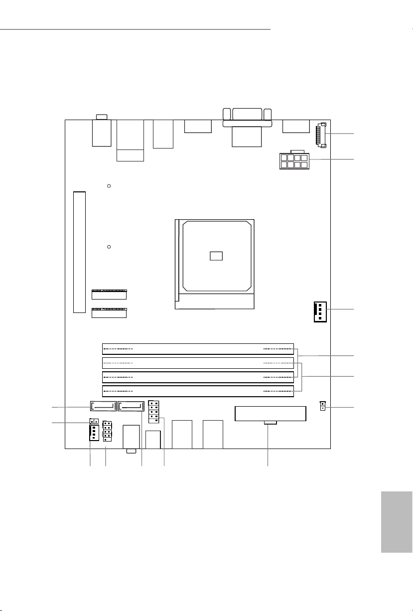
Motherboard Layout
USB 3.2 Gen1
USB3_TC_1
Headphone
/ Headset
VGA1
HDMI1
DP1
CPU_FAN1
SOCKETAM4
RoHS
7
2
DDR4_A2 (64 bit, 288-pin module)
DDR4_A1 (64 bit, 288-pin module)
DDR4_B2 (64 bit, 288-pin module)
DDR4_B1 (64 bit, 288-pin module)
ATXPWR1
SATA3_2
SATA3_1
CHA_
FAN1
PANEL1
1
HDLED RESET
PLED PWRBTN
CI1
1
ATX12V2
M.2 WiFi
M.2 PCIe SSD
PCIE2
USB 3.2 G en1
T: USB3_1
B: USB3 _2
USB 2. 0
T: USB_1
B: USB _2
USB 2. 0
T: USB_3
B: USB _4
3
12
4
5
6
9
RJ-45
Line Out
USB 3.2 Ge n1
USB 3 34_
USB_5_6
1
1
COM1
1
81011
CLRMOS1
1
13
X300-ITX / X300-ITX/COM
English
Page 5

No. Description
1 COM Port Header (COM1) (for X300-ITX/COM only)
2 8 pin 12V Power Connector (ATX12V2)
3 CPU Fan Connector (CPU_FAN1)
4 2 x 288-pin DDR4 DIMM Slots (DDR4_A1, DDR4_B1)
5 2 x 288-pin DDR4 DIMM Slots (DDR4_A2, DDR4_B2)
6 Chassis Intrusion Header (CI1)
7 ATX Power Connector (ATXPWR1)
8 USB 2.0 Header (USB_5_6)
9 SATA3 Connector (SATA3_1)
10 System Panel Header (PANEL1)
11 Chassis Fan Connector (CHA_FAN1)
12 Clear CMOS Jumper (CLRMOS1)
13 SATA3 Connector (SATA3_2)
English
2 3
Page 6
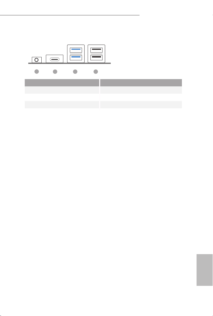
Front Panel
X300-ITX / X300-ITX/COM
1
No. Description No. Description
1 Headphone/Headset Jack (AUDIO1) 3 USB 3.2 Gen1 Type-A Ports
2 USB 3.2 Gen1 Type-C Port (USB3_12)
(USB3_TC_1) 4 USB 2.0 Ports (USB_12)
2 3 4
English
Page 7
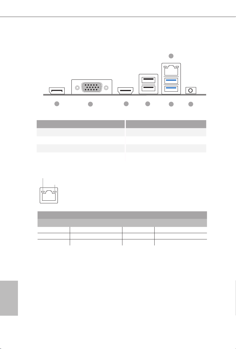
Rear Panel
7
1 3
2 5 6
4
No. Description No. Description
1 DisplayPort 1.2 5 USB 3.2 Gen1 Type-A Ports
2 D-Sub Port (USB3_34)
3 HDMI Port 6 Line out Jack
4 USB 2.0 Ports (USB_34) 7 LAN RJ-45 Port*
* ere are two LEDs on each LAN port. Please refer to the table below for the LAN port LED indications.
ACT/LINK LED
SPEED LED
LAN Por t
Activity / Link LED Speed LED
Status Description Status Description
O No Link O 10Mbps connection
Blinking Data Activity Orange 100Mbps connection
On Link Green 1Gbps connection
English
4 5
Page 8

X300-ITX / X300-ITX/COM
Chapter 1 Introduction
ank you for purchasing X300-ITX / X300-ITX/COM motherboard. In this
documentation, Chapter 1 and 2 contains the introduction of the motherboard and
step-by-step installation guides.
Becau se the motherboard specications and the BIOS soware might be updated, the
content of this documentation will be subject to change without notice.
1.1 Package Contents
X300-ITX / X300-ITX/COM Motherboard (Deep mini-ITX Form Factor)
•
1 x I/O Panel Shield
•
2 x SATA Cables (Optional)
•
1 x Screw for M.2 Socket (M2*2) (Optional)
•
1 x Screw for WiFi Module (M2*2) (Optional)
•
English
Page 9

English
1.2 Specications
Platform
CPU
Chipset
Memory
•
•
•
•
•
•
•
•
•
•
•
•
•
•
•
* For Ryzen Series APUs (Cezanne, Renoir and Picasso), ECC is
only supported with PRO CPUs.
Deep mini-ITX Form Factor
Solid Capacitor design
Supports AMD AM4 Socket RyzenTM 2000, 3000, 4000
G-Series, 5000 and 5000 G-Series Desktop Processors
Supports CPU up to 65W
6 Power Phase design
AMD X300
Dual Channel DDR4 Memory Technology
4 x DDR4 DIMM Slots
AMD Ryzen series APUs (Cezanne) support DDR4
3200/2933/2667/2400/2133 ECC & non-ECC, un-buered
memory*
AMD Ryzen series CPUs (Vermeer) support DDR4
3200/2933/2667/2400/2133 ECC & non-ECC, un-buered
memory*
AMD Ryzen series CPUs (Matisse) support DDR4
3200/2933/2667/2400/2133 ECC & non-ECC, un-buered
memory*
AMD Ryzen series APUs (Renoir) support DDR4
3200/2933/2667/2400/2133 ECC & non-ECC, un-buered
memory*
AMD Ryzen series CPUs (Pinnacle Ridge) support DDR4
2933/2667/2400/2133 ECC & non-ECC, un-buered
memory*
AMD Ryzen series APUs (Picasso) support DDR4
2933/2667/2400/2133 ECC & non-ECC, un-buered
memory*
AMD Ryzen series CPUs (Raven Ridge) support DDR4
2933/2667/2400/2133 ECC & non-ECC, un-buered
memory*
6 7
Page 10

X300-ITX / X300-ITX/COM
* Please refer to page 18 for DDR4 DIMM maximum
frequency support.
Max. capacity of system memory: 128GB
•
15μ Gold Contact in DIMM Slots
•
Expansion
Slot
Graphics
AMD Ryzen series CPUs (Vermeer, Matisse, Pinnacle Ridge)
1 x PCIe Gen3x16 Slot (x16 mode)*
•
AMD Ryzen series APUs (Cezanne, Renoir)
1 x PCIe Gen3x16 Slot (x16 mode)*
•
AMD Ryzen series APUs (Picasso, Raven Ridge)
1 x PCIe Gen3x16 Slot (x8 mode)*
•
AMD Athlon series CPUs
1 x PCIe Gen3x16 Slot (x4 mode)*
•
* Supports NVMe SSD as boot disks
1 x M.2 Socket (Key E), supports type 2230 WiFi/BT module
•
Integrated AMD RadeonTM Vega Series Graphics in Ryzen
•
Series APU*
* Actual support may vary by CPU
DirectX 12, Pixel Shader 5.0
•
Shared memory default 2GB. Max Shared memory supports
•
up to 16GB.
* e Max shared memory 16GB requires 32GB system memory
installed.
ree graphics output options: D-Sub, DisplayPort 1.2 and
•
HDMI
Supports Triple Monitor
•
Supports HDMI with max. resolution up to 4K x 2K
•
(4096x2160) @ 60Hz
Supports D-Sub with max. resolution up to 1920x1200 @
•
60Hz
Supports DisplayPort 1.2 with max. resolution up to 4K x 2K
•
(4096x2304) @ 60Hz
Supports Auto Lip Sync, Deep Color (12bpc), xvYCC and HBR
•
(High Bit Rate Audio) with HDMI Port (Compliant HDMI
monitor is required)
Supports HDCP with HDMI and DisplayPort 1.2 Ports
•
Supports 4K Ultra HD (UHD) playback with HDMI and
•
DisplayPort 1.2 Ports
English
Page 11

Audio
LAN
Front
Panel I/O
Rear Panel
I/O
Realtek ALC897 Audio Codec
•
Supports Surge Protection
•
1 x Headphone/Headset Jack
•
1 x Line out Jack
•
PCIE x1 Gigabit LAN 10/100/1000 Mb/s
•
Realtek RTL8111H
•
Supports Wake-On-LAN
•
Supports Lightning/ESD Protection
•
Supports Energy Ecient Ethernet 802.3az
•
Supports PXE
•
1 x Headphone/Headset Jack
•
2 x USB 3.2 Gen1 Type-A Ports (Supports ESD Protection (Full
•
Spike Protection))
1 x USB 3.2 Gen1 Type-C Port (Supports ESD Protection (Full
•
Spike Protection))
2 x USB 2.0 Ports (Supports ESD Protection (Full Spike
•
Protection))
1 x D-Sub Port
•
1 x HDMI Port
•
1 x DisplayPort 1.2
•
2 x USB 3.2 Gen1 Type-A Ports (Supports ESD Protection (Full
•
Spike Protection))
2 x USB 2.0 Ports (Supports ESD Protection (Full Spike
•
Protection))
1 x RJ-45 LAN Port with LED (ACT/LINK LED and SPEED
•
LED)
1 x Line out Jack
•
2 x SATA3 6.0 Gb/s with Power Connectors, support RAID
Storage
English
•
(RAID 0 and RAID 1), NCQ, AHCI and Hot Plug
1 x Ultra M.2 Socket (M2_1), supports type 2280 M.2 PCI
•
Express module up to Gen3 x4 (32 Gb/s) or Gen3 x2 (16 Gb/s)
(with Athlon 2xxGE series)*
* Supports NVMe SSD as boot disks
8 9
Page 12
Connector
BIOS
Feature
X300-ITX / X300-ITX/COM
1 x COM Port Header (Optional for X300-ITX/COM model)
•
1 x Chassis Intrusion Header
•
1 x CPU Fan Connector
•
* e CPU Fan Connector supports the CPU fan of maximum 1A
(12W) fan power.
1 x Chassis Fan Connector (4-pin)
•
* e Chassis Fan Connector supports the chassis fan of maximum 1A (12W) fan power.
1 x 24 pin ATX Power Connector
•
1 x 8 pin 12V Power Connector
•
1 x Front Panel Header
•
1 x USB 2.0 Header (Supports 2 USB 2.0 ports) (Supports ESD
•
Protection)
AMI UEFI Legal BIOS with GUI support
•
Supports "Plug and Play"
•
ACPI 5.1 compliance wake up events
•
Supports jumperfree
•
SMBIOS 2.3 support
•
DRAM Voltage adjustment
•
CPU, Chassis Temperature Sensing
Hardware
Monitor
OS
Certications
Please realize that the re is a certain risk involved with overclocking, including adjusting
the setting in the BIOS, applying Untied Overclocking Technology, or using third-party
overclocking tools. O verclocking may aect your system’s stability, or even cause damage to
the components and devices of your system. It should be done at your ow n risk and expense.
We are not responsible for possible damage caused by overclocking.
•
CPU, Chassis Fan Tachometer
•
CPU, Chassis Quiet Fan (Auto adjust chassis fan speed by
•
CPU temperature)
CPU, Chassis Fan Multi-Speed Control
•
CASE OPEN detection
•
Voltage monitoring: +12V, +5V, +3.3V, CPU Vcore
•
Microso® Windows® 10 64-bit
•
FCC, CE
•
ErP/EuP ready (ErP/EuP ready power supply is required)
•
English
Page 13

Chapter 2 Installation
is is a Deep mini-ITX form factor motherboard. Before you install the
motherboard, study the conguration of your chassis to ensure that the
motherboard ts into it.
Pre-installation Precautions
Take note of the following precautions before you install motherboard components
or change any motherboard settings.
Make sure to unplug the power cord before installing or removing the motherboard.
•
Failure to do so may cause physical injuries to you and damages to motherboard
components.
In order to avoid damage from static electricity to the motherboard’s components,
•
NEVER place your motherboard directly on a carpet. Also remember to use a grounded
wrist strap or touch a safety grounded object before you handle the components.
Hold components by the edges and do not touch the ICs.
•
Whenever you uninstall any components, place them on a grounded anti-static pad or
•
in the bag that comes with the components.
When placing screws to secure the motherboard to the chassis, please do not over-
•
tighten the screws! Doing so may damage the motherboard.
English
10 11
Page 14

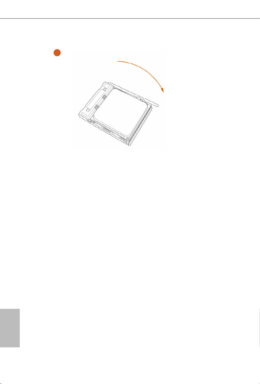
2.1 Installing the CPU
Unplug all power cables be fore installing the CPU.
1
X300-ITX / X300-ITX/COM
2
English
Page 15
3
English
12 13
Page 16
X300-ITX / X300-ITX/COM
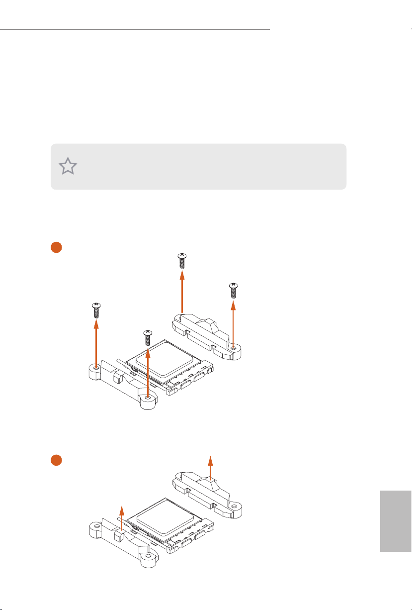
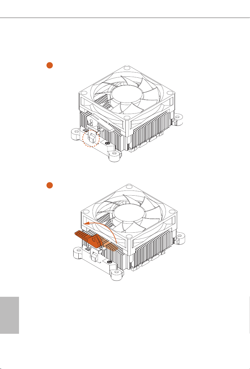
2.2 Installing the CPU Fan and Heatsink
Aer you install the CPU into this motherboard, it is necessary to install a larger
heatsink and cooling fan to dissipate heat. You also need to spray thermal grease
between the CPU and the heatsink to improve heat dissipation. Make sure that the
CPU and the heatsink are securely fastened and in good contact with each other.
Please turn o the power or remove the power cord before changing a CPU or heatsink.
Installing the CPU Box Cooler -1
1
2
English
Page 17
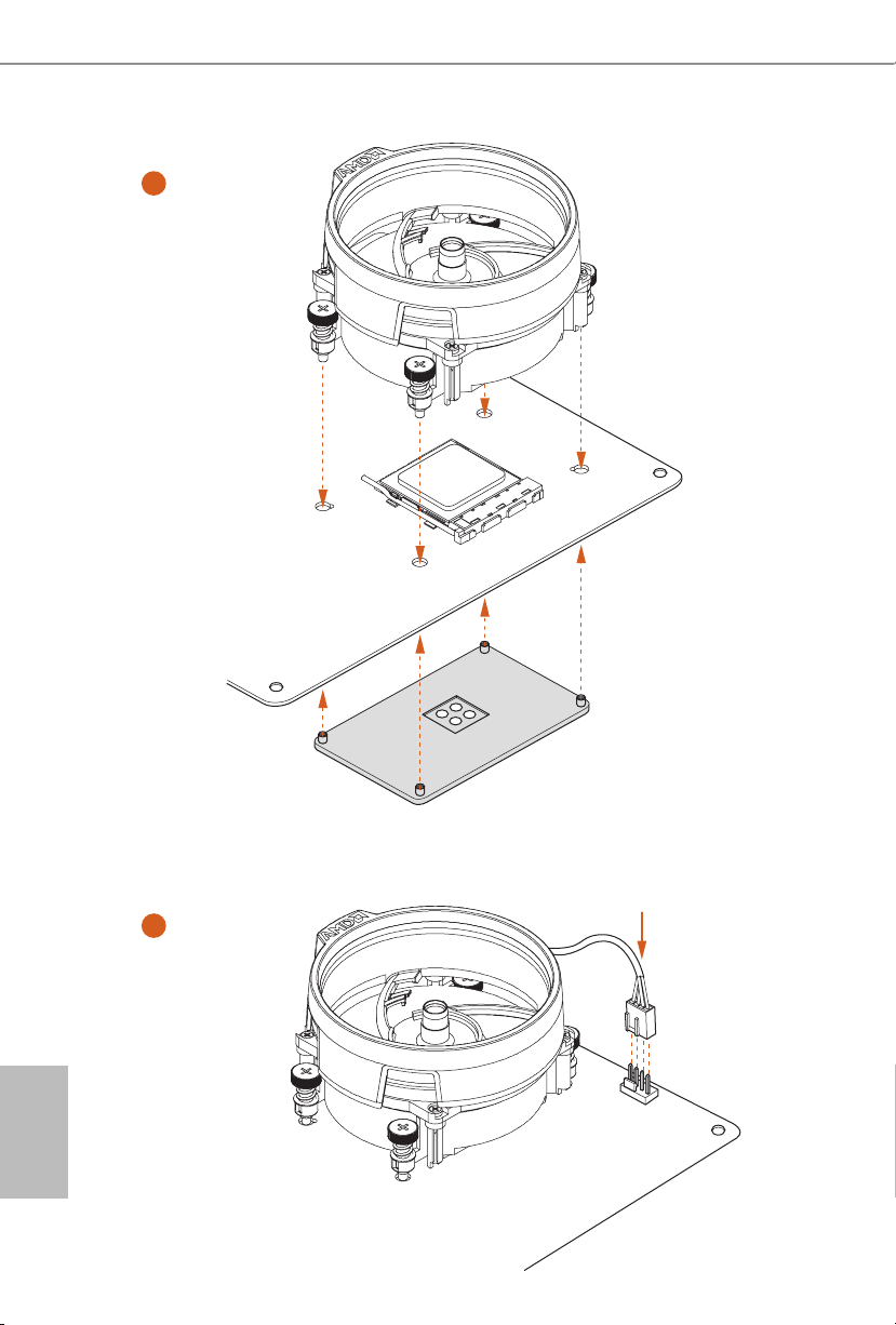
3
4
4-pin FAN cable
English
1
N
FA
_
U
P
C
14 15
Page 18
X300-ITX / X300-ITX/COM
1
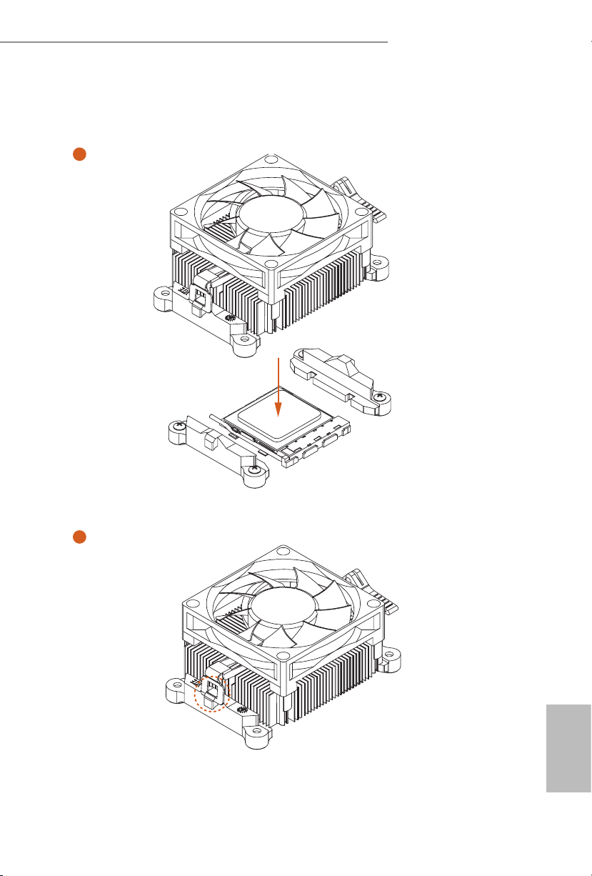
Installing the CPU Box Cooler -2
2
English
Page 19
3
4
English
16 17
Page 20
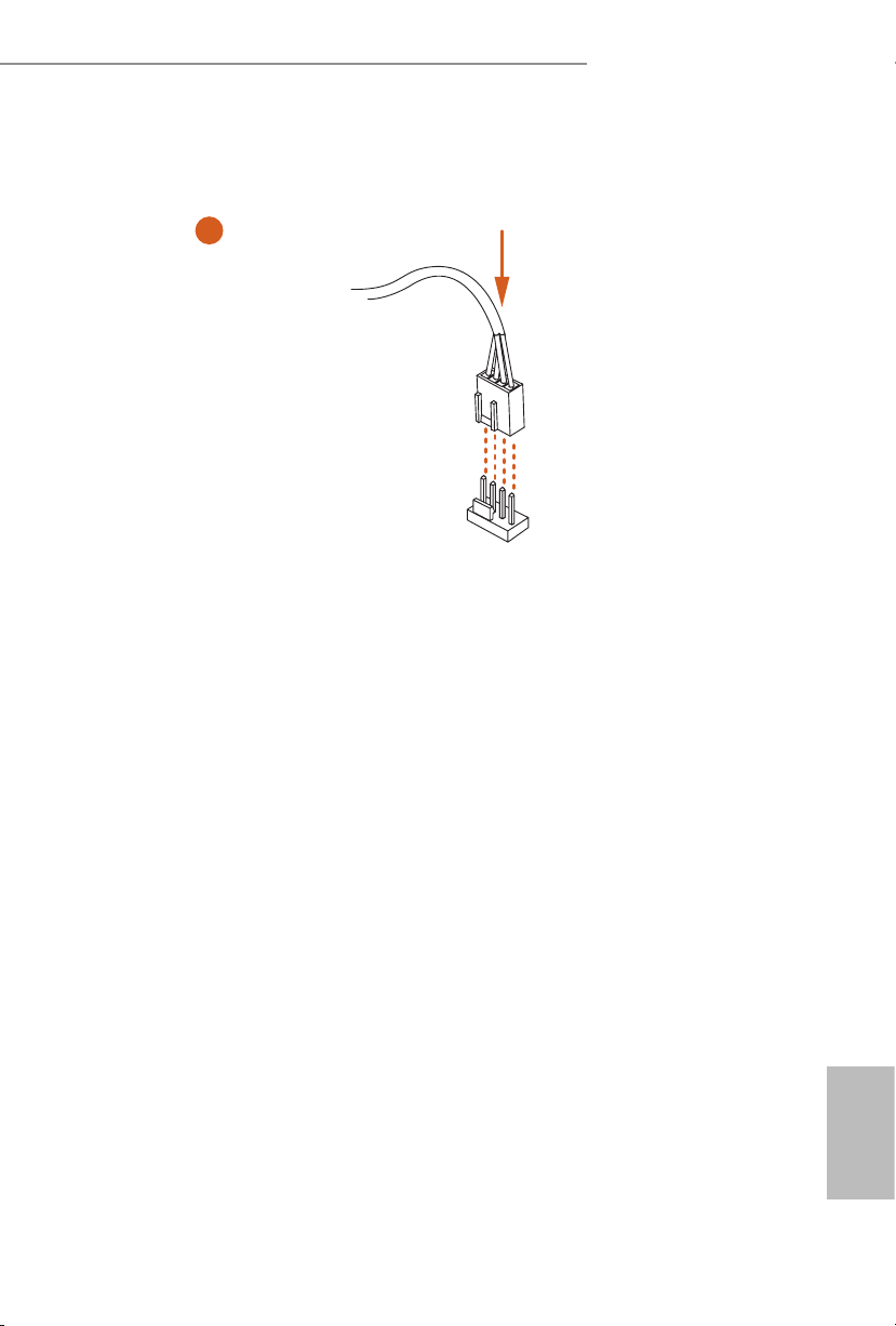
X300-ITX / X300-ITX/COM
AN1
5
4-pin FAN cable
CPU_F
English
Page 21

2.3 Installing Memory Modules (DIMM)
is motherboard provides four 288-pin DDR4 (Double Data Rate 4) DIMM slots,
and supports Dual Channel Memory Technology.
1. For dual channel conguration , you always need to in stall identical (the same
brand, speed , size and chip-type) DDR4 DIMM pairs.
2. It is unable to activate Du al Channel Memory Technology with only one or three
memory module installed.
3. It is not allowed to install a DDR, DDR2 or DDR3 memory module into a DDR4
slot; otherwise, this motherboard and DIMM may be damaged.
4. We suggest that you install the memory modules on DDR4_ A2 and DDR4_B2 rst
for better DRAM compatibility on 2 DIMM s conguration.
AMD non-XMP Memory Frequency Support
Ryzen Series APUs (Cezanne):
UDIMM Memory Slot
A1 A2 B1 B2
Frequency
(Mhz)
- SR - - 3200
- DR - - 3200
- SR - SR 3200
- DR - DR 3200
SR SR SR SR 2933
SR/DR DR SR/DR DR 2667
SR/DR SR/DR SR/DR SR/DR 2667
Ryzen Series CPUs (Matisse):
UDIMM Memory Slot
A1 A2 B1 B2
- SR - - 3200
- DR - - 3200
English
- SR - SR 3200
- DR - DR 3200
SR SR SR SR 2933
SR/DR DR SR/DR DR 2667
18 19
SR/DR SR/DR SR/DR SR/DR 2667
Frequency
(Mhz)
Page 22

Ryzen Series CPUs (Matisse):
X300-ITX / X300-ITX/COM
UDIMM Memory Slot
A1 A2 B1 B2
- SR - - 3200
- DR - - 3200
- SR - SR 3200
- DR - DR 3200
SR SR SR SR 2933
SR/DR DR SR/DR DR 2667
SR/DR SR/DR SR/DR SR/DR 2667
Frequency
Ryzen Series APUs (Renoir):
UDIMM Memory Slot
A1 A2 B1 B2
- SR - - 3200
- DR - - 3200
- SR - SR 3200
- DR - DR 3200
SR SR SR SR 2933
SR/DR DR SR/DR DR 2667
SR/DR SR/DR SR/DR SR/DR 2667
Frequency
(Mhz)
(Mhz)
English
Page 23

Ryzen Series CPUs (Pinnacle Ridge):
UDIMM Memory Slot
A1 A2 B1 B2
- SR - - 2933
- DR - - 2933
- SR - SR 2933
- DR - DR 2933
SR SR SR SR 2933
SR/DR DR SR/DR DR 2667
SR/DR SR/DR SR/DR SR/DR 2133-2400
Frequency
(Mhz)
Ryzen Series APUs (Picasso):
UDIMM Memory Slot
A1 A2 B1 B2
- SR - - 2933
- DR - - 2667
- SR - SR 2667
- DR - DR 2400
Frequency
(Mhz)
SR SR SR SR 2133
SR/DR DR SR/DR DR 1866
SR/DR SR/DR SR/DR SR/DR 1866
English
20 21
Page 24

Ryzen Series CPUs (Raven Ridge):
X300-ITX / X300-ITX/COM
UDIMM Memory Slot
A1 A2 B1 B2
- SR - - 2933
- DR - - 2933
- SR - SR 2933
- DR - DR 2933
SR SR SR SR 2933
SR/DR DR SR/DR DR 2667
SR/DR SR/DR SR/DR SR/DR 2133-2400
SR: Single rank DIMM, 1Rx4 or 1Rx8 on DIMM module label
DR: Dual rank DIMM, 2Rx4 or 2R x8 on DIMM module label
Frequency
(Mhz)
English
Page 25
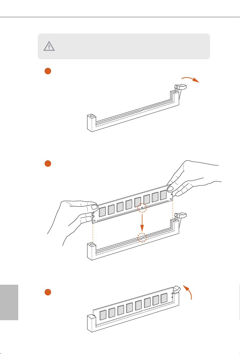
e DIMM only ts in one correct orientation. It will cause permanent damage to
the motherboard and the DIMM if you force the DIMM into the slot at incor rect
orientation.
1
2
English
3
22 23
Page 26
X300-ITX / X300-ITX/COM
2.4 Expansion Slot (PCIe Slot)
ere are 1 PCIe slot on the motherboard.
Before installing an ex pansion card, please make sure that the power supply is switched o
or the power cord is unplugged. Please re ad the documentation of the expansion card and
make necessary hardware settings for the card before you start the installation.
PCIe slot:
PCIE2 (PCIe 3.0 x16 slot) is used for PCIe x16 lane width graphics cards.
PCIe Slot Conguration
PCIE2
Ryzen series CPUs
(Vermeer, Matisse, Pinnacle Ridge)
Ryzen series APUs
(Cezanne, Renoir)
Ryzen series APUs
(Picasso, Raven Ridge)
Athlon series CPU Gen3x4
Gen3x16
Gen3x16
Gen3x8
English
Page 27
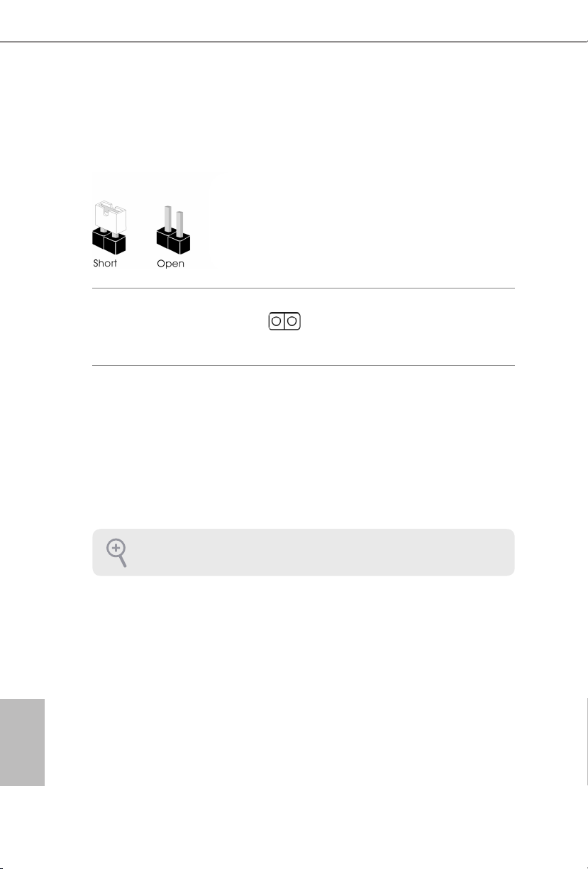
2.5 Jumpers Setup
e illustration shows how jumpers are setup. When the jumper cap is placed on
the pins, the jumper is “Short”. If no jumper cap is placed on the pins, the jumper is
“Open”.
English
Clear CMOS Jumper
(CLRCMO S1)
(see p.1, No. 13)
CLRCMOS1 allows you to clear the data in CMOS. e data in CMOS includes
system setup information such as system password, date, time, and system setup
parameters. To clear and reset the system parameters to default setup, please
turn o the computer and unplug the power cord, then use a jumper cap to short
the pins on CLRCMOS1 for 3 seconds. Please remember to remove the jumper
cap aer clearing the CMOS. If you need to clear the CMOS when you just nish
updating the BIOS, you must boot up the system rst, and then shut it down
before you do the clear-CMOS action.
If you clear the CMOS, the case open may be detec ted. Please adjust the BIOS option
“Clear Status” to clear the record of previou s chassis intrusion status.
2-pin Jumper
Short: Clear CMOS
Open: Default
24 25
Page 28
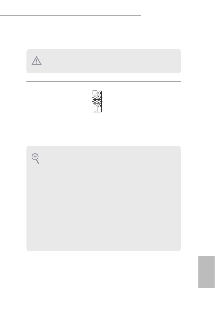
2.6 Onboard Headers and Connectors
#
HDLED
1
Onboard headers and connectors are NOT jumpers. Do NOT place jumper caps over these
heade rs and connectors. Placing jumper caps over the headers and connectors will cause
permanent damage to the motherboard.
X300-ITX / X300-ITX/COM
System Panel Header
(9-pi n PANEL1)
(see p.1, No.10)
PWRBTN (Power Button):
Connec t to the power button on the chassi s front panel. You may congure the way to tur n
o your system using the power button.
RESET (Reset B utton):
Connec t to the reset button on the chassi s front panel. Press the reset button to restart the
computer if the computer f reezes and fails to per form a normal restar t.
PLED (Syste m Power LED):
Connec t to the power status indicator on the chassis front panel. e LED i s on when the
system is operating. e LED keeps blinking when the system is in S1/S3 sleep state. e
LED is o when the system is in S4 slee p state or powered o (S5).
HDLED (Ha rd Drive Activity LED):
Connec t to the hard drive activity LED on the chassis front panel. e LED is on when the
hard drive is reading or wr iting data.
e front panel design may dier by chassis. A front panel module mainly consists of powe r
button, reset button , power LED, hard dr ive activity LED, speaker and etc. When connecting your chassi s front panel module to thi s header, make sure the wire a ssignments and the
pin assignments are matched correctly.
HDLED-
GND
GND
+
PLED+
PLED-
PWRBTN
GNDRESET#
Connect the power
button, reset button and
system status indicator on
the chassis to this header
according to the pin
assignments below. Note
the positive and negative
pins before connecting
the cables.
English
Page 29

Serial ATA3 Connector
DUMMY
GNDGND
P+P-P+
P-
USB_PWR
USB_PWR
1
L
1
2
3
4
1
DDSR#1
DDTR#1
RRXD#1
DDCD#
GND
1
(SATA3_1:
see p.1, No. 9)
(SATA3_2:
see p.1, No. 13)
SATA3_2
SATA3_1
ese two SATA3
connector supports SATA
data cables for internal
storage devices with up to
6.0 Gb/s data transfer rate.
USB 2.0 Header
(9-pin USB_5_6)
(see p.1, No. 8)
Chassis Fan Connector
(4-pin CHA_FAN1)
(see p.1, No. 11)
CPU Fan Connectors
(4-pin CPU_FAN1)
(see p.1, No. 3)
Serial Port Header
(9-pin COM1)
(see p.1, No.1)
(for X300-ITX/COM
only)
2
3
4
RRI#1
CCTS#1
RRTS#1
GND
TTXD#1
+12V
CHA_FAN_SPEED
FAN_SPEED_CONTROL
GN D
+ 12V
CPU_FAN_SPEED
FAN_SPEED_CONTRO
1
ere is one header on
this motherboard. is
USB 2.0 header can
support two ports.
Please connect fan cable
to the fan connector and
match the black wire to
the ground pin.
is motherboard
provides a 4-Pin CPU fan
(Quiet Fan) connector.
If you plan to connect a
3-Pin CPU fan, please
connect it to Pin 1-3.
is COM1 header
supports a serial port
module.
English
26 27
Page 30
X300-ITX / X300-ITX/COM
1
Signa
4
1
8 5
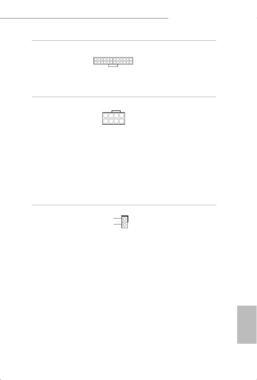
ATX Power Connector
(24-pin ATXPWR1)
(see p.1, No. 7)
ATX 12V Power
Connector
(8-pin ATX12V1)
(see p.1, No. 1)
Chassis Intrusion Header
(2-pin CI1)
(see p.1, No. 6)
is motherboard pro-
1
13
12
vides a 24-pin ATX power
connector. To use a 20-pin
24
ATX power supply, please
plug it along Pin 1 and Pin
13.
is motherboard
provides a 8-pin ATX 12V
power connectors. To use
a 4-pin ATX power
supply, please plug it along
Pin 1 and Pin 5.
*Warning: Please make
sure that the power cable
connected is for the CPU
and not the graphics
card. Do not plug the
PCIe power cable to this
connector.
GND
l
is motherboard
supports CASE OPEN
detection feature that
detects if the chassis cove
has been removed. is
feature requires a chassis
with chassis intrusion
detection design.
English
Page 31

2.7 M.2 WiFi/BT Module Installation Guide
e M.2, also known as the Next Generation Form Factor (NGFF), is a small size and
versatile card edge connector that aims to replace mPCIe and mSATA. e M.2 Socket (Key
E) supports type 2230 WiFi/BT module.
Installing the WiFi/BT module
Step 1
Prepare a type 2230 WiFi/BT module
and the screw.
Step 2
Find the nut location to be used.
PCB Length: 3cm
Module Type: Type2230
A
Step 3
Gently insert the WiFi/BT module
into the M.2 slot. Please be aware
that the module only ts in one
orientation.
A
English
o
A
20
28 29
Page 32

X300-ITX / X300-ITX/COM
Step 4
Tighten the screw with a screwdriver
to secure the module into place.
Please do not overtighten the screw as
this might damage the module.
A
English
Page 33

2.8 M.2_SSD (NGFF) Module Installation Guide
e M.2, also known as the Next Generation Form Factor (NGFF), is a small size and
versatile card edge connector that aims to replace mPCIe and mSATA. The Ultra M.2
Socket (M2_1) supports type 2280 M.2 PCI Express module up to Gen3 x4 (32 Gb/s)
or Gen3 x2 (16 Gb/s) (with Athlon 2xxGE series).
Installing the M.2_SSD (NGFF) Module
Step 1
Prepare a M.2_SSD (NGFF) module
and the screw.
Step 2
Gently insert the M.2 (NGFF) SSD
module into the M.2 slot. Please
be aware that the M.2 (NGFF) SSD
module only ts in one orientation.
o
20
Step 3
Tighten the screw with a
screwdriver to secure the
English
NUT1NUT2
module into place. Please do
not overtighten the screw as
this might damage the module.
30 31
Page 34

X300-ITX / X300-ITX/COM
M.2_SSD (NGFF) Module Support List
Vendor Interface P/N
ADATA PCIe ADATA ASX7000NPC-512GT-C (XPG SX7000) (NVMe)
ADATA PCIe ADATA ASX8000NPC-512GM-C (XPG ASX8000) (NVMe)
Apacer PCIe Apacer Z280 AP240GZ280-240G (NVMe)
Intel PCIe Intel Optane Memory 32GB (MEMPEK1W032GA)(NVMe)
Intel PCIe Intel Optane Memory 16GB (MEMPEK1W016GA)(NVMe)
INTEL PCIe INTEL 600P-SSDPEKKW256G7-256GB (NVMe)
INTEL PCIe INTEL 600P-SSDPEKKW128G7-128GB (NVMe)
INTEL PCIe INTEL 6000P-SSDPEKKF256G7-256GB (NVMe)
INTEL PCIe INTEL 6000P-SSDPEKKF512G7-512GB (NVMe)
Kingston PCIe Kingston SHPM2280P2/240G
PATR IOT PCIe PATRIOT Hellre M2 (240G) (NVMe)
PLEXTOR PCIe PLEXTOR PX-256M8PeG (NVMe)
PLEXTOR PCIe PLEXTOR PX-256M8SeGN (NVMe)
Samsung PCIe Samsung XP941-512G (MZHPU512HCGL)
Samsung PCIe Samsung 950Pro-512G (NVMe)
Samsung PCIe Samsung 950Pro-256G (NVMe)
Samsung PCIe Samsung MZ-VLW1280 (PM961) (NVMe)
Samsung PCIe Samsung MZ-VPW1280 (SM961) (NVMe)
TOSHIBA PCIe TOSHIBA XG3-128G (NVMe)
TOSHIBA PCIe TOSHIBA OCZ RD400-256G (NVMe)
WD PCIe WD W DS512G1X0C-00ENX0 (NVMe)
WD PCIe WD WDS256G1X0C-00ENX0 (NVMe)
For the latest updates of M.2_SSD (NFGG) module support list, please visit our website for
details.
English
Page 35

1 Einleitung
Vielen Dank für den Kauf des Motherboards X300-ITX / X300-ITX/COM. In dieser
Dokumentation enthalten Kapitel 1 und 2 die Motherboard-Vorstellung sowie Schritt-fürSchritt-Installationsanleitungen.
Da die technischen Daten des Motherboards sowie die BIOS-Soware aktualisiert werden können,
kann der Inhalt dieser Dokumentation ohne Ankündigung geändert werden.
1.1 Lieferumfang
X300-ITX / X300-ITX/COM-Motherboard (Tiefer Mini-ITX-Formfaktor)
•
X300-ITX / X300-ITX/COM-Schnellinstallationsanleitung
•
1 x E/A-Blendenabschirmung
•
2 x SATA-Kabel (optional)
•
1 x Schraube für M.2-Sockel (M2x2) (optional)
•
1 x Schraube für WLAN-Modul (M2x2) (optional)
•
Deutsch
32
Page 36

1.2 Technische Daten
Tiefer Mini-ITX-Formfaktor
Plattform
Prozessor
Chipsatz
Speicher
•
Feststoondensator-Design
•
Unterstützt AMD-AM4-Sockel für Desktop-Prozessoren der
•
Serie G RyzenTM 2000, 3000, 4000 G, 5000 und 5000 G
Unterstützt CPU bis 65 W
•
6-Leistungsphasendesign
•
AMD X300
•
Dualkanal-DDR4-Speichertechnologie
•
4 x DDR4-DIMM-Steckplätze
•
APU der AMD-Ryzen-Serie (Cezanne) unterstützen DDR4
•
3200/2933/2667/2400/2133 ECC und non-ECC, ungepuerter
Speicher*
Prozessoren der AMD-Ryzen-Serie (Vermeer) unterstützen DDR4
•
3200/2933/2667/2400/2133 ECC und non-ECC, ungepuerter
Speicher*
Prozessoren der AMD-Ryzen-Serie (Matisse) unterstützen DDR4
•
3200/2933/2667/2400/2133 ECC und non-ECC, ungepuerter
Speicher*
APU der AMD-Ryzen-Serie (Renoir) unterstützen DDR4
•
3200/2933/2667/2400/2133 ECC und non-ECC, ungepuerter
Speicher*
Prozessoren der AMD-Ryzen-Serie (Pinnacle Ridge) unterstützen
•
DDR4 2933/2667/2400/2133 ECC und non-ECC, ungepuerter
Speicher*
APU der AMD-Ryzen-Serie (Picasso) unterstützen DDR4
•
2933/2667/2400/2133 ECC und non-ECC, ungepuerter Speicher*
Prozessoren der AMD-Ryzen-Serie (Raven Ridge) unterstützen
•
DDR4 2933/2667/2400/2133 ECC und non-ECC, ungepuerter
Speicher*
* Für APUs der Ryzen-Serie (Cezanne, Renoir und Picasso), ECC wird
nur mit PRO-Prozessoren unterstützt.
X300-ITX / X300-ITX/COM
Deutsch
33
Page 37

* Bitte beachten Sie Seite 18 für die maximal unterstützte Frequenz von
DDR4-DIMM.
Systemspeicher, max. Kapazität: 128GB
•
15-μ-Goldkontakt in DIMM-Steckplätze
•
Deutsch
Erweiterungssteckplatz
Grakkarte
Prozessoren der AMD-Ryzen-Serie (Vermeer, Matisse, Pinnacle
Ridge)
1 x PCIe-Gen3x16-Steckplatz (x16-Modus)*
•
APU (Cezanne und Renoir) der AMD-Ryzen-Serie
1 x PCIe-Gen3x16-Steckplatz (x16-Modus)*
•
APU der AMD-Ryzen-Serie (Picasso, Raven Ridge)
1 x PCIe-Gen3x16-Steckplatz (x8-Modus)*
•
Prozessoren der AMD-Athlon-Serie
1 x PCIe-Gen3x16-Steckplatz (x4-Modus)*
•
* Unterstützt NVMe-SSD als Bootplatte
1 x M.2-Sockel (Key E), unterstützt Typ-2230-Wi-Fi-/-BT-Modul
•
Integrierte Grakkarte der AMD-RadeonTM-Vega-Serie in APU der
•
Ryzen-Serie*
* Tatsächliche Unterstützung kann je nach Prozessor variieren
DirectX 12, Pixel Shader 5.0
•
Freigabespeicher von standardmäßig 2GB. Max. Freigabespeicher
•
unterstützt bis zu 16GB.
* Der max. Freigabespeicher von 16GB erfordert die Installation von
32GB Systemspeicher.
Drei Grakkarten-Ausgangsoptionen: D-Sub, DisplayPort 1.2 und
•
HDMI
Unterstützt drei Monitore
•
Unterstützt HDMI mit maximaler Auösung von 4K x 2K (4096 x
•
2160) bei 60 Hz
Unterstützt D-Sub mit maximaler Auösung von 1920 x 1200 bei
•
60 Hz
Unterstützt DisplayPort 1.2 mit maximaler Auösung von 4K x 2K
•
(4096 x 2304) bei 60 Hz
Unterstützt Auto-Lippensynchronizität, hohe Farbtiefe (12 bpc),
•
xvYCC und HBR (Audio mit hoher Bitrate) mit HDMI-Port
(konformer HDMI-Monitor erforderlich)
Unterstützt HDCP mit HDMI- und DisplayPort 1.2-Ports
•
Unterstützt 4K-Ultra-HD- (UHD) Wiedergabe mit HDMI- und
•
DIsplayPort-1.2-Ports
34
Page 38

Audio
LAN
Frontblende,
E/A
X300-ITX / X300-ITX/COM
Realtek-ALC897-Audiocodec
•
Unterstützt Überspannungsschutz
•
1 x Kopörer-/Headset-Anschluss
•
1 x Line-Ausgang
•
PCIE-x1-Gigabit-LAN 10/100/1000 Mb/s
•
Realtek RTL8111H
•
Unterstützt Wake-On-LAN
•
Unterstützt Schutz gegen Blitzschlag/elektrostatische Entladung
•
Unterstützt energieezientes Ethernet 802.3az
•
Unterstützt PXE
•
1 x Kopörer-/Headset-Anschluss
•
2 x USB 3.2-Gen1 Type-A-Ports (unterstützt Schutz gegen
•
elektrostatische Entladung (Full Spike Protection))
1 x USB 3.2-Gen1 Type-C-Ports (unterstützt Schutz gegen
•
elektrostatische Entladung (Full Spike Protection))
2 x USB 2.0-Ports (unterstützt Schutz gegen elektrostatische
•
Entladung (Full Spike Protection))
Rückblende,
E/A
Speicher
Anschluss
1 x D-Sub-Port
•
1 x HDMI-Port
•
1 x DisplayPort 1.2
•
2 x USB 3.2-Gen1 Type-A-Ports (unterstützt Schutz gegen
•
elektrostatische Entladung (Full Spike Protection))
2 x USB 2.0-Ports (unterstützt Schutz gegen elektrostatische
•
Entladung (Full Spike Protection))
1 x RJ-45-LAN-Port mit LED (Aktivität/Verbindung-LED und
•
Geschwindigkeit-LED)
1 x Line-Ausgang
•
2 x SATA III 6,0 Gb/s mit Stromanschlüssen, unterstützen RAID
•
(RAID 0 und RAID 1), NCQ, AHCI und Hot-Plug
1 x Ultra-M.2-Steckplatz (M2_1), unterstützt Typ-2280-M.2-PCI-
•
Express-Modul bis Gen3 x4 (32 Gb/s) oder Gen3 x2 (16 Gb/s) (mit
Ahtlon 2xxGE-Serie)*
* Unterstützt NVMe-SSD als Bootplatte
1 x COM-Port-Stileiste (optional für X300-ITX/COM-Modell)
•
Deutsch
35
Page 39

BIOSFunktion
Hardwareüberwachung
1 x Gehäuseeingri-Stileiste
•
1 x CPU-Lüeranschluss
•
* Der CPU-Lüeranschluss unterstützt einen CPU-Lüer mit einer
maximalen Lüerleistung von 1 A (12 W).
1 x Gehäuselüeranschluss (4-polig)
•
* Der Gehäuselüeranschluss unterstützt einen Gehäuselüer mit einer
maximalen Lüerleistung von 1 A (12 W).
1 x 24-poliger ATX-Netzanschluss
•
1 x 8-poliger 12-V-Netzanschluss
•
1 x Frontblendenstileiste
•
1 x USB 2.0-Stileiste (unterstützt zwei USB 2.0-Ports) (unterstützt
•
Schutz gegen elektrostatische Entladung)
AMI-UEFI-Legal-BIOS mit Unterstützung grascher
•
Benutzerschnittstellen
Unterstützt „Plug-and-Play“
•
ACPI 5.1-konforme Aufweckereignisse
•
Unterstützt Jumper-frei
•
SMBIOS 2.3-Unterstützung
•
DRAM-Spannungsanpassung
•
CPU-/Gehäusetemperaturerkennung
•
CPU-/Gehäuselüertachometer
•
Lautloser CPU-/Gehäuselüer (automatische Anpassung der
•
Gehäuselüergeschwindigkeit durch CPU-Temperatur)
CPU/Gehäuselüer-Mehrfachgeschwindigkeitssteuerung
•
Gehäuse-oen-Erkennung
•
Spannungsüberwachung: +12 V, +5 V, +3,3 V, CPU Vcore
•
Deutsch
36
Microso® Windows® 10, 64 Bit
Betriebs-
•
system
FCC, CE
Zertizierungen
Bitte beachten Sie, dass mit einer Übertaktung, zu der die Anpassung von BIOS-Einstellungen, die
Anwendung der Untied Overclocking Technology oder die Nutzung von Übertaktungswerkzeugen
von Drittanbietern zählen, bestimmte Risiken verbunden sind. Eine Übertaktung kann sich auf die
Stabilität Ihres Systems auswirken und sogar Komponenten und Geräte Ihres Systems beschädigen.
Sie sollte auf eigene Gefahr und eigene Kosten durchgeführt werden. Wir übernehmen keine
Verantwortung für mögliche Schäden, die durch eine Übertaktung verursacht wurden.
•
ErP/EuP ready (ErP/EuP ready-Netzteil erforderlich)
•
Page 40

X300-ITX / X300-ITX/COM
1.3 Jumpereinstellung
Die Abbildung zeigt, wie die Jumper eingestellt werden. Wenn die Jumper-Kappe auf den
Kontakten angebracht ist, ist der Jumper „kurzgeschlossen“. Wenn keine Jumper-Kappe auf
den Kontakten angebracht ist, ist der Jumper „oen“.
CMOS-löschen-Jumper
(CLRCMOS1)
(siehe S. 1, Nr. 13)
CLRCMOS1 ermöglicht Ihnen die Löschung der Daten im CMOS. Die Daten im CMOS
beinhaltet Systemeinrichtungsinformationen, wie Systemkennwort, Datum, Zeit und
Systemeinrichtungsparameter. Zum Löschen und Rücksetzen der Systemparameter auf
die Standardeinrichtung schalten Sie den Computer bitte ab und ziehen das Netzkabel;
schließen Sie dann die Kontakte an CLRCMOS1 3 Sekunden mit einer Jumper-Kappe kurz.
Bitte denken Sie daran, die Jumper-Kappe nach der CMOS-Löschung zu entfernen. Falls
Sie den CMOS direkt nach Abschluss der BIOS-Aktualisierung löschen müssen, starten Sie
das System zunächst; fahren Sie es dann vor der CMOS-Löschung herunter.
Falls Sie den CMOS löschen, wird möglicherweise ein Gehäuseeingri erkannt. Bitte passen
Sie die BIOS-Option „Status löschen“ zur Löschung der Aufzeichnung des vorherigen
Gehäuseeingristatus an.
2-poliger Jumper
Kurzgeschlossen: CMOS löschen
Oen: Standard
Deutsch
37
Page 41

1.4 Integrierte Stiftleisten und Anschlüsse
#
HDLED
1
Integrierte Stileisten und Anschlüsse sind KEINE Jumper. Bringen Sie KEINE Jumper-Kappen an
diesen Stileisten und Anschlüssen an. Durch Anbringen von Jumper-Kappen an diesen Stileisten
und Anschlüssen können Sie das Motherboard dauerha beschädigen.
Systemblende-Stileiste
(9-polig, PANEL1)
(siehe S. 1, Nr. 10)
PWRBTN (Ein-/Austaste):
Mit der Ein-/Austaste an der Frontblende des Gehäuses verbinden. Sie können die Abschaltung Ihres
Systems über die Ein-/Austaste kongurieren.
RESET (Reset-Taste):
Mit der Reset-Taste an der Frontblende des Gehäuses verbinden. Starten Sie den Computer über die
Reset-Taste neu, wenn er abstürzt oder sich nicht normal neu starten lässt.
PLED (Systembetriebs-LED):
Mit der Betriebsstatusanzeige an der Frontblende des Gehäuses verbinden. Die LED leuchtet, wenn
das System läu. Die LED blinkt, wenn sich das System im S1/S3-Ruhezustand bendet. Die LED ist
aus, wenn sich das System im S4-Ruhezustand bendet oder ausgeschaltet ist (S5).
HDLED (Festplattenaktivitäts-LED):
Mit der Festplattenaktivitäts-LED an der Frontblende des Gehäuses verbinden. Die LED leuchtet,
wenn die Festplatte Daten liest oder schreibt.
Das Design der Frontblende kann je nach Gehäuse variieren. Ein Frontblendenmodul besteht
hauptsächlich aus Ein-/Austaste, Reset-Taste, Betrieb-LED, Festplattenaktivität-LED, Lautsprecher
etc. Stellen Sie beim Anschließen Ihres Frontblendenmoduls an diese Stileiste sicher, dass Kabel- und
Pinbelegung richtig abgestimmt sind.
HDLED-
GND
GND
+
PLED+
PLED-
PWRBTN
GNDRESET#
Verbinden Sie Ein-/Austaste,
Reset-Taste und
Systemstatusanzeige am Gehäuse
entsprechend der nachstehenden
Pinbelegung mit dieser Stileiste.
Beachten Sie vor Anschließen der
Kabel die positiven und negativen
Kontakte.
Deutsch
38
Page 42

X300-ITX / X300-ITX/COM
DUMMY
GNDGND
P+P-P+
P-
USB_PWR
USB_PWR
1
GND
+12V
CHA_FAN_SPEED
FAN_SPEED_CONTROL
1
2
3
4
L
1
2
3
4
DDSR#1
RRXD#1
DDCD#
Serial-ATA-III-Anschluss
(SATA3_1:
siehe S. 1, Nr. 9)
(SATA3_2:
siehe S. 1, Nr. 13)
USB 2.0-Stileiste
(9-polig, USB_5_6)
(siehe S. 1, Nr. 8)
Gehäuselüeranschluss
(4-polig, CHA_FAN1)
(siehe S. 1, Nr. 11)
CPU-Lüeranschlüsse
(4-polig, CPU_FAN1)
(siehe S. 1, Nr. 3)
SATA3_1SATA3_2
GN D
+ 12V
CPU_FAN_SPEED
FAN_SPEED_CONTRO
Diese beiden SATA-III-Anschlüsse
unterstützen SATA-Datenkabel
für interne Speichergeräte mit
einer Datenübertragungsgeschwindigkeit bis 6,0 Gb/s.
Es gibt eine Stileiste an diesem
Motherboard. Diese USB 2.0Stileiste unterstützt zwei Ports.
Bitte verbinden Sie das Lüerkabel
mit dem Lüeranschluss; der
schwarze Draht gehört zum
Erdungskontakt.
Dieses Motherboard bietet einen
4-poligen CPU-Lüeranschluss
(lautloser Lüer). Falls Sie einen
3-poligen CPU-Lüer anschließen
möchten, verbinden Sie ihn bitte
mit Kontakt 1 bis 3.
Serieller-Port-Stileiste
(9-polig, COM1)
(siehe S. 1, Nr. 1)
(nur für X300-ITX/COM)
RRI#1
CCTS#1
RRTS#1
GND
DDTR#1
TTXD#1
1
Diese COM1-Stileiste unterstützt
ein Modul für serielle Ports.
1
Deutsch
39
Page 43

ATX-Netzanschluss
4
1
8 5
1
Signa
(24-polig, ATXPWR1)
(siehe S. 1, Nr. 7)
1
12
Dieses Motherboard bietet einen
24-poligen ATX-Netzanschluss.
Bitte schließen Sie es zur Nutzung
13
24
eines 20-poligen ATX-Netzteils
entlang Kontakt 1 und Kontakt 13
an.
ATX-12-V-Netzanschluss
(8-polig, ATX12V1)
(siehe S. 1, Nr. 1)
Gehäuseeingri-Stileiste
(2-polig, CI1)
(siehe S. 1, Nr. 6)
GND
Dieses Motherboard bietet
einen 8-poligen ATX-12-VNetzanschluss. Bitte schließen Sie
es zur Nutzung eines 4-poligen
ATX-Netzteils entlang Kontakt 1
und Kontakt 5 an.
*Warnung: Bitte stellen Sie sicher,
dass das Stromkabel der CPU
und nicht das der Grakkarte
angeschlossen ist. Schließen Sie
das PCIe-Stromkabel nicht an
diesen Anschluss an.
Dieses Motherboard unterstützt
l
die Gehäuse-oen-Erkennung,
die erkennt, wenn die Gehäuseabdeckung entfernt wurde. Diese
Funktion setzt ein Gehäuse mit
Gehäuseeingrierkennungsdesign
voraus.
Deutsch
40
Page 44

X300-ITX / X300-ITX/COM
1 Introduction
Merci d'avoir acheté cette carte mère X300-ITX / X300-ITX/COM. Dans cette
documentation, les Chapitres 1 et 2 sont consacrés à la présentation de la carte mère et à son
installation étape par étape.
Les spécications de la carte mère et du logiciel BIOS pouvant être mises à jour, le contenu de ce
document est soumis à modication sans préavis.
1.1 Contenu de l’emballage
Carte mère X300-ITX / X300-ITX/COM (Facteur de forme Deep mini-ITX)
•
Guide d’installation rapide X300-ITX / X300-ITX/COM
•
1 x panneau de protection E/S
•
2 x câbles SATA (optionnel)
•
1 x vis pour socket M.2 (M2*2) (optionnel)
•
1 x vis pour module Wi-Fi (M2*2) (optionnel)
•
41
Français
Page 45

Français
1.2 Spécications
Facteur de forme Deep mini-ITX
Plateforme
Processeur
Chipset
Mémoire
•
Conception à condensateurs solides
•
Prend en charge les processeurs de bureau AMD AM4 socket
•
RyzenTM 2000, 3000, 4000 G Series, 5000 et 5000 G Series
Prend en charge les unités centrales jusqu’à 65W
•
Alimentation à 6 phases
•
AMD X300
•
Technologie mémoire double canal DDR4
•
4 x fentes DIMM DDR4
•
Les APU AMD série Ryzen (Cezanne) prennent en charge
•
les mémoires sans tampon ECC et non ECC DDR4
3200/2933/2667/2400/2133*
Les processeurs AMD série Ryzen (Vermeer) prennent en
•
charge les mémoires sans tampon ECC et non ECC DDR4
3200/2933/2667/2400/2133*
Les processeurs AMD série Ryzen (Matisse) prennent en
•
charge les mémoires sans tampon ECC et non ECC DDR4
3200/2933/2667/2400/2133*
Les APU AMD série Ryzen (Renoir) prennent en charge
•
les mémoires sans tampon ECC et non ECC DDR4
3200/2933/2667/2400/2133*
Les processeurs AMD série Ryzen (Pinnacle Ridge) prennent
•
en charge les mémoires sans tampon ECC et non ECC DDR4
2933/2667/2400/2133*
Les APU AMD série Ryzen (Picasso) prennent en charge
•
les mémoires sans tampon ECC et non ECC DDR4
2933/2667/2400/2133*
Les processeurs AMD série Ryzen (Raven Ridge) prennent
•
en charge les mémoires sans tampon ECC et non ECC DDR4
2933/2667/2400/2133*
* Sur les APU série Ryzen (Cezanne, Renoir et Picasso), ECC est pris
en charge uniquement avec les processeurs PRO.
42
Page 46

X300-ITX / X300-ITX/COM
* Veuillez consulter la page 18 pour connaître la prise en charge de la
fréquence maximale de l'DIMM DDR4.
Capacité max. de la mémoire système : 128GO
•
Contacts dorés 15μ sur fentes DIMM
•
Fente
d’expansion
Graphiques
Processeurs AMD série Ryzen (Vermeer, Matisse, Pinnacle Ridge)
1 x emplacement PCIe Gen3x16 (mode x16)*
•
APU AMD série Ryzen (Cezanne, Renoir)
1 x emplacement PCIe Gen3x16 (mode x16)*
•
APU AMD série Ryzen (Picasso, Raven Ridge)
1 x emplacement PCIe Gen3x16 (mode x8)*
•
Processeurs AMD Athlon série
1 x emplacement PCIe Gen3x16 (mode x4)*
•
* Prend en charge les SSD NVMe comme disques de démarrage
1 x socket M.2 (Touche E), prend en charge les modules WiFi/BT
•
type 2230
Carte graphique AMD RadeonTM série Vega intégrée dans APU
•
série Ryzen*
* La prise en charge réelle peut varier selon le processeur
DirectX 12, Pixel Shader 5.0
•
Mémoire partagée par défaut 2Go. Mémoire partagée maximum
•
prise en charge 16Go.
* La mémoire partagée maximum de 16Go nécessite 32Go de
mémoire système installée.
Trois options de sortie graphique : D-Sub, DisplayPort 1.2 et HDMI
•
Prend en charge la conguration à triple moniteurs
•
Prend en charge la technologie HDMI avec résolution maximale de
•
4K × 2K (4096x2160) @ 60Hz
Prend en charge le mode D-Sub avec une résolution maximale de
•
1920x1200 @ 60Hz
Prend en charge la technologie DisplayPort 1.2 avec résolution
•
maximale de 4K × 2K (4096x2304) @ 60Hz
Prend en charge les technologies Auto Lip Sync, Deep Color
•
(12bpc), xvYCC et HBR (High Bit Rate Audio) avec port HDMI
(un écran compatible HDMI est requis)
Prend en charge HDCP via ports HDMI et DisplayPort 1.2
•
Prend en charge la lecture 4K Ultra HD (UHD) avec les ports
•
HDMI et DisplayPort 1.2
Français
43
Page 47

Français
Audio
Réseau
Connectique
E/S du
panneau
avant
Connectique
du panneau
arrière
Stockage
Codec audio Realtek ALC897
•
Prend en charge la protection contre les surtensions
•
1 x sortie casque téléphonique/casque d’écoute
•
1 x prise sortie ligne
•
PCIE x1 Gigabit LAN 10/100/1000 Mo/s
•
Realtek RTL8111H
•
Prend en charge la fonction Wake-On-LAN
•
Prend en charge la protection contre la foudre/les décharges
•
électrostatiques
Prend en charge la fonction d’économie d’énergie Ethernet 802.3az
•
Prend en charge PXE
•
1 x sortie casque téléphonique/casque d’écoute
•
2 x ports USB 3.2 Gen1 Type-A (Protection contre les décharges
•
électrostatiques (Protection complète contre les pics))
1 x ports USB 3.2 Gen1 Type-C (Protection contre les décharges
•
électrostatiques (Protection complète contre les pics))
2 x ports USB 2.0 (Protection contre les décharges électrostatiques
•
(Protection complète contre les pics))
1 x port D-Sub
•
1 x port HDMI
•
1 x DisplayPort 1.2
•
2 x ports USB 3.2 Gen1 Type-A (Protection contre les décharges
•
électrostatiques (Protection complète contre les pics))
2 x ports USB 2.0 (Protection contre les décharges électrostatiques
•
(Protection complète contre les pics))
1 x port RJ-45 LAN avec LED (LED ACT/LIEN et LED VITESSE)
•
1 x prise sortie ligne
•
2 x SATA3 6,0 Go/s avec connecteurs d’alimentation, prise en
•
charge de RAID (RAID 0 et RAID 1), NCQ, AHCI et branchement
à chaud
1 x socket Ultra M.2 (M2_1), prend en charge les modules PCI
•
Express M.2 type 2280 jusqu’à Gen3 x4 (32 Go/s) ou Gen3 x2
(16 Go/s) (avec Athlon série 2xxGE)*
* Prend en charge les SSD NVMe comme disques de démarrage
44
Connecteur
1 x embase de port COM (optionnel sur modèle X300-ITX/COM)
•
Page 48

Caractéristiques du
BIOS
Surveillance
du matériel
X300-ITX / X300-ITX/COM
1 x embase d’intrusion châssis
•
1 x connecteur pour ventilateur de processeur
•
* Le connecteur pour ventilateur de CPU prend en charge un
ventilateur de CPU d'une puissance maximale de 1 A (12 W).
1 x connecteur pour ventilateur de châssis (4 broches)
•
* Le connecteur pour ventilateur de châssis prend en charge un
ventilateur de châssis d'une puissance maximale de 1 A (12 W).
1 x connecteur d’alimentation ATX 24 broches
•
1 x connecteur d’alimentation 12V 8 broches
•
1 x Panneau avant
•
1 x embase USB 2.0 (2 ports USB 2.0 pris en charge) (Protection
•
contre les décharges électrostatiques)
BIOS UEFI AMI avec prise en charge d’interface graphique
•
Prend en charge la fonction «Plug and Play»
•
Compatible ACPI 5.1 Wake Up Events
•
Prend en charge la conguration Jumpfree
•
Compatible SMBIOS 2.3
•
Réglage de la tension DRAM
•
Détection de la température du processeur/châssis
•
Tachéomètre ventilateur processeur/châssis
•
Ventilateur silencieux processeur/châssis (réglage automatique
•
de la vitesse du ventilateur du châssis d’après la température du
processeur)
Contrôle simultané des vitesse du ventilateur processeur/châssis
•
Détection CHÂSSIS OUVERT
•
Surveillance de la tension d’alimentation : +12V, +5V, +3,3V, CPU
•
Vcore
Microso® Windows® 10 64 bits
Système
•
d’exploitation
FCC, CE
Certications
Il est important de signaler que l’overclocking présente certains risques, incluant des modications
du BIOS, l’application d’une technologie d’overclocking déliée et l’utilisation d’outils d’overclocking
développés par des tiers. La stabilité de votre système peut être aectée par ces pratiques, voire
provoquer des dommages aux composants et aux périphériques du système. L’overclocking se fait
à vos risques et périls. Nous ne pourrons en aucun cas être tenus pour responsables des dommages
éventuels provoqués par l’overclocking.
•
ErP/EuP Ready (alimentation ErP/EuP ready requise)
•
Français
45
Page 49

1.3 Conguration des cavaliers (jumpers)
L’illustration ci-dessous vous renseigne sur la conguration des cavaliers (jumpers). Lorsque
le capuchon du cavalier est installé sur les broches, le cavalier est «court-circuité». Si le
capuchon du cavalier n’est pas installé sur les broches, le cavalier est «ouvert».
Français
Cavalier Clear CMOS
(CLRCMOS1)
(voir p.1, No. 13)
CLRCMOS1 vous permet d’eacer les donnés de la CMOS. Les données de la CMOS
incluent les informations de conguration du système telles que mot de passe, date,
heure et paramètres de réglage du système. Pour eacer les paramètres du système et
rétablir les valeurs par défaut, veuillez éteindre votre ordinateur et débrancher son cordon
d’alimentation; utilisez ensuite un capuchon de cavalier pour court-circuiter les broches
CLRCMOS1 pendant 3 secondes. N’oubliez pas de retirer le capuchon du cavalier une fois
les données CMOS eacées. Si vous avez besoin d’eacer les données CMOS après une mise
à jour du BIOS, vous devez tout d’abord redémarrer le système, puis l’éteindre avant de
procéder à l’eacement de la CMOS.
Si vous eacez la CMOS, l’alerte de châssis ouvert peut se déclencher. Veuillez régler l’option du
BIOS sur «Eacer » pour supprimer l’historique des intrusions de châssis précédentes.
Cavalier (jumper) à
2 broches
Court-circuité: Fonction Clear
CMOS
Ouvert: Par défaut
46
Page 50

1.4 Embases et connecteurs de la carte mère
#
HDLED
Les embases et connecteurs situés sur la carte NE SONT PAS des cavaliers. Ne placez JAMAIS de
capuchons de cavaliers sur ces embases ou connecteurs. Placer un capuchon de cavalier sur ces
embases ou connecteurs endommagera irrémédiablement votre carte mère.
X300-ITX / X300-ITX/COM
Embase du panneau
système
(PANNEAU1 à 9 broches)
(voir p.1, No.10)
PWRBTN (bouton d’alimentation) :
pour brancher le bouton d’alimentation du panneau frontal du châssis. Vous pouvez congurer la
façon dont votre système doit s’arrêter à l’aide du bouton d'alimentation.
RESET (bouton de réinitialisation) :
pour brancher le bouton de réinitialisation du panneau frontal du châssis. Appuyez sur le bouton
de réinitialisation pour redémarrer l’ordinateur en cas de plantage ou de dysfonctionnement au
démarrage.
PLED (LED d’alimentation du système) :
pour brancher le témoin d’état de l’alimentation du panneau frontal du châssis. Le LED est allumé
lorsque le système fonctionne. Le LED clignote lorsque le système se trouve en mode veille S1/S3. Le
LED est éteint lorsque le système se trouve en mode veille S4 ou hors tension (S5).
HDLED (LED d’activité du disque dur) :
pour brancher le témoin LED d’activité du disque dur du panneau frontal du châssis. Le LED est
allumé lorsque le disque dur lit ou écrit des données.
La conception du panneau frontal peut varier en fonction du châssis. Un module de panneau frontal
est principalement composé d’un bouton d'alimentation, d'un bouton de réinitialisation, d'un témoin
LED d’alimentation, d'un témoin LED d’activité du disque dur, d'un haut-parleur etc. Lorsque vous
reliez le module du panneau frontal de votre châssis sur cette embase, veillez à parfaitement faire
correspondre les ls et les broches.
HDLED-
GND
GND
1
+
PLED+
PLED-
PWRBTN
GNDRESET#
Branchez le bouton de mise
en marche, le bouton de
réinitialisation et le témoin d’état
du système présents sur le châssis
sur cette embase en respectant la
conguration des broches illustrée
ci-dessous. Repérez les broches
positive et négative avant de
brancher les câbles.
Français
47
Page 51

Connecteur Serial ATA3
DUMMY
GNDGND
P+P-P+
P-
USB_PWR
USB_PWR
1
GND
+12V
CHA_FAN_SPEED
FAN_SPEED_CONTROL
1
2
3
4
L
1
2
3
4
DDCD#
(SATA3_1:
voir p.1, No. 9)
(SATA3_2:
voir p.1, No. 13)
SATA3_1SATA3_2
Ces deux connecteurs SATA3
prennent en charge les câbles
de données SATA pour les
périphériques internes de stockage
avec des taux de transfert de
données allant jusqu'à 6,0 Go/s.
Français
Embase USB 2.0
(USB_5_6 à 9 broches)
(voir p.1, No. 8)
Connecteur du ventilateur
du châssis
(CHA_FAN1 à 4 broches)
(voir p.1, No. 11)
Connecteurs du
ventilateur du processeur
(CPU_FAN1 à 4 broches)
(voir p.1, No. 3)
Embase pour port série
(COM1 à 9 broches)
(voir p.1, No.1)
(sur X300-ITX/COM
uniquement)
GN D
+ 12V
CPU_FAN_SPEED
FAN_SPEED_CONTRO
1
RRI#1
CCTS#1
RRTS#1
DDSR#1
GND
DDTR#1
TTXD#1
RRXD#1
1
Cette carte mère comprend un
connecteur. Cette embase USB2.0
peut prendre en charge deux ports.
Veuillez brancher les câbles du
ventilateur sur le connecteur du
ventilateur, puis reliez le l noir à
la broche de mise à terre.
Cette carte mère est dotée d’un
connecteur pour ventilateur de
processeur (Quiet Fan) à
4 broches. Si vous envisagez
de connecter un ventilateur de
processeur à 3 broches, veuillez le
brancher sur la broche 1-3.
Cette embase COM1 prend en
charge un module de port série.
48
Page 52

X300-ITX / X300-ITX/COM
4
1
8 5
1
Signa
Connecteur d’alimentation
ATX
(ATXPWR1 à 24 broches)
(voir p.1, No. 7)
Connecteur d’alimentation
ATX 12 V
(ATX12V1 à 8 broches)
(voir p.1, No. 1)
Embase d’intrusion
châssis
(CI1 à 2 broches)
(voir p.1, No. 6)
1
12
Cette carte mère est dotée d’un
connecteur d’alimentation
ATX à 24 broches. Pour utiliser
13
24
une alimentation ATX à
20broches, veuillez eectuer les
branchements sur la Broche 1 et
la Broche 13.
Cette carte mère est dotée d’un
connecteur d’alimentation ATX
12 V à 8 broches. Pour utiliser une
alimentation ATX à 4 broches,
veuillez eectuer les branchements
sur la Broche 1 et la Broche 5.
*Avertissement : Veuillez vérier
que le câble d'alimentation
connecté est pour l'unité
centrale et non pour la carte
graphique. Ne branchez pas le
câble d'alimentation PCIe sur ce
connecteur.
GND
l
Cette carte mère prend en charge
la fonction de détection CHASSIS
OUVERT qui alerte l’utilisateur en
cas de retrait du boîtier du châssis.
Cette fonction requiert un châssis
à conception intégrant la détection
d’intrusion.
Français
49
Page 53

1 Introduzione
Congratulazioniii per l'acquisto della scheda madre X300-ITX / X300-ITX/COM. In
questo manuale, i capitoli 1 e 2 contengono un'introduzione alla scheda madre e le guide di
installazione passo passo.
Dato che le speciche della scheda madre e del soware BIOS possono essere aggiornate, il contenuto
di questa documentazione sarà soggetto a variazioni senza preavviso.
1.1 Contenuto della confezione
Scheda madre X300-ITX / X300-ITX/COM (Form factor Deep mini-ITX)
•
Guida rapida di installazione X300-ITX / X300-ITX/COM
•
1 x mascherina metallica posteriore I/O
•
2 x cavi di SATA (opzionali)
•
1 x vite per M.2 Socket (M2 x 2) (opzionali)
•
1 x vite per modulo WiFi (M2 x 2) (opzionali)
•
Italiano
50
Page 54

1.2 Speciche
Piattaforma
CPU
Chipset
Memoria
X300-ITX / X300-ITX/COM
Form factor Deep mini-ITX
•
Design condensatore solido
•
Supporta processori desktop socket AMD AM4 RyzenTM serie 2000,
•
3000, 4000 G, 5000 e 5000 G*
Supporto di CPU no a 65W
•
Potenza a 6 fasi
•
AMD X300
•
Tecnologia memoria DDR4 Dual Channel
•
4 x alloggi DIMM DDR4
•
Le APU serie AMD Ryzen (Cezanne) supportano DDR4
•
3200/2933/2667/2400/2133 ECC e non ECC, senza buer*
Le CPU serie AMD Ryzen (Vermeer) supportano DDR4
•
3200/2933/2667/2400/2133 ECC e non ECC, senza buer*
Le CPU serie AMD Ryzen (Matisse) supportano DDR4
•
3200/2933/2667/2400/2133 ECC e non ECC, senza buer*
Le APU serie AMD Ryzen (Renoir) supportano DDR4
•
3200/2933/2667/2400/2133 ECC e non ECC, senza buer*
Le CPU serie AMD Ryzen (Pinnacle Ridge) supportano DDR4
•
2933/2667/2400/2133 ECC e non ECC, senza buer*
Le CPU serie AMD Ryzen (Picasso) supportano DDR4
•
2933/2667/2400/2133 ECC e non ECC, senza buer*
Le CPU serie AMD Ryzen (Raven Ridge) supportano DDR4
•
2933/2667/2400/2133 ECC e non ECC, senza buer*
* Per le APU serie Ryzen (Cezanne, Renoir e Picasso), è supportata
solo la memoria ECC senza CPU PRO.
51
Italiano
Page 55

* Fare riferimento a pagina 18 per il supporto della frequenza massima
DDR4 DIMM.
Capacità max. della memoria di sistema: 128GB
•
Contatti d’oro 15μ negli alloggi DIMM
•
Italiano
Alloggio
d’espansione
Graca
CPU serie AMD Ryzen (Vermeer, Matisse, Pinnacle Ridge)
1 x alloggio PCIe Gen3x16 (modalità x16)*
•
APU serie AMD Ryzen (Cezanne e Renoir)
1 x alloggio PCIe Gen3x16 (modalità x16)*
•
APU serie AMD Ryzen (Picasso, Raven Ridge)
1 x alloggio PCIe Gen3x16 (modalità x8)*
•
CPU serie AMD Athlon
1 x alloggio PCIe Gen3x16 (modalità x4)*
•
* Supporto di SSD NVMe come disco d’avvio
1 x Socket M.2 (tastoE), supporta moduli di tipo 2230 WiFi/BT
•
Graca AMD RadeonTM serie Vega integrata nelle APU serie Ryzen*
•
* Il supporto eettivo può variare in base alla CPU
DirectX 12, Pixel Shader 5.0
•
Memoria condivisa predenita 2GB. Memoria condivisa massima
•
supporta no a 16GB.
* La memoria condivisa massima di 16GB richiede che sia installata
una memoria di sistema da 32GB.
Tre opzioni di output graco: D-Sub, DisplayPort 1.2 e HDMI
•
Supporto di tre monitor
•
Supporta HDMI con risoluzione massima no a 4K x 2K (4096 x
•
2160) a 60 Hz
Supporta D-Sub con una risoluzione max. no a 1920 x 1200 a
•
60 Hz
Supporta DisplayPort 1.2 con risoluzione massima no a 4K x 2K
•
(4096x2304) a 60 Hz
Supporto delle funzioni Auto Lip Sync, Deep Color (12bpc),
•
xvYCC e HBR (High Bit Rate Audio) con porta HDMI
(è necessario un monitor compatibile HDMI)
Supporto HDCP con le porte HDMI e DisplayPort 1.2
•
Supporto riproduzione 4K Ultra HD (UHD) sulle porte HDMI e
•
DisplayPort 1.2
52
Page 56

Audio
LAN
Pannello I/O
frontale
X300-ITX / X300-ITX/COM
Codec audio Realtek ALC897
•
Supporta protezione da sovratensione
•
1 x connettore cue/auricolare
•
1 x connettore uscita linea
•
1 x PCIE LAN Gigabit 10/100/1000 Mb/s
•
Realtek RTL8111H
•
Supporto WOL (Wake-On-LAN)
•
Supporta protezione da fulmini/scariche elettrostatiche
•
Supporto Energy Ecient Ethernet 802.3az
•
Supporto PXE
•
1 x connettore cue/auricolare
•
2 x Porte USB 3.2 Gen1 di Type-A (supporto protezione da scariche
•
elettrostatiche (ESD) (protezione completa dai picchi di corrente))
1 x Porte USB 3.2 Gen1 di Type-C (supporto protezione da scariche
•
elettrostatiche (ESD) (protezione completa dai picchi di corrente))
2 x Porte USB 2.0 (supporto protezione da scariche elettrostatiche
•
(ESD) (protezione completa dai picchi di corrente))
I/O pannello
posteriore
Archiviazione
Connettore
1 x porta D-Sub
•
1 x porta HDMI
•
1 x DisplayPort 1.2
•
2 x Porte USB 3.2 Gen1 di Type-A (supporto protezione da scariche
•
elettrostatiche (ESD) (protezione completa dai picchi di corrente))
2 x porte USB 2.0 (supporto protezione da scariche elettrostatiche
•
(ESD) (protezione completa dai picchi di corrente))
1 x porta LAN RJ-45 con LED (ACT/LINK LED e SPEED LED)
•
1 x connettore uscita linea
•
2 x SATA3 6,0 Gb/s con connettori di alimentazione, supporto di
•
RAID (RAID 0 e RAID 1), NCQ, AHCI e hot plug
1 x presa Ultra M.2 (M2_1), supporta il modulo PCI Express tipo
•
2280 M.2 no a Gen3 x4 (32 Gb/s) o Gen3 x2 (16 Gb/s) (con serie
Athlon 2xxGE)*
* Supporto di SSD NVMe come disco d’avvio
1 x collettore porta COM (opzionale per il modello X300-ITX/
•
COM)
Italiano
53
Page 57

Funzionalità
BIOS
Hardware
Monitor
1 x connettore intrusione telaio
•
1 x connettore ventola CPU
•
* Il connettore ventola CPU supporta ventole CPU con potenza
massima di 1 A (12 W).
1 x connettore ventola telaio (4-pin)
•
* Il connettore ventola telaio supporta ventole telaio con potenza
massima di 1 A (12 W).
1 x connettore alimentazione ATX 24-pin
•
1 x connettore alimentazione 12 V 8-pin
•
1 x connettore pannello frontale
•
1 x connettore USB 2.0 (supporto di 2 porte USB 2.0) (supporto
•
protezione da scariche elettrostatiche)
AMI UEFI Legal BIOS con interfaccia di supporto
•
Supporta “Plug and Play”
•
Eventi di riattivazione conformi a ACPI 5.1
•
Supporta jumperfree
•
Supporto di SMBIOS 2.3
•
Regolazione tensione DRAM
•
Sensore temperatura CPU/chassis
•
Tachimetro ventola CPU/telaio
•
Ventola silenziosa CPU/telaio (regolazione automatica velocità in
•
base alla temperatura della CPU)
Controllo multivelocità della ventola di CPU/chassis
•
Rilevamento CASE OPEN
•
Monitoraggio tensione: +12 V, +5 V, +3,3 V, CPU Vcore
•
Italiano
54
Microso® Windows® 10 64 bit
SO
Certicazioni
Prestare attenzione al potenziale rischio previsto nella pratica di overclocking, inclusa la regolazione
delle impostazioni nel BIOS, l'applicazione di tecnologia di Untied Overclocking o l'utilizzo di
strumenti di overclocking di terze parti. L'overclocking può inuenzare la stabilità del sistema o
perno provocare danni ai componenti e ai dispositivi del sistema. Occorre eseguirlo a proprio rischio
e spese. Non ci riterremo responsabili per possibili danni provocati da overclocking.
•
FCC, CE
•
ErP/EuP Ready (è necessaria alimentazione ErP/EuP ready)
•
Page 58

X300-ITX / X300-ITX/COM
1.3 Impostazione jumper
L'illustrazione mostra in che modo vengono impostati i jumper. Quando il cappuccio del
jumper è posizionato sui pin, il jumper è "cortocircuitato". Se sui pin non è posizionato alcun
cappuccio del jumper, il jumper è "aperto".
Jumper per azzerare la
CMOS
(CLRCMOS1)
(vedere pag. 1, n. 13)
CLRCMOS1 consente di azzerare i dati presenti nella CMOS. I dati presenti nella CMOS
includono informazioni relative all'impostazione del sistema quali password del sistema,
data, ora e parametri di impostazione del sistema. Per azzerare e reimpostare i parametri
del sistema alla congurazione predenita, spegnere il computer e scollegare il cavo di
alimentazione, quindi utilizzare un cappuccio del jumper per cortocircuitare i pin su
CLRCMOS1 per 3 secondi. Ricordarsi di rimuovere il cappuccio del jumper dopo aver
azzerato la CMOS. Se è necessario azzerare la CMOS dopo l'aggiornamento del BIOS, è
necessario riavviare prima il sistema e in seguito spegnerlo prima di eseguire l'operazione
di azzeramento della CMOS.
Se si azzera la CMOS, può essere rilevato il case aperto. Regolare l'opzione del BIOS "Azzerare
stato" per azzerare il registro del precedente stato di intrusione nello chassis.
Jumper a 2 pin
Cortocircuitato: Azzerare la
CMOS
Aperto: Predenito
Italiano
55
Page 59

1.4 Header e connettori su scheda
#
HDLED
1
Gli header e i connettori sulla scheda NON sono jumper. NON posizionare cappucci del jumper
su questi header e connettori. Il posizionamento di cappucci del jumper su header e connettori
provocherà danni permanenti alla scheda madre.
Italiano
Header sul pannello del
sistema
(PANEL1 a 9 pin)
(vedere pag. 1, n. 10)
PWRBTN (tasto d’alimentazione):
Collegare al tasto d’alimentazione del pannello frontale del telaio. Utilizzando il tasto d’alimentazione
è possibile congurare il modo in cui si spegne il sistema.
RESET (tasto di ripristino):
Collegare all'interruttore di ripristino del pannello frontale del telaio. Premere il tasto di ripristino per
riavviare il sistema se il computer si blocca e non riesce ad eseguire un normale riavvio.
PLED (LED alimentazione del sistema):
collegare all'indicatore di stato dell'alimentazione sul pannello anteriore dello chassis. Il LED è acceso
quando il sistema è in funzione. Il LED continua a lampeggiare quando il sistema si trova nello stato
di sospensione S1/S3. Il LED è spento quando il sistema si trova nello stato di sospensione S4 o quando
è spento (S5).
HDLED (LED di attività disco rigido):
collegare al LED di attività disco rigido sul pannello anteriore dello chassis. Il LED è acceso quando il
disco rigido sta leggendo o scrivendo dati.
Il design del pannello anteriore può cambiare a seconda dello chassis. Un modulo del pannello frontale
consiste principalmente di tasto d’alimentazione, tasto di ripristino, LED d’alimentazione, LED attività
del disco rigido, altoparlanti e così via. Quando si collega il modulo del pannello frontale del telaio a
questa basetta, assicurarsi che l’assegnazione dei cavi e l’assegnazione dei pin siano corrette.
HDLED-
GND
GND
+
PLED+
PLED-
PWRBTN
GNDRESET#
Collegare il tasto d'alimentazione,
il tasto di ripristino e l'indicatore di
stato del sistema del telaio a questa
basetta in base all'assegnazione dei
pin denita di seguito. Annotare
i pin positivi e negativi prima di
collegare i cavi.
56
Page 60

X300-ITX / X300-ITX/COM
DUMMY
GNDGND
P+P-P+
P-
USB_PWR
USB_PWR
1
GND
+12V
CHA_FAN_SPEED
FAN_SPEED_CONTROL
1
2
3
4
L
1
2
3
4
DDSR#1
RRXD#1
DDCD#
Connettore Serial ATA3
(SATA3_1:
vedere pag. 1, n. 9)
(SATA3_2:
vedere pag. 1, n. 13)
Connettore USB 2.0
(USB_5_6 a 9 pin)
(vedere pag. 1, n. 8)
Connettore della ventola
dello chassis
(CHA_FAN1 a 4 pin)
(vedere pag. 1, n. 11)
Connettori della ventola
della CPU
(CPU_FAN1 a 4 pin)
(vedere pag. 1, n. 3)
SATA3_1SATA3_2
GN D
+ 12V
CPU_FAN_SPEED
FAN_SPEED_CONTRO
Questi due connettori SATA3
supportano i cavi dati SATA
per dispositivi di archiviazione
interna, con una velocità di
trasferimento dati no a 6,0 Gb/s.
Su questa scheda madre c’è un
connettore. Questo connettore
USB 2.0 può supportare due porte.
Collegare il cavo della ventola
al connettore della ventola e far
corrispondere il lo nero al pin di
terra.
Questa scheda madre è dotata
di un connettore per la ventola
della CPU (Ventola silenziosa)
a 4 pin. Se si decide di collegare
una ventola della CPU a 3 pin,
collegarla al pin 1-3.
Header porta seriale
(COM1 a 9 pin)
(vedere pag. 1, n. 1)
(solo per X300-ITX/
COM)
RRI#1
CCTS#1
RRTS#1
GND
DDTR#1
TTXD#1
1
1
Questo header COM1 supporta
un modulo di porta seriale.
Italiano
57
Page 61

Connettore di
4
1
8 5
1
Signa
alimentazione ATX
(ATXPWR1 a 24 pin)
(vedere pag. 1, n. 7)
1
12
Questa scheda madre è dotata di
un connettore di alimentazione
ATX a 24 pin. Per utilizzare
13
24
un'alimentazione ATX a 20 pin,
collegarla lungo il pin 1 e il pin 13.
Italiano
Connettore di
alimentazione ATX da
12 V
(ATX12V1 a 8 pin)
(vedere pag. 1, n. 1)
Header di intrusione nello
chassis
(CI1 a 2 pin)
(vedere pag. 1, n. 6)
GND
Questa scheda madre è dotata di
un connettore di alimentazione
ATX da 12 V a 8 pin. Per utilizzare
un'alimentazione ATX a 4 pin,
collegarla lungo il pin 1 e il pin 5.
*Attenzione: Assicurarsi che il
cavo di alimentazione collegato
sia per la CPU e non la scheda
graca. Non inserire il cavo di
alimentazione PCIe in questo
connettore.
Questa scheda madre supporta la
l
funzionalità di rilevamento CASE
OPEN che rileva se il coperchio
dello chassis è stato rimosso.
Questa funzione richiede uno
chassis con caratteristiche di
rilevamento di intrusione nello
chassis.
58
Page 62

X300-ITX / X300-ITX/COM
1 Introducción
Gracias por adquirir la placa base X300-ITX / X300-ITX/COM. En esta documentación, los
capítulos 1 y 2 contienen la introducción de la placa base y las guías de instalación paso a
paso.
Ya que las especicaciones de la placa base y el soware de la BIOS podrán ser actualizados, el
contenido que aparece en esta documentación estará sujeto a modicaciones sin previo aviso.
1.1 Contenido del paquete
Placa base X300-ITX / X300-ITX/COM (Factor de forma Deep mini-ITX)
•
Guía de instalación rápida de X300-ITX / X300-ITX/COM
•
1 x escudo panel E/S
•
2 x cables de SATA (Opcional)
•
1 x Tornillo para zócalo M.2 (M2*2) (opcional)
•
1 x Tornillo para módulo WiFi (M2*2) (opcional)
•
59
Español
Page 63

Español
1.2 Especicaciones
Factor de forma Deep mini-ITX
Plataforma
CPU
Conjunto de
chips
Memoria
•
Diseño de condensador sólido
•
Admite los procesadores de escritorio AM4 RyzenTM serie 2000,
•
3000, 4000 G, 5000 y serie 5000 G con zócalo AMD
Admite CPU de hasta 65 W.
•
Diseño de 6 fases de alimentación
•
AMD X300
•
Tecnología de memoria DDR4 de doble canal
•
4 x ranuras DIMM DDR4
•
Las APU de la serie AMD (Cezanne) admiten memoria sin búfer
•
DDR4 3200/2933/2667/2400/2133 ECC y no ECC *
Las CPU de la serie AMD (Vermeer) admiten memoria sin búfer
•
DDR4 3200/2933/2667/2400/2133 ECC y no ECC *
Las CPU de la serie AMD (Matisse) admiten memoria sin búfer
•
DDR4 3200/2933/2667/2400/2133 ECC y no ECC *
Las APU de la serie AMD (Renoir) admiten memoria sin búfer
•
DDR4 3200/2933/2667/2400/2133 ECC y no ECC *
Las CPU de la serie AMD (Pinnacle Ridge) admiten memoria sin
•
búfer DDR4 2933/2667/2400/2133 ECC y no ECC *
Las APU de la serie AMD (Picasso) admiten memoria sin búfer
•
DDR4 2933/2667/2400/2133 ECC y no ECC *
Las CPU de la serie AMD (Raven Ridge) admiten memoria sin
•
búfer DDR4 2933/2667/2400/2133 ECC y no ECC *
* Para APU de la serie Ryzen (Cezanne, Renoir y Picasso), ECC
solamente se admite con CPU PRO.
60
Page 64

X300-ITX / X300-ITX/COM
* Consulte la página 18 para conocer las frecuencias máximas
compatibles de DDR4 DIMM.
Capacidad máxima de memoria del sistema: 128GB
•
Contacto 15μ Gold en ranuras DIMM
•
Ranura de
expansión
Grácos
CPU de la serie AMD Ryzen (Vermeer, Matisse, Pinnacle Ridge)
1 x Ranura PCIe Gen3x16 (modo x16)*
•
APU de la serie AMD Ryzen (Cezanne, Renoir)
1 x Ranura PCIe Gen3x16 (modo x16)*
•
APU de la serie AMD Ryzen (Picasso, Raven Ridge)
1 x Ranura PCIe Gen3x16 (modo x8)*
•
CPU de la serie AMD Athlon
1 x Ranura PCIe Gen3x16 (modo x4)*
•
* Admite unidad de estado sólido de NVMe como disco de arranque
1 x Zócalo M.2 (clave E), admite el tipo de módulo 2230 WiFi/BT
•
Tarjeta gráca de la serie AMD RadeonTM Vega integrada en APU
•
de la serie Ryzen*
* El soporte real puede variar según la CPU
DirectX 12, Pixel Shader 5.0
•
Memoria compartida predeterminada de 2 GB. Memoria máxima
•
compartida admite hasta 16 GB.
* La memoria compartida máxima de 16GB requiere que haya una
memoria del sistema de 32GB instalada.
Tres opciones de salida de grácos: D-Sub, DisplayPort 1.2 y HDMI
•
Compatible con tres monitores
•
Admite la tecnología HDMI con una resolución máxima de 4K x
•
2K (4096x2160) a 60 Hz
Admite D-Sub con una resolución máxima de 1920x1200 a 60 Hz
•
Compatible con DisplayPort 1.2 con una resolución máxima de 4K
•
x 2K (4096x2304) a 60 Hz
Admite Sincronización automática entre audio y vídeo, color
•
profundo (12 bpc), xvYCC y HBR (audio de alta tasa de bits) con
puerto HDMI (se necesita un monitor compatible con HDMI)
Compatible con HDCP con puertos HDMI y DisplayPort 1.2
•
Admite reproducción 4K Ultra HD (UHD) con los puertos HDMI y
•
DisplayPort 1.2
Español
61
Page 65

Español
Audio
LAN
E/S en el
panel frontal
E/S en panel
posterior
Códec de audio Realtek ALC897
•
Admite protección contra sobretensiones
•
1 x Conector para auriculares y auriculares con micrófono
•
1 x Conector de salida de línea
•
PCIE x1 Gigabit LAN 10/100/1000 Mb/s
•
Realtek RTL8111H
•
Admite la función Reactivación de LAN
•
Admite protección contra rayos y descargas electrostáticas (ESD)
•
Admite Ethernet 802.3az de eciencia energética
•
Admite PXE
•
1 x Conector para auriculares y auriculares con micrófono
•
2 x puertos USB 3.2 Gen1 de tipo A (compatible con protección
•
contra electricidad estática (protección Full Spike))
1 x puertos USB 3.2 Gen1 de tipo C (compatible con protección
•
contra electricidad estática (protección Full Spike))
2 x puertos USB 2.0 (compatible con protección contra electricidad
•
estática (protección Full Spike))
1 x Puerto D-Sub
•
1 x Puerto HDMI
•
1 x DisplayPort 1.2
•
2 x Puertos USB 3.2 Gen1 de tipo A (compatible con protección
•
contra electricidad estática (protección Full Spike))
2 x Puertos USB 2.0 (compatible con protección contra electricidad
•
estática (protección Full Spike))
1 x Puerto LAN RJ-45 con LED (LED DE ACTIVIDAD/ENLACE y
•
LED DE VELOCIDAD)
1 x Conector de salida de línea
•
62
Almacenamiento
Conector
2 x SATA3 6,0 Gb/s con conectores de alimentación, compatibles
•
con RAID (RAID 0 y RAID 1), NCQ, AHCI y Conexión en caliente
1 x Zócalo Ultra M.2 (M2_1), admite módulo PCI Express de tipo
•
2280 M.2 hasta Gen3 x4 (32 Gb/s) o Gen3 x2 (16 Gb/s) (con la serie
Athlon 2xxGE)*
* Admite unidad de estado sólido de NVMe como disco de arranque
1 x Base de conexiones de puerto COM (opcional para el modelo
•
X300-ITX/COM)
Page 66

Función de la
BIOS
X300-ITX / X300-ITX/COM
1 x Base de conexiones para manipulación del chasis
•
1 x Conector para ventilador de CPU
•
* El conector para ventilador de la CPU admite ventilador de la CPU
con una potencia de ventilador de 1 A (12 W) máxima.
1 x Conector para ventilador del chasis (4 contactos)
•
* El conector para ventilador del chasis admite el ventilador del chasis
con una potencia de ventilador máxima de 1 A (12 W).
1 x conector de alimentación ATX de 24 contactos
•
1 x conector de alimentación de 12V de 8 contactos
•
1 x Base de conexiones en el panel frontal
•
1 x Base de conexiones USB 2.0 (admite 2 puertos USB 2.0)
•
(admite protección contra descargas electrostáticas)
BIOS legal UEFI AMI compatible con interfaz gráca de usuario
•
Compatible con “Plug and Play”
•
Eventos de reactivación conformes con ACPI 5.1
•
Compatible con Jumper FREE
•
Admite SMBIOS 2.3
•
Ajuste del voltaje DRAM
•
Método de sensor de temperatura de la CPU/Chasis
Monitor de
hardware
•
Tacómetro del ventilador de la CPU/Chasis
•
CPU/Chasis Ventilador silencioso (Ajuste automático de velocidad
•
del ventilador del chasis por temperatura de la CPU)
Control multivelocidad del ventilador de la CPU/Chasis
•
Detección de CARCASA ABIERTA
•
Supervisión del voltaje: +12 V, +5 V, +3,3 V, Vcore de CPU
•
Microso® Windows® 10 64 bits
SO
Certicaciones
•
FCC y CE
•
Preparado para ErP/EuP (se necesita una fuente de alimentación
•
preparada para ErP/EuP)
Tenga en cuenta que hay un cierto riesgo implícito en las operaciones de overclocking, incluido el
ajuste de la BIOS, aplicando la tecnología de overclocking liberada o utilizando las herramientas
de overclocking de otros fabricantes. El overclocking puede afectar a la estabilidad del sistema e,
incluso, dañar los componentes y dispositivos del sistema. Esta operación se debe realizar bajo su
propia responsabilidad y usted debe asumir los costos. No asumimos ninguna responsabilidad por los
posibles daños causados por el overclocking.
Español
63
Page 67

1.3 Instalación de los puentes
La instalación muestra cómo deben instalarse los puentes. Cuando la tapa de puente se
coloca en los contactos, el puente queda “Corto”. Si no coloca la tapa de puente en los
contactos, el puente queda “Abierto”.
Español
Puente de borrado de
CMOS
(CLRCMOS1)
(consulte la pág. 1, nº 13)
CLRCMOS1 le permite borrar los datos del CMOS. Los datos del CMOS incluyen
información de instalación del sistema como, por ejemplo, la contraseña, la fecha y la
hora del sistema y los parámetros de instalación del sistema. Para borrar y restablecer los
parámetros del sistema a los valores predeterminados de instalación, apague el ordenador
y desenchufe el cable de alimentación. A continuación, utilice una tapa de puente para
acortar los contactos del CLRCMOS1 durante 3 segundos. Acuérdese de retirar la tapa de
puente después de borrar el CMOS. Si necesita borrar el CMOS cuando acabe de actualizar
la BIOS, deberá arrancar el sistema primero y, a continuación, deberá apagarlo antes de que
realice el borrado del CMOS.
Si borra el CMOS, podrá detectarse la cubierta abierta. Ajuste la opción del BIOS “Clear Status”
(Borrar estado) para borrar el registro del estado de intrusión anterior del chasis.
Puente de 2 contactos
Corto: Borrado de CMOS
Abierto: Predeterminado
64
Page 68

1.4 Conectores y cabezales incorporados
#
HDLED
1
Los cabezales y conectores incorporados NO son puentes. NO coloque tapas de puente sobre estos
cabezales y conectores. Si coloca tapas de puente sobre los cabezales y conectores dañará de forma
permanente la placa base.
X300-ITX / X300-ITX/COM
Cabezal del panel del
sistema
(PANEL1 de 9 contactos)
(consulte la pág.1, N.º 10)
PWRBTN (botón de alimentación):
Conéctelo al botón de alimentación del panel frontal del chasis. Deberá congurar la forma en la que
su sistema se apagará mediante el botón de alimentación.
RESET (botón de restablecimiento):
Conéctelo al botón de restablecimiento del panel frontal del chasis. Pulse el botón de restablecimiento
para resetear el ordenador si éste está bloqueado y no se puede reiniciar de forma normal.
PLED (Indicador LED de la alimentación del sistema):
Conéctelo al indicador de estado de la alimentación del panel frontal del chasis. El indicador LED
permanece encendido cuando el sistema está funcionando. El indicador LED parpadea cuando el
sistema se encuentra en estado de suspensión S1/S3. El indicador LED se apaga cuando el sistema se
encuentra en estado de suspensión S4 o está apagado (S5).
HDLED (Indicador LED de actividad en el disco duro):
Conéctelo al indicador LED de actividad en el disco duro del panel frontal del chasis. El indicador
LED permanece encendido cuando el disco duro está leyendo o escribiendo datos.
El diseño del panel frontal puede ser diferente dependiendo del chasis. Un módulo de panel frontal
consta principalmente de: botón de alimentación, botón de restablecimiento, indicador LED de
alimentación, indicador LED de actividad en el disco duro, altavoz, etc. Cuando conecte su módulo
del panel frontal del chasis a este cabezal, asegúrese de que las asignaciones de los cables y los
contactos coinciden correctamente.
HDLED-
GND
GND
+
PLED+
PLED-
PWRBTN
GNDRESET#
Conecte el botón de alimentación,
el botón de restablecimiento y el
indicador de estado del sistema
que se encuentran en el chasis a
esta base de conexiones según las
asignaciones de contactos que se
indica a continuación. Cerciórese
de cuáles son los contactos
positivos y los negativos antes de
conectar los cables.
Español
65
Page 69

Conector Serie ATA3
DUMMY
GNDGND
P+P-P+
P-
USB_PWR
USB_PWR
1
GND
+12V
CHA_FAN_SPEED
FAN_SPEED_CONTROL
1
2
3
4
L
1
2
3
4
DDCD#
(SATA3_1:
consulte la pág.1, nº 9)
(SATA3_2:
consulte la pág.1, nº 13)
SATA3_1SATA3_2
Estos dos conectores SATA3
admiten cables de datos
SATA para dispositivos de
almacenamiento internos con una
tasa de transferencia de datos de
hasta 6,0 Gb/s.
Español
Cabezal USB 2.0
(USB_5_6 de 9 contactos)
(consulte la pág. 1, nº 8)
Conector del ventilador
del chasis
(CHA_FAN1 de
4 contactos)
(consulte la pág. 1, nº 11)
Conectores del ventilador
de la CPU
(CPU_FAN1 de
4 contactos)
(consulte la pág. 1, nº 3)
Cabezal de puerto serie
(COM1 de 9 contactos)
(consulte la pág.1, N.º 1)
(solo para X300-ITX/
COM)
GN D
+ 12V
CPU_FAN_SPEED
FAN_SPEED_CONTRO
1
RRI#1
CCTS#1
RRTS#1
DDSR#1
GND
DDTR#1
TTXD#1
RRXD#1
1
Esta placa base tiene otra base
de conexiones. Cada base de
conexiones USB 2.0 admite dos
puertos.
Conecte el cable del ventilador
al conector del ventilador y haga
coincidir el cable negro con el pin
de conexión a tierra.
Esta placa base contiene un
conector de ventilador (ventilador
silencioso) de CPU de 4 contactos.
Si tiene pensando conectar un
ventilador de CPU de 3 contactos,
conéctelo al contacto 1-3.
Este cabezal COM1 admite un
módulo de puerto serie.
66
Page 70

X300-ITX / X300-ITX/COM
4
1
8 5
1
Signa
Conector de alimentación
ATX
(ATXPWR1 de
24 contactos)
(consulte la pág. 1, nº 7)
Conector de alimentación
ATX de 12 V
(ATX12V1 de 8 contactos)
(consulte la pág. 1, nº 1)
Cabezal de intrusión de
chasis
(CI1 de 2 contactos)
(consulte la pág. 1, nº 6)
1
12
Esta placa base contiene un
conector de alimentación ATX
de 24 contactos. Para utilizar
13
24
una toma de alimentación ATX
de 20 contactos, conéctela en los
contactos del 1 al 13.
Esta placa base contiene un
conector de alimentación ATX de
12 V y 8 contactos. Para utilizar
una toma de alimentación ATX
de 4 contactos, conéctela en los
contactos del 1 al 5.
*Advertencia: Asegúrese de
que el cable de alimentación
conectado corresponda a este
CPU y no a la tarjeta gráca. No
conecte el cable de alimentación
PCIe a este conector.
GND
l
Esta placa base es compatible
con la función de detección de
CUBIERTA ABIERTA que detecta
si se ha retirado la cubierta del
chasis. Esta función requiere un
chasis diseñado para la detección
de intrusión del chasis.
Español
67
Page 71

Русский
1 Введение
Благодарим вас за приобретение системной платы X300-ITX / X300-ITX/COM.
Разделы 1 и 2 настоящего документа содержат общие сведения о системной плате и
пошаговые инструкции по установке.
По причине обновления характеристик системной платы и программного обеспечения
BIOS содержимое настоящей документации может быть изменено без предварительного
уведомления.
1.1 Комплект поставки
Материнская плата X300-ITX / X300-ITX/COM (Форм-фактор Deep mini-ITX)
•
Краткое руководство по установке X300-ITX / X300-ITX/COM
•
1 экран панели с портами ввода-вывода
•
2 x Кабели SATA (опция)
•
1 винт для разъема M.2 (M2*2) (приобретается отдельно)
•
1 винт для модуля WiFi (M2*2) (приобретается отдельно)
•
68
Page 72

1.2 Технические характеристики
Форм-фактор Deep mini-ITX
Платформа
ЦП
Чипсет
Память
•
Схема на основе твердотельных конденсаторов
•
Поддерживаются процессоры AMD серии RyzenTM 2000, 3000,
•
4000 G, 5000 и 5000 G под сокет AM4
Поддерживаются ЦП мощностью до 65Вт.
•
Система питания 6
•
AMD X300
•
Двухканальная память DDR4
•
4 x гнезда DDR4 DIMM
•
APU AMD серии Ryzen (Cezanne) поддерживают модули
•
памяти DDR4 3200/2933/2667/2400/2133 с ECC и без ECC,
небуферизованной памяти*
Процессоры AMD серии Ryzen (Vermeer) поддерживают
•
модули памяти DDR4 3200/2933/2667/2400/2133 с ECC и без
ECC, небуферизованной памяти*
Процессоры AMD серии Ryzen (Matisse) поддерживают
•
модули памяти DDR4 3200/2933/2667/2400/2133 с ECC и без
ECC, небуферизованной памяти*
APU AMD серии Ryzen (Renoir) поддерживают модули
•
памяти DDR4 3200/2933/2667/2400/2133 с ECC и без ECC,
небуферизованной памяти*
Процессоры AMD серии Ryzen (Pinnacle Ridge) поддерживают
•
модули памяти DDR4 2933/2667/2400/2133 с ECC и без ECC,
небуферизованной памяти*
APU AMD серии Ryzen (Picasso) поддерживают модули
•
памяти DDR4 2933/2667/2400/2133 с ECC и без ECC,
небуферизованной памяти*
Процессоры AMD серии Ryzen (Raven Ridge) поддерживают
•
модули памяти DDR4 2933/2667/2400/2133 с ECC и без ECC,
небуферизованной памяти*
* Для гибридных процессоров серии Ryzen (Cezanne, Renoir
и Picasso) модуль памяти ECC поддерживается только
процессорами PRO.
X300-ITX / X300-ITX/COM
Русский
69
Page 73

* Максимальные поддерживаемые частоты DDR4 DIMM см на
стр. 18.
Максимальный объем ОЗУ: 128ГБ
•
Позолоченные (15мкм) контакты слотов DIMM
•
Русский
Слоты
расширения
Графическая
подсистема
ЦП серии AMD Ryzen (Vermeer, Matisse, Pinnacle Ridge)
PCIe Gen3x16 Slot (x16 режим)* - 1 шт.
•
Гибридные процессоры серии AMD Ryzen (Cezanne, Renoir)
PCIe Gen3x16 Slot (x16 режим)* - 1 шт.
•
APU серии AMD Ryzen (Picasso, Raven Ridge)
PCIe Gen3x16 Slot (x8 режим)* - 1 шт.
•
ЦП серии AMD Athlon
PCIe Gen3x16 Slot (x4 режим)* - 1 шт.
•
* Поддерживаются в качестве загрузочных SSD-диски типа NVMe
1 слот M.2 (ключ E) для модуля WiFi/BT типа 2230
•
Встроенный видеоадаптер AMD RadeonTM серии Vega в
•
процессорах APU серии Ryzen*
* Фактическая поддержка зависит от процессора
DirectX 12, пиксельные шейдеры 5.0
•
Общий объем памяти по умолчанию 2 ГБ. Поддерживается
•
максимальный общий объем памяти до 16 ГБ.
* Для максимального общего объема памяти 16 ГБ требуется
установить системную память емкостью 32 ГБ.
Три видеовыхода: D-Sub, DisplayPort 1.2 и HDMI
•
Поддержка работы с тремя мониторами
•
Поддержка HDMI с максимальным разрешением до 4K × 2K
•
(4096x2160) при частоте обновления 60 Гц
Поддерживается D-Sub с максимальным разрешением до
•
1920x1200 при 60 Гц
Поддерживается DisplayPort 1.2 с максимальным разрешением
•
до 4K × 2K (4096x2304) при 60 Гц
Поддерживаются Auto Lip Sync, Deep Color (12 бит/цвет),
•
xvYCC и HBR (High Bit Rate Audio) через порт HDMI
(требуется соответствующий HDMI-монитор)
Поддерживается функция HDCP через порты HDMI и
•
DisplayPort 1.2
Поддержка вывода видео с разрешением 4K Ultra HD (UHD)
•
на порты HDMI и DisplayPort 1.2
70
Page 74

Звук
LAN
Порты вводавывода на
передней
панели
Тыловые
порты вводавывода
X300-ITX / X300-ITX/COM
Аудиокодек Realtek ALC897
•
Защита от перепадов напряжения в электрической сети
•
1 гнездо для наушников или гарнитуры
•
Линейный выходной разъем – 1 шт.
•
PCIE x1 Gigabit LAN 10/100/1000 Мбит/с
•
Realtek RTL8111H
•
Поддерживается пробуждение по ЛВС
•
Молниезащита и защита от электростатических разрядов
•
Поддерживается Energy Ecient Ethernet 802.3az
•
Поддерживается PXE
•
1 гнездо для наушников или гарнитуры
•
2 x Порт USB 3.2 Gen1 тип A (с защитой от
•
электростатического напряжения (Full Spike Protection))
1 x Порт USB 3.2 Gen1 тип C (с защитой от
•
электростатического напряжения (Full Spike Protection))
2 x Порт USB 2.0 (с защитой от электростатического
•
напряжения (Full Spike Protection))
1 x порт D-Sub
•
1 x порт HDMI
•
1 x порт DisplayPort 1.2
•
2 x порт USB 3.2 Gen1 тип A (с защитой от электростатического
•
напряжения (Full Spike Protection))
2 x порт USB 2.0 (с защитой от электростатического
•
напряжения (Full Spike Protection))
1 x порт ЛВС RJ-45 с индикаторами (Активность/Соединение
•
и Скорость)
Линейный выходной разъем – 1 шт.
•
Русский
Запоминающие
устройства
Разъемы
SATA3 6,0 Гбит/с с разъемами питания – 2шт.; поддержка
•
RAID (RAID 0 и RAID 1), NCQ, AHCI и «горячего
подключения»
Разъем Ultra M.2 (M2_1) – 1 шт.; поддержка модуля типа 2280
•
M.2 PCI Express до Gen3 x4 (32 Гбит/с) или Gen3 x2 (16 Гбит/с)
(с серией Athlon 2xxGE)*
* Поддерживаются в качестве загрузочных SSD-диски типа NVMe
Колодка COM-порта (дополнительно для модели X300-ITX/
•
COM) – 1 шт.
71
Page 75

Русский
Параметры
BIOS
Контроль
оборудования
1 x колодка для датчика вскрытия корпуса
•
Разъем для вентилятора ЦП – 1 шт.
•
* Разъем процессорного вентилятора поддерживает вентилятор с
потребляемым током не более 1А (12Вт).
1 разъем для корпусного вентилятора (4-контактный)
•
* Разъем корпусного вентилятора поддерживает вентилятор с
потребляемым током не более 1А (12Вт).
1 разъем питания АТХ, 24-контактный
•
1 разъем питания 12 В, 8-контактный
•
1 колодка для портов на передней панели
•
1 колодка USB 2.0 (2 порта USB 2.0 с защитой от
•
электростатических разрядов)
AMI UEFI Legal BIOS с поддержкой графического интерфейса
•
Поддержка технологии «Plug and Play»
•
Совместимость с управлением энергопотреблением по ACPI
•
5.1
Поддержка функции JumperFree
•
Поддерживается SMBIOS 2.3
•
Регулировка напряжения DRAM
•
Датчик температуры ЦП/корпуса
•
Тахометр вентилятора охлаждения процессора/корпуса
•
Бесшумный вентилятор охлаждения процессора/корпуса
•
(с автоматической регулировкой скорости вращения в
зависимости от температуры нагрева процессора)
Управление оборотами вентилятора ЦП/корпуса
•
Датчик вскрытия корпуса
•
Контроль напряжений: +12 В, +5 В, +3,3 В, Vcore ЦП
•
72
Microso® Windows® 10 (64-разрядная)
Операцион-
•
ные системы
FCC, CE
Сертификация
•
Совместимость с ErP/EuP (необходим блок питания,
•
соответствующий стандарту ErP/EuP)
Следует учитывать, что разгон процессора, включая изменение настроек BIOS, применение
технологии Untied Overclocking и использование инструментов разгона независимых
производителей, сопряжен с определенным риском. Разгон процессора может снизить
стабильность системы или даже привести к повреждению ее компонентов и устройств.
Разгон процессора осуществляется пользователем на собственный риск и за собственный
счет. Мы не несем ответственность за возможный ущерб, вызванный разгоном процессора.
Page 76

X300-ITX / X300-ITX/COM
1.3 Установка перемычек
Установка перемычек показана на рисунке. При установке перемычки-колпачка
на контакты перемычка «замкнута». Если перемычка-колпачок на контакты не
установлена, перемычка «разомкнута».
Перемычка сброса
настроек CMOS
(CLRCMOS1)
(см. стр. 1, № 13)
CLRCMOS1 используется для удаления данных CMOS. В памяти CMOS содержатся
такие данные о настройке системы, как системный пароль, дата, время и параметры
настройки системы. Чтобы сбросить и обнулить параметры системы на настройки
по умолчанию, выключите компьютер и извлеките вилку из розетки, а затем
колпачковой перемычкой замкните контакты на CLRCMOS1 на 3 секунды.
После сброса настроек CMOS не забудьте снять колпачковую перемычку. При
необходимости сбросить настройки CMOS сразу после обновления BIOS сначала
перезагрузите систему, а затем выключите компьютер перед сбросом настроек
CMOS.
Сброс настроек CMOS может привести к определению вскрытию корпуса. Чтобы
обнулить запись предыдущего определения вскрытия корпуса, используйте параметр
Clear Status (Обнулить состояние) BIOS.
2-контактная
перемычка
Замкнута: Сброс настроек
CMOS
Разомкнута: По умолчанию
Русский
73
Page 77

1.4 Колодки и разъемы, расположенные на системной
R
#
HDLED
1
плате
Расположенные на системной плате колодки и разъемы НЕ являются перемычками. НЕ
устанавливайте на эти колодки и разъемы перемычки-колпачки. Установка перемычекколпачков на эти колодки и разъемы может вызвать неустранимое повреждение
системной платы.
Русский
Колодка системной
панели
(9-контактная, PANEL1)
(см. стр. 1, № 10)
PWRBTN (кнопка питания):
Подключение кнопки питания, расположенной на передней панели корпуса. Можно
настроить способ выключения системы при нажатии кнопки питания.
RESET (кнопка сброса):
Подключение кнопки сброса, расположенной на передней панели корпуса. Нажмите
кнопку сброса, чтобы перезапустить компьютер, если он завис и нормальный перезапуск
невозможен.
PLED (светодиодный индикатор питания системы):
Подключение индикатора состояния, расположенного на передней панели корпуса.
Светодиодный индикатор горит, когда система работает. Когда система находится в
режиме ожидания S1/S3, светодиод мигает. Когда система находится в режиме ожидания
S4 или выключена (S5), светодиод не горит.
HDLED (светодиодный индикатор работы жесткого диска):
Подключение светодиодного индикатора работы жесткого диска, расположенного на
передней панели. Светодиодный индикатор горит, когда жесткий диск выполняет
считывание или запись данных.
Передняя панель может быть разной на разных корпусах. На передней панели расположены
кнопка питания, кнопка перезапуска, индикатор питания, индикатор работы жесткого
диска, динамик и т.д. При подключении передней панели к этой колодке подключайте
провода к соответствующим контактам.
HDLED-
GND
ESET#
GND
+
PLED+
PLED-
PWRBTN
GND
Подключите расположенные
на корпусе кнопку питания,
кнопку перезагрузки и
индикатор состояния системы
к этой колодке в соответствии
с назначением контактов,
приведенным ниже. Перед
подключением кабелей
определите положительный и
отрицательный контакты.
74
Page 78

X300-ITX / X300-ITX/COM
DUMMY
GNDGND
P+P-P+
P-
USB_PWR
USB_PWR
1
GND
+12V
CHA_FAN_SPEED
FAN_SPEED_CONTROL
1
2
3
4
1
2
3
4
CCTS#1
RRTS#1
DDSR#1
DDTR#1
RRXD#1
DDCD#
Разъем Serial ATA3
(SATA3_1:
см. стр. 1, № 9)
(SATA3_2:
см. стр. 1, № 13)
Колодка USB 2.0
(9-контактная, USB_5_6)
(см. стр. 1, № 8)
Разъем вентилятора
корпуса
(4-контакта, CHA_FAN1)
(см. стр. 1, № 11)
Разъемы вентиляторов
ЦП
(4-контакта, CPU_FAN1)
(см. стр. 1, № 3)
SATA3_1SATA3_2
GN D
+ 12V
CPU_FAN_SPEED
FAN_SPEED_CONTROL
Эти два разъема SATA3
предназначены для
подключения кабелей SATA
внутренних запоминающих
устройств для передачи данных
со скоростью до 6,0Гбит/с.
На материнской плате имеется
одна колодка. Эта колодка USB
2.0 может поддерживать два
порта.
Предназначен для подключения
кабеля разъема вентилятора и
подключения черного провода к
заземлению.
Эта материнская плата снабжена
4-контактным разъемом для
малошумящего вентилятора
ЦП. Если вы собираетесь
подключить 3-контактный
вентилятор охлаждения
процессора, подключайте его к
контактам 1-3.
Русский
Колодка
последовательного порта
(9-контактная, COM1)
(см. стр. 1, № 1)
(только для модели
X300-ITX/COM)
RRI#1
GND
TTXD#1
1
Колодка COM1 поддерживает
подключение модуля
последовательного порта.
1
75
Page 79

Разъем питания АТХ
4
1
8 5
1
Signa
(24-контакта, ATXPWR1)
(см. стр. 1, № 7)
1
12
Эта материнская плата
оснащена 24-контактным
разъемом питания АТХ. Чтобы
13
24
использовать 20-контактный
разъем питания ATX,
подключите его вдоль
контакта 1 и контакта 13.
Русский
Разъем питания АТХ 12 В
(8-контактов, ATX12V1)
(см. стр. 1, № 1)
Колодка для датчика
вскрытия корпуса
(2-контактная, CI1)
(см. стр. 1, № 6)
GND
Эта материнская плата снабжена
8-контактным разъемом питания
АТХ 12 В. Чтобы использовать
4-контактный разъем питания
ATX, подключите его вдоль
контакта 1 и контакта 5.
*Внимание! Убедитесь, что
подключенный кабель питания
предназначен для ЦП, а не для
видеокарты. Не подключайте
кабель питания PCIe к этому
разъему.
Эта материнская плата
l
поддерживает технологию
определения вскрытия корпуса
по снятию верхней части
корпуса. Для этой технологии
необходим корпус с функцией
определения вскрытия.
76
Page 80

X300-ITX / X300-ITX/COM
1 Introdução
Obrigado por comprar a placa mãe X300-ITX / X300-ITX/COM. Nesta documentação,
Capítulo 1 e 2 contém a introdução da placa-mãe e guias de instalação passo a passo.
Como as especicações da placa-mãe e do soware do BIOS podem ser atualizadas, o conteúdo desta
documentação estará sujeito a alterações sem aviso prévio.
1.1 Conteúdo da embalagem
Placa Mãe X300-ITX / X300-ITX/COM (Fator de forma mini-ITX profundo)
•
Guia de Instalação Rápida da X300-ITX / X300-ITX/COM
•
1 x Painel de E/S
•
2 x Cabos de SATA (Opcional)
•
1 x Parafuso para Soquete M.2 (M2*2) (Opcional)
•
1 x Parafuso para Módulo WiFi (M2*2) (Opcional)
•
77
Português
Page 81

Português
1.2 Especicações
Fator de forma mini-ITX profundo
Plataforma
CPU
Chipset
Memória
•
Design de condensador sólido
•
Suporta Desktop processadores AMD AM4 soquete RyzenTM série
•
2000, 3000, 4000 G, 5000 e 5000 G
Suporta CPU até 65W
•
Design com 6 fases de alimentação
•
AMD X300
•
Tecnologia de memória DDR4 de dois canais
•
4 x Slots DIMM DDR4
•
APU série AMD (Cezanne) suporta DDR4
•
3200/2933/2667/2400/2133 ECC & não-ECC, memória un-
buered*
CPU série AMD (Vermeer) suporta DDR4
•
3200/2933/2667/2400/2133 ECC & não-ECC, memória un-
buered*
CPU série AMD (Matisse) suporta DDR4
•
3200/2933/2667/2400/2133 ECC & não-ECC, memória un-
buered*
APU série AMD (Renoir) suporta DDR4
•
3200/2933/2667/2400/2133 ECC & não-ECC, memória un-
buered*
CPU série AMD (Pinnacle Ridge) suporta DDR4
•
2933/2667/2400/2133 ECC & não-ECC, memória un-buered*
APU série AMD (Picasso) suporta DDR4 2933/2667/2400/2133
•
ECC & não-ECC, memória un-buered*
CPU série AMD (Raven Ridge) suporta DDR4
•
2933/2667/2400/2133 ECC & não-ECC, memória un-buered*
* Para APU série Ryzen (Cezanne, Renoir e Picasso), ECC só é
suportado com CPU PRO.
78
Page 82

X300-ITX / X300-ITX/COM
* Por favor consulte a página 18 para suporte de frequência máxima
DDR4 DIMM.
Capacidade máxima da memória do sistema: 128GB
•
Contato em Ouro 15μ nos slots DIMM
•
Slot de
expansão
Grácos
CPUs AMD séries Ryzen (Vermeer, Matisse, Pinnacle Ridge)
1 slot PCIe Gen3x16 (modo x16)*
•
AMD Ryzen série APU (Cezanne, Renoir)
1 slot PCIe Gen3x16 (modo x16)*
•
APU AMD Série Ryzen (Picasso, Raven Ridge)
1 slot PCIe Gen3x16 (modo x8)*
•
CPU AMD Athlon séries
1 slot PCIe Gen3x16 (modo x4)*
•
* Suporta NVMe SSD nos discos de inicialização
1 x soquete M.2 (Chave E), suporta Módulo tipo 2230 WiFi/BT
•
AMD RadeonTM Integrado Série Vega Grácas na Série Ryzen
•
APU*
* Suporte atual pode vairar por CPU
DirectX 12, Pixel Shader 5.0
•
Memória compartilhada padrão 2GB. Memória compartilhada
•
máx suporta até 16GB.
* A memória compartilhada máx de 16GB requer 32GB de memória
de sistema instalado.
Três opções de saída de grácos: D-Sub, DisplayPort 1.2 e HDMI
•
Suporta conguração com três monitores
•
Suporta HDMI com resolução máx. até 4K x 2K (4096x2160) @
•
60Hz
Suporta D-Sub com resolução máxima de até 1920x1200 @ 60Hz
•
Suporta DisplayPort 1.2 com resolução máx. até 4K x 2K
•
(4096x2304) @ 60Hz
Suporta Auto sincronização labial, Deep Color (12bpc), xvYCC e
•
HBR (High Bit Rate Audio) com porta HDMI (É necessário um
monitor compatível com HDMI)
Suporta HDCP com Portas HDMI e DisplayPort 1.2
•
Suporta reprodução HD Ultra (UHD) 4K com portas HDMI e
•
DisplayPort 1.2
Português
79
Page 83

Áudio
LAN
E/S do painel
frontal
Codec de Áudio Realtek ALC897
•
Suporta Proteção de Sobretensão
•
1 x Entrada de Fone de ouvido
•
1 x adaptador externo da linha
•
LAN Gigabit 10/100/1000 Mb/s PCIE x1
•
Realtek RTL8111H
•
Suporta Wake-On-LAN
•
Oferece Suporte à Proteção de Relâmpago/ESD
•
Suporta Energy Ecient Ethernet 802.3az
•
Suporta PXE
•
1 x Entrada de Fone de ouvido
•
2 x Portas USB 3.2 Gen1 Tipo A (Suporta Proteção ESD (Proteção
•
Total Contra Picos))
1 x Portas USB 3.2 Gen1 Tipo C (Suporta Proteção ESD (Proteção
•
Total Contra Picos))
2 x Portas USB 2.0 (Suporta Proteção ESD (Proteção Total Contra
•
Picos))
Português
80
E/S do
painel posterior
Armazenamento
Conector
1 x Porta D-Sub
•
1 x Porta HDMI
•
1 x DisplayPort 1.2
•
2 x Portas USB 3.2 Gen1 Tipo A (Suporta Proteção ESD (Proteção
•
Total Contra Picos))
2 x Portas USB 2.0 (Suporta Proteção ESD (Proteção Total Contra
•
Picos))
1 x Porta LAN RJ-45 com LED (LED ACT/LINK e LED DE
•
VELOCIDADE)
1 x adaptador externo da linha
•
2 SATA3 6,0 Gb/s com conectores de Alimentação, suporte RAID
•
(RAID 0 e RAID 1), NCQ, AHCI e Hot Plug
1 soquete Ultra M.2 (M2_1), suporta o módulo PCI Express tipo
•
2280 M.2 até 4 Gen3 (32 Gb/s) ou 2 Gen3 (16 Gb/s) (com a série
Athlon 2xxGE)*
* Suporta NVMe SSD nos discos de inicialização
1 Suporte porta COM (Opcional para o modelo X300-ITX/COM)
•
Page 84

Funções da
BIOS
X300-ITX / X300-ITX/COM
1 x Gabinete de Alimentação de Intrusão
•
1 x Conector ventoinha CPU
•
* O Conector do Ventilador de CPU suporta o ventilador de CPU de
alimentação máxima 1A do ventilador (12W).
1 x Conector da ventoinha do Gabinete (4 pinos)
•
* O Conector do Ventilador do Chassi suporta o ventilador do chassi
de potência do ventilador máxima de 1A (12W).
1 x Conector alimentação ATX 24-pinos
•
1 x Conector de energia 8-pinos 12V
•
1 x Cabeçote do Painel Frontal
•
1 x Plataforma USB 2.0 (Suporta 2 portas USB 2.0) (Suporta
•
Proteção ESD)
AMI UEFI Legal BIOS com suporte GUI
•
Suporta “Plug and Play”
•
ACPI 5.1 compatível com eventos de despertar
•
Suporta jumperfree
•
Suporte SMBIOS 2.3
•
Ajuste de Tensão DRAM
•
Sensor de temperatura da CPU/Gabinete
Monitor de
hardware
SO
Certicações
Por favor, observe que existe um certo risco envolvendo overclocking, incluindo o ajuste das
denições na BIOS, a aplicação de tecnologia Untied Overclocking ou a utilização de ferramentas de
overclocking de terceiros. O overclocking poderá afetar a estabilidade do sistema ou mesmo causar
danos nos componentes e dispositivos do seu sistema. Ele deve ser realizado por sua conta e risco.
Não nos responsabilizamos por possíveis danos causados pelo overclocking.
•
Tacômetro da Ventoinha da CPU/Gabinete
•
Ventoinha silenciosa da CPU/Gabinete (Auto ajusta velocidade da
•
ventoinha do gabinete pela temperatura da CPU)
Controle de Multivelocidades Ventoinha CPU
•
Detecção de ABERTURA da CAIXA
•
Monitoramento da tensão: +12V, +5V, +3,3V, CPU Vcore
•
Microso® Windows® 10 64-bit
•
FCC, CE
•
Preparada para ErP/EuP (é necessária uma fonte de alimentação
•
preparada para ErP/EuP)
Português
81
Page 85

1.3 Conguração dos jumpers
A imagem abaixo mostra como os jumpers são congurados. Quando a tampa do jumper é
colocada nos pinos, o jumper é "Curto". Se não for colocada uma tampa de jumper nos pinos,
o jumper é "Aberto".
Português
Apagar o Jumper CMOS
(CLRCMOS1)
(ver p.1, N.º 13)
CLRCMOS1 permite que você apague os dados no CMOS. Os dados no CMOS incluem
informações de conguração do sistema, tal como senha do sistema, data, hora e
parâmetros de conguração do sistema. Para apagar e reinicializar os parâmetros do sistema
na conguração padrão, desligue o computador e retire o cabo de alimentação, utilizando
em seguida a tampa do jumper nos pinos de CLRCMOS1 durante 3 segundos. Por favor,
não se esqueça de retirar a tampa do jumper depois de apagar o CMOS. Se você precisar
apagar o CMOS logo após ter terminado uma atualização da BIOS, deverá primeiro iniciar
o sistema e voltar a encerrá-lo antes de apagar o CMOS.
Se você apagar o CMOS, poderá ser detectada a abertura da caixa. Ajuste a opção do BIOS
"Limpar estado" para limpar o registo anterior de estado de intrusão no chassis.
Jumper de 2 pinos
Curto: Apagar CMOS
Abrir: Padrão
82
Page 86

1.4 Suportes e conectores onboard
#
HDLED
1
Os conectores e suportes onboard NÃO são jumpers. NÃO coloque tampas de jumpers sobre estes
terminais e conectores. Colocar tampas de jumpers sobre os terminais e conectores irá causar danos
permanentes à placa-mãe.
X300-ITX / X300-ITX/COM
Suporte do painel de
sistema
(PAINEL1 de 9 pinos)
(ver p.1, N.º 10)
PWRBTN (Botão de alimentação):
Conecte o botão de alimentação no painel frontal do chassi. Você pode congurar a forma para
desligar o seu sistema através do botão de alimentação.
RESET (Botão de reinicialização):
Conecte o botão de reinicialização no painel frontal do chassi. Pressione o botão de reinicialização
para reiniciar o computador, se ele congela e falha ao realizar um reinício normal.
PLED (LED de alimentação do sistema):
Conecte o indicador do estado da alimentação no painel frontal do chassi. O LED cará aceso
quando o sistema estiver em funcionamento. O LED cará piscando quando o sistema estiver nos
estados de suspensão S1/S3. O LED cará desligado quando o sistema estiver no estado de suspensão
S4 ou desligado (S5).
HDLED (LED de atividade do disco rígido):
Conecte o LED de atividade do disco rígido no painel frontal do chassi. O LED cará aceso quando o
disco rígido estiver lendo ou registrando dados.
O design do painel frontal poderá variar dependendo do chassi. Um módulo de painel frontal consiste
principalmente em um botão de alimentação, um botão de reinicialização, um LED de alimentação,
um LED de atividade do disco rígido, um alto-falante, etc. Ao conectar seu módulo de painel frontal
do chassi a este conector, certique-se de que os os e os pinos correspondem de forma correta.
HDLED-
GND
GND
+
PLED+
PLED-
PWRBTN
GNDRESET#
Ligue o botão de alimentação,
o botão de reinicialização e o
indicador do estado do sistema
no chassi deste suporte, de acordo
com a descrição abaixo. Observe
os pinos positivos e negativos
antes de conectar os cabos.
Português
83
Page 87

Conector Serial ATA3
DUMMY
GNDGND
P+P-P+
P-
USB_PWR
USB_PWR
1
GND
+12V
CHA_FAN_SPEED
FAN_SPEED_CONTROL
1
2
3
4
L
1
2
3
4
CCTS#1
RRTS#1
DDSR#1
DDTR#1
RRXD#1
DDCD#
(SATA3_1:
ver p.1, N.º 9)
(SATA3_2:
ver p.1, N.º 13)
SATA3_1SATA3_2
Estes dois conectores SATA3
suportam cabos de dados
SATA para dispositivos de
armazenamento interno com uma
taxa de transferência de dados de
até 6,0 Gb/s.
Português
Suporte USB 2.0
(USB_5_6 de 9 pinos)
(ver p.1, N.º 8)
Conector do ventilador do
chassi
(CHA_FAN1 de 4 pinos)
(ver p.1, N.º 11)
Conectores do ventilador
da CPU
(CPU_FAN1 de 4 pinos)
(ver p.1, N.º 3)
Suporte da porta serial
(COM1 de 9 pinos)
(ver p.1, N.º 1)
(só para X300-ITX/COM)
GN D
+ 12V
CPU_FAN_SPEED
FAN_SPEED_CONTRO
1
RRI#1
GND
TTXD#1
1
Há um cabeçote nesta placa-mãe.
Cada suporte USB 2.0 pode ter
duas portas.
Ligue o cabo do ventilador
aos conectores do ventilador e
corresponda o cabo preto com o
pino de ligação à terra.
Esta placa mãe inclui um conector
de ventilador da CPU (Ventilador
silencioso) de 4 pinos. Se você
pretende conectar um ventilador
da CPU de 3 pinos, por favor,
conecte-o ao Pino 1-3.
Este suporte COM1 recebe um
módulo da porta serial.
84
Page 88

X300-ITX / X300-ITX/COM
4
1
5
1
Signa
Conector de alimentação
ATX
(ATXPWR1 de 24 pinos)
(ver p.1, N.º 7)
Conector de alimentação
de 12V ATX
(ATX12V1 de 8 pinos)
(ver p.1, N.º 1)
Suporte de intrusão do
chassi
(CI1 de 2 pinos)
(ver p.1, N.º 6)
1
13
8
GND
12
Esta placa-mãe inclui um
conector de alimentação ATX de
24 pinos. Para utilizar uma fonte
24
de alimentação ATX de 20 pinos,
introduza-a no Pino 1 e Pino 13.
Esta placa-mãe inclui um conector
de alimentação de 12V ATX de
8 pinos. Para utilizar uma fonte
de alimentação ATX de 4 pinos,
introduza-a no Pino 1 e Pino 5.
*Aviso: Certique-se que o cabo
de força conectado é para o CPU
e não para a placa gráca. Não
ligue o cabo de força PCIe a este
conector.
Esta placa-mãe suporta a função
l
de detecção de ABERTURA da
CAIXA que detecta se a tampa do
chassi foi removida. Esta função
requer um chassi com design de
detecção de intrusão.
Português
85
Page 89

1 Wprowadzenie
Dziękujemy za zakup płyty głównej X300-ITX / X300-ITX/COM. W niniejszej
dokumentacji, rozdziały 1 i 2 zawierają wprowadzenie do płyty głównej oraz przewodnik
instalacji krok po kroku.
Ponieważ specykacje płyty głównej i oprogramowanie BIOS mogą zostać zaktualizowane, zawartość
tej dokumentacji może zostać zmieniona bez powiadomienia.
1.1 Zawartość opakowania
Płyta główna X300-ITX / X300-ITX/COM (Format Deep mini-ITX)
•
Skrócona instrukcja instalacji X300-ITX / X300-ITX/COM
•
1 x osłona panelu Wejścia/Wyjścia
•
2 x kable SATA (Opcjonalne)
•
1 x śruba do gniazda M.2 (M2*2) (Opcjonalne)
•
1 x śruba do modułu WiFi (M2*2) (Opcjonalne)
Polski
•
86
Page 90

1.2 Specykacje
Platforma
CPU
Chipset
Pamięć
•
•
•
•
•
•
•
•
•
•
•
•
•
•
•
* Dla serii APU Ryzen (Cezanne, Renoir i Picasso), ECC jest
obsługiwana tylko z CPU PRO.
X300-ITX / X300-ITX/COM
Format Deep mini-ITX
Konstrukcja kondensatorami stałymi
Obsługa procesorów serii AMD AM4 Socket RyzenTM 2000, 3000,
4000 G, 5000 i 5000 G
Obsługa CPU do 65 W
Sekcja zasilania 6 Power Phase Design
AMD X300
Technologia pamięci Dual Channel DDR4
4 x gniazda DDR4 DIMM
Seria APU AMD Ryzen (Cezanne) z obsługą DDR4
3200/2933/2667/2400/2133 ECC i nie-ECC, pamięć
niebuforowana*
Seria CPU AMD Ryzen (Vermeer) z obsługą DDR4
3200/2933/2667/2400/2133 ECC i nie-ECC, pamięć
niebuforowana*
Seria CPU AMD Ryzen (Matisse) z obsługą DDR4
3200/2933/2667/2400/2133 ECC i nie-ECC, pamięć
niebuforowana*
Seria APU AMD Ryzen (Renoir) z obsługą DDR4
3200/2933/2667/2400/2133 ECC i nie-ECC, pamięć
niebuforowana*
Seria CPU AMD Ryzen (Pinnacle Ridge) z obsługą DDR4
2933/2667/2400/2133 ECC i nie-ECC, pamięć niebuforowana*
Seria APU AMD Ryzen (Picasso) z obsługą DDR4
2933/2667/2400/2133 ECC i nie-ECC, pamięć niebuforowana*
Seria CPU AMD Ryzen (Raven Ridge) z obsługą DDR4
2933/2667/2400/2133 ECC i nie-ECC, pamięć niebuforowana*
Polski
87
Page 91

* Sprawdź stronę 18 w celu uzyskania informacji o maksymalnej
obsługiwanej częstotliwości DDR4 DIMM.
Maks. wielkość pamięci systemowej: 128GB
•
15μ pozłacane styki w gniazdach DIMM
•
Gniazdo
rozszerzenia
Graka
Polski
Procesor serii AMD Ryzen (Vermeer, Matisse, Pinnacle Ridge)
1 x PCIe Gen3 gniazdo x16 (tryb x16)*
•
Seria APU AMD Ryzen (Cezanne, Renoir)
1 x PCIe Gen3 gniazdo x16 (tryb x16)*
•
APU serii AMD Ryzen (Picasso, Raven Ridge)
1 x PCIe Gen3 gniazdo x16 (tryb x8)*
•
Procesor serii AMD Athlon
1 x PCIe Gen3 gniazdo x16 (tryb x4)*
•
* Obsługa SSD NVMe, jako dysków rozruchowych
1 x gniazdo M.2 (Key E), z obsługą modułu WiFi/BT typu 2230
•
Zintegrowana karta graczna AMD RadeonTM serii Vega w APU
•
serii Ryzen*
* Rzeczywista obsługa zależy od CPU
DirectX 12, Pixel Shader 5.0
•
Pamięć współdzielona, domyślnie 2GB. Maksymalnie pamięć
•
współdzielona obsługuje do 16GB.
* Maksymalna pamięć współdzielona 16GB wymaga zainstalowania
32GB pamięci systemowej.
Opcje trzech wyjść gracznych: D-Sub, DisplayPort 1.2 i HDMI
•
Obsługa trzech monitorów
•
Obsługa HDMI z maks. rozdzielczością do 4K x 2K (4096x2160)
•
przy 60Hz
Obsługa D-Sub z maks. rozdzielczością do 1920x1200 przy 60Hz
•
Obsługa DisplayPort 1.2 z maks. rozdzielczością do 4K x 2K
•
(4096x2304) przy 60Hz
Obsługa Auto Lip Sync, Deep Color (12bpc), xvYCC i HBR (High
•
Bit Rate Audio) z portami HDMI (Wymagany monitor zgodny z
HDMI)
Obsługa portów HDCP z HDMI i DisplayPort 1.2
•
Obsługa odtwarzania 4K Ultra HD (UHD) z portami HDMI i
•
DisplayPort 1.2
88
Page 92

Audio
LAN
Przedni panel
Wejścia/
Wyjścia
Tylny panel
Wejścia/
Wyjścia
X300-ITX / X300-ITX/COM
Realtek ALC897 Audio Codec
•
Obsługa zabezpieczenia przed przepięciami
•
1 x gniazdo słuchawek/zestawu słuchawkowego
•
1 x gniazdo wyjścia liniowego
•
1 x PCIE Gigabit LAN 10/100/1000 Mb/s
•
Realtek RTL8111H
•
Obsługa Wake-On-LAN
•
Obsługa zabezpieczenia przed wyładowaniami atmosferycznymi/
•
ESD
Obsługa Energy Ecient Ethernet 802.3az
•
Obsługa PXE
•
1 x gniazdo słuchawek/zestawu słuchawkowego
•
2 x porty USB 3.2 Gen1 typu A (obsługa zabezpieczenia ESD
•
(pełna ochrona przed impulsami))
1 x porty USB 3.2 Gen1 typu C (obsługa zabezpieczenia ESD
•
(pełna ochrona przed impulsami))
2 x porty USB 2.0 (obsługa zabezpieczenia ESD (pełna ochrona
•
przed impulsami))
1 x port D-Sub
•
1 x port HDMI
•
1 x DisplayPort 1.2
•
2 x porty USB 3.2 Gen1 typu A (obsługa zabezpieczenia ESD
•
(pełna ochrona przed impulsami))
2 x porty USB 2.0 (obsługa zabezpieczenia ESD (pełna ochrona
•
przed impulsami))
1 x port LAN RJ-45 z LED (LED ACT/LINK i LED SPEED)
•
1 x gniazdo wyjścia liniowego
•
Polski
Przechowywanie
Złącze
2 x SATA3 6,0 Gb/s ze złączami zasilania, obsługa RAID (RAID 0 i
•
RAID 1), NCQ, AHCI i Hot Plug
1 x Ultra M.2 Socket (M2_1), obsługa modułu typu 2280 M.2
•
PCI Express do Gen3 x4 (32 Gb/s) lub Gen3 x2 (16 Gb/s) (z serią
Athlon 2xxGE)*
* Obsługa SSD NVMe, jako dysków rozruchowych
1 x złącze główkowe portu COM (Opcjonalne dla modelu X300-
•
ITX/COM)
89
Page 93

1 x złącze główkowe funkcji naruszenia obudowy
•
1 x złącze wentylatora CPU
•
* Złącze wentylatora CPU obsługuje wentylator CPU maksymalnym
prądem zasilania wentylatora 1A (12W).
1 x złącze wentylatora obudowy (4-pinowe)
•
* Złącze wentylatora obudowy obsługuje wentylator obudowy
maksymalnym prądem zasilania wentylatora 1 A (12 W).
1 x 24 pinowe złącze zasilania ATX
•
1 x 8 pinowe złącze zasilania 12 V
•
1 x złącze główkowe na panelu przednim
•
1 x złącza główkowe USB 2.0 (obsługuje 2 porty USB 2.0)
•
(Obsługa zabezpieczenia ESD)
Obsługa starszych wersji BIOS AMI UEFI z GUI
Funkcja BIOS
Polski
Monitor
sprzętu
•
Obsługa Plug and Play
•
Zgodność zdarzeń wybudzania z ACPI 5.1
•
Obsługa bezzworkowa
•
Obsługa SMBIOS 2.3
•
Regulacja napięcia DRAM
•
Wykrywanie temperatury procesora/obudowy
•
Tachometr wentylatora procesora/obudowy
•
Cichy wentylator procesora/obudowy (automatyczna regulacja
•
prędkości obrotowej wentylatora obudowy zależnie od temperatury
CPU)
Sterowanie wieloma prędkościami obrotowymi wentylatora CPU
•
Wykrywanie OTWARCIA OBUDOWY
•
Monitorowanie napięcia: Napięcie rdzenia CPU Vcore +12 V, +5 V,
•
+3,3 V
90
Microso® Windows® 10 64-bitowy
System
•
operacyjny
FCC, CE
Certykaty
•
Gotowość do obsługi ErP/EuP (Wymagane zasilanie z gotowością
•
obsługi ErP/EuP)
Należy pamiętać, że przetaktowywanie jest związane z pewnym ryzykiem, włącznie z regulacją
ustawień w BIOS, zastosowaniem Untied Overclocking Technology lub używaniem narzędzi
przetaktowywania innych rm. Przetaktowywanie może wpływać na stabilność systemu lub nawet
powodować uszkodzenie komponentów i urządzeń systemu. Powinno to zostać zrobione na własne
ryzyko i koszt. Nie odpowiadamy za możliwe uszkodzenia spowodowane przetaktowywaniem.
Page 94

X300-ITX / X300-ITX/COM
1.3 Ustawienia zworek
Ta ilustracja pokazuje ustawienia zworek. Po umieszczeniu nasadki zworki na pinach,
zworka jest “Zwarta”. Jeśli nasadka zworki nie jest umieszczona na pinach, zworka jest
“Otwarta”.
Zworka usuwania danych
z pamięci CMOS
(CLRCMOS1)
(sprawdź s.1, Nr 13)
CLRCMOS1 umożliwia usunięcie wszystkich danych z pamięci CMOS. Dane w pamięci
CMOS obejmują informacje o konguracji systemu, takie jak hasło do systemu, datę, czas
i parametry konguracji systemu. W celu usunięcia i zresetowania parametrów systemu
do ustawień domyślnych, wyłącz komputer i odłącz przewód zasilający, a następnie użyj
nasadkę zworki do zwarcia na 3 sekundy pinów CLRCMOS1. Należy pamiętać, aby po
usunięciu danych z pamięci CMOS zdjąć nasadkę zworki. Jeśli wymagane jest usunięcie
danych z pamięci CMOS po zakończeniu aktualizacji BIOS, przed rozpoczęciem usuwania
danych z pamięci CMOS należy najpierw uruchomić system, a następnie wyłączyć go.
Po usunięciu danych z pamięci CMOS, może być wykrywane otwarcie obudowy. Wyreguluj
opcję BIOS “Clear Status (Stan usuwania)”, aby usunąć zapis poprzedniego stanu naruszenia
obudowy.
2-pinowa zworka
Zwarcie: Usunięcie danych z
pamięci CMOS
Otwarcie: Domyślne
Polski
91
Page 95

1.4 Wbudowane złącza główkowe i inne złącza
#
HDLED
1
Wbudowane złącza główkowe i inne złącza są bezzworkowe. NIE należy umieszczać zworek nad
tymi złączami główkowymi i złączami. Umieszczanie zworek nad złączami główkowymi i złączami
spowoduje trwałe uszkodzenie płyty głównej.
Złącze główkowe na
panelu systemu
(9-pinowe PANEL1)
(sprawdź s.1, Nr 10)
HDLED-
GND
GND
+
PLED+
PLED-
PWRBTN
GNDRESET#
Do tego złącza główkowego można
podłączać przycisk zasilania,
przycisk reset i wskaźnik stanu
systemu na obudowie, zgodnie z
przydziałem pinów poniżej. Przed
podłączeniem kabli należy zapisać
pozycję pinów plus i minus.
PWRBTN (Przycisk zasilania):
Podłączenie do przycisków zasilania na panelu przednim obudowy. Użytkownik może skongurować
Polski
sposób wyłączania systemu z użyciem przycisku zasilania.
RESET (Przycisk resetowania):
Podłączenie do przycisku resetowania na panelu przednim obudowy. Naciśnij przycisk resetowania,
aby ponownie uruchomić komputer, przy jego zawieszeniu i braku możliwości wykonania
normalnego ponownego uruchomienia.
PLED (Dioda LED zasilania systemu):
Podłączenie do wskaźnika stanu zasilania na panelu przednim obudowy. Ta dioda LED jest
włączona podczas działania systemu. Ta dioda LED miga, gdy system znajduje się w stanie uśpienia
S1/S3. Ta dioda LED jest wyłączona, gdy system znajduje się w stanie uśpienia S4 lub wyłączenia
zasilania (S5).
HDLED (Dioda LED aktywności dysku twardego):
Podłączenie do diody LED aktywności dysku twardego na panelu przednim obudowy. Dioda LED
jest włączona, podczas odczytu lub zapisu danych przez dysk twardy.
Konstrukcja panelu przedniego zależy od obudowy. Moduł panelu przedniego głównie składa się
z przycisku zasilania, przycisku resetowania, diody LED zasilania, diody LED aktywności dysku
twardego, głośnika, itd. Po podłączeniu do tego złącza główkowego modułu panelu przedniego
obudowy, należy się upewnić, że jest prawidłowo dopasowany przydział przewodów i pinów.
92
Page 96

X300-ITX / X300-ITX/COM
DUMMY
GNDGND
P+P-P+
P-
USB_PWR
USB_PWR
1
GND
+12V
CHA_FAN_SPEED
FAN_SPEED_CONTROL
1
2
3
4
L
1
2
3
4
DDSR#1
RRXD#1
DDCD#
Złącze Serial ATA3
(SATA3_1:
sprawdź s.1, Nr 9)
(SATA3_2:
sprawdź s.1, Nr 13)
Złącza główkowe USB 2.0
(9-pinowe USB_5_6)
(sprawdź s.1, Nr 8)
Złącze wentylatora
obudowy
(4-pinowe CHA_FAN1)
(sprawdź s.1, Nr 11)
Złącza wentylatora CPU
(4-pinowe CPU_FAN1)
(sprawdź s.1, Nr 3)
SATA3_1SATA3_2
GN D
+ 12V
CPU_FAN_SPEED
FAN_SPEED_CONTRO
Te dwa złącza SATA3 obsługują
kable danych SATA dla
wewnętrznych urządzeń pamięci
z szybkością transferu danych do
6,0 Gb/s.
Na tej płycie głównej znajduje
się jedno złącze główkowe.
Złącze główkowe USB 2.0 może
obsługiwać dwa porty.
Podłącz przewody wentylatora
do złącza wentylatora i dopasuj
czarny przewód do styku masy.
Ta płyta główna udostępnia
4-pinowe złącze wentylatora
CPU (Cichy wentylator). Jeśli
planowane jest podłączenie
3-pinowego wentylatora CPU,
należy je podłączyć do pinów 1-3.
Polski
Złącze główkowe portu
szeregowego
(9-pinowe COM1)
(sprawdź s.1, Nr 1)
(wyłącznie dla X300-ITX/
COM)
RRI#1
CCTS#1
RRTS#1
GND
DDTR#1
TTXD#1
1
To złącze główkowe COM1
obsługuje moduł portu
szeregowego.
1
93
Page 97

Złącze zasilania ATX
4
1
8 5
1
Signa
(24-pinowe ATXPWR1)
(sprawdź s.1, Nr 7)
1
12
Ta płyta główna udostępnia
24-pinowe złącze zasilania ATX.
W celu użycia 20-pinowego
13
24
zasilacza ATX, należy podłączyć je
wzdłuż pinu 1 i pinu 13.
Złącze zasilania ATX 12V
(8-pinowe ATX12V1)
(sprawdź s.1, Nr 1)
Ta płyta główna udostępnia
8-pinowe złącze zasilania ATX
12 V. W celu użycia 4-pinowego
zasilacza ATX, należy podłączyć je
wzdłuż pinu 1 i pinu 5.
*Ostrzeżenie: Upewnij się, że
podłączony kabel zasilający jest
przeznaczony do CPU, a nie do
karty gracznej. Nie podłączaj
do tego złącza kabla zasilającego
PCIe.
Polski
Złącze główkowe czujnika
naruszenia obudowy
(2-pinowe CI1)
(sprawdź s.1, Nr 6)
GND
l
Ta płyta główna obsługuje
funkcję wykrywania OTWARCIA
OBUDOWY, która wykrywa
zdjęcie pokrywy obudowy.
Ta funkcja wymaga obudowy
z konstrukcją wykrywania
naruszenia obudowy.
94
Page 98

X300-ITX / X300-ITX/COM
1 개요
X300-ITX / X300-ITX/COM 마더보드를 구입해 주셔서 감사합니다 . 이 문서에서
1 장과 2 장에서는 마더보드를 소개하고 단계적 설치 지침을 설명합니다 .
마더보드 규격과 BIOS 소프트웨어를 업데이트할 수도 있기 때문에, 이 문서의 내용은 예고
없이 변경될 수 있습니다 .
1.1 포장 내용물
•
X300-ITX / X300-ITX/COM 마더보드 ( 딥 mini-ITX 폼 팩터 )
•
X300-ITX / X300-ITX/COM 간편 설치 안내서
•
I/O 패널 실드 1 개
•
SATA 케이블 2 개 ( 옵션 )
•
M.2 소켓 (M2*2) 용 나사 1 개 ( 선택 품목 )
•
WiFi 모듈 (M2*2) 용 나사 1 개 ( 선택 품목 )
한 국 어
95
Page 99

한 국 어
1.2 규격
플랫폼
CPU
칩세트
메모리
•
딥 mini-ITX 폼 팩터
•
솔리드 콘덴서 구조
•
AMD AM4 소켓 RyzenTM 2000, 3000, 4000 G, 5000 및 5000 G
시리즈 데스크탑 프로세서
•
최대 65W 의 CPU 지원
•
6 개 전원 위상 구조
•
AMD X300
•
듀얼 채널 DDR4 메모리 기술
•
DDR4 DIMM 슬롯 4 개
•
AMD Ryzen 시리즈 APU (Cezanne) 는 DDR4
3200/2933/2667/2400/2133 ECC 및 비ECC, 비버퍼링 메모리를
지원합니다 .*
•
AMD Ryzen 시리즈 CPU (Vermeer) 는 DDR4
3200/2933/2667/2400/2133 ECC 및 비ECC, 비버퍼링 메모리를
지원합니다 .*
•
AMD Ryzen 시리즈 CPU(Matisse) 는 DDR4
3200/2933/2667/2400/2133 ECC 및 비ECC, 비버퍼링 메모리를
지원합니다 .*
•
AMD Ryzen 시리즈 APU (Renoir) 는 DDR4
3200/2933/2667/2400/2133 ECC 및 비ECC, 비버퍼링 메모리를
지원합니다 .*
•
AMD Ryzen 시리즈 CPU(Pinnacle Ridge) 는 DDR4
2933/2667/2400/2133 ECC 및 비 ECC, 비버퍼링 메모리를
지원합니다 .*
•
AMD Ryzen 시리즈 APU(Picasso) 는 DDR4 2933/2667/2400/2133
ECC 및 비 ECC, 비버퍼링 메모리를 지원합니다 .*
•
AMD Ryzen 시리즈 CPU(Raven Ridge) 는 DDR4
2933/2667/2400/2133 ECC 및 비 ECC, 비버퍼링 메모리를
지원합니다 .*
* Ryzen Series APU(Cezanne, Renoir 및 Picasso)의 경우 , ECC 는
PRO CPU 에서만 지원합니다 .
96
Page 100

X300-ITX / X300-ITX/COM
* DDR4 DIMM 최대 주파수 지원은 18 페이지를 참조하십시오 .
•
시스템 메모리 최대 용량 : 128GB
•
DIMM 슬롯에 15μ Gold Contact 장착
확장 슬롯
그래픽
AMD Ryzen 시리즈 CPU (Vermeer, Matisse, Pinnacle Ridge)
•
1 x PCIe Gen3x16 슬롯 (x16 모드 )*
AMD Ryzen 시리즈 APU (Cezanne, Renoir)
•
1 x PCIe Gen3x16 슬롯 (x16 모드 )*
AMD Ryzen 시리즈 APU (Picasso, Raven Ridge)
•
1 x PCIe Gen3x16 슬롯 (x8 모드 )*
AMD Athlon 시리즈 CPU
•
1 x PCIe Gen3x16 슬롯 (x4 모드 )*
* NVMe SSD 를 부팅 디스크로 사용 가능하도록 지원
•
M.2 소켓 (E 키 ) 1 개 , 타입 2230 WiFi/BT 모듈 지원
•
Ryzen Series APU 의 통합형 AMD RadeonTM Vega Series 그래픽*
* 실제 지원은 CPU 에 따라 다를 수 있음
•
DirectX 12, Pixel Shader 5.0
•
기본 공유 메모리는 2GB입니다 . 최대 공유 메모리는 16GB 까지
지원됩니다 .
* 최대 공유 메모리로 16GB 를 사용하려면 32GB의 시스템 메모리가
설치되어 있어야 합니다 .
•
그래픽 출력 옵션 세 개 : D-Sub, DisplayPort 1.2 및 HDMI
•
삼중 모니터 지원
•
HDMI 지원 ( 최대 해상도 4K x 2K (4096x2160) @ 60Hz)
•
D-Sub 지원 ( 최대 해상도 1920x1200 @ 60Hz)
•
DisplayPort 1.2 지원 ( 최대 해상도 4K x 2K (4096x2304) @ 60Hz)
•
Auto Lip Sync, Deep Color (12bpc), xvYCC 및 HBR (High Bit Rate
Audio)(HDMI 포트 포함 ) 지원 (HDMI 호환 모니터 필요 )
•
HDCP(HDMI 및 DisplayPort 1.2 포트 포함 ) 지원
•
HDMI 및 DisplayPort 1.2 포트를 이용한 4K Ultra HD(UHD) 재생
지원
한 국 어
97
 Loading...