

Page 1
Copyright Notice:Copyright Notice:
Copyright Notice:
Copyright Notice:Copyright Notice:
No part of this installation guide may be reproduced, transcribed, transmitted, or
translated in any language, in any form or by any means, except duplication of
documentation by the purchaser for backup purpose, without written consent of
ASRock Inc.
Products and corporate names appearing in this guide may or may not be registered
trademarks or copyrights of their respective companies, and are used only for
identification or explanation and to the owners’ benefit, without intent to infringe.
Disclaimer:Disclaimer:
Disclaimer:
Disclaimer:Disclaimer:
Specifications and information contained in this guide are furnished for informational
use only and subject to change without notice, and should not be constructed as a
commitment by ASRock. ASRock assumes no responsibility for any errors or
omissions that may appear in this guide.
With respect to the contents of this guide, ASRock does not provide warranty of any
kind, either expressed or implied, including but not limited to the implied warranties or
conditions of merchantability or fitness for a particular purpose.
In no event shall ASRock, its directors, officers, employees, or agents be liable for
any indirect, special, incidental, or consequential damages (including damages for
loss of profits, loss of business, loss of data, interruption of business and the like),
even if ASRock has been advised of the possibility of such damages arising from any
defect or error in the guide or product.
This device complies with Part 15 of the FCC Rules. Operation is subject to the
following two conditions:
(1) this device may not cause harmful interference, and
(2) this device must accept any interference received, including interference that
may cause undesired operation.
ASRock Website: http://www.asrock.com
Published August 2006
Copyright©2006 ASRock INC. All rights reserved.
ASRock ConRoe865GV Motherboard
EnglishEnglish
EnglishEnglish
English
11
1
11
Page 2
Motherboard LMotherboard L
Motherboard L
Motherboard LMotherboard L
ayoutayout
ayout
ayoutayout
English
EnglishEnglish
EnglishEnglish
22
2
22
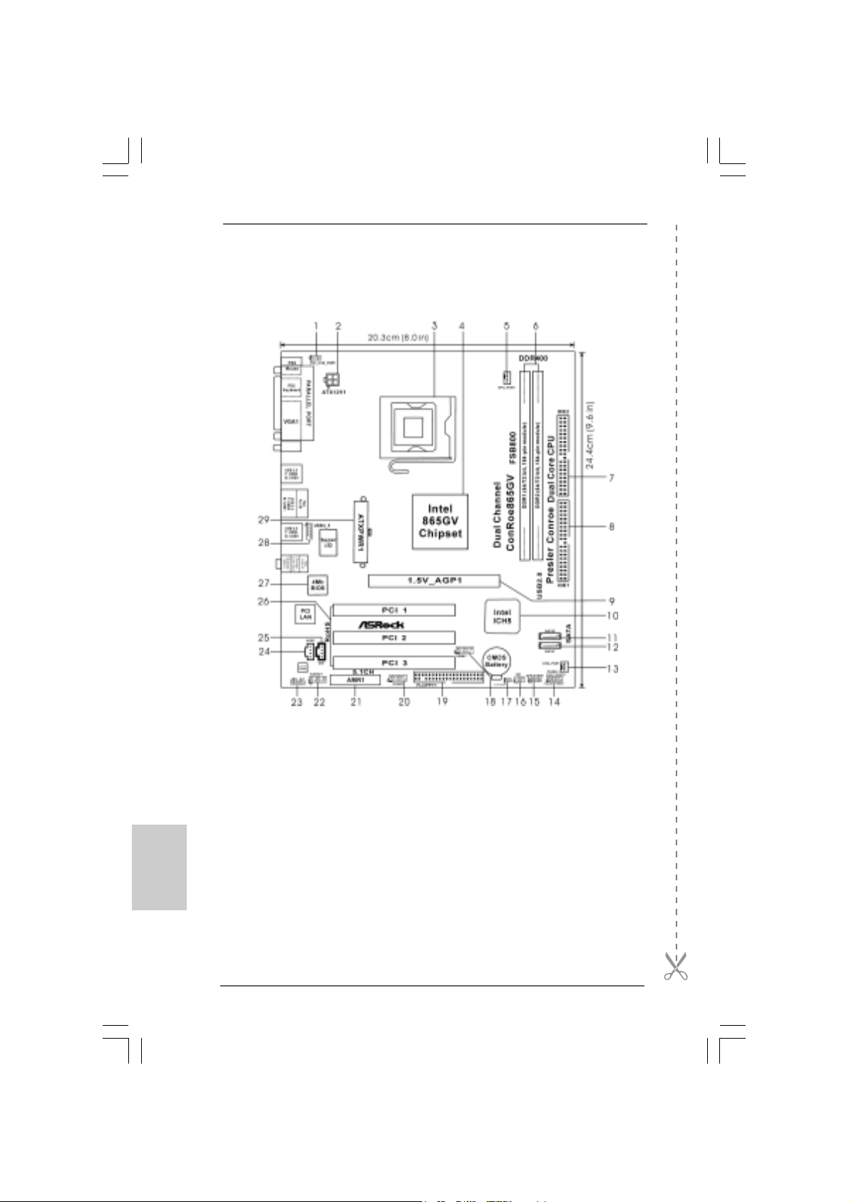
1 PS2_USB_PWR1 Jumper 16 Infrared Module Header (IR1)
2 A TX 12V Connector (A TX12V1) 17 Clear CMOS Jumper (CLRCMOS0)
3 775-Pin CPU Socket 18 USB 2.0 Header (USB67, Blue)
4 North Bridge Controller 19 Floppy Connector (FLOPPY1)
5 CPU Fan Connector (CPU_FAN1) 20 COM Port Header (COM1)
6 184-pin DDR DIMM Slots (DDR1- 2, Dual Channel) 21 AMR Slot (AMR1)
7 Secondary IDE Connector (IDE2, Black) 22 Front Panel Audio Header (AUDIO1)
8 Primary IDE Connector (IDE1, Blue) 23 JR1 Jumper / JL1 Jumper
9 ASRock Graphics Interface Slot (1.5V_AGP1) 24 Internal Audio Connector: AUX1 (White)
10 South Bridge Controller 25 Internal Audio Connector: CD1 (Black)
11 Secondary Serial A T A Conne ctor (SA T A2 ) 26 PCI Slots (PCI1- 3)
12 Primary Serial A T A Conne ctor (SA T A1 ) 27 BIOS FWH Chip
13 Chassis Fan Connector (CHA_FAN1) 28 Shared USB 2.0 Header (USB4_5, Blue)
14 System Panel Header (P ANEL1) 29 ATX 12V Connector (A TX12V1)
15 Chassis Speaker Header (SPEAKER 1)
ASRock ConRoe865GV Motherboard
Page 3
TMTM
TM
ASRock I/O PlusASRock I/O Plus
ASRock I/O Plus
ASRock I/O PlusASRock I/O Plus
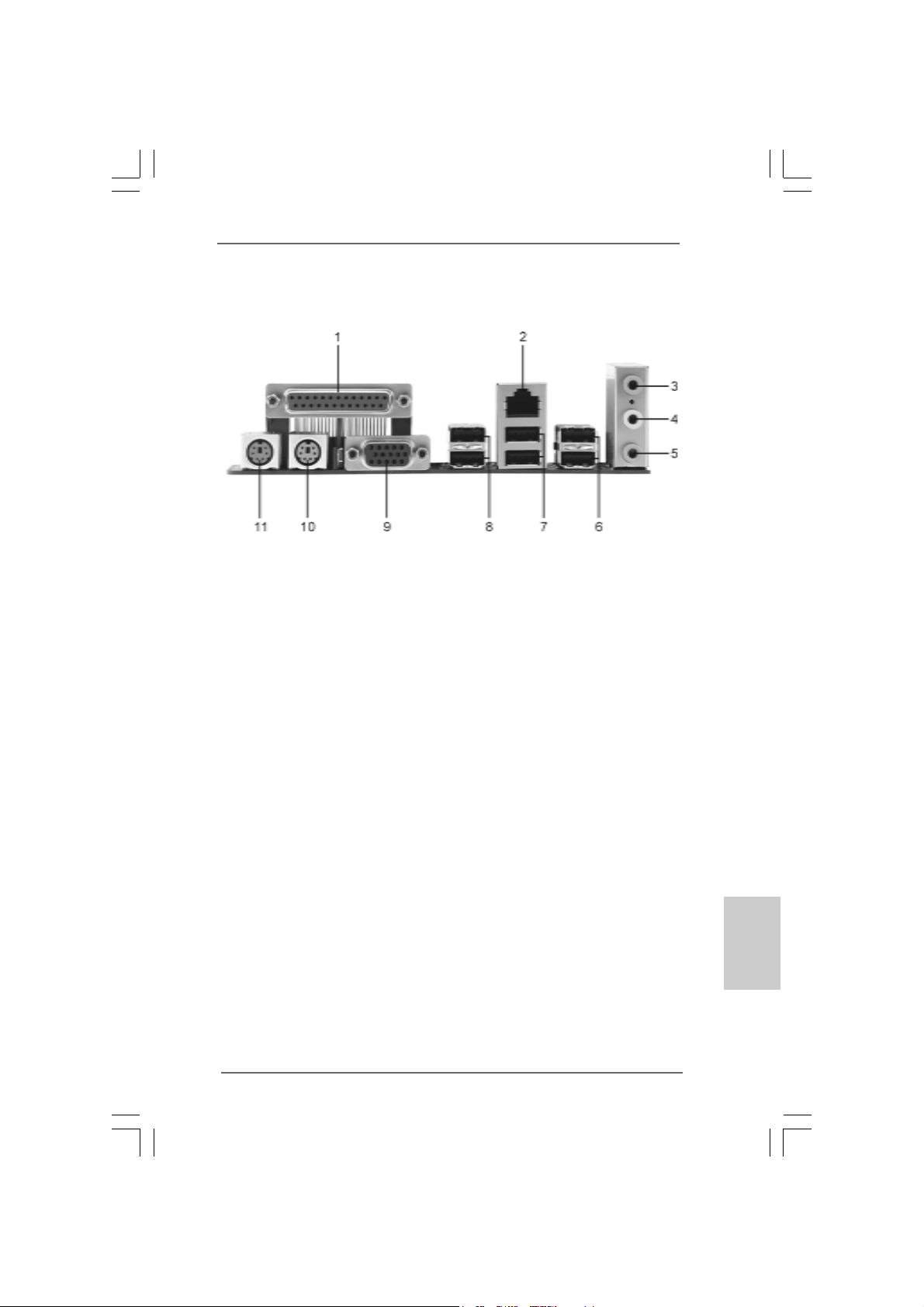
1 Parallel Port 7 USB 2.0 Ports (USB01)
2 RJ-45 Port 8 USB 2.0 Ports (USB23)
3 Line In (Light Blue) 9 VGA Port
4 Line Out (Lime) 10 PS/2 Keyboard Port (Purple)
5 Microphone (Pink) 11 PS/2 Mouse Port (Green)
6 Shared USB 2.0 Ports (USB45)
TMTM
ASRock ConRoe865GV Motherboard
EnglishEnglish
EnglishEnglish
English
33
3
33
Page 4
1. Introduction1. Introduction
1. Introduction
1. Introduction1. Introduction
Thank you for purchasing ASRock ConRoe865GV motherboard, a reliable
motherboard produced under ASRock’s consistently stringent quality control. It delivers excellent performance with robust design conforming to ASRock’s commitment to quality and endurance.
This Quick Installation Guide contains introduction of the motherboard and step-bystep installation guide. More detailed information of the motherboard can be found in
the user manual presented in the Support CD.
Because the motherboard specifications and the BIOS software might be
updated, the content of this manual will be subject to change without
notice. In case any modifications of this manual occur, the updated
version will be available on ASRock website without further notice. You
may find the latest VGA cards and CPU support lists on ASRock website
as well. ASRock website
1.1 Package Contents1.1 Package Contents
1.1 Package Contents
1.1 Package Contents1.1 Package Contents
ASRock ConRoe865GV Motherboard
(Micro ATX Form Factor: 9.6-in x 8.0-in, 24.4 cm x 20.3 cm)
ASRock ConRoe865GV Quick Installation Guide
ASRock ConRoe865GV Support CD
(including LGA 775 CPU Installation Live Demo)
One 80-conductor Ultra ATA 66/100 IDE Ribbon Ca ble
One Ribbon Cable for a 3.5-in Floppy Drive
One Serial ATA (SATA) Data Cable (Optional)
One Serial ATA (SATA) HDD Power Cable (Optional)
One ASRock I/O PlusTM Shield
One COM Port Bracket
One ASRock M R Card (Option al)
http://www.asrock.com
English
EnglishEnglish
EnglishEnglish
44
4
44
ASRock ConRoe865GV Motherboard
Page 5
1.21.2
SpecificationsSpecifications
1.2
Specifications
1.21.2
SpecificationsSpecifications
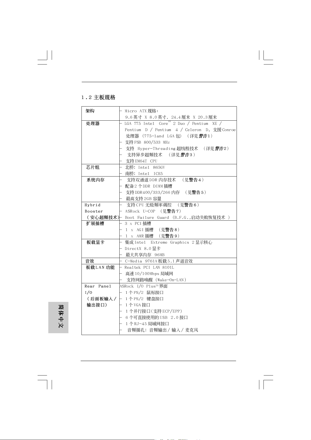
Platform - Micro ATX Form Factor: 9.6-in x 8.0-in, 24.4 cm x 20.3 cm
CPU - LGA 775 for Intel® CoreTM 2 Duo / Pentium® XE / Pentium® D /
Pentium® 4 / Celeron® D, supporting Conroe processors
(in 775-land LGA package) (see CAUTION 1)
- FSB 800/533 MHz
- Supports Hyper-Threading Technology (see CAUTION 2)
- Supports Untied Overclocking Technology (see CAUTION 3)
- Supports EM64T CPU
Chipset - Northbridge: Intel® 865GV
- Southbridge: Intel® ICH5
Memory - Dual Channel DDR memory technology (see CAUTION 4)
- 2 x DDR DIMM slots
- Support DDR400/333/266 (see CAUTION 5)
- Max. capacity: 2GB
Hybrid Booster - CPU Frequency Stepless Control (see CAUTION 6)
- ASRock U-COP (see CAUTION 7)
- Boot Failure Guard (B.F.G.)
Expansion Slot - 3 x PCI slots
- 1 x AGI slot (see CAUTION 8)
- 1 x AMR slot (see CAUTION 9)
Graphics - Integrated Intel® Extreme Graphics 2
- DirectX 8.0
- Max. shared memory 96MB
Audio - C-Media 9761A 5.1 channel audio CODEC
LAN - Realtek PCI LAN 8101L
- Speed: 10/100 Ethernet
- Supports Wake-On-LAN
Rear Panel I/O ASRock I/O Plus
- 1 x PS/2 Mouse Port
- 1 x PS/2 Keyboard Port
- 1 x VGA Port
- 1 x Parallel Port (ECP/EPP Support)
- 6 x Ready-to-Use USB 2.0 Ports
- 1 x RJ-45 LAN Port
- Audio Jack: Line in/Front Speaker/Microphone
TM
EnglishEnglish
EnglishEnglish
English
ASRock ConRoe865GV Motherboard
55
5
55
Page 6
English
EnglishEnglish
EnglishEnglish
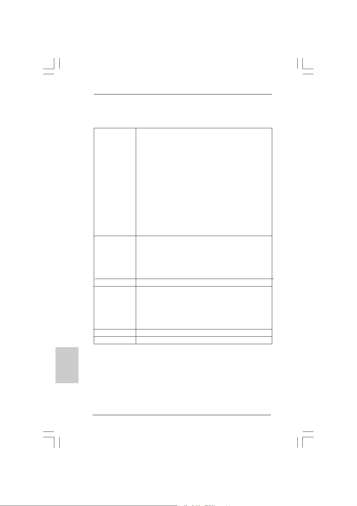
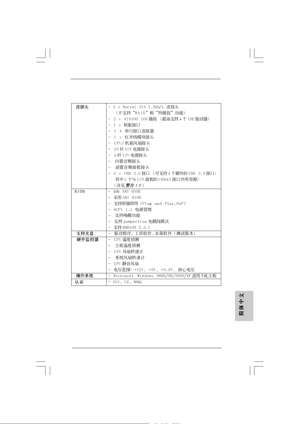
Connector - 2 x Serial ATA 1.5 Gb/s connectors
(No Support for RAID and “Hot Plug” functions)
- 2 x ATA100 IDE connectors (support 4 x IDE devices)
- 1 x Floppy connector
- 1 x COM port header
- 1 x IR header
- CPU/Chassis FAN connector
- 20 pin ATX power connector
- 4 pin 12V power connector
- CD in header
- AUX in header
- Front panel audio connector
- 2 x USB 2.0 headers (support 4 USB 2.0 ports; 2 of them are
shared with USB45 ports on the I/O panel)
(see CAUTION 10)
BIOS Feature - 4Mb AMI BIOS
- AMI Legal BIOS
- Supports “Plug and Play”
- ACPI 1.1 Compli ance Wake Up Events
- Supports jumperfree
- AMBIOS 2.3.1 Support
Support CD - Drivers, Utilities, AntiVirus Software (Trial Version)
Hardware - CPU Temperature Sensing
Monitor - Chassis Temperature Sensing
- CPU Fan Tachometer
- Chassis Fan Tachometer
- CPU Quiet Fan
- Voltage Monitoring: +12V, +5V, +3.3V, Vcore
OS - Microsoft® Windows® 98SE / ME / 2000 / XP compliant
Certifications - FCC, CE, WHQL
66
6
66
ASRock ConRoe865GV Motherboard
Page 7
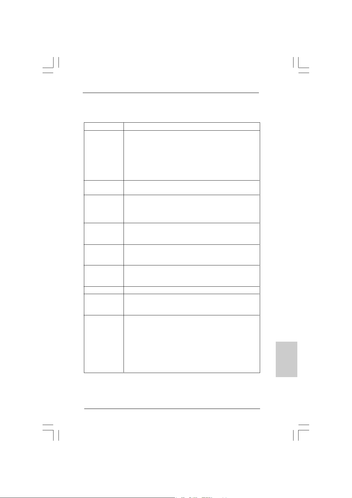
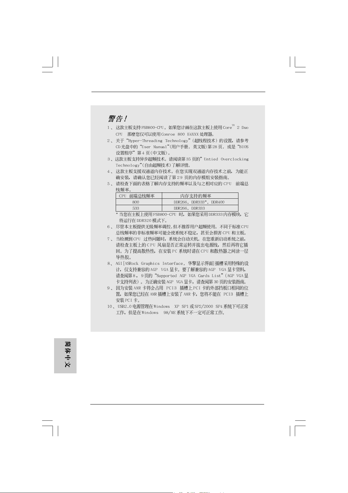
CAUTION!
1. This motherboard supports FSB800-CPU. If you plan to adopt CoreTM 2
Duo CPU on this motherboard, you can only adopt Conroe 800 E4XXX
processors.
2. About the setting of “Hyper Threading Technology”, please check page 28
of “User Manual” in the support CD.
3. This motherboard supports Untied Overclocking Technology. Plea se re ad “Untied Overclocking Technology” on page 19 for details.
4. This motherboard supports Dual Channel Memory Technology. Before you
implement Dual Channel Memory Technology, make sure to read the
installation guide of memory modules on page 13 for proper installation.
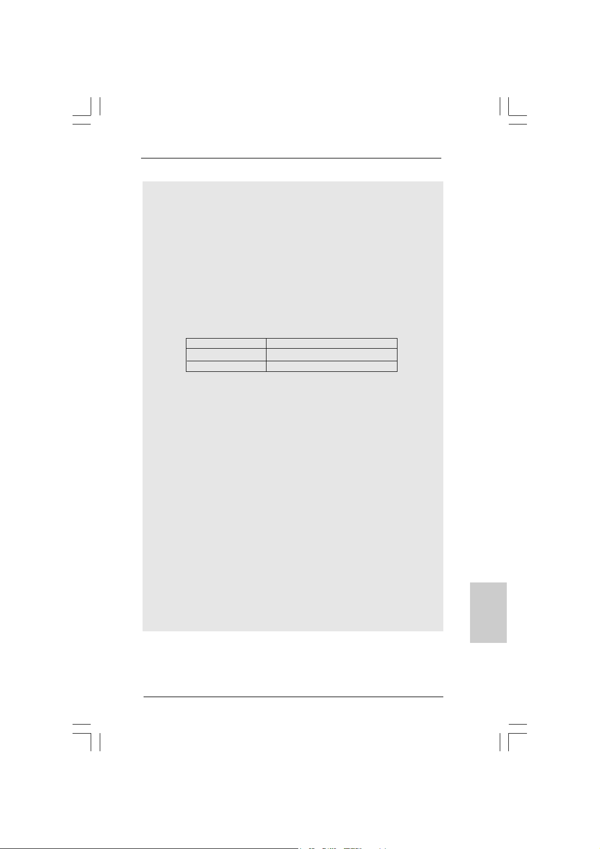
5. Please check the table below for the memory support frequency and its
corresponding CPU FSB frequency.
CPU FSB Frequency Memory Support Frequency
800 DDR266, DDR333
533 DDR266, DDR333
* When you use an FSB800-CPU on this motherboard, it will run at
DDR320 if you adopt a DDR333 memory module.
6. Although this motherboard offers stepless control, it is not recommended
to perform over-clocking. Frequencies other than the recommended CPU
bus frequencies may cause the instability of the system or damage the
CPU.
7. While CPU overheat is detected, the system will automatically shutdown.
Before you resume the system, please check if the CPU fan on the
motherboard functions properly and unplug the power cord, then plug it
back again. To improve heat dissipation, remember to spray thermal
grease between the CPU a nd the he atsink when you in stall the PC system.
8. The AGI [ASRock Graphics Interface] slot is a special design that only
supports compatible AGP VGA cards. For the information of the compatible
AGP VGA cards, please refer to the “Supported AGP VGA Cards List” on
page 8 and page 9. For the proper installation of AGP VGA card, please
refer to the installation guide on page 14.
9. Because the installed AMR card will occupy the same external connecting
position with the PCI card that are installed in “PCI3” slot, you will not be
able to install any PCI card in “PCI3” slot if an AMR card has already been
installed in the AMR slot.
10. Power Management for USB 2.0 works fine under Microsoft
XP SP1 or SP2 / 2000 SP4. It may not work properly under Microsoft
Windows® 98 / ME.
*, DDR400
®
Windows
®
®
EnglishEnglish
EnglishEnglish
English
ASRock ConRoe865GV Motherboard
77
7
77
Page 8
English
EnglishEnglish
EnglishEnglish
1.31.3
Supported AGP VGA Cards ListSupported AGP VGA Cards List
1.3
Supported AGP VGA Cards List
1.31.3
Supported AGP VGA Cards ListSupported AGP VGA Cards List
(for Windows® 2000/Windows® XP)
I. AGP 4X
Graphics Chip Model Name Chipset Name
Vendor
NVIDIA ASUS V8170 GeForce MX440SE
Ennyah G2 MX400 GeForce 2 MX400
II. AGP 8X
Graphics Chip Model Name Chipset Name
Vendor
NVIDIA ASUS N6200 NVIDIA GeForce 6200A
ASUS N6200GE/TD/128M NVIDIA GeForce 6200
ASUS N6600LE/TD/256M NVIDIA GeForce 6600 LE
ASUS V9180 Magic GF4 MX 440 64M
ASUS V9400MAGIC GeForce 4 MX4000
ASUS V9520-X/128M GeForce FX 5200
ASUS V9560/TD GeForce FX5600
ASUS V9570/TD/256M GeForce FX5700
ASUS V9950ULTRA GeForce FX 5900 Ultra
ASUS V9999 Ultra/2DT 6800 Ultra 256M
Albatron AGP6600GT 6600GT
Albatron FX5600P Turbo GeForce FX 5600
Albatron MX-480E GeForce 4 MX440-8X
Aopen Aeolus Fx5200-DV 128 FX 5200 128M
CHAINTECH SA5900X NVIDIA GeForce 5900XT
ELSA GLADIC FX733 NVIDIA GeForce 5500
Ennyah GeForce FX5200 ULTRA GeForce FX 5200 Ultra
Gigabyte GV -N57L256D GeForce FX 5700 LE
Gigabyte GV -N66128DP GeForce 6600
Inno3D GeForce FX 5600 128MB NVIDIA GeForce FX 5600
Leadtek WinFa st A340PRO/TD GeForce FX 5500
Leadtek WinFast A340TDH GeForce FX 5200
Leadtek WinFast A360TD GeForce FX 5600
Leadtek WinFast A400T DH GeForce 6800
Leadtek WinFast A6600 GT TDH GeForce 6600GT
MSI FX5700-TD128 GeForce FX 5700
MSI FX5700-VTD128 NVIDIA GeForce 5700
Prolink FX5900/128M FX5900
Prolink PV-N36AX FX 5700 LE 128MB
XFX 7800GS NVIDIA GeForce 7800GS
88
8
88
ASRock ConRoe865GV Motherboard
Page 9
AT I ASUS A9800XT ATI Radeon 9800 XT
ELSA FALCOX 920FX Radeon 9200
GECUBE Radeon 9250/128M Radeon 9250
MSI RX 9200 SE-T128 Radeon 9200 SE
PowerColor Radeon 9200SE Radeon 9200SE
PowerColor RADEON 9250/128M Radeon 9250
* ATI 9600/9550 series and all Matrox series VGA cards are NOT supported with AGI.
For the latest updates of the supported AGP VGA cards list, please visit
ASRock website for details.
ASRock website: http://www.asrock.com/support/index.htm
ASRock ConRoe865GV Motherboard
EnglishEnglish
EnglishEnglish
English
99
9
99
Page 10
2.2.
InstallationInstallation
2.
Installation
2.2.
InstallationInstallation
Pre-installation PrecautionsPre-installation Precautions
Pre-installation Precautions
Pre-installation PrecautionsPre-installation Precautions
Take note of the following precautions before you install motherboard components or change any motherboard settings.
1. Unplug the power cord from the wall socket before touching any
component. Failure to do so may cause severe damage to the
motherboard, peripherals, and/or components.
2. To avoid damaging the motherboard components due to static
electricity, NEVER place your motherboard directly on the carpet
or the like. Also remember to use a grounded wrist strap or touch
a safety grounded object before you handle components.
3. Hold components by the edges and do not touch the ICs.
4. Whenever you uninstall any component, place it on a grounded
antstatic pad or in the bag that comes with the component.
5. When placing screws into the screw holes to secure the
motherboard to the chassis, please do not over-tighten the
screws! Doing so may damage the motherboard.
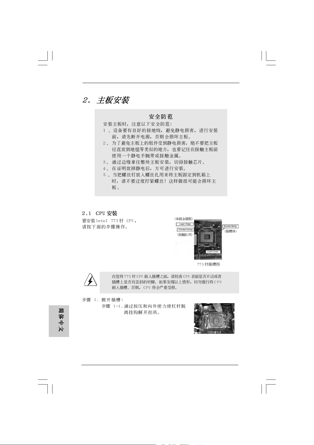
2.12.1
CPU InstallationCPU Installation
2.1
CPU Installation
2.12.1
CPU InstallationCPU Installation
For the installation of Intel 775-Pin CPU,
please follow the steps below.
English
EnglishEnglish
EnglishEnglish
1010
10
1010
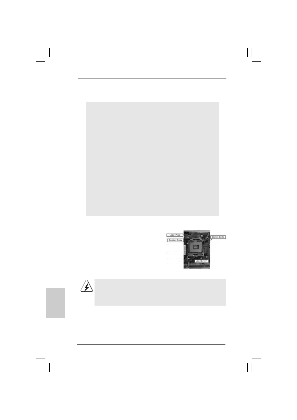
775-Pin Socket Overview
Before you insert the 775-Pin CPU into the socket, please check if the
CPU surface is unclean or if there is any bent pin on the socket. Do
not force to insert the CPU into the socket if above situation is found.
Otherwise, the CPU will be seriously damaged.
ASRock ConRoe865GV Motherboard
Page 11
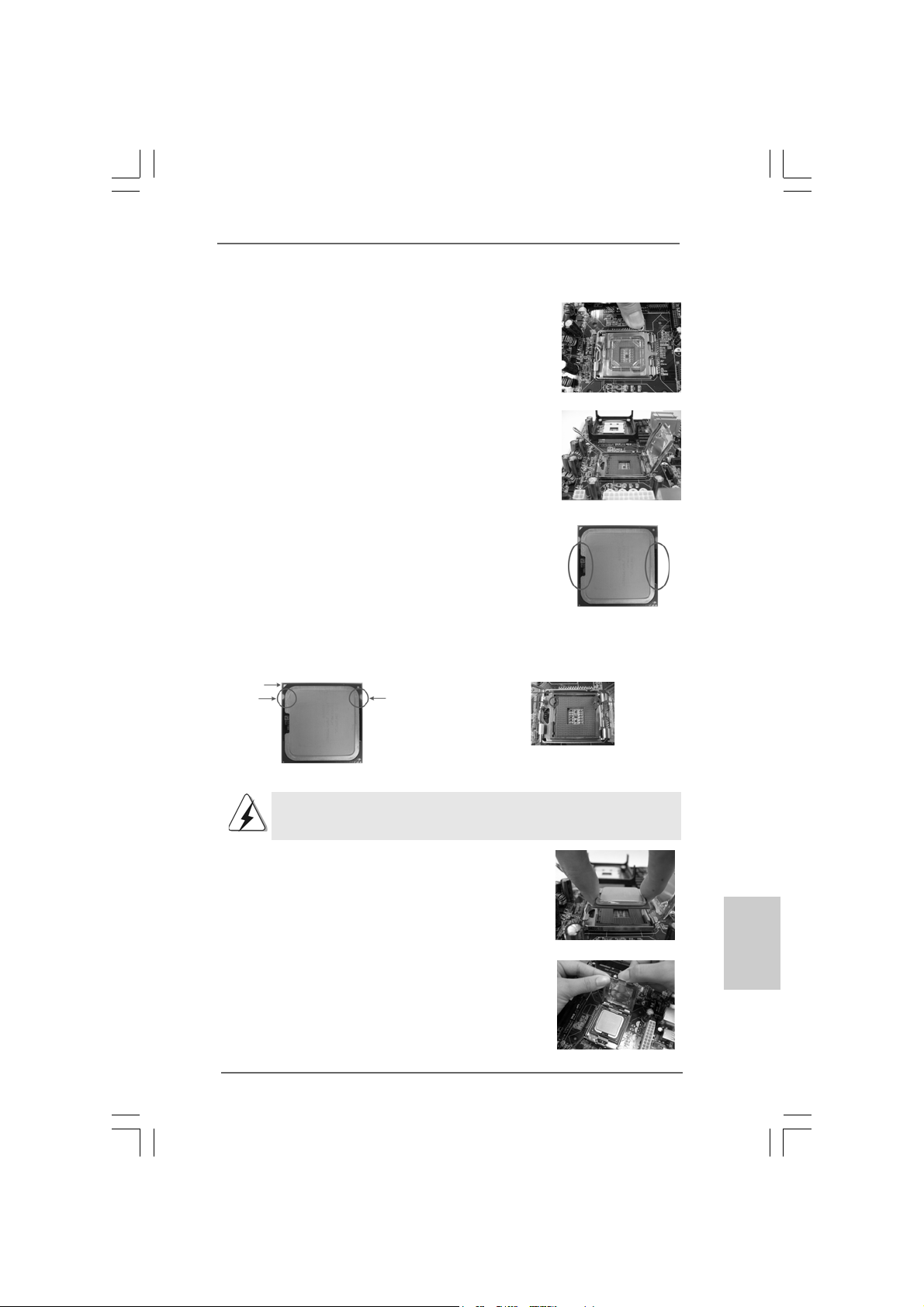
Step 1. Open the socket:
Step 1-1. Disengaging the lever by depressing
down and out on the hook to clear
retention tab.
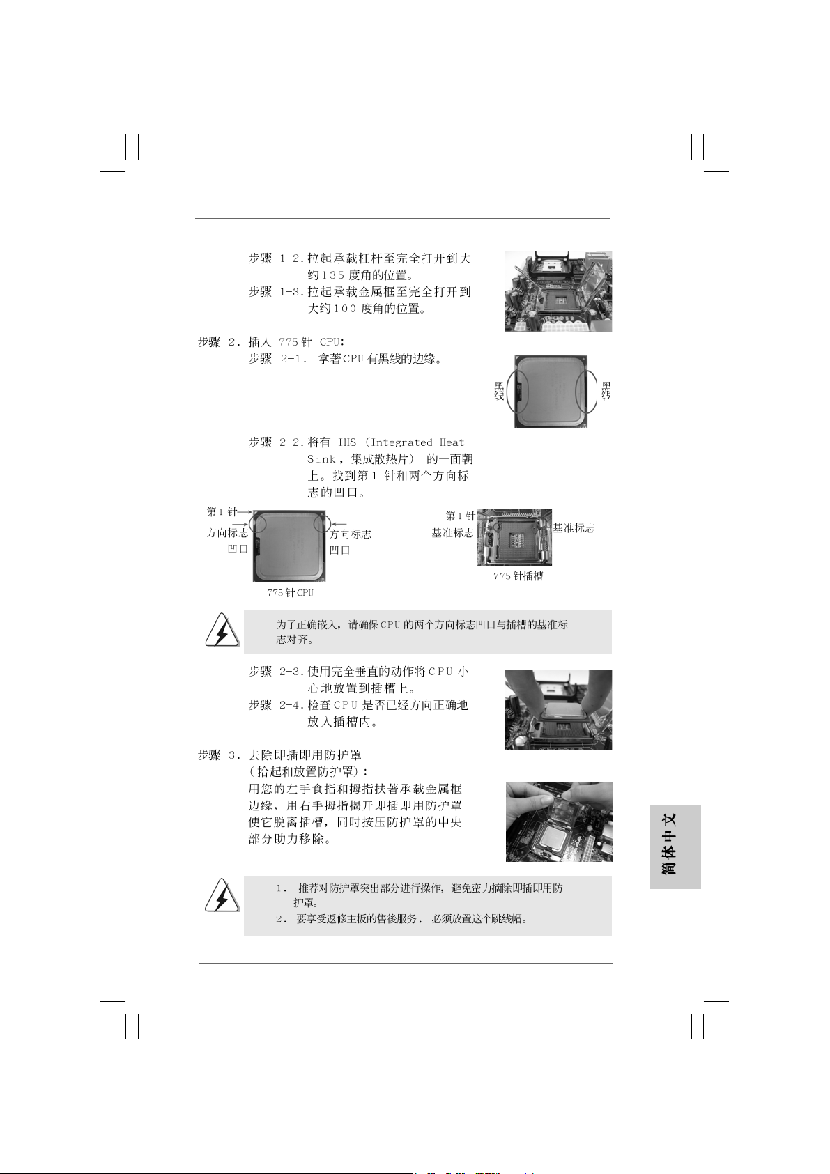
Step 1-2. Rotate the load lever to fully open po-
sition at approximately 135 degrees.
Step 1-3. Rotate the load plate to fully open po-
sition at approximately 100 degrees.
Step 2. Insert the 775-Pin CPU:
Step 2-1. Hold the CPU by the edges where are
marked with black lines.
Step 2-2. Orient the CPU with IHS (Integrated
Heat Sink) up. Locate Pin1 and the two
orientation key notches.
Pin1
orientation
key notch
orientation
key notch
Pin1
alignment key
black line
black line
alignment key
775-Pin CPU
For proper inserting, please ensure to match the two orientation key
notches of the CPU with the two alignment keys of the socket.
Step 2-3. Carefully place the CPU into the socket
by using a purely vertical motion.
Step 2-4. Verify that the CPU is within the socket
and properly mated to the orient keys.
Step 3. Remove PnP Cap (Pick and Place Cap):
Use your left hand index finger and thumb to
support the load plate edge, engage PnP cap
with right hand thumb and peel the cap from the
socket while pressing on center of PnP cap to
assist in removal.
ASRock ConRoe865GV Motherboard
775-Pin Socket
1111
11
1111
EnglishEnglish
EnglishEnglish
English
Page 12
English
EnglishEnglish
EnglishEnglish
1. It is recommended to use the cap tab to handle and avoid kicking
off the PnP cap.
2. This cap must be placed if returning the motherboard for after
service.
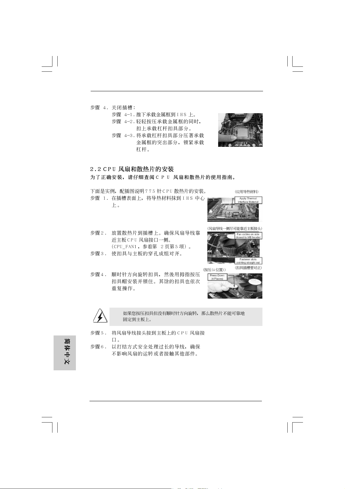
Step 4. Close the socket:
Step 4-1. Rotate the load plate onto the IHS.
Step 4-2. While pressing down lightly on load
plate, engage the load lever.
Step 4-3. Secure load lever with load plate tab
under retention tab of load lever.
2.22.2
Installation of CPU Fan and HeatsinkInstallation of CPU Fan and Heatsink
2.2
Installation of CPU Fan and Heatsink
2.22.2
Installation of CPU Fan and HeatsinkInstallation of CPU Fan and Heatsink
For proper installation, please kindly refer to the instruction manuals of
your CPU fan and heatsink.
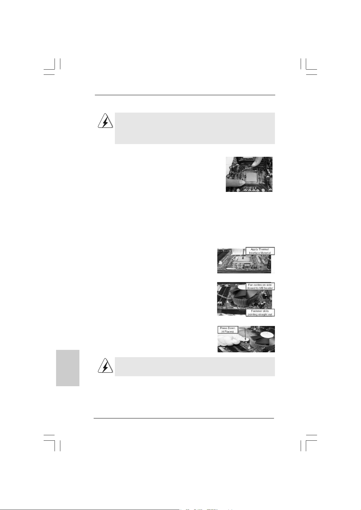
Below is an example to illustrate the installation of the heatsink for 775-Pin CPU.
Step 1. Apply thermal interface material onto center
of IHS on the socket surface.
Step 2. Place the heatsink onto the socket. Ensure
fan cables are oriented on side closest to the
CPU fan connector on the motherboard
(CPU_FAN1, see page 2, No. 5).
Step 3. Align fasteners with the motherboard
throughholes.
Step 4. Rotate the fastener clockwise, then press
down on fastener caps with thumb to install
and lock. Repeat with remaining fasteners.
If you press down the fasteners without rotating them clockwise,
the heatsink cannot be secured on the motherboard.
Step 5. Connect fan header with the CPU fan
connector on the motherboard.
Step 6. Secure excess cable with tie-wrap to ensure
cable does not interfere with fan operation or
1212
12
1212
contact other components.
ASRock ConRoe865GV Motherboard
Page 13
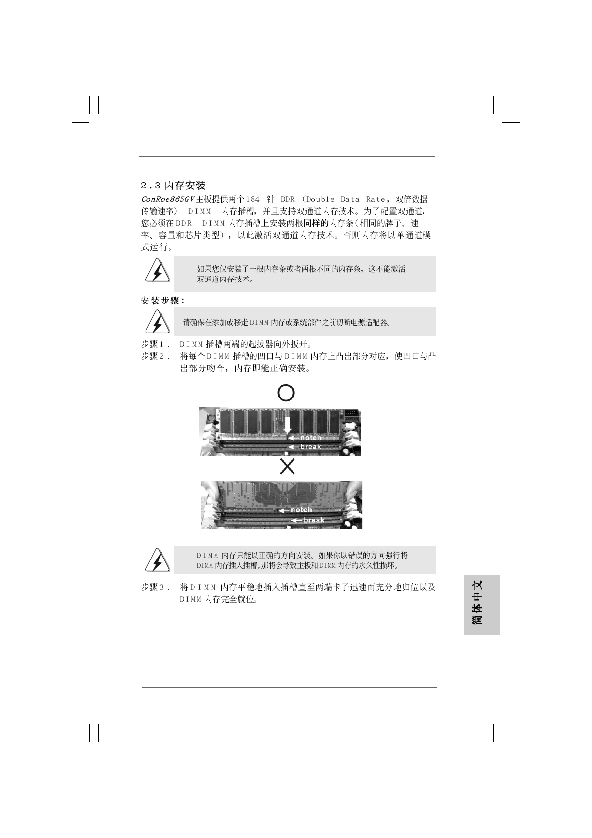
2.3 Installation of Memory Modules (DIMM)2.3 Installation of Memory Modules (DIMM)
2.3 Installation of Memory Modules (DIMM)
2.3 Installation of Memory Modules (DIMM)2.3 Installation of Memory Modules (DIMM)
ConRoe865GV motherboard provides two 184-pin DDR (Double Data Rate) DIMM
slots, and supports Dual Cha nnel Me mory Technology. For dual channel configuration,
you always need to install two identical (the same brand, speed, size and chiptype) memory modules in the DDR DIMM slots to activate Dual Channel Memory
Technology. Otherwise, it will operate at single channel mode.
If you install only one memory module or two non-identical memory
modules, it is unable to activate the Dual Channel Memory Technology .
Installing a DIMMInstalling a DIMM
Installing a DIMM
Installing a DIMMInstalling a DIMM
Please make sure to disconnect power supply before adding or
removing DIMMs or the system components.
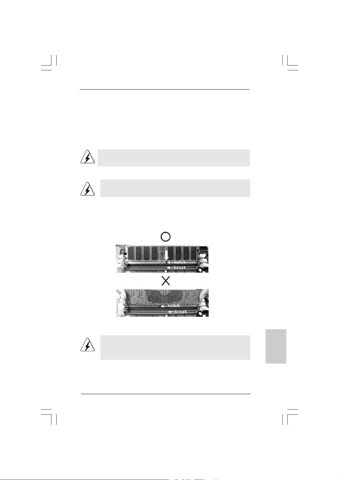
Step 1. Unlock a DIMM slot by pressing the retaining clips outward.
Step 2. Align a DIMM on the slot such that the notch on the DIMM matches the bre a k
on the slot.
The DIMM only fits in one correct orientation. It will cause permanent
damage to the motherboard and the DIMM if you force the DIMM into the
slot at incorrect orientation.
Step 3. Firmly insert the DIMM into the slot until the retaining clips at both ends fully
snap back in place and the DIMM is properly seated.
ASRock ConRoe865GV Motherboard
1313
13
1313
EnglishEnglish
EnglishEnglish
English
Page 14
2.4 Expansion Slots (PCI, AMR, and AGI Slots)2.4 Expansion Slots (PCI, AMR, and AGI Slots)
2.4 Expansion Slots (PCI, AMR, and AGI Slots)
2.4 Expansion Slots (PCI, AMR, and AGI Slots)2.4 Expansion Slots (PCI, AMR, and AGI Slots)
There are 3 PCI slots, 1 AMR slot, and 1 AGI slot on this motherboard.
PCI slots: PCI slots are used to install expansion cards that have the 32-bit PCI
interface.
Because the installed AMR card will occupy the same external
connecting position with the PCI card installed in “PCI3” slot, you will
no be able to install any PCI card in “PCI3” slot if an AMR card has
already been installed in the AMR slot.
AMR slot: AMR slot is used to insert an ASRock MR card (optional) with v.92
Modem functionality.
AGI slot: The AGI [ASRock Graphics Interface] slot is a special design that only
supports compatible AGP VGA cards. For the information of the compatible AGP VGA cards, plea se refer to the “Supported AGP V GA Cards List”
on page 8 and page 9.
To install the system with an add-on AGP VGA card, you must make
sure to install the driver of add-on AGP VGA card before you install
the onboard VGA driver. If the onboard VGA driver has already been
installed before you install the add-on AGP VGA card, the system will
automatically set the onboard V GA as the primary gra phics a d apter. In
that case, if you want to install the add-on AGP VGA card, you need
to remove the onboard VGA driver first, and then install the add-on
AGP VGA card and its driver. For the detailed instruction, please refer
to the documents in the Support CD, “AGI Slot Installation Guide (for
Windows 2000)” and “AGI Slot Installation Guide (for Windows XP)”,
which are located in the folder at the following path:
..\ Easy Dual Monitor
English
EnglishEnglish
EnglishEnglish
1414
14
1414
Installing an expansion cardInstalling an expansion card
Installing an expansion card
Installing an expansion cardInstalling an expansion card
Step 1. Before installing the expansion card, please make sure that the power
supply is switched off or the power cord is unplugged. Please read the
documentation of the expansion card and make necessary hardware
settings for the card before you start the installation.
Step 2. Remove the system unit cover (if your motherboard is already installed in a
chassis).
Step 3. Remove the bracket facing the slot that you intend to use. Keep the screws
for later use.
Step 4. Align the card connector with the slot and press firmly until the card is
completely seated on the slot.
Step 5. Fasten the card to the chassis with screws.
Step 6. Replace the system cover.
ASRock ConRoe865GV Motherboard
Page 15
2.5 Easy Dual Monitor Feature2.5 Easy Dual Monitor Feature
2.5 Easy Dual Monitor Feature
2.5 Easy Dual Monitor Feature2.5 Easy Dual Monitor Feature
Thanks to ASRock patented AGI8X Technology, this motherboard supports Easy
Dual Monitor upgrade. With the internal onboard VGA and the external add-on AGP
VGA card, you can easily enjoy the benefits of Dual Monitor feature. For the
detailed instruction, please refer to the document at the following path in the
Support CD: ..\ Easy Dual Monitor
2.6 Jumpers Setup2.6 Jumpers Setup
2.6 Jumpers Setup
2.6 Jumpers Setup2.6 Jumpers Setup
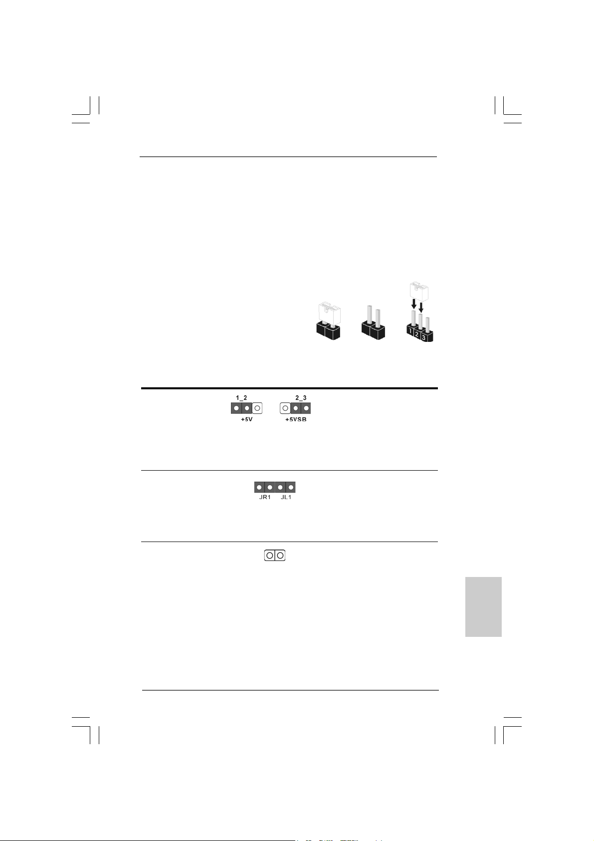
The illustration shows how jumpers are
setup. When the jumper cap is placed on
pins, the jumper is “Short”. If no jumper cap
is placed on pins, the jumper is “Open”. The
illustration shows a 3-pin jumper whose pin1
and pin2 are “Short” when jumper cap is
placed on these 2 pins.
Jumper Setting Description
PS2_USB_PWR1 Short pin2, pin3 to enable
(see p.2 No. 1) +5VSB (standby) for PS/2
Note:To select +5VSB, it requires 2 Amp and higher standby current provided by
power supply.
Short Open
or USB wake up events.
JR1 / JL1 Jumpers
(see p.2 No. 23)
Note:If JR1 and JL1 Jumpers are short, both the front panel and the rear panel
audio connectors can work.
Clear CMOS
(CLRCMOS0)
(see p.2 No. 17)
Note: CLRCMOS0 allows you to clear the data in CMOS. The data in CMOS includes
system setup information such as system password, date, time, and system
setup parameters. To clear and reset the system parameters to default setup,
please turn off the computer and unplug the power cord from the power
supply. After waiting for 15 seconds, use a jumper cap to short 2 pins on
CLRCMOS0 for 5 seconds.
ASRock ConRoe865GV Motherboard
2-pin jumper
1515
15
1515
EnglishEnglish
EnglishEnglish
English
Page 16
2.7 Onboard Headers and Connectors2.7 Onboard Headers and Connectors
2.7 Onboard Headers and Connectors
2.7 Onboard Headers and Connectors2.7 Onboard Headers and Connectors
Onboard headers and connectors are NOT jumpers. Do NOT place
jumper caps over these headers and connectors. Placing jumper caps
over the headers and connectors will cause permanent damage of the
motherboard!
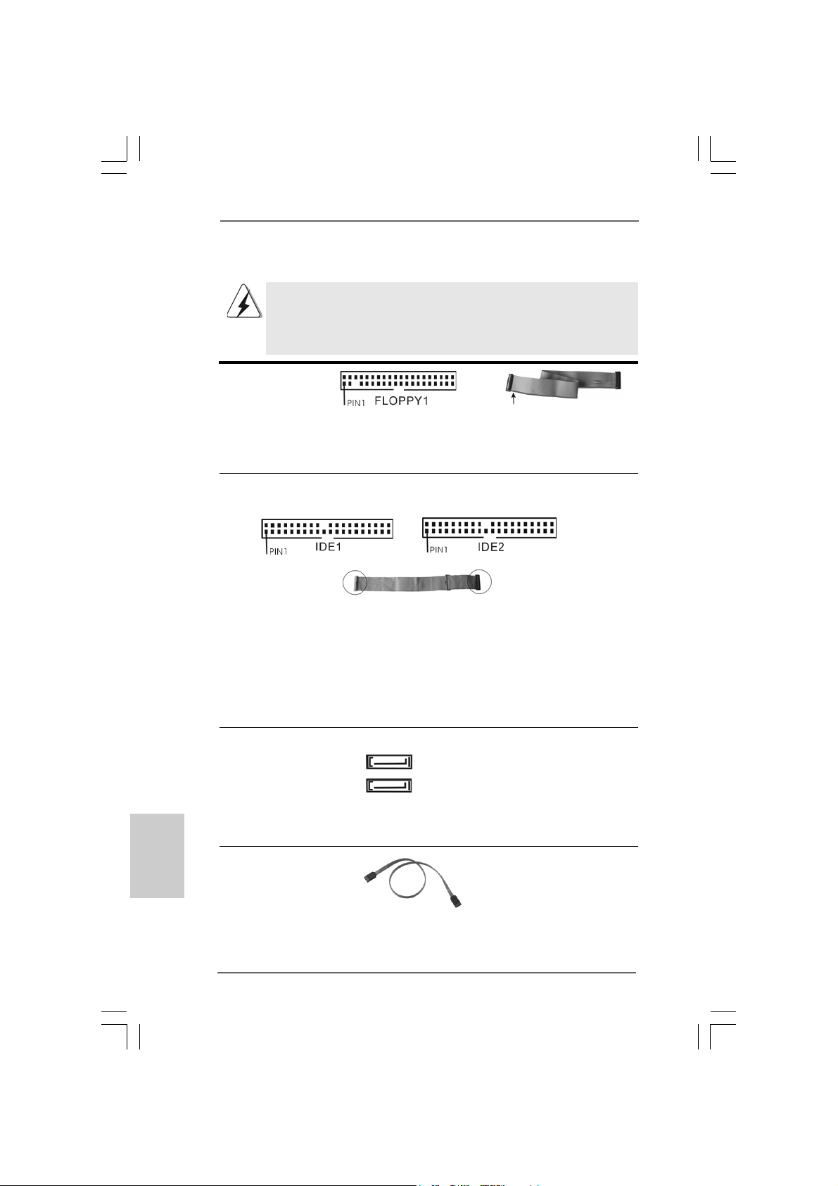
FDD connector
(33-pin FLOPPY1)
(see p.2 No. 19)
the red-striped side to Pin1
Note: Make sure the red-striped side of the cable is plugged into Pin1 side of the
connector.
Primary IDE connector (Blue) Secondary IDE connector (Black)
(39-pin IDE1, see p.2 No. 8) (39-pin IDE2, see p.2 No. 7)
English
EnglishEnglish
EnglishEnglish
1616
16
1616
connect the blue end
to the motherboard
connect the black end
to the IDE devices
80-Conductor ATA 66/100 cable
Note: If you use only one IDE device on this motherboard, please set the IDE
device as “Master”. Please refer to the instruction of your IDE device vendor
for the details. Besides, to optimize compatibility and performance, please
connect your hard disk drive to the primary IDE connector (IDE1, blue) and
CD-ROM to the secondary IDE connector (IDE2, black).
Serial ATA Connectors These two Serial ATA (SATA)
(SAT A1: see p.2 No. 12) connectors support SATA data
(SAT A2: see p.2 No. 1 1) cables for internal storage
SAT A2
SAT A1
devices. The current SATA
interface allows up to 1.5 Gb/s
data transfer rate.
Serial A TA (SATA) Either end of the SATA data cable
Data Cable can be connected to the SATA
(Optional) hard disk or the SA TA connector
on the motherboard.
ASRock ConRoe865GV Motherboard
Page 17
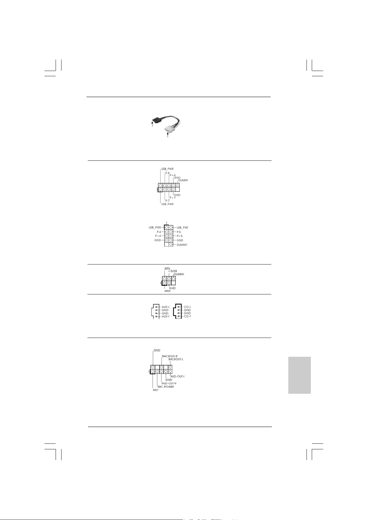
Serial ATA (SATA) Please connect the black end of
Power Cable SATA power cable to the power
(Optional) connector on each drive. Then
connect to the SAT A
HDD power connector
connect to the
power supply
connect the white end of SATA
power cable to the power
connector of the power supply.
USB 2.0 Header Besides six default USB 2.0
(9-pin USB67) ports on the I/O panel, there are
(see p.2 No. 18) two USB 2.0 headers on this
motherboard. Each USB 2.0
header cansupport two USB
2.0 ports. The shared USB 2.0
header (USB4_5) is shared with
Shared USB 2.0 Header USB ports 45 on the I/O panel.
(9-pin USB4_5) When using the front panel USB
(see p.2 No. 28) ports by attaching the front pa nel
USB cable to USB4_5 header,
the USB ports 45 on the I/O panel
will not be able to function.
Infrared Module Header This header supports an
(5-pin IR1) optional wireless transmitting
(see p.2 No. 16) and receiving infrared module.
Internal Audio Connectors These connectors allow you
(4-pin CD1, 4-pin AUX1) to receive stereo audio input
(CD1: see p.2 No. 25) from sound sources such as
(AUX1: see p.2 No. 24) a CD-ROM, D VD-ROM, TV
AUX1
CD1
tuner card, or MPEG card.
Front Panel Audio Header This is an interface for front
(8-pin AUDIO1) panel audio cable that allows
(see p.2 No. 22) convenient connection and
control of audio devices.
ASRock ConRoe865GV Motherboard
1717
17
1717
EnglishEnglish
EnglishEnglish
English
Page 18
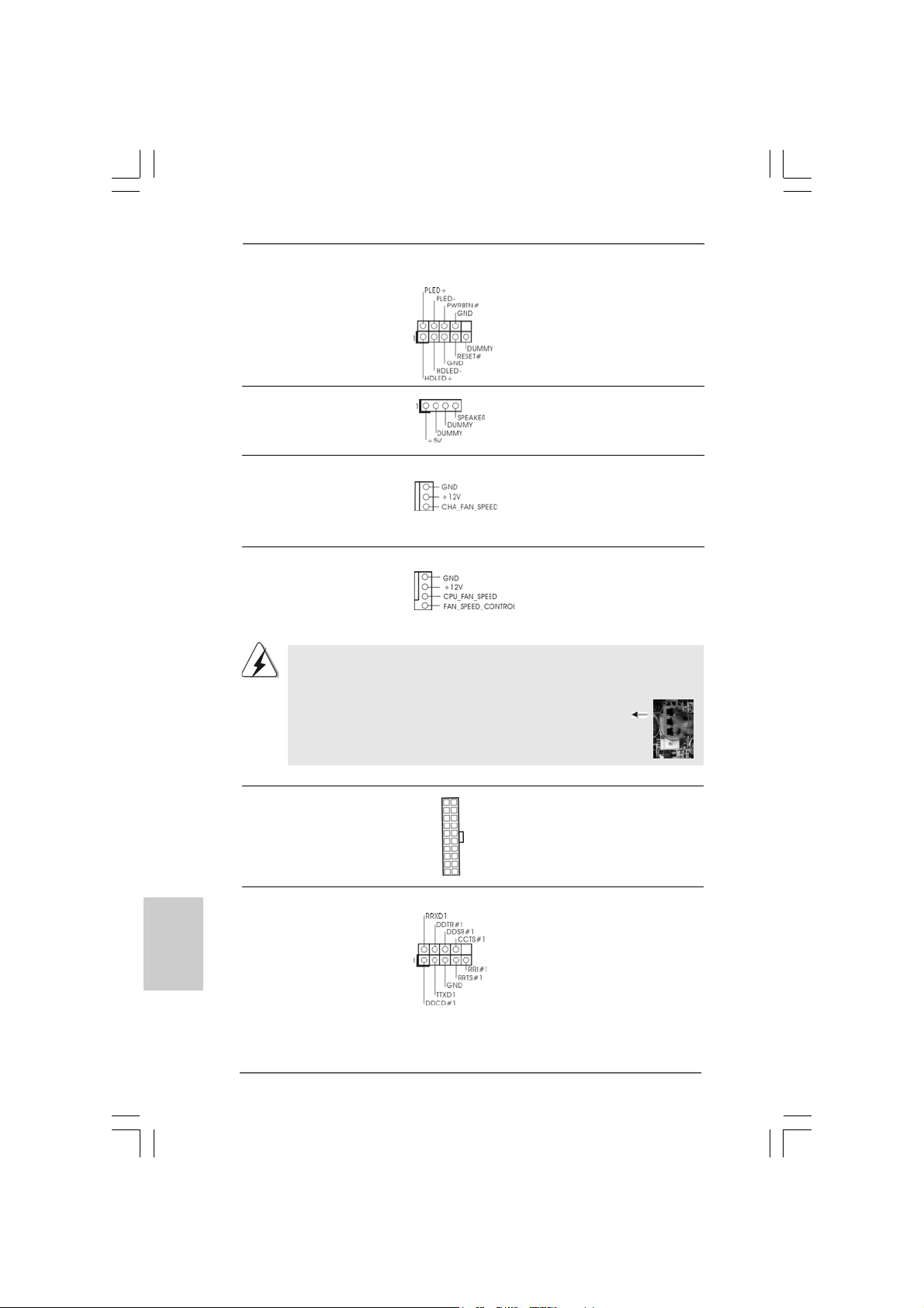
System Panel Header This header accommodates
(9-pin PANEL1) several system front panel
(see p.2 No. 14) functions.
Chassis Speaker Header Please connect the chassis
(4-pin SPEAKER 1) speaker to this header.
(see p.2 No. 15)
Chassis Fan Connector Please connect a chassis fan
(3-pin CHA_FAN1) cable to this connector and
(see p.2 No. 13) match the black wire to the
ground pin.
English
EnglishEnglish
EnglishEnglish
CPU Fan Connector You may connect either a 3-pin
(4-pin CPU_FAN1) or a 4-pin CPU fan cable to this
(see p.2 No. 5) connector, then match the black
1
2
3
4
wire to the ground pin.
Though this motherboard provides 4-Pin CPU fan (Quiet Fan) support, the 3-Pin
CPU fan still can work successfully even without the fan speed control function.
If you plan to connect the 3-Pin CPU fan to the CPU fan connector on this
motherboard, please connect it to Pin 1-3.
Pin 1-3 Connected
3-Pin Fan Installation
ATX Power Connector Please connect an ATX power
(20-pin ATXPW R1) supply to this connector.
(see p.2 No. 29)
COM Port Header This COM port header is used
(9-pin COM1) to support a COM port module.
(see p.2 No. 20)
1818
18
1818
ASRock ConRoe865GV Motherboard
Page 19
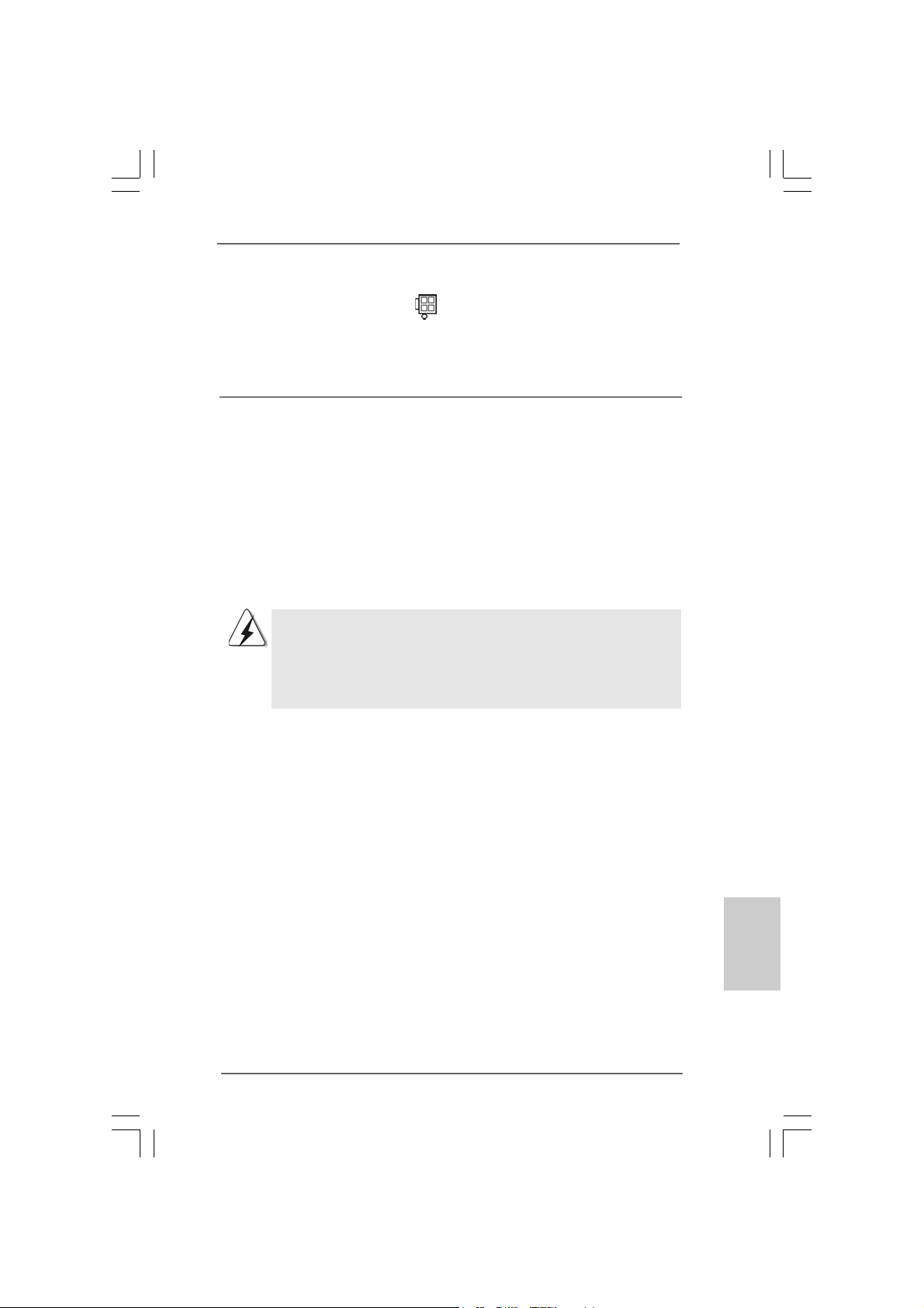
ATX 12V Connector Please note that it is necessary
(4-pin A TX12V1) to connect a power supply with
(see p.2 No. 2) ATX 12V plug to this connector
so that it can provides sufficient
power. Failing to do so will cause
the failure to power up.
2.82.8
Serial ASerial A
2.8
Serial A
2.82.8
Serial ASerial A
This motherboard adopts Intel® ICH5 south bridge chipset that supports Serial ATA
(SATA) hard disks. You may install SATA hard disks on this motherboard for
internal storage devices. This section will guide you to install the SATA hard disks.
STEP 1: Install the SATA hard disks into the drive bays of your chassis.
STEP 2: Connect the SATA power cable to the SATA hard disk.
STEP 3: Connect one end of the SATA data cable to the motherboard’s SATA
connector.
STEP 4: Connect the other end of the SATA data cable to the SATA hard disk.
TT
A (SAA (SA
TT
T
TT
Before you install OS into the SATA hard disk, you need to check and
ensure the configuration of the OnBoard IDE Operate Mode option in
BIOS setup is correct according to the condition of your system. For
the configuration details, please refer to the instruction on page 31 of
“User Manual” in the support CD.
A) Hard Disks InstallationA) Hard Disks Installation
A (SA
T
A) Hard Disks Installation
A (SAA (SA
TT
A) Hard Disks InstallationA) Hard Disks Installation
2.92.9
Driver Installation GuideDriver Installation Guide
2.9
Driver Installation Guide
2.92.9
Driver Installation GuideDriver Installation Guide
To install the drivers to your system, please insert the support CD to your optical
drive first. Then, the drivers compatible to your system can be auto-detected and
listed on the support CD driver page. Please follow the order from up to bottom
side to install those required drivers. Therefore, the drivers you install can work
properly.
2.102.10
Untied Overclocking TUntied Overclocking T
2.10
Untied Overclocking T
2.102.10
Untied Overclocking TUntied Overclocking T
This motherboard supports Untied Overclocking Technology, which means during
overclocking, FSB enjoys better margin due to fixed PCI bus. You may set “CPU Host
Frequency” option of BIOS setup to [Auto], which will show you the actual CPU host
frequency in the following item. Therefore, CPU FSB is untied during overclocking,
but PCI bus is in the fixed mode so that FSB can operate under a more stable
overclocking environment.
ASRock ConRoe865GV Motherboard
echnologyechnology
echnology
echnologyechnology
1919
19
1919
EnglishEnglish
EnglishEnglish
English
Page 20

3. BIOS Information3. BIOS Information
3. BIOS Information
3. BIOS Information3. BIOS Information
The BIOS Setup Utility is stored in the BIOS FWH chip. When you start up the
computer, please press <F2> during the Power-On-Self-Test (POST) to enter the
BIOS Setup Utility; otherwise, POST continues with its test routines. If you wish to
enter the BIOS Setup Utility after POST, please resume the system by pressing <Ctl>
+ <Alt> + <Delete>, or pressing the reset button on the system chassis. For the
detailed information about the BIOS Setup Utility, please refer to the User Manual
(PDF file) contained in the Support CD.
English
EnglishEnglish
EnglishEnglish
4. Software Suppor4. Software Suppor
4. Software Suppor
4. Software Suppor4. Software Suppor
This motherboard supports various Microsoft® Windows® operating systems: 98 SE/
ME / 2000 / XP. The Support CD that came with the motherboard contains necessary
drivers and useful utilities that will enhance motherboard features.
To begin using the Support CD, insert the CD into your CD-ROM drive. It will display
the Main Menu automatically if “AUTORUN” is enabled in your computer. If the Main
Menu does not appear automatically, locate and double-click on the file
“ASSETUP.EXE” from the “BIN” folder in the Support CD to display the menus.
“LGA 775 CPU Installation Live Demo”
This motherboard is equipped with Intel LGA 775 socket, which is a new CPU
socket interface that Intel has released. Since it has several tiny pins, whcih
are easily to be damaged by improper handling, ASRock sincerely presents
you a clear installation guide through this “LGA 775 CPU Installation Live
Demo”. We hope you may check this live demo program before you start the
installation of LGA 775 CPU in order to reduce the risks of CPU and
motherboard damages caused by any improper handling. To see this Live
Demo, you can run Microsoft® Media Player® to play the file. You may find this
Live Demo in the motherboard’s Support CD through the following path:
..\ Live Demo \ LGA 775 CPU Installation \ LGA775INST_English.DAT
t CD informationt CD information
t CD information
t CD informationt CD information
2020
20
2020
ASRock ConRoe865GV Motherboard
Page 21
ASRock ConRoe865GV Motherboard
2121
21
2121
Page 22
® ®
® ® ®
®
®
®
2222
22
2222
ASRock ConRoe865GV Motherboard
Page 23
®
®
ASRock ConRoe865GV Motherboard
2323
23
2323
Page 24
,
“ ”
“ ”
2424
24
2424
®
®
ASRock ConRoe865GV Motherboard
Page 25
® ®
ASRock ConRoe865GV Motherboard
2525
25
2525
Page 26
2626
26
2626
ASRock ConRoe865GV Motherboard
Page 27
ASRock ConRoe865GV Motherboard
2727
27
2727
Page 28
2828
28
2828
ASRock ConRoe865GV Motherboard
Page 29
ASRock ConRoe865GV Motherboard
2929
29
2929
Page 30
“ ”
“ ”
“
”
3030
30
3030
ASRock ConRoe865GV Motherboard
Page 31

ASRock ConRoe865GV Motherboard
3131
31
3131
Page 32

3232
32
3232
“ ”
SAT A2
SAT A1
ASRock ConRoe865GV Motherboard
Page 33

AUX1
ASRock ConRoe865GV Motherboard
CD1
3333
33
3333
Page 34

1
2
3
4
3434
34
3434
ASRock ConRoe865GV Motherboard
Page 35

ASRock ConRoe865GV Motherboard
3535
35
3535
Page 36

®
®
“LGA 775 CPU Installation Live Demo”
..\ Live Demo \ LGA 775 CPU Installation \ LGA775INST_SChinese.DAT
3636
36
3636
ASRock ConRoe865GV Motherboard
Page 37

1. Einführung1. Einführung
1. Einführung
1. Einführung1. Einführung
Wir danken Ihnen für den Kauf des ASRock ConRoe865GV Motherboard, ein
zuverlässiges Produkt, welches unter den ständigen, strengen Qualitätskontrollen
von ASRock gefertigt wurde. Es bietet Ihnen exzellente Leistung und robuste s Design,
gemäß der Verpflichtung von ASRock zu Qualität und Halbarkeit.
Diese Schnellinstallationsanleitung führt in das Motherboard und die schrittweise
Installation ein. Details über das Motherboard finden Sie in der
Bedienungsanleitung auf der Support-CD.
Da sich Motherboard-Spezifikationen und BIOS-Software verändern können,
kann der Inhalt dieses Handbuches ebenfalls jederzeit geändert werden. Für
den Fall, dass sich Änderungen an diesem Handbuch ergeben, wird eine neue
Version auf der ASRock-Website, ohne weitere Ankündigung, verfügbar sein.
Die neuesten Grafikkarten und unterstützten CPUs sind auch auf der
ASRock-Website aufgelistet.
ASRock-Website: http://www.asrock.com
1.1 Kartoninhalt
ASRock ConRoe865GV Motherboard
(Micro ATX-Formfaktor: 24.4 cm x 20.3 cm; 9.6 Zoll x 8.0 Zoll)
ASRock ConRoe865GV Schnellinstallationsanleitung
ASRock ConRoe865GV Support-CD
(einschl. LGA 775 CPU Installation Live-Demo)
Ein 80-adriges Ultra-ATA 66/100 IDE-Flachbandkabel
Ein Flachbandkabel für ein 3,5-Zoll-Diskettenlaufwerk
Ein Seriell-ATA- (SATA) Datenkabel (Option)
Ein Seriell-ATA (SATA) Festplattennetzkabel (Option)
Ein ASRock I/O Plus
Ein COM Port-Anschlusshalter
Ein ASRock MR-Karte (Option)
TM
Shield
ASRock ConRoe865GV Motherboard
3737
37
3737
DeutschDeutsch
DeutschDeutsch
Deutsch
Page 38

Deutsch
DeutschDeutsch
DeutschDeutsch
1.21.2
SpezifikationenSpezifikationen
1.2
Spezifikationen
1.21.2
SpezifikationenSpezifikationen
Plattform - Micro ATX-Formfaktor: 24.4 cm x 20.3 cm; 9.6 Zoll x 8.0 Zoll
CPU - LGA 775 für Intel® CoreTM 2 Duo- / Pentium® XE- / Pentium® D-
/ Pentium® 4- / Celeron® D-Prozessoren, Conroe- Prozessoren
(im 775-poligen LGA-Gehäuse) werden unterstützt
(siehe VORSICHT 1)
- FSB 800/533 MHz
- Unterstützt Hyper-Threading-Technologie
(siehe VORSICHT 2)
- Unterstützt Untied-Übertaktungstechnologie
(siehe VORSICHT 3)
- Unterstützt EM64T -CPU
Chipsatz - Northbridge: Intel® 865GV
- Southbridge: Intel® ICH5
Speicher - Unterstützung von Dual-Kanal-DDR-Speichertechnologie
(siehe VORSICHT 4)
- 2 x Steckplätze für DDR
- Unterstützt DDR400/333/266 (siehe VORSICHT 5)
- Max. 2GB
Hybrid Booster - Schrittloser CPU-Frequenz-Kontrolle (siehe VORSICHT 6)
- ASRock U-COP (siehe VORSICHT 7)
- Boot Failure Guard (B.F.G. – Systemstartfehlerschutz)
Erweiterungs- - 3 x PCI -Steckplätze
steckplätze - 1 x AGI -Steckplätze (siehe VORSICHT 8)
- 1 x AMR -Steckplätze (siehe VORSICHT 9)
Onboard-VGA - Integrated Intel® Extreme Graphics 2
- DirectX 8.0 VGA
- Maximal gemeinsam genutzter Speicher 96 MB
Audio - C-Media 9761A 5.1 Kanal Audio
LAN - Realtek PCI LAN 8101L
- Speed: 10/100 Ethernet
- Unterstützt Wake-On-LAN
E/A-Anschlüsse ASRock I/O Plus
an der - 1 x PS/2 Mouse Port
Rückseite - 1 x PS/2 Keyboard Port
- 1 x VGA Port
- 1 x Parallel Port (ECP/EPP Support)
- 6 x Ready-to-Use USB 2.0 Ports
- 1 x RJ-45 Port
- Audioanschlüsse: Line In / Line Out / Mikrofon
TM
3838
38
3838
ASRock ConRoe865GV Motherboard
Page 39

Anschlüsse - 2 x SATI-Anschlüsse, unterstützt bis 1.5 Gb/s
Datenübertragungsrate
(Unterstützt keine “RAID”- und “Hot-Plug”-Funktionen)
- 2 x ATA100 IDE-Anschlüsse (Unterstützt bis 4 IDE-Geräte)
- 1 x FDD-Anschlüsse
- 1 x COM-Anschluss-Header
- 1 x Infrarot-Modul-Header
- CPU/Gehäuse-Lüfteranschluss
- 20-pin ATX-Netz-Header
- 4-pin anschluss für 12V-ATX-Netzteil
- Interne Audio-Anschlüsse
- 2 x USB 2.0-Anschlüsse (unterstützt 4 USB 2,0-Ports; davon
werden 2 gemeinsam mit den USB45-Ports am I/O-Feld
genutzt) (siehe VORSICHT 10)
BIOS - 4Mb AMI BIOS
- AMI legal BIOS mit Unterstützung für “Plug and Play”
- ACPI 1.1-Weckfunktionen
- JumperFree-Modus
- SMBIOS 2.3.1
Support-CD - Treiber , Dienstprogramme, Antivirussoftware
(Probeversion)
Hardware Monitor - Überwachung der CPU-Temperatur
- Motherboardtemperaturerkennung
- Drehzahlmessung für CPU-Lüfter
- Drehzahlmessung für Gehäuselüfter
- CPU-Lüftergeräuschdämpfung
- Spannungsüberwachung: +12V, +5V, +3.3V, Vcore
Betriebssysteme - Unterstützt Microsoft® Windows® 98SE / ME / 2000 / XP
Zertifizierungen - FCC, CE, WHQL
ASRock ConRoe865GV Motherboard
3939
39
3939
DeutschDeutsch
DeutschDeutsch
Deutsch
Page 40

Deutsch
DeutschDeutsch
DeutschDeutsch
VORSICHT!
1. Dieses Motherboard unterstützt FSB800-CPUs. Wenn Sie eine CoreTM 2
Duo-CPU mit diesem Motherboard nutzen möchten, müssen Sie einen
800 E4XXX-Prozessor verwenden.
2. Die Einstellung der “Hyper-Threading Technology”, finden Sie auf Seite
28 des auf der Support-CD enthaltenen Benutzerhandbuches
beschrieben.
3. Dieses Motherboard unterstützt die Untied-Übertaktungstechnologie.
Unter “Entkoppelte Übertaktungstechnologie” auf Seite 53 finden Sie
detaillierte Informationen.
4. Dieses Motherboard unterstützt Dual-Kanal-Speichertechnologie. Vor
Implementierung der Dual-Kanal-Speichertechnologie müssen Sie die
Installationsanleitung für die Speichermodule auf Seite 45 zwecks richtiger
Installation gelesen haben.
5. Die unterstützten Arbeitsspeicherfrequenzen und die entsprechende
CPU FSB-Frequenz entnehmen Sie bitte der nachstehenden Tabelle.
CPU FSB-Frequenz Unterstützte Arbeitsspeicherfrequenz
800 DDR266, DDR333
533 DDR266, DDR333
* Bei Verwendung einer FSB800-CPU auf diesem Motherboard läuft es mit
DDR320, wenn Sie ein DDR333-Speichermodul verwenden.
6. Obwohl dieses Motherboard stufenlose Steuerung bietet, wird Overclocking nicht empfohlen. Frequenzen, die über den für den jeweiligen
Prozessor vorgesehenen liegen, können das System instabil werden
lassen oder die CPU beschädigen.
7. Wird eine Überhitzung der CPU registriert, führt das System einen
automatischen Shutdown durch. Bevor Sie das System neu starten, prüfen
Sie bitte, ob der CPU-Lüfter am Motherboard richtig funktioniert, und
stecken Sie bitte den Stromkabelstecker aus und dann wieder ein. Um die
Wärmeableitung zu verbessern, bitte nicht vergessen, etwa s Wärmeleitpa ste
zwischen CPU und Kühlkörper zu sprühen.
8. Der AGI- [ASRock Graphics Interface] Steckplatz ist so ausgelegt, dass
nur kompatible AGP-Grafikkarten unterstützt werden. Informationen über
kompatible AGP VGA-Karten finden Sie in der “Liste unterstützter AGP
VGA-Karten” auf den Seiten 8 und 9. (Nur Englisch) Die richtige
Installation der AGP-Grafikkarte ist in der Installationsanleitung auf
Seite 46 angegeben.
9. Da die installierte AMR-Karte die gleiche externe Anschlussposition wie
die im “PCI3”-Steckplatz installierte PCI-Karte belegt, können Sie keine
PCI-Karte im “PCI3”-Steckplatz installieren, wenn bereits eine AMRKarte im AMR-Steckplatz installiert ist.
10. Das Power Management für USB 2.0 arbeitet unter Microsoft
XP SP1 oder SP2/2000 SP4 einwandfrei. Unter Microsoft® Windows® 98/
ME könnte es dagegen zu Störungen kommen.
*, DDR400
®
Windows
®
4040
40
4040
ASRock ConRoe865GV Motherboard
Page 41

2. Installation2. Installation
2. Installation
2. Installation2. Installation
Sicherheitshinweise vor der MontageSicherheitshinweise vor der Montage
Sicherheitshinweise vor der Montage
Sicherheitshinweise vor der MontageSicherheitshinweise vor der Montage
Bitte nehmen Sie die folgende Sicherheitshinweise zur Kenntnis, bevor Sie das
Motherboard einbauen oder Veränderungen an den Einstellungen vornehmen.
1. Trennen Sie das System vom Stromnetz, bevor Sie eine ystemkomponente
berühren, da es sonst zu schweren Schäden a m Motherboard oder den
sonstigen internen, bzw. externen omponenten kommen kann.
2. Um Schäden aufgrund von statischer Elektrizität zu vermeiden, das
Motherboard NIEMALS auf einen Teppich o.ä.legen. Denken Sie außerem
daran, immer ein geerdetes Armband zu tragen oder ein geerdetes Objekt
aus Metall zu berühren, bevor Sie mit Systemkomponenten hantieren.
3. Halten Sie Komponenten immer an den Rändern und vermeiden Sie
Berührungen mit den ICs.
4. Wenn Sie Komponenten ausbauen, legen Sie sie immer auf eine
antistatische Unterlage, oder zurück in die Tüte, mit der die Komponente
geliefert wurde.
5. Wenn Sie das Motherboard mit den Schrauben an dem Computergehäuse
befestigen, überziehen Sie bitte die Schrauben nicht! Das Motherboard kann
sonst beschädigt werden.
2.1 CPU Installation2.1 CPU Installation
2.1 CPU Installation
2.1 CPU Installation2.1 CPU Installation
Für die Installation des Intel 775-Pin CPU
führen Sie bitte die folgenden Schritte durch.
(Ladeplatte)
(Kontaktreihe)
(Sockel)
775-Pin Sockel Übersicht
Bevor Sie die 775-Pin CPU in den Sockel sitzen, prüfen Sie bitte,
ob die CPU-Oberfläche sauber ist und keine der Kontakte verbogen
sind. Setzen Sie die CPU nicht mit Gewalt in den Sockel, dies kann
die CPU schwer beschädigen.
ASRock ConRoe865GV Motherboard
4141
41
4141
DeutschDeutsch
DeutschDeutsch
Deutsch
Page 42

Schritt 1. Öffnen Sie den Sockel:
Schritt 1-1. Öffnen Sie den Hebel, indem
Sie ihn nach unten drücken und
aushaken.
Schritt 1-2. Drehen Sie den Ladehebel, bis
er in geöffneter Position steht,
ca. 135 Grad.
Schritt 1-3. Drehen Sie die Ladeplatte, bis
sie in geöffneter Position steht,
ca. 100 Grad.
Schritt 2. 775-Pin CPU einstecken:
Schritt 2-1. Halten Sie die CPU an den mit
schwarzen Linien
gekennzeichneten Seiten.
Schritt 2-2. Halten Sie das Teil mit dem IHS
(Integrated Heat Sink –
integrierter Kühlkörper) nach
oben. Suchen Sie Pin 1 und die
zwei
Orientierungseinkerbungen.
Pin1
Orientierungskerbe
Ausrichtungsmarkierung
Orientierungskerbe
Pin1
Schwarze Linie
775-Pin Sockel
Schwarze Linie
Ausrichtungsmarkierung
Deutsch
DeutschDeutsch
DeutschDeutsch
4242
42
4242
775-Pin CPU
Um die CPU ordnungsgemäß einsetzen zu können, richten Sie die
zwei Orientierungskerben der CPU mit den beiden Markierungen des
Sockels aus.
Schritt 2-3. Drücken Sie die CPU vorsichtig
in vertikaler Richtung in den
Sockel.
ASRock ConRoe865GV Motherboard
Page 43

Schritt 2-4. Prüfen Sie, dass die CPU
ordnungsgemäß im Sockel sitzt
und die Orientierungskerben
einwandfrei in den
entsprechenden Auskerbungen
sitzen.
Schritt 3. PnP-Kappe entfernen (Pick and Place-Kappe):
Halten Sie den Rand der Ladeplatte mit
Zeigefinger und Daumen Ihrer linken Hand,
halten Sie die PnP-Kappe mit dem Daumen
der rechten Hand und ziehen Sie die Kappe
vom Sockel während Sie auf die Mitte der
Kappe drücken, um ein Entfernen zu
erleichtern.
1. Verwenden Sie beim Entfernen die Kappenlasche und vermeiden
Sie ein Abreißen der PnP-Kappe.
2. Diese Kappe muss angebracht werden, falls Sie das Motherboard
zur Reparatur bringen.
Schritt 4. Sockel schließen:
Schritt 4-1. Drehen Sie die Ladeplatte auf
den Kühlkörper (IHS).
Schritt 4-2. Drücken Sie leicht auf die
Ladeplatte und schließen Sie
den Ladehebel.
Schritt 4-3. Sichern Sie Ladehebel und
Ladeplatte mithilfe des
Hebelverschlusses.
ASRock ConRoe865GV Motherboard
4343
43
4343
DeutschDeutsch
DeutschDeutsch
Deutsch
Page 44

2.22.2
Installation des CPU-Lüfters und KühlkörpersInstallation des CPU-Lüfters und Kühlkörpers
2.2
Installation des CPU-Lüfters und Kühlkörpers
2.22.2
Installation des CPU-Lüfters und KühlkörpersInstallation des CPU-Lüfters und Kühlkörpers
Für Installationshinweise, siehe Betriebsanleitung Ihres CPU-Lüfters
und Kühlkörpers.
Unten stehend ein Beispiel zur Installation eines Kühlkörpers für den 775-Pin CPU.
(Tragen Sie Wärmeleitmaterial auf. )
Schritt 1. Geben Sie Wärmeleitmaterial auf die Mitte
des IHS, auf die Sockeloberfläche.
(Lüfterkabel auf der Seite am nächsten
zum Anschluss des Motherboards)
Schritt 2. Setzen Sie den Kühlkörper auf den Sockel.
Prüfen Sie, dass die Lüfterkabel auf der
Seite am nächsten zum CPU-LüfterAnschluss des Motherboards verlaufen
(CPU_FAN1, siehe Seite 2, Nr. 5).
Schritt 3. Richten Sie Verbindungselemente und
Löcher im Motherboard aus.
Schritt 4. Drehen Sie die Verbindungselemente im
Uhrzeigersinn und drücken Sie mit dem
Daumen auf die Kappen der Elemente zum
Feststellen. Wiederholen Sie dies mit den
anderen Verbindungselementen.
Wenn Sie die Verbindungselemente nur drücken, ohne sie im
Uhrzeigersinn zu drehen, wird der Kühlkörper nicht ordnungsgemäß
am Motherboard befestigt.
(Schlitze der Verbindungselemente
nach außen)
(Nach unten drücken (4 Stellen))
Deutsch
DeutschDeutsch
DeutschDeutsch
4444
44
4444
Schritt 5. Schließen Sie den Lüfter an den CPU-
Lüfteranschluss des Motherboards.
Schritt 6. Befestigen Sie überschüssiges Kabel mit
Band, um eine Störung des Lüfters oder
Kontakt mit anderen Teilen zu vermeiden.
ASRock ConRoe865GV Motherboard
Page 45

2.3 Installation der Speichermodule (DIMM)2.3 Installation der Speichermodule (DIMM)
2.3 Installation der Speichermodule (DIMM)
2.3 Installation der Speichermodule (DIMM)2.3 Installation der Speichermodule (DIMM)
Das ConRoe865GV Motherboard bietet zwei 184polige DDR (Double Data Rate)
DIMM-Steckplätze und unterstützt Zweikanal-Speichertechnologie. Es müssen
immer zwei identische Speichermodule (selbe Marke, Geschwindigkeit, Größe und
Chip-Art) in den DDR DIMM-Steckplätzen installiert werden, um die ZweikanalSpeichertechnologie zu aktivieren. Andernfalls erfolgt der Betrieb im EinkanalModus.
Wenn Sie nur ein Speichermodul oder zwei nicht identische
Speichermodule installieren, kann die Zweikanal-Speichertechnologie
nicht aktiviert werden.
Einsetzen eines DIMM-ModulsEinsetzen eines DIMM-Moduls
Einsetzen eines DIMM-Moduls
Einsetzen eines DIMM-ModulsEinsetzen eines DIMM-Moduls
Achten Sie darauf, das Netzteil abzustecken, bevor Sie DIMMs oder
Systemkomponenten hinzufügen oder entfernen.
Schritt 1: Öffnen Sie einen DIMM-Slot, indem Sie
drücken.
Schritt 2: Richten Sie das DIMM-Modul so über de m Slot aus, dass das Modul mit
der Kerbe in den Slot passt.
Die DIMM-Module passen nur richtig herum eingelegt in die
Steckplätze. Falls Sie versuchen, die DIMM-Module mit Gewalt falsch
herum in die Steckplätze zu zwingen, führt dies zu dauerhaften
Schäden am Mainboard und am DIMM-Modul.
Schritt 3: Drücken Sie die DIMM-Module fest in die Steckplätze, so dass die
Halteklammern an beiden Enden des Moduls einschnappen und das
DIMM-Modul fest an Ort und Stelle sitzt.
die seitlichen Clips nach außen
DeutschDeutsch
DeutschDeutsch
Deutsch
ASRock ConRoe865GV Motherboard
4545
45
4545
Page 46

2.4 Erweiterungssteckplätze: (PCI-, AMR-, und AGI-Slots):2.4 Erweiterungssteckplätze: (PCI-, AMR-, und AGI-Slots):
2.4 Erweiterungssteckplätze: (PCI-, AMR-, und AGI-Slots):
2.4 Erweiterungssteckplätze: (PCI-, AMR-, und AGI-Slots):2.4 Erweiterungssteckplätze: (PCI-, AMR-, und AGI-Slots):
Es stehen 3 PCI-, 1 AMR-, und 1 AGI-Slot auf dem ConRoe865GV Motherboard
zur Verfügung.
PCI-Slots: PCI-Slots werden zur Installation von Erweiterungskarten mit dem
32bit PCI-Interface genutzt.
Da die installierte AMR-Karte die gleiche externe Anschlussposition wie die
im “PCI3”-Steckplatz installierte PCI-Karte belegt, können Sie keine PCIKarte im “PCI3”-Steckplatz installieren, wenn bereits eine AMR-Karte im
AMR-Steckplatz installiert ist.
AMR-Slot: Der AMR-Steckplatz dient zur Aufnahme der ASRock MR-Karte
(Option) mit v.92 Modem-Funktionalität.
AGI-Slot: Der AGI- [ASRock Graphics Interface] Steckplatz ist so ausgelegt,
dass nur kompatible AGP-Grafikkarten unterstützt werden.
Informationen über kompatible AGP VGA-Karten finden Sie in der
“Supported AGP VGA Cards List” (Liste unterstützter AGP VGAKarten) auf den Seiten 8 und 9. (Nur Englisch)
Zur Installation einer AGP-Zusatzkarte im System müssen Sie darauf
achten, den Treiber der AGP-Zusatzkarte noch vor Installation des
Treibers für das integrierte VGA zu installieren. Wenn der Treiber für
das integrierte VGA bereits vor Installation der AGP-Zusatzkarte
installiert ist, setzt das System das integrierte VGA automatisch als
primären Grafikadapter ein. Wenn Sie in diesem Fall die AGPZusatzkarte installieren möchten, müssen Sie den Treiber für das
integrierte VGA zuerst entfernen und dann die AGP-Zusatzkarte und
ihren Treiber installieren. Eine detaillierte Anleitung finden Sie in den
Dokumenten “AGI-Steckplatz-Installationsanleitung (für Windows
2000)” und “AGI-Steckplatz-Installationsanleitung (für Windows XP)”,
auf der Support-CD, die sich im Ordner des folgendes Pfades
befinden:
..\ Easy Dual Monitor
Deutsch
DeutschDeutsch
DeutschDeutsch
4646
46
4646
Einbau einer ErweiterungskarteEinbau einer Erweiterungskarte
Einbau einer Erweiterungskarte
Einbau einer ErweiterungskarteEinbau einer Erweiterungskarte
Schritt 1: Bevor Sie die Erweiterungskarte installieren, vergewissern Sie sich,
dass das Netzteil ausgeschaltet und das Netzkabel abgezogen ist.
Bitte lesen Sie die Dokumentation zur Erweiterungskarte und nehmen
Sie nötige Hardware-Einstellungen für die Karte vor, ehe Sie mit der
Installation beginnen.
Schritt 2: Entfernen Sie das Abdeckungsblech (Slotblende) von dem
Gehäuseschacht (Slot) , den Sie nutzen möchten und behalten die
Schraube für den Einbau der Karte.
ASRock ConRoe865GV Motherboard
Page 47

Schritt 3: Richten Sie die Karte über dem Slot aus und drücken Sie sie ohne
Gewalt hinein, bis sie den Steckplatz korrekt ausfüllt.
Schritt 4: Befestigen Sie die Karte mit der Schraube aus Schritt 2.
2.5 “Easy Dual Monitor”2.5 “Easy Dual Monitor”
2.5 “Easy Dual Monitor”
2.5 “Easy Dual Monitor”2.5 “Easy Dual Monitor”
Aufgrund der ASRock-patentierten AGI8X-Technologie unterstützt dieses
Motherboard einen mühelosen Dual-Monitor-Upgrade. Mit dem intern integrierten
VGA und der externen AGP-Grafikzusatzkarte können Sie die Vorteile der DualMonitor-Funktion problemlos in Anspruch nehmen. Detaillierte Anweisungen
entnehmen Sie bitte dem Dokument i m folgenden Pfad auf der Support-CD:
..\ Easy Dual Monitor
2.6 Einstellung der Jumper2.6 Einstellung der Jumper
2.6 Einstellung der Jumper
2.6 Einstellung der Jumper2.6 Einstellung der Jumper
Die Abbildung verdeutlicht, wie Jumper
gesetzt werden. Werden Pins durch
Jumperkappen verdeckt, ist der Jumper
“Gebrückt”. Werden keine Pins durch
Jumperkappen verdeckt, ist der Jumper
“Offen”. Die Abbildung zeigt einen 3-Pin
Jumper dessen Pin1 und Pin2 “Gebrückt”
sind, bzw. es befindet sich eine JumperKappe auf diesen beiden Pins.
Gebrückt Offen
Jumper Einstellun Beschreibung
PS2_USB_PWR1 Überbrücken Sie Pin2, Pin3, um
(siehe S.2 - No. 1) +5VSB (Standby) zu setzen
und die PS/2 oder USBWeckfunktionen zu aktivieren.
Hinweis: Um +5VSB nutzen zu können, muss das Netzteil auf dieser Leitung 2A
oder mehr leisten können.
JR1- / JL1-Jumper
(siehe S.2 - No. 23)
Hinweis: Wenn die JR1- und JL1- Jumper verbunden sind, können die
Audioanschlüsse an dem Frontfeld sowie an der Rückwand arbeiten.
ASRock ConRoe865GV Motherboard
4747
47
4747
DeutschDeutsch
DeutschDeutsch
Deutsch
Page 48

CMOS löschen
(CLRCMOS0)
(siehe S.2 - No. 17)
Hinweis: Mit CLRCMOS0 können Sie die Daten im CMOS löschen. Die CMOS Daten
beinhalten die Systeminformationen wie Systemkennwort, Datum, Zeit
und System-Setupeinstellungen. Um die Einstellungen zu löschen und
Default-Werte wiederherzustellen, schalten Sie den Computer aus,
ziehen Sie den Netzstecker und überbrücken Sie 2-pin von CLRCMOS0
mithilfe des Jumpers für 5 Sekunden.
2-Pin jumper
Deutsch
DeutschDeutsch
DeutschDeutsch
4848
48
4848
ASRock ConRoe865GV Motherboard
Page 49

2.7 Integrierte Header und Anschlüsse2.7 Integrierte Header und Anschlüsse
2.7 Integrierte Header und Anschlüsse
2.7 Integrierte Header und Anschlüsse2.7 Integrierte Header und Anschlüsse
Integrierte Header und Anschlüsse sind KEINE Jumper. Setzen Sie KEINE
Jumperkappen auf die se Hea der und Anschlüsse. Wenn Sie Jumperkappen
auf Header und Anschlüsse setzen, wird das Motherboard unreparierbar
beschädigt!
Anschluss für das
Floppy-Laufwerk
(33-Pin FLOPPY1)
(siehe S.2 - No. 19)
die rotgestreifte Seite auf Stift 1
Hinweis: Achten Sie darauf, dass die rotgestreifte Seite des Kabel mit der Stift 1-
Seite des Anschlusses verbunden wird.
Primärer IDE-Anschluss (blau) Sekundärer IDE-Anschlus (schwarz)
(39-pin IDE1, siehe S.2 - No. 8) (39-pin IDE2, siehe S.2 - No. 7)
Blauer Anschluss Schwarzer Anschluss
zum Motherboard zur Festplatte
80-adriges ATA 66/100 Kabel
Hinweis: Wenn Sie auf diesem Motherboard nur ein IDE-Gerät einsetzen, richten
Sie das IDE-Gerät als “M aster” ein. Details entnehmen Sie bitte den
Anweisungen Ihres IDE-Gerätehändlers. Zur Optimierung der Kompatibilität
und Leistung verbinden Sie die Festplatte mit dem primären IDE-Anschluss
(IDE1, blau) und das CD-ROM mit de m sekundären IDE-Anschluss (IDE2,
schwarz).
Seriel-ATA-Anschlüsse Diese beiden Serial ATA-
(SAT A1: siehe S.2 - No. 12) (SATA-)Verbínder unterstützten
(SAT A2: siehe S.2 - No. 1 1) SATA-Datenkabel für interne
SAT A2
SAT A1
Massen spe ichergeräte. Die
aktuelle SATA-Schnittstelle
ermöglicht eine
Datenübertragungsrate bis
1,5 Gb/s.
Serial A TA- (SATA-) Sie können beide Enden des
Datenkabel SATA-Datenkabels entweder mit
(Option) der SATA-Festplatte oder dem
SATA-Anschluss am Mainboard
verbinden.
ASRock ConRoe865GV Motherboard
4949
49
4949
DeutschDeutsch
DeutschDeutsch
Deutsch
Page 50

Serial A TA- (SATA-) Verbinden Sie bitte das
Stromversorgungskabel schwarze Ende des SATA-
(Option) Stromversorgungskabels mit
SATA-HDD-Stromanschluss
Verbindung zum
Verbindung zum
Netzteil
dem Stromanschluss jedes
Laufwerks. Verbinden Sie
dann das weiße Ende des
SATA-Stromversorgungskabels
mit dem Stromanschluss des
Netzteils.
USB 2.0-Header Zusätzlich zu den sechs
(9-pin USB67) üblichen USB 2.0-Ports an den
(siehe S.2 - Punkt 18) I/O-Anschlüssen befinden sich
zwei USB 2.0Anschlussleisten am
Motherboard. Pro USB 2.0-
Anschlussleiste werden zwei
Gemeinsam genutzter USB 2.0-Ports unterstützt.
USB 2.0-Header Dieser USB4_5-Header wird
(9-pin USB4_5) mit den USB 2.0-Anschlüssen
(siehe S.2 - Punkt 28) 45 auf I/O-Anschlüssen
gemeinsam genutzt. Bei
Verwendung der
vorderseitigen USB-
Anschlüsse durch Verbinden
des vorseitigen USB-Kabels mit
diesem Header (USB4_5)
werden die USB-Anschlüsse
45 auf I/O-Anschlüssen nicht
funktionieren.
Deutsch
DeutschDeutsch
DeutschDeutsch
5050
50
5050
Infrarot-Modul-Header Dieser Header unterstützt ein
(5-pin IR1) optionales, drahtloses Sende-
(siehe S.2 - No. 16) und Empfangs-Infrarotmodul.
Interne Audio-Anschlüsse Diese ermöglichen Ihnen
(4-Pin CD1, 4-Pin AUX1) Stereo-Signalquellen, wie z. B.
(CD1: siehe S.2 - No. 25) CD-ROM, D VD-ROM, TV-T uner
(AUX1: siehe S.2 - No. 24) oder MPEG-Karten mit Ihrem
AUX1
CD1
System zu verbinden.
ASRock ConRoe865GV Motherboard
Page 51

Anschluss für Audio auf Dieses Interface zu einem
der Gehäusevorderseite Audio-Panel auf der Vorderseite
(8-Pin AUDIO1) Ihres Gehäuses, ermöglicht
(siehe S.2 - No. 22) Ihnen eine bequeme
Anschlussmöglichkeit und
Kontrolle über Audio-Geräte.
System Panel-Header Dieser Header unterstützt
(9-pin PANEL1) mehrere Funktion der
(siehe S.2 - No. 14) Systemvorderseite.
Gehäuselautsprecher-Header Schließen Sie den
(4-pin SPEAKER1) Gehäuselautsprecher an
(siehe S.2 - No. 15) diesen Header an.
Gehäuselüfteranschluss Verbinden Sie das
(3-pin CHA_FAN1) Gehäuselüfterkabel mit diesem
(siehe S.2 - No. 13) Anschluss und passen Sie den
schwarzen Draht dem
Erdungsstift an.
CPU-Lüfteranschluss Verbinden Sie das CPU -
(4-pin CPU_FAN1) Lüfterkabel mit diesem
(siehe S.2 - No. 5) Anschluss und passen Sie den
1
2
3
4
schwarzen Draht dem
Erdungsstift an.
Obwohl dieses Motherboard einen vierpoligen CPU-Lüfteranschluss (Quiet Fan)
bietet, können auch CPU-Lüfter mit dreipoligem Anschluss angeschlossen
werden; auch ohne Geschwindigkeitsregulierung. Wenn Sie einen dreipoligen
CPU-Lüfter an den CPU-Lüferanschluss dieses Motherboards anschließen
möchten, verbinden Sie ihn bitte mit
den Pins 1 – 3.
Lüfter mit dreipoligem Anschluss installieren
Pins 1–3 anschließen
ATX-Netz-Header Verbinden Sie die ATX-
(20-pin A TXPWR1) Stromversorgung mit diesem
(siehe S.2 - No. 29) Header.
ASRock ConRoe865GV Motherboard
5151
51
5151
DeutschDeutsch
DeutschDeutsch
Deutsch
Page 52

COM-Anschluss-Header Dieser COM-Anschluss-
(9-pin COM1) Header wird verwendet, um
(siehe S.2 - No. 20) ein COM-Anschlussmodul zu
unterstützen.
ATX 12V Anschluss ATX 12V Anschluss
(4-pin A TX12V1) Bitte beachten Sie, dass Sie ein
(siehe S.2 - No. 2) Netzteil mit ATX 12V Stecker
mit diesem Anschluss
verbinden müssen, um die CPU
mit Strom versorgen zu
können. Ansonsten kann das
System nicht eingeschaltet
werden.
Deutsch
DeutschDeutsch
DeutschDeutsch
5252
52
5252
ASRock ConRoe865GV Motherboard
Page 53

2.82.8
Serial ASerial A
2.8
Serial A
2.82.8
Serial ASerial A
Auf diesem Motherboard befindet sich das Intel® ICH5 South Bridge-Chipset, das
Seriell-ATA- (SATA) Festplatten unterstützt. Als lokale Datenspeichergeräte
können Sie SATA-Laufwerke an dieses Mainboard anschließen. Dieser Abschnitt
zeigt Ihnen, wie Sie die SATA-Festplatten installieren.
SCHRITT 1: Installieren Sie die SATA-Festplatten in den Laufwerkseinschüben des
SCHRITT 2: Verbinden Sie das SATA-Netzkabel mit der SATA-Festplatte.
SCHRITT 3: Schließen Sie ein Ende des SATA-Datenkabels am SATA-Anschluss
SCHRITT 4: Schließen Sie das andere Ende des SATA-Datenkabels an die SATA-
2.92.9
TT
2.9
T
2.92.9
TT
Zur Treiberinstallation Sie bitte die Unterstützungs-CD in Ihr optisches Laufwerk
ein. Anschließend werden die mit Ihrem System kompatiblen Treiber automatisch
erkannt und auf dem Bildschirm angezeigt. Zur Installation der nötigen Treiber
gehen Sie bitte der Reihe nach von oben nach unten vor. Nur so können die von
Ihnen installierten Treiber richtig arbeiten.
TT
AA
- (SA- (SA
TT
A) FA) F
T
A
- (SA
TT
AA
- (SA- (SA
Gehäuses.
des Motherboards an.
Festplatte an.
Vor Installation des Betriebssystems auf der SATA-Festplatte
müssen Sie sicherstellen, dass die Konfiguration der Option
“OnBoard IDE Operate Mode” im BIOS-Setup entsprechend den
Bedingungen Ihres Systems richtig ist. Konfigurationsdetails finden
Sie auf Seite 31 des Benutzerhandbuchs auf der Support CD.
reiberinstallationreiberinstallation
reiberinstallation
reiberinstallationreiberinstallation
estplatteninstallationestplatteninstallation
T
A) F
estplatteninstallation
TT
A) FA) F
estplatteninstallationestplatteninstallation
2.102.10
Entkoppelte ÜbertaktungstechnologieEntkoppelte Übertaktungstechnologie
2.10
Entkoppelte Übertaktungstechnologie
2.102.10
Entkoppelte ÜbertaktungstechnologieEntkoppelte Übertaktungstechnologie
Dieses Motherboard unterstützt die „Untied Overclocking“-Technologie, die durch
einen fixierten PCI-Bus einen besseren FSB-Spielraum beim Übertakten ermöglicht.
Im BIOS Setup können Sie die Option „CPU Host-Frequenz“ auf [Auto] einstellen;
dadurch wird die tatsächliche CPU Host-Frequenz beim folgenden Eintrag
angezeigt. Der CPU-FSB wird dadurch beim Übertakten freigegeben, allerdings
befindet sich der PCI-Bus in einem fixierten Modus, so dass der FSB in einer
stabileren Übertaktungsumgebung arbeiten kann.
ASRock ConRoe865GV Motherboard
5353
53
5353
DeutschDeutsch
DeutschDeutsch
Deutsch
Page 54

3. BIOS-Information3. BIOS-Information
3. BIOS-Information
3. BIOS-Information3. BIOS-Information
Das BIOS-Setup-Programm ist im BIOS FWH-Chip gespeichert. Wenn Sie den
Computer starten, drücken Sie während des Einschaltselbsttests (POST) <F2>,
um das BIOS-Setup-Programm aufzurufen; andernfalls setzt POST die
Testroutinen fort. Wenn Sie das BIOS-Setup-Programm nach dem POST aufrufen
möchten, starten Sie das System erneut durch Drücken von <Strg> + <Alt> +
<Entf> oder durch Drücken der Reset-Tasten am Systemgehäuse. Details über das
BIOS-Setup-Programm entnehmen Sie bitte der Bedienungsanleitung (PDF-Datei)
auf der Support-CD.
Deutsch
DeutschDeutsch
DeutschDeutsch
4. Software Suppor4. Software Suppor
4. Software Suppor
4. Software Suppor4. Software Suppor
Dieses Motherboard unterstützt eine Reiche von Microsoft® Windows
Betriebssystemen: 98 SE / ME / 2000 / XP. Die Ihrem Motherboard beigefügte
Support-CD enthält hilfreiche Software, Treiber und Hilfsprogramme, mit denen Sie
die Funktionen Ihres Motherboards verbessern können Legen Sie die Support-CD
zunächst in Ihr CD-ROM-Laufwerk ein. Der Willkommensbildschirm mit den
Installationsmenüs der CD wird automatisch aufgerufen, wenn Sie die “Autorun”Funktion Ihres Systems aktiviert haben.
Erscheint der Wilkommensbildschirm nicht, so “doppelklicken” Sie bitte auf das File
“ASSETUP.EXE” im BIN-Verzeichnis der Support-CD, um die Menüs aufzurufen.
Das Setup-Progra mm soll es Ihnen so le icht wie möglich ma chen. Es ist menügesteuert,
d.h. Sie können in den verschiedenen Untermenüs Ihre Auswahl treffen und die
Programme werden dann automatisch installiert.
“LGA 775 CPU Installation Live Demo”
Dieses Motherboard ist bestückt mit Intel LGA 775 Sockel, dem neuen CPUSockel von Intel. Die CPU hat viele kleine Kontakte, die durch unsachgemäße
Handhabung leicht beschädigt werden können, ASRock bietet Ihnen
deshalb mit diesem „LGA 775 CPU Installation Live-Demo” eine klare und
leicht verständliche Installationsanleitung. Bitte sehen Sie sich dieses Live
Demoprogramm vor der Installation des LGA 775 CPU an, um die Gefahr von
Beschädigungen der CPU oder Motherboards durch unsachgemäße
Handhabung zu verringern. Öffnen Sie die Datei mit Microsoft Media Player,
um das Live-Demo anzusehen. Sie finden das Live-Demo auf der
Motherboard Support-CD in folgendem Verzeichnis:
..\ Live Demo \ LGA 775 CPU Installation \ LGA775INST_English.DAT
t CD informationt CD information
t CD information
t CD informationt CD information
®
5454
54
5454
ASRock ConRoe865GV Motherboard
Page 55

1. Introduction1. Introduction
1. Introduction
1. Introduction1. Introduction
Merci pour votre achat d’une carte mère ASRock ConRoe865GV, une carte mère
très fiable produite selon les critères de qualité rigoureux de ASRock. Elle offre des
performances excellentes et une conception robuste conformément à l’engagement
d’ASRock sur la qualité et la fiabilité au long terme.
Ce Guide d’installation rapide présente la carte mère et constitue un guide
d’installation pas à pas. Des informations plus détaillées concernant la carte mère
pourront être trouvées dans le manuel l’utilisateur qui se trouve sur le CD
d’assistance.
Les spécifications de la carte mère et le BIOS ayant pu être mis à jour,
le contenu de ce manuel est sujet à des changements sans notification.
Au cas où n’importe qu’elle modification intervenait sur ce manuel, la
version mise à jour serait disponible sur le site web ASRock sans
nouvel avis. Vous trouverez les listes de prise en charge des cartes
VGA et CPU également sur le site Web ASRock.
Site web ASRock, http://www.asrock.com
1.1 Contenu du paquet1.1 Contenu du paquet
1.1 Contenu du paquet
1.1 Contenu du paquet1.1 Contenu du paquet
Carte mère ASRock ConRoe865GV
(Facteur de forme Micro ATX : 9.6 pouces x 8.0 pouces, 24.4 cm x 20.3 cm)
Guide d’installation rapide ASRock ConRoe865GV
CD de soutien ASRock ConRoe865GV
(avec Démo vidéo d’installation de processeur LGA 775)
Un câble ruban IDE Ultra ATA 66/100 80 conducteurs
Un câble ruban pour un lecteur de disquettes 3,5 pouces
Un câble de données Serial ATA (SATA) (en option)
Un cordon d’alimentation DD série ATA (SATA) (en option)
Un écra n ASRock I/O Plus
Un module de port COM
Une carte ASRock MR (Optionnelle)
TM
ASRock ConRoe865GV Motherboard
5555
55
5555
çaisçais
çaisçais
çais
FranFran
FranFran
Fran
Page 56

Français
FrançaisFrançais
FrançaisFrançais
1.21.2
SpécificationsSpécifications
1.2
Spécifications
1.21.2
SpécificationsSpécifications
Format - Facteur de forme Micro ATX :
9.6 pouces x 8.0 pouces, 24.4 cm x 20.3 cm
CPU - LGA 775 pour Intel® CoreTM 2 Duo / Pentium® XE / Pentium® D /
Pentium® 4 / Celeron® D, gérant les processeurs Conroe
(dans le progiciel 775-land LGA) (voir ATTENTION 1)
- FSB 800/533 MHz
- Prise en charge de la technologie Hyper-Threading
(voir ATTENTION 2)
- Prend en charge la technologie Untied Overclocking
(voir ATTENTION 3)
- Prise en charge de la technologie EM64T par le CPU
Chipsets - Northbridge: Chipset Intel® 865GV
- Southbridge: Intel® ICH5
Mémoire - Compatible avec la Te chnologie de Mémoire à Canal Double
(voir ATTENTION 4)
- 2 x slots DIMM DDR
- Supporte DDR400/333/266 (voir ATTENTION 5)
- Max. 2Go
L’accélérateur - Contrôle direct de la fréquence CPU (voir ATTENTION 6)
hybride - ASRock U-COP (voir ATTENTION 7)
- Garde d’échec au démarrage (B.F.G.)
Slot d’extension - 3 x slots PCI
- 1 x slot AGI (voir ATTENTION 8)
- 1 x slot AMR (voir ATTENTION 9)
VGA sur carte - Intel® Extreme Graphics 2 intégré
- VGA DirectX 8.0
- mémoire partagée max 96 MB
Audio - C-Media 9761A 5.1 canaux audio
LAN - Realtek PCI LAN 8101L
- Vitesse: 10/100 Ethernet
- Support du Wake-On-LAN
Panneau arrière ASRock I/O Plus
E/S - 1 x port souris PS/2
- 1 x port clavier PS/2
- 1 x port VGA
- 1 x port parallèle: Support ECP/EPP
- 6 x ports USB 2.0 par défaut
TM
5656
56
5656
ASRock ConRoe865GV Motherboard
Page 57

- 1 x port RJ-45
- Jack audio: entrée ligne / sortie ligne / microphone
Connecteurs - 2 x connecteurs SATA, prennent en charge un taux de
transfert de données pouvant aller jusqu’à 1.5Go/s
(Ne supporte pas les fonctions “RAID” et “Hot-Plug”
(Connexion à chaud))
- 2 x ATA100 IDE connecteurs
(prend en charge jusqu’à 4 périphériques IDE)
- 1 x Port Disquette
- 1x En-tête de port COM
- 1 x Connecteur module infrarouge
- Connecteur pour ventilateur de CPU/Châssis
- br. 20 connecteur d’alimentation ATX
- br. 4 connecteur d’alimentation 12V ATX
- Connecteurs audio internes
- Connecteur audio panneau avant
- 2 x En-tête USB 2.0 (Prend en charge 4 ports USB 2.0 ; 2 sont
partagés avec les ports USB45 du panneau E/S)
(voir ATTENTION 10)
BIOS - 4Mb BIOS AMI
- BIOS AMI
- Support du “Plug and Play”
- Compatible pour événements de réveil ACPI 1.1
- Gestion jumperless
- Support SMBIOS 2.3.1
CD d’assistance - Pilotes, utilitaires, logiciel anti-virus (Version d’essai)
Surveillance - Contrôle de la température CPU
système - Mesure de température de la carte mère
- Tachéomètre ventilateur CPU
- Tachéomètre ventilateur châssis
- Ventilateur silencieux d’unité centrale
- Monitoring de la tension: +12V, +5V, +3.3V, Vcore
OS - Microsoft® Windows® 98SE / ME / 2000 / XP
Certifications - FCC, CE, WHQL
çaisçais
çaisçais
çais
FranFran
FranFran
Fran
ASRock ConRoe865GV Motherboard
5757
57
5757
Page 58

Français
FrançaisFrançais
FrançaisFrançais
ATTENTION!
1. Cette carte mère prend en charge les processeurs FSB-800. Si vous
avez l’intention d’utiliser un processeur du type CoreTM 2 Duo avec cette
carte mère, vous ne devez utiliser que les processeurs Conroe 800
E4XXX.
2. En ce qui concerne le paramétrage “Hyper-Threading Technology”,
veuillez consulter la page 28 du manuel de l’utilisateur sur le CD
technique.
3. Cette carte mère prend en charge la technologie Untied Overclocking.
Veuillez lire “La technologie de surcadençage à la volée” à la page 71
pour plus d’informations.
4. Cette carte mère supporte la Technologie de Mémoire à Canal Double.
Avant d’intégrer la Technologie de Mémoire à Canal Double, assurez-vous
de bien lire le guide d’installation des modules mémoire en page 63 pour
réaliser une installation correcte.
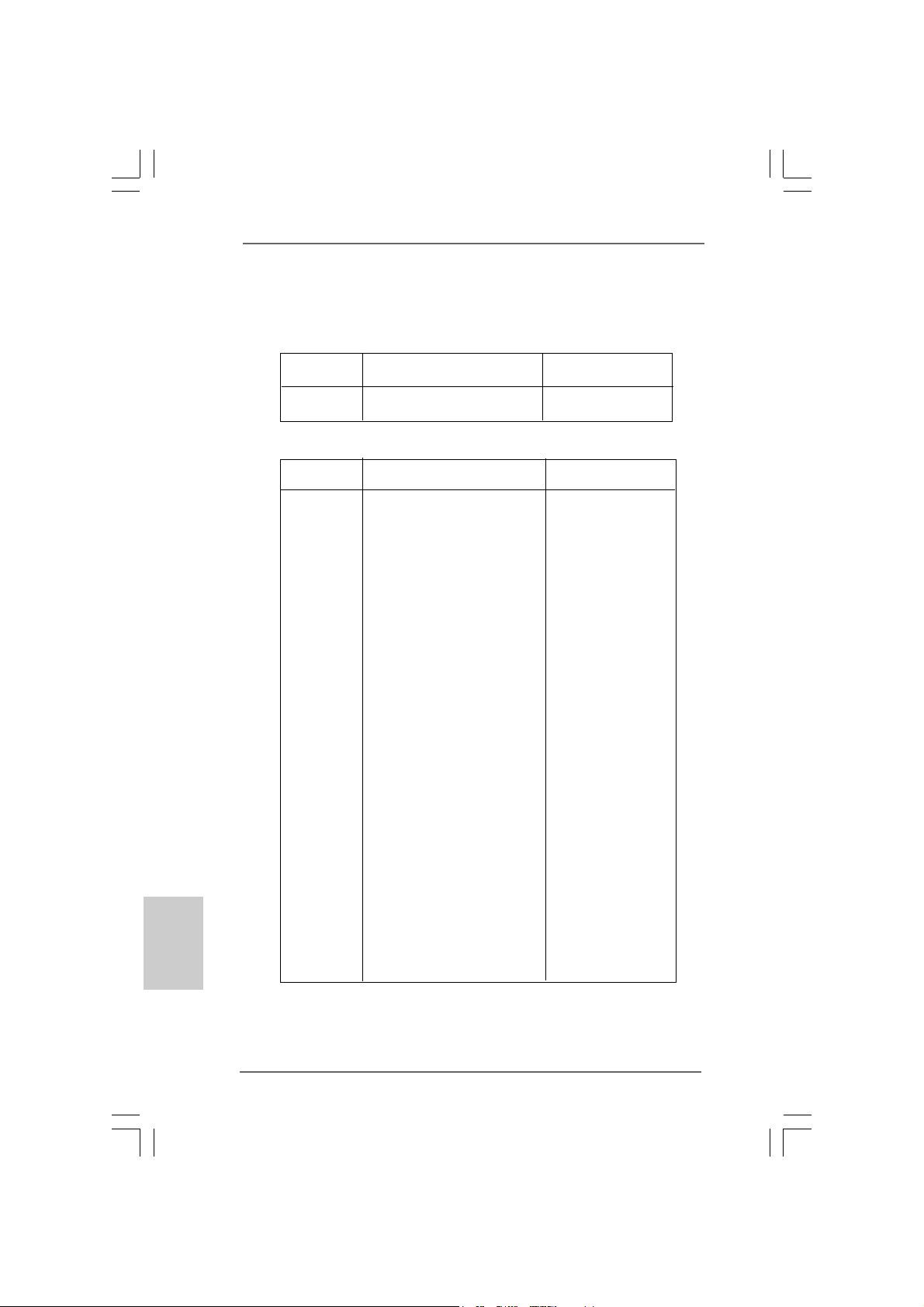
5. Veuillez vérifier dans le tableau ci-dessous pour les fréquences de prise
en charge mémoire et les fréquences FSB UC correspondantes.
Fréquence FSB UC Fréquence de prise en charge mémoire
800 DDR266, DDR333*, DDR400
533 DDR266, DDR333
* Lorsque vous utilisez un processeur à FSB800 sur cette carte mère, le
système fonctionnera à DDR320 si vous utilisez un module mémoire
DDR333.
6. Même si cette carte mère offre un contrôle sans souci, il n’est pas
recommandé d’y appliquer un over clocking. Des fréquences de bus CPU
autres que celles recommandées risquent de rendre le système instable
ou d’endommager le CPU et la carte mère.
7. Lorsqu’une surchauffe du CPU est détectée, le système s’arrête
automatiquement. Avant de redémarrer le système, veuillez vérifier que
le ventilateur d’UC sur la carte mère fonctionne correctement et débranchez
le cordon d’alimentation, puis rebranchez-le. Pour améliorer la dissipation
de la chaleur, n’oubliez pas de mettre de la pâte thermique entre le CPU le
dissipateur lors de l’installation du PC.
8. L’emplacement AGI [ASRock Graphics Interface] est d’un design
spécial et ne prend en charge que les cartes AGP VGA compatibles.
Pour les informations concernant les cartes AGP VGA compatibles,
veuillez vous reporter à la “Liste des cartes AGP VGA prises en charge”
page 8 et page 9 (Anglais uniquement). Pour l’installation correcte de la
carte AGP VGA, veuillez vous reporter au guide d’installation page 64.
9. Etant donné que la carte AMR installée occupera la même position de
connexion externe que la carte PCI installée dans l’emplacement
“PCI3”, vous ne serez en mesure d’installer aucune carte PCI dans
l’emplacement “PCI3” si une carte AMR a déjà été installée dans
l’emplacement AMR.
5858
58
5858
ASRock ConRoe865GV Motherboard
Page 59

10. La gestion de l’alimentation pour l’USB 2.0 fonctionne bien sous
Microsoft® Windows® XP SP1; SP2/2000 SP4. Elle peut ne pas
fonctionner correctement sous Microsoft® Windows® 98/ME.
2. Installation2. Installation
2. Installation
2. Installation2. Installation
Précautions à observer avant l’installationPrécautions à observer avant l’installation
Précautions à observer avant l’installation
Précautions à observer avant l’installationPrécautions à observer avant l’installation
Veuillez tenir compte des précautions suivantes avant l’installation des
composants ou tout réglage de la carte mère.
1. Débranchez le câble d’alimentation de la prise secteur avant de toucher
à tout composant. En ne le faisant pas, vous pouvez sérieusement
endommager la carte mère, les périphériques et/ou les composants.
2. Pour éviter d’endommager les composants de la carte mère du fait de
l’électricité statique, ne posez JAMAIS votre carte mère directement
sur de la moquette ou sur un tapis. N’oubliez pas d’utiliser un bracelet
antistatique ou de toucher un objet relié à la masse avant de manipuler
les composants.
3. Tenez les composants par les bords et ne touchez pas les circuits
intégrés.
4. A chaque désinstallation de composant, placez-le sur un support
antistatique ou dans son sachet d’origine.
5. Lorsque vous placez les vis dans les orifices pour vis pour fixer la
carte mère sur le châssis, ne serrez pas trop les vis ! Vous risquez
sinon d’endommager la carte mère.
ASRock ConRoe865GV Motherboard
5959
59
5959
çaisçais
çaisçais
çais
FranFran
FranFran
Fran
Page 60

2.1 Installation du CPU2.1 Installation du CPU
2.1 Installation du CPU
2.1 Installation du CPU2.1 Installation du CPU
Pour l’installation du processeur Intel 775
broches, veuillez suivre la procédure
ci-dessous.
Avant d’insérer le processeur 775 broches dans le socket, veuillez
vérifier que la surface du processeur est bien propre, et qu’il n’y a
aucune broche tordue sur le socket. Si c’est le cas, ne forcez pas
pour insérer le processeur dans le socket. Sinon, le processeur
sera gravement endommagé.
Etape 1. Ouvrez le socle :
Etape 1-1. Dégagez le levier en appuyant sur
le crochet et en le faisant ressortir
pour dégager la languette de
retenue.
Etape 1-2. Faites tourner le levier de
chargement en position ouverte
maximum à 135 degrés.
Etape 1-3. Faites pivoter la plaque de
chargement pour l’ouvrir au
maximum à environ 100 degrés.
(Plaque de chargement)
(Barrette de contact)
Vue d’ensemble du socket 775 broches
(Corps du
socket)
Français
FrançaisFrançais
FrançaisFrançais
6060
60
6060
Etape 2. Insérez le processeur 775 broches :
Etape 2-1. Tenez le processeur par ses
bords là où se trouvent des lignes
noires
ASRock ConRoe865GV Motherboard
Ligne noire
Ligne noire
Page 61

Etape 2-2. Orientez le paquet avec le
dissipateur thermique intégré (IHS)
vers le haut. Repérez la broche 1
et les deux encoches
d’orientation.
broche 1
Encoche
d’orientation
Processeur 775 broches
Encoche
d’orientation
Pour une insertion correcte, veuillez vérifier que vous faites bien
correspondre les deux encoches d’orientation sur le processeur
avec les deux détrompeurs du socket.
Détrompeur
Etape 2-3. Mettez soigneusement en place le
processeur dans le socle en un
mouvement strictement vertical.
Etape 2-4. Vérifiez que le processeur est
bien installé dans le socle et que
les encoches d’orientation sont
dans la bonne position.
Etap e 3. Enlevez le capuchon PnP (Pick et Place) :
De l’index et du de votre main gauche,
soutenez le bord de la plaque de
chargement, engagez le PnP avec le pouce
de votre main droite, et enlevez le capuchon
du socle tout en appuyant sur le centre du
capuchon PnP pour vous aider.
broche 1
Détrompeur
Socket 775 broches
1. Il est recommandé d’utiliser la languette du capuchon ; évitez de
faire sortir le capuchon PnP.
2. Ce capuchon doit être mis en place si vous renvoyez la carte
mère pour service après vente.
Etape 4. Refermez le socle :
Etape 4-1. Faites pivoter la plaque de
chargement sur l’IHS.
Etape 4-2. Tout en appuyant doucement sur
la plaque de chargement, engagez
le levier de chargement.
ASRock ConRoe865GV Motherboard
6161
61
6161
çaisçais
çaisçais
çais
FranFran
FranFran
Fran
Page 62

Français
FrançaisFrançais
FrançaisFrançais
Etape 4-3. Fixez le levier de chargement
avec la languette de la plaque de
chargement sous la languette de
retenue du levier de chargement.
2.22.2
Installation du ventilateur du processeur etInstallation du ventilateur du processeur et
2.2
Installation du ventilateur du processeur et
2.22.2
Installation du ventilateur du processeur etInstallation du ventilateur du processeur et
dissipateur thermiquedissipateur thermique
dissipateur thermique
dissipateur thermiquedissipateur thermique
Pour une installation correcte, veuillez vous reporter aux manuels d’instructions de
votre ventilateur de processeur et de votre dissipateur thermique.
L’exemple ci-dessous illustre l’installation du dissipateur thermique pour un
processeur 775 broches.
(Appliquez le matériau d’interface thermique)
Etape 1. Appliquez le matériau d’interface thermique
au centre de IHS sur la surface du socket.
(Câbles du ventilateur du côté le plus
Etape 2. Placez le dissipateur thermique sur le socket.
Vérifiez que les câbles du ventilateur sont
orientés vers le côté le plus proche du
connecteur pour ventilateur de processeur
sur la carte mère (CPU_FAN1, voir page 2,
no. 5).
Etape 3. Alignez les attaches avec la carte mère par
les orifices.
Etape 4. Faites tourner les attaches dans le sens des
aiguilles d’une montre, puis, du pouce,
enfoncez les capuchons des attaches pour
les installer et les verrouiller. Répétez
l’opération avec les autres attaches.
Si vous enfoncez les attaches sans les faire tourner dans le sens
des aiguilles d’une montre, le dissipateur thermique ne sera pas fixé
sur la carte mère.
proche du connecteur sur la carte mère)
(Orifices des attaches ressortant)
(Enfoncez (4 endroits))
Etape 5. Connectez l’en-tête du ventilateur sur le
connecteur pour ventilateur de processeur
sur la carte mère.
6262
62
6262
ASRock ConRoe865GV Motherboard
Page 63

Etape 6. Fixez la longueur de câble en excès avec du
ruban adhésif pour vous assurer que le
câble ne gênera pas le fonctionnement du
ventilateur ou n’entrera pas en contact avec
les autres composants.
2.3 Installation des modules mémoire (DIMM)2.3 Installation des modules mémoire (DIMM)
2.3 Installation des modules mémoire (DIMM)
2.3 Installation des modules mémoire (DIMM)2.3 Installation des modules mémoire (DIMM)
La carte mère ConRoe865GV possède deux emplacements DIMM DDR (Double
Débit de données) 184 broches, et prend en charge la technologie Dual Channel
Memory. Pour la configuration Double canal, vous devez toujours installer deux
modules de mémoire identiques (mêmes marque, vitesse, dimensions et type de
chip) dan s le s emplacements DDR DIMM pour activer la technologie Dual Cha nnel
Memory. Sinon, le système fonctionnera en mode Canal unique.
Si vous installez uniquement un module de mémoire ou deux modules
de mémoire non identiques, le système ne sera pas en mesure
d’activer la technologie Dual Channel Memory.
Installation d’un module DIMMInstallation d’un module DIMM
Installation d’un module DIMM
Installation d’un module DIMMInstallation d’un module DIMM
Ayez bien le soin de débrancher l’alimentation avant d’ajouter ou de
retirer des modules DIMM ou les composants du système.
Etape 1. Déverrouillez un connecteur DIMM en poussant les taquets de maintien
vers l’extérieur.
Etap e 2 . Alignez le module DIMM sur son emplacement en faisant correspondre les
encoches du module DIMM aux trous du connecteur.
ASRock ConRoe865GV Motherboard
6363
63
6363
çaisçais
çaisçais
çais
FranFran
FranFran
Fran
Page 64

Le module DIMM s’insère uniquement dans un seul sens. Si vous
forcez le module DIMM dans son emplacement avec une mauvaise
orientation cela provoquera des dommages irrémédiables à la carte
mère et au module DIMM.
Français
FrançaisFrançais
FrançaisFrançais
Etape 3. Insérez ferm
ement le module DIMM dans son emplacement jusqu’à ce que
les clips de maintien situés aux deux extrémités se ferment complètement
et que le module DIMM soit inséré correctement.
2.4 Slots d’extension (Slots PCI, AMR, et AGI)2.4 Slots d’extension (Slots PCI, AMR, et AGI)
2.4 Slots d’extension (Slots PCI, AMR, et AGI)
2.4 Slots d’extension (Slots PCI, AMR, et AGI)2.4 Slots d’extension (Slots PCI, AMR, et AGI)
Il y a 3 slots PCI, 1 slot AMR, et 1 slot AGI sur les cartes mères ConRoe865GV.
Slots PCI: Les slots PCI sont utilisés pour installer des cartes d’extension dotées
d’une interface PCI 32 bits.
Etant donné que la carte AMR installée occupera la même position
de connexion externe que la carte PCI installée dans l’emplacement
“PCI3”, vous ne serez en mesure d’installer aucune carte PCI dans
l’emplacement “PCI3” si une carte AMR a déjà été installée dans
l’emplacement AMR.
Slot AMR: Le slot AMR est utilisé pour insérer une carte ASRock MR (optionnelle)
avec des fonctionnalités Modem v.92.
Slot AGI: L’emplacement AGI [ASRock Graphics Interface] est d’un design
spécial et ne prend en charge que les cartes AGP VGA compatibles.
Pour les informations concernant les cartes AGP VGA compatibles,
veuillez vous reporter à “Supported AGP VGA Cards List” (Liste des
cartes AGP VGA prises en charge, Anglais uniquement) page 8 et
page 9.
Pour installer une carte d’extension AGP dans le système, vous
devez vous assurer de bien installer le pilote de la carte d’extension
AGP avant d’installer le pilote VGA sur carte. Si le pilote VGA sur
carte a déjà été installé avant que vous n’installiez la carte
d’extension AGP, le système configurera automatiquement la carte
VGA intégrée comme carte graphique primaire. Dans ce cas, si
vous voulez installer la carte d’extension AGP, vous avez besoin
d’abord supprimer le pilote VGA sur carte, puis installer la carte
d’extension AGP et son pilote. Pour connaître les instructions
détaillées, veuillez vous référer aux documents contenus sur le CD
de support, “Guide d’Installation du Slot AGI (pour Windows 2000) “
et “Guide d’Installation du Slot AGI (pour Windows XP) “, qui se
trouvent dans le dossier suivant :
..\ Easy Dual Monitor
6464
64
6464
ASRock ConRoe865GV Motherboard
Page 65

Installation d’une carte d’extensionInstallation d’une carte d’extension
Installation d’une carte d’extension
Installation d’une carte d’extensionInstallation d’une carte d’extension
Etape 1. Avant d’installer les cartes d’extension, veuillez vous assurer de bien
avoir coupé l’alimentation ou d’avoir débranché le cordon d’alimentation.
Veuillez lire la documentation des cartes d’extension et effectuer les
réglages matériels nécessaires pour les cartes avant de débuter
l’installation.
Etape 2. Retirez l’équerre correspondant au connecteur que vous voulez utiliser.
Gardez la vis pour un usage ultérieur.
Etap e 3. Alignez la carte sur le connecteur et appuyez fermement jusqu’à l’insertion
complète de la carte dans son emplacement.
Etape 4. Fixez la carte sur le châssis à l’aide d’une vis.
2.5 “Easy Dual Monitor”2.5 “Easy Dual Monitor”
2.5 “Easy Dual Monitor”
2.5 “Easy Dual Monitor”2.5 “Easy Dual Monitor”
Grâce à la technologie AGI8X brevetée d’ASRock, cette carte mère prend en
charge la mise à niveau Easy Dual Monitor. Avec la carte VGA interne sur carte et
la carte VGA AGP complémentaire externe, vous pouvez facilement profiter de la
fonction Dual Monitor (Double moniteur). Pour les instructions détaillées, veuillez
vous reporter au document qui se trouve sur le chemin suivant dans le CD
d’assistance :
..\ Easy Dual Monitor
2.6 Réglage des cavaliers2.6 Réglage des cavaliers
2.6 Réglage des cavaliers
2.6 Réglage des cavaliers2.6 Réglage des cavaliers
L’illustration explique le réglage des cavaliers.
Quand un capuchon est placé sur les broches,
le cavalier est « FERME ». Si aucun capuchon
ne relie les broches,le cavalier est « OUVERT ».
L’illustration montre un cavalier à 3 broches dont
les broches 1 et 2 sont “FERMEES” quand le
capuchon est placé sur ces 2 broches.
Ferme Ouvert
Le cavalier Description
PS2_USB_PWR1 Court-circuitez les broches 2
(voir p.2 No. 1) et 3 pour choisir +5VSB
(standby) et permettre aux
périphériques PS/2 ou USB de
réveiller le système.
Note: Pour sélectionner +5VSB, il faut obligatoirement 2 Amp et un courant
standby supérieur fourni par l’alimentation.
ASRock ConRoe865GV Motherboard
6565
65
6565
çaisçais
çaisçais
çais
FranFran
FranFran
Fran
Page 66

Cavaliers JR1 / JL1
(voir p.2 No. 23)
Note: Si les cavaliers JR1 et JL1 sont en court-circuit, les connecteurs audio des
panneaux avant et arrière peuvent fonctionner.
Effacer la CMOS
(CLRCMOS0)
(voir p.2 No. 17)
Note: CLRCMOS0 vous permet d’effacer les données de la CMOS. Ces données
incluent les informations système telles que le mot de passe, la date, l’heure,
et les paramètres du système. Pour restaurer les paramètres système à leur
valeur par défaut, éteignez l’ordinateur et débranchez le câble
d’alimentation. Puis placez un cavalier sur les pins CLRCMOS0 pendant 5
secondes. N’oubliez pas de retirer le cavalier avant après avoir restauré le
CMOS.
le cavalier à 2 broches
Français
FrançaisFrançais
FrançaisFrançais
6666
66
6666
ASRock ConRoe865GV Motherboard
Page 67

2.7 En-têtes et Connecteurs sur Carte2.7 En-têtes et Connecteurs sur Carte
2.7 En-têtes et Connecteurs sur Carte
2.7 En-têtes et Connecteurs sur Carte2.7 En-têtes et Connecteurs sur Carte
Les en-têtes et connecteurs sur carte NE SONT PAS des cavaliers.
NE PAS placer les capuchons de cavalier sur ces en-têtes et
connecteurs. Le fait de placer les capuchons de cavalier sur les entêtes et connecteurs causera à la carte mère des dommages
irréversibles!
Connecteur du lecteur
de disquette
(FLOPPY1 br. 33)
(voir p.2 No. 19)
Note: Assurez-vous que le côté avec fil rouge du câble est bien branché sur le
côté Broche1 du connecteur.
Connecteur IDE primaire (bleu) Connecteur IDE secondaire (noir)
(IDE1 br. 39, voir p.2 No. 8) (IDE2 br. 39, voir p.2 No. 7)
connecteur bleu connecteur noir
vers la carte mère vers le disque dur
Câble ATA 66/100 80 conducteurs
Note: Si vous utilisez seulement un périphérique IDE sur cette carte mère, veuillez
configurer le périphérique IDE comme “Maître”. Veuillez vous reporter aux
instructions du fabricant de votre IDE périphérique pour les détails. En outre,
pour optimiser la compatibilité et les performances, veuillez connecter votre
unité de disque dur sur le connecteur IDE principal (IDE1, bleu) et votre CDROM sur le connecteur IDE secondaire (IDE2, noir).
le côté avec fil rouge côté Broche1
Connecteurs Série ATA Ces deux connecteurs Série
(SAT A1: voir p.2 No. 12) ATA (SATA) prennent en
(SAT A2: voir p.2 No. 1 1) charge les câbles SATA pour
ASRock ConRoe865GV Motherboard
SAT A2
SAT A1
les périphériques de stockage
internes. L’interface SATA
actuelle permet des taux
transferts de données pouvant
aller jusqu’à 1,5 Gb/s.
6767
67
6767
çaisçais
çaisçais
çais
FranFran
FranFran
Fran
Page 68

Câble de données L’une des deux extrémités du
Série ATA (SATA) câble de données SATA peut
(en option) être connectée au disque dur
SATA ou au connecteur SATA
sur la carte mère.
Cordon d’alimentation Veuillez connecter l’extrémité
Série ATA (SAT A) noire du cordon d’alimentation
(en option) SATA sur le connecteur
connecter au connecteur
d’alimentation du disque
dur SAT A
connecter à l’unité
d’alimentation
électrique
d’alimentation sur chaque unité.
Connectez ensuite l’extrémité
blanche du cordon d’alimentation
SATA sur le connecteur
d’alimentation de l’unité
d’alimentation électrique.
En-tête USB 2.0 A côté des six ports USB
(USB_67 br.9) 2.0 par défaut sur le panneau
(voir p.2 fig. 18) E/S, il y a deux embases USB
2.0 sur cette carte mère.
Chaque emba se USB 2.0 peut
prendre en charge 2 ports USB
2.0. Cet en-tête USB4_5 est
partagé avec les ports USB 2.0
En-tête USB 2.0 partagé 2 et 3 sur panneau arrière E/S.
(USB4_5 br.9) Lorsque vous utilisez les ports
(voir p.2 fig. 28) USB du panneau frontal en
connectant le câble USB du
panneau frontal à cet en-tête
(USB4_5), les ports USB 4 et 5
sur panneau arrière E/S ne
pourront pas fonctionner.
Français
FrançaisFrançais
FrançaisFrançais
6868
68
6868
En-tête du module infrarouge Cet en-tête supporte un module
(IR1 br.5) infrarouge optionnel de
(voir p.2 No. 16) transfert et de réception sans
fil.
ASRock ConRoe865GV Motherboard
Page 69

Connecteurs audio internes Ils vous permettent de gérer des
(CD1 br. 4, AUX1 br. 4) entrées audio à partir de sources
(CD1: voir p.2 No. 25) stéréo comme un CD-ROM,
(AUX1: voir p.2 No. 24) DV D-ROM, un tuner TV ou une
AUX1
CD1
carte MPEG.
Connecteur audio panneau C’est une interface pour un câble
avant audio en façade qui permet le
(AUDIO1 br. 8) branchement et le contrôle
(voir p.2 No. 22) commodes de périphériques
audio.
En-tête du panneau système Cet en-tête permet d’utiliser
(PANEL1 br .9) plusieurs fonctions du
(voir p.2 No. 14) panneau système frontal.
En-tête du haut-parleur Veuillez connecter le
de châssis haut-parleur de châssis sur
(SPEAKER1 br. 4) cet en-tête.
(voir p.2 No. 15)
Connecteur du ventilateur Veuillez connecter le câble du
de châssis ventilateur du châssis sur ce
(CHA_FAN1 br. 3) connecteur en branchant le fil
(voir p.2 No. 13) noir sur la broche de terre.
Connecteur du ventilateur Veuillez connecter le câble de
de l’UC ventilateur d’UC sur ce
(CPU_FAN1 br. 4) connecteur et brancher le fil
(voir p.2 No. 5) noir sur la broche de terre.
ien que cette carte mère offre un support de (Ventilateur silencieux) ventilateur
de CPU à 4 broches , le ventilateur de CPU à 3 broches peut bien fonctionner
même sans la fonction de commande de vitesse du ventilateur. Si vous
prévoyez de connecter le ventilateur de CPU à 3 broches au connecteur
du ventilateur de CPU sur cette carte mère, veuillez le connecter aux broches
1-3.
1
2
3
4
Installation de ventilateur à 3 broches
Broches 1-3 connectées
ASRock ConRoe865GV Motherboard
6969
69
6969
çaisçais
çaisçais
çais
FranFran
FranFran
Fran
Page 70

En-tête d’alimentation ATX Veuillez connecter l’unité
(ATXPW R1 br. 20) d’alimentation ATX sur cet en-
(voir p.2 No. 29) tête.
En-tête de port COM Cette en-tête de port COM est
(COM1 br.9) utilisée pour prendre en charge
(voir p.2 No. 20) un module de port COM.
Connecteur ATX 12V Veuillez noter qu’il est
(ATX12V1 br .4) nécessaire de connecter une
(voir p.2 No. 2) unité d’alimentation électrique
avec une prise ATX 12V sur ce
connecteur afin qu’elle puisse
alimenter le Vcore du
processeur. Faute de quoi, il
ne sera pas possible de mettre
sous tension.
Français
FrançaisFrançais
FrançaisFrançais
7070
70
7070
ASRock ConRoe865GV Motherboard
Page 71

2.82.8
Installation des Disques Durs Serial AInstallation des Disques Durs Serial A
2.8
Installation des Disques Durs Serial A
2.82.8
Installation des Disques Durs Serial AInstallation des Disques Durs Serial A
Cette carte mère adopte un chipset south bridge Intel® ICH5 supportant les disques
durs Serial ATA (SATA). Vous pouvez installer des disques durs SATA sur cette
carte mère pour les périphériques de stockage internes. Cette section vous
guidera pour l’installation des disques durs SATA.
ETAPE 1 : Installez les disques durs SATA dans les baies pour disques de votre
châssis.
ETAPE 2 : Connectez le câble d’alimentation SATA au disque dur SATA.
ETAPE 3 : Connectez l’une des extrémités du câble de données SATA sur le
connecteur SATA de la carte mère.
ETAPE 4 : Connectez l’autre extrémité du câble de données SATA au disque dur
SATA.
Avant d’installer le système d’exploitation sur votre disque dur SATA,
vous devrez vérifier et vous assurer de la bonne configuration de
l’option“OnBoard IDE Operate Mode” dans la configuration du BIOS en
fonction de l’état de votre système. Pour les détails de la configuration,
veuillez vous reporter aux instructions à la page 31 du “Manuel de
l’utilisateur” sur le CD d’assistance.
2.92.9
Guide d’installation des pilotesGuide d’installation des pilotes
2.9
Guide d’installation des pilotes
2.92.9
Guide d’installation des pilotesGuide d’installation des pilotes
Pour installer les pilotes sur votre système, veuillez d’abord insérer le CD dans
votre lecteur optique. Puis, les pilotes compatibles avec votre système peuvent
être détectés automatiquement et sont listés sur la page du pilote du CD. Veuillez
suivre l’ordre de haut en bas sur le côté pour installer les pilotes requis. En
conséquence, les pilotes que vous installez peuvent fonctionner correctement.
TT
A (SAA (SA
T
A (SA
TT
A (SAA (SA
TT
A)A)
T
A)
TT
A)A)
2.10 La technologie de surcadençage à la volée2.10 La technologie de surcadençage à la volée
2.10 La technologie de surcadençage à la volée
2.10 La technologie de surcadençage à la volée2.10 La technologie de surcadençage à la volée
Cette carte-mère gère la technologie de surcadençage non lié, ce qui signifie que
pendant le surcadençage, le bus FSB bénéficie d’une meilleure marge en raison
du bus PCI fixe. Vous pouvez régler l’option « Fréquence d’hôte de l’UC » sur
[Auto], ce qui vous indiquera la fréquence d’hôte de l’UC courante dans l’item
suivant. Par conséquent, le bus FSB de l’UC n’est pas lié pendant le
surcadençage, mais le bus PCI est en mode fixe, si bien que le bus FSB peut
opérer dans un environnement de surcadençage plus stable.
ASRock ConRoe865GV Motherboard
7171
71
7171
çaisçais
çaisçais
çais
FranFran
FranFran
Fran
Page 72

3. Informations sur le BIOS3. Informations sur le BIOS
3. Informations sur le BIOS
3. Informations sur le BIOS3. Informations sur le BIOS
L’utilitaire de configuration BIOS est stocké dans la puce BIOS FWH. Lorsque vous
démarrez l’ordinateur, veuillez appuyer sur <F2> pendant le POST (autotest de
mise sous tension) pour accéder à l’utilitaire de configuration BIOS ; sinon, le
POST poursuit ses programmes de test. Si vous voulez accéder à l’utilitaire de
configuration BIOS après le POST, veuillez redémarrer le système en appuyant sur
<Ctrl> + <Alt> + <Supprimer>, ou en appuyant sur le bouton de réinitialisation sur le
châssis système. Pour les informations détaillées concernant l’utilitaire de
configuration BIOS, veuillez vous reporter au Manuel de l’utilisateur (fichier PDF)
contenu sur le CD d’assistance.
Français
FrançaisFrançais
FrançaisFrançais
4. Informations sur le CD de suppor4. Informations sur le CD de suppor
4. Informations sur le CD de suppor
4. Informations sur le CD de suppor4. Informations sur le CD de suppor
Cette carte mère supporte divers systèmes d’exploitation Microsoft® Windows®:
98 SE / ME / 2000 / XP. Le CD technique livré avec cette carte mère contient les
pilotes et les utilitaires nécessaires pour améliorer les fonctions de la carte mère.
Pour utiliser le CD technique, insérez-le dans le lecteur de CD-ROM. Le Menu
principal s’affiche automatiquement si “AUTORUN” est activé dans votre
ordinateur. Si le Menu principal n’apparaît pas automatiquement, localisez dans le
CD technique le fichier “ASSETUP.EXE” dans le dossier BIN et double-cliquez
dessus pour afficher les menus.
“LGA 775 CPU Installation Live Demo”
Cette carte mère est équipée d’un socket LGA 775, qui est une nouvelle interface de
socket de processeur mise sur le marché par Intel. Etant donné qu’il possède
plusieurs broches minuscules, qui sont facilement endommagées en cas de
mauvaise manipulation, ASRock a pris le soin de vous proposer un guide
d’installation clair par le biais de cette “Démo vidéo d’installation de processeur LGA
775”. Nous espérons que vous voudrez bien jeter un coup d’oeil à ce programme
vidéo de démonstration avant de commencer à installer le processeur LGA 775, de
façon à réduire les risques de dommages causés au processeur et à la carte mère du
fait d’une mauvaise manipulation. Pour voir cette Démo vidéo, vous pouvez exécuter
le Lecteur multimédia Microsoft pour lire le fichier. Vous trouverez cette Démo vidéo
dans le CD d’assistance de la carte mère sur le chemin d’accès suivant :
..\ Live Demo \ LGA 775 CPU Installation \ LGA775INST_English.DAT
tt
t
tt
7272
72
7272
ASRock ConRoe865GV Motherboard
Page 73

1. Introduzione
Grazie per aver scelto una scheda madre ASRock ConRoe865GV, una scheda
madre affidabile prodotta secondo i severi criteri di qualità ASRock. Le prestazioni
eccellenti e il design robusto si conformano all’impegno di ASRock nella ricerca della
qualità e della resistenza.
Questa Guida Rapida all’Installazione contiene l’introduzione alla motherboard e la
guida passo-passo all’installazione. Informazioni più dettagliate sulla motherboard si
possono trovare nel manuale per l’utente presente nel CD di supporto.
Le specifiche della scheda madre e il software del BIOS possono
essere aggiornati, pertanto il contenuto di questo manuale può subire
variazioni senza preavviso. Nel caso in cui questo manuale sia
modificato, la versione aggiornata sarà disponibile sul sito di ASRock
senza altro avviso. Sul sito ASRock si possono anche trovare le più
recenti schede VGA e gli elenchi di CPU supportate.
ASRock website http://www.asrock.com
1.1 Contenuto della confezione1.1 Contenuto della confezione
1.1 Contenuto della confezione
1.1 Contenuto della confezione1.1 Contenuto della confezione
Scheda madre ASRock ConRoe865GV
(Micro ATX Form Factor: 9.6-in x 8.0-in, 24.4 cm x 20.3 cm)
Guida di installazione rapida ASRock ConRoe865GV
CD di supporto ASRock ConRoe865GV
(compreso il demo installazione CPU LGA 775 )
Un cavo IDE 80-pin Ultra ATA 66/100
Un cavo per floppy drive a 1,44 Mb
Un cavo dati Serial ATA (SATA) (Opzionale)
Un cavo alimentatore HDD Serial ATA (SATA) (Opzionale)
Un ASRock I/O Plus
Una Porta COM
Una scheda ASRock MR (Opzionale)
TM
Shield
ASRock ConRoe865GV Motherboard
7373
73
7373
ItalianoItaliano
ItalianoItaliano
Italiano
Page 74

Italiano
ItalianoItaliano
ItalianoItaliano
1.21.2
SpecificheSpecifiche
1.2
Specifiche
1.21.2
SpecificheSpecifiche
Piattaforma - Micro ATX Form Factor: 9.6-in x 8.0-in, 24.4 cm x 20.3 cm
Processore - LGA 775 per Intel® CoreTM 2 Duo / Pentium® XE / Pentium® D /
Pentium® 4 / Celeron® D, con processori Conroe
(in socket 775 LGA) (vedi ATTENZIONE 1)
- FSB 800/533 MHz
- Supporto tecnologia Hyper Threading (vedi ATTENZIONE 2)
- Supporta la tecnologia overclocking “slegata”
(vedi ATTENZIONE 3)
- Supporto CPU EM64T
Chipset - Northbridge: Chipset Intel® 865GV
- Southbridge: Intel® ICH5
Memoria - Supporto tecnologia Dual Channel DDR Memory
(vedi ATTENZIONE 4)
- 2 x slot DDR DIMM
- Supporta DDR400/333/266 (vedi ATTENZIONE 5)
- Max. 2GB
Booster ibrido - Stepless control per frequenza del processore
(vedi ATTENZIONE 6)
- ASRock U-COP (vedi ATTENZIONE 7)
- Boot Failure Guard (B.F.G.)
Slot di - 3 x slot PCI
espansione - 1 x slot AGI (vedi ATTENZIONE 8)
- 1 x slot AMR (vedi ATTENZIONE 9)
VGA su scheda - Intel® Extreme Graphics 2 integrato
- VGA DirectX 8.0
- Memoria massima condivisa 96MB
Audio - C-Media 9761A Audio a 5.1 canali
LAN - Realtek PCI LAN 8101L
- Velocità: 10/100 Ethernet
- Supporta Wake-On-LAN
Pannello ASRock I/O Plus
posteriore I/O - 1 x porta PS/2 per mouse
- 1 x porta PS/2 per tastiera
- 1 x Porta VGA
- 1 x Porta parallela: supporto ECP/EPP
- 6 x porte USB 2.0 già integrate
- 1 x Porta RJ-45
- Audio Jack: Line In / Line Out / Microfono
TM
7474
74
7474
ASRock ConRoe865GV Motherboard
Page 75

Connettori - 2 x connettori SATA 1.5Go/s (Non supporta le funzioni “RAID” e
“Collegamento a caldo”)
- 2 x connettori ATA100 IDE (supporta fino a 4 dispositivi IDE)
- 1 x porta Floppy
- 1 x collettore porta COM
- 1 x connettore modulo infrarossi
- Connettore ventolina CPU/telaio
- 20-pin collettore alimentazione ATX
- 4-pin connettore ATX 12V
- Connettori audio interni
- Connettore audio sul pannello frontale
- 2 x Collettore USB 2.0 (Supporto di 4 porte USB 2,0; 2 di queste
sono condivise con le porte USB45 del pannello I/O)
(vedi ATTENZIONE 10)
BIOS - 4Mb AMI BIOS
- Suppor AMI legal BIOS
- Supporta “Plug and Play”
- Compatibile con ACPI 1.1 wake up events
- Supporta jumperfree
- Supporta SMBIOS 2.3.1
CD di - Driver, utilità, software antivirus (Versione dimostrativa)
supporto
Monitor- - Sensore per la temperatura del processore
aggio - Sensore temperatura scheda madre
Hardware - Indicatore di velocità per la ventola del processore
- Indicatore di velocità per la ventola di raffreddamento
- Ventola CPU silenziosa
- Voltaggio: +12V, +5V, +3.3V, Vcore
Compatibi- - Microsoft® Windows® 98SE / ME / 2000 / XP
lità SO
Certificazioni- FCC, CE, WHQL
ASRock ConRoe865GV Motherboard
7575
75
7575
ItalianoItaliano
ItalianoItaliano
Italiano
Page 76

Italiano
ItalianoItaliano
ItalianoItaliano
ATTENZIONE!
1. Questa scheda madre supporta CPU FSB800. Se si desidera utilizzare 2
CPU Duo CoreTM su questa scheda madre, è possibile adottare solo
processori Conroe 800 E4XXX.
2. Per il settaggio della “Tecnologia Hyper-Threading”, per favore
controllare pagina 28 del Manuale dell’utente all’interno del CD di
supporto.
3. Questa scheda madre supporta la tecnologia overclocking “slegata”.
Per i dettagli leggere “Tecnologia di Untied Overclocking” a pagina 89.
4. Questa scheda madre supporta la tecnologia Dual Channel Memory.
Prima di implementare la tecnologia Dual Channel Memory, assicurarsi
di leggere la guida all’installazione dei moduli di memoria, a pagina 81,
per seguire un’installazione appropri ata.
5. Controllare la tavola che segue per le frequenze di supporto di memoria e
le loro corrispondenti frequenze CPU FSB.
Frequenza CPU FSB Frequenza supporto di memoria
800 DDR266, DDR333*, DDR400
533 DDR266, DDR333
* Quando si utilizza una CPU FSB800 su questa scheda madre,
funzionerà a DDR320 se si adotta un modulo di memoria DDR333.
6. Anche se questa motherboard offre il controllo stepless, non si consiglia
di effettuare l’overclocking. Frequenze del bus del processore diverse
da quelle raccomandate possono causare instabilità al sistema o danni
al processore e alla scheda madre.
7. Se il processore si surriscalda, il sistema si chiude automaticamente.
Prima di riavviare il sistema, assicurarsi che la ventolina CPU della
scheda madre funzioni correttamente; scollegare e ricollegare il cavo
d’alimentazione. Per migliorare la dissipazione del calore, ricordare di
applicare l’apposita pasta siliconica tra il processore e il dissipatore
quando si installa il sistema.
8. L’alloggiamento AGI [ASRock Graphics Interface] ha un design particolare
che supporta solamente schede VGA compatibili. Per ottenere
informazioni relativamente alle schede VGA AGP compatibili, fare
riferimento alla “Lista delle schede VGA AGP supportate” di pagina 8 e 9
(Solamente in Inglese). Fare riferimento a pagina 82 della Guida
all’installazione per informazioni sull’a ppropriata installazione della scheda
VGA AGP.
9. Poiché la scheda AMR occuperà la stessa posizione di collegamento
esterno della scheda PCI, non si sarà in grado di installare alcuna
scheda PCI nell’alloggiamento “PCI3” se è già stata installata una
scheda AMR nell’alloggiamento AMR.
10. La Gestione Risorse per USB 2.0 funziona perfettamente con Microsoft
Windows® XP SP1; SP2/2000 SP4. Potrebbe dare qualche problema con
Microsoft® Windows® 98/ME.
®
7676
76
7676
ASRock ConRoe865GV Motherboard
Page 77

2. Installazione2. Installazione
2. Installazione
2. Installazione2. Installazione
Precauzioni preinstallazionePrecauzioni preinstallazione
Precauzioni preinstallazione
Precauzioni preinstallazionePrecauzioni preinstallazione
Leggere le seguenti precauzioni prima di installare componenti delle
schede madri o di cambiare le impostazioni delle schede madri.
1. Togliere il cavo dalla presa elettrica prima di toccare le
componenti. In caso contrario la schedamadre, le periferiche,
e/o i componenti possono subire gravi danni.
2. Per evitare che l’elettricità statica danneggi la scheda madre,
NON appoggiare la scheda madre su moquette, tappeti o tessuti
simili. Ricordarsi di indossare un braccialetto antistatico
collegato a terra o di toccare un oggetto posizionato a terra
prima di maneggiare le componenti.
3. Tenere i componenti per i bordi e non toccare i ICs.
4. Ogni volta che si disinstalla un componente, appoggiarlo su un
tappetino antistatico messo a terra o depositarlo nella borsa
data in dotazione con il componente.
5. Nell’usare i giraviti per fissare la scheda madre al telaio non
serrare eccessivamente le viti! Altrimenti si rischia di
danneggiare la scheda madre.
ASRock ConRoe865GV Motherboard
7777
77
7777
ItalianoItaliano
ItalianoItaliano
Italiano
Page 78

2.1 Installazione del processore2.1 Installazione del processore
2.1 Installazione del processore
2.1 Installazione del processore2.1 Installazione del processore
Attenersi alle seguenti fasi per
installare la CPU Intel 775-Pin.
Prima da inserire la CPU da 775-Pin nel socket, verificare che la
superficie della CPU sia pulita e che non ci siano pin piegati nel
socket. Non forzare l’inserimento della CPU nel socket se ci sono
pin piegati. In caso contrario la CPU potrebbe essere seriamente
danneggiata.
Fase 1. Aprire la presa:
Fase 1-1. Sbloccare la leva premendola
verso il basso ed allontanandola
dal gancio per liberare la linguetta.
Fase 1-2. Ruotare di circa 135 gradi la leva
di carico per aprirla
completamente.
Fase 1-3. Ruotare di circa 100 gradi la
piastra di carico per aprirla
completamente.
(Piastra di carica mento)
(Disposizione comandi)
(Corpo socket)
Vista del socket 775-Pin
Italiano
ItalianoItaliano
ItalianoItaliano
7878
78
7878
Fase 2. Inserire la CPU 775-Pin:
Fase 2-1. Tenere la CPU dai bordi segnati
con linee nere.
ASRock ConRoe865GV Motherboard
Linea nera
Linea nera
Page 79

Fase 2-2. Orientare il pacchetto con l’IHS
(Integrated Heat Sink: dispersore
di calore integrato) verso l’alto.
Individuare il Pin1 ed i due dentelli
chiave d’orientamento.
Pin1
Dente di
orientamento
Dente di
orientamento
T acca di allinea mento
Pin1
T acca di allinea mento
CPU da 775-Pin
Per il corretto inserimento, verificare di far combaciare i due denti
di allineamento della CPU con le due tacche nel socket.
Fase 2-3. Collocare con delicatezza la CPU
sulla presa con un movimento
puramente verticale.
Fase 2-4. Verificare che la CPU sia
all’interno della presa e combaci in
modo appropriato con le chiavi
d’orientamento.
Fase 3. Rimuovere il cappuccio PnP
(Pick and Place: prelievo e posizionamento):
Sostenere il lato della piastra di carico con
l’indice ed il pollice della mano sinistra,
appoggiare il pollice destro sul cappuccio e
farlo scivolare per rimuovere il cappuccio
dalla presa premendo sul centro del
cappuccio per assistere la rimozione.
1. Si raccomanda di utilizzare la linguetta del cappuccio per la
manipolazione ed evitare di far saltare via il cappuccio PnP.
2. Questo tappo deve essere inserito se se la scheda madre deve
essere restituita per l’assistenza.
Socket da 775-Pin
Fase 4. Chiudere la presa:
Fase 4-1. Ruotare la piastra di carico
sull’IHS.
Fase 4-2. Bloccare la leva di carico mentre
si preme leggermente sulla piastra
di carico.
ASRock ConRoe865GV Motherboard
7979
79
7979
ItalianoItaliano
ItalianoItaliano
Italiano
Page 80

Italiano
ItalianoItaliano
ItalianoItaliano
Fase 4-3. Fissare la leva di carico con la
linguetta della piastra di carico che
si trova sulla parte inferiore della
linguetta di ritenzione della leva di
carico.
2.22.2
Installazione della ventola e del dissipatore diInstallazione della ventola e del dissipatore di
2.2
Installazione della ventola e del dissipatore di
2.22.2
Installazione della ventola e del dissipatore diInstallazione della ventola e del dissipatore di
calore della CPUcalore della CPU
calore della CPU
calore della CPUcalore della CPU
Per eseguire correttamente l’installazione si rimanda ai manuali di istruzione della
ventola e del dissipatore di calore della CPU.
Di seguito viene presentato un esempio che mostra l’installazione del dissipatore
per la CPU da 775-Pin.
(Applicare il materiale dell’interfaccia termica)
Fase1. Applicare il materiale di interfaccia termica al
dell’IHS sulla superficie del socket
(Cavi della ventola sul lato più vicino
Fase 2. Collocare il dissipatore di calore nel socket.
Verificare che i cavi della ventola sono
orientati sul lato più vicino al connettore della
ventola della CPU presente sulla scheda
madre (CPU_F AN1, si veda pagin a 2, No. 5).
Fase 3. Allineare i fastener con i fori passanti della
scheda madre.
Fase 4. Ruotare i fastener in senso orario, quindi
premere il cappuccio del fastener con il
pollice per installarlo e fissarlo. Ripetere la
stessa operazione con gli altri fastener.
Se si premono i fastener verso il basso, senza ruotarli in senso
orario, il dissipatore non viene fissato bene alla scheda madre
all’header della MB)
(Fori per fastener che allineati ad
fori passa nti)
(Premere verso il basso (4 punti))
Fase 5. Collegare il cavo di alimentazione della
ventola al connettore ventola della CPU sulla
scheda madre.
8080
80
8080
ASRock ConRoe865GV Motherboard
Page 81

Fase 6. fissare il cavo in eccesso con fascette per
assicurare che il cavo non interferisca con il
funzionamento della ventola o che venga a
contatto con gli altri componenti.
2.3 Installazione dei moduli di memoria (DIMM)2.3 Installazione dei moduli di memoria (DIMM)
2.3 Installazione dei moduli di memoria (DIMM)
2.3 Installazione dei moduli di memoria (DIMM)2.3 Installazione dei moduli di memoria (DIMM)
La motherboard ConRoe865GV dispone di due slot DIMM DDR (Double Data Rate)
a 184 pin e supporta la tecnologia Dual Channel Memory. Per attivare la
configurazione Dual Channel Memory bisogna installare sempre due moduli di
memoria identici (stessa marca, velocità, dimensioni e tipo di chip) negli slot DIMM.
In caso contrario, il sistema funzionerà in modalità single channel.
Se si installa un solo modulo di memoria, oppure due moduli non
identici, non è possibile attivare la tecnologia Dual Channel Memory.
Installare una DIMMInstallare una DIMM
Installare una DIMM
Installare una DIMMInstallare una DIMM
Scollegare l’alimentazione elettrica prima di aggiungere o rimuovere i
DIMM o altri componenti del sistema.
Step 1. Sbloccare lo slot DIMM premendo i fermi che lo trattengono verso
l’esterno.
Step 2. Allineare una DIMM sullo slot così che il pettine della DIMM combaci con
la sua sede sullo slot.
La DIMM può essere montata correttamente soltanto con un
orientamento. Se si dovesse installare a forza la DIMM nello slot con
un orientamento errato, si causerebbero danni permanenti alla scheda
madre e alla DIMM stessa.
ASRock ConRoe865GV Motherboard
8181
81
8181
ItalianoItaliano
ItalianoItaliano
Italiano
Page 82

Italiano
ItalianoItaliano
ItalianoItaliano
Step 3. Inserire saldamente la DIMM nello slot fino a far scattare completamente
in posizione i fermagli di ritegno alle due estremità e fino ad installare
correttamente la DIMM nella sua sede.
2.4 Slot di espansione (Slot PCI, Slot AMR, e Slot AGI)2.4 Slot di espansione (Slot PCI, Slot AMR, e Slot AGI)
2.4 Slot di espansione (Slot PCI, Slot AMR, e Slot AGI)
2.4 Slot di espansione (Slot PCI, Slot AMR, e Slot AGI)2.4 Slot di espansione (Slot PCI, Slot AMR, e Slot AGI)
Esistono 3 slot PCI, 1 slot AMR, e 1 slot AGI su entrambe le schede madri
ConRoe865GV.
Slot PCI: Sono utilizzati per installare schede di espansione con Interfaccia PCI
a 32-bit.
Poiché la scheda AMR occuperà la stessa posizione di collegamento
esterno della scheda PCI, non si sarà in grado di installare alcuna
scheda PCI nell’alloggiamento “PCI3” se è già stata installata una
scheda AMR nell’alloggiamento AMR.
Slot AMR: Lo slot AMR permette di inserire una scheda ASRock MR (opzionale)
con funzionalità Modem v.92 Modem.
Slot AGI: L’alloggiamento AGI [ASRock Graphics Interface] ha un design
particolare che supporta solamente schede VGA compatibili. Per
ottenere informazioni relativamente alle schede VGA AGP compatibili,
fare riferimento alla “Lista delle schede VGA AGP supportate” di
pagina 8 e 9 (Solamente in Inglese).
Per installare una scheda aggiuntiva AGP sul sistema, è necessario
assicurarsi di installare il driver della scheda aggiuntiva AGP prima di
installare il driver della scheda VGA. Se il driver della scheda VGA è
stato installato prima di installare la scheda aggiuntiva AGP, il sistema
imposterà automaticamente la scheda VGA come adattatore grafico
primario. In questo caso, se si vuole installare la scheda aggiuntiva
AGP, è necessario rimuovere per prima cosa il driver della scheda
VGA, e poi installare la scheda aggiuntiva AGP ed il relativo driver. Per
istruzioni dettagliate fare riferimento ai disunenti del CD di supporto
“AGI Slot Installation Guide (for Windows 2000)” (Installazione
alloggiamento AGI per Windows 2000) e “AGI Slot Installation Guide
(for Windows XP)” (Installazione alloggiamento AGI per Windows XP),
che si trovano sul seguente percorso:
..\ Easy Dual Monitor
8282
82
8282
ASRock ConRoe865GV Motherboard
Page 83

Installare una scheda di espansione
Step 1. Prima d’installare la scheda di espansione, assicurarsi che l’alimentazione
sia stata esclusa oppure che il cavo di alimentazione sia scollegato. Prima
di iniziare l’installazione, si prega di leggere la documentazione della scheda
di espansione e di effettuare le necessarie impostazioni del hardware.
Step 2. Rimuovere i ganci sullo slot che si intende utilizzare. Tenere a portata di
mano le viti.
Step 3. Allineare il connettore della scheda con lo slot e premere con decisione
finché la scheda è completamente inserita nello slot.
Step 4. Agganciare la scheda allo chassis con le viti.
2.5 “Easy Dual Monitor”2.5 “Easy Dual Monitor”
2.5 “Easy Dual Monitor”
2.5 “Easy Dual Monitor”2.5 “Easy Dual Monitor”
Grazie alla tecnologia brevettata AGI8X ASRock, questa scheda madre supporta
l’aggiornamento Easy Dual Monitor (doppio monitor); e grazie alla scheda integrata
VGA ed alla scheda aggiuntiva esterna AGP VGA, si è in grado di godere dei
benefici della funzione Dual Monitor (doppio monitor). Fare riferimento al
documento, ubicato sul seguente percorso del CD di supporto, per istruzioni
dettagliate:
..\ Easy Dual Monitor
2.6 Setup dei Jumpers2.6 Setup dei Jumpers
2.6 Setup dei Jumpers
2.6 Setup dei Jumpers2.6 Setup dei Jumpers
L’illustrazione mostra come sono settati i
jumper. Quando il ponticello è posizionato
sui pin, il jumper è “CORTOCIRCUIT A TO”.
Se sui pin non ci sono ponticelli, il jumper
è “APERTO”. L’illustrazione mostra un
jumper a 3 pin in cui il pin1 e il pin2 sono
“CORTOCIRCUIT A TI” quando il ponticello
è posizionato su questi pin.
CORTOCIRCUIT ATO APERTO
Jumper Settaggio del Jumper
PS2_USB_PWR1 Cortocircuitare pin2, pin3 per
(vedi p.2 Nr. 1) settare a +5VSB (standby) e
abilitare PS/2 o USB wake up
events.
Nota: Per selezionare +5VSB, si richiedono almeno 2 Ampere e il consumo di
corrente in standby sarà maggiore.
ASRock ConRoe865GV Motherboard
8383
83
8383
ItalianoItaliano
ItalianoItaliano
Italiano
Page 84

Jumper JR1 / JL1
(vedi p.2 Nr. 23)
Nota: Se i jumper JR1 e JL1 sono in corto, possono funzionare i connettori audio
del pannello frontale e del pannello posteriore.
Resettare la CMOS
(CLRCMOS0)
(vedi p.2 Nr. 17)
Nota: CLRCMOS0 consente di pulire i dati nella CMOS. I dati nella CMOS includono
informazioni del setup del sistema, come per esempio la password di
sistema, la data, l’ora, e i parametri del setup di sistema. Per pulire I parametri
di sistema e resettare ai parametri di default, spegnere il computer e
scollegare l’alimentatore, poi collegare il jumper sul CLRCMOS0 per 5
secondi.
jumper a 2 pin
Italiano
ItalianoItaliano
ItalianoItaliano
8484
84
8484
ASRock ConRoe865GV Motherboard
Page 85

2.7 Collettori e Connettori su Scheda2.7 Collettori e Connettori su Scheda
2.7 Collettori e Connettori su Scheda
2.7 Collettori e Connettori su Scheda2.7 Collettori e Connettori su Scheda
I collettori ed i connettori su scheda NON sono dei jumper. NON installare
cappucci per jumper su questi collettori e connettori. L’installazione di
cappucci per jumper su questi collettori e connettori provocherà danni
permanenti alla scheda madre!
Connettore del
Floppy disk
(33-pin FLOPPY1)
(vedi p.2 Nr. 19)
Lato del Pin1 con la striscia rossa
Nota: Assicurarsi che il lato del cavo con la striscia rossa sia inserito nel lato Pin1
del connettore.
Connettore IDE primario (blu) Connettore IDE secondario (nero)
(39-pin IDE1, vedi p.2 Nr. 8) (39-pin IDE2, vedi p.2 Nr. 7)
Connettore blu Connettore nero
alla schedamadre all’hard disk drive
Cavo ATA 66/100 a 80 Pin
Nota: Se utilizzate un solo dispositivo IDE su questa scheda madre, imposta tale
dispositivo come “Master”. Fate riferimento alle istruzioni del produttore del
dispositivo IDE per maggiori dettagli. Inoltre, per ottimizzare compatibilità e
prestazioni, connettete l’hard disk al connettore primario IDE (IDE1, blu) e il
CD-ROM al connettore IDE secondario (IDE2, nero).
Connettori Serial ATA Questi due connettori Serial
(SAT A1: vedi p.2 Nr. 12) ATA (SATA) supportano cavi
(SAT A2: vedi p.2 Nr. 1 1) dati SATA per dispositivi di
SAT A2
SAT A1
immagazzina mento interni.
ATA (SATA) supportano cavi
SATA per dispositivi di memoria
interni. L’interfaccia SATA
attuale permette velocità di
trasferimento dati fino a
1.5 Gb/s.
ASRock ConRoe865GV Motherboard
8585
85
8585
ItalianoItaliano
ItalianoItaliano
Italiano
Page 86

Cavi dati Serial ATA Entrambe le estremità del cavo
(SATA) dati SATA possono collegarsi
(Opzionale) all’hard disk SATA o al
connettore SATA sulla scheda
madre.
Cavo d’alimentazione Connettete l’estremità nera del
Serial A TA (SATA) cavo di alimentazione SATA al
(Opzionale) connettore di alimentazione su
Connettere all’ailmentazione
dei dischi SAT A
Connettere al gruppo
di alimentazione
ciascun drive. Poi connettete
l’estremità bianca del cavo di
alimentazione SATA al
connettore power
dell’alimentatore.
Collettore USB 2.0 Oltre alle sei porte USB 2.0
(9-pin USB_67) predefinite nel pannello I/O, la
(vedi p.2 item 18) scheda madre dispone di due
intestazioni USB 2.0. Ciascuna
intestazione USB 2.0 supporta
due porte USB 2.0. Questo
collettore USB4_5 è condiviso
Collettore USB 2.0 con le porte USB 2.0 4 e 5 su
condiviso pannello posteriore I/O.
(9-pin USB4_5) Quando si utilizzano le porte
(vedi p.2 item 28) USB del pannello frontale,
attaccando il cavo USB
pannello frontale a questo
collettore (USB4_5), le porte 4
e 5 su pannello posteriore I/O
non saranno in grado di
funzionare.
Italiano
ItalianoItaliano
ItalianoItaliano
8686
86
8686
Collettore modulo infrarossi Questo collettore supporta
(5-pin IR1) moduli ad infrarossi optional
(vedi p.2 Nr. 16) per la trasmissione e la
ricezione senza fili.
ASRock ConRoe865GV Motherboard
Page 87

Connettori audio interni Permettono di ricevere input
(4-pin CD1, 4-pin AUX1) stereo audio da fonti di
(CD1: vedi p.2 Nr. 25) suono come CD-ROM, DVD -
(AUx1: vedi p.2 Nr. 24) ROM,TV tuner, o schede
AUX1
CD1
MPEG.
Connettore audio sul È un’interfaccia per il cavo del
pannello frontale pannello audio. Che consente
(8-pin AUDIO1) connessione facile e controllo
(vedi p.2 Nr. 22) dei dispositivi audio.
Collettore pannello di sistema Questo collettore accomoda
(9-pin PANEL1) diverse funzioni di sistema
(vedi p.2 Nr. 14) pannello frontale.
Collettore casse telaio Collegare le casse del telaio a
(4-pin SPEAKER1) questo collettore.
(vedi p.2 Nr. 15)
Connettore ventolina telaio Collegare il cavo della ventolina
(3-pin CHA_FAN1) telaio a questo connettore e far
(vedi p.2 Nr. 13) combaciare il filo nero al pin
terra.
Connettore ventolina CPU Collegare il cavo della ventolina
(4-pin CPU_FAN1) CPU a questo connettore e far
(vedi p.2 Nr. 5) combaciare il filo nero al pin
Sebbene la presente scheda madre disponga di un supporto per ventola CPU a
4 piedini (ventola silenziosa), la ventola CPU a 3 piedini è in grado di funzionare
anche senza la funzione di controllo della velocità della ventola. Se si intende
collegare la ventola CPU a 3 piedini al connettore della ventola CPU su questa
scheda madre, collegarla ai piedini 1-3.
1
2
3
4
Installazione della ventola a 3 piedini
terra.
Piedini 1-3 collegati
ASRock ConRoe865GV Motherboard
8787
87
8787
ItalianoItaliano
ItalianoItaliano
Italiano
Page 88

Connettore alimentazione ATX Collegare la sorgente
(20-pin A TXPWR1) d’alimentazione ATX a questo
(vedi p.2 Nr. 29) connettore.
Collettore porta COM Questo collettore porta COM è
(9-pin COM1) utilizzato per supportare il
(voir p.2 Nr. 20) modulo porta COM.
Connettore ATX 12 V È necessario collegare a
(4-pin A TX12V1) questo un’alimentazione con
(voir p.2 Nr. 2) spinotto ATX 12V in modo che
possa alimentare il Vcore della
CPU. In caso contrario
potrebbe venire a mancare
l’alimentazione.
Italiano
ItalianoItaliano
ItalianoItaliano
8888
88
8888
ASRock ConRoe865GV Motherboard
Page 89

2.82.8
Installazione di Hard Disk AInstallazione di Hard Disk A
2.8
Installazione di Hard Disk A
2.82.8
Installazione di Hard Disk AInstallazione di Hard Disk A
Questa scheda madre adotta il Chipset South bridge Intel® ICH5 che supporta
dischi rigidi Serial ATA (SATA). Potete installare hard disk SATA su questa scheda
madre per dispositivi di immagazzinamento interni. Questa sezione illustra come
installare hard disk SATA.
1° PASSO: Installare gli Hard Disk SATA negli spazi per le unità disco del telaio.
2° PASSO: Collegare il cavo d’alimentazione SATA al disco rigido SATA.
3° PASSO: Collegare un’estremità del cavo dati SATA al connettore SATA della
motherboard.
4° PASSO: Collegare l’altra estremità del cavo dati SATA all’hard disk SATA.
Prima di installare il sistema operativo sul disco rigido SATA, è
necessario controllare nella configurazione del BIOS che la
configurazione della modalità operativa dell’IDE su scheda sia
corretta in relazione alle condizioni del proprio sistema. Per i
dettagli sulla scongiurazione, fare riferimento alle istruzioni di
pagina 31 del “Manuale dell’utente” contenuto nel CD di supporto.
2.92.9
Guida installazione del driverGuida installazione del driver
2.9
Guida installazione del driver
2.92.9
Guida installazione del driverGuida installazione del driver
Per installare i driver nel sistema, inserire dapprima il CD in dotazione nell’unità
ottica. Quindi, i driver compatibili con il sistema vengono rilevati automaticamente
ed elencati nella pagina del driver del CD in dotazione. Per l’installazione dei driver
necessari, procedere in base ad un ordine dall’alto verso il basso. In tal modo, i
driver installati funzioneranno correttamente.
TT
A Seriali (SAA Seriali (SA
T
A Seriali (SA
TT
A Seriali (SAA Seriali (SA
TT
A)A)
T
A)
TT
A)A)
2.102.10
TT
2.10
2.102.10
La presente scheda madre supporta la tecnologia Untied Overclocking, ovvero
durante l’overclocking, FSB dispone di un margine superiore grazie ad un bus PCI
fisso. Si può impostare l’opzione “CPU Host Frequency” dell’impostazione BIOS su
[Auto] per far apparire la frequenza CPU attuale nella seguente voce. Quindi, FSB
della CPU è svincolato durante l’overclocking, ma il bus PCI si trova in modo fisso
affinché FSB possa funzionare in un ambiente di overclocking più stabile.
ecnologia di Untied Overclockingecnologia di Untied Overclocking
T
ecnologia di Untied Overclocking
TT
ecnologia di Untied Overclockingecnologia di Untied Overclocking
ASRock ConRoe865GV Motherboard
8989
89
8989
ItalianoItaliano
ItalianoItaliano
Italiano
Page 90

3. Informazioni sul BIOS3. Informazioni sul BIOS
3. Informazioni sul BIOS
3. Informazioni sul BIOS3. Informazioni sul BIOS
L’utilità di configurazione del BIOS è archiviata nel chip BIOS FWH. Quando si
avvia il computer, premere il tasto <F2> durante il POST (Power-On-Self-Test) per
accedere all’utilità di configurazione del BIOS; diversamente il POST continua con
la sua routine di controlli. Per accedere all’utilità di configurazione del BIOS dopo il
POST, riavviare il sistema premendo <Ctrl> + <Alt> + <Del>, oppure premendo il
tasto di ripristino sul telaio del sistema. Fare riferimento al Manuale dell’utente (file
PDF), contenuto nel CD di supporto, per informazioni dettagliate sull’utilità di
configurazione del BIOS.
Italiano
ItalianoItaliano
ItalianoItaliano
4. Software di suppor4. Software di suppor
4. Software di suppor
4. Software di suppor4. Software di suppor
su CDsu CD
su CD
su CDsu CD
Questa scheda madre supporta vari sistemi operativi Microsoft® Windows®: 98 SE
/ ME / 2000 / XP. Il CD di supporto a corredo della scheda madre contiene i driver
e utilità necessari a potenziare le caratteristiche della scheda.
Inserire il CD di supporto nel lettore CD-ROM. Se la funzione “AUTORUN” è attivata
nel computer, apparirà automaticamente il Menù principale. Se il Menù principale
non appare automaticamente, posizionarsi sul file “ASSETUP.EXE” nel CESTINO del
CD di supporto e cliccare due volte per visualizzare i menù.
“LGA 775 CPU Installation Live Demo”
Questa scheda madre è dotata di socket Intel LGA 775, si tratta di una nuova
interfaccia socket per CPU rilasciata da Intel. Poichè è dotata di una serie di pin
molto sottili, che possono essere facilmente rovinati se non utilizzati correttamente,
ASRock presenta una guida all’installazione molto chiara con questo “Demo
installazione CPU LGA 775”. Ci auguriamo che questo demo venga consultato prima
di procedere all’installazione della CPU LGA 775 per ridurre i rischi di danni alla CPU e
alla scheda madre derivanti da trattamenti errati. Per vedere questo Demo è
necessario eseguire Microsoft Media Player per poter riprodurre il file. Il demo si trova
nel CD di supporto della scheda madre, al seguente indirizzo:
..\ Live Demo \ LGA 775 CPU Installation \ LGA775INST_English.DAT
to e informazionito e informazioni
to e informazioni
to e informazionito e informazioni
9090
90
9090
ASRock ConRoe865GV Motherboard
Page 91

1. Introducción1. Introducción
1. Introducción
1. Introducción1. Introducción
Gracias por su compra de ASRock ConRoe865GV placa madre, una placa de
confianza producida bajo el control de calidad estricto y persistente. La placa madre
provee realización excelente con un diseño robusto conforme al compromiso de
calidad y resistencia de ASRock.
Esta Guía rápida de instalación contiene una introducción a la placa base y una guía
de instalación paso a paso. Puede encontrar una información más detallada sobre la
placa base en el manual de usuario incluido en el CD de soporte.
Porque las especificaciones de la placa madre y el software de BIOS
podrían ser actualizados, el contenido de este manual puede ser cambiado
sin aviso. En caso de cualquier modificación de este manual, la versión
actualizada estará disponible en el website de ASRock sin previo aviso.
También encontrará las listas de las últimas tarjetas VGA y CPU soportad as
en la página web de ASRock.
Website de ASRock http://www.asrock.com
1.1 Contenido de la caja1.1 Contenido de la caja
1.1 Contenido de la caja
1.1 Contenido de la caja1.1 Contenido de la caja
Placa base ASRock ConRoe865GV
(Factor forma Micro ATX: 24,4 cm x 20,3 cm, 9,6” x 8,0”)
Guía de instalación rápida de ASRock ConRoe865GV
CD de soporte de ASRock ConRoe865GV
(incluye la Demo de instalación de la CPU LGA 775)
Una cinta de datos IDE de conducción 80 Ultra ATA 66/100
Una cinta de datos para una unidad de disco de 3,5”
Un Cable de Datos Serial ATA (SATA) (Opcional)
Un cable serie ATA (SATA) de alimentación de disco duro (Opcional)
Una protección ASRock I/O Plus
Un soporte de puerto de COM
Una tarjeta ASRock MR (Opcional)
TM
ASRock ConRoe865GV Motherboard
9191
91
9191
EspañolEspañol
EspañolEspañol
Español
Page 92

Español
EspañolEspañol
EspañolEspañol
1.21.2
EspecificaciónEspecificación
1.2
Especificación
1.21.2
EspecificaciónEspecificación
Plataforma - Factor forma Micro ATX: 24,4 cm x 20,3 cm, 9,6” x 8,0”
Procesador - LGA 775 para Intel® CoreTM 2 Duo / Pentium® XE / Pentium® D /
Pentium® 4 / Celeron® D, con soporte para los procesadores
Conroe (en el paquete 775-land LGA) (ver ATENCIÓN 1)
- FSB 800/533 MHz
- Admite tecnología Hyper Threading (ver ATENCIÓN 2)
- Admite tecnología de aumento de velocidad liberada
(vea ATENCIÓN 3)
- Admite CPU EM64T
Chipset - North Bridge: Intel® 865GV
- South Bridge: Intel® ICH5
Memoria - Soporte de Tecnología de Memoria de Doble Canal
(ver ATENCIÓN 4)
- 2 x DDR DIMM slots
- Soporta DDR400/333/266 (ver ATENCIÓN 5)
- Max. 2GB
Amplificador - Stepless control de frecuencia de CPU (vea ATENCIÓN 6)
Híbrido - ASRock U-COP (vea ATENCIÓN 7)
- Protección de Falla de Inicio (B.F.G..)
Ranuras de - 3 x ranuras PCI
Expansión - 1 x ranuras AGI (vea ATENCIÓN 8)
- 1 x ranuras AMR (vea ATENCIÓN 9)
VGA OnBoard - Intel® Extreme Graphics 2 Integrado
- VGA DirectX 8.0
- 96MB de Memoria máxima compartida
Audio - C-Media 9761A 5.1 canales de Audio
LAN - Realtek PCI LAN 8101L
- Velocidad: 10/100 Ethernet
- Soporta Wake-On-LAN
Entrada/Salida ASRock I/O Plus
de Panel - 1 x puerto de ratón PS/2
Trasero - 1 x puerto de teclado PS/2
- 1 x Puerto VGA
- 1 x Puerto paralelo: soporta ECP/EPP
- 6 x puertos USB 2.0 predeterminados
- 1 x Puerto RJ-45
- Audio Jack: Line In / Line Out / Micrófono
TM
9292
92
9292
ASRock ConRoe865GV Motherboard
Page 93

Conectores - 2 x conexiones SATA, admiten una velocidad de
transferencia de datos de hasta 1,5Gb/s (No soporta las
funciones “RAID” y “Conexión en caliente”)
- 2 x ATA100 conexiones IDE
(admite hasta 4 dispositivos IDE)
- 1 x puerto Floppy
- 1x En-tête de port COM
- 1 x connecteur module infrarouge
- Conector del ventilador del CPU/chasis
- 20-pin cabezal de alimentación ATX
- 4-pin conector de ATX 12V power
- Conector de Audio Interno
- Conector de audio de panel frontal
- 2 x Cabezal USB 2.0 (admite 4 puertos USB 2,0; 2 de ellos
compartidos con puertos USB45 en el panel de E/S)
(vea ATENCIÓN 10)
BIOS - 4Mb AMI BIOS
- AMI legal BIOS
- Soporta “Plug and Play”
- ACPI 1.1 compliance wake up events
- Soporta “jumper free setup”
- Soporta SMBIOS 2.3.1
CD de soport - Controladores, Utilerías, Software de Anti Virus (Versión
de prueba)
Monitor Hardware - Sensibilidad a la temperatura del procesador
- Sensibilidad a la temperatura de la placa madre
- Taquímetros de los ventiladores del procesador y del
procesador
- Taquímetros de los ventiladores del procesador y del chasis
- Ventilador silencioso para procesador
- Monitor de Voltaje: +12V, +5V, +3.3V, Vcore
OS - En conformidad con Microsoft® Windows® 98SE / ME / 2000
/ XP
Certificaciones - FCC, CE, WHQL
EspañolEspañol
EspañolEspañol
Español
ASRock ConRoe865GV Motherboard
9393
93
9393
Page 94

Español
EspañolEspañol
EspañolEspañol
ATENCIÓN !
1. Esta placa base admite FSB800-CPU. Si desea utilizar una CPU Core
2 Duo en esta placa base, sólo podrá utilizar procesadores Conroe 800
E4XXX.
2. Por favor consulte página 28 del Manual del Usuario en el soporte CD
sobre la configuración de Hyper-Threading Technology.
3. Esta placa base admite la tecnología de aumento de velocidad liberada.
Por favor lea “Tecnología de Forzado de Reloj (Overclocking) no
relacionado” en la página 105 para obtener detalles.
4. Esta placa base soporta Tecnología de Memori a de Doble Canal. Antes de
implementar la Tecnología de Memoria de Doble Canal, asegúrese de leer
la guía de instalación de módulos de memoria en la página 99 para su
correcta instalación.
5. Compruebe la tabla siguiente para conocer la frecuencia de soporte de
memoria y su frecuencia FSB CPU correspondiente.
Frecuencia FSB CPU Frecuencia de soporte de memoria
800 DDR266, DDR333*, DDR400
533 DDR266, DDR333
* Al usar un FSB800-CPU en esta placa base, se ejecutará a DDR320 si
adquiere un módulo de memoria DDR333.
6. Aunque esta placa base ofrece un control complete, no es recomendable
forzar la velocidad. Las frecuencias de bus de la CPU distintas a las
recomendada s pueden causar inestabilidad en el sistema o dañar la CPU.
7. Cuando la temperatura de CPU está sobre-elevada, el sistema va a
apagarse automaticamente. Antes de reanudar el sistema, compruebe si
el ventilador de la CPU de la placa base funciona apropiadamente y
desconecte el cable de alimentación, a continuación, vuelva a
conectarlo. Para mejorar la disipación de calor, acuérdese de aplicar
thermal grease entre el procesador y el disipador de calor cuando usted
instala el sistema de PC.
8. La ranura AGI [ASRock Graphics Interface] es un diseño especial que
sólo admite tarjetas VGA AGP compatibles. Si desea obtener más
información sobre las tarjetas VGA AGP compatibles, consulte la
sección “Lista de tarjetas VGA AGP compatibles” en las páginas 8 y 9
(Sólo en inglés). Para obtener información sobre la instalación apropiada
de la tarjeta VGA AGP, consulte la guía de instalación de la página 100.
9. Debido a que la tarjeta AMR instalada ocupará la misma posición de
conexión externa que la tarjeta PCI instalada en la ranura “PCI3”, no
podrá instalar ninguna tarjeta PCI en la ranura “PCI3” si ya se ha
instalado una tarjeta AMR en la ranura AMR.
10. Power Management para USB 2.0 funciona bien bajo Microsoft
Windows® XP SP1; SP2/2000 SP4. Es posible que no funcione
propiamente bajo Microsoft® Windows® 98/ME.
™
®
9494
94
9494
ASRock ConRoe865GV Motherboard
Page 95

2. Instalación2. Instalación
2. Instalación
2. Instalación2. Instalación
Precaución de Pre-instalaciónPrecaución de Pre-instalación
Precaución de Pre-instalación
Precaución de Pre-instalaciónPrecaución de Pre-instalación
Tenga en cuenta las precauciones siguientes antes de instalar los
componentes de la placa base o cambiar cualquier configuración de la
placa base.
1. Desconecte el cable de electricidad antes de tocar cualquier
componente.
2. Para prevenir daño del componente de la placa madre por
electricidad estástica, NUNCA ponga su placa ma dre directamente
sobre la alfombra y otros por el estilo. Póngase la pulsera antiestástica o toquelo a cualquier objecto de tierra, por ejémplo como
el cabinete de su computador, para liberar cualquiera carga
estástica.
3. Tome componentes por la margen y no toque los ICs.
4. Ponga cualquier componente deslocalizado sobre la bolsa antiestástica que viene con la placa madre.
5. Al colocar los tornillos en sus agujeros para fijar la placa madre en
el chasis, no los apriete demasiado. Eso podría dañar la placa
madre.
2.1 Instalación de Procesador2.1 Instalación de Procesador
2.1 Instalación de Procesador
2.1 Instalación de Procesador2.1 Instalación de Procesador
Para la instalación de la CPU Intel de
775 agujas, siga los siguientes pasos.
(Matriz de contacto)
Antes de insertar la CPU de 775 agujas en el socket, compruebe
que la superficie de la CPU se encuentra limpia y no hay ninguna
aguja torcida en el socket. No introduzca la CPU en el socket por la
fuerza si se produce la situación anterior. Si lo hace, puede producir
daños graves en la CPU.
ASRock ConRoe865GV Motherboard
(Placa de carga)
Introducción al socket de 775 agujas
(Cuerpo del socket)
9595
95
9595
EspañolEspañol
EspañolEspañol
Español
Page 96

Paso 1. Abra el socket:
Paso 1-1. Suelte la palanca presionando
hacia abajo y hacia afuera en el
gancho para retirar la lengüeta de
retención.
Paso 1-2. Gire la palanca de carga hasta la
posición de apertura completa,
135 grados aproximadamente.
Paso 1-3. Gire la placa de carga hasta la
posición de apertura completa,
aproximadamente 100 grados.
Paso 2. Inserte la CPU de 775 agujas:
Paso 2-1. Sostenga la CPU por los bordes
marcados con líneas negras.
Paso 2-2. Sitúe el paquete con el IHS
(Integrated Heat Sink) mirando
hacia arriba. Busque la aguja 1 y
las dos muescas de orientación.
Línea negra
Línea negra
Español
EspañolEspañol
EspañolEspañol
9696
96
9696
aguja 1
Muesca de
orientación
aguja 1
Muesca de
orientación
CPU de 775 agujas
Para insertarla correctamente, asegúrese de que las dos muescas
de orientación de la CPU coinciden con las teclas de alineación del
socket.
T ecla de alineación
Socket de 775 agujas
Step 2-3. Coloque con cuidado la CPU en el
socket con un movimiento
totalmente vertical.
Step 2-4. Compruebe que la CPU se
encuentra en el socket y la
orientación coincide con la
indicada por las muescas.
ASRock ConRoe865GV Motherboard
Te cla de alineación
Page 97

Paso 3. Retire la cubierta PnP (Pick and Place):
Utilice los dedos índice y pulgar de su mano
izquierda para sostener el borde de la placa
de carga, introduzca el pulgar de su mano
derecha debajo de la cubierta PnP y
despéguela del socket mientras presiona en
el centro de la cubierta PnP para ayudar a
retirarla.
1. Se recomienda que utilice la lengüeta de la cubierta para retirarla,
evitando arrancar la cubierta PnP.
2. Esta cobertura debe colocarse si la placa base vuelve tras ser
reparada.
•
Paso 4. Cierre el socket:
Paso 4-1. Gire la placa de carga hacia el
IHS.
Paso 4-2. Accione la palanca de carga
mientras presiona ligeramente en
la placa de carga.
Paso 4-3. Fije la palanca de carga con la
lengüeta de la placa de carga
debajo de la lengüeta de retención
de la palanca de carga.
2.22.2
Instalación del ventilador y el disipador de la CPUInstalación del ventilador y el disipador de la CPU
2.2
Instalación del ventilador y el disipador de la CPU
2.22.2
Instalación del ventilador y el disipador de la CPUInstalación del ventilador y el disipador de la CPU
Para una correcta instalación, consulte los manuales de instrucciones del
ventilador y el disipador de la CPU.
A continuación se ofrece un ejemplo para ilustrar la instalación del disipador para
la CPU de 775 agujas.
(Aplique el material termal de interfaz)
Paso 1. Aplique el material termal de interfaz en el
centro del IHS de la superficie del socket.
ASRock ConRoe865GV Motherboard
9797
97
9797
EspañolEspañol
EspañolEspañol
Español
Page 98

Paso 2. Coloque el disipador en el socket. Asegúrese
de que los cables del ventilador están
orientados hacia el lado más cercano del
conector del ventilador de la CPU en la placa
madre (CPU_FAN1, ver página 2, nº 5).
Paso 3. Alinee los cierres con los agujeros de la
placa madre.
Paso 4. Gire el cierre en la dirección de las agujas del
reloj y, a continuación, presione las cubiertas
del cierre con el dedo pulgar para instalar y
bloquear. Repita el proceso con los cierres
restantes.
Si presiona los cierres sin girarlos en el sentido de las agujas del
reloj, el disipador no se podrá fijar a la placa madre.
Paso 5. Conecte el cabezal del ventilador con el
conector del ventilador de la CPU en la placa
madre.
Paso 6. Fije el cable que sobre con un lazo para
asegurarse de que el cable no interfiere en el
funcionamiento del ventilador y tampoco
entra en contacto con otros componentes.
(Cables del ventilador en el lado más
próximo al cabezal de la placa madre)
(Ranuras de cierre orientadas al exterior)
(Pulse (4 lugares))
Español
EspañolEspañol
EspañolEspañol
9898
98
9898
ASRock ConRoe865GV Motherboard
Page 99

2.3 Instalación de Memoria2.3 Instalación de Memoria
2.3 Instalación de Memoria
2.3 Instalación de Memoria2.3 Instalación de Memoria
La placa base ConRoe865GV proporciona dos ranuras DIMM DDR (Double Data
Rate, es decir, Tasa doble de datos) de 184 contactos y es compatible con la
Tecnología de memoria de canal dual. Para la configuración de canal dual, siempre
es necesario instalar dos módulos de memoria idénticos (la misma marca,
velocidad, tamaño y tipo de circuito impreso) en las ranuras DIMM DDR para activar
dicha tecnología. De lo contrario, el sistema funcionará en el modo de un solo
canal.
Si instala únicamente un módulo de memoria o dos módulos de
memoria que no sean idénticos, será imposible activar la Tecnología
de memoria de canal dual.
Instalación de una DIMMInstalación de una DIMM
Instalación de una DIMM
Instalación de una DIMMInstalación de una DIMM
Asegúrese de desconectar la fuente de alimentación antes de añadir o
retirar módulos DIMM o componentes del sistema.
Paso 1. Empuje los clips blancos de retención por el extremo de cada lado de la
ranura de memoria.
Paso 2. Encaje la muesca del DIMM hacia la cumbrera de la ranura.
DIMM ajusta solamente en una dirección. Si fuerza la DIMM en la
ranura con una orientación incorrecta, provocará daños permanentes
en la placa base y en la DIMM.
Paso 3. Inserte la DIMM con firmeza dentro de la ranura hasta que los clips de
sujeción de ambos lados queden completamente introducidos en su sitio y
la DIMM se haya asentado apropiadamente.
ASRock ConRoe865GV Motherboard
9999
99
9999
EspañolEspañol
EspañolEspañol
Español
Page 100

2.4 Ranuras de Expansión (Ranuras PCI, AMR, y AGI)2.4 Ranuras de Expansión (Ranuras PCI, AMR, y AGI)
2.4 Ranuras de Expansión (Ranuras PCI, AMR, y AGI)
2.4 Ranuras de Expansión (Ranuras PCI, AMR, y AGI)2.4 Ranuras de Expansión (Ranuras PCI, AMR, y AGI)
Hay 3 ranuras PCI, 1 ranura AMR, y 1 ranura AGI sobre las placas mardres
ConRoe865GV.
Ranuras PCI: Para instalar tarjetas de expansión que tienen 32-bit Interface PCI.
Debido a que la tarjeta AMR instalada ocupará la misma posición
de conexión externa que la tarjeta PCI instalada en la ranura
“PCI3”, no podrá instalar ninguna tarjeta PCI en la ranura “PCI3” si
ya se ha instalado una tarjeta AMR en la ranura AMR.
Ranura AMR: Ranura AM R se utilizar para insertar una tarjeta ASRock M R (opcional)
y funcionalidad de módem v.92.
Ranura AGI: La ranura AGI [ASRock Graphics Interface] es un diseño especial
que sólo admite tarjetas VGA AGP compatibles. Si desea obtener
más información sobre las tarjetas VGA AGP compatible s, con sulte la
sección “Lista de tarjetas VGA AGP compatibles” en las páginas 8 y
9 (Sólo en inglés).
Para instalar el sistema con una tarjeta AGP accesoria, debe
asegurarse de instalar el controlador de la tarjeta AGP accesoria
antes de instalar el controlador VGA en placa. Si el controlador VGA
en placa ya se ha instalado antes de instalar la tarjeta AGP
accesoria, el sistema establecerá automáticamente la VGA en
placa como el adaptador de gráficos primario. En dicho caso, si se
desea instalar la tarjeta AGP accesoria, debe quitarse primero el
controlador VGA en placa y, a continuación, instalarse la tarjeta
AGP accesoria y su correspondiente controlador. Para obtener
instrucciones detalladas, consulte los documentos del CD de
Soporte, “Guía de Instalación de Ranura AGI (para Windows 2000)”
y “Guía de Instalación de Ranura AGI (para Windows XP)”, que se
encuentra en la carpeta siguiente:
..\ Easy Dual Monitor
Español
EspañolEspañol
EspañolEspañol
100100
100
100100
Instalación de TInstalación de T
Instalación de T
Instalación de TInstalación de T
Paso 1. Antes de instalar la tarjeta de expansión, asegúrese de que la fuente de
alimentación está apagada o el cable de alimentación de scone cta do. Lea la
documentación que acompaña a la tarjeta de expansión y realice las
configuraciones de hardware necesarias para la tarjeta antes de iniciar la
instalación.
Paso 2. Quite la tapa que corresponde a la ranura que desea utilizar.
Paso 3. Encaje el conector de la tarjeta a la ranura. Empuje firmemente la tarjeta en
la ranura.
Paso 4. Asegure la tarjeta con tornillos.
arjetas de Expansiónarjetas de Expansión
arjetas de Expansión
arjetas de Expansiónarjetas de Expansión
ASRock ConRoe865GV Motherboard
..
.
..
 Loading...