

Page 1
Copyright Notice:Copyright Notice:
Copyright Notice:
Copyright Notice:Copyright Notice:
No part of this installation guide may be reproduced, transcribed, transmitted, or translated in any language, in any form or by any means, except duplication of documentation by the purchaser for backup purpose, without written consent of ASRock Inc.
Products and corporate names appearing in this guide may or may not be registered
trademarks or copyrights of their respective companies, and are used only for identification or explanation and to the owners’ benefit, without intent to infringe.
Disclaimer:Disclaimer:
Disclaimer:
Disclaimer:Disclaimer:
Specifications and information contained in this guide are furnished for informational
use only and subject to change without notice, and should not be constructed as a
commitment by ASRock. ASRock assumes no responsibility for any errors or omissions
that may appear in this guide.
With respect to the contents of this guide, ASRock does not provide warranty of any kind,
either expressed or implied, including but not limited to the implied warranties or
conditions of merchantability or fitness for a particular purpose. In no event shall
ASRock, its directors, officers, employees, or agents be liable for any indirect, special,
incidental, or consequential damages (including damages for loss of profits, loss of
business, loss of data, interruption of business and the like), even if ASRock has been
advised of the possibility of such damages arising from any defect or error in the guide
or product.
This device complies with Part 15 of the FCC Rules. Operation is subject to the
following two conditions:
(1) this device may not cause harmful interference, and
(2) this device must accept any interference received, including interference that
may cause undesired operation.
CALIFORNIA, USA ONLY
The Lithium battery adopted on this motherboard contains Perchlorate, a toxic
substance controlled in Perchlorate Best Management Practices (BMP) regulations
passed by the California Legislature. When you discard the Lithium battery in
California, USA, please follow the related regulations in advance.
“Perchlorate Material-special handling may apply, see
www.dtsc.ca.gov/hazardouswaste/perchlorate”
ASRock Website: http://www.asrock.com
Published January 2007
Copyright©2007 ASRock INC. All rights reserved.
ASRock ConRoe1333-DVI/H Motherboard
EnglishEnglish
EnglishEnglish
English
11
1
11
Page 2
Motherboard LMotherboard L
Motherboard L
Motherboard LMotherboard L
ayoutayout
ayout
ayoutayout
English
EnglishEnglish
EnglishEnglish
22
2
22
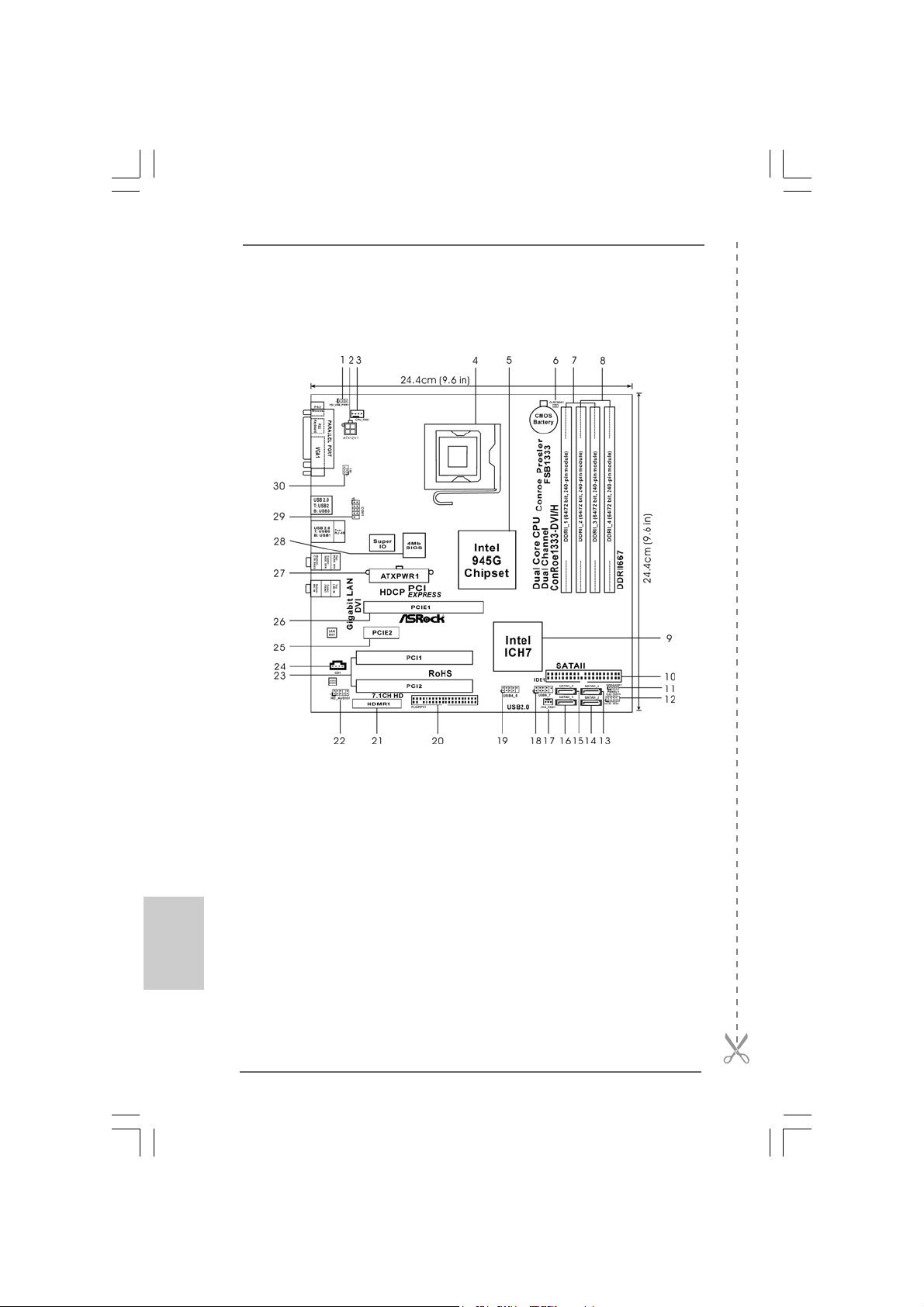
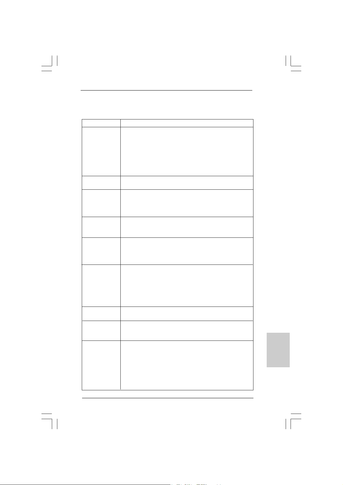
1 PS2_USB_PWR1 Jumper 15 Third SAT AII Connector (SA TAII_3; Orange)
2 A TX 12V Connector (A TX12V1) 16 Primary SAT AII Connector (SA T AII_1; Red)
3 CPU Fan Connector (CPU_FAN1) 17 Chassis Fan Connector (CHA_FAN1)
4 775-Pin CPU Socket 18 USB 2.0 Header (USB6_7, Blue)
5 North Bridge Controller 19 USB 2.0 Header (USB4_5, Blue)
6 Clear CMOS Jumper (CLRCMOS1) 20 Floppy Connector (FLOPPY1)
7 2 x 240-pin DDRII DIMM Slots 21 HDMR Slot (HDMR1)
(Dual Channel A: DDRII_1, DDRII_3; Yellow) 22 Front Panel Audio Header (HD_AUDIO1)
8 2 x 240-pin DDRII DIMM Slots 23 PCI Slots (PCI1- 2)
(Dual Channel B: DDRII_2, DDRII_4; Orange) 24 Internal Audio Connector: CD1 (Black)
9 South Bridge Controller 25 PCI Express x1 Slot
10 IDE1 Connector (IDE1, Blue) 26 PCI Express x16 Slot
11 Chassis Speaker Header (SPEAKER 1) 27 ATX Power Conne ctor (A TXPW R1)
12 System Panel Header (PANEL1) 28 BIOS FWH Chip
13 Fourth SATAII Connector (SATAII_4; Ora nge) 29 Serial Port Connector (COM1)
14 Secondary SATAII Connector (SA T AII_2; Red) 30 Infrared Module Header (IR1)
ASRock ConRoe1333-DVI/H Motherboard
Page 3
HD 8CH I/OHD 8CH I/O
HD 8CH I/O
HD 8CH I/OHD 8CH I/O
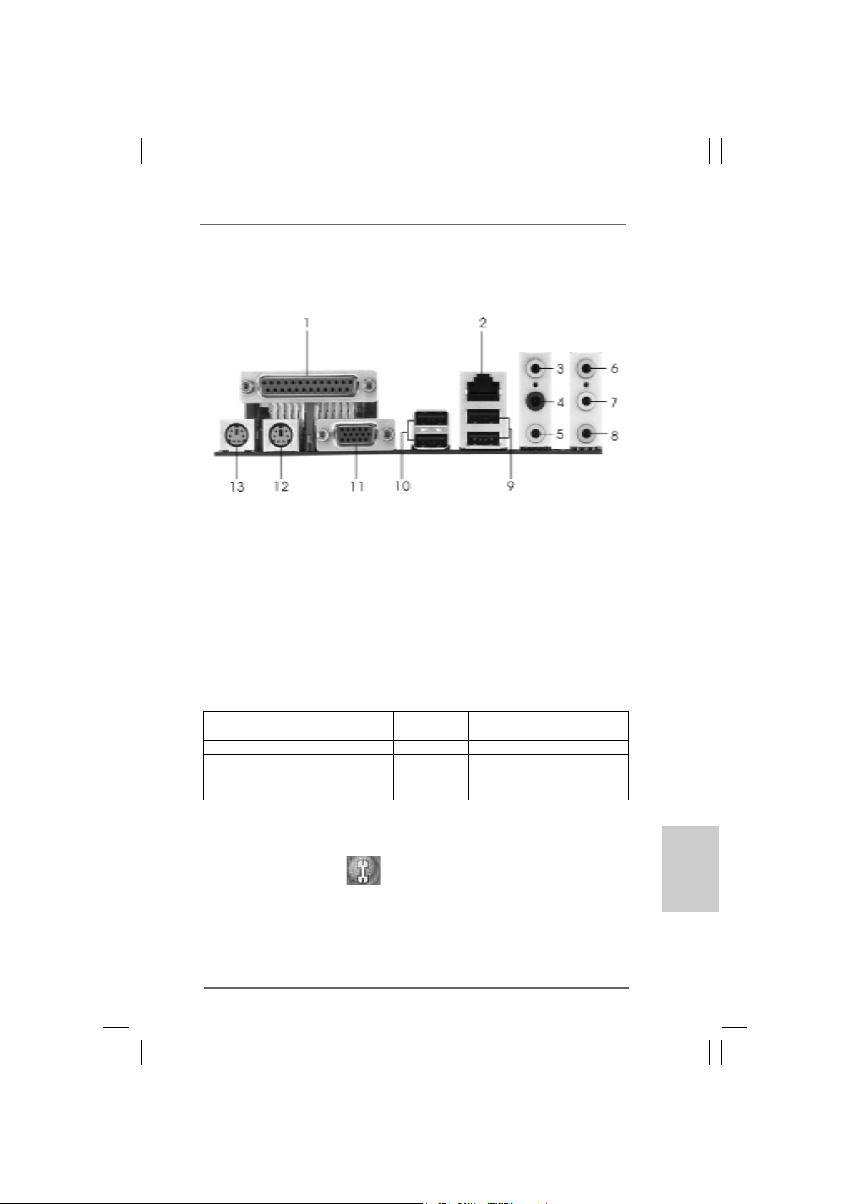
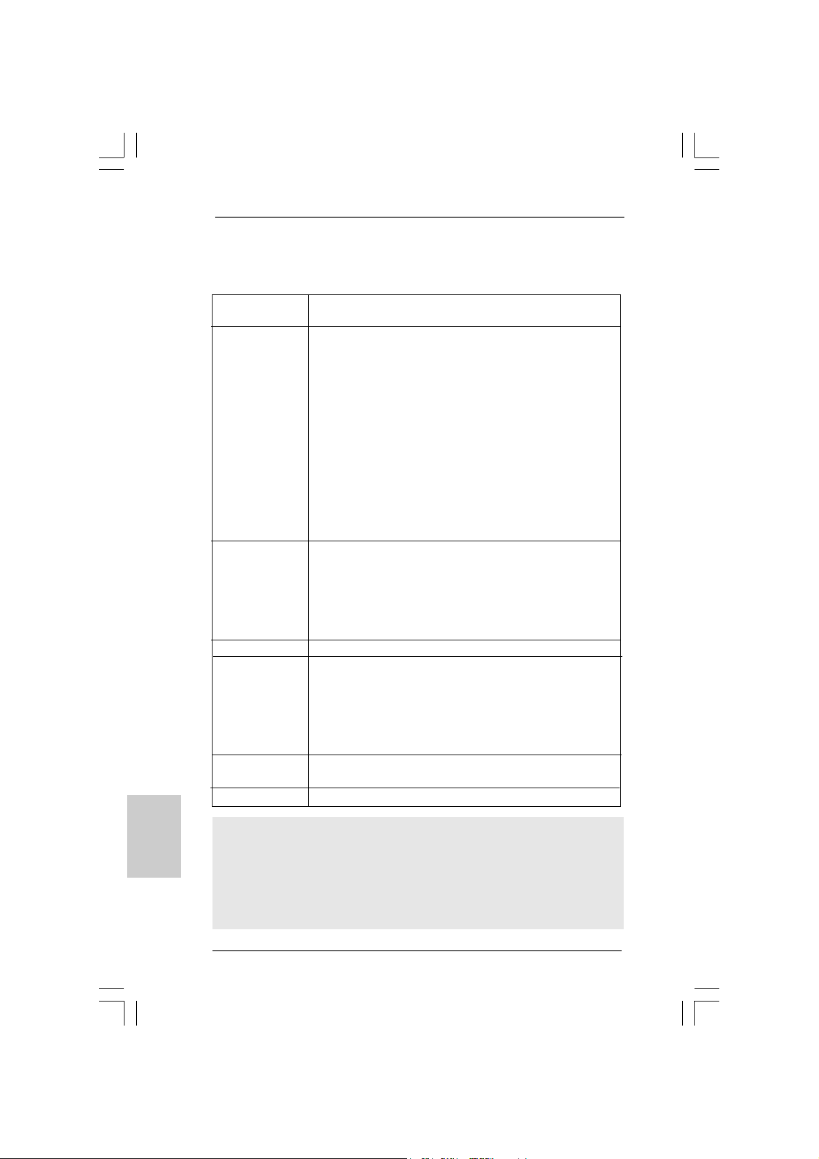
1 Parallel Port 8 Microphone (Pink)
2 RJ-45 Port 9 USB 2.0 Ports (USB01)
3 Side Speaker (Gray) 10 USB 2.0 Ports (USB23)
4 Rear Speaker (Black) 11 VG A Port
5 Central / Bass (Orange) 12 PS/2 Keyboard Port (Purple)
6 Line In (Light Blue) 13 PS/2 Mouse Port (Green)
*7 Front Speaker (Lime)
* If you use 2-channel spea ker, please connect the spe aker’s plug into “Front Speaker Jack”. See
the table below for connection details in accordance with the type of speaker you use.
TABLE for Audio Output Connection
Audio Output Channels Front Speaker Rear Speaker Central / Bass Side Speaker
(No. 7) (No. 4) (No. 5) (No. 3)
2 V -- -- -4VV---6 VVV-8 VVVV
* To enable Multi-Streaming function, you need to connect a front panel audio cable to the front
panel audio header. After restarting your computer, you will find “Mixer” tool on your system.
Please select “Mixer ToolBox” , click “Enable playback multi-streaming”, and click
“ok”. Choose “2CH”, “4CH”, “6CH”, or “8CH” and then you are allowed to select “Realtek HDA
Primary output” to use Rear Speaker, Central/Bass, and Front Speaker, or select “Realtek HDA
Audio 2nd output” to use front panel audio.
ASRock ConRoe1333-DVI/H Motherboard
EnglishEnglish
EnglishEnglish
English
33
3
33
Page 4
1. Introduction1. Introduction
1. Introduction
1. Introduction1. Introduction
Thank you for purchasing ASRock ConRoe1333-DVI/H motherboard, a reliable moth-
erboard produced under ASRock’s consistently stringent quality control. It delivers
excellent performance with robust design conforming to ASRock’s commitment to
quality and endurance.
This Quick Installation Guide contains introduction of the motherboard and step-bystep installation guide. More detailed information of the motherboard can be found in
the user manual presented in the Support CD.
Because the motherboard specifications and the BIOS software might
be updated, the content of this manual will be subject to change
without notice. In case any modifications of this manual occur, the
updated version will be available on ASRock website without further
notice. You may find the latest VGA cards and CPU support lists on
ASRock website as well.
ASRock website
1.1 Package Contents1.1 Package Contents
1.1 Package Contents
1.1 Package Contents1.1 Package Contents
ASRock ConRoe1333-DVI/H Motherboard
(Micro ATX Form Factor: 9.6-in x 9.6-in, 24.4 cm x 24.4 cm)
ASRock ConRoe1333-DVI/H Quick Installation Guide
ASRock ConRoe1333-DVI/H Support CD
One 80-conductor Ultra ATA 66/100 IDE Ribbon Cable
One Ribbon Cable for a 3.5-in Floppy Drive
One Serial ATA (SATA) Data Cable (Optional)
One Serial ATA (SATA) HDD Power Cable (Optional)
One HD 8CH I/O Shield
One COM Port Bracket
One DVI Graphics-HDCP Card
http://www.asrock.com
English
EnglishEnglish
EnglishEnglish
44
4
44
ASRock ConRoe1333-DVI/H Motherboard
Page 5
1.21.2
SpecificationsSpecifications
1.2
Specifications
1.21.2
SpecificationsSpecifications
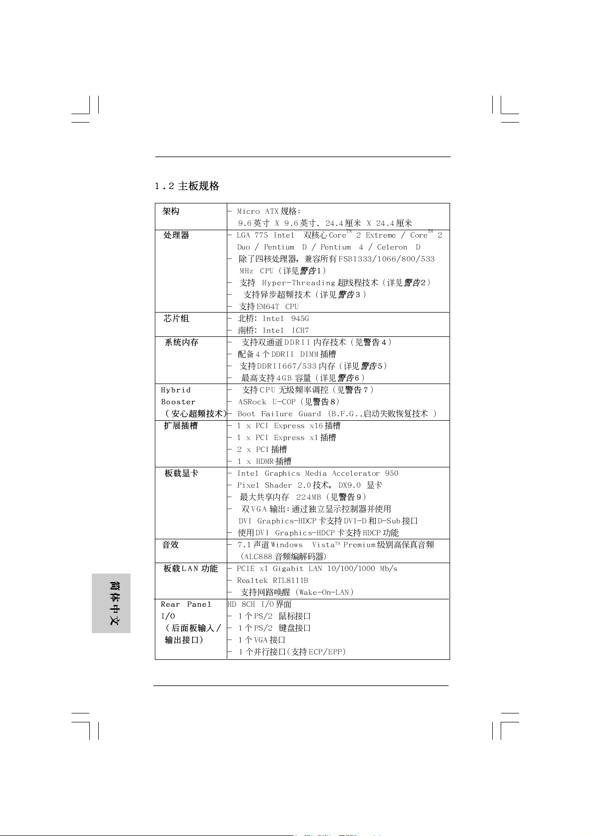
Platform - Micro ATX Form Factor: 9.6-in x 9.6-in, 24.4 cm x 24.4 cm
CPU - LGA 775 for Intel® Dual Core CoreTM 2 Extreme / CoreTM 2 Duo
/ Pentium® D / Pentium® 4 / Celeron® D
- Compatible with all FSB1333/1066/800/533MHz CPUs
except Quad Core (see CAUTION 1)
- Supports Hyper-Threading Technology (see CAUTION 2)
- Supports Untied Overclocking Technology (see CAUTION 3)
- Supports EM64T CPU
Chipset - Northbridge: Intel® 945G
- Southbridge: Intel® ICH7
Memory - Dual Channel DDRII Memory T echnology (see CAUTION 4)
- 4 x DDRII DIMM slots
- Support DDRII667/533 (see CAUTION 5)
- Max. capacity: 4GB (see CAUTION 6)
Hybrid Booster - CPU Frequency Stepless Control (see CAUTION 7)
- ASRock U-COP (see CAUTION 8)
- Boot Failure Guard (B.F.G.)
Expansion Slot - 1 x PCI Express x16 slot
- 1 x PCI Express x1 slot
- 2 x PCI slots
- 1 x HDMR slot
Graphics - Intel® Graphics Media Accelerator 950
- Pixel Shader 2.0, DirectX 9.0
- Max. shared memory 224MB (see CAUTION 9)
- Dual VGA Output: support DVI-D and D-Sub ports with DVI
Graphics-HDCP card by independent display controllers
- Supports HDCP function with DVI Gra phics-HDCP card
Audio - 7.1 CH Windows® VistaTM Premium Level HD Audio
(ALC888 Audio Codec)
LAN - PCIE x1 Giga bit LAN 10/100/1000 Mb/s
- Realtek RTL81 11B
- Supports Wake-On-LAN
Rear Panel I/O HD 8CH I/O
- 1 x PS/2 Mouse Port
- 1 x PS/2 Keyboard Port
- 1 x VGA Port
- 1 x Parallel Port (ECP/EPP Support)
- 4 x Ready-to-Use USB 2.0 Ports
- 1 x RJ-45 LAN Port
EnglishEnglish
EnglishEnglish
English
ASRock ConRoe1333-DVI/H Motherboard
55
5
55
Page 6
English
EnglishEnglish
EnglishEnglish
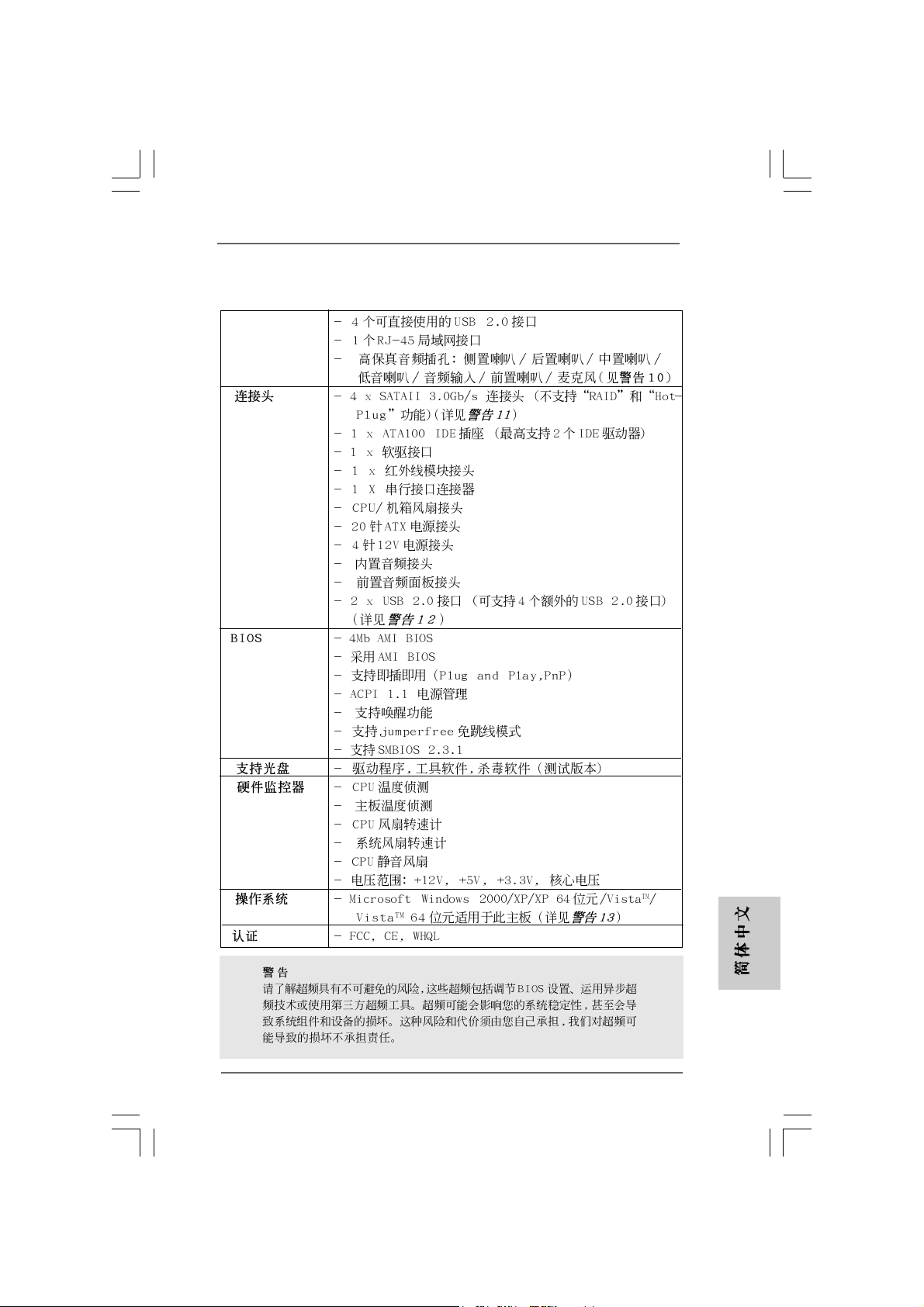
- HD Audio Jack: Side Speaker/Rear Speaker/Central/Bass/
Line in/Front Speaker/Microphone (see CAUTION 10)
Connector - 4 x SATAII 3.0 Gb/s connectors (No Support for RAID and
“Hot Plug” functions) (see CAUTION 11)
- 1 x ATA100 IDE connector (supports 2 x IDE devices)
- 1 x Floppy connector
- 1 x IR header
- 1 x COM port header
- CPU/Chassis FAN connector
- 20 pin ATX power connector
- 4 pin 12V power connector
- CD in header
- Front panel audio connector
- 2 x USB 2.0 headers (support 4 USB 2.0 ports)
(see CAUTION 12)
BIOS Feature - 4Mb AMI BIOS
- AMI Legal BIOS
- Supports “Plug and Play”
- ACPI 1.1 Compli ance Wa ke Up Events
- Supports jumperfree
- AMBIOS 2.3.1 Support
Support CD - Drivers, Utilities, AntiVirus Software (Trial Version)
Hardware - CPU Temperature Sensing
Monitor - Chassis Temperature Sensing
- CPU Fan Ta chometer
- Chassis Fan Tachometer
- CPU Quiet Fan
- Voltage Monitoring: +12V, +5V, +3.3V, Vcore
OS - Microsoft® Windows® 2000/XP/XP 64-bit/VistaTM/
VistaTM 64-bit compliant (see CAUTION 13)
Certifications - FCC, CE, WHQL
WARNING
Please realize that there is a certain risk involved with overclocking, including adjusting
the setting in the BIOS, applying Untied Overclocking Technology, or using the thirdparty overclocking tools. Overclocking may affect your system stability, or even
cause damage to the components and devices of your system. It should be done at
your own risk and expense. We are not responsible for possible damage caused by
overclocking.
66
6
66
ASRock ConRoe1333-DVI/H Motherboard
Page 7
CAUTION!
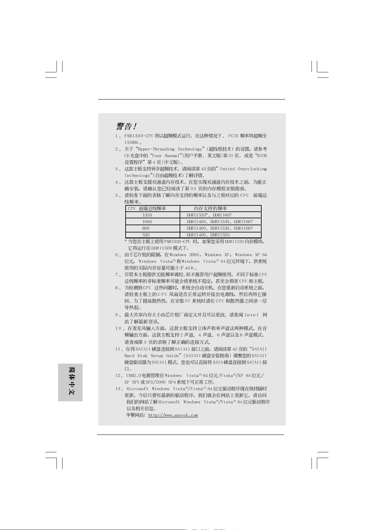
1. FSB1333-CPU will operate in overclocking mode. Under this situation,
PCIE frequency will also be overclocked to 115MHz.
2. About the setting of “Hyper Threading Technology”, please check page 31
of “User Manual” in the support CD.
3. This motherboard supports Untied Overclocking Technology. Please read
“Untied Overclocking Technology” on page 23 for details.
4. This motherboard supports Dual Channel Memory Technology. Before you
implement Dual Channel Memory Technology, make sure to read the
installation guide of memory modules on page 12 for proper installation.
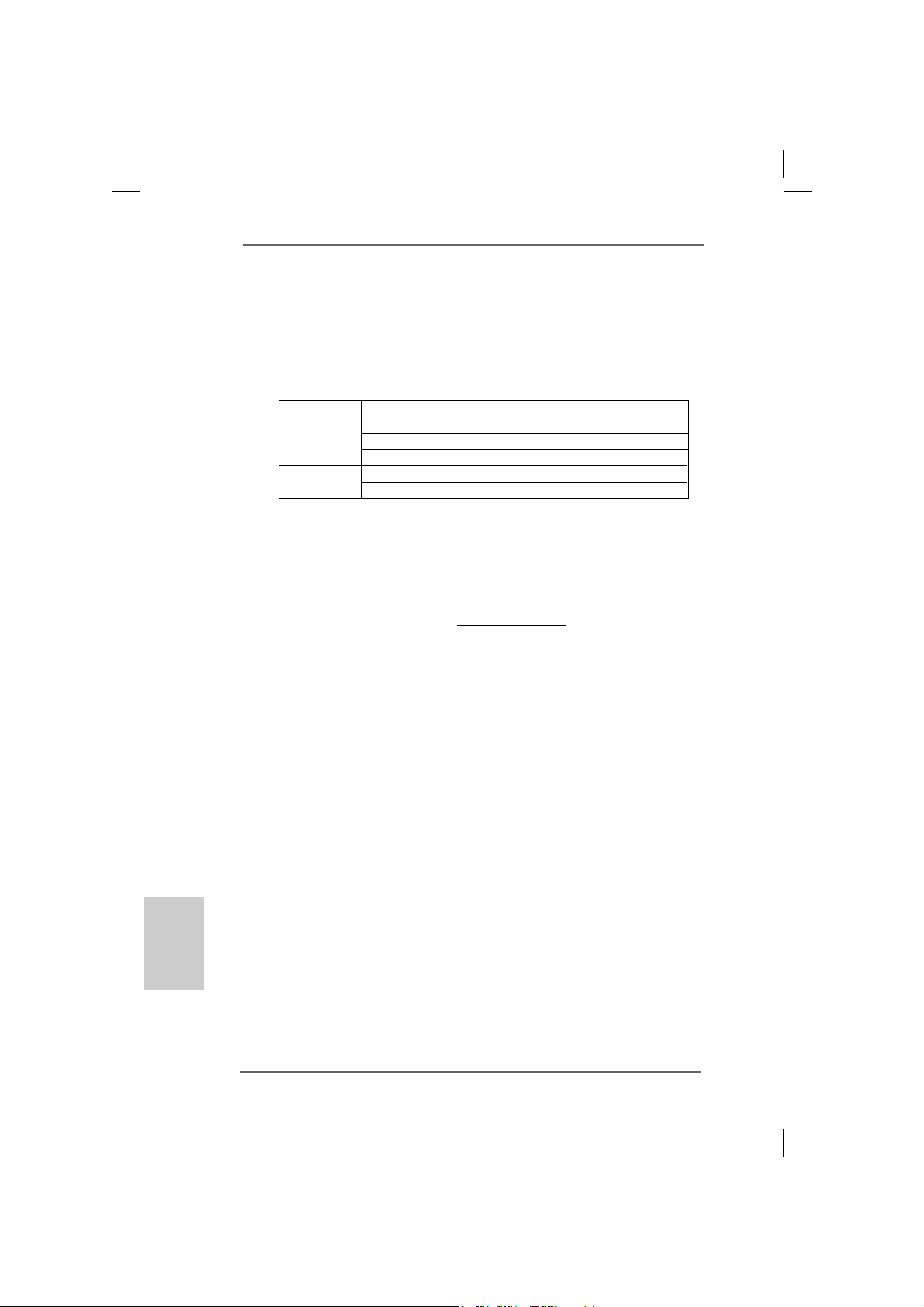
5. Please check the table below for the CPU FSB frequency and its corresponding memory support frequency.
CPU FSB Frequency Memory Support Frequency
1333 DDRII533*, DDRII667
1066 DDRII400, DDRII533, DDRII667
800 DDRII400, DDRII533, DDRII667
533 DDRII400, DDRII533
* When you use a FSB1333-CPU on this motherboard, it will run at
DDRII500 if you adopt a DDRII533 memory module.
6. Due to the chipset limitation, the actual memory size may be less than
4GB for the reservation for system usage under Windows® XP, Windows
XP 64-bit, Windows® VistaTM and Windows® VistaTM 64-bit.
7. Although this motherboard offers stepless control, it is not recommended
to perform over-clocking. Frequencies other than the recommended CPU
bus frequencies may cause the instability of the system or damage the
CPU.
8. While CPU overheat is detected, the system will automatically shutdown.
Before you resume the system, please check if the CPU fan on the
motherboard functions properly and unplug the power cord, then plug it
back again. To improve heat dissipation, remember to spray thermal
grease between the CPU a nd the he atsink when you in stall the PC system.
9. The maximum shared memory size is defined by the chipset vendor and
is subject to change. Please check Intel® website for the latest information.
10. For microphone input, this motherboard supports both stereo and mono
modes. For audio output, this motherboard supports 2-channel, 4-channel,
6-channel, and 8-channel modes. Please check the table on page 3 for
proper connection.
11. Before installing SA TAII hard disk to SATAII connector, ple ase read the “SA TAII
Hard Disk Setup Guide” on page 22 to adjust your SATAII hard disk drive to
SATAII mode. You can also connect SATA hard disk to SATAII connector
directly.
12. Power Management for USB 2.0 works fine under Microsoft® Windows
VistaTM 64-bit / VistaTM / XP 64-bit / XP SP1 or SP2 / 2000 SP4.
13. Microsoft® Windows® VistaTM / VistaTM 64-bit driver keeps on updating now. As
long as we have the latest driver, we will update it to our website in the future.
Please visit our website for Microsoft® Windows® VistaTM / VistaTM 64-bit driver
and related information.
ASRock website http://www.asrock.com
ASRock ConRoe1333-DVI/H Motherboard
®
®
EnglishEnglish
EnglishEnglish
English
77
7
77
Page 8
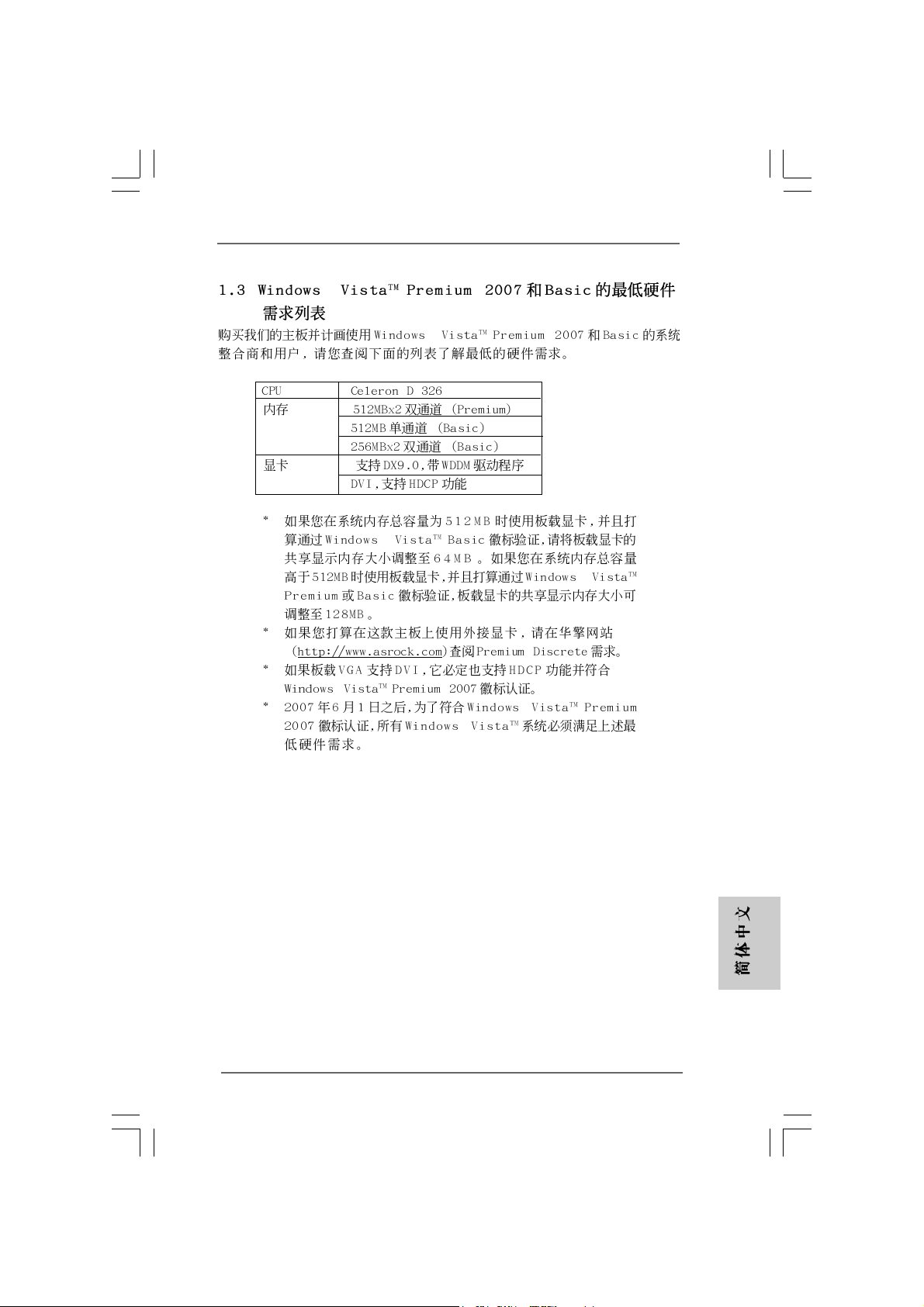
1.31.3
Minimum Hardware RMinimum Hardware R
1.3
Minimum Hardware R
1.31.3
Minimum Hardware RMinimum Hardware R
TMTM
TM
TMTM
VistaVista
Vista
VistaVista
For system integrators and users who purchase this motherboard and
plan to submit Windows® VistaTM Premium 2007 and Basic logo, please
follow below table for minimum hardware requirements.
CPU Celeron D 326
Memory 512MB x 2 Dual Channel (Premium)
VGA DX9.0 with VDDM Driver
* If you use onboard VGA with total system memory size 512MB and plan to
submit Windows® VistaTM Basic logo, please adjust the shared memory size of
onboard VGA to 64MB. If you use onboard VGA with total system memory size
above 512MB and plan to submit Windows® VistaTM Premium or Basic logo, the
shared memory size of onboard VGA can be adjusted up to 128MB.
* If you plan to use external graphics card on this motherboard, please refer to
Premium Discrete requirement at http://www.asrock.com
* If the onboard VGA supports DVI, it must also support HDCP function to qualify for
Windows® VistaTM Premium 2007 logo.
* After June 1, 2007, all Windows® VistaTM systems are required to meet above
minimum hardware requirements in order to qualify for Windows® VistaTM Premium
2007 logo.
Premium 2007 and Basic Logo Premium 2007 and Basic Logo
Premium 2007 and Basic Logo
Premium 2007 and Basic Logo Premium 2007 and Basic Logo
512MB Single Channel (Ba sic)
256MB x 2 Dual Channel (Basic)
DVI with HDCP
equirement Tequirement T
equirement T
equirement Tequirement T
able for Wable for W
able for W
able for Wable for W
indowsindows
indows
indowsindows
®®
®
®®
English
EnglishEnglish
EnglishEnglish
88
8
88
ASRock ConRoe1333-DVI/H Motherboard
Page 9
2.2.
InstallationInstallation
2.
Installation
2.2.
InstallationInstallation
Pre-installation PrecautionsPre-installation Precautions
Pre-installation Precautions
Pre-installation PrecautionsPre-installation Precautions
Take note of the following precautions before you install motherboard components or change any motherboard settings.
1. Unplug the power cord from the wall socket before touching any
component. Failure to do so may cause severe damage to the
motherboard, peripherals, and/or components.
2. To avoid damaging the motherboard components due to static
electricity, NEVER place your motherboard directly on the carpet
or the like. Also remember to use a grounded wrist strap or touch
a safety grounded object before you handle components.
3. Hold components by the edges and do not touch the ICs.
4. Whenever you uninstall any component, place it on a grounded
antstatic pad or in the bag that comes with the component.
5. When placing screws into the screw holes to secure the
motherboard to the chassis, please do not over-tighten the
screws! Doing so may damage the motherboard.
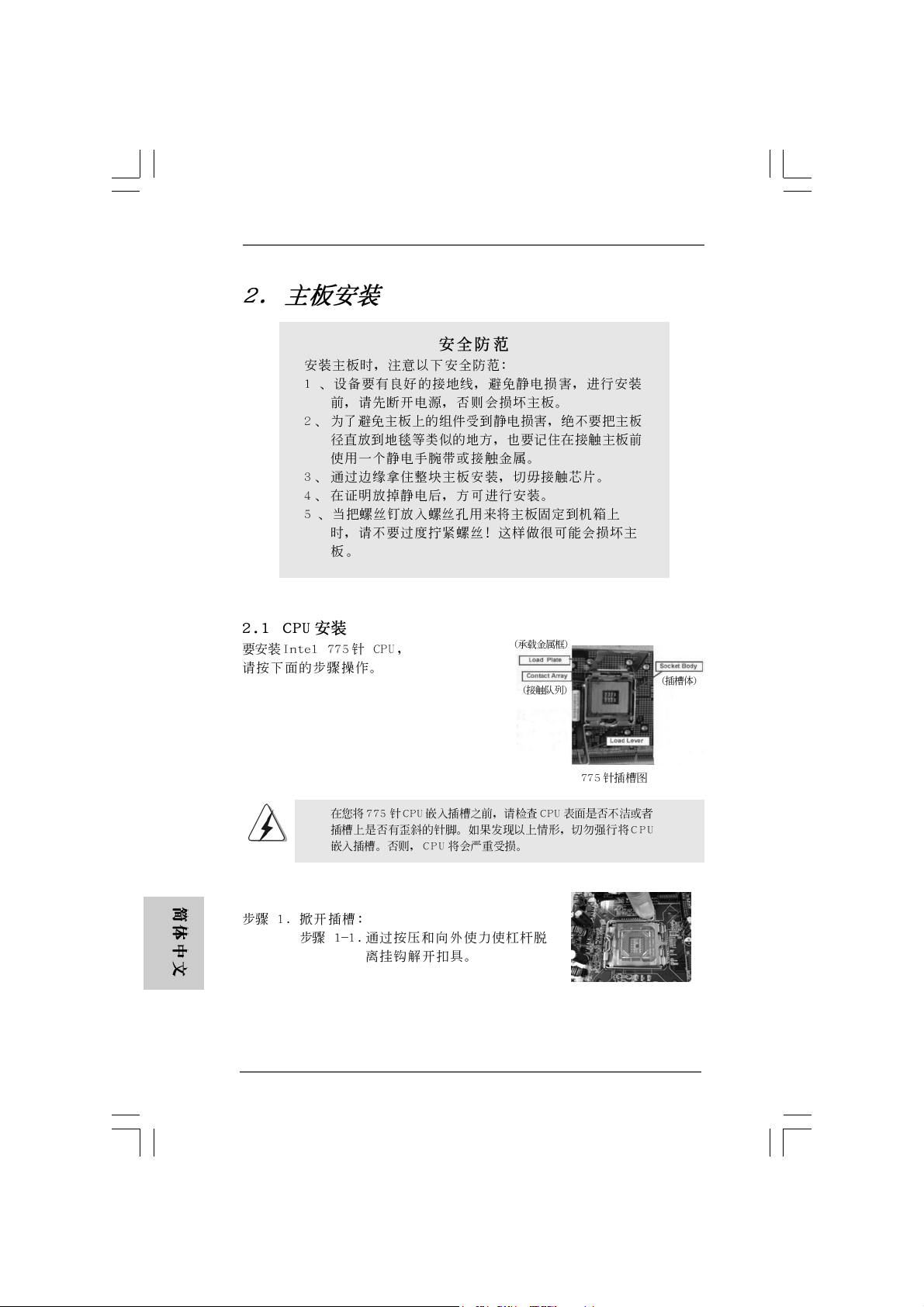
2.12.1
CPU InstallationCPU Installation
2.1
CPU Installation
2.12.1
CPU InstallationCPU Installation
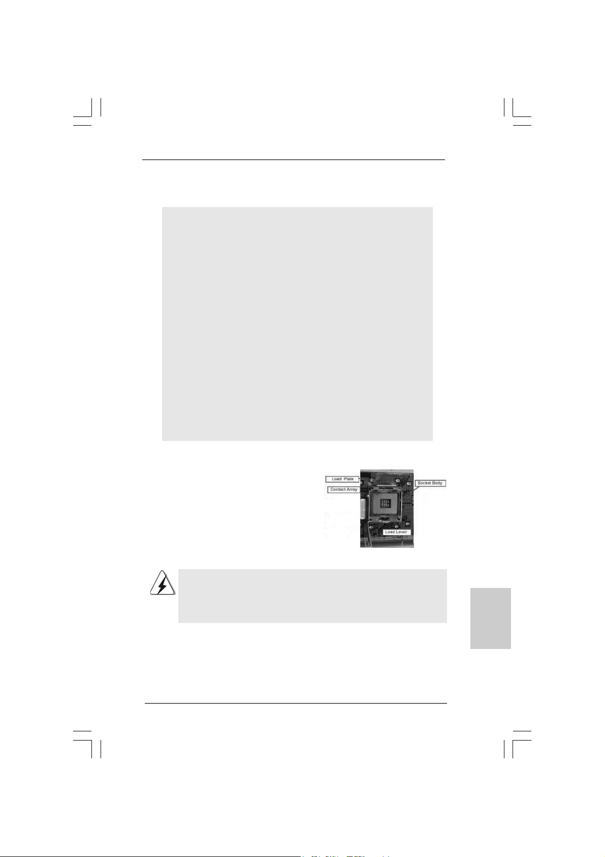
For the installation of Intel 775-LAND CPU,
please follow the steps below.
775-Pin Socket Overview
Before you insert the 775-LAND CPU into the socket, please check if
the CPU surface is unclean or if there is any bent pin on the socket.
Do not force to insert the CPU into the socket if above situation is
found. Otherwise, the CPU will be seriously damaged.
ASRock ConRoe1333-DVI/H Motherboard
EnglishEnglish
EnglishEnglish
English
99
9
99
Page 10
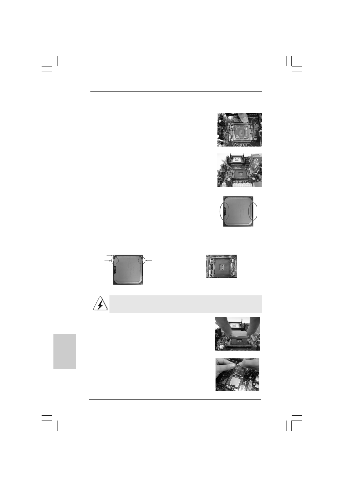
Step 1. Open the socket:
Step 1-1. Disengaging the lever by depressing
down and out on the hook to clear
retention tab.
Step 1-2. Rotate the load lever to fully open po-
sition at approximately 135 degrees.
Step 1-3. Rotate the load plate to fully open po-
sition at approximately 100 degrees.
Step 2. Insert the 775-LAND CPU:
Step 2-1. Hold the CPU by the edges where are
marked with black lines.
Step 2-2. Orient the CPU with IHS (Integrated
Heat Sink) up. Locate Pin1 and the two
orientation key notches.
Pin1
orientation
key notch
orientation
key notch
Pin1
alignment key
black line
black line
alignment key
English
EnglishEnglish
EnglishEnglish
1010
10
1010
775-Pin Socket
775-LAND CPU
For proper inserting, please ensure to match the two orientation key
notches of the CPU with the two alignment keys of the socket.
Step 2-3. Carefully pla ce the CPU into the socket
by using a purely vertical motion.
Step 2-4. Verify that the CPU is within the socket
and properly mated to the orient keys.
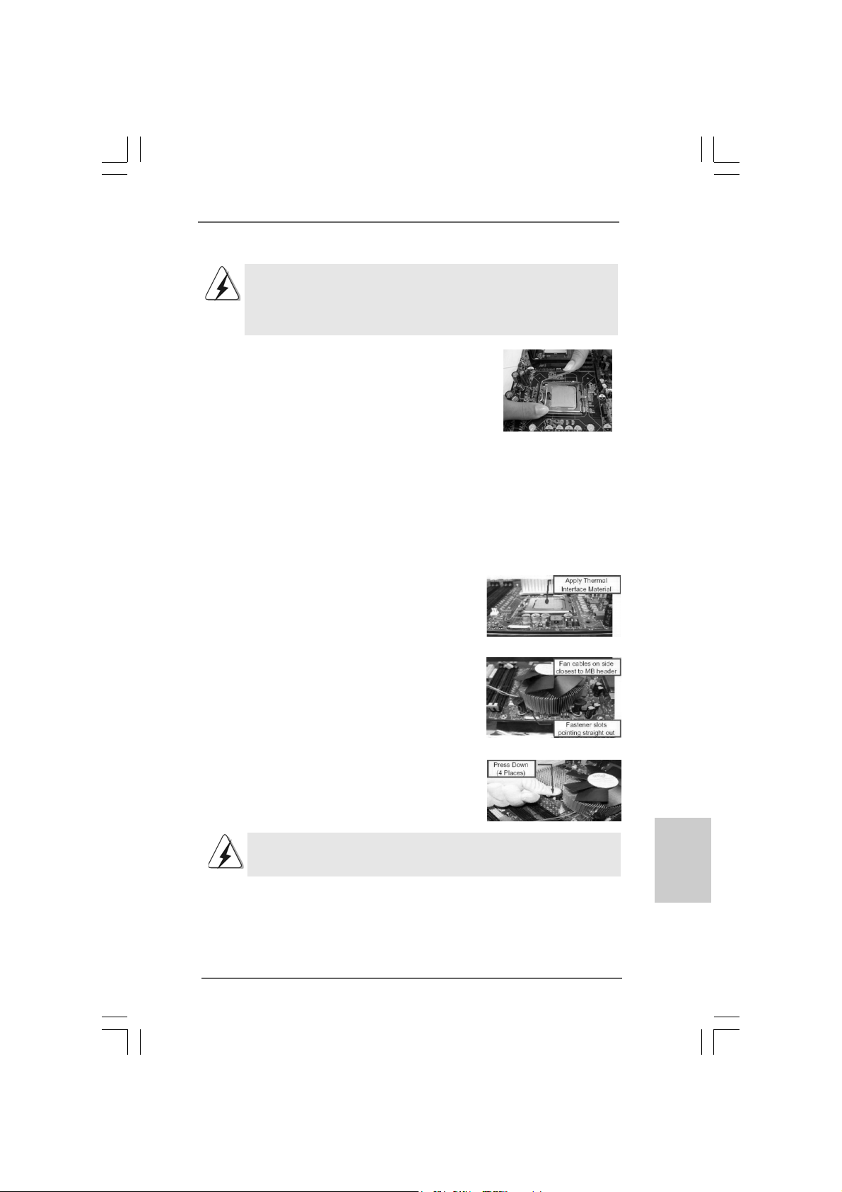
Step 3. Remove PnP Cap (Pick and Pla ce Cap):
Use your left hand index finger and thumb to
support the load plate edge, engage PnP cap
with right hand thumb and peel the cap from the
socket while pressing on center of PnP cap to
assist in removal.
ASRock ConRoe1333-DVI/H Motherboard
Page 11
1. It is recommended to use the cap tab to handle and avoid kicking
off the PnP cap.
2. This cap must be placed if returning the motherboard for after
service.
Step 4. Close the socket:
Step 4-1. Rotate the load plate onto the IHS.
Step 4-2. While pressing down lightly on load
plate, engage the load lever.
Step 4-3. Secure load lever with load plate tab
under retention tab of load lever.
2.22.2
Installation of CPU Fan and HeatsinkInstallation of CPU Fan and Heatsink
2.2
Installation of CPU Fan and Heatsink
2.22.2
Installation of CPU Fan and HeatsinkInstallation of CPU Fan and Heatsink
For proper installation, please kindly refer to the instruction manuals of your CPU fan
and heatsink.
Below is an example to illustrate the installation of the heatsink for 775-LAND CPU.
Step 1. Apply thermal interface material onto center
of IHS on the socket surface.
Step 2. Place the heatsink onto the socket. Ensure
fan cables are oriented on side closest to the
CPU fan connector on the motherboard
(CPU_FAN1, see page 2, No. 3).
Step 3. Align fasteners with the motherboard
throughholes.
Step 4. Rotate the fastener clockwise, then press
down on fastener caps with thumb to install
and lock. Repeat with remaining fasteners.
If you press down the fasteners without rotating them clockwise,
the heatsink cannot be secured on the motherboard.
Step 5. Connect fan header with the CPU fan
connector on the motherboard.
Step 6. Secure excess cable with tie-wrap to ensure
cable does not interfere with fan operation or
contact other components.
ASRock ConRoe1333-DVI/H Motherboard
1111
11
1111
EnglishEnglish
EnglishEnglish
English
Page 12
2.3 Installation of Memory Modules (DIMM)2.3 Installation of Memory Modules (DIMM)
2.3 Installation of Memory Modules (DIMM)
2.3 Installation of Memory Modules (DIMM)2.3 Installation of Memory Modules (DIMM)
ConRoe1333-DVI/H motherboard provides four 240-pin DDRII (Double Data
Rate II) DIMM slots, and supports Dual Channel Memory Technology. For dual
channel configuration, you always need to install identical (the same brand,
speed, size and chip-type) DDRII DIMM pair in the slots of the sa me color. In other
words, you have to install identical DDRII DIMM pair in Dual Cha nnel A (DDRII_1
and DDRII_3; Yellow slots; see p.2 No.7) or identical DDRII DIMM pair in Dual
Channel B (DDRII_2 and DDRII_4; Orange slots; see p.2 No.8), so that Dual
Channel Memory Technology can be activated. This motherboard also allows
you to install four DDRII DIMMs for dual channel configuration, and please install
identical DDRII DIMMs in all four slots. You may refer to the Dual Channel
Memory Configuration Table below.
Dual Channel Memory Configurations
DDRII_1 DDRII_2 DDRII_3 DDRII_4
(Yellow Slot) (Orange Slot) (Yellow Slot) (Orange Slot)
(1) Populated - Populated (2) - Populated - Populated
(3)* Populated Populated Populated Populated
* For the configuration (3), please install identical DDRII DIMMs in all four slots.
English
EnglishEnglish
EnglishEnglish
1212
12
1212
1. If you want to install two memory modules, for optimal compatibility
and reliability, it is recommended to install them in the slots of the
same color. In other words, install them either in the set of yellow
slots (DDRII_1 and DDRII_3), or in the set of orange slots (DDRII_2
and DDRII_4).
2. If only one memory module or three memory modules are installed
in the DDRII DIMM slots on this motherboard, it is unable to activate
the Dual Channel Memory T e chnology.
3. If a pair of memory modules is NOT installed in the same Dual
Channel, for exa mple, in stalling a pair of memory module s in D DRII_1
and DDRII_2, it is unable to activate the Dual Channel Memory
Technology .
4. It is not allowed to install a DDR memory module into DDRII slot;
otherwise, this motherboard and DIMM may be damaged.
ASRock ConRoe1333-DVI/H Motherboard
Page 13
Installing a DIMMInstalling a DIMM
Installing a DIMM
Installing a DIMMInstalling a DIMM
Please make sure to disconnect power supply before adding or
removing DIMMs or the system components.
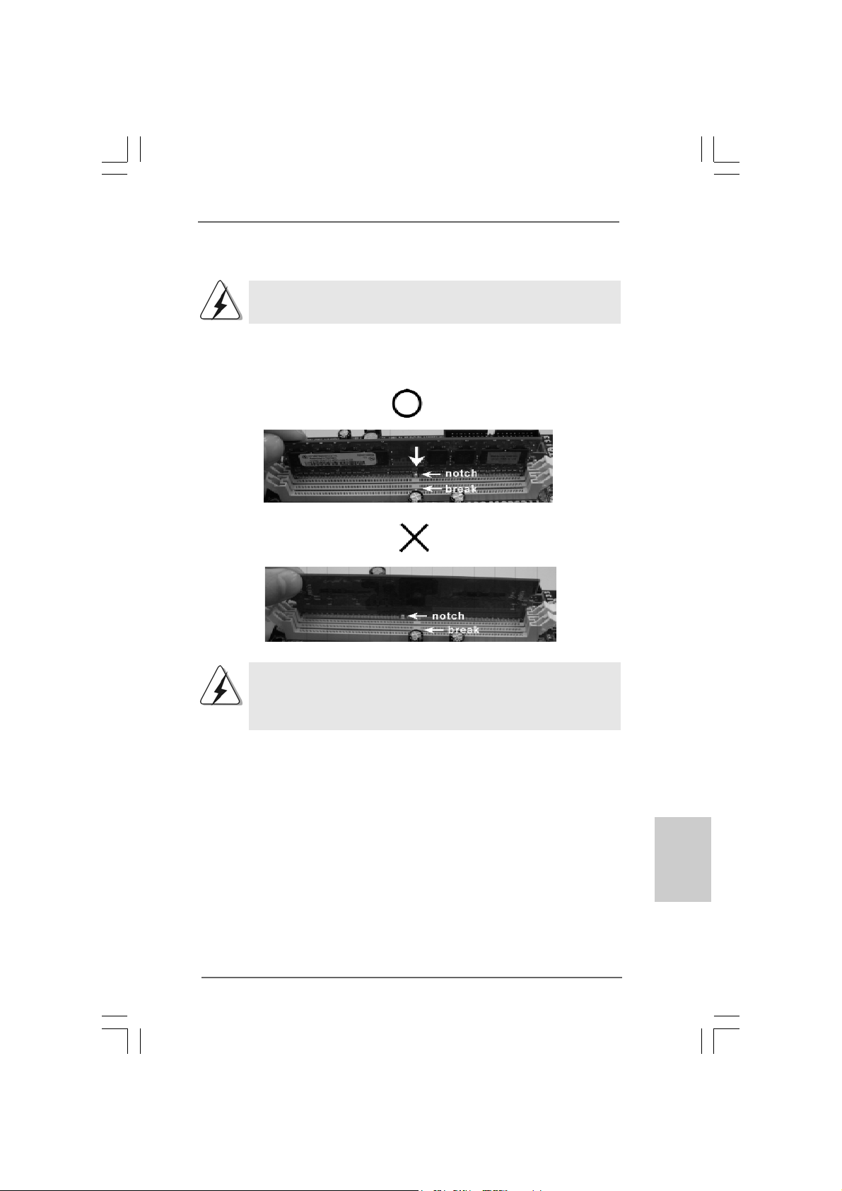
Step 1. Unlock a DIMM slot by pressing the retaining clips outward.
Step 2. Align a DIMM on the slot such that the notch on the DIMM matches the break
on the slot.
The DIMM only fits in one correct orientation. It will cause permanent
damage to the motherboard and the DIMM if you force the DIMM into the
slot at incorrect orientation.
Step 3. Firmly insert the DIMM into the slot until the retaining clips at both ends fully
snap back in place and the DIMM is properly seated.
ASRock ConRoe1333-DVI/H Motherboard
1313
13
1313
EnglishEnglish
EnglishEnglish
English
Page 14
2.4 Expansion Slots (PCI, HDMR and PCI Express Slots)2.4 Expansion Slots (PCI, HDMR and PCI Express Slots)
2.4 Expansion Slots (PCI, HDMR and PCI Express Slots)
2.4 Expansion Slots (PCI, HDMR and PCI Express Slots)2.4 Expansion Slots (PCI, HDMR and PCI Express Slots)
There are 2 PCI slots, 1 HDMR slot and 2 PCI Express slots on this motherboard.
PCI slots: PCI slots are used to install expansion cards that have the 32-bit PCI
interface.
HDMR slot: HDMR slot is used to insert a HDMR card with v.92 Modem
functionality. The HDMR slot is shared with PCI2 slot.
PCIE Slots: PCIE1 (PCIE x16 slot) is used for PCI Express cards with x16 lane
width graphics cards or ASRock DVI Graphics-HDCP card.
PCIE2 (PCIE x1 slot) is used for PCI Express cards with x1 lane
width cards, such as Gigabit LAN card, SATA2 card, etc.
1. If you install the add-on PCI Express VGA card to PCIE1 (PCIE x16 slot),
the onboard VGA will be disabled. If you install the add-on PCI Express
VGA card to PCIE1 (PCIE x16 slot) and adjust the “Internal Graphics
Mode Select” BIOS option to [Enabled], the onboard VGA will be enabled,
and the primary screen will be onboard VGA.
2. You can only choose either PCI Express VGA card or DVI Graphics-HDCP
card to install to PCIE1 (PCIE x16 slot).
Installing an expansion cardInstalling an expansion card
Installing an expansion card
Installing an expansion cardInstalling an expansion card
Step 1. Before installing the expansion card, please make sure that the power
supply is switched off or the power cord is unplugged. Please read the
documentation of the expansion card and make necessary hardware
settings for the card before you start the installation.
Step 2. Remove the bracket facing the slot that you intend to use. Keep the screws
for later use.
Step 3. Align the card connector with the slot and press firmly until the card is
completely seated on the slot.
Step 4. Fasten the card to the chassis with screws.
English
EnglishEnglish
EnglishEnglish
1414
14
1414
ASRock ConRoe1333-DVI/H Motherboard
Page 15
2.5 DVI Graphics-HDCP Card Installation Guide2.5 DVI Graphics-HDCP Card Installation Guide
2.5 DVI Graphics-HDCP Card Installation Guide
2.5 DVI Graphics-HDCP Card Installation Guide2.5 DVI Graphics-HDCP Card Installation Guide
With the onboard VGA/D-Sub output and the external installation of our DVI GraphicsHDCP card, this motherboard provides users with dual VGA output support: DVI-D
and D-Sub. You ca n easily enjoy the benefits of dual VGA output support by connecting
the D-Sub monitor to the VGA/D-Sub port on the I/O panel and connecting the DVI-D
monitor to our DVI Graphics-HDCP card inserted to PCIE1 (PCIE x16 slot) on this
motherboard. Please refer to below procedure s f or proper installation of D VI GraphicsHDCP card.
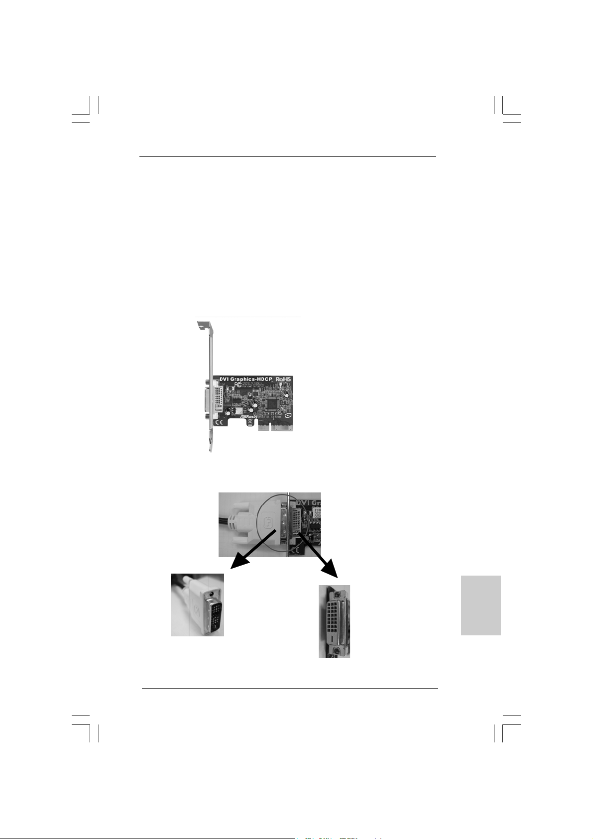
Step 1. Install the D VI Graphics-HDCP card to PCIE1 (PCIE x16 slot). Please refer to
the expansion card installation procedures on page 14 for details.
DVI Graphics-HDCP card
Step 2. Connect the DVI-D monitor to the DVI-D output connector of DVI Graphics-
HDCP card which is inserted to PCIE1 (PCIE x16 slot) on this motherboard.
DVI-D connector of
DVI-D monitor
ASRock ConRoe1333-DVI/H Motherboard
DVI-D output connector
of DVI Graphics-HDCP
card
1515
15
1515
EnglishEnglish
EnglishEnglish
English
Page 16
Step 3. Connect the D-Sub monitor to the VGA/D-Sub port on the I/O panel of this
motherboard.
Step 4. If you have installed Intel® VGA driver from our support CD to your system
already, you can freely enjoy the benefits of DVI-D output function with this
motherboard after your system boots. If you haven’t installed Intel® VGA
driver yet, please install Intel® VGA driver from our support CD to your
system and restart your computer. Then you can start to use DVI-D output
function with this motherboard.
HDCP Function with DVI Graphics-HDCP Card
HDCP function is supported with DVI Graphics-HDCP card. With the
installation of DVI Graphics-HDCP card, this motherboard is equipped
with HDCP function. To use HDCP function with this motherboard,
you need to adopt the monitor that supports HDCP function as well.
Therefore, you can enjoy the superior display quantity with highdefinition HDCP encryption contents. Please refer to below instruction for more details about HDCP function.
What is HDCP?
HDCP stands for High-Bandwidth Digital Content Protection, a
specification developed by Intel® for protecting digital entertainment
content that uses the DVI interface. HDCP is a copy protection
scheme to eliminate the possibility of intercepting digital data
midstream between the video source, or transmitter - such as a
computer, DVD player or set-top box - and the digital display, or
receiver - such as a monitor, television or projector. In other words,
HDCP specification is designed to protect the integrity of content as it
is being transmitted.
English
EnglishEnglish
EnglishEnglish
1616
16
1616
Products compatible with the HDCP scheme such as DVD players,
satellite and cable HDTV set-top-boxes, as well as few entertainment PCs requires a secure connection to a compliant display. Due
to the increase in manufacturers employing HDCP in their equipment,
it is highly recommended that the HDTV you purchase is compatible.
ASRock ConRoe1333-DVI/H Motherboard
Page 17
2.6 Jumpers Setup2.6 Jumpers Setup
2.6 Jumpers Setup
2.6 Jumpers Setup2.6 Jumpers Setup
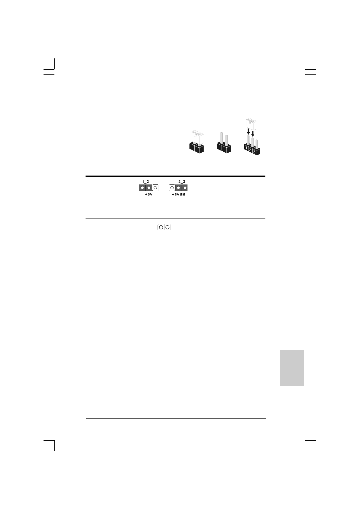
The illustration shows how jumpers are
setup. When the jumper cap is placed on
pins, the jumper is “Short”. If no jumper cap
is placed on pins, the jumper is “Open”. The
illustration shows a 3-pin jumper whose pin1
and pin2 are “Short” when jumper cap is
placed on these 2 pins.
Jumper Setting Description
PS2_USB_PWR1 Short pin2, pin3 to enable
(see p.2 No. 1) +5VSB (standby) for PS/2
Note: To select +5VSB, it requires 2 Amp and higher standby current provided by
power supply.
Clear CMOS
(CLRCMOS1, 2-pin jumper)
(see p.2 No. 6)
Note: CLRCMOS1 allows you to clear the data in CMOS. The data in CMOS includes
system setup information such as system password, date, time, and system
setup parameters. To clear and reset the system parameters to default setup,
please turn off the computer and unplug the power cord from the power
supply. After waiting for 15 seconds, use a jumper cap to short 2 pins on
CLRCMOS1 for 5 seconds.
2-pin jumper
Short Open
or USB wake up events.
ASRock ConRoe1333-DVI/H Motherboard
1717
17
1717
EnglishEnglish
EnglishEnglish
English
Page 18
2.7 Onboard Headers and Connectors2.7 Onboard Headers and Connectors
2.7 Onboard Headers and Connectors
2.7 Onboard Headers and Connectors2.7 Onboard Headers and Connectors
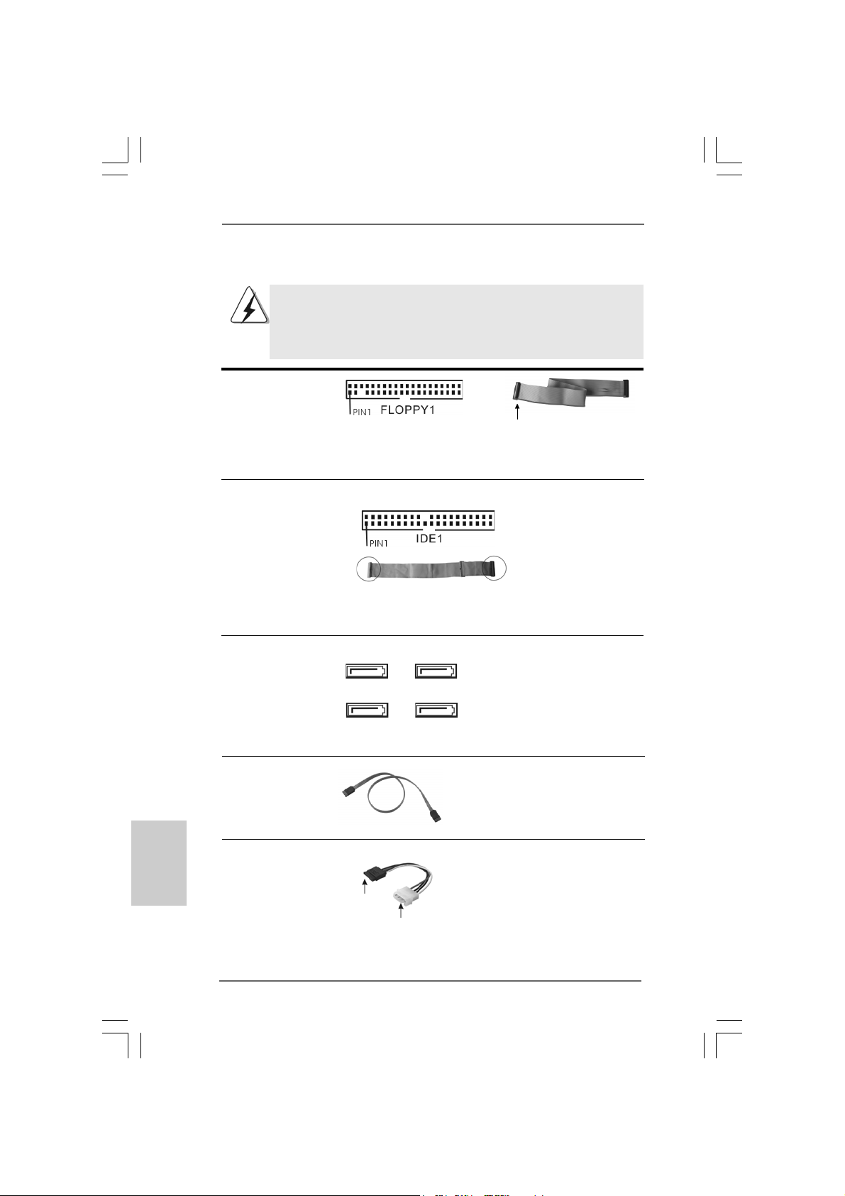
Onboard headers and connectors are NOT jumpers. Do NOT place
jumper caps over these headers and connectors. Placing jumper caps
over the headers and connectors will cause permanent damage of the
motherboard!
FDD connector
(33-pin FLOPPY1)
(see p.2 No. 20)
the red-striped side to Pin1
Note: Make sure the red-striped side of the cable is plugged into Pin1 side of the
connector.
Primary IDE connector (Blue)
(39-pin IDE1, see p.2 No. 10)
English
EnglishEnglish
EnglishEnglish
connect the blue end
to the motherboard
connect the black end
to the IDE devices
80-conductor ATA 66/100 cable
Note: Please refer to th e i n struction of your IDE device vendor for the details.
Serial A T AII Connectors These Serial AT AII (SA T AII)
(SAT AII_1: see p.2, No. 16) connectors support SATAII
(SAT AII_2: see p.2, No. 14) or SATA hard disk for internal
(SAT AII_3: see p.2, No. 15) storage devices. The current
(SAT AII_4: see p.2, No. 13) SATAII interface allows up to
SATAII_3
SATAII_1
SATAII_4
SATAII_2
3.0 Gb/s data transfer rate.
Serial A TA (SA TA) Either end of the SATA data ca ble
Data Cable can be connected to the SATA /
(Optional) SATAII hard disk or the SATAII
connector on the motherboard.
Serial ATA (SATA) Please connect the black end of
Power Cable SATA power cable to the power
(Optional) connector on each drive. Then
connect to the SAT A
HDD power connector
connect to the
power supply
connect the white end of SATA
power cable to the power
connector of the power supply.
1818
18
1818
ASRock ConRoe1333-DVI/H Motherboard
Page 19
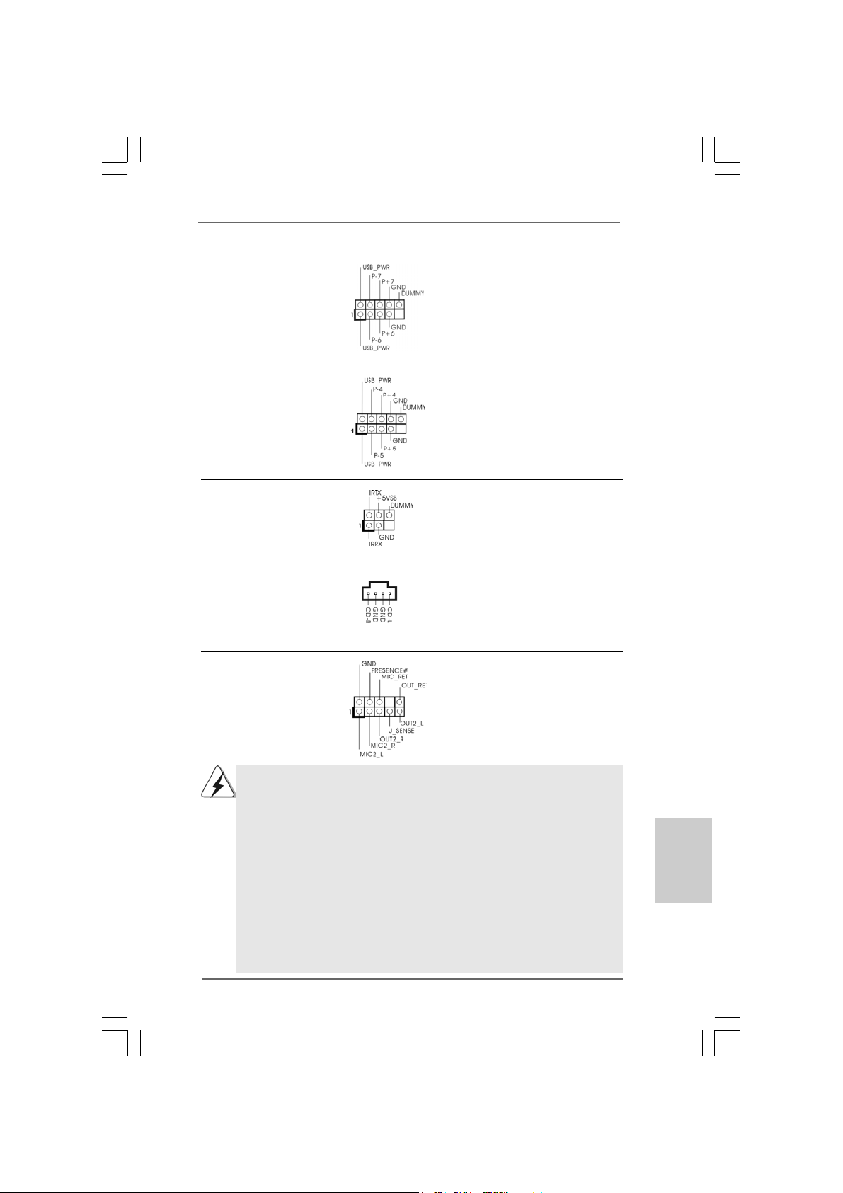
USB 2.0 Headers Besides four default USB 2.0
(9-pin USB6_7) ports on the I/O panel, there are
(see p.2 No. 18) two USB 2.0 headers on this
motherboard. Each USB 2.0
header cansupport two USB
2.0 ports.
(9-pin USB4_5)
(see p.2 No. 19)
Infrared Module Header This header supports an
(5-pin IR1) optional wireless transmitting
(see p.2 No. 30) and receiving infrared module.
Internal Audio Connector This connector allows you
(4-pin CD1) to receive stereo audio input
(CD1: see p.2 No. 24) from sound sources such as
CD1
a CD-ROM, D V D-ROM, TV
tuner card, or MPEG card.
Front Panel Audio Header This is an interface for front
(9-pin HD_AUDIO1) panel audio cable that allows
(see p.2 No. 22) convenient connection and
control of audio devices.
1. High Definition Audio supports Jack Sensing, but the panel wire on the
chassis must support HDA to function correctly. Please follow the
instruction in our manual and chassis manual to install your system.
2. If you use AC’97 audio panel, please install it to the front panel audio
header as below:
A. Connect Mic_IN (MIC) to MIC2_L.
B. Connect Audio_R (RIN) to OUT2_R and Audio_L (LIN) to OUT2_L.
C. Connect Ground (GND) to Ground (GND).
D. MIC_RET and OUT_RET are for HD audio panel only. You don’t
need to connect them for AC’97 audio panel.
E. Enter BIOS Setup Utility. Enter Advanced Settings, and then select
Chipset Configuration. Set the Front Panel Control option from
[Auto] to [Enabled].
ASRock ConRoe1333-DVI/H Motherboard
1919
19
1919
EnglishEnglish
EnglishEnglish
English
Page 20
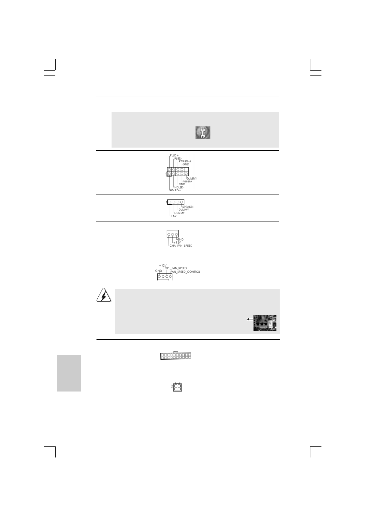
F. Enter Windows system. Click the icon on the lower right hand
taskbar to enter Realtek HD Audio Manager. Click “Audio I/O”,
select “Connector Settings” , choose “Disable front
panel jack detection”, and save the change by clicking “OK”.
System Panel Header This header accommodates
(9-pin PANEL1) several system front panel
(see p.2 No. 12) functions.
Chassis Speaker Header Please connect the chassis
(4-pin SPEAKER 1) speaker to this header.
(see p.2 No. 1 1)
Chassis Fan Connector Please connect a chassis fan
(3-pin CHA_FAN1) cable to this connector and
(see p.2 No. 17) match the black wire to the
ground pin.
CPU Fan Connector Please connect a CPU fan cable
(4-pin CPU_FAN1) to this connector and match
(see p.2 No. 3) the black wire to the ground pin.
1 2 3 4
English
EnglishEnglish
EnglishEnglish
2020
20
2020
Though this motherboard provides 4-Pin CPU fan (Quiet Fan) support, the 3-Pin
CPU fan still can work successfully even without the fan speed control function.
If you plan to connect the 3-Pin CPU fan to the CPU fan connector on this
motherboard, please connect it to Pin 1-3.
Pin 1-3 Connected
3-Pin Fan Installation
ATX Power Connector Please connect an ATX power
(20-pin ATXPW R1) supply to this connector.
(see p.2 No. 27)
ATX 12V Connector Please note that it is necessary
(4-pin A TX12V1) to connect a power supply with
(see p.2 No. 2) ATX 12V plug to this connector
so that it can provides sufficient
power. Failing to do so will cause
the failure to power up.
ASRock ConRoe1333-DVI/H Motherboard
Page 21
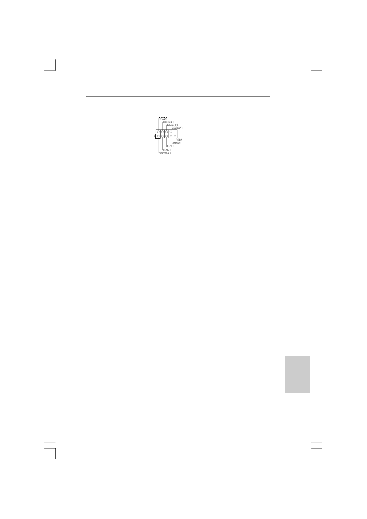
Serial port Header This COM1 header supports
(9-pin COM1) a serial port module.
(see p.2 No. 29)
ASRock ConRoe1333-DVI/H Motherboard
2121
21
2121
EnglishEnglish
EnglishEnglish
English
Page 22
2.82.8
SASA
TT
2.8
2.82.8
Before installing SATAII hard disk to your computer, please carefully read below
SATAII hard disk setup guide. Some default setting of SATAII hard disks may not
be at SATAII mode, which operate with the best performance. In order to enable
SATAII function, please follow the below instruction with different vendors to
correctly adjust your SATAII hard disk to SATAII mode in advance; otherwise, your
SATAII hard disk may fail to run at SATAII mode.
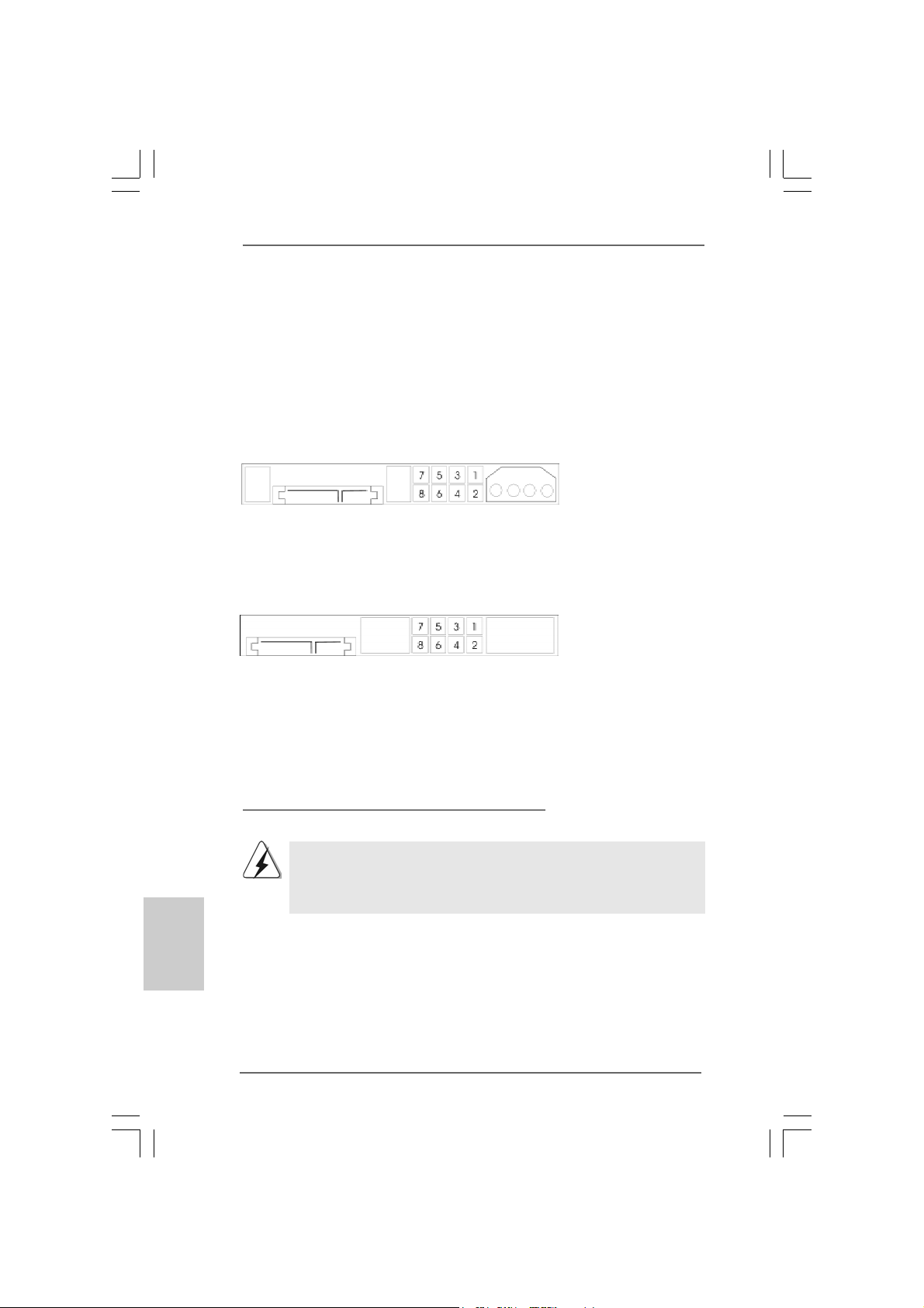
Western Digital
If pin 5 and pin 6 are shorted, SATA 1.5Gb/s will be enabled.
On the other hand, if you want to enable SATAII 3.0Gb/s, please remove the
jumpers from pin 5 and pin 6.
SAMSUNG
If pin 3 and pin 4 are shorted, SATA 1.5Gb/s will be enabled.
On the other hand, if you want to enable SATAII 3.0Gb/s, please remove the
jumpers from pin 3 and pin 4.
AII Hard Disk Setup GuideAII Hard Disk Setup Guide
SA
T
AII Hard Disk Setup Guide
SASA
TT
AII Hard Disk Setup GuideAII Hard Disk Setup Guide
English
EnglishEnglish
EnglishEnglish
2222
22
2222
HITACHI
Please use the Feature Tool, a DOS-bootable tool, for changing various ATA
features. Please visit HITACHI’s website for details:
http://www.hitachigst.com/hdd/support/download.htm
The above examples are just for your reference. For different SATAII hard
disk products of different vendors, the jumper pin setting methods may not
be the same. Please visit the vendors’ website for the updates.
ASRock ConRoe1333-DVI/H Motherboard
Page 23
2.92.9
Serial ASerial A
2.9
Serial A
2.92.9
Serial ASerial A
Installation Installation
Installation
Installation Installation
This motherboard adopts Intel® ICH7 south bridge chipset that supports Serial ATA
(SATA) / Serial ATAII (SATAII) hard disks. You may install SATA / SATAII hard disks
on this motherboard for internal storage devices. This section will guide you to
install the SATA / SATAII hard disks.
STEP 1: Install the SATA / SATAII hard disks into the drive bays of your chassis.
STEP 2: Connect the SATA power cable to the SATA / SATAII hard disk.
STEP 3: Connect one end of the SATA data cable to the motherboard’s SATAII
connector.
STEP 4: Connect the other end of the SATA data cable to the SATA / SATAII hard
disk.
2.102.10
Driver Installation GuideDriver Installation Guide
2.10
Driver Installation Guide
2.102.10
Driver Installation GuideDriver Installation Guide
To install the drivers to your system, please insert the support CD to your optical
drive first. Then, the drivers compatible to your system can be auto-detected and
listed on the support CD driver page. Please follow the order from up to bottom
side to install those required drivers. Therefore, the drivers you install can work
properly.
2.112.11
HDMR Card and Driver Installation HDMR Card and Driver Installation
2.11
HDMR Card and Driver Installation
2.112.11
HDMR Card and Driver Installation HDMR Card and Driver Installation
If you do not insert HDMR card to this motherboard, and you finish installing all
drivers to your system now, but in the future, you plan to use HDMR card function
on this motherboard, please follow the steps below then.
1. Insert HDMR card to HDMR slot on this motherboard. Please make sure that the
HDMR card is completely seated on the slot.
2. Install HDMR card driver from our support CD to your system.
3. Reboot your system.
TT
A (SAA (SA
T
A (SA
TT
A (SAA (SA
TT
A) / Serial AA) / Serial A
T
A) / Serial A
TT
A) / Serial AA) / Serial A
TT
AII (SAAII (SA
T
AII (SA
TT
AII (SAAII (SA
TT
AII) Hard DisksAII) Hard Disks
T
AII) Hard Disks
TT
AII) Hard DisksAII) Hard Disks
2.122.12
Untied Overclocking TUntied Overclocking T
2.12
Untied Overclocking T
2.122.12
Untied Overclocking TUntied Overclocking T
This motherboard supports Untied Overclocking Technology, which means during
overclocking, FSB enjoys better margin due to fixed PCI / PCIE buses. Before you
enable Untied Overclocking function, please enter “Overclock Mode” option of BIOS
setup to set the selection from [Auto] to [CPU, PCIE, Async.]. Therefore, CPU FSB is
untied during overclocking, but PCI / PCIE buses are in the fixed mode so that FSB can
operate under a more stable overclocking environment.
Please refer to the warning on page 6 for the possible overclocking risk before
you apply Untied Overclocking Technology.
ASRock ConRoe1333-DVI/H Motherboard
echnologyechnology
echnology
echnologyechnology
2323
23
2323
EnglishEnglish
EnglishEnglish
English
Page 24
3. BIOS Information3. BIOS Information
3. BIOS Information
3. BIOS Information3. BIOS Information
The Flash Memory on the motherboard stores BIOS Setup Utility. When you start up
the computer, please press <F2> during the Power-On-Self-Test (POST) to enter
BIOS Setup utility; otherwise, POST continues with its test routines. If you wish to
enter BIOS Setup after POST, please restart the system by pressing <Ctl> + <Alt> +
<Delete>, or pressing the reset button on the system chassis.
The BIOS Setup program is designed to be user-friendly. It is a menu-driven program,
which allows you to scroll through its various sub-menus and to select among the
predetermined choices. For the detailed information about BIOS Setup, please refer
to the User Manual (PDF file) contained in the Support CD.
English
EnglishEnglish
EnglishEnglish
4. Software Suppor4. Software Suppor
4. Software Suppor
4. Software Suppor4. Software Suppor
This motherboard supports various Microsoft® Windows® operating systems: 2000 /
XP / XP 64-bit / VistaTM / Vista
contains necessary drivers and useful utilities that will enhance motherboard features.
To begin using the Support CD, insert the CD into your CD-ROM drive. It will display
the Main Menu automatically if “AUTORUN” is enabled in your computer. If the Main
Menu does not appear automatically, locate and double-click on the file “ASSETUP.
EXE” from the BIN folder in the Support CD to display the menus.
TM
64-bit. The Support CD that ca me with the motherboard
t CD informationt CD information
t CD information
t CD informationt CD information
2424
24
2424
ASRock ConRoe1333-DVI/H Motherboard
Page 25
ASRock ConRoe1333-DVI/H Motherboard
2525
25
2525
Page 26
®
® ® ®
®
®
®
2626
26
2626
®
ASRock ConRoe1333-DVI/H Motherboard
Page 27
®
®
ASRock ConRoe1333-DVI/H Motherboard
2727
27
2727
Page 28
®
®
®
®
®
®
®
2828
28
2828
®
®
®
®
ASRock ConRoe1333-DVI/H Motherboard
Page 29
®
®
®
®
®
®
®
ASRock ConRoe1333-DVI/H Motherboard
2929
29
2929
Page 30
3030
30
3030
ASRock ConRoe1333-DVI/H Motherboard
Page 31

ASRock ConRoe1333-DVI/H Motherboard
3131
31
3131
Page 32

3232
32
3232
ASRock ConRoe1333-DVI/H Motherboard
Page 33

DDRII_1 DDRII_2 DDRII_3 DDRII_4
( )( )( )( )
(1) - (2) - (3)
ASRock ConRoe1333-DVI/H Motherboard
3333
33
3333
Page 34

3434
34
3434
ASRock ConRoe1333-DVI/H Motherboard
Page 35

ASRock ConRoe1333-DVI/H Motherboard
3535
35
3535
Page 36

3636
36
3636
ASRock ConRoe1333-DVI/H Motherboard
Page 37

®
®
®
®
ASRock ConRoe1333-DVI/H Motherboard
3737
37
3737
Page 38

3838
38
3838
ASRock ConRoe1333-DVI/H Motherboard
Page 39

SATAII_3
SATAII_4
SATAII_1
SATAII_2
ASRock ConRoe1333-DVI/H Motherboard
3939
39
3939
Page 40

4040
40
4040
CD1
ASRock ConRoe1333-DVI/H Motherboard
Page 41

1 2 3 4
ASRock ConRoe1333-DVI/H Motherboard
4141
41
4141
Page 42

4242
42
4242
ASRock ConRoe1333-DVI/H Motherboard
Page 43

®
ASRock ConRoe1333-DVI/H Motherboard
4343
43
4343
Page 44

® ®
4444
44
4444
ASRock ConRoe1333-DVI/H Motherboard
Page 45

O:
X:
X O O O O O
X O O O O O
ASRock ConRoe1333-DVI/H Motherboard
4545
45
4545
Page 46

1. Einführung1. Einführung
1. Einführung
1. Einführung1. Einführung
Wir danken Ihnen für den Kauf des ASRock ConRoe1333-DVI/H Motherboard, ein
zuverlässiges Produkt, welches unter den ständigen, strengen Qualitätskontrollen
von ASRock gefertigt wurde. Es bietet Ihnen exzellente Leistung und robuste s Design,
gemäß der Verpflichtung von ASRock zu Qualität und Halbarkeit.
Diese Schnellinstallationsanleitung führt in das Motherboard und die schrittweise
Installation ein. Details über das Motherboard finden Sie in der
Bedienungsanleitung auf der Support-CD.
Da sich Motherboard-Spezifikationen und BIOS-Software verändern können,
kann der Inhalt dieses Handbuches ebenfalls jederzeit geändert werden. Für
den Fall, dass sich Änderungen an diesem Handbuch ergeben, wird eine neue
Version auf der ASRock-Website, ohne weitere Ankündigung, verfügbar sein.
Die neuesten Grafikkarten und unterstützten CPUs sind auch auf der
ASRock-Website aufgelistet.
ASRock-Website: http://www.asrock.com
1.1 Kartoninhalt
ASRock ConRoe1333-DVI/H Motherboard
(Micro ATX-Formfaktor: 24.4 cm x 24.4 cm; 9.6 Zoll x 9.6 Zoll)
ASRock ConRoe1333-DVI/H Schnellinstallationsanleitung
ASRock ConRoe1333-DVI/H_ Support-CD
Ein 80-adriges Ultra-ATA 66/100 IDE-Flachbandkabel
Ein Flachbandkabel für ein 3,5-Zoll-Diskettenlaufwerk
Ein Seriell-ATA- (SATA) Datenkabel (Option)
Ein Seriell-ATA (SATA) Festplattennetzkabel (Option)
Ein HD 8CH I/O Shield
Ein COM Port-Anschlusshalter
Eine DVI Gra phics-HDCP-Karte
Deutsch
DeutschDeutsch
DeutschDeutsch
4646
46
4646
ASRock ConRoe1333-DVI/H Motherboard
Page 47

1.21.2
SpezifikationenSpezifikationen
1.2
Spezifikationen
1.21.2
SpezifikationenSpezifikationen
Plattform - Micro ATX-Formfaktor: 24.4 cm x 24.4 cm; 9.6 Zoll x 9.6 Zoll
CPU - LGA 775 für Intel® Dual Core CoreTM 2 Extreme- / CoreTM 2
Duo- / Pentium® D- / Pentium® 4- / Celeron® D-Prozessoren
- Kompatibilität mit allen Zentraleinheiten (CPU) FSB1333/1066/
800/533MHz außer Quadrangel Kerne (siehe VORSICHT 1)
- Unterstützt Hyper-Threading-Technologie
(siehe VORSICHT 2)
- Unterstützt Untied-Übertaktungstechnologie
(siehe VORSICHT 3)
- Unterstützt EM64T -CPU
Chipsatz - Northbridge: Intel® 945G
- Southbridge: Intel® ICH7
Speicher - Unterstützung von Dual-Kanal-DDRII-Speichertechnologie
(siehe VORSICHT 4)
- 4 x Steckplätze für DDRII
- Unterstützt DDRII667/533 (siehe VORSICHT 5)
- Max. 4GB (siehe VORSICHT 6)
Hybrid Booster - Schrittloser CPU-Frequenz-Kontrolle (siehe VORSICHT 7)
- ASRock U-COP (siehe VORSICHT 8)
- Boot Failure Guard (B.F.G. – Systemstartfehlerschutz)
Erweiterungs- - 1 x PCI Express x16-Steckplätze
steckplätze - 1 x PCI Express x1-Steckplätze
- 2 x PCI -Steckplätze
- 1 x HDMR-Steckplätze
Onboard-VGA - Intel® Graphics Media Accelerator 950
- Pixel Shader 2.0, DX9.0 VGA
- Maximal gemeinsam genutzter Speicher 224MB
(siehe VORSICHT 9)
- Doppel VGA Ausgang¡GDVI-D und D-Sub- Anschluß sind mit
DVI Graphiken–HDCP Karte durch unabhängige
Anzeigekontroller zu unterstützen
- HDCP Funktion ist mit D VI Graphik s-HDCP Karte zu unterstützen
Audio - 7.1 CH Windows® VistaTM Premium Level HD Audio
(ALC888 Audio Codec)
LAN - PCIE x1 Giga bit LAN 10/100/1000 Mb/s
- Realtek RTL8111B
- Unterstützt Wake-On-LAN
E/A-Anschlüsse HD 8CH I/O
an der - 1 x PS/2-Mausanschluss
Rückseite - 1 x PS/2-Tastaturanschluss
ASRock ConRoe1333-DVI/H Motherboard
4747
47
4747
DeutschDeutsch
DeutschDeutsch
Deutsch
Page 48

Deutsch
DeutschDeutsch
DeutschDeutsch
- 1 x VGA port
- 1 x Paralleler port: Unterstützung für ECP / EPP
- 4 x Standard-USB 2.0-Anschlüsse
- 1 x RJ-45 port
- HD Audiobuchse: Lautsprecher seitlich / Lautsprecher hinten
/ Mitte/Bass / Audioeingang/ Lautsprecher vorne / Mikrofon
(siehe VORSICHT 10)
Anschlüsse - 4 x SATAII-Anschlüsse, unterstützt bis 3.0 Gb/s
Datenübertragungsrate (Unterstützt keine “RAID”- und “Hot Plug”-Funktionen) (siehe VORSICHT 11)
- 1 x ATA100 IDE-Anschlüsse (Unterstützt bis 2 IDE-Geräte)
- 1 x FDD-Anschlüsse
- 1 x Infrarot-Modul-Header
- 1 x COM-Anschluss-Header
- CPU/Gehäuse-Lüfteranschluss
- 20-pin ATX-Netz-Header
- 4-pin anschluss für 12V-ATX-Netzteil
- Interne Audio-Anschlüsse
- Anschluss für Audio auf der Gehäusevorderseite
- 2 x USB 2.0-Anschlüsse (Unterstützung 4
zusätzlicher USB 2.0-Anschlüsse) (siehe VORSICHT 12)
BIOS - 4Mb AMI BIOS
- AMI legal BIOS mit Unterstützung für “Plug and Play”
- ACPI 1.1-Weckfunktionen
- JumperFree-Modus
- SMBIOS 2.3.1
Support-CD - Treiber , Dien stprogramme, Antivirussoftware
(Probeversion)
Hardware Monitor - Überwachung der CPU-Temperatur
- Motherboardtemperaturerkennung
- Drehzahlmessung für CPU-Lüfter
- Drehzahlmessung für Gehäuselüfter
- CPU-Lüftergeräuschdämpfung
- Spannungsüberwachung: +12V, +5V, +3.3V, Vcore
Betriebssysteme - Unterstützt Microsoft® Windows® 2000 / XP / XP 64-Bit /
VistaTM / Vista
Zertifizierungen - FCC, CE, WHQL
TM
64-Bit (siehe VORSICHT 13)
4848
48
4848
ASRock ConRoe1333-DVI/H Motherboard
Page 49

WARNUNG
Beachten Sie bitte, dass Overclocking, einschließlich der Einstellung im BIOS, Anwenden
der Untied Overclocking-Technologie oder Verwenden von Overclocking-Werkzeugen von
Dritten, mit einem gewissen Risiko behaftet ist. Overclocking kann sich nachteilig auf die
Stabilität Ihres Systems auswirken oder sogar Komponenten und Geräte Ihres Systems
beschädigen. Es geschieht dann auf eigene Gefahr und auf Ihre Kosten. Wir übernehmen
keine Verantwortung für mögliche Schäden, die aufgrund von Overclocking verursacht
wurden.
VORSICHT!
1. FSB1333-CPU wird nach Uhrzeitmode operatieren. In diese Situation
wird PCIE Frequenz auch nach Uhrzeitmode zu 115MHz.
2. Die Einstellung der “Hyper-Threading Technology”, finden Sie auf Seite
31 des auf der Support-CD enthaltenen Benutzerhandbuches
beschrieben.
3. Dieses Motherboard unterstützt die Untied-Übertaktungstechnologie.
Unter “Entkoppelte Übertaktungstechnologie” auf Seite 67 finden Sie
detaillierte Informationen.
4. Dieses Motherboard unterstützt Dual-Kanal-Speichertechnologie. Vor
Implementierung der Dual-Kanal-Speichertechnologie müssen Sie die
Installationsanleitung für die Speichermodule auf Seite 55 zwecks
richtiger Installation gelesen haben.
5. Die unterstützten Arbeitsspeicherfrequenzen und die entsprechende
CPU FSB-Frequenz entnehmen Sie bitte der nachstehenden Tabelle.
CPU FSB-Frequenz Unterstützte Arbeitsspeicherfrequenz
1333 DDRII533*, DDRII667
1066 DDRII400, DDRII533, DDRII667
800 DDRII400, DDRII533, DDRII667
533 DDRII400, DDRII533
* Bei Verwendung einer FSB1333-CPU auf diesem Motherboard läuft es
mit DDRII500, wenn Sie ein DDRII533-Speichermodul verwenden.
6. Aufgrund von Chipset-Einschränkungen könnte unter Windows
Windows® XP, Windows® XP 64-Bit, Windows® VistaTM und Windows
TM
Vista
64-Bit die für das System reservierte Speichergröße unterhalb
von 4 GB liegen.
7. Obwohl dieses Motherboard stufenlose Steuerung bietet, wird Overclocking nicht empfohlen. Frequenzen, die über den für den jeweiligen
Prozessor vorgesehenen liegen, können das System instabil werden
lassen oder die CPU beschädigen.
8. Wird eine Überhitzung der CPU registriert, führt das System einen
automatischen Shutdown durch. Bevor Sie das System neu starten, prüfen
Sie bitte, ob der CPU-Lüfter am Motherboard richtig funktioniert, und
stecken Sie bitte den Stromkabelstecker aus und dann wieder ein. Um die
Wärmeableitung zu verbessern, bitte nicht vergessen, etwa s Wärmeleitpa ste
zwischen CPU und Kühlkörper zu sprühen.
9. Die Maximalspeichergröße ist von den Chipshändler definiert und
umgetauscht. Bitte überprüfen Sie Intel® website für die neuliche
Information.
ASRock ConRoe1333-DVI/H Motherboard
®
2000,
®
4949
49
4949
DeutschDeutsch
DeutschDeutsch
Deutsch
Page 50

10. Der Mikrofoneingang dieses Motherboards unterstützt Stereo- und MonoModi. Der Audioausgang dieses Motherboards unterstützt 2-Kanal-, 4-Kanal-,
6-Kanal- und 8-Kanal-Modi. Stellen Sie die richtige Verbindung anhand der
Tabelle auf Seite 3 her.
11. Bevor Sie eine SATA II Festplatte mit dem SATA II Anschluss verbinden,
lesen Sie bitte die “Anleitung zur SATA II Festplatteneinrichtung“ auf
Seite 65, um Ihre SATA II Festplatte in den SATA II Modus umzuschalten.
SATA-Festplatten können Sie auch direkt mit dem SATA II-Anschluss
verbinden.
12. Das Power Management für USB 2.0 arbeitet unter Microsoft® Windows
VistaTM 64-Bit / VistaTM / XP 64-Bit / XP SP1 oder SP2/2000 SP4
einwandfrei.
13. Der Microsoft® Windows® VistaTM / VistaTM 64-Bit Treiber wird ständig
aktualisiert. Sobald wir den neuesten Treiber haben, stellen wir ihn auf
unserer Website zur V erfügung. Bitte besuchen Sie unsere Website für
den Microsoft® Windows® VistaTM / VistaTM 64-Bit Treiber und verwandte
Informationen.
ASRock-Website http://www.asrock.com
®
Deutsch
DeutschDeutsch
DeutschDeutsch
5050
50
5050
1.31.3
Minimale Hardwarevorausetzungen für WindowsMinimale Hardwarevorausetzungen für Windows
1.3
Minimale Hardwarevorausetzungen für Windows
1.31.3
Minimale Hardwarevorausetzungen für WindowsMinimale Hardwarevorausetzungen für Windows
TMTM
TM
TMTM
VistaVista
Vista
VistaVista
Premium 2007 und Basic Logo Premium 2007 und Basic Logo
Premium 2007 und Basic Logo
Premium 2007 und Basic Logo Premium 2007 und Basic Logo
Systemintegratoren und Anwender unseres Motherboards, die ihre
Rechner auf die Vergabe des Windows® VistaTM Premium 2007 und Basic Logos vorbereiten möchten, finden die minimalen
hardwarevoraussetzungen in der folgenden Tabelle.
CPU Celeron D 326
Speicher 512 MB x 2 Dual Channel (Premium)
512 MB Single Channel (Ba sic)
256 MB x 2 Dual Channel (Basic)
VGA DX9.0 mit WDDM-Treiber
DVI mit HDCP
* Wenn Sie eine integrierte VGA-Karte mit einem Gesamtsystemspeicher von 512 MB
verwenden und vorhaben, das Windows® VistaTM Basic-Logo zu verwenden, stellen
Sie bitte den gemeinsam genutzten Speicher der integrierten VGA-Karte auf 64 MB.
Falls Sie eine integrierte VGA-Karte mit einem Gesamtsystemspeicher von mehr
als 512 MB verwenden und vorhaben, das Windows® VistaTM Premium und Basic Logo zu verwenden, kann der gemeinsam genutzte Speicher der integrierten VGA Karte auf bis zu 128 MB eingestellt werden.
* Sofern Sie eine externe Grafikkarte mit diesem Motherboard verwenden möchten,
lesen Sie bitte unter Premium Discrete-Anforderungen auf unseren Internetseiten
nach: http://www.asrock.com
* Wenn VGA auf der Platte DVI unterstützt, muß es auch HDCP Function
unterstützen,um Windows® VistaTM Premium 2007 logo.zu befähigen.
* Nach dem ersten Juni, 2007 sind , all Windows® VistaTM Systems dafür erforderlich,
mit der Minimalforderung der obengenannte Hardware übereinzustimmen, um
Windows® VistaTM Premium 2007 logo.zu befähigen.
ASRock ConRoe1333-DVI/H Motherboard
®
Page 51

2. Installation2. Installation
2. Installation
2. Installation2. Installation
Sicherheitshinweise vor der MontageSicherheitshinweise vor der Montage
Sicherheitshinweise vor der Montage
Sicherheitshinweise vor der MontageSicherheitshinweise vor der Montage
Bitte nehmen Sie die folgende Sicherheitshinweise zur Kenntnis, bevor Sie das
Motherboard einbauen oder Veränderungen an den Einstellungen vornehmen.
1. Trennen Sie das System vom Stromnetz, bevor Sie eine ystemkomponente
berühren, da es sonst zu schweren Schäden a m Motherboard oder den
sonstigen internen, bzw. externen omponenten kommen kann.
2. Um Schäden aufgrund von statischer Elektrizität zu vermeiden, das
Motherboard NIEMALS auf einen Teppich o.ä.legen. Denken Sie außerem
daran, immer ein geerdetes Armband zu tragen oder ein geerdetes Objekt
aus Metall zu berühren, bevor Sie mit Systemkomponenten hantieren.
3. Halten Sie Komponenten immer an den Rändern und vermeiden Sie
Berührungen mit den ICs.
4. Wenn Sie Komponenten ausbauen, legen Sie sie immer auf eine
antistatische Unterlage, oder zurück in die Tüte, mit der die Komponente
geliefert wurde.
5. Wenn Sie das Motherboard mit den Schrauben an dem Computergehäuse
befestigen, überziehen Sie bitte die Schrauben nicht! Das Motherboard kann
sonst beschädigt werden.
2.1 CPU Installation2.1 CPU Installation
2.1 CPU Installation
2.1 CPU Installation2.1 CPU Installation
Für die Installation des Intel 775-Pin CPU
führen Sie bitte die folgenden Schritte durch.
Bevor Sie die 775-Pin CPU in den Sockel sitzen, prüfen Sie bitte,
ob die CPU-Oberfläche sauber ist und keine der Kontakte verbogen
sind. Setzen Sie die CPU nicht mit Gewalt in den Sockel, dies kann
die CPU schwer beschädigen.
ASRock ConRoe1333-DVI/H Motherboard
(Ladeplatte)
(Kontaktreihe)
775-Pin Sockel Übersicht
(Sockel)
5151
51
5151
DeutschDeutsch
DeutschDeutsch
Deutsch
Page 52

Schritt 1. Öffnen Sie den Sockel:
Schritt 1-1. Öffnen Sie den Hebel, indem
Sie ihn nach unten drücken und
aushaken.
Schritt 1-2. Drehen Sie den Ladehebel, bis
er in geöffneter Position steht,
ca. 135 Grad.
Schritt 1-3. Drehen Sie die Ladeplatte, bis
sie in geöffneter Position steht,
ca. 100 Grad.
Schritt 2. 775-Pin CPU einstecken:
Schritt 2-1. Halten Sie die CPU an den mit
schwarzen Linien
gekennzeichneten Seiten.
Schritt 2-2. Halten Sie das Teil mit dem IHS
(Integrated Heat Sink –
integrierter Kühlkörper) nach
oben. Suchen Sie Pin 1 und die
zwei
Orientierungseinkerbungen.
Pin1
Orientierungskerbe
Ausrichtungsmarkierung
Orientierungskerbe
Pin1
Schwarze Linie
775-Pin Sockel
Schwarze Linie
Ausrichtungsmarkierung
Deutsch
DeutschDeutsch
DeutschDeutsch
5252
52
5252
775-Pin CPU
Um die CPU ordnungsgemäß einsetzen zu können, richten Sie die
zwei Orientierungskerben der CPU mit den beiden Markierungen des
Sockels aus.
Schritt 2-3. Drücken Sie die CPU vorsichtig
in vertikaler Richtung in den
Sockel.
ASRock ConRoe1333-DVI/H Motherboard
Page 53

Schritt 2-4. Prüfen Sie, dass die CPU
ordnungsgemäß im Sockel sitzt
und die Orientierungskerben
einwandfrei in den
entsprechenden Auskerbungen
sitzen.
Schritt 3. PnP-Kappe entfernen (Pick and Place-Kappe):
Halten Sie den Rand der Ladeplatte mit
Zeigefinger und Daumen Ihrer linken Hand,
halten Sie die PnP-Kappe mit dem Daumen
der rechten Hand und ziehen Sie die Kappe
vom Sockel während Sie auf die Mitte der
Kappe drücken, um ein Entfernen zu
erleichtern.
1. Verwenden Sie beim Entfernen die Kappenlasche und vermeiden
Sie ein Abreißen der PnP-Kappe.
2. Diese Kappe muss angebracht werden, falls Sie das Motherboard
zur Reparatur bringen.
Schritt 4. Sockel schließen:
Schritt 4-1. Drehen Sie die Ladeplatte auf
den Kühlkörper (IHS).
Schritt 4-2. Drücken Sie leicht auf die
Ladeplatte und schließen Sie
den Ladehebel.
Schritt 4-3. Sichern Sie Ladehebel und
Ladeplatte mithilfe des
Hebelverschlusses.
ASRock ConRoe1333-DVI/H Motherboard
5353
53
5353
DeutschDeutsch
DeutschDeutsch
Deutsch
Page 54

2.22.2
Installation des CPU-Lüfters und KühlkörpersInstallation des CPU-Lüfters und Kühlkörpers
2.2
Installation des CPU-Lüfters und Kühlkörpers
2.22.2
Installation des CPU-Lüfters und KühlkörpersInstallation des CPU-Lüfters und Kühlkörpers
Für Installationshinweise, siehe Betriebsanleitung Ihres CPU-Lüfters und
Kühlkörpers.
Unten stehend ein Beispiel zur Installation eines Kühlkörpers für den 775-Pin CPU.
Deutsch
DeutschDeutsch
DeutschDeutsch
Schritt 1. Geben Sie Wärmeleitmaterial auf die Mitte
des IHS, auf die Sockeloberfläche.
Schritt 2. Setzen Sie den Kühlkörper auf den Sockel.
Prüfen Sie, dass die Lüfterkabel auf der
Seite am nächsten zum CPU-LüfterAnschluss des Motherboards verlaufen
(CPU_FAN1, siehe Seite 2, Nr. 3).
Schritt 3. Richten Sie Verbindungselemente und
Löcher im Motherboard aus.
Schritt 4. Drehen Sie die Verbindungselemente im
Uhrzeigersinn und drücken Sie mit dem
Daumen auf die Kappen der Elemente zum
Feststellen. Wiederholen Sie dies mit den
anderen Verbindungselementen.
Wenn Sie die Verbindungselemente nur drücken, ohne sie im
Uhrzeigersinn zu drehen, wird der Kühlkörper nicht ordnungsgemäß
am Motherboard befestigt.
Schritt 5. Schließen Sie den Lüfter an den CPU-
Lüfteranschluss des Motherboards.
Schritt 6. Befestigen Sie überschüssiges Kabel mit
Band, um eine Störung des Lüfters oder
Kontakt mit anderen Teilen zu vermeiden.
(Tragen Sie Wärmeleitmaterial auf. )
(Lüfterkabel auf der Seite am nächsten
zum Anschluss des Motherboards)
(Schlitze der Verbindungselemente
nach außen)
(Nach unten drücken (4 Stellen))
5454
54
5454
ASRock ConRoe1333-DVI/H Motherboard
Page 55

2.3 Installation der Speichermodule (DIMM)2.3 Installation der Speichermodule (DIMM)
2.3 Installation der Speichermodule (DIMM)
2.3 Installation der Speichermodule (DIMM)2.3 Installation der Speichermodule (DIMM)
Die Motherboards ConRoe1333-DVI/H bieten vier 240-pol. DDRII (Double Data
Rate II) DIMM-Steckplätze und unterstützen die Dual-Kanal-Speichertechnologie.
Für die Dual-Kanalkonfiguration dürfen Sie nur identische (gleiche Marke,
Geschwindigkeit, Größe und gle icher Chi ptyp) DDRII DIMM-Paare in den
Steckplätzen gleicher Farbe installieren. Mit anderen Worten, sie müssen ein
identisches DDR DIMM-Paar im Dual-Kanal A (DDRII_1 und DDRII_3; gelbe
Steckplätze, siehe Seite 2 Nr. 7) oder ein identisches DDRII DIMM-Paar im DualKanal B (DDRII_2 und DDRII_4; orange Steck plätze, siehe Se ite 2 Nr. 8) installieren,
damit die Dual-Kanal-Speichertechnologie aktiviert werden kann. Auf diesem
Motherboard können Sie auch vier DDRII DIMMs für eine Dual-Kanalkonfiguration
installieren. Auf diesem Motherboard können Sie auch vier DDRII DIMM-Module für
eine Dual-Kanalkonfiguration installieren, wobei Sie bitte in allen vier Steckplätzen
identische DDRII DIMM-Module installieren. Beziehen Sie sich dabei auf die
nachstehende Konfigurationstabelle für Dual-Kanalspeicher.
Dual-Kanal-Speicherkonfigurationen
DDRII_1 DDRII_2 DDRII_3 DDRII_4
(gelbe Steckplätze) (orange Steckplätze) (gelbe Steckplätze) (orange Steckplätze)
(1) Bestückt - Bestückt (2) - Bestückt - Bestückt
(3) Bestückt Bestückt Bestückt Bestückt
* Für Konfiguration (3) installieren Sie bitte identische DDRII DIMMs in allen vier
Steckplätzen.
1. Wenn Sie zwei Speichermodule installieren möchten, verwenden Sie
dazu für optimale Kompatibilität und Stabilität Steckplätze gleicher
Farbe. Installieren Sie die beiden Speichermodule also entweder in
den gelbe Steckplätzen (DDRII_1 und DDRII_3) oder den orange
Steckplätzen (DDRII_2 und DDRII_4).
2. Wenn nur ein Speichermodul oder drei Speichermodule in den DDRII
DIMM-Steckplätzen auf diesem Motherboard installiert sind, kann es
die Dual-Kanal-Speichertechnologie nicht aktivieren.
3. Ist ein Speichermodulpaar NICHT im gleichen “Dual-Kanal” installiert,
z.B. ein Speichermodulpaar wird in DDRII_1 und DDRII_2 installiert,
kann es die Dual-Kanal-Speichertechnologie nicht aktivieren.
4. Es ist nicht zulässig, DDR in einen DDRII Steckplatz zu installieren;
andernfalls könnten Motherboard und DIMMs beschädigt werden.
ASRock ConRoe1333-DVI/H Motherboard
5555
55
5555
DeutschDeutsch
DeutschDeutsch
Deutsch
Page 56

Einsetzen eines DIMM-Moduls
Achten Sie darauf, das Netzteil abzustecken, bevor Sie DIMMs oder
Systemkomponenten hinzufügen oder entfernen.
Schritt 1: Öffnen Sie einen DIMM-Slot, indem Sie die seitlichen Clips nach außen
drücken.
Schritt 2: Richten Sie das DIMM-Modul so über dem Slot aus, dass das Modul mit
der Kerbe in den Slot passt.
Deutsch
DeutschDeutsch
DeutschDeutsch
5656
56
5656
Die DIMM-Module passen nur richtig herum eingelegt in die
Steckplätze. Falls Sie versuchen, die DIMM-Module mit Gewalt falsch
herum in die Steckplätze zu zwingen, führt dies zu dauerhaften
Schäden am Mainboard und am DIMM-Modul.
Schritt 3: Drücken Sie die DIMM-Module fest in die Steckplätze, so dass die
Halteklammern an beiden Enden des Moduls einschnappen und das
DIMM-Modul fest an Ort und Stelle sitzt.
ASRock ConRoe1333-DVI/H Motherboard
Page 57

2.4 Erweiterungssteckplätze: (PCI-, HDMR- und PCI2.4 Erweiterungssteckplätze: (PCI-, HDMR- und PCI
2.4 Erweiterungssteckplätze: (PCI-, HDMR- und PCI
2.4 Erweiterungssteckplätze: (PCI-, HDMR- und PCI2.4 Erweiterungssteckplätze: (PCI-, HDMR- und PCI
Express-Slots): Express-Slots):
Express-Slots):
Express-Slots): Express-Slots):
Es stehen 2 PCI-, 1 HDMR- und 2 PCI Express-Slot auf dem ConRoe1333-DVI/H
Motherboard zur Verfügung.
PCI-Slots: PCI-Slots werden zur Installation von Erweiterungskarten mit dem
32bit PCI-Interface genutzt.
HDMR-Slot: Der HDMR-Steckplatz dient zur Aufnahme der HDMR-Karte mit v.92
Modem-Funktionalität. Der HDM R-Ste ckplatz te ilt sich die
Verwendung mit dem PCI2-Steckplatz.
PCI Express-Slots: PCIE1 (PCIE x16-Steckplatz) wird für PCI Express-Karten mit
x16 Lane Width-Grafikkarten oder einer ASRock DVI
Graphics-HDCP-Karte verwendet.
PCIE2 (PCIE x1-Steckplatz) wird für PCI Express Grafikkarten mit x1-Busbreite verwendet wie Gigabit LAN Karten, SATA2-Karten, usw. eingesetzt.
1. Wenn Sie die zusätzliche PCI Express-VGA-Karte in PCIE1 (PCIE x16-
Steckplatz) installieren, wird das integrierte VGA deaktiviert. Installieren Sie
die zusätzliche PCI Express-VGA-Karte in PCIE1 (PCIE x16-Steckplatz) und
setzen Sie die BIOS-Option “Internal Graphics Mode Select” (Wahl des
internen Grafikmodus) auf [Enabled] (Aktiviert), wird das integrierte VGA
aktiviert und der primäre Bildschirm ist das integrierte VGA.
2. Sie können nur eine PCI Express-VGA-Karte oder eine DVI Graphics-HDCP-
Karte in PCIE1 (PCIE x16-Steckplatz) installieren.
Einbau einer ErweiterungskarteEinbau einer Erweiterungskarte
Einbau einer Erweiterungskarte
Einbau einer ErweiterungskarteEinbau einer Erweiterungskarte
Schritt 1: Bevor Sie die Erweiterungskarte installieren, vergewissern Sie sich,
dass das Netzteil ausgeschaltet und das Netzkabel abgezogen ist.
Bitte lesen Sie die Dokumentation zur Erweiterungskarte und nehmen
Sie nötige Hardware-Einstellungen für die Karte vor, ehe Sie mit der
Installation beginnen.
Schritt 2: Entfernen Sie das Abdeckungsblech (Slotblende) von dem
Gehäuseschacht (Slot) , den Sie nutzen möchten und behalten die
Schraube für den Einbau der Karte.
Schritt 3: Richten Sie die Karte über dem Slot aus und drücken Sie sie ohne
Gewalt hinein, bis sie den Steckplatz korrekt ausfüllt.
Schritt 4: Befestigen Sie die Karte mit der Schraube aus Schritt 2.
ASRock ConRoe1333-DVI/H Motherboard
5757
57
5757
DeutschDeutsch
DeutschDeutsch
Deutsch
Page 58

2.52.5
Installationsanleitung für eine DInstallationsanleitung für eine D
2.5
Installationsanleitung für eine D
2.52.5
Installationsanleitung für eine DInstallationsanleitung für eine D
Mit dem integrierten VGA/D-Sub-Ausgang und der externen Installation unserer
DVI Graphics-HDCP-Karte bietet dieses Motherboard Benutzern die Unterstützung
eines Dual-VGA-Ausgangs: DVI-D und D-Sub. Sie können die Vorteile einer DualVGA-Ausgangsunterstützung auf bequeme Art nutzen, indem Sie den D-SubEingangsmonitor mit dem VGA/D-Sub-Anschluss auf dem I/O Panel und den DVI-DEingangsmonitor mit unserer DVI Graphics-HDCP-Karte verbinden, die in PCIE1
(PCIE x16-Steckplatz) auf diesem Motherboard eingefügt ist. Beachten Sie die
nachfolgenden Schritte für eine richtige Installation der DVI Graphics-HDCP-Karte.
Schritt 1: Installieren Sie die D VI Graphics-HDCP-Karte in PCIE1 (PCIE x16-
Steckplatz). Details hierzu sind im Installationsvorgang für eine
Erweiterungskarte auf Seite 57 angegeben.
VI GraphicsVI Graphics
VI Graphics
VI GraphicsVI Graphics
DVI Graphics-HDCP-Karte
-HDCP-HDCP
-HDCP
-HDCP-HDCP
-K-K
-K
-K-K
arar
ar
arar
tete
te
tete
Deutsch
DeutschDeutsch
DeutschDeutsch
5858
58
5858
Schritt 2: Verbinden Sie den DVI-D-Anschluss des DVI-D-Eingangsmonitors mit
dem DVI-D-Ausgang der DVI Graphics-HDCP-Karte, die in PCIE1 (PCIE
x16-Steckplatz) auf diesem Motherboard eingefügt ist.
DVI-D-Anschluss
des DVI-DEingangsmonitors
ASRock ConRoe1333-DVI/H Motherboard
DVI-D-Ausgang
der DVI GraphicsHDCP-Karte
Page 59

Schritt 3: Bitte schließen Sie den D-Sub monitor mit dem VGA/D-Sub Anschluß
auf der Tafel der Masterplatte an.
Schritt 4: Haben Sie bereits den Intel® VGA-Treiber von unserer Support-CD auf
Ihrem System installiert, können Sie nach dem Systemstart die Vorteile
der DVI-D-Ausgangsfunktion mit diesem Motherboard nutzen. Haben
Sie den Intel® VGA-Treiber noch nicht installiert, dann installieren Sie
bitte den Intel® VGA-Treiber von unserer Support-CD auf Ihrem System
und starten Sie Ihren Computer neu. Hiernach können Sie die DVI-DAusgangsfunktion mit diesem Motherboard verwenden.
HDCP Funktion mit DVI Graphiken-HDCP Karte
HDCP Function ist mit DVI Graphiken-HDCP Karte unterstützt.Zur
Installation der VI Graphiken-HDCP Karte wird die Masterplatte mit
HDCP Funktion versehen.Um die HDCP Funktion auf der Ma sterplatte
anzuvenden, brauchen Sie PC mit einem besseren Monitor
ausstatten, der HDCP Funktion auch unterstützt. Damit können Sie
sich am besseren Qualitätmonitor mit der Hochdef inition HDCP
Encryptioninhalt.Bitte beziehen Sie sich auf die unterstehenden
Anweisungen für die genauere Einzelheit über t HDCP Funktion.
Was ist HDCP?
HDCP bedeutet,daß Hoch-Breitband Digitalinhalt Schutz, Eine
Spezifikation ist von Intel
Digitalunterhaltunginhalts entwickelt, der das DVI
Interface benutzt. HDCP ist ein Schemakopieschutz, um die
Möglichkeit für das Auffangen derDigitaldaten zwischen Videoquelle
oder Transmitter auszusondern, dergleichen ein Computer, DVD
Player oder Steuerungsgerät und der Digitalanzeiger oder Kopfhörerbeispielweise Monitor, Fernsehen oder ProjeKtor; Mit anderen
Worten, HDCP Specifikation ist beabsichtigt, die Inhaltvollständigkeit
und Unversehrtheit zu schützen,wenn es transmmittert wird.
®
für den Schutz des
die Kompatibilität mit dem HDCP Schema ,dergleichen DV D player,
Satellit und Kabel HDTV Steuerungsgerät sowie Unterhaltung PCs
brauchen eine sichere Verbindung mit einer gefällige Monitor. Es ist
für Sie empfehlenswert, eine kompatibele HDTV einzukaufen, weil
die Hersteller für HDCP Ausrüstung zunehmen werden.
D
d
H
5959
59
ASRock ConRoe1333-DVI/H Motherboard
5959
DeutschDeutsch
DeutschDeutsch
Deutsch
Page 60

2.6 Einstellung der Jumper2.6 Einstellung der Jumper
2.6 Einstellung der Jumper
2.6 Einstellung der Jumper2.6 Einstellung der Jumper
Die Abbildung verdeutlicht, wie Jumper
gesetzt werden. Werden Pins durch
Jumperkappen verdeckt, ist der Jumper
“Gebrückt”. Werden keine Pins durch
Jumperkappen verdeckt, ist der Jumper
“Offen”. Die Abbildung zeigt einen 3-Pin
Jumper dessen Pin1 und Pin2 “Gebrückt”
sind, bzw. es befindet sich eine JumperKappe auf diesen beiden Pins.
Jumper Einstellun Beschreibung
PS2_USB_PWR1 Überbrücken Sie Pin2, Pin3, um
(siehe S.2 - No. 1) +5VSB (Standby) zu setzen
Hinweis: Um +5VSB nutzen zu können, muss das Netzteil auf dieser Leitung 2A
oder mehr leisten können.
CMOS löschen
(CLRCMOS1, 2-Pin jumper)
(siehe S.2 - No. 6)
Hinweis: Mit CLRCMOS1 können Sie die Daten im CMOS löschen. Die CMOS Daten
beinhalten die Systeminformationen wie Systemkennwort, Datum, Zeit
und System-Setupeinstellungen. Um die Einstellungen zu löschen und
Default-Werte wiederherzustellen, schalten Sie den Computer aus,
ziehen Sie den Netzstecker und überbrücken Sie 2-pin von CLRCMOS1
mithilfe des Jumpers für 5 Sekunden.
2-Pin jumper
Gebrückt Offen
und die PS/2 oder USBWeckfunktionen zu aktivieren.
Deutsch
DeutschDeutsch
DeutschDeutsch
6060
60
6060
ASRock ConRoe1333-DVI/H Motherboard
Page 61

2.7 Integrierte Header und Anschlüsse2.7 Integrierte Header und Anschlüsse
2.7 Integrierte Header und Anschlüsse
2.7 Integrierte Header und Anschlüsse2.7 Integrierte Header und Anschlüsse
Integrierte Header und Anschlüsse sind KEINE Jumper. Setzen Sie KEINE
Jumperkappen auf die se Hea der und Anschlüsse. Wenn Sie Jumperkappen
auf Header und Anschlüsse setzen, wird das Motherboard unreparierbar
beschädigt!
Anschluss für das
Floppy-Laufwerk
(33-Pin FLOPPY1)
(siehe S.2 - No. 20)
die rotgestreifte Seite auf Stift 1
Hinweis: Achten Sie darauf, dass die rotgestreifte Seite des Kabel mit der Stift 1-
Seite des Anschlusses verbunden wird.
Primärer IDE-Anschluss (Blauer)
(39-pin IDE1, siehe S.2 - No. 10)
Blauer Anschluss Schwarzer Anschluss
zum Motherboard zur Festplatte
80-adriges ATA 66/100 Kabel
Hinweis: Details entnehmen Sie bitte den Anweisungen Ihres IDE-Gerätehändlers.
Seriell-ATAII-Anschlüsse Diese beiden Serial ATA
(SAT AII_1: siehe S.2, Punkt 16) (SATA II) -Anschlüsse
(SAT AII_2: siehe S.2, Punkt 14) unterstützen interne SATA-
(SAT AII_3: siehe S.2, Punkt 15) oder SAT A II-Festplatten. Die
(SAT AII_4: siehe S.2, Punkt 13) aktuelle SATAII-Schnittstelle
SATAII_3
SATAII_1
SATAII_4
SATAII_2
ermöglicht eine
Datenübertragungsrate bis
3,0 Gb/s.
Serial A TA- (SATA-) Sie können beide Enden des
Datenkabel SATA-Datenkabels entweder
(Option) mit der SATA / SAT AII-
Festplatte oder
dem SATAII-Anschluss am
Mainboard verbinden.
ASRock ConRoe1333-DVI/H Motherboard
6161
61
6161
DeutschDeutsch
DeutschDeutsch
Deutsch
Page 62

Serial A TA- (SAT A-) Verbinden Sie bitte das
Stromversorgungskabel schwarze Ende des SATA(Option) Stromversorgungskabels mit
SATA-HDD-Stromanschluss
Verbindung zum
Verbindung zum
Netzteil
dem Stromanschluss jedes
Laufwerks. Verbinden Sie
dann das weiße Ende des
SATA-tromversorgungskabels
mit dem Stromanschluss des
Netzteils.
USB 2.0-Header Zusätzlich zu den vier
(9-pol. USB6_7) üblichen USB 2.0-Ports an den
(siehe S.2 - Nr. 18) I/O-Anschlüssen befinden sich
zwei USB 2.0-Anschlussleisten
am Motherboard. Pro USB 2.0 Anschlussleiste werden zwei
USB 2.0-Ports unterstützt.
(9-pol. USB4_5)
(siehe S.2 - Nr. 19)
Infrarot-Modul-Header Dieser Header unterstützt ein
(5-pin IR1) optionales, drahtloses Sende-
(siehe S.2 - No. 30) und Empfangs-Infrarotmodul.
Deutsch
DeutschDeutsch
DeutschDeutsch
6262
62
6262
Interne Audio-Anschlüsse Diese ermöglichen Ihnen
(4-Pin CD1) Stereo-Signalquellen, wie z. B.
(CD1: siehe S.2 - No. 24) CD-ROM, DV D-ROM, TV-Tuner
CD1
oder MPEG-Karten mit Ihrem
System zu verbinden.
Anschluss für Audio auf Dieses Interface zu einem
der Gehäusevorderseite Audio-Panel auf der Vorderseite
(9-Pin HD_AUDIO1) Ihres Gehäuses, ermöglicht
(siehe S.2 - No. 22) Ihnen eine bequeme
Anschlussmöglichkeit und
Kontrolle über Audio-Geräte.
ASRock ConRoe1333-DVI/H Motherboard
Page 63

1. High Definition Audio unterstützt Jack Sensing (automatische Erkennung
falsch angeschlossener Geräte), wobei jedoch die Bildschirmverdrahtung am
Gehäuse HDA unterstützen muss, um richtig zu funktionieren. Beachten Sie
bei der Installation im System die Anweisungen in unserem Handbuch und
im Gehäusehandbuch.
2. Wenn Sie die AC’97-Audioleiste verwenden, installieren Sie diese wie
nachstehend beschrieben an der Front-Audioanschlussleiste:
A. Schließen Sie Mic_IN (MIC) an MIC2_L an.
B. Schließen Sie Audio_R (RIN) an OUT2_R und Audio_L (LIN) an OUT2_L
an.
C. Schließen Sie Ground (GND) an Ground (GND) an.
D. MIC_RET und OUT_RET sind nur für den HD-Audioanschluss gedacht.
Diese Anschlüsse müssen nicht an die AC’97-Audioleiste angeschlossen
werden.
E. Rufen Sie das BIOS-Setup-Dienstprogramm auf. Wechseln Sie zu
Erweiterte Einstellungen und wählen Sie Chipset-Konfiguration. Setzen Sie
die Option Frontleistenkontrolle von [Automatisch] auf [Aktiviert].
F. Rufen Sie das Windows-System auf. Klicken Sie auf das Symbol in der
Taskleiste unten rechts, um den Realtek HD Audio-Manager aufzurufen.
Klicken Sie auf “Audio-E/A”, wählen Sie die “Anschlusseinstellungen”
, wählen Sie “Erkennung der Frontleistenbuchse deaktivieren”
und speichern Sie die Änderung durch Klicken auf “OK”.
System Panel-Header Dieser Header unterstützt
(9-pin PANEL1) mehrere Funktion der
(siehe S.2 - No. 12) Systemvorderseite.
Gehäuselautsprecher-Header Schließen Sie den
(4-pin SPEAKER1) Gehäuselautsprecher an
(siehe S.2 - No. 1 1) diesen Header an.
Gehäuselüfteranschluss Verbinden Sie das
(3-pin CHA_FAN1) Gehäuselüfterkabel mit diesem
(siehe S.2 - No. 17) Anschluss und passen Sie den
schwarzen Draht dem
Erdungsstift an.
CPU-Lüfteranschluss Verbinden Sie das CPU -
(4-pin CPU_FAN1) Lüfterkabel mit diesem
(siehe S.2 - No. 3) Anschluss und passen Sie den
1 2 3 4
schwarzen Draht dem
Erdungsstift an.
ASRock ConRoe1333-DVI/H Motherboard
6363
63
6363
DeutschDeutsch
DeutschDeutsch
Deutsch
Page 64

Obwohl dieses Motherboard einen vierpoligen CPU-Lüfteranschluss (Quiet Fan)
bietet, können auch CPU-Lüfter mit dreipoligem Anschluss angeschlossen
werden; auch ohne Geschwindigkeitsregulierung. Wenn Sie einen dreipoligen
CPU-Lüfter an den CPU-Lüferanschluss dieses Motherboards anschließen
möchten, verbinden Sie ihn bitte mit
den Pins 1 – 3.
Lüfter mit dreipoligem Anschluss installieren
Pins 1–3 anschließen
ATX-Netz-Header Verbinden Sie die ATX-
(20-pin ATXPW R1) Stromversorgung mit diesem
(siehe S.2 - No. 27) Header.
Anschluss für Beachten Sie bitte, dass Sie
12V-ATX-Netzteil eine Stromversorgung mit ATX
(4-pol. ATX12V1) 12-Volt-Stecker mit diesem
(siehe S.2 - Nr. 2) Anschluss verbinden müssen,
damit ausreichend Strom
geliefert werden kann.
Andernfalls reicht der Strom
nicht aus, das System zu
starten.
Deutsch
DeutschDeutsch
DeutschDeutsch
6464
64
6464
COM-Anschluss-Header Dieser COM-Anschluss-
(9-pin COM1) Header wird verwendet, um
(siehe S.2 - No. 29) ein COM-Anschlussmodul zu
unterstützen.
ASRock ConRoe1333-DVI/H Motherboard
Page 65

2.82.8
Anleitung zur SAAnleitung zur SA
2.8
Anleitung zur SA
2.82.8
Anleitung zur SAAnleitung zur SA
Bevor Sie eine SA TA II Festplatte in Ihrem Computer installieren, lesen Sie bitte die
folgende Anleitung zur SATA II Festplatteneinrichtung aufmerksam durch. Einige
Standardeinstellungen von SATA II Festplatten sind möglicherweise nicht in den
SATA II Modus geschaltet und arbeiten daher nicht mit optimaler Leistung. Um die
SATA II Funktionalität zu aktivieren, führen Sie bitte die nachstehenden Schritte für
Festplatten unterschiedlicher Hersteller aus und stellen Ihre SATA II Festplatte
schon vorher auf den SATA II Modus um; andernfalls kann es vorkommen, dass
Ihre SATA II Festplatte nicht im SATA II-Modus arbeitet.
Western Digital
Falls die Pins 5 und 6 verbunden werden, wird SATA mit 1,5 Gb/s aktiviert.
Wenn Sie andererseits SATA II mit 3,0 Gb/s aktivieren möchten, ziehen Sie bitte die
Steckbrücke (Jumper) von den Pins 5 und 6 ab.
SAMSUNG
Falls die Pins 3 und 4 verbunden werden, wird SATA mit 1,5 Gb/s aktiviert.
Wenn Sie andererseits SATA II mit 3,0 Gb/s aktivieren möchten, ziehen Sie bitte die
Steckbrücke (Jumper) von den Pins 3 und 4 ab.
TT
A II FA II F
T
A II F
TT
A II FA II F
estplatteneinrichtungestplatteneinrichtung
estplatteneinrichtung
estplatteneinrichtungestplatteneinrichtung
HITACHI
Zum Ändern verschiedener ATA-Funktionen benutzen Sie bitte das Feature Tool –
ein unter DOS ausführbares Dienstprogra mm. Auf der Internetseite von HITACHI
finden Sie entsprechende Details:
http://www.hitachigst.com/hdd/support/download.htm
Die Beispiele oben dienen lediglich Ihrer Referenz. Die
Steckbrückeneinstellungen können bei unterschiedlichen SATA II Festplatten
verschiedener Hersteller abweichen. Aktualisierungen und ergänzende
Informationen finden Sie auf der Internetseite des Herstellers.
ASRock ConRoe1333-DVI/H Motherboard
6565
65
6565
DeutschDeutsch
DeutschDeutsch
Deutsch
Page 66

Deutsch
DeutschDeutsch
DeutschDeutsch
2.92.9
Serial ASerial A
2.9
Serial A
2.92.9
Serial ASerial A
Festplatteninstallation Festplatteninstallation
Festplatteninstallation
Festplatteninstallation Festplatteninstallation
Dieses Motherboard nutzt den Intel® ICH7-Chipsatz zur Unterstützung von Serial
ATA- (SATA-) / Serial ATAII- (SATAII-). Sie können SATA / SATAII-Festplatten als
interne Speichergeräte mit diesem Motherboard verbinden. In diesem Abschnitt
erfahren Sie, wie Sie SATA / SATAII-Festplatten installieren.
SCHRITT 1: Installieren Sie die SATA / SATAII-Festplatten in den
SCHRITT 2: Verbinden Sie das SATA-Netzkabel mit der SATA / SATAII-Festplatte.
SCHRITT 3: Schließen Sie ein Ende des SATA-Datenkabels am SATAII-Anschluss
SCHRITT 4: Schließen Sie das andere Ende des SATA-Datenkabels an die SATA /
2.102.10
TT
2.10
2.102.10
Zur Treiberinstallation Sie bitte die Unterstützungs-CD in Ihr optisches Laufwerk
ein. Anschließend werden die mit Ihrem System kompatiblen Treiber automatisch
erkannt und auf dem Bildschirm angezeigt. Zur Installation der nötigen Treiber
gehen Sie bitte der Reihe nach von oben nach unten vor. Nur so können die von
Ihnen installierten Treiber richtig arbeiten.
2.112.11
2.11
2.112.11
Falls Sie sämtliche Treiber im System installiert, die HDMR-Karte jedoch noch nicht
in das Motherboard eingesetzt haben, dies jedoch zu einem späteren Zeitpunkt
nachholen möchte, führen Sie bitte die nachstehenden Schritte aus.
1. Setzen Sie die HDMR-Karte in den HDMR-Steckplatz am Motherboard ein.
Achten Sie bitte darauf, dass die HDMR-Karte komplett in den Steckplatz
eingeschoben ist.
2. Installieren Sie die HDMR-Kartentreiber von der Unterstützungs-CD in Ihrem
System.
3. Starten Sie Ihren Computer neu.
reiberinstallationreiberinstallation
T
reiberinstallation
TT
reiberinstallationreiberinstallation
HDMRHDMR
HDMR
HDMRHDMR
TT
AA
- (SA- (SA
TT
T
A
TT
AA
Laufwerkseinschüben des Gehäuses.
des Motherboards an.
SATAII-Festplatte an.
-K-K
arar
-K
ar
-K-K
arar
A) / Serial AA) / Serial A
- (SA
T
A) / Serial A
- (SA- (SA
TT
A) / Serial AA) / Serial A
te und Tte und T
te und T
te und Tte und T
reiber installierenreiber installieren
reiber installieren
reiber installierenreiber installieren
TT
AII- (SAAII- (SA
T
AII- (SA
TT
AII- (SAAII- (SA
TT
T
TT
AII)AII)
AII)
AII)AII)
6666
66
6666
ASRock ConRoe1333-DVI/H Motherboard
Page 67

2.122.12
Entkoppelte ÜbertaktungstechnologieEntkoppelte Übertaktungstechnologie
2.12
Entkoppelte Übertaktungstechnologie
2.122.12
Entkoppelte ÜbertaktungstechnologieEntkoppelte Übertaktungstechnologie
(Untied Overclocking T(Untied Overclocking T
(Untied Overclocking T
(Untied Overclocking T(Untied Overclocking T
Dieses Motherboard unterstützt die Entkoppelte Übertaktungstechnologie, durch
die der FSB durch fixierte PCI-/PCIE- Busse beim Übertakten effektiver arbeiten.
Bevor Sie die Entkoppelte Übertaktung aktivieren, stellen Sie bitte die Option
“Overclock Mode” (Übertaktungsmodus) im BIOS von [Auto] auf [CPU, PCIE,
Async.] um. Dadurch wird der CPU-FSB bei m Übertakten entkoppelt, PCI-/PCIEBusse werden jedoch fixiert, so dass der FSB in einer stabileren
Übertaktungsumgebung arbeiten kann.
Beziehen Sie sich auf die Warnung vor möglichen Overclocking-Risiken auf Seite
49, bevor Sie die Untied Overclocking-Technologie anwenden.
echnology)echnology)
echnology)
echnology)echnology)
ASRock ConRoe1333-DVI/H Motherboard
6767
67
6767
DeutschDeutsch
DeutschDeutsch
Deutsch
Page 68

3. BIOS-Information3. BIOS-Information
3. BIOS-Information
3. BIOS-Information3. BIOS-Information
Das Flash Memory dieses Motherboards speichert das Setup-Utility. Drücken Sie
<F2> während des POST (Power-On-Self-Test) um ins Setup zu gela ngen, ansonsten
werden die Testroutinen weiter abgearbeitet. Wenn Sie ins Setup gelangen wollen,
nachdem der POST durchgeführt wurde, müssen Sie das System über die
Tastenkombination <Ctrl> + <Alt> + <Delete> oder den Reset-Knopf auf der
Gehäusevorderseite, neu starten. Natürlich können Sie einen Neustart auch
durchführen, indem Sie das System kurz ab- und danach wieder anschalten.
Das Setup-Programm ist für eine bequeme Bedienung entwickelt worden. Es ist
ein menügesteuertes Programm, in dem Sie durch unterschiedliche Untermenüs
scrollen und die vorab festgelegten Optionen auswählen können. Für detaillierte
Informationen zum BIOS-Setup, siehe bitte das Benutzerhandbuch (PDF Datei) auf
der Support CD.
Deutsch
DeutschDeutsch
DeutschDeutsch
4. Software Suppor4. Software Suppor
4. Software Suppor
4. Software Suppor4. Software Suppor
Dieses Motherboard unterstützt eine Reiche von Microsoft® Windows
Betriebssystemen: 2000 / XP / XP 64-Bit / VistaTM / Vista
Motherboard beigefügte Support-CD enthält hilfreiche Software, Treiber und
Hilfsprogramme, mit denen Sie die Funktionen Ihres Motherboards verbessern
können Legen Sie die Support-CD zunächst in Ihr CD-ROM-Laufwerk ein. Der
Willkommensbildschirm mit den Installationsmenüs der CD wird automatisch
aufgerufen, wenn Sie die “Autorun”-Funktion Ihres Systems aktiviert haben.
Erscheint der Wilkommensbildschirm nicht, so “doppelklicken” Sie bitte auf das File
ASSETUP.EXE im BIN-Verzeichnis der Support-CD, um die Menüs aufzurufen.
Das Setup-Progra mm soll es Ihnen so le icht wie möglich ma chen. Es ist menügesteuert,
d.h. Sie können in den verschiedenen Untermenüs Ihre Auswahl treffen und die
Programme werden dann automatisch installiert.
t CD informationt CD information
t CD information
t CD informationt CD information
®
TM
64-Bit. Die Ihrem
6868
68
6868
ASRock ConRoe1333-DVI/H Motherboard
Page 69

1. Introduction1. Introduction
1. Introduction
1. Introduction1. Introduction
Merci pour votre achat d’une carte mère ASRock ConRoe1333-DVI/H, une carte
mère très fiable produite selon les critères de qualité rigoureux de ASRock. Elle offre
des performances excellentes et une conception robuste conformément à
l’engagement d’ASRock sur la qualité et la fiabilité au long terme.
Ce Guide d’installation rapide présente la carte mère et constitue un guide
d’installation pas à pas. Des informations plus détaillées concernant la carte mère
pourront être trouvées dans le manuel l’utilisateur qui se trouve sur le CD
d’assistance.
Les spécifications de la carte mère et le BIOS ayant pu être mis à jour,
le contenu de ce manuel est sujet à des changements sans notification.
Au cas où n’importe qu’elle modification intervenait sur ce manuel, la
version mise à jour serait disponible sur le site web ASRock sans
nouvel avis. Vous trouverez les listes de prise en charge des cartes
VGA et CPU également sur le site Web ASRock.
Site web ASRock, http://www.asrock.com
1.1 Contenu du paquet
Carte mère ASRock ConRoe1333-DVI/H
(Facteur de forme Micro ATX : 9.6 pouces x 9.6 pouces, 24.4 cm x 24.4 cm)
Guide d’installation rapide ASRock ConRoe1333-DVI/H
CD de soutien ASRock ConRoe1333-DVI/H
Un câble ruban IDE Ultra ATA 66/100 80 conducteurs
Un câble ruban pour un lecteur de disquettes 3,5 pouces
Un câble de données Serial ATA (SATA) (en option)
Un cordon d’alimentation DD série ATA (SATA) (en option)
Un écra n HD 8CH I/O
Un support pour port COM
Une carte vidéo DVI Graphics-HDCP
ASRock ConRoe1333-DVI/H Motherboard
6969
69
6969
çaisçais
çaisçais
çais
FranFran
FranFran
Fran
Page 70

Français
FrançaisFrançais
FrançaisFrançais
7070
70
7070
1.21.2
SpécificationsSpécifications
1.2
Spécifications
1.21.2
SpécificationsSpécifications
Format - Facteur de forme Micro ATX :
9.6 pouces x 9.6 pouces, 24.4 cm x 24.4 cm
CPU - LGA 775 pour Intel® Dual Core CoreTM 2 Extreme / CoreTM 2
Duo / Pentium® D / Pentium® 4 / Celeron® D
- Compatible avec tous les FSB1333/1066/800/533MHz CPUs
excepte Quad Core (voir ATTENTION 1)
- Prise en charge de la technologie Hyper-Threading
(voir ATTENTION 2)
- Prend en charge la technologie Untied Overclocking
(voir ATTENTION 3)
- Prise en charge de la technologie EM64T par le CPU
Chipsets - Northbridge: Intel® 945G
- Southbridge: Intel® ICH7
Mémoire - Compatible avec la Te chnologie de Mémoire à Canal Double
(voir ATTENTION 4)
- 4 x slots DIMM DDRII
- Supporte DDRII667/533 (voir ATTENTION 5)
- Max. 4Go (voir ATTENTION 6)
L’accélérateur - Contrôle direct de la fréquence CPU (voir ATTENTION 7)
hybride - ASRock U-COP (voir ATTENTION 8)
- Garde d’échec au démarrage (B.F.G.)
Slot d’extension - 1 x slot PCI Express x16
- 1 x slot PCI Express x1
- 2 x slots PCI
- 1 x slot HDMR
VGA sur carte - Intel® Graphics Media Accelerator 950
- nuanceur de pixels 2.0, VGA DX9.0
- mémoire partagée max 224MB (voir ATTENTION 9)
- Dual VGA Output: supporter DVI-D et D-Sub ports avec DVI
Graphiques-HDCP carte par l’ecran des controlleurs
independants
- Supporter HDCP fonctions avec DVI Graphique s-HDCP carte
Audio - 7.1 Son haute définition de première qualité CH Windows
VistaTM (codec audio ALC888)
LAN - PCIE x1 Giga bit LAN 10/100/1000 Mb/s
- Realtek RTL8111B
- Support du Wake-On-LAN
Panneau arrière HD 8CH I/O
E/S - 1 x port souris PS/2
- 1 x port clavier PS/2
ASRock ConRoe1333-DVI/H Motherboard
®
Page 71

- 1 x VGA port
- 1 x port parallèle: Support ECP/EPP
- 4 x ports USB 2.0 par défaut
- 1 x port RJ-45
- Prise HD Audio: Haut-parleur latéral / Haut-parleur arrière /
Central /Basses / Entrée Ligne / Haut-parleur frontal /
Microphone (voir ATTENTION 10)
Connecteurs - 4 x connecteurs SATAII, prennent en charge un taux de
transfert de données pouvant aller jusqu’à 3.0Go/s
(Ne supporte pas les fonctions “RAID” et “Hot-Plug”
(Connexion à chaud)) (voir ATTENTION 11)
- 1 x ATA100 IDE connecteurs
(prend en charge jusqu’à 2 périphériques IDE)
- 1 x Port Disquette
- 1 x Connecteur module infrarouge
- 1x En-tête de port COM
- Connecteur pour ventilateur de CPU/Châssis
- br. 20 connecteur d’alimentation ATX
- br. 4 connecteur d’alimentation 12V ATX
- Connecteurs audio internes
- Connecteur audio panneau avant
- 2 x En-tête USB 2.0 (prendre en charge 4 ports USB 2.0
supplémentaires) (voir ATTENTION 12)
BIOS - 4Mb BIOS AMI
- BIOS AMI
- Support du “Plug and Play”
- Compatible pour événements de réveil ACPI 1.1
- Gestion jumperless
- Support SMBIOS 2.3.1
CD d’assistance - Pilotes, utilitaires, logiciel anti-virus (Version d’essai)
Surveillance - Contrôle de la température CPU
système - Mesure de température de la carte mère
- Tachéomètre ventilateur CPU
- Tachéomètre ventilateur châssis
- Ventilateur silencieux d’unité centrale
- Monitoring de la tension: +12V, +5V, +3.3V, Vcore
OS - Microsoft® Windows® 2000 / XP / XP 64-bit / VistaTM / Vista
64-bit (voir ATTENTION 13)
Certifications - FCC, CE, WHQL
çaisçais
çaisçais
çais
FranFran
FranFran
Fran
TM
ASRock ConRoe1333-DVI/H Motherboard
7171
71
7171
Page 72

Français
FrançaisFrançais
FrançaisFrançais
7272
72
7272
A TTENTION
Il est important que vous réalisiez qu’il y a un certain risque à effectuer l’overclocking, y
compris ajuster les réglages du BIOS, appliquer la technologie Untied Overclocking, ou
utiliser des outils de tiers pour l’overclocking. L’overclocking peut affecter la stabilité de
votre système, ou même causer des dommages aux composants et dispositifs de votre
système. Si vous le faites, c’est à vos frais et vos propres risques. Nous ne sommes
pas responsables des dommages possibles causés par l’overclocking.
ATTENTION!
1. FSB1333-CPU s’operera sur le mode de overclocking. Dans cette
situation, la frequence de PCIE sera overclocked de 115MHz.
2. En ce qui concerne le paramétrage “Hyper-Threading Technology”,
veuillez consulter la page 31 du manuel de l’utilisateur sur le CD
technique.
3. Cette carte mère prend en charge la technologie Untied Overclocking.
Veuillez lire “La technologie de surcadençage à la volée” à la page 89
pour plus d’informations.
4. Cette carte mère supporte la Technologie de Mémoire à Canal Double.
Avant d’intégrer la Technologie de Mémoire à Canal Double, assurezvous de bien lire le guide d’installation des modules mémoire en page 78
pour réaliser une installation correcte.
5. Veuillez vérifier dans le tableau ci-dessous pour les fréquences de prise
en charge mémoire et les fréquences FSB UC correspondantes.
Fréquence FSB UC Fréquence de prise en charge mémoire
1333 DDRII533*, DDRII667
1066 DDRII400, DDRII533, DDRII667
800 DDRII400, DDRII533, DDRII667
533 DDRII400, DDRII533
* Lorsque vous utilisez un processeur à FSB1333 sur cette carte mère,
le système fonctionnera à DDRII500 si vous utilisez un module mémoire
DDRII533.
6. A cause des limites de la puce, la taille de la mémoire réservée pour le
système peut être inférieure à 4 Go sous Windows
Windows® XP 64-bit, Windows® VistaTM et Windows® VistaTM 64-bit.
7. Même si cette carte mère offre un contrôle sans souci, il n’est pas
recommandé d’y appliquer un over clocking. Des fréquences de bus CPU
autres que celles recommandées risquent de rendre le système instable
ou d’endommager le CPU et la carte mère.
8. Lorsqu’une surchauffe du CPU est détectée, le système s’arrête
automatiquement. Avant de redémarrer le système, veuillez vérifier que
le ventilateur d’UC sur la carte mère fonctionne correctement et débranchez
le cordon d’alimentation, puis rebranchez-le. Pour améliorer la dissipation
de la chaleur, n’oubliez pas de mettre de la pâte thermique entre le CPU le
dissipateur lors de l’installation du PC.
9. La dimension maximum du memoire partage est definie par le vendeur de
jeu de puces et est sujet de changer. Veuillez verifier la Intel® website pour
les informations recentes SVP.
ASRock ConRoe1333-DVI/H Motherboard
®
2000, Windows® XP,
Page 73

10. Pour l’entrée microphone, cette carte mère supporte les deux modes stéréo
et mono. Pour la sortie audio, cette carte mère supporte les modes 2canaux, 4-canaux, 6-canaux et 8-canaux. Veuillez vous référer au tableau
en page 3 pour effectuer la bonne connexion.
11. Avant d’installer le disque dur SATAII sur le connecteur SATAII, veuillez
lire le «Guide d’Installation du disque dur SATAII», page 88, pour mettre
votre lecteur de disque SATAII en mode SATAII. Vous pouvez également
brancher le disque dur SATA directement sur le connecteur SATAII.
12. La gestion de l’alimentation pour l’USB 2.0 fonctionne bien sous
Microsoft® Windows® VistaTM 64-bit/ VistaTM / XP 64-bit / XP SP1; SP2/
2000 SP4.
13. Le pilote Microsoft® Windows® VistaTM / VistaTM 64-bits continue d’être
mis à jour. Dès que nous aurons un nouveau pilote, nous mettrons à
jour notre site Web à l’avenir. Veuillez visite notre site Web pour obtenir
le pilote Microsoft® Windows® VistaTM / VistaTM 64-bits et les informations
liées. Site Web ASRock http://www.asrock.com
1.31.3
TT
1.3
1.31.3
ableau de matériel minimal requis pour Wableau de matériel minimal requis pour W
T
ableau de matériel minimal requis pour W
TT
ableau de matériel minimal requis pour Wableau de matériel minimal requis pour W
TMTM
TM
Le logo de VistaLe logo de Vista
Le logo de Vista
Le logo de VistaLe logo de Vista
Les intégrateurs de système et les utilisateurs qui achètent notre carte mère et prévoient de soumettre le logo VistaTM Premium 2007 et Basic de
Windows® sont invités à respecter le tableau suivant relatif au matériel
minimal requis.
Unité centrale Celeron D 326
Mémoire 512MB x 2 double canal (Premium)
Adaptateur VGA DX9.0 avec pilote WDDM
* Si vous utilisez VGA intégré avec une mémoire système de 512Mo et que vous
désirez soumettre le logo de Windows® VistaTM Basic, veuillez régler la taille de la
mémoire partagée de VGA intégré sur 64Mo. Si vous utilisez VGA intégré avec une
mémoire système de plus de 512Mo et que vous désirez soumettre le logo de
Windows® VistaTM Premium et Basic, veuillez régler la taille de la mémoire partagée
de VGA intégré sur 128Mo.
* Si vous envisagez d’utiliser une carte graphique externe sur cette carte mère, veuillez
vous référer aux exigences Premium Discrete sur http://www.asrock.com
* Si le onboard VGA supporte DVI, il supporte aussi certainement HDCP fonction pour
qualifier pour Windows® VistaTM Premium 2007 logo.
* Apres Juin 1,2007, tous les Windows® VistaTM systems sont demandes de mettre au
dessus de exigence du hardware minimum pour qualifier pour Windows® Vista
Premium 2007 logo.
TMTM
Premium 2007 et Basic Premium 2007 et Basic
Premium 2007 et Basic
Premium 2007 et Basic Premium 2007 et Basic
512MB canal unique (Basic)
256MB x 2 double canal (Premium)
DVI avec HDCP
indowsindows
indows
indowsindows
TM
®
çaisçais
çaisçais
çais
FranFran
FranFran
Fran
ASRock ConRoe1333-DVI/H Motherboard
7373
73
7373
Page 74

2. Installation2. Installation
2. Installation
2. Installation2. Installation
Précautions à observer avant l’installationPrécautions à observer avant l’installation
Précautions à observer avant l’installation
Précautions à observer avant l’installationPrécautions à observer avant l’installation
Veuillez tenir compte des précautions suivantes avant l’installation
des composants ou tout réglage de la carte mère.
1. Débranchez le câble d’alimentation de la prise secteur avant de toucher
à tout composant. En ne le faisant pas, vous pouvez sérieusement
endommager la carte mère, les périphériques et/ou les composants.
2. Pour éviter d’endommager les composants de la carte mère du fait de
l’électricité statique, ne posez JAMAIS votre carte mère directement sur
de la moquette ou sur un tapis. N’oubliez pas d’utiliser un bracelet
antistatique ou de toucher un objet relié à la masse avant de manipuler
les composants.
3. Tenez les composants par les bords et ne touchez pas les circuits
intégrés.
4. A chaque désinstallation de composant, placez-le sur un support
antistatique ou dans son sachet d’origine.
5. Lorsque vous placez les vis dans les orifices pour vis pour fixer la carte
mère sur le châssis, ne serrez pas trop les vis ! Vous risquez sinon
d’endommager la carte mère.
Français
FrançaisFrançais
FrançaisFrançais
7474
74
7474
ASRock ConRoe1333-DVI/H Motherboard
Page 75

2.1 Installation du CPU2.1 Installation du CPU
2.1 Installation du CPU
2.1 Installation du CPU2.1 Installation du CPU
Pour l’installation du processeur Intel 775
broches, veuillez suivre la procédure
ci-dessous.
Avant d’insérer le processeur 775 broches dans le socket, veuillez
vérifier que la surface du processeur est bien propre, et qu’il n’y a
aucune broche tordue sur le socket. Si c’est le cas, ne forcez pas
pour insérer le processeur dans le socket. Sinon, le processeur
sera gravement endommagé.
Etape 1. Ouvrez le socle :
Etape 1-1. Dégagez le levier en appuyant sur
le crochet et en le faisant ressortir
pour dégager la languette de
retenue.
Etape 1-2. Faites tourner le levier de
chargement en position ouverte
maximum à 135 degrés.
Etape 1-3. Faites pivoter la plaque de
chargement pour l’ouvrir au
maximum à environ 100 degrés.
(Plaque de chargement)
(Barrette de contact)
Vue d’ensemble du socket 775 broches
(Corps du
socket)
Etape 2. Insérez le processeur 775 broches :
Etape 2-1. Tenez le processeur par ses
bords là où se trouvent des lignes
noires.
Etape 2-2. Orientez le paquet avec le
dissipateur thermique intégré (IHS)
vers le haut. Repérez la broche 1
et les deux encoches
d’orientation.
ASRock ConRoe1333-DVI/H Motherboard
Ligne noire
Ligne noire
7575
75
7575
çaisçais
çaisçais
çais
FranFran
FranFran
Fran
Page 76

broche 1
Encoche
d’orientation
Processeur 775 broches
Encoche
d’orientation
Pour une insertion correcte, veuillez vérifier que vous faites bien
correspondre les deux encoches d’orientation sur le processeur
avec les deux détrompeurs du socket.
Détrompeur
Etape 2-3. Mettez soigneusement en place le
processeur dans le socle en un
mouvement strictement vertical.
Etape 2-4. Vérifiez que le processeur est
bien installé dans le socle et que
les encoches d’orientation sont
dans la bonne position.
Eta p e 3. Enlevez le capuchon PnP (Pick et Place) :
De l’index et du de votre main gauche,
soutenez le bord de la plaque de
chargement, engagez le PnP avec le pouce
de votre main droite, et enlevez le capuchon
du socle tout en appuyant sur le centre du
capuchon PnP pour vous aider.
broche 1
Détrompeur
Socket 775 broches
Français
FrançaisFrançais
FrançaisFrançais
7676
76
7676
1. Il est recommandé d’utiliser la languette du capuchon ; évitez de
faire sortir le capuchon PnP.
2. Ce capuchon doit être mis en place si vous renvoyez la carte
mère pour service après vente.
Etape 4. Refermez le socle :
Etape 4-1. Faites pivoter la plaque de
chargement sur l’IHS.
Etape 4-2. Tout en appuyant doucement sur
la plaque de chargement, engagez
le levier de chargement.
Etape 4-3. Fixez le levier de chargement
avec la languette de la plaque de
chargement sous la languette de
retenue du levier de chargement.
ASRock ConRoe1333-DVI/H Motherboard
Page 77

2.22.2
Installation du ventilateur du processeur etInstallation du ventilateur du processeur et
2.2
Installation du ventilateur du processeur et
2.22.2
Installation du ventilateur du processeur etInstallation du ventilateur du processeur et
dissipateur thermiquedissipateur thermique
dissipateur thermique
dissipateur thermiquedissipateur thermique
Pour une installation correcte, veuillez vous reporter aux manuels d’instructions de
votre ventilateur de processeur et de votre dissipateur thermique.
L’exemple ci-dessous illustre l’installation du dissipateur thermique pour un
processeur 775 broches.
Etape 1. Appliquez le matériau d’interface thermique
au centre de IHS sur la surface du socket.
Etape 2. Placez le dissipateur thermique sur le socket.
Vérifiez que les câbles du ventilateur sont
orientés vers le côté le plus proche du
connecteur pour ventilateur de processeur
sur la carte mère (CPU_FAN1, voir page 2,
no. 3).
Etape 3. Alignez les attaches avec la carte mère par
les orifices.
Etape 4. Faites tourner les attaches dans le sens des
aiguilles d’une montre, puis, du pouce,
enfoncez les capuchons des attaches pour
les installer et les verrouiller. Répétez
l’opération avec les autres attaches.
(Appliquez le matériau d’interface thermique)
(Câbles du ventilateur du côté le plus
proche du connecteur sur la carte mère)
(Orifices des attaches ressortant)
(Enfoncez (4 endroits))
Si vous enfoncez les attaches sans les faire tourner dans le sens
des aiguilles d’une montre, le dissipateur thermique ne sera pas fixé
sur la carte mère.
Etape 5. Connectez l’en-tête du ventilateur sur le
connecteur pour ventilateur de processeur
sur la carte mère.
Etape 6. Fixez la longueur de câble en excès avec du
ruban adhésif pour vous assurer que le
câble ne gênera pas le fonctionnement du
ventilateur ou n’entrera pas en contact avec
les autres composants.
ASRock ConRoe1333-DVI/H Motherboard
7777
77
7777
çaisçais
çaisçais
çais
FranFran
FranFran
Fran
Page 78

2.3 Installation des modules m émoire [DIMM]2.3 Installation des modules m émoire [DIMM]
2.3 Installation des modules m émoire [DIMM]
2.3 Installation des modules m émoire [DIMM]2.3 Installation des modules m émoire [DIMM]
La carte mère ConRoe1333-DVI/H dispose de quatre emplacements DIMM DDRII
(Double Data Rate II) de 240-broches, et supporte la Technologie de Mémoire à
Canal Double. Pour effectuer une configuration à canal double, vous devez
toujours installer des paires de DIMM DDRII identiques (de la même marque, de la
même vitesse, de la même taille et du même type de puce) dans les slots de même
couleur. En d’autres termes, vous devez in staller une paire de DIMM DDRII
identiques dans le Canal Double A (DDRII_1 et DD RII_3; slots jaune s; voir p.2 No. 7)
ou une paire de DIMM DDRII identique s da ns le Ca nal Double B (DD RII_2 et DDRII_4;
slots orange; voir p.2 No. 8), de façon à ce que la Technologie de Mémoire à Canal
Double puisse être activée. Cette carte vous permet également d’installer quatre
modules DIMM DDRII pour la configuration à can al double. Cette carte mère vous
permet également d’installer quatre modules DIMM DDRII pour une configuration
double canal; veuillez installer les mêmes module s DIMM DDRII dans les quatre
emplacements. Vous pouvez vous reporter au Tableau de configuration mémoire
double canal ci-dessous.
Configurations de Mémoire à Canal Double
DDRII_1 DDRII_2 DDRII_3 DDRII_4
(Slot Jaunes) (Slot Orange) (Slot Jaunes) (Slot Orange)
(1) Occupé - Occupé (2 ) - Occupé - Occupé
(3) Occupé Occupé Occupé Occupé
Français
FrançaisFrançais
FrançaisFrançais
7878
78
7878
* Pour la configuration (3), veuillez installer des DIMM DDRII identiques dans les
quatre emplacements.
1. Si vous voulez installer deux modules de mémoire, pour une
compatibilité et une fiabilité optimales, il est recommandé de les
installer dans des emplacements de la même couleur. En d’autres
termes, installez-les soit dans les emplacements jaunes (DDRII_1 et
DDRII_3), soit dans les emplacements orange (DDRII_2 et
DDRII_4).
2. Si un seul module mémoire ou trois modules mémoire sont installés
dans les slots DIMM DDRII sur cette carte mère, il sera impossible
d’activer la Technologie de Mémoire à Canal Double.
3. Si une paire de modules mémoire N’est PAS installée dans le
même “Canal Double”, par exemple, installer une paire de modules
mémoire dans le DDRII_1 et le DDRII_2, il sera impossible
d’activer la Technologie de Mémoire à Canal Double.
4. Il n’est pas permis d’installer de la DDR sur le slot DDRII; la carte
mère et les DIMM pourraient être endommagés.
ASRock ConRoe1333-DVI/H Motherboard
Page 79

Installation d’un module DIMMInstallation d’un module DIMM
Installation d’un module DIMM
Installation d’un module DIMMInstallation d’un module DIMM
Ayez bien le soin de débrancher l’alimentation avant d’ajouter ou de
retirer des modules DIMM ou les composants du système.
Etape 1. Déverrouillez un connecteur DIMM en poussant les taquets de maintien
vers l’extérieur.
Eta pe 2. Alignez le module DIMM sur son emplace ment en faisant correspondre les
encoches du module DIMM aux trous du connecteur.
Le module DIMM s’insère uniquement dans un seul sens. Si vous
forcezle module DIMM dans son emplacement avec une mauvaise
orientation cela provoquera des dommages irrémédiables à la carte
mère et au module DIMM.
Etape 3. Insérez ferme ment le module DIMM dans son emplacement jusqu’à ce que
les clips de maintien situés aux deux extrémités se ferment complètement
et que le module DIMM soit inséré correctement.
ASRock ConRoe1333-DVI/H Motherboard
7979
79
7979
çaisçais
çaisçais
çais
FranFran
FranFran
Fran
Page 80

2.4 Slots d’extension (Slots PCI, HDMR et PCI Express)2.4 Slots d’extension (Slots PCI, HDMR et PCI Express)
2.4 Slots d’extension (Slots PCI, HDMR et PCI Express)
2.4 Slots d’extension (Slots PCI, HDMR et PCI Express)2.4 Slots d’extension (Slots PCI, HDMR et PCI Express)
Il y a 2 slots PCI, 1 slot HDMR et 2 slots PCI Express sur les cartes mères ConRoe1333DVI/H.
Slots PCI: Les slots PCI sont utilisés pour installer des cartes d’extension dotées
d’une interface PCI 32 bits.
Slot HDMR: Le slot HDMR est utilisé pour insérer une carte HDMR avec des
fonctionnalités Modem v.92. Le connecteur HDMR est partagé avec le
connecteur PCI2.
Slots PCIE: Le connecteur PCIE1 (connecteur PCIE x16) est utilisé pour les cartes
PCI Express avec des cartes graphiques de largeur x16 ou une carte
vidéo ASRock DVI Gra phics-HDCP .
PCIE2 (emplacement PCIE x1) est utilisé pour le s carte s PCI Expres s
avec cartes graphiques de largeur x1 voies, telles que les cartes Gigabit
LAN, les cartes SATA2, etc.
1. Si vous installez la carte VGA PCI Express sur le connecteur PCIE1
(connecteur PCIE x16), le connecteur VGA intégré à la carte mère sera
désactivé. Si vous installez la carte VGA PCI Express sur le connecteur
PCIE1 (connecteur PCIE x16) et que vous réglez l’option du BIOS « Internal
Graphics Mode Select » (Sélection de la carte vidéo intégrée) à [Enabled]
(Activé), le connecteur VGA intégré à la carte mère sera activé, et l’écran
principal sera sur le connecteur VGA intégré à la carte mère.
2. Vous pouvez installer soit la carte VGA PCI Express ou la carte DVI
Graphics-HDCP sur le connecteur PCIE1 (connecteur PCIE x16).
Français
FrançaisFrançais
FrançaisFrançais
8080
80
8080
Installation d’une carte d’extensionInstallation d’une carte d’extension
Installation d’une carte d’extension
Installation d’une carte d’extensionInstallation d’une carte d’extension
Etape 1. Avant d’installer les cartes d’extension, veuillez vous assurer de bien
avoir coupé l’alimentation ou d’avoir débranché le cordon d’alimentation.
Veuillez lire la documentation des cartes d’extension et effectuer les
réglages matériels nécessaires pour les cartes avant de débuter
l’installation.
Etape 2. Retirez l’équerre correspondant au connecteur que vous voulez utiliser.
Gardez la vis pour un usage ultérieur.
Etap e 3. Alignez la carte sur le connecteur et appuyez fermement jusqu’à l’in sertion
complète de la carte dans son emplacement.
Etape 4. Fixez la carte sur le châssis à l’aide d’une vis.
ASRock ConRoe1333-DVI/H Motherboard
Page 81

2.52.5
Guide d’installation de la carte DVI Graphics-HDCPGuide d’installation de la carte DVI Graphics-HDCP
2.5
Guide d’installation de la carte DVI Graphics-HDCP
2.52.5
Guide d’installation de la carte DVI Graphics-HDCPGuide d’installation de la carte DVI Graphics-HDCP
Avec la sortie VGA/Sub-D intégrée et la carte DVI Graphics-HDCP, la carte mère
vous offre deux connexions VGA: la connexion DVI-D et la connexion Sub-D.
Vous pouvez facilement profiter des avantages d’une double sortie VGA en
branchant un moniteur sur le connecteur VGA/Sub-D de la carte mère et un
second moniteur à connexion DVI-D sur la carte vidéo DVI Graphics-HDCP installée
sur le connecteur PCIE1 (connecteur PCIE x16) de la carte mère. Veuillez
consulter les procédures ci-dessous pour installer correctement la carte vidéo DVI
Graphics-HDCP.
Eta pe 1. nstallez la carte vidéo DVI Graphics-HDCP sur le connecteur PCIE1
(connecteur PCIE x16). Veuillez consulter les procédures d’installation de
la carte d’extension en page 80 pour plus de détails.
Carte vidéo DVI Graphics-HDCP
Etape 2 . Branchez le moniteur à connexion DVI-D sur la sortie DVI-D de la carte DVI
Graphics-HDCP installée sur le connecteur PCIE1 (connecteur PCIE x16)
de la carte mère.
Connecteur de
Connecteur DVI-D
du moniteur
ASRock ConRoe1333-DVI/H Motherboard
sortie DVI-D de
la carte DVI
Graphics-HDCP
8181
81
8181
çaisçais
çaisçais
çais
FranFran
FranFran
Fran
Page 82

Etape 3. Connecter le moniteur de D-Sub avec VGA/D-Sub port sur I/O panel de la
carte mere.
Eta pe 4 . Si vous avez déjà in stallé le pilote VGA de Intel® à partir de notre CD, vous
pourrez apprécier les avantages de la connexion DVI-D de la carte mère
au prochain redémarrage du système. Si vous n’avez pas encore installé
sur votre système le pilote VGA de Intel® à partir de notre CD puis
redémarrez l’ordinateur. Vous pouvez commencer à utiliser la sortie
DVI-D de la carte mère.
HDCP Fonction avec DVI Graphiques-HDCP Carte
HDCP fonction est supporte avec DVI Graphique-HDCP carte. Avec
l’installation de DVI Graphique-HDCP carte, la carte mere est equipee
avec HDCP fonction. Afin d’utiliser HDCP fonction avec la carte mere,
vous devez adopter le moniteur qui supporte aussi HDCP foncion.
Certe, vous pouvez admirer l’ecran superieur de bonne qualite avec
le contenu de la hign-definition HDCP encryption. Veuillez se referer
a l’instruction suivante pour plus de details sur HDCP fonction.
Qu’est-ce que HDCP?
HDCP presente High-Bandwidth Digital Content Protection, une
specification developpe par Intel® pour proteger le contenu de
divertissement digital qui utilise l’interface de DVI. HDCP est la copie
de schema de protection pour eliminer la possiblite d’ intercepter le
data digital a mi-chemin entre la video source, ou transmetteurcomme un ordinateur, DVD player or set-top box-et l’ecran digital, ou
receveur-comme un moniteur, television ou projecteur. En autre
sens, HDCP specification est designe pour proteger l’integalite du
contenu quand il est en train d’etre transmis.
Français
FrançaisFrançais
FrançaisFrançais
8282
82
8282
Produits compatibles avec HDCP schema comme DVD player, satellite
et cable HDTV set-top-boxes, et les divertissement PCs demande
une securite connection sur l’ecran complie. Du l’accroissement sur
l’emploi de HDCP des fabricants au niveau de leurs equipements, il
est recommende fortement que le HDTV que vous achetez est
compatible.
ASRock ConRoe1333-DVI/H Motherboard
Page 83

2.6 Réglage des cavaliers2.6 Réglage des cavaliers
2.6 Réglage des cavaliers
2.6 Réglage des cavaliers2.6 Réglage des cavaliers
L’illustration explique le réglage des cavaliers.
Quand un capuchon est placé sur les broches,
le cavalier est « FERME ». Si aucun capuchon
ne relie les broches,le cavalier est « OUVERT ».
L’illustration montre un cavalier à 3 broches dont
les broches 1 et 2 sont “FERMEES” quand le
capuchon est placé sur ces 2 broches.
Le cavalier Des cription
PS2_USB_PWR1 Court-circuitez les broches 2
(voir p.2 No. 1) et 3 pour choisir +5VSB
Note: Pour sélectionner +5VSB, il faut obligatoirement 2 Amp et un courant standby
supérieur fourni par l’alimentation.
Effacer la CMOS
(CLRCMOS1,
le cavalier à 2 broches)
(voir p.2 No. 6)
Note: CLRCMOS1 vous permet d’effacer les données de la CMOS. Ces données
incluent les informations système telles que le mot de passe, la date, l’heure,
et les paramètres du système. Pour restaurer les paramètres système à leur
valeur par défaut, éteignez l’ordinateur et débranchez le câble d’alimentation.
Puis placez un cavalier sur les pins CLRCMOS1 pendant 5 secondes.
N’oubliez pas de retirer le cavalier avant après avoir restauré le CMOS.
le cavalier à 2 broches
Ferme Ouvert
(standby) et permettre aux
périphériques PS/2 ou USB de
réveiller le système.
ASRock ConRoe1333-DVI/H Motherboard
8383
83
8383
çaisçais
çaisçais
çais
FranFran
FranFran
Fran
Page 84

2.7 En-têtes et Connecteurs sur Carte2.7 En-têtes et Connecteurs sur Carte
2.7 En-têtes et Connecteurs sur Carte
2.7 En-têtes et Connecteurs sur Carte2.7 En-têtes et Connecteurs sur Carte
Les en-têtes et connecteurs sur carte NE SONT PAS des cavaliers.
NE PAS placer les capuchons de cavalier sur ces en-têtes et
connecteurs. Le fait de placer les capuchons de cavalier sur les entêtes et connecteurs causera à la carte mère des dommages
irréversibles!
Connecteur du lecteur
de disquette
(FLOPPY1 br. 33)
(voir p.2 No. 20)
le côté avec fil rouge côté Broche1
Note: Assurez-vous que le côté avec fil rouge du câble est bien branché sur le
côté Broche1 du connecteur.
Connecteur IDE primaire (Bleu)
(IDE1 br. 39, voir p.2 No. 10)
connecteur bleu connecteur noir
vers la carte mère vers le disque dur
Câble ATA 66/100 80 conducteurs
Note: Veuillez vous reporter aux instructions du fabricant de votre IDE périphérique
pour les détails.
Français
FrançaisFrançais
FrançaisFrançais
8484
84
8484
Connecteurs Série ATAII Ces quatre connecteurs
(SAT AII_1: voir p.2 fig. 16) Serial A T A (SA T AII) prennent
(SAT AII_2: voir p.2 fig. 14) en charge les disques durs
(SAT AII_3: voir p.2 fig. 15) SATA ou SATAII pour les
(SAT AII_4: voir p.2 fig. 13) dispositifs de stockage
SATAII_3
SATAII_1
SATAII_4
SATAII_2
interne. L’interface SATAII
actuelle permet des taux
transferts de données
pouvant aller jusqu’à 3,0
Go/s.
Câble de données L’une des deux extrémités du
Série ATA (SATA) câble de données SATA peut
(en option) être connectée au disque dur
SATA / SATAIIou au
connecteur SA TAII sur la carte
mère.
ASRock ConRoe1333-DVI/H Motherboard
Page 85

Cordon d’alimentation Veuillez connecter l’extrémité
Série ATA (SA TA) noire du cordon d’alimentation
(en option) SATA sur le connecteur
connecter au connecteur
d’alimentation du disque
dur SAT A
connecter à l’unité
d’alimentation
électrique
d’alimentation sur chaque unité.
Connectez ensuite l’extrémité
blanche du cordon d’alimentation
SATA sur le connecteur
d’alimentation de l’unité
d’alimentation électrique.
En-tête USB 2.0 A côté des quatre ports USB
(USB6_7 br.9) 2.0 par défaut sur le panneau
(voir p.2 No. 18) E/S, il y a deux embases USB
2.0 sur cette carte mère.
Chaque embase USB 2.0 peut
prendre en charge 2 ports USB
2.0.
(USB4_5 br.9)
(voir p.2 No. 19)
En-tête du module infrarouge Cet en-tête supporte un module
(5-pin IR1) infrarouge optionnel de
(voir p.2 No. 30) transfert et de réception sans
fil.
Connecteurs audio internes Ils vous permettent de gérer des
(CD1 br. 4) entrées audio à partir de sources
(CD1: voir p.2 No. 24) stéréo comme un CD-ROM,
CD1
DVD-ROM, un tuner TV ou une
carte MPEG.
Connecteur audio panneau C’est une interface pour un câble
avant audio en façade qui permet le
(HD_AUDIO1 br. 9) branchement et le contrôle
(voir p.2 No. 22) commodes de périphériques
audio.
ASRock ConRoe1333-DVI/H Motherboard
8585
85
8585
çaisçais
çaisçais
çais
FranFran
FranFran
Fran
Page 86

1. L’audio à haute définition (HDA) prend en charge la détection de fiche, mais
le fil de panneau sur le châssis doit prendre en charge le HDA pour
fonctionner correctement. Veuillez suivre les instructions dans notre manuel
et le manuel de châssis afin installer votre système.
2. Si vous utilisez le panneau audio AC’97, installez-le sur l’adaptateur audio du
panneau avant conformément à la procédure ci-dessous :
A. Connectez Mic_IN (MIC) à MIC2_L.
B. Connectez Audio_R (RIN) à OUT2_R et Audio_L (LIN) à OUT2_L.
C. Connectez Ground (GND) à Ground (GND).
D. MIC_RET et OUT_RET sont réservés au panneau audio HD. Vous n’avez
pas besoin de les connecter pour le panneau audio AC’97.
E. Entrer dans l’utilitaire de configuration du BIOS. Saisir les Paramètres
avancés puis sélectionner Configuration du jeu de puces. Définir l’option
panneau de commande de [Auto] à [Activé].
F. Entrer dans le système Windows. Cliquer sur l’icône sur la barre de
tâches dans le coin inférieur droite pour entrer dans le Gestionnaire audio
Realtek HD. Cliquer sur « E/S audio», sélectionner « Paramètres du
connecteur » , choisir « Désactiver la détection de la prise du
panneau de commande » et sauvegarder les changements en cliquant
sur « OK ».
En-tête du panneau système Cet en-tête permet d’utiliser
(9-pin PANEL1) plusieurs fonctions du
(voir p.2 No. 12) panneau système frontal.
Français
FrançaisFrançais
FrançaisFrançais
8686
86
8686
En-tête du haut-parleur Veuillez connecter le
de châssis haut-parleur de châssis sur
(SPEAKER1 br. 4) cet en-tête.
(voir p.2 No. 1 1)
Connecteur du ventilateur Veuillez connecter le câble du
de châssis ventilateur du châssis sur ce
(CHA_FAN1 br. 3) connecteur en branchant le fil
(voir p.2 No. 17) noir sur la broche de terre.
Connecteur du ventilateur Veuillez connecter le câble de
de l’UC ventilateur d’UC sur ce
(CPU_FAN1 br. 4) connecteur et brancher le fil
(voir p.2 No. 3)
1 2 3 4
ASRock ConRoe1333-DVI/H Motherboard
Page 87

ien que cette carte mère offre un support de (Ventilateur silencieux) ventilateur
de CPU à 4 broches , le ventilateur de CPU à 3 broches peut bien fonctionner
même sans la fonction de commande de vitesse du ventilateur. Si vous
prévoyez de connecter le ventilateur de CPU à 3 broches au connecteur
du ventilateur de CPU sur cette carte mère, veuillez le connecter aux broches
1-3.
Installation de ventilateur à 3 broches
Broches 1-3 connectées
En-tête d’alimentation ATX Veuillez connecter l’unité
(ATXPW R1 br . 20) d’alimentation ATX sur cet en-
(voir p.2 No. 27) tête.
Connecteur ATX 12V Veuillez connecter une unité
(ATX12V1 br .4) d’alimentation électrique ATX
(voir p.2 No. 2) 12V sur ce connecteur.
En-tête de port COM Cette en-tête de port COM est
(COM1 br.9) utilisée pour prendre en charge
(voir p.2 No. 29) un module de port COM.
ASRock ConRoe1333-DVI/H Motherboard
8787
87
8787
çaisçais
çaisçais
çais
FranFran
FranFran
Fran
Page 88

2.82.8
Guide d’installation du disque dur SAGuide d’installation du disque dur SA
2.8
Guide d’installation du disque dur SA
2.82.8
Guide d’installation du disque dur SAGuide d’installation du disque dur SA
Avant d’installer le disque dur SATAII sur votre ordinateur, veuillez lire
attentivement le présent guide d’installation du disque dur SATAII. Certain
paramétrage par défaut des disques durs SATAII ne sont peut-être pas en mode
SATAII pour permettre un fonctionnement avec de meilleures performances. Pour
activer la fonction SATAII, veuillez suivre les instructions ci-dessous avec les
différents vendeurs pour paramétrer correctement votre disque dur SATAII au
mode SATAII avancé sous peine de voir votre disque dur SATAII ne pas
fonctionner en mode SATAII.
Western Digital
Pour activer SATA 1.5 Go/s, raccourcir les broches 5 et 6.
D’autre part, si vous voulez activer SATAII 3.0 Go/s, enlever le cavalier entre la
broche 5 et la broche 6.
SAMSUNG
Pour activer SATA 1.5 Go/s, raccourcir les broches 3 et 4.
D’autre part, si vous voulez activer SATAII 3.0 Go/s, enlever le cavalier entre la
broche 3 et la broche 4.
TT
AIIAII
T
AII
TT
AIIAII
Français
FrançaisFrançais
FrançaisFrançais
8888
88
8888
HITACHI
Veuillez utiliser la fonction Outil, outil pouvant être initié sous DOS, pour modifier
les différentes fonctions ATA. Merci de visiter le site HITACHI pour plus de détails.
http://www.hitachigst.com/hdd/support/download.htm
Les exemples donnés précédemment ne vous sont présentés qu’à titre
informatif. Pour les différents produits disques durs SATAIII provenant de
différents vendeurs, les méthodes de mise en place de cavaliers ne sont pas
les mêmes. Veuillez visiter le site Internet des vendeurs pour les mises à
jours.
ASRock ConRoe1333-DVI/H Motherboard
Page 89

2.92.9
Installation des Disques Durs Serial AInstallation des Disques Durs Serial A
2.9
Installation des Disques Durs Serial A
2.92.9
Installation des Disques Durs Serial AInstallation des Disques Durs Serial A
AA
TT
AII (SAAII (SA
A
T
AII (SA
AA
TT
AII (SAAII (SA
Cette carte mère adopte le chipset Intel® ICH7 south bridge qui prend en charge les
disques durs Serial ATA (SATA) / Serial ATAII (SATAII). Vous pouvez installer les
disques durs SATA / SATAII sur cette carte mère pour des appareils de stockage
interne. Cette section vous guidera pour installer les disques durs SATA / SATAII.
ETAPE 1 : Installez les disques durs SATA / SATAII dans les baies pour disques de
ETAPE 2 : Connectez le câble d’alimentation SATA au disque dur SATA / SATAII.
ETAPE 3 : Connectez l’une des extrémités du câble de données SATA sur le
ETAPE 4 : Connectez l’autre extrémité du câble de données SATA au disque dur
2.102.10
Guide d’installation des pilotesGuide d’installation des pilotes
2.10
Guide d’installation des pilotes
2.102.10
Guide d’installation des pilotesGuide d’installation des pilotes
Pour installer les pilotes sur votre système, veuillez d’abord insérer le CD dans
votre lecteur optique. Puis, les pilotes compatibles avec votre système peuvent
être détectés automatiquement et sont listés sur la page du pilote du CD. Veuillez
suivre l’ordre de haut en bas sur le côté pour installer les pilotes requis. En
conséquence, les pilotes que vous installez peuvent fonctionner correctement.
2.112.11
L’installation de la carte HDMR et du piloteL’installation de la carte HDMR et du pilote
2.11
L’installation de la carte HDMR et du pilote
2.112.11
L’installation de la carte HDMR et du piloteL’installation de la carte HDMR et du pilote
Si vous n’insérez pas la carte HDMR à cette carte mère et que vous avez fini
maintenant l’installation de tous les pilotes sur votre système, mais à l’avenir,
prévoyez d’utiliser cette fonction de carte HDMR sur cette carte mère, veuillez
suivre les étapes ci-après.
1. Insérez la carte HDMR dans le slot HDMR sur cette carte mère. Veuillez vous
assurer que la carte HDMR est complètement enfoncée dans le slot.
2. Installez le pilote de la carte HDMR depuis le CD sur votre système.
3. Redémarrez votre système.
TT
AII)AII)
T
AII)
TT
AII)AII)
votre châssis.
connecteur SATAII de la carte mère.
SATA / SAT AII.
TT
A (SAA (SA
T
A (SA
TT
A (SAA (SA
TT
A) / SerialA) / Serial
T
A) / Serial
TT
A) / SerialA) / Serial
2.122.12
2.12
2.122.12
Cette carte mère prend en charge la technologie de surcadençage à la volée,
durant le surcadençage, FSB jouit d’une marge meilleure résultant des bus PCI /
PCIE fixés. Avant d’activer la technologie de surcadençage à la volée, veuillez
entrer l’option “Mode de surcadençage” de la configuration du BIOS pour établir la
sélection de [Auto] à [CPU, PCIE, Async.]. Par conséquent, le CPU FSB n’est pas lié
durant le surcadençage, mais les bus PCI / PCIE sont en mode fixé de sorte que
FSB peut opérer sous un environnement de surcadençage plus stable.
La technologie de surcadençage à la voléeLa technologie de surcadençage à la volée
La technologie de surcadençage à la volée
La technologie de surcadençage à la voléeLa technologie de surcadençage à la volée
ASRock ConRoe1333-DVI/H Motherboard
8989
89
8989
çaisçais
çaisçais
çais
FranFran
FranFran
Fran
Page 90

Veuillez vous reporter à l’avertissement en page 72 pour connaître les risques liés
à l’overclocking avant d’appliquer la technologie Untied Overclocking.
3. Informations sur le BIOS
La puce Flash Memory sur la carte mère stocke le Setup du BIOS. Lorsque vous
démarrez l’ordinateur, veuillez presser <F2> pendant le POST (Power-On-SelfTest) pour entrer dans le BIOS; sinon, le POST continue ses tests de routine. Si
vous désirez entrer dans le BIOS après le POST, veuillez redémarrer le système
en pressant <Ctl> + <Alt> + <Suppr>, ou en pressant le bouton de reset sur le
boîtier du système.
Vous pouvez également redémarrer en éteignant le système et en le rallumant.
L’utilitaire d’installation du BIOS est conçu pour être convivial. C’est un programme
piloté par menu, qui vous permet de faire défiler par ses divers sous-menus et de
choisir parmi les choix prédéterminés. Pour des informations détaillées sur le
BIOS, veuillez consulter le Guide de l’utilisateur (fichier PDF) dans le CD technique.
Français
FrançaisFrançais
FrançaisFrançais
4. Informations sur le CD de suppor4. Informations sur le CD de suppor
4. Informations sur le CD de suppor
4. Informations sur le CD de suppor4. Informations sur le CD de suppor
Cette carte mère supporte divers systèmes d’exploitation Microsoft® Windows®:
2000 / XP / XP 64 bits / VistaTM / Vista
carte mère contient les pilotes et les utilitaires nécessaires pour améliorer les
fonctions de la carte mère. Pour utiliser le CD technique, insérez-le dans le lecteur
de CD-ROM. Le Menu principal s’affiche automatiquement si “AUTORUN” est activé
dans votre ordinateur. Si le Menu principal n’apparaît pas automatiquement,
localisez dans le CD technique le fichier “ASSETUP.EXE” dans le dossier BIN et
double-cliquez dessus pour afficher les menus.
TM
64 bits. Le CD technique livré avec cette
tt
t
tt
9090
90
9090
ASRock ConRoe1333-DVI/H Motherboard
Page 91

1. Introduzione
Grazie per aver scelto una scheda madre ASRock ConRoe1333-DVI/H, una scheda
madre affidabile prodotta secondo i severi criteri di qualità ASRock. Le prestazioni
eccellenti e il design robusto si conformano all’impegno di ASRock nella ricerca della
qualità e della resistenza.
Questa Guida Rapida all’Installazione contiene l’introduzione alla motherboard e la
guida passo-passo all’installazione. Informazioni più dettagliate sulla motherboard si
possono trovare nel manuale per l’utente presente nel CD di supporto.
Le specifiche della scheda madre e il software del BIOS possono
essere aggiornati, pertanto il contenuto di questo manuale può subire
variazioni senza preavviso. Nel caso in cui questo manuale sia
modificato, la versione aggiornata sarà disponibile sul sito di ASRock
senza altro avviso. Sul sito ASRock si possono anche trovare le più
recenti schede VGA e gli elenchi di CPU supportate.
ASRock website http://www.asrock.com
1.1 Contenuto della confezione1.1 Contenuto della confezione
1.1 Contenuto della confezione
1.1 Contenuto della confezione1.1 Contenuto della confezione
Scheda madre ASRock ConRoe1333-DVI/H
(Micro ATX Form Factor: 9.6-in x 9.6-in, 24.4 cm x 24.4 cm)
Guida di installazione rapida ASRock ConRoe1333-DVI/H
CD di supporto ASRock ConRoe1333-DVI/H
Un cavo IDE 80-pin Ultra ATA 66/100
Un cavo per floppy drive a 1,44 Mb
Un cavo dati Serial ATA (SATA) (Opzionale)
Un cavo alimentatore HDD Serial ATA (SATA) (Opzionale)
Un HD 8CH I/O Shield
Una Porta COM
Una scheda grafica HDCP DV I
ASRock ConRoe1333-DVI/H Motherboard
9191
91
9191
ItalianoItaliano
ItalianoItaliano
Italiano
Page 92

Italiano
ItalianoItaliano
ItalianoItaliano
1.21.2
SpecificheSpecifiche
1.2
Specifiche
1.21.2
SpecificheSpecifiche
Piattaforma - Micro ATX Form Factor: 9.6-in x 9.6-in, 24.4 cm x 24.4 cm
Processore - LGA 775 per Intel® Dual Core CoreTM 2 Extreme / CoreTM 2 Duo /
Pentium® D / Pentium® 4 / Celeron® D
- Compatibile con qualsia si CPU FSB1333/1066/800/533MHz CPU
eccetto Quad Core (vedi ATTENZIONE 1)
- Supporto tecnologia Hyper Threading (vedi ATTENZIONE 2)
- Supporta la tecnologia overclocking “slegata”
(vedi ATTENZIONE 3)
- Supporto CPU EM64T
Chipset - Northbridge: Intel® 945G
- Southbridge: Intel® ICH7
Memoria - Supporto tecnologia Dual Channel DDRII Memory
(vedi ATTENZIONE 4)
- 4 x slot DDRII DIMM
- Supporta DDRII667/533 (vedi ATTENZIONE 5)
- Max. 4GB (vedi ATTENZIONE 6)
Booster ibrido - Stepless control per frequenza del processore
(vedi ATTENZIONE 7)
- ASRock U-COP (vedi ATTENZIONE 8)
- Boot Failure Guard (B.F.G.)
Slot di - 1 x slot PCI Express x16
espansione - 1 x slot PCI Express x1
- 2 x slot PCI
- 1 x slot HDMR
VGA su scheda - Intel® Graphics Media Accelerator 950
- Pixel Shader 2.0, VGA DX9.0
- Memoria massima condivisa 224MB (vedi ATTENZIONE 9)
- Doppia uscita VGA: supporto per porte DVI-D e D-Sub con
scheda grafica DVI Graphics-HDCP tramite controllo display
indipendente
- Supporto funzione HDCP con scheda grafica DVI Graphics-
HDCP
Audio - 7.1 Audio HD CH Windows® VistaTM Premium Level
(ALC888 Audio Codec)
LAN - PCIE x1 Giga bit LAN 10/100/1000 Mb/s
- Realtek RTL81 11B
- Supporta Wake-On-LAN
Pannello HD 8CH I/O
posteriore I/O - 1 x porta PS/2 per mouse
9292
92
9292
ASRock ConRoe1333-DVI/H Motherboard
Page 93

- 1 x porta PS/2 per tastiera
- 1 x Porta VGA
- 1 x Porta parallela: supporto ECP/EPP
- 4 x porte USB 2.0 già integrate
- 1 x Porta RJ-45
- Connettore HD Audio: cassa laterale / cassa posteriore /
cassa centrale / bassi / ingresso linea / cassa frontale /
microfono (vedi ATTENZIONE 10)
Connettori - 4 x connettori SATAII 3.0Go/s (Non supporta le funzioni “RAID” e
“Collegamento a caldo”) (vedi ATTENZIONE 11)
- 1 x connettori ATA100 IDE (supporta fino a 2 dispositivi IDE)
- 1 x porta Floppy
- 1 x connettore modulo infrarossi
- 1 x collettore porta COM
- Connettore ventolina CPU/telaio
- 20-pin collettore alimentazione ATX
- 4-pin connettore ATX 12V
- Connettori audio interni
- Connettore audio sul pannello frontale
- 2 x Collettore USB 2.0 (supporta 4 porte USB 2.0)
(vedi ATTENZIONE 12)
BIOS - 4Mb AMI BIOS
- Suppor AMI legal BIOS
- Supporta “Plug and Play”
- Compatibile con ACPI 1.1 wake up events
- Supporta jumperfree
- Supporta SMBIOS 2.3.1
CD di - Driver, utilità, software antivirus (Versione dimostrativa)
supporto
Monitor- - Sensore per la temperatura del processore
aggio - Sensore temperatura scheda madre
Hardware - Indicatore di velocità per la ventola del processore
- Indicatore di velocità per la ventola di raffreddamento
- Ventola CPU silenziosa
- Voltaggio: +12V, +5V, +3.3V, Vcore
Compatibi- - Microsoft® Windows® 2000 / XP / XP 64 bit / VistaTM /
Certificazioni- FCC, CE, WHQL
Vista
TM
64 bit lità SO (vedi ATTENZIONE 13)
ItalianoItaliano
ItalianoItaliano
Italiano
ASRock ConRoe1333-DVI/H Motherboard
9393
93
9393
Page 94

Italiano
ItalianoItaliano
ItalianoItaliano
9494
94
9494
A VVISO
Si prega di prendere atto che la procedura di overclocking implica dei rischi, come anche
la regolazione delle impostazioni del BIOS, l’a pplicazione della tecnologia U ntied Overclocking
Technology, oppure l’uso di strumenti di overclocking forniti da terzi. L’overclocking può
influenzare la stabilità del sistema, ed anche provocare danni ai componenti ed alle
periferiche del sistema. La procedura è eseguita a proprio rischio ed a proprie spese. Noi
non possiamo essere ritenuti responsabili per possibili danni provocati dall’overclocking.
ATTENZIONE!
1. FSB1333-CPU funziona in modalita‘ overclocking. In questa situazione,
la frequenza PCIE verra‘ sincronizzata per 115MHz.
2. Per il settaggio della “Tecnologia Hyper-Threading”, per favore
controllare pagina 31 del Manuale dell’utente all’interno del CD di
supporto.
3. Questa scheda madre supporta la tecnologia overclocking “slegata”.
Per i dettagli leggere “Tecnologia di Untied Overclocking” a pagina 111.
4. Questa scheda madre supporta la tecnologia Dual Channel Memory.
Prima di implementare la tecnologia Dual Channel Memory, assicurarsi
di leggere la guida all’installazione dei moduli di memoria, a pagina 100,
per seguire un’installazione appropri ata.
5. Controllare la tavola che segue per le frequenze di supporto di memoria e
le loro corrispondenti frequenze CPU FSB.
Fréquence FSB UC Fréquence de prise en charge mémoire
1333 DDRII533*, DDRII667
1066 DDRII400, DDRII533, DDRII667
800 DDRII400, DDRII533, DDRII667
533 DDRII400, DDRII533
* Quando si utilizza una CPU FSB1333 su questa scheda madre,
funzionerà a DDRII500 se si adotta un modulo di memoria DDRII533.
6. A causa delle limitazioni del chipset, le dimensioni effettive della memoria
possono essere inferiori a 4GB per l’accantonamento riservato all’uso del
sistema sotto Windows® 2000, Windows® XP, Windows® XP 64-bit, Windows® VistaTM and Windows® VistaTM 64-bit.
7. Anche se questa motherboard offre il controllo stepless, non si consiglia
di effettuare l’overclocking. Frequenze del bus del processore diverse
da quelle raccomandate possono causare instabilità al sistema o danni
al processore e alla scheda madre.
8. Se il processore si surriscalda, il sistema si chiude automaticamente.
Prima di riavviare il sistema, assicurarsi che la ventolina CPU della
scheda madre funzioni correttamente; scollegare e ricollegare il cavo
d’alimentazione. Per migliorare la dissipazione del calore, ricordare di
applicare l’apposita pasta siliconica tra il processore e il dissipatore
quando si installa il sistema.
9. La dimensione massima della memoria condivisa viene stabilita dal
venditore del chipset ed e‘ soggetta a modificazioni. Prego fare
riferimento al sito internet Intel® per le ultime informazioni.
ASRock ConRoe1333-DVI/H Motherboard
Page 95
10. Pour l’entrée microphone, cette carte mère supporte les deux modes stéréo
et mono. Pour la sortie audio, cette carte mère supporte les modes 2canaux, 4-canaux, 6-canaux et 8-canaux. Veuillez vous référer au tableau
en page 3 pour effectuer la bonne connexion.
11. Prima di installare il disco rigido SATAII al connettore SATAII, leggere la
“Guida di installazione del disco rigido SATAII” a pagina 110 per regolare
l’unità disco SATAII in modalità SATAII. Si può anche connettere il disco
rigido SATA al connettore SATAII direttamente.
12. La Gestione Risorse per USB 2.0 funziona perfettamente con Microsoft
Windows® VistaTM 64-bit / VistaTM / XP 64 bit / XP SP1; SP2/2000 SP4.
13. Il driver Microsoft® Windows® VistaTM / VistaTM 64-bit è in continuo
aggiornamento. Fintanto che saremo in possesso del driver più recente,
terremo aggiornata la versione sul nostro sito. Visitare il nostro sito per il
driver Microsoft® Windows® VistaTM / VistaTM 64-bit e relative informazioni.
Sito ASRock http://www.asrock.com
®
1.31.3
TT
1.3
1.31.3
abella requisiti hardware minimi per Wabella requisiti hardware minimi per W
T
abella requisiti hardware minimi per W
TT
abella requisiti hardware minimi per Wabella requisiti hardware minimi per W
TMTM
TM
Logo VistaLogo Vista
Logo Vista
Logo VistaLogo Vista
TMTM
Premium 2007 e Basic Premium 2007 e Basic
Premium 2007 e Basic
Premium 2007 e Basic Premium 2007 e Basic
indowsindows
indows
indowsindows
Gli integratori di sistema e gli utenti che acquistano la nostra scheda
madre e desiderano inviare il logo Windows® VistaTM Premium 2007 e
Basic devono osservare la tabella di seguito sui requisiti hardware minimi.
CPU Celeron D 326
Memoria 2 da 512MB canale doppio (Premium)
512MB Single Channel (Ba sic)
2 da 256MB canale doppio (Basic)
VGA DX9.0 con driver WDDM
DVI con HDCP
* Se si utilizza la VGA integrata dotata di una memoria totale di 512MB e si desidera
inviare il logo Windows® VistaTM Basic, ridurre le dimensioni di memoria condivisa
della VGA integrata a 64MB. Se si utilizza la VGA integrata dotata di una
memoria totale superiore a 512MB e si desidera inviare il logo Windows® Vista
Premium e Basic, le le dimensioni di memoria condivisa della VGA integrata devono
essere regolate su un massimo di 128MB.
* In caso si preveda di utilizzare schede grafiche aggiuntive su questa scheda madre,
consultare i requisiti Premium Discrete su http://www.asrock.com
* Se la scheda VGA supporta DVI,supporta inoltre la funzione HDCP per qualificare il
logo Windows® VistaTM Premium 2007.
* Dopo il 1 Giugno 2007, tutti i sistemi Windows® VistaTM vengono richiesti di essere in
accordo ai requisiti minimi del sistema per Windows® VistaTM Premium 2007 logo.
®
TM
ItalianoItaliano
ItalianoItaliano
Italiano
ASRock ConRoe1333-DVI/H Motherboard
9595
95
9595
Page 96

2. Installazione2. Installazione
2. Installazione
2. Installazione2. Installazione
Precauzioni preinstallazionePrecauzioni preinstallazione
Precauzioni preinstallazione
Precauzioni preinstallazionePrecauzioni preinstallazione
Leggere le seguenti precauzioni prima di installare componenti delle
schede madri o di cambiare le impostazioni delle schede madri.
1. Togliere il cavo dalla presa elettrica prima di toccare le
componenti. In caso contrario la schedamadre, le periferiche,
e/o i componenti possono subire gravi danni.
2. Per evitare che l’elettricità statica danneggi la scheda madre,
NON appoggiare la scheda madre su moquette, tappeti o tessuti
simili. Ricordarsi di indossare un braccialetto antistatico
collegato a terra o di toccare un oggetto posizionato a terra
prima di maneggiare le componenti.
3. Tenere i componenti per i bordi e non toccare i ICs.
4. Ogni volta che si disinstalla un componente, appoggiarlo su un
tappetino antistatico messo a terra o depositarlo nella borsa
data in dotazione con il componente.
5. Nell’usare i giraviti per fissare la scheda madre al telaio non
serrare eccessivamente le viti! Altrimenti si rischia di
danneggiare la scheda madre.
Italiano
ItalianoItaliano
ItalianoItaliano
9696
96
9696
ASRock ConRoe1333-DVI/H Motherboard
Page 97

2.1 Installazione del processore2.1 Installazione del processore
2.1 Installazione del processore
2.1 Installazione del processore2.1 Installazione del processore
Attenersi alle seguenti fasi per
installare la CPU Intel 775-Pin.
Prima da inserire la CPU da 775-Pin nel socket, verificare che la
superficie della CPU sia pulita e che non ci siano pin piegati nel
socket. Non forzare l’inserimento della CPU nel socket se ci sono
pin piegati. In caso contrario la CPU potrebbe essere seriamente
danneggiata.
Fase 1. Aprire la presa:
Fase 1-1. Sbloccare la leva premendola
verso il basso ed allontanandola
dal gancio per liberare la linguetta.
Fase 1-2. Ruotare di circa 135 gradi la leva
di carico per aprirla
completamente.
Fase 1-3. Ruotare di circa 100 gradi la
piastra di carico per aprirla
completamente.
(Piastra di carica mento)
(Disposizione comandi)
(Corpo socket)
Vista del socket 775-Pin
Fase 2. Inserire la CPU 775-Pin:
Fase 2-1. Tenere la CPU dai bordi segnati
con linee nere.
ASRock ConRoe1333-DVI/H Motherboard
Linea nera
Linea nera
9797
97
9797
ItalianoItaliano
ItalianoItaliano
Italiano
Page 98

Fase 2-2. Orientare il pacchetto con l’IHS
(Integrated Heat Sink: dispersore
di calore integrato) verso l’alto.
Individuare il Pin1 ed i due dentelli
chiave d’orientamento.
Pin1
Dente di
orientamento
Dente di
orientamento
Ta cca di allinea mento
Pin1
T acca di allinea mento
Italiano
ItalianoItaliano
ItalianoItaliano
CPU da 775-Pin
Socket da 775-Pin
Per il corretto inserimento, verificare di far combaciare i due denti
di allineamento della CPU con le due tacche nel socket.
Fase 2-3. Collocare con delicatezza la CPU
sulla presa con un movimento
puramente verticale.
Fase 2-4. Verificare che la CPU sia
all’interno della presa e combaci in
modo appropriato con le chiavi
d’orientamento.
Fase 3. Ri muovere il cappuccio PnP
(Pick and Place: prelievo e posizionamento):
Sostenere il lato della piastra di carico con
l’indice ed il pollice della mano sinistra,
appoggiare il pollice destro sul cappuccio e
farlo scivolare per rimuovere il cappuccio
dalla presa premendo sul centro del
cappuccio per assistere la rimozione.
1. Si raccoma nda di utilizzare la linguetta del cappuccio per la
manipolazione ed evitare di far saltare via il cappuccio PnP.
2. Questo tappo deve essere inserito se se la scheda madre deve
essere restituita per l’assistenza.
Fase 4. Chiudere la presa:
Fase 4-1. Ruotare la piastra di carico
Fase 4-2. Bloccare la leva di carico mentre
9898
98
9898
sull’IHS.
si preme leggermente sulla piastra
di carico.
ASRock ConRoe1333-DVI/H Motherboard
Page 99

Fase 4-3. Fissare la leva di carico con la
linguetta della piastra di carico che
si trova sulla parte inferiore della
linguetta di ritenzione della leva di
carico.
2.22.2
Installazione della ventola e del dissipatore diInstallazione della ventola e del dissipatore di
2.2
Installazione della ventola e del dissipatore di
2.22.2
Installazione della ventola e del dissipatore diInstallazione della ventola e del dissipatore di
calore della CPUcalore della CPU
calore della CPU
calore della CPUcalore della CPU
Per eseguire correttamente l’installazione si rimanda ai manuali di istruzione della
ventola e del dissipatore di calore della CPU.
Di seguito viene presentato un esempio che mostra l’installazione del dissipatore
per la CPU da 775-Pin.
(Applicare il materiale dell’interfaccia termica)
Fase1. Applicare il materiale di interfaccia termica al
dell’IHS sulla superficie del socket
(Cavi della ventola sul lato più vicino
Fase 2. Collocare il dissipatore di calore nel socket.
Verificare che i cavi della ventola sono
orientati sul lato più vicino al connettore della
ventola della CPU presente sulla scheda
madre (CPU_FAN1, si veda pagina 2, No. 3).
Fase 3. Allineare i fastener con i fori passanti della
scheda madre.
Fase 4. Ruotare i fastener in senso orario, quindi
premere il cappuccio del fastener con il
pollice per installarlo e fissarlo. Ripetere la
stessa operazione con gli altri fastener.
all’header della MB)
(Fori per fastener che allineati ad
fori passa nti)
(Premere verso il basso (4 punti))
Se si premono i fastener verso il basso, senza ruotarli in senso
orario, il dissipatore non viene fissato bene alla scheda madre.
Fase 5. Collegare il cavo di alimentazione della
ventola al connettore ventola della CPU sulla
scheda madre.
Fase 6. fissare il cavo in eccesso con fascette per
assicurare che il cavo non interferisca con il
funzionamento della ventola o che venga a
contatto con gli altri componenti.
ASRock ConRoe1333-DVI/H Motherboard
9999
99
9999
ItalianoItaliano
ItalianoItaliano
Italiano
Page 100

2.3 Installazione dei moduli di memoria (DIMM)2.3 Installazione dei moduli di memoria (DIMM)
2.3 Installazione dei moduli di memoria (DIMM)
2.3 Installazione dei moduli di memoria (DIMM)2.3 Installazione dei moduli di memoria (DIMM)
La scheda madre ConRoe1333-DVI/H fornisce quattro alloggiamenti DIMM DDRII
(Double Data Rate II) a 240 pin, e supporta la tecnologia Dual Channel Memory. Per
la configurazione a due canali, è necessario installare sempre coppie identiche
(stessa marca, velocità, dimensioni e tipo di chi p) di DIMM DDRII negli alloggi amenti
dello stesso colore. In altre parole, è necessario installare coppie identiche di DIMM
DDRII nel canale doppio A (DDRII_1 e DDRII_3; alloggiamenti gialli; vedere pag. 2 Nr .
7) oppure coppie identiche di DIMM DD RII nel ca nale doppio B (DDRII_2 e DDRII_4;
alloggiamenti arancione; vedere pag. 2 Nr. 8), per fare sì che la tecnologia Dual
Channel Memory possa essere attivata. Questa scheda madre consente anche di
installare quattro DIMM DDRII per la configurazione a canale doppio.Questa scheda
madre consente anche di installare quattro DIMM DDRII per configurazione a
canale duale, si raccomanda di installare DIMM DDRII identiche nei quattro
alloggia menti. Consultare la Tabella configurazione Memoria Canale Duale di
seguito.
Configurazioni Dual Channel Memory
DDRII_1 DDRII_2 DDRII_3 DDRII_4
(alloggiamento gi alli) (alloggia mento ara cione) (alloggi amento gi alli) (alloggia mento ara cione)
(1) Popolato - Popolato (2) - Popolato - Popolato
(3) Popolato Popolato Popolato Popolato
* Per la configurazione (3), installare DDRII DIMM identici nei quattro slot.
Italiano
ItalianoItaliano
ItalianoItaliano
100100
100
100100
1. Se si vogliono installare due moduli di memoria, per ottenere
compatibilità ed affidabilità ottimali, si raccomanda di installarli negli
alloggia menti dello stesso colore. In altre parole: in stallare i moduli di
memoria o nella serie di alloggiamenti gialli (DDRII_1 e DDRII_3)
oppure nella serie di alloggiamenti aracione (DDRII_2 e DDRII_4).
2. Se negli alloggiamenti DIMM di questa scheda madre è installato un
solo modulo di memoria, oppure sono installati tre moduli di memoria,
è impossibile attivare la tecnologia Dual Channel Memory.
3. Se una coppia di moduli di memoria NON è installata nello stesso
“canale doppio”, ad esempio se si installa una coppia di moduli di
memoria su DDRII_1 e DDII_2, è impossibile attivare la
tecnologia Dual Channel Memory.
4. Non è consentito installare la DDR nello slot DDRII,
altrimenti si possono danneggiare questa scheda madre e la
DIMM.
ASRock ConRoe1333-DVI/H Motherboard
 Loading...