

Page 1

Page 2

Contact Information
If you need to contact ASRock or want to know more about ASRock, you’re
welcome to visit ASRock’s website at http://ww w.asrock.com; or you may contact
your dealer for further information. For technical questions, please submit a
support request form at https://event.asrock.com/tsd.asp
ASRock Incorporation
e-mail: info@asrock.com.tw
ASRock EUROPE B.V.
e-mail: sales@asrock.nl
ASRock America, Inc.
e-mail: sales@asrockamerica.com
Scan the QR code to view more manuals and documents.
Page 3

Contents
Chapter 1 Introduction 1
1.1 Package Contents 1
1.2 Specications 2
1.3 Motherboard Layout 6
1.4 I/O Panel 9
1.5 Block Diagram 11
1.6 802.11ax Wi-Fi 6E Module and ASRock WiFi 2.4/5/6 GHz
Antenna 12
Chapter 2 Installation 13
2.1 Installing the CPU 14
2.2 Installing the CPU Fan and Heatsink 17
2.3 Installing Memory Modules (DIMM)
2.4 Connecting the Front Panel Header 28
2.5 Installing the Motherboard 29
2.6 Installing SATA Drives 30
2.7 Installing a Graphics Card 32
2.8 Connecting Peripheral Devices 34
2.9 Connecting the Power Connectors 35
2.10 Power On 36
2.11 Jumpers Setup 37
2.12 Onboard Headers and Connectors 38
2.13 M.2 SSD Module Installation Guide (M2_1) 47
26
Page 4

2.14 M.2 SSD Module Installation Guide (M2_2) 51
2.15 Change Screen Brightness for eDP in Windows® 53
Page 5

Chapter 1 Introduction
ank you for purchasing ASRock B650E PG-ITX WiFi motherboard, a reliable
motherboard produced under ASRock ’s consistently stringent quality control.
It delivers excellent performance with robust design conforming to ASRock’s
commitment to quality and endurance.
Becau se the motherboard specications and the BIOS soware might be updated, the
content of this documentation will be subject to change without notice. In case any
modications of this doc umentation occur, the updated version will be available on
ASRock’s website without further notice. If you require technical support related to
this motherboard, plea se visit our website for specic information about the model
you are using. You may nd the latest VGA cards and CPU support list on ASRo ck’s
website a s well. ASRock website http://www.asrock.com.
1.1 Package Contents
ASRock B650E PG-ITX WiFi Motherboard (Mini-ITX Form Factor)
•
ASRock B650E PG-ITX WiFi User Manual
•
2 x Serial ATA (SATA) Data Cables (Optiona l)
•
1 x ASRock WiFi 2.4/5/6 GHz Antenna (Optional)
•
1 x Screw for M.2 Socket (Optional)
•
B650E PG-ITX WiFi
English
1
Page 6

1.2 Specications
Platform
CPU
Chipset
Memory
•
•
•
•
•
•
•
•
•
* Please refer to Memory Support List on ASRock's website for
more information. (http://www.asrock.com/)
Mini-ITX Form Factor
10 Layer PCB
Supports AMD Socket AM5 RyzenTM 7000 Series Processors
AMD B650
Dual Channel DDR5 Memory Technology
2 x DDR5 DIMM Slots
Supports DDR5 ECC/non-ECC, un-buered memory up to
6400+(OC)*
Max. capacity of system memor y: 64GB
Supports Extreme Memory Prole (XMP) and EXTended
Proles for Overclocking (EXPO) memory modules
English
2
Expansion
Slot
Graphics
Audio
CPU:
1 x PCIe 5.0 x16 Slot (PCIE1), supports x16 mode*
•
Chipset:
1 x Vertical M.2 Socket (Key E), supports type 2230 WiFi/
•
BT PCIe WiFi module
* Supports NVMe SSD as boot disks
Integrated AMD R DNATM 2 graphics (Actual support may
•
vary by CPU)
1 x eDP 1.4, supports max. resolution up to Full HD 60Hz
•
1 x HDMI 2.1 TMDS/FRL 8G Compatible, supports HDR,
•
HDCP 2.3 and max. resolution up to 4K 120Hz
7.1 CH HD Audio with Content Protection (Realtek
•
ALC1220 Audio Codec)
Impedance Sensing on Rear Out port
•
Individual PCB Layers for R/L Audio Channel
•
Nahimic Audio
•
Page 7

LAN
Wireless
LAN
B650E PG-ITX WiFi
2.5 Gigabit LAN 10/100/1000/2500 Mb/s
•
Killer® E3100G
•
Supports Killer LAN Soware
•
Supports Killer DoubleShotTM Pro
•
802.11ax Wi-Fi 6E Module
•
Supports IEEE 802.11a/b/g/n/ac/ax
•
Supports Dual-Band 2x2 160MHz with extended 6GHz
•
band* support
* Wi-Fi 6E (6GHz band) will be supported by Microso® Win-
dows® 11. e availability will depend on the dierent regula-
tion status of each country and region. It will be activated (for
supported countries) through Windows Update and soware
updates once available.
* A 6GHz compatible router is required for 6E functionality.
2 antennas to support 2 (Transmit) x 2 (Receive) diversity
•
technolog y
Supports Bluetooth + High speed class II
•
Supports MU-MIMO
•
Supports Killer LAN Soware
•
Supports Killer DoubleShotTM Pro
•
USB
Rear Panel
I/O
1 x USB 3.2 Gen2x2 Type-C (Front)
•
1 x USB 3.2 Gen2 Type-C (Rear)
•
3 x USB 3.2 Gen2 Type-A (Rear)
•
2 x USB 3.2 Gen1 (Front)
•
6 x USB 2.0 (4 Rear, 2 Front)
•
* All USB ports support ESD Protection
2 x Antenna Ports
•
1 x HDMI Port
•
1 x Optical SPDIF Out Port
•
3 x USB 3.2 Gen2 Type-A Ports (10 Gb/s) (USB32_23 are
•
Lightning Gaming Ports.)
1 x USB 3.2 Gen2 Type-C Port (10 Gb/s)
•
4 x USB 2.0 Ports
•
1 x RJ-45 LAN Port
•
1 x Line Out Jack (Gold Audio Jack)
•
1 x Microphone Input Jack (Gold Audio Jack)
•
English
3
Page 8

English
Storage
RAID
Connector
CPU:
1 x Blazing M.2 Socket (M2_1, Key M), supports type 2280
•
PCIe Gen5x4 (128 Gb/s) mode*
1 x Hyper M.2 Socket (M2_2, Key M), supports ty pe 2280
•
PCIe Gen4x4 (64 Gb/s) mode*
Chipset:
2 x SATA3 6.0 Gb/s Connectors
•
* Supports NVMe SSD as boot disks
* Supports ASRock U.2 Kit
Supports RAID 0 and RAID 1 for SATA storage devices
•
Supports RAID 0, RAID 1 and RAID 10 for M.2 NVMe
•
storage devices*
* Requires additional M.2 NVMe expansion cards to support
RAID 10
1 x eDP Signal Connector
•
2 x Addressable LED Headers*
•
1 x CPU Fan Connector (4-pin)**
•
1 x CPU/Water Pump Fan (M.2 Fan) Connector (4-pin)
•
(Smart Fan Speed Control)***
1 x Chassis/Water Pump Fan Connector (4-pin) (Smart Fan
•
Speed Control)****
1 x 24 pin ATX Power Connector (Hi-Density Power Con-
•
nector)
1 x 8 pin 12V Power Connector (Hi-Density Power Connec-
•
tor)
1 x Front Panel Audio Connector (15μ Gold Audio Connec-
•
tor)
1 x USB 2.0 Header (Supports 2 USB 2.0 ports)
•
1 x USB 3.2 Gen1 Header (Supports 2 USB 3.2 Gen1 ports)
•
1 x Front Panel Type C USB 3.2 Gen2x2 Header (20 Gb/s)
•
(ReDriver)
* Support in total up to 5V/3A, 15W LED Strip
** CPU_FAN1 supports the fan power up to 1A (12W).
*** CPU_FAN2/WP (M.2 fan connector) supports the fan
power up to 2A (24W).
4
Page 9

*** CPU_FAN2/WP (M.2 fan connector) is connected to the
attached fan cable of ASRock Blazing M.2 Gen5 Fan Heatsink
pre-installed on M2_1 socket.
**** CHA_FAN1/WP supports the fan power up to 2A (24W).
**** CPU_FAN2/WP (M.2 fan connector) and CHA_FAN1/WP
can auto detect if 3-pin or 4-pin fan is in use.
AMI UEFI Legal BIOS with GUI support
BIOS
•
Feature
Microso® Windows® 10 64-bit / 11 64-bit
OS
Certications
* For detailed product information, plea se visit our webs ite: http://ww w.asrock.com
Please realize that there is a certain risk involved w ith overclocking, including
adjusting the setting in the BIOS, applying Untied Overclocking Technology, or u sing
third-party ove rclocking tools. Overclocking may aect your syste m’s stability, or
even cause damage to the component s and devices of your system. It should be done
at your own risk an d expense. We are not re sponsible for possibl e damage cause d by
overclocking.
•
FCC, CE
•
ErP/EuP ready (ErP/EuP ready power supply is required)
•
B650E PG-ITX WiFi
English
5
Page 10

1.3 Motherboard Layout
Top Side View
English
6
Page 11

Back Side View
B650E PG-ITX WiFi
English
7
Page 12

No. Description
1 ATX 12V Power Connector (ATX12V1)
2 Addressable LED Header (ADDR_LED1)
3 Addressable LED Header (ADDR_LED2)
4 CPU Fan Connector (CPU_FAN1)
5 CPU/Water Pump Fan (M.2 Fan) Connector (CPU_FAN2/WP)
6 2 x 288-pin DDR5 DIMM Slots (DDR5_A1, DDR5_B1)
7 ATX Power Connector (ATXPWR1)
8 SATA3 Connector (SATA3_2)
9 SATA3 Connector (SATA3_1)
10 USB 3.2 Gen1 Header (USB32_4_5)
11 System Panel Header (PANEL1)
12 USB 2.0 Header (USB_5_6)
13 Front Panel Type C USB 3.2 Gen2x2 Header (USB32_TC2)
14 Clear CMOS Jumper (CLRCMOS1)
15 Chassis/Water Pump Fan Connector (CHA_FAN1/WP)
16 Chassis Speaker Header (SPEAKER1)
17 Front Panel Audio Header (HD_AUDIO1)
18 eDP Signal Connector (EDP1)
English
8
Page 13

1.4 I/O Panel
B650E PG-ITX WiFi
3
1
42
9
7
68
5
10
No. Description No. Description
1 2.5G LAN RJ-45 Port* 6 Optical SPDIF Out Port
2 USB 3.2 Gen2 Type-A Ports (USB32_23)** 7 USB 2.0 Ports (USB_1234)
3 Microphone Input Jack*** 8 HDMI Port
4 Line Out Jack*** 9 USB 3.2 Gen2 Type-A Port (USB32_1)
5 Antenna Ports 10 USB 3.2 Gen2 Type-C Port (USB32_TC1)
* ere are two LEDs on each LAN port. Please refer to the table below for the LA N port LED indic ations .
ACT/LINK L ED
SPEED LED
LAN Port
Activity / Link LED Speed LED
Status Description Status Description
O No Link O 10Mbps connection
Blinking Data Activity Orange 100Mbps/1Gbps connection
On Link Green 2.5Gbps connection
** USB32_ 23 are Light ning Gaming Ports .
English
9
Page 14

*** Functi on of the Audio Por ts in 2, 4, 5.1 or 7.1-chann el Conguration:
Channel Port Function
2ch
4ch
5.1ch
7.1ch
Line Out Jack
(Rear Panel)
Pink-Mic
(Front Panel)
Microphone Input Jack
(Rear Panel)
Lime-Headphone
(Front Panel)
Front speaker out
Rear speaker out
Central/Subwoofer speaker out
Side Speaker out
English
10
Page 15

1.5 Block Diagram
B650E PG-ITX WiFi
M.2_1(PCIe x4)
PCIe x16 Gen5 Slot
PCIe Gen5 x16
PCIe Gen5 x4
Channel B
Channel A
Audio Codec ALC1220 2+1
M.2_2(PCIe x4)
PCIe Gen4 x4
AZ ( HD Audio )
PCIe x4 Gen4 BUS
AMD AM5
Processor
LGA1718
SPI
DP0
DP2
eSPI
USB3.2 G2 10Gb/s
USB3.2 G2 10Gb/s
WiFi key E
x1
PCIe GEN3
20Gb/s
USB3.2 G2x2
Intel Killer E3100G
x1
PCIe GEN3
AMD PROM21
5Gb/s
USB3.2 G1
Chipset
10Gb/sUSB3.2 G2
480Mb/sUSB2.0
480Mb/sUSB2.0
DDR5 Slot x1
DDR5 Slot x1
eDP Port
HDMI Port
Flash ROM
SIO NCT6686D
Rear USB 3.2 Gen2 Type C
Rear USB 3.2 Gen2 2 ports
Front USB 3.2 Gen2x2 Type C
Front USB 2.0 2 ports
Front USB 3.2 Gen1 2 ports
Rear USB 3.2 Gen2 1 port
Rear USB 2.0 4 ports
English
11
Page 16

1.6 802.11ax Wi-Fi 6E Module and ASRock WiFi 2.4/5/6 GHz
Antenna
802.11ax Wi-Fi 6E + BT Module
is motherboard comes with an exclusive 802.11 a/b/g/n/ac/ax Wi-Fi 6E + BT
module that oers support for 802.11 a/b/g/n/ac/ax Wi-Fi 6E connectivity standards
and Bluetooth. Wi-Fi 6E + BT module is an easy-to-use wireless local area network
(WLAN) adapter to support Wi-Fi 6E + BT. Bluetooth standard features Smart Ready
technolog y that adds a whole new class of functionality into the mobile devices.
BT also includes Low Energy Technology and ensures extraordinary low power
consumption for PCs.
* e transmission speed may vary according to the environment.
* Wi-Fi 6E (6GHz band) will be supported by Microso® Windows® 11. e availability
will depend on the dierent regulation status of each country and region. It will be
activated (for supported countries) through Windows Update and soware updates
once available.
* A 6GHz compatible router is required for 6E functionality.
English
12
ASRock WiFi 2.4/5/6 GHz Antenna
Page 17

B650E PG-ITX WiFi
Chapter 2 Installation
is is a Mini-ITX form factor motherboard. Before you install the motherboard,
study the conguration of your chassis to ensure that the motherboard ts into it.
Pre-installation Precautions
Take note of the following precautions before you install motherboard components
or change any motherboard settings.
Make sure to unplug the power cord before installing or removing the motherboard
•
components. Failure to do so may cause physical injuries and damages to motherboard
components.
In order to avoid damage from static electricity to the motherboard’s components,
•
NEVER place your motherboard directly on a carpet. Also remember to use a
grounded wrist strap or touch a safety grounded object before you handle the
components.
Hold components by the edges and do not touch the ICs.
•
Whenever you uninstall any components, place them on a grounded anti-static pad or
•
in the bag that comes with the components.
When placing screws to secure the motherboard to the chassis, please do not over-
•
tighten the screws! Doing so may damage the motherboard.
13
English
Page 18

2.1 Installing the CPU
1. Before you inser t the 1718-Pin CPU into the sock et, please check if the P nP cap
is on the socket, if the CPU surface is unclean , or if there are any bent pins in the
socket. Do not force to insert the CPU into the socket if above situation is found.
Other wise, the CPU wil l be seriously damaged.
2. Unplug all power cables before installing the CPU.
Tutorial Video
English
14
Turn your CPU to the correct orientation before opening
the CPU socket cover.
Page 19

B650E PG-ITX WiFi
1
A
B
3
2
4
Carefully place the CPU in as at as
possible. Do not drop it.
15
English
Page 20

5
Make sure the CPU is aligned with the
socket before locking it into place.
6
7
English
16
Make sure the black cover plate
is always in place until it pops o
when closing the socket lever.
Please save the cover if the pro cessor is removed. e cover must be placed if you wish
to return the mothe rboard for aer ser vice.
Page 21

B650E PG-ITX WiFi
2.2 Installing the CPU Fan and Heatsink
Aer you install the CPU into this motherboard, it is necessary to install a larger
heatsink and cooling fan to dissipate heat. You also need to spray thermal grease
between the CPU and the heatsink to improve heat dissipation. Make sure that the
CPU and the heatsink are securely fastened and in good contact with each other.
Please turn o the power or remove the power cord before chang ing a CPU or heatsink .
Installing the CPU Cooler (Type 1)
1
2
English
17
Page 22

3
4
English
18
CPU_FAN1
Page 23

Installing the CPU Cooler (Type 2)
1
2
B650E PG-ITX WiFi
19
English
Page 24

3
4
English
20
CPU_FAN1
Page 25

B650E PG-ITX WiFi
5
CPU_FAN1
RGB_LED1
+12V
*e illustrations shown here are for reference purposes only and may not exactly match
the model you purchase.
21
English
Page 26
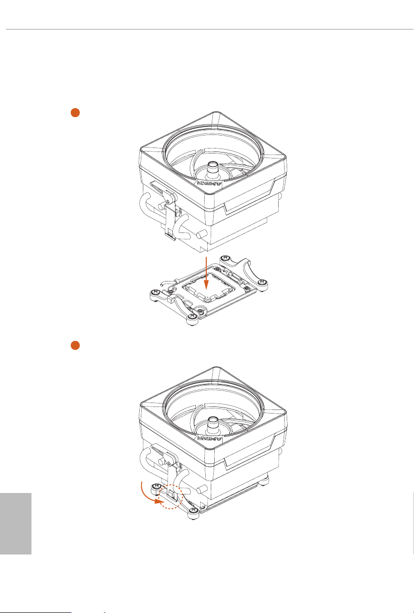
Installing the CPU Cooler (Type 3)
1
2
English
22
Page 27
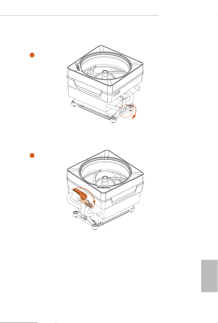
B650E PG-ITX WiFi
3
4
23
English
Page 28

5
CPU_FAN1
English
24
Page 29
B650E PG-ITX WiFi
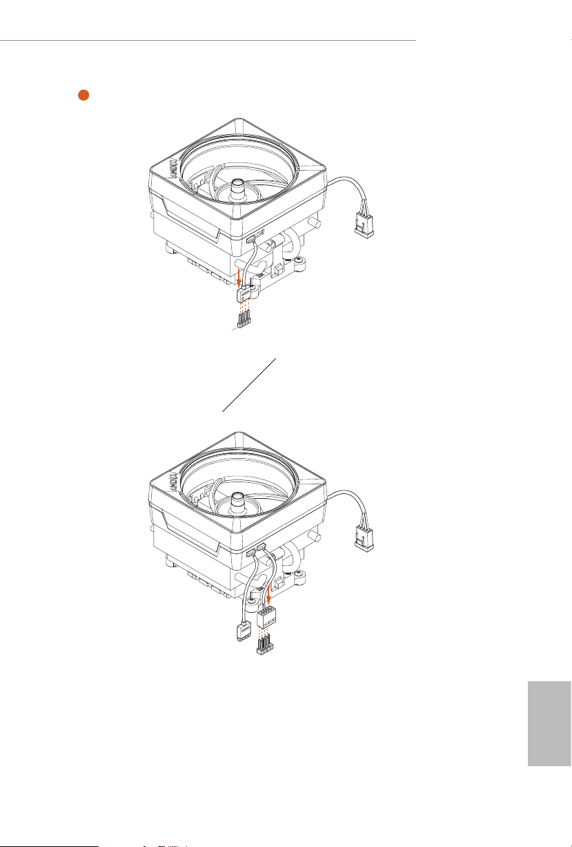
6
CPU_FAN1
RGB_LED1
+12V
or
CPU_FAN1
RGB_LED1
USB_1_2
Please note that only one cable should be used at a time in this step.
If you select RGB_LED1, please install ASRock utility "ASRock Polychrome SYNC".
If you select USB connector, please install AMD utility "SR3 Settings Soware".
*e illustrations shown here are for reference purposes only and may not exactly match
the model you purchase.
English
25
Page 30
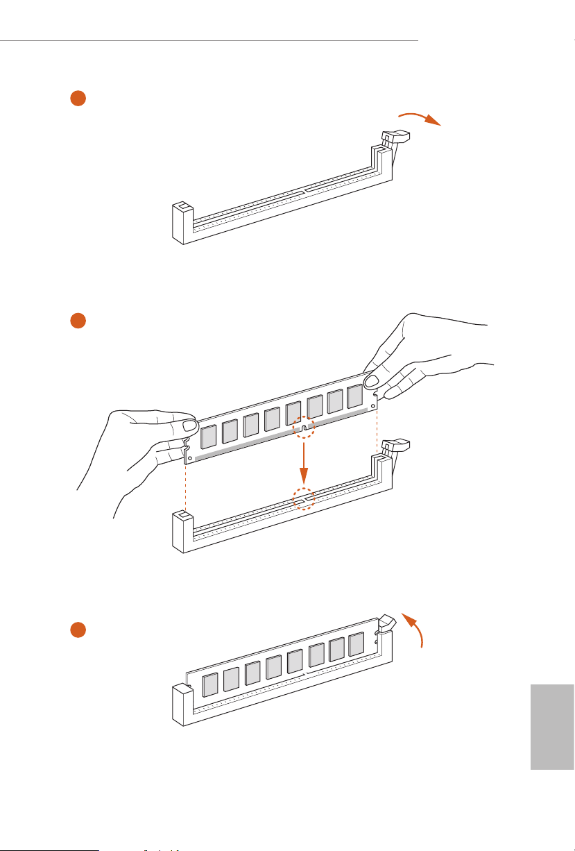
2.3 Installing Memory Modules (DIMM)
is motherboard provides two 288-pin DDR5 (Double Data Rate 5) DIMM slots,
and supports Dual Channel Memory Technology.
1. For dual channel conguration, you always need to install identical (the same
brand, speed, size and chip-type) DDR5 DIMM pairs.
2. It is unable to activate Dual C hannel Memory Technology with only one memory
module installed.
3. It is not allowed to in stall a DDR, DDR2 , DDR3 or DDR4 memory module into a
DDR5 slot; otherwise, this motherboard an d DIMM may be damaged.
4. e DIMM only ts in one correct orientation. It w ill cause per manent d amage to
the mothe rboard and the DIMM if you force the DIMM into the slot at incorrect
orientation.
Recommended Memory Conguration
1 DIMM
A1 B1
V
2 DIMMs
A1 B1
V V
e rst boot may take some time.
Please be patient and refer to the following table for booting time.
*It may vary by dierent setups.
English
26
Memory 1st boot after clear CMOS
2 x 16GB 90 sec
2 x 32GB 150 sec
Page 31
B650E PG-ITX WiFi
1
2
3
English
27
Page 32

2.4 Connecting the Front Panel Header
1
32:(56:
+''/('
5(6(76:
32:(5/('
32:(5/('
2
RESET SW
HDD LED
English
28
3$1(/
System Panel Header
910
Power SW (-) RESET SW (+)
B
Power LED (-)
A
Power LED (+)
12
PANEL1
RESET SW (-)Power SW (+)
HDD LED (-)
HDD LED (+)
Front Panel Wires
D
C
A B C D
Page 33

2.5 Installing the Motherboard
B650E PG-ITX WiFi
29
English
Page 34

2.6 Installing SATA Drives
1
Optical Drive
SATA Drive
2
English
30
SATA Data Cable
Page 35

B650E PG-ITX WiFi
3
4
SATA Power Connector
SATA Data Connector
English
31
Page 36

2.7 Installing a Graphics Card
1
CLICK!
English
32
Page 37

Expansion Slots (PCIe Slots)
ere is 1 PCI Express slot on the motherboard.
Before installing an expansion card, please make sure that the power supply is
switched o or the power cord i s unplugged. Please read the document ation of the
expan sion card and mak e neces sary hardware settings for the card before you start
the installation.
PCIe slots:
PCIE1 (PCIe 5.0 x16 slot) is used for PCIe x16 lane width graphics cards.
B650E PG-ITX WiFi
33
English
Page 38

2.8 Connecting Peripheral Devices
English
34
Page 39
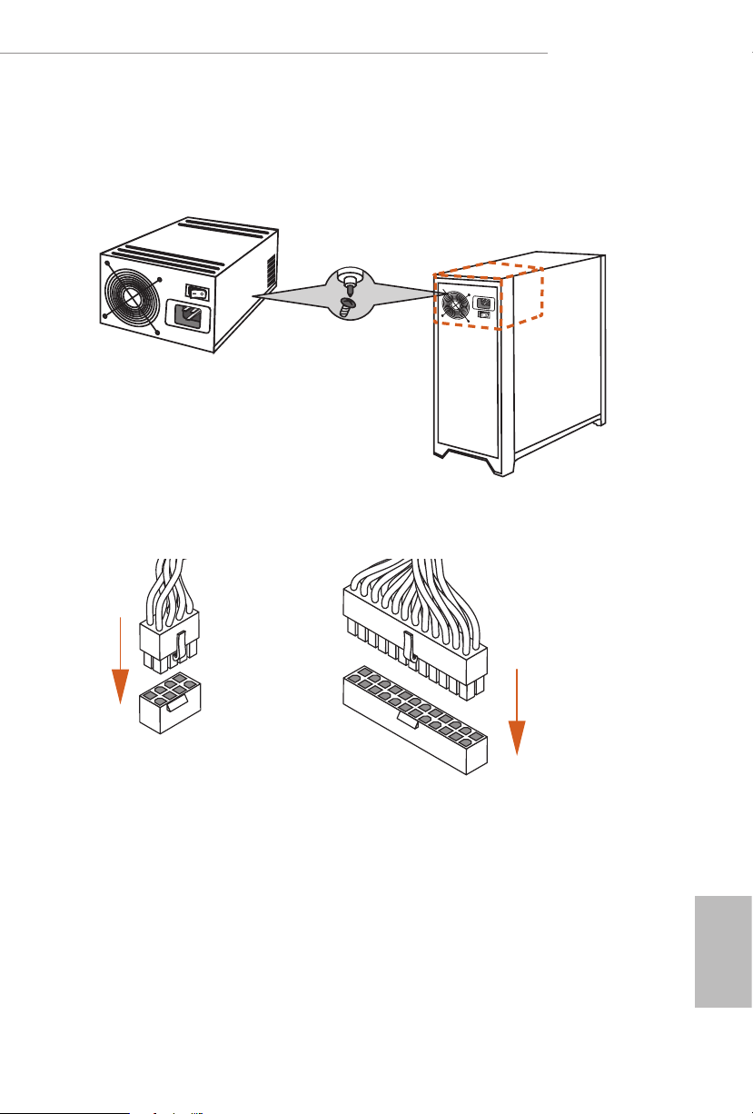
2.9 Connecting the Power Connectors
B650E PG-ITX WiFi
$7;9
$7;3:5
English
35
Page 40

2.10 Power On
1
2
3
4
English
36
Page 41
B650E PG-ITX WiFi
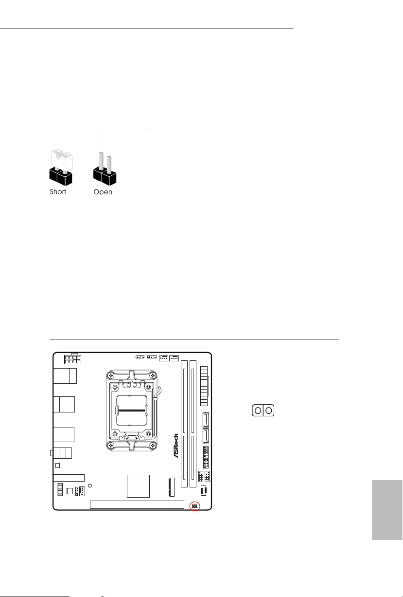
2.11 Jumpers Setup
e illustration shows how jumpers are setup. When the jumper cap is placed on
the pins, the jumper is “Short”. If no jumper cap is placed on the pins, the jumper is
“Open”.
Clear CMOS Jumper
(CLRCMOS1) (see p.6, No. 14)
CLRCMOS1 allows you to clear the data in CMOS. e data in CMOS includes
system setup information such as system password, date, time, and system setup
parameters. To clear and reset the system parameters to default setup, please
turn o the computer and unplug the power cord, then use a jumper cap to short
the pins on CLRCMOS1 for 3 seconds. Please remember to remove the jumper
cap aer clearing the CMOS. If you need to clear the CMOS when you just nish
updating the BIOS, you must boot up the system rst, and then shut it down
before you do the clear-CMOS action.
CLRCMOS1
2-pin Jumper
Short: Clear CMOS
Open: Default
English
37
Page 42
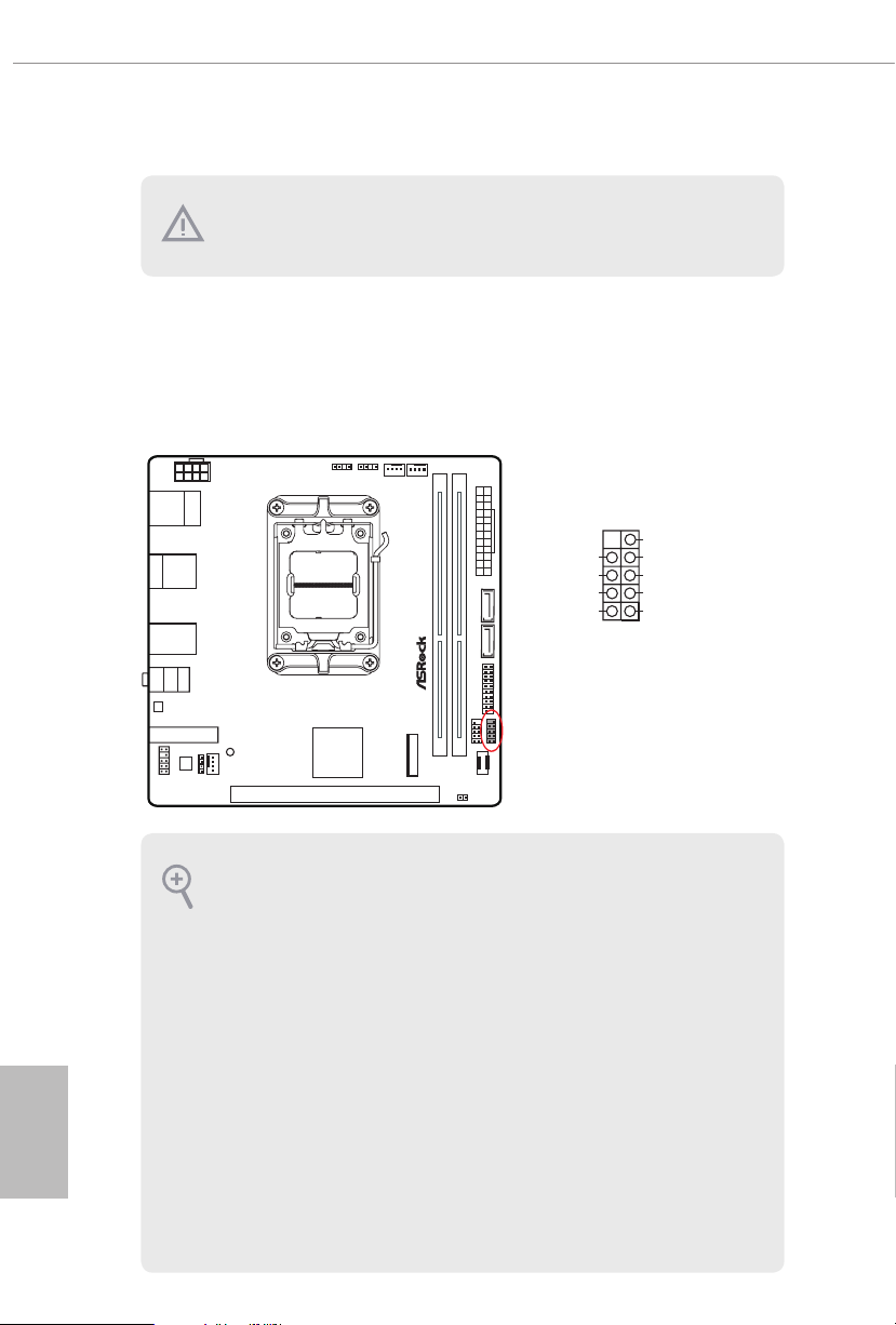
2.12 Onboard Headers and Connectors
Onboard headers and connectors are NOT jumpers. Do NOT place jumpe r caps over
System Panel Header
(9-pin PANEL1) (see p.6, No. 11)
Connect the power button, reset button and system status indicator on the chassis
to this header according to the pin assignments below. Note the positive and
negative pins before connecting the cables.
these headers and conne ctors. Placing jumper caps over the headers and conn ectors
will cause per manent damage to the mothe rboard.
PANEL1
GND
PWR BTN #
PLE D-
PLE D+
GND
RES ET#
GND
HDL ED-
HDL ED+
1
English
38
PWRBTN (Power But ton):
Connec t to the power button on the chassis front panel. You may congure the way
to turn o your system using the power button.
RESET (Reset Button):
Connec t to the reset button on the chassis f ront panel. Pre ss the reset button to
restar t the computer if the computer freezes and fails to perform a normal restart.
PLED (Syste m Power LED):
Connec t to the power status indic ator on the chassis front panel. e LED is on when
the system is operating. e LED keeps blinking when the system is in S1/S3 sleep
state. e LED is o when the system is in S 4 sleep state or powered o (S5).
HDLED (Ha rd Drive Activity LED):
Connec t to the hard drive ac tivity L ED on the chassis front panel. e LED is on
when the hard drive i s reading or writing data.
e front panel design may dier by chassis. A front panel module mainly consists
of power button, reset but ton, power LED, hard drive activity LED, speaker and etc.
When connecting your chassis front panel module to this header, make sure the wire
assig nments and the pin assignments are matched correctly.
Page 43
Please refer to the table below for PLED (System Power LED) indications.
Status Description
Blinking (2Hz) Booting into system
On Booting completed
Blinking till BFG DRAM overclocking failed
On Booting without DRAM
Blinking (1Hz) Entering S3 sleep mode
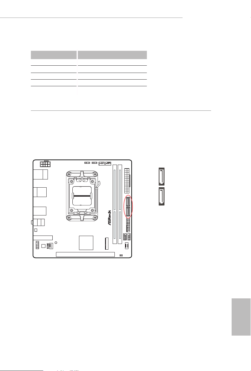
Serial ATA3 Connectors
(SATA3_1) (see p.6, No. 9)
(SATA3_2) (see p.6, No. 8)
ese two SATA3 connectors support SATA data cables for internal storage
devices with up to 6.0 Gb/s data transfer rate.
B650E PG-ITX WiFi
SATA3_1 SATA3_2
English
39
Page 44

USB 2.0 Header
(9-pin USB_5_6) (see p.6, No. 12)
ere is one header on this motherboard. is USB 2.0 header can support two
ports.
USB_5_6
USB 3.2 Gen1 Header
(19-pin USB32_4_5) (see p.6, No. 10)
ere is one header on this motherboard. is USB 3.2 Gen1 header can support
two ports.
English
40
USB32_4_5
Dumm y
IntA _PB_D +
IntA _PB_D -
IntA _PB_S STX+
IntA _PB_S STX-
IntA _PB_S SRX+
IntA _PB_S SRX-
Vbus
1
IntA _PA_D+
IntA _PA_D-
GND
GND
IntA _PA_SS TX+
IntA _PA_SS TX-
GND
GND
IntA _PA_SS RX+
IntA _PA_SS RX-
Vbus
Page 45

B650E PG-ITX WiFi
Front Panel Type C USB 3.2 Gen2x2 Header
(20-pin USB32_TC2) (see p.6, No. 13)
ere is one Front Panel Type C USB 3.2 Gen2x2 Header on this motherboard.
is header is used for connecting a USB 3.2 Gen2x2 module for additional USB 3.2
Gen2x2 ports.
USB32_TC2
USB Type-C Cable
Front Panel Audio Header
(9-pin HD_AUDIO1) (see p.6, No. 17)
is header is for connecting audio devices to the front audio panel.
HD_AUDIO1
OUT _R ET
MIC _R ET
PRE SE NCE #
GN D
High Denition Audio supports Jack S ensing, but the panel wire on the chassis mu st
suppor t HDA to function correctly. Please follow the instr uctions in our manual and
chassis manu al to install your system.
1
OUT 2_ L
J_S EN SE
OUT 2_ R
MIC 2_ R
MIC 2_ L
English
41
Page 46
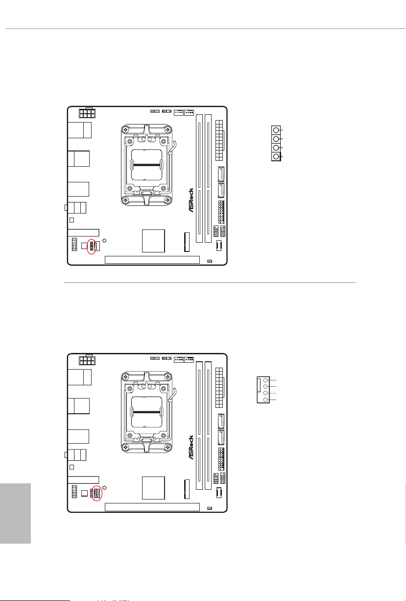
Chassis Speaker Header
(4-pin SPEAKER1) (see p.6, No. 16)
Please connect the chassis speaker to this header.
Chassis/Water Pump Fan Connector
(4-pin CHA_FAN1/WP) (see p.6, No. 15)
is motherboard provides a 4-Pin water cooling
plan to connect a 3-Pin
chassis
water cooler fan, please connect it to Pin 1-3.
SPEAKER1
chassis
fan connectors. If you
SPE AKE R
DUM MY
DUM MY
+5V
1
English
42
CHA_FAN1/WP
GND
1
FAN_VOLTAGE
2
CHA _FA N_S PEE D
3
4
FAN _SP EED _CO NTR OL
Page 47
B650E PG-ITX WiFi
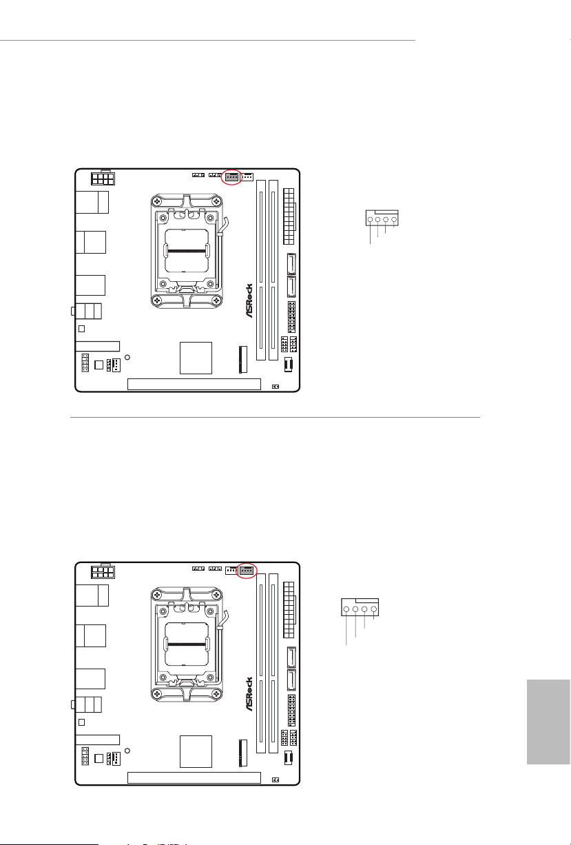
CPU Fan Connector
(4-pin CPU_FAN1) (see p.6, No. 4)
is motherboard provides a 4-Pin CPU fan (Quiet Fan) connector. If you plan to
connect a 3-Pin CPU fan, please connect it to Pin 1-3.
CPU_FAN1
4 3 2 1
GND
+12 V
CPU _FAN _SPE ED
FAN_ SPE ED_C ONT ROL
CPU/Water Pump Fan (M.2 Fan) Connector
(4-pin CPU_FAN2/WP) (see p.6, No. 5)
is motherboard provides a 4-Pin water cooling CPU fan connector. If you plan
to connect a 3-Pin CPU water cooler fan, please connect it to Pin 1-3.
*CPU_FAN2/WP (M.2 fan connector) is connected to the attached fan cable of
ASRock Blazing M.2 Gen5 Fan Heatsink pre-installed on M2_1 socket. Please
refer to page 47 for details.
CPU_FAN2/WP
4 3 2 1
GND
FAN_ VOLTA GE
CPU_ F
AN_S PEED
FAN_S PEED_ CONTR OL
English
43
Page 48

ATX Power Connector
8 5
(24-pin ATXPWR1) (see p.6, No. 7)
is motherboard provides a 24-pin ATX power connector. To use a 20-pin ATX
power supply, please plug it along Pin 1 and Pin 13.
ATXPWR1
12
24
1
13
ATX 12V Power Connector
(8-pin ATX12V1) (see p.6, No. 1)
is motherboard provides a 8-pin ATX 12V power connector. To use a 4-pin
ATX power supply, please plug it a long Pin 1 and Pin 5.
*Warning: Please make sure that the power cable connected is for the CPU and
not the graphics card. Do not plug the PCIe power cable to this
connector.
English
44
ATX12V1
4
1
Page 49

B650E PG-ITX WiFi
Addressable LED Headers
(3-pin ADDR_LED1) (see p.6, No. 2)
(3-pin ADDR_LED2) (see p.6, No. 3)
ese headers are used to connect
to choose from various LED lighting eects.
Caution: Never install the Addressable LED cable in the wrong orientation; otherwise,
the cable may be damaged.
Addressable
LED extension cables which allow users
ADDR_LED2
1
GND
DO_ ADD R
VOU T
ADDR_LED1
1
GND
DO_ ADD R
VOU T
Connect your
to the
LED1 / ADDR_LED2)
Addressable RGB LED
strips
Addressable LED Headers (ADDR_
on the motherboard.
1
1. Never in stall the RGB LED cable in the wrong orientation; other wise, the cable
may be damaged.
2. Before installing or removing your RGB LED cable, plea se power o your system
and unplug the power cord from the power supply. Failure to do so may cause damages to motherboard components.
1. Please note that the RGB LED str ips do not come with the package.
2. e RGB LED header support s WS2812B addressable RGB LED str ip (5V/Data/
GND), with a ma ximum power rating of 3A (5V) and length within 2 meters.
English
45
Page 50

eDP Signal Connector
(40-pin EDP1) (see p.7, No. 18)
is connector on the bottom side of the motherboard is for an LCD monitor that
supports an internal embedded DisplayPort (eDP).
*Please refer to page 53 for further instructions on how to adjust the brightness.
PIN SIGNAL
N/A
1
LCD_BLT_VCC
2
LCD_BLT_VCC
3
LCD_BLT_VCC
4
LCD_BLT_VCC
5
N/A
6
N/A
7
eDP_VARY_BL
8
eDP_BLON
9
BKT_GND
10
BKT_GND
11
BKT_GND
12
BKT_GND
13
eDP_HPD_CON
14
PNL_GND
15
PNL_GND
16
PNL_GND
17
PNL_GND
18
N/A
19
+LVDD
20
+LVDD
21
+LVDD
22
+LVDD
23
GND
24
eDP_AUX#_CON
25
eDP_AUX_CON
26
GND
27
eDP_TX0_CON
28
eDP_TX#0_CON
29
GND
30
eDP_TX1_CON
31
eDP_TX#1_CON
32
GND
33
N/A
34
N/A
35
GND
36
N/A
37
N/A
38
GND
39
N/A
40
English
46
Page 51

B650E PG-ITX WiFi
2.13 M.2 SSD Module Installation Guide (M2_1)
e M.2 is a small size and versatile card edge connector that aims to replace mPCIe and
mSATA. e Blazing M.2 Socket (M2_1, Key M) supports type 2280 PCIe Gen5x4 (128
Gb/s) mode.
is motherboard comes with ASRock Blazing M.2 Gen5 Fan Heatsink (pre-installed
on M2_1 socket), which is a M.2 SSD heatsink with fan that enables PCIe Gen5 SSD to
achieve optimal heat dissipation.
ASRock Blazing M.2 Gen5 Fan Heatsink Dimension: 94 .5*23.0*35.3mm / Fan Speed:
12000 rpm.
Installing the M.2 SSD Module
Step 1
Prepare a M.2 SSD module and the
screw.
Step 2
No. 1
Nut Location A
PCB Length 8cm
Module Type Type 2280
Depending on the PCB t ype and
length of your M.2 SSD module, nd
the corresponding nut location to be
used.
English
47
Page 52

2
Step 3
Before installing a M.2 SSD
module, please loosen the screws to
1
1
remove Blazing M.2 Gen5 Fan
Heatsink.
*Please remove the protective lms
on the bottom side of Blazing M.2
Gen5 Fan Heatsink before you
install a M.2 SSD module.
Step 4
Align and gently insert the M.2 SSD
module into the M.2 slot. Please
be aware that the M.2 SSD module
only ts in one orientation.
A
English
48
A
o
20
Page 53

Step 5
Before securing Blazing M.2 Gen5
Fan Heatsink, make sure to align the
notch on the SSD to the stando on
the motherboard; otherwise, the SSD
module may be damaged.
Correct Installation:
e SSD's PCB is in proper place, and Blazing
M.2 Gen5 Fan Heatsink can be screwed in.
B650E PG-ITX WiFi
Incorrect Installation:
e SSD's PCB sits between Blazing M.2
Gen5 Fan Heatsink and stando. Do not
continue.
English
49
Page 54

1
2
Step 6
Tighten the screws with a screwdriver
to secure the module and Blazing M.2
3
Gen5 Fan Heatsink into place in the
order shown. Tighten screw opposite
the M.2 connector rst (2), and
then tighten the one next to the M.2
connector (3).
*Please do not overtighten the screw
as this might damage the module and
Blazing M.2 Gen5 Fan Heatsink.
Step 7
Plug the attached fan cable to M.2 fan
connector (CPU_FAN2/WP, see p.6,
No. 5) on the motherboard.
English
50
For the latest updates of M.2 SSD module support list, please visit our website for details:
http://ww w.asrock.com
Page 55
B650E PG-ITX WiFi
2.14 M.2 SSD Module Installation Guide (M2_2)
e M.2 is a small size and versatile card edge connector that aims to replace mPCIe and
mSATA. e Hyper M.2 Socket (M2_2, Key M) supports type 2280 PCIe Gen4x4 (64 Gb/s)
mode.
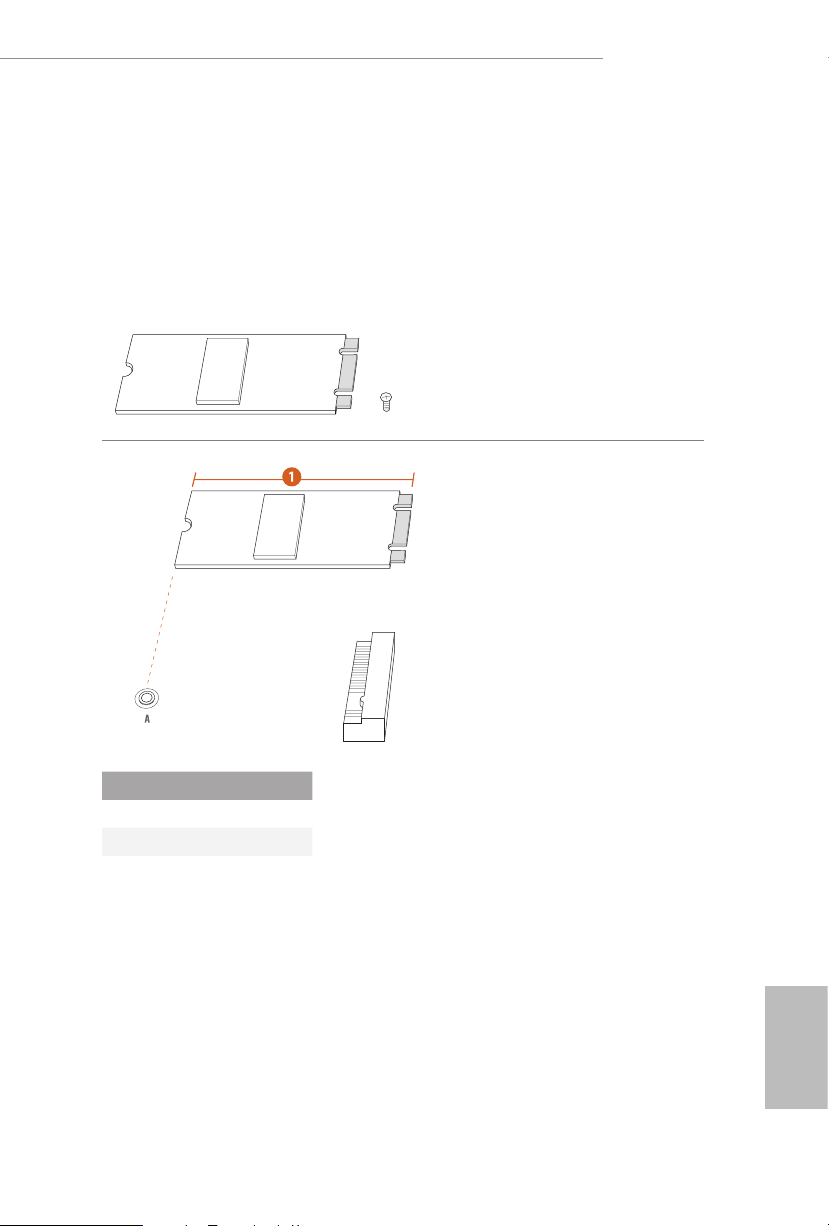
Installing the M.2 SSD Module
Step 1
Prepare a M.2 SSD module and the
screw.
Step 2
Depending on the PCB t ype and
length of your M.2 SSD module, nd
the corresponding nut location to be
used.
No. 1
Nut Location A
PCB Length 8cm
Module Type Type 2280
English
51
Page 56

Step 3
Peel o the yellow protective lm on
the nut to be used. Align and gently
insert the M.2 SSD module into the
M.2 slot. Please be aware that the
M.2 SSD module only ts in one
A
orientation.
English
A
o
20
Step 4
Tighten the screw with a screwdriver
to secure the module into place.
Please do not overtighten the screw
NUT1NUT2
as this might damage the module.
For the latest updates of M.2 SSD module support list, please visit our website for details:
http://ww w.asrock.com
52
Page 57
B650E PG-ITX WiFi
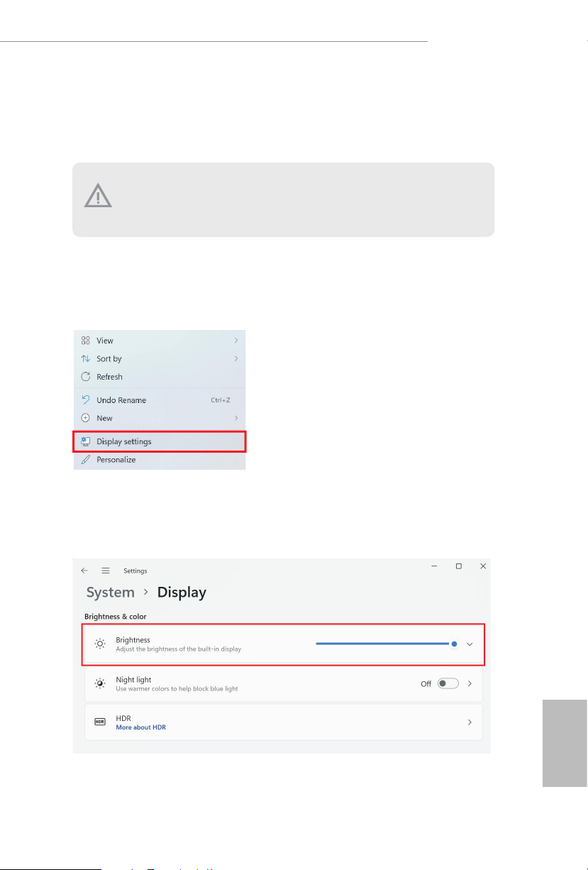
2.15 Change Screen Brightness for eDP in Windows®
is section explains how to change screen brightness in Windows® when you use
an eDP panel.
e follo wing is a setup example for Windows® 11. Setup procedures may var y from
dierent operating syste ms.
Setup Guide
Step 1
Right click on desktop. Select Display settings.
Step 2
In System > Display, select Brightness. Move the slider to ne-tune the brightness
level.
English
53
Page 58
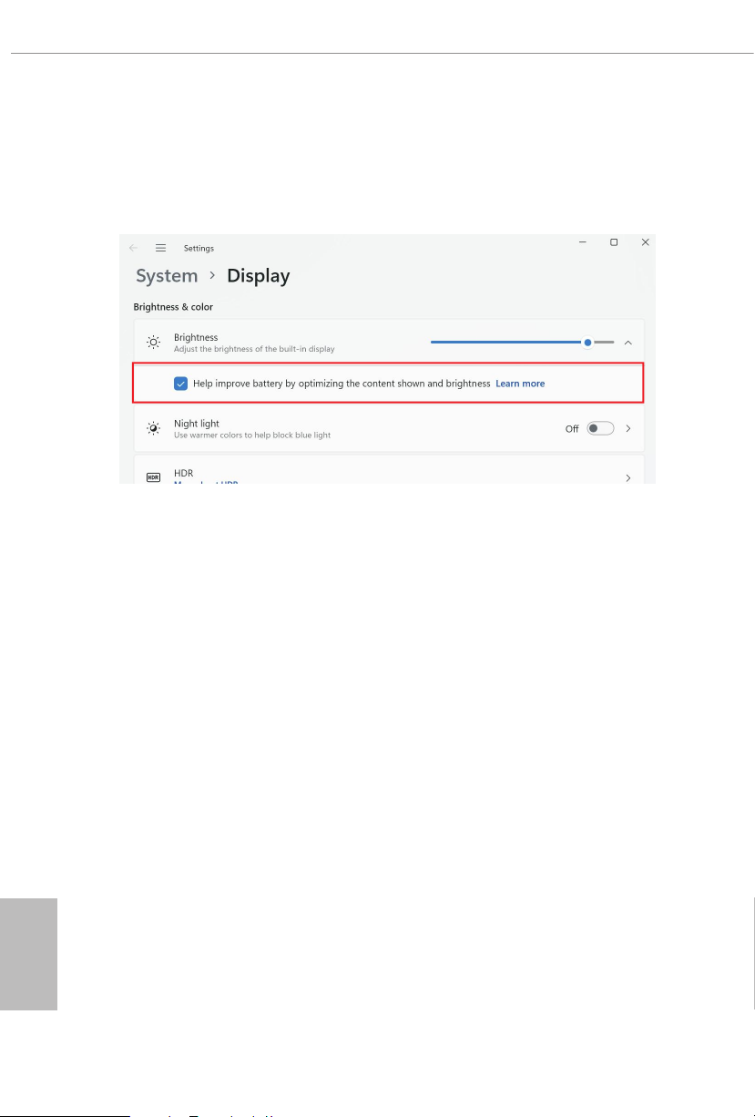
Step 3
You might also see another check box displayed: Help improve battery by
optimizing the content shown and brightness. Select the check box to turn on the
content adaptive brightness control if needed.
English
54
Page 59

Version 1.0
Published September 2022
Copyright©2022 ASRock INC. All rights reserved.
Copyright Notice:
No part of this documentation may be reproduced, transcribed, transmitted, or
translated in any language, in any form or by any means, except duplication of
documentation by the purchaser for backup purpose, without written consent of
ASRock Inc.
Products and corporate names appearing in this documentation may or may not
be registered trademarks or copyrights of their respective companies, and are used
only for identication or explanation and to the owners’ benet, without intent to
infringe.
Disclaimer:
Specications and information contained in this documentation are furnished for
informational use only and subject to change without notice, and should not be
constructed as a commitment by ASRock. ASRock assumes no responsibilit y for
any errors or omissions that may appear in this documentation.
With respect to the contents of this documentation, ASRock does not provide
warranty of any kind, either expressed or implied, including but not limited to
the implied warranties or conditions of merchantability or tness for a particular
purpose.
In no event shall ASRock, its directors, ocers, employees, or agents be liable for
any indirect, special, incidental, or consequential damages (including damages for
loss of prots, loss of business, loss of data, interruption of business and the like),
even if ASRock has been advised of the possibility of such damages arising from
any defect or error in the documentation or product.
is device complies with Part 15 of the FCC Rules. Operation is subject to the following
two conditions:
(1) this device may not cause harmful interference, and
(2) this device must accept any interference received, including interference that
may cause undesired operation.
is equipment has been tested and found to comply with the limits for a Class B digital
device, pursuant to part 15 of the FCC Rules. ese limits are designed to provide
reasonable protection against harmful interference in a residential installation. is
equipment generates, uses and can radiate radio frequency energ y and, if not installed
and used in accordance with the instructions, may cause harmful interference to radio
communications. However, there is no guarantee that interference will not occur in a
particular installation. If this equipment does cause harmful interference to radio or
television reception, which can be determined by turning the equipment o and on, the
user is encouraged to try to correct the interference by one or more of the following
measures:
- Reorient or relocate the receiving antenna.
- Increase the separation between the equipment and receiver.
- Connect the equipment into an outlet on a circuit dierent from that to which the
receiver is connected.
- Consult the dealer or an experienced radio/TV technician for help.
Page 60

e terms HDMI® and HDMI High-Denition Multimedia Interface, and the HDMI
logo are trademarks or registered trademarks of HDMI Licensing LLC in the United
States and other countries.
WARNING
THIS PRODUCT CONTAINS A BUTTOON BATTERY
If swallowed, a button battery can cause serious injury or death.
Please keep batteries out of sight or reach of children.
CALIFORNIA, USA ONLY
e Lithium batter y adopted on this motherboard contains Perchlorate, a toxic substance
controlled in Perchlorate Best Management Practices (BMP) regulations passed by the
California Legislature. When you discard the Lithium battery in California, USA, please
follow the related regulations in advance.
“Perchlorate Material-special handling may apply, see www.dtsc.ca.gov/hazardouswaste/
perchlorate”
AUSTRALIA ONLY
Our goods come with guarantees that cannot be excluded under the Australian Consumer
Law. You are entitled to a replacement or refund for a major failure and compensation for
any other reasonably foreseeable loss or damage caused by our goods. You are also entitled
to have the goods repaired or replaced if the goods fail to be of acceptable quality and the
failure does not amount to a major failure. If you require assistance please call ASRock Tel
: +886-2-28965588 ext.123 (Standard International call charges apply)
Page 61

ASRock INC. hereby declares that this device is in compliance with the essential requirements and other relevant provisions of related UKCA Directives. Full text of UKCA
declaration of conformity is available at: http://www.asrock.com
ASRock INC. hereby declares that this device is in compliance with the essential requirements and other relevant provisions of related Directives. Full text of EU declaration of
conformity is available at: http://www.asrock.com
ASRock follows the green design concept to design and manufacture our products, and
makes sure that each stage of the product life cycle of ASRock product is in line with
global environmental regulations. In addition, ASRock disclose the relevant information
based on regulation requirements.
Please refer to https://www.asrock.com/general/about.asp?cat=Responsibility for information disclosure based on regulation requirements ASRock is complied with.
DO NOT throw the motherboard in municipal waste. is product has been
designed to enable proper reuse of parts and recycling. is symbol of the
crossed out wheeled bin indicates that the product (electrical and electronic
equipment) should not be placed in municipal waste. Check local regulations
for disposal of electronic products.
CE Warning
is device complies with directive 2014/53/EU issued by the Commision of the
European Community.
is equipment complies with EU radiation exposure limits set forth for an
uncontrolled environment.
is equipment should be installed and operated with minimum distance 20cm
between the radiator & your body.
Page 62
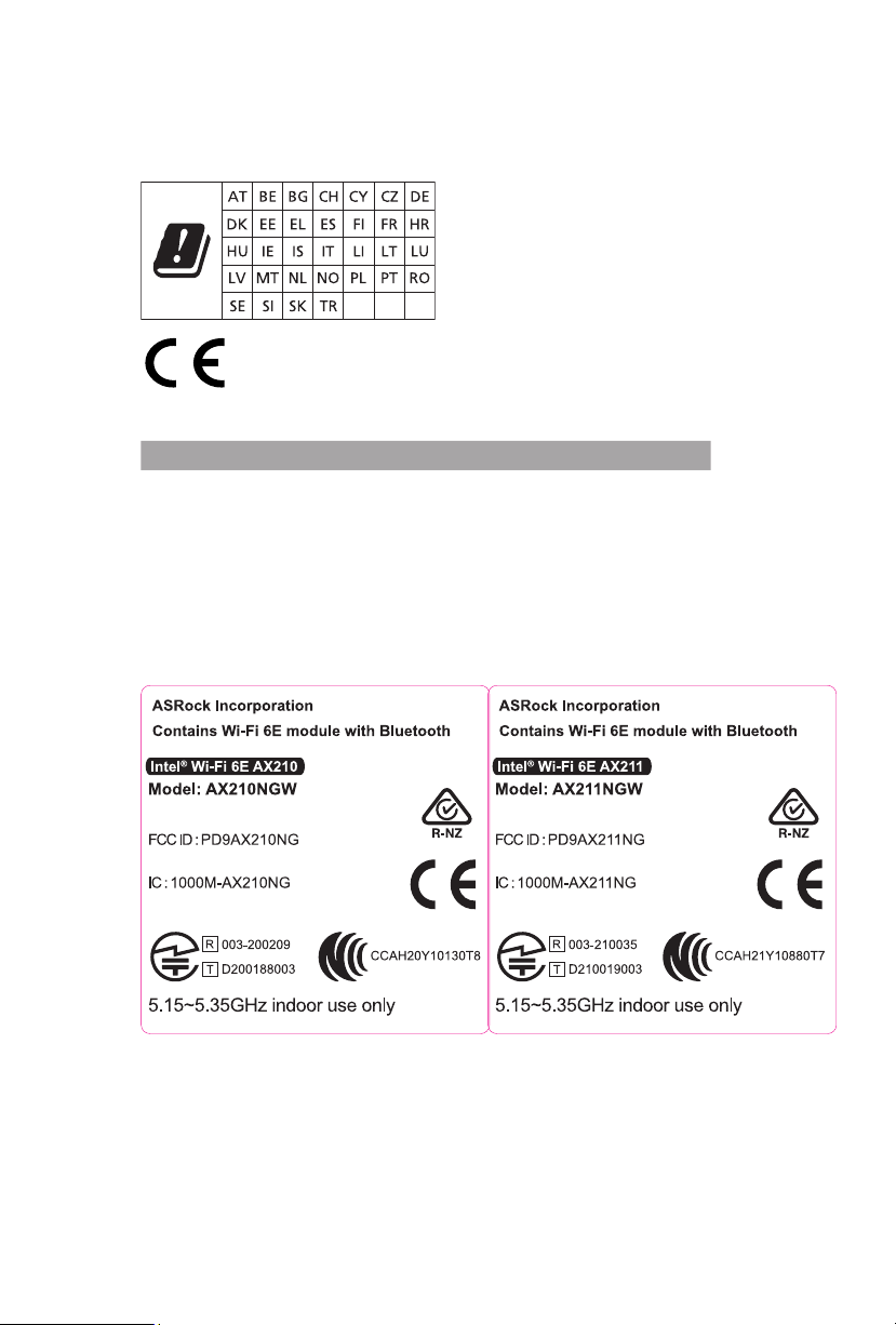
Operations in the 5.15-5.35GHz band are restricted to indoor usage only.
Radio transmit power per transceiver type
Function Frequency Maximum Output Power (EIRP)
2400-2483.5 MHz 18.5 + / -1.5 dbm
5150-5250 MHz 21.5 + / -1.5 dbm
WiFi
Bluetooth 2400-2483.5 MHz 8.5 + / -1.5 dbm
5250-5350 MHz
5470-5725 MHz
18.5 + / -1.5 dbm (no TPC)
21.5 + / -1.5 dbm (TPC)
25.5 + / -1.5 dbm (no TPC)
28.5 + / -1.5 dbm (TPC)
 Loading...