

ASRock B460M Steel Legend Service Manual


Version 1.0
Published May 2020
Copyright©2020 ASRock INC. All rights reserved.
Copyright Notice:
No part of this documentation may be reproduced, transcribed, transmitted, or
translated in any language, in any form or by any means, except duplication of
documentation by the purchaser for backup purpose, without written consent of
ASRock Inc.
Products and corporate names appearing in this documentation may or may not
be registered trademarks or copyrights of their respective companies, and are used
only for identication or explanation and to the owners’ benet, without intent to
infringe.
Disclaimer:
Specications and information contained in this documentation are furnished for
informational use only and subject to change without notice, and should not be
constructed as a commitment by ASRock. ASRock assumes no responsibility for
any errors or omissions that may appear in this documentation.
With respect to the contents of this documentation, ASRock does not provide
warranty of any kind, either expressed or implied, including but not limited to
the implied warranties or conditions of merchantability or tness for a particular
purpose.
In no event shall ASRock, its directors, ocers, employees, or agents be liable for
any indirect, special, incidental, or consequential damages (including damages for
loss of prots, loss of business, loss of data, interruption of business and the like),
even if ASRock has been advised of the possibility of such damages arising from any
defect or error in the documentation or product.
is device complies with Part 15 of the FCC Rules. Operation is subject to the following
two conditions:
(1) this device may not cause harmful interference, and
(2) this device must accept any interference received, including interference that
may cause undesired operation.
CALIFORNIA, USA ONLY
e Lithium battery adopted on this motherboard contains Perchlorate, a toxic substance
controlled in Perchlorate Best Management Practices (BMP) regulations passed by the
California Legislature. When you discard the Lithium battery in California, USA, please
follow the related regulations in advance.
“Perchlorate Material-special handling may apply, see ww w.dtsc.ca.gov/hazardouswaste/
perchlorate”
ASRock Website: http://www.asrock.com

AUSTRALIA ONLY
Our goods come with guarantees that cannot be excluded under the Australian
Consumer Law. You are entitled to a replacement or refund for a major failure and
compensation for any other reasonably foreseeable loss or damage caused by our
goods. You are also entitled to have the goods repaired or replaced if the goods fail
to be of acceptable quality and the failure does not amount to a major failure. If
you require assistance please call ASRock Tel : +886-2-28965588 ext.123 (Standard
International call charges apply)
e terms HDMI® and HDMI High-Denition Multimedia Interface, and the
HDMI logo are trademarks or registered trademarks of HDMI Licensing LLC in the
United States and other countries.

Contents
Chapter 1 Introduction 1
1.1 Package Contents 1
1.2 Specications 2
1.3 Motherboard Layout 7
1.4 I/O Panel 9
Chapter 2 Installation 11
2.1 Installing the CPU 12
2.2 Installing the CPU Fan and Heatsink 15
2.3 Installing Memory Modules (DIMM) 16
2.4 Expansion Slots (PCI Express Slots) 18
2.5 Jumpers Setup 19
2.6 Onboard Headers and Connectors 20
2.7 Post Status Checker 25
2.8 CrossFireXTM and Quad CrossFireXTM Operation Guide 26
2.8.1 Installing Two CrossFireXTM-Ready Graphics Cards 26
2.8.2 Driver Installation and Setup 28
2.9 M.2_SSD (NGFF) Module Installation Guide (M2_1) 29
2.10 M.2_SSD (NGFF) Module Installation Guide (M2_2) 32
2.11 M.2 WiFi/BT Module Installation Guide (M2_3) 36
Chapter 3 Software and Utilities Operation 38
3.1 Installing Drivers 38
3.2 ASRock Motherboard Utility (A-Tuning) 39

3.2.1 Installing ASRock Motherboard Utility (A-Tuning) 39
3.2.2 Using ASRock Motherboard Utility (A-Tuning) 39
3.3 ASRock Live Update & APP Shop 42
3.3.1 UI Overview 42
3.3.2 Apps 43
3.3.3 BIOS & Drivers 46
3.3.4 Setting 47
3.4 Nahimic Audio 48
3.5 ASRock Polychrome SYNC 49
Chapter 4 UEFI SETUP UTILITY 52
4.1 Introduction 52
4.2 EZ Mode 53
4.3 Advanced Mode 54
4.3.1 UEFI Menu Bar 54
4.3.2 Navigation Keys 55
4.4 Main Screen 56
4.5 OC Tweaker Screen 57
4.6 Advanced Screen 67
4.6.1 CPU Conguration 68
4.6.2 Chipset Conguration 70
4.6.3 Storage Conguration 73
4.6.4 Intel(R) Thunderbolt 74
4.6.5 Super IO Conguration 75
4.6.6 ACPI Conguration 76

4.6.7 USB Conguration 77
4.6.8 Trusted Computing 78
4.7 Tools 79
4.8 Hardware Health Event Monitoring Screen 81
4.9 Security Screen 85
4.10 Boot Screen 86
4.11 Exit Screen 89
B460M Steel Legend
Chapter 1 Introduction
ank you for purchasing ASRock B460M Steel Legend motherboard, a reliable
motherboard produced under ASRock’s consistently stringent quality control.
It delivers excellent performance with robust design conforming to ASRock’s
commitment to quality and endurance.
In this documentation, Chapter 1 and 2 contains the introduction of the
motherboard and step-by-step installation guides. Chapter 3 contains the operation
guide of the soware and utilities. Chapter 4 contains the conguration guide of
the BIOS setup.
Becau se the motherboard specications and the BIOS soware might be updated, the
content of this documentation will be subject to change without notice. In case any
modications of this documentation occur, the upd ated version will be available on
ASRock’s website w ithout f urther notice. If you require technical support related to
this motherboard, please vi sit our website for s pecic information about the model
you are using. You may nd the l atest VGA cards and CPU suppor t list on ASRock’s
website a s well. ASRock website http://www.asrock.com.
1.1 Package Contents
ASRock B460M Steel Legend Motherboard (Micro ATX Form Factor)
•
ASRock B460M Steel Legend Quick Installation Guide
•
ASRock B460M Steel Legend Support CD
•
1 x I/O Panel Shield
•
2 x Serial ATA (SATA) Data Cables (Optional)
•
3 x Screws for M.2 Sockets (Option al)
•
1 x Stando for M.2 Socket (Optional)
•
English
1

1.2 Specications
Platform
CPU
Chipset
Memory
•
•
•
•
•
•
•
•
•
* Please refer to Memory Support List on ASRock's website for
more information. (http://www.asrock.com/)
* CoreTM (i9/i7) support DDR4 up to 2933; CoreTM (i5/i3),
Pentium® and Celeron® support DDR4 up to 2666.
•
•
•
•
Micro ATX Form Factor
Suppor ts 10th Gen Intel® CoreTM Processors (Socket 1200)
Digi Power design
9 Power Phase design
Supports Intel® Turbo Boost Ma x 3.0 Technology
Intel® B460
Dual Channel DDR4 Memory Technology
4 x DDR4 DIMM Slots
Supports DDR4 2933/2800/2666/2400/2133 non-ECC, un-
buered memory
Supports ECC UDIMM memory modules (operate in non-
ECC mode)
Max. capacity of system memory: 128GB
Supports Intel® Extreme Memory Prole (XMP) 2.0
15μ Gold Contact in DIMM Slots
English
2
Expansion
Slot
Graphics
2 x PCI Express 3.0 x16 Slots (PCIE1/PCIE3: single at x16
•
(PCIE1); dual at x16 (PCIE1) / x4 (PCIE3))
* Supports NVMe SSD as boot disks
1 x PCI Express 3.0 x1 Slot
•
Supports AMD Quad CrossFireXTM and CrossFireXTM
•
1 x M.2 Socket (Key E), supports type 2230 WiFi/BT module
•
Intel® UHD Graphics Built-in Visuals and the VGA outputs
•
can be supported only with processors which are GPU
integrated.
Hardware Accelerated Codecs: AVC/H.264, HEVC/H.265
•
8bit, HEVC/H.265 10bit, VP8, VP9 8bit, VP9 10bit, MPEG 2,
MJ PEG, VC-1

B460M Steel Legend
* VP9 10bit and VC-1 are for decode only.
* VP8 and VP9 encode are not supported by Windows OS.
Graphics, Media & Compute: Microso DirectX 12, OpenGL
•
4.5, Intel® Built In Visuals, Intel® Quick Sync Video, Hybrid /
Switchable Graphics, OpenCL 2.1
Display & Content Security: Rec. 2020 (Wide Color Gamut),
•
Microso PlayReady 3.0, Intel® SGX Content Protection,
UHD/HDR Blu-ray Disc
Dual graphics output: support HDMI and DisplayPort 1.4
•
ports by independent display controllers
Supports HDMI 1.4 with max. resolution up to 4K x 2K
•
(4096x2160) @ 30Hz
Supports DisplayPort 1.4 with max. resolution up to 4K x 2K
•
(4096x2304) @ 60Hz
Supports Auto Lip Sync, Deep Color (12bpc), xvYCC and
•
HBR (High Bit Rate Audio) with HDMI 1.4 Port (Compliant
HDMI monitor is required)
Supports HDCP 2.3 with HDMI 1.4 and DisplayPort 1.4
•
Ports
Supports 4K Ultra HD (UHD) playback with HDMI 1.4 and
•
DisplayPort 1.4 Ports
Audio
LAN
7.1 CH HD Audio with Content Protection (Realtek
•
ALC1200 Audio Codec)
Premium Blu-ray Audio support
•
Supports Surge Protection
•
PCB Isolate Shielding
•
Individual PCB Layers for R/L Audio Channel
•
Gold Audio Jacks
•
Nahimic Audio
•
2.5 Gigabit LAN 10/100/1000/2500 Mb/s
•
Dragon RTL8125BG
•
Supports Dragon 2.5G LAN Soware
•
- Smart Auto Adjust Bandwidth Control
- Visual User Friendly UI
- Visual Network Usage Statistics
- Optimized Default Setting for Game, Browser, and
Streaming Modes
- User Customized Priority Control
English
3

Rear Panel
I/O
Storage
Supports Wake-On-LAN
•
Supports Lightning/ESD Protection
•
Supports Energy Ecient Ethernet 802.3az
•
Supports PXE
•
1 x Antenna Bracket
•
1 x PS/2 Mouse/Keyboard Port
•
1 x HDMI Port
•
1 x DisplayPort 1.4
•
1 x Optical SPDIF Out Port
•
2 x USB 2.0 Ports (Supports ESD Protection)
•
4 x USB 3.2 Gen1 Type-A Ports (Supports ESD Protection)
•
1 x USB 3.2 Gen1 Type-C Port (Supports ESD Protection)
•
1 x RJ-45 LAN Port with LED (ACT/LINK LED and SPEED
•
LED)
HD Audio Jacks: Rear Speaker / Centra l / Bass / Line in /
•
Front Speaker / Microphone (Gold Audio Jacks)
6 x SATA3 6.0 Gb/s Connectors, support RAID (RAID 0,
•
RAID 1, RAID 5, RAID 10, Intel Rapid Storage Technology
17), NCQ, AHCI and Hot Plug*
* If M2_2 is occupied by a SATA-type M.2 device, SATA3_0 will
be disabled.
1 x Ultra M.2 Socket (M2_1), supports M Key type
•
2242/2260/2280 M.2 PCI Express module up to Gen3 x4
(32 Gb/s)**
1 x Ultra M.2 Socket (M2_2), supports M Key ty pe
•
2260/2280 M.2 SATA3 6.0 Gb/s module and M.2 PCI Ex-
press module up to Gen3 x4 (32 Gb/s)**
** Supports Intel® OptaneTM Tech nolo gy (M 2_ 1)
** Supports NVMe SSD as boot disks
** Supports ASRock U.2 Kit
English
4

Connector
B460M Steel Legend
1 x SPI TPM Header
•
1 x Chassis Intrusion and Speaker Header
•
1 x RGB LED Header
•
* Supports in total up to 12V/3A, 36W LED Strip
2 x Addressable LED Headers
•
* Support in total up to 5V/3A, 15W LED Strip
1 x CPU Fan Connector (4-pin)
•
* e CPU Fan Connector supports the CPU fan of ma ximum
1A (12W) fan power.
1 x CPU/Water Pump Fan Connector (4-pin) (Smart Fan
•
Speed Control)
* e CPU/Water Pump Fan supports the water cooler fan of
maximum 2A (24W) fan power.
4 x Chassis/Water Pump Fan Connectors (4-pin) (Smart Fan
•
Speed Control)
* e Chassis/Water Pump Fan supports the water cooler fan of
maximum 2A (24W) fan power.
* CPU_FAN2/WP, CHA_FAN1/WP, CHA_FAN2/WP, CHA_
FAN3/WP and CHA_FAN4/WP can auto detect if 3-pin or 4-pin
fan is in use.
1 x 24 pin ATX Power Connector (Hi-Density Power
•
Connec tor)
1 x 8 pin 12V Power Connector (Hi-Density Power
•
Connec tor)
1 x Front Panel Audio Connector
•
1 x underbolt AIC Connector (5-pin) (Supports ASRock
•
underbolt 3 AIC R2.0 Card only)
2 x USB 2.0 Headers (Support 4 USB 2.0 ports) (Supports
•
ESD Protection)
1 x USB 3.2 Gen1 Header (Supports 2 USB 3.2 Gen1 ports)
•
(Supports ESD Protection)
BIOS
Feature
AMI UEFI Legal BIOS with multilingual GUI support
•
ACPI 6.0 Compliant wake up events
•
SMBIOS 2.7 Support
•
CPU Core/Cache, GT, DRAM, VPPM, PCH 1.05V, VCCST,
•
VCCSA Voltage Multi-adjustment
English
5
Temperature Sensing: CPU, CPU/Water Pump, Chassis/Wa-
Hardware
Monitor
•
ter Pump Fans
Fan Tachometer: CPU, CPU/Water Pump, Chassis/Water
•
Pump Fans
Quiet Fan (Auto adjust chassis fan speed by CPU tempera-
•
ture): CPU, CPU/Water Pump, Chassis/Water Pump Fans
Fan Multi-Speed Control: CPU, CPU/Water Pump, Chassis/
•
Water Pump Fans
CASE OPEN detection
•
Voltage monitoring: +12V, +5V, +3.3V, CPU Vcore, DRAM,
•
VPPM, PCH, VCCSA, VCCST
Microso® Windows® 10 64-bit
OS
Certications
* For detailed product information, please visit our website: http://www.asrock .com
Please realiz e that the re is a certain r isk involved with o verclocking, including
adjusting the setting in the BIOS, applying Untied Overclocking Technology, or using
third-party overclocking tool s. Overclocking may aect your s ystem’s stability, or
even cause dam age to the components and devices of your system. It should be done
at your own risk and expense. We are not responsible for poss ible damage caused by
overclocking.
•
FCC, CE
•
ErP/EuP Ready (ErP/EuP ready power supply is required)
•
English
6
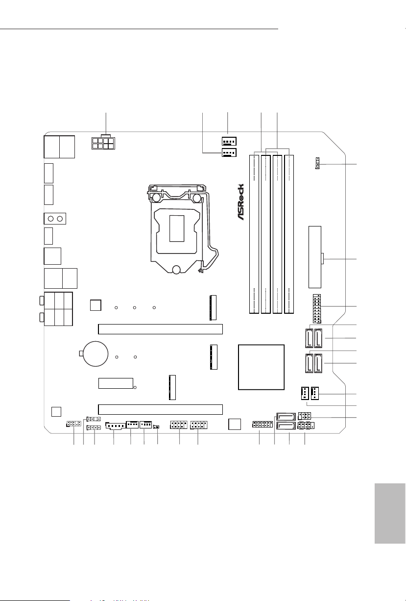
1.3 Motherboard Layout
ATXP WR 1
HDLED RESET
PLED PWRBTN
PANEL1
1
RoHS
4
CPU_FAN1
5
1
PCIE1
10
DDR 4_A2 (6 4 bit, 28 8-pin m odule )
DDR 4_A1 (6 4 bit, 28 8-pin m odule)
DDR 4_B2 (6 4 bit, 28 8-pin m odule )
DDR 4_B1 (6 4 bit, 28 8-pin m odule )
SATA3_2
SATA3_3
9
CLRMOS1
1
1
HD_AUDIO1
M2_1
Top:
RJ-45
CHA_FAN4
/WP
USB 3.2 Gen1
USB3_TC_1
PCIE3
7
8
3
USB5_6
1
27
PCIE2
USB 3.2 Gen1
T: USB3_4
B: USB3_3
M2_3
USB2. 0
T: USB1
B: USB 2
PS2
Keyb oard
/Mou se
2
1
ADDR_LED 1
6
1
SPI_TPM_J1
T B1
1
ADDR_LED2
1
RGB_LED1
1
CHA_FAN2
/WP
24
26
22
USB3_4
CPU_FAN2/WP
12
SATA3_4
SATA3_5
11
M2_2
USB 3.2 Gen1
T:
USB3_2
B:
USB3_1
13
14
15
16
18
21
20
17
28
CMOS
Battery
SPK_CI1
1
SATA3_0
SATA3_1
Intel
B460
1
USB3_5 _6
B4 60 M Ste el L eg en d
ATX12V1
Ultra M.2
PCIe Gen3x4
CHA_FAN3
/WP
19
BIOS
ROM
25
CHA_FAN1
/WP
23
DP1
HDMI 1
Top:
Central/Bass
Cente r:
REAR SP K
Top:
LINE IN
Cente r:
FRONT
Botto m:
Optic al
SPDIF
Botto m:
MIC IN
LAN
AUDIO
CODEC
B460M Steel Legend
English
7

No. Description
1 ATX 12V Power Connector (ATX12V1)
2 CPU/Water Pump Fan Connector (CPU_FAN2/WP)
3 CPU Fan Connector (CPU_FAN1)
4 2 x 288-pin DDR4 DIMM Slots (DDR4_A1, DDR4_B1)
5 2 x 288-pin DDR4 DIMM Slots (DDR4_A2, DDR4_B2)
6 Addressable LED Header (ADDR_LED1)
7 ATX Power Connector (ATXPWR1)
8 USB 3.2 Gen1 Header (USB3_ 5_6)
9 SATA3 Connector (SATA3_2)
10 SATA3 Connector (SATA3_3)
11 SATA3 Con ne ctor (SATA3_4)
12 SATA3 Connector (SATA3_5)
13 Chassis/Water Pump Fan Connector (CHA_FAN3/WP)
14 Chassis/Water Pump Fan Connector (CHA_FAN4/WP)
15 Chassis Intrusion and Speaker Header (SPK_CI1)
16 System Panel Header (PANEL1)
17 SATA3 Connector (SATA3_0)
18 SATA3 Connector (SATA3_1)
19 SPI TPM Header (SPI_TPM_J1)
20 USB 2.0 Header (USB5_6)
21 USB 2.0 Header (USB3_4)
22 Clear CMOS Jumper (CLRMOS1)
23 Chassis/Water Pump Fan Connector (CHA_FAN1/WP)
24 Chassis/Water Pump Fan Connector (CHA_FAN2/WP)
25 underbolt AIC Connector (TB1)
26 RGB LED Header (RGB_LED1)
27 Addressable LED Header (ADDR_LED2)
28 Front Panel Audio Header (HD_AUDIO1)
English
8
B460M Steel Legend
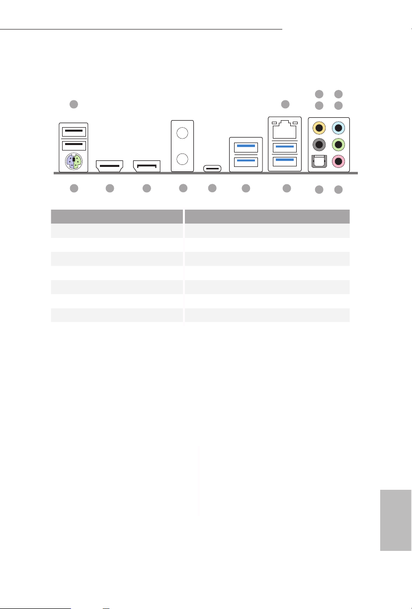
1.4 I/O Panel
1 2
12
15 913
No. Description No. Description
1 USB 2.0 Ports (USB12) 9 USB 3.2 Gen1 Ports (USB3_3_4)
2 2.5G LAN RJ-45 Port* 10 USB 3.2 Gen1 Ports (USB3_1_2)
3 Central / Bass (Orange) 11 USB 3.2 Gen1 Type-C Port (USB3_TC_1)
4 Rear Speaker (Black) 12 Antenna Bracket
5 Line In (Light Blue) 13 DisplayPort 1.4
6 Front Speaker (Lime)** 14 HDMI Port
7 Microphone (Pink) 15 PS/2 Mouse/Keyboard Port
8 Optical SPDIF Out Port
14
11
10
436
5
78
English
9
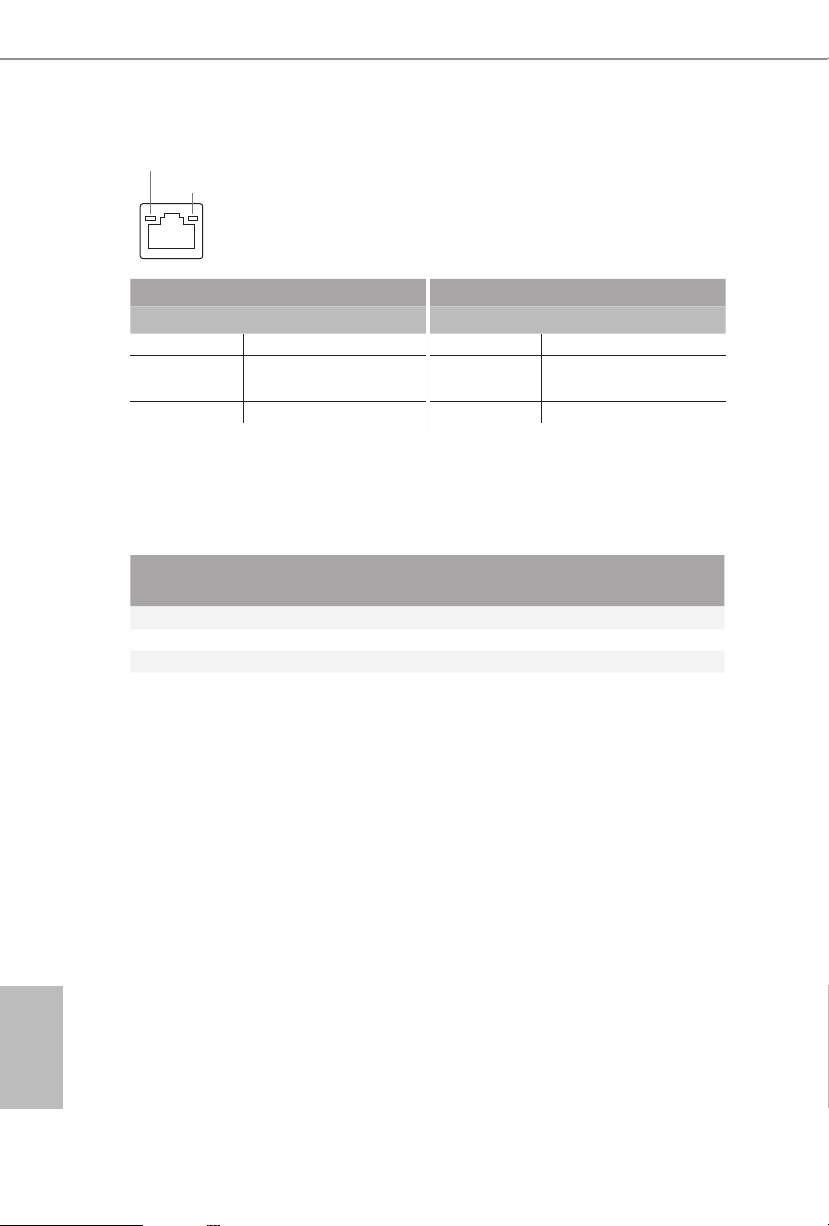
* ere are two LEDs on each LAN port. Please refer to the table below for the LAN port LED indications.
ACT/LINK LED
SPEED LED
LAN Por t
Activity / Link LED Speed LED
Status Description Status Description
O No Link O 10Mbps connection
Blinking Data Activity Orange
100Mbps/1Gbps
connection
On Link Green 2.5Gbps connection
** If you use a 2- channel speaker, plea se connect the speake r’s plug into “Front Spea ker Jack”. See the table below
for connection d etails in accordance w ith the type of speaker you use.
English
Audio Output
Channels
Front Speaker
(No. 6)
Rear Speaker
(No. 4)
Central / Bass
(No. 3)
2 V -- -- --
4 V V -- --
6 V V V --
8 V V V V
Line In
(No. 5)
10

B460M Steel Legend
Chapter 2 Installation
is is a Micro ATX form factor motherboard. Before you install the motherboard,
study the conguration of your chassis to ensure that the motherboard ts into it.
Pre-installation Precautions
Take note of the following precautions before you install motherboard components
or change any motherboard settings.
Make sure to unplug the power cord before installing or removing the motherboard
•
components. Failure to do so may cause physical injuries and damages to motherboard
components.
In order to avoid damage from static electricity to the motherboard’s components,
•
NEVER place your motherboard directly on a carpet. Also remember to use a grounded
wrist strap or touch a safety grounded object before you handle the components.
Hold components by the edges and do not touch the ICs.
•
Whenever you uninstall any components, place them on a grounded anti-static pad or
•
in the bag that comes with the components.
When placing screws to secure the motherboard to the chassis, please do not over-
•
tighten the screws! Doing so may damage the motherboard.
11
English
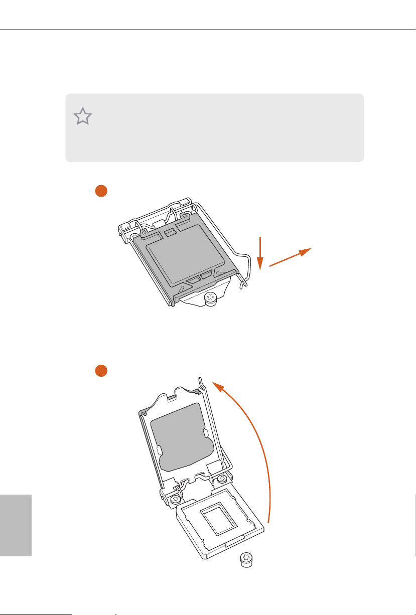
2.1 Installing the CPU
1
1. Before you insert the 1200-Pin CPU into the socke t, please check if the Pn P cap is on the
socket, if the CPU surface is unclean, or if there are any bent pins in the sock et. Do not
force to in sert the CPU into the socket if above situation is found . Otherwise, the CPU
will be seriously damaged.
2. Unplug all power c ables before in stalling the CPU.
English
A
B
2
12
B460M Steel Legend
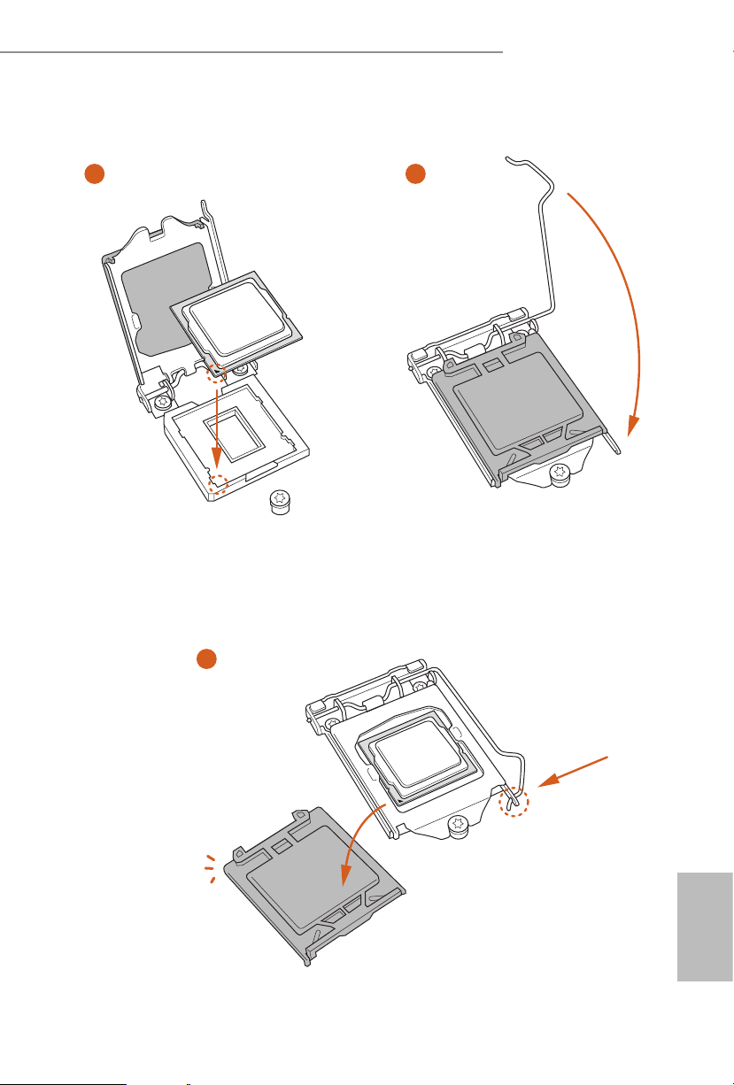
3
5
4
13
English

Please save and replace the cover if the processor i s removed. e cover must be placed if
you wish to return the motherboard for aer service.
English
14
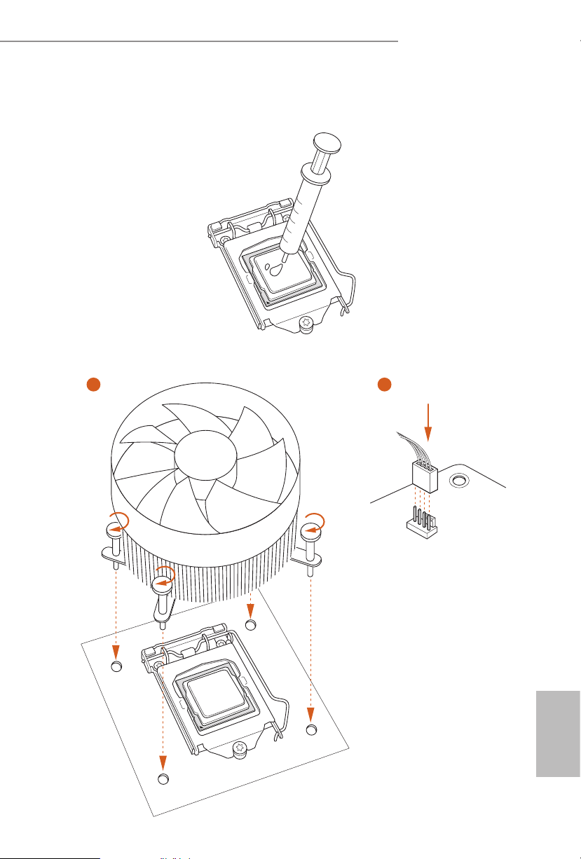
2.2 Installing the CPU Fan and Heatsink
1 2
B460M Steel Legend
CPU_FAN
English
15
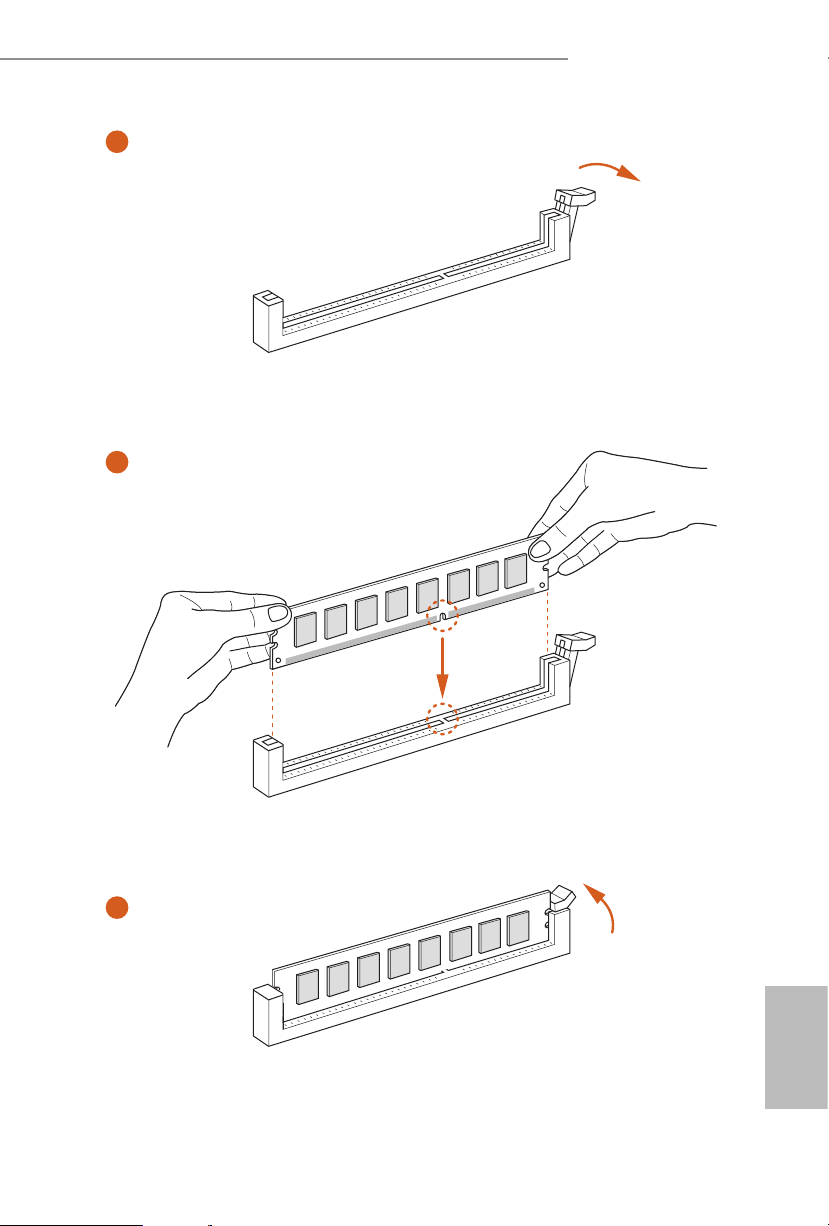
2.3 Installing Memory Modules (DIMM)
is motherboard provides four 288-pin DDR4 (Double Data Rate 4) DIMM slots,
and supports Dual Channel Memory Technology.
1. For dual channe l conguration, you always need to install identical (the same
brand, speed , size and chip-type) DDR4 DIMM pairs.
2. It is unable to activate Dual Channel Memor y Technology with only one or three
memory module installed.
3. It is not allowed to install a DDR, DDR2 or DDR3 memory module into a DDR4
slot; otherwise, this motherboard and DIMM may be damaged.
Dual Channel Memory Conguration
Priority DDR4_A1 DDR4_A2 DDR4_B1 DDR4_B2
1 Populated Populated
2 Populated Populated Populated Populated
e DIMM only ts in one correct orie ntation. It will cause permanent dam age to
the motherboard and the DIMM if you force the DIMM into the slot at incor rect
orientation.
English
16
B460M Steel Legend
1
2
3
English
17
2.4 Expansion Slots (PCI Express Slots)
ere are 3 PCI Express slots on the motherboard.
Before installing an ex pansion card, please make sure that the power supply is
switched o or the power cord is unplugged. Plea se read the documentation of the
expan sion card and mak e necessary h ardware settings for the card before you start
the installation.
PCIe slots:
PCIE1 (PCIe 3.0 x16 slot) is used for PCI Express x16 lane width graphics cards.
PCIE2 (PCIe 3.0 x1 slot) is used for PCI Express x1 lane width cards.
PCIE3 (PCIe 3.0 x16 slot) is used for PCI Express x4 lane width graphics cards.
PCIe Slot Congurations
PCIE1 PCIE3
Single Graphics Card x16 N /A
English
18
Two Graphics Cards in
CrossFireXTM Mode
For a better ther mal environme nt, ple ase connect a ch assis fan to the motherboard’s
chassis fan connector (CHA_ FAN1/WP, CHA_ FAN2/WP, CHA_FAN3/WP or
CHA_ FAN4/WP) when using multiple graphics cards.
x16 x4
B460M Steel Legend
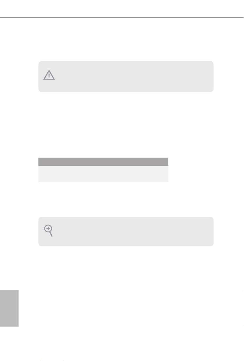
2.5 Jumpers Setup
e illustration shows how jumpers are setup. When the jumper cap is placed on
the pins, the jumper is “Short”. If no jumper cap is placed on the pins, the jumper is
“O pen”.
Clear CMOS Jumper
(CLRMO S1)
(see p.7, No. 22)
CLRMOS1 allows you to clear the data in CMOS. To clear and reset the system
parameters to default setup, please turn o the computer and unplug the power
cord from the power supply. Aer waiting for 15 seconds, use a jumper cap to
short the pins on CLR MOS1 for 5 seconds. However, please do not clear the
CMOS right aer you update the BIOS. If you need to clear the CMOS when you
just nish updating the BIOS, you must boot up the system rst, and then shut it
down before you do the clear-CMOS action. Please be noted that the password,
date, time, and user default prole will be cleared only if the CMOS battery is
removed. Please remember toremove the jumper cap aer clearing the CMOS.
2-pin Jumper
If you clear the CMOS, the case open may be detec ted. Please a djust the BIOS option
“Clear Status” to clear the record of previou s chassis int rusion status.
English
19
2.6 Onboard Headers and Connectors
1
+5V
DUMMY
SIGNAL
GND
DUMMY
SPEAKER
DUMMY
1
Onboard headers and connectors are NOT jump ers. Do NOT place jumper caps over
these headers and connectors. Placing jumper caps over the headers and connectors
will cause permanent damage to the motherboard.
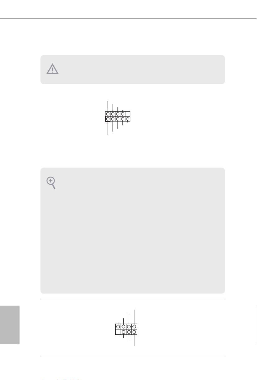
System Panel Header
(9-pi n PANEL1)
(see p.7, No. 16)
PWRBTN (Power Switch):
Connec t to the power switch on the ch assi s front panel. You may congure the way to
turn o your system using the power switch.
RESET (Reset Switch):
Connec t to the reset switch on the chassi s front panel. Press the reset sw itch to restart
the computer if the compute r freezes and fails to perform a norm al restart.
PLED (Syste m Power LED):
Connec t to the power status indicator on the chas sis front panel. e LED i s on when
the system is ope rating. e LED keeps blinking when the system i s in S1/S3 sleep
state. e LED is o when the system is in S4 sleep state or powered o (S5).
HDLED (Ha rd Drive Activity LED):
Connec t to the hard drive ac tivity LED on the chassis front panel. e LED is on
when the hard drive i s reading or writing data.
e front panel de sign may dier by chassis. A front panel module mainly consists
of power s witch , reset switch, power LED, hard dr ive activity LED, speak er and etc.
When connect ing your chassis front panel module to this head er, make sure the wire
assig nments and the pin assig nments are matched correctly.
PLED+
PLED-
HDLED-
HDLED+
PWRBTN#
GND
RESET#
GND
GND
Connect the power
switch, reset switch and
system status indicator on
the chassis to this header
according to the pin
assignments below. Note
the positive and negative
pins before connecting
the cables.
English
20
Chassis Intrusion and
Speaker Header
(7-pi n SPK _CI1)
(see p.7, No. 15)
Please connect the
chassis intrusion and the
chassis speaker to this
header.
B460M Steel Legend
DUMMY
GND
GND
P+
P-
USB_PWR
P+
P-
USB_PWR
1
J_SENSE
OUT2_L
1
MIC_RET
PRESENCE#
GND
OUT2_R
MIC2_R
MIC2_L
OUT_RET
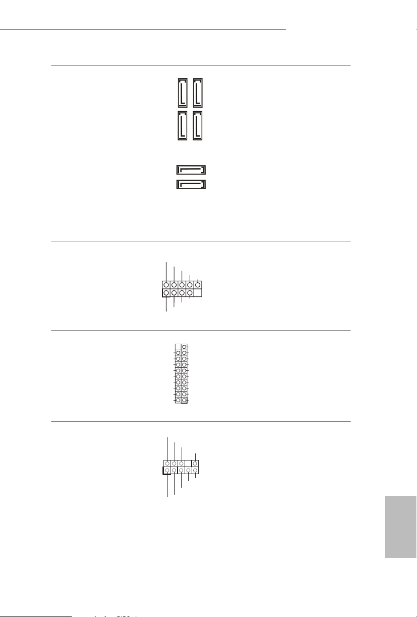
Serial ATA3 Connectors
(SATA3_0:
see p.7, No. 17)
(SATA3_1:
see p.7, No. 18)
(SATA3_ 2:
see p.7, No. 9)
(SATA3_ 3:
see p.7, No. 10)
(SATA3_4:
see p.7, No. 11)
(SATA3_ 5:
see p.7, No. 12)
USB 2.0 Headers
(9-pin USB3_4)
(see p.7, No. 21)
(9-pin USB5_6)
(see p.7, No. 20)
USB 3.2 Gen1 Header
(19-pin USB3_5_6)
(see p.7, No. 8)
IntA_PA_SSRX-
IntA_PA_SSRX+
IntA_PA_SSTX-
IntA_PA_SSTX+
IntA_PA_D-
IntA_PA_D+
SATA3_2
SATA3_4
Vbus
GND
GND
SATA3_1
SATA3_0
VbusVbus
IntA_PB_SSRX-
IntA_PB_SSRX+
GND
IntA_PB_SSTX-
IntA_PB_SSTX+
GND
IntA_PB_D-
IntA_PB_D+
Dummy
1
ese six SATA3
connectors support SATA
SATA3_3
data cables for internal
storage devices with up to
6.0 Gb/s data transfer rate.
SATA3_5
If M2_2 is occupied by a
SATA-type M.2 device,
SATA3_0 will be disabled.
ere are two USB
2.0 headers on this
motherboard.Each USB
2.0 header can support
two ports.
ere is one USB 3.2
Gen1 header on this
motherboard. is USB
3.2 Gen1 header can
support two ports.
Front Panel Audio Header
(9-pin HD_ AUDIO1)
(see p.7, No. 28)
is header is for
connecting audio devices
to the front audio panel.
English
21
1. High De nition Audio supports Jack Sen sing, but the panel wire on the chassis
GND
1
GND
4 3 2 1
FAN_SPEED_CONTROL
1 2 3 4
FAN_SPEED_CONTROL
1 2 3 4
must support HDA to function cor rectly. Please follow the instr uctions in our
manual and chassis manual to in stall your system.
2. If you use an AC’97 audio panel , please inst all it to the front panel audio header by
the steps below:
A. Connect Mic_IN (MIC) to MIC2_ L.
B. Conne ct Audio_R (RIN) to OUT2_R and Audio_ L (LIN) to OUT2_ L.
C. Connect Ground (GND) to Ground (GND).
D. MIC_ RET and OUT_RET are for the HD audio panel only. You don’t ne ed to
connec t them for the AC’97 audio panel.
E. To activate the front mic, go to the “FrontMic” Tab in the Realtek Control panel
and adjust “Recording Volume”.
English
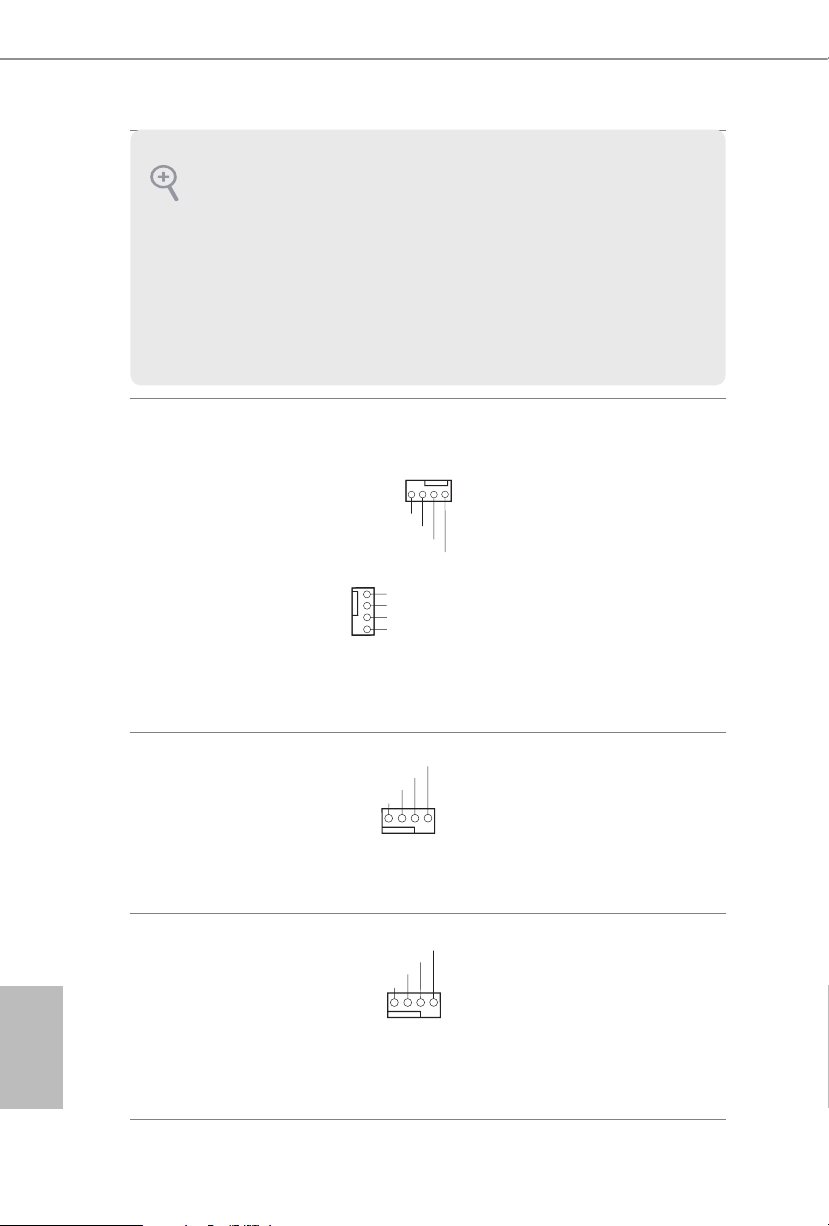
Chassis/Water Pump Fan
Connectors
(4-pin CHA_FAN1/WP)
(see p.7, No. 23)
(4-pin CHA_FAN2/WP)
(see p.7, No. 24)
(4-pin CHA_FAN3/WP)
(see p.7, No. 13)
(4-pin CHA_FAN4/WP)
(see p.7, No. 14)
CPU Fan Connector
(4-pin CPU_FAN1)
(see p.7, No. 3)
CPU/Water Pump Fan
Connector
(4-pin CPU_FAN2/WP)
(see p.7, No. 2)
FAN_SPEED_CONTROL
CHA_FAN_SPEED
FAN_VOLTAGE
FAN_VOLTAGE
2
CHA_FAN_SPEED
3
FAN_SPEED_CONTROL
4
CPU_FAN_SPEED
FAN_VOLTAGE
GND
CPU_FAN_SPEED
FAN_VOLTAGE
GND
is motherboard
provides four 4-Pin water
cooling
chassis
fan
connectors. If you plan to
connect a 3-Pin
chassis
water cooler fan, please
connect it to Pin 1-3.
is motherboard pro-
vides a 4-Pin CPU fan
(Quiet Fan) connector.
If you plan to connect a
3-Pin CPU fan, please
connect it to Pin 1-3.
is motherboard
provides a 4-Pin water
cooling CPU fan
connector. If you plan
to connect a 3-Pin CPU
water cooler fan, please
connect it to Pin 1-3.
22
B460M Steel Legend
4
1
8 5
1
1
SPI_DQ3
#
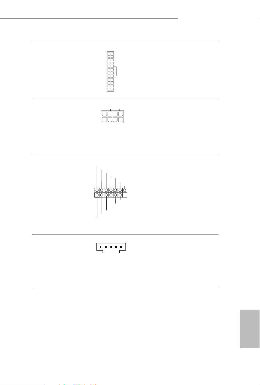
ATX Power Connector
(24-p i n ATX PWR1)
(see p.7, No. 7)
ATX 12V Power
Connector
(8-pin ATX12V1)
(see p.7, No. 1)
SPI TPM Header
(13 -pi n SPI_T PM _J1)
(see p.7, No. 19)
12
1
+3.3V
SPI_CS0
SPI_DQ2
Dummy
CLK
RSMRST#
SPI_MISO
24
13
SPI_MOSI
RST#
SPI_TPM_CS
GND
TPM_PIRQ
is motherboard pro-
vides a 24-pin ATX power
connector. To use a 20-pin
ATX power supply, please
plug it along Pin 1 and Pin
13.
is motherboard pro-
vides a 8-pin ATX 12V
power connector. To use a
4-pin ATX power supply,
please plug it along Pin 1
and Pin 5.
is connector supports SPI
Trusted Platform Module (TPM)
system, which can securely
store keys, digital certicates,
passwords, and data. A TPM
system also helps enhance
network securit y, protects digital
identities, and ensures platform
integrity.
underbolt AIC
Connector
(5-pin TB1)
(see p.7, No. 25)
Please connect a underbolt™
add-in card (AIC) to this
connector via the GPIO cable.
*Please install the underbolt™
AIC card to PCIE3 (default slot).
English
23
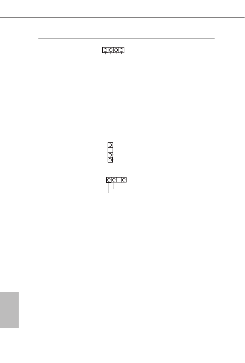
RGB LED Header
1
DO_ADDR
D
1
(4-p i n RGB_LED1)
(see p.7, No. 26)
12V GRB
RGB LED header is used to
connect RGB LED extension
cables which allow users to
choose from various LED light-
ing eects.
Caution: Never install the RGB
LED cable in the wrong orienta-
tion; otherwise, the cable may
be damaged.
*Please refer to page 49 for for
further instructions on this
header.
English
Addressable LED Header
(3-pin A DDR_LE D1)
(see p.7, No. 6)
(3-pin A DDR_LE D2)
(see p.7, No. 27)
1
VOUT
GND
VOUT
DO_ADDR
e headers are used to connect
Addressable
LED extension ca-
bles which allow users to choose
from various LED lighting
eects.
Caution: Never install the
GN
Addressable LED cable in the
wrong orientation; otherwise,
the cable may be damaged.
*Please refer to page 50 for
further instructions on this
header.
24
 Loading...