

User Manual

Version 1.1
Published October 2014
Copyright©2014 ASRock INC. All rights reserved.
Copyright Notice:
No part of this documentation may be reproduced, transcribed, transmitted, or
translated in any language, in any form or by any means, except duplication of
documentation by the purchaser for backup purpose, without written consent of
ASRock Inc.
Products and corporate names appearing in this documentation may or may not
be registered trademarks or copyrights of their respective companies, and are used
only for identication or explanation and to the owners’ benet, without intent to
infringe.
Disclaimer:
Specications and information contained in this documentation are furnished for
informational use only and subject to change without notice, and should not be
constructed as a commitment by ASRock. ASRock assumes no responsibility for
any errors or omissions that may appear in this documentation.
With respect to the contents of this documentation, ASRock does not provide
warranty of any kind, either expressed or implied, including but not limited to
the implied warranties or conditions of merchantability or tness for a particular
purpose.
In no event shall ASRock, its directors, ocers, employees, or agents be liable for
any indirect, special, incidental, or consequential damages (including damages for
loss of prots, loss of business, loss of data, interruption of business and the like),
even if ASRock has been advised of the possibility of such damages arising from any
defect or error in the documentation or product.
e terms HDMI™ and HDMI High-Denition Multimedia Interface, and the HDMI
logo are trademarks or registered trademarks of HDMI Licensing LLC in the United
States and other countries.
is device complies with Part 15 of the FCC Rules. Operation is subject to the following
two conditions:
(1) this device may not cause harmful interference, and
(2) this device must accept any interference received, including interference that
may cause undesired operation.
CALIFORNIA, USA ONLY
e Lithium battery adopted on this motherboard contains Perchlorate, a toxic substance
controlled in Perchlorate Best Management Practices (BMP) regulations passed by the
California Legislature. When you discard the Lithium battery in California, USA, please
follow the related regulations in advance.
“Perchlorate Material-special handling may apply, see
www.dtsc.ca.gov/hazardouswaste/perchlorate”
ASRock Website: http://www.asrock.com

Contents
Chapter 1 Introduction 1
1.1 Package Contents 1
1.2 Specications 2
1.3 Unique Features 6
1.4 Motherboard Layout 10
1.5 I/O Panel 12
Chapter 2 Installation 14
2.1 Installing the CPU 15
2.2 Installing the CPU Fan and Heatsink 17
2.3 Installing Memory Modules (DIMM) 18
2.4 Expansion Slots (PCI Express Slots) 20
2.5 Jumpers Setup 21
2.6 Onboard Headers and Connectors 22
Chapter 3 Software and Utilities Operation 26
3.1 Installing Drivers 26
3.2 A-Tuning 27
3.3 Start8 30
Chapter 4 UEFI SETUP UTILITY 33
4.1 Introduction 33
4.1.1 UEFI Menu Bar 33
4.1.2 Navigation Keys 34
4.2 Main Screen 35

4.3 OC Tweaker Screen 36
4.4 Advanced Screen 39
4.4.1 CPU Conguration 40
4.4.2 Chipset Conguration 41
4.4.3 Storage Conguration 43
4.4.4 Super IO Conguration 44
4.4.5 ACPI Conguration 45
4.4.6 USB Conguration 47
4.4.7 Trusted Computing 48
4.5 Tools 49
4.6 Hardware Health Event Monitoring Screen 52
4.7 Boot Screen 53
4.8 Security Screen 56
4.9 Exit Screen 57

Chapter 1 Introduction
ank you for purchasing ASRock AM1H-ITX motherboard, a reliable
motherboard produced under ASRock’s consistently stringent quality control.
It delivers excellent performance with robust design conforming to ASRock’s
commitment to quality and endurance.
In this manual, Chapter 1 and 2 contains the introduction of the motherboard
and step-by-step installation guides. Chapter 3 contains the operation guide of the
soware and utilities. Chapter 4 contains the conguration guide of the BIOS setup.
Becau se the motherboard specications and the BIOS soware might be updated, the
content of this manual will be subject to change without notice. In ca se any modications of this manual occur, the updated version will be available on ASRock’s website
without further notice. If you require technical suppor t related to this motherboard,
please visit our website for spe cic information about the model you are using. You
may nd the l atest VGA cards and CPU support list on ASRock ’s website a s well.
ASRock website http://www.a srock .com.
1.1 Package Contents
ASRock AM1H-ITX Motherboard (Mini-ITX Form Factor)
•
ASRock AM1H-ITX Quick Insta llation Guide
•
ASRock AM1H-ITX Support CD
•
2 x Serial ATA (SATA) Data Cables (Optional)
•
1 x Serial ATA (SATA) Power Cable (Optional)
•
1 x WiFi Module Screw
•
1 x I/O Panel Shield
•
AM1H-ITX
English
1

English
1.2 Specications
Platform
CPU
Memory
Expansion
Slot
Graphics
•
•
•
•
•
•
•
•
* Due to the power limitation and PCIe bandwidth (x4), the
VGA card is not supported.
•
•
•
•
•
•
•
•
•
•
•
Mini-ITX Form Factor
All Solid Capacitor design
Supports AMD AM1 Socket A-series and E-series Quad-
Core/Dual-Core APU up to 25W
2 x DDR3 DIMM Slots
Supports DDR3 1600/1333/1066 non-ECC, un-buered
memory
Max. capacity of system memory: 32GB (see CAUTION1)
1 x PCI Express 2.0 x16 Slot (PCIE1 @ x4 mode)
1 x mini-PCI Express Slot
Integrated AMD RadeonTM R3 Series Graphics in A-series /
E-series APU
DirectX 11.1, Pixel Shader 5.0
Max. shared memory 2GB
Four graphics output options: D-Sub, DVI-D, HDMI and
DisplayPort 1.2 (see CAUTION2)
Supports HDMI with max. resolution up to 4K × 2K
(4096x2160) @ 24Hz or 4K × 2K (3840x2160) @ 30Hz
Supports DVI-D with ma x. resolution up to 1920x1200 @
60Hz
Supports D-Sub with max. resolution up to 2048x1536 @
60Hz
Supports DisplayPort 1.2 with max. resolution up to 4K × 2K
(4096x2160) @ 30Hz
Supports Auto Lip Sync, Deep Color (12bpc), xvYCC and
HBR (High Bit Rate Audio) with HDMI Port (Compliant
HDMI monitor is required)
Supports HDCP with DVI-D, HDMI and DisplayPort 1.2
Ports
Supports Full HD 1080p Blu-ray (BD) playback with DVI-D,
HDMI and DisplayPort 1.2 Ports
2

Audio
LAN
Rear Panel
I/O
7.1 CH HD Audio with Content Protection (Realtek ALC892
•
Audio Codec)
Premium Blu-ray Audio support
•
Supports Full Spike Protection
•
PCIE x1 Gigabit LAN 10/100/1000 Mb/s
•
Realtek RTL8111GR
•
Supports Realtek RealWoW! Technolog y
•
Supports Wake-On-LAN
•
Supports Full Spike Protection
•
Supports LAN Cable Detection
•
Supports Energy Ecient Ethernet 802.3az
•
Supports PXE
•
1 x DC Jack
•
1 x PS/2 Mouse/Keyboard Port
•
1 x D-Sub Port
•
1 x DVI-D Port
•
1 x HDMI Port
•
1 x DisplayPort 1.2
•
1 x Optica l SPDIF Out Port
•
2 x USB 2.0 Ports (Supports Full Spike Protection)
•
2 x USB 3.0 Ports (Supports Full Spike Protection)
•
1 x RJ-45 LAN Port with LED (ACT/LINK LED and SPEED
•
LED)
HD Audio Jacks: Rear Speaker / Central / Bass / Line in /
•
Front Speaker / Microphone
AM1H-ITX
Storage
2 x SATA3 6.0 Gb/s Connectors by AMD AM1 Series Socket
•
25W Quad-Core APU, support NCQ, AHCI and Hot Plug
2 x SATA3 6.0 Gb/s Connectors by ASMedia ASM1061, sup-
•
port NCQ, AHCI and Hot Plug
English
3

Connector
BIOS
Feature
Support
CD
1 x COM Port Header
•
1 x Chassis Intrusion Header
•
1 x TPM Header
•
1 x CPU Fan Connector (4-pin)
•
1 x Chassis Fan Connector (4-pin)
•
1 x Power Fan Connector (3-pin)
•
1 x 24 pin ATX Power Connector
•
1 x SATA Power Connector
•
1 x Front Panel Audio Connector
•
2 x USB 2.0 Headers (Support 4 USB 2.0 ports) (Supports Full
•
Spike Protection)
1 x USB 3.0 Header by ASMedia ASM1042A (Supports 2 USB
•
3.0 ports) (Supports Full Spike Protection)
32Mb AMI UEFI Legal BIOS with GUI support
•
Supports “Plug and Play”
•
ACPI 1.1 compliance wake up events
•
Supports jumperfree
•
SMBIOS 2.3.1 support
•
DRAM Voltage multi-adjustment
•
Drivers, Utilities, AntiVirus Soware (Tria l Version), Google
•
Chrome Browser and Toolbar, Start8 (30 days trial)
English
4
CPU/Chassis temperature sensing
Hardware
Monitor
OS
Certications
* For detailed product information, please visit our website: http://ww w.asrock.com
•
CPU/Chassis/Power Fan Tachometer
•
CPU Quiet Fan
•
CPU Fan multi-speed control
•
CASE OPEN detection
•
Voltage monitoring: +12V, +5V, +3.3V, Vcore
•
Microso® Windows® 8.1 32-bit / 8.1 64-bit / 8 32-bit / 8 64-
•
bit / 7 32-bit / 7 64-bit / XP 32-bit / XP 64-bit
FCC, CE, WHQL
•
ErP/EuP ready (ErP/EuP ready power supply is required)
•

Please realize that the re is a certain r isk involved with overclo cking, including adju sting the setting in the BIOS, applying Untied Ove rclocking Technology, or using thirdparty o verclocking tools. Overclocking may aect your system’s stability, or even c ause
damage to the components and dev ices of your system. It should be done at your own
risk and expense. We are not responsible for possible damage cau sed by overclocking.
1. Due to the operating system limitation, the actual memory size may be less than 4GB
for the reservation for system usage under Windows® 8 / 7 / XP. For Windows® 64-bit
OS with 64-bit CPU, there is no such limitation. You can use ASRock XFast RAM to
utilize the memory that Windows® cannot use.
2. HDMI and DisplayPort 1.2 cannot output at the same time . You can only cho ose
either one of them. Plea se refer to the BIOS setup option “HDMI/DP Switch“ on
page 42.
AM1H-ITX
English
5

1.3 Unique Features
ASRock A-Tuning
A-Tuning is ASRock’s multi purpose soware suite with a new interface, more new
features and improved utilities, including XFast R AM, Dehumidier, Good Night
LED, FAN-Tastic Tuning and a whole lot more.
ASRock Instant Boot
ASRock Instant Boot allows you to turn on your PC in just a few seconds, provides a
much more ecient way to save energy, time, money, and improves system running
speed for your system. It leverages the S3 and S4 ACPI features which normally
enable the Sleep/Standby and Hibernation modes in Windows® to shorten boot
up time. By calling S3 and S4 at specic timing during the shutdown and startup
process, Instant Boot allows you to enter your Windows® desktop in a few seconds.
ASRock Instant Flash
ASRock Instant Flash is a BIOS ash utility embedded in Flash ROM. is conve-
nient BIOS update tool allows you to update the system BIOS in a few clicks without
preparing an additional oppy diskette or other complicated ash utility. Just save
the new BIOS le to your USB storage and launch this tool by pressing <F6> or
<F2> during POST to enter the BIOS setup menu to access ASRock Instant Flash.
Please be noted that the USB ash drive or hard drive must use FAT32/16/12 le
system.
ASRock APP Charger
Simply by installing the ASRock APP Charger makes your iPhone/iPad/iPod Touch
charge up to 40% faster than before on your computer. ASRock APP Charger allows
you to quickly charge many Apple devices simultaneously and even supports
continuous charging when your PC enters into Suspend to RAM (S3), hibernation
mode (S4) or power o (S5).
English
6
ASRock XFast LAN
ASRock XFast LAN provides faster internet access, which includes the benets
listed below. LAN Application Prioritization: You can congure your application’s
priority ideally and add new programs to the list. Lower Latency in Game: Aer
setting online game’s priority higher, it can lower the latency in games. Trac
Shaping: You can watch Youtube HD videos and download simultaneously. Real-
Time Analysis of Your Data: With the status window, you can easily recognize
which data streams you are currently transferring.

ASRock XFast RAM
ASRock XFast RAM is included in A-Tuning. It fully utilizes the memory space
that cannot be used under Windows® 32-bit operating systems. ASRock XFast RAM
shortens the loading time of previously visited websites, making web surng faster
than ever. And it also boosts the speed of Adobe Photoshop 5 times faster. Another
advantage of ASRock XFast RAM is that it reduces the frequency of accessing your
SSDs or HDDs in order to extend their lifespan.
ASRock Crashless BIOS
ASRock Crashless BIOS allows users to update their BIOS without fear of failing. If
power loss occurs during the BIOS updating process, ASRock Crashless BIOS will
automatically nish the BIOS update procedure aer regaining power. Please note
that BIOS les need to be placed in the root directory of your USB disk. Only USB 2.0
ports support this feature.
ASRock OMG (Online Management Guard)
Administrators are able to establish an internet curfew or restrict internet access
at specied times via OMG. You may schedule the starting and ending hours of
internet access granted to other users. In order to prevent users from bypassing
OMG, guest accounts without permission to modify the system time are required.
AM1H-ITX
ASRock Internet Flash
ASRock Internet Flash downloads and updates the latest UEFI rmware version
from our servers for you without entering Windows® OS. Please setup network
conguration before using Internet Flash.
ASRock UEFI Tech Service
Contact ASRock Tech Service by sending a support request from the UEFI setup
utility if you are having trouble with your personal computer. Users may try to
choose the category of the issue they have encountered, describe the problem in
detail, and then attach an optional picture or log le for our technical support team.
ASRock On/O Play Technology
ASRock On/O Play Technology allows users to enjoy the great audio experience
from the portable audio devices, such like MP3 player or mobile phone to your
PC, even when the PC is turned o (or in ACPI S5 mode)! is motherboard also
provides a free 3.5mm audio cable (optional) that ensures users the most convenient
computing environment.
English
7
ASRock Dehumidier Function
Users may prevent motherboard damages due to dampness by enabling
“Dehumidier Function”. When enabling Dehumidier Function, the computer
will power on automatically to dehumidify the system aer entering S4/S5 state.
ASRock Easy Driver Installer
For users that don’t have an optical disk drive to install the drivers from our support
CD, Easy Driver Installer is a handy tool in the UEFI that installs the LAN driver
to your system via an USB storage device, then downloads and installs the other
required drivers automatically.
ASRock Interactive UEFI
ASRock Interactive UEFI is a blend of system conguration tools, cool sound eects
and stunning visuals. e unprecedented UEFI provides a more attractive interface
and more amusment.
ASRock Fast Boot
With ASRock’s exclusive Fast Boot technolog y, it takes less than 1.5 seconds to
logon to Windows 8 from a cold boot. No more waiting! e speedy boot will
completely change your user experience and behavior.
ASRock Restart to UEFI
Windows® 8 brings the ultimate boot up experience. e lightning boot up speed
makes it hard to access the UEFI setup. ASRock Restart to UEFI allows users to
enter the UEFI automatically when turning on the PC. By enabling this function,
the PC will enter the UEFI directly aer you restart.
English
8
ASRock USB Key
In a world where time is money, why waste precious time everyday typing
usernames to log in to Windows? Why should we even bother memorizing those
foot long passwords? Just plug in the USB Key and let your computer log in to
windows automatically!
ASRock FAN-Tastic Tuning
ASRock FAN-Tastic Tuning is included in A-Tuning. Congure up to ve dierent
fan speeds using the graph. e fans will automatically shi to the next speed level
when the assigned temperature is met.

ASRock Good Night LED
ASRock Good Night LED technology oers you a better sleeping environment by
extinguishing the unessential LEDs. By enabling Good Night LED in the BIOS, the
Power/LAN LEDs will be switched o when the system is powered on. Good Night
LED will automatically switch o the Power and LAN LEDs when the system enters
into Standby/Hibernation mode as well.
AM1H-ITX
English
9
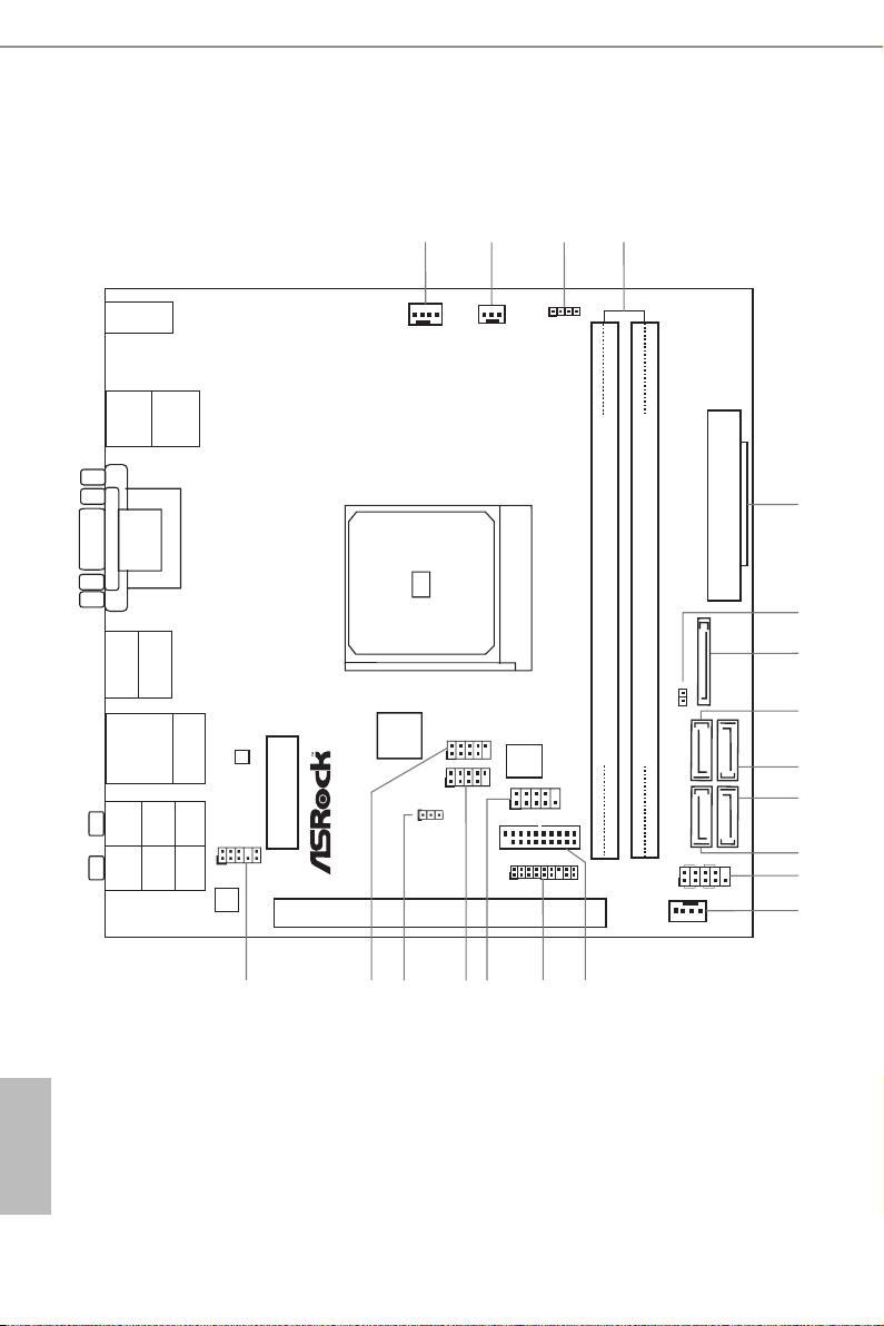
1.4 Motherboard Layout
ATXPW R1
FS B 800
DDR3_A1 (6 4 bit, 240-pin mo du le)
DDR3_A2 (6 4 bit, 240-pin mo du le)
SATA3_1
Sup er
I/O
LAN
AUDIO
CODEC
1
CLRCMO S1
PCIE1
1
USB2_ 3
1
USB4_ 5
HD_AUD IO1
1
CPU_FA N1
CHA_FAN 1
SPEAKE R1
1
HDLED RE SET
PLED PWRBTN
1
PANEL 1
RJ-45 LAN
USB 3 .0
T: U SB0
B: US B1
CI1
1
SOCK ET FS1b
SATA3_2
Fr on t U SB 3. 0
PWR_FAN 1
TPMS1
1
1
COM1
2
3
4
5
1
6
7
8
12
9
10
11
13
14
16
17
18
15
USB 2.0
T: USB 0
B: U SB1
PS2
Key boa rd/
Mou se
USB3_ 2_3
SATA3_A 1
SATA3_A 2
19
MPCIE 1
DC_ JA CK1
DP_1
HDMI
VGA 1
DVI1
Top:
CTR BAS S
Cent er:
REAR SP K
Bott om:
Opti cal
SPDI F
Top:
LINE IN
Cent er:
FRON T
Bott om:
MIC IN
SATA_POW 1
20
Ro HS
English
10
AM 1 H - I T X
32M b
BIO S

No. Description
1 CPU Fan Connector (CPU_FAN1)
2 Power Fan Connector (PWR_FAN1)
3 Chassis Speaker Header (SPEAKER1)
4 2 x 240-pin DDR3 DIMM Slots (DDR3_A1, DDR3_A2)
5 ATX Power Connector (ATXPWR1)
6 Chassis Intrusion Header (CI1)
7 SATA Power Connector (SATA_POW1)
8 SATA3 Connector (SATA3_1)
9 SATA3 Connector (SATA3_2)
10 SATA3 Connector (SATA3_A2)
11 SATA3 Connector (SATA3_A1)
12 System Panel Header (PANEL1)
13 Chassis Fan Connector (CHA_FAN1)
14 USB 3.0 Header (USB3_2_3)
15 TPM Header (TPMS1)
16 COM Port Header (COM1)
17 USB 2.0 Header (USB4_5)
18 Clear CMOS Jumper (CLRCMOS1)
19 USB 2.0 Header (USB2_3)
20 Front Panel Audio Header (HD_AUDIO1)
AM1H-ITX
11
English
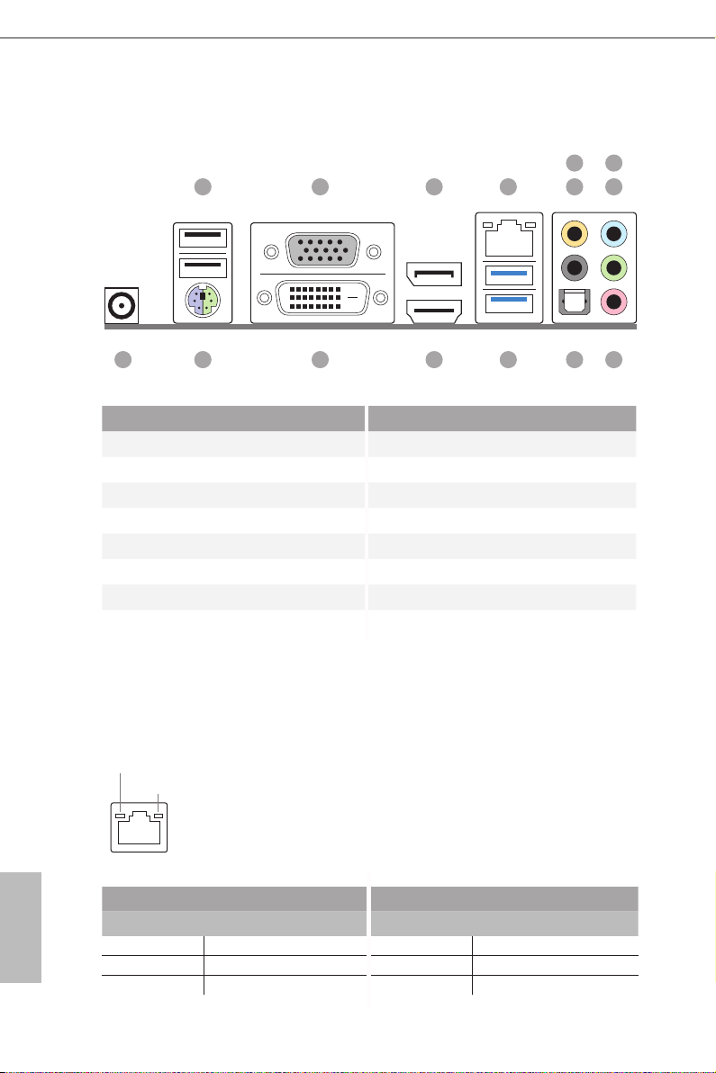
1.5 I/O Panel
1 4
2 3
7
658
15
No. Description No. Description
1 USB 2.0 Ports (USB01) 9 Microphone (Pink)
2 D-Sub Port 10 Optica l SPDIF Out Port
3 DisplayPort 1.2* 11 USB 3.0 Ports (USB3_0_1)
4 LAN RJ-45 Port** 12 HDMI Port*
5 Central / Bass (Orange) 13 DVI-D Port
6 Rear Speaker (Black) 14 PS/2 Mouse/Keyboard Port
7 Line In (Light Blue) 15 DC Jack****
8 Front Speaker (Lime)***
* HDMI and DisplayPort 1.2 cannot output at the same time. You can only choose either one of them . Please refer
to the BIOS setup option “HDMI/DP Switch“ on page 42.
** ere are two LEDs on each LAN port. Please refer to the table below for the LAN port LED indications.
ACT/LINK L ED
SPEED LE D
LAN Por t
1213
1114 910
English
12
Activity / Link LED Speed LED
Status Description Status Description
O No Link O 10Mbps connection
Blinking Data Activity Orange 100Mbps connection
On Link Green 1Gbps connection
AM1H-ITX
*** If you use a 2-channel speaker, please connect the spe aker’s plug into “Front Speaker Jack”. See the table below
for connection d etails in accordance w ith the type of speaker you use.
Audio Output
Channels
Front Speaker
(No. 8)
Rear Speaker
(No. 6)
Central / Bass
(No. 5)
Line In or
Side Speaker
(No. 7)
2 V -- -- --
4 V V -- --
6 V V V --
8 V V V V
To enable Multi-Streaming, you need to connect a front panel audio cable to the front
panel au dio header. Aer re starting your computer, you will nd the “Mixe r” tool
on your system. Pl ease select “Mixer ToolBox” , click “En able playback multistreaming”, and click “ok”. Choose “2CH”, “4CH”, “6CH”, or “8CH” and the n you are
allowe d to sele ct “Realtek HDA Pr imary output ” to use the Rear Speaker, Central/
Bass, and Front Speake r, or select “Realtek HDA Audio 2nd output” to use the front
panel au dio.
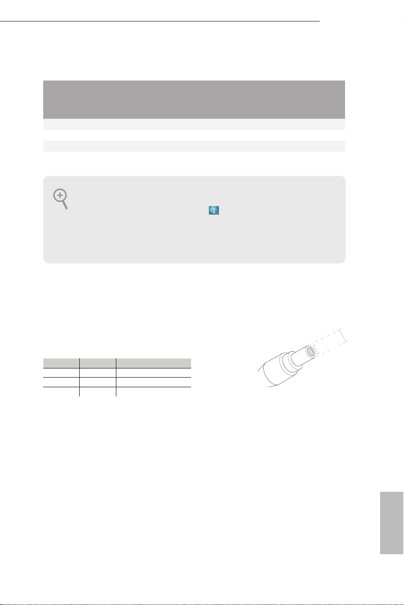
**** Please u se a 19V power adapter for the DC jack. is jack accepts du al barrel plugs with an inne r diameter of
2.5 mm and an outer diameter of 5.5 mm , where the inner contact i s +19V (±10%) DC and the shell is GND.
Please refer to below hardware conguration for the estimated adapter powe r.
DRAM HDD Estimated Adapter Powe r
1 1 41W
1 2 56W
2 2 60W
Due to the power limitation and PCIe bandwidth (x4), the VGA card is not suppor ted.
is motherboard is available with support for either ATX or DC-in power supplies. Pl ease do not use two kinds
of power supplie s at the same time! Doing so may damage the motherboard component s and devices. When you
use the DC-in power adapter, plea se use the onboard S ATA power connector to get the power for HDD s.
2.5 mm
5.5 mm
13
English

Chapter 2 Installation
is is a Mini-ITX form factor motherboard. Before you install the motherboard,
study the conguration of your chassis to ensure that the motherboard ts into it.
Pre-installation Precautions
Take note of the following precautions before you install motherboard components
or change any motherboard settings.
Make sure to unplug the power cord before installing or removing the motherboard.
•
Failure to do so may cause physical injuries to you and damages to motherboard
components.
In order to avoid damage from static electricity to the motherboard’s components,
•
NEVER place your motherboard directly on a carpet. Also remember to use a grounded
wrist strap or touch a safety grounded object before you handle the components.
Hold components by the edges and do not touch the ICs.
•
Whenever you uninstall any components, place them on a grounded anti-static pad or
•
in the bag that comes with the components.
When placing screws to secure the motherboard to the chassis, please do not over-
•
tighten the screws! Doing so may damage the motherboard.
English
14
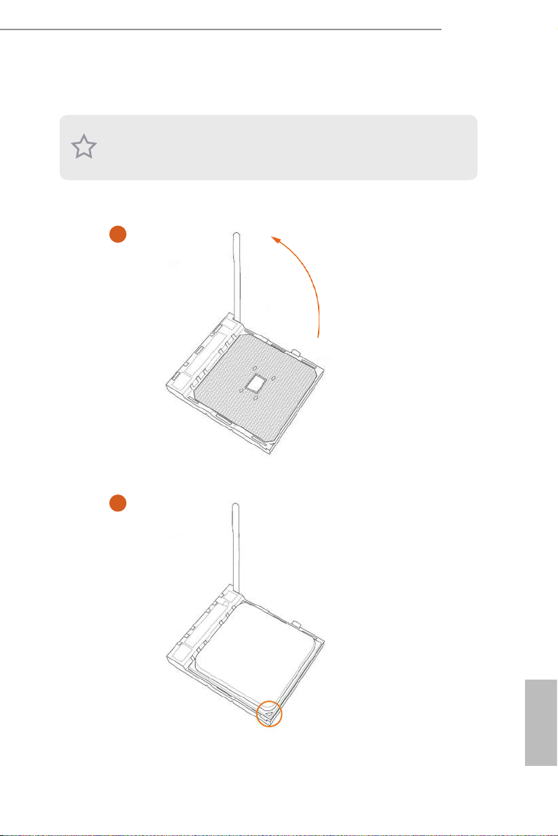
2.1 Installing the CPU
Unplug all power cables be fore installing the CPU.
1
AM1H-ITX
2
English
15
 Loading...