

Page 1
Copyright Notice:Copyright Notice:
Copyright Notice:
Copyright Notice:Copyright Notice:
No part of this installation guide may be reproduced, transcribed, transmitted, or translated in any language, in any form or by any means, except duplication of documentation by the purchaser for backup purpose, without written consent of ASRock Inc.
Products and corporate names appearing in this guide may or may not be registered
trademarks or copyrights of their respective companies, and are used only for identification or explanation and to the owners’ benefit, without intent to infringe.
Disclaimer:Disclaimer:
Disclaimer:
Disclaimer:Disclaimer:
Specifications and information contained in this guide are furnished for informational
use only and subject to change without notice, and should not be constructed as a
commitment by ASRock. ASRock assumes no responsibility for any errors or omissions
that may appear in this guide.
With respect to the contents of this guide, ASRock does not provide warranty of any kind,
either expressed or implied, including but not limited to the implied warranties or
conditions of merchantability or fitness for a particular purpose. In no event shall
ASRock, its directors, officers, employees, or agents be liable for any indirect, special,
incidental, or consequential damages (including damages for loss of profits, loss of
business, loss of data, interruption of business and the like), even if ASRock has been
advised of the possibility of such damages arising from any defect or error in the guide
or product.
This device complies with Part 15 of the FCC Rules. Operation is subject to the
following two conditions:
(1) this device may not cause harmful interference, and
(2) this device must accept any interference received, including interference that
may cause undesired operation.
CALIFORNIA, USA ONLY
The Lithium battery adopted on this motherboard contains Perchlorate, a toxic
substance controlled in Perchlorate Best Management Practices (BMP) regulations
passed by the California Legislature. When you discard the Lithium battery in
California, USA, please follow the related regulations in advance.
“Perchlorate Material-special handling may apply, see
www.dtsc.ca.gov/hazardouswaste/perchlorate”
ASRock Website: http://www.asrock.com
Published November 2007
Copyright©2007 ASRock INC. All rights reserved.
ASRock ALiveNF6P-VSTA Motherboard
EnglishEnglish
EnglishEnglish
English
11
1
11
Page 2
Motherboard LMotherboard L
Motherboard L
Motherboard LMotherboard L
ayoutayout
ayout
ayoutayout
English
EnglishEnglish
EnglishEnglish
22
2
22
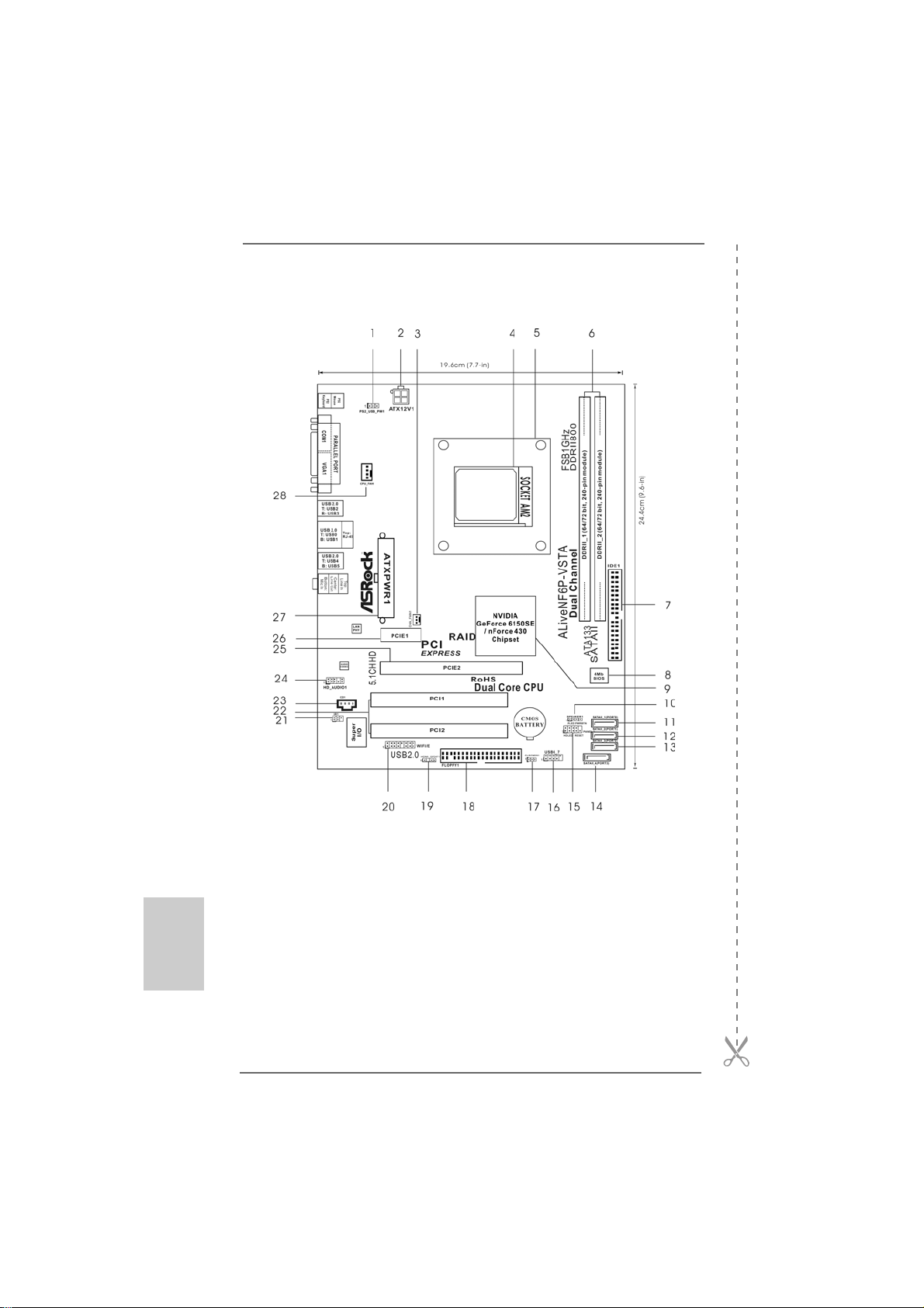
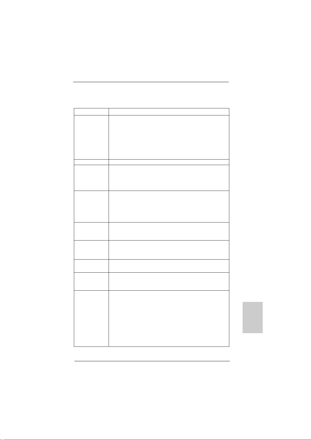
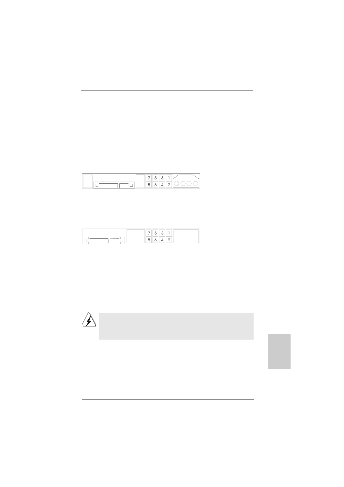
1 PS2_USB_PW1 Jumper 15 System Panel Header (PANEL1)
2 ATX 12V Power Connector (ATX12V1) 16 USB 2.0 Header (USB6_7, Blue)
3 Chassis Fan Connector (CHA_FAN1) 17 Clear CMOS Jumper (CLRCMOS1)
4 AM2 940-Pin CPU Socket 18 Floppy Connector (FLOPPY1)
5 CPU Heatsink Retention Module 19 HDMI_SPDIF Header (HDMI_SPDIF1)
6 2 x 240-pin DDRII DIMM Slots 20 WiFi/E Header (WIFI/E)
(Dual Channe: DDRII_1, DDRII_2; Yellow) 21 DeskExpress Hot Plug Detection Header
7 Primary IDE Connector (IDE1, Blue) (IR1)
8 BIOS SPI Chip 22 PCI Slots (PCI1- 2)
9 NVIDIA GeForce 6150SE / nForce 430 Chipset 23 Internal Audio Connector: CD1 (Black)
10 Chassis Speaker Header (SPEAKER 1) 2 4 Front Panel Audio Header (HD_AUDIO1)
11 SATAII Connector (SATAII_1 (PORT0), Red) 25 PCI Express x16 Slot (PCIE2)
12 SATAII Connector (SATAII_2 (PORT1), Red) 26 PCI Express x1 Slot (PCIE1)
13 SATAII Connector (SATAII_3 (PORT2), Red) 27 ATX Power Connector (ATXPWR1)
14 SATAII Connector (SATAII_4 (PORT3), Red) 28 CPU Fan Connector (CPU_FAN1)
ASRock ALiveNF6P-VSTA Motherboard
Page 3
TMTM
TM
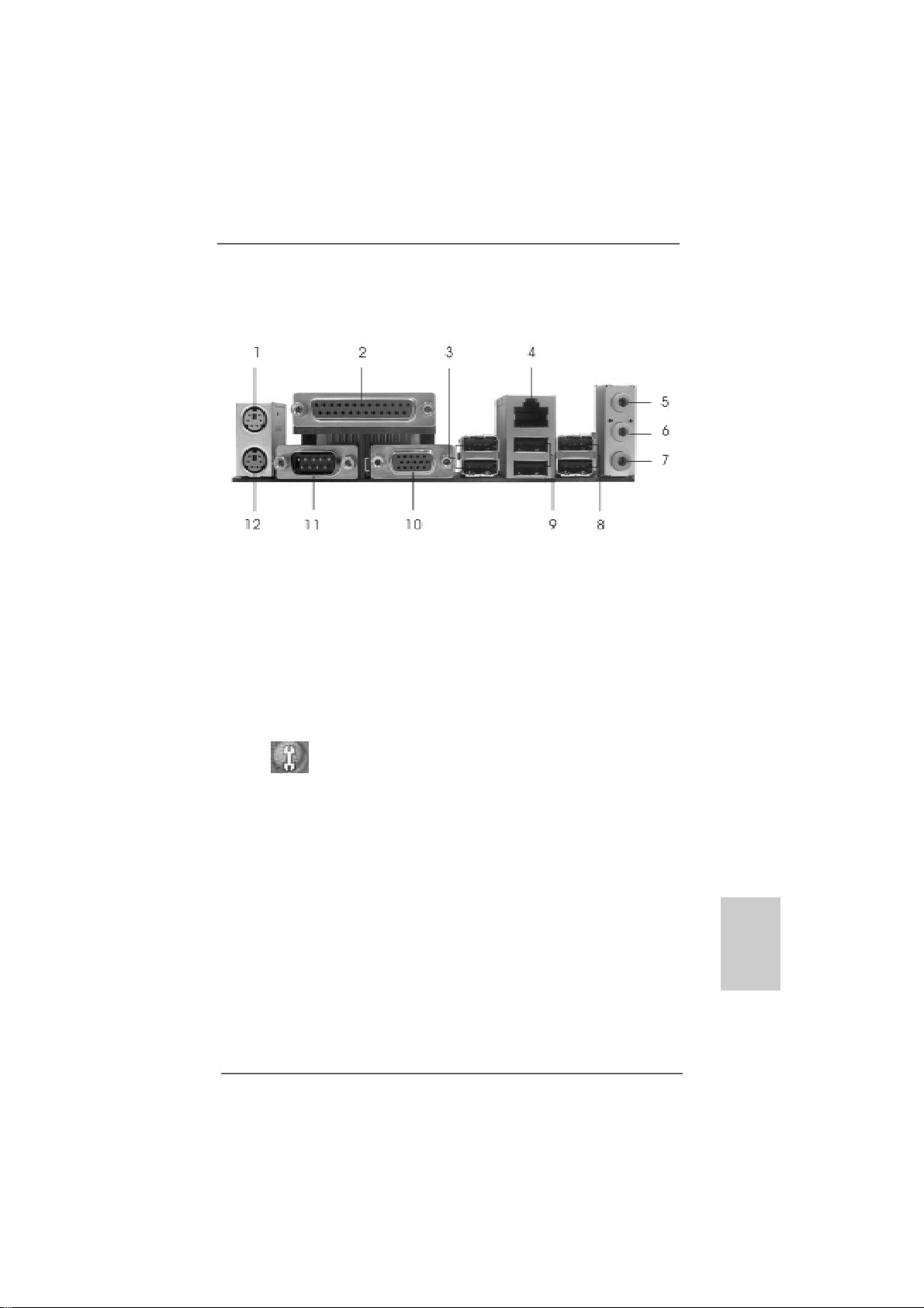
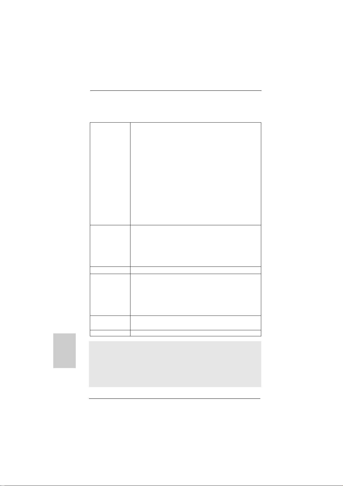
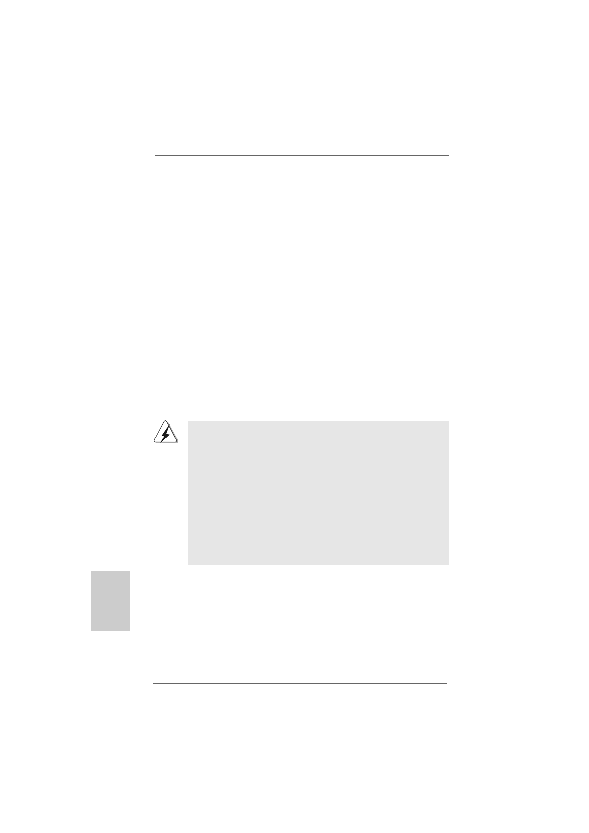
ASRock 6CH I/O PlusASRock 6CH I/O Plus
ASRock 6CH I/O Plus
ASRock 6CH I/O PlusASRock 6CH I/O Plus
1 PS/2 Mouse Port (Green) 7 Microphone (Pink)
2 Parallel Port 8 Shared USB 2.0 Ports (USB45)
3 USB 2.0 Ports (USB23) 9 USB 2.0 Ports (USB01)
4 RJ-45 Port 10 VGA Port
5 Line In (Light Blue) 11 COM Port
6 Line Out (Lime) 12 PS/2 Keyboard Port (Purple)
* To enable Multi-Streaming function, you need to connect a front panel audio cable to the front
panel audio header. Please refer to below steps for the software setting of Multi-Streaming.
For Windows® XP:
After restarting your computer, you will find “Mixer” tool on your system. Please select “Mixer
ToolBox” , click “Enable playback multi-streaming”, and click “ok”. Choose “2CH” or
TMTM
“4CH” and then you are allowed to select “Realtek HDA Primary output” to use Rear Speaker
and Front Speaker, or select “Realtek HDA Audio 2nd output” to use front panel audio. Then
reboot your system.
For Windows® VistaTM:
After restarting your computer, please double-click “Realtek HD Audio Manager” on the
system tray. Set “Speaker Configuration” to “Quadraphonic” or “Stereo”. Click “Device
advanced settings”, choose “Make front and rear output devices playbacks two different audio
streams simultaneously”, and click “ok”. Then reboot your system.
ASRock ALiveNF6P-VSTA Motherboard
EnglishEnglish
EnglishEnglish
English
33
3
33
Page 4
1.1.
IntroductionIntroduction
1.
Introduction
1.1.
IntroductionIntroduction
Thank you for purcha sing ASRock ALiveNF6P-VSTA motherboard, a relia ble motherboard
produced under ASRock’s consistently stringent quality control. It delivers excellent
performance with robust design conforming to ASRock’s commitment to quality and
endurance.
This Quick Installation Guide contains introduction of the motherboard and step-bystep installation guide. More detailed information of the motherboard can be found in
the user manual presented in the Support CD.
Because the motherboard specifications and the BIOS software might
be updated, the content of this manual will be subject to change without
notice. In case any modifications of this manual occur, the updated
version will be available on ASRock website without further notice. You
may find the latest VGA cards and CPU support lists on ASRock website
as well. ASRock website http://www.asrock.com
If you require technical support related to this motherboard, please visit
our website for specific information about the model you are using.
www.asrock.com/support/index.asp
1.11.1
PP
ackack
1.1
1.11.1
1 x ASRock ALiveNF6P-VSTA Motherboard
(Micro ATX Form Factor: 9.6-in x 7.7-in, 24.4 cm x 19.6 cm)
1 x ASRock ALiveNF6P-VSTA Quick Installation Guide
1 x ASRock ALiveNF6P-VSTA Support CD
1 x Ultra A TA 66/100/133 IDE Ribbon Ca ble (80-conductor)
1 x 3.5-in Floppy Drive Ribbon Cable
1 x Serial A TA (SAT A) Data Ca ble (Optional)
1 x Serial AT A (SAT A) HDD Power Cable (Optional)
1 x HDMI_SPDIF Cable (Optional)
1 x “ASRock 6CH I/O Plus” I/O Shield
age Contentsage Contents
P
ack
age Contents
PP
ackack
age Contentsage Contents
English
EnglishEnglish
EnglishEnglish
44
4
44
ASRock ALiveNF6P-VSTA Motherboard
Page 5
1.21.2
SpecificationsSpecifications
1.2
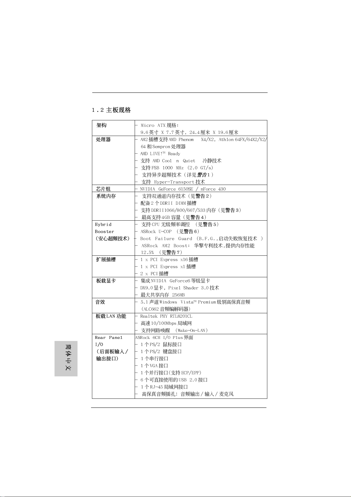
Specifications
1.21.2
SpecificationsSpecifications
Platform - Micro ATX Form Factor: 9.6-in x 7.7-in, 24.4 cm x 19.6 cm
CPU - Socket AM2 for AMD PhenomTM X4 / X2, Athlon 64FX / 64X2 /
X2 / 64 and Sempron Processors
- AMD LIVE!TM Ready
- Supports AMD’s Cool ‘n’ QuietTM T echnology
- FSB 1000 MHz (2.0 GT/s)
- Supports Untied Overclocking Technology (see CAUTION 1)
- Supports Hyper-Tran sport Technology
Chipset - NVIDIA® GeForce 6150SE / nForce 430
Memory - Dual Channel DDRII Memory Technology (see CAUTION 2)
- 2 x DDRII DIMM slots
- Support DDRII1066/800/667/533 (see CAUTION 3)
- Max. capacity: 4GB (see CAUTION 4)
Hybrid Booster - CPU Frequency Stepless Control (see CAUTION 5)
- ASRock U-COP (see CAUTION 6)
- Boot Failure Guard (B.F.G.)
- ASRock AM2 Boost: ASRock Patented Technology to boost
memory performance up to 12.5% (see CAUTION 7)
Expansion Slot - 1 x PCI Express x16 slot
- 1 x PCI Express x1 slot
- 2 x PCI slots
Graphics - Integrated N VIDIA® GeForce6-class gra phics
- D X9.0 VGA, Pixel Shader 3.0
- Max. shared memory 256MB
Audio - 5.1 CH Windows® VistaTM Premium Level HD Audio
(Realtek ALC662 Audio Code c)
LAN - Realtek PHY RTL8201CL
- Speed: 10/100 Ethernet
- Supports Wa ke-On-LAN
Rear Panel I/O ASRock 6CH I/O Plus
- 1 x PS/2 Mouse Port
- 1 x PS/2 Keyboard Port
- 1 x Serial Port: COM1
- 1 x VGA Port
- 1 x Parallel Port (ECP/EPP Support)
- 6 x Ready-to-Use USB 2.0 Ports
- 1 x RJ-45 LAN Port
- HD Audio Jack: Line in / Front Spea ker / Microphone
EnglishEnglish
EnglishEnglish
English
ASRock ALiveNF6P-VSTA Motherboard
55
5
55
Page 6
English
EnglishEnglish
EnglishEnglish
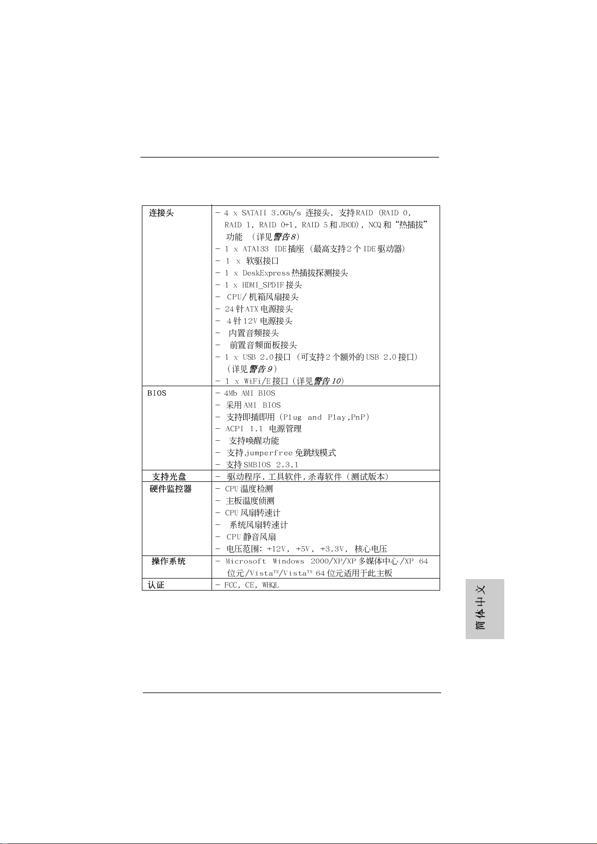
Connector - 4 x Serial AT AII 3.0Gb/s connectors, support RAID (RAID 0,
RAID 1, RAID 0+1, RAID 5 and JBOD), NCQ a nd “Hot Plug”
functions (see CAUTION 8)
- 1 x ATA133 IDE connector (supports 2 x IDE device s)
- 1 x Floppy connector
- 1 x DeskExpre ss Hot Plug Detection header
- 1 x HDMI_SPDIF header
- CPU/Chassis FAN connector
- 24 pin A TX power conne ctor
- 4 pin 12V power connector
- CD in header
- Front panel audio connector
- 1 x USB 2.0 header (supports 2 USB 2.0 ports)
(see CAUTION 9)
- 1 x WiFi/E header (see CAUTION 10)
BIOS Feature - 4Mb AMI BIOS
- AMI Legal BIOS
- Supports “Plug and Play”
- ACPI 1.1 Compliance Wa ke Up Events
- Supports jumperfree
- SMBIOS 2.3.1 Support
Support CD - Drivers, Utilities, AntiVirus Software (Trial V ersion)
Hardware - CPU T e mperature Sensing
Monitor - Chassis Temperature Sensing
- CPU Fan Ta chometer
- Chassis Fa n Tachometer
- CPU Quiet Fan
- Voltage Monitoring: +12V, +5V, +3.3V, Vcore
OS - Microsoft® Windows® 2000/XP/XP Media Center/XP 64-bit/
VistaTM/VistaTM 64-bit compliant
Certifications - FCC, CE, Microsoft® WHQL Certificated
WARNING
Please realize that there is a certain risk involved with overclocking, including adjusting
the setting in the BIOS, applying Untied Overclocking Technology, or using the thirdparty overclocking tools. Overclocking may affect your system stability, or even
cause damage to the components and devices of your system. It should be done at
your own risk and expense. We are not responsible for possible damage caused by
overclocking.
66
6
66
ASRock ALiveNF6P-VSTA Motherboard
Page 7
CAUTION!
1. This motherboard supports Untied Overclocking Technology. Please read
“Untied Overclocking Technology” on page 23 for details.
2. This motherboard supports Dual Channel Memory Technology. Before
you implement Dual Channel Memory Technology, make sure to read
the installation guide of memory modules on page 10 for proper
installation.
3. Whether 1066MHz memory speed is supported depends on the AM2+
CPU you adopt. Since DDRII1066 specification is out of JEDEC memory
standard, if you want to adopt DDRII1066 memory module on this
motherboard, please refer to the memory support list on our website for
the compatible memory modules.
ASRock website http://www.asrock.com
4. Due to the operating system limitation, the actual memory size may be
less than 4GB for the reservation for system usage under Windows® XP
and Windows® VistaTM. For Windows® XP 64-bit and Windows® Vista
64-bit with 64-bit CPU, there is no such limitation.
5. Although this motherboard offers stepless control, it is not recommended
to perform over-clocking. Frequencies other than the recommended CPU
bus frequencies may cause the instability of the system or damage the
CPU.
6. While CPU overheat is detected, the system will automatically shutdown.
Before you resume the system, please check if the CPU fan on the
motherboard functions properly and unplug the power cord, then plug it
back again. To improve heat dissipation, remember to spray thermal grease
between the CPU and the heatsink when you install the PC system.
7. This motherboard supports ASRock AM2 Boost overclocking technology. If
you enable this function in the BIOS setup, the memory performance will
improve up to 12.5%, but the effect still depends on the AM2 CPU you
adopt. Enabling this function will overclock the chipset/CPU reference clock.
However, we can not guarantee the system stability for all CPU/DRAM
configurations. If your system is unstable after AM2 Boost function is enabled,
it may not be applicative to your system. You may choose to disable this
function for keeping the stability of your system.
8. Before installing SA TAII hard disk to SATAII connector, ple ase read the “SA TAII
Hard Disk Setup Guide” on page 19 to adjust your SATAII hard disk drive to
SATAII mode. You can also connect SATA hard disk to SATAII connector
directly.
9. Power Management for USB 2.0 works fine under Microsoft
VistaTM 64-bit / VistaTM / XP 64-bit / XP SP1 or SP2 / 2000 SP4.
10. WiFi/E header supports WiFi+AP function with ASRock WiFi-802.11g or
WiFi-802.11n module, an easy-to-use wireless local area network
(WLAN) adapter. It allows you to create a wireless environment and
enjoy the convenience of wireless network connectivity. Please visit our
website for the availability of ASRock WiFi-802.11g or WiFi-802.11n
module.
ASRock website http://www.asrock.com
®
ASRock ALiveNF6P-VSTA Motherboard
Windows
TM
®
EnglishEnglish
EnglishEnglish
English
77
7
77
Page 8
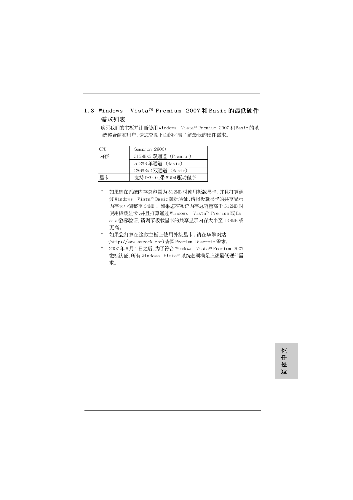
1.31.3
Minimum Hardware RMinimum Hardware R
1.3
Minimum Hardware R
1.31.3
Minimum Hardware RMinimum Hardware R
TMTM
TM
TMTM
VistaVista
Vista
VistaVista
For system integrators and users who purchase this motherboard and
plan to submit Windows® VistaTM Premium 2007 and Basic logo, please f ollow
below table for minimum hardware requirements.
CPU Sempron 2800+
Memory 512MB x 2 Dual Channel (Premium)
VGA DX9.0 with WDDM Driver
* If you use onboard VGA with total system memory size 512MB and plan to
submit Windows® VistaTM Basic logo, please adjust the shared memory size of
onboard VGA to 64MB. If you use onboard VGA with total system memory size above
512MB and plan to submit Windows® VistaTM Premium or Basic logo, please adjust
the shared memory size of onboard VGA to 128MB or above.
* If you plan to use external graphics card on this motherboard, please refer to Premium
Discrete requirement at http://www.asrock.com
* After June 1, 2007, all Windows® VistaTM systems are required to meet above
minimum hardware requirements in order to qualify for Windows® VistaTM Premium
2007 logo.
Premium 2007 and Basic Logo Premium 2007 and Basic Logo
Premium 2007 and Basic Logo
Premium 2007 and Basic Logo Premium 2007 and Basic Logo
512MB Single Channel (Basic)
256MB x 2 Dual Channel (Basic)
equirement Tequirement T
equirement T
equirement Tequirement T
able for Wable for W
able for W
able for Wable for W
indowsindows
indows
indowsindows
®®
®
®®
English
EnglishEnglish
EnglishEnglish
88
8
88
ASRock ALiveNF6P-VSTA Motherboard
Page 9
2.2.
InstallationInstallation
2.
Installation
2.2.
InstallationInstallation
Pre-installation PrecautionsPre-installation Precautions
Pre-installation Precautions
Pre-installation PrecautionsPre-installation Precautions
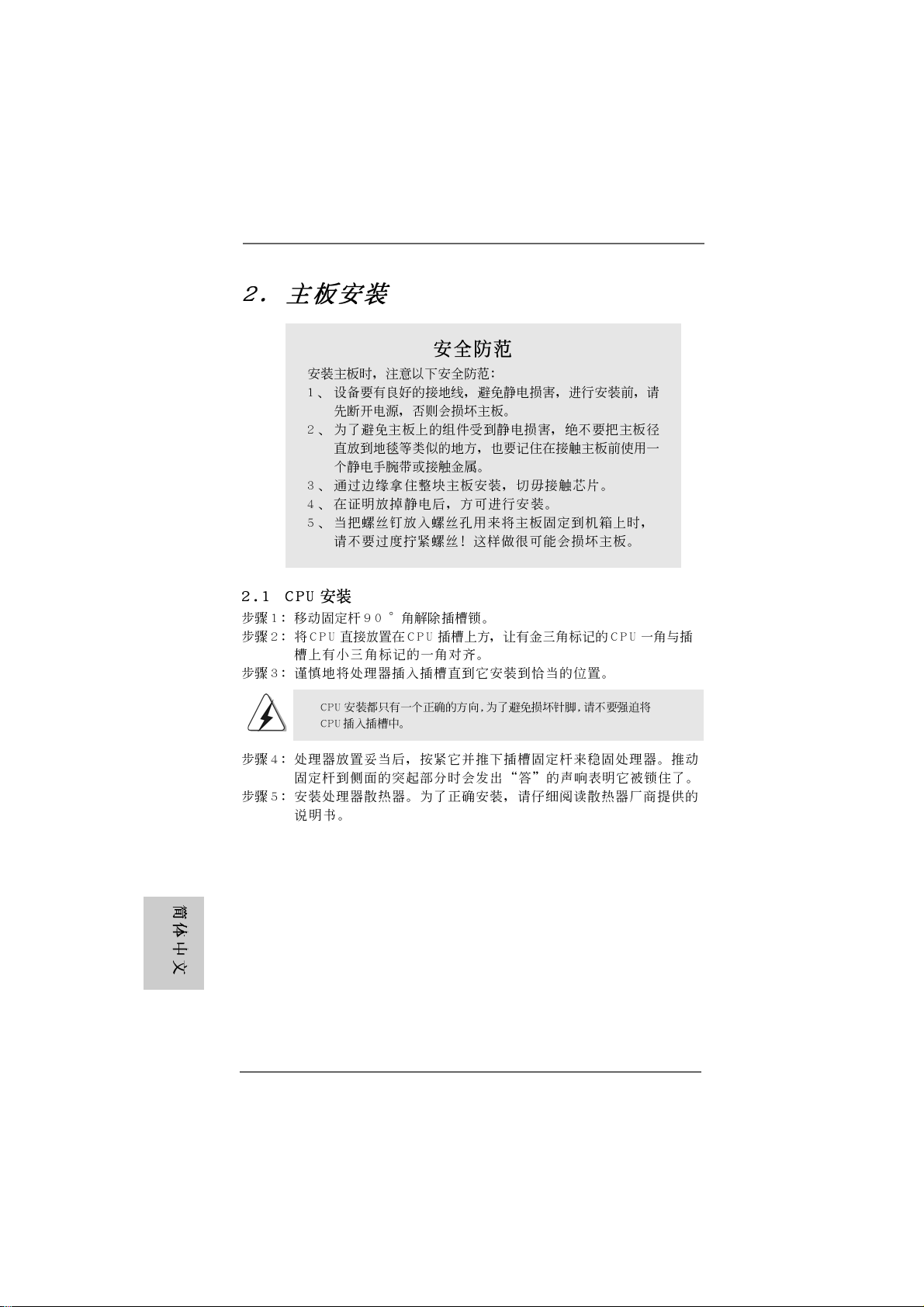
Take note of the following precautions before you install motherboard components or change a ny motherboard settings.
1. Unplug the power cord from the wall socket before touching any
component. Failure to do so may cause severe damage to the
motherboard, peripherals, and/or components.
2. To avoid damaging the motherboard components due to static
electricity, NEVER place your motherboard directly on the carpet or the like. Also remember to use a grounded wrist strap or
touch a safety grounded object before you handle components.
3. Hold components by the edges and do not touch the ICs.
4. Whenever you uninstall any component, place it on a
grounded antstatic pad or in the bag that comes with the
component.
5. When placing screws into the screw holes to secure the
motherboard to the chassis, plea se do not over-tighten the screws!
Doing so may damage the motherboard.
2.12.1
CPU InstallationCPU Installation
2.1
CPU Installation
2.12.1
CPU InstallationCPU Installation
Step 1. Unlock the socket by lifting the lever up to a 90° angle.
Step 2. Position the CPU directly above the socket such that the CPU corner with
the golden triangle matches the socket corner with a small triangle.
Step 3. Carefully insert the CPU into the socket until it fits in place.
The CPU fits only in one correct orientation. DO NOT force the CPU
into the socket to avoid bending of the pins.
Step 4. When the CPU is in place, press it firmly on the socket while you push
down the socket lever to secure the CPU. The lever clicks on the side tab
to indicate that it is locked.
Step 5. Install CPU fan and heatsink. For proper installation, please kindly refer to
the instruction manuals of your CPU fan and heatsink vendors.
ASRock ALiveNF6P-VSTA Motherboard
EnglishEnglish
EnglishEnglish
English
99
9
99
Page 10
2.2 Installation of Memor2.2 Installation of Memor
2.2 Installation of Memor
2.2 Installation of Memor2.2 Installation of Memor
ALiveNF6P-VSTA motherboard provides two 240-pin DDRII (Double Data Rate) DIMM
slots, and supports Dual Channel Memory Technology . For dual cha nnel conf iguration,
you always need to install two identical (the same brand, speed, size and chip-type)
memory modules in the DD RII DIMM slots to activate Dual Cha nnel Memory Technology.
Otherwise, it will operate at single channel mode.
1. It is not allowed to install a DDR memory module into DDRII slot;
otherwise, this motherboard and DIMM may be damaged.
2. If you install only one memory module or two non-identical memory
modules, it is unable to activate the Dual Channel Memory
Technology.
Installing a DIMMInstalling a DIMM
Installing a DIMM
Installing a DIMMInstalling a DIMM
Please make sure to disconnect power supply before adding or
removing DIMMs or the system components.
Step 1. Unlock a DIMM slot by pressing the retaining clips outward.
Step 2. Align a DIMM on the slot such that the notch on the DIMM matches the break
on the slot.
y Modules (DIMM)y Modules (DIMM)
y Modules (DIMM)
y Modules (DIMM)y Modules (DIMM)
English
EnglishEnglish
EnglishEnglish
1010
10
1010
The DIMM only fits in one correct orientation. It will cause permanent
damage to the motherboard and the DIMM if you force the DIMM into the
slot at incorrect orientation.
Step 3. Firmly insert the DIMM into the slot until the retaining clips at both ends fully
sna p back in place a nd the DIMM is properly seated.
ASRock ALiveNF6P-VSTA Motherboard
Page 11

2.3 Expansion Slots (PCI and PCI Express Slots)2.3 Expansion Slots (PCI and PCI Express Slots)
2.3 Expansion Slots (PCI and PCI Express Slots)
2.3 Expansion Slots (PCI and PCI Express Slots)2.3 Expansion Slots (PCI and PCI Express Slots)
There are 2 PCI slots and 2 PCI Express slots on this motherboard.
PCI slots: PCI slots are used to install expansion cards that have the 32-bit PCI
interface.
PCIE slots: PCIE1 (PCIE x1 slot) is used for PCI Express cards with x1 lane width
cards, such as Gigabit LAN card, SATA2 card, etc.
PCIE2 (PCIE x16 slot) is used for PCI Express cards with x16 lane
width graphics cards.
Installing an expansion cardInstalling an expansion card
Installing an expansion card
Installing an expansion cardInstalling an expansion card
Step 1. Before installing the expansion card, please make sure that the power supply
is switched off or the power cord is unplugged. Plea se read the documentation
of the expansion card a nd ma ke necessary hardware
settings for the card before you start the installation.
Step 2. Remove the bracket facing the slot that you intend to use. Keep the screws
for later use.
Step 3. Align the card connector with the slot and press firmly until the card is com-
pletely seated on the slot.
Step 4. Fasten the card to the cha ssis with screws.
ASRock ALiveNF6P-VSTA Motherboard
1111
11
1111
EnglishEnglish
EnglishEnglish
English
Page 12

English
EnglishEnglish
EnglishEnglish
1212
12
1212
2.4 Easy Multi Monitor Feature2.4 Easy Multi Monitor Feature
2.4 Easy Multi Monitor Feature
2.4 Easy Multi Monitor Feature2.4 Easy Multi Monitor Feature
This motherboard supports Multi Monitor upgrade. With the internal onboard VGA and
the external add-on PCI Express VGA card, you can easily enjoy the benefits of Multi
Monitor feature. Plea se refer to the f ollowing ste ps to set up a multi monitor
environment:
1. Install the NVIDIA® PCI Express V GA card to PCIE2 (PCIE x16 slot). Please refer
to page 11 f or proper expansion card installation procedures for details.
2. Connect the D-Sub monitor ca ble to the VGA/D-Sub port on the I/O panel of this
motherboard. Connect another D-Sub monitor ca ble to the VGA/D-Sub connector of
the add-on PCI Express VGA card. Connect the DVI-D monitor ca ble to the
V GA/DVI-D conne ctor of the a dd-on PCI Express VGA card.
3. Boot your system. Press <F2> to enter BIOS setup. Enter “Share Memory”
option to adjust the memory capability to [16MB], [32MB], [64MB], [128MB] or
[256MB] to enable the function of onboard VGA/D-sub. Plea se make sure that
the value you select is less than the total capability of the system memory. If
you do not adjust the BIOS setup, the default value of “Share Memory”, [Auto],
will disable onboard VGA/D-Sub function when the add-on VGA card is inserted
to this motherboard.
4. Install the onboard V GA driver to your system. If you have installed the onboard
V GA driver already, there is no need to install it again.
5. Set up a multi-monitor display.
For Windows® 2000 / XP / XP 64-bit OS:
Right click the desktop, choose “Properties”, and select the “Settings” tab so
that you can adjust the parameters of the multi-monitor according to the steps
below.
A. Click the “Identify” button to display a large number on each monitor.
B. Right-click the display icon in the Display Properties dialog that you wish
to be your primary monitor, and then select “Primary”. When you use
multiple monitors with your card, one monitor will always be Primary, and
all additional monitors will be designated as Secondary.
C. Select the display icon identified by the number 2.
D. Click “Extend my Windows desktop onto this monitor”.
E. Right-click the display icon and select “Attached”, if necessary.
F . Set the “Screen Re solution” a nd “Color Quality” as appropri ate f or the
second monitor. Click “Apply” or “OK” to apply these new values.
G. Repeat steps C through E for the diaplay icon identified by the number
one, two and three.
For Windows® VistaTM / VistaTM 64-bit OS:
Right click the desktop, choose “Personalize”, and sele ct the “Display
Settings” tab so that you can adjust the parameters of the multi-monitor
according to the steps below.
A. Click the number ”2” icon.
ASRock ALiveNF6P-VSTA Motherboard
Page 13
B. Click the items “This is my main monitor” and “Extend the desktop onto
this monitor”.
C. Click “OK” to save your change.
D. Repeat steps A through C for the display icon identified by the number
three.
6. Use Multi Monitor feature. Click and drag the display icons to positions
representing the physical setup of your monitors that you would like to use. The
placement of display icons determines how you move items from one monitor to
another.
2.52.5
Jumpers SetupJumpers Setup
2.5
Jumpers Setup
2.52.5
Jumpers SetupJumpers Setup
The illustration shows how jumpers are
setup. When the jumper cap is placed on
pins, the jumper is “Short”. If no jumper cap
is placed on pins, the jumper is “Open”. The
illustration shows a 3-pin jumper whose pin1
and pin2 are “Short” when jumper cap is
placed on these 2 pins.
Jumper Setting
PS2_USB_PW1 Short pin2, pin3 to enable
(see p.2, No. 1) +5VSB (standby) for PS/2 or
USB wake up events.
Note: To select +5VSB, it requires 2 Amp and higher standby current provided by
power supply.
OpenShort
Clear CMOS Jumper
(CLRCMOS1)
(see p.2, No. 17)
Note: CLRCMOS1 allows you to clear the data in CMOS. The data in CMOS includes
system setup information such as system password, date, time, and system
setup parameters. To clear and reset the system parameters to default setup,
please turn off the computer and unplug the power cord from the power
supply. After waiting for 15 seconds, use a jumper cap to short pin2 and pin3
on CLRCMOS1 for 5 seconds. However, please do not clear the CMOS right
after you update the BIOS. If you need to clear the CMOS when you just finish
updating the BIOS, you must boot up the system first, and then shut it down
before you do the clear-CMOS action.
ASRock ALiveNF6P-VSTA Motherboard
Clear CMOSDefault
1313
13
1313
EnglishEnglish
EnglishEnglish
English
Page 14
2.6 Onboard Headers and Connectors2.6 Onboard Headers and Connectors
2.6 Onboard Headers and Connectors
2.6 Onboard Headers and Connectors2.6 Onboard Headers and Connectors
Onboard headers and connectors are NOT jumpers. Do NOT place
jumper caps over these headers and connectors. Placing jumper
caps over the headers and connectors will cause permanent damage of the motherboard!
•
Floppy Connector
(33-pin FLOPPY1)
(see p.2 No. 18)
the red-striped side to
Pin1
Note: Ma ke sure the red-striped side of the cable is plugged into Pin1 side of the
connector.
Primary IDE connector (Blue)
(39-pin IDE1, see p.2 No. 7)
English
EnglishEnglish
EnglishEnglish
1414
14
1414
connect the blue end
to the motherboard
80-conductor ATA 66/100/133 cable
connect the black end
to the IDE devices
Note: Please refer to the instruction of your IDE device vendor for the details.
Serial A TAII Connectors These four Serial AT AII (SAT AII)
(SATAII_1 (PORT0): see p.2, No. 11) connectors support SAT AII
(SATAII_2 (PORT1): see p.2, No. 12) or SATA hard dis k for intern al
(SATAII_3 (PORT2): see p.2, No. 13) storage devices. The current
(SATAII_4 (PORT3): see p.2, No. 14) SATAII interface allows up to
-
SATAII_1 (PORT0)
SATAII_2 (PORT1)
SATAII_3 (PORT2)
SATAII_4 (PORT3)
3.0 Gb/s data tra n sfer rate.
Serial AT A (SA T A) Either end of the SA T A data cable
Data Cable can be connected to the SATA /
(Optional) SATAII hard disk or the SA TAII
connector on the motherboard.
Serial ATA (SATA) Please conne ct the black end of
Power Cable SAT A power ca ble to the power
(Optional) connector on each drive. Then
connect to the SATA
HDD power connector
connect to
the power
supply
connect the white end of SATA
power cable to the power
connector of the power supply.
ASRock ALiveNF6P-VSTA Motherboard
Page 15
USB 2.0 Header Besides six default USB 2.0
(9-pin USB6_7) ports on the I/O panel, there is
(see p.2 No. 16) one USB 2.0 header on this
motherboard. This USB 2.0
header can support two USB
2.0 ports.
WiFi/E Header This header supports WiFi+AP
(15-pin WIFI/E) function with ASRock
(see p.2 No. 20) WiFi-802.11g or WiFi-802.11n
module, an easy-to-use wireless
local area network (WLAN)
adapter. It allows you to create a
wireless environment and enjoy the
convenience of wireless network
connectivity.
DeskExpress Hot Plug Dete ction This header supports the Hot
Header Plug detection function for
(5-pin IR1) ASRock DeskExpress.
(see p.2 No. 21)
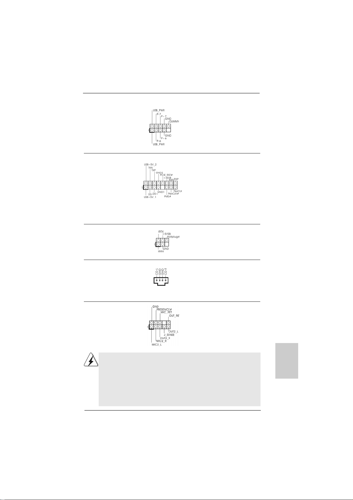
Internal Audio Connectors This connector allows you
(4-pin CD1) to receive stereo audio input
(CD1: see p.2 No. 23) from sound sources such as
CD1
a CD-ROM, D VD-ROM, TV
tuner card, or MPEG card.
Front Panel Audio Header This is an interface for the front
(9-pin HD_AUDIO1) panel audio ca ble that allows
(see p.2, No. 24) convenient connection and
control of audio devices.
1. High Definition Audio supports Jack Sensing, but the panel wire on
the chassis must support HDA to function correctly. Please follow the
instruction in our manual and chassis manual to install your system.
2. If you use AC’97 audio panel, please install it to the front panel audio
header as below:
A. Connect Mic_IN (MIC) to MIC2_L.
B. Connect Audio_R (RIN) to OUT2_R and Audio_L (LIN) to OUT2_L.
C. Connect Ground (GND) to Ground (GND).
ASRock ALiveNF6P-VSTA Motherboard
1515
15
1515
EnglishEnglish
EnglishEnglish
English
Page 16
D. MIC_RET and OUT_RET are for HD audio panel only. You don’t
need to connect them for AC’97 audio panel.
E. Enter BIOS Setup Utility. Enter Advanced Settings, and then select
Chipset Configuration. Set the Front Panel Control option from
[Auto] to [Enabled].
F. Enter Windows system. Click the icon on the lower right hand
taskbar to enter Realtek HD Audio Manager.
For Windows® 2000 / XP / XP 64-bit OS:
Click “Audio I/O”, select “Connector Settings” , choose
“Disable front panel jack detection”, and save the change by
clicking “OK”.
For Windows® VistaTM / VistaTM 64-bit OS:
Click the right-top “Folder” icon , choose “Disable front
panel jack detection”, and save the change by clicking “OK”.
System Panel Hea der This header a ccommodate s
(9-pin PANEL1) several system front panel
(see p.2 No. 15) functions.
Chassis Spe aker He ader Please connect the chassis
(4-pin SPEAKER 1) speaker to this hea der.
(see p.2 No. 10)
English
EnglishEnglish
EnglishEnglish
1616
16
1616
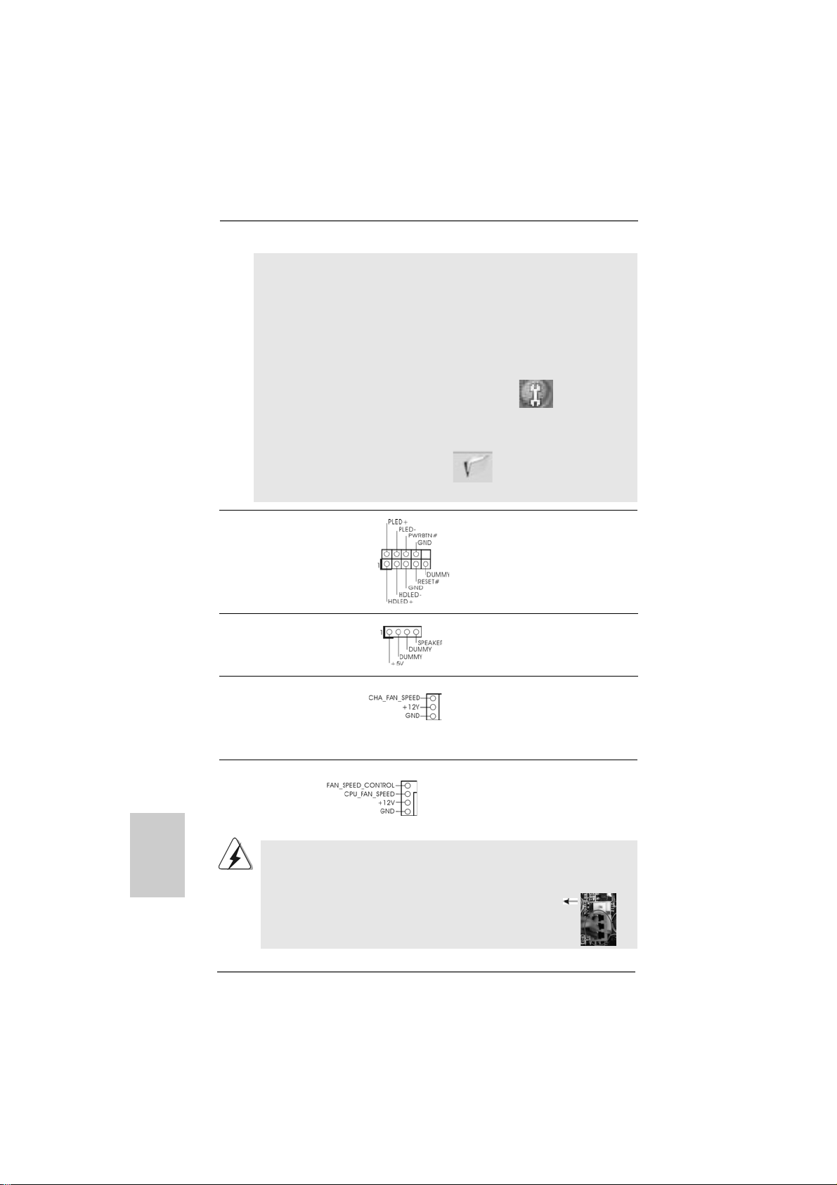
Chassis Fa n Connector Please connect a cha ssis fan
(3-pin CHA_FAN1) cable to this connector and
(see p.2 No. 3) match the bla ck wire to the
ground pin.
CPU Fan Connector Please connect the CPU fa n
(4-pin CPU_FAN1) cable to this connector and
(see p.2 No. 28) match the black wire to the
4
3
2
1
ground pin.
Though this motherboard provides 4-Pin CPU fan (Quiet Fan) support, the 3-Pin
CPU fan still can work successfully even without the fan speed control function.
If you plan to connect the 3-Pin CPU fan to the CPU fan connector on this
motherboard, please connect it to Pin 1-3.
Pin 1-3 Connected
3-Pin Fan Installation
ASRock ALiveNF6P-VSTA Motherboard
Page 17
1
ATX Power Conne ctor Please connect an A TX power
(24-pin ATXPWR1) supply to this connector.
(see p.2, No. 27)
Though this motherboard provides 24-pin ATX power connector,
it can still work if you adopt a traditional 20-pin ATX power supply.
To use the 20-pin ATX power supply, please plug your power
supply along with Pin 1 and Pin 13.
13
12
24
13
1
20-Pin ATX Power Supply Installation
24
ATX 12V Power Connector Please note that it is necessary
(4-pin ATX12V1) to connect a power supply with
(see p.2 No. 2) ATX 12V plug to this connector .
Failing to do so will cause power
up failure.
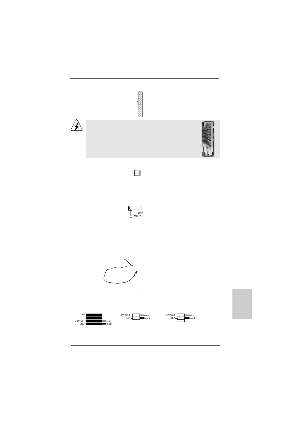
HDMI_SPDIF Header HDMI_SPDIF header, providing
(3-pin HDMI_SPDIF1) SPDIF audio output to HDMI VGA
(see p.2 No. 19) card, allows the system to
connect HDMI Digital TV/
projector/LCD devices. Please
connect the HDMI_SPDIF
connector of HDMI V GA card to
this header.
HDMI_SPDIF Cable Please connect the black end (A)
(Optional) of HDMI_SPDIF cable to the
C
B
A
HDMI_SPDIF header on the
motherboard. Then connect the
white end (B or C) of
HDMI_SPDIF cable to the
HDMI_SPDIF connector of HDMI
VGA card.
12
A. black end B. white end (2-pin) C. white end (3-pin)
ASRock ALiveNF6P-VSTA Motherboard
1717
17
1717
EnglishEnglish
EnglishEnglish
English
Page 18
2.7 HDMI_SPDIF Header Connection Guide2.7 HDMI_SPDIF Header Connection Guide
2.7 HDMI_SPDIF Header Connection Guide
2.7 HDMI_SPDIF Header Connection Guide2.7 HDMI_SPDIF Header Connection Guide
HDMI (High-Definition Multi-media Interfa ce) is an all-digital audio/video specification,
which provides an interface between any compatible digital audio/video source,
such as a set-top box, DVD player, A/V receiver and a compatible digital audio or
video monitor, such as a digital television (DTV). A complete HDMI system requires a
HDMI VGA card and a HDMI ready motherboard with a HDMI_SPDIF header. This
motherboard is equipped with a HDMI_SPDIF header, which provides SPDIF audio
output to HDMI VGA card, allows the system to connect HDMI Digital TV/projector/
LCD devices. To use HDMI function on this motherboard, please carefully follow the
below steps.
•
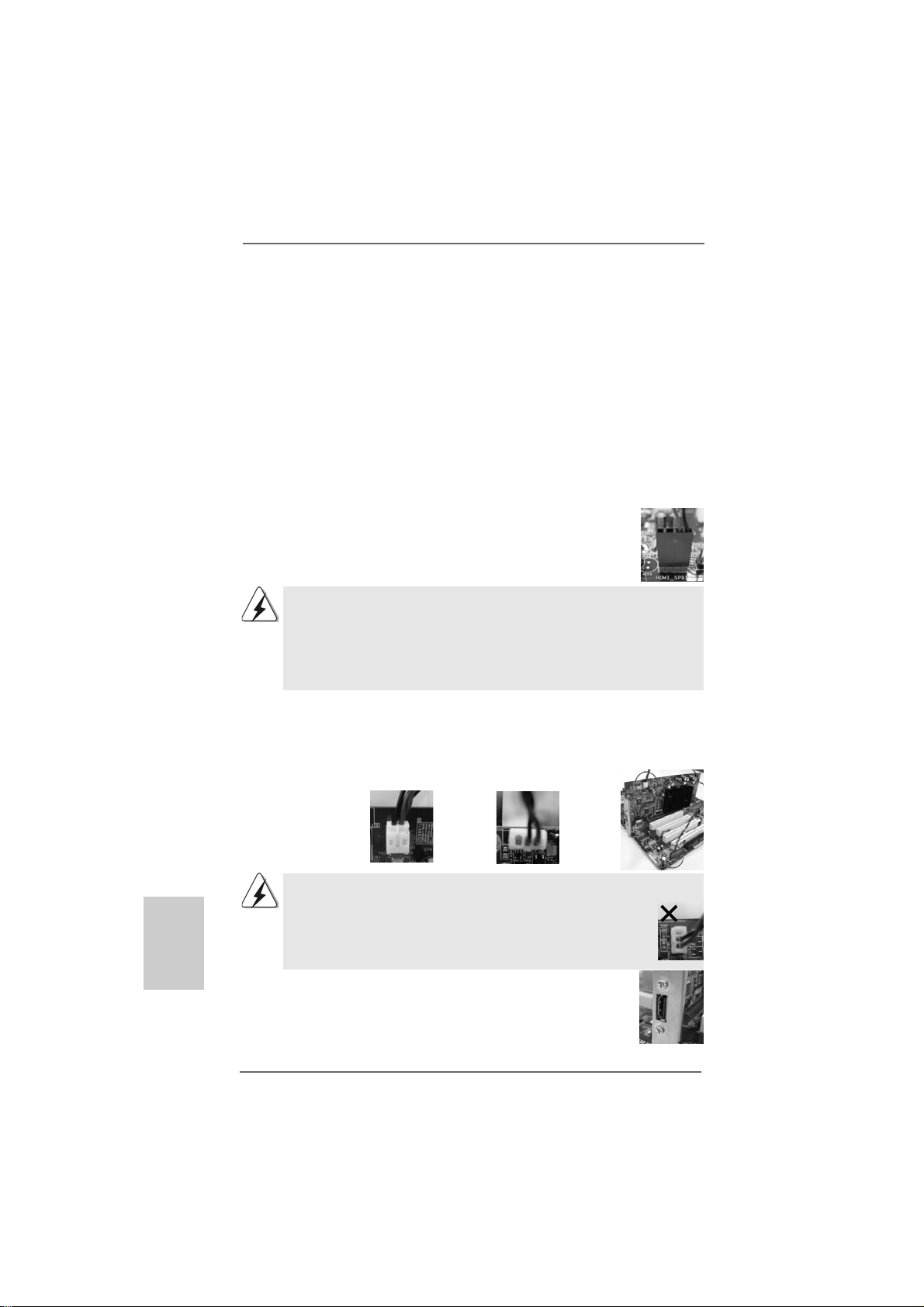
Step 1. Install the HDMI VGA card to the PCI Express Graphics slot on this
motherboard. For the proper installation of HDMI VGA card, please refer
to the installation guide on page 1 1.
Step 2. Connect the black end (A) of HDMI_SPDIF cable to the
HDMI_SPDIF header (HDMI_SPDIF1, yellow, see page 2,
No. 19) on the motherboard.
Make sure to correctly connect the HDMI_SPDIF cable to the motherboard and the
HDMI VGA card according to the same pin definition. For the pin definition of
HDMI_SPDIF header and HDMI_SPDIF cable connectors, please refer to page 17.
For the pin definition of HDMI_SPDIF connectors on HDMI VGA card, please refer to
the user manual of HDMI VGA card vendor. Incorrect connection may cause
permanent damage to this motherboard and the HDMI VGA card.
Step 3. Connect the white end (B or C) of HDMI_SPDIF cable to the HDMI_SPDIF
connector of HDMI VGA card. (There are two white ends (2-pin and 3-pin)
on HDMI_SPDIF cable. Please choose the appropriate white end according
to the HDMI_SPDIF connector of the HDMI VGA card you install.
English
EnglishEnglish
EnglishEnglish
1818
18
1818
white end
(2-pin) (B)
Please do not connect the white end of HDMI_SPDIF cable to the wrong connector
of HDMI VGA card or other VGA card. Otherwise, the motherboard and the
VGA card may be damaged. For example, this picture shows the wrong
example of connecting HDMI_SPDIF cable to the fan connector of PCI
Express VGA card. Please refer to the VGA card user manual for
connector usage in advance.
white end
(3-pin) (C)
Step 4. Connect the HDMI output connector on HDMI VGA card to
HDMI device, such as HDTV. Please refer to the user manual
of HDTV and HDMI VGA card vendor for detailed connection
procedures.
Step 5. Install HDMI VGA card driver to your system.
ASRock ALiveNF6P-VSTA Motherboard
Page 19
2.82.8
SASA
TT
2.8
2.82.8
Before installing SATAII hard disk to your computer, please carefully read below
SATAII hard disk setup guide. Some default setting of SATAII hard disks may not be
at SATAII mode, which operate with the best performance. In order to enable SATAII
function, please follow the below instruction with different vendors to correctly
adjust your SA TAII hard disk to SATAII mode in advance; otherwise, your SATAII hard
disk may fail to run at SATAII mode.
Western Digital
If pin 5 and pin 6 are shorted, SATA 1.5Gb/s will be enabled.
On the other hand, if you want to enable SATAII 3.0Gb/s, please remove the jumpers
from pin 5 and pin 6.
SAMSUNG
If pin 3 and pin 4 are shorted, SATA 1.5Gb/s will be enabled.
On the other hand, if you want to enable SATAII 3.0Gb/s, please remove the jumpers
from pin 3 and pin 4.
AII Hard Disk Setup GuideAII Hard Disk Setup Guide
SA
T
AII Hard Disk Setup Guide
SASA
TT
AII Hard Disk Setup GuideAII Hard Disk Setup Guide
HITACHI
Please use the Feature Tool, a DOS-bootable tool, for changing various A TA feature s.
Please visit HITACHI’s website for details:
http://www.hitachigst.com/hdd/support/download.htm
The above examples are just for your reference. For different SATAII hard
disk products of different vendors, the jumper pin setting methods may not
be the same. Please visit the vendors’ website for the updates.
ASRock ALiveNF6P-VSTA Motherboard
1919
19
1919
EnglishEnglish
EnglishEnglish
English
Page 20
2.92.9
2.9
2.92.9
This motherboard adopts NVIDIA® GeForce 6150SE / nForce 430 chipset that
supports Serial AT A (SATA) / Serial AT AII (SATAII) hard dis ks a nd RAID functions. You
may install SA TA / SAT AII hard disk s on this motherboard f or internal storage device s.
This section will guide you to install the SA TA / SATAII hard disks.
STEP 1: Install the SATA / SAT AII hard disk s into the drive bays of your chassis.
STEP 2: Connect the SATA power ca ble to the SAT A / SATAII hard disk.
STEP 3: Connect one end of the SATA data cable to the motherboard’s SAT AII
STEP 4: Connect the other end of the SATA data cable to the SAT A / SA TAII hard
2.102.10
2.10
2.102.10
This motherboard supports Hot Plug and Hot Swap functions for SA TA / SATAII
Devices.
Serial ASerial A
Serial A
Serial ASerial A
InstallationInstallation
Installation
InstallationInstallation
connector.
disk.
Hot Plug and Hot Swap FHot Plug and Hot Swap F
Hot Plug and Hot Swap F
Hot Plug and Hot Swap FHot Plug and Hot Swap F
HDDsHDDs
HDDs
HDDsHDDs
TT
A (SAA (SA
TT
A (SA
A (SAA (SA
A) / Serial AA) / Serial A
T
A) / Serial A
TT
A) / Serial AA) / Serial A
T
TT
NOTE
What is Hot Plug Function?
If the SATA / SATAII HDDs are NOT set for RAID configuration, it is
called “Hot Plug” for the action to insert and remove the SATA / SATAII
HDDs while the system is still power-on and in working condition.
However, please note that it cannot perform Hot Plug if the OS has
been installed into the SATA / SATAII HDD.
TT
AII (SAAII (SA
T
AII (SA
TT
AII (SAAII (SA
unctions for SAunctions for SA
unctions for SA
unctions for SAunctions for SA
TT
AII) Hard DisksAII) Hard Disks
T
AII) Hard Disks
TT
AII) Hard DisksAII) Hard Disks
TT
A / SAA / SA
T
A / SA
TT
A / SAA / SA
TT
T
TT
AIIAII
AII
AIIAII
English
EnglishEnglish
EnglishEnglish
2020
20
2020
What is Hot Swap Function?
If SATA / SATAII HDDs are built as RAID1 or RAID 5 then it is called
“Hot Swap” for the action to insert and remove the SATA / SATAII
HDDs while the system is still power-on and in working condition.
ASRock ALiveNF6P-VSTA Motherboard
Page 21
2.112.11
Driver Installation GuideDriver Installation Guide
2.11
Driver Installation Guide
2.112.11
Driver Installation GuideDriver Installation Guide
To install the drivers to your system, plea se insert the support CD to your optical drive
first. Then, the drivers compatible to your system ca n be auto-detected and listed on
the support CD driver page. Please follow the order from up to bottom side to install
those required drivers. Therefore, the drivers you install ca n work properly .
2.122.12
Installing WindowsInstalling Windows
2.12
Installing Windows
2.122.12
Installing WindowsInstalling Windows
TMTM
TM
/ Vista/ Vista
/ Vista
/ Vista/ Vista
If you just want to install Windows® 2000, Windows® XP , Windows® XP 64-bit, Windows
VistaTM or Windows® VistaTM 64-bit on your SATA / SAT AII HDDs without RAID functions,
you don’t have to make a SA T A / SAT AII driver diskette. Besides, there is no need f or you
to change the BIOS setting. You can start to install Windows® 2000, Windows® XP,
Windows® XP 64-bit, Windows® VistaTM or Windows® VistaTM 64-bit on your system
directly.
2.132.13
Installing WindowsInstalling Windows
2.13
Installing Windows
2.132.13
Installing WindowsInstalling Windows
/ Vista/ Vista
/ Vista
/ Vista/ Vista
If you want to install Windows® 2000, Windows® XP, Windows® XP 64-bit, Windows
VistaTM or Windows® VistaTM 64-bit OS on your SATA / SAT AII HDDs with RAID
functions, plea se f ollow below procedures according to the OS you install.
2.13.1 Installing Windows2.13.1 Installing Windows
2.13.1 Installing Windows
2.13.1 Installing Windows2.13.1 Installing Windows
F F
F
F F
If you want to install Windows® 2000, Windows® XP or Windows® XP 64-bit on your
SATA / SATAII HDDs with RAID functions, plea se f ollow below steps.
TMTM
64-bit W 64-bit W
64-bit W
64-bit W 64-bit W
TMTM
TM
TMTM
64-bit W 64-bit W
64-bit W
64-bit W 64-bit W
Before installing Windows® 2000 to your system, your Windows® 2000 optical
disk is supposed to include SP4. If there is no SP4 included in your disk, please
visit the below website for proper procedures of making a SP4 disk:
http://www.microsoft.com/Windows2000/downloads/servicepacks/sp4/spdeploy.
htm#the_integrated_installation_fmay
unctionsunctions
unctions
unctionsunctions
®
2000 / XP / XP 64-bit / Vista 2000 / XP / XP 64-bit / Vista
2000 / XP / XP 64-bit / Vista
2000 / XP / XP 64-bit / Vista 2000 / XP / XP 64-bit / Vista
ithout RAID Fithout RAID F
ithout RAID F
ithout RAID Fithout RAID F
®
2000 / XP / XP 64-bit / Vista 2000 / XP / XP 64-bit / Vista
2000 / XP / XP 64-bit / Vista
2000 / XP / XP 64-bit / Vista 2000 / XP / XP 64-bit / Vista
ith RAID Fith RAID F
ith RAID F
ith RAID Fith RAID F
®
2000 / XP / XP 64-bit With RAID 2000 / XP / XP 64-bit With RAID
2000 / XP / XP 64-bit With RAID
2000 / XP / XP 64-bit With RAID 2000 / XP / XP 64-bit With RAID
unctionsunctions
unctions
unctionsunctions
unctionsunctions
unctions
unctionsunctions
TMTM
TM
TMTM
TMTM
TM
TMTM
®
®
STEP 1: Make a SATA / SATAII Driver Diskette.
A. Insert the ASRock Support CD into your optical drive to boot your system.
B. During POST at the beginning of system boot-up, press <F11> key, and
then a window for boot devices selection appears. Please sele ct CD-ROM
as the boot device.
C. When you see the message on the screen, “Generate Serial ATA driver
diskette [YN]?”, press <Y>.
ASRock ALiveNF6P-VSTA Motherboard
2121
21
2121
EnglishEnglish
EnglishEnglish
English
Page 22

D. Then you will see these messages,
Please insert a blank
formatted diskette into floppy
drive A:
press any key to start
Please in sert a floppy dis kette into the floppy drive, and press any key.
E. The system will start to format the floppy diskette and copy SATA / SATAII
drivers into the floppy diskette.
STEP 2: Set Up BIOS.
A. Enter BIOS SETUP UTILITY Advanced screen IDE Configuration.
B. Set the “SAT A Operation Mode” option to [RAID].
STEP 3: Use “RAID Installation Guide” to set RAID configuration.
Before you start to configure RAID function, you need to check the RAID installation
guide in the Support CD f or proper configuration. Please refer to the BIOS RAID
installation guide in the following path in the Support CD:
.. \ RAID Installation Guide
STEP 4: Install Windows® 2000 / Windows® XP / Windows® XP 64-bit OS on
your system.
After step1, 2, 3, you can start to install Windows® 2000 / Windows® XP / Windows® XP
64-bit OS on your system. At the beginning of Windows® setup, press F6 to install a
third-party RAID driver . When prompted, in sert the SA T A / SA T AII driver diskette containing the NVIDIA® RAID driver. After reading the floppy dis k, the driver will be presented.
Select the driver to install according to the mode you choose and the OS you install.
NOTE. If you install Windows® 2000 / Windows® XP / Windows® XP 64-bit on IDE
HDDs and want to manage (create, convert, delete, or rebuild) RAID functions
on SATA / SATAII HDDs, you still need to set up “SATA Operation Mode” to [RAID] in
BIOS first. Then, please set the RAID configuration by using the Windows RAID
installation guide in the following path in the Support CD:
.. \ RAID Installation Guide
English
EnglishEnglish
EnglishEnglish
2222
22
2222
Vista Vista
Vista
Vista Vista
TM TM
TM
TM TM
/ Vista/ Vista
/ Vista
/ Vista/ Vista
2.13.2 Installing Windows2.13.2 Installing Windows
2.13.2 Installing Windows
2.13.2 Installing Windows2.13.2 Installing Windows
RAID F RAID F
RAID F
RAID F RAID F
If you want to install Windows® VistaTM or Windows® VistaTM 64-bit on your SATA /
SATAII HDDs with RAID function s, please follow below steps.
STEP 1: Set Up BIOS.
A. Enter BIOS SETUP UTILITY Advanced screen IDE Configuration.
B. Set the “SAT A Operation Mode” option to [RAID].
unctionsunctions
unctions
unctionsunctions
ASRock ALiveNF6P-VSTA Motherboard
®
TMTM
TM
TMTM
64-bit With 64-bit With
64-bit With
64-bit With 64-bit With
Page 23
STEP 2: Use “RAID Installation Guide” to set RAID configuration.
Before you start to configure RAID function, you need to check the RAID installation
guide in the Support CD f or proper configuration. Please refer to the BIOS RAID
installation guide part of the document in the following path in the Support CD:
.. \ RAID Installation Guide
STEP 3: Install Windows® VistaTM / Windows® VistaTM 64-bit OS on your
system.
Insert the Windows® VistaTM / Windows® VistaTM 64-bit optical disk into the optical drive
to boot your system, and follow the instruction to install Windows® VistaTM / Windows
VistaTM 64-bit OS on your system. When you see “Where do you want to install Windows?
” page, please insert the ASRock Support CD into your optical drive, a nd click the “Load
Driver” button on the left on the bottom to load the NVIDIA® RAID drivers. NVIDIA® RAID
drivers are in the following path in our Support CD:
.. \ I386 \ Vista (For Windows® Vista
.. \ AMD64 \ Vista64 (For Windows® Vista
After that, please insert Windows® VistaTM / Windows® VistaTM 64-bit optical disk into
the optical drive again to continue the installation.
NOTE. If you install Windows® VistaTM / Windows® VistaTM 64-bit on IDE HDDs and want to
manage (create, convert, delete, or rebuild) RAID functions on SATA / SATAII HDDs,
you still need to set up “SATA Operation Mode” to [RAID] in BIOS first. Then, please
set the RAID configuration by using the Windows RAID installation guide in the
following path in the Support CD:
.. \ RAID Installation Guide
TM
OS)
TM
64-bit OS)
®
2.142.14
Untied Overclocking TUntied Overclocking T
2.14
Untied Overclocking T
2.142.14
Untied Overclocking TUntied Overclocking T
This motherboard supports Untied Overclocking Technology, which means during
overclocking, FSB enjoys better margin due to fixed PCI / PCIE buses. Before you
enable Untied Overclocking function, plea se enter “Overclock Mode” option of BIOS setup
to set the selection from [Auto] to [CPU, PCIE, Async.]. Therefore, CPU FSB is untied
during overclocking, but PCI / PCIE buses are in the fixed mode so that FSB can operate
under a more stable overclocking environment.
Please refer to the warning on page 6 for the possible overclocking risk
before you apply Untied Overclocking Technology.
ASRock ALiveNF6P-VSTA Motherboard
echnologyechnology
echnology
echnologyechnology
2323
23
2323
EnglishEnglish
EnglishEnglish
English
Page 24

3. BIOS Information3. BIOS Information
3. BIOS Information
3. BIOS Information3. BIOS Information
The Flash Memory on the motherboard stores BIOS Setup Utility. When you start up
the computer, please press <F2> during the Power-On-Self-Test (POST) to enter
BIOS Setup utility; otherwise, POST continues with its test routines. If you wish to
enter BIOS Setup after POST, please restart the system by pressing <Ctl> + <Alt> +
<Delete>, or pressing the reset button on the system chassis. The BIOS Setup progra m
is designed to be user-friendly . It is a menu-driven program, which allows you to scroll
through its various sub-menus and to select a mong the predetermined choice s. For the
detailed information about BIOS Setup, plea se refer to the User M a nual (PDF f ile) contained in the Support CD.
English
EnglishEnglish
EnglishEnglish
4. Software Suppor4. Software Suppor
4. Software Suppor
4. Software Suppor4. Software Suppor
This motherboard supports various Microsoft® Windows® operating systems: 2000 /
XP / XP Media Center / XP 64-bit / VistaTM / VistaTM 64-bit. The Support CD that came
with the motherboard contains necessary drivers and useful utilities that will enhance motherboard features. To begin using the Support CD, insert the CD into your CDROM drive. It will display the Main Menu automatically if “AUTORUN” is enabled in your
computer. If the Main Menu does not appear automatically, locate and double-click on
the file “ASSETUP.EXE” from the “BIN” folder in the Support CD to display the menus.
t CD informationt CD information
t CD information
t CD informationt CD information
2424
24
2424
ASRock ALiveNF6P-VSTA Motherboard
Page 25
ASRock ALiveNF6P-VSTA Motherboard
2525
25
2525
Page 26
™
‘ ’ ™
®
®
®
2626
26
2626
ASRock ALiveNF6P-VSTA Motherboard
Page 27
®
®
ASRock ALiveNF6P-VSTA Motherboard
2727
27
2727
Page 28
® ®
®
® ®
2828
28
2828
ASRock ALiveNF6P-VSTA Motherboard
Page 29
®
®
®
®
®
®
ASRock ALiveNF6P-VSTA Motherboard
2929
29
2929
Page 30
3030
30
3030
ASRock ALiveNF6P-VSTA Motherboard
Page 31

ASRock ALiveNF6P-VSTA Motherboard
3131
31
3131
Page 32

3232
32
3232
ASRock ALiveNF6P-VSTA Motherboard
Page 33

®
®
®
ASRock ALiveNF6P-VSTA Motherboard
3333
33
3333
Page 34

3434
34
3434
ASRock ALiveNF6P-VSTA Motherboard
Page 35

SATAII_1 (PORT0)
SATAII_2 (PORT1)
SATAII_3 (PORT2)
SATAII_4 (PORT3)
ASRock ALiveNF6P-VSTA Motherboard
3535
35
3535
Page 36

CD1
®
3636
36
3636
®
ASRock ALiveNF6P-VSTA Motherboard
Page 37

4
3
2
1
1
13
12
24
13
1
ASRock ALiveNF6P-VSTA Motherboard
24
12
3737
37
3737
Page 38

C
B
A
3838
38
3838
ASRock ALiveNF6P-VSTA Motherboard
Page 39

ASRock ALiveNF6P-VSTA Motherboard
3939
39
3939
Page 40

4040
40
4040
ASRock ALiveNF6P-VSTA Motherboard
Page 41

®
ASRock ALiveNF6P-VSTA Motherboard
4141
41
4141
Page 42

®
®
®
®
®
®
®
®
®
®
®
®
®
®
®
®
®
®
®
®
®
®
4242
42
4242
ASRock ALiveNF6P-VSTA Motherboard
Page 43

®
® ®
® ® ®
®
®
® ®
®
®
®
®
ASRock ALiveNF6P-VSTA Motherboard
4343
43
4343
Page 44

®
®
® ®
®
®
®
®
®
®
®
®
4444
44
4444
ASRock ALiveNF6P-VSTA Motherboard
Page 45

® ®
ASRock ALiveNF6P-VSTA Motherboard
4545
45
4545
Page 46

4646
46
4646
X O O O O O
X O O O O O
O:
X:
ASRock ALiveNF6P-VSTA Motherboard
Page 47
O
O
1. Einführung1. Einführung
1. Einführung
1. Einführung1. Einführung
Wir danken Ihnen für den Kauf des ASRock ALiveNF6P-VSTA Motherboard, ein
zuverlässiges Produkt, welches unter den ständigen, strengen Qualitätskontrollen von
ASRock gefertigt wurde. Es bietet Ihnen exzellente Leistung und robustes Design, ge mäß
der Verpflichtung von ASRock zu Qualität und Halbarkeit.
Diese Schnellinstallationsanleitung führt in das Motherboard und die schrittweise
Installation ein. Details über das Motherboard finden Sie in der Bedienungsanleitung
auf der Support-CD.
Da sich Motherboard-Spezifikationen und BIOS-Software verändern
können, kann der Inhalt dieses Handbuches ebenfalls jederzeit geändert
werden. Für den Fall, dass sich Änderungen an diesem Handbuch
ergeben, wird eine neue Version auf der ASRock-Website, ohne weitere
Ankündigung, verfügbar sein. Die neuesten Grafikkarten und unterstützten
CPUs sind auch auf der ASRock-Website aufgelistet.
ASRock-Website: http://www.asrock.com
Wenn Sie technische Unterstützung zu Ihrem Motherboard oder spezifische
Informationen zu Ihrem Modell benötigen, besuchen Sie bitte unsere
Webseite:
www.asrock.com/support/index.asp
1.1 Kartoninhalt
ASRock ALiveNF6P-VSTA Motherboard
(Micro ATX-Formfaktor: 24.4 cm x 19.6 cm; 9.6 Zoll x 7.7 Zoll)
ASRock ALiveNF6P-VSTA Schnellinstallationsanleitung
ASRock ALiveNF6P-VSTA Support-CD
Ein 80-adriges Ultra-ATA 66/100/133 IDE-Flachbandkabel
Ein Flachbandkabel für ein 3,5-Zoll-Diskettenlaufwerk
Ein Seriell-ATA- (SATA) Datenkabel (Option)
Ein Seriell-ATA (SATA) Festplattennetzkabel (Option)
Ein HDMI_SPDIF-Kabel (Option)
Ein “ASRock 6CH I/O Plus” I/O Shield
ASRock ALiveNF6P-VSTA Motherboard
4747
47
4747
DeutschDeutsch
DeutschDeutsch
Deutsch
Page 48

Deutsch
DeutschDeutsch
DeutschDeutsch
4848
48
4848
1.21.2
SpezifikationenSpezifikationen
1.2
Spezifikationen
1.21.2
SpezifikationenSpezifikationen
Plattform - Micro ATX-Formfaktor: 24.4 cm x 19.6 cm; 9.6 Zoll x 7.7 Zoll
CPU - AM2 Sockel, unterstützt AMD PhenomTM X4 / X2, Athlon 64FX
/ 64X2 / X2 / 64 und Sempron Prozessoren
- AMD LIVE!TM-bereit
- Unterstützt Cool ‘n’ Quiet™-T echnologie von AMD
- FSB 1000 MHz (2.0 GT/s)
- Unterstützt U ntied-Übertaktungstechnologie
(siehe VORSICHT 1)
- Unterstützt Hyper-T ransport-Technologie
Chipsatz - NVIDIA® GeForce 6150SE / nForce 430
Speicher - Unterstützung von Dual-Kan al-Speichertechnologie
(siehe VORSICHT 2)
- 2 x Steckplätze für DD RII
- Unterstützt DDRII1066/800/667/533 (siehe VORSICHT 3)
- Max. 4GB (siehe VORSICHT 4)
Hybrid Booster - Schrittloser CPU-Frequenz-Kontrolle (siehe VORSICHT 5)
- ASRock U-COP (siehe VORSICHT 6)
- Boot Failure Guard (B.F.G. – Systemstartfehlerschutz)
- ASRock AM2 Boost: ASRocks patentgeschützte T echnologie
zur Erhöhung der Arbeitsspeicherleistung um bis zu 12,5%
(siehe VORSICHT 7)
Erweiterungs- - 1 x PCI Express x16-Steckplätze
steckplätze - 1 x PCI Express x1-Steckplätze
- 2 x PCI-Steckplätze
Onboard-VGA - Integrierter N VIDIA® GeForce6 Grafikchip
- DX9.0 VGA, Pixel Shader 3.0
- Maximal gemeinsam genutzter Speicher 256 MB
Audio - 5.1 CH Windows® VistaTM Premium Level HD Audio
(ALC662 Audio Codec)
LAN - Realtek PHY RTL8201CL
- Speed: 10/100 Ethernet
- Unterstützt W a ke-On-LAN
E/A-Anschlüsse ASRock 6CH I/O Plus
an der - 1 x PS/2 Mouse Port
Rückseite - 1 x PS/2 Keyboard Port
- 1 x Serieller port: COM 1
- 1 x VGA Port
- 1 x Parallel Port (ECP/EPP Support)
- 6 x Ready-to-Use USB 2.0 Ports
- 1 x RJ-45 Port
ASRock ALiveNF6P-VSTA Motherboard
Page 49

- Audioa n schlüsse: Line In / Line Out / Mikrofon
Anschlüsse - 4 x SATAII-Anschlüsse, unterstützt bis 3.0 Gb/s
Datenübertragungsrate, unterstützt RAID (RAID 0, RAID 1,
RAID 0+1, RAID 5 und JBOD), NCQ und “Hot Plug” Funktionen
(siehe VORSICHT 8)
- 1 x ATA133 IDE-An schlüsse (U nterstützt bis 2 IDE-Geräte)
- 1 x FDD-Anschlüsse
- 1 x DeskExpress heißer Stecker Detektionskopf
- 1 x HDMI_SPDIF-Anschluss
- CPU/Gehäuse-Lüfteranschluss
- 24-pin A TX-Netz-Header
- 4-pin anschluss für 12V-ATX-Netzteil
- Interne Audio-Anschlüsse
- Anschluss für Audio auf der Gehäusevorderseite
- 1 x USB 2.0-Anschlüsse (Unterstützung 2
zusätzlicher USB 2.0-Anschlüsse) (siehe VORSICHT 9)
- 1 x WiFi/E-Anschlüsse (siehe VORSICHT 10)
BIOS - 4Mb AMI BIOS
- AMI legal BIOS mit Unterstützung für “Plug and Play”
- ACPI 1.1-Weckfunktionen
- JumperFree-Modus
- SMBIOS 2.3.1
Support-CD - Treiber, Dienstprogramme, Antivirussoftware
(Probeversion)
Hardware Monitor - CPU-T emperatursensor
- Motherboardtemperaturerkennung
- Drehza hlmessung für CPU-Lüfter
- Drehzahlmessung für Gehäuselüfter
- CPU-Lüftergeräuschdämpfung
- Spannungsüberwachung: +12V, +5V, +3.3V, Vcore
Betriebssysteme - Unterstützt Microsoft® Windows® 2000 / XP / XP Media
Center / XP 64-Bit / VistaTM / VistaTM 64-Bit
Zertifizierungen - FCC, CE, WHQL
WARNUNG
Beachten Sie bitte, dass Overclocking, einschließlich der Einstellung im BIOS, Anwenden
der Untied Overclocking-Technologie oder Verwenden von Overclocking-Werkzeugen von
Dritten, mit einem gewissen Risiko behaftet ist. Overclocking kann sich nachteilig auf die
Stabilität Ihres Systems auswirken oder sogar Komponenten und Geräte Ihres Systems
beschädigen. Es geschieht dann auf eigene Gefahr und auf Ihre Kosten. Wir übernehmen
keine Verantwortung für mögliche Schäden, die aufgrund von Overclocking verursacht
wurden.
ASRock ALiveNF6P-VSTA Motherboard
4949
49
4949
DeutschDeutsch
DeutschDeutsch
Deutsch
Page 50

Deutsch
DeutschDeutsch
DeutschDeutsch
VORSICHT!
1. Dieses Motherboard unterstützt die Untied-Übertaktungstechnologie.
Unter “Entkoppelte Übertaktungstechnologie” auf Seite 69 finden Sie
detaillierte Informationen.
2. Dieses Motherboard unterstützt Dual-Kanal-Speichertechnologie. Vor
Implementierung der Dual-Kanal-Speichertechnologie müssen Sie die
Installationsanleitung für die Speichermodule auf Seite 53 zwecks
richtigerInstallation gelesen haben.
3. Ob die Speichergeschwindigkeit 1066 MHz unterstützt wird, hängt von
der von Ihnen eingesetzten AM2+-CPU ab. Da sich die DDRII1066Spezifikation außerhalb des JEDEC-Speicherstandards befindet,
schauen Sie bitte auf unseren Internetseiten in der Liste mit unterstützten
Speichermodulen nach, wenn Sie DDRII1066-Speichermodule einsetzen
möchten.
ASRock-Internetseite: http://www.asrock.com
4. Durch Betriebssystem-Einschränkungen kann die tatsächliche
Speichergröße weniger als 4 GB betragen, da unter Windows® XP und
Windows® Vista™ etwas Speicher zur Nutzung durch das System
reserviert wird. Unter Windows® XP 64-bit und Windows® Vista™ 64-bit
mit 64-Bit-CPU besteht diese Einschränkung nicht.
5. Obwohl dieses Motherboard stufenlose Steuerung bietet, wird
Overclocking nicht empfohlen. Frequenzen, die von den empfohlenen
CPU-Busfrequenzen abweichen, können Instabilität des Systems
verursachen oder die CPU beschädigen.
6. Wird eine Überhitzung der CPU registriert, führt das System einen
automatischen Shutdown durch. Bevor Sie das System neu starten,
prüfen Sie bitte, ob der CPU-Lüfter am Motherboard richtig funktioniert,
und stecken Sie bitte den Stromkabelstecker aus und dann wieder ein.
Um die Wärmeableitung zu verbessern, bitte nicht vergessen, etwas
Wärmeleitpaste zwischen CPU und Kühlkörper zu sprühen.
7. Dieses Motherboard unterstützt die ASRock AM2 Boost
Übertaktungstechnologie. Wenn Sie diese Funktion im BIOS-Setup
aktivieren, wird die Arbeitsspeicherleistung um bis zu 12,5% gesteigert.
Die Wirkung hängt aber von der verwendeten AM2 CPU ab. Diese
Funktion übertaktet die Standardfrequenz des Chipsatz und der CPU.
Dennoch gewähren wir die Systemstabilität nicht bei allen CPU/DRAMKonfigurationen. Wird Ihr System nach dem Aktivieren der AM2 BoostFunktion unstabil, dann ist diese Funktion wahrscheinlich nicht für Ihr
System geeignet. Sie können diese Funktion deaktivieren, um die
Stabilität Ihres System zu bewahren.
8. Bevor Sie eine SATA II Festplatte mit dem SATA II Anschluss verbinden,
lesen Sie bitte die “Anleitung zur SATA II Festplatteneinrichtung“ auf
Seite 64, um Ihre SATA II Festplatte in den SATA II Modus umzuschalten.
SATA-Festplatten können Sie auch direkt mit dem SATA II-Anschluss
verbinden.
5050
50
5050
ASRock ALiveNF6P-VSTA Motherboard
Page 51

9. Das Power Management für USB 2.0 arbeitet unter Microsoft
Windows® VistaTM 64-Bit / VistaTM / XP 64-Bit / XP SP1 oder SP2/2000
SP4 einwandfrei.
10. WiFi/E Sockel unterstützt WiFi+AP Funktion mit ASRock WiFi-802.11g
oder WiFi-802.11n Modul, einem einfach zu bedienenden Wireless
Local Area Network (WLAN) Adapter. Damit sind Sie in der Lage, ein
drahtloses Netzwerk aufzubauen und die Vorzüge drahtloser
Anschlussmöglichkeiten zu genießen. Für Verfügbarkeit des ASRock
WiFi-802.11g oder WiFi-802.11n Moduls, siehe bitte unsere
Webseite.
ASRock Webseite http://www.asrock.com
®
1.31.3
Minimale Hardwarevorausetzungen für WindowsMinimale Hardwarevorausetzungen für Windows
1.3
Minimale Hardwarevorausetzungen für Windows
1.31.3
Minimale Hardwarevorausetzungen für WindowsMinimale Hardwarevorausetzungen für Windows
TMTM
TM
TMTM
VistaVista
Vista
VistaVista
Premium 2007 und Basic Logo Premium 2007 und Basic Logo
Premium 2007 und Basic Logo
Premium 2007 und Basic Logo Premium 2007 und Basic Logo
Systemintegratoren und Anwender unsere s Motherboards, die ihre
Rechner auf die Verga be de s Windows® VistaTM Premium 2007 und Ba sic Logos vorbereiten möchten, finden die minimalen hardwarevoraussetzungen in
der folgenden Tabelle.
CPU Sempron 2800+
Speicher 512 MB x 2 Dual Channel (Premium)
512 MB Single Channel (Basic)
256 MB x 2 Dual Channel (Basic)
VG A DX9.0 mit WDDM-Treiber
* Wenn Sie eine integrierte VGA-Karte mit einem Gesamtsystemspeicher von
512 MB verwenden und vorhaben, das Windows® VistaTM Basic-Logo zu
verwenden, stellen Sie bitte den gemeinsam genutzten Speicher der
integrierten VGA-Karte auf 64 MB. Wenn Sie den integrierten VGA-Chip mit
einer Gesamtsystemspeichergröße von 512MB verwenden und das
Windows® Vista
Sie bitte die Größe des dem integrierten VGA-Chip freizugebenden
Arbeitsspeichers auf 128MB oder noch mehr ein.
* Sofern Sie eine externe Grafikkarte mit diesem Motherboard verwenden
möchten, lesen Sie bitte unter Premium Discrete-Anforderungen auf
unseren Internetseiten nach: http://www.asrock.com
* Nach dem ersten Juni, 2007 sind , all Windows® VistaTM Systems dafür
erforderlich, mit der Minimalforderung der obengenannte Hardware
übereinzustimmen, um Windows® VistaTM Premium 2007 logo.zu befähigen.
TM
Premium oder Basic Logo vorlegen möchten, dann stellen
®
DeutschDeutsch
DeutschDeutsch
Deutsch
ASRock ALiveNF6P-VSTA Motherboard
5151
51
5151
Page 52

2. Installation2. Installation
2. Installation
2. Installation2. Installation
Sicherheitshinweise vor der MontageSicherheitshinweise vor der Montage
Sicherheitshinweise vor der Montage
Sicherheitshinweise vor der MontageSicherheitshinweise vor der Montage
Bitte nehmen Sie die folgende Sicherheitshinweise zur Kenntnis, bevor
Sie das Motherboard einbauen oder V eränderungen an den
Einstellungen vornehmen.
1. Trennen Sie das System vom Stromnetz, bevor Sie eine
Systemkomponente berühren, da es sonst zu schweren Schäden am
Motherboard oder den sonstigen internen, bzw. externen Komponenten
kommen kann.
2. Um Schäden aufgrund von statischer Elektrizität zu vermeiden, das
Motherboard NIEMALS auf einen Teppich o.ä.legen. Denken Sie außerem
daran, immer ein geerdetes Armband zu tragen oder ein geerdetes Objekt
aus Metall zu berühren, bevor Sie mit Systemkomponenten hantieren.
3. Halten Sie Komponenten immer an den Rändern und vermeiden Sie
Berührungen mit den ICs.
4. Wenn Sie Komponenten ausbauen, legen Sie sie immer auf eine
antistatische Unterlage, oder zurück in die Tüte, mit der die Komponente
geliefert wurde.
5. Wenn Sie das Motherboard mit den Schrauben an dem Computergehäuse
befestigen, überziehen Sie bitte die Schrauben nicht! Das Motherboard
kann sonst beschädigt werden.
2.1 CPU Installation2.1 CPU Installation
2.1 CPU Installation
2.1 CPU Installation2.1 CPU Installation
Schritt 1: Öffnen Sie den CPU-Sockel, indem sie den Hebel leicht zur Seite und
dann nach oben ziehen, auf einen Winkel von 90°.
Schritt 2: Positionieren Sie die CPU genau so über dem Sockel, dass sich die
Ecke der CPU mit dem goldenen Dre ieck exakt über der Ecke des
Sockels befindet, die mit einem kleinen Dreieck gekennzeichnet ist.
Schritt 3: Drücken Sie die CPU vorsichtig in den Sockel.
Deutsch
DeutschDeutsch
DeutschDeutsch
5252
52
5252
Die CPU sollte problemlos in den Sockel passen. Drücken Sie die CPU
nicht mit Gewalt in den Sockel, damit sich die Pins nicht verbiegen.
Überprüfen Sie die Ausrichtung und suchen nach verbogenen Pins,
sollte die CPU nicht in den Sockel passen.
Schritt 4: Wenn die CPU korrekt im Sockel sitzt, leicht mit dem Finger
draufdrücken und gleichzeitig den Hebel nach unten drücken, bis er
hörbar einrastet.
Schritt 5: Installieren Sie einen aktiven CPU-Kühler, der die gesamte Fläche der
CPU abdeckt und eine ausreichende Wärmeableitung für den von
Ihnen verwendeten CPU-Typ bietet. Weitere Hinweise finden Sie der
Installationsanleitung für Ihren CPU-Kühler.
ASRock ALiveNF6P-VSTA Motherboard
Page 53

2.2 Installation der Speichermodule (DIMM)2.2 Installation der Speichermodule (DIMM)
2.2 Installation der Speichermodule (DIMM)
2.2 Installation der Speichermodule (DIMM)2.2 Installation der Speichermodule (DIMM)
Das ALiveNF6P-VSTA Motherboard bietet zwei 240polige DDRII (Double Data Rate)
DIMM-Steckplätze und unterstützt Zweikan al-Speichertechnologie. Es müssen i mmer
zwei identische Speichermodule (selbe Marke, Ge schwindigkeit, Größe und Chip-Art)
in den DDRII DIMM-Ste ckplätzen installiert werden, um die Zweik a nalSpeichertechnologie zu aktivieren. Andernfalls erf olgt der Betrieb im Einka n al-Modus.
1. s ist nicht zulässig, DDR in einen DDRII Steckplatz zu installieren;
andernfalls könnten Motherboard und DIMMs beschädigt werden.
2. Wenn Sie nur ein Speichermodul oder zwei nicht identische
Speichermodule installieren, kann die Zweikanal-Speichertechnologie
nicht aktiviert werden.
Einsetzen eines DIMM-ModulsEinsetzen eines DIMM-Moduls
Einsetzen eines DIMM-Moduls
Einsetzen eines DIMM-ModulsEinsetzen eines DIMM-Moduls
Achten Sie darauf, das Netzteil abzustecken, bevor Sie DIMMs oder
Systemkomponenten hinzufügen oder entfernen.
Schritt 1: Öffnen Sie einen DIMM-Slot, inde m Sie die se itlichen Clips n ach außen
drücken.
Schritt 2: Richten Sie das DIMM-Modul so über dem Slot aus, dass das Modul mit
der Kerbe in den Slot passt.
Die DIMM-Module passen nur richtig herum eingelegt in die
Steckplätze. Falls Sie versuchen, die DIMM-Module mit Gewalt
falsch herum in die Steckplätze zu zwingen, führt dies zu
dauerhaften Schäden am Mainboard und am DIMM-Modul.
Schritt 3: Drücken Sie die DIMM-Module fest in die Steckplätze, so dass die
Halteklammern a n be iden Enden des Moduls einschn a ppen und das
DIMM-Modul fest an Ort und Stelle sitzt.
ASRock ALiveNF6P-VSTA Motherboard
5353
53
5353
DeutschDeutsch
DeutschDeutsch
Deutsch
Page 54

2.32.3
Erweiterungssteckplätze (PCI-Steckplätze und PCIErweiterungssteckplätze (PCI-Steckplätze und PCI
2.3
Erweiterungssteckplätze (PCI-Steckplätze und PCI
2.32.3
Erweiterungssteckplätze (PCI-Steckplätze und PCIErweiterungssteckplätze (PCI-Steckplätze und PCI
ExpressExpress
Express
ExpressExpress
Es gibt einen 2 PCI-Steckplätze und 2 PCI Express-Steckplätze am
ALiveNF6P-VSTA Motherboard.
PCI-Slots: PCI-Slots werden zur Installation von Erweiterungskarten mit dem
PCI Express-Slots: PCIE1 (PCIE x1-Steckplatz) wird für PCI Express-
Einbau einer ErweiterungskarteEinbau einer Erweiterungskarte
Einbau einer Erweiterungskarte
Einbau einer ErweiterungskarteEinbau einer Erweiterungskarte
Schritt 1: Bevor Sie die Erweiterungskarte installieren, vergewissern Sie sich,
Schritt 2: Entfernen Sie das Abdeckungsble ch (Slotblende) von dem
Schritt 3: Richten Sie die Karte über dem Slot aus und drücken Sie sie ohne
Schritt 4: Befestigen Sie die Karte mit der Schraube aus Schritt 2.
-Steckplätze)-Steckplätze)
-Steckplätze)
-Steckplätze)-Steckplätze)
32bit PCI-Interface genutzt.
Grafikkarten mit x1-Busbreite verwendet wie Gigabit LANKarten, SATA2-Karten, usw. e inge setzt.
PCIE2 (PCIE x16-Steckplatz) wird für PCI Express-Karten mit
x16 Lane Width-Grafikkarten.
dass das Netzteil ausge schaltet und das Netzka bel abgezogen ist.
Bitte lesen Sie die Dokumentation zur Erweiterungsk arte und nehmen
Sie nötige Hardware-Einstellungen für die Karte vor, ehe Sie mit der
Installation beginnen.
Gehäuseschacht (Slot) , den Sie nutzen möchten und behalten die
Schraube für den Einbau der Karte.
Gewalt hinein, bis sie den Steckplatz korrekt ausfüllt.
Deutsch
DeutschDeutsch
DeutschDeutsch
5454
54
5454
ASRock ALiveNF6P-VSTA Motherboard
Page 55

2.42.4
Bequeme Multi-MonitorBequeme Multi-Monitor
2.4
Bequeme Multi-Monitor
2.42.4
Bequeme Multi-MonitorBequeme Multi-Monitor
Dieses Motherboard unterstützt die Multi-Monitor-Funktion. Mit dem internen
eingebauten VGA-Chip und einer externen PCI Express VGA-Karte können Sie
mühelos die Vorteile der Multi-Monitor-Funktion genießen. Bitte folgen Sie den
nachstehenden Schritten, um eine Multi-Monitor-Umgebung einzurichten:
1. Installieren Sie die NVIDIA® PCI-Express-VGA-Karte i m PCIE2 (PCIE x16 Steckplatz). Aus führliche Hinwe ise zur korrekten In stallation e iner
Erweiterungskarte siehe Seite 54.
2. Das D-Sub-Bildschirm-Einga ngs ka bel an den VGA/D-Sub-Port im I/O-Bereich auf
dem Motherboard anschließen. Verbinden Sie den D-Sub-Anschluss des D Sub-Eingangsmonitors mit dem VGA/D-Sub-Ausgang der PCI Express-Karte.
Verbinden Sie den DVI-D-Anschluss des DVI-D-Eingangsmonitors mit dem VGA/
DVI-D-Ausgang der PCI Express-Karte.
3. Fahren Sie Ihr System hoch. Drücken Sie <F2>, um das BIOS-Setup zu öffnen.
Öffnen Sie die Option „Share Memory (Anteil-Gedächtnis)“, um die
Speicherfähigkeit auf [16MB], [32MB], [64MB], [128MB] oder [256MB]
einzustellen und die Funktion von VGA/D-Sub zu aktivieren. Der Wert, den Sie
auswählen, muss geringer als die Gesamtspeicherfähigkeit Ihres
Systemspeichers sein. Falls Sie im BIOS-Setup nichts ändern, wird die VGA/D Sub-Funktion durch den für „Share Memory (Anteil-Gedächtnis)“ eingestellten
Standardwert [Auto] deaktiviert, wenn die zusätzliche VGA-Karte in das
Motherboard eingesteckt wird.
4. Installieren Sie den Treiber für Onboard-VGA auf Ihrem System. Falls Sie den
Treiber für Onboard-VGA bereits auf Ihrem System installiert haben, müssen
Sie sie nicht erneut installieren.
5. Richten Sie eine Multi-Bildschirm-Anzeige ein.
Für Windows® 2000 / XP / XP 64-Bit Betriebssystem:
Klicken Sie mit der rechten Maustaste auf Ihren Desktop, wählen Sie „Properties
(Eigenschaften)“ und dann die Registerkarte „Settings (Einstellungen)“, um die
Multi-Bildschirm-Anzeige wie nachstehend beschrieben e inzurichten.
A. Klicken Sie auf die Schaltfläche „Identify (Identifizieren)“, um die Bildschirme
mit Ziffern zu kennzeichnen.
B. Klicken Sie im Di alog Anzeige-Eigenschaften mit der rechten Maustaste auf
das Symbol der Anzeige, die Sie zu Ihrer Hauptanzeige machen möchten und
klicken Sie dann auf „Primary (Primär)“. Wenn Sie mit Ihrer Karte mehrere
Monitore steuern, ist ein Monitor der Hauptmonitor und alle anderen Monitore
werden als sekundäre Monitore bezeichnet.
C. Wählen Sie da s Anzeige-Symbol, das mit der Zif fer 2 gekennze ichnet ist.
D. Klicken Sie auf “ Extend my Windows desktop onto this monitor (Windows Desktop auf diesen Monitor erwe itern)”.
-F-F
unktionunktion
-F
unktion
-F-F
unktionunktion
DeutschDeutsch
DeutschDeutsch
Deutsch
ASRock ALiveNF6P-VSTA Motherboard
5555
55
5555
Page 56

E. Klicken Sie mit der rechten Mausta ste auf das Anze ige-Symbol und wählen
Sie ggf. „Attached (Angeschlossen)“.
F. Stellen Sie die „ Screen Resolution (Bildschirmauflösung) “ und die „Color
Quality (Farbtiefe für den zweiten Monitor ein) “. Klicken Sie auf „Apply
(Übernehmen)“ oder „OK“, um die neuen W erte zu übernehmen.
G. Wiederholen Sie die Schritte C bis E für die mit den Zif fern Eins, Zwe i und Drei
gekennzeichneten Anzeigegeräte.
Für Windows® VistaTM / VistaTM 64-Bit Betriebssystem:
Rechtsklicken Sie den Arbeitsbere ich, wählen Sie „Person alize“ (Personalisieren)
und wählen Sie die Registerkarte „Display Settings“ (Eigenschaften von Anzeige),
um die Einstellungen von Multi-Monitor entsprechend den unten stehenden
Schritten zu justieren.
A. Klicken Sie das Symbol „2“.
B. Klicken Sie „This is my main monitor“ (Dies ist mein Hauptmonitor) und „Extend
the desktop onto this monitor“ (Arbeitsplatz auf diesen Monitor erweitern).
C. Klicken Sie „OK“, um Ihre Änderungen zu speichern.
D. Wiederholen Sie die Schritte A bis C für das durch die Nummern drei
gekennzeichnete Displaysymbol.
6. Verwenden Sie Surround-Display. Klicken Sie die Anzeige-Symbole a n und
ziehen Sie sie in die räumliche Position, in der Sie sie benutzen möchten. Die
Platzierung der Anzeige-Symbole besti mmt, wie Sie Objekte von e inem Monitor
zu einem anderen ziehen.
Deutsch
DeutschDeutsch
DeutschDeutsch
5656
56
5656
ASRock ALiveNF6P-VSTA Motherboard
Page 57
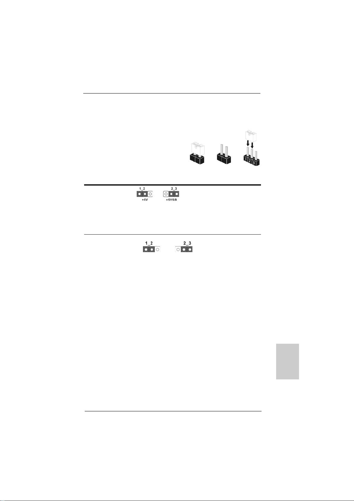
2.5 Einstellung der Jumper2.5 Einstellung der Jumper
2.5 Einstellung der Jumper
2.5 Einstellung der Jumper2.5 Einstellung der Jumper
Die Abbildung verdeutlicht, wie Jumper gesetzt
werden. Werden Pins durch Jumperkappen
verdeckt, ist der Jumper “gebrückt”. Werden
keine Pins durch Jumperka ppen verde ckt, ist
der Jumper “offen”. Die Abbildung zeigt einen
3-Pin Jumper dessen Pin1 und Pin2 “gebrückt”
sind, bzw. es befindet sich e ine Jumper-Kappe
auf diesen beiden Pins.
Jumper Einstellun
PS2_USB_PW1 Überbrücken Sie Pin2, Pin3, um
(siehe S.2, Punkt 1) +5VSB (Standby) zu setzen
Hinweis: Um +5VSB nutzen zu können, muss das Netzteil auf dieser Leitung 2A
oder mehr leisten können.
CMOS löschen
(CLRCMOS1, 3-Pin jumper)
(siehe S.2 - Nr. 17)
DefaultEinstellung
Hinweis: CLRCMOS1 erlaubt Ihnen das Löschen der CMOS-Daten. Diese beinhalten
das System-Passwort, Datum, Zeit und die verschiedenen BIOS-Parameter.
Um die Systempara meter zu löschen und auf die Werk seinstellung
zurückzusetzen, schalten Sie bitte den Computer ab und entfernen da s
Stromkabel. Benutzen Sie eine Jumperkappe, um die Pin 2 und Pin 3 an
CLRCMOS1 für 5 Sekunden kurzzuschließen. Bitte vergessen Sie nicht,
den Jumper wieder zu entfernen, nachdem das CMOS gelöscht wurde. Bitte
vergessen Sie nicht, den Jumper wieder zu entfernen, nachde m da s CMOS
gelöscht wurde. W enn Sie den CMOS-Inhalt gleich n a ch de m Aktualisieren
des BIOS löschen müssen, müssen Sie zuerst da s System starten und
dann wieder ausschalten, bevor Sie den CMOS-Inhalt löschen.
Gebrückt Offen
und die PS/2 oder USBWe ckfunktionen zu aktivieren.
CMOS
löschen
ASRock ALiveNF6P-VSTA Motherboard
5757
57
5757
DeutschDeutsch
DeutschDeutsch
Deutsch
Page 58

2.6 Anschlüsse2.6 Anschlüsse
2.6 Anschlüsse
2.6 Anschlüsse2.6 Anschlüsse
Anschlussleisten sind KEINE Jumper. Setzen Sie KEINE Jumperkappen
auf die Pins der Anschlussleisten. Wenn Sie die Jumperkappen auf die
Anschlüsse setzen, wird das Motherboard permanent beschädigt!
Anschluss Beschreibung
Anschluss für das
Floppy-Laufwerk
(33-Pin FLOPPY1)
(siehe S.2, Punkt 18)
die rotgestreifte Seite auf Stift 1
Hinweis: Achten Sie darauf, dass die rotgestreifte Seite des Ka bel mit der Stift 1-
Seite des An schlusses verbunden wird.
Primärer IDE-Anschluss (blau)
(39-pin IDE1, siehe S.2 - No. 7)
Blauer Anschluss Schwarzer Anschluss
zum Motherboard zur Festplatte
80-adriges ATA 66/100/133 Kabel
Hinweis: Details entnehmen Sie bitte den Anweisungen Ihres IDE-Gerätehändlers.
Deutsch
DeutschDeutsch
DeutschDeutsch
5858
58
5858
Seriell-ATAII-Anschlüsse
(SATAII_1 (PORT0): siehe S.2, Punkt 11)
(SATAII_2 (PORT1): siehe S.2, Punkt 12)
(SATAII_3 (PORT2): siehe S.2, Punkt 13)
(SATAII_4 (PORT3): siehe S.2, Punkt 14)
SATAII_1 (PORT0)
SATAII_2 (PORT1)
SATAII_3 (PORT2)
Diese vier Serial ATA
(SATA II) -Anschlüsse
unterstützen interne SATAoder SATA II-Festplatten. Die
aktuelle SATAII-Schnittstelle
ermöglicht eine
Datenübertragungsrate bis
SATAII_4 (PORT3)
3,0 Gb/s.
Serial ATA- (SATA-) Sie können beide Enden des
Datenkabel SATA-Datenkabels entweder
(Option) mit der SATA / SAT AII-
Festplatte oder
dem SATAII-Anschluss am
Mainboard verbinden.
ASRock ALiveNF6P-VSTA Motherboard
Page 59

l ATA
hlüsse
Serial A TA- (SATA-) Verbinden Sie das schwarze
Stromversorgungskabel Ende des SATA-Netzkabels mit
(Option) dem Netzan schluss am
Verbindung zum
SATA-HDD-Stromanschluss
Verbindung zum
Netzteil
Laufwerk. Verbinden Sie dann
das weiße Ende des SATAStromversorgungskabels mit
dem Stromanschluss des
Netzteils.
USB 2.0-Header Zusätzlich zu den sechs
(9-pol. USB6_7) üblichen USB 2.0-Ports an den
(siehe S.2 - Nr. 16) I/O-Anschlüssen befinden sich
ein USB 2.0-Anschlussleisten
am Motherboard. Pro USB 2.0Anschlussleiste werden zwei
USB 2.0-Ports unterstützt.
WiFi/E Sockel Dieser Sockel unterstützt
(15-pol. WIFI/E) WiFi+AP Funktion mit ASRock
(siehe S.2 - No. 20) WiFi-802.11g oder WiFi-802.11n
Modul, einem einfa ch zu
bedienenden Wireless Local
Area Network (WLAN) Adapter.
Damit sind Sie in der Lage, ein
drahtloses Netzwerk aufzubauen
und die Vorzüge dra htloser
Anschlussmöglichkeiten zu
genießen.
Schnittstelle
ngsrate bis
DeskExpress heißer Stecker Diese Kopf unterstützt die
Detektionskopf heiße Stecker
(5-pin IR1) Untersuchungsfunktion für
(siehe S.2 - Nr. 21) ASRock DeskExpre ss.
Interne Audio-Anschlüsse Diese ermöglichen Ihnen Stereo-
(4-Pin CD1) Signalquellen, wie z. B. CD-ROM,
(CD1: siehe S.2, Punkt 23) DV D-ROM, TV -Tuner oder
CD1
MPEG-Karten mit Ihrem System
zu verbinden.
ASRock ALiveNF6P-VSTA Motherboard
5959
59
5959
DeutschDeutsch
DeutschDeutsch
Deutsch
Page 60

Anschluss für Audio auf Dieses Interface zu eine m
der Gehäusevorderseite Audio-Panel auf der Vorderseite
(9-Pin HD_AUDIO1) Ihres Gehäuses, ermöglicht
(siehe S.2, Punkt 24) Ihnen eine bequeme
Kontrolle über Audio-Geräte.
1. High Definition Audio unterstützt Jack Sensing (automatische Erkennung
falsch angeschlossener Geräte), wobei jedoch die Bildschirmverdrahtung
am Gehäuse HDA unterstützen muss, um richtig zu funktionieren.
Beachten Sie bei der Installation im System die Anweisungen in unserem
Handbuch und im Gehäusehandbuch.
2. Wenn Sie die AC’97-Audioleiste verwenden, installieren Sie diese wie
nachstehend beschrieben an der Front-Audioanschlussleiste:
A. Schließen Sie Mic_IN (MIC) an MIC2_L an.
B. Schließen Sie Audio_R (RIN) an OUT2_R und Audio_L (LIN) an
OUT2_L an.
C. Schließen Sie Ground (GND) an Ground (GND) an.
D. MIC_RET und OUT_RET sind nur für den HD-Audioanschluss
gedacht. Diese Anschlüsse müssen nicht an die AC’97-Audioleiste
angeschlossen werden.
E. Rufen Sie das BIOS-Setup-Dienstprogramm auf. Wechseln Sie zu
Erweiterte Einstellungen und wählen Sie Chipset-Konfiguration.
Setzen Sie die Option Frontleistenkontrolle von [Automatisch] auf
[Aktiviert].
F. Rufen Sie das Windows-System auf. Klicken Sie auf das Symbol in der
Taskleiste unten rechts, um den Realtek HD Audio-Manager aufzurufen.
Für Windows® 2000 / XP / XP 64-Bit Betriebssystem:
Klicken Sie auf “Audio-E/A”, wählen Sie die “Anschlusseinstellungen”
, wählen Sie “Erkennung der Frontleistenbuchse
Deutsch
DeutschDeutsch
DeutschDeutsch
6060
60
6060
deaktivieren” und speichern Sie die Änderung durch Klicken auf “OK”.
Für Windows® Vista
Die Rechtoberseite „Dateiordner“ Ikone anklicken , „Schalttafel
Buchse Entdeckung sperren“ wählen und die Änderung speichern,
indem Sie „OKAY“ klicken.
TM
/ VistaTM 64-Bit Betriebssystem:
System Panel An schluss Dieser Anschluss ist für die
(9-Pin PANEL1) verschiedenen Funktionen der
(siehe S.2, Punkt 15) Gehäusefront.
ASRock ALiveNF6P-VSTA Motherboard
Page 61

Gehäuselautsprecher-Header Schließen Sie den
(4-pin SPEAKER1) Gehäuselautsprecher an
(siehe S.2, Punkt 10) diesen Header an.
Gehäuse-Lüfteranschluss Verbinden Sie das
(3-pin CHA_FAN1) Gehäuselüfterkabel mit diesem
(siehe S.2, Punkt 3) Anschluss und passen Sie den
schwarzen Draht dem
Erdungsstift an.
CPU-Lüfteranschluss Verbinden Sie das CPU -
(4-pin CPU_FAN1) Lüfterkabel mit diesem
(siehe S.2, Punkt 28) Anschluss und passen Sie den
4
3
2
1
schwarzen Draht dem
Erdungsstift an.
Obwohl dieses Motherboard einen vierpoligen CPU-Lüfteranschluss (Quiet Fan)
bietet, können auch CPU-Lüfter mit dreipoligem Anschluss angeschlossen
werden; auch ohne Geschwindigkeitsregulierung. Wenn Sie einen dreipoligen
CPU-Lüfter an den CPU-Lüferanschluss dieses Motherboards anschließen
möchten, verbinden Sie ihn bitte mit
den Pins 1 – 3.
ATX-Netz-Hea der Verbinden Sie die A TX-
(24-pin ATXPWR1) Stromversorgung mit diesem
(siehe S.2, Punkt 27) Header.
Lüfter mit dreipoligem Anschluss installieren
1
13
12
24
Obwohl dieses Motherboard einen 24-pol. ATX-Stromanschluss
bietet, kann es auch mit einem modifizierten traditionellen 20-pol.
ATX-Netzteil verwendet werden. Um ein 20-pol. ATX-Netzteil zu
verwenden, stecken Sie den Stecker mit Pin 1 und Pin 13 ein.
Installation eines 20-pol. ATX-Netzteils
Pins 1–3 anschließen
13
24
1
12
ASRock ALiveNF6P-VSTA Motherboard
6161
61
6161
DeutschDeutsch
DeutschDeutsch
Deutsch
Page 62
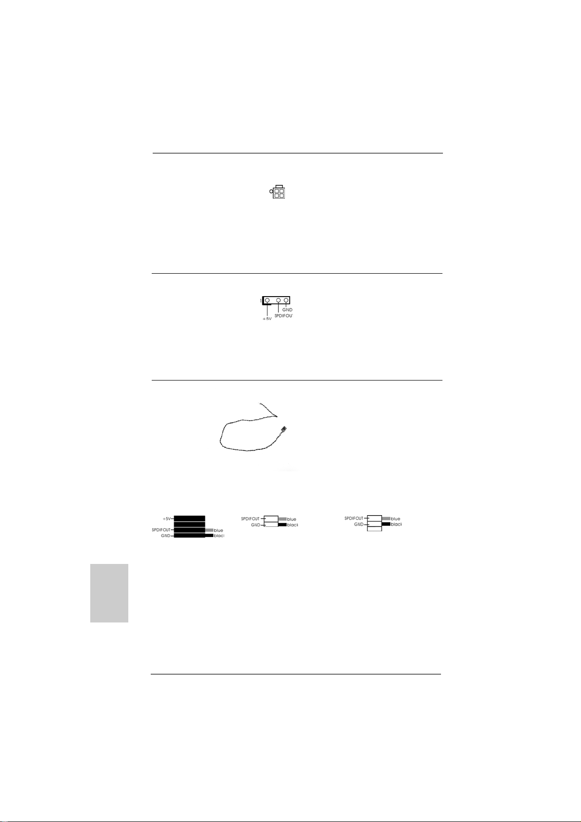
Anschluss für Beachten Sie bitte, dass Sie eine
12V-ATX-Netzteil Stromversorgung mit ATX 12-
(4-pin ATX12V1) Volt-Stecker mit diese m
(siehe S.2, Punkt 2) Anschluss verbinden müssen,
damit ausreichend Strom
geliefert werden kann.
Andernfalls reicht der Strom
nicht aus, das System zu starten.
HDMI_SPDIF-Anschluss Der HDMI_SPDIF-Anschluss
(HDMI_SPDIF1, dreipolig) stellt einen SPDIF-
(siehe S.2 - No. 19) Audioausgang für eine HDMI-
VGA-Karte zur Verfügung und
ermöglicht den Anschluss von
HDMI-Digitalgeräten wie
Fernsehgeräten, Projektoren,
LCD-Geräten an das System.
HDMI_SPDIF-Kabel Bitte verbinden Sie das
(Option) schwarze Ende (A) des
C
B
A
HDMI_SPDIF-Kabels mit dem
HDMI_SPDIF-Anschluss am
Motherboard. Schließen Sie
dann das weiße Ende (B oder
C) des HDMI_SPDIF-Kabels an
den HDMI_SPDIF-Anschluss der
HDMI-VGA-Karte an.
Deutsch
DeutschDeutsch
DeutschDeutsch
6262
62
6262
A. Schwarzes Ende B. Weißes Ende (zweipolig) C. Weißes Ende (dreipolig)
ASRock ALiveNF6P-VSTA Motherboard
Page 63

2.72.7
HDMI_SPDIFHDMI_SPDIF
2.7
HDMI_SPDIF
2.72.7
HDMI_SPDIFHDMI_SPDIF
HDMI (Hochauflösende Multimedia-Schnittstelle) ist eine komplett digitale Audio/
Video-Spezifikation, die eine Schnittstelle zwischen sämtlichen kompatiblen
Digitalaudio-/Videoquellen zur Verfügung stellt. Beispiele für solche Digitalgeräte
sind Digitalempfänger , DV D-Player, A/V-Re ceiver sowie kompatible Audiosysteme
und Videoanzeigegeräte zum digitalen Fernsehen (DTV). Ein komplettes HDMISystem benötigt eine HDMI-VGA-Karte und ein HDMI-kompatibles Motherboard mit
verbundenem HDMI_SPDIF-Anschluss. Ihr Motherboard ist mit einem HDMI_SPDIFAnschluss ausgestattet, der einen SPDIF-Audioausgang für eine HDMI-VGA-Karte
zur Verfügung stellt und den Anschluss von HDMI-Digitalgeräten wie
Fernsehgeräten/Projektoren/LCD-Geräten an das System ermöglicht. Um die HDMIFunktionen Ihres Motherboards nutzen zu können, führen Sie bitte die
nachstehenden Schritte aus.
Schritt 1: Installieren Sie die HDMI-VGA-Karte i m PCI Express-Steckplatz Ihres
Motherboards. Hinweise zur Installation der HDMI-VGA-Karte finden Sie
in der Installationsanleitung auf Seite 54.
Schritt 2: Verbinden Sie das schwarze Ende (A) des HDMI_SPDIF-
Kabels mit dem HDMI_SPDIF-Anschluss (HDMI_SPDIF1, gelb,
siehe Seite 2, Nr. 19) am Motherboard.
Achten Sie darauf, dass das HDMI_SPDIF-Kabel richtig an Motherboard und HDMIVGA-Karte a nge schlossen wird; be achten Sie die jeweilige Pinbelegung. Hinweise zur
Pinbelegung des HDMI_SPDIF-Anschlusses sowie der Stecker am HDMI_SPDIF-Kabel
finden Sie auf Seite 62. Die Pinbelegung des HDMI_SPDIF-Anschlusses finden Sie
in der Dokumentation Ihrer HDMI-VGA-Karte. Anschlussfehler können Motherboard
und HDMI-VGA-Karte irreparabel beschädigen.
Schritt 3: Schließen Sie das weiße Ende (B oder C) des HDMI_SPDIF-Kabels an
den HDMI_SPDIF-Anschluss der HDMI-V GA-Karte a n. Am HDMI_SPDIFKabel befinden sich zwei weiße Enden (zwei- und dreipolig). Bitte
wählen Sie das zum HDMI_SPDIF-Anschluss Ihrer VGA-Karte passende
weiße Ende aus.
--
Anschluss – InstallationshinweiseAnschluss – Installationshinweise
-
Anschluss – Installationshinweise
--
Anschluss – InstallationshinweiseAnschluss – Installationshinweise
Weiße s Ende
(zweipolig) (B)
Schließen Sie das weiße Ende des HDMI_SPDIF-Kabels keinesfalls an
den falschen Anschluss der HDMI-VGA-Karte oder gar an eine andere
VGA-Karte an. Dadurch können Motherboard und VGA-Karte schwer
beschädigt werden. In der Abbildung sehen Sie ein Beispiel für einen
falschen Anschluss: Hier wird versucht, das HDMI_SPDIF-Kabel mit dem
Lüfteranschluss der PCI Express-VGA-Karte zu verbinden. Schauen Sie in die
Dokumentation Ihrer VGA-Karte und informieren Sie sich schon im Vorfeld über die
richtige Nutzung der Anschlüsse.
ASRock ALiveNF6P-VSTA Motherboard
Weiße s Ende
(dreipolig) (C)
6363
63
6363
DeutschDeutsch
DeutschDeutsch
Deutsch
Page 64

Schritt 4: Schließen Sie den HDMI-Ausgang an ein HDMI-Gerät an; z. B.
an ein HDTV-Gerät. Hinweise zum richtigen Anschluss finden
Sie in der Dokumentation des HDMI-Gerätes und der VGA-Karte.
Schritt 5: Installieren Sie die HDMI-VGA-Kartentreiber in Ihrem System.
2.82.8
Anleitung zur SAAnleitung zur SA
2.8
Anleitung zur SA
2.82.8
Anleitung zur SAAnleitung zur SA
Bevor Sie eine SA TA II Fe stplatte in Ihre m Computer installieren, lesen Sie bitte die
folgende Anleitung zur SATA II Festplatteneinrichtung aufmerksam durch. Einige
Standardeinstellungen von SATA II Festplatten sind möglicherweise nicht in den
SATA II Modus geschaltet und arbeiten daher nicht mit optimaler Leistung. Um die
SATA II Funktionalität zu aktivieren, führen Sie bitte die nachstehenden Schritte für
Festplatten unterschiedlicher Hersteller aus und stellen Ihre SATA II Festplatte
schon vorher auf den SATA II Modus um; andernfalls kann es vorkommen, dass
Ihre SATA II Festplatte nicht im SATA II-Modus arbeitet.
Western Digital
Falls die Pins 5 und 6 verbunden werden, wird SATA mit 1,5 Gb/s aktiviert.
Wenn Sie andererseits SATA II mit 3,0 Gb/s aktivieren möchten, ziehen Sie bitte die
Steckbrücke (Jumper) von den Pins 5 und 6 ab.
SAMSUNG
TT
A II FA II F
T
A II F
TT
A II FA II F
estplatteneinrichtungestplatteneinrichtung
estplatteneinrichtung
estplatteneinrichtungestplatteneinrichtung
Deutsch
DeutschDeutsch
DeutschDeutsch
6464
64
6464
Falls die Pins 3 und 4 verbunden werden, wird SATA mit 1,5 Gb/s aktiviert.
Wenn Sie andererseits SATA II mit 3,0 Gb/s aktivieren möchten, ziehen Sie bitte die
Steckbrücke (Jumper) von den Pins 3 und 4 ab.
HITACHI
Zum Ändern verschiedener ATA-Funktionen benutzen Sie bitte das Feature Tool –
ein unter DOS ausführbares Dienstprogra mm. Auf der Internetseite von HITACHI
finden Sie entsprechende Details:
http://www.hitachigst.com/hdd/support/download.htm
Die Beispiele oben dienen lediglich Ihrer Referenz. Die
Steckbrückeneinstellungen können bei unterschiedlichen SATA II Festplatten
verschiedener Hersteller abweichen. Aktualisierungen und ergänzende
Informationen finden Sie auf der Internetseite des Herstellers.
ASRock ALiveNF6P-VSTA Motherboard
Page 65

2.92.9
Serial ASerial A
2.9
Serial A
2.92.9
Serial ASerial A
FestplatteninstallationFestplatteninstallation
Festplatteninstallation
FestplatteninstallationFestplatteninstallation
Dieses Motherboard adoptiert NVIDIA® GeForce 6150SE / nForce 430-Chi pset, da s
serielle ATA (SA T A) / serielle ATAII (SA TAII)-Festplatten und RAID unterstützt. Sie
können mit diesem Motherboard SA TA / SAT AII-Festplatten als internes
Speichermedium verwenden. Dieses Ka pitel ze igt Ihnen, wie SA TA / SAT AIIFestplatten installiert werden.
SCHRITT 1: Installieren Sie die SATA / SATAII-Festplatten in den
SCHRITT 2: Verbinden Sie das SATA-Netzkabel mit der SATA / SATAII-Festplatte.
SCHRITT 3: Schließen Sie ein Ende des SATA-Datenkabels am SATA / SATAII-
SCHRITT 4: Schließen Sie das andere Ende des SATA-Datenkabels an die SATA /
2.102.10
Hot-Plug- und Hot-Swap-FHot-Plug- und Hot-Swap-F
2.10
Hot-Plug- und Hot-Swap-F
2.102.10
Hot-Plug- und Hot-Swap-FHot-Plug- und Hot-Swap-F
FestplattenFestplatten
Festplatten
FestplattenFestplatten
Das Motherboard ALiveNF6P-VSTA unterstützt Hot-Plug-Funktion für SATA / SA TAII-
Geräte.
TT
AA
- (SA- (SA
TT
- (SA
- (SA- (SA
T
TT
A) / Serial AA) / Serial A
A) / Serial A
A) / Serial AA) / Serial A
T
A
TT
AA
Laufwerkseinschüben des Gehäuses.
Anschluss des Motherboards an.
SATAII-Festplatte an.
HIN WEIS
Was ist die Hot-Plug-Funktion?
Wenn SATA / SATAII-Festplatten NICHT für RAID-Konfiguration
eingestellt sind, werden sie “Hot-Plug” genannt: Ein Einfügen und
Entfernen von SATA / SATAII-Festplatten, während das System in
Betrieb ist und einwandfrei läuft.
TT
AII- (SAAII- (SA
T
AII- (SA
TT
AII- (SAAII- (SA
unktion für SAunktion für SA
unktion für SA
unktion für SAunktion für SA
TT
T
TT
AII)AII)
AII)
AII)AII)
TT
T
TT
A / SAA / SA
A / SA
A / SAA / SA
TT
AII-AII-
T
AII-
TT
AII-AII-
Was ist die Hot-Swap-Funktion?
Wenn SATA / SATAII-Festplatten als RAID1 oder RAID5 eingebaut
sind, werden sie “Hot-Swap” genannt: Ein Einfügen und Entfernen
von SATA / SATAII-Festplatten, während das System in Betrieb ist
und einwandfrei läuft.
2.112.11
TT
2.11
2.112.11
Zur Treiberinstallation Sie bitte die Unterstützungs-CD in Ihr optisches Laufwerk
ein. Anschließend werden die mit Ihrem System kompatiblen Treiber automatisch
erkannt und auf dem Bildschirm angezeigt. Zur Installation der nötigen Treiber
gehen Sie bitte der Reihe nach von oben nach unten vor. Nur so können die von
Ihnen installierten Treiber richtig arbeiten.
reiberinstallationreiberinstallation
T
reiberinstallation
TT
reiberinstallationreiberinstallation
ASRock ALiveNF6P-VSTA Motherboard
6565
65
6565
DeutschDeutsch
DeutschDeutsch
Deutsch
Page 66

2.12 Installation von Windows2.12 Installation von Windows
2.12 Installation von Windows
2.12 Installation von Windows2.12 Installation von Windows
TMTM
TM
TMTM
Vista Vista
Vista
Vista Vista
Wenn Sie auf Ihren SAT A / SATAII-Festplatten lediglich Windows® 2000, Windows
XP, Windows® XP 64-Bit, Windows® VistaTM, Windows® VistaTM 64-Bit ohne RAIDFunktionen installieren möchten, ist das Anlegen e iner SAT A / SAT AII-T re iberdiskette
nicht erforderlich. Außerde m brauchen Sie die BIOS-Einstellungen nicht zu ändern.
Sie können Windows® 2000, Windows® XP, Windows® XP 64-Bit, Windows® VistaTM,
Windows® VistaTM 64-Bit direkt auf Ihr System installieren.
/ Vista / Vista
/ Vista
/ Vista / Vista
TMTM
TM
TMTM
64-Bit ohne RAID 64-Bit ohne RAID
64-Bit ohne RAID
64-Bit ohne RAID 64-Bit ohne RAID
®
2000 / XP / XP 64-Bit / 2000 / XP / XP 64-Bit /
2000 / XP / XP 64-Bit /
2000 / XP / XP 64-Bit / 2000 / XP / XP 64-Bit /
-F-F
unktionenunktionen
-F
unktionen
-F-F
unktionenunktionen
®
Deutsch
DeutschDeutsch
DeutschDeutsch
2.132.13
Installation von WindowsInstallation von Windows
2.13
Installation von Windows
2.132.13
Installation von WindowsInstallation von Windows
TMTM
TM
TMTM
VistaVista
Vista
VistaVista
Möchten Sie das Windows® 2000, Windows® XP, Windows® XP 64-Bit, Windows
VistaTM oder Windows® VistaTM 64-Bit Betriebssystem auf Ihre SATA / SATAIIFestplatten mit RAID-Funktionen installieren, dann folgen Sie bitte je nach dem zu
installierenden Betriebssystem den folgenden Schritten.
2.13.1 Installation von Windows2.13.1 Installation von Windows
2.13.1 Installation von Windows
2.13.1 Installation von Windows2.13.1 Installation von Windows
RAID-Funktionen RAID-Funktionen
RAID-Funktionen
RAID-Funktionen RAID-Funktionen
Bitte gehen Sie wie folgt vor, wenn Sie Windows® 2000, Windows® XP,
Windows® XP 64-Bit auf Ihren SATA / SATAII-Festplatten mit RAID-Funktionen
installieren möchten.
SCHRITT 1: Erstellen Sie eine SATA / SATAII-Treiberdiskette.
A. Legen Sie die ASRock Support-CD in Ihr optisches Laufwerk, um Ihr System
hochzufahren. (Legen Sie zu diesem Zeitpunkt KEINE Diskette in das
Diskettenlaufwerk ein!)
B. Während des Selbsttests zu Beginn des Systemstarts drücken Sie die <F11>-
Taste – ein Fenster zur Auswahl des Boot-Laufwerkes (Startlaufwerk)
erscheint. Bitte wählen Sie das CD-ROM-Laufwerk als Boot-Laufwerk.
C. Die Meldung „Generate Serial ATA driver diskette [Y/N]?“
[Serial ATA-Treiberdiskette erstellen [Y/N]?] bestätigen Sie mit <Y>.
/ Vista / Vista
/ Vista
/ Vista / Vista
Sie müssen über SP4 verfügen, ehe Sie Windows 2000 in Ihrem System
installieren. Falls Ihre Windows®-Version noch nicht über SP4 verfügen
sollte, können Sie mit Hilfe der nachstehenden Internetseite einen SP4Datenträger anlegen:
http://www.microsoft.com/Windows2000/downloads/servicepacks/sp4/
spdeploy.htm#the_integrated_installation_fmay
TMTM
TM
TMTM
64-Bit mit RAID-Funktionen 64-Bit mit RAID-Funktionen
64-Bit mit RAID-Funktionen
64-Bit mit RAID-Funktionen 64-Bit mit RAID-Funktionen
®
2000 / XP / XP 64-Bit / 2000 / XP / XP 64-Bit /
2000 / XP / XP 64-Bit /
2000 / XP / XP 64-Bit / 2000 / XP / XP 64-Bit /
®
2000 / XP / XP 64-Bit mit 2000 / XP / XP 64-Bit mit
2000 / XP / XP 64-Bit mit
2000 / XP / XP 64-Bit mit 2000 / XP / XP 64-Bit mit
®
6666
66
6666
ASRock ALiveNF6P-VSTA Motherboard
Page 67

D. Daraufhin werden die Meldungen
Please insert a blank
formatted diskette into floppy
drive A:
press any key to start
(Bitte legen Sie eine leere, formatierte Diskette in Laufwerk A:
ein und drücken Sie zum Beginnen eine beliebige Ta ste.)
Bitte legen Sie eine Dis kette in das Diskettenlaufwerk e in und drücken Sie
eine beliebige Ta ste.
E. Das System beginnt mit dem Formatieren der Diskette und kopiert die SAT A /
SATAII-Treiber auf die Diskette.
SCHRITT 2: Konfigurieren Sie BIOS.
A. Rufen Sie im BIOS-DIENSTPROGRAMM den Bildschirm „Erweitert“ und
„IDE-Konfiguration“ auf.
B. Stellen Sie die Option “SATA-Betriebsmodus” auf [RAID] um.
SCHRITT 3: Verwenden Sie das “RAID Installation Guide”, um die RAID-
Konfiguration einzustellen.
Bevor Sie mit der Konfiguration der RAID-Funktion anfa ngen, sehen Sie bitte in der
Installationsanleitung auf der Support CD für eine richtige Konfiguration na ch. Bitte
lesen Sie die BIOS RAID-Installationsanle itung in dem folgenden Pfa d auf der SupportCD:
.. \ RAID Installation Guide
SCHRITT 4: Installieren Sie Windows® 2000 / Windows® XP / Windows® XP
64-Bit in Ihrem System.
Nach den Schritten 1, 2 und 3 können Sie mit der Installation von Windows® 2000 /
Windows® XP / Windows® XP 64-Bit beginnen. Zu Beginn der Windows®-Einrichtung
drücken Sie die F6-T aste zur Installation eines Dritta nbieter RAID-T reibers. Legen Sie
die Diskette mit dem NVIDIA® RAID-Treiber ein, wenn Sie dazu aufgefordert werden.
Nach dem Einlesen der Diskette wid der entsprechende Tr eiber a ngezeigt. Wählen Sie
den zu installierenden Treiber passend zum gewünschten Modus und zum
Betriebssystem.
HINWEIS:
Wenn Sie Windows® 2000 / Windows® XP / Windows® XP 64-bit auf IDE-Festplatten
installieren und RAID-Funktionen (Erstellen, Konvertieren, Löschen oder
Neuaufbau) mit SATA / SATAII-Festplatten nutzen möchten, müssen Sie dennoch
zunächst den “SATA Operation Mode” (SATA-Betriebsmodus) auf [RAID]
einstellen. Bitte lesen Sie Windows RAID-Installationsanleitung in dem folgenden
Pfad auf der Support-CD, um die RAID-Konfiguration vorzunehmen:
.. \ RAID Installation Guide
ASRock ALiveNF6P-VSTA Motherboard
6767
67
6767
DeutschDeutsch
DeutschDeutsch
Deutsch
Page 68

Vista Vista
Vista
Vista Vista
TMTM
TM
TMTM
/ Vista / Vista
/ Vista
/ Vista / Vista
2.13.2 Installation von Windows2.13.2 Installation von Windows
2.13.2 Installation von Windows
2.13.2 Installation von Windows2.13.2 Installation von Windows
mit RAID mit RAID
mit RAID
mit RAID mit RAID
Bitte gehen Sie wie folgt vor, wenn Sie Windows® VistaTM, Windows® VistaTM 64-Bit
auf Ihren SATA / SAT AII-Festplatten mit RAID-Funktionen in stallieren möchten.
SCHRITT 1: Konfigurieren Sie BIOS.
A. Rufen Sie im BIOS-DIENSTPROGRAMM den Bildschirm „Erweitert“ und
„IDE-Konfiguration“ auf.
B. Stellen Sie die Option “SATA-Betriebsmodus” auf [RAID] um.
SCHRITT 2: Verwenden Sie das “RAID Installation Guide”, um die RAID-
Konfiguration einzustellen.
Bevor Sie mit der Konfiguration der RAID-Funktion anfangen, sehen Sie bitte in der
Installationsanleitung auf der Support CD für eine richtige Konfiguration nach. Bitte
lesen Sie die BIOS RAID-Installationsanleitung in dem folgenden Pfad auf der
Support-CD:
.. \ RAID Installation Guide
SCHRITT 3: Installieren Sie Windows® VistaTM / Windows® Vista
Ihrem System.
Legen Sie Windows® VistaTM / VistaTM 64-Bit optische Disc in das optische
Laufwerk ein, um Ihr System zu starten. Folgen Sie anschließend den
Anweisungen, um das Windows® VistaTM / VistaTM 64-Bit Betriebssystem auf
Ihrem System zu installieren. Wenn die Frage “Wo möchten Sie Windows
installieren?” erscheint, legen Sie bitte die ASRock Support CD in Ihr optisches
Laufwerk ein. Klicken Sie anschließend die “T reiber la den”-Schaltfläche links unten,
um die NVIDIA® RAID-Treiber zu installieren. Die NVIDIA® RAID-Treiber befinden sich
in dem folgenden V erzeichnis auf der Support CD:
.. \ I386 \ Vista (Für Windows® VistaTM-Benutzer)
.. \ AMD64 \ Vista64 (Für Windows® VistaTM 64-Bit Benutzer)
Legen Sie danach noch einmal die Windows® VistaTM / VistaTM 64-Bit optische Disc in
das optische Laufwerk, um die Installation f ortzusetzen.
-F-F
unktionenunktionen
-F
unktionen
-F-F
unktionenunktionen
®
TMTM
TM
TMTM
64-Bit 64-Bit
64-Bit
64-Bit 64-Bit
TM
64-Bit in
Deutsch
DeutschDeutsch
DeutschDeutsch
6868
68
6868
HINWEIS:
Wenn Sie Windows® VistaTM / Windows® VistaTM 64-Bit auf IDE-Festplatten
installieren und RAID-Funktionen (Erstellen, Konvertieren, Löschen oder
Neuaufbau) mit SATA / SATAII-Festplatten nutzen möchten, müssen Sie dennoch
zunächst den “SATA Operation Mode” (SATA-Betriebsmodus) auf [RAID]
einstellen. Bitte lesen Sie Windows RAID-Installationsanleitung in dem folgenden
Pfad auf der Support-CD, um die RAID-Konfiguration vorzunehmen:
.. \ RAID Installation Guide
ASRock ALiveNF6P-VSTA Motherboard
Page 69

2.142.14
Entkoppelte ÜbertaktungstechnologieEntkoppelte Übertaktungstechnologie
2.14
Entkoppelte Übertaktungstechnologie
2.142.14
Entkoppelte ÜbertaktungstechnologieEntkoppelte Übertaktungstechnologie
(Untied Overclocking T(Untied Overclocking T
(Untied Overclocking T
(Untied Overclocking T(Untied Overclocking T
Dieses Motherboard unterstützt die Entkoppelte Übertaktungstechnologie, durch
die der FSB durch fixierte PCI-/PCIE-Busse beim Übertakten effektiver arbeiten.
Bevor Sie die Entkoppelte Übertaktung aktivieren, stellen Sie bitte die Option
“Overclock Mode” (Übertaktungsmodus) im BIOS von [Auto] auf [CPU, PCIE,
Async.] um. Dadurch wird der CPU-FSB beim Übertakten entkoppelt, PCI- und
PCIE-Busse werden jedoch fixiert, so dass der FSB in einer stabileren
Übertaktungsumgebung arbeiten kann.
Beziehen Sie sich auf die Warnung vor möglichen Overclocking-Risiken auf Seite
49, bevor Sie die Untied Overclocking-Technologie anwenden.
3. BIOS-Information3. BIOS-Information
3. BIOS-Information
3. BIOS-Information3. BIOS-Information
Das Flash Memory dieses Motherboards speichert das Setup-Utility. Drücken Sie
<F2> während des POST (Power-On-Self-Test) um ins Setup zu gela ngen, ansonsten
werden die Testroutinen weiter abgearbeitet. Wenn Sie ins Setup gelangen wollen,
nachdem der POST durchgeführt wurde, müssen Sie das System über die
Tastenkombination <Ctrl> + <Alt> + <Delete> oder den Reset-Knopf auf der
Gehäusevorderseite, neu starten. Natürlich können Sie einen Neustart auch durchführen,
indem Sie das Syste m kurz ab- und da na ch wieder a nschalten. Da s Setup-Progra mm ist
für eine bequeme Bedienung entwickelt worden. Es ist ein menügesteuertes Progra mm,
in dem Sie durch unterschiedliche Untermenüs scrollen und die vorab festgelegten
Optionen auswählen können. Für detaillierte Informationen zum BIOS-Setup, siehe bitte
das Benutzerha ndbuch (PDF Datei) auf der Support CD.
echnology)echnology)
echnology)
echnology)echnology)
4. Software Suppor4. Software Suppor
4. Software Suppor
4. Software Suppor4. Software Suppor
Dieses Motherboard unterstützt eine Reiche von Microsoft® Windows
Betriebssystemen: 2000 / XP / XP Media Center / XP 64-Bit / VistaTM / VistaTM 64-Bit.
Die Ihrem Motherboard beigefügte Support-CD enthält hilfreiche Software, Treiber und
Hilfsprogra mme, mit denen Sie die Funktionen Ihres Motherboards verbessern können
Legen Sie die Support-CD zunächst in Ihr CD-ROM-Laufwerk ein. Der
Willkommensbildschirm mit den Installationsmenüs der CD wird automatisch
aufgerufen, wenn Sie die “Autorun”-Funktion Ihres Systems aktiviert haben.
Erscheint der Wilkommensbildschirm nicht, so “doppelklicken” Sie bitte auf das File
ASSETUP.EXE im BIN-Verzeichnis der Support-CD, um die Menüs aufzurufen.
Das Setup-Progra mm soll es Ihnen so le icht wie möglich ma chen. Es ist menügesteuert,
d.h. Sie können in den verschiedenen Untermenüs Ihre Auswahl treffen und die
Programme werden dann automatisch installiert.
ASRock ALiveNF6P-VSTA Motherboard
t CD informationt CD information
t CD information
t CD informationt CD information
®
6969
69
6969
DeutschDeutsch
DeutschDeutsch
Deutsch
Page 70

1. Introduction1. Introduction
1. Introduction
1. Introduction1. Introduction
Merci pour votre achat d’une carte mère ASRock ALiveNF6P-VSTA, une carte mère
très fiable produite selon les critères de qualité rigoureux de ASRock. Elle offre des
performances excellentes et une conception robuste conformément à l’engagement
d’ASRock sur la qualité et la fiabilité au long terme.
Ce Guide d’installation rapide présente la carte mère et constitue un guide
d’installation pas à pas. Des informations plus détaillées concernant la carte mère
pourront être trouvées dans le manuel l’utilisateur qui se trouve sur le CD
d’assistance.
Les spécifications de la carte mère et le BIOS ayant pu être mis à
jour, le contenu de ce manuel est sujet à des changements sans
notification. Au cas où n’importe qu’elle modification intervenait sur ce
manuel, la version mise à jour serait disponible sur le site web
ASRock sans nouvel avis. Vous trouverez les listes de prise en
charge des cartes VGA et CPU également sur le site Web ASRock.
Site web ASRock, http://www.asrock.com
Si vous avez besoin de support technique en relation avec cette carte
mère, veuillez consulter notre site Web pour de plus amples
informations particulières au modèle que vous utilisez.
www.asrock.com/support/index.asp
1.11.1
Contenu du paquetContenu du paquet
1.1
Contenu du paquet
1.11.1
Contenu du paquetContenu du paquet
Carte mère ASRock ALiveNF6P-VSTA
(Facteur de forme M icro ATX: 9.6 pouce s x 7.7 pouces, 24.4 cm x 19.6 cm)
Guide d’installation ra pide ASRock ALiveNF6P-VSTA
CD de soutien ASRock ALiveNF6P-VSTA
Un câble ruba n IDE Ultra AT A 66/100/133 80 conducteurs
Un câble ruba n pour un lecteur de dis quettes 3,5 pouces
Un câble de données Serial AT A (SAT A) (Optionnelle)
Un cordon d’alimentation DD série AT A (SA T A) (Optionnelle)
Un écra n “ASRock 6CH I/O Plus”
F
FF
FF
rançais
rançaisrançais
rançaisrançais
7070
70
7070
ASRock ALiveNF6P-VSTA Motherboard
Page 71

1.21.2
SpécificationsSpécifications
1.2
Spécifications
1.21.2
SpécificationsSpécifications
Format - Facteur de forme M icro A TX:
9.6 pouces x 7.7 pouces, 24.4 cm x 19.6 cm
CPU - Socket AM2 prena nt en charge le proce sseur AMD Phenom
X4 / X2, Athlon 64FX / 64X2 / X2 / 64 et Sempron
- Prêt AMD LIVE!
- Supporte la technologie Cool ‘n’ Quiet™ d’AMD
- FSB 1000 MHz (2.0 GT/s)
- Prend en charge la technologie Untied Overclocking
(voir ATTENTION 1)
- Prise en charge de la technologie Hyper Tra nsport
Chipsets - NVIDIA® GeForce 6150SE / nForce 430
Mémoire - Compatible avec la Technologie de Mémoire à Ca nal Double
(voir A TTENTION 2)
- 2 x slots DIMM DDRII
- Supporte DDRII1066/800/667/533 (voir A TTENTION 3)
- Max. 4Go (voir ATTENTION 4)
L’accélérateur - Contrôle direct de la fréquence CPU (voir ATTENTION 5)
hybride - ASRock U-COP (voir A TTENTION 6)
- Garde d’échec au démarrage (B.F.G.)
- ASRock AM2 Boost: Technologie brevetée par ASRock pour
augmenter les performances mémoire jus qu’à 12,5%
(voir ATTENTION 7)
Slot d’extension - 1 x slot PCI Express x16
- 1 x slot PCI Express x1
- 2 x slots PCI
VGA sur carte - NVIDIA® graphique cla sse GeForce6 intégré
- DX9.0 VGA, nuanceur de pixels 3.0
- mémoire partagée max 256 MB
Audio - 5.1 Son haute définition de première qualité CH Windows
VistaTM (codec audio ALC662)
LAN - Realtek PHY RTL8201CL
- Vitesse: 10/100 Ethernet
- Support du Wa ke-On-LAN
Panneau arrière ASRock 6CH I/O Plus
E/S - 1 x port souris PS/2
- 1 x port clavier PS/2
- 1 x port série: COM1
- 1 x port VGA
- 1 x port parallèle: Support ECP/EPP
- 6 x ports USB 2.0 par défaut
ASRock ALiveNF6P-VSTA Motherboard
TM
®
TM
çaisçais
çaisçais
çais
ranran
ranran
ran
FF
FF
F
7171
71
7171
Page 72

F
FF
FF
rançais
rançaisrançais
rançaisrançais
- 1 x port RJ-45
- Jack audio: entrée ligne / sortie ligne / microphone
Connecteurs - 4 x connecteurs SATAII, prennent en charge un taux de
transfert de données pouvant aller jusqu’à 3.0Go/s,
supporte RAID (RAID 0, RAID 1, RAID 0+1, RAID 5 et JBOD),
NCQ et “Hot-Plug” (Connexion à chaud)
(voir A TTENTION 8)
- 1 x ATA133 IDE connecteurs
(prend en charge jusqu’à 2 périphériques IDE)
- 1 x Port Disquette
- 1 x DeskExpress Hot Plug Detection header
- 1 x Connecteur HDMI_SPDIF
- Connecteur pour ventilateur de CPU/Châssis
- br. 24 connecteur d’ali mentation ATX
- br. 4 connecteur d’alimentation 12V ATX
- Connecteurs audio internes
- Connecteur audio panneau avant
- 1 x En-tête USB 2.0 (prendre en charge 2 ports USB 2.0
supplémentaires) (voir ATTENTION 9)
- 1 x En-tête WiFi/E (voir ATTENTION 10)
BIOS - 4Mb BIOS AMI
- BIOS AMI
- Support du “Plug and Play”
- Compatible pour événements de réveil ACPI 1.1
- Gestion jumperless
- Support SMBIOS 2.3.1
CD d’assistance - Pilotes, utilitaires, logiciel anti-virus (Version d’essai)
Surveillance - Déte ction de la température de l’UC
système - Mesure de température de la carte mère
- T a chéomètre ventilateur CPU
- Tachéomètre ventilateur châssis
- Ventilateur silencieux d’unité centrale
- Monitoring de la tension: +12V, +5V, +3.3V, Vcore
OS - Microsoft® Windows® 2000 / XP / XP Media Center / XP 64-bit
Certifications - FCC, CE, WHQL
/ Vista
TM
/ VistaTM 64-bit
7272
72
7272
ASRock ALiveNF6P-VSTA Motherboard
Page 73

A TTENTION
Il est important que vous réalisiez qu’il y a un certain risque à effectuer l’overclocking, y
compris ajuster les réglages du BIOS, appliquer la technologie Untied Overclocking, ou
utiliser des outils de tiers pour l’overclocking. L’overclocking peut affecter la stabilité de
votre système, ou même causer des dommages aux composants et dispositifs de votre
système. Si vous le faites, c’est à vos frais et vos propres risques. Nous ne sommes
pas responsables des dommages possibles causés par l’overclocking.
ATTENTION!
1. Cette carte mère prend en charge la technologie Untied Overclocking.
Veuillez lire “La technologie de surcadençage à la volée” à la page 92
pour plus d’informations.
2. Cette carte mère supporte la Technologie de Mémoire à Canal
Double. Avant d’intégrer la Technologie de Mémoire à Canal Double,
assurez-vous de bien lire le guide d’installation des modules
mémoire en page 76 pour réaliser une installation correcte.
3. La prise en charge de fréquences de mémoire de 1066MHz dépend
du CPU AM2+ que vous choisissez. La spécification DDRII1066 étant
hors de la norme de mémoire JEDEC, si vous choisissez des
barrettes de mémoire DDRII1066 sur cette carte mère, veuillez vous
référer à la liste des mémoires prises en charge sur notre site Web
pour connaître barrettes de mémoire compatibles.
Site Web ASRock
4. Du fait des limites du système d’exploitation, la taille mémoire réelle
réservée au système pourra être inférieure à 4 Go sous Windows® XP
et Windows® VistaTM. Avec Windows® XP 64 bits et Windows® VistaTM 64
bits avec CPU 64 bits, il n’y a pas ce genre de limitation.
5. Même si cette carte mère offre un contrôle sans souci, il n’est pas
recommandé d’y appliquer un over clocking. Les fréquences autres
que les fréquences de bus d’UC recommandées risquent de
déstabiliser le système ou d’endommager l’UC.
6. Lorsqu’une surchauffe du CPU est détectée, le système s’arrête
automatiquement. Avant de redémarrer le système, veuillez vérifier
que le ventilateur d’UC sur la carte mère fonctionne correctement et
débranchez le cordon d’alimentation, puis rebranchez-le. Pour
améliorer la dissipation de la chaleur, n’oubliez pas de mettre de la
pâte thermique entre le CPU le dissipateur lors de l’installation du
PC.
7. Cette carte mère prend en charge la technologie d’overbooking
ASRock AM2 Boost. Si vous activez cette fonction dans la
configuration du BIOS, les performances de la mémoire d’améliorent
jusqu’à 12,5%, lais l’effet dépend du CPU AM2 que vous adoptez.
L’activation de cette fonction accélère l’horloge de référence du
chipset/CPU. Cependant, nous ne pouvons par garantir la stabilité du
système pour toutes les configurations CPU/DRAM. Si votre
http://www.asrock.com
çaisçais
çaisçais
çais
ranran
ranran
ran
FF
FF
F
ASRock ALiveNF6P-VSTA Motherboard
7373
73
7373
Page 74

systèmes devient instable une fois la fonction AM2 Boost activée, il
est possible qu’elle ne s’applique pas à votre système. Vous pouvez
choisir de désactiver cette fonction pour conserver la stabilité de votre
système.
8. Avant d’installer le disque dur SATAII sur le connecteur SATAII, veuillez
lire le «Guide d’Installation du disque dur SATAII», page 87, pour
mettre votre lecteur de disque SATAII en mode SATAII. Vous pouvez
également brancher le disque dur SATA directement sur le
connecteur SATAII.
9. La gestion de l’alimentation pour l’USB 2.0 fonctionne bien sous
10. L’en-tête WiFi/E accepte la fonction WiFi+AP avec le module ASRock
®
Microsoft
2000 SP4.
WiFi-802.11g ou WiFi-802.11n ; c’est un adaptateur de réseau local
sans-fil (WLAN) facile d’utilisation. Il vous permettra de créer un
environnement sans fil et de bénéficier des avantages de la
connectivité au réseau sans fil. Veuillez consultez notre site Internet
pour vérifier la disponibilité du module ASRock WiFi-802.11g ou WiFi-
802.11n. Site ASRock http://www.asrock.com
Windows® VistaTM 64-bit/ VistaTM / XP 64-bit / XP SP1; SP2/
F
FF
FF
rançais
rançaisrançais
rançaisrançais
7474
74
7474
1.31.3
TT
1.3
1.31.3
ableau de matériel minimal requis pour Wableau de matériel minimal requis pour W
T
ableau de matériel minimal requis pour W
TT
ableau de matériel minimal requis pour Wableau de matériel minimal requis pour W
TMTM
TM
Le logo de VistaLe logo de Vista
Le logo de Vista
Le logo de VistaLe logo de Vista
TMTM
Premium 2007 et Basic Premium 2007 et Basic
Premium 2007 et Basic
Premium 2007 et Basic Premium 2007 et Basic
Les intégrateurs de système et les utilisateurs qui achètent notre carte mère et prévoient de soumettre le logo VistaTM Premium 2007 et Basic de
Windows® sont invités à respecter le tableau suiva nt relatif au matériel
minimal requis.
Unité centrale Sempron 2800+
Mémoire 512MB x 2 double canal (Premium)
512MB canal unique (Basic)
256MB x 2 double canal (Premium)
Adaptateur VGA DX9.0 avec pilote WDDM
* Si vous utilisez VGA intégré avec une mémoire système de 512Mo et que vous
désirez soumettre le logo de Windows® VistaTM Basic, veuillez régler la taille de la
mémoire partagée de VGA intégré sur 64Mo. Si vous utilisez un VGA intégré à la
carte mère avec une mémoire système totale supérieure à 512MB et que vous
envisagez de vous soumettre au logo Windows® VistaTM Premium ou Basic,
veuillez régler la taille de la mémoire partagée du VGA intégrée sur 128MB ou
plus.
* Si vous envisagez d’utiliser une carte graphique externe sur cette carte mère,
veuillez vous référer aux exigences Premium Discrete sur http://www.asrock.com
* Apres Juin 1,2007, tous les Windows® VistaTM systems sont demandes de mettre
au dessus de exigence du hardware minimum pour qualifier pour Windows
TM
Vista
Premium 2007 logo.
ASRock ALiveNF6P-VSTA Motherboard
indowsindows
indows
indowsindows
®
®
Page 75

2. Installation2. Installation
2. Installation
2. Installation2. Installation
Précautions à observer avant l’installationPrécautions à observer avant l’installation
Précautions à observer avant l’installation
Précautions à observer avant l’installationPrécautions à observer avant l’installation
Veuillez tenir compte des précautions suivantes avant l’installation
des composants ou tout réglage de la carte mère.
1. Débranchez le câble d’alimentation de la prise secteur avant de toucher
à tout composant. En ne le faisant pas, vous pouvez sérieusement
endommager la carte mère, les périphériques et/ou les composants.
2. Pour éviter d’endommager les composants de la carte mère du fait de
l’électricité statique, ne posez JAMAIS votre carte mère directement sur
de la moquette ou sur un tapis. N’oubliez pas d’utiliser un bracelet
antistatique ou de toucher un objet relié à la masse avant de manipuler
les composants.
3. Tenez les composants par les bords et ne touchez pas les circuits
intégrés.
4. A chaque désinstallation de composant, placez-le sur un support
antistatique ou dans son sachet d’origine.
5. Lorsque vous placez les vis dans les orifices pour vis pour fixer la carte
mère sur le châssis, ne serrez pas trop les vis ! Vous risquez sinon
d’endommager la carte mère.
2.1 Installation du CPU2.1 Installation du CPU
2.1 Installation du CPU
2.1 Installation du CPU2.1 Installation du CPU
Etape 1. Déverrouillez le support en relevant le levier selon un angle de 90o.
Etape 2. Placer l’UC directement au-dessus de la prise pour que le coin de l’UC avec
son triangle jaune coïncide avec le petit triangle dans le coin de la prise.
Etap e 3. Insérez avec précaution le CPU dans le support jusqu’à ce qu’il soit bien en
place.
Le CPU ne peut être inséré que dans un seul sens. NE JAMAIS
forcer le CPU dans le support pour éviter de tordre ses broches.
Etape 4. Quand le CPU est en place, appuyez fermement dessus tout en abaissant
le levier du support pour bloquer le CPU. Le verrouillage du levier dans son
encoche latérale est annoncé par un clic.
Etape 5. Installez le ventilateur et le radiateur du CPU. Pour une installation correcte,
reportez-vous aux manuels du fabricant du ventilateur et du radiateur de
CPU.
ASRock ALiveNF6P-VSTA Motherboard
7575
75
7575
çaisçais
çaisçais
çais
ranran
ranran
ran
FF
FF
F
Page 76

2.2 Installation des modules mémoire (DIMM)2.2 Installation des modules mémoire (DIMM)
2.2 Installation des modules mémoire (DIMM)
2.2 Installation des modules mémoire (DIMM)2.2 Installation des modules mémoire (DIMM)
La carte mère ALiveNF6P-VSTA possède deux e mpla cements DIMM DDRII (Double
Débit de données) 240 broches, et prend en charge la technologie Dual Cha nnel
Memory . Pour la configuration Double canal, vous devez toujours installer deux
modules de mémoire identiques (mêmes marque, vitesse, dimensions et type de
chip) dans le s empla cements DD RII DIMM pour a ctiver la technologie Dual Channel
Memory . Sinon, le système f onctionnera en mode Ca nal unique.
1. Il n’est pas permis d’installer de la DDR sur le slot DDRII; la carte
mère et les DIMM pourraient être endommagés.
2. Si vous installez uniquement un module de mémoire ou deux
modules de mémoire non identiques, le système ne sera pas
en mesure d’activer la technologie Dual Channel Memory.
Installation d’un module DIMMInstallation d’un module DIMM
Installation d’un module DIMM
Installation d’un module DIMMInstallation d’un module DIMM
Ayez bien le soin de débrancher l’alimentation avant d’ajouter ou
de retirer des modules DIMM ou les composants du système.
Etape 1. Déverrouillez un connecteur DIMM en poussa nt le s taquets de maintien
vers l’extérieur.
Etape 2. Alignez le module DIMM sur son emplacement en faisa nt corre spondre les
encoches du module DIMM aux trous du connecteur.
F
FF
FF
rançais
rançaisrançais
rançaisrançais
7676
76
7676
Le module DIMM s’insère uniquement dans un seul sens. Si vous
forcez le module DIMM dans son emplacement avec une mauvaise
orientation cela provoquera des dommages irrémédiables à la
carte mère et au module DIMM.
Etape 3. Insérez ferme ment le module DIMM da n s son emplacement jusqu’à ce que
les clips de maintien situés aux deux extrémités se ferment complètement
et que le module DIMM soit inséré correcte ment.
ASRock ALiveNF6P-VSTA Motherboard
Page 77

2.32.3
Slot d’extensionSlot d’extension
2.3
Slot d’extension
2.32.3
Slot d’extensionSlot d’extension
(Slots PCI et Slots PCI Express)(Slots PCI et Slots PCI Express)
(Slots PCI et Slots PCI Express)
(Slots PCI et Slots PCI Express)(Slots PCI et Slots PCI Express)
Il y a 2 ports PCI et 2 ports PCI Express sur la carte mère ALiveNF6P-VSTA.
Slots PCI: Les slots PCI sont utilisés pour installer des cartes d’extension dotées
d’une interface PCI 32 bits.
Slots PCIE:PCIE1 (emplacement PCIE x1) est utilisé pour les cartes PCI Express
avec cartes gra phiques de largeur x1 voie s, telle s que les carte s Gigabit
LAN, les cartes SATA2, etc.
Le connecteur PCIE2 (connecteur PCIE x16) est utilisé pour les cartes
PCI Express avec des cartes graphiques de largeur x16.
Installation d’une carte d’extensionInstallation d’une carte d’extension
Installation d’une carte d’extension
Installation d’une carte d’extensionInstallation d’une carte d’extension
Etape 1. Avant d’installer les cartes d’extension, veuillez vous assurer de bien
avoir coupé l’alimentation ou d’avoir débranché le cordon d’ali mentation.
Veuillez lire la documentation des cartes d’extension et ef fectuer le s
réglages matériels nécessaires pour les cartes ava nt de débuter
l’installation.
Etape 2. Retirez l’équerre corresponda nt au connecteur que vous voulez utiliser .
Gardez la vis pour un usage ultérieur.
Etape 3. Alignez la carte sur le connecteur et appuyez fermement jusqu’à l’insertion
complète de la carte dans son emplacement.
Etape 4. Fixez la carte sur le châssis à l’aide d’une vis.
ASRock ALiveNF6P-VSTA Motherboard
7777
77
7777
çaisçais
çaisçais
çais
ranran
ranran
ran
FF
FF
F
Page 78

F
FF
FF
rançais
rançaisrançais
rançaisrançais
2.42.4
Fonction Easy Multi MonitorFonction Easy Multi Monitor
2.4
Fonction Easy Multi Monitor
2.42.4
Fonction Easy Multi MonitorFonction Easy Multi Monitor
Cette carte mère prend en charge la mise à jour écrans multiples. Avec le VGA interne
intégré à la carte mère et la carte V GA supplémentaire externe PCI Express, vous
pouvez facilement apprécier les avantages de la f onction écra n s multiple s. Veuillez
vous référer aux étapes suiva ntes pour conf igurer un environnement à écra ns
multiples:
1. Installez la NVIDIA® carte V GA PCI Express sur la fente PCIE2 (connecteur PCIE
x16). Consultez la page 77 pour plus d’informations sur l’installation correcte de
la carte d’extension.
2. Branchez le câble d’entrée D-Sub du moniteur sur le port VGA/D-Sub du
panneau E/S de la carte mère. Branchez le moniteur à connexion D-Sub sur la
sortie VGA/D-Sub de la carte PCI Express. Branchez le moniteur à connexion
DVI-D sur la sortie VGA/DVI-D de la carte PCI Express.
3. Rallumez votre ordinateur. Appuyez sur la touche <F2> pour ouvrir l’écran de
configuration du BIOS. Sélectionnez l’option “Share Memory (Mémoire Partagée)
”et réglez la taille de la mémoire sur [16MB], [32MB], [64MB], [128MB] ou
[256MB] pour activer la fonction VGA/D-sub. Assurez-vous que la taille
sélectionnée est inférieure à la taille de la mémoire totale du système. Si vous
ne configurez pas le BIOS, l’option “Share Memory (Mémoire Partagée) ” sera
réglée par défaut sur [Auto] et la fonction VGA/D-Sub sera automatiquement
désactivée lorsque vous installez la nouvelle carte VGA sur votre carte mère.
4. Installez le pilote VGA intégré sur votre ordinateur. Si vous avez déjà installé le
pilote VGA intégré sur votre ordinateur , il n’e st pas nécessaire de les réinstaller.
5. Configurez l’affichage à plusieurs moniteur.
Pour Windows® 2000 / XP / XP 64-bit OS:
Cliquez avec le bouton droit sur le bureau, choisissez “Properties (Propriétés)”et
allez sur l’onglet “Settings (Réglages)” pour ajuster le s paramètres du multi moniteur en suivant les étapes décrites ci-dessous.
A. Cliquez sur le bouton “Identify (Identifier)”pour aff icher un gros numéro sur
chaque moniteur.
B. Cliquez avec le bouton droit sur l’icône d’affichage da ns la boîte de di alogue
“Display Properties (Propriétés d’affichage)”du moniteur que vous désirez
utiliser comme moniteur principal puis sélectionnez “Primary (Principal)”.
Lorsque vous utilisez plusieurs moniteurs avec une seule carte, un moniteur
doit être défini comme le moniteur principal; les autres moniteurs doivent être
définis comme des moniteurs secondaires.
C. Sélectionnez l’icône d’affichage avec le numéro 2.
D. Cliquez sur “Extend my Windows des ktop onto this monitor (Ajouter mon
bureau Windows sur ce moniteur)”.
E. Cliquez avec le bouton droit sur l’icône d’affichage et sélectionnez “Attached
(Attaché)“ si nécessaire.
7878
78
7878
ASRock ALiveNF6P-VSTA Motherboard
Page 79

F. Réglez la “Screen Resolution (résolution de l’écran)” et la “Color Quality
(qualité des couleurs)” comme désiré pour le deuxième moniteur. Cliquez sur
“Apply (Appliquer) “ ou sur “OK” pour confirmer ces réglages.
G. Répétez les étapes C à E en utilisant les icônes avec le s numéros un, deux et
trois.
Pour Windows® VistaTM / VistaTM 64-bit OS:
Cliquez sur le poste de travail avec le bouton de droite, choisissez “Personalize”
(Personnaliser) puis sélectionnez l’onglet des “Display Settings” (Réglages de
l’écran) de façon à pouvoir ajuster les paramètre s du moniteur multi ple en
procédant au étapes suivantes:
A. Cliquez sur l’icône numéro “2”.
B. Cliquez sur les objets “This is my main monitor” (Ceci est mon moniteur
principal) et “Extend the desktop onto this monitor” (Etendre le poste de travail
sur ce moniteur).
C. Cliquez sur “OK” pour sauvegarder les modifications.
D. Répétez les étapes de A à C pour af f icher l’icône identifié par le s numéros trois.
6. Utilisez la fonction d’affichage Surround. Cliquez et glissez les icônes affichées
sur les positions représenta nts le montage physique de vos moniteurs en
fonction de vos préférences. Le pla cement des icône s d’af fichage détermine la
manière dont vous dépla cez des éléments d’un moniteur à l’autre.
ASRock ALiveNF6P-VSTA Motherboard
7979
79
7979
çaisçais
çaisçais
çais
ranran
ranran
ran
FF
FF
F
Page 80

F
FF
FF
rançais
rançaisrançais
rançaisrançais
2.5 Réglage des cavaliers2.5 Réglage des cavaliers
2.5 Réglage des cavaliers
2.5 Réglage des cavaliers2.5 Réglage des cavaliers
L’illustration explique le réglage des
cavaliers. Quand un capuchon est placé sur
les broches, le cavalier est « FERME ». Si
aucun capuchon ne relie le s broches,le cavalier est « OUVERT ». L’illustration montre un
cavalier à 3 broches dont les broches 1 et 2
sont « FERMEES » quand le capuchon est
placé sur ces 2 broches.
Le cavalier Description
PS2_USB_PW1 Court-circuitez les broches 2
(voir p.2 fig. 1) et 3 pour choisir +5VSB
Note: Pour sélectionner +5VSB, il faut obligatoirement 2 Amp et un courant
standby supérieur fourni par l’alimentation.
Effacer la CMOS
(CLRCMOS1)
(voir p.2 fig. 17)
Note: CLRCMOS1 vous permet d’effacer les données qui se trouvent dans la
CMOS. Les données dans la CMOS comprennent les informations de
configuration du système telles que le mot de passe système, la date,
l’heure et les paramètres de configuration du système. Pour effacer et
réinitialiser les paramètres du système pour retrouver la configuration par
défaut, veuillez mettre l’ordinateur hors tension et débrancher le cordon
d’alimentation de l’alimentation électrique. Attendez 15 secondes, puis
utilisez un capuchon de cavalier pour court-circuiter la broche 2 et la
broche 3 sur CLRCMOS1 pendant 5 secondes. Après avoir court-circuité le
cavalier Effacer la CMOS, veuillez enlever le capuchon de cavalier.
Toutefois, veuillez ne pas effacer la CMOS tout de suite après avoir mis le
BIOS à jour. Si vous avez besoin d’effacer la CMOS lorsque vous avez fini
de mettre le BIOS à jour, vous devez d’abord initialiser le système, puis le
mettre hors tension avant de procéder à l’opération d’effacement de la
CMOS.
Paramètres
par défaut
Effacer la
CMOS
Ferme Ouvert
(standby) et permettre aux
périphériques PS/2 ou USB de
réveiller le système.
8080
80
8080
ASRock ALiveNF6P-VSTA Motherboard
Page 81

2.6 Connecteurs2.6 Connecteurs
2.6 Connecteurs
2.6 Connecteurs2.6 Connecteurs
Les connecteurs NE SONT PAS des cavaliers. NE PLACEZ AUCUN
capuchon sur ces connecteurs. Poser les bouchons pour cavaliers
audessus des connecteurs provoquera des dommages irrémédiables à la
carte mère!
Les connecteurs Description
Connecteur du lecteur
de disquette
(FLOPPY1 br. 33)
(voir p.2 fig. 18)
le côté avec fil rouge côté Broche1
Note: Assurez-vous que le côté avec fil rouge du câble est bien branché sur le
côté Broche1 du connecteur.
Connecteur IDE primaire (bleu)
(IDE1 br. 39, voir p.2 No. 7)
connecteur bleu connecteur noir
vers la carte mère vers le disque dur
Câble ATA 66/100/133 80 conducteurs
Note: Veuillez vous reporter aux instructions du fabricant de votre IDE périphérique
pour les détails.
Connecteurs Série A T AII
(SATAII_1 (PORT0): voir p.2 fig. 11)
(SATAII_2 (PORT1): voir p.2 fig. 12)
(SATAII_3 (PORT2): voir p.2 fig. 13)
(SATAII_4 (PORT3): voir p.2 fig. 14)
SATAII_1 (PORT0)
SATAII_2 (PORT1)
SATAII_3 (PORT2)
Ces quatre connecteurs Serial
ATA (SATAII) prennent en charge
les disques durs SATA ou SATAII
pour les dispositifs de stockage
interne. L’interface SATAII
actuelle permet des taux
transferts de données pouvant
SATAII_4 (PORT3)
aller jusqu’à 3,0 Go/s.
Câble de données L’une des deux extrémités du
Série ATA (SATA) câble de données SATA peut
(en option) être connectée au disque dur
SATA / SATAIIou au connecteur
SATAII sur la carte mère.
ASRock ALiveNF6P-VSTA Motherboard
8181
81
8181
çaisçais
çaisçais
çais
ranran
ranran
ran
FF
FF
F
Page 82
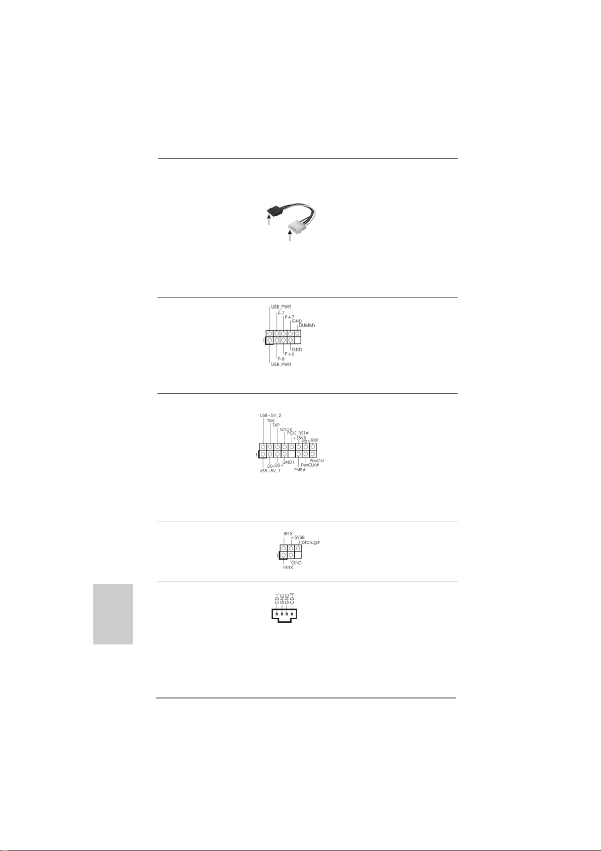
Cordon d’alimentation Veuillez connecter l’extrémité
Série AT A (SA TA) noire du cordon d’alimentation
(en option) SATA sur le conne cteur
connecter au connecteur
d’alimentation du disque
dur SAT A
connecter à l’unité
d’alimentation
électrique
d’alimentation de l’unité.
Connectez ensuite l’extrémité
blanche du cordon d’alimentation
SATA sur le conne cteur
d’alimentation de l’unité
d’alimentation électrique.
En-tête USB 2.0 A côté des six ports USB
(USB6_7 br.9) 2.0 par défaut sur le panneau
(voir p.2 No. 16) E/S, il y a un embases USB
2.0 sur cette carte mère.
Chaque emba se USB 2.0 peut
prendre en charge 2 ports USB
2.0.
En-tête WiFi/E Header Cet en-tête supporte les
(WIFI/E br.15) fonctions WiFi+AP avec le
(voir p.2 No. 20) module ASRock WiFi-802.1 1g
ou WiFi-802.11n, c’est un
ada ptateur de réseau local sa nsfil (WLAN) facile d’utilisation. Il
vous permettra de créer un
environnement sans fil et de
bénéficier des avantages de la
connectivité au réseau sans f il.
F
FF
FF
rançais
rançaisrançais
rançaisrançais
8282
82
8282
Header de Dete ction de Le header supporte la fonction
DeskExpress Hot Plug de detection de HotPlug pour
(IR1 br.5) ASRock DeskExpress.
(voir p.2 fig. 21)
Connecteurs audio internes Ils vous permettent de gérer des
(CD1 br. 4) entrées audio à partir de sources
(CD1: voir p.2 fig. 23) stéréo comme un CD-ROM,
CD1
DVD-ROM, un tuner TV ou une
carte MPEG.
ASRock ALiveNF6P-VSTA Motherboard
Page 83

Connecteur audio panneau C’est une interface pour un câble
av ant audio en façade qui permet le
(HD_AUDIO1 br. 9) branchement et le contrôle
(voir p.2 fig. 24) commodes de périphériques
audio.
1. L’audio à haute définition (HDA) prend en charge la détection de fiche,
mais le fil de panneau sur le châssis doit prendre en charge le HDA pour
fonctionner correctement. Veuillez suivre les instructions dans notre
manuel et le manuel de châssis afin installer votre système.
2. Si vous utilisez le panneau audio AC’97, installez-le sur l’adaptateur audio
du panneau avant conformément à la procédure ci-dessous :
A. Connectez Mic_IN (MIC) à MIC2_L.
B. Connectez Audio_R (RIN) à OUT2_R et Audio_L (LIN) à OUT2_L.
C. Connectez Ground (GND) à Ground (GND).
D. MIC_RET et OUT_RET sont réservés au panneau audio HD. Vous
n’avez pas besoin de les connecter pour le panneau audio AC’97.
E. Entrer dans l’utilitaire de configuration du BIOS. Saisir les Paramètres
avancés puis sélectionner Configuration du jeu de puces. Définir
l’option panneau de commande de [Auto] à [Activé].
F. Entrer dans le système Windows. Cliquer sur l’icône sur la barre de
tâches dans le coin inférieur droite pour entrer dans le Gestionnaire
audio Realtek HD.
Pour Windows® 2000 / XP / XP 64-bit OS:
Cliquer sur « E/S audio», sélectionner « Paramètres du connecteur »
, choisir « Désactiver la détection de la prise du panneau de
commande » et sauvegarder les changements en cliquant sur « OK ».
Pour Windows
Cliquer droit “Fichier” icone , selectionner” la detection
®
VistaTM / VistaTM 64-bit OS:
incapable de jack de panel d’avant “ et sauvegarder le changement par
cliquer”ok”.
Connecteur pour panneau Ce connecteur offre plusieurs
(PANEL1 br. 9) fonctions système en façade.
(voir p.2 fig. 15)
Connecteur du haut-parleur Veuillez connecter le hautdu châssis parleur de châssis sur ce
(SPEAKER1 br. 4) connecteur.
(voir p.2 fig. 10)
ASRock ALiveNF6P-VSTA Motherboard
8383
83
8383
çaisçais
çaisçais
çais
ranran
ranran
ran
FF
FF
F
Page 84

Connecteur pour ventilateur Veuillez connecter le câble du
de châssis ventilateur du châssis sur ce
(CHA_FAN1 br. 3) connecteur en branchant le f il
(voir p.2 fig. 3) noir sur la broche de terre.
Connecteur pour ventilateur Veuillez connecter un câble de
CPU ventilateur d’UC sur ce
(CPU_FAN1 br. 4) connecteur et brancher le fil noir
(voir p.2 fig. 28) sur la broche de terre.
ien que cette carte mère offre un support de (Ventilateur silencieux)
ventilateur de CPU à 4 broches , le ventilateur de CPU à 3 broches peut bien
fonctionner même sans la fonction de commande de vitesse du ventilateur.
Si vous prévoyez de connecter le ventilateur de CPU à 3 broches
au connecteur du ventilateur de CPU sur cette carte
mère, veuillez le connecter aux broches 1-3.
Installation de ventilateur à 3 broches
4
3
2
1
Broches 1-3 connectées
F
FF
FF
rançais
rançaisrançais
rançaisrançais
8484
84
8484
Connecteur d’alimentation A TX Veuillez connecter une unité
(ATXPWR1 br. 24) d’alimentation ATX sur ce
(voir p.2 fig. 27) connecteur.
Bien que cette carte mère fournisse un connecteur de
courant ATX 24 broches, elle peut encore fonctionner si vous
adopter une alimentation traditionnelle ATX 20 broches. Pour
utiliser une alimentation ATX 20 broches, branchez à
l’alimentation électrique ainsi qu’aux broches 1 et 13.
20-Installation de l’alimentation électrique ATX
1
13
12
24
13
24
Connecteur d’alimentation Veuillez noter qu’il est nécessaire
12V A TX de connecter une unité
(ATX12V1 br. 4) d’alimentation électrique avec
(voir p.2 fig. 2) prise A TX 12V sur ce
connecteur afin d’avoir une
alimentation suffisa nte. Faute de
quoi, il ne sera pas possible de
mettre sous tension.
ASRock ALiveNF6P-VSTA Motherboard
1
12
Page 85

Connecteur HDMI_SPDIF Connecteur HDMI_SPDIF,
(HDMI_SPDIF1 3-pin) fournissant une sortie audio
(voir p.2 No. 19) SPDIF vers la carte VGA HDMI,
et permettant au système de
se connecter au un téléviseur
numérique HDMI /un projecteur
/ un périphérique LCD. Veuillez
brancher le connecteur
HDMI_SPDIF de la carte V GA
HDMI sur ce connecteur.
Câble HDMI_SPDIF Veuillez connecter l’extrémité
(en option) noire (A) du câble HDMI_SPDIF
C
B
A
au collecteur HDMI_SPDIF de la
carte-mère. Connectez ensuite
l’extrémité blanche (B ou C) du
câble HDMI_SPDIF au
connecteur HDMI_SPDIF de la
carte VGA HDMI.
A. extrémité noire B. extrémité blanche C. extrémité blanche
(2 briches) (3 briches)
13
24
1
12
çaisçais
çaisçais
çais
ranran
ranran
ran
FF
FF
F
8585
85
8585
ASRock ALiveNF6P-VSTA Motherboard
Page 86
2.72.7
Guide de connexion du collecteur HDMI_SPDIFGuide de connexion du collecteur HDMI_SPDIF
2.7
Guide de connexion du collecteur HDMI_SPDIF
2.72.7
Guide de connexion du collecteur HDMI_SPDIFGuide de connexion du collecteur HDMI_SPDIF
L’interface HDMI (interface multimédia haute définition) est une caractéristique
audio/vidéo entièrement numérique qui offre une interface entre toute source
audio/vidéo numérique compatible, telle qu’un boîtier décodeur, un lecteur DVD, un
récepteur A/V, et un moniteur audio ou vidéo numérique compatible, tel qu’une
télévision numérique (TVN).Un système HDMI complet nécessite une carte VGA
HDMI et une carte-mère compatible HDMI avec collecteur HDMI_SPDIF connecté.
Cette carte-mère est équipée d’un collecteur HDMI_SPDIF qui offre une sortie
audio SPDIF vers la carte VGA HDMI, ce qui permet au système de connecter les
périphériques HDMI TV numérique/projecteur/écran LCD. Pour utiliser la fonction
HDMI sur cette carte-mère, veuillez suivre attentivement les étapes ci-dessous.
Etape 1. Installez la carte VGA HDMI sur la fente PCI Express Graphique de cette
carte-mère. Pour une bonne installation de la carte VGA HDMI, veuillez
vous reporter à la page 77 du guide d’installation.
Etape 2. Connectez l’extrémité noire (A) du câble HDMI_SPDIF au
collecteur HDMI_SPDIF (HDMI_SPDIF1, jaune, voir page 2,
n° 19) de la carte-mère.
Assurez-vous de connecter correctement le câble HDMI_SPDIF à la carte-mère et à la
carte VGA HDMI selon la même définition de broche. Pour la définition de broche du
collecteur HDMI_SPDIF et des connecteurs du câble HDMI_SPDIF, veuillez vous
reporter à la page 85. Pour la définition de broche des connecteurs HDMI_SPDIF,
veuillez vous reporter au manuel de l’utilisateur du fournisseur de la carte VGA
HDMI. Une mauvaise connexion pourrait endommager cette carte-mère et la carte
VGA HDMI de façon permanente.
Etape 3. Connectez l’extrémité blanche (B ou C) du câble HDMI_SPDIF au
connecteur HDMI_SPDIF de la carte V GA HDMI. (Le câble HDMI_SPDIF
comporte deux extrémités blanches (2 broches et 3 broches). Veuillez
choisir l’extrémité blanche appropriée en fonction du connecteur
HDMI_SPDIF de la carte V GA HDMI que vous installez.
F
FF
FF
rançais
rançaisrançais
rançaisrançais
8686
86
8686
extrémité blanche
(2 briches) (B)
Veuillez ne pas connecter l’extrémité blanche du câble HDMI_SPDIF au
mauvais connecteur de la carte VGA HDMI ou de l’autre carte VGA.
Autrement, la carte-mère et la carte VGA pourraient être abîmées. Par
exemple, cetteimage montre le mauvais exemple de connexion du câble
HDMI_SPDIF au connecteur du ventilateur de la carte VGA PCI Express. Veuillez vous
reporter au préalable au manuel de l’utilisateur de la carte VGA pour l’utilisation du
connecteur.
ASRock ALiveNF6P-VSTA Motherboard
extrémité blanche
(3 briches) (C)
Page 87

Etape 4. Connectez le connecteur de sortie HDMI au périphérique HDMI,
tel que la TVHD. Veuillez vous reporter au manuel de l’utilisateur
de la TVHD et vous informer auprès du fournisseur de la carte
VGA HDMI pour obtenir les procédures de connexion détaillées.
Etape 5. Installez les pilotes de la carte VGA HDMI à votre système.
2.82.8
Guide d’installation du disque dur SAGuide d’installation du disque dur SA
2.8
Guide d’installation du disque dur SA
2.82.8
Guide d’installation du disque dur SAGuide d’installation du disque dur SA
Avant d’installer le disque dur SATAII sur votre ordinateur, veuillez lire
attentivement le présent guide d’installation du disque dur SATAII. Certain
paramétrage par défaut des disques durs SATAII ne sont peut-être pas en mode
SATAII pour permettre un fonctionnement avec de meilleures performances. Pour
activer la fonction SATAII, veuillez suivre les instructions ci-dessous avec les
différents vendeurs pour paramétrer correctement votre disque dur SATAII au
mode SATAII avancé sous peine de voir votre disque dur SATAII ne pas
fonctionner en mode SATAII.
Western Digital
Pour activer SATA 1.5 Go/s, raccourcir les broches 5 et 6.
D’autre part, si vous voulez activer SATAII 3.0 Go/s, enlever le cavalier entre la
broche 5 et la broche 6.
TT
T
TT
AIIAII
AII
AIIAII
SAMSUNG
Pour activer SATA 1.5 Go/s, raccourcir les broches 3 et 4.
D’autre part, si vous voulez activer SATAII 3.0 Go/s, enlever le cavalier entre la
broche 3 et la broche 4.
HITACHI
Veuillez utiliser la fonction Outil, outil pouvant être initié sous DOS, pour modifier
les différentes fonctions ATA. Merci de visiter le site HITACHI pour plus de détails.
http://www.hitachigst.com/hdd/support/download.htm
Les exemples donnés précédemment ne vous sont présentés qu’à titre
informatif. Pour les différents produits disques durs SATAIII provenant de
différents vendeurs, les méthodes de mise en place de cavaliers ne sont pas
les mêmes. Veuillez visiter le site Internet des vendeurs pour les mises à
jours.
ASRock ALiveNF6P-VSTA Motherboard
8787
87
8787
çaisçais
çaisçais
çais
ranran
ranran
ran
FF
FF
F
Page 88

2.92.9
Installation des Disques Durs Serial AInstallation des Disques Durs Serial A
2.9
Installation des Disques Durs Serial A
2.92.9
Installation des Disques Durs Serial AInstallation des Disques Durs Serial A
AA
TT
AII (SAAII (SA
A
T
AII (SA
AA
TT
AII (SAAII (SA
Cette carte mère adopte le chipset NVIDIA® GeForce 6150SE / nForce 430 qui prend
en charge les disques durs Serial ATA (SATA) / Serial ATAII (SATAII) et les fonctions
RAID. Vous pouvez in staller les dis que s durs SATA / SATAII sur cette carte mère pour
des appare ils de stockage interne. Cette section vous guidera pour in staller les
disques durs SATA / SATAII.
ETAPE 1 : Installez les disques durs SATA / SATAII dans les baies pour disques de
ETAPE 2 : Connectez le câble d’alimentation SATA au disque dur SATA / SATAII.
ETAPE 3 : Connectez l’une des extrémités du câble de données SATA sur le
ETAPE 4 : Connectez l’autre extrémité du câble de données SATA au disque dur
2.102.10
Fonction “Hot Plug” et “Hot Swap” pour les DisquesFonction “Hot Plug” et “Hot Swap” pour les Disques
2.10
Fonction “Hot Plug” et “Hot Swap” pour les Disques
2.102.10
Fonction “Hot Plug” et “Hot Swap” pour les DisquesFonction “Hot Plug” et “Hot Swap” pour les Disques
Durs SA Durs SA
Durs SA
Durs SA Durs SA
La Carte Mère ALiveNF6P-VSTA supporte la fonction “Hot Plug” pour les péri phériques
SATA / SATAII.
TT
AII)AII)
T
AII)
TT
AII)AII)
votre châssis.
connecteur SATAII de la carte mère.
SATA / SATAII.
TT
A / SAA / SA
TT
T
A / SA
TT
A / SAA / SA
REMARQUE
Qu’est-ce que la fonction « Hot Plug »?
Si les disques durs SATA / SATAII ne sont pas en configuration RAID,
l’action d’insérer et de retirer des disques SATA / SATAII alors que le
système est sous tension et en fonctionnement s’appelle le “Hot Plug”.
T
TT
AIIAII
AII
AIIAII
TT
A (SAA (SA
T
A (SA
TT
A (SAA (SA
TT
A) / SerialA) / Serial
T
A) / Serial
TT
A) / SerialA) / Serial
F
FF
FF
rançais
rançaisrançais
rançaisrançais
8888
88
8888
Qu’est-ce que la fonction « Hot Swap » ?
Si les disques durs sont montés en configuration RAID1 ou RAID5
l’action d’insérer et de retirer des disques SATA / SATAII alors que le
système est sous tension et en fonctionnement s’appelle le “Hot
Swap” .
2.112.11
Guide d’installation des pilotesGuide d’installation des pilotes
2.11
Guide d’installation des pilotes
2.112.11
Guide d’installation des pilotesGuide d’installation des pilotes
Pour installer les pilotes sur votre système, veuillez d’abord insérer le CD dans
votre lecteur optique. Puis, les pilotes compatibles avec votre système peuvent
être détectés automatiquement et sont listés sur la page du pilote du CD. Veuillez
suivre l’ordre de haut en bas sur le côté pour installer les pilotes requis. En
conséquence, les pilotes que vous installez peuvent fonctionner correctement.
ASRock ALiveNF6P-VSTA Motherboard
Page 89
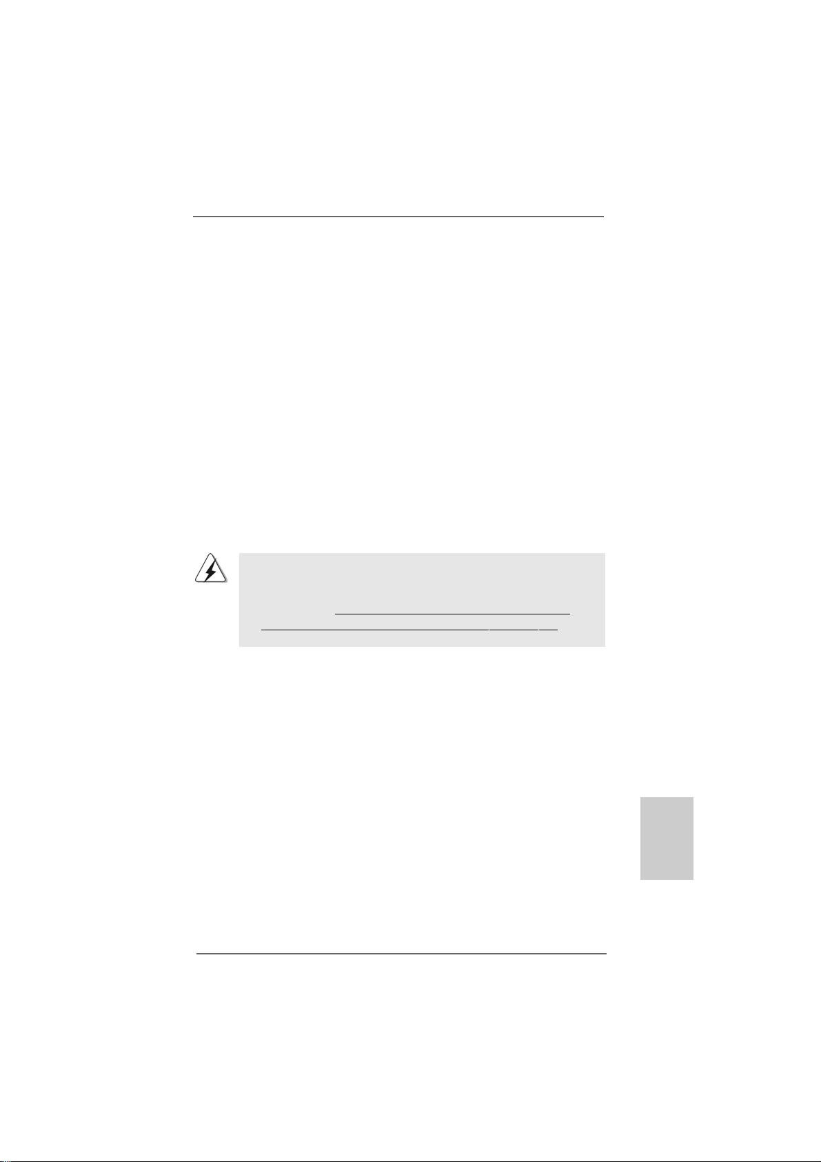
2.122.12
2.12
2.122.12
Si vous voulez simplement installer Windows® 2000, Windows® XP, Windows® XP
64-bit, Windows® VistaTM, Windows® VistaTM 64-bit sur vos disques durs SATA /
SATAII sans fonctions RAID, vous n’avez pas be soin de créer une dis quette pilote
SATA / SATAII. En outre, vous n’avez pas besoin de modifier le s paramètres BIOS.
Vous pouvez la ncer dire ctement l’installation de Windows® 2000, Windows® XP,
Windows® XP 64-bit, Windows® VistaTM, Windows® VistaTM 64-bit directement sur
votre système.
Installation de WindowsInstallation de Windows
Installation de Windows
Installation de WindowsInstallation de Windows
VistaVista
Vista
VistaVista
TMTM
TM
TMTM
/ Vista / Vista
/ Vista
/ Vista / Vista
TMTM
TM
TMTM
64-bit sans fonctions RAID 64-bit sans fonctions RAID
64-bit sans fonctions RAID
64-bit sans fonctions RAID 64-bit sans fonctions RAID
®
2000 / XP / XP 64-bit / 2000 / XP / XP 64-bit /
2000 / XP / XP 64-bit /
2000 / XP / XP 64-bit / 2000 / XP / XP 64-bit /
2.132.13
2.13
2.132.13
Si vous voulez installer l’OS Windows® 2000, Windows® XP, Windows® XP 64-bits,
Windows® VistaTM ou Windows® VistaTM 64-bits sur vos disques durs SATA /
SATAII avec les fonctions RAID, veuillez suivre les procédures ci-dessous, en
fonction de l’OS que vous installez.
2.13.12.13.1
2.13.1
2.13.12.13.1
Si vous voulez installer Windows® 2000, Windows® XP, Windows® XP 64-bit sur
vos disques durs SATA / SATAII avec fonctions RAID, veuillez suivre la procédure
ci-dessous.
ETAP 1: Créez une disquette pilotes SATA / SATAII.
A. Insérez le CD de soutien ASRock dans votre lecteur de disque optique pour
B. Pendant le POST au début du démarrage du système, appuyez sur la touche
C. Lorsque vous voyez s’afficher sur l’écran le message ”Generate Serial ATA
Installation de WindowsInstallation de Windows
Installation de Windows
Installation de WindowsInstallation de Windows
TMTM
TM
TMTM
VistaVista
Vista
VistaVista
Installation de WindowsInstallation de Windows
Installation de Windows
Installation de WindowsInstallation de Windows
fonctions RAIDfonctions RAID
fonctions RAID
fonctions RAIDfonctions RAID
démarrer votre système. (N’insérez AUCUNE dis quette dans le lecteur de dis quette
pour l’instant!)
<F11>, et une fenêtre s’af f iche pour la séle ction de s périphériques de démarrage.
Veuillez sélectionner le CD-ROM comme périphérique de démarrage.
driver diskette [Y/N]?” (Voulez-vous générer une disquette de pilotage Série ATA
[Y/N]?), appuyez sur <Y>.
/ Vista / Vista
/ Vista
/ Vista / Vista
Avant d’installer Windows® 2000 sur votre système, votre disque est
supposé inclure SP4. S’il n’y a aucun SP4 inclut dans votre disque, veuillez
visiter le site Web ci-dessous pour les procédures appropriées pour créer
un disque SP4: http://www.microsoft.com/Windows2000/downloads/
servicepacks/sp4/spdeploy.htm#the_integrated_installation_fmay
TMTM
TM
TMTM
64-bit avec fonctions RAID 64-bit avec fonctions RAID
64-bit avec fonctions RAID
64-bit avec fonctions RAID 64-bit avec fonctions RAID
®
2000 / XP / XP 64-bit / 2000 / XP / XP 64-bit /
2000 / XP / XP 64-bit /
2000 / XP / XP 64-bit / 2000 / XP / XP 64-bit /
®
2000 / XP / XP 64-bit avec 2000 / XP / XP 64-bit avec
2000 / XP / XP 64-bit avec
2000 / XP / XP 64-bit avec 2000 / XP / XP 64-bit avec
çaisçais
çaisçais
çais
ranran
ranran
ran
FF
FF
F
ASRock ALiveNF6P-VSTA Motherboard
8989
89
8989
Page 90

D. Vous voyez alors s’afficher les messages
Please insert a blank
formatted diskette into floppy
drive A:
press any key to start
(Veuillez in sérer une disquette vierge formatée da ns le le cteur de
disquette A : Appuyez sur n’importe quelle touche pour
commencer.)
Veuillez insérer une dis quette dans le lecteur de disquette et appuyez
sur n’importe quelle touche.
E. Le système commencera à formater la disquette et copiera les données des
disques durs SATA / SATAII vers la disquette.
ETAP 2: Conf igurez le BIOS.
A. Entrez dans UTILITAIRE DE CONFIGURA TION BIOS écran Ava ncé
Configuration IDE.
B. Réglez l’option “Mode d’opération SATA” à [RAID].
ETAP 3: Utiliser “RAID Installation Guide” pour définir la configuration
RAID.
Avant de commencer à configurer la f onction RAID, vous devez vérifier le guide
d’installation RAID sur le CD Support, pour une configuration correcte. V euillez vous
référer à la partie Guide d’installation BIOS RAID du document sous le che min suiva nt
du CD Support : .. \ RAID Installation Guide
ETAPE 4: Installer le système d’exploitation Windows® 2000 / Windows
XP / Windows® XP 64-bit sur votre système.
Après avoir mené à bien les étapes 1, 2, 3, vous pouvez in stallerWindows® 2000 /
Windows® XP / Windows® XP 64-bit. Au début de la configuration Windows®,
appuyez sur F6 pour in staller un lecteur RAID tiers. Lorsque vous y êtes invité,
insérez une disquette contena nt le lecteur NVIDIA® RAID. Après lecture de la
disquette, le lecteur est présenté. Sélectionnez le lecteur à installer en fonction du
mode choisi et au système d’exploitation installé.
®
F
FF
FF
rançais
rançaisrançais
rançaisrançais
9090
90
9090
REMARQUE:
Si vous installez les systèmes d’exploitation Windows® 2000, Windows® XP,
Windows® XP 64-bit sur vos disques durs fonctionnant en mode IDE et voulez
gérer (créer, convertir, supprimer, ou reconstruire) les fonctions RAID sur les
disques durs SATA / SATAII, vous avez encore besoin de configurer “Mode
d’opération SATA” à [RAID] tout d’abord. Veuillez ensuite configurer le RAID à
l’aide de la partie Guide d’installation RAID Windows du document sous le
chemin suivant du CD Support:
.. \ RAID Installation Guide
ASRock ALiveNF6P-VSTA Motherboard
Page 91

Vista Vista
Vista
Vista Vista
TMTM
TM
TMTM
/ Vista / Vista
/ Vista
/ Vista / Vista
2.13.22.13.2
2.13.2
2.13.22.13.2
Si vous voulez installer Windows® VistaTM, Windows® VistaTM 64-bit sur vos
disques durs SATA / SATAII avec fonctions RAID, veuillez suivre la procédure cidessous.
ETAP 1: Configurez le BIOS.
A. Entrez dans UTILITAIRE DE CONFIGURATION BIOS écran Avancé
Configuration IDE.
B. Réglez l’option “Mode d’opération SATA” à [RAID].
ETAP 2: Utiliser “RAID Installation Guide” pour définir la configuration
Avant de commencer à configurer la f onction RAID, vous devez vérifier le guide
d’installation RAID sur le CD Support, pour une configuration correcte. Veuillez
vous référer à la partie Guide d’installation BIOS RAID du document sous le chemin
suivant du CD Support : .. \ RAID Installation Guide
ETAPE 3: Installer le système d’exploitation Windows® VistaTM /
Insérez le disque optique de Windows® VistaTM / VistaTM 64-bits dans le lecteur
optique pour démarrer votre système, et suivez les instructions pour installer l’OS
Windows® VistaTM / VistaTM 64-bits sur votre système. Lorsque vous voyez la page
“Où souhaitez-vous installer Windows ?”, veuillez insérer le CD Support d’ ASRock
dans votre lecteur optique, et cliquer sur le bouton “Charger le pilote” en bas à gauche
pour charger les pilotes RAID NVIDIA®. Les pilotes RAID NVIDIA® sont sous le chemin
suivant du CD Support:
.. \ I386 \ Vista (Pour les utilisateurs de Windows® VistaTM)
.. \ AMD64 \ Vista64 (Pour les utilisateurs de Windows® VistaTM 64-bits)
Ensuite, veuillez insérer le disque optique de Windows® VistaTM / VistaTM 64-bits dans
le lecteur optique de nouveau pour continuer l’installation.
Installation de WindowsInstallation de Windows
Installation de Windows
Installation de WindowsInstallation de Windows
fonctions RAIDfonctions RAID
fonctions RAID
fonctions RAIDfonctions RAID
RAID.
Windows® VistaTM 64-bit sur votre système.
®
TMTM
TM
TMTM
64-bit avec 64-bit avec
64-bit avec
64-bit avec 64-bit avec
REMARQUE :
Si vous installez les systèmes d’exploitation Windows® VistaTM / Windows
VistaTM 64-bit sur vos disques durs fonctionnant en mode IDE et voulez
gérer (créer, convertir, supprimer, ou reconstruire) les fonctions RAID sur les
disques durs SATA / SATAII, vous avez encore besoin de configurer “Mode
d’opération SATA” à [RAID] tout d’abord. Veuillez ensuite configurer le RAID à
l’aide de la partie Guide d’installation RAID Windows du document sous le
chemin suivant du CD Support:
.. \ RAID Installation Guide
ASRock ALiveNF6P-VSTA Motherboard
®
9191
91
9191
çaisçais
çaisçais
çais
ranran
ranran
ran
FF
FF
F
Page 92

2.142.14
2.14
2.142.14
Cette carte mère prend en charge la technologie de surcadençage à la volée,
durant le surcadençage, FSB jouit d’une marge meilleure résultant des bus PCI /
PCIE fixés. Avant d’activer la technologie de surcadençage à la volée, veuillez
entrer l’option “Mode de surcadençage” de la configuration du BIOS pour établir la
sélection de [Auto] à [CPU, PCIE, Async.]. Par conséquent, le CPU FSB n’est pas lié
durant le surcadençage, mais les bus PCI et PCIE sont en mode fixé de sorte que
FSB peut opérer sous un environnement de surcadençage plus stable.
3. Informations sur le BIOS3. Informations sur le BIOS
3. Informations sur le BIOS
3. Informations sur le BIOS3. Informations sur le BIOS
La puce Flash Memory sur la carte mère stocke le Setup du BIOS. Lorsque vous
démarrez l’ordinateur, veuillez presser <F2> pendant le POST (Power-On-SelfTest) pour entrer dans le BIOS; sinon, le POST continue ses tests de routine. Si
vous désirez entrer dans le BIOS après le POST, veuillez redémarrer le système
en pressant <Ctl> + <Alt> + <Suppr>, ou en pressant le bouton de reset sur le
boîtier du système. Vous pouvez également redémarrer en éteignant le système et
en le rallumant. L’utilitaire d’installation du BIOS est conçu pour être convivi al. C’es t
un programme piloté par menu, qui vous permet de faire défiler par se s divers sousmenus et de choisir parmi les choix prédéterminés. Pour des informations détaillées
sur le BIOS, veuillez consulter le Guide de l’utilisateur (fichier PDF) dans le CD
technique.
La technologie de surcadençage à la voléeLa technologie de surcadençage à la volée
La technologie de surcadençage à la volée
La technologie de surcadençage à la voléeLa technologie de surcadençage à la volée
Veuillez vous reporter à l’avertissement en page 73 pour connaître les risques
liés à l’overclocking avant d’appliquer la technologie Untied Overclocking.
F
FF
FF
rançais
rançaisrançais
rançaisrançais
9292
92
9292
4. Informations sur le CD de suppor4. Informations sur le CD de suppor
4. Informations sur le CD de suppor
4. Informations sur le CD de suppor4. Informations sur le CD de suppor
Cette carte mère supporte divers systèmes d’exploitation Microsoft® Windows®:
2000 / XP / XP Media Center / XP 64-bit / VistaTM / VistaTM 64-bit. Le CD technique
livré avec cette carte mère contient les pilotes et les utilitaires nécessaires pour
améliorer les f onction s de la carte mère. Pour utiliser le CD technique, insérez-le dans
le lecteur de CD-ROM. Le Menu principal s’affiche automatiquement si “AUTORUN”
est activé da ns votre ordinateur. Si le Menu principal n’a pparaît pa s automatiquement,
localisez dans le CD technique le fichier “ASSETUP.EXE” dans le dossier BIN et
double-cliquez dessus pour afficher les menus.
ASRock ALiveNF6P-VSTA Motherboard
tt
t
tt
Page 93

1. Introduzione
Grazie per aver scelto una scheda madre ASRock ALiveNF6P-VSTA, un a scheda madre
affidabile prodotta secondo i severi criteri di qualità ASRock. Le prestazioni eccellenti e
il design robusto si conformano all’i mpegno di ASRock nella ricerca della qualità e della
resistenza. Questa Guida Rapida all’Installazione contiene l’introduzione alla motherboard
e la guida passo-passo all’installazione. Informazioni più dettagliate sulla motherboard
si possono trovare nel manuale per l’utente presente nel CD di supporto.
Le specifiche della scheda madre e il software del BIOS possono
essere aggiornati, pertanto il contenuto di questo manuale può
subire variazioni senza preavviso. Nel caso in cui questo manuale sia
modificato, la versione aggiornata sarà disponibile sul sito di
ASRock senza altro avviso. Sul sito ASRock si possono anche trovare
le più recenti schede VGA e gli elenchi di CPU supportate.
ASRock website http://www.asrock.com
Se si necessita dell’assistenza tecnica per questa scheda madre,
visitare il nostro sito per informazioni specifiche sul modello che si
sta usando.
www.asrock.com/support/index.asp
1.11.1
Contenuto della confezioneContenuto della confezione
1.1
Contenuto della confezione
1.11.1
Contenuto della confezioneContenuto della confezione
Scheda madre ASRock ALiveNF6P-VSTA
(Micro ATX Form Factor: 9.6-in x 7.7-in, 24.4 cm x 19.6 cm)
Guida di installazione rapida ASRock ALiveNF6P-VSTA
CD di supporto ASRock ALiveNF6P-VSTA
Un cavo IDE 80-pin Ultra ATA 66/100/133
Un cavo per floppy drive a 1,44 Mb
Un cavo dati Serial ATA (SATA) (Opzionale)
Un cavo alimentatore HDD Serial ATA (SATA) (Opzionale)
Un cavo HDMI_SPDIF (Opzionale)
Un “ASRock 6CH Plus” I/O Shield
ASRock ALiveNF6P-VSTA Motherboard
9393
93
9393
ItalianoItaliano
ItalianoItaliano
Italiano
Page 94

Italiano
ItalianoItaliano
ItalianoItaliano
9494
94
9494
1.21.2
SpecificheSpecifiche
1.2
Specifiche
1.21.2
SpecificheSpecifiche
Piattaforma - Micro ATX Form Factor: 9.6-in x 7.7-in, 24.4 cm x 19.6 cm
Processore - Presa AM2 che supporta processore AMD PhenomTM X4 / X2,
Athlon 64FX / 64X2 / X2 / 64 e Sempron
- Pronto AMD LIVE!
- Supporto tecnologia AMD Cool ‘n’ Quiet
- FSB 1000 MHz (2.0 GT/s)
- Supporta la tecnologia overclocking “slegata”
(vedi ATTENZIONE 1)
- Supporta la tecnologia Hyper-Tra nsport
Chipset - NVIDIA® GeForce 6150SE / nForce 430
Memoria - Supporto tecnologia Dual Channel Memory
(vedi ATTENZIONE 2)
- 2 x slot DDRII DIMM
- Supporta DDRII1066/800/667/533 (vedi A TTENZIONE 3)
- Max. 4GB (vedi ATTENZIONE 4)
Booster ibrido - Stepless control per frequenza del processore
(vedi ATTENZIONE 5)
- ASRock U-COP (vedi ATTENZIONE 6)
- Boot Failure Guard (B.F.G.)
- ASRock AM2 Boost: Tecnologia brevettata ASRock per migliorare
le prestazioni della memoria fino al 12,5%
(vedi ATTENZIONE 7)
Slot di - 1 x slot PCI Express x16
espansione - 1 x slot PCI Express x1
- 2 x slot PCI
VGA su scheda - Scheda NVIDIA® GeForce6 – classe grafica integrata
- DX9.0 VGA, Pixel Shader 3.0
- Memoria massima condivisa 256MB
Audio - 5.1 Audio HD CH Windows® VistaTM Premium Level
(ALC662 Audio Codec)
LAN - Realtek PHY RTL8201CL
- Velocità: 10/100 Ethernet
- Supporta Wa ke-On-LAN
Pannello ASRock 6CH I/O Plus
posteriore I/O - 1 x porta PS/2 per mouse
- 1 x porta PS/2 per tastiera
- 1 x Porta COM
- 1 x Porta VGA
- 1 x Porta parallela: supporto ECP/EPP
- 6 x porte USB 2.0 già integrate
ASRock ALiveNF6P-VSTA Motherboard
TM
TM
Page 95

- 1 x Porta RJ-45
- Audio Ja ck: Line In / Line Out / M icrof ono
Connettori - 4 x connettori SAT AII 3.0Go/s, sopporta RAID (RAID 0, RAID 1,
RAID 0+1, RAID 5 e JBOD), NCQ e “Collegamento a caldo”
(vedi ATTENZIONE 8)
- 1 x connettori ATA133 IDE (supporta fino a 2 dispositivi IDE)
- 1 x porta Floppy
- 1 x Intestazione di rilevazione di DeskExpre ss Hot Plug
- 1 x Header HDMI_SPDIF
- Connettore ventolina CPU/telaio
- 24-pin collettore alimentazione ATX
- 4-pin connettore A TX 12V
- Connettori audio interni
- Connettore audio sul pannello frontale
- 1 x Collettore USB 2.0 (supporta 2 porte USB 2.0)
(vedi ATTENZIONE 9)
- 1 x Collettore WiFi/E (vedi A TTENZIONE 10)
BIOS - 4Mb AMI BIOS
- Suppor AMI legal BIOS
- Supporta “Plug and Play”
- Compatibile con ACPI 1.1 wa ke up events
- Supporta jumperfree
- Supporta SMBIOS 2.3.1
CD di - Driver , utilità, software a ntivirus (V ersione dimostrativa)
supporto
Monitor- - Sensore per la temperatura del processore
aggio - Sensore temperatura scheda madre
Hardware - Indicatore di velocità per la ventola del processore
- Indicatore di velocità per la ventola di raffredda mento
- Ventola CPU silenziosa
- Voltaggio: +12V, +5V, +3.3V, Vcore
Compatibi- - Microsoft® Windows® 2000 / XP / Centro multimediale XP / XP 64
lità SO bit / Vista
Certificazioni- FCC, CE, WHQL
TM
/ VistaTM 64 bit
ItalianoItaliano
ItalianoItaliano
Italiano
ASRock ALiveNF6P-VSTA Motherboard
9595
95
9595
Page 96

Italiano
ItalianoItaliano
ItalianoItaliano
9696
96
9696
AVVISO
Si prega di prendere atto che la procedura di overclocking implica dei rischi, come anche
la regolazione delle impostazioni del BIOS, l’applicazione della te cnologia U ntied Overclocking
Technology, oppure l’uso di strumenti di overclocking forniti da terzi. L’overclocking può
influenzare la stabilità del sistema, ed anche provocare danni ai componenti ed alle
periferiche del sistema. La procedura è eseguita a proprio rischio ed a proprie spese. Noi
non possiamo essere ritenuti responsabili per possibili danni provocati dall’overclocking.
ATTENZIONE!
1. Questa scheda madre supporta la tecnologia overclocking “slegata”.
Per i dettagli leggere “Tecnologia di Untied Overclocking” a pagina 115.
2. Questa scheda madre supporta la tecnologia Dual Channel Memory.
Prima di implementare la tecnologia Dual Channel Memory,
assicurarsi di leggere la guida all’installazione dei moduli di memoria,
a pagina 99, per seguire un’installazione appropriata.
3. Il fatto che la velocità della memoria da 1066MHz sia supportata o
meno, dipende dagli AM2+ CPU utilizzati. Dato che la specifica della
DDRII1066 non rientra negli standard di memoria JEDEC, se si
desidera adottare il modulo di memoria DDRII1066 su questa scheda
madre, fare riferimento all’elenco delle memorie supportate nel nostro
sito web per scoprire quali sono i moduli compatibili.
Sito web ASRock
4. A causa delle limitazioni del sistema operativo, le dimensioni effettive
della memoria possono essere inferiori a 4GB per l’accantonamento
riservato all’uso del sistema sotto Windows
Per Windows® XP 64-bit e Windows® VistaTM 64-bit con CPU 64-bit, non
c’è tale limitazione.
5. Anche se questa motherboard offre il controllo stepless, non si
consiglia di effettuare l’overclocking. L’uso di frequenze diverse da
quelle raccomandate per il bus CPU possono provocare l’instabilità
del sistema o danneggiare la CPU.
6. Se il processore si surriscalda, il sistema si chiude automaticamente.
Prima di riavviare il sistema, assicurarsi che la ventolina CPU della
scheda madre funzioni correttamente; scollegare e ricollegare il cavo
d’alimentazione. Per migliorare la dissipazione del calore, ricordare di
applicare l’apposita pasta siliconica tra il processore e il dissipatore
quando si installa il sistema.
7. Questa scheda madre supporta la tecnologia di overclocking ASRock
AM2 Boost. Se si abilita questa funzione nel Setup del BIOS, le
prestazioni della memoria miglioreranno fino al 12,5%, per gli effetti
dipendono sempre dalla CPU AM2 che si adotta. Abilitare questa
funzione provocherà l’overclock della frequenza di case del chipset/
CPU. Tuttavia, non possiamo garantire la stabilità del sistema per tutte
le configurazioni CPU/DRAM. Se il sistema è instabile dopo avere
abilitato la funzione AM2 Boost, significa che la funzione non è adatta al
sistema. Si può scegliere di disabilitare la funzione per mantenere la
stabilità del sistema.
http://www.asrock.com
®
XP e Windows® VistaTM.
ASRock ALiveNF6P-VSTA Motherboard
Page 97

8. Prima di installare il disco rigido SATAII al connettore SATAII, leggere la
“Guida di installazione del disco rigido SATAII” a pagina 110 per
regolare l’unità disco SATAII in modalità SATAII. Si può anche
connettere il disco rigido SATA al connettore SATAII direttamente.
9. La Gestione Risorse per USB 2.0 funziona perfettamente con
Microsoft® Windows® VistaTM 64-bit / VistaTM / XP 64 bit / XP SP1; SP2/
2000 SP4.
10. WiFi/E header supporta la funzione WiFi+AP con il modulo WiFi-802.
11g o WiFi-802.11n ASRock, un adattatore WLAN (rete locale wireless)
semplice da usare. Consente di creare un ambiente wireless e
godersi la comodità di una connettività di rete wireless. Visitate il
nostro sito web per la disponibilità del modulo ASRock WiFi-802.11g o
WiFi-802.11n.
Sito web ASRock http://www.asrock.com
1.31.3
TT
1.3
1.31.3
abella requisiti hardware minimi per Wabella requisiti hardware minimi per W
T
abella requisiti hardware minimi per W
TT
abella requisiti hardware minimi per Wabella requisiti hardware minimi per W
TMTM
TM
Logo VistaLogo Vista
Logo Vista
Logo VistaLogo Vista
Gli integratori di siste ma e gli utenti che acquistano la nostra scheda
madre e desiderano invi are il logo Windows® VistaTM Premium 2007 e
Basic devono osservare la ta bella di seguito sui requisiti hardware mini mi.
CPU Sempron 2800+
Memoria 2 da 512MB canale doppio (Premium)
VG A DX9.0 con driver WDDM
* Se si utilizza la VGA integrata dotata di una memoria totale di 512MB e si desidera
inviare il logo Windows® VistaTM Basic, ridurre le dimensioni di memoria
condivisa della VGA integrata a 64MB. Se si usa una scheda VGA integrata con
dimensioni totali di memoria superiori a 512MB, e si pianifica di sottoporre il logo
Windows® VistaTM Premium o Basic, regolare le dimensioni della memoria
condivisa della scheda VGA integrata su 128MB o più.
* In caso si preveda di utilizzare schede grafiche aggiuntive su questa scheda
madre, consultare i requisiti Premium Discrete su http://www.asrock.com
* Dopo il 1 Giugno 2007, tutti i sistemi Windows® VistaTM vengono richiesti di
essere in accordo ai requisiti minimi del sistema per Windows® VistaTM Premium
2007 logo.
TMTM
Premium 2007 e Basic Premium 2007 e Basic
Premium 2007 e Basic
Premium 2007 e Basic Premium 2007 e Basic
512MB Single Channel (Basic)
2 da 256MB canale doppio (Basic)
indowsindows
indows
indowsindows
®
ItalianoItaliano
ItalianoItaliano
Italiano
ASRock ALiveNF6P-VSTA Motherboard
9797
97
9797
Page 98

2. Installazione
Precauzioni preinstallazionePrecauzioni preinstallazione
Precauzioni preinstallazione
Precauzioni preinstallazionePrecauzioni preinstallazione
Leggere le seguenti precauzioni prima di installare componenti delle
schede madri o di cambiare le impostazioni delle schede madri.
1. Togliere il cavo dalla presa elettrica prima di toccare le componenti. In
caso contrario la schedamadre, le periferiche, e/o i componenti
possono subire gravi danni.
2. Per evitare che l’elettricità statica danneggi la scheda madre, NON
appoggiare la scheda madre su moquette, tappeti o tessuti simili.
Ricordarsi di indossare un braccialetto antistatico collegato a terra o di
toccare un oggetto posizionato a terra prima di maneggiare le
componenti.
3. Tenere i componenti per i bordi e non toccare i ICs.
4. Ogni volta che si disinstalla un componente, appoggiarlo su un
tappetino antistatico messo a terra o depositarlo nella borsa data in
dotazione con il componente.
5. Nell’usare i giraviti per fissare la scheda madre al telaio non serrare
eccessivamente le viti! Altrimenti si rischia di danneggiare la scheda
madre.
2.1 Installazione del processore2.1 Installazione del processore
2.1 Installazione del processore
2.1 Installazione del processore2.1 Installazione del processore
Step 1. Aprire lo zoccolo sollevando la leva da un angolo di 90°.
Step 2. Posizionare la CPU direttamente sopra la presa in modo tale che l’angolo
della CPU con il triangolo dorato corrisponda all’angolo della presa con il
triangolino.
Step 3. Inserire con cautela il processore nello zoccolo finché si adatta
perfettamente.
Italiano
ItalianoItaliano
ItalianoItaliano
9898
98
9898
Il processore ha un solo corretto orientamento. NON forzare il
processore nello zoccolo: i pin potrebbero stortarsi.
Step 4. Quando il processore è posizionato, premere con decisione sullo zoccolo
mentre si abbassa la leva dello zonnettore per fissare il processore.
Quando la leva fa clic sulla linguetta laterale significa che è bloccata.
Step 5. Installare la ventola del processore e l’heatsink. Per una corretta
installazione, per favore fare riferimento ai manuali di istruzione dei
produttori della ventola e dell’heatsink del processore.
ASRock ALiveNF6P-VSTA Motherboard
Page 99

2.2 Installazione dei moduli di memoria (DIMM)2.2 Installazione dei moduli di memoria (DIMM)
2.2 Installazione dei moduli di memoria (DIMM)
2.2 Installazione dei moduli di memoria (DIMM)2.2 Installazione dei moduli di memoria (DIMM)
La motherboard ALiveNF6P-VSTA dispone di due slot DIMM DD RII (Double Data
Rate) a 240 pin e supporta la tecnologia Dual Cha nnel Me mory. Per attivare la
configurazione Dual Cha nnel Memory bisogna in stallare sempre due moduli di
memoria identici (stessa marca, velocità, dimensioni e ti po di chip) negli slot DIMM. In
caso contrario, il sistema funzionerà in modalità single channel.
1. Non è consentito installare la DDR nello slot DDRII, altrimenti si
possono danneggiare questa scheda madre e la DIMM.
2. Se si installa un solo modulo di memoria, oppure due moduli non
identici, non è possibile attivare la tecnologia Dual Channel
Memory.
Installare una DIMMInstallare una DIMM
Installare una DIMM
Installare una DIMMInstallare una DIMM
Scollegare l’alimentazione elettrica prima di aggiungere o
rimuovere i DIMM o altri componenti del sistema.
Step 1. Sbloccare lo slot DIMM premendo i fermi che lo trattengono verso
l’esterno.
Step 2. Allineare una DIMM sullo slot così che il pettine della DIMM combaci con
la sua sede sullo slot.
La DIMM può essere montata correttamente soltanto con un
orientamento. Se si dovesse installare a forza la DIMM nello slot
con un orientamento errato, si causerebbero danni permanenti
alla scheda madre e alla DIMM stessa.
Step 3. Inserire saldamente la DIMM nello slot fino a far scattare completamente
in posizione i fermagli di ritegno alle due estremità e fino ad installare
correttamente la DIMM nella sua sede.
ASRock ALiveNF6P-VSTA Motherboard
9999
99
9999
ItalianoItaliano
ItalianoItaliano
Italiano
Page 100

2.32.3
Slot di espansione (Slot PCI ed Slot PCI Express)Slot di espansione (Slot PCI ed Slot PCI Express)
2.3
Slot di espansione (Slot PCI ed Slot PCI Express)
2.32.3
Slot di espansione (Slot PCI ed Slot PCI Express)Slot di espansione (Slot PCI ed Slot PCI Express)
Sulla scheda madre ALiveNF6P-VSTA c’è 2 slot PCI ed 2 slot PCI Express.
Slot PCI: Sono utilizzati per installare schede di espansione con Interfaccia PCI
a 32-bit.
Slot PCI Express: PCIE1 (slot PCIE x1) usato per schede PCI Express con
schede grafiche di larghezza x1, quali scheda Gigabit LAN,
SATA2, ecc.
PCIE2 (slot PCIE x16) è utilizzato per le schede PCI
Express con schede grafiche a 16 piste.
Installare una scheda di espansioneInstallare una scheda di espansione
Installare una scheda di espansione
Installare una scheda di espansioneInstallare una scheda di espansione
Step 1. Prima d’installare la scheda di espansione, assicurarsi che l’alimentazione
sia stata esclusa oppure che il cavo di alimentazione sia scollegato. Prima
di iniziare l’installazione, si prega di leggere la documentazione della scheda
di espansione e di effettuare le ne cessarie i mpostazioni del hardware.
Step 2. Rimuovere i ganci sullo slot che si intende utilizzare. Tenere a portata di mano
le viti.
Step 3. Allineare il connettore della scheda con lo slot e premere con decisione
finché la scheda è completamente inserita nello slot.
Step 4. Agganciare la scheda allo chassis con le viti.
Italiano
ItalianoItaliano
ItalianoItaliano
100100
100
100100
ASRock ALiveNF6P-VSTA Motherboard
 Loading...