

Page 1
Copyright Notice:Copyright Notice:
Copyright Notice:
Copyright Notice:Copyright Notice:
No part of this installation guide may be reproduced, transcribed, transmitted, or translated in any language, in any form or by any means, except duplication of documentation by the purchaser for backup purpose, without written consent of ASRock Inc.
Products and corporate names appearing in this guide may or may not be registered
trademarks or copyrights of their respective companies, and are used only for identification or explanation and to the owners’ benefit, without intent to infringe.
Disclaimer:Disclaimer:
Disclaimer:
Disclaimer:Disclaimer:
Specifications and information contained in this guide are furnished for informational
use only and subject to change without notice, and should not be constructed as a
commitment by ASRock. ASRock assumes no responsibility for any errors or omissions
that may appear in this guide.
With respect to the contents of this guide, ASRock does not provide warranty of any kind,
either expressed or implied, including but not limited to the implied warranties or
conditions of merchantability or fitness for a particular purpose. In no event shall
ASRock, its directors, officers, employees, or agents be liable for any indirect, special,
incidental, or consequential damages (including damages for loss of profits, loss of
business, loss of data, interruption of business and the like), even if ASRock has been
advised of the possibility of such damages arising from any defect or error in the guide
or product.
This device complies with Part 15 of the FCC Rules. Operation is subject to the
following two conditions:
(1) this device may not cause harmful interference, and
(2) this device must accept any interference received, including interference that
may cause undesired operation.
CALIFORNIA, USA ONLY
The Lithium battery adopted on this motherboard contains Perchlorate, a toxic
substance controlled in Perchlorate Best Management Practices (BMP) regulations
passed by the California Legislature. When you discard the Lithium battery in
California, USA, please follow the related regulations in advance.
“Perchlorate Material-special handling may apply, see
www.dtsc.ca.gov/hazardouswaste/perchlorate”
ASRock Website: http://www.asrock.com
Published February 2007
Copyright©2007 ASRock INC. All rights reserved.
ASRock ALiveNF6G-DVI / ALiveNF6G-VSTA Motherboard
EnglishEnglish
EnglishEnglish
English
11
1
11
Page 2
Motherboard LMotherboard L
Motherboard L
Motherboard LMotherboard L
ayout (ALiveNF6Gayout (ALiveNF6G
ayout (ALiveNF6G
ayout (ALiveNF6Gayout (ALiveNF6G
--
DD
VI)VI)
-
D
VI)
--
DD
VI)VI)
English
EnglishEnglish
EnglishEnglish
22
2
22
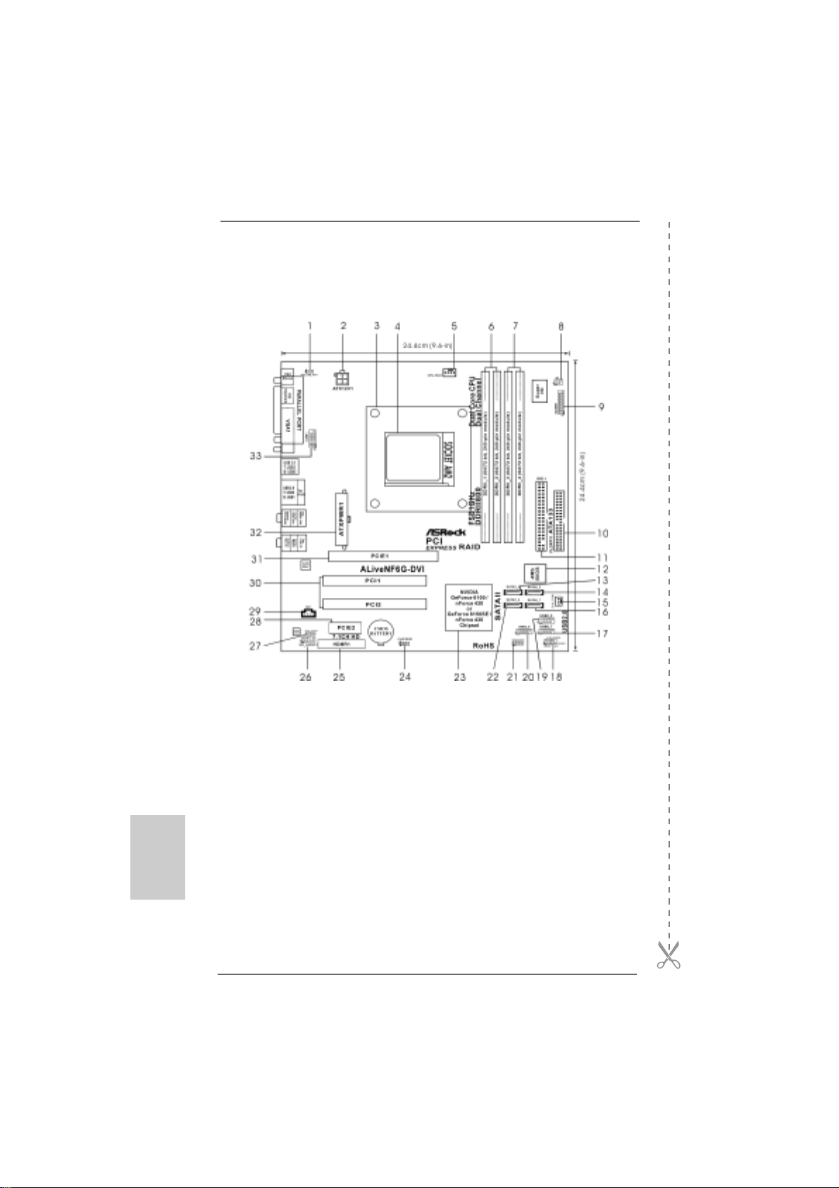
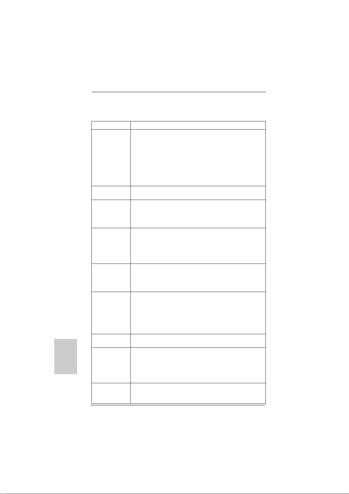
1 PS2_USB_PW1 Jumper 17 USB 2.0 Header (USB6_7, Blue)
2 A TX 12V Power Connector (A TX12V1) 18 System Panel He ader (PANEL1)
3 CPU Heatsink Retention Module 19 USB 2.0 Header (USB8_9, Blue)
4 AM2 940-Pin CPU Socket 20 USB 2.0 Header (USB4_5, Blue)
5 CPU Fan Connector (CPU_FAN1) 21 Chassis Speaker Header (SPEAKER 1)
6 2 x 240-pin DDRII DIMM Slots 22 S e condary SA TAII Conne ctor (SAT AII_2, Red)
(Dual Channel A: DDRII_1, DDRII_2; Yellow) 23 NVIDIA Single Chip
7 2 x 240-pin DDRII DIMM Slots 24 Clear CMOS Jumper (CLRCMOS1)
(Dual Channel B: DDRII_3, DDRII_4; Orange) 2 5 HDMR Slot (HDMR1)
8 Infrared Module Header (IR1) 26 Front Panel Audio Header (HD_AUDIO1)
9 Game Port Header (GAME1) 27 HDMI_SPDIF Header (HDMI_SPDIF1)
10 Floppy Connector (FLOPPY1) 2 8 PCI Express x1 Slot (PCIE2)
11 Primary IDE Connector (IDE1, Blue) 29 Internal Audio Connector: CD1 (Black)
12 Flash Memory 30 PCI Slots (PCI1- 2)
13 Fourth SA TAII Connector (SA T AII_4, Red) 31 PCI Express x16 Slot (PCIE1)
14 Third SA T AII Connector (SAT AII_3, Red) 32 ATX Power Connector (ATXPW R1)
15 Chassis Fan Connector (CHA_FAN1) 3 3 Serial Port Connector (COM1)
16 Primary SA T AII Connector (SA TAII_1, Red)
ASRock ALiveNF6G-DVI / ALiveNF6G-VSTA Motherboard
Page 3
Motherboard LMotherboard L
Motherboard L
Motherboard LMotherboard L
ayout (ALiveNF6Gayout (ALiveNF6G
ayout (ALiveNF6G
ayout (ALiveNF6Gayout (ALiveNF6G
--
VSTVST
-
VST
--
VSTVST
A)A)
A)
A)A)
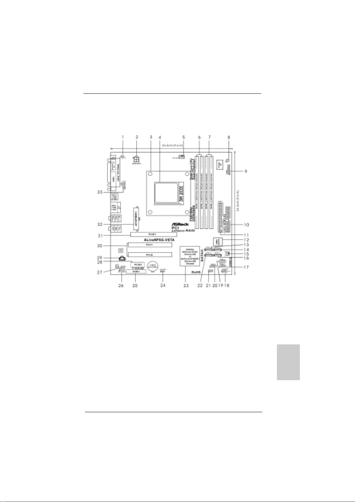
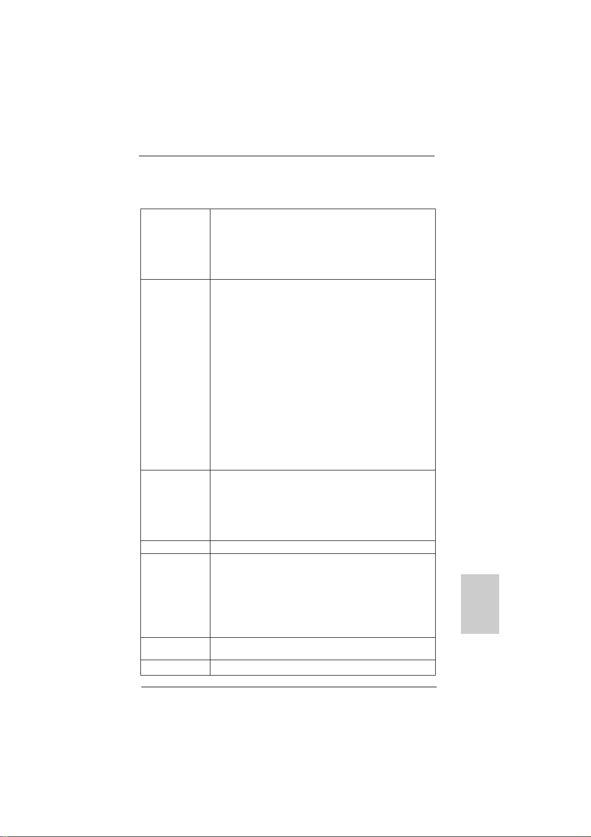
1 PS2_USB_PW1 Jumper 17 USB 2.0 Header (USB6_7, Blue)
2 A TX 12V Power Connector (A TX12V1) 18 Syste m Panel He a der (PANEL1)
3 CPU Heatsink Retention Module 19 USB 2.0 Header (USB8_9, Blue)
4 AM2 940-Pin CPU Socket 20 USB 2.0 Header (USB4_5, Blue)
5 CPU Fan Connector (CPU_FAN1) 21 Chassis Speaker Header (SPEAKER 1)
6 2 x 240-pin DDRII DIMM Slots 22 S e condary SA TAII Connector (SA T AII_2, Red)
(Dual Channel A: DDRII_1, DDRII_2; Yellow) 23 NVIDIA Single Chip
7 2 x 240-pin DDRII DIMM Slots 24 Clear CMOS Jumper (CLRCMOS1)
(Dual Channel B: DDRII_3, DDRII_4; Orange) 2 5 HDMR Slot (HDMR1)
8 Infrared Module Header (IR1) 26 Front Panel Audio Header (HD_AUDIO1)
9 Game Port Header (GAME1) 27 HDMI_SPDIF Header (HDMI_SPDIF1)
10 Floppy Connector (FLOPPY1) 2 8 PCI Express x1 Slot (PCIE2)
11 Primary IDE Connector (IDE1, Blue) 29 Internal Audio Connector: CD1 (Black)
12 Flash Memory 30 PCI Slots (PCI1- 2)
13 Fourth SA TAII Connector (SA T AII_4, Red) 31 PCI Express x16 Slot (PCIE1)
14 Third SA T AII Conne ctor (SA T AII_3, Red) 32 ATX Power Connector (ATXPW R1)
15 Chassis Fan Connector (CHA_FAN1) 3 3 Serial Port Connector (COM1)
16 Primary SATAII Connector (SA T AII_1, Red)
ASRock ALiveNF6G-DVI / ALiveNF6G-VSTA Motherboard
EnglishEnglish
EnglishEnglish
English
33
3
33
Page 4
HD 8CH I/OHD 8CH I/O
HD 8CH I/O
HD 8CH I/OHD 8CH I/O
(ALiveNF6G(ALiveNF6G
(ALiveNF6G
(ALiveNF6G(ALiveNF6G
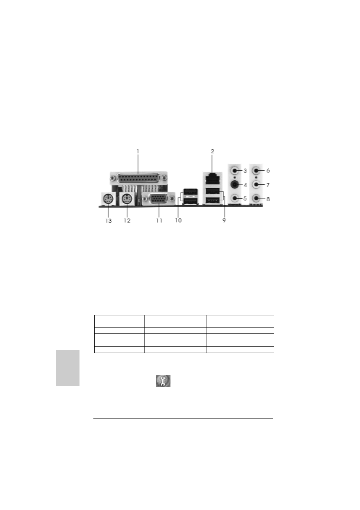
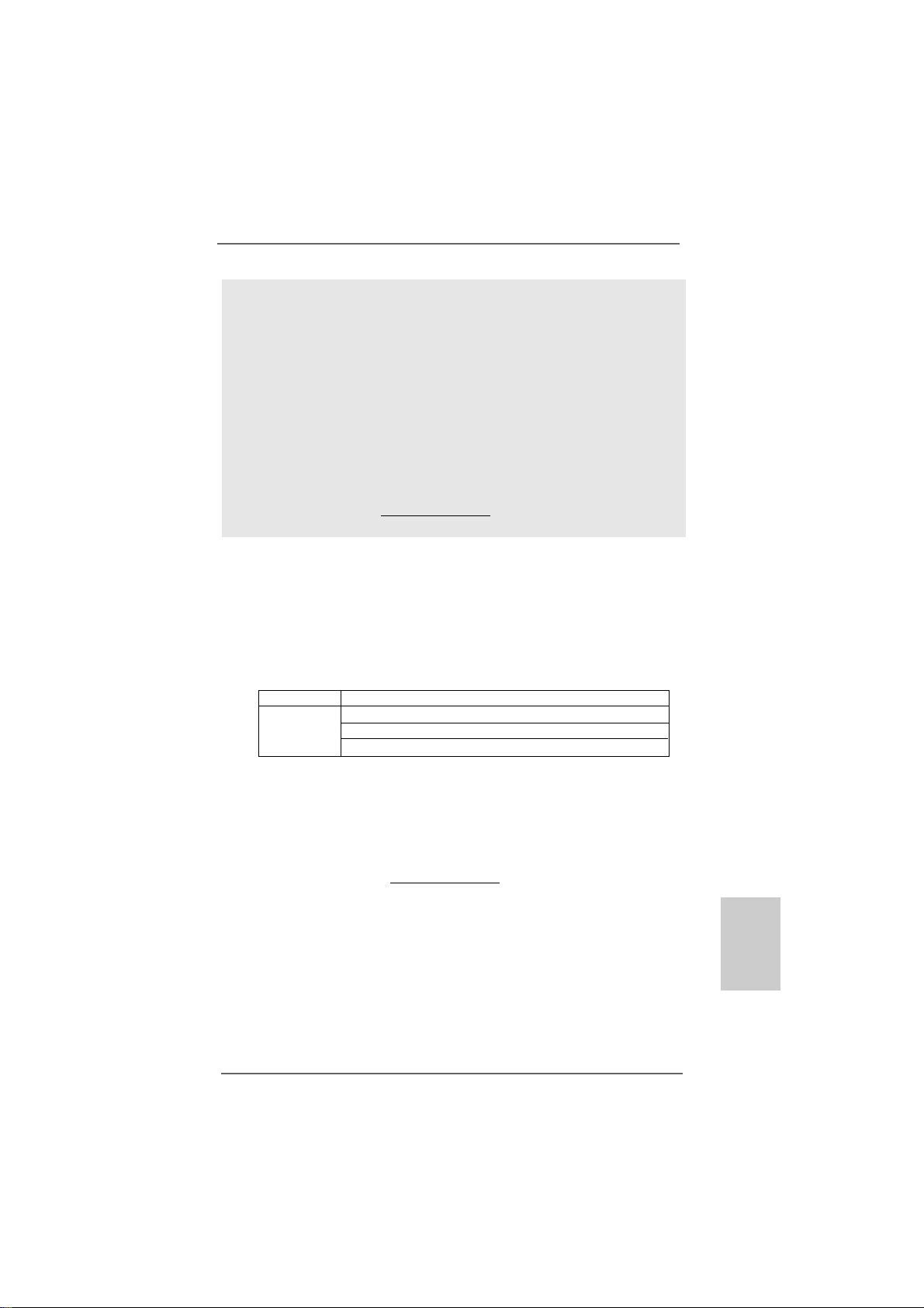
1 Parallel Port 8 Microphone (Pink)
2 RJ-45 Port 9 USB 2.0 Ports (USB01)
3 Side Speaker (Gray) 10 USB 2.0 Ports (USB23)
4 Rear Speaker (Black) 11 VG A Port
5 Central / Bass (Orange) 12 PS/2 Keyboard Port (Purple)
6 Line In (Light Blue) 13 PS/2 Mouse Port (Green)
*7 Front Speaker (Lime)
* If you use 2-channel spea ker, please connect the speaker’s plug into “Front Speaker Jack”. See
the table below for connection details in accordance with the type of speaker you use.
--
DD
VI / ALiveNF6GVI / ALiveNF6G
-
D
VI / ALiveNF6G
--
DD
VI / ALiveNF6GVI / ALiveNF6G
--
VSTVST
-
VST
--
VSTVST
A)A)
A)
A)A)
English
EnglishEnglish
EnglishEnglish
44
4
44
TABLE for Audio Output Connection
Audio Output Channels Front Speaker Rear Speaker Central / Bass Side Speaker
(No. 7) (No. 4) (No. 5) (No. 3)
2 V -- -- -4VV---6 VVV-8 VVVV
* To enable Multi-Streaming function, you need to connect a front panel audio cable to the front
panel audio header. After restarting your computer, you will find “Mixer” tool on your system.
Please select “Mixer ToolBox” , click “Enable playback multi-streaming”, and click
“ok”. Choose “2CH”, “4CH”, “6CH”, or “8CH” and then you are allowed to select “Realtek HDA
Primary output” to use Rear Speaker, Central/Bass, and Front Speaker, or select “Realtek HDA
Audio 2nd output” to use front panel audio.
ASRock ALiveNF6G-DVI / ALiveNF6G-VSTA Motherboard
Page 5
1.1.
IntroductionIntroduction
1.
Introduction
1.1.
IntroductionIntroduction
Thank you for purchasing ASRock ALiveNF6G-DVI / ALiveNF6G-VSTA motherboard,
a reliable motherboard produced under ASRock’s consistently stringent quality control.
It delivers excellent performance with robust design conforming to ASRock’s commitment to quality and endurance.
This Quick Installation Guide contains introduction of the motherboard and step-bystep installation guide. More detailed information of the motherboard can be found in
the user manual presented in the Support CD.
Because the motherboard specifications and the BIOS software might
be updated, the content of this manual will be subject to change without
notice. In case any modifications of this manual occur, the updated
version will be available on ASRock website without further notice. You
may find the latest VGA cards and CPU support lists on ASRock
website as well.
ASRock website http://www.asrock.com
1.11.1
Package ContentsPackage Contents
1.1
Package Contents
1.11.1
Package ContentsPackage Contents
1 x ASRock ALiveNF6G-DVI / ALiveNF6G-VSTA Motherboard
(Micro ATX Form Factor: 9.6-in x 9.6-in, 24.4 cm x 24.4 cm)
1 x ASRock ALiveNF6G-DVI / ALiveNF6G-VSTA Quick Installation Guide
1 x ASRock ALiveNF6G-DVI / ALiveNF6G-VSTA Support CD
1 x Ultra ATA 66/100/133 IDE Ribbon Cable (80-conductor)
1 x 3.5-in Floppy Drive Ribbon Cable
1 x Serial ATA (SATA) Data Cable (Optional)
1 x Serial ATA (SATA) HDD Power Cable (Optional)
1 x HDMI_SPDIF Cable (Optional)
1 x HD 8CH I/O Shield
1 x COM Port Bracket
1 x HDMR Card (Optional)
1 x DVI Graphics-SI Card (only for ALiveNF6G-DVI)
ASRock ALiveNF6G-DVI / ALiveNF6G-VSTA Motherboard
EnglishEnglish
EnglishEnglish
English
55
5
55
Page 6
English
EnglishEnglish
EnglishEnglish
66
6
66
1.21.2
SpecificationsSpecifications
1.2
Specifications
1.21.2
SpecificationsSpecifications
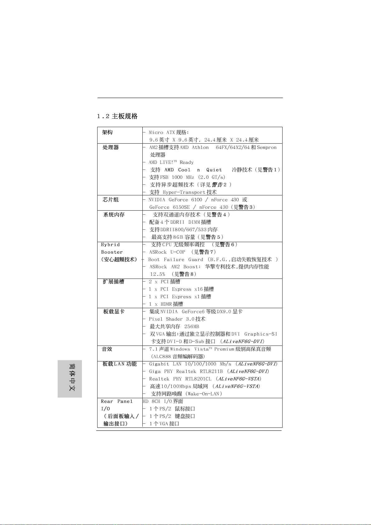
Platform - Micro ATX Form Factor: 9.6-in x 9.6-in, 24.4 cm x 24.4 cm
CPU - Socket AM2 for AMD AthlonTM 64FX / 64X2 / 64 and Sempron
Processors
- AMD LIVE!TM Ready
- Supports AMD’s Cool ‘n’ QuietTM Technology
(see CAUTION 1)
- FSB 1000 MHz (2.0 GT/s)
- Supports Untied Overclocking Technology (see CAUTION 2)
- Supports Hyper-Transport Technology
Chipset - NVIDIA® GeForce 6100 / nForce 430 or
GeForce 6150SE / nForce 430 (see CAUTION 3)
Memory - Dual Channel DDRII Memory T echnology (see CAUTION 4)
- 4 x DDRII DIMM slots
- Support DDRII800/667/533
- Max. capacity: 8GB (see CAUTION 5)
Hybrid Booster - CPU Frequency Stepless Control (see CAUTION 6)
- ASRock U-COP (see CAUTION 7)
- Boot Failure Guard (B.F.G.)
- ASRock AM2 Boost: ASRock Patented Technology to boost
memory performance up to 12.5% (see CAUTION 8)
Expansion Slot - 2 x PCI slots
- 1 x PCI Express x16 slot
- 1 x PCI Express x1 slot
- 1 x HDMR slot
Graphics - Integrated NVIDIA® GeForce6-class graphics D X9.0 V GA
- Pixel Shader 3.0
- Max. shared memory 256MB
- Dual VGA Output: support DVI-D and D-Sub ports with DVI
Graphics-SI card by independent display controllers
(ALiveNF6G-DVI)
Audio - 7.1 CH Windows® VistaTM Premium Level HD Audio
(ALC888 Audio Codec)
LAN - Gigabit LAN 10/100/1000 Mb/s (ALiveNF6G-DVI)
- Giga PHY Realtek RTL8211B (ALiveNF6G-DVI)
- Realtek PHY RTL8201CL (ALiveNF6G-VSTA)
- Speed: 10/100 Ethernet (ALiveNF6G-VSTA)
- Supports Wake-On-LAN
Rear Panel I/O HD 8CH I/O
- 1 x PS/2 Mouse Port
- 1 x PS/2 Keyboard Port
ASRock ALiveNF6G-DVI / ALiveNF6G-VSTA Motherboard
Page 7
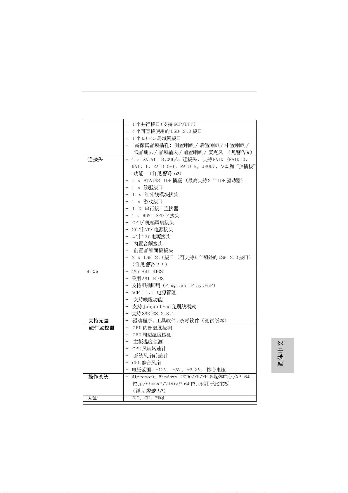
- 1 x VGA Port
- 1 x Parallel Port (ECP/EPP Support)
- 4 x Ready-to-Use USB 2.0 Ports
- 1 x RJ-45 Port
- HD Audio Jack: Side Speaker/Rear Speaker/Central/Bass/
Line in/Front Speaker/Microphone (see CAUTION 9)
Connector - 4 x Serial ATAII 3.0Gb/s connectors, support RAID (RAID 0,
RAID 1, RAID 0+1, RAID 5, JBOD), NCQ, a nd “Hot Plug”
functions (see CAUTION 10)
- 1 x ATA133 IDE connector (supports 2 x IDE devices)
- 1 x Floppy connector
- 1 x IR header
- 1 x Game header
- 1 x COM port header
- 1 x HDMI_SPDIF header
- CPU/Chassis FAN connector
- 20 pin ATX power connector
- 4 pin 12V power connector
- CD in header
- Front panel audio connector
- 3 x USB 2.0 headers (support 6 USB 2.0 ports)
(see CAUTION 11)
BIOS Feature - 4Mb AMI BIOS
- AMI Legal BIOS
- Supports “Plug and Play”
- ACPI 1.1 Compli ance Wake Up Events
- Supports jumperfree
- SMBIOS 2.3.1 Support
Support CD - Drivers, Utilities, AntiVirus Software (Trial Version)
Hardware - CPU Internal Temperature Sensing
Monitor - CPU Ambient Temperature Sensing
- Chassis Temperature Sensing
- CPU Fan Tachometer
- Chassis Fan Tachometer
- CPU Quiet Fan
- Voltage Monitoring: +12V, +5V, +3.3V, Vcore
OS - Microsoft® Windows® 2000/XP/XP Media Center/XP 64-bit/
VistaTM/VistaTM 64-bit compliant (see CAUTION 12)
Certifications - FCC, CE, Microsoft® WHQL Certificated
EnglishEnglish
EnglishEnglish
English
ASRock ALiveNF6G-DVI / ALiveNF6G-VSTA Motherboard
77
7
77
Page 8

English
EnglishEnglish
EnglishEnglish
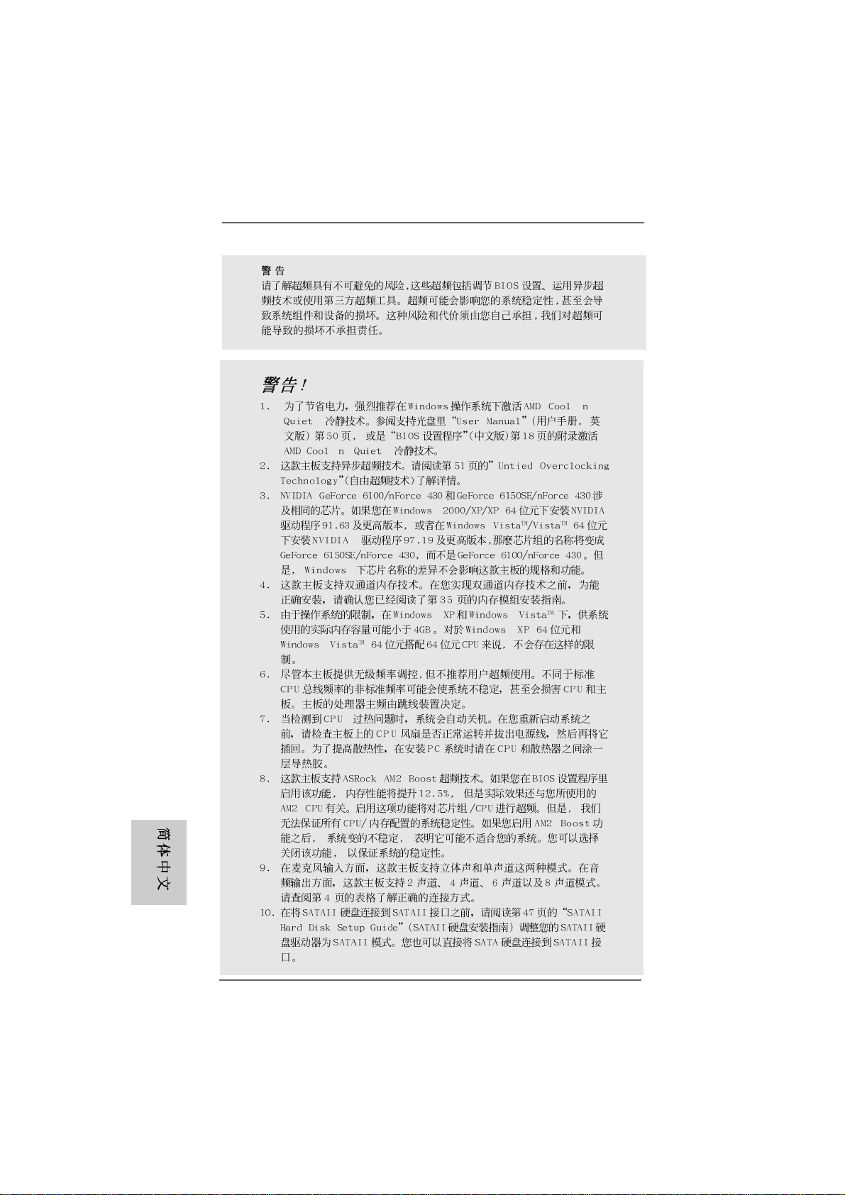
WARNING
Please realize that there is a certain risk involved with overclocking, including adjusting
the setting in the BIOS, applying Untied Overclocking Technology, or using the thirdparty overclocking tools. Overclocking may affect your system stability, or even
cause damage to the components and devices of your system. It should be done at
your own risk and expense. We are not responsible for possible damage caused by
overclocking.
CAUTION!
1. For power-saving’s sake, it is strongly recommended to enable AMD’s Cool ‘n’
QuietTM technology under Windows system. See APPENDIX on page 50 of
“User Manual” in the Support CD to enable AMD’s Cool ‘n’ QuietTM technology.
2. This motherboard supports Untied Overclocking T echnology. Plea se read “Untied Overclocking Technology” on page 27 for details.
3. Both NVIDIA® GeForce 6100 / nForce 430 a nd GeForce 6150SE / nForce 430
refer to the same chipset. If you install NVIDIA® driver with 91.63 version or
above under Windows® 2000 / XP / XP 64-bit, or install NVIDIA® driver with
97.19 version or above under Windows® VistaTM / VistaTM 64-bit, the chipset
name will be GeForce 6150SE / nForce 430 instead of GeForce 6100 / nForce
430. However, the difference in device name under Windows® does not affect
any specification and feature of this motherboard.
4. This motherboard supports Dual Channel Memory Technology . Before you
implement Dual Channel Memory Technology, make sure to read the
installation guide of memory modules on page 11 for proper installation.
5. Due to the operating system limitation, the actual memory size may be
less than 4GB for the reservation for system usage under Windows
and Windows® VistaTM. For Windows® XP 64-bit and Windows® VistaTM 64bit with 64-bit CPU, there is no such limitation.
6. Although this motherboard offers stepless control, it is not recommended to
perform over-clocking. Frequencies other than the recommended CPU bus
frequencies may cause the instability of the system or damage the CPU.
7. While CPU overheat is detected, the system will automatically shutdown.
Before you resume the system, plea se check if the CPU fa n on the motherboard
functions properly and unplug the power cord, then plug it back again. To
improve heat dissipation, remember to spray thermal grease between the
CPU and the heatsink when you install the PC system.
8. This motherboard supports ASRock AM2 Boost overclocking technology. If
you enable this function in the BIOS setup, the memory performance will
improve up to 12.5%, but the effect still depends on the AM2 CPU you adopt.
Enabling this function will overclock the chipset/CPU reference clock. However,
we can not guarantee the system stability for all CPU/DRAM configurations.
If your system is unstable after AM2 Boost function is enabled, it may not be
applicative to your system. You may choose to disable this function for
keeping the stability of your system.
®
XP
88
8
88
ASRock ALiveNF6G-DVI / ALiveNF6G-VSTA Motherboard
Page 9
9. For microphone input, this motherboard supports both stereo and mono modes.
For audio output, this motherboard supports 2-channel, 4-channel, 6-channel,
and 8-channel mode s. Please check the table on page 4 f or proper connection.
10. Before installing SA TAII hard disk to SATAII conne ctor, plea se re a d the “SAT AII
Hard Disk Setup Guide” on page 23 to adjust your SATAII hard disk drive to
SATAII mode. You can also connect SATA hard disk to SATAII connector
directly.
11. Power Management for USB 2.0 works fine under Microsoft® Windows
VistaTM 64-bit / VistaTM / XP 64-bit / XP SP1 or SP2 / 2000 SP4.
12. Microsoft® Windows® VistaTM / VistaTM 64-bit driver keeps on updating now. As
long as we have the latest driver, we will update it to our website in the future.
Please visit our website for Microsoft® Windows® VistaTM / VistaTM 64-bit driver
and related information.
ASRock website http://www.asrock.com
1.31.3
Minimum Hardware RMinimum Hardware R
1.3
Minimum Hardware R
1.31.3
Minimum Hardware RMinimum Hardware R
TMTM
TM
TMTM
VistaVista
Vista
VistaVista
For system integrators and users who purchase this motherboard and
plan to submit Windows® VistaTM Premium and Basic logo, please follow the
below table for minimum hardware requirement.
CPU Sempron 2800+
Memory 512MB x 2 Dual Channel (Premium)
Premium and Basic Logo Premium and Basic Logo
Premium and Basic Logo
Premium and Basic Logo Premium and Basic Logo
512MB Single Channel (Ba sic)
256MB x 2 Dual Channel (Basic)
equirement Tequirement T
equirement T
equirement Tequirement T
able for Wable for W
able for W
able for Wable for W
®
indowsindows
indows
indowsindows
®®
®
®®
* If you use onboard VGA with total system memory size 512MB and plan to
submit Windows® VistaTM Basic logo, please adjust the shared memory size of onboard
VGA to 64MB. If you use onboard VGA with total system memory size above 512MB
and plan to submit Windows® VistaTM Premium or Basic logo, please adjust the shared
memory size of onboard VGA to 128MB or above.
* If you plan to use external graphics card on this motherboard, please refer to Pre mium
Discrete requirement at http://www.asrock.com
ASRock ALiveNF6G-DVI / ALiveNF6G-VSTA Motherboard
EnglishEnglish
EnglishEnglish
English
99
9
99
Page 10
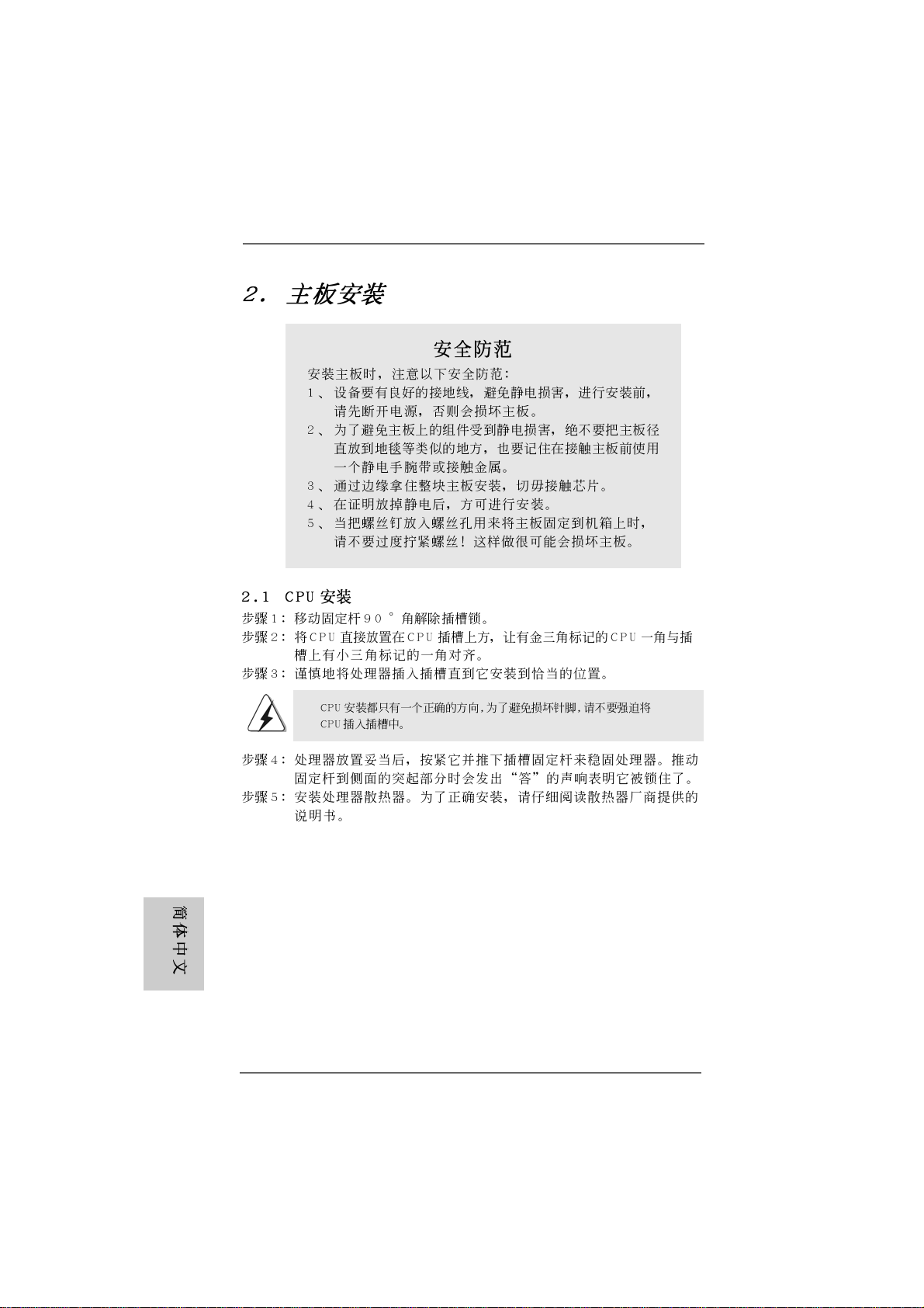
2.2.
InstallationInstallation
2.
Installation
2.2.
InstallationInstallation
Pre-installation PrecautionsPre-installation Precautions
Pre-installation Precautions
Pre-installation PrecautionsPre-installation Precautions
Take note of the following precautions before you install motherboard components or change any motherboard settings.
1. Unplug the power cord from the wall socket before touching any
component. Failure to do so may cause severe damage to the
motherboard, peripherals, and/or components.
2. To avoid damaging the motherboard components due to static
electricity, NEVER place your motherboard directly on the carpet or the like. Also remember to use a grounded wrist strap or
touch a safety grounded object before you handle components.
3. Hold components by the edges and do not touch the ICs.
4. Whenever you uninstall any component, place it on a
grounded antstatic pad or in the bag that comes with the
component.
5. When placing screws into the screw holes to secure the
motherboard to the chassis, plea se do not over-tighten the screws!
Doing so may damage the motherboard.
2.12.1
CPU InstallationCPU Installation
2.1
CPU Installation
2.12.1
CPU InstallationCPU Installation
Step 1. Unlock the socket by lifting the lever up to a 90° angle.
Step 2. Position the CPU directly above the socket such that the CPU corner with
the golden triangle matches the socket corner with a small triangle.
Step 3. Carefully insert the CPU into the socket until it fits in place.
English
EnglishEnglish
EnglishEnglish
1010
10
1010
The CPU fits only in one correct orientation. DO NOT force the CPU
into the socket to avoid bending of the pins.
Step 4. When the CPU is in place, press it firmly on the socket while you push
down the socket lever to secure the CPU. The lever clicks on the side tab
to indicate that it is locked.
Step 5. Install CPU fan and heatsink. For proper installation, please kindly refer to
the instruction manuals of your CPU fan and heatsink vendors.
ASRock ALiveNF6G-DVI / ALiveNF6G-VSTA Motherboard
Page 11
2.2 Installation of Memory Modules (DIMM)2.2 Installation of Memory Modules (DIMM)
2.2 Installation of Memory Modules (DIMM)
2.2 Installation of Memory Modules (DIMM)2.2 Installation of Memory Modules (DIMM)
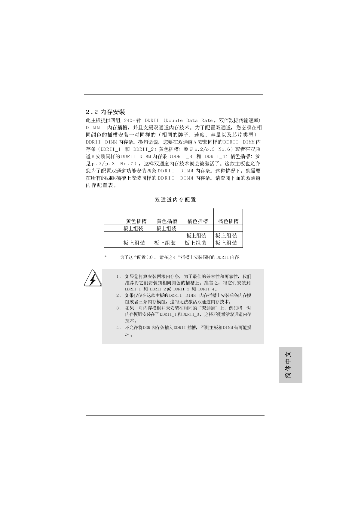
This motherboard provides four 240-pin DD RII (Double Data Rate II) DIMM slots,
and supports Dual Channel Memory Technology . For dual channel configuration,
you always need to install identical (the same brand, speed, size and chiptype) DDRII DIMM pair in the slots of the same color. In other words, you have to
install identical DDRII DIMM pair in Dual Channel A (DDRII_1 and DDRII_2;
Y ellow slots; see p.2/p.3 No.6) or identical DDRII DIMM pair in Dual Channel B
(DDRII_3 and DDRII_4; Orange slots; see p.2/p.3 No.7), so that Dual Channel
Memory Technology can be activated. This motherboard also allows you to
install four DDRII DIMMs for dual channel configuration, and please install iden-
tical DDRII DIMMs in all four slots. You may refer to the Dual Channel Memory
Configuration Table below.
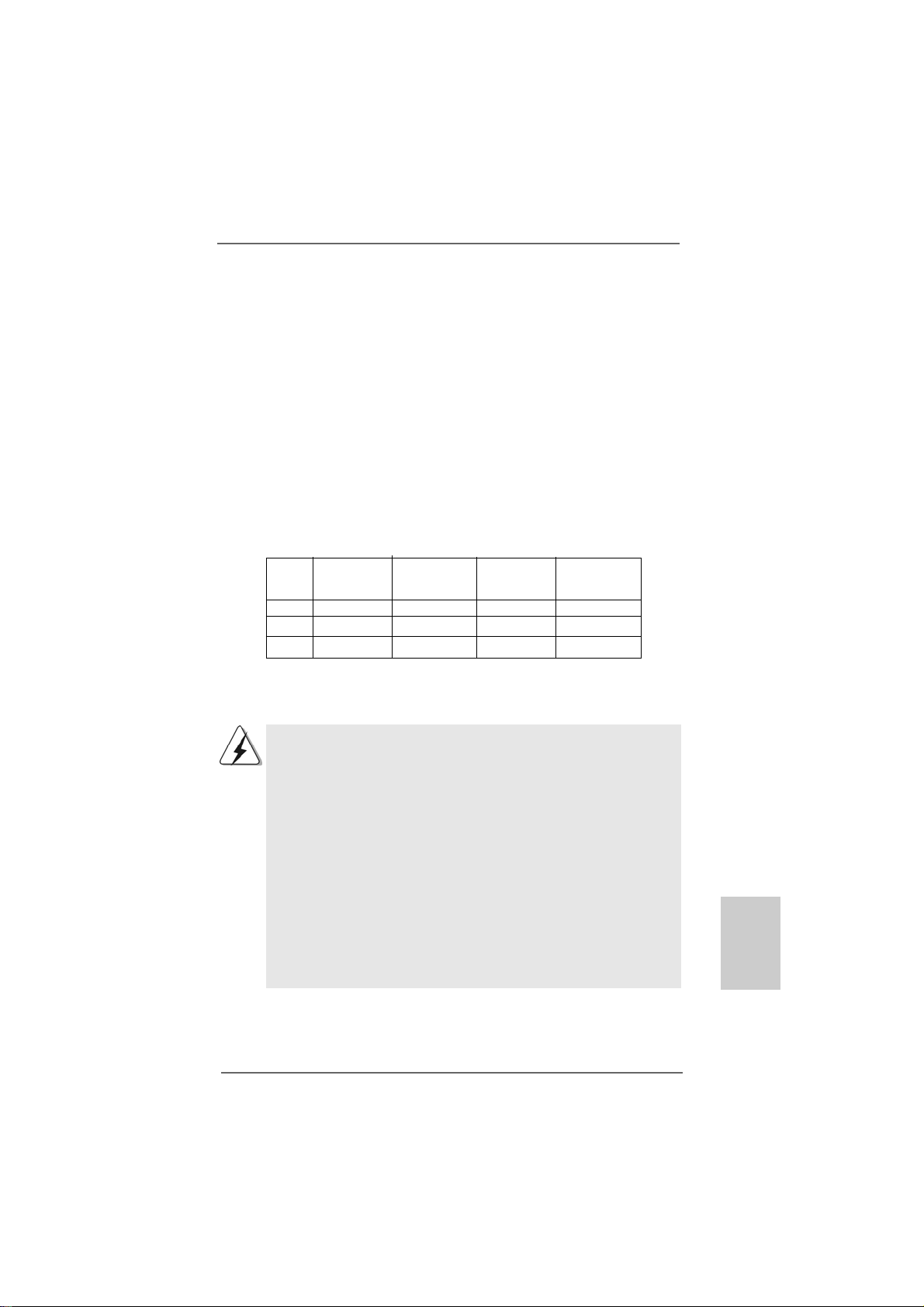
Dual Channel Memory Configurations
DDRII_1 DDRII_2 DDRII_3 DDRII_4
(Yellow Slot) (Yellow Slot) (Orange Slot) (Orange Slot)
(1) Populated Populated - (2) - - Populated Populated
(3)* Populated Populated Populated Populated
* For the configuration (3), please install identical DDRII DIMMs in all f our slots.
1. If you want to install two memory modules, for optimal compatibility
and reliability, it is recommended to install them in the slots of the
same color. In other words, install them either in the set of yellow
slots (DDRII_1 and DDRII_2), or in the set of orange slots (DDRII_3
and DDRII_4).
2. If only one memory module or three memory modules are installed
in the DDRII DIMM slots on this motherboard, it is unable to activate
the Dual Channel Memory T e chnology.
3. If a pair of memory modules is NOT installed in the same Dual
Channel, for exa mple, in stalling a pair of memory module s in DD RII_1
and DDRII_3, it is unable to activate the Dual Channel Memory
Technology .
4. It is not allowed to install a DDR memory module into DDRII slot;
otherwise, this motherboard and DIMM may be damaged.
ASRock ALiveNF6G-DVI / ALiveNF6G-VSTA Motherboard
1111
11
1111
EnglishEnglish
EnglishEnglish
English
Page 12
Installing a DIMMInstalling a DIMM
Installing a DIMM
Installing a DIMMInstalling a DIMM
Please make sure to disconnect power supply before adding or
removing DIMMs or the system components.
Step 1. Unlock a DIMM slot by pressing the retaining clips outward.
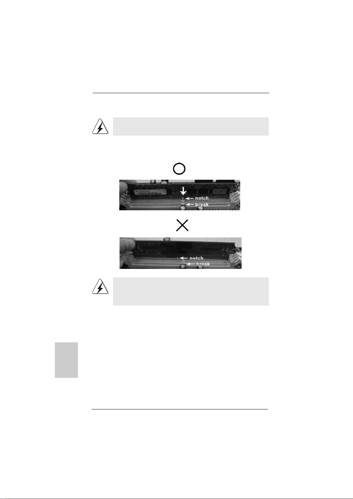
Step 2. Align a DIMM on the slot such that the notch on the DIMM matches the break
on the slot.
English
EnglishEnglish
EnglishEnglish
1212
12
1212
The DIMM only fits in one correct orientation. It will cause permanent
damage to the motherboard and the DIMM if you force the DIMM into the
slot at incorrect orientation.
Step 3. Firmly insert the DIMM into the slot until the retaining clips at both ends fully
snap back in place and the DIMM is properly seated.
ASRock ALiveNF6G-DVI / ALiveNF6G-VSTA Motherboard
Page 13
2.3 Expansion Slots (PCI, HDMR and PCI Express Slots)2.3 Expansion Slots (PCI, HDMR and PCI Express Slots)
2.3 Expansion Slots (PCI, HDMR and PCI Express Slots)
2.3 Expansion Slots (PCI, HDMR and PCI Express Slots)2.3 Expansion Slots (PCI, HDMR and PCI Express Slots)
There are 2 PCI slots, 1 HDMR slot and 2 PCI Express slots on this motherboard.
PCI slots: PCI slots are used to install expansion cards that have the 32-bit PCI
interface.
HDMR slot: HDMR slot is used to insert a HDMR card (optional) with v.92 Modem
functionality. The HDMR slot is shared with PCIE2 slot; you
can only choose either PCIE2 slot or HDMR slot to use.
PCIE Slots: PCIE1 (PCIE x16 slot) is used for PCI Express cards with x16 lane
width graphics cards or ASRock DVI Graphics-SI card (ALiveNF6G-
DVI).
PCIE2 (PCIE x1 slot) is used for PCI Express cards with x1 lane
width cards, such as Gigabit LAN card, SATA2 card, etc.
You can only choose either PCI Express VGA card or DVI Graphics-SI
card to install to PCIE1 (PCIE x16 slot) on ALiveNF6G-DVI motherboard.
Installing an expansion cardInstalling an expansion card
Installing an expansion card
Installing an expansion cardInstalling an expansion card
Step 1. Before installing the expansion card, please make sure that the power
supply is switched off or the power cord is unplugged. Please read the
documentation of the expansion card and make necessary hardware
settings for the card before you start the installation.
Step 2. Remove the bracket facing the slot that you intend to use. Keep the screws
for later use.
Step 3. Align the card connector with the slot and press firmly until the card is
completely seated on the slot.
Step 4. Fasten the card to the chassis with screws.
ASRock ALiveNF6G-DVI / ALiveNF6G-VSTA Motherboard
1313
13
1313
EnglishEnglish
EnglishEnglish
English
Page 14
2.4 Easy Dual Monitor Feature (ALiveNF6G-DVI)2.4 Easy Dual Monitor Feature (ALiveNF6G-DVI)
2.4 Easy Dual Monitor Feature (ALiveNF6G-DVI)
2.4 Easy Dual Monitor Feature (ALiveNF6G-DVI)2.4 Easy Dual Monitor Feature (ALiveNF6G-DVI)
This motherboard supports Dual Monitor feature. With the onboard VGA/D-Sub output
and the external installation of our DVI Graphics-SI card, this motherboard provides
users with dual VGA output support: DVI-D and D-Sub ports. You can easily enjoy the
benefits of dual VGA output support by connecting the D-Sub input monitor to the
VGA/D-Sub port on the I/O panel and connecting the DVI-D input monitor to our DVI
Graphics-SI card inserted to PCIE1 (PCIE x16 slot) on this motherboard. Be sides, this
motherboard provides independent display controllers for DVI-D and D-Sub ports to
support dual VGA output so that DVI-D and D-sub ports can drive same or different
display contents. To enjoy Dual Monitor feature, please refer to the below procedures
for proper installation of DVI Graphics-SI card in advance.
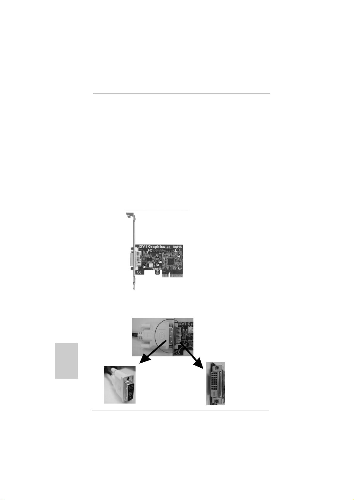
Step 1. Install the D VI Graphics-SI card to PCIE1 (PCIE x16 slot). Plea se refer to the
expansion card installation procedures on page 13 for details.
DVI Graphics-SI card
English
EnglishEnglish
EnglishEnglish
1414
14
1414
Step 2. Connect the DVI-D connector of DVI-D input monitor to the DVI-D output
connector of DVI Graphics-SI card which is inserted to PCIE1 (PCIE x16
slot) on this motherboard.
DVI-D output connec-
DVI-D connector of
DVI-D input monitor
ASRock ALiveNF6G-DVI / ALiveNF6G-VSTA Motherboard
tor of DVI Graphics-SI
card
Page 15
Step 3. Connect the D-Sub input monitor cable to the VGA/D-Sub port on the I/O
panel of this motherboard.
Step 4. I f you have installed NVIDIA
system already, you can freely enjoy the benefits of DVI-D output function
with this motherboard after your system boots. If you haven’t installed
NVIDIA® VGA driver yet, please install NVIDIA® VGA driver from our support
CD to your system and restart your computer. Then you can start to use
DVI-D output function with this motherboard.
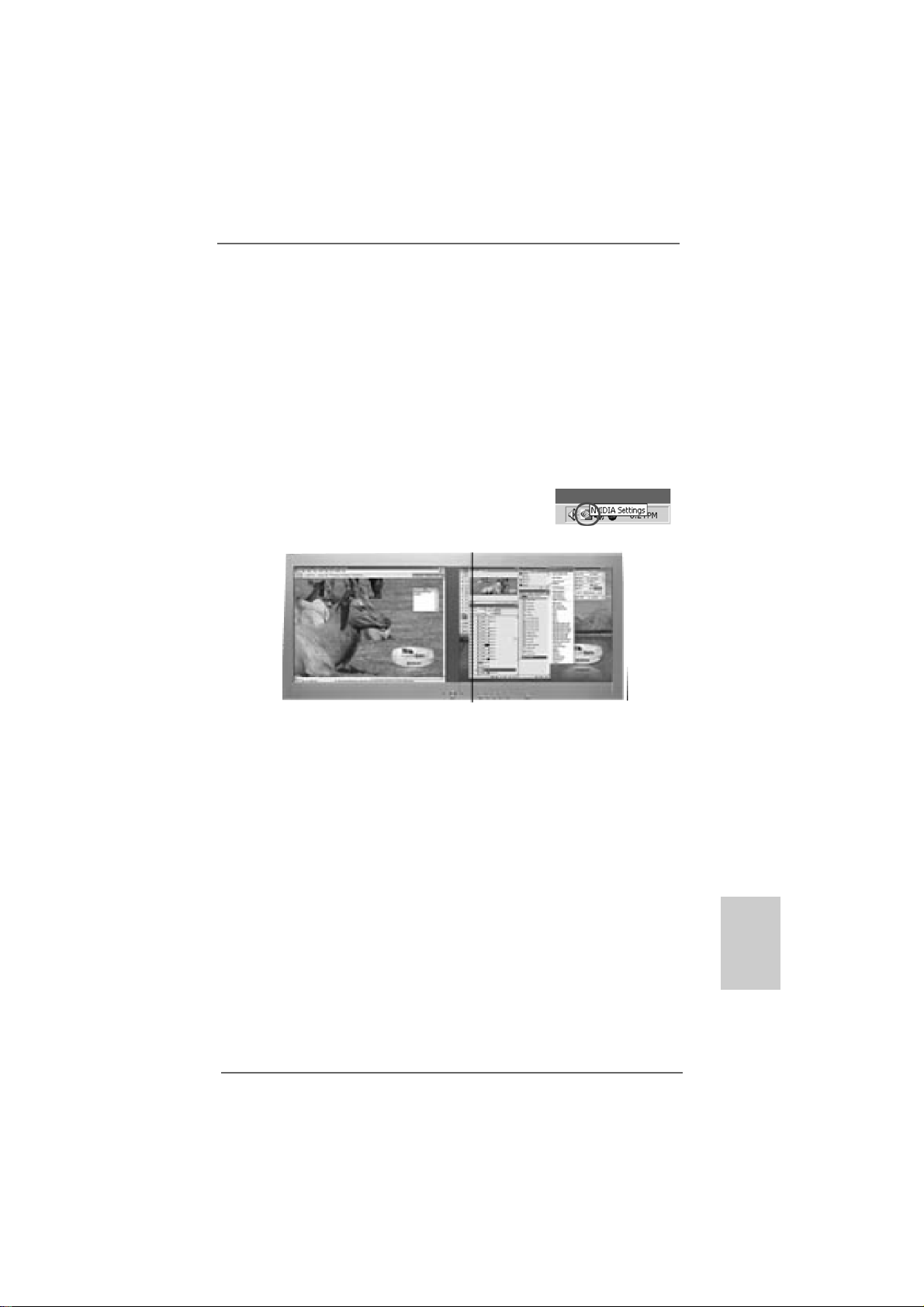
Step 5. Righ click the “NVIDIA Settings” icon on on the desktop to adjust the display
mode you plan to use by following the instructions shown on the “NVIDIA
Settings” screen. You are allowed to choose same or different display
contents shown on the two monitors you install.
Independent display controllers for DVI-D and D-Sub ports
to support dual VGA output: DVI-D and D-sub ports can
drive same or different display contents
®
VGA driver from our support CD to your
ASRock ALiveNF6G-DVI / ALiveNF6G-VSTA Motherboard
1515
15
1515
EnglishEnglish
EnglishEnglish
English
Page 16

English
EnglishEnglish
EnglishEnglish
2.5 Easy Multi Monitor Feature2.5 Easy Multi Monitor Feature
2.5 Easy Multi Monitor Feature
2.5 Easy Multi Monitor Feature2.5 Easy Multi Monitor Feature
(ALiveNF6G (ALiveNF6G
(ALiveNF6G
(ALiveNF6G (ALiveNF6G
This motherboard supports Multi Monitor upgrade. With the internal onboard VGA
and the external add-on PCI Express VGA card, you can easily enjoy the benefits
of Multi Monitor feature. Please refer to the following steps to set up a multi
monitor environment:
1. Install the NVIDIA® PCI Express V GA card to PCIE1 (PCIE x16 slot). Please refer
to page 13 for proper expansion card installation procedures for details.
2. Connect the D-Sub input monitor cable to the VGA/D-Sub port on the I/O panel
of this motherboard. Connect another D-Sub input monitor cable to the
VGA/D-Sub connector of the add-on PCI Express VGA card. Connect the DVI-D
input monitor cable to the VGA/DVI-D connector of the add-on PCI Express VGA
card.
3. Boot your system. Press <F2> to enter BIOS setup. Enter “Share Memory”
option to adjust the memory capability to [16MB], [32MB], [64MB], [128MB], or
[256MB] to enable the function of onboard VGA/D-sub. Please make sure that
the value you select is less than the total capability of the system memory. If
you do not adjust the BIOS setup, the default value of “Share Memory”, [Auto],
will disable onboard VGA/D-Sub function when the add-on VGA card is
inserted to this motherboard.
4. Install the onboard VGA driver to your system. If you have installed the
onboard VGA driver already, there is no need to install it again.
5. Set up a multi-monitor display. Right click the desktop, choose “Properties”, and
select the “Settings” tab so that you can adjust the parameters of the multi monitor according to the steps below. (The item names and operation
procedures described in this step are under Windows® XP environment. If you
install other Windows® OS, the item names and operation procedures may be
similar.)
A. Click the “Identify” button to display a large number on each monitor.
B. Right-click the display icon in the Display Properties dialog that you wish to
be your primary monitor, and then select “Primary”. When you use multiple
monitors with your card, one monitor will always be Primary, and all
additional monitors will be designated as Secondary.
C. Select the display icon identified by the number 2.
D. Click “Extend my Windows desktop onto this monitor”.
E. Right-click the display icon and select “Attached”, if necessary.
F. Set the “Screen Resolution” and “Color Quality” as appropriate for the
second monitor. Click “Apply” or “OK” to apply these new values.
G. Repeat steps C through E for the diaplay icon identified by the number one,
two, and three.
-D-D
VI / ALiveNF6GVI / ALiveNF6G
-D
VI / ALiveNF6G
-D-D
VI / ALiveNF6GVI / ALiveNF6G
--
VSTVST
-
VST
--
VSTVST
A)A)
A)
A)A)
1616
16
1616
ASRock ALiveNF6G-DVI / ALiveNF6G-VSTA Motherboard
Page 17
6. Use Multi Monitor feature. Click and drag the display icons to positions
representing the physical setup of your monitors that you would like to use. The
placement of display icons determines how you move items from one monitor to
another.
2.62.6
Jumpers SetupJumpers Setup
2.6
Jumpers Setup
2.62.6
Jumpers SetupJumpers Setup
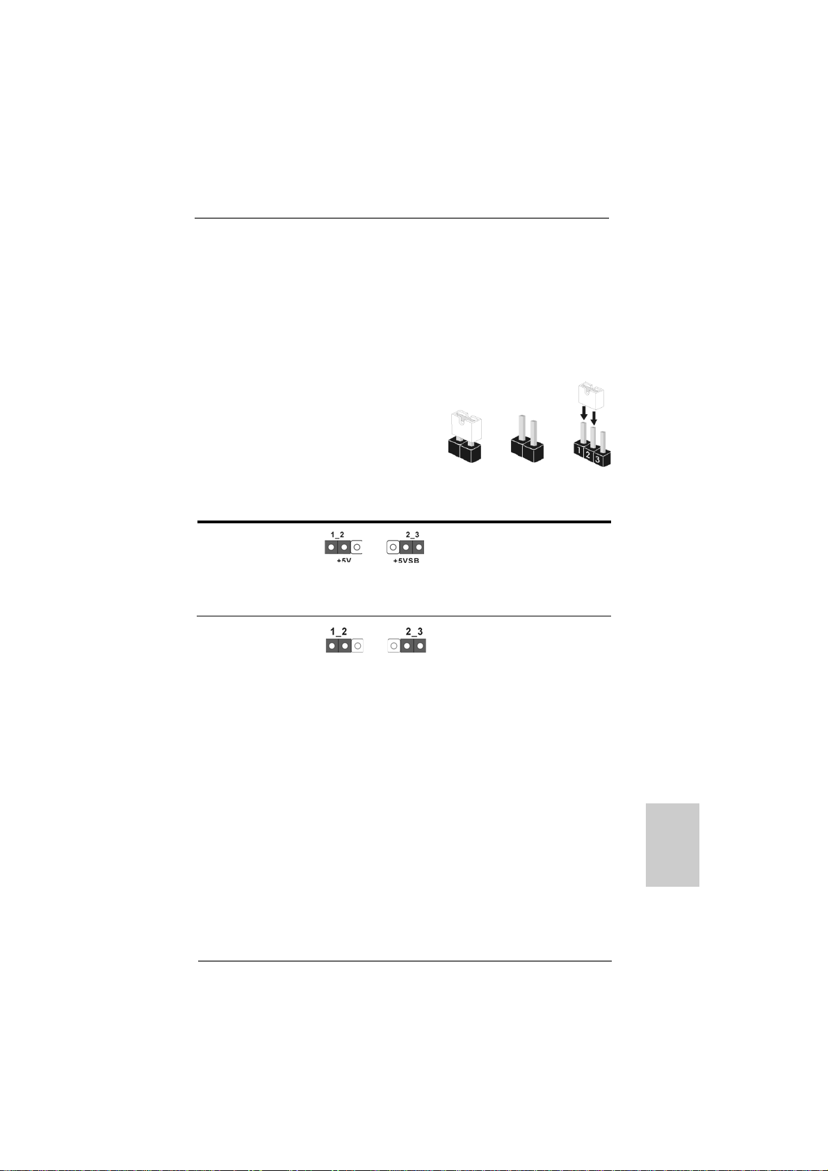
The illustration shows how jumpers are
setup. When the jumper cap is placed on
pins, the jumper is “Short”. If no jumper cap
is placed on pins, the jumper is “Open”. The
illustration shows a 3-pin jumper whose pin1
and pin2 are “Short” when jumper cap is
placed on these 2 pins.
Jumper Setting
PS2_USB_PW1 Short pin2, pin3 to enable
(see p.2/p.3, No. 1) +5VSB (standby) for PS/2 or
USB wake up events.
Note: To select +5VSB, it requires 2 Amp and higher standby current provided by
power supply.
Clear CMOS Jumper
(CLRCMOS1)
(see p.2/p.3, No. 24)
Clear CMOSDefault
OpenShort
Note: CLRCMOS1 allows you to clear the data in CMOS. The data in CMOS includes
system setup information such as system password, date, time, and system
setup parameters. To clear and reset the system parameters to default setup,
please turn off the computer and unplug the power cord from the power
supply. After waiting for 15 seconds, use a jumper cap to short pin2 and pin3
on CLRCMOS1 for 5 seconds. However, please do not clear the CMOS right
after you update the BIOS. If you need to clear the CMOS when you just finish
updating the BIOS, you must boot up the system first, and then shut it down
before you do the clear-CMOS action.
ASRock ALiveNF6G-DVI / ALiveNF6G-VSTA Motherboard
1717
17
1717
EnglishEnglish
EnglishEnglish
English
Page 18
2.7 Onboard Headers and Connectors2.7 Onboard Headers and Connectors
2.7 Onboard Headers and Connectors
2.7 Onboard Headers and Connectors2.7 Onboard Headers and Connectors
Onboard headers and connectors are NOT jumpers. Do NOT place
jumper caps over these headers and connectors. Placing jumper caps
over the headers and connectors will cause permanent damage of the
motherboard!
•
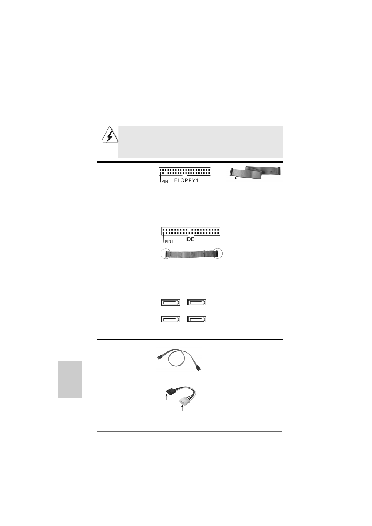
Floppy Connector
(33-pin FLOPPY1)
(see p.2/p.3 No. 10)
the red-striped side to Pin1
Note: Make sure the red-striped side of the cable is plugged into Pin1 side of the
connector.
Primary IDE connector (Blue)
(39-pin IDE1, see p.2/p.3 No. 1 1)
English
EnglishEnglish
EnglishEnglish
connect the blue end
to the motherboard
80-conductor ATA 66/100/133 cable
connect the black end
to the IDE devices
Note: P l e ase re f e r t o t h e i nstruction of your IDE device vendor for the details.
Serial A T AII Connectors These four Serial A T AII (SAT AII)
(SAT AII_1: see p.2/p.3, No. 16) connectors support SATAII
(SAT AII_2: see p.2/p.3, No. 22) or SATA hard disk for internal
(SAT AII_3: see p.2/p.3, No. 14) storage devices. The current
(SAT AII_4: see p.2/p.3, No. 13) SATAII interface allows up to
SAT AII_4
SAT AII_2
SAT AII_3
SAT AII_1
3.0 Gb/s data transfer rate.
Serial A TA (SATA) Either end of the SATA data cable
Data Cable can be connected to the SATA /
(Optional) SATAII hard disk or the SATAII
connector on the motherboard.
Serial ATA (SATA) Please connect the black end of
Power Cable SATA power cable to the power
(Optional) connector on each drive. Then
connect to the SAT A
HDD power connector
connect to the
power supply
connect the white end of SATA
power cable to the power
connector of the power supply.
1818
18
1818
ASRock ALiveNF6G-DVI / ALiveNF6G-VSTA Motherboard
Page 19
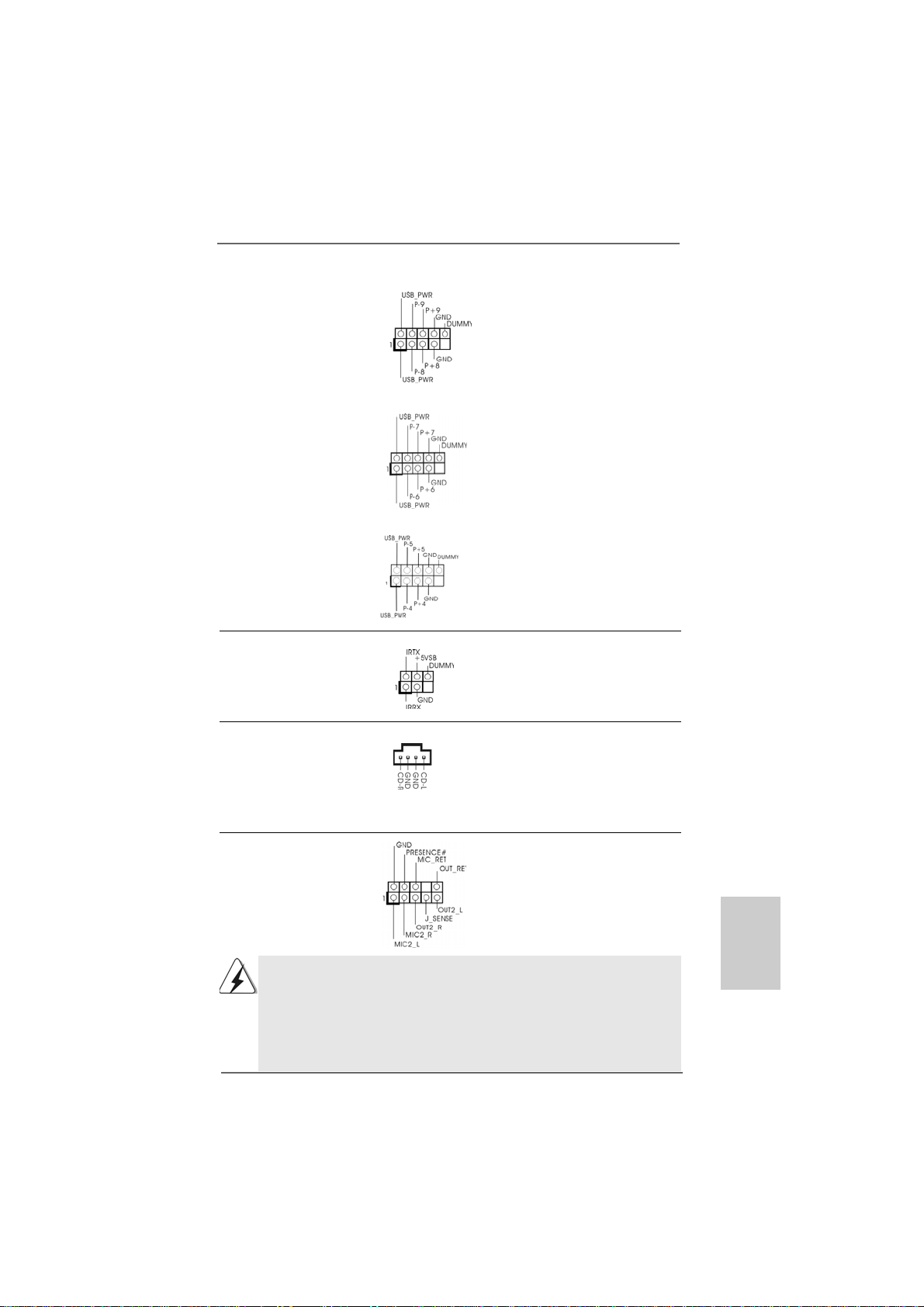
USB 2.0 Headers Besides four default USB 2.0
(9-pin USB8_9) ports on the I/O panel, there are
(see p.2/p.3 No. 19) three USB 2.0 headers on this
motherboard. Each USB 2.0
header cansupport two USB
2.0 ports.
(9-pin USB6_7)
(see p.2/p.3 No. 17)
(9-pin USB4_5)
(see p.2/p.3 No. 20)
Infrared Module Header This header supports an
(5-pin IR1) optional wireless transmitting
(see p.2/p.3 No. 8) and receiving infrared module.
Internal Audio Connectors This connector allows you
(4-pin CD1) to receive stereo audio input
(CD1: see p.2/p.3 No. 29) from sound sources such as
CD1
a CD-ROM, D VD-ROM, TV
tuner card, or MPEG card.
Front Panel Audio Header This is an interface for the front
(9-pin HD_AUDIO1) panel audio cable that allows
(see p.2/p.3, No. 26) convenient connection and
control of audio devices.
1. High Definition Audio supports Jack Sensing, but the panel wire on the
chassis must support HDA to function correctly. Please follow the
instruction in our manual and chassis manual to install your system.
2. If you use AC’97 audio panel, please install it to the front panel audio
header as below:
A. Connect Mic_IN (MIC) to MIC2_L.
B. Connect Audio_R (RIN) to OUT2_R and Audio_L (LIN) to OUT2_L.
ASRock ALiveNF6G-DVI / ALiveNF6G-VSTA Motherboard
1919
19
1919
EnglishEnglish
EnglishEnglish
English
Page 20
C. Connect Ground (GND) to Ground (GND).
D. MIC_RET and OUT_RET are for HD audio panel only. You don’t
need to connect them for AC’97 audio panel.
E. Enter BIOS Setup Utility. Enter Advanced Settings, and then select
Chipset Configuration. Set the Front Panel Control option from
[Auto] to [Enabled].
F. Enter Windows system. Click the icon on the lower right hand
taskbar to enter Realtek HD Audio Manager. Click “Audio I/O”, select
“Connector Settings” , choose “Disable front panel jack
detection”, and save the change by clicking “OK”.
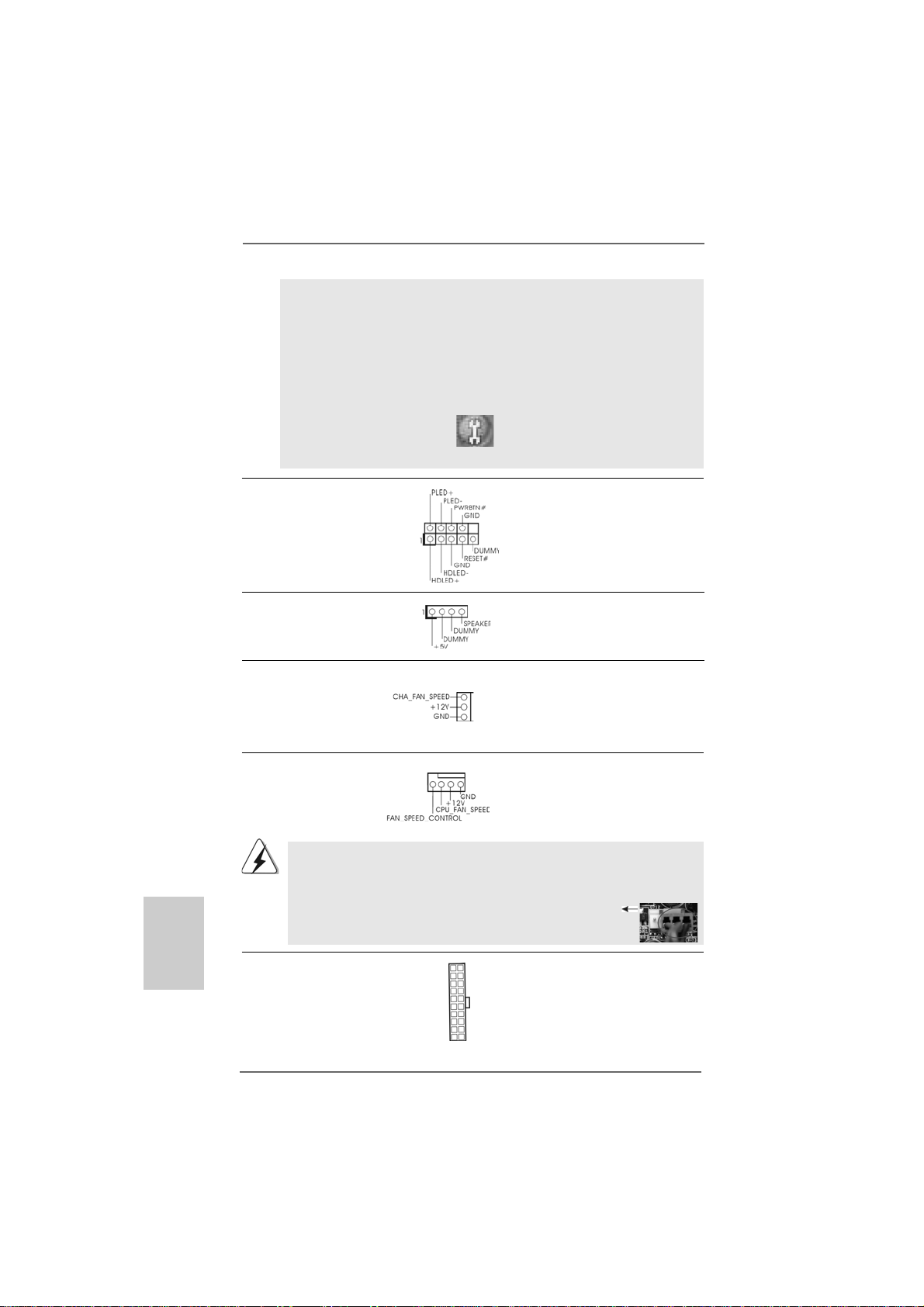
System Panel Header This header accommodates
(9-pin PANEL1) several system front panel
(see p.2/p.3 No. 18) functions.
Chassis Speaker Header Please connect the chassis
(4-pin SPEAKER 1) speaker to this header.
(see p.2/p.3 No. 21)
Chassis Fan Connector P lease connect a chassis fan
(3-pin CHA_FAN1) cable to this connector and
(see p.2/p.3 No. 15) match the black wire to the
ground pin.
English
EnglishEnglish
EnglishEnglish
2020
20
2020
CPU Fan Connector Please connect the CPU fan
(4-pin CPU_FAN1) cable to this connector and
(see p.2/p.3 No. 5) match the black wire to the
4 3 2 1
ground pin.
Though this motherboard provides 4-Pin CPU fan (Quiet Fan) support, the 3-Pin
CPU fan still can work successfully even without the fan speed control function.
If you plan to connect the 3-Pin CPU fan to the CPU fan connector on this
motherboard, please connect it to Pin 1-3.
Pin 1-3 Connected
3-Pin Fan Installation
ATX Power Connector Please connect an ATX power
(20-pin ATXPW R1) supply to this connector.
(see p.2/p.3 No. 32)
ASRock ALiveNF6G-DVI / ALiveNF6G-VSTA Motherboard
Page 21
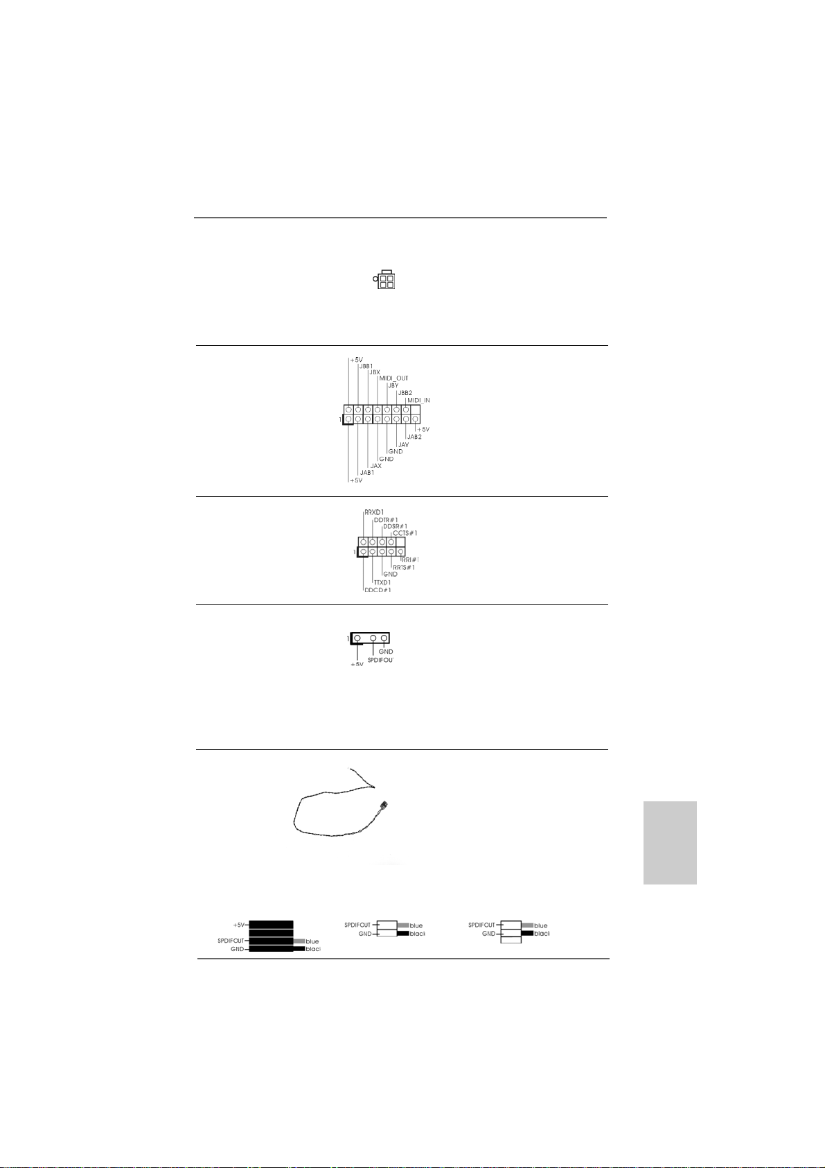
ATX 12V Power Connector Please note that it is necessary
(4-pin A TX12V1) to connect a power supply with
(see p.2/p.3 No. 2) ATX 12V plug to this connector.
Failing to do so will cause power
up failure.
Game Port Hea der Connect a Game cable to this
(15-pin GAME1) header if the Game port bracket
(see p.2/p.3 No. 9) is installed.
Serial port Header This COM1 header
(9-pin COM1) supports a serial port module.
(see p.2/p.3 No.33)
HDMI_SPDIF Header HDMI_SPDIF header, providing
(3-pin HDMI_SPDIF1) SPDIF audio output to HDMI V GA
(see p.2/p.3 No. 27) card, allows the system to
connect HDMI Digital TV/
projector/LCD devices. Please
connect the HDMI_SPDIF
connector of HDMI VGA card to
this header.
HDMI_SPDIF Cable Please connect the black end (A)
(Optional) of HDMI_SPDIF cable to the
C
B
A
HDMI_SPDIF header on the
motherboard. Then connect the
white end (B or C) of
HDMI_SPDIF cable to the
HDMI_SPDIF connector of HDMI
VGA card.
A. black end B. white end (2-pin) C. white end (3-pin)
ASRock ALiveNF6G-DVI / ALiveNF6G-VSTA Motherboard
2121
21
2121
EnglishEnglish
EnglishEnglish
English
Page 22
2.8 HDMI_SPDIF Header Connection Guide2.8 HDMI_SPDIF Header Connection Guide
2.8 HDMI_SPDIF Header Connection Guide
2.8 HDMI_SPDIF Header Connection Guide2.8 HDMI_SPDIF Header Connection Guide
HDMI (High-Definition Multi-media Interfa ce) is an all-digital audio/video specification,
which provides an interface between any compatible digital audio/video source,
such as a set-top box, DVD player, A/V receiver and a compatible digital audio or
video monitor, such as a digital television (DTV). A complete HDMI system requires a
HDMI VGA card and a HDMI ready motherboard with a HDMI_SPDIF header. This
motherboard is equipped with a HDMI_SPDIF header, which provides SPDIF audio
output to HDMI VGA card, allows the system to connect HDMI Digital TV/projector/
LCD devices. To use HDMI function on this motherboard, please carefully follow the
below steps.
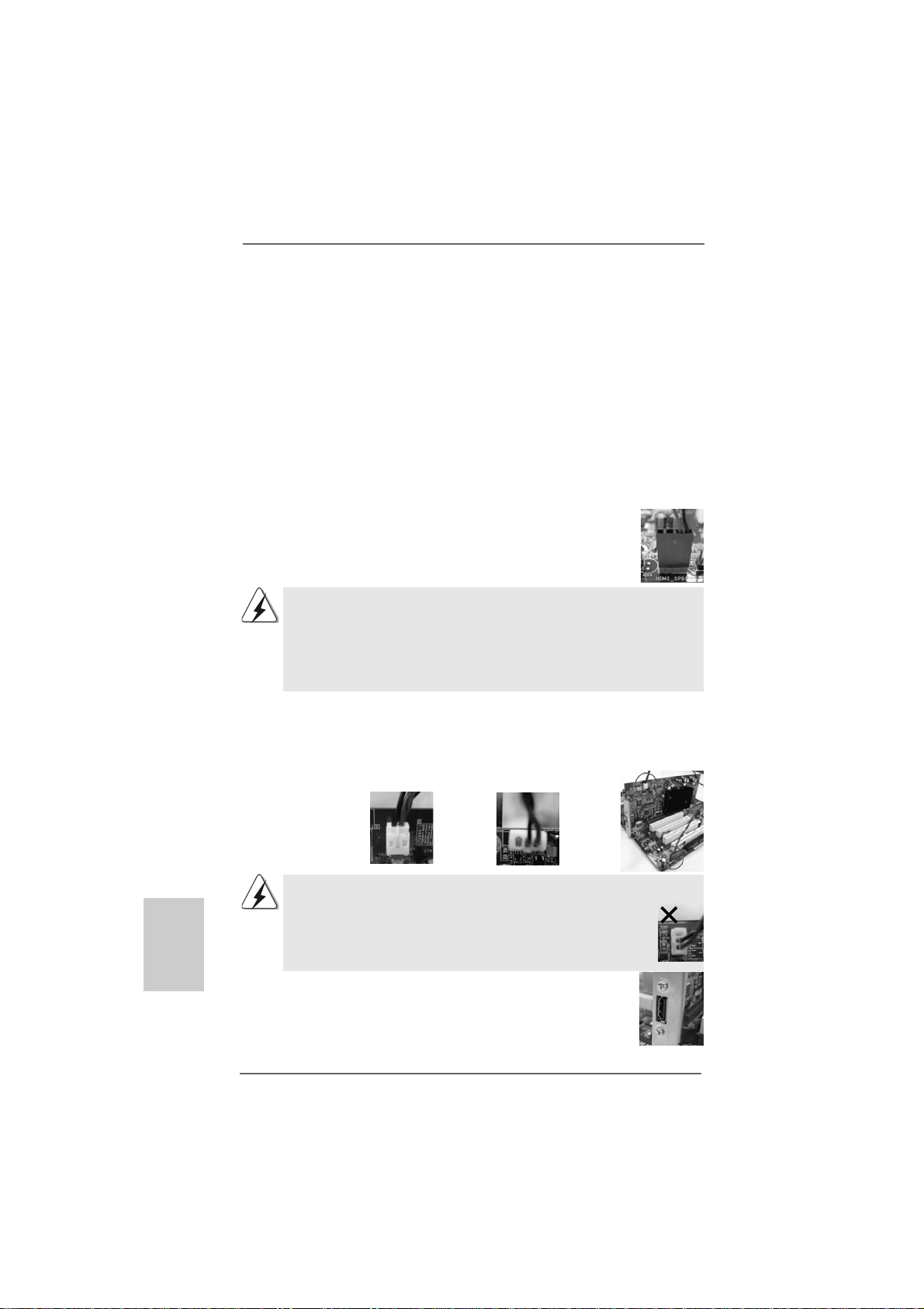
•
Step 1. Install the HDMI VGA card to the PCI Express Graphics slot on this
motherboard. For the proper installation of HDMI VGA card, please refer
to the installation guide on page 13.
Step 2. Connect the black end (A) of HDMI_SPDIF cable to the
HDMI_SPDIF header (HDMI_SPDIF1, yellow, see page 2/page
3, No. 27) on the motherboard.
Make sure to correctly connect the HDMI_SPDIF cable to the motherboard and the
HDMI VGA card according to the same pin definition. For the pin definition of
HDMI_SPDIF header and HDMI_SPDIF ca ble connectors, ple ase refer to page 21. For
the pin definition of HDMI_SPDIF connectors on HDMI VGA card, please refer to the
user manual of HDMI VGA card vendor. Incorrect connection may cause permanent
damage to this motherboard and the HDMI VGA card.
Step 3. Connect the white end (B or C) of HDMI_SPDIF cable to the HDMI_SPDIF
connector of HDMI VGA card. (There are two white ends (2-pin and 3-pin)
on HDMI_SPDIF cable. Please choose the appropri ate white end according
to the HDMI_SPDIF connector of the HDMI VGA card you install.
English
EnglishEnglish
EnglishEnglish
2222
22
2222
white end
(2-pin) (B)
Please do not connect the white end of HDMI_SPDIF cable to the wrong connector
of HDMI VGA card or other VGA card. Otherwise, the motherboard and the
VGA card may be damaged. For example, this picture shows the wrong
example of connecting HDMI_SPDIF cable to the fan connector of PCI
Express VGA card. Please refer to the VGA card user manual for
connector usage in advance.
white end
(3-pin) (C)
Step 4. Connect the HDMI output connector on HDMI VGA card to
HDMI device, such as HDTV. Please refer to the user manual
of HDTV and HDMI VGA card vendor for detailed connection
procedures.
Step 5. Install HDMI VGA card driver to your system.
ASRock ALiveNF6G-DVI / ALiveNF6G-VSTA Motherboard
Page 23
2.92.9
SASA
TT
2.9
2.92.9
Before installing SATAII hard disk to your computer, please carefully read below
SATAII hard disk setup guide. Some default setting of SATAII hard disks may not be
at SATAII mode, which operate with the best performance. In order to enable SATAII
function, please follow the below instruction with different vendors to correctly
adjust your SA TAII hard disk to SATAII mode in advance; otherwise, your SATAII hard
disk may fail to run at SATAII mode.
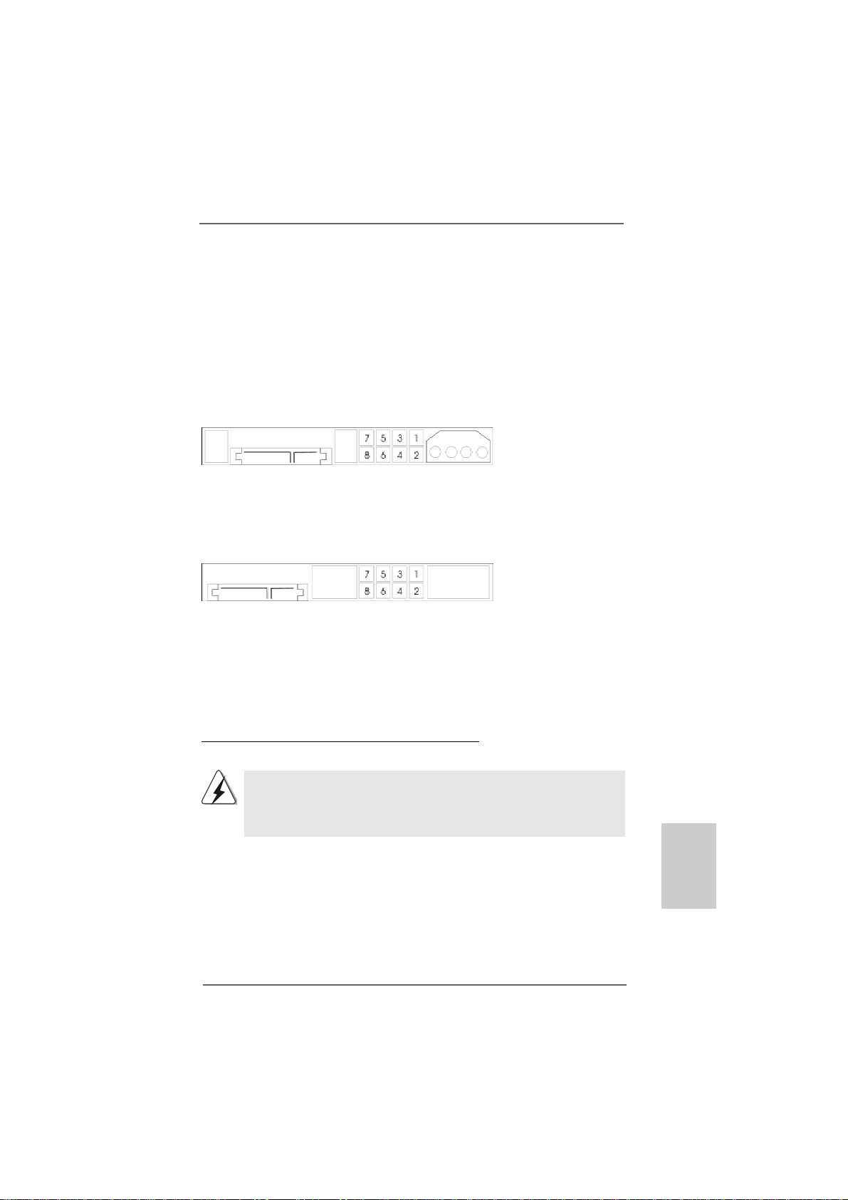
Western Digital
If pin 5 and pin 6 are shorted, SATA 1.5Gb/s will be enabled.
On the other hand, if you want to enable SATAII 3.0Gb/s, please remove the jumpers
from pin 5 and pin 6.
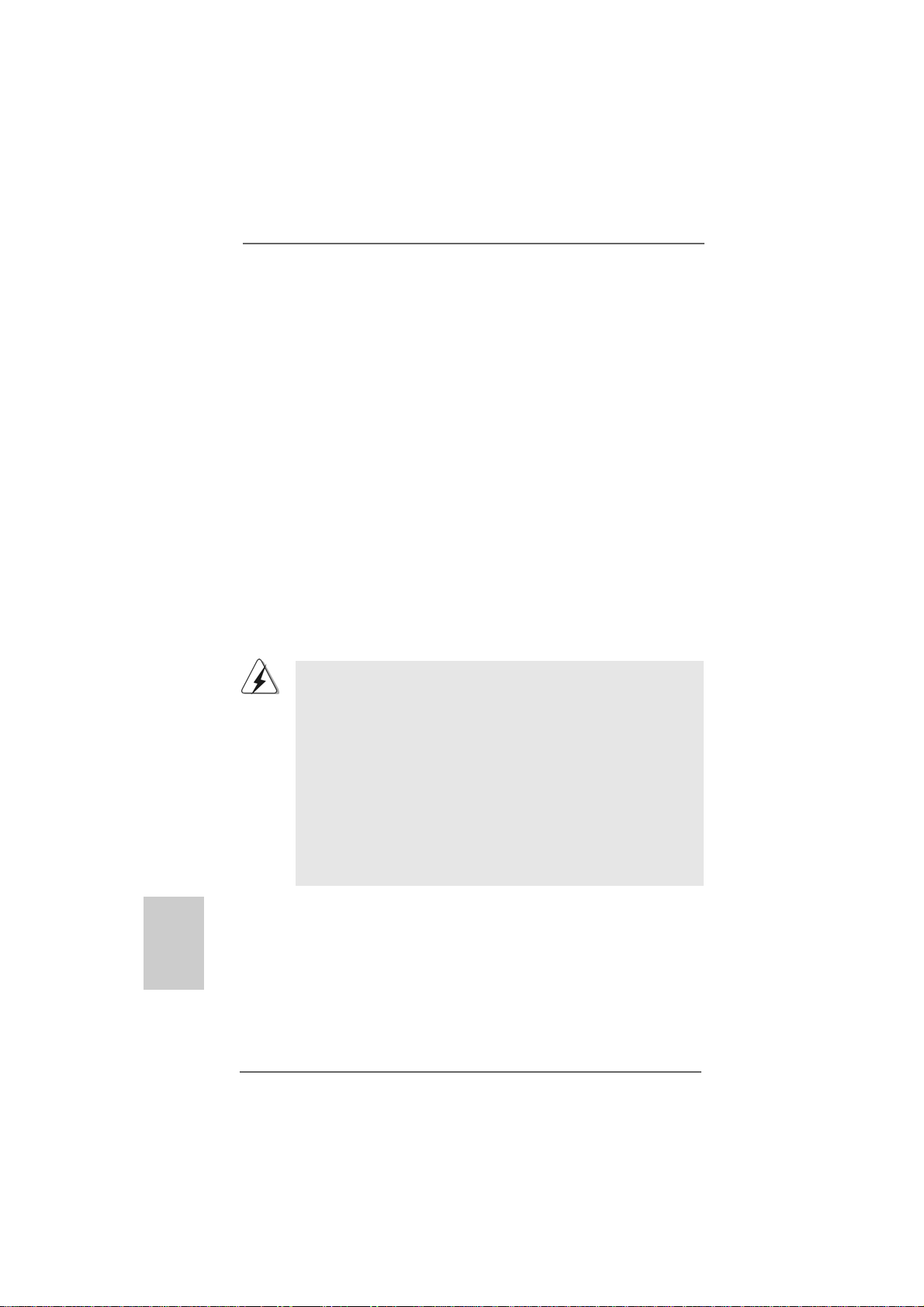
SAMSUNG
If pin 3 and pin 4 are shorted, SATA 1.5Gb/s will be enabled.
On the other hand, if you want to enable SATAII 3.0Gb/s, please remove the jumpers
from pin 3 and pin 4.
AII Hard Disk Setup GuideAII Hard Disk Setup Guide
SA
T
AII Hard Disk Setup Guide
SASA
TT
AII Hard Disk Setup GuideAII Hard Disk Setup Guide
HITACHI
Please use the Feature Tool, a DOS-bootable tool, for changing various ATA features.
Please visit HITACHI’s website for details:
http://www.hitachigst.com/hdd/support/download.htm
The above examples are just for your reference. For different SATAII hard
disk products of different vendors, the jumper pin setting methods may not
be the same. Please visit the vendors’ website for the updates.
ASRock ALiveNF6G-DVI / ALiveNF6G-VSTA Motherboard
2323
23
2323
EnglishEnglish
EnglishEnglish
English
Page 24
2.102.10
2.10
2.102.10
This motherboard adopts NVIDIA® GeForce 6100 / nForce 430 or GeForce 6150SE
/ nForce 430 chipset that supports Serial ATA (SATA) / Serial ATAII (SATAII) hard
disks and RAID functions. You may install SATA / SATAII hard disks on this
motherboard for internal storage devices. This section will guide you to install the
SATA / SATAII hard disks.
STEP 1: Install the SATA / SATAII hard disks into the drive bays of your chassis.
STEP 2: Connect the SATA power cable to the SATA / SATAII hard disk.
STEP 3: Connect one end of the SATA data cable to the motherboard’s SATAII
STEP 4: Connect the other end of the SATA data cable to the SATA / SATAII hard
2.112.11
2.11
2.112.11
This motherboard supports Hot Plug and Hot Swap functions for SATA / SATAII
Devices.
Serial ASerial A
Serial A
Serial ASerial A
InstallationInstallation
Installation
InstallationInstallation
connector.
disk.
Hot Plug and Hot Swap FHot Plug and Hot Swap F
Hot Plug and Hot Swap F
Hot Plug and Hot Swap FHot Plug and Hot Swap F
HDDsHDDs
HDDs
HDDsHDDs
TT
A (SAA (SA
TT
A (SA
A (SAA (SA
A) / Serial AA) / Serial A
T
A) / Serial A
TT
A) / Serial AA) / Serial A
T
TT
NOTE
What is Hot Plug Function?
If the SATA / SATAII HDDs are NOT set for RAID configuration, it is
called “Hot Plug” for the action to insert and remove the SATA / SATAII
HDDs while the system is still power-on and in working condition.
However, please note that it cannot perform Hot Plug if the OS has
been installed into the SATA / SATAII HDD.
TT
AII (SAAII (SA
T
AII (SA
TT
AII (SAAII (SA
unctions for SAunctions for SA
unctions for SA
unctions for SAunctions for SA
TT
AII) Hard DisksAII) Hard Disks
T
AII) Hard Disks
TT
AII) Hard DisksAII) Hard Disks
TT
A / SAA / SA
T
A / SA
TT
A / SAA / SA
TT
T
TT
AIIAII
AII
AIIAII
English
EnglishEnglish
EnglishEnglish
2424
24
2424
What is Hot Swap Function?
If SATA / SATAII HDDs are built as RAID1 then it is called “Hot Swap”
for the action to insert and remove the SATA / SATAII HDDs while the
system is still power-on and in working condition.
2.122.12
Driver Installation GuideDriver Installation Guide
2.12
Driver Installation Guide
2.122.12
Driver Installation GuideDriver Installation Guide
To install the drivers to your system, please insert the support CD to your optical
drive first. Then, the drivers compatible to your system can be auto-detected and
listed on the support CD driver page. Please follow the order from up to bottom
side to install those required drivers. Therefore, the drivers you install can work
properly.
ASRock ALiveNF6G-DVI / ALiveNF6G-VSTA Motherboard
Page 25
2.132.13
HDMR Card and Driver Installation HDMR Card and Driver Installation
2.13
HDMR Card and Driver Installation
2.132.13
HDMR Card and Driver Installation HDMR Card and Driver Installation
If you do not insert HDMR card to this motherboard, and you finish installing all
drivers to your system now, but in the future, you plan to use HDMR card function
on this motherboard, please follow the steps below then.
1. Insert HDMR card to HDMR slot on this motherboard. Please make sure that the
HDMR card is completely seated on the slot.
2. Install HDMR card driver from our support CD to your system.
3. Reboot your system.
2.142.14
Installing WindowsInstalling Windows
2.14
Installing Windows
2.142.14
Installing WindowsInstalling Windows
TMTM
TM
/ Vista/ Vista
/ Vista
/ Vista/ Vista
If you just want to install Windows® 2000, Windows® XP, Windows® XP 64-bit,
Windows® VistaTM or Windows® VistaTM 64-bit on your SATA / SATAII HDDs without
RAID functions, you don’t have to make a SATA / SATAII driver diskette. Besides,
there is no need for you to change the BIOS setting. You can start to install Windows
2000, Windows® XP, Windows® XP 64-bit, Windows® VistaTM or Windows® Vista
64-bit on your system directly.
2.152.15
Installing WindowsInstalling Windows
2.15
Installing Windows
2.152.15
Installing WindowsInstalling Windows
/ Vista/ Vista
/ Vista
/ Vista/ Vista
If you want to install Windows® 2000, Windows® XP, Windows® XP 64-bit, Windows
VistaTM or Windows® VistaTM 64-bit OS on your SATA / SATAII HDDs with RAID
functions, please follow below procedures according to the OS you install.
TMTM
64-bit Without RAID Functions 64-bit Without RAID Functions
64-bit Without RAID Functions
64-bit Without RAID Functions 64-bit Without RAID Functions
The installation procedures for Windows® VistaTM / VistaTM 64-bit are subject to
change. Please visit our website for the updates of Windows® Vista
driver and related information in the future.
TMTM
TM
TMTM
64-bit With RAID Functions 64-bit With RAID Functions
64-bit With RAID Functions
64-bit With RAID Functions 64-bit With RAID Functions
1. The installation procedures for Windows® VistaTM / VistaTM 64-bit are subject to
change. Please visit our website for the updates of Windows® Vista
64-bit driver and related information in the future.
2. Before installing Windows® 2000 to your system, your Windows® 2000 optical
disk is supposed to include SP4. If there is no SP4 included in your disk, please
visit the below website for proper procedures of making a SP4 disk:
http://www.microsoft.com/Windows2000/downloads/servicepacks/sp4/spdeploy.
htm#the_integrated_installation_fmay
®
2000 / XP / XP 64-bit / Vista 2000 / XP / XP 64-bit / Vista
2000 / XP / XP 64-bit / Vista
2000 / XP / XP 64-bit / Vista 2000 / XP / XP 64-bit / Vista
®
2000 / XP / XP 64-bit / Vista 2000 / XP / XP 64-bit / Vista
2000 / XP / XP 64-bit / Vista
2000 / XP / XP 64-bit / Vista 2000 / XP / XP 64-bit / Vista
TMTM
TM
TMTM
TM
/ VistaTM 64-bit
TMTM
TM
TMTM
TM
/ Vista
TM
®
TM
®
EnglishEnglish
EnglishEnglish
English
ASRock ALiveNF6G-DVI / ALiveNF6G-VSTA Motherboard
2525
25
2525
Page 26

English
EnglishEnglish
EnglishEnglish
2.15.1 Installing Windows2.15.1 Installing Windows
2.15.1 Installing Windows
2.15.1 Installing Windows2.15.1 Installing Windows
Functions Functions
Functions
Functions Functions
If you want to install Windows® 2000, Windows® XP or Windows® XP 64-bit on your
SATA / SATAII HDDs with RAID functions, please follow below steps.
STEP 1: Make a SATA / SATAII Driver Diskette.
A. Insert the ASRock Support CD into your optical drive to boot your system.
B. During POST at the beginning of system boot-up, press <F11> key, and
then a window for boot devices selection appears. Please select CDROM as the boot device.
C. When you see the message on the screen, “Generate Serial ATA driver
diskette [YN]?”, press <Y>.
D. Then you will see these messages,
Please insert a blank
formatted diskette into floppy
drive A:
press any key to start
Please insert a floppy diskette into the floppy drive, and press any key.
E. The system will start to format the floppy diskette and copy SATA /
SATAII drivers into the floppy diskette.
STEP 2: Set Up BIOS.
A. Enter BIOS SETUP UTILITY Advanced screen IDE Configuration.
B. Set the “SATA Operation Mode” option to [RAID].
STEP 3: Use “RAID Installation Guide” to set RAID configuration.
Before you start to configure RAID function, you need to check the RAID installation
guide in the Support CD for proper configuration. Please refer to the BIOS RAID
installation guide in the following path in the Support CD:
.. \ RAID Installation Guide
STEP 4: Install Windows® 2000 / Windows® XP / Windows® XP 64-bit OS on
your system.
After step1, 2, 3, you can start to install Windows® 2000 / Windows® XP / Windows
XP 64-bit OS on your system. At the beginning of Windows® setup, press F6 to install
a third-party RAID driver. When prompted, insert the SATA / SATAII driver diskette
containing the NVIDIA® RAID driver. After reading the floppy disk, the driver will be
presented. Select the driver to install according to the mode you choose and the OS
you install.
®
2000 / XP / XP 64-bit With RAID 2000 / XP / XP 64-bit With RAID
2000 / XP / XP 64-bit With RAID
2000 / XP / XP 64-bit With RAID 2000 / XP / XP 64-bit With RAID
®
NOTE. If you install Windows® 2000 / Windows® XP / Windows® XP 64-bit on IDE
HDDs and want to manage (create, convert, delete, or rebuild) RAID functions
on SATA / SATAII HDDs, you still need to set up “SATA Operation Mode” to [RAID] in
BIOS first. Then, please set the RAID configuration by using the Windows RAID
installation guide in the following path in the Support CD:
2626
26
2626
.. \ RAID Installation Guide
ASRock ALiveNF6G-DVI / ALiveNF6G-VSTA Motherboard
Page 27

Vista Vista
Vista
Vista Vista
OS)
TM
TM TM
TM
TM TM
/ Vista/ Vista
/ Vista
/ Vista/ Vista
64-bit OS)
2.15.2 Installing Windows2.15.2 Installing Windows
2.15.2 Installing Windows
2.15.2 Installing Windows2.15.2 Installing Windows
RAID Functions RAID Functions
RAID Functions
RAID Functions RAID Functions
If you want to install Windows® VistaTM or Windows® VistaTM 64-bit on your SATA /
SATAII HDDs with RAID functions, please follow below steps.
STEP 1: Set Up BIOS.
A. Enter BIOS SETUP UTILITY Advanced screen IDE Configuration.
B. Set the “SATA Operation Mode” option to [RAID].
STEP 2: Use “RAID Installation Guide” to set RAID configuration.
Before you start to configure RAID function, you need to check the RAID installation
guide in the Support CD for proper configuration. Please refer to the BIOS RAID
installation guide part of the document in the following path in the Support CD:
.. \ RAID Installation Guide
STEP 3: Install Windows® VistaTM / Windows® VistaTM 64-bit OS on your
system.
Insert the Windows® VistaTM / Windows® VistaTM 64-bit optical disk into the optical
drive to boot your system, and follow the instruction to install Windows® VistaTM /
Windows® VistaTM 64-bit OS on your system. When you see “Where do you want to
install Windows?” page, please insert the ASRock Support CD into your optical drive,
and click the “Load Driver” button on the left on the bottom to load the NVIDIA® RAID
drivers. NVIDIA® RAID drivers are in the following path in our Support CD:
.. \ I386 \ Vista (For Windows® Vista
.. \ AMD64 \ Vista64 (For Windows® Vista
After that, please insert Windows® VistaTM / Windows® VistaTM 64-bit optical disk into
the optical drive again to continue the installation.
®
TM
TMTM
TM
TMTM
64-bit With 64-bit With
64-bit With
64-bit With 64-bit With
NOTE. If you install Windows® VistaTM / Windows® VistaTM 64-bit on IDE HDDs and want to
manage (create, convert, delete, or rebuild) RAID functions on SATA / SATAII HDDs,
you still need to set up “SATA Operation Mode” to [RAID] in BIOS first. Then, plea se set
the RAID configuration by using the Windows RAID installation guide in the following
path in the Support CD:
.. \ RAID Installation Guide
2.162.16
Untied Overclocking TUntied Overclocking T
2.16
Untied Overclocking T
2.162.16
Untied Overclocking TUntied Overclocking T
This motherboard supports Untied Overclocking Technology, which means during
overclocking, FSB enjoys better margin due to fixed PCI / PCIE buses. Before you
enable Untied Overclocking function, please enter “Overclock Mode” option of BIOS
setup to set the selection from [Auto] to [CPU, PCIE, Async.]. Therefore, CPU FSB is
untied during overclocking, but PCI / PCIE buses are in the fixed mode so that FSB can
operate under a more stable overclocking environment.
Please refer to the warning on page 8 for the possible overclocking risk before
you apply Untied Overclocking Technology.
ASRock ALiveNF6G-DVI / ALiveNF6G-VSTA Motherboard
echnologyechnology
echnology
echnologyechnology
2727
27
2727
EnglishEnglish
EnglishEnglish
English
Page 28

3. BIOS Information3. BIOS Information
3. BIOS Information
3. BIOS Information3. BIOS Information
The Flash Memory on the motherboard stores BIOS Setup Utility. When you start up
the computer, please press <F2> during the Power-On-Self-Test (POST) to enter
BIOS Setup utility; otherwise, POST continues with its test routines. If you wish to
enter BIOS Setup after POST, please restart the system by pressing <Ctl> + <Alt> +
<Delete>, or pressing the reset button on the system chassis.
The BIOS Setup program is designed to be user-friendly. It is a menu-driven program,
which allows you to scroll through its various sub-menus and to select among the
predetermined choices. For the detailed information about BIOS Setup, please refer
to the User Manual (PDF file) contained in the Support CD.
English
EnglishEnglish
EnglishEnglish
4. Software Suppor4. Software Suppor
4. Software Suppor
4. Software Suppor4. Software Suppor
This motherboard supports various Microsoft® Windows® operating systems: 2000 /
XP / XP Media Center / XP 64-bit / VistaTM / VistaTM 64-bit. The Support CD that came
with the motherboard contains necessary drivers and useful utilities that will enhance motherboard features.
To begin using the Support CD, insert the CD into your CD-ROM drive. It will display
the Main Menu automatically if “AUTORUN” is enabled in your computer. If the Main
Menu does not appear automatically, locate and double-click on the file “ASSETUP.
EXE” from the “BIN” folder in the Support CD to display the menus.
t CD informationt CD information
t CD information
t CD informationt CD information
2828
28
2828
ASRock ALiveNF6G-DVI / ALiveNF6G-VSTA Motherboard
Page 29
ASRock ALiveNF6G-DVI / ALiveNF6G-VSTA Motherboard
2929
29
2929
Page 30
™
‘ ’ ™
®
®
3030
30
3030
®
ASRock ALiveNF6G-DVI / ALiveNF6G-VSTA Motherboard
Page 31
®
®
ASRock ALiveNF6G-DVI / ALiveNF6G-VSTA Motherboard
3131
31
3131
Page 32
™
®
®
‘ ’ ™
®
®
‘ ’
® ®
®
® ®
®
3232
32
3232
ASRock ALiveNF6G-DVI / ALiveNF6G-VSTA Motherboard
Page 33

®
®
®
®
®
®
®
®
®
ASRock ALiveNF6G-DVI / ALiveNF6G-VSTA Motherboard
3333
33
3333
Page 34
3434
34
3434
ASRock ALiveNF6G-DVI / ALiveNF6G-VSTA Motherboard
Page 35
DDRII_1 DDRII_2 DDRII_3 DDRII_4
( )( )( )( )
(1) - (2) - -
(3)
ASRock ALiveNF6G-DVI / ALiveNF6G-VSTA Motherboard
3535
35
3535
Page 36

3636
36
3636
ASRock ALiveNF6G-DVI / ALiveNF6G-VSTA Motherboard
Page 37

ASRock ALiveNF6G-DVI / ALiveNF6G-VSTA Motherboard
3737
37
3737
Page 38

3838
38
3838
ASRock ALiveNF6G-DVI / ALiveNF6G-VSTA Motherboard
Page 39

®
®
®
ASRock ALiveNF6G-DVI / ALiveNF6G-VSTA Motherboard
3939
39
3939
Page 40

®
®
®
4040
40
4040
ASRock ALiveNF6G-DVI / ALiveNF6G-VSTA Motherboard
Page 41

ASRock ALiveNF6G-DVI / ALiveNF6G-VSTA Motherboard
4141
41
4141
Page 42

SAT AII_4
SAT AII_3
SAT AII_2
SAT AII_1
4242
42
4242
ASRock ALiveNF6G-DVI / ALiveNF6G-VSTA Motherboard
Page 43

CD1
ASRock ALiveNF6G-DVI / ALiveNF6G-VSTA Motherboard
4343
43
4343
Page 44

4 3 2 1
4444
44
4444
ASRock ALiveNF6G-DVI / ALiveNF6G-VSTA Motherboard
Page 45

C
B
A
ASRock ALiveNF6G-DVI / ALiveNF6G-VSTA Motherboard
4545
45
4545
Page 46

4646
46
4646
ASRock ALiveNF6G-DVI / ALiveNF6G-VSTA Motherboard
Page 47

ASRock ALiveNF6G-DVI / ALiveNF6G-VSTA Motherboard
4747
47
4747
Page 48

®
4848
48
4848
ASRock ALiveNF6G-DVI / ALiveNF6G-VSTA Motherboard
Page 49

®
®
®
®
®
®
®
®
®
®
®
®
®
®
®
®
®
®
®
®
®
®
®
®
ASRock ALiveNF6G-DVI / ALiveNF6G-VSTA Motherboard
4949
49
4949
Page 50

®
® ®
® ® ®
®
®
® ®
®
®
®
®
5050
50
5050
ASRock ALiveNF6G-DVI / ALiveNF6G-VSTA Motherboard
Page 51

®
®
®
®
®
® ®
®
®
®
®
®
ASRock ALiveNF6G-DVI / ALiveNF6G-VSTA Motherboard
5151
51
5151
Page 52

® ®
5252
52
5252
ASRock ALiveNF6G-DVI / ALiveNF6G-VSTA Motherboard
Page 53

X O O O O O
X O O O O O
O:
X:
ASRock ALiveNF6G-DVI / ALiveNF6G-VSTA Motherboard
5353
53
5353
Page 54

1. Einführung1. Einführung
1. Einführung
1. Einführung1. Einführung
Wir danken Ihnen für den Kauf des ASRock ALiveNF6G-DVI / ALiveNF6G-VSTA
Motherboard, ein zuverlässiges Produkt, welches unter den ständigen, strengen
Qualitätskontrollen von ASRock gefertigt wurde. Es bietet Ihnen exzellente Leistung
und robustes Design, gemäß der Verpflichtung von ASRock zu Qualität und Halbarkeit.
Diese Schnellinstallationsanleitung führt in das Motherboard und die schrittweise
Installation ein. Details über das Motherboard finden Sie in der Bedienungsanleitung
auf der Support-CD.
Da sich Motherboard-Spezifikationen und BIOS-Software verändern können,
kann der Inhalt dieses Handbuches ebenfalls jederzeit geändert werden. Für
den Fall, dass sich Änderungen an diesem Handbuch ergeben, wird eine neue
Version auf der ASRock-Website, ohne weitere Ankündigung, verfügbar sein.
Die neuesten Grafikkarten und unterstützten CPUs sind auch auf der
ASRock-Website aufgelistet.
ASRock-Website: http://www.asrock.com
1.1 Kartoninhalt
ASRock ALiveNF6G-DVI / ALiveNF6G-VSTA Motherboard
(Micro ATX-Formfaktor: 24.4 cm x 24.4 cm; 9.6 Zoll x 9.6 Zoll)
ASRock ALiveNF6G-DVI / ALiveNF6G-VSTA Schnellinstallationsanleitung
ASRock ALiveNF6G-DVI / ALiveNF6G-VSTA Support-CD
Ein 80-adriges Ultra-ATA 66/100/133 IDE-Flachbandkabel
Ein Flachbandkabel für ein 3,5-Zoll-Diskettenlaufwerk
Ein Seriell-ATA- (SATA) Datenkabel (Option)
Ein Seriell-ATA (SATA) Festplattennetzkabel (Option)
Ein HDMI_SPDIF-Kabel (Option)
Ein HD 8CH I/O Shield
Ein COM Port-Anschlusshalter
Ein HDMR-Karte (Option)
Eine DVI Graphics-SI-Karte (nur für ALiveNF6G-DVI)
Deutsch
DeutschDeutsch
DeutschDeutsch
5454
54
5454
1.21.2
SpezifikationenSpezifikationen
1.2
Spezifikationen
1.21.2
SpezifikationenSpezifikationen
Plattform - Micro ATX-Formfaktor: 24.4 cm x 24.4 cm; 9.6 Zoll x 9.6 Zoll
CPU - AM2 Sockel, unterstützt AMD AthlonTM 64FX / 64X2 / 64 und
Sempron Prozessoren
- AMD LIVE!TM-bereit
- Unterstützt Cool ‘n’ Quiet™-Technologie von AMD
(siehe VORSICHT 1)
- FSB 1000 MHz (2.0 GT/s)
ASRock ALiveNF6G-DVI / ALiveNF6G-VSTA Motherboard
Page 55

- Unterstützt Untied-Übertaktungstechnologie
(siehe VORSICHT 2)
- Unterstützt Hyper-Transport-Technologie
Chipsatz - NVIDIA® GeForce 6100 / nForce 430 oder
GeForce 6150SE / nForce 430 (siehe VORSICHT 3)
Speicher - Unterstützung von Dual-Kanal-Speichertechnologie
(siehe VORSICHT 4)
- 4 x Steckplätze für DDRII
- Unterstützt DD RII800/667/533
- Max. 8GB (siehe VORSICHT 5)
Hybrid Booster - Schrittloser CPU-Frequenz-Kontrolle (siehe VORSICHT 6)
- ASRock U-COP (siehe VORSICHT 7)
- Boot Failure Guard (B.F.G. – Systemstartfehlerschutz)
- ASRock AM2 Boost: ASRocks patentgeschützte T echnologie
zur Erhöhung der Arbeitsspeicherleistung um bis zu 12,5%
(siehe VORSICHT 8)
Erweiterungs- - 2 x PCI -Steckplätze
steckplätze - 1 x PCI Express x 16-Steckplätze
- 1 x PCI Express x 1-Steckplätze
- 1 x HDMR-Steckplätze
Onboard-VGA - Integrierter NVIDIA® GeForce6 DX9.0 VGA Grafikchi p
- Pixel Shader 3.0
- Maximal gemeinsam genutzter Speicher 256 MB
- Dual-VGA-Ausga ng: Unterstützt DVI-D- und D-Sub-
Anschlüsse mit DVI Graphics-SI-Karte mittels unabhängiger
Display-Controller (ALiveNF6G-DVI)
Audio - 7.1 CH Windows® VistaTM Premium Level HD Audio
(ALC888 Audio Codec)
LAN - Gigabit LAN 10/100/1000 Mb/s (ALiveNF6G-DVI)
- Giga PHY Realtek RTL8211B (ALiveNF6G-DVI)
- Realtek PHY RTL8201CL (ALiveNF6G-VSTA)
- Speed: 10/100 Ethernet (ALiveNF6G-VSTA)
- Unterstützt Wake-On-LAN
E/A-Anschlüsse HD 8CH I/O
an der - 1 x PS/2-Mausanschluss
Rückseite - 1 x PS/2-Tastaturanschluss
- 1 x VGA port
- 1 x Paralleler port: Unterstützung für ECP / EPP
- 4 x Standard-USB 2.0-Anschlüsse
- 1 x RJ-45 port
ASRock ALiveNF6G-DVI / ALiveNF6G-VSTA Motherboard
5555
55
5555
DeutschDeutsch
DeutschDeutsch
Deutsch
Page 56

Deutsch
DeutschDeutsch
DeutschDeutsch
- HD Audiobuchse: Lautsprecher seitlich / Lautsprecher hinten
/ Mitte/Bass / Audioeingang/ Lautsprecher vorne / Mikrofon
(siehe VORSICHT 9)
Anschlüsse - 4 x SATAII-Anschlüsse, unterstützt bis 3.0 Gb/s
Datenübertragungsrate, unterstützt RAID (RAID 0, RAID 1,
RAID 0+1, RAID 5, JBOD), NCQ und “Hot Plug” Funktionen
(siehe VORSICHT 10)
- 1 x ATA133 IDE-Anschlüsse (Unterstützt bis 2 IDE-Geräte)
- 1 x FDD-Anschlüsse
- 1 x Infrarot-Modul-Header
- 1 x Game-Anschluss
- 1 x COM-Anschluss-Header
- 1 x HDMI_SPDIF-Anschluss
- CPU/Gehäuse-Lüfteranschluss
- 20-pin ATX-Netz-Header
- 4-pin anschluss für 12V-ATX-Netzteil
- Interne Audio-Anschlüsse
- Anschluss für Audio auf der Gehäusevorderseite
- 3 x USB 2.0-Anschlüsse (Unterstützung 6
zusätzlicher USB 2.0-Anschlüsse) (siehe VORSICHT 11)
BIOS - 4Mb AMI BIOS
- AMI legal BIOS mit Unterstützung für “Plug and Play”
- ACPI 1.1-Weckfunktionen
- JumperFree-Modus
- SMBIOS 2.3.1
Support-CD - Treiber, Dienstprogramme, Antivirussoftware
(Probeversion)
Hardware Monitor - Interner CPU-Temperatursensor
- CPU-Umgebungstemperatursensor
- Motherboardtemperaturerkennung
- Drehzahlmessung für CPU-Lüfter
- Drehzahlmessung für Gehäuselüfter
- CPU-Lüftergeräuschdämpfung
- Spannungsüberwachung: +12V, +5V, +3.3V, Vcore
Betriebssysteme - Unterstützt Microsoft® Windows® 2000 / XP / XP Media
Center / XP 64-Bit / VistaTM / VistaTM 64-Bit
(siehe VORSICHT 12)
Zertifizierungen - FCC, CE, WHQL
5656
56
5656
ASRock ALiveNF6G-DVI / ALiveNF6G-VSTA Motherboard
Page 57

WARNUNG
Beachten Sie bitte, dass Overclocking, einschließlich der Einstellung im BIOS, Anwenden
der Untied Overclocking-Technologie oder Verwenden von Overclocking-W erkzeugen von
Dritten, mit einem gewissen Risiko behaftet ist. Overclocking kann sich nachteilig auf die
Stabilität Ihres Systems auswirken oder sogar Komponenten und Geräte Ihres Systems
beschädigen. Es geschieht dann auf eigene Gefahr und auf Ihre Kosten. Wir übernehmen
keine Verantwortung für mögliche Schäden, die aufgrund von Overclocking verursacht
wurden.
VORSICHT!
1. Um Energie zu sparen, wird dringendst empfohlen, die Cool ‘n’ Quiet™Technologie von AMD im Windows-System zu aktivieren. Siehe ANHANG
auf Seite 50 des “Handbuchs” auf der Support-CD für Hinweise zur
Aktivierung der Cool ‘n’ Quiet™-Technologie von AMD.
2. Dieses Motherboard unterstützt die Untied-Übertaktungstechnologie.
Unter “Entkoppelte Übertaktungstechnologie” auf Seite 79 finden Sie
detaillierte Informationen.
3. Sowohl NVIDIA® GeForce 6100 / nForce 430 und GeForce 6150SE / nForce
430 beziehen sich auf denselben Chipsatz. Wenn Sie einen NVIDIA®-Treiber
ab Version 91.63 unter Windows® 2000 / XP / XP 64-bit oder einen NVIDIA®Treiber ab Version 97.19 unter Windows® Vista™ / Vista™ 64-bit installieren,
lautet der Chipsatzname GeForce 6150SE / nForce 430 statt GeForce 6100 /
nForce 430. Allerdings haben die Unterschiede beim Gerätenamen unter
Windows® keinen Einfluss auf Spezifikationen und Leistungsumfang des
Motherboards.
4. Dieses Motherboard unterstützt Dual-Kanal-Speichertechnologie. Vor
Implementierung der Dual-Kanal-Speichertechnologie müssen Sie die
Installationsanleitung für die Speichermodule auf Seite 60 zwecks richtiger
Installation gelesen haben.
5. Durch Betriebssystem-Einschränkungen kann die tatsächliche Speichergröße
weniger als 4 GB betragen, da unter Windows® XP und Windows® Vista™
etwas Speicher zur Nutzung durch das System reserviert wird. Unter Windows® XP 64-bit und Windows® Vista™ 64-bit mit 64-Bit-CPU besteht diese
Einschränkung nicht.
6. Obwohl dieses Motherboard stufenlose Steuerung bietet, wird
Overclocking nicht empfohlen. Frequenzen, die von den empfohlenen
CPU-Busfrequenzen abweichen, können Instabilität des Systems
verursachen oder die CPU beschädigen.
7. Wird eine Überhitzung der CPU registriert, führt das System einen
automatischen Shutdown durch. Bevor Sie das System neu starten, prüfen
Sie bitte, ob der CPU-Lüfter am Motherboard richtig funktioniert, und stecken
Sie bitte den Stromkabelstecker aus und dann wieder ein. Um die
Wärmeableitung zu verbessern, bitte nicht vergessen, etwas Wärmeleitpaste
zwischen CPU und Kühlkörper zu sprühen.
8. Dieses Motherboard unterstützt die ASRock AM2 Boost
Übertaktungstechnologie. Wenn Sie diese Funktion im BIOS-Setup
aktivieren, wird die Arbeitsspeicherleistung um bis zu 12,5% gesteigert. Die
ASRock ALiveNF6G-DVI / ALiveNF6G-VSTA Motherboard
5757
57
5757
DeutschDeutsch
DeutschDeutsch
Deutsch
Page 58

Wirkung hängt aber von der verwendeten AM2 CPU ab. Diese Funktion
übertaktet die Standardfrequenz des Chipsatz und der CPU. Dennoch
gewähren wir die Systemstabilität nicht bei allen CPU/DRAMKonfigurationen. Wird Ihr System nach dem Aktivieren der AM2 BoostFunktion unstabil, dann ist diese Funktion wahrscheinlich nicht für Ihr
System geeignet. Sie können diese Funktion deaktivieren, um die Stabilität
Ihres System zu bewahren.
9. For microphone input, this motherboard supports both stereo and mono
modes. For audio output, this motherboard supports 2-channel, 4-channel,
6-channel, and 8-channel modes. Please check the table on page 4 for
proper connection.
10. Bevor Sie eine SATA II Festplatte mit dem SATA II Anschluss verbinden,
lesen Sie bitte die “Anleitung zur SATA II Festplatteneinrichtung“ auf
Seite 74, um Ihre SATA II Festplatte in den SATA II Modus umzuschalten.
SATA-Festplatten können Sie auch direkt mit dem SATA II-Anschluss
verbinden.
11. Das Power Management für USB 2.0 arbeitet unter Microsoft® Windows
VistaTM 64-Bit / VistaTM / XP 64-Bit / XP SP1 oder SP2/2000 SP4
einwandfrei.
12. Der Microsoft® Windows® VistaTM / VistaTM 64-Bit Treiber wird ständig
aktualisiert. Sobald wir den neuesten Treiber haben, stellen wir ihn auf
unserer Website zur Verfügung. Bitte besuchen Sie unsere Website für
den Microsoft® Windows® VistaTM / VistaTM 64-Bit Treiber und verwandte
Informationen.
ASRock-Website http://www.asrock.com
®
Deutsch
DeutschDeutsch
DeutschDeutsch
5858
58
5858
1.31.3
Minimale Hardwarevorausetzungen für WindowsMinimale Hardwarevorausetzungen für Windows
1.3
Minimale Hardwarevorausetzungen für Windows
1.31.3
Minimale Hardwarevorausetzungen für WindowsMinimale Hardwarevorausetzungen für Windows
TMTM
TM
TMTM
VistaVista
Vista
VistaVista
Premium und Basic Logo Premium und Basic Logo
Premium und Basic Logo
Premium und Basic Logo Premium und Basic Logo
Systemintegratoren und Anwender unseres Motherboards, die ihre
Rechner auf die Vergabe des Windows® VistaTM Premium und Basic Logos vorbereiten möchten, finden die minimalen
Hardwarevoraussetzungen in der folgenden Tabelle.
CPU Sempron 2800+
Speicher 512 MB x 2 Dual Channel (Premium)
512 MB Single Channel (Basic)
256 MB x 2 Dual Channel (Basic)
* Wenn Sie eine integrierte VGA-Karte mit einem Gesamtsystemspeicher von 512 MB
verwenden und vorhaben, das Windows® VistaTM Basic-Logo zu verwenden, stellen
Sie bitte den gemeinsam genutzten Speicher der integrierten VGA-Karte auf 64 MB.
Wenn Sie den integrierten VGA-Chip mit einer Gesamtsystemspeichergröße von
512MB verwenden und das Windows® VistaTM Premium oder Basic Logo vorlegen
möchten, dann stellen Sie bitte die Größe des dem integrierten VGA-Chip
freizugebenden Arbeitsspeichers auf 128MB oder noch mehr ein.
* Sofern Sie eine externe Grafikkarte mit diesem Motherboard verwenden möchten,
lesen Sie bitte unter Premium Discrete-Anforderungen auf unseren Internetseiten
nach: http://www.asrock.com
ASRock ALiveNF6G-DVI / ALiveNF6G-VSTA Motherboard
®
Page 59

2. Installation2. Installation
2. Installation
2. Installation2. Installation
Sicherheitshinweise vor der MontageSicherheitshinweise vor der Montage
Sicherheitshinweise vor der Montage
Sicherheitshinweise vor der MontageSicherheitshinweise vor der Montage
Bitte nehmen Sie die folgende Sicherheitshinweise zur Kenntnis,
bevor Sie das Motherboard einbauen oder Veränderungen an den
Einstellungen vornehmen.
1. Trennen Sie das System vom Stromnetz, bevor Sie eine
Systemkomponente berühren, da es sonst zu schweren Schäden am
Motherboard oder den sonstigen internen, bzw. externen Komponenten
kommen kann.
2. Um Schäden aufgrund von statischer Elektrizität zu vermeiden, das
Motherboard NIEMALS auf einen Teppich o.ä.legen. Denken Sie außerem
daran, immer ein geerdetes Armband zu tragen oder ein geerdetes Objekt
aus Metall zu berühren, bevor Sie mit Systemkomponenten hantieren.
3. Halten Sie Komponenten immer an den Rändern und vermeiden Sie
Berührungen mit den ICs.
4. Wenn Sie Komponenten ausbauen, legen Sie sie immer auf eine
antistatische Unterlage, oder zurück in die Tüte, mit der die Komponente
geliefert wurde.
5. Wenn Sie das Motherboard mit den Schrauben an dem Computergehäuse
befestigen, überziehen Sie bitte die Schrauben nicht! Das Motherboard
kann sonst beschädigt werden.
2.1 CPU Installation2.1 CPU Installation
2.1 CPU Installation
2.1 CPU Installation2.1 CPU Installation
Schritt 1: Öffnen Sie den CPU-Sockel, indem sie den Hebel leicht zur Seite und
dann nach oben ziehen, auf einen Winkel von 90°.
Schritt 2: Positionieren Sie die CPU genau so über dem Sockel, dass sich die
Ecke der CPU mit dem goldenen Dreie ck exakt über der Ecke des
Sockels befindet, die mit einem kleinen Dreieck gekennzeichnet ist.
Schritt 3: Drücken Sie die CPU vorsichtig in den Sockel.
Die CPU sollte problemlos in den Sockel passen. Drücken Sie die CPU
nicht mit Gewalt in den Sockel, damit sich die Pins nicht verbiegen.
Überprüfen Sie die Ausrichtung und suchen nach verbogenen Pins,
sollte die CPU nicht in den Sockel passen.
Schritt 4: Wenn die CPU korrekt im Sockel sitzt, leicht mit dem Finger
draufdrücken und gleichzeitig den Hebel nach unten drücken, bis er
hörbar einrastet.
Schritt 5: Installieren Sie einen aktiven CPU-Kühler, der die gesamte Fläche der
CPU abdeckt und eine ausreichende Wärmeableitung für den von
Ihnen verwendeten CPU-Typ bietet. Weitere Hinweise finden Sie der
Installationsanleitung für Ihren CPU-Kühler.
ASRock ALiveNF6G-DVI / ALiveNF6G-VSTA Motherboard
5959
59
5959
DeutschDeutsch
DeutschDeutsch
Deutsch
Page 60

2.2 Installation der Speichermodule (DIMM)2.2 Installation der Speichermodule (DIMM)
2.2 Installation der Speichermodule (DIMM)
2.2 Installation der Speichermodule (DIMM)2.2 Installation der Speichermodule (DIMM)
Die Motherboards ALiveNF6G-VSTA / ALiveNF6G-DVI bieten vier 240-pol. DDRII
(Double Data Rate) DIMM-Steckplätze und unterstützen die Dual-KanalSpeichertechnologie. Für die Dual-Kanalkonfiguration dürfen Sie nur identische
(gleiche Marke, Geschwindigkeit, Größe und gleicher Chiptyp) DDRII DIMM-Paare in
den Steckplätzen gleicher Farbe installieren. Mit anderen Worten, sie müssen ein
identisches DDRII DIMM-Paar im Dual-Kanal A (DDRII_1 und DDRII_2; gelbe
Steckplätze, siehe Seite 2/3 Nr. 6) oder ein identisches DDRII DIMM-Paar i m DualKanal B (DDRII_3 und DDRII_4; orange Steckplätze, siehe Seite 2/3 Nr. 7)
installieren, damit die Dual-Kanal-Speichertechnologie aktiviert werden kann. Auf
diesem Motherboard können Sie auch vier DDRII DIMMs für eine DualKanalkonfiguration installieren. Auf diesem Motherboard können Sie auch vier
DDRII DIMM-Module für e ine Dual-Kanalkonfiguration installieren, wobei Sie bitte in
allen vier Steckplätzen identische DD RII DIMM-Module installieren. Beziehen Sie
sich dabei auf die nachstehende Konfigurationstabelle für Dual-Kanalspeicher.
Dual-Kanal-Speicherkonfigurationen
DDRII_1 DDRII_2 DDRII_3 DD RII_4
(gelbe Steckplätze) (gelbe Steckplätze) (orange Steckplätze) (orange Steckplätze)
(1) Bestückt Bestückt - (2 ) - - Bestückt Bestückt
(3) Bestückt Bestückt Bestückt Bestückt
Deutsch
DeutschDeutsch
DeutschDeutsch
6060
60
6060
* Für Konfiguration (3) installieren Sie bitte identische DDRII DIMMs in allen vier
Steckplätzen.
1. Wenn Sie zwei Speichermodule installieren möchten, verwenden Sie
dazu für optimale Kompatibilität und Stabilität Steckplätze gleicher
Farbe. Installieren Sie die beiden Speichermodule also entweder in
den gelbe Steckplätzen (DDRII_1 und DDRII_ 2) oder den orange
Steckplätzen (DDRII_3 und DDRII_4).
2. Wenn nur ein Speichermodul oder drei Speichermodule in den DDRII
DIMM-Steckplätzen auf diesem Motherboard installiert sind, kann es
die Dual-Kanal-Speichertechnologie nicht aktivieren.
3. Ist ein Speichermodulpaar NICHT im gleichen “Dual-Kanal” installiert,
z.B. ein Speichermodulpaar wird in DDRII_1 und DDRII_3 installiert,
kann es die Dual-Kanal-Speichertechnologie nicht aktivieren.
4. Es ist nicht zulässig, DDR in einen DDRII Steckplatz zu installieren;
andernfalls könnten Motherboard und DIMMs beschädigt werden.
ASRock ALiveNF6G-DVI / ALiveNF6G-VSTA Motherboard
Page 61

Einsetzen eines DIMM-ModulsEinsetzen eines DIMM-Moduls
Einsetzen eines DIMM-Moduls
Einsetzen eines DIMM-ModulsEinsetzen eines DIMM-Moduls
Achten Sie darauf, das Netzteil abzustecken, bevor Sie DIMMs oder
Systemkomponenten hinzufügen oder entfernen.
Schritt 1: Öffnen Sie einen DIMM-Slot, indem Sie die se itlichen Clips nach außen
drücken.
Schritt 2: Richten Sie das DIMM-Modul so über dem Slot aus, dass das Modul mit
der Kerbe in den Slot passt.
Die DIMM-Module passen nur richtig herum eingelegt in die
Steckplätze. Falls Sie versuchen, die DIMM-Module mit Gewalt falsch
herum in die Steckplätze zu zwingen, führt dies zu dauerhaften
Schäden am Mainboard und am DIMM-Modul.
Schritt 3: Drücken Sie die DIMM-Module fest in die Steckplätze, so dass die
Halteklammern an beiden Enden des Moduls einschnappen und das
DIMM-Modul fest an Ort und Stelle sitzt.
ASRock ALiveNF6G-DVI / ALiveNF6G-VSTA Motherboard
6161
61
6161
DeutschDeutsch
DeutschDeutsch
Deutsch
Page 62

Deutsch
DeutschDeutsch
DeutschDeutsch
2.32.3
Erweiterungssteckplätze (PCI-Steckplätze, HDMR-Erweiterungssteckplätze (PCI-Steckplätze, HDMR-
2.3
Erweiterungssteckplätze (PCI-Steckplätze, HDMR-
2.32.3
Erweiterungssteckplätze (PCI-Steckplätze, HDMR-Erweiterungssteckplätze (PCI-Steckplätze, HDMRSteckplatz und PCI Express-Steckplätze)Steckplatz und PCI Express-Steckplätze)
Steckplatz und PCI Express-Steckplätze)
Steckplatz und PCI Express-Steckplätze)Steckplatz und PCI Express-Steckplätze)
Es gibt einen 2 PCI-Steckplätze, 1 HDMR-Steckplätze und 2 PCI ExpressSteckplätze am ALiveNF6G-DVI / ALiveNF6G-VSTA Motherboard.
PCI-Slots: PCI-Slots werden zur Installation von Erweiterungskarten mit dem
32bit PCI-Interface genutzt.
HDMR-Slot: Der HDMR-Steckplatz dient zur Aufnahme der ASRock HDMR-Karte
(Option) mit v.92 Modem-Funktionalität. Der HDMR-Steckplatz wird
gemeinsa m mit dem PCIE2-Steck platz genutzt. Daher können Sie
entweder den PCIE2- oder den HDMR-Steckplatz nutzen.
PCI Express-Slots: PCIE1 (PCIE x16-Steckplatz) wird für PCI Express-Karten mit
x16 Lane Width-Grafikkarten oder einer ASRock DVI
Graphics-SI-Karte verwendet (ALiveNF6G-DVI).
PCIE2 (PCIE x1-Steckplatz) wird für PCI Express Grafikkarten mit x1-Busbreite verwendet wie Gigabit LAN Karten, SATA2-Karten, usw. eingesetzt.
Sie können nur eine PCI Express VGA-Karte oder DVI Graphics-SI-Karte für
Installation in PCIE1 (PCIE x16-Steckplatz) auf dem ALiveNF6G-DVI-
Motherboard wählen.
Einbau einer ErweiterungskarteEinbau einer Erweiterungskarte
Einbau einer Erweiterungskarte
Einbau einer ErweiterungskarteEinbau einer Erweiterungskarte
Schritt 1: Bevor Sie die Erweiterungskarte installieren, vergewissern Sie sich,
dass das Netzteil ausgeschaltet und das Netzkabel abgezogen ist.
Bitte lesen Sie die Dokumentation zur Erweiterungskarte und nehmen
Sie nötige Hardware-Einstellungen für die Karte vor, ehe Sie mit der
Installation beginnen.
Schritt 2: Entfernen Sie das Abdeckungsblech (Slotblende) von dem
Gehäuseschacht (Slot) , den Sie nutzen möchten und behalten die
Schraube für den Einbau der Karte.
Schritt 3: Richten Sie die Karte über dem Slot aus und drücken Sie sie ohne
Gewalt hinein, bis sie den Steckplatz korrekt ausfüllt.
Schritt 4: Befestigen Sie die Karte mit der Schraube aus Schritt 2.
6262
62
6262
ASRock ALiveNF6G-DVI / ALiveNF6G-VSTA Motherboard
Page 63

2.42.4
Bequeme Dual-Monitor-Funktion (ALiveNF6G-DVI)Bequeme Dual-Monitor-Funktion (ALiveNF6G-DVI)
2.4
Bequeme Dual-Monitor-Funktion (ALiveNF6G-DVI)
2.42.4
Bequeme Dual-Monitor-Funktion (ALiveNF6G-DVI)Bequeme Dual-Monitor-Funktion (ALiveNF6G-DVI)
Dieses Motherboard unterstützt Dual-Monitor-Funktion. Mit dem integrierten VGA/
D-Sub-Ausgang und der externen Installation unserer DVI Graphics-SI-Karte bietet
dieses Motherboard Benutzern die Unterstützung eines Dual-VGA-Ausgangs: DVID und D-Sub. Sie können die Vorteile einer Dual-VGA-Ausgangsunterstützung auf
bequeme Art nutzen, indem Sie den D-Sub-Eingangsmonitor mit dem VGA/D-SubAnschluss auf dem I/O Panel und den DVI-D-Eingangsmonitor mit unserer DVI
Graphics-SI-Karte verbinden, die in PCIE1 (PCIE x16-Steckplatz) auf diesem
Motherboard eingefügt ist. Zudem verfügt dieses Motherboard über unabhängige
Display-Controller für DVI-D- und D-Sub-Anschlüsse zur Unterstützung eines DualVGA-Ausgangs, damit die DVI-D- und D-Sub-Anschlüsse denselben oder einen
anderen Anzeigeinhalt abfahren können. Um in den Genuss der Dual-MonitorFunktion zu kommen, müssen Sie die DVI Graphics-SI-Karte im voraus anhand
folgender Schritte sachgemäß installieren.
Schritt 1: Installieren Sie die D VI Graphics-SI-Karte in PCIE1 (PCIE x16-
Steckplatz). Details hierzu sind im Installationsvorgang für eine
Erweiterungskarte auf Seite 62 angegeben.
DVI Graphics-SI-Karte
Schritt 2: Verbinden Sie den DVI-D-Anschluss des DVI-D-Eingangsmonitors mit
dem DVI-D-Ausgang der DVI Gra phics-SI-Karte, die in PCIE1 (PCIE x16Steckplatz) auf diesem Motherboard eingefügt ist.
ASRock ALiveNF6G-DVI / ALiveNF6G-VSTA Motherboard
6363
63
6363
DeutschDeutsch
DeutschDeutsch
Deutsch
Page 64

Deutsch
DeutschDeutsch
DeutschDeutsch
DVI-D-Anschluss
des DVI-DEingangsmonitors
Schritt 3: Verbinden Sie das D-Sub-Eingangsmonitorkabel mit dem VGA/D-Sub-
Anschluss auf dem I/O-Panel dieses Motherboards.
Schritt 4: Haben Sie bereits den NVIDIA® VGA-Treiber von unserer Support-CD
auf Ihrem System installiert, können Sie nach dem Systemstart die
Vorteile der DVI-D-Ausgangsfunktion mit diesem Motherboard nutzen.
Haben Sie den NVIDIA® VGA-Treiber noch nicht installiert, dann
installieren Sie bitte den NVIDIA® VGA-Treiber von unserer Support-CD
auf Ihrem System und starten Sie Ihren Computer neu. Hiernach
können Sie die DVI-D-Ausgangsfunktion mit diesem Motherboard
verwenden.
Schritt 5: Klicken Sie mit der rechten Maustaste auf das Symbol „NVIDIA-
Einstellungen” auf dem Desktop, um den gewünschten Anzeigemodus
anhand der im Bildschirm „NVIDIA-Einstellungen” aufgelisteten
Anweisungen einzustellen. Es steht Ihnen frei, denselben oder einen
anderen Anzeigeinhalt auf den zwei installierten Monitoren zu wählen.
DVI-D-Ausgang der
DVI Graphics-SI-Karte
6464
64
6464
Unabhängige Display-Controller für DVI-D- und D-SubAnschlüsse zur Unterstützung des Dual-VGA-Ausgangs:
DVI-D- und D-Sub-Anschlüsse können denselben oder
einen anderen Anzeigeinhalt abfahren
ASRock ALiveNF6G-DVI / ALiveNF6G-VSTA Motherboard
Page 65

2.52.5
Bequeme Multi-Monitor-Funktion (ALiveNF6G-DVI /Bequeme Multi-Monitor-Funktion (ALiveNF6G-DVI /
2.5
Bequeme Multi-Monitor-Funktion (ALiveNF6G-DVI /
2.52.5
Bequeme Multi-Monitor-Funktion (ALiveNF6G-DVI /Bequeme Multi-Monitor-Funktion (ALiveNF6G-DVI /
ALiveNF6GALiveNF6G
ALiveNF6G
ALiveNF6GALiveNF6G
Dieses Motherboard unterstützt die Multi-Monitor-Funktion. Mit dem internen
eingebauten VGA-Chip und einer externen PCI Express VGA-Karte können Sie
mühelos die Vorteile der Multi-Monitor-Funktion genießen. Bitte folgen Sie den
nachstehenden Schritten, um eine Multi-Monitor-Umgebung einzurichten:
1. Installieren Sie die NVIDIA® PCI-Express-VGA-Karte i m PCIE1 (PCIE x16 Steckplatz). Ausführliche Hinweise zur korrekten Installation einer
Erweiterungskarte siehe Seite 62.
2. Das D-Sub-Bildschirm-Einga ngs ka bel an den VGA/D-Sub-Port im I/O-Bereich auf
dem Motherboard anschließen. Verbinden Sie den D-Sub-Anschluss des D Sub-Eingangsmonitors mit dem VGA/D-Sub-Ausgang der PCI Express-Karte.
Verbinden Sie den DVI-D-Anschluss des DVI-D-Eingangsmonitors mit dem VGA/
DVI-D-Ausgang der PCI Express-Karte.
3. Fahren Sie Ihr System hoch. Drücken Sie <F2>, um das BIOS-Setup zu öffnen.
Öffnen Sie die Option „Share Memory (Anteil-Gedächtnis)“, um die
Speicherfähigkeit auf [16MB], [32MB], [64MB], [128MB] oder [256MB]
einzustellen und die Funktion von VGA/D-Sub zu aktivieren. Der Wert, den Sie
auswählen, muss geringer als die Gesamtspeicherfähigkeit Ihres
Systemspeichers sein. Falls Sie im BIOS-Setup nichts ändern, wird die VGA/D Sub-Funktion durch den für „Share Memory (Anteil-Gedächtnis)“ eingestellten
Standardwert [Auto] deaktiviert, wenn die zusätzliche VGA-Karte in das
Motherboard eingesteckt wird.
4. Installieren Sie den Treiber für Onboard-VGA auf Ihrem System. Falls Sie den
Treiber für Onboard-VGA bereits auf Ihrem System installiert haben, müssen
Sie sie nicht erneut installieren.
5. Richten Sie eine Multi-Bildschirm-Anzeige ein. Klicken Sie mit der rechten
Maustaste auf Ihren Desktop, wählen Sie „Properties (Eigenschaften)“ und dann
die Registerkarte „Settings (Einstellungen)“, um die Multi-Bildschirm-Anzeige wie
nachstehend beschrieben einzurichten (die Bezeichnungen und die
beschriebene Vorgehensweise gilt für Windows
von Windows® verwenden ähnliche Bezeichnungen und Vorgehensweisen).
A. Klicken Sie auf die Schaltfläche „Identify (Identifizieren)“, um die Bildschirme
mit Ziffern zu kennzeichnen.
B. Klicken Sie im Dialog Anzeige-Eigenschaften mit der rechten Maustaste auf
das Symbol der Anzeige, die Sie zu Ihrer Hauptanzeige machen möchten und
klicken Sie dann auf „Primary (Primär)“. Wenn Sie mit Ihrer Karte mehrere
Monitore steuern, ist ein Monitor der Hauptmonitor und alle anderen Monitore
werden als sekundäre Monitore bezeichnet.
C. Wählen Sie das Anzeige-Symbol, das mit der Ziffer 2 gekennzeichnet ist.
D. Klicken Sie auf “ Extend my Windows desktop onto this monitor (Windows Desktop auf diesen Monitor erweitern)”.
ASRock ALiveNF6G-DVI / ALiveNF6G-VSTA Motherboard
--
VSTVST
-
VST
--
VSTVST
A)A)
A)
A)A)
®
XP; andere Betriebssysteme
6565
65
6565
DeutschDeutsch
DeutschDeutsch
Deutsch
Page 66

E. Klicken Sie mit der rechten Maustaste auf das Anzeige-Symbol und wählen
Sie ggf. „Attached (Angeschlossen)“.
F. Stellen Sie die „ Screen Resolution (Bildschirmauflösung) “ und die „Color
Quality (Farbtiefe für den zweiten Monitor ein) “. Klicken Sie auf „Apply
(Übernehmen)“ oder „OK“, um die neuen Werte zu übernehmen.
G. Wiederholen Sie die Schritte C bis E für die mit den Ziffern Eins, Zwei und
Drei gekennzeichneten Anzeigegeräte.
6. Verwenden Sie Surround-Display. Klicken Sie die Anzeige-Symbole an und
ziehen Sie sie in die räumliche Position, in der Sie sie benutzen möchten. Die
Platzierung der Anzeige-Symbole bestimmt, wie Sie Objekte von einem Monitor
zu einem anderen ziehen.
Deutsch
DeutschDeutsch
DeutschDeutsch
6666
66
6666
ASRock ALiveNF6G-DVI / ALiveNF6G-VSTA Motherboard
Page 67

2.6 Einstellung der Jumper2.6 Einstellung der Jumper
2.6 Einstellung der Jumper
2.6 Einstellung der Jumper2.6 Einstellung der Jumper
Die Abbildung verdeutlicht, wie Jumper
gesetzt werden. Werden Pins durch
Jumperkappen verdeckt, ist der Jumper
“gebrückt”. Werden keine Pins durch
Jumperkappen verdeckt, ist der Jumper
“offen”. Die Abbildung zeigt einen 3-Pin
Jumper dessen Pin1 und Pin2 “gebrückt” sind,
bzw. es befindet sich eine Jumper-Kappe
auf diesen beiden Pins.
Jumper Einstellun
PS2_USB_PW1 Überbrücken Sie Pin2, Pin3, um
(siehe S.2/3, Punkt 1) +5VSB (Standby) zu setzen
Hinweis: Um +5VSB nutzen zu können, muss das Netzteil auf dieser Leitung 2A
oder mehr leisten können.
CMOS löschen
(CLRCMOS1, 3-Pin jumper)
(siehe S.2/3 - Nr. 24)
Hinweis: CLRCMOS1 erlaubt Ihnen das Löschen der CMOS-Daten. Diese
beinhalten das System-Passwort, Datum, Zeit und die verschiedenen
BIOS-Parameter. Um die Systemparameter zu löschen und auf die
Werkseinstellung zurückzusetzen, schalten Sie bitte den Computer ab
und entfernen das Stromkabel. Benutzen Sie eine Jumperkappe, um die
Pin 2 und Pin 3 an CLRCMOS1 für 5 Sekunden kurzzuschließen. Bitte
vergessen Sie nicht, den Jumper wieder zu entfernen, nachdem das
CMOS gelöscht wurde. Bitte vergessen Sie nicht, den Jumper wieder zu
entfernen, nachdem das CMOS gelöscht wurde. Wenn Sie den CMOSInhalt gleich nach dem Aktualisieren des BIOS löschen müssen, müssen
Sie zuerst das System starten und dann wieder ausschalten, bevor Sie
den CMOS-Inhalt löschen.
DefaultEinstellung
Gebrückt Offen
und die PS/2 oder USBWeckfunktionen zu aktivieren.
CMOS
löschen
ASRock ALiveNF6G-DVI / ALiveNF6G-VSTA Motherboard
6767
67
6767
DeutschDeutsch
DeutschDeutsch
Deutsch
Page 68

2.7 Anschlüsse2.7 Anschlüsse
2.7 Anschlüsse
2.7 Anschlüsse2.7 Anschlüsse
Anschlussleisten sind KEINE Jumper. Setzen Sie KEINE Jumperkappen
auf die Pins der Anschlussleisten. Wenn Sie die Jumperkappen auf die
Anschlüsse setzen, wird das Motherboard permanent beschädigt!
Anschluss Beschreibung
Anschluss für das
Floppy-Laufwerk
(33-Pin FLOPPY1)
(siehe S.2/3, Punkt 10)
die rotgestreifte Seite auf Stift 1
Hinweis: Achten Sie darauf, dass die rotgestreifte Seite des Kabel mit der Stift 1-
Seite des Anschlusses verbunden wird.
Primärer IDE-Anschluss (blau)
(39-pin IDE1, siehe S.2/3 - No. 1 1)
Blauer Anschluss Schwarzer Anschluss
zum Motherboard zur Festplatte
80-adriges ATA 66/100/133 Kabel
Hinweis: Details entnehmen Sie bitte den Anweisungen Ihres IDE-Gerätehändlers.
Deutsch
DeutschDeutsch
DeutschDeutsch
6868
68
6868
Seriell-ATAII-Anschlüsse
(SAT AII_1: siehe S.2/3, Punkt 16)
(SAT AII_2: siehe S.2/3, Punkt 22)
(SAT AII_3: siehe S.2/3, Punkt 14)
(SAT AII_4: siehe S.2/3, Punkt 13)
SAT AII_4
SAT AII_2
SAT AII_3
SAT AII_1
Diese vier Serial ATA
(SATA II) -Anschlüsse
unterstützen interne SATAoder SATA II-Festplatten. Die
aktuelle SATAII-Schnittstelle
ermöglicht eine
Datenübertragungsrate bis
3,0 Gb/s.
Serial ATA- (SATA-) Sie können beide Enden des
Datenkabel SATA-Datenkabels entweder
(Option) mit der SATA / SATAII-
Festplatte oder
dem SATAII-Anschluss am
Mainboard verbinden.
ASRock ALiveNF6G-DVI / ALiveNF6G-VSTA Motherboard
Page 69

Serial A TA- (SATA-) Verbinden Sie das schwarze
Stromversorgungskabel Ende des SATA-Netzkabels mit
(Option) dem Netzan schluss am
SATA-HDD-Stromanschluss
Verbindung zum
Verbindung zum
Netzteil
Laufwerk. Verbinden Sie dann
das weiße Ende des SATAStromversorgungskabels mit
dem Stromanschluss des
Netzteils.
USB 2.0-Header Zusätzlich zu den vier
(9-pol. USB8_9) üblichen USB 2.0-Ports an den
(siehe S.2/3 - Nr. 19) I/O-Anschlüssen befinden sich
drei USB 2.0-Anschlussleisten
am Motherboard. Pro USB 2.0 Anschlussleiste werden zwei
(9-pol. USB6_7) USB 2.0-Ports unterstützt.
(siehe S.2/3 - Nr. 17)
(9-pol. USB4_5)
(siehe S.2/3 - Nr. 20)
l
h
n
Infrarot-Modul-Header Dieser Header unterstützt ein
(5-pin IR1) optionales, drahtloses Sende-
(siehe S.2/3 - No. 8) und Empfangs-Infrarotmodul.
Interne Audio-Anschlüsse Diese ermöglichen Ihnen Stereo-
(4-Pin CD1) Signalquellen, wie z. B. CD-ROM,
(CD1: siehe S.2/3, Punkt 29) DVD-ROM, TV-Tuner oder
CD1
MPEG-Karten mit Ihrem System
zu verbinden.
Anschluss für Audio auf Dieses Interface zu einem
der Gehäusevorderseite Audio-Panel auf der Vorderseite
(9-Pin HD_AUDIO1) Ihres Gehäuses, ermöglicht
(siehe S.2/3, Punkt 26) Ihnen eine bequeme
DeutschDeutsch
DeutschDeutsch
Deutsch
Kontrolle über Audio-Geräte.
6969
69
6969
ASRock ALiveNF6G-DVI / ALiveNF6G-VSTA Motherboard
Page 70

1. High Definition Audio unterstützt Jack Sensing (automatische Erkennung
falsch angeschlossener Geräte), wobei jedoch die Bildschirmverdrahtung am
Gehäuse HDA unterstützen muss, um richtig zu funktionieren. Beachten Sie
bei der Installation im System die Anweisungen in unserem Handbuch und
im Gehäusehandbuch.
2. Wenn Sie die AC’97-Audioleiste verwenden, installieren Sie diese wie
nachstehend beschrieben an der Front-Audioanschlussleiste:
A. Schließen Sie Mic_IN (MIC) an MIC2_L an.
B. Schließen Sie Audio_R (RIN) an OUT2_R und Audio_L (LIN) an OUT2_L
an.
C. Schließen Sie Ground (GND) an Ground (GND) an.
D. MIC_RET und OUT_RET sind nur für den HD-Audioanschluss gedacht.
Diese Anschlüsse müssen nicht an die AC’97-Audioleiste angeschlossen
werden.
E. Rufen Sie das BIOS-Setup-Dienstprogramm auf. Wechseln Sie zu
Erweiterte Einstellungen und wählen Sie Chipset-Konfiguration. Setzen Sie
die Option Frontleistenkontrolle von [Automatisch] auf [Aktiviert].
F. Rufen Sie das Windows-System auf. Klicken Sie auf das Symbol in der
Taskleiste unten rechts, um den Realtek HD Audio-Manager aufzurufen.
Klicken Sie auf “Audio-E/A”, wählen Sie die “Anschlusseinstellungen”
, wählen Sie “Erkennung der Frontleistenbuchse deaktivieren”
und speichern Sie die Änderung durch Klicken auf “OK”.
System Panel Anschluss Dieser Anschluss ist für die
(9-Pin PANEL1) verschiedenen Funktionen der
(siehe S.2/3, Punkt 18) Gehäusefront.
Deutsch
DeutschDeutsch
DeutschDeutsch
7070
70
7070
Gehäuselautsprecher-Header Schließen Sie den
(4-pin SPEAKER1) Gehäuselautsprecher an
(siehe S.2/3, Punkt 21) diesen Header an.
Gehäuse-Lüfteranschluss Verbinden Sie das
(3-pin CHA_FAN1) Gehäuselüfterkabel mit diesem
(siehe S.2/3, Punkt 15) Anschluss und passen Sie den
schwarzen Draht dem
Erdungsstift an.
CPU-Lüfteranschluss Verbinden Sie das CPU -
(4-pin CPU_FAN1) Lüfterkabel mit diesem
(siehe S.2/3, Punkt 5) Anschluss und passen Sie den
4 3 2 1
schwarzen Draht dem
Erdungsstift an.
ASRock ALiveNF6G-DVI / ALiveNF6G-VSTA Motherboard
Page 71

Obwohl dieses Motherboard einen vierpoligen CPU-Lüfteranschluss (Quiet Fan)
bietet, können auch CPU-Lüfter mit dreipoligem Anschluss angeschlossen
werden; auch ohne Geschwindigkeitsregulierung. Wenn Sie einen dreipoligen
CPU-Lüfter an den CPU-Lüferanschluss dieses Motherboards anschließen
möchten, verbinden Sie ihn bitte mit
den Pins 1 – 3.
Lüfter mit dreipoligem Anschluss installieren
Pins 1–3 anschließen
ATX-Netz-Header Verbinden Sie die ATX-
(20-pin ATXPW R1) Stromversorgung mit diesem
(siehe S.2/3, Punkt 32) Header.
Anschluss für Beachten Sie bitte, dass Sie eine
12V-ATX-Netzteil Stromversorgung mit ATX 12-
(4-pin A TX12V1) Volt-Stecker mit diesem
(siehe S.2/3, Punkt 2) Anschluss verbinden müssen,
damit ausreichend Strom
geliefert werden kann.
Andernfalls reicht der Strom
nicht aus, das System zu starten.
Game-Anschluss Verbinden Sie ein Game-Kabel
(15-pin GAME1) mit diesem Anschluss, wenn
(siehe S.2/3, Punkt 9) der Game-Anschlusshalter
installiert ist.
COM-Anschluss-Header Dieser COM-Anschluss-
(9-pin COM1) Header wird verwendet, um
(siehe S.2/3 - No. 33) ein COM-Anschlussmodul zu
unterstützen.
ASRock ALiveNF6G-DVI / ALiveNF6G-VSTA Motherboard
7171
71
7171
DeutschDeutsch
DeutschDeutsch
Deutsch
Page 72

HDMI_SPDIF-Anschluss Der HDMI_SPDIF-Anschluss
(HDMI_SPDIF1, dreipolig) stellt einen SPDIF-
(siehe S.2/3 - No. 27) Audioausgang für eine HDMI-
VGA-Karte zur Verfügung und
ermöglicht den Anschluss von
HDMI-Digitalgeräten wie
Fernsehgeräten, Projektoren,
LCD-Geräten an das System.
HDMI_SPDIF-Kabel Bitte verbinden Sie das
(Option) schwarze Ende (A) des
C
B
A
HDMI_SPDIF-Kabels mit dem
HDMI_SPDIF-Anschluss am
Motherboard. Schließen Sie
dann das weiße Ende (B oder
C) des HDMI_SPDIF-Kabels an
den HDMI_SPDIF-Anschluss der
HDMI-VGA-Karte an.
A. Schwarzes Ende B. Weißes Ende (zweipolig) C. Weißes Ende (dreipolig)
Deutsch
DeutschDeutsch
DeutschDeutsch
7272
72
7272
ASRock ALiveNF6G-DVI / ALiveNF6G-VSTA Motherboard
Page 73

2.82.8
HDMI_SPDIF-Anschluss – InstallationshinweiseHDMI_SPDIF-Anschluss – Installationshinweise
2.8
HDMI_SPDIF-Anschluss – Installationshinweise
2.82.8
HDMI_SPDIF-Anschluss – InstallationshinweiseHDMI_SPDIF-Anschluss – Installationshinweise
HDMI (Hochauflösende Multimedia-Schnittstelle) ist eine komplett digitale Audio/
Video-Spezifikation, die eine Schnittstelle zwischen sämtlichen kompatiblen
Digitalaudio-/Videoquellen zur Verfügung stellt. Beispiele für solche Digitalgeräte
sind Digitalempfänger , DVD-Player , A/V-Receiver sowie kompatible Audiosysteme
und Videoanzeigegeräte zum digitalen Fernsehen (DTV). Ein komplettes HDMISystem benötigt eine HDMI-VGA-Karte und ein HDMI-kompatibles Motherboard mit
verbundenem HDMI_SPDIF-Anschluss. Ihr Motherboard ist mit einem HDMI_SPDIFAnschluss ausgestattet, der einen SPDIF-Audioausgang für eine HDMI-VGA-Karte
zur Verfügung stellt und den Anschluss von HDMI-Digitalgeräten wie
Fernsehgeräten/Projektoren/LCD-Geräten an das System ermöglicht. Um die HDMIFunktionen Ihres Motherboards nutzen zu können, führen Sie bitte die
nachstehenden Schritte aus.
Schritt 1: Installieren Sie die HDMI-VGA-Karte im PCI Express-Stec k platz Ihres
Motherboards. Hinweise zur Installation der HDMI-VGA-Karte finden Sie
in der Installationsanleitung auf Seite 62.
Schritt 2: Verbinden Sie das schwarze Ende (A) des HDMI_SPDIF-
Kabels mit dem HDMI_SPDIF-Anschluss (HDMI_SPDIF1, gelb,
siehe Seite 2/3, Nr. 27) am Motherboard.
Achten Sie darauf, dass das HDMI_SPDIF-Kabel richtig an Motherboard und HDMIVGA-Karte a nge schlossen wird; be achten Sie die jeweilige Pinbelegung. Hinweise zur
Pinbelegung des HDMI_SPDIF-Anschlusses sowie der Stecker am HDMI_SPDIF-Kabel
finden Sie auf Seite 72. Die Pinbelegung des HDMI_SPDIF-Anschlusses finden Sie in
der Dokumentation Ihrer HDMI-VGA-Karte. Anschlussfehler können Motherboard und
HDMI-VGA-Karte irrepara bel beschädigen.
Schritt 3: Schließen Sie das weiße Ende (B oder C) des HDMI_SPDIF-Kabels an
den HDMI_SPDIF-Anschluss der HDMI-V GA-Karte a n. Am HDMI_SPDIFKabel befinden sich zwei weiße Enden (zwei- und dreipolig). Bitte
wählen Sie das zum HDMI_SPDIF-Anschluss Ihrer VGA-Karte passende
weiße Ende aus.
Weiße s Ende
(zweipolig) (B)
Schließen Sie das weiße Ende des HDMI_SPDIF-Kabels keinesfalls an
den falschen Anschluss der HDMI-VGA-Karte oder gar an eine andere
VGA-Karte an. Dadurch können Motherboard und VGA-Karte schwer
beschädigt werden. In der Abbildung sehen Sie ein Beispiel für einen
falschen Anschluss: Hier wird versucht, das HDMI_SPDIF-Kabel mit dem
Lüfteranschluss der PCI Express-VGA-Karte zu verbinden. Schauen Sie in die
Dokumentation Ihrer VGA-Karte und informieren Sie sich schon im Vorfeld über die
richtige Nutzung der Anschlüsse.
ASRock ALiveNF6G-DVI / ALiveNF6G-VSTA Motherboard
Weiße s Ende
(dreipolig) (C)
7373
73
7373
DeutschDeutsch
DeutschDeutsch
Deutsch
Page 74

Schritt 4: Schließen Sie den HDMI-Ausgang an ein HDMI-Gerät an; z. B.
an ein HDTV-Gerät. Hinweise zum richtigen Anschluss finden
Sie in der Dokumentation des HDMI-Gerätes und der VGA-Karte.
Schritt 5: Installieren Sie die HDMI-VGA-Kartentreiber in Ihrem System.
2.92.9
Anleitung zur SAAnleitung zur SA
2.9
Anleitung zur SA
2.92.9
Anleitung zur SAAnleitung zur SA
Bevor Sie eine SA TA II Festplatte in Ihrem Computer installieren, lesen Sie bitte die
folgende Anleitung zur SATA II Festplatteneinrichtung aufmerksam durch. Einige
Standardeinstellungen von SATA II Festplatten sind möglicherweise nicht in den
SATA II Modus geschaltet und arbeiten daher nicht mit optimaler Leistung. Um die
SATA II Funktionalität zu aktivieren, führen Sie bitte die nachstehenden Schritte für
Festplatten unterschiedlicher Hersteller aus und stellen Ihre SATA II Festplatte
schon vorher auf den SATA II Modus um; andernfalls kann es vorkommen, dass
Ihre SATA II Festplatte nicht im SATA II-Modus arbeitet.
Western Digital
Falls die Pins 5 und 6 verbunden werden, wird SATA mit 1,5 Gb/s aktiviert.
Wenn Sie andererseits SATA II mit 3,0 Gb/s aktivieren möchten, ziehen Sie bitte die
Steckbrücke (Jumper) von den Pins 5 und 6 ab.
SAMSUNG
TT
A II FA II F
T
A II F
TT
A II FA II F
estplatteneinrichtungestplatteneinrichtung
estplatteneinrichtung
estplatteneinrichtungestplatteneinrichtung
Deutsch
DeutschDeutsch
DeutschDeutsch
7474
74
7474
Falls die Pins 3 und 4 verbunden werden, wird SATA mit 1,5 Gb/s aktiviert.
Wenn Sie andererseits SATA II mit 3,0 Gb/s aktivieren möchten, ziehen Sie bitte die
Steckbrücke (Jumper) von den Pins 3 und 4 ab.
HITACHI
Zum Ändern verschiedener ATA-Funktionen benutzen Sie bitte das Feature Tool –
ein unter DOS ausführbares Dienstprogra mm. Auf der Internetseite von HITACHI
finden Sie entsprechende Details:
http://www.hitachigst.com/hdd/support/download.htm
Die Beispiele oben dienen lediglich Ihrer Referenz. Die
Steckbrückeneinstellungen können bei unterschiedlichen SATA II Festplatten
verschiedener Hersteller abweichen. Aktualisierungen und ergänzende
Informationen finden Sie auf der Internetseite des Herstellers.
ASRock ALiveNF6G-DVI / ALiveNF6G-VSTA Motherboard
Page 75

2.102.10
Serial ASerial A
2.10
Serial A
2.102.10
Serial ASerial A
FestplatteninstallationFestplatteninstallation
Festplatteninstallation
FestplatteninstallationFestplatteninstallation
Dieses Motherboard adoptiert NVIDIA® GeForce 6100 / nForce 430 oder GeForce
6150SE / nForce 430-Chipset, das serielle ATA (SATA) / serielle ATAII (SATAII)Festplatten und RAID unterstützt. Sie können mit diesem Motherboard SATA /
SATAII-Festplatten als internes Speichermedium verwenden. Dieses Kapitel zeigt
Ihnen, wie SATA / SATAII-Festplatten installiert werden.
SCHRITT 1: Installieren Sie die SATA / SATAII-Festplatten in den
SCHRITT 2: Verbinden Sie das SATA-Netzkabel mit der SATA / SATAII-Festplatte.
SCHRITT 3: Schließen Sie ein Ende des SATA-Datenkabels am SATA / SATAII-
SCHRITT 4: Schließen Sie das andere Ende des SATA-Datenkabels an die SATA /
2.112.11
Hot-Plug- und Hot-Swap-FHot-Plug- und Hot-Swap-F
2.11
Hot-Plug- und Hot-Swap-F
2.112.11
Hot-Plug- und Hot-Swap-FHot-Plug- und Hot-Swap-F
FestplattenFestplatten
Festplatten
FestplattenFestplatten
Das Motherboard ALiveNF6G-DVI / ALiveNF6G-VSTA unterstützt Hot-Plug-
Funktion für SATA / SATAII-Geräte.
TT
AA
- (SA- (SA
TT
- (SA
- (SA- (SA
T
TT
A) / Serial AA) / Serial A
A) / Serial A
A) / Serial AA) / Serial A
T
A
TT
AA
Laufwerkseinschüben des Gehäuses.
Anschluss des Motherboards an.
SATAII-Festplatte an.
HIN WEIS
Was ist die Hot-Plug-Funktion?
Wenn SATA / SATAII-Festplatten NICHT für RAID-Konfiguration
eingestellt sind, werden sie “Hot-Plug” genannt: Ein Einfügen und
Entfernen von SATA / SATAII-Festplatten, während das System in
Betrieb ist und einwandfrei läuft.
TT
AII- (SAAII- (SA
T
AII- (SA
TT
AII- (SAAII- (SA
unktion für SAunktion für SA
unktion für SA
unktion für SAunktion für SA
TT
AII)AII)
T
AII)
TT
AII)AII)
TT
A / SAA / SA
T
A / SA
TT
A / SAA / SA
TT
T
TT
AII-AII-
AII-
AII-AII-
Was ist die Hot-Swap-Funktion?
Wenn SATA / SATAII-Festplatten als RAID1 eingebaut sind, werden
sie “Hot-Swap” genannt: Ein Einfügen und Entfernen von SATA /
SATAII-Festplatten, während das System in Betrieb ist und
einwandfrei läuft.
2.122.12
TT
2.12
2.122.12
Zur Treiberinstallation Sie bitte die Unterstützungs-CD in Ihr optisches Laufwerk
ein. Anschließend werden die mit Ihrem System kompatiblen Treiber automatisch
erkannt und auf dem Bildschirm angezeigt. Zur Installation der nötigen Treiber
gehen Sie bitte der Reihe nach von oben nach unten vor. Nur so können die von
Ihnen installierten Treiber richtig arbeiten.
reiberinstallationreiberinstallation
T
reiberinstallation
TT
reiberinstallationreiberinstallation
ASRock ALiveNF6G-DVI / ALiveNF6G-VSTA Motherboard
7575
75
7575
DeutschDeutsch
DeutschDeutsch
Deutsch
Page 76

2.132.13
HDMRHDMR
-K-K
arar
2.13
HDMR
2.132.13
HDMRHDMR
Falls Sie sämtliche Treiber im System installiert, die HDMR-Karte jedoch noch nicht
in das Motherboard eingesetzt haben, dies jedoch zu einem späteren Zeitpunkt
nachholen möchte, führen Sie bitte die nachstehenden Schritte aus.
1. Setzen Sie die HDMR-Karte in den HDMR-Steckplatz am Motherboard ein.
Achten Sie bitte darauf, dass die HDMR-Karte komplett in den Steckplatz
eingeschoben ist.
2. Installieren Sie die HDMR-Kartentreiber von der Unterstützungs-CD in Ihrem
System.
3. Starten Sie Ihren Computer neu.
-K
-K-K
ar
arar
te und Tte und T
te und T
te und Tte und T
reiber installierenreiber installieren
reiber installieren
reiber installierenreiber installieren
Deutsch
DeutschDeutsch
DeutschDeutsch
2.14 Installation von Windows2.14 Installation von Windows
2.14 Installation von Windows
2.14 Installation von Windows2.14 Installation von Windows
TMTM
TM
TMTM
VistaVista
Vista
VistaVista
Wenn Sie auf Ihren SATA / SATAII-Festplatten lediglich Windows® 2000, Windows
XP, Windows® XP 64-Bit, Windows® VistaTM, Windows® VistaTM 64-Bit ohne RAIDFunktionen installieren möchten, ist das Anlegen einer SATA / SATAIITreiberdiskette nicht erforderlich. Außerdem brauchen Sie die BIOS-Einstellungen
nicht zu ändern. Sie können Windows® 2000, Windows® XP, Windows® XP 64-Bit,
Windows® VistaTM, Windows® VistaTM 64-Bit direkt auf Ihr System installieren.
2.152.15
Installation von WindowsInstallation von Windows
2.15
Installation von Windows
2.152.15
Installation von WindowsInstallation von Windows
VistaVista
Vista
VistaVista
Möchten Sie das Windows® 2000, Windows® XP, Windows® XP 64-Bit, Windows
VistaTM oder Windows® VistaTM 64-Bit Betriebssystem auf Ihre SATA / SATAIIFestplatten mit RAID-Funktionen installieren, dann folgen Sie bitte je nach dem zu
installierenden Betriebssystem den folgenden Schritten.
/ Vista / Vista
/ Vista
/ Vista / Vista
Änderungen der Installationsschritte für Windows® VistaTM / VistaTM 64-Bit sind
vorbehalten. Besuchen Sie künftig bitte unsere Website, um Updates vom
Windows® VistaTM / VistaTM 64-Bit-Treiber und diesbezügliche Informationen
einzuholen.
TMTM
TM
TMTM
/ Vista / Vista
/ Vista
/ Vista / Vista
1. Änderungen der Installationsschritte für Windows® VistaTM / VistaTM 64-Bit
sind vorbehalten. Besuchen Sie künftig bitte unsere Website, um Updates
vom Windows® VistaTM / VistaTM 64-Bit-Treiber und diesbezügliche
Informationen einzuholen.
2. Sie müssen über SP4 verfügen, ehe Sie Windows 2000 in Ihrem System
installieren. Falls Ihre Windows®-Version noch nicht über SP4 verfügen
sollte, können Sie mit Hilfe der nachstehenden Internetseite einen SP4 Datenträger anlegen:
http://www.microsoft.com/Windows2000/downloads/servicepacks/sp4/
spdeploy.htm#the_integrated_installation_fmay
TMTM
TM
TMTM
64-Bit ohne RAID- 64-Bit ohne RAID-
64-Bit ohne RAID-
64-Bit ohne RAID- 64-Bit ohne RAID-
TMTM
TM
TMTM
64-Bit mit RAID-Funktionen 64-Bit mit RAID-Funktionen
64-Bit mit RAID-Funktionen
64-Bit mit RAID-Funktionen 64-Bit mit RAID-Funktionen
®
2000 / XP / XP 64-Bit / 2000 / XP / XP 64-Bit /
2000 / XP / XP 64-Bit /
2000 / XP / XP 64-Bit / 2000 / XP / XP 64-Bit /
FunktionenFunktionen
Funktionen
FunktionenFunktionen
®
2000 / XP / XP 64-Bit / 2000 / XP / XP 64-Bit /
2000 / XP / XP 64-Bit /
2000 / XP / XP 64-Bit / 2000 / XP / XP 64-Bit /
®
®
7676
76
7676
ASRock ALiveNF6G-DVI / ALiveNF6G-VSTA Motherboard
Page 77

2.15.1 Installation von Windows2.15.1 Installation von Windows
2.15.1 Installation von Windows
2.15.1 Installation von Windows2.15.1 Installation von Windows
RAID-Funktionen RAID-Funktionen
RAID-Funktionen
RAID-Funktionen RAID-Funktionen
Bitte gehen Sie wie folgt vor, wenn Sie Windows® 2000, Windows® XP,
Windows® XP 64-Bit auf Ihren SATA / SATAII-Festplatten mit RAID-Funktionen
installieren möchten.
SCHRITT 1: Erstellen Sie eine SATA / SATAII-Treiberdiskette.
A. Legen Sie die ASRock Support-CD in Ihr optisches Laufwerk, um Ihr System
hochzufahren. (Legen Sie zu diesem Zeitpunkt KEINE Diskette in das
Diskettenlaufwerk ein!)
B. Während des Selbsttests zu Beginn des Systemstarts drücken Sie die <F1 1>-
Taste – ein Fenster zur Auswahl des Boot-Laufwerkes (Startlaufwerk)
erscheint. Bitte wählen Sie das CD-ROM-Laufwerk als Boot-Laufwerk.
C. Die Meldung „Generate Serial ATA driver diskette [Y/N]?“
[Serial ATA-Treiberdiskette erstellen [Y/N]?] bestätigen Sie mit <Y>.
D. Daraufhin werden die Meldungen
Please insert a blank
formatted diskette into floppy
drive A:
press any key to start
(Bitte legen Sie eine leere, formatierte Diskette in Laufwerk A:
ein und drücken Sie zum Beginnen eine beliebige Taste.)
Bitte legen Sie eine Diskette in das Diskettenlaufwerk ein und drücken Sie
eine beliebige Taste.
E . Das System beginnt mit dem Formatieren der Diskette und kopiert die SATA /
SATAII-Treiber auf die Diskette.
SCHRITT 2: Konfigurieren Sie BIOS.
A. Rufen Sie im BIOS-DIENSTPROGRAMM den Bildschirm „Erweitert“ und
„IDE-Konfiguration“ auf.
B. Stellen Sie die Option “SATA-Betriebsmodus” auf [RAID] um.
SCHRITT 3: Verwenden Sie das “RAID Installation Guide”, um die RAID-
Konfiguration einzustellen.
Bevor Sie mit der Konfiguration der RAID-Funktion anfangen, sehen Sie bitte in der
Installationsanleitung auf der Support CD für eine richtige Konfiguration nach. Bitte
lesen Sie die BIOS RAID-Installationsanleitung in dem folgenden Pfad auf der
Support-CD:
.. \ RAID Installation Guide
®
2000 / XP / XP 64-Bit mit 2000 / XP / XP 64-Bit mit
2000 / XP / XP 64-Bit mit
2000 / XP / XP 64-Bit mit 2000 / XP / XP 64-Bit mit
DeutschDeutsch
DeutschDeutsch
Deutsch
ASRock ALiveNF6G-DVI / ALiveNF6G-VSTA Motherboard
7777
77
7777
Page 78

SCHRITT 4: Installieren Sie Windows® 2000 / Windows® XP / Windows® XP
64-Bit in Ihrem System.
Nach den Schritten 1, 2 und 3 können Sie mit der Installation von Windows® 2000 /
Windows® XP / Windows® XP 64-Bit beginnen. Zu Beginn der Windows®Einrichtung drücken Sie die F6-Taste zur Installation eines Drittanbieter RAIDTreibers. Legen Sie die Diskette mit dem NVIDIA® RAID-Treiber ein, wenn Sie dazu
aufgefordert werden. Nach dem Einlesen der Diskette wid der entsprechende
Treiber angezeigt. Wählen Sie den zu installierenden Treiber passend zum
gewünschten Modus und zum Betriebssystem.
HINWEIS: Wenn Sie Windows® 2000 / Windows® XP / Windows® XP 64-bit auf IDE-Festplatten
installieren und RAID-Funktionen (Erstellen, Konvertieren, Löschen oder
Neuaufbau) mit SATA / SATAII-Festplatten nutzen möchten, müssen Sie dennoch
zunächst den “SATA Operation Mode” (SATA-Betriebsmodus) auf [RAID]
einstellen. Bitte lesen Sie Windows RAID-Installationsanleitung in dem folgenden
Pfad auf der Support-CD, um die RAID-Konfiguration vorzunehmen:
.. \ RAID Installation Guide
Deutsch
DeutschDeutsch
DeutschDeutsch
7878
78
7878
Vista Vista
Vista
Vista Vista
TMTM
TM
TMTM
/ Vista / Vista
/ Vista
/ Vista / Vista
2.15.2 Installation von Windows2.15.2 Installation von Windows
2.15.2 Installation von Windows
2.15.2 Installation von Windows2.15.2 Installation von Windows
mit RAID-Funktionen mit RAID-Funktionen
mit RAID-Funktionen
mit RAID-Funktionen mit RAID-Funktionen
Bitte gehen Sie wie folgt vor, wenn Sie Windows® VistaTM, Windows® VistaTM 64Bit auf Ihren SATA / SA TAII-Festplatten mit RAID-Funktionen installieren möchten.
SCHRITT 1: Konfigurieren Sie BIOS.
A. Rufen Sie im BIOS-DIENSTPROGRAMM den Bildschirm „Erweitert“ und
„IDE-Konfiguration“ auf.
B. Stellen Sie die Option “SATA-Betriebsmodus” auf [RAID] um.
SCHRITT 2: Verwenden Sie das “RAID Installation Guide”, um die RAID-
Konfiguration einzustellen.
Bevor Sie mit der Konfiguration der RAID-Funktion anfangen, sehen Sie bitte in der
Installationsanleitung auf der Support CD für eine richtige Konfiguration nach. Bitte
lesen Sie die BIOS RAID-Installationsanleitung in dem folgenden Pfad auf der
Support-CD:
.. \ RAID Installation Guide
SCHRITT 3: Installieren Sie Windows® VistaTM / Windows® Vista
Ihrem System.
Legen Sie Windows® VistaTM / VistaTM 64-Bit optische Disc in das optische
Laufwerk ein, um Ihr System zu starten. Folgen Sie anschließend den
Anweisungen, um das Windows® VistaTM / VistaTM 64-Bit Betriebssystem auf
Ihrem System zu installieren. Wenn die Frage “Wo möchten Sie Windows
installieren?” erscheint, legen Sie bitte die ASRock Support CD in Ihr optisches
ASRock ALiveNF6G-DVI / ALiveNF6G-VSTA Motherboard
®
TMTM
TM
TMTM
64-Bit 64-Bit
64-Bit
64-Bit 64-Bit
TM
64-Bit in
Page 79

Laufwerk ein. Klicken Sie anschließend die “Treiber laden”-Schaltfläche links
unten, um die NVIDIA® RAID-Treiber zu installieren. Die NVIDIA® RAID-Treiber
befinden sich in dem folgenden Verzeichnis auf der Support CD:
.. \ I386 \ Vista (Für Windows® VistaTM-Benutzer)
.. \ AMD64 \ Vista64 (Für Windows® VistaTM 64-Bit Benutzer)
Legen Sie danach noch einmal die Windows® VistaTM / VistaTM 64-Bit optische Disc
in das optische Laufwerk, um die Installation fortzusetzen.
HINWEIS: Wenn Sie Windows® VistaTM / Windows® VistaTM 64-Bit auf IDE-Festplatten
installieren und RAID-Funktionen (Erstellen, Konvertieren, Löschen oder
Neuaufbau) mit SATA / SATAII-Festplatten nutzen möchten, müssen Sie dennoch
zunächst den “SATA Operation Mode” (SATA-Betriebsmodus) auf [RAID]
einstellen. Bitte lesen Sie Windows RAID-Installationsanleitung in dem folgenden
Pfad auf der Support-CD, um die RAID-Konfiguration vorzunehmen:
.. \ RAID Installation Guide
2.162.16
Entkoppelte ÜbertaktungstechnologieEntkoppelte Übertaktungstechnologie
2.16
Entkoppelte Übertaktungstechnologie
2.162.16
Entkoppelte ÜbertaktungstechnologieEntkoppelte Übertaktungstechnologie
(Untied Overclocking T(Untied Overclocking T
(Untied Overclocking T
(Untied Overclocking T(Untied Overclocking T
Dieses Motherboard unterstützt die Entkoppelte Übertaktungstechnologie, durch
die der FSB durch fixierte PCI-/PCIE-Busse beim Übertakten effektiver arbeiten.
Bevor Sie die Entkoppelte Übertaktung aktivieren, stellen Sie bitte die Option
“Overclock Mode” (Übertaktungsmodus) im BIOS von [Auto] auf [CPU, PCIE,
Async.] um. Dadurch wird der CPU-FSB beim Übertakten entkoppelt, PCI- und
PCIE-Busse werden jedoch fixiert, so dass der FSB in einer stabileren
Übertaktungsumgebung arbeiten kann.
echnology)echnology)
echnology)
echnology)echnology)
Beziehen Sie sich auf die Warnung vor möglichen Overclocking-Risiken auf Seite
57, bevor Sie die Untied Overclocking-Technologie anwenden.
ASRock ALiveNF6G-DVI / ALiveNF6G-VSTA Motherboard
7979
79
7979
DeutschDeutsch
DeutschDeutsch
Deutsch
Page 80

3. BIOS-Information3. BIOS-Information
3. BIOS-Information
3. BIOS-Information3. BIOS-Information
Das Flash Memory dieses Motherboards speichert das Setup-Utility. Drücken Sie
<F2> während des POST (Power-On-Self-Test) um ins Setup zu gelangen, an sonsten
werden die Testroutinen weiter abgearbeitet. Wenn Sie ins Setup gelangen wollen,
nachdem der POST durchgeführt wurde, müssen Sie das System über die
Tastenkombination <Ctrl> + <Alt> + <Delete> oder den Reset-Knopf auf der
Gehäusevorderseite, neu starten.
Natürlich können Sie einen Neustart auch durchführen, indem Sie das System kurz
ab- und danach wieder anschalten. Das Setup-Programm ist für eine bequeme
Bedienung entwickelt worden. Es ist ein menügesteuertes Programm, in dem Sie
durch unterschiedliche Untermenüs scrollen und die vorab festgelegten Optionen
auswählen können. Für detaillierte Informationen zum BIOS-Setup, siehe bitte das
Benutzerhandbuch (PDF Datei) auf der Support CD.
Deutsch
DeutschDeutsch
DeutschDeutsch
4. Software Suppor4. Software Suppor
4. Software Suppor
4. Software Suppor4. Software Suppor
Dieses Motherboard unterstützt eine Reiche von Microsoft® Windows
Betriebssystemen: 2000 / XP / XP Media Center / XP 64-Bit / VistaTM / VistaTM 64Bit.
Die Ihrem Motherboard beigefügte Support-CD enthält hilfreiche Software, Treiber
und Hilfsprogramme, mit denen Sie die Funktionen Ihres Motherboards verbessern
können Legen Sie die Support-CD zunächst in Ihr CD-ROM-Laufwerk ein. Der
Willkommensbildschirm mit den Installationsmenüs der CD wird automatisch
aufgerufen, wenn Sie die “Autorun”-Funktion Ihres Systems aktiviert haben.
Erscheint der Wilkommensbildschirm nicht, so “doppelklicken” Sie bitte auf das File
ASSETUP.EXE im BIN-Verzeichnis der Support-CD, um die Menüs aufzurufen.
Das Setup-Progra mm soll es Ihnen so le icht wie möglich ma chen. Es ist menügesteuert,
d.h. Sie können in den verschiedenen Untermenüs Ihre Auswahl treffen und die
Programme werden dann automatisch installiert.
t CD informationt CD information
t CD information
t CD informationt CD information
®
8080
80
8080
ASRock ALiveNF6G-DVI / ALiveNF6G-VSTA Motherboard
Page 81

1. Introduction1. Introduction
1. Introduction
1. Introduction1. Introduction
Merci pour votre achat d’une carte mère ASRock ALiveNF6G-DVI / ALiveNF6GVSTA, une carte mère très fiable produite selon les critères de qualité rigoureux de
ASRock. Elle offre des performances excellentes et une conception robuste
conformément à l’engagement d’ASRock sur la qualité et la fiabilité au long terme.
Ce Guide d’installation rapide présente la carte mère et constitue un guide
d’installation pas à pas. Des informations plus détaillées concernant la carte mère
pourront être trouvées dans le manuel l’utilisateur qui se trouve sur le CD
d’assistance.
Les spécifications de la carte mère et le BIOS ayant pu être mis à jour,
le contenu de ce manuel est sujet à des changements sans notification.
Au cas où n’importe qu’elle modification intervenait sur ce manuel, la
version mise à jour serait disponible sur le site web ASRock sans
nouvel avis. Vous trouverez les listes de prise en charge des cartes
VGA et CPU également sur le site Web ASRock.
Site web ASRock, http://www.asrock.com
1.11.1
Contenu du paquetContenu du paquet
1.1
Contenu du paquet
1.11.1
Contenu du paquetContenu du paquet
Carte mère ASRock ALiveNF6G-DVI / ALiveNF6G-VSTA
(Facteur de forme Micro ATX: 9.6 pouces x 9.6 pouces, 24.4 cm x 24.4 cm)
Guide d’installation rapide ASRock ALiveNF6G-DVI / ALiveNF6G-VSTA
CD de soutien ASRock ALiveNF6G-DVI / ALiveNF6G-VSTA
Un câble ruban IDE Ultra ATA 66/100/133 80 conducteurs
Un câble ruban pour un lecteur de disquettes 3,5 pouces
Un câble de données Serial ATA (SATA) (Optionnelle)
Un cordon d’alimentation DD série ATA (SATA) (Optionnelle)
Un câble HDMI_SPDIF (Optionnelle)
Un écra n HD 8CH I/O
Un support pour port COM
Une carte HDMR (Optionnelle)
Une carte vidéo DVI Graphics-SI (Pour ALiveNF6G-DVI seulement)
1.21.2
SpécificationsSpécifications
1.2
Spécifications
1.21.2
SpécificationsSpécifications
Format - Facteur de forme Micro ATX:
9.6 pouces x 9.6 pouces, 24.4 cm x 24.4 cm
CPU - Socket AM2 prenant en charge le processeur AMD Athlon
64FX / 64X2 / 64 et Sempron
- Prêt AMD LIVE!
ASRock ALiveNF6G-DVI / ALiveNF6G-VSTA Motherboard
TM
çaisçais
çaisçais
çais
FranFran
FranFran
Fran
TM
8181
81
8181
Page 82

Français
FrançaisFrançais
FrançaisFrançais
8282
82
8282
- Supporte la technologie Cool ‘n’ Quiet™ d’AMD
(voir ATTENTION 1)
- FSB 1000 MHz (2.0 GT/s)
- Prend en charge la technologie Untied Overclocking
(voir ATTENTION 2)
- Prise en charge de la technologie Hyper Transport
Chipsets - NVIDIA® GeForce 6100 / nForce 430 ou
GeForce 6150SE / nForce 430 (voir ATTENTION 3)
Mémoire - Compatible avec la Te chnologie de Mémoire à Canal Double
(voir ATTENTION 4)
- 4 x slots DIMM DDRII
- Supporte DDRII800/667/533
- Max. 8Go (voir ATTENTION 5)
L’accélérateur - Contrôle direct de la fréquence CPU (voir ATTENTION 6)
hybride - ASRock U-COP (voir ATTENTION 7)
- Garde d’échec au démarrage (B.F.G.)
- ASRock AM2 Boost: Technologie brevetée par ASRock pour
augmenter les performances mémoire jusqu’à 12,5%
(voir ATTENTION 8)
Slot d’extension - 2 x slots PCI
- 1 x slot PCI Express x16
- 1 x slot PCI Express x1
- 1 x slot HDMR
VGA sur carte - NVIDIA® graphique classe GeForce6 intégré DX9.0 VGA
- nuanceur de pixels 3.0
- mémoire partagée max 256 MB
- Double sortie VGA: elle accepte les ports DVI-D et D-Sub ave c
carte graphique DVI Graphics-SI grâce à son contrôleur d’écra n
indépendant (ALiveNF6G-DVI)
Audio - 7.1 Son haute définition de première qualité CH Windows
VistaTM (codec audio ALC888)
LAN - Gigabit LAN 10/100/1000 Mb/s (ALiveNF6G-DVI)
- Giga PHY Realtek RTL8211B (ALiveNF6G-DVI)
- Realtek PHY RTL8201CL (ALiveNF6G-VSTA)
- Vitesse: 10/100 Ethernet (ALiveNF6G-VSTA)
- Support du Wake-On-LAN
Panneau arrière HD 8CH I/O
E/S - 1 x port souris PS/2
- 1 x port clavier PS/2
- 1 x VGA port
- 1 x port parallèle: Support ECP/EPP
ASRock ALiveNF6G-DVI / ALiveNF6G-VSTA Motherboard
®
Page 83

- 4 x ports USB 2.0 par défaut
- 1 x port RJ-45
- Prise HD Audio: Haut-parleur latéral / Haut-parleur arrière /
Central /Basses / Entrée Ligne / Haut-parleur frontal /
Microphone (voir ATTENTION 9)
Connecteurs - 4 x connecteurs SATAII, prennent en charge un taux de
transfert de données pouvant aller jusqu’à 3.0Go/s,
supporte RAID (RAID 0, RAID 1, RAID 0+1, RAID 5, JBOD),
NCQ et “Hot-Plug” (Connexion à chaud)
(voir ATTENTION 10)
- 1 x ATA133 IDE connecteurs
(prend en charge jusqu’à 2 périphériques IDE)
- 1 x Port Disquette
- 1 x Connecteur module infrarouge
- 1 x Connecteur jeux
- 1x En-tête de port COM
- 1 x Connecteur HDMI_SPDIF
- Connecteur pour ventilateur de CPU/Châssis
- br. 20 connecteur d’alimentation ATX
- br. 4 connecteur d’alimentation 12V ATX
- Connecteurs audio internes
- Connecteur audio panneau avant
- 3 x En-tête USB 2.0 (prendre en charge 6 ports USB 2.0
supplémentaires) (voir ATTENTION 11)
BIOS - 4Mb BIOS AMI
- BIOS AMI
- Support du “Plug and Play”
- Compatible pour événements de réveil ACPI 1.1
- Gestion jumperless
- Support SMBIOS 2.3.1
CD d’assistance - Pilotes, utilitaires, logiciel anti-virus (Version d’essai)
Surveillance - Détection de la température interne de l’UC
système - Détection de la température ambiante de l’UC
- Mesure de température de la carte mère
- Tachéomètre ventilateur CPU
- Tachéomètre ventilateur châssis
- Ventilateur silencieux d’unité centrale
- Monitoring de la tension: +12V, +5V, +3.3V, Vcore
OS - Microsoft® Windows® 2000 / XP / XP Media Center / XP 64-bit
Certifications - FCC, CE, WHQL
ASRock ALiveNF6G-DVI / ALiveNF6G-VSTA Motherboard
/ Vista
TM
/ VistaTM 64-bit (voir ATTENTION 12)
8383
83
8383
çaisçais
çaisçais
çais
FranFran
FranFran
Fran
Page 84

Français
FrançaisFrançais
FrançaisFrançais
8484
84
8484
A TTENTION
Il est important que vous réalisiez qu’il y a un certain risque à effectuer l’overclocking, y
compris ajuster les réglages du BIOS, appliquer la technologie Untied Overclocking, ou
utiliser des outils de tiers pour l’overclocking. L’overclocking peut affecter la stabilité de
votre système, ou même causer des dommages aux composants et dispositifs de votre
système. Si vous le faites, c’est à vos frais et vos propres risques. Nous ne sommes
pas responsables des dommages possibles causés par l’overclocking.
ATTENTION!
1. Pour des raisons d’économie d’énergie, il vous est fortement
recommandé d’activer la technologie Cool ‘n’ Quiet™ d’AMD dans votre
système d’exploitation. Référez-vous à l’APPENDICE en page 50 du
“Manuel Utilisateur” sur le CD de Support pour activer la technologie
Cool ‘n’ Quiet™ d’AMD.
2. Cette carte mère prend en charge la technologie Untied Overclocking.
Veuillez lire “La technologie de surcadençage à la volée” à la page 106
pour plus d’informations.
3. Les deux cartes NVIDIA® GeForce 6100 / nForce 430 et GeForce
6150SE / nForce 430 utilisent le même chipset. Si vous installez le
pilote NVIDIA® avec la version 91.63 ou supérieure sous Windows
2000 / XP / XP 64 bits, ou le pilote NVIDIA® avec la version 97.19 ou
supérieure sous Windows
sera GeForce 6150SE / nForce 430 au lieu de GeForce 6100 / nForce
430. Cependant, la différence de nom d’unité sous Windows® n’affecte
aucune spécification ni caractéristique de cette carte mère.
4. Cette carte mère supporte la Technologie de Mémoire à Canal Double.
Avant d’intégrer la Technologie de Mémoire à Canal Double, assurezvous de bien lire le guide d’installation des modules mémoire en page 87
pour réaliser une installation correcte.
5. Du fait des limites du système d’exploitation, la taille mémoire réelle
réservée au système pourra être inférieure à 4 Go sous Windows® XP et
Windows® VistaTM. Avec Windows® XP 64 bits et Windows® VistaTM 64 bits
avec CPU 64 bits, il n’y a pas ce genre de limitation.
6. Même si cette carte mère offre un contrôle sans souci, il n’est pas
recommandé d’y appliquer un over clocking. Les fréquences autres que
les fréquences de bus d’UC recommandées risquent de déstabiliser le
système ou d’endommager l’UC.
7. Lorsqu’une surchauffe du CPU est détectée, le système s’arrête
automatiquement. Avant de redémarrer le système, veuillez vérifier que
le ventilateur d’UC sur la carte mère fonctionne correctement et
débranchez le cordon d’alimentation, puis rebranchez-le. Pour améliorer
la dissipation de la chaleur, n’oubliez pas de mettre de la pâte thermique
entre le CPU le dissipateur lors de l’installation du PC.
8. Cette carte mère prend en charge la technologie d’overbooking ASRock
AM2 Boost. Si vous activez cette fonction dans la configuration du
BIOS, les performances de la mémoire d’améliorent jusqu’à 12,5%, lais
l’effet dépend du CPU AM2 que vous adoptez. L’activation de cette
®
VistaTM / VistaTM 64 bits, le nom du chipset
ASRock ALiveNF6G-DVI / ALiveNF6G-VSTA Motherboard
®
Page 85

fonction accélère l’horloge de référence du chipset/CPU. Cependant,
nous ne pouvons par garantir la stabilité du système pour toutes les
configurations CPU/DRAM. Si votre systèmes devient instable une fois
la fonction AM2 Boost activée, il est possible qu’elle ne s’applique pas à
votre système. Vous pouvez choisir de désactiver cette fonction pour
conserver la stabilité de votre système.
9. Pour l’entrée microphone, cette carte mère supporte les deux modes
stéréo et mono. Pour la sortie audio, cette carte mère supporte les
modes 2-canaux, 4-canaux, 6-canaux et 8-canaux. Veuillez vous référer
au tableau en page 4 pour effectuer la bonne connexion.
10. Avant d’installer le disque dur SATAII sur le connecteur SATAII, veuillez
lire le «Guide d’Installation du disque dur SATAII», page 101, pour mettre
votre lecteur de disque SATAII en mode SATAII. Vous pouvez également
brancher le disque dur SATA directement sur le connecteur SATAII..
11. La gestion de l’alimentation pour l’USB 2.0 fonctionne bien sous
12. Le pilote Microsoft® Windows® VistaTM / VistaTM 64-bits continue d’être
®
Microsoft
2000 SP4.
mis à jour. Dès que nous aurons un nouveau pilote, nous mettrons à
jour notre site Web à l’avenir. Veuillez visite notre site Web pour obtenir
le pilote Microsoft® Windows® VistaTM / VistaTM 64-bits et les informations
liées. Site Web ASRock http://www.asrock.com
Windows® VistaTM 64-bit/ VistaTM / XP 64-bit / XP SP1; SP2/
1.31.3
TT
1.3
1.31.3
ableau de matériel minimal requis pour Wableau de matériel minimal requis pour W
T
ableau de matériel minimal requis pour W
TT
ableau de matériel minimal requis pour Wableau de matériel minimal requis pour W
TMTM
TM
Le logo de VistaLe logo de Vista
Le logo de Vista
Le logo de VistaLe logo de Vista
Les intégrateurs de système et les utilisateurs qui achètent notre carte mère et prévoient de soumettre le logo VistaTM Premium et Basic de
Windows® sont invités à respecter le tableau suivant relatif au matériel
minimal requis.
Unité centrale Sempron 2800+
Mémoire 512MB x 2 double canal (Premium)
* Si vous utilisez VGA intégré avec une mémoire système de 512Mo et que vous
désirez soumettre le logo de Windows® VistaTM Basic, veuillez régler la taille de la
mémoire partagée de VGA intégré sur 64Mo. Si vous utilisez un VGA intégré à la
carte mère avec une mémoire système totale supérieure à 512MB et que vous
envisagez de vous soumettre au logo Windows® VistaTM Premium ou Basic, veuillez
régler la taille de la mémoire partagée du VGA intégrée sur 128MB ou plus.
* Si vous envisagez d’utiliser une carte graphique externe sur cette carte mère, veuillez
vous référer aux exigences Premium Discrete sur http://www.asrock.com
ASRock ALiveNF6G-DVI / ALiveNF6G-VSTA Motherboard
TMTM
Premium et Basic Premium et Basic
Premium et Basic
Premium et Basic Premium et Basic
512MB canal unique (Basic)
256MB x 2 double canal (Premium)
indowsindows
indows
indowsindows
®
çaisçais
çaisçais
çais
FranFran
FranFran
Fran
8585
85
8585
Page 86

2. Installation2. Installation
2. Installation
2. Installation2. Installation
Précautions à observer avant l’installationPrécautions à observer avant l’installation
Précautions à observer avant l’installation
Précautions à observer avant l’installationPrécautions à observer avant l’installation
Veuillez tenir compte des précautions suivantes avant l’installation
des composants ou tout réglage de la carte mère.
1. Débranchez le câble d’alimentation de la prise secteur avant de toucher
à tout composant. En ne le faisant pas, vous pouvez sérieusement
endommager la carte mère, les périphériques et/ou les composants.
2. Pour éviter d’endommager les composants de la carte mère du fait de
l’électricité statique, ne posez JAMAIS votre carte mère directement sur
de la moquette ou sur un tapis. N’oubliez pas d’utiliser un bracelet
antistatique ou de toucher un objet relié à la masse avant de manipuler
les composants.
3. Tenez les composants par les bords et ne touchez pas les circuits
intégrés.
4. A chaque désinstallation de composant, placez-le sur un support
antistatique ou dans son sachet d’origine.
5. Lorsque vous placez les vis dans les orifices pour vis pour fixer la carte
mère sur le châssis, ne serrez pas trop les vis ! Vous risquez sinon
d’endommager la carte mère.
2.1 Installation du CPU2.1 Installation du CPU
2.1 Installation du CPU
2.1 Installation du CPU2.1 Installation du CPU
Etape 1. Déverrouillez le support en relevant le levier selon un angle de 90o.
Eta pe 2. Placer l’UC directement au-dessus de la prise pour que le coin de l’UC avec
son triangle jaune coïncide avec le petit triangle dans le coin de la prise.
Eta pe 3. Insérez avec précaution le CPU dans le support jusqu’à ce qu’il soit bien en
place.
Français
FrançaisFrançais
FrançaisFrançais
8686
86
8686
Le CPU ne peut être inséré que dans un seul sens. NE JAMAIS
forcer le CPU dans le support pour éviter de tordre ses broches.
Etape 4. Quand le CPU est en place, appuyez fermement dessus tout en abaissant
le levier du support pour bloquer le CPU. Le verrouillage du levier dans son
encoche latérale est annoncé par un clic.
Etape 5. Installez le ventilateur et le radiateur du CPU. Pour une installation correcte,
reportez-vous aux manuels du fabricant du ventilateur et du radiateur de
CPU.
ASRock ALiveNF6G-DVI / ALiveNF6G-VSTA Motherboard
Page 87

2.2 Installation des modules m émoire [DIMM]2.2 Installation des modules m émoire [DIMM]
2.2 Installation des modules m émoire [DIMM]
2.2 Installation des modules m émoire [DIMM]2.2 Installation des modules m émoire [DIMM]
La carte mère ALiveNF6G-DVI / ALiveNF6G-VSTA dispose de quatre
emplacements DIMM DDRII (Double Data Rate) de 240-broches, et supporte la
Technologie de Mémoire à Canal Double. Pour effectuer une configuration à canal
double, vous devez toujours installer des paires de DIMM DDRII identiques (de la
même marque, de la même vitesse, de la même taille et du même type de puce)
dans les slots de même couleur. En d’autres termes, vous devez installer une
paire de DIMM DDRII identique s dan s le Ca nal Double A (DDRII_1 et DDRII_2; slots
jaunes; voir p.2/3 No. 6) ou une paire de DIMM DDRII identiques dans le Canal
Double B (DDRII_3 et DD RII_4; slots orange; voir p.2/3 No. 7), de façon à ce que la
Technologie de Mémoire à Canal Double puisse être activée. Cette carte vous
permet également d’installer quatre modules DIMM DDRII pour la configuration à
canal double. Cette carte mère vous permet également d’installer quatre modules
DIMM DDRII pour une configuration double canal; veuillez installer les mêmes
modules DIMM DDRII dans les quatre emplacements. Vous pouvez vous reporter
au Tableau de configuration mémoire double canal ci-dessous.
Configurations de Mémoire à Canal Double
DDRII_1 DDRII_2 DDRII_3 DDRII_4
(Slot Jaunes) (Slot Jaunes) (Slot Orange) (Slot Orange)
(1) Occupé Occupé - (2 ) - - Occupé Occupé
(3) Occupé Occupé Occupé Occupé
* Pour la configuration (3), veuillez installer des DIMM DDRII identiques dans les
quatre emplacements.
1. Si vous voulez installer deux modules de mémoire, pour une
compatibilité et une fiabilité optimales, il est recommandé de les
installer dans des emplacements de la même couleur. En d’autres
termes, installez-les soit dans les emplacements jaunes (DDRII_1 et
DDRII_2), soit dans les emplacements oranges (DDRII_3 et
DDRII_4).
2. Si un seul module mémoire ou trois modules mémoire sont installés
dans les slots DIMM DDRII sur cette carte mère, il sera impossible
d’activer la Technologie de Mémoire à Canal Double.
3. Si une paire de modules mémoire N’est PAS installée dans le
même “Canal Double”, par exemple, installer une paire de modules
mémoire dans le DDRII_1 et le DDRII_3, il sera impossible
d’activer la Technologie de Mémoire à Canal Double.
4. Il n’est pas permis d’installer de la DDR sur le slot DDRII; la carte
mère et les DIMM pourraient être endommagés.
ASRock ALiveNF6G-DVI / ALiveNF6G-VSTA Motherboard
8787
87
8787
çaisçais
çaisçais
çais
FranFran
FranFran
Fran
Page 88

Installation d’un module DIMMInstallation d’un module DIMM
Installation d’un module DIMM
Installation d’un module DIMMInstallation d’un module DIMM
Ayez bien le soin de débrancher l’alimentation avant d’ajouter ou de
retirer des modules DIMM ou les composants du système.
Etape 1. Déverrouillez un connecteur DIMM en poussant les taquets de maintien
vers l’extérieur.
Etap e 2 . Alignez le module DIMM sur son emplacement en faisa nt corre spondre le s
encoches du module DIMM aux trous du connecteur.
Français
FrançaisFrançais
FrançaisFrançais
8888
88
8888
Le module DIMM s’insère uniquement dans un seul sens. Si vous
forcezle module DIMM dans son emplacement avec une mauvaise
orientation cela provoquera des dommages irrémédiables à la carte
mère et au module DIMM.
Etape 3. Insérez fermement le module DIMM dans son emplacement jusqu’à ce que
les clips de maintien situés aux deux extrémités se ferment complètement
et que le module DIMM soit inséré correctement.
ASRock ALiveNF6G-DVI / ALiveNF6G-VSTA Motherboard
Page 89

2.32.3
Slot d’extensionSlot d’extension
2.3
Slot d’extension
2.32.3
Slot d’extensionSlot d’extension
(Slots PCI, Slots HDMR et Slots PCI Express)(Slots PCI, Slots HDMR et Slots PCI Express)
(Slots PCI, Slots HDMR et Slots PCI Express)
(Slots PCI, Slots HDMR et Slots PCI Express)(Slots PCI, Slots HDMR et Slots PCI Express)
Il y a 2 ports PCI, 1 slot HDMR et 2 ports PCI Express sur la carte mère
ALiveNF6G-DVI / ALiveNF6G-VSTA .
Slots PCI: Les slots PCI sont utilisés pour installer des cartes d’extension dotées
d’une interface PCI 32 bits.
Slot HDMR: Le slot HDMR est utilisé pour insérer une carte ASRock HDM R
(optionnelle) avec des fonctionnalités Modem v.92. La fente HDMR est
partagée avec la fente PCIE2 ; vous pouvez choisir d’utiliser soit la
fente PCIE2, soit la fente HDMR.
Slots PCIE: Le connecteur PCIE1 (connecteur PCIE x16) est utilisé pour les cartes
PCI Express avec des cartes graphiques de largeur x16 ou une carte
vidéo ASRock DVI Gra phics-SI (ALiveNF6G-DVI).
PCIE2 (emplacement PCIE x1) est utilisé pour les cartes PCI Express
avec cartes graphiques de largeur x1 voies, telles que les cartes
Gigabit LAN, les cartes SATA2, etc.
Vous pouvez également choisir d’utiliser une carte PCI Express VGA ou une
carte DVI Graphics-SI pour l’installer en mode PCIE1 (fente PCIE x16) sur une
carte mère ALiveNF6G-DVI.
Installation d’une carte d’extensionInstallation d’une carte d’extension
Installation d’une carte d’extension
Installation d’une carte d’extensionInstallation d’une carte d’extension
Etape 1. Avant d’installer les cartes d’extension, veuillez vous assurer de bien
avoir coupé l’alimentation ou d’avoir débranché le cordon d’alimentation.
Veuillez lire la documentation des cartes d’extension et effectuer les
réglages matériels nécessaires pour les cartes avant de débuter
l’installation.
Etape 2. Retirez l’équerre correspondant au connecteur que vous voulez utiliser.
Gardez la vis pour un usage ultérieur.
Etap e 3. Alignez la carte sur le connecteur et appuyez fermement jus qu’à l’in sertion
complète de la carte dans son emplacement.
Etape 4. Fixez la carte sur le châssis à l’aide d’une vis.
çaisçais
çaisçais
çais
ASRock ALiveNF6G-DVI / ALiveNF6G-VSTA Motherboard
8989
89
8989
FranFran
FranFran
Fran
Page 90

2.42.4
Facilité de mise en place d’un double moniteurFacilité de mise en place d’un double moniteur
2.4
Facilité de mise en place d’un double moniteur
2.42.4
Facilité de mise en place d’un double moniteurFacilité de mise en place d’un double moniteur
(ALiveNF6G-DVI)(ALiveNF6G-DVI)
(ALiveNF6G-DVI)
(ALiveNF6G-DVI)(ALiveNF6G-DVI)
Cette carte mère permet l’installation d’un double moniteur. Avec la sortie VGA/
Sub-D intégrée et la carte DVI Graphics-SI, la carte mère vous offre deux
connexions VGA : la connexion DVI-D et la connexion Sub-D. Vous pouvez
facilement profiter des avantages d’une double sortie VGA en branchant un
moniteur sur le connecteur VGA/Sub-D de la carte mère et un second moniteur à
connexion DVI-D sur la carte vidéo DVI Graphics-SI installée sur le connecteur
PCIE1 (connecteur PCIE x16) de la carte mère. De plus, cette carte mère permet
d’utiliser un contrôleur d’écran indépendant compatible avec un port DVI-D ou DSub qui accepte une sortie duelle VGA afin que les ports DVI-D et D-sub puissent
lire des contenus d’affichage identiques ou différents. Pour installer ce moniteur
double, veuillez d’abord vous référer à la description ci-dessous pour installer la
carte graphique DVI Graphics-SI correctement.
Etape 1. nstallez la carte vidéo DVI Graphics-SI sur le connecteur PCIE1 (connecteur
PCIE x16). Veuillez consulter les procédures d’installation de la carte
d’extension en page 89 pour plus de détails.
Français
FrançaisFrançais
FrançaisFrançais
9090
90
9090
Carte vidéo DVI Graphics-SI
Eta pe 2. Branchez le moniteur à connexion DVI-D sur la sortie DVI-D de la carte DVI
Graphics-SI installée sur le conne cteur PCIE1 (connecteur PCIE x16) de la
carte mère.
ASRock ALiveNF6G-DVI / ALiveNF6G-VSTA Motherboard
Page 91

Connecteur DVI-D
du moniteur
Etape 3. Connecter le câble du moniteur à sortie D-Sub au port VGA/D-Sub sur le
panneau I/O de la carte mère.
Etape 4. Si vous avez déjà installé le pilote VGA de NVIDIA® à partir de notre CD,
vous pourrez apprécier les avantages de la connexion DVI-D de la carte
mère au prochain redémarrage du système. Si vous n’avez pas encore
installé sur votre système le pilote VGA de NVIDIA® à partir de notre CD
puis redémarrez l’ordinateur. Vous pouvez commencer à utiliser la sortie
DVI-D de la carte mère.
Etape 5. Faites un clic droit sur l’icône « paramètre NVIDIA » sur le Bureau afin de
choisir le mode d’affichage que vous souhaitez utiliser en suivant les
instructions présentes dans la fenêtre de paramétrage « paramètre
NVIDIA ». Vous pouvez choisir d’afficher le même contenu ou un contenu
différent sur les deux écrans que vous installez.
Connecteur de sortie
DVI-D de la carte DVI
Graphics-SI
Contrôleur d’écran indépendant pour ports DVI-D et D-Sub
compatible avec une sortie duelle VGA: les ports DVI-D et
D-sub peuvent afficher un contenu identique ou différent,
selon votre choix
ASRock ALiveNF6G-DVI / ALiveNF6G-VSTA Motherboard
9191
91
9191
çaisçais
çaisçais
çais
FranFran
FranFran
Fran
Page 92

Français
FrançaisFrançais
FrançaisFrançais
2.52.5
Fonction Easy Multi MonitorFonction Easy Multi Monitor
2.5
Fonction Easy Multi Monitor
2.52.5
Fonction Easy Multi MonitorFonction Easy Multi Monitor
(ALiveNF6G(ALiveNF6G
(ALiveNF6G
(ALiveNF6G(ALiveNF6G
Cette carte mère prend en charge la mise à jour écrans multiples. Avec le VGA
interne intégré à la carte mère et la carte VGA supplémentaire externe PCI
Express, vous pouvez facilement apprécier les avantages de la fonction écrans
multiples. Veuillez vous référer aux étapes suivantes pour configurer un
environnement à écrans multiples:
1. Installez la NVIDIA® carte VGA PCI Express sur la fente PCIE1 (connecteur PCIE
x16). Consultez la page 89 pour plus d’informations sur l’installation correcte de
la carte d’extension.
2. Branchez le câble d’entrée D-Sub du moniteur sur le port VGA/D-Sub du
panneau E/S de la carte mère. Branchez le moniteur à connexion D-Sub sur la
sortie VGA/D-Sub de la carte PCI Express. Branchez le moniteur à connexion
DVI-D sur la sortie VGA/DVI-D de la carte PCI Express.
3. Rallumez votre ordinateur. Appuyez sur la touche <F2> pour ouvrir l’écran de
configuration du BIOS. Sélectionnez l’option “Share Memory (Mémoire Partagée)
”et réglez la taille de la mémoire sur [16MB], [32MB], [64MB], [128MB] ou
[256MB] pour activer la fonction VGA/D-sub. Assurez-vous que la taille
sélectionnée est inférieure à la taille de la mémoire totale du système. Si vous
ne configurez pas le BIOS, l’option “Share Memory (Mémoire Partagée) ” sera
réglée par défaut sur [Auto] et la fonction VGA/D-Sub sera automatiquement
désactivée lorsque vous installez la nouvelle carte VGA sur votre carte mère.
4. Installez le pilote VGA intégré sur votre ordinateur. Si vous avez déjà installé le
pilote VGA intégré sur votre ordinateur, il n’est pas nécessaire de les réinstaller.
5. Configurez l’affichage à plusieurs moniteur. Cliquez avec le bouton droit sur le
bureau, choisissez “Properties (Propriétés)”et allez sur l’onglet “Settings
(Réglages)” pour ajuster les paramètres du multi-moniteur en suivant les étapes
décrites ci-dessous. (Les noms des éléments et les méthodes décrites ci dessous sont pour Windows® XP. Si vous utilisez une autre version de
Windows®, les noms des éléments et les méthodes seront similaires.)
A. Cliquez sur le bouton “Identify (Identifier)”pour afficher un gros numéro sur
chaque moniteur.
B. Cliquez avec le bouton droit sur l’icône d’affichage dans la boîte de dialogue
“Display Properties (Propriétés d’affichage)”du moniteur que vous désirez
utiliser comme moniteur principal puis sélectionnez “Primary (Principal)”.
Lorsque vous utilisez plusieurs moniteurs avec une seule carte, un moniteur
doit être défini comme le moniteur principal; les autres moniteurs doivent être
définis comme des moniteurs secondaires.
C. Sélectionnez l’icône d’affichage avec le numéro 2.
-D-D
VI / ALiveNF6GVI / ALiveNF6G
-D
VI / ALiveNF6G
-D-D
VI / ALiveNF6GVI / ALiveNF6G
--
VSTVST
-
VST
--
VSTVST
A)A)
A)
A)A)
9292
92
9292
ASRock ALiveNF6G-DVI / ALiveNF6G-VSTA Motherboard
Page 93

D. Cliquez sur “Extend my Windows desktop onto this monitor (Ajouter mon
bureau Windows sur ce moniteur)”.
E. Cliquez avec le bouton droit sur l’icône d’affichage et sélectionnez “Attached
(Attaché)“ si nécessaire.
F. Réglez la “Screen Resolution (résolution de l’écran)” et la “Color Quality
(qualité des couleurs)” comme désiré pour le deuxième moniteur. Cliquez sur
“Apply (Appliquer) “ ou sur “OK” pour confirmer ces réglages.
G. Répétez les étapes C à E en utilisant les icônes avec les numéros un, deux
et trois.
6. Utilisez la fonction d’affichage Surround. Cliquez et glissez les icônes affichées
sur les positions représentants le montage physique de vos moniteurs en
fonction de vos préférences. Le placement des icônes d’affichage détermine la
manière dont vous déplacez des éléments d’un moniteur à l’autre.
ASRock ALiveNF6G-DVI / ALiveNF6G-VSTA Motherboard
9393
93
9393
çaisçais
çaisçais
çais
FranFran
FranFran
Fran
Page 94

Français
FrançaisFrançais
FrançaisFrançais
2.6 Réglage des cavaliers2.6 Réglage des cavaliers
2.6 Réglage des cavaliers
2.6 Réglage des cavaliers2.6 Réglage des cavaliers
L’illustration explique le réglage des
cavaliers. Quand un capuchon est placé sur
les broches, le cavalier est « FERME ». Si
aucun capuchon ne relie le s broches,le cavalier est « OUVERT ». L’illustration montre un
cavalier à 3 broches dont les broches 1 et 2
sont « FERMEES » quand le capuchon est
placé sur ces 2 broches.
Le cavalier Description
PS2_USB_PW1 Court-circuitez les broches 2
(voir p.2/3 fig. 1) et 3 pour choisir +5VSB
Note: Pour sélectionner +5VSB, il faut obligatoirement 2 Amp et un courant
standby supérieur fourni par l’alimentation.
Effacer la CMOS
(CLRCMOS1)
(voir p.2/3 fig. 24)
Note: CLRCMOS1 vous permet d’effacer les données qui se trouvent dans la
CMOS. Les données dans la CMOS comprennent les informations de
configuration du système telles que le mot de passe système, la date,
l’heure et les paramètres de configuration du système. Pour effacer et
réinitialiser les paramètres du système pour retrouver la configuration par
défaut, veuillez mettre l’ordinateur hors tension et débrancher le cordon
d’alimentation de l’alimentation électrique. Attendez 15 secondes, puis
utilisez un capuchon de cavalier pour court-circuiter la broche 2 et la
broche 3 sur CLRCMOS1 pendant 5 secondes. Après avoir court-circuité le
cavalier Effacer la CMOS, veuillez enlever le capuchon de cavalier.
Toutefois, veuillez ne pas effacer la CMOS tout de suite après avoir mis le
BIOS à jour. Si vous avez besoin d’effacer la CMOS lorsque vous avez fini
de mettre le BIOS à jour, vous devez d’abord initialiser le système, puis le
mettre hors tension avant de procéder à l’opération d’effacement de la
CMOS.
Paramètres
par défaut
Effacer la
CMOS
Ferme Ouvert
(standby) et permettre aux
périphériques PS/2 ou USB de
réveiller le système.
9494
94
9494
ASRock ALiveNF6G-DVI / ALiveNF6G-VSTA Motherboard
Page 95

2.7 Connecteurs2.7 Connecteurs
2.7 Connecteurs
2.7 Connecteurs2.7 Connecteurs
Les connecteurs NE SONT PAS des cavaliers. NE PLACEZ AUCUN
capuchon sur ces connecteurs. Poser les bouchons pour cavaliers
audessus des connecteurs provoquera des dommages irrémédiables à la
carte mère!
Les connecteurs Description
Connecteur du lecteur
de disquette
(FLOPPY1 br. 33)
(voir p.2/3 fig. 10)
le côté avec fil rouge côté Broche1
Note: Assurez-vous que le côté avec fil rouge du câble est bien branché sur le
côté Broche1 du connecteur.
Connecteur IDE primaire (bleu)
(IDE1 br. 39, voir p.2/3 No. 11)
connecteur bleu connecteur noir
vers la carte mère vers le disque dur
Câble ATA 66/100/133 80 conducteurs
Note: Veuillez vous reporter aux instructions du fabricant de votre IDE périphérique
pour les détails.
Connecteurs Série ATAII
(SAT AII_1: voir p.2/3 fig. 16)
(SAT AII_2: voir p.2/3 fig. 22)
(SAT AII_3: voir p.2/3 fig. 14)
(SAT AII_4: voir p.2/3 fig. 13)
SAT AII_4
SAT AII_2
SAT AII_3
SAT AII_1
Ces quatre connecteurs Serial
ATA (SATAII) prennent en charge
les disques durs SATA ou SATAII
pour les dispositifs de stockage
interne. L’interface SATAII
actuelle permet des taux
transferts de données pouvant
aller jusqu’à 3,0 Go/s.
Câble de données L’une des deux extrémités du
Série ATA (SATA) câble de données SATA peut
(en option) être connectée au disque dur
SATA / SATAIIou au connecteur
SATAII sur la carte mère.
ASRock ALiveNF6G-DVI / ALiveNF6G-VSTA Motherboard
9595
95
9595
çaisçais
çaisçais
çais
FranFran
FranFran
Fran
Page 96

Cordon d’alimentation Veuillez connecter l’extrémité
Série ATA (SAT A) noire du cordon d’alimentation
(en option) SATA sur le connecteur
connecter au connecteur
d’alimentation du disque
dur SAT A
connecter à l’unité
d’alimentation
électrique
d’alimentation de l’unité.
Connectez ensuite l’extrémité
blanche du cordon d’alimentation
SATA sur le connecteur
d’alimentation de l’unité
d’alimentation électrique.
En-tête USB 2.0 A côté des quatre ports USB
(USB8_9 br.9) 2.0 par défaut sur le panneau
(voir p.2/3 No. 19) E/S, il y a trois embases USB
2.0 sur cette carte mère.
Chaque emba se USB 2.0 peut
(USB6_7 br.9) prendre en charge 2 ports USB
(voir p.2/3 No. 17) 2.0.
(USB4_5 br.9)
(voir p.2/3 No. 20)
Français
FrançaisFrançais
FrançaisFrançais
9696
96
9696
En-tête module Ce en-tête gère un module en
infrarouge option d’émission/réception
(IR1 br. 5) sans fil infrarouge.
(voir p.2/3 fig. 8)
Connecteurs audio internes Ils vous permettent de gérer des
(CD1 br. 4) entrées audio à partir de sources
(CD1: voir p.2/3 fig. 29) stéréo comme un CD-ROM,
CD1
DVD-ROM, un tuner TV ou une
carte MPEG.
Connecteur audio panneau C’est une interface pour un câble
avant audio en façade qui permet le
(HD_AUDIO1 br. 9) branchement et le contrôle
(voir p.2/3 fig. 26) commodes de périphériques
audio.
ASRock ALiveNF6G-DVI / ALiveNF6G-VSTA Motherboard
Page 97

1. L’audio à haute définition (HDA) prend en charge la détection de fiche, mais
le fil de panneau sur le châssis doit prendre en charge le HDA pour
fonctionner correctement. Veuillez suivre les instructions dans notre manuel
et le manuel de châssis afin installer votre système.
2. Si vous utilisez le panneau audio AC’97, installez-le sur l’adaptateur audio du
panneau avant conformément à la procédure ci-dessous :
A. Connectez Mic_IN (MIC) à MIC2_L.
B. Connectez Audio_R (RIN) à OUT2_R et Audio_L (LIN) à OUT2_L.
C. Connectez Ground (GND) à Ground (GND).
D. MIC_RET et OUT_RET sont réservés au panneau audio HD. Vous n’avez
pas besoin de les connecter pour le panneau audio AC’97.
E. Entrer dans l’utilitaire de configuration du BIOS. Saisir les Paramètres
avancés puis sélectionner Configuration du jeu de puces. Définir l’option
panneau de commande de [Auto] à [Activé].
F. Entrer dans le système Windows. Cliquer sur l’icône sur la barre de
tâches dans le coin inférieur droite pour entrer dans le Gestionnaire audio
Realtek HD. Cliquer sur « E/S audio», sélectionner « Paramètres du
connecteur » , choisir « Désactiver la détection de la prise du
panneau de commande » et sauvegarder les changements en cliquant
sur « OK ».
Connecteur pour panneau Ce connecteur offre plusieurs
(PANEL1 br . 9) fonctions système en façade.
(voir p.2/3 fig. 18)
Connecteur du haut-parleur Veuillez connecter le hautdu châssis parleur de châssis sur ce
(SPEAKER1 br. 4) connecteur.
(voir p.2/3 fig. 21)
Connecteur pour ventilateur Veuillez connecter le câble du
de châssis ventilateur du châssis sur ce
(CHA_FAN1 br. 3) connecteur en branchant le fil
(voir p.2/3 fig. 15) noir sur la broche de terre.
Connecteur pour ventilateur Veuillez connecter un câble de
CPU ventilateur d’UC sur ce
(CPU_FAN1 br. 4) connecteur et brancher le fil noir
(voir p.2/3 fig. 5) sur la broche de terre.
4 3 2 1
ASRock ALiveNF6G-DVI / ALiveNF6G-VSTA Motherboard
9797
97
9797
çaisçais
çaisçais
çais
FranFran
FranFran
Fran
Page 98

ien que cette carte mère offre un support de (Ventilateur silencieux) ventilateur
de CPU à 4 broches , le ventilateur de CPU à 3 broches peut bien fonctionner
même sans la fonction de commande de vitesse du ventilateur. Si vous
prévoyez de connecter le ventilateur de CPU à 3 broches au connecteur
du ventilateur de CPU sur cette carte mère, veuillez le connecter aux broches
1-3.
Installation de ventilateur à 3 broches
Broches 1-3 connectées
Connecteur d’alimentation ATX Veuillez connecter une unité
(ATXPW R1 br. 20) d’alimentation ATX sur ce
(voir p.2/3 fig. 32) connecteur.
Connecteur d’alimentation Veuillez noter qu’il est nécessaire
12V ATX de connecter une unité
(ATX12V1 br . 4) d’alimentation électrique avec
(voir p.2/3 fig. 2) prise ATX 12V sur ce
connecteur afin d’avoir une
alimentation suffisante. Faute de
quoi, il ne sera pas possible de
mettre sous tension.
Connecteur jeux Connectez un câble jeux sur ce
(GAME1 br. 15) connecteur si le support pour
(voir p.2/3 fig. 9) port jeux est installée.
Français
FrançaisFrançais
FrançaisFrançais
9898
98
9898
En-tête de port COM Cette en-tête de port COM est
(COM1 br.9) utilisée pour prendre en charge
(voir p.2/3 No. 33) un module de port COM.
ASRock ALiveNF6G-DVI / ALiveNF6G-VSTA Motherboard
Page 99

Connecteur HDMI_SPDIF Connecteur HDMI_SPDIF,
(HDMI_SPDIF1 3-pin) fournissant une sortie audio
(voir p.2/3 No. 27) SPDIF vers la carte VGA HDMI,
et permettant au système de
se connecter au un téléviseur
numérique HDMI /un projecteur
/ un périphérique LCD. Veuillez
brancher le connecteur
HDMI_SPDIF de la carte V GA
HDMI sur ce connecteur.
Câble HDMI_SPDIF Veuillez connecter l’extrémité
(en option) noire (A) du câble HDMI_SPDIF
A. extrémité noire B. extrémité blanche C. extrémité blanche
(2 briches) (3 briches)
C
B
A
au collecteur HDMI_SPDIF de la
carte-mère. Connectez ensuite
l’extrémité blanche (B ou C) du
câble HDMI_SPDIF au
connecteur HDMI_SPDIF de la
carte VGA HDMI.
ASRock ALiveNF6G-DVI / ALiveNF6G-VSTA Motherboard
9999
99
9999
çaisçais
çaisçais
çais
FranFran
FranFran
Fran
Page 100

2.82.8
Guide de connexion du collecteur HDMI_SPDIFGuide de connexion du collecteur HDMI_SPDIF
2.8
Guide de connexion du collecteur HDMI_SPDIF
2.82.8
Guide de connexion du collecteur HDMI_SPDIFGuide de connexion du collecteur HDMI_SPDIF
L’interface HDMI (interface multimédia haute définition) est une caractéristique
audio/vidéo entièrement numérique qui offre une interface entre toute source
audio/vidéo numérique compatible, telle qu’un boîtier décodeur, un lecteur DVD, un
récepteur A/V, et un moniteur audio ou vidéo numérique compatible, tel qu’une
télévision numérique (TVN).Un système HDMI complet nécessite une carte VGA
HDMI et une carte-mère compatible HDMI avec collecteur HDMI_SPDIF connecté.
Cette carte-mère est équipée d’un collecteur HDMI_SPDIF qui offre une sortie
audio SPDIF vers la carte VGA HDMI, ce qui permet au système de connecter les
périphériques HDMI TV numérique/projecteur/écran LCD. Pour utiliser la fonction
HDMI sur cette carte-mère, veuillez suivre attentivement les étapes ci-dessous.
Etape 1. Installez la carte VGA HDMI sur la fente PCI Express Graphique de cette
carte-mère. Pour une bonne installation de la carte VGA HDMI, veuillez
vous reporter à la page 89 du guide d’installation.
Etape 2. Connectez l’extrémité noire (A) du câble HDMI_SPDIF au
collecteur HDMI_SPDIF (HDMI_SPDIF1, jaune, voir page 2/3,
n° 27) de la carte-mère.
Assurez-vous de connecter correctement le câble HDMI_SPDIF à la carte-mère et à la
carte VGA HDMI selon la même définition de broche. Pour la définition de broche du
collecteur HDMI_SPDIF et des connecteurs du câble HDMI_SPDIF, veuillez vous
reporter à la page 99. Pour la définition de broche des connecteurs HDMI_SPDIF,
veuillez vous reporter au manuel de l’utilisateur du fournisseur de la carte VGA HDMI.
Une mauvaise connexion pourrait endommager cette carte-mère et la carte VGA HDMI
de façon permanente.
Etape 3. Connectez l’extrémité blanche (B ou C) du câble HDMI_SPDIF au
connecteur HDMI_SPDIF de la carte V GA HDMI. (Le câble HDMI_SPDIF
comporte deux extrémités blanches (2 broches et 3 broches). Veuillez
choisir l’extrémité blanche appropriée en fonction du connecteur
HDMI_SPDIF de la carte V GA HDMI que vous installez.
Français
FrançaisFrançais
FrançaisFrançais
100100
100
100100
extrémité blanche
(2 briches) (B)
Veuillez ne pas connecter l’extrémité blanche du câble HDMI_SPDIF au
mauvais connecteur de la carte VGA HDMI ou de l’autre carte VGA.
Autrement, la carte-mère et la carte VGA pourraient être abîmées. Par
exemple, cetteimage montre le mauvais exemple de connexion du câble
HDMI_SPDIF au connecteur du ventilateur de la carte VGA PCI Express. Veuillez vous
reporter au préalable au manuel de l’utilisateur de la carte VGA pour l’utilisation du
connecteur.
ASRock ALiveNF6G-DVI / ALiveNF6G-VSTA Motherboard
extrémité blanche
(3 briches) (C)
 Loading...