

Page 1
Copyright Notice:Copyright Notice:
Copyright Notice:
Copyright Notice:Copyright Notice:
No part of this installation guide may be reproduced, transcribed, transmitted, or translated in any language, in any form or by any means, except duplication of documentation by the purchaser for backup purpose, without written consent of ASRock Inc.
Products and corporate names appearing in this guide may or may not be registered
trademarks or copyrights of their respective companies, and are used only for identification or explanation and to the owners’ benefit, without intent to infringe.
Disclaimer:Disclaimer:
Disclaimer:
Disclaimer:Disclaimer:
Specifications and information contained in this guide are furnished for informational
use only and subject to change without notice, and should not be constructed as a
commitment by ASRock. ASRock assumes no responsibility for any errors or omissions
that may appear in this guide.
With respect to the contents of this guide, ASRock does not provide warranty of any kind,
either expressed or implied, including but not limited to the implied warranties or
conditions of merchantability or fitness for a particular purpose. In no event shall
ASRock, its directors, officers, employees, or agents be liable for any indirect, special,
incidental, or consequential damages (including damages for loss of profits, loss of
business, loss of data, interruption of business and the like), even if ASRock has been
advised of the possibility of such damages arising from any defect or error in the guide
or product.
This device complies with Part 15 of the FCC Rules. Operation is subject to the
following two conditions:
(1) this device may not cause harmful interference, and
(2) this device must accept any interference received, including interference that
may cause undesired operation.
CALIFORNIA, USA ONLY
The Lithium battery adopted on this motherboard contains Perchlorate, a toxic
substance controlled in Perchlorate Best Management Practices (BMP) regulations
passed by the California Legislature. When you discard the Lithium battery in
California, USA, please follow the related regulations in advance.
“Perchlorate Material-special handling may apply, see
www.dtsc.ca.gov/hazardouswaste/perchlorate”
ASRock Website: http://www.asrock.com
Published July 2008
Copyright©2008 ASRock INC. All rights reserved.
ASRock 4CoreN73PV-HD720p Motherboard
EnglishEnglish
EnglishEnglish
English
11
1
11
Page 2
Motherboard LMotherboard L
Motherboard L
Motherboard LMotherboard L
ayoutayout
ayout
ayoutayout
English
EnglishEnglish
EnglishEnglish
22
2
22
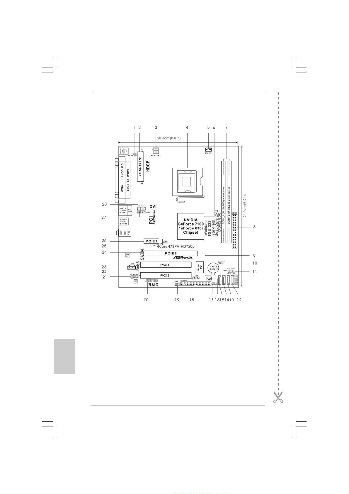
1 PS2_USB_PWR1 Jumper 16 Chassis Fan Connector (CHA_FAN1)
2 ATX Power Connector (ATXPWR1) 17 Chassis Speaker Header (SPEAKER 1)
3 ATX 12V Connector (ATX12V1) 18 Floppy Connector (FLOPPY1)
4 775-Pin CPU Socket 19 DeskExpress Hot Plug Detection Header
5 CPU Fan Connector (CPU_FAN1) (IR1)
6 North Bridge Controller 20 WiFi/E Header (WIFI/E)
7 2 x 240- pi n DD R2 DI MM Sl ot s 21 Front Panel Audio Header (HD_AUDIO1)
(DDRII_1 and DDRII_2; Yellow) 22 PCI Slots (PCI1 - 2)
8 IDE1 Connector (IDE1, Blue) 23 Internal Audio Connector: CD1 (Black)
9 Serial Port Connector (COM1) 24 PCI Express x16 Slot (PCIE2)
10 Clear CMOS Jumper (CLRCMOS1) 25 SPI Flash Memory (4Mb)
11 System Panel Header (PANEL1) 26 PCI Express x1 Slot (PCIE1)
12 Fourth SATAII Connector (SATAII_4 (PORT1.3)) 27 USB 2.0 Header (USB6_7, Blue)
13 Third SATAII Connector (SATAII_3 (PORT1.2)) 28 USB 2.0 Header (USB4_5, Blue)
14 Secondary SATAII Connector (SATAII_2 (PORT1.1))
15 Primary SATAII Connector (SATAII_1 (PORT1.0))
ASRock 4CoreN73PV-HD720p Motherboard
Page 3
ASRock 6CH_DVI I/OASRock 6CH_DVI I/O
ASRock 6CH_DVI I/O
ASRock 6CH_DVI I/OASRock 6CH_DVI I/O
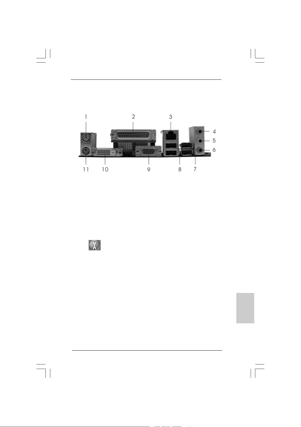
1 PS/2 Mouse Port (Green) 7 USB 2.0 Ports (USB23)
2 Parallel Port 8 USB 2.0 Ports (USB01)
3 RJ-45 Port 9 VGA/D-Sub Port
4 Line In (Light Blue) 10 VGA/DVI-D Port
5 Front Speaker (Lime) 11 PS/2 Keyboard Port (Purple)
* 6 Microphone (Pink)
* To enable Multi-Streaming function, you need to connect a front panel audio cable to the front
panel audio header. Please refer to below steps for the software setting of Multi-Streaming.
For Windows® XP:
After restarting your computer, you will find “Mixer” tool on your system. Please select “Mixer
ToolBox” , click “Enable playback multi-streaming”, and click “ok”. Choose “2CH” or
“4CH” and then you are allowed to select “Realtek HDA Primary output” to use Rear Speaker
and Front Speaker, or select “Realtek HDA Audio 2nd output” to use front panel audio. Then
reboot your system.
For Windows® VistaTM:
After restarting your computer, please double-click “Realtek HD Audio Manager” on the
system tray. Set “Speaker Configuration” to “Quadraphonic” or “Stereo”. Click “Device
advanced settings”, choose “Make front and rear output devices playbacks two different audio
streams simultaneously”, and click “ok”. Then reboot your system.
ASRock 4CoreN73PV-HD720p Motherboard
EnglishEnglish
EnglishEnglish
English
33
3
33
Page 4
1. Introduction1. Introduction
1. Introduction
1. Introduction1. Introduction
Thank you for purchasing ASRock 4CoreN73PV-HD720p motherboard, a reliable
motherboard produced under ASRock’s consistently stringent quality control. It delivers
excellent performance with robust design conf orming to ASRock’s commitment to quality and endurance.
This Quick Installation Guide contains introduction of the motherboard and step-bystep installation guide. More detailed information of the motherboard can be found in
the user manual presented in the Support CD.
Because the motherboard specifications and the BIOS software might be
updated, the content of this manual will be subject to change without
notice. In case any modifications of this manual occur, the updated
version will be available on ASRock website without further notice. You
may find the latest VGA cards and CPU support lists on ASRock website
as well. ASRock website http://www.asrock.com
If you require technical support related to this motherboard, please visit
our website for specific information about the model you are using.
www.asrock.com/support/index.asp
English
EnglishEnglish
EnglishEnglish
44
4
44
1.1 P1.1 P
1.1 P
1.1 P1.1 P
ASRock 4CoreN73PV-HD720p Motherboard
ASRock 4CoreN73PV-HD720p Quick In stallation Guide
ASRock 4CoreN73PV-HD720p Support CD
One 80-conductor Ultra A TA 66/100/133 IDE Ribbon Ca ble
One Ribbon Cable for a 3.5-in Floppy Drive
One Serial AT A (SATA) Data Ca ble (Optional)
One Serial AT A (SA TA) HDD Power Cable (Option al)
One ASRock 6CH DVI I/O Panel Shield
ackack
age Contentsage Contents
ack
age Contents
ackack
age Contentsage Contents
(Micro ATX Form Factor: 9.6-in x 8.0-in, 24.4 cm x 20.3 cm)
ASRock 4CoreN73PV-HD720p Motherboard
Page 5
1.21.2
SpecificationsSpecifications
1.2
Specifications
1.21.2
SpecificationsSpecifications
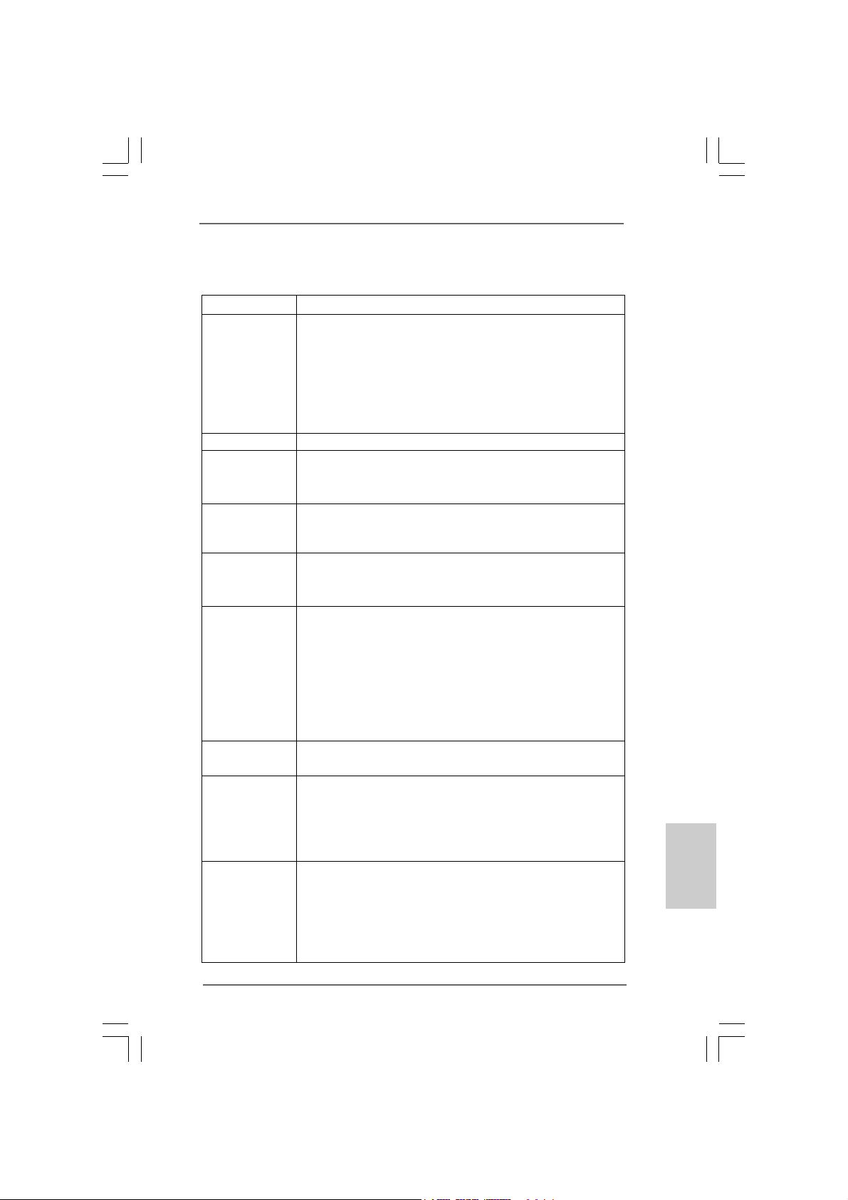
Platform - Micro ATX Form Factor: 9.6-in x 8.0-in, 24.4 cm x 20.3 cm
CPU - LGA 775 for Intel® CoreTM 2 Extreme / CoreTM 2 Quad / Core
2 Duo / Pentium® Dual Core / Celeron®, supporting Quad Core
Yorkfield and Dual Core Wolfdale processors
- FSB1333/1066/800/533MHz
- Supports Hyper-Threading Technology (see CAUTION 1)
- Supports Untied Overclocking Technology (see CAUTION 2)
- Supports EM64T CPU
Chipset - N VIDIA® GeForce 7100 / nForce 630i
Memory - 2 x DDR2 DIMM slots
- Support DDR2 800/667/533 non-ECC, un-buffered memory
- Max. capacity of system memory: 4GB (see CAUTION 3)
Hybrid Booster - CPU Frequency Stepless Control (see CAUTION 4)
- ASRock U-COP (see CAUTION 5)
- Boot Failure Guard (B.F.G.)
Expansion Slot - 1 x PCI Express x16 slot
- 1 x PCI Express x1 slot
- 2 x PCI slots
Graphics - Integrated NVIDIA® GeForce 7100
- DX9.0 VGA, Pixel Shader 3.0
- Max. shared memory 256MB (see CAUTION 6)
- Dual VGA Output: support DVI-D and D-Sub ports by
independent display controllers
- Supports HDCP function with DVI-D port
- Supports 720p Blu-ray (BD) / HD-DVD playback
(see CAUTION 7)
Audio - 5.1 CH Windows® VistaTM Premium Level HD Audio
(ALC662 Audio Codec)
LAN - 4CoreN73PV-HD720p R1.0:
Realtek Giga PHY RTL8211B, speed 10/100/1000 Mb/s
- 4CoreN73PV-HD720p R3.0:
Realtek PHY RTL8201CL, speed 10/100 Ethernet
- Supports Wake-On-LAN
Rear Panel I/O ASRock 6CH_DVI I/O
- 1 x PS/2 Mouse Port
- 1 x PS/2 Keyboard Port
- 1 x VGA/D-Sub Port
- 1 x VGA/DVI-D Port
- 1 x Parallel Port (ECP/EPP Support)
TM
EnglishEnglish
EnglishEnglish
English
ASRock 4CoreN73PV-HD720p Motherboard
55
5
55
Page 6
English
EnglishEnglish
EnglishEnglish
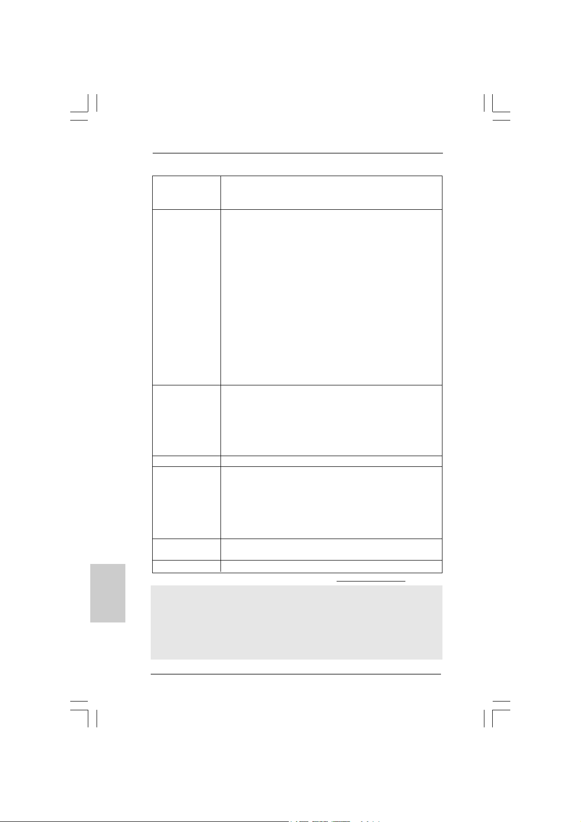
- 4 x Ready-to-Use USB 2.0 Ports
- 1 x RJ-45 Port
- HD Audio Jack: Line in/Front Spea ker/Microphone
Connector - 4 x Serial ATAII 3.0Gb/s connectors, support RAID (RAID 0,
RAID 1, RAID 0+1, JBOD and RAID 5), NCQ, AHCI and “Hot
Plug” functions (see CAUTION 8)
- 1 x ATA133 IDE connector (supports 2 x IDE devices)
- 1 x Floppy connector
- 1 x DeskExpress Hot Plug Detection header
- 1 x COM port header
- CPU/Chassis FAN connector
- 24 pin ATX power connector
- 4 pin 12V power connector
- CD in header
- Front panel audio connector
- 2 x USB 2.0 headers (support 4 USB 2.0 ports)
(see CAUTION 9)
- 1 x WiFi/E header (see CAUTION 10)
BIOS Feature - 4Mb AMI BIOS
- AMI Legal BIOS
- Supports “Plug and Play”
- ACPI 1.1 Compli ance Wake Up Events
- Supports jumperfree
- AMBIOS 2.3.1 Support
Support CD - Drivers, Utilities, AntiVirus Software (Trial Version)
Hardware - CPU Temperature Sensing
Monitor - Chassis Temperature Sensing
- CPU Fan Ta chometer
- Chassis Fan Tachometer
- CPU Quiet Fan
- Voltage Monitoring: +12V, +5V, +3.3V, CPU Vcore
OS - Microsoft® Windows® XP / XP 64-bit / Vista
TM
/ VistaTM 64-bit
compliant
Certifications - FCC, CE, WHQL
* For detailed product information, please visit our website: http://www.asrock.com
WARNING
Please realize that there is a certain risk involved with overclocking, including adjusting
the setting in the BIOS, applying Untied Overclocking Technology, or using the thirdparty overclocking tools. Overclocking may affect your system stability, or even
cause damage to the components and devices of your system. It should be done at
your own risk and expense. We are not responsible for possible damage caused by
overclocking.
66
6
66
ASRock 4CoreN73PV-HD720p Motherboard
Page 7
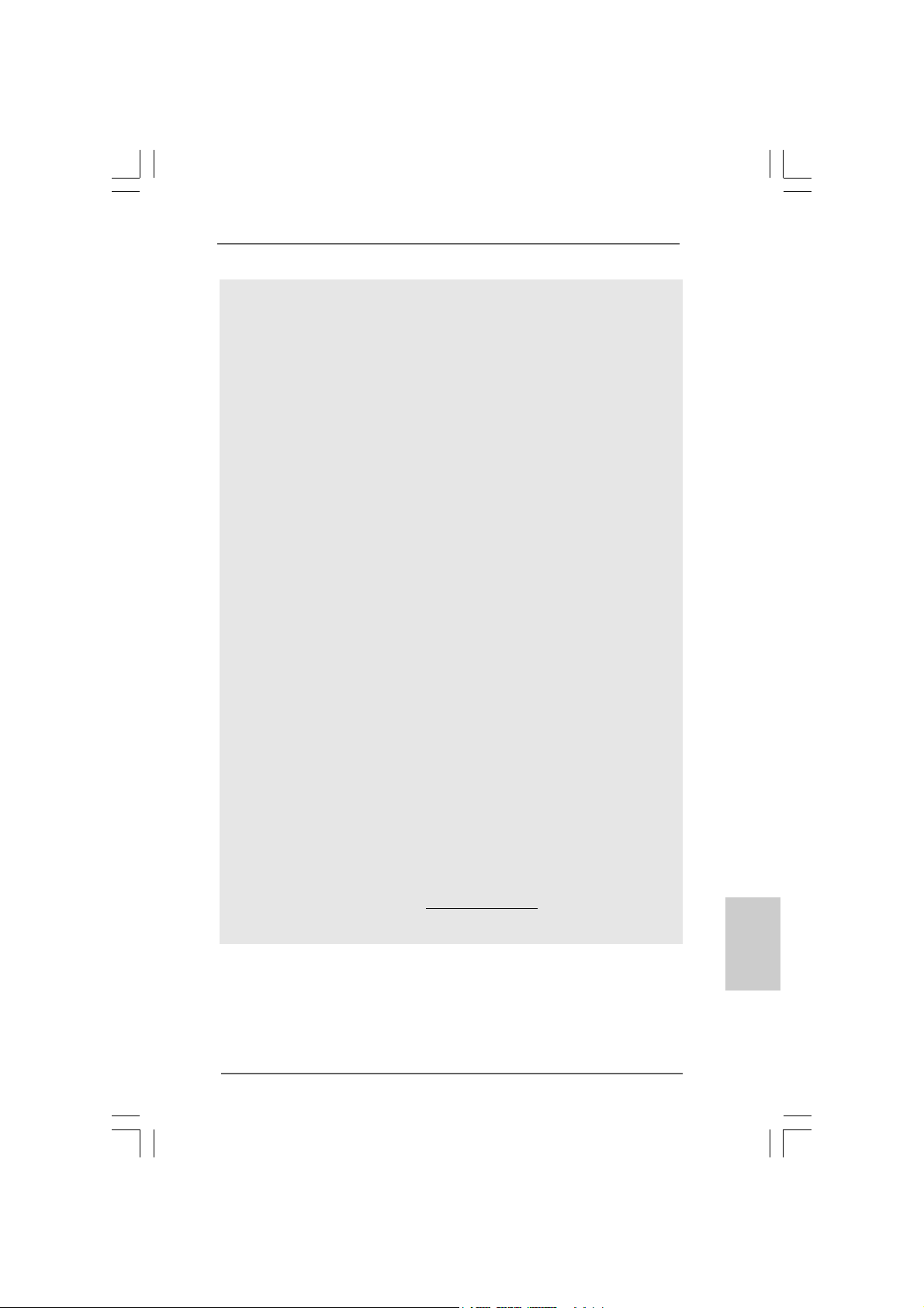
CAUTION!
1. About the setting of “Hyper Threading Technology”, please check page
40 of “User Manual“ in the support CD.
2. This motherboard supports Untied Overclocking Technology. Please read
“Untied Overclocking Technology” on page 30 for details.
3. Due to the operating system limitation, the actual memory size may be
less than 4GB for the reservation for system usage under Windows® XP
and Windows® VistaTM. For Windows® XP 64-bit and Windows® Vista
64-bit with 64-bit CPU, there is no such limitation.
4. Although this motherboard offers stepless control, it is not recommended
to perform over-clocking. Frequencies other than the recommended CPU
bus frequencies may cause the instability of the system or damage the
CPU.
5. While CPU overheat is detected, the system will automatically shutdown.
Before you resume the system, please check if the CPU fan on the
motherboard functions properly and unplug the power cord, then plug it
back again. To improve heat dissipation, remember to spray thermal grease
between the CPU and the heatsink when you install the PC system.
6. The maximum shared memory size is defined by the chipset vendor
and is subject to change. Please check NVIDIA® website for the latest
information.
7. 720p Blu-ray (BD) / HD-DVD playback support on this motherboard
requires the proper hardware configuration. Please refer to page 9 and 10
for the minimum hardware requirement and the passed 720p Blu-ray (BD)
/ HD-DVD films in our lab test.
8. Before installing SA TAII hard disk to SATAII connector, ple ase read the “SA TAII
Hard Disk Setup Guide” on page 24 to adjust your SATAII hard disk drive to
SATAII mode. You can also connect SATA hard disk to SATAII connector
directly.
9. Power Management for USB 2.0 works fine under Microsoft® Windows
VistaTM 64-bit / VistaTM / XP 64-bit / XP SP1 or SP2.
10. WiFi/E header supports WiFi+AP function with ASRock WiFi-802.11g or
WiFi-802.11n module, an easy-to-use wireless local area network
(WLAN) adapter. It allows you to create a wireless environment and
enjoy the convenience of wireless network connectivity. Please visit our
website for the availability of ASRock WiFi-802.11g or WiFi-802.11n
module. ASRock website http://www.asrock.com
TM
®
ASRock 4CoreN73PV-HD720p Motherboard
EnglishEnglish
EnglishEnglish
English
77
7
77
Page 8
1.31.3
Minimum Hardware RMinimum Hardware R
1.3
Minimum Hardware R
1.31.3
Minimum Hardware RMinimum Hardware R
® ®
®
WindowsWindows
Windows
WindowsWindows
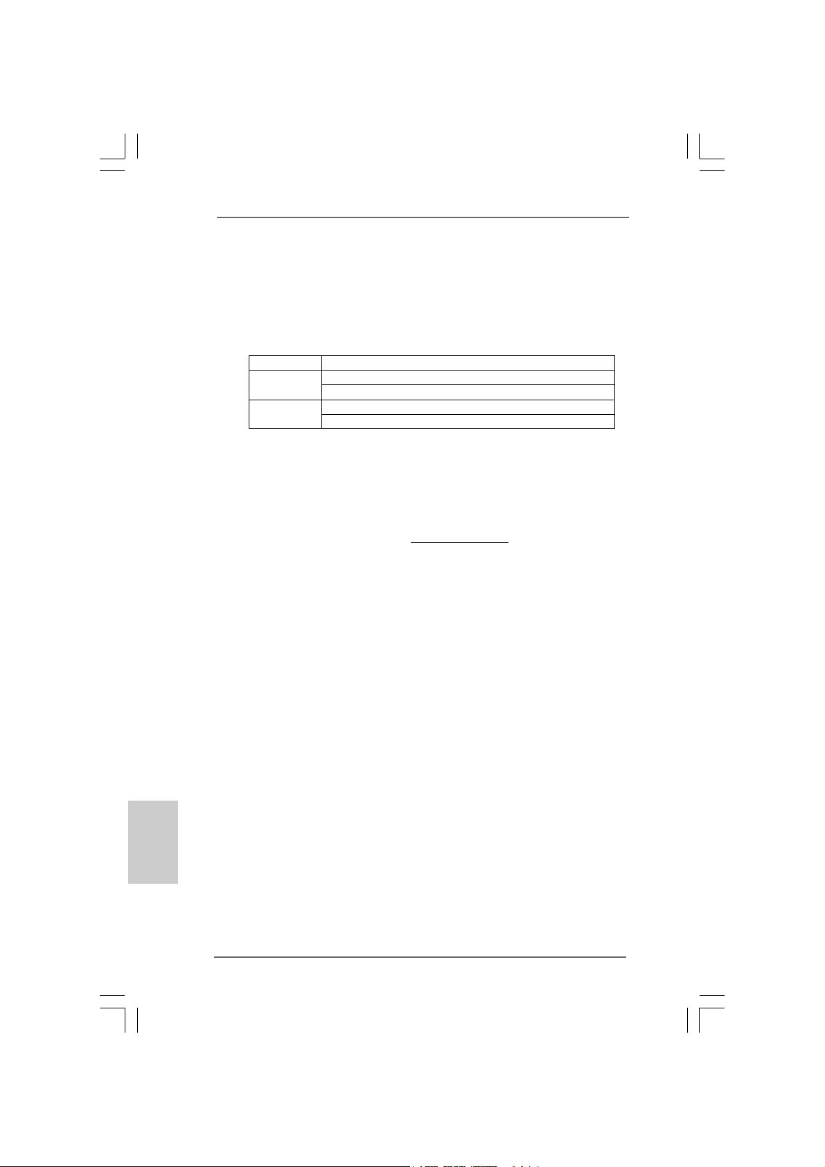
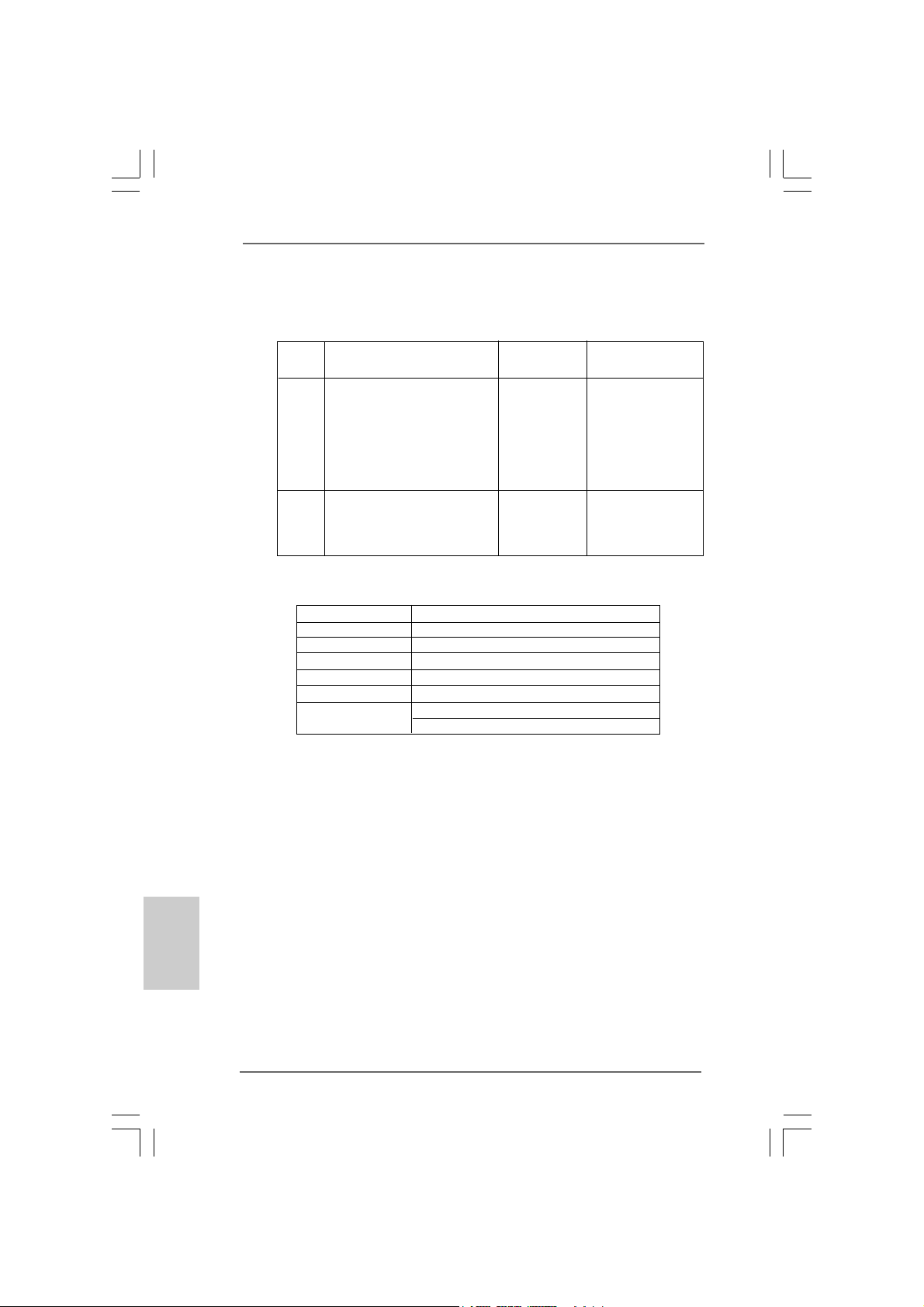
For system integrators and users who purchase this motherboard and
plan to submit Windows® VistaTM Premium 2007 and Basic logo, please follow
below table for minimum hardware requirements.
CPU Celeron D 326
Memory 1GB system memory (Premium)
VGA DX9.0 with WDDM Driver
* If you use onboard VGA with total system memory size 512MB and plan to
submit Windows® VistaTM Basic logo, please adjust the shared memory size of
onboard VGA to 64MB. If you use onboard VGA with total system memory size
above 512MB and plan to submit Windows® VistaTM Premium or Basic logo,
please adjust the shared memory size of onboard VGA to 128MB or above.
* If you plan to use external graphics card on this motherboard, please refer to
Premium Discrete requirement at http://www.asrock.com
* If the onboard VGA supports DVI, it must also support HDCP function to qualify for
Windows® VistaTM Premium 2007 logo.
* After June 1, 2007, all Windows® VistaTM systems are required to meet above
minimum hardware requirements in order to qualify for Windows® Vista
Premium 2007 logo.
® ®
TMTM
TM
TMTM
VistaVista
Vista
VistaVista
512MB Single Channel (Ba sic)
DVI with HDCP
equirement Tequirement T
equirement T
equirement Tequirement T
Premium 2007 and Basic Logo Premium 2007 and Basic Logo
Premium 2007 and Basic Logo
Premium 2007 and Basic Logo Premium 2007 and Basic Logo
able forable for
able for
able forable for
TM
English
EnglishEnglish
EnglishEnglish
88
8
88
ASRock 4CoreN73PV-HD720p Motherboard
Page 9
1.41.4
Minimum Hardware Requirement for 720p Blu-rayMinimum Hardware Requirement for 720p Blu-ray
1.4
Minimum Hardware Requirement for 720p Blu-ray
1.41.4
Minimum Hardware Requirement for 720p Blu-rayMinimum Hardware Requirement for 720p Blu-ray
(BD) / HD-DVD Playback Support(BD) / HD-DVD Playback Support
(BD) / HD-DVD Playback Support
(BD) / HD-DVD Playback Support(BD) / HD-DVD Playback Support
720p Blu-ray (BD) / HD-DVD playback support on this motherboard
requires the proper hardware configuration. Please refer to below table
for the minimum hardware requirement.
CPU Wolfdale E8500
VGA Onboard VGA with DVI-D port
Memory DDR2 800, 1GB x 2
Suggested OS Windows® VistaTM or Windows® VistaTM 64
* If you need to use CyberLink PowerDVD Ultra version 7.2 or 7.3, we suggest to
disable Hardware Acceleration function for better playback performance and
compatibility. After executing CyberLink PowerDVD Ultra program, please follow
below steps to disable Hardware Acceleration function.
A. Right-click the main page of CyberLink PowerDVD Ultra program.
B. Click “Configuration”.
C. Select “Video”.
D. Click “Enable hardware acceleration (nVidia PureVideo)” to remove the “V” mark
in this item.
E. Click “OK” to save the change.
ASRock 4CoreN73PV-HD720p Motherboard
EnglishEnglish
EnglishEnglish
English
99
9
99
Page 10
1.51.5
PP
1.5
1.51.5
assed 720p Blu-ray (BD) / HDassed 720p Blu-ray (BD) / HD
P
assed 720p Blu-ray (BD) / HD
PP
assed 720p Blu-ray (BD) / HDassed 720p Blu-ray (BD) / HD
LL
ab Tab T
estest
L
ab T
est
LL
ab Tab T
estest
DVD Film Name Format Producer
Type
Blu-ray SWORDFISH VC-1 WB
DVD UNDERWORLD EVOLUTION MPEG-2 SONY
CASINO ROYALE MPEG-4-AVC SONY
THE LAST STAND MPEG-4-AVC F OX
SPEED MPEG-4-AVC FOX
THE LEAGUE OF MPEG-4-AVC FOX
EXTRAORDINARY GENTLEMEN
HD- KING KONG VC-1 UNIVERSAL
DVD THE INTERPRETER MPEG-4-AVC UNIVERSAL
NEW ORLEANS CONCERT MPEG-2 WEA
ONE SIX RIGHT MPEG-2 TERWILLIGER
* MPEG-4-AVC mentioned above refers to the same format of H.264.
* Above passed films are tested under below configuration.
Items Configurations
CPU Wolfdale E8500
VG A Onboard V GA with DVI-D port
Memory DDR2 800, 1GB x 2
OS Windows® VistaTM or Windows® VistaTM 64
Playback Software CyberLink PowerDVD Ultra
DVD Player Pioneer BDR-101A / LG GBW-H10N (BD)
HP HD100 (HD-DVD)
-D-D
-D
-D-D
VD FVD F
VD F
VD FVD F
ilms in Ourilms in Our
ilms in Our
ilms in Ourilms in Our
English
EnglishEnglish
EnglishEnglish
1010
10
1010
ASRock 4CoreN73PV-HD720p Motherboard
Page 11
2.2.
InstallationInstallation
2.
Installation
2.2.
InstallationInstallation
Pre-installation PrecautionsPre-installation Precautions
Pre-installation Precautions
Pre-installation PrecautionsPre-installation Precautions
Take note of the following precautions before you install motherboard components or change any motherboard settings.
1. Unplug the power cord from the wall socket before touching any
component. Failure to do so may cause severe damage to the
motherboard, peripherals, and/or components.
2. To avoid damaging the motherboard components due to static
electricity, NEVER place your motherboard directly on the carpet
or the like. Also remember to use a grounded wrist strap or touch
a safety grounded object before you handle components.
3. Hold components by the edges and do not touch the ICs.
4. Whenever you uninstall any component, place it on a grounded
antstatic pad or in the bag that comes with the component.
5. When placing screws into the screw holes to secure the
motherboard to the chassis, please do not over-tighten the
screws! Doing so may damage the motherboard.
2.12.1
CPU InstallationCPU Installation
2.1
CPU Installation
2.12.1
CPU InstallationCPU Installation
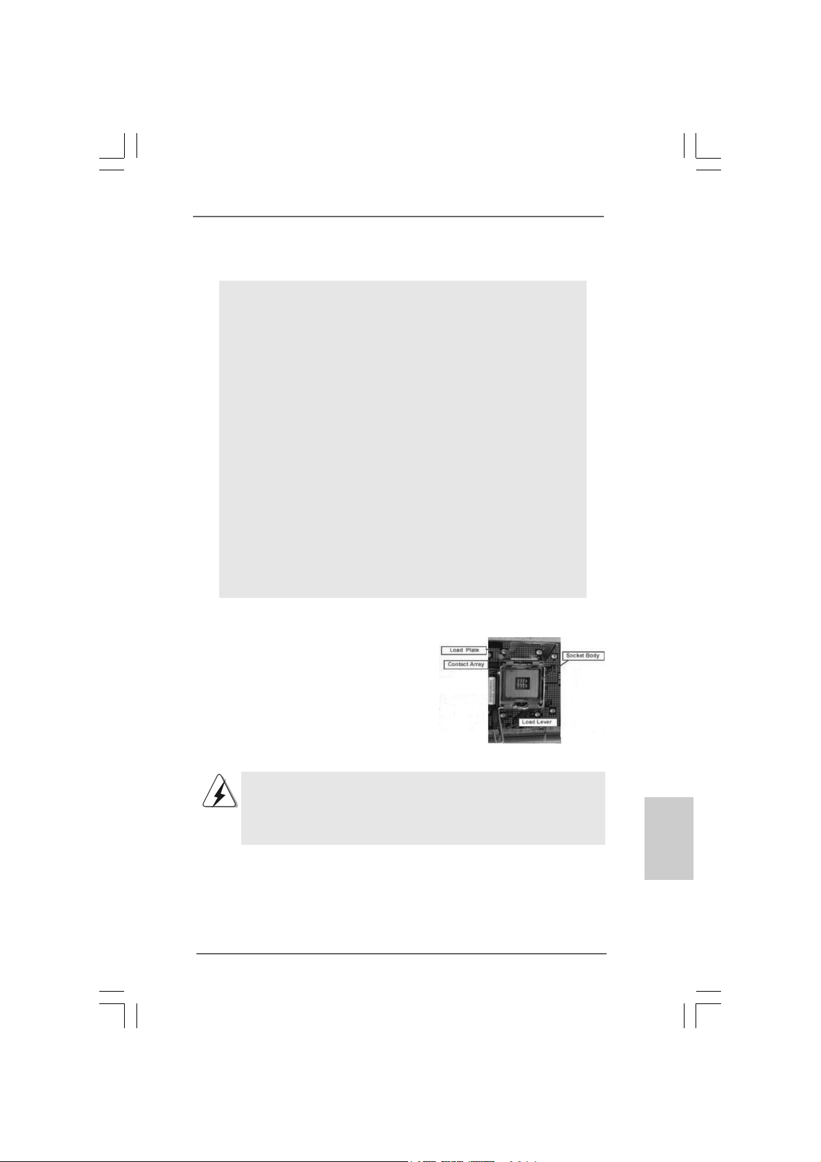
For the installation of Intel 775-LAND CPU,
please follow the steps below.
775-Pin Socket Overview
Before you insert the 775-LAND CPU into the socket, please check if
the CPU surface is unclean or if there is any bent pin on the socket.
Do not force to insert the CPU into the socket if above situation is
found. Otherwise, the CPU will be seriously damaged.
ASRock 4CoreN73PV-HD720p Motherboard
1111
11
1111
EnglishEnglish
EnglishEnglish
English
Page 12
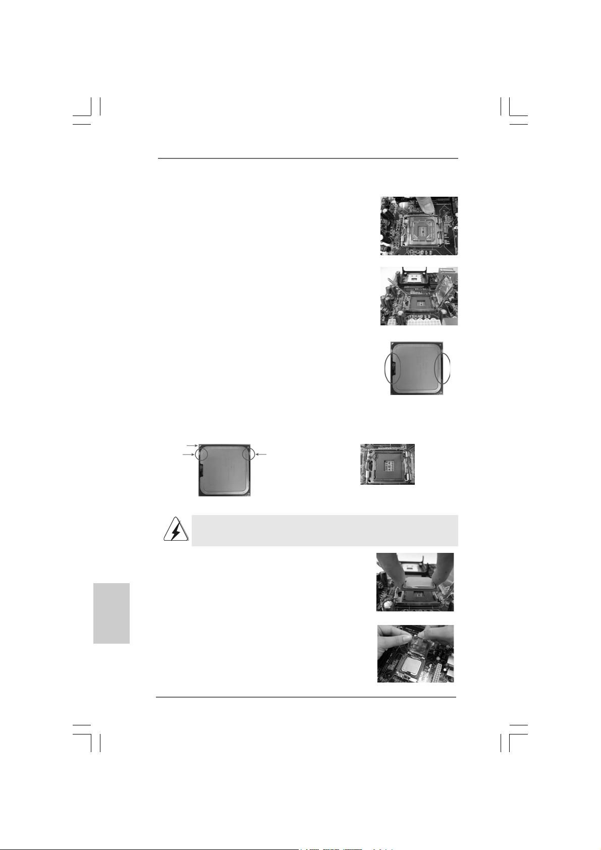
Step 1. Open the socket:
Step 1-1. Disengaging the lever by depressing
down and out on the hook to clear
retention tab.
Step 1-2. Rotate the load lever to fully open po-
sition at approximately 135 degrees.
Step 1-3. Rotate the load plate to fully open po-
sition at approximately 100 degrees.
Step 2. Insert the 775-LAND CPU:
Step 2-1. Hold the CPU by the edges where are
marked with black lines.
Step 2-2. Orient the CPU with IHS (Integrated
Heat Sink) up. Locate Pin1 and the two
orientation key notches.
Pin1
orientation
key notch
orientation
key notch
Pin1
alignment key
black line
black line
alignment key
English
EnglishEnglish
EnglishEnglish
1212
12
1212
775-Pin Socket
775-LAND CPU
For proper inserting, please ensure to match the two orientation key
notches of the CPU with the two alignment keys of the socket.
Step 2-3. Carefully pla ce the CPU into the socket
by using a purely vertical motion.
Step 2-4. Verify that the CPU is within the socket
and properly mated to the orient keys.
Step 3. Remove PnP Ca p (Pick a nd Place Cap):
Use your left hand index finger and thumb to
support the load plate edge, engage PnP cap
with right hand thumb and peel the cap from the
socket while pressing on center of PnP cap to
assist in removal.
ASRock 4CoreN73PV-HD720p Motherboard
Page 13
1. It is recommended to use the cap tab to handle and avoid kicking
off the PnP cap.
2. This cap must be placed if returning the motherboard for after
service.
Step 4. Close the socket:
Step 4-1. Rotate the load plate onto the IHS.
Step 4-2. While pressing down lightly on load
plate, engage the load lever.
Step 4-3. Secure load lever with load plate tab
under retention tab of load lever.
2.22.2
Installation of CPU Fan and HeatsinkInstallation of CPU Fan and Heatsink
2.2
Installation of CPU Fan and Heatsink
2.22.2
Installation of CPU Fan and HeatsinkInstallation of CPU Fan and Heatsink
For proper installation, please kindly refer to the instruction manuals of your CPU fan
and heatsink.
Below is an example to illustrate the installation of the heatsink for 775-LAND CPU.
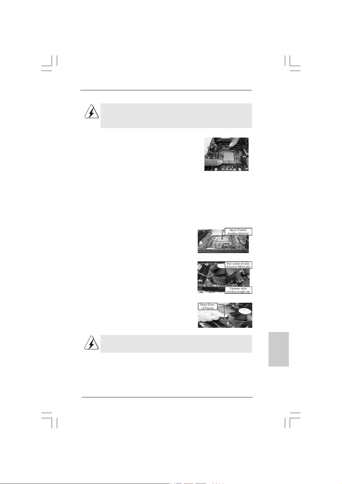
Step 1. Apply thermal interface material onto center
of IHS on the socket surface.
Step 2. Place the heatsink onto the socket. Ensure
fan cables are oriented on side closest to the
CPU fan connector on the motherboard
(CPU_FAN1, see page 2, No. 5).
Step 3. Align fasteners with the motherboard
throughholes.
Step 4. Rotate the fastener clockwise, then press
down on fastener caps with thumb to install
and lock. Repeat with remaining fasteners.
If you press down the fasteners without rotating them clockwise,
the heatsink cannot be secured on the motherboard.
Step 5. Connect fan header with the CPU fan
connector on the motherboard.
Step 6. Secure excess cable with tie-wrap to ensure
cable does not interfere with fan operation or
contact other components.
ASRock 4CoreN73PV-HD720p Motherboard
1313
13
1313
EnglishEnglish
EnglishEnglish
English
Page 14
2.3 Installation of Memor2.3 Installation of Memor
2.3 Installation of Memor
2.3 Installation of Memor2.3 Installation of Memor
This motherboard provides two 240-pin DDR2 (Double Data Rate 2) DIMM slots.
Please make sure to disconnect power supply before adding or
removing DIMMs or the system components.
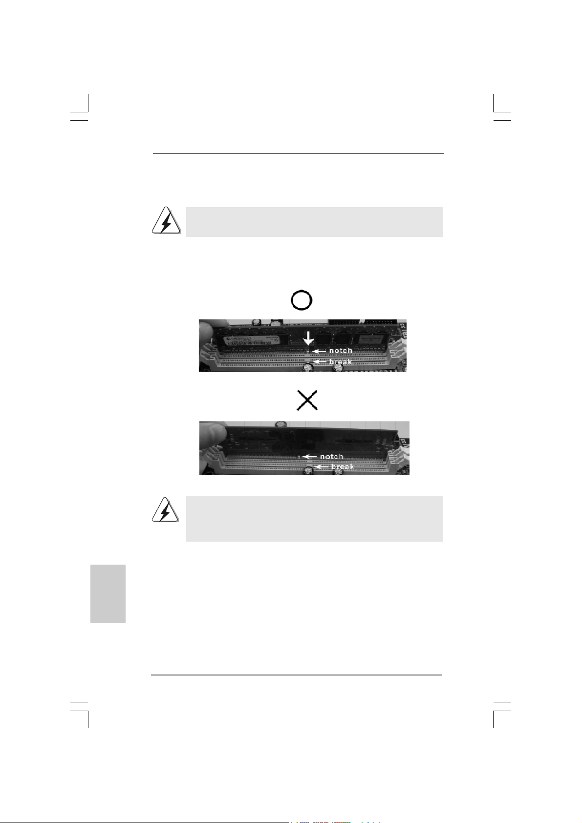
Step 1. Unlock a DIMM slot by pressing the retaining cli ps outward.
Step 2. Align a DIMM on the slot such that the notch on the DIMM matches the bre a k
on the slot.
y Modules (DIMM)y Modules (DIMM)
y Modules (DIMM)
y Modules (DIMM)y Modules (DIMM)
English
EnglishEnglish
EnglishEnglish
1414
14
1414
The DIMM only fits in one correct orientation. It will cause permanent
damage to the motherboard and the DIMM if you force the DIMM into the
slot at incorrect orientation.
Step 3. Firmly insert the DIMM into the slot until the retaining clips at both ends fully
sna p back in place and the DIMM is properly seated.
ASRock 4CoreN73PV-HD720p Motherboard
Page 15
2.4 Expansion Slots (PCI and PCI Express Slots)2.4 Expansion Slots (PCI and PCI Express Slots)
2.4 Expansion Slots (PCI and PCI Express Slots)
2.4 Expansion Slots (PCI and PCI Express Slots)2.4 Expansion Slots (PCI and PCI Express Slots)
There are 2 PCI slots and 2 PCI Express slots on this motherboard.
PCI slots: PCI slots are used to install expansion cards that have the 32-bit PCI
interface.
PCIE slots: PCIE1 (PCIE x1 slot) is used for PCI Express cards with x1 lane width
cards, such as Gigabit LAN card, SATA2 card, etc.
PCIE2 (PCIE x16 slot) is used for PCI Express cards with x16 lane
width graphics cards.
Installing an expansion cardInstalling an expansion card
Installing an expansion card
Installing an expansion cardInstalling an expansion card
Step 1. Before installing the expansion card, please make sure that the power supply
is switched off or the power cord is unplugged. Plea se read the documentation
of the expansion card a nd ma ke necessary hardware
settings for the card before you start the installation.
Step 2. Remove the bracket facing the slot that you intend to use. Keep the screws
for later use.
Step 3. Align the card connector with the slot and press firmly until the card is com-
pletely seated on the slot.
Step 4. Fasten the card to the chassis with screws.
ASRock 4CoreN73PV-HD720p Motherboard
1515
15
1515
EnglishEnglish
EnglishEnglish
English
Page 16
2.5 Dual Monitor and Surround Display Features2.5 Dual Monitor and Surround Display Features
2.5 Dual Monitor and Surround Display Features
2.5 Dual Monitor and Surround Display Features2.5 Dual Monitor and Surround Display Features
Dual Monitor Feature
This motherboard supports dual monitor feature. With the internal dual VGA output
support (DVI-D and D-Sub), you ca n easily enjoy the benefits of dual monitor feature
without installing any a dd-on VGA card to this motherboard. This motherboard also
provides independent display controllers for D VI-D a nd D-Sub to support dual V GA
output so that DVI-D a nd D-sub can drive same or different display contents. To enable
dual monitor feature, plea se follow the below ste ps:
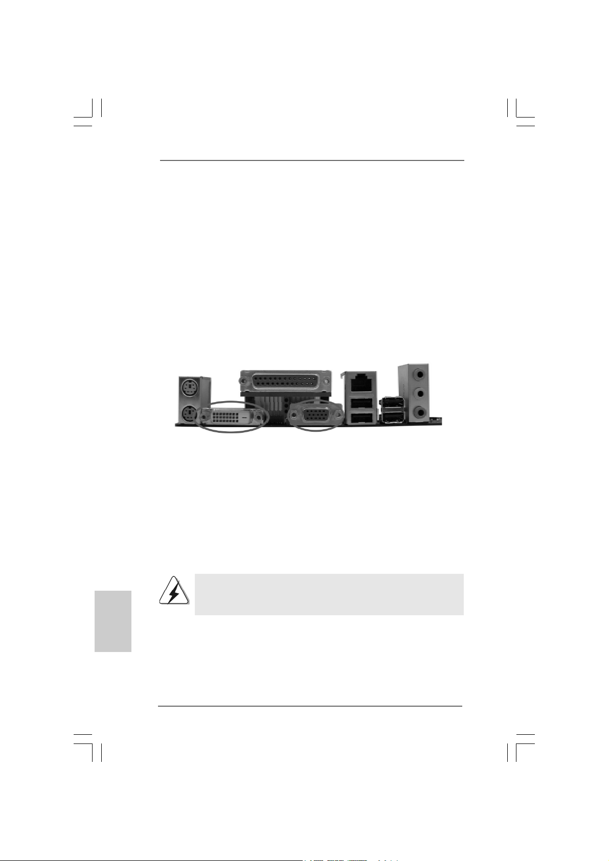
1. Connect the DVI-D monitor cable to the VGA/DVI-D port on the I/O panel of this
motherboard. Connect the D-Sub monitor cable to the VGA/D-Sub port on the I/O
panel of this motherboard.
English
EnglishEnglish
EnglishEnglish
1616
16
1616
VGA/DVI-D port
2. If you have installed onboard V GA driver from our support CD to your system
already , you can freely enjoy the benefits of dual monitor function provided by
V GA/DVI-D a nd VGA/D-Sub ports with this motherboard after your system
boots. If you haven’t installed onboard V GA driver yet, please in stall onboard
V GA driver from our support CD to your system a nd re start your computer.
Then you can start to use dual monitor function provided by VGA/DVI-D and
V GA/D-Sub ports with this motherboard.
When you playback HDCP-protected video from Blu-ray (BD) or
HD-DVD disc, the content will be displayed only in one of the two
monitors instead of both monitors.
ASRock 4CoreN73PV-HD720p Motherboard
VGA/D-Sub port
Page 17

Surround Display Feature
This motherboard supports surround display upgrade. With the internal dual VGA
output support (DVI-D and D-Sub) a nd the external a dd-on PCI Express VGA card, you
can easily enjoy the benefits of surround display feature. Plea se refer to the f ollowing
steps to set up a surround display environment:
1. Install the NVIDIA® PCI Express V GA card to PCIE2 slot. Please refer to page 15
for proper expansion card in stallation procedures f or details.
2. Connect the DVI-D monitor cable to the VGA/DVI-D port on the I/O panel of this
motherboard. Connect the D-Sub monitor cable to the VGA/D-Sub port on the I/O
panel of this motherboard.
3. Boot your system. Press <F2> to enter BIOS setup. Enter “Share Memory”
option to adjust the memory capability to [32MB], [64MB], [128MB] or [256MB] to
enable the function of VGA/D-sub. Please make sure that the value you select
is less than the total capability of the system memory. If you do not adjust the
BIOS setup, the default value of “Share Memory”, [Auto], will disable
V GA/D-Sub function when the a dd-on VGA card is inserted to this
motherboard.
4. Install the onboard V GA driver and the add-on PCI Express VGA card driver to
your system. If you have installed the onboard VGA driver a nd the add-on PCI
Express VGA card driver already, there is no need to install them again.
5. Set up a multi-monitor display.
For Windows® XP / XP 64-bit OS:
Right click the desktop, choose “Properties”, and select the “Settings” ta b so
that you can adjust the parameters of the multi-monitor according to the steps
below.
A. Click the “Identify” button to display a large number on each monitor.
B. Right-click the display icon in the Display Properties dialog that you wish
to be your primary monitor, and then select “Primary”. When you use
multiple monitors with your card, one monitor will always be Primary, and
all additional monitors will be designated as Secondary .
C. Select the display icon identified by the number 2.
D. Click “Extend my Windows desktop onto this monitor”.
E. Right-click the display icon and select “Attached”, if necessary.
F . Set the “Screen Re solution” a nd “Color Quality” as appropri ate f or the
second monitor. Click “Apply” or “OK” to apply these new values.
G. Repeat steps C through E for the di aplay icon identified by the number
one, two, three and four.
For Windows® VistaTM / VistaTM 64-bit OS:
Right click the desktop, choose “Personalize”, a nd sele ct the “Display
Settings” tab so that you can adjust the parameters of the multi-monitor
according to the steps below.
EnglishEnglish
EnglishEnglish
English
ASRock 4CoreN73PV-HD720p Motherboard
1717
17
1717
Page 18
A. Click the number ”2” icon.
B. Click the items “This is my main monitor” and “Extend the desktop onto
this monitor”.
C. Click “OK” to save your change.
D. Repeat steps A through C for the display icon identified by the number
three and four.
6. Use Surround Display. Click and drag the display icons to positions repre senting
the physical setup of your monitors that you would like to use. The placement of
display icons determines how you move items from one monitor to a nother.
HDCP Function with DVI-D Port
HDCP function is supported with DVI-D port on this motherboard. To
use HDCP function with this motherboard, you need to adopt the
monitor that supports HDCP function a s well. Theref ore, you ca n
enjoy the superior display quality with high-definition HDCP encryption
contents. Please refer to below in struction f or more details about HDCP
function.
What is HDCP?
HDCP stands f or High-Ba ndwidth Digital Content Protection, a
specification developed by Intel® for protecting digital entertainment
content that uses the DVI interface. HDCP is a copy prote ction
scheme to eliminate the possibility of intercepting digital data
midstream between the video source, or transmitter - such as a
computer, DVD player or set-top box - a nd the digital display, or
receiver - such as a monitor, television or projector. In other words,
HDCP specification is designed to protect the integrity of content as it
is being transmitted.
English
EnglishEnglish
EnglishEnglish
1818
18
1818
Products compatible with the HDCP scheme such a s DVD players,
satellite and cable HDTV set-top-boxes, as well a s few entertainment PCs requires a secure connection to a compliant display. Due
to the increase in manufacturers employing HDCP in their equi pment,
it is highly recommended that the HDTV or LCD monitor you purchase
is compatible.
ASRock 4CoreN73PV-HD720p Motherboard
Page 19
2.6 Jumpers Setup2.6 Jumpers Setup
2.6 Jumpers Setup
2.6 Jumpers Setup2.6 Jumpers Setup
The illustration shows how jumpers are
setup. When the jumper cap is placed on
pins, the jumper is “Short”. If no jumper cap
is placed on pins, the jumper is “Open”. The
illustration shows a 3-pin jumper whose pin1
and pin2 are “Short” when jumper cap is
placed on these 2 pins.
Jumper Setting Description
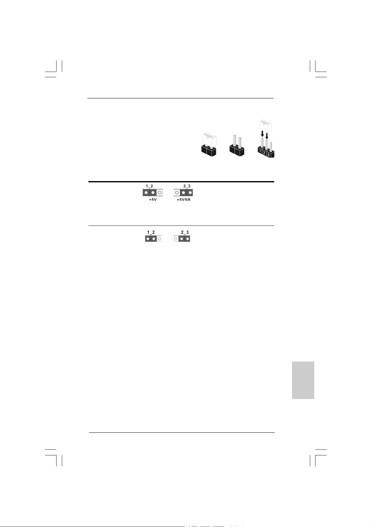
PS2_USB_PWR1 Short pin2, pin3 to enable
(see p.2 No. 1) +5VSB (standby) for PS/2
Note: To select +5VSB, it requires 2 Amp and higher sta ndby current provided by power
supply.
Clear CMOS Jumper
(CLRCMOS1)
(see p.2 No. 10)
Note: CLRCMOS1 allows you to clear the data in CMOS. The data in CMOS includes
system setup information such as system password, date, time, and system
setup parameters. To clear and reset the system parameters to default setup,
please turn of f the computer and unplug the power cord from the power supply.
After waiting for 15 seconds, use a jumper ca p to short pin2 and pin3 on CLRCMOS1
for 5 seconds. However , please do not clear the CMOS right after you update the
BIOS. If you need to clear the CMOS when you just finish updating the BIOS, you
must boot up the system first, and then shut it down before you do the clearCMOS action.
Clear CMOSDefault
Short Open
or USB wake up events.
ASRock 4CoreN73PV-HD720p Motherboard
1919
19
1919
EnglishEnglish
EnglishEnglish
English
Page 20
2.7 Onboard Headers and Connectors2.7 Onboard Headers and Connectors
2.7 Onboard Headers and Connectors
2.7 Onboard Headers and Connectors2.7 Onboard Headers and Connectors
Onboard headers and connectors are NOT jumpers. Do NOT place
jumper caps over these headers and connectors. Placing jumper
caps over the headers and connectors will cause permanent damage of the motherboard!
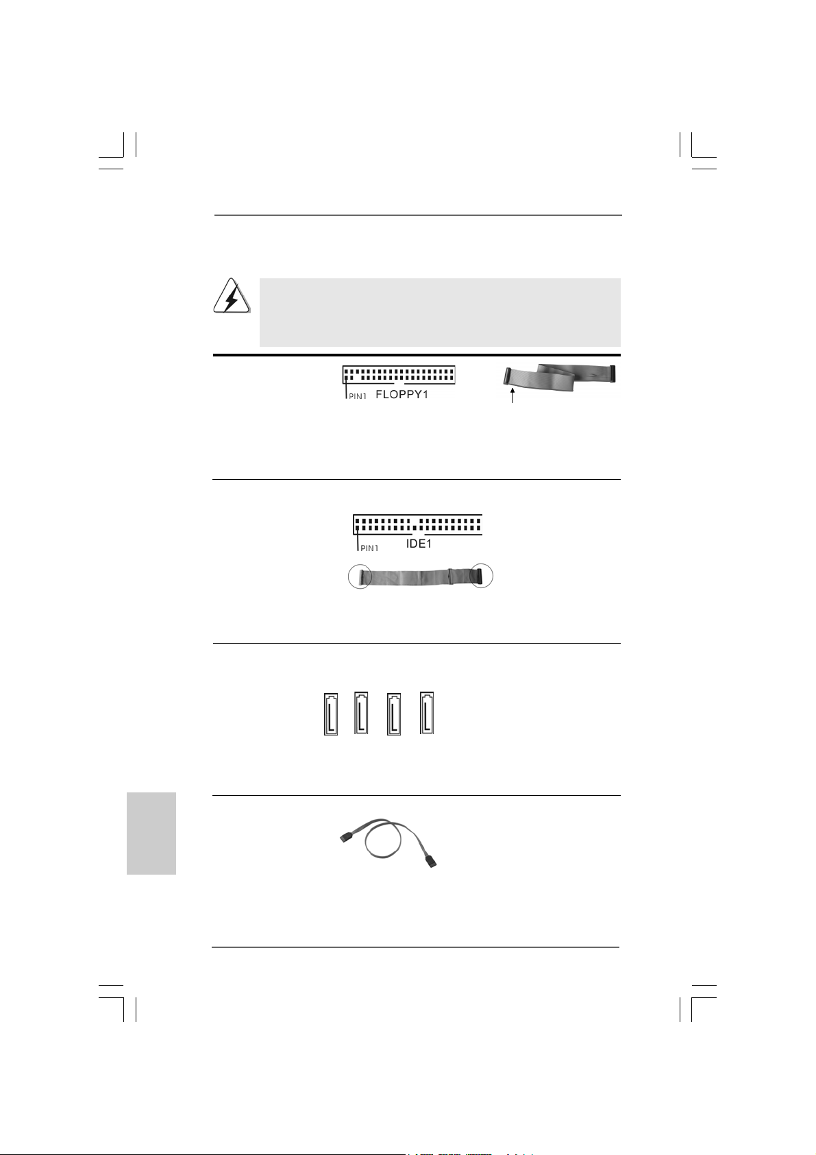
F DD conne ctor
(33-pin FLOPPY1)
(see p.2 No. 18)
the red-striped side to
Pin1
Note: Ma ke sure the red-striped side of the cable is plugged into Pin1 side of the
connector.
Primary IDE connector (Blue)
(39-pin IDE1, see p.2 No. 8)
English
EnglishEnglish
EnglishEnglish
2020
20
2020
connect the blue end
to the motherboard
connect the black end
to the IDE devices
80-conductor A T A 66/100133 ca ble
Note: Please refer to the instruction of your IDE device vendor for the details.
Serial A TAII Connectors These four Serial AT AII (SAT AII)
(SATAII_1 (PORT1.0): connectors support SATA data
see p.2, No. 15) cables for internal storage
(SATAII_2 (PORT1.1): devices. The current SA T AII
see p.2, No. 14) interface allows up to 3.0 Gb/s
(SATAII_3 (PORT1.2): data transfer rate.
see p.2, No. 13)
(SATAII_4 (PORT1.3):
see p.2, No. 12)
SATAII_1 (PORT1.0)
SATAII_2 (PORT1.1)
SATAII_3 (PORT1.2)
SATAII_4 (PORT1.3)
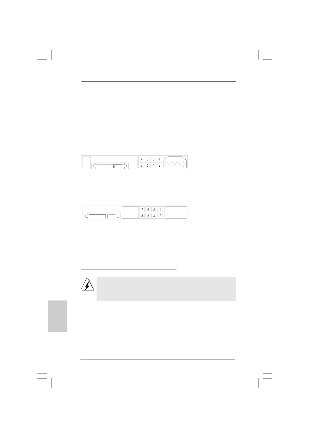
Serial ATA (SATA) Either end of the SAT A data cable
Data Cable can be connected to the SATA /
(Optional) SATAII hard disk or the SA TAII
connector on this motherboard.
ASRock 4CoreN73PV-HD720p Motherboard
Page 21
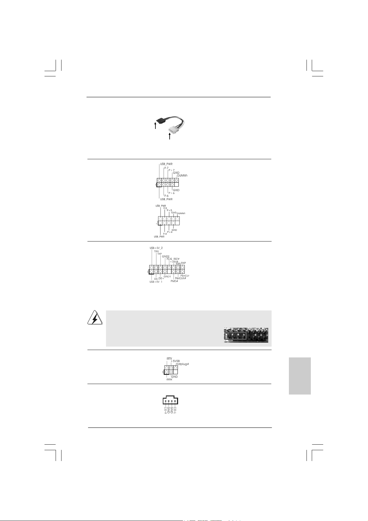
Serial ATA (SAT A) Please connect the black end of
Power Cable SAT A power ca ble to the power
(Optional) connector on each drive. Then
connect to the SATA
HDD power connector
connect to
the power
supply
connect the white end of SATA
power cable to the power
connector of the power supply.
USB 2.0 Headers Besides four default USB 2.0
(9-pin US6_7) ports on the I/O panel, there are
(see p.2 No. 27) two USB 2.0 headers on this
motherboard. Each USB 2.0
header can support two USB
2.0 ports.
(9-pin USB4_5)
(see p.2 No. 28)
WiFi/E Header This header supports WiFi+AP
(15-pin WIFI/E) function with ASRock
(see p.2 No. 20) WiFi-802.11g or WiFi-802.11n
module, an ea sy-to-use wirele ss
local area network (WLAN)
adapter. It allows you to create a
wireless environment and enjoy the
convenience of wireless network
connectivity.
If you don’t plan to use WiFi+AP functin on this motherboard, this header can be
used as a 4-Pin USB 2.0 header to support one USB 2.0 port. To connect the
4-Pin USB device cable to this header, please refer to
this picture for proper installation.
DeskExpress Hot Plug Dete ction This header supports the Hot
Header Plug detection function for
(5-pin IR1) ASRock DeskExpress.
(see p.2 No. 19)
Internal Audio Connectors This connector allows you
(4-pin CD1) to receive stereo audio input
(CD1: see p.2 No. 23) from sound sources such as
CD1
a CD-ROM, D VD-ROM, TV
tuner card, or MPEG card.
ASRock 4CoreN73PV-HD720p Motherboard
2121
21
2121
EnglishEnglish
EnglishEnglish
English
Page 22
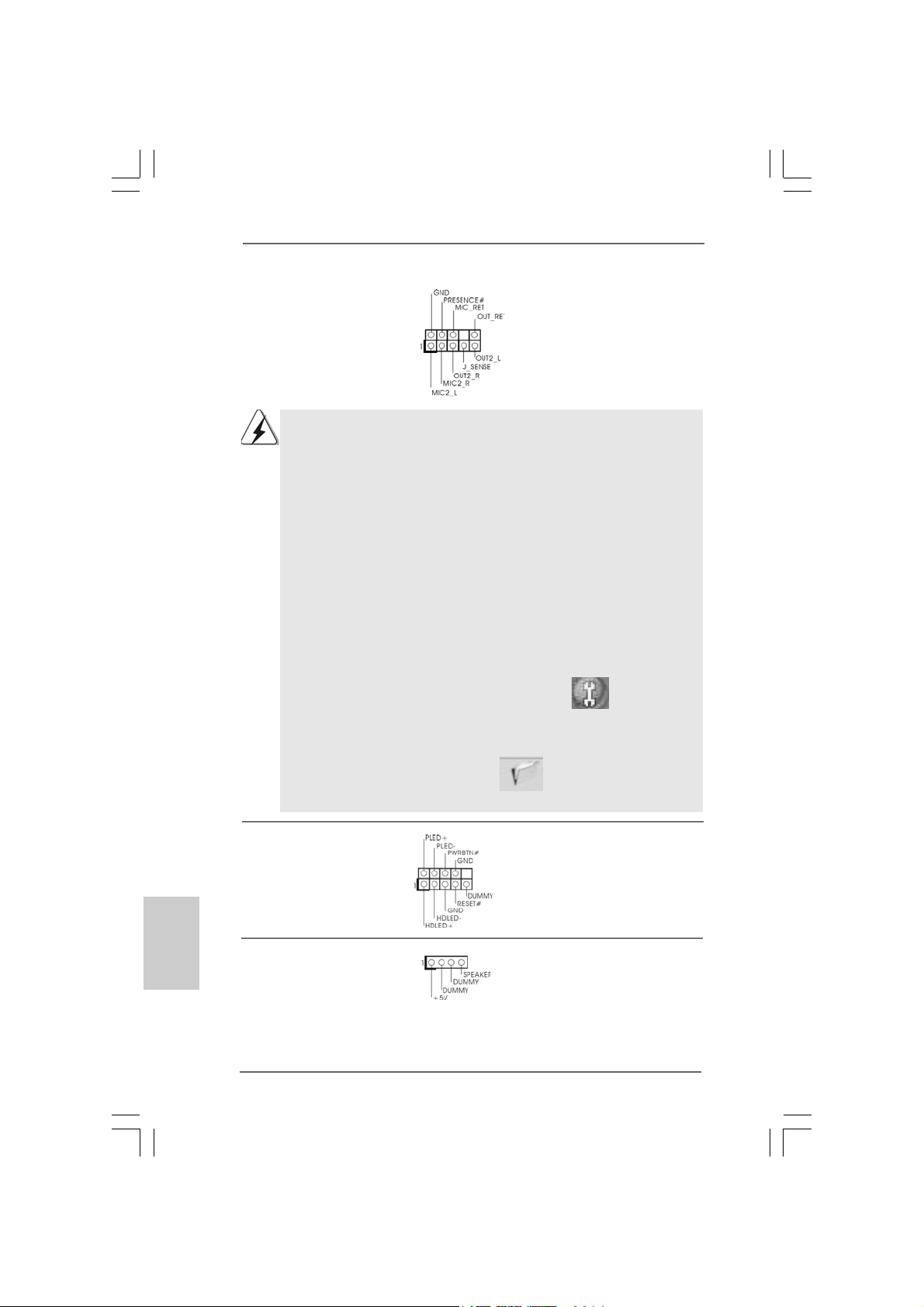
Front Panel Audio Header This is an interfa ce for front
(9-pin HD_AUDIO1) panel audio cable that allows
(see p.2 No. 21) convenient connection and
control of audio devices.
1. High Definition Audio supports Jack Sensing, but the panel wire on
the chassis must support HDA to function correctly. Please follow the
instruction in our manual and chassis manual to install your system.
2. If you use AC’97 audio panel, please install it to the front panel audio
header as below:
A. Connect Mic_IN (MIC) to MIC2_L.
B. Connect Audio_R (RIN) to OUT2_R and Audio_L (LIN) to OUT2_L.
C. Connect Ground (GND) to Ground (GND).
D. MIC_RET and OUT_RET are for HD audio panel only. You don’t
need to connect them for AC’97 audio panel.
E. Enter BIOS Setup Utility. Enter Advanced Settings, and then select
Chipset Configuration. Set the Front Panel Control option from
[Auto] to [Enabled].
F. Enter Windows system. Click the icon on the lower right hand
taskbar to enter Realtek HD Audio Manager.
For Windows
Click “Audio I/O”, select “Connector Settings” , choose
“Disable front panel jack detection”, and save the change by
clicking “OK”.
For Windows® VistaTM / VistaTM 64-bit OS:
Click the right-top “Folder” icon , choose “Disable front
®
XP / XP 64-bit OS:
English
EnglishEnglish
EnglishEnglish
2222
22
2222
panel jack detection”, and save the change by clicking “OK”.
System Panel Hea der This header a ccommodate s
(9-pin PANEL1) several system front panel
(see p.2 No. 11) functions.
Chassis Spea ker He ader Please connect the chassis
(4-pin SPEAKER 1) speaker to this hea der.
(see p.2 No. 17)
ASRock 4CoreN73PV-HD720p Motherboard
Page 23
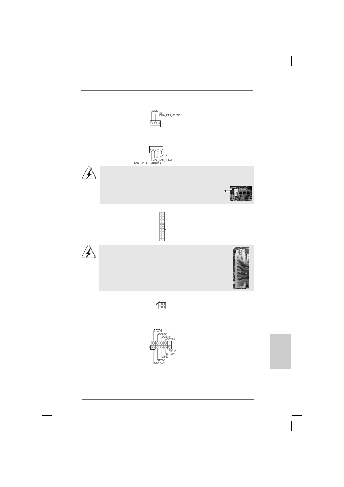
Chassis Fa n Connector Please connect a chassis fan
(3-pin CHA_FAN1) cable to this connector a n d
(see p.2 No. 16) match the black wire to the
ground pin.
CPU Fan Connector Please connect a CPU fan cable
(4-pin CPU_FAN1) to this connector and match
(see p.2 No. 5) the bla ck wire to the ground pin.
4 3 2 1
Though this motherboard provides 4-Pin CPU fan (Quiet Fan) support, the 3-Pin
CPU fan still can work successfully even without the fan speed control function.
If you plan to connect the 3-Pin CPU fan to the CPU fan connector on this
motherboard, please connect it to Pin 1-3.
24
ATX Power Conne ctor Please connect an A TX power
(24-pin ATXPWR1) supply to this connector.
(see p.2 No. 2)
12
13
1
Though this motherboard provides 24-pin ATX power connector,
Pin 1-3 Connected
3-Pin Fan Installation
12
it can still work if you adopt a traditional 20-pin ATX power supply.
To use the 20-pin ATX power supply, please plug your power
supply along with Pin 1 and Pin 13.
20-Pin ATX Power Supply Installation
1
ATX 12V Connector Please connect an A TX 12V
(4-pin ATX12V1) power supply to this connector.
(see p.2 No. 3)
24
13
Serial port Header This COM1 header
(9-pin COM1) supports a serial port module.
(see p.2 No. 9)
ASRock 4CoreN73PV-HD720p Motherboard
2323
23
2323
EnglishEnglish
EnglishEnglish
English
Page 24
2.8 SA2.8 SA
2.8 SA
2.8 SA2.8 SA
Before installing SATAII hard disk to your computer, please carefully rea d below
SATAII hard disk setup guide. Some default setting of SA TAII hard disks may not be
at SATAII mode, which operate with the best performa nce. In order to ena ble SATAII
function, please f ollow the below in struction with different vendors to corre ctly adjust
your SATAII hard disk to SA TAII mode in advance; otherwise, your SATAII hard dis k
may fail to run at SATAII mode.
Western Digital
If pin 5 and pin 6 are shorted, SATA 1.5Gb/s will be en abled.
On the other hand, if you wa nt to enable SAT AII 3.0Gb/s, please remove the jumpers
from pin 5 and pin 6.
SAMSUNG
If pin 3 and pin 4 are shorted, SATA 1.5Gb/s will be enabled.
On the other hand, if you want to enable SATAII 3.0Gb/s, please remove the
jumpers from pin 3 and pin 4.
TT
AII Hard Disk Setup GuideAII Hard Disk Setup Guide
T
AII Hard Disk Setup Guide
TT
AII Hard Disk Setup GuideAII Hard Disk Setup Guide
English
EnglishEnglish
EnglishEnglish
2424
24
2424
HITACHI
Please use the Feature Tool, a DOS-bootable tool, for changing various ATA
features. Please visit HITACHI’s website for details:
http://www.hitachigst.com/hdd/support/download.htm
The above examples are just for your reference. For different SATAII hard
disk products of different vendors, the jumper pin setting methods may not
be the same. Please visit the vendors’ website for the updates.
ASRock 4CoreN73PV-HD720p Motherboard
Page 25
2.9 Serial A2.9 Serial A
2.9 Serial A
2.9 Serial A2.9 Serial A
Installation Installation
Installation
Installation Installation
This motherboard adopts NVIDIA® GeForce 7100 / nForce 630i chipset that supports
Serial AT A (SAT A) / Seri al ATAII (SATAII) hard disks and RAID functions. Y ou may
install SA TA / SATAII hard disk s on this motherboard for intern al storage devices. This
section will guide you to install the SATA / SATAII hard disks.
STEP 1: Install the SATA / SATAII hard disk s into the drive bays of your chassis.
STEP 2: Connect the SATA power cable to the SAT A / SATAII hard disk.
STEP 3: Connect one end of the SATA data cable to the motherboard’s SATAII
STEP 4: Connect the other end of the SATA data cable to the SAT A / SATAII hard
2.102.10
Hot Plug and Hot Swap FHot Plug and Hot Swap F
2.10
Hot Plug and Hot Swap F
2.102.10
Hot Plug and Hot Swap FHot Plug and Hot Swap F
HDDsHDDs
HDDs
HDDsHDDs
This motherboard supports Hot Plug and Hot Swa p functions f or SA TA / SAT AII Devices
in RAID / AHCI mode. NVIDIA® GeForce 7100 / nForce 630i chipset provide s hardware
support for Advanced Host controller Interfa ce (AHCI), a new operation interface f or SA T A
host controllers developed thru a joint industry effort. AHCI also provides usability
enhancements such as Hot Plug.
TT
A (SAA (SA
TT
A (SA
A (SAA (SA
A) / Serial AA) / Serial A
T
A) / Serial A
TT
A) / Serial AA) / Serial A
T
TT
connector.
disk.
NOTE
What is Hot Plug Function?
If the SATA / SATAII HDDs are NOT set for RAID configuration, it is
called “Hot Plug” for the action to insert and remove the SATA / SATAII
HDDs while the system is still power-on and in working condition.
However, please note that it cannot perform Hot Plug if the OS has
been installed into the SATA / SATAII HDD.
TT
AII (SAAII (SA
T
AII (SA
TT
AII (SAAII (SA
unctions for SAunctions for SA
unctions for SA
unctions for SAunctions for SA
TT
AII) Hard DisksAII) Hard Disks
T
AII) Hard Disks
TT
AII) Hard DisksAII) Hard Disks
TT
A / SAA / SA
T
A / SA
TT
A / SAA / SA
TT
T
TT
AIIAII
AII
AIIAII
What is Hot Swap Function?
If SATA / SATAII HDDs are built as RAID 1 or RAID 5 then it is called
“Hot Swap” for the action to insert and remove the SATA / SATAII
HDDs while the system is still power-on and in working condition.
ASRock 4CoreN73PV-HD720p Motherboard
2525
25
2525
EnglishEnglish
EnglishEnglish
English
Page 26
2.112.11
Driver Installation GuideDriver Installation Guide
2.11
Driver Installation Guide
2.112.11
Driver Installation GuideDriver Installation Guide
To install the drivers to your system, plea se insert the support CD to your optical drive
first. Then, the drivers compatible to your system ca n be auto-detected and listed on
the support CD driver page. Please follow the order from up to bottom side to install
those required drivers. Therefore, the drivers you install can work properly.
English
EnglishEnglish
EnglishEnglish
2626
26
2626
2.122.12
Installing WindowsInstalling Windows
2.12
Installing Windows
2.122.12
Installing WindowsInstalling Windows
64-bit W64-bit W
64-bit W
64-bit W64-bit W
If you want to install Windows® XP, Windows® XP 64-bit, Windows® VistaTM or Windows
VistaTM 64-bit on your SATA / SATAII HDDs without RAID functions, please f ollow below
procedures according to the OS you install.
2.12.1 Installing Windows2.12.1 Installing Windows
2.12.1 Installing Windows
2.12.1 Installing Windows2.12.1 Installing Windows
F F
F
F F
If you want to install Windows® XP / Windows® XP 64-bit on your SA TA / SATAII HDDs
without RAID functions, please follow below steps.
Using SATA / SATAII HDDs with NCQ and Hot Plug functions
STEP 1: Set Up BIOS.
A. Enter BIOS SETUP UTILITY Advanced screen IDE Configuration.
B. Set the “SATA Operation Mode” option to [AHCI].
STEP 2: Make a SATA / SATAII driver diskette.
A. Insert the ASRock Support CD into your optical drive to boot your system.
(There are two ASRock Support CD in the motherboard gift box pack, please
choose the one for Windows® XP / XP 64-bit.)
B. During POST at the beginning of system boot-up, press <F11> key, and
then a window for boot devices selection appears. Please sele ct CD-ROM
as the boot device.
C. When you see the message on the screen, “Generate Seri al AT A driver
diskette [YN]?”, press <Y>.
D. Then you will see these messages,
Plea se choose:
1. Generate AHCI Driver diskette for WindowsXP
2. Generate RAID Driver diskette for WindowsXP
3. Generate AHCI Driver diskette for WindowsXP64
4. Generate RAID Driver diskette for WindowsXP64
5. Exit
Reboot system now
Press any key to continue
ithout RAID Fithout RAID F
ithout RAID F
ithout RAID Fithout RAID F
unctionsunctions
unctions
unctionsunctions
ASRock 4CoreN73PV-HD720p Motherboard
®
XP / XP 64-bit / Vista XP / XP 64-bit / Vista
XP / XP 64-bit / Vista
XP / XP 64-bit / Vista XP / XP 64-bit / Vista
unctionsunctions
unctions
unctionsunctions
®
XP / XP 64-bit Without RAID XP / XP 64-bit Without RAID
XP / XP 64-bit Without RAID
XP / XP 64-bit Without RAID XP / XP 64-bit Without RAID
TM TM
TM
TM TM
/ Vista/ Vista
/ Vista
/ Vista/ Vista
TMTM
TM
TMTM
®
Page 27
Plea se insert a floppy dis kette into the floppy drive. Select your required
item on the list according to the mode you choose and the OS you install.
Then press any key.
E. The system will start to format the floppy diskette and copy SATA / SATAII
drivers into the floppy diskette.
STEP 3: Install Windows® XP / XP 64-bit OS on your system.
After making a SATA / SAT AII driver dis kette, you ca n start to in stall Windows® XP / XP
64-bit on your system. At the beginning of Windows® setup, press F6 to install a thirdparty AHCI driver. When prompted, insert the SATA / SATAII driver dis kette containing
the NVIDIA® AHCI driver . After reading the floppy disk, the driver will be pre sented. Select
the driver to install according to the OS you install. The
drivers are as below:
A. NVIDIA nForce Storage Controller (required) Windows XP
B. NVIDIA nForce Storage Controller (required) Windows XP64
Please sele ct A f or Windows® XP in AHCI mode. Ple a se select B f or Windows® XP 64-bit
in AHCI mode.
Using SATA / SATAII HDDs without NCQ a nd Hot Plug function s
STEP 1: Set Up BIOS.
A. Enter BIOS SETUP UTILITY Advanced screen IDE Configuration.
B. Set the “SATA Operation Mode” option to [non-RAID].
STEP 2: Install Windows® XP / XP 64-bit OS on your system.
Vista Vista
Vista
Vista Vista
TMTM
TM
TMTM
/ Vista / Vista
/ Vista
/ Vista / Vista
2.12.2 Installing Windows2.12.2 Installing Windows
2.12.2 Installing Windows
2.12.2 Installing Windows2.12.2 Installing Windows
W W
ithout RAID Fithout RAID F
W
ithout RAID F
W W
ithout RAID Fithout RAID F
If you want to install Windows® VistaTM / Windows® VistaTM 64-bit on your SATA / SATAII
HDDs without RAID functions, please follow below steps.
Using SATA / SATAII HDDs with NCQ and Hot Plug functions
STEP 1: Set Up BIOS.
A. Enter BIOS SETUP UTILITY Advanced screen IDE Configuration.
B. Set the “SATA Operation Mode” option to [AHCI].
STEP 2: Install Windows® VistaTM / VistaTM 64-bit OS on your system.
Insert the Windows® VistaTM / Windows® VistaTM 64-bit optical disk into the optical drive
to boot your system, and follow the instruction to install Windows® VistaTM / Windows
VistaTM 64-bit OS on your system. When you see “Where do you want to install Windows?
” page, please insert the ASRock Support CD into your optical drive, and click the “Loa d
Driver” button on the left on the bottom to load the NVIDIA® AHCI drivers. NVIDIA® AHCI
drivers are in the following path in our Support CD:
ASRock 4CoreN73PV-HD720p Motherboard
®
unctionsunctions
unctions
unctionsunctions
TMTM
TM
TMTM
64-bit 64-bit
64-bit
64-bit 64-bit
EnglishEnglish
EnglishEnglish
®
2727
27
2727
English
Page 28
(There are two ASRock Support CD in the motherboard gift box pack, please
choose the one for Windows® VistaTM / VistaTM 64-bit.)
.. \ I386 \ AHCI_Vista (For Windows® Vista
.. \ AMD64\ AHCI_Vista64 (For Windows® Vista
After that, please insert Windows® VistaTM / Windows® VistaTM 64-bit optical disk into
the optical drive again to continue the installation.
Using SATA / SATAII HDDs without NCQ a nd Hot Plug function s
STEP 1: Set Up BIOS.
A. Enter BIOS SETUP UTILITY Advanced screen IDE Configuration.
B. Set the “SATA Operation Mode” option to [non-RAID].
STEP 2: Install Windows® VistaTM / VistaTM 64-bit OS on your system.
Insert the Windows® VistaTM / Windows® VistaTM 64-bit optical disk into the optical drive
to boot your system, and follow the instruction to install Windows® VistaTM / Windows
VistaTM 64-bit OS on your system.
TM
OS)
TM
64-bit OS)
®
English
EnglishEnglish
EnglishEnglish
2.132.13
Installing WindowsInstalling Windows
2.13
Installing Windows
2.132.13
Installing WindowsInstalling Windows
64-bit W64-bit W
64-bit W
64-bit W64-bit W
If you want to install Windows® XP, Windows® XP 64-bit, Windows® VistaTM or Windows
VistaTM 64-bit on your SATA / SATAII HDDs with RAID functions, please follow below
procedures according to the OS you install.
2.13.1 Installing Windows2.13.1 Installing Windows
2.13.1 Installing Windows
2.13.1 Installing Windows2.13.1 Installing Windows
F F
F
F F
If you want to install Windows® XP / Windows® XP 64-bit on your SA TA / SATAII HDDs
with RAID functions, please follow below steps.
STEP 1: Set Up BIOS.
A. Enter BIOS SETUP UTILITY Advanced screen IDE Configuration.
B. Set the “SATA Operation Mode” option to [RAID].
STEP 2: Make a SATA / SATAII driver diskette.
Please make a SATA / SATAII driver diskette by f ollowing se ction 2.12.1 step 2 on
page 26.
STEP 3: Use “RAID Installation Guide” to set RAID configuration.
Before you start to configure RAID function, you need to check the RAID installation
guide in the Support CD f or proper configuration. Please refer to the BIOS RAID
installation guide part of the document in the following path in the Support CD:
.. \ RAID Installation Guide
ith RAID Fith RAID F
ith RAID F
ith RAID Fith RAID F
unctionsunctions
unctions
unctionsunctions
®
XP / XP 64-bit / Vista XP / XP 64-bit / Vista
XP / XP 64-bit / Vista
XP / XP 64-bit / Vista XP / XP 64-bit / Vista
unctionsunctions
unctions
unctionsunctions
®
XP / XP 64-bit With RAID XP / XP 64-bit With RAID
XP / XP 64-bit With RAID
XP / XP 64-bit With RAID XP / XP 64-bit With RAID
TM TM
TM
TM TM
/ Vista/ Vista
/ Vista
/ Vista/ Vista
TMTM
TM
TMTM
®
2828
28
2828
ASRock 4CoreN73PV-HD720p Motherboard
Page 29
STEP 4: Install Windows® XP / XP 64-bit OS on your system.
After step1, 2, 3, you can start to install Windows® XP / Windows® XP 64-bit OS on your
system. At the beginning of Windows® setup, press F6 to install a third-party RAID
driver. When prompted, in sert the SATA / SATAII driver diskette containing the NVIDIA
RAID driver . After reading the floppy dis k, the drivers will be presented. Select the drivers
to install. The drivers are as below:
A. NVIDIA RAID Driver (required)
B. NVIDIA nForce Storage Controller (required)
Please select A a nd B f or Windows® XP / XP 64-bit in RAID mode. (There are two RAID
drivers needed for RAID mode, you have to sele ct them se parately. Plea se specify the
first RAID driver a nd then specify again f or the second one.)
NOTE. If you install Windows® XP / Windows® XP 64-bit on IDE HDDs and want to manage
(create, convert, delete, or rebuild) RAID functions on SATA / SATAII HDDs, you still
need to set up “SATA Operation Mode” to [RAID] in BIOS first. Then, please set the
RAID configuration by using the Windows RAID installation guide part of the docu
ment in the following path in the Support CD:
.. \ RAID Installation Guide
®
Vista Vista
Vista
Vista Vista
TM
OS)
TMTM
TM
TMTM
/ Vista / Vista
/ Vista
/ Vista / Vista
TM
64-bit OS)
2.13.2 Installing Windows2.13.2 Installing Windows
2.13.2 Installing Windows
2.13.2 Installing Windows2.13.2 Installing Windows
RAID F RAID F
RAID F
RAID F RAID F
If you want to install Windows® VistaTM / Windows® VistaTM 64-bit on your SATA / SATAII
HDDs with RAID functions, please follow below steps.
STEP 1: Set Up BIOS.
A. Enter BIOS SETUP UTILITY Advanced screen IDE Configuration.
B. Set the “SATA Operation Mode” option to [RAID].
STEP 2: Use “RAID Installation Guide” to set RAID configuration.
Before you start to configure RAID function, you need to check the RAID installation
guide in the Support CD f or proper configuration. Please refer to the BIOS RAID
installation guide part of the document in the following path in the Support CD:
.. \ RAID Installation Guide
STEP 3: Install Windows® VistaTM / VistaTM 64-bit OS on your system.
Insert the Windows® VistaTM / Windows® VistaTM 64-bit optical disk into the optical drive
to boot your system, and follow the instruction to install Windows® VistaTM / Windows
VistaTM 64-bit OS on your system. When you see “Where do you want to install Windows?
” page, please in sert the ASRock Support CD into your optical drive,
and click the “Load Driver” button on the left on the bottom to load the NVIDIA® RAID
drivers. NVIDIA® RAID drivers are in the following path in our Support CD:
(There are two ASRock Support CD in the motherboard gift box pack, please
choose the one for Windows® VistaTM / VistaTM 64-bit.)
.. \ I386 \ RAID_Vista (For Windows® Vista
.. \ AMD64\ RAID_Vista64 (For Windows® Vista
unctionsunctions
unctions
unctionsunctions
ASRock 4CoreN73PV-HD720p Motherboard
®
TMTM
TM
TMTM
64-bit With 64-bit With
64-bit With
64-bit With 64-bit With
®
EnglishEnglish
EnglishEnglish
English
2929
29
2929
Page 30
After that, please insert Windows® VistaTM / Windows® VistaTM 64-bit optical disk into
the optical drive again to continue the installation.
NOTE. If you install Windows® VistaTM / Windows® VistaTM 64-bit on IDE HDDs and want to
manage (create, convert, delete, or rebuild) RAID functions on SATA / SATAII HDDs,
you still need to set up “SATA Operation Mode” to [RAID] in BIOS first. Then, please
set the RAID configuration by using the Windows RAID installation guide in the
following path in the Support CD:
.. \ RAID Installation Guide
2.142.14
Untied Overclocking TUntied Overclocking T
2.14
Untied Overclocking T
2.142.14
Untied Overclocking TUntied Overclocking T
This motherboard supports Untied Overclocking Technology, which means during
overclocking, FSB enjoys better margin due to fixed PCI / PCIE buses. Before you
enable Untied Overclocking function, ple ase enter “Overclock Mode” option of BIOS setup
to set the selection from [Auto] to [CPU, PCIE, Async.]. Theref ore, CPU FSB is untied
during overclocking, but PCI / PCIE buses are in the fixed mode so that FSB can operate
under a more stable overclocking environment.
Please refer to the warning on page 6 for the possible overclocking risk
before you apply Untied Overclocking Technology.
3. BIOS Information3. BIOS Information
3. BIOS Information
3. BIOS Information3. BIOS Information
The Flash Memory on the motherboard stores BIOS Setup Utility. When you start up
the computer, please press <F2> during the Power-On-Self-Test (POST) to enter
BIOS Setup utility; otherwise, POST continues with its test routines. If you wish to
enter BIOS Setup after POST, please restart the system by pressing <Ctl> + <Alt> +
<Delete>, or pressing the reset button on the system chassis. The BIOS Setup
program is designed to be user-friendly. It is a menu-driven program, which allows
you to scroll through its various sub-menus and to select among the predetermined
choices. For the detailed information about BIOS Setup, please refer to the User
Manual (PDF file) contained in the Support CD.
echnologyechnology
echnology
echnologyechnology
English
EnglishEnglish
EnglishEnglish
3030
30
3030
4. Software Support CD information
This motherboard supports various Microsoft® Windows® operating systems: XP /
XP 64-bit / VistaTM / Vista
contains necessary drivers and useful utilities that will enhance motherboard features.
To begin using the Support CD, insert the CD into your CD-ROM drive. It will display
the Main Menu automatically if “AUTORUN” is enabled in your computer. If the Main
Menu does not appear automatically, locate and double-click on the file “ASSETUP.
EXE” from the BIN folder in the Support CD to display the menus.
TM
64-bit. The Support CD that came with the motherboard
ASRock 4CoreN73PV-HD720p Motherboard
Page 31

1. Einführung1. Einführung
1. Einführung
1. Einführung1. Einführung
Wir danken Ihnen für den Kauf des ASRock 4CoreN73PV-HD720p Motherboard,
ein zuverlässiges Produkt, welches unter den ständigen, strengen Qualitätskontrollen
von ASRock gefertigt wurde. Es bietet Ihnen exzellente Leistung und robuste s Design,
gemäß der Verpflichtung von ASRock zu Qualität und Halbarkeit.
Diese Schnellinstallationsanleitung führt in das Motherboard und die schrittweise
Installation ein. Details über das Motherboard finden Sie in der
Bedienungsanleitung auf der Support-CD.
Da sich Motherboard-Spezifikationen und BIOS-Software verändern können,
kann der Inhalt dieses Handbuches ebenfalls jederzeit geändert werden. Für
den Fall, dass sich Änderungen an diesem Handbuch ergeben, wird eine neue
Version auf der ASRock-Website, ohne weitere Ankündigung, verfügbar sein.
Die neuesten Grafikkarten und unterstützten CPUs sind auch auf der
ASRock-Website aufgelistet.
ASRock-Website: http://www.asrock.com
Wenn Sie technische Unterstützung zu Ihrem Motherboard oder spezifische
Informationen zu Ihrem Modell benötigen, besuchen Sie bitte unsere
Webseite:
www.asrock.com/support/index.asp
1.1 Kartoninhalt
ASRock 4CoreN73PV-HD720p Motherboard
(Micro ATX-Formfaktor: 24.4 cm x 20.3 cm; 9.6 Zoll x 8.0 Zoll)
ASRock 4CoreN73PV-HD720p Schnellinstallationsanleitung
ASRock 4CoreN73PV-HD720p Support-CD
Ein 80-adriges Ultra-ATA 66/100/133 IDE-Flachbandkabel
Ein Flachbandkabel für ein 3,5-Zoll-Diskettenlaufwerk
Ein Serial ATA (SATA) -Datenkabel (optional)
Ein Serial ATA (SATA) -Festplattenstromkabel (optional)
Ein ASRock 6CH DVI I/O Shield
ASRock 4CoreN73PV-HD720p Motherboard
3131
31
3131
DeutschDeutsch
DeutschDeutsch
Deutsch
Page 32

1.21.2
SpezifikationenSpezifikationen
1.2
Spezifikationen
1.21.2
SpezifikationenSpezifikationen
Deutsch
DeutschDeutsch
DeutschDeutsch
Plattform - Micro ATX-Formfaktor: 24.4 cm x 20.3 cm; 9.6 Zoll x 8.0 Zoll
CPU - LGA 775 für Intel® CoreTM 2 Extreme / CoreTM 2 Quad / Core
2 Duo / Pentium® Dual Core / Celeron® unterstützt Quad Core
Yorkfield und Dual Core Wolfdale Prozessoren
- FSB1333/1066/800/533MHz
- Unterstützt Hyper-Threading-Technologie
(siehe VORSICHT 1)
- Unterstützt Untied-Übertaktungstechnologie
(siehe VORSICHT 2)
- Unterstützt EM64T -CPU
Chipsatz - NVIDIA® GeForce 7100 / nForce 630i
Speicher - 2 x Steckplätze für DDR2
- Unterstützt DDR2 800/667/533 non-ECC, ungepufferter
Speicher
- Max. Kapazität des Systemspeichers: 4GB
(siehe VORSICHT 3)
Hybrid Booster - Schrittloser CPU-Frequenz-Kontrolle (siehe VORSICHT 4)
- ASRock U-COP (siehe VORSICHT 5)
- Boot Failure Guard (B.F.G. – Systemstartfehlerschutz)
Erweiterungs- - 1 x PCI Express x16-Steckplätze
steckplätze - 1 x PCI Express x1-Steckplätze
- 2 x PCI -Steckplätze
Onboard-VGA - Integrierte NVIDIA® GeForce7100
- DX9.0 VGA, Pixel Shader 3.0
- Maximal gemeinsam genutzter Speicher 256 MB
(siehe VORSICHT 6)
- Doppel-VGA Ausgabe: unterstützt D VI-D und D-Sub Ports
durch unabhängige Bildschirmanzeige Kontrolleure
- unterstützt HDCP Funktion mit DVI-D Port
- unterstützt 720p Blu-ray (BD) / HD-DVD Playback
(siehe VORSICHT 7)
Audio - 5.1 CH Windows® VistaTM Premium Level HD Audio
(ALC662 Audio Codec)
LAN - 4CoreN73PV-HD720p R1.0
Realtek Giga PHY RTL8211B, speed 10/100/1000 Mb/s
- 4CoreN73PV-HD720p R3.0
Realtek PHY RTL8201CL, speed 10/100 Mb/s
- Unterstützt Wake-On-LAN
TM
3232
32
3232
ASRock 4CoreN73PV-HD720p Motherboard
Page 33

E/A-Anschlüsse ASRock 6CH_D VI I/O
an der - 1 x PS/2-Mausanschluss
Rückseite - 1 x PS/2-Tastaturanschluss
- 1 x VGA/D-Sub port
- 1 x VGA/DVI-D port
- 1 x Paralleler port: Unterstützung für ECP / EPP
- 4 x Standard-USB 2.0-Anschlüsse
- 1 x RJ-45 port
- HD Audiobuchse: Audioeingang / Lautsprecher vorne /
Mikrofon
Anschlüsse - 4 x SATAII-Anschlüsse, unterstützt bis 3.0 Gb/s
Datenübertragungsrate, unterstützt RAID (RAID 0, RAID 1,
RAID 0+1, JBOD und RAID 5), NCQ, AHCI und “Hot Plug”
Funktionen (siehe VORSICHT 8)
- 1 x ATA133 IDE-Anschlüsse (Unterstützt bis 2 IDE-Geräte)
- 1 x FDD-Anschlüsse
- 1 x DeskExpress heißer Stecker Detektionskopf
- 1 x COM-Anschluss-Header
- CPU/Gehäuse-Lüfteranschluss
- 24-pin ATX-Netz-Header
- 4-pin anschluss für 12V-ATX-Netzteil
- Interne Audio-Anschlüsse
- Anschluss für Audio auf der Gehäusevorderseite
- 2 x USB 2.0-Anschlüsse (unterstützt 4 USB 2,0-Ports)
(siehe VORSICHT 9)
- 1 x WiFi/E-Anschlüsse (siehe VORSICHT 10)
BIOS - 4Mb AMI BIOS
- AMI legal BIOS mit Unterstützung für “Plug and Play”
- ACPI 1.1-Weckfunktionen
- JumperFree-Modus
- SMBIOS 2.3.1
Support-CD - Treiber, Dienstprogramme, Antivirussoftware
(Probeversion)
Hardware Monitor - Überwachung der CPU-Temperatur
- Motherboardtemperaturerkennung
- Drehzahlmessung für CPU-Lüfter
- Drehzahlmessung für Gehäuselüfter
- CPU-Lüftergeräuschdämpfung
- Spannungsüberwachung: +12V, +5V, +3.3V, Vcore
Betriebssysteme - Unterstützt Microsoft® Windows® XP / XP 64-Bit / VistaTM /
Zertifizierungen - FCC, CE, WHQL
TM
Vista
ASRock 4CoreN73PV-HD720p Motherboard
64-Bit
3333
33
3333
DeutschDeutsch
DeutschDeutsch
Deutsch
Page 34

Deutsch
DeutschDeutsch
DeutschDeutsch
3434
34
3434
* Für die ausführliche Produktinformation, besuchen Sie bitte unsere Website:
http://www.asrock.com
WARNUNG
Beachten Sie bitte, dass Overclocking, einschließlich der Einstellung im BIOS, Anwenden
der Untied Overclocking-Technologie oder V erwenden von Overclocking-Werkzeugen von
Dritten, mit einem gewissen Risiko behaftet ist. Overclocking kann sich nachteilig auf die
Stabilität Ihres Systems auswirken oder sogar Komponenten und Geräte Ihres Systems
beschädigen. Es geschieht dann auf eigene Gefahr und auf Ihre Kosten. Wir übernehmen
keine Verantwortung für mögliche Schäden, die aufgrund von Overclocking verursacht
wurden.
VORSICHT!
1. Die Einstellung der “Hyper-Threading Technology”, finden Sie auf Seite
40 des auf der Support-CD enthaltenen Benutzerhandbuches
beschrieben.
2. Dieses Motherboard unterstützt die Untied-Übertaktungstechnologie.
Unter “Entkoppelte Übertaktungstechnologie” auf Seite 30 finden Sie
detaillierte Informationen.
3. Durch Betriebssystem-Einschränkungen kann die tatsächliche
Speichergröße weniger als 4 GB betragen, da unter Windows® XP und
Windows® Vista™ etwa s Speicher zur Nutzung durch das System reserviert
wird. Unter Windows® XP 64-bit und Windows® Vista™ 64-bit mit 64-Bit-CPU
besteht diese Einschränkung nicht.
4. Obwohl dieses Motherboard stufenlose Steuerung bietet, wird Overclocking nicht empfohlen. Frequenzen, die über den für den jeweiligen
Prozessor vorgesehenen liegen, können das System instabil werden
lassen oder die CPU beschädigen.
5. Wird eine Überhitzung der CPU registriert, führt das System einen
automatischen Shutdown durch. Bevor Sie das System neu starten, prüfen
Sie bitte, ob der CPU-Lüfter am Motherboard richtig funktioniert, und
stecken Sie bitte den Stromkabelstecker aus und dann wieder ein. Um die
Wärmeableitung zu verbessern, bitte nicht vergessen, etwa s Wärmeleitpa ste
zwischen CPU und Kühlkörper zu sprühen.
6. Die Maximalspeichergröße ist von den Chipshändler definiert und
umgetauscht. Bitte überprüfen Sie NVIDIA® website für die neuliche
Information.
7. 720p Blu-ray (BD)/HD-DVD Playback Unterstützung auf dieser
Hauptplatine fordert die passende Hardwarekonfiguration. Bitte verweisen
Sie auf Seite 9 und 10 für minimal Hardware Anforderung und die
überschritten 720p Blu-ray (BD)/HD-DVD Filme in unserem Laborversuch.
8. Bevor Sie eine SATA II Festplatte mit dem SATA II Anschluss verbinden,
lesen Sie bitte die “Anleitung zur SATA II Festplatteneinrichtung“ auf
Seite 24, um Ihre SATA II Festplatte in den SATA II Modus umzuschalten.
SATA-Festplatten können Sie auch direkt mit dem SATA II-Anschluss
verbinden.
9. Das Power Management für USB 2.0 arbeitet unter Microsoft® Windows
VistaTM 64-Bit / VistaTM / XP 64-Bit / XP SP1 oder SP2 einwandfrei.
ASRock 4CoreN73PV-HD720p Motherboard
®
Page 35

10. WiFi/E Sockel unterstützt WiFi+AP Funktion mit ASRock WiFi-802.11g
oder WiFi-802.11n Modul, einem einfach zu bedienenden Wireless Local
Area Network (WLAN) Adapter. Damit sind Sie in der Lage, ein
drahtloses Netzwerk aufzubauen und die Vorzüge drahtloser
Anschlussmöglichkeiten zu genießen. Für Verfügbarkeit des ASRock
WiFi-802.11g oder WiFi-802.11n Moduls, siehe bitte unsere Webseite.
ASRock Webseite http://www.asrock.com
1.3 Einstellung der Jumper1.3 Einstellung der Jumper
1.3 Einstellung der Jumper
1.3 Einstellung der Jumper1.3 Einstellung der Jumper
Die Abbildung verdeutlicht, wie Jumper
gesetzt werden. Werden Pins durch
Jumperkappen verdeckt, ist der Jumper
“gebrückt”. Werden keine Pins durch
Jumperkappen verdeckt, ist der Jumper
“offen”. Die Abbildung zeigt einen 3-Pin
Jumper dessen Pin1 und Pin2 “gebrückt” sind,
Gebrückt Offen
bzw. es befindet sich eine Jumper-Kappe
auf diesen beiden Pins.
Jumper Einstellun
PS2_USB_PW1 Überbrücken Sie Pin2, Pin3, um
(siehe S.2, Punkt 1) +5VSB (Standby) zu setzen
und die PS/2 oder USBWeckfunktionen zu aktivieren.
Hinweis: Um +5VSB nutzen zu können, muss das Netzteil auf dieser Leitung 2A
oder mehr leisten können.
CMOS löschen
(CLRCMOS1, 3-Pin jumper)
(siehe S.2, Punkt 10)
DefaultEinstellung
CMOS
löschen
Hinweis: CLRCMOS1 erlaubt Ihnen das Löschen der CMOS-Daten. Diese
beinhalten das System-Passwort, Datum, Zeit und die verschiedenen
BIOS-Parameter. Um die Systemparameter zu löschen und auf die
Werkseinstellung zurückzusetzen, schalten Sie bitte den Computer ab
und entfernen das Stromkabel. Benutzen Sie eine Jumperkappe, um die
Pin 2 und Pin 3 an CLRCMOS1 für 5 Sekunden kurzzuschließen. Bitte
vergessen Sie nicht, den Jumper wieder zu entfernen, nachdem das
CMOS gelöscht wurde. Bitte vergessen Sie nicht, den Jumper wieder zu
entfernen, nachdem das CMOS gelöscht wurde. Wenn Sie den CMOSInhalt gleich nach dem Aktualisieren des BIOS löschen müssen, müssen
Sie zuerst das System starten und dann wieder ausschalten, bevor Sie
den CMOS-Inhalt löschen.
ASRock 4CoreN73PV-HD720p Motherboard
3535
35
3535
DeutschDeutsch
DeutschDeutsch
Deutsch
Page 36

Deutsch
DeutschDeutsch
DeutschDeutsch
1.4 Anschlüsse1.4 Anschlüsse
1.4 Anschlüsse
1.4 Anschlüsse1.4 Anschlüsse
Anschlussleisten sind KEINE Jumper. Setzen Sie KEINE Jumperkappen
auf die Pins der Anschlussleisten. Wenn Sie die Jumperkappen auf die
Anschlüsse setzen, wird das Motherboard permanent beschädigt!
Anschluss Beschreibung
Anschluss für das
Floppy-Laufwerk
(33-Pin FLOPPY1)
(siehe S.2, Punkt 18)
die rotgestreifte Seite auf Stift 1
Hinweis: Achten Sie darauf, dass die rotgestreifte Seite des Kabel mit der Stift 1-
Seite des Anschlusses verbunden wird.
Primärer IDE-Anschluss (blau)
(39-pin IDE1, siehe S.2, Punkt 8)
Blauer Anschluss Schwarzer Anschluss
zum Motherboard zur Festplatte
80-adriges ATA 66/100/133 Kabel
Hinweis: Details entnehmen Sie bitte den Anweisungen Ihres IDE-Gerätehändlers.
Seriell-ATAII-Anschlüsse Diese vier Serial ATAII-
(SAT AII_1 (PORT1.0): (SATAII-)Verbínder unterstützten
siehe S.2 - No. 15) SATA-Datenkabel für interne
(SAT AII_2 (PORT1.1): Massen speichergeräte. Die
siehe S.2 - No. 14) aktuelle SATAII-Schnittstelle
(SAT AII_3 (PORT1.2): ermöglicht eine
siehe S.2 - No. 13) Datenübertragungsrate bis
(SAT AII_4 (PORT1.3): 3,0 Gb/s.
siehe S.2 - No. 12)
SATAII_1 (PORT1.0)
SAT AII_2 (PORT1.1)
SAT AII_3 (PORT1.2)
SAT AII_4 (PORT1.3)
Serial A TA- (SAT A-) SJedes Ende des SATA
Datenkabel Datenkabels kann an die SATA
(Option) / SATAII Festplatte oder das
SATAII Verbindungsstück auf
dieser Hauptplatine
angeschlossen werden.
3636
36
3636
ASRock 4CoreN73PV-HD720p Motherboard
Page 37

Serial A TA- (SATA-) Verbinden Sie das schwarze
Stromversorgungskabel Ende des SATA-Netzkabels mit
(Option) dem Netzan schluss am
Laufwerk. Verbinden Sie dann
SATA-HDD-Stromanschluss
Verbindung zum
Verbindung zum
Netzteil
das weiße Ende des SATAStromversorgungskabels mit
dem Stromanschluss des
Netzteils.
USB 2.0-Header Zusätzlich zu den vier
(9-pol. USB6_7) üblichen USB 2.0-Ports an den
(siehe S.2 - Nr. 27) I/O-Anschlüssen befinden sich
zwei USB 2.0-Anschlussleisten
am Motherboard. Pro USB 2.0 Anschlussleiste werden zwei
(9-pol. USB4_5) USB 2.0-Ports unterstützt.
(siehe S.2 - Nr. 28)
WiFi/E Sockel Dieser Sockel unterstützt
(15-pol. WIFI/E) WiFi+AP Funktion mit ASRock
(siehe S.2 - No. 20) WiFi-802.11g oder WiFi-802.
11n Modul, einem einfach zu
bedienenden Wireless Local
Area Network (WLAN)
Adapter. Damit sind Sie in der
Lage, ein drahtloses Netzwerk
aufzubauen und die Vorzüge
drahtloser
Anschlussmöglichkeiten zu
genießen.
Mochten Sie die WiFi+AP-Funktion nicht auf diesem Motherboard
verwenden, kann dieser Sockel als 4-pol. USB 2.0-Sockel zur Unterstutzung
eines USB 2.0-Anschlusses verwendet werden. Um das 4-pol. USBGeratekabel richtig an diesen Sockel anzuschliesen, beachten Sie diese
Abbildung.
ASRock 4CoreN73PV-HD720p Motherboard
3737
37
3737
DeutschDeutsch
DeutschDeutsch
Deutsch
Page 38

Deutsch
DeutschDeutsch
DeutschDeutsch
DeskExpress heißer Stecker Diese Kopf unterstützt die
Detektionskopf heiße Stecker
(5-pin IR1) Untersuchungsfunktion für
(siehe S.2 - No. 19) ASRock DeskExpress.
Interne Audio-Anschlüsse Diese ermöglichen Ihnen Stereo-
(4-Pin CD1) Signalquellen, wie z. B. CD-ROM,
(CD1: siehe S.2, Punkt 23) DVD-ROM, TV-T uner oder
CD1
MPEG-Karten mit Ihrem System
zu verbinden.
Anschluss für Audio auf Dieses Interface zu einem
der Gehäusevorderseite Audio-Panel auf der Vorderseite
(9-Pin HD_AUDIO1) Ihres Gehäuses, ermöglicht
(siehe S.2, Punkt 21) Ihnen eine bequeme
Kontrolle über Audio-Geräte.
1. High Definition Audio unterstützt Jack Sensing (automatische Erkennung
falsch angeschlossener Geräte), wobei jedoch die Bildschirmverdrahtung
am Gehäuse HDA unterstützen muss, um richtig zu funktionieren.
Beachten Sie bei der Installation im System die Anweisungen in unserem
Handbuch und im Gehäusehandbuch.
2. Wenn Sie die AC’97-Audioleiste verwenden, installieren Sie diese wie
nachstehend beschrieben an der Front-Audioanschlussleiste:
A. Schließen Sie Mic_IN (MIC) an MIC2_L an.
B. Schließen Sie Audio_R (RIN) an OUT2_R und Audio_L (LIN) an
OUT2_L an.
C. Schließen Sie Ground (GND) an Ground (GND) an.
D. MIC_RET und OUT_RET sind nur für den HD-Audioanschluss gedacht.
Diese Anschlüsse müssen nicht an die AC’97-Audioleiste
angeschlossen werden.
E. Rufen Sie das BIOS-Setup-Dienstprogramm auf. Wechseln Sie zu
Erweiterte Einstellungen und wählen Sie Chipset-Konfiguration. Setzen
Sie die Option Frontleistenkontrolle von [Automatisch] auf [Aktiviert].
F. Rufen Sie das Windows-System auf. Klicken Sie auf das Symbol in der
Taskleiste unten rechts, um den Realtek HD Audio-Manager aufzurufen.
Für Windows® XP / XP 64-Bit Betriebssystem:
Klicken Sie auf “Audio-E/A”, wählen Sie die “Anschlusseinstellungen”
, wählen Sie “Erkennung der Frontleistenbuchse deaktivieren”
3838
38
3838
und speichern Sie die Änderung durch Klicken auf “OK”.
Für Windows® Vista
Die Rechtoberseite „Dateiordner“ Ikone anklicken ,
„Schalttafel Buchse Entdeckung sperren“ wählen und die Änderung
speichern, indem Sie „OKAY“ klicken.
TM
/ VistaTM 64-Bit Betriebssystem:
ASRock 4CoreN73PV-HD720p Motherboard
Page 39

System Panel Anschluss Dieser Anschluss ist für die
(9-Pin PANEL1) verschiedenen Funktionen der
(siehe S.2, Punkt 11) Gehäusefront.
Gehäuselautsprecher-Header Schließen Sie den
(4-pin SPEAKER1) Gehäuselautsprecher an
(siehe S.2, Punkt 17) diesen Header an.
Gehäuse-Lüfteranschluss Verbinden Sie das
(3-pin CHA_FAN1) Gehäuselüfterkabel mit diesem
(siehe S.2, Punkt 16) Anschluss und passen Sie den
schwarzen Draht dem
Erdungsstift an.
CPU-Lüfteranschluss Verbinden Sie das CPU -
(4-pin CPU_FAN1) Lüfterkabel mit diesem
(siehe S.2, Punkt 5) Anschluss und passen Sie den
4 3 2 1
schwarzen Draht dem
Erdungsstift an.
Obwohl dieses Motherboard einen vierpoligen CPU-Lüfteranschluss (Quiet
Fan) bietet, können auch CPU-Lüfter mit dreipoligem Anschluss
angeschlossen werden; auch ohne Geschwindigkeitsregulierung. Wenn Sie
einen dreipoligen CPU-Lüfter an den CPU-Lüferanschluss dieses
Motherboards anschließen möchten, verbinden Sie ihn bitte mit
den Pins 1 – 3.
Lüfter mit dreipoligem Anschluss installieren
ATX-Netz-Header Verbinden Sie die ATX-
(24-pin ATXPW R1) Stromversorgung mit diesem
(siehe S.2, Punkt 2) Header.
12 124
Obwohl dieses Motherboard einen 24-pol. ATX-Stromanschluss
bietet, kann es auch mit einem modifizierten traditionellen 20-pol.
ATX-Netzteil verwendet werden. Um e in 20-pol. ATX-Netzteil zu
verwenden, stecken Sie den Stecker mit Pin 1 und Pin 13 ein.
Installation eines 20-pol. A TX-Netzteils
Pins 1–3 anschließen
13
12
1
24
DeutschDeutsch
DeutschDeutsch
Deutsch
13
ASRock 4CoreN73PV-HD720p Motherboard
3939
39
3939
Page 40

Anschluss für Beachten Sie bitte, da ss Sie e ine
12V-ATX-Netzteil Stromversorgung mit ATX 12-
(4-pin A TX12V1) Volt-Stecker mit diesem
(siehe S.2, Punkt 3) Anschluss verbinden müssen,
damit ausreichend Strom
geliefert werden kann.
Andernfalls reicht der Strom
nicht aus, das System zu starten.
COM-Anschluss-Header Dieser COM-Anschluss-
(9-pin COM1) Header wird verwendet, um
(siehe S.2 - No. 9) ein COM-Anschlussmodul zu
unterstützen.
2. BIOS-Information2. BIOS-Information
2. BIOS-Information
2. BIOS-Information2. BIOS-Information
Das Flash Memory dieses Motherboards speichert das Setup-Utility. Drücken Sie
<F2> während des POST (Power-On-Self-Test) um ins Setup zu gela ngen, ansonsten
werden die Testroutinen weiter abgearbeitet. Wenn Sie ins Setup gelangen wollen,
nachdem der POST durchgeführt wurde, müssen Sie das System über die
Tastenkombination <Ctrl> + <Alt> + <Delete> oder den Reset-Knopf auf der
Gehäusevorderseite, neu starten. Natürlich können Sie einen Neustart auch
durchführen, indem Sie das System kurz ab- und danach wieder anschalten.
Das Setup-Programm ist für eine bequeme Bedienung entwickelt worden. Es ist
ein menügesteuertes Programm, in dem Sie durch unterschiedliche Untermenüs
scrollen und die vorab festgelegten Optionen auswählen können. Für detaillierte
Informationen zum BIOS-Setup, siehe bitte das Benutzerhandbuch (PDF Datei) auf
der Support CD.
Deutsch
DeutschDeutsch
DeutschDeutsch
4040
40
4040
3. Software Support CD information3. Software Support CD information
3. Software Support CD information
3. Software Support CD information3. Software Support CD information
Dieses Motherboard unterstützt eine Reiche von Microsoft® Windows
Betriebssystemen: XP / XP 64-Bit / VistaTM / Vista
beigefügte Support-CD enthält hilfreiche Software, Treiber und Hilfsprogramme,
mit denen Sie die Funktionen Ihres Motherboards verbessern können Legen Sie
die Support-CD zunächst in Ihr CD-ROM-Laufwerk ein. Der Willkommensbildschirm
mit den Installationsmenüs der CD wird automatisch aufgerufen, wenn Sie die
“Autorun”-Funktion Ihres Systems aktiviert haben. Erscheint der
Wilkommensbildschirm nicht, so “doppelklicken” Sie bitte auf da s File ASSETUP.EXE
im BIN-Verzeichnis der Support-CD, um die Menüs aufzurufen.
Das Setup-Progra mm soll es Ihnen so le icht wie möglich ma chen. Es ist menügesteuert,
d.h. Sie können in den verschiedenen Untermenüs Ihre Auswahl treffen und die
Programme werden dann automatisch installiert.
ASRock 4CoreN73PV-HD720p Motherboard
TM
64-Bit. Die Ihrem Motherboard
®
Page 41

1. Introduction1. Introduction
1. Introduction
1. Introduction1. Introduction
Merci pour votre achat d’une carte mère ASRock 4CoreN73PV-HD720p, une carte
mère très fiable produite selon les critères de qualité rigoureux de ASRock. Elle offre
des performances excellentes et une conception robuste conformément à
l’engagement d’ASRock sur la qualité et la fiabilité au long terme.
Ce Guide d’installation rapide présente la carte mère et constitue un guide
d’installation pas à pas. Des informations plus détaillées concernant la carte mère
pourront être trouvées dans le manuel l’utilisateur qui se trouve sur le CD
d’assistance.
Les spécifications de la carte mère et le BIOS ayant pu être mis à jour,
le contenu de ce manuel est sujet à des changements sans notification.
Au cas où n’importe qu’elle modification intervenait sur ce manuel, la
version mise à jour serait disponible sur le site web ASRock sans
nouvel avis. Vous trouverez les listes de prise en charge des cartes
VGA et CPU également sur le site Web ASRock.
Site web ASRock, http://www.asrock.com
Si vous avez besoin de support technique en relation avec cette carte
mère, veuillez consulter notre site Web pour de plus amples
informations particulières au modèle que vous utilisez.
www.asrock.com/support/index.asp
1.1 Contenu du paquet1.1 Contenu du paquet
1.1 Contenu du paquet
1.1 Contenu du paquet1.1 Contenu du paquet
Carte mère ASRock 4CoreN73PV-HD720p
(Facteur de forme Micro ATX: 9.6 pouces x 8.0 pouces, 24.4 cm x 20.3 cm)
Guide d’installation rapide ASRock 4CoreN73PV-HD720p
CD de soutien ASRock 4CoreN73PV-HD720p
Un câble ruban IDE Ultra ATA 66/100/133 80 conducteurs
Un câble ruban pour un lecteur de disquettes 3,5 pouces
Un câbles de données de série ATA (SATA) (en option)
Un câbles d’alimentation de série ATA (SATA) HDD (en option)
Un ASRock 6CH_D VI I/O Panel Shield
ASRock 4CoreN73PV-HD720p Motherboard
4141
41
4141
çaisçais
çaisçais
çais
FranFran
FranFran
Fran
Page 42

Français
FrançaisFrançais
FrançaisFrançais
1.21.2
SpécificationsSpécifications
1.2
Spécifications
1.21.2
SpécificationsSpécifications
Format - Facteur de forme Micro ATX:
9.6 pouces x 8.0 pouces, 24.4 cm x 20.3 cm
CPU - LGA 775 pour Intel® CoreTM 2 Extreme / CoreTM 2 Quad /
Chipsets - NVIDIA® GeForce 7100 / nForce 630i
Mémoire - 2 x slots DIMM DDR2
L’accélérateur - Contrôle direct de la fréquence CPU (voir ATTENTION 4)
hybride - ASRock U-COP (voir ATTENTION 5)
Slot d’extension - 1 x slot PCI Express x16
VGA sur carte - NVIDIA® Integre GeForece 7100
Audio - 5.1 Son haute définition de première qualité CH Windows
LAN - 4CoreN73PV-HD720p R1.0
TM
Core
2 Duo / Pentium® Dual Core / Celeron® acceptant les
processeurs Quad Core Yorkfield et Dual Core Wolfdale
- FSB1333/1066/800/533MHz
- Prise en charge de la technologie Hyper-Threading
(voir ATTENTION 1)
- Prend en charge la technologie Untied Overclocking
(voir ATTENTION 2)
- Prise en charge de la technologie EM64T par le CPU
- Supporte DDR2 800/667/533 non-ECC, sans amortissement
mémoire
- Capacité maxi de mémoire système: 4GB
(voir ATTENTION 3)
- Garde d’échec au démarrage (B.F.G.)
- 1 x slot PCI Express x1
- 2 x slots PCI
- VGA DX9.0, nuanceur de pixels 3.0
- mémoire partagée max 256MB (voir ATTENTION 6)
- Output de VGA Duel: supporter DVI-D et D-Sub ports par les
controleurs de display independents
- Supporter la fonction de HDCP avec le port de DVI-D
- Supporter 720p Blu-ray(BD)/ lecteur de HD-DVD
(voir ATTENTION 7)
VistaTM (codec audio ALC662)
Realtek Giga PHY RTL8211B, vitesse 10/100/1000 Mb/s
- 4CoreN73PV-HD720p R3.0
Realtek PHY RTL8201CL, vitesse 10/100 Mb/s
- Support du Wake-On-LAN
®
4242
42
4242
ASRock 4CoreN73PV-HD720p Motherboard
Page 43

Panneau arrière ASRock 6CH_DVI I/O
E/S - 1 x port souris PS/2
- 1 x port clavier PS/2
- 1 x port VGA/D-Sub
- 1 x port VGA/DVI-D
- 1 x port parallèle: Support ECP/EPP
- 4 x ports USB 2.0 par défaut
- 1 x port RJ-45
- Prise HD Audio: Entrée Ligne / Haut-parleur frontal /
Microphone
Connecteurs - 4 x connecteurs SATAII, prennent en charge un taux de
transfert de données pouvant aller jusqu’à 3.0Go/s,
supporte RAID (RAID 0, RAID 1, RAID 0+1, JBOD et RAID 5),
NCQ, AHCI et “Hot-Plug” (Connexion à chaud)
(voir ATTENTION 8)
- 1 x ATA133 IDE connecteurs
(prend en charge jusqu’à 2 périphériques IDE)
- 1 x Port Disquette
- 1 x DeskExpress Hot Plug Detection header
- 1 x En-tête de port COM
- Connecteur pour ventilateur de CPU/Châssis
- br. 24 connecteur d’alimentation ATX
- br. 4 connecteur d’alimentation 12V ATX
- Connecteurs audio internes
- Connecteur audio panneau avant
- 2 x En-tête USB 2.0 (Prend en charge 4 ports USB 2.0)
(voir ATTENTION 9)
- 1 x Connecteur WiFi/E (voir ATTENTION 10)
BIOS - 4Mb BIOS AMI
- BIOS AMI
- Support du “Plug and Play”
- Compatible pour événements de réveil ACPI 1.1
- Gestion jumperless
- Support SMBIOS 2.3.1
CD d’assistance - Pilotes, utilitaires, logiciel anti-virus (Version d’essai)
Surveillance - Contrôle de la température CPU
système - Mesure de température de la carte mère
- Tachéomètre ventilateur CPU
- Tachéomètre ventilateur châssis
- Ventilateur silencieux d’unité centrale
- Monitoring de la tension: +12V, +5V, +3.3V, Vcore
çaisçais
çaisçais
çais
FranFran
FranFran
Fran
ASRock 4CoreN73PV-HD720p Motherboard
4343
43
4343
Page 44

Français
FrançaisFrançais
FrançaisFrançais
4444
44
4444
OS - Microsoft® Windows® XP / XP 64-bit / VistaTM / Vista
TM
64-bit
Certifications - FCC, CE, WHQL
* Pour de plus amples informations sur les produits, s’il vous plaît visitez notre site web:
http://www.asrock.com
A TTENTION
Il est important que vous réalisiez qu’il y a un certain risque à effectuer l’overclocking,
y compris ajuster les réglages du BIOS, appliquer la technologie Untied Overclocking,
ou utiliser des outils de tiers pour l’overclocking. L’overclocking peut affecter la stabilité
de votre système, ou même causer des dommages aux composants et dispositifs de
votre système. Si vous le faites, c’est à vos frais et vos propres risques. Nous ne
sommes pas responsables des dommages possibles causés par l’overclocking.
ATTENTION!
1. En ce qui concerne le paramétrage “Hyper-Threading Technology”,
veuillez consulter la page 40 du manuel de l’utilisateur sur le CD
technique.
2. Cette carte mère prend en charge la technologie Untied Overclocking.
Veuillez lire “La technologie de surcadençage à la volée” à la page 30
pour plus d’informations.
3. Du fait des limites du système d’exploitation, la taille mémoire réelle
réservée au système pourra être inférieure à 4 Go sous Windows® XP et
Windows® VistaTM. Avec Windows® XP 64 bits et Windows® VistaTM 64 bits
avec CPU 64 bits, il n’y a pas ce genre de limitation.
4. Même si cette carte mère offre un contrôle sans souci, il n’est pas
recommandé d’y appliquer un over clocking. Des fréquences de bus CPU
autres que celles recommandées risquent de rendre le système instable
ou d’endommager le CPU et la carte mère.
5. Lorsqu’une surchauffe du CPU est détectée, le système s’arrête
automatiquement. Avant de redémarrer le système, veuillez vérifier que
le ventilateur d’UC sur la carte mère fonctionne correctement et débranchez
le cordon d’alimentation, puis rebranchez-le. Pour améliorer la dissipation
de la chaleur, n’oubliez pas de mettre de la pâte thermique entre le CPU le
dissipateur lors de l’installation du PC.
6. La dimension maximum du memoire partage est definie par le vendeur de
jeu de puces et est sujet de changer. Veuillez verifier la NVIDIA® website
pour les informations recentes SVP.
7. Le support du lecteur HD-DVD/720p Blu-ray(BD) sur la carte mere
demande la configuration propre du materiel. Veilliez consulter la page 9
et 10 pour la demande du materiel minimum et les films passes HDDVD/720p Blu-ray (BD) dans notre lab de test.
8. Avant d’installer le dis que dur SATAII sur le conne cteur SATAII, veuillez lire
le «Guide d’Installation du disque dur SATAII», page 24, pour mettre votre
lecteur de disque SA T AII en mode SA TAII. V ous pouvez également bra ncher
le disque dur SATA directement sur le connecteur SATAII.
ASRock 4CoreN73PV-HD720p Motherboard
Page 45

9. La gestion de l’alimentation pour l’USB 2.0 fonctionne bien sous
Microsoft® Windows® VistaTM 64-bit/ VistaTM / XP 64-bit / XP SP1; SP2.
10. L’en-tête WiFi/E accepte la fonction WiFi+AP avec le module ASRock
WiFi-802.11g ou WiFi-802.11n ; c’est un adaptateur de réseau local
sans-fil (WLAN) facile d’utilisation. Il vous permettra de créer un
environnement sans fil et de bénéficier des avantages de la
connectivité au réseau sans fil. Veuillez consultez notre site Internet
pour vérifier la disponibilité du module ASRock WiFi-802.11g ou WiFi-
802.11n. Site ASRock http://www.asrock.com
1.3 Réglage des cavaliers1.3 Réglage des cavaliers
1.3 Réglage des cavaliers
1.3 Réglage des cavaliers1.3 Réglage des cavaliers
L’illustration explique le réglage des
cavaliers. Quand un capuchon est placé sur
les broches, le cavalier est « FERME ». Si
aucun capuchon ne relie les broche s,le cavalier est « OUVERT ». L’illustration montre un
cavalier à 3 broches dont les broches 1 et 2
sont « FERMEES » quand le capuchon est
placé sur ces 2 broches.
Le cavalier Description
PS2_USB_PW1 Court-circuitez les broches 2
(voir p.2 fig. 1) et 3 pour choisir +5VSB
Note: Pour sélectionner +5VSB, il faut obligatoirement 2 Amp et un courant
standby supérieur fourni par l’alimentation.
Ferme Ouvert
(standby) et permettre aux
périphériques PS/2 ou USB de
réveiller le système.
Effacer la CMOS
(CLRCMOS1)
(voir p.2 fig. 10)
Note: CLRCMOS1 vous permet d’effacer les données qui se trouvent dans la
CMOS. Les données dans la CMOS comprennent les informations de
configuration du système telles que le mot de passe système, la date,
l’heure et les paramètres de configuration du système. Pour effacer et
réinitialiser les paramètres du système pour retrouver la configuration par
défaut, veuillez mettre l’ordinateur hors tension et débrancher le cordon
d’alimentation de l’alimentation électrique. Attendez 15 secondes, puis
utilisez un capuchon de cavalier pour court-circuiter la broche 2 et la
broche 3 sur CLRCMOS1 pendant 5 secondes. Après avoir court-circuité le
cavalier Effacer la CMOS, veuillez enlever le capuchon de cavalier.
Toutefois, veuillez ne pas effacer la CMOS tout de suite après avoir mis le
Paramètres
par défaut
ASRock 4CoreN73PV-HD720p Motherboard
Effacer la
CMOS
4545
45
4545
çaisçais
çaisçais
çais
FranFran
FranFran
Fran
Page 46

BIOS à jour. Si vous avez besoin d’effacer la CMOS lorsque vous avez fini
de mettre le BIOS à jour, vous devez d’abord initialiser le système, puis le
mettre hors tension avant de procéder à l’opération d’effacement de la
CMOS.
1.4 Connecteurs1.4 Connecteurs
1.4 Connecteurs
1.4 Connecteurs1.4 Connecteurs
Les connecteurs NE SONT PAS des cavaliers. NE PLACEZ AUCUN
capuchon sur ces connecteurs. Poser les bouchons pour cavaliers
audessus des connecteurs provoquera des dommages irrémédiables à la
carte mère!
Les connecteurs Description
Connecteur du lecteur
de disquette
(FLOPPY1 br. 33)
(voir p.2 fig. 18)
le côté avec fil rouge côté Broche1
Note: Assurez-vous que le côté avec fil rouge du câble est bien branché sur le
côté Broche1 du connecteur.
Connecteur IDE primaire (bleu)
(IDE1 br. 39, voir p.2 fig. 8)
connecteur bleu connecteur noir
vers la carte mère vers le disque dur
Câble ATA 66/100/133 80 conducteurs
Note: Veuillez vous reporter aux instructions du fabricant de votre IDE périphérique
pour les détails.
Français
FrançaisFrançais
FrançaisFrançais
4646
46
4646
Connecteurs Série ATAII
(SAT AII_1 (PORT1.0):
voir p.2 fig. 15)
(SAT AII_2 (PORT1.1):
voir p.2 fig. 14)
(SAT AII_3 (PORT1.2):
voir p.2 fig. 13)
(SAT AII_4 (PORT1.3):
voir p.2 fig. 12)
SATAII_1 (PORT1.0)
SAT AII_2 (PORT1.1)
SAT AII_3 (PORT1.2)
Ces quatre connecteurs Serial
ATA (SATAII) prennent en charge
les disques durs SATA ou SATAII
pour les dispositifs de stockage
interne. L’interface SATAII
actuelle permet des taux
transferts de données pouvant
SAT AII_4 (PORT1.3)
aller jusqu’à 3,0 Go/s.
Câble de données Toute cote du cable de data SATA
Série ATA (SA TA) peut etre connecte au disque dur
(en option) SATA / SATAII ou au conne cteur
SATAII sur la carte mere.
ASRock 4CoreN73PV-HD720p Motherboard
Page 47

necteurs Serial
itifs de stockage
ace SATAII
des taux
Go/s.
Cordon d’alimentation Veuillez connecter l’extrémité
Série ATA (SATA) noire du cordon d’alimentation
(en option) SATA sur le connecteur
connecter au connecteur
d’alimentation du disque
dur SAT A
connecter à l’unité
d’alimentation
électrique
d’alimentation sur chaque unité.
Connectez ensuite l’extrémité
blanche du cordon d’alimentation
SATA sur le connecteur
d’alimentation de l’unité
d’alimentation électrique.
En-tête USB 2.0 A côté des quatre ports USB
(USB6_7 br.9) 2.0 par défaut sur le panneau
(voir p.2 No. 27) E/S, il y a deux embases USB
2.0 sur cette carte mère.
Chaque emba se USB 2.0 peut
prendre en charge 2 ports USB
(USB4_5 br.9) 2.0.
(voir p.2 No. 28)
En-tête WiFi/E Header Cet en-tête supporte les
(WIFI/E br.15) fonctions WiFi+AP avec le
(voir p.2 No. 20) module ASRock WiFi-802.11g
ou WiFi-802.11n, c’est un
adaptateur de réseau local
sansfil (WLAN) facile
d’utilisation. Il vous permettra
de créer un environnement
sans fil et de bénéficier des
avantages de la connectivité
au réseau sans fil.
Si vous ne comptez pas utiliser la fonction WiFi+AP de cette carte mere, cet
en-tête peut être utilisé comme un en-tête USB 2.0 4 broches pour
supporter un port USB 2.0. Pour connecter le cable de l’appareil USB 4
broches à cet en-tête et connaître son installation correcte, veuillez consulter
cette image.
çaisçais
çaisçais
çais
FranFran
FranFran
Fran
Header de Detection de Le header supporte la fonction
Des kExpress Hot Plug de detection de HotPlug pour
(IR1 br.5) ASRock DeskExpress.
(voir p.2 No. 19)
ASRock 4CoreN73PV-HD720p Motherboard
4747
47
4747
Page 48

Connecteurs audio internes Ils vous permettent de gérer des
(CD1 br. 4) entrées audio à partir de sources
(CD1: voir p.2 fig. 23) stéréo comme un CD-ROM,
CD1
DVD-ROM, un tuner TV ou une
carte MPEG.
Connecteur audio panneau C’est une interface pour un câble
avant audio en façade qui permet le
(HD_AUDIO1 br. 9) branchement et le contrôle
(voir p.2 fig. 21) commodes de périphériques
audio.
1. L’audio à haute définition (HDA) prend en charge la détection de fiche, mais
le fil de panneau sur le châssis doit prendre en charge le HDA pour
fonctionner correctement. Veuillez suivre les instructions dans notre
manuel et le manuel de châssis afin installer votre système.
2. Si vous utilisez le panneau audio AC’97, installez-le sur l’adaptateur audio
du panneau avant conformément à la procédure ci-dessous :
A. Connectez Mic_IN (MIC) à MIC2_L.
B. Connectez Audio_R (RIN) à OUT2_R et Audio_L (LIN) à OUT2_L.
C. Connectez Ground (GND) à Ground (GND).
D. MIC_RET et OUT_RET sont réservés au panneau audio HD. Vous
n’avez pas besoin de les connecter pour le panneau audio AC’97.
E. Entrer dans l’utilitaire de configuration du BIOS. Saisir les Paramètres
avancés puis sélectionner Configuration du jeu de puces. Définir
l’option panneau de commande de [Auto] à [Activé].
F. Entrer dans le système Windows. Cliquer sur l’icône sur la barre de
tâches dans le coin inférieur droite pour entrer dans le Gestionnaire
audio Realtek HD.
Pour Windows® XP / XP 64-bit OS:
Cliquer sur « E/S audio», sélectionner « Paramètres du connecteur »
Français
FrançaisFrançais
FrançaisFrançais
4848
48
4848
, choisir « Désactiver la détection de la prise du panneau de
commande » et sauvegarder les changements en cliquant sur « OK ».
Pour Windows
Cliquer droit “Fichier” icone , selectionner” la detection
incapable de jack de panel d’avant “ et sauvegarder le changement par
cliquer”ok”.
®
VistaTM / VistaTM 64-bit OS:
Connecteur pour panneau Ce connecteur offre plusieurs
(PANEL1 br . 9) fonctions système en façade.
(voir p.2 fig. 11)
ASRock 4CoreN73PV-HD720p Motherboard
Page 49

Connecteur du haut-parleur Veuillez connecter le hautdu châssis parleur de châssis sur ce
(SPEAKER1 br. 4) connecteur.
(voir p.2 fig. 17)
Connecteur pour ventilateur Veuillez connecter le câble du
de châssis ventilateur du châssis sur ce
(CHA_FAN1 br. 3) connecteur en branchant le fil
(voir p.2 fig. 16) noir sur la broche de terre.
Connecteur pour ventilateur Veuillez connecter un câble de
CPU ventilateur d’UC sur ce
(CPU_FAN1 br. 4) connecteur et brancher le fil noir
(voir p.2 fig. 5) sur la broche de terre.
ien que cette carte mère offre un support de (Ventilateur silencieux)
ventilateur de CPU à 4 broches , le ventilateur de CPU à 3 broches peut bien
fonctionner même sans la fonction de commande de vitesse du ventilateur.
Si vous prévoyez de connecter le ventilateur de CPU à 3 broches au
connecteur du ventilateur de CPU sur cette carte mère, veuillez le connecter
aux broches 1-3.
Connecteur d’alimentation ATX Veuillez connecter une unité
(ATXPW R1 br. 24) d’alimentation ATX sur ce
(voir p.2 fig. 2) connecteur.
Bien que cette carte mère fournisse un connecteur de
courant ATX 24 broches, elle peut encore fonctionner si vous
adopter une alimentation traditionnelle ATX 20 broches. Pour
utiliser une alimentation ATX 20 broches, branchez à
l’alimentation électrique ainsi qu’aux broches 1 et 13.
4 3 2 1
Installation de ventilateur à 3 broches
Broches 1-3 connectées
12 124
13
20-Installation de l’alimentation électrique A TX
12
1
24
13
Connecteur d’alimentation Veuillez noter qu’il est néce ssaire
12V ATX de connecter une unité
(ATX12V1 br . 4) d’alimentation électrique avec
(voir p.2 fig. 3) prise ATX 12V sur ce
connecteur afin d’avoir une
alimentation suffisante. Faute de
quoi, il ne sera pas possible de
mettre sous tension.
ASRock 4CoreN73PV-HD720p Motherboard
4949
49
4949
çaisçais
çaisçais
çais
FranFran
FranFran
Fran
Page 50

En-tête de port COM Cette en-tête de port COM est
(COM1 br.9) utilisée pour prendre en charge
(voir p.2 No. 9) un module de port COM.
2. Informations sur le BIOS
La puce Flash Memory sur la carte mère stocke le Setup du BIOS. Lorsque vous
démarrez l’ordinateur, veuillez presser <F2> pendant le POST (Power-On-SelfTest) pour entrer dans le BIOS; sinon, le POST continue ses tests de routine. Si
vous désirez entrer dans le BIOS après le POST, veuillez redémarrer le système
en pressant <Ctl> + <Alt> + <Suppr>, ou en pressant le bouton de reset sur le
boîtier du système. Vous pouvez également redémarrer en éteignant le système et
en le rallumant. L’utilitaire d’installation du BIOS est conçu pour être convivial. C’est
un programme piloté par menu, qui vous permet de faire défiler par ses divers
sous-menus et de choisir parmi les choix prédéterminés. Pour des informations
détaillées sur le BIOS, veuillez consulter le Guide de l’utilisateur (fichier PDF) dans
le CD technique.
3. Informations sur le CD de support3. Informations sur le CD de support
3. Informations sur le CD de support
3. Informations sur le CD de support3. Informations sur le CD de support
Cette carte mère supporte divers systèmes d’exploitation Microsoft® Windows®:
XP / XP 64 bits / VistaTM / Vista
mère contient les pilotes et les utilitaires nécessaires pour améliorer les fonctions
de la carte mère. Pour utiliser le CD technique, insérez-le dans le lecteur de CDROM. Le Menu principal s’affiche automatiquement si “AUTORUN” est activé dans
votre ordinateur. Si le Menu principal n’apparaît pas automatiquement, localisez
dans le CD technique le fichier “ASSETUP.EXE” dans le dossier BIN et doublecliquez dessus pour afficher les menus.
TM
64 bits. Le CD technique livré avec cette carte
Français
FrançaisFrançais
FrançaisFrançais
5050
50
5050
ASRock 4CoreN73PV-HD720p Motherboard
Page 51

1. Introduzione
Grazie per aver scelto una scheda madre ASRock 4CoreN73PV-HD720p, una
scheda madre affidabile prodotta secondo i severi criteri di qualità ASRock. Le
prestazioni eccellenti e il design robusto si conformano all’impegno di ASRock nella
ricerca della qualità e della resistenza.
Questa Guida Rapida all’Installazione contiene l’introduzione alla motherboard e la
guida passo-passo all’installazione. Informazioni più dettagliate sulla motherboard si
possono trovare nel manuale per l’utente presente nel CD di supporto.
Le specifiche della scheda madre e il software del BIOS possono
essere aggiornati, pertanto il contenuto di questo manuale può subire
variazioni senza preavviso. Nel caso in cui questo manuale sia
modificato, la versione aggiornata sarà disponibile sul sito di ASRock
senza altro avviso. Sul sito ASRock si possono anche trovare le più
recenti schede VGA e gli elenchi di CPU supportate.
ASRock website http://www.asrock.com
Se si necessita dell’assistenza tecnica per questa scheda madre,
visitare il nostro sito per informazioni specifiche sul modello che si
sta usando.
www.asrock.com/support/index.asp
1.1 Contenuto della confezione1.1 Contenuto della confezione
1.1 Contenuto della confezione
1.1 Contenuto della confezione1.1 Contenuto della confezione
Scheda madre ASRock 4CoreN73PV-HD720p
(Micro ATX Form Factor: 9.6-in x 8.0-in, 24.4 cm x 20.3 cm)
Guida di installazione rapida ASRock 4CoreN73PV-HD720p
CD di supporto ASRock 4CoreN73PV-HD720p
Un cavo IDE 80-pin Ultra AT A 66/100/133
Un cavo per floppy drive a 1,44 Mb
Un cavi dati Serial ATA (SATA) (opzionali)
Un cavi di alimentazione HDD Serial ATA (SATA) (opzionali)
Un ASRock 6CH_D VI I/O Shield
ASRock 4CoreN73PV-HD720p Motherboard
5151
51
5151
ItalianoItaliano
ItalianoItaliano
Italiano
Page 52

Italiano
ItalianoItaliano
ItalianoItaliano
5252
52
5252
1.21.2
SpecificheSpecifiche
1.2
Specifiche
1.21.2
SpecificheSpecifiche
Piattaforma - Micro ATX Form Factor: 9.6-in x 8.0-in, 24.4 cm x 20.3 cm
Processore - LGA 775 per Intel® CoreTM 2 Extreme / CoreTM 2 Quad / CoreTM 2
Duo / Pentium® Dual Core / Celeron® in grado di supportare
processori Quad Core Yorkfield e Dual Core Wolfdale
- FSB1333/1066/800/533MHz
- Supporto tecnologia Hyper Threading (vedi ATTENZIONE 1)
- Supporta la tecnologia overclocking “slegata”
(vedi ATTENZIONE 2)
- Supporto CPU EM64T
Chipset - NVIDIA® GeForce 7100 / nForce 630i
Memoria - 2 x slot DDR2 DIMM
- Supporta DDR2 800/667/533 non-ECC, momoria senza buffer
- Capacità massima della me mori a di siste ma: 4GB
(vedi ATTENZIONE 3)
Booster ibrido - Stepless control per frequenza del processore
(vedi ATTENZIONE 4)
- ASRock U-COP (vedi ATTENZIONE 5)
- Boot Failure Guard (B.F.G.)
Slot di - 1 x slot PCI Express x16
espansione - 1 x slot PCI Express x1
- 2 x slot PCI
VGA su scheda - Scheda NVIDIA® GeForce 7100
- VGA DX9.0, Pixel Shader 3.0
- Memoria massima condivisa 256MB (vedi ATTENZIONE 6)
- Uscita VGA Doppia: supporto porte DVI-D e D-Sub tramite
verificatore display indipendente
- Supporto per funzione HDCP con porta DVI-D port
- Supporto 720p Blu-ray (BD) / HD-DVD riproduzione
(vedi ATTENZIONE 7)
Audio - 5.1 Audio HD CH Windows® VistaTM Premium Level
(ALC662 Audio Codec)
LAN - 4CoreN73PV-HD720p R1.0
Realtek Giga PHY RTL8211B, velocità 10/100/1000 Mb/s
- 4CoreN73PV-HD720p R3.0
Realtek PHY RTL8201CL, velocità 10/100 Mb/s
- Supporta Wake-On-LAN
Pannello ASRock 6CH_DVI I/O
posteriore - 1 x Porta PS/2 per mouse
I/O - 1 x Porta PS/2 per tastiera
- 1 x Porta VGA/D-Sub
ASRock 4CoreN73PV-HD720p Motherboard
Page 53

- 1 x Porta VGA/DVI-D
- 1 x Porta parallela: supporto ECP/EPP
- 4 x Porte USB 2.0 già integrate
- 1 x Porta RJ-45
- Connettore HD Audio: ingresso linea / cassa frontale / microfono
Connettori - 4 x connettori SATAII 3.0Go/s, sopporta RAID (RAID 0, RAID 1,
RAID 0+1, JBOD e RAID 5), NCQ, AHCI e “Collegamento a caldo”
(vedi ATTENZIONE 8)
- 1 x connettori ATA133 IDE (supporta fino a 2 dispositivi IDE)
- 1 x porta Floppy
- 1 x Intestazione di rilevazione di DeskExpress Hot Plug
- 1 x collettore porta COM
- Connettore ventolina CPU/telaio
- 24-pin collettore alimentazione ATX
- 4-pin connettore ATX 12V
- Connettori audio interni
- Connettore audio sul pannello frontale
- Header 2 x USB 2.0 (supporto porte 4 USB 2.0)
(vedi ATTENZIONE 9)
- 1 x connettore WiFi/E (vedi ATTENZIONE 10)
BIOS - 4Mb AMI BIOS
- Suppor AMI legal BIOS
- Supporta “Plug and Play”
- Compatibile con ACPI 1.1 wake up events
- Supporta jumperfree
- Supporta SMBIOS 2.3.1
CD di - Driver, utilità, software antivirus (Versione dimostrativa)
supporto
Monitor- - Sensore per la temperatura del processore
aggio - Sensore temperatura scheda madre
Hardware - Indicatore di velocità per la ventola del processore
- Indicatore di velocità per la ventola di raffreddamento
- Ventola CPU silenziosa
- Voltaggio: +12V, +5V, +3.3V, Vcore
Compatibi- - Microsoft® Windows® XP / XP 64 bit / VistaTM / Vista
lità SO
Certificazioni- FCC, CE, WHQL
* Per ulteriori informazioni, prego visitare il nostro sito internet: http://www.asrock.com
TM
64 bit
ItalianoItaliano
ItalianoItaliano
Italiano
ASRock 4CoreN73PV-HD720p Motherboard
5353
53
5353
Page 54

Italiano
ItalianoItaliano
ItalianoItaliano
A VVISO
Si prega di prendere atto che la procedura di overclocking implica dei rischi, come anche
la regolazione delle impostazioni del BIOS, l’a pplicazione della tecnologia U ntied Overclocking
Technology, oppure l’uso di strumenti di overclocking forniti da terzi. L’overclocking può
influenzare la stabilità del sistema, ed anche provocare danni ai componenti ed alle
periferiche del sistema. La procedura è eseguita a proprio rischio ed a proprie spese. Noi
non possiamo essere ritenuti responsabili per possibili danni provocati dall’overclocking.
ATTENZIONE!
1. Per il settaggio della “Tecnologia Hyper-Threading”, per favore
controllare pagina 40 del Manuale dell’utente all’interno del CD di
supporto.
2. Questa scheda madre supporta la tecnologia overclocking “slegata”.
Per i dettagli leggere “Tecnologia di Untied Overclocking” a pagina 30.
3. A causa delle limitazioni del sistema operativo, le dimensioni effettive
della memoria possono essere inferiori a 4GB per l’accantonamento
riservato all’uso del sistema sotto Windows® XP e Windows® VistaTM. Per
Windows® XP 64-bit e Windows® VistaTM 64-bit con CPU 64-bit, non c’è
tale limitazione.
4. Anche se questa motherboard offre il controllo stepless, non si consiglia
di effettuare l’overclocking. Frequenze del bus del processore diverse
da quelle raccomandate possono causare instabilità al sistema o danni
al processore e alla scheda madre.
5. Se il processore si surriscalda, il sistema si chiude automaticamente.
Prima di riavviare il sistema, assicurarsi che la ventolina CPU della
scheda madre funzioni correttamente; scollegare
e ricollegare il cavo d’alimentazione. Per migliorare la dissipazione del
calore, ricordare di applicare l’apposita pasta siliconica tra il processore e
il dissipatore quando si installa il sistema.
6. La dimensione massima della memoria condivisa viene stabilita dal
venditore del chipset ed e‘ soggetta a modificazioni. Prego fare
riferimento al sito internet NVIDIA
7. Il supporto per riproduzione 720p Blu-ray (BD) / HD-DVD sulla scheda
madre richiede una corretta configurazione hardware. Prego fare
riferimento alla pagina 9 ed 10 per i requisiti minimi hardware e per il test
720p Blu-ray (BD) / HD-DVD del nostro laboratorio.
8. Prima di installare il disco rigido SATAII al connettore SATAII, leggere la
“Guida di installazione del disco rigido SA TAII” a pagina 24 per regolare
l’unità disco SATAII in modalità SATAII. Si può anche connettere il disco
rigido SATA al connettore SATAII direttamente.
9. La Gestione Risorse per USB 2.0 funziona perfettamente con Microsoft
Windows® VistaTM 64-bit / VistaTM / XP 64 bit / XP SP1; SP2.
®
per le ultime informazioni.
®
5454
54
5454
ASRock 4CoreN73PV-HD720p Motherboard
Page 55

10. WiFi/E header supporta la funzione WiFi+AP con il modulo WiFi-802.11g o
WiFi-802.11n ASRock, un adattatore WLAN (rete locale wireless)
semplice da usare. Consente di creare un ambiente wireless e godersi la
comodità di una connettività di rete wireless. Visitate il nostro sito web per
la disponibilità del modulo ASRock WiFi-802.11g o WiFi-802.11n. Sito web
ASRock http://www.asrock.com
1.3 Setup dei Jumpers1.3 Setup dei Jumpers
1.3 Setup dei Jumpers
1.3 Setup dei Jumpers1.3 Setup dei Jumpers
L’illustrazione mostra come sono settati i jumper.
Quando il ponticello è posizionato sui pin, il jumper
è “CORTOCIRCUITATO”. Se sui pin non ci sono
ponticelli, il jumper è “APERTO”. L’illustrazione
mostra un jumper a 3 pin in cui il pin1 e il pin2 sono
“CORTOCIRCUITATI” quando il ponticello è
posizionato su questi pin.
CORTOCIRCUIT ATO APERTO
Jumper Settaggio del Jumper
PS2_USB_PW1 Cortocircuitare pin2, pin3 per
(vedi p.2 item 1) settare a +5VSB (standby) e
abilitare PS/2 o USB wake up
events.
Nota: Per selezionare +5VSB, si richiedono almeno 2 Ampere e il consumo di
corrente in standby sarà maggiore.
Resettare la CMOS
(CLRCMOS1)
(vedi p.2 item 10)
Impostazione
predefinita
Azzeramento
CMOS
Nota: CLRCMOS1 permette di cancellare i dati presenti nel CMOS. I dati del CMOS
comprendono le informazioni di configurazione quali la password di sistema,
data, ora, e i parametri di configurazione del sistema. Per cancellare e
ripristinare i parametri del sistema, spegnere il computer e togliere il cavo di
alimentazione dalla presa di corrente. Dopo aver lasciato trascorrere 15
secondi, utilizzare un cappuccio jumper per cortocircuitare i pin 2 e 3 su
CLRCMOS1 per 5 secondi. Dopo aver cortocircuitato il jumper Clear CMOS
jumper, togliere il terminatore jumper. Non cancellare la CMOS subito dopo
aver aggiornato il BIOS. Se è necessario cancellare la CMOS una volta
completato l’aggiornamento del BIOS, è necessario riavviare prima il sistema,
e poi spegnerlo prima di procedere alla cancellazione della CMOS.
ItalianoItaliano
ItalianoItaliano
Italiano
ASRock 4CoreN73PV-HD720p Motherboard
5555
55
5555
Page 56

1.4 Connettori1.4 Connettori
1.4 Connettori
1.4 Connettori1.4 Connettori
I connettori NON sono jumpers. NON COLLOCARE i ponticelli sui
connettori. Installando dei cappucci a ponticello sui connettori si
causeranno danni permanenti alla scheda madre!
Connettori Descrizione dei connettori
Connettore del
Floppy disk
(33-pin FLOPPY1)
(vedi p.2 item 18)
Lato del Pin1 con la striscia rossa
Nota: Assicurarsi che il lato del cavo con la striscia rossa sia inserito nel lato Pin1
del connettore.
Connettore IDE primario (blu)
(39-pin IDE1, vedi p.2 item 8)
Connettore blu Connettore nero
alla scheda madre all’hard disk drive
Cavo ATA 66/100/133 a 80 pin
Nota: Fate riferimento alle istruzioni del produttore del dispositivo IDE per maggiori
dettagli.
Italiano
ItalianoItaliano
ItalianoItaliano
5656
56
5656
Connettori Serial ATAII
(SAT AII_1 (PORT1.0):
vedi p.2 Nr. 15)
(SAT AII_2 (PORT1.1):
vedi p.2 Nr. 14)
(SAT AII_3 (PORT1.2):
vedi p.2 Nr. 13)
(SAT AII_4 (PORT1.3):
vedi p.2 Nr. 12)
SATAII_1 (PORT1.0)
SAT AII_2 (PORT1.1)
SAT AII_3 (PORT1.2)
Questi quattro connettori Serial
ATA (SATAII) supportano le
periferiche di archiviazione
HD SATA o SATAII per le
funzioni di archiviazione
interna. A TAII (SAT AII) supportano cavi SATAII per dispositivi
SAT AII_4 (PORT1.3)
di memoria interni. L’interfaccia
SATAII attuale permette velocità
di trasferimento dati fino a
3.0 Gb/s.
Cavi dati Serial ATA (SATA) Una o altra estremità del cavo
(Opzionale) di dati SATA può essere
collegata al disco rigido SATA /
SATAII o al connettore di SA TAII
su questa cartolina base.
ASRock 4CoreN73PV-HD720p Motherboard
Page 57

connettori Serial
Cavo d’alimentazione Collegare l’estremità nera de
Serial A TA (SA TA) cavo di alimentazione SATA al
(Opzionale) connettore di alimentazione del
Connettere all’ailmentazione
dei dischi SAT A
Connettere al gruppo
di alimentazione
drive. Poi connettete l’estremità
bianca del cavo di
alimentazione SATA al
connettore power
dell’alimentatore.
Collettore USB 2.0 Oltre alle quattro porte USB 2.0
(9-pin USB6_7) predefinite nel pannello I/O, la
(vedi p.2 No. 27) scheda madre dispone di
due intestazioni USB 2.0.
Ciascuna intestazione USB 2.0
supporta due porte USB 2.0.
(9-pin USB4_5)
(vedi p.2 No. 28)
WiFi/E Header Questo header supporta la
(15-pin WIFI/E) funzione WiFi+AP con il modulo
(vedi p.2 Nr. 20) WiFi-802.11g o WiFi-802.11n
ASRock, un adattatore per
WLAN (rete locale wireless).
Consente di creare un
ambiente wireless e godersi la
comodità di una connettività di
rete wireless.
Nel caso non si voglia usare la funzione WiFi+AP sulla scheda madre, il
terminale può essere usato come terminale USB 2.0 a 4-Pin per supportare
una porta USB 2.0. Per collegare il cavo a 4-Pin dispositivo USB al
terminale, fare riferimento all’immagine.
Intestazione Di Rilevazione Di Questa intestazione sostiene la
DeskExpress Hot Plug funzione di rilevazione di Hot
(5-pin IR1) Plug per ASRock DeskExpress.
(vedi p.2 Nr. 19)
Connettori audio interni Permettono di ricevere input
(4-pin CD1) stereo audio da fonti di
(CD1: vedi p.2 item 23) suono come CD-ROM, DV D -
CD1
ROM,TV tuner, o schede
MPEG.
ASRock 4CoreN73PV-HD720p Motherboard
5757
57
5757
ItalianoItaliano
ItalianoItaliano
Italiano
Page 58

Connettore audio sul È un’interfaccia per il cavo del
pannello frontale pannello audio. Che consente
(9-pin HD_AUDIO1) connessione facile e controllo
(vedi p.2 item 21) dei dispositivi audio.
1. La caratteristica HDA (High Definition Audio) supporta il rilevamento dei
connettori, però il pannello dei cavi sul telaio deve supportare la funzione
HDA (High Definition Audio) per far sì che questa operi in modo corretto.
Attenersi alle istruzioni del nostro manuale e del manuale del telaio per
installare il sistema.
2. Se si utilizza un pannello audio AC’97, installarlo nell’intestazione audio
del pannello anteriore, come indicato di seguito:
A. Collegare Mic_IN (MIC) a MIC2_L.
B. Collegare Audio_R (RIN) a OUT2_R e Audio_L (LIN) ad OUT2_L.
C. Collegare Ground (GND) a Ground (GND).
D. MIC_RET e OUT_RET sono solo per il pannello audio HD. Non è
necessario collegarli per il pannello audio AC’97.
E. Entrare nel programma di impostazione BIOS. Entrare su Impostazioni
avanzate, quindi selezionare Configurazione chipset. Impostare
l’opzione Comando pannello anteriore da [Auto] a [Attivato].
F. Entrare nel sistema di Windows. Fare clic sull’icona situata nell’angolo
inferiore destro della barra delle applicazioni per entrare su Realtek HD
Audio Manager.
Per Windows
Fare clic su “Audio I/O”, selezionare “Impostazioni connettore” ,
®
XP / XP 64-bit OS:
Italiano
ItalianoItaliano
ItalianoItaliano
5858
58
5858
scegliere “Disattiva rilevazione presa pannello anteriore” e salvare la
modifica facendo clic su “OK”.
Per Windows® VistaTM / VistaTM 64-bit OS:
Cliccare sull‘icona in alto a destra “Folder” (“Cartella”) ,
selezionare “Disable front panel jack detection” “Disabilitare
individuazione presa pannello frontale”) e cliccare “OK” per
memorizzare.
Connettore del panello Questo connettore accoglie
frontale diverse funzioni del pannello
(9-pin PANEL1) frontale.
(vedi p.2 item 11)
Collettore casse telaio Collegare le casse del telaio a
(4-pin SPEAKER1) questo collettore.
(vedi p.2 item 17)
ASRock 4CoreN73PV-HD720p Motherboard
Page 59

Connettore ventolina telaio Collegare il cavo della ventolina
(3-pin CHA_FAN1) telaio a questo connettore e far
(vedi p.2 item 16) combaciare il filo nero al pin
terra.
Connettore ventolina CPU Collegare il cavo della ventolina
(4-pin CPU_FAN1) CPU a questo connettore e far
(vedi p.2 item 5) combaciare il filo nero al pin
4 3 2 1
terra.
Sebbene la presente scheda madre disponga di un supporto per ventola
CPU a 4 piedini (ventola silenziosa), la ventola CPU a 3 piedini è in grado di
funzionare anche senza la funzione di controllo della velocità della ventola.
Se si intende collegare la ventola CPU a 3 piedini al connettore della ventola
CPU su questa scheda madre, collegarla ai piedini 1-3.
Piedini 1-3 collegati
Installazione della ventola a 3 piedini
Collettore alimentazione ATX Collegare la sorgente
(24-pin ATXPW R1) d’alimentazione ATX a questo
(vedi p.2/3 item 2) collettore.
Con questa scheda madre, c’è in dotazione un connettore
elettrico ATX a 24 pin, ma può funzionare lo stesso se si
adotta un alimentatore ATX a 20 pin. Per usare l’alimentatore
ATX a 20 pin, collegare l’alimentatore con il Pin 1 e il Pin 13.
12 124
13
Installazione dell’alimentatore A TX a 20 pin
12
1
24
13
Connettore ATX 12V È necessario collegare una
(4-pin ATX12V1) alimentazione con spinotto da
(vedi p.2 item 3) 12V ATX a questo connettore
in modo che possa fornire
energia sufficiente. In caso
contrario l’unità non si avvia.
Collettore porta COM Questo collettore porta COM è
(9-pin COM1) utilizzato per supportare il
(voir p.2 Nr. 9) modulo porta COM.
ASRock 4CoreN73PV-HD720p Motherboard
5959
59
5959
ItalianoItaliano
ItalianoItaliano
Italiano
Page 60

2. Informazioni sul BIOS2. Informazioni sul BIOS
2. Informazioni sul BIOS
2. Informazioni sul BIOS2. Informazioni sul BIOS
La Flash Memory sulla scheda madre contiene le Setup Utility. Quando si avvia il
computer, premi <F2> durante il Power-On-Self-Test (POST) della Setup utility del
BIOS; altrimenti, POST continua con i suoi test di routine. Per entrare il BIOS Setup
dopo il POST, riavvia il sistema premendo <Ctl> + <Alt> + <Delete>, o premi il tasto
di reset sullo chassis del sistema. Per informazioni più dettagliate circa il Setup del
BIOS, fare riferimento al Manuale dell’Utente (PDF file) contenuto nel cd di
supporto.
3. Software di supporto e informazioni3. Software di supporto e informazioni
3. Software di supporto e informazioni
3. Software di supporto e informazioni3. Software di supporto e informazioni
su CD su CD
su CD
su CD su CD
Questa scheda madre supporta vari sistemi operativi Microsoft® Windows®: XP / XP
64-bit / VistaTM / Vista
contiene i driver e utilità necessari a potenziare le caratteristiche della scheda.
Inserire il CD di supporto nel lettore CD-ROM. Se la funzione “AUTORUN” è attivata nel
computer, apparirà automaticamente il Menù principale. Se il Menù principale non
appare automaticamente, posizionarsi sul file “ASSETUP.EXE” nel CESTINO del CD di
supporto e cliccare due volte per visualizzare i menù.
TM
64-bit. Il CD di supporto a corredo della scheda madre
Italiano
ItalianoItaliano
ItalianoItaliano
6060
60
6060
ASRock 4CoreN73PV-HD720p Motherboard
Page 61

1. Introducción1. Introducción
1. Introducción
1. Introducción1. Introducción
Gracias por su compra de ASRock 4CoreN73PV-HD720p placa madre, una pla ca de
confianza producida bajo el control de calidad estricto y persistente. La placa madre
provee realización excelente con un diseño robusto conforme al compromiso de
calidad y resistencia de ASRock.
Esta Guía rápida de instalación contiene una introducción a la placa base y una guía
de instalación paso a paso. Puede encontrar una información más detallada sobre la
placa base en el manual de usuario incluido en el CD de soporte.
Porque las especificaciones de la placa madre y el software de BIOS
podrían ser actualizados, el contenido de este manual puede ser
cambiado sin aviso. En caso de cualquier modificación de este manual,
la versión actualizada estará disponible en el website de ASRock sin
previo aviso. También encontrará las listas de las últimas tarjetas VGA y
CPU soportadas en la página web de ASRock.
Website de ASRock http://www.asrock.com
Si necesita asistencia técnica en relación con esta placa base, visite
nuestra página web con el número de modelo específico de su placa.
www.asrock.com/support/index.asp
1.1 Contenido de la caja1.1 Contenido de la caja
1.1 Contenido de la caja
1.1 Contenido de la caja1.1 Contenido de la caja
Placa base ASRock 4CoreN73PV-HD720p
(Factor forma Micro ATX: 24,4 cm x 20,3 cm, 9,6” x 8,0”)
Guía de instalación rápida de ASRock 4CoreN73PV-HD720p
CD de soporte de ASRock 4CoreN73PV-HD720p
Una cinta de datos IDE de conducción 80 Ultra ATA 66/100/133
Una cinta de datos para una unidad de disco de 3,5”
Un Cable de Datos Serial ATA (SATA) (Opcional)
Un cable serie ATA (SATA) de alimentación de disco duro (Opcional)
Una protección ASRock 6CH DVI I/O
ASRock 4CoreN73PV-HD720p Motherboard
6161
61
6161
EspañolEspañol
EspañolEspañol
Español
Page 62

Español
EspañolEspañol
EspañolEspañol
6262
62
6262
1.21.2
EspecificaciónEspecificación
1.2
Especificación
1.21.2
EspecificaciónEspecificación
Plataforma - Factor forma Micro ATX: 24,4 cm x 20,3 cm, 9,6” x 8,0”
Procesador - LGA 775 para Intel® CoreTM 2 Extreme / CoreTM 2 Quad /
CoreTM 2 Duo / Pentium® Dual Core / Celeron®, con soporte
para los procesadores Quad Core Yorkfield y Dual Core
Wolfdale
- FSB1333/1066/800/533MHz
- Admite tecnología Hyper Threading (ver ATENCIÓN 1)
- Admite tecnología de aumento de velocidad liberada
(vea ATENCIÓN 2)
- Admite CPU EM64T
Chipset - NVIDIA® GeForce 7100 / nForce 630i
Memoria - 2 x DDR2 DIMM slots
- Apoya DDR2 800/667/533 non-ECC, memoria de un-buffered
- Máxima ca pacidad de la memoria del sistema: 4GB
(vea ATENCIÓN 3)
Amplificador - Stepless control de frecuencia de CPU (vea ATENCIÓN 4)
Híbrido - ASRock U-COP (vea ATENCIÓN 5)
- Protección de Falla de Inicio (B.F.G..)
Ranuras de - 1 x ranuras PCI Express x16
Expansión - 1 x ranuras PCI Express x1
- 2 x ranuras PCI
VGA OnBoard - Integrada de NVIDIA® GeForce 7100
- VGA DX9.0, Sombreador de Píxeles 3.0
- 256MB de Memoria máxima compartida (vea ATENCIÓN 6)
- Salida de VGA dual: apoya los puertos de DVI-D y de D-Sub
por los reguladores independientes de la exhibición
- Apoya la función de HDCP con el puerto de DVI-D
- Apoya la reproducción de Blu-rayo de 720p (BD) / HD-DVD
(vea ATENCIÓN 7)
Audio - Sonido HD de Nivel Superior 5.1 Canales Windows® Vista
(Códec de sonido ALC662)
LAN - 4CoreN73PV-HD720p R1.0
Realtek Giga PHY RTL8211B, velocidad 10/100/1000 Mb/s
- 4CoreN73PV-HD720p R3.0
Realtek PHY RTL8201CL, velocidad 10/100 Mb/s
- Soporta Wake-On-LAN
Entrada/Salida ASRock 6CH_DVI I/O
de Panel - 1 x puerto de ratón PS/2
Trasero - 1 x puerto de teclado PS/2
- 1 x puerto VGA/D-Sub
ASRock 4CoreN73PV-HD720p Motherboard
TM
Page 63

- 1 x puerto VGA/DVI-D
- 1 x puerto paralelo: soporta ECP/EPP
- 4 x puertos USB 2.0 predeterminados
- 1 x puerto RJ-45
- Conexión de HD audio: Entrada de línea / Altavoz frontal /
Micrófono
Conectores - 4 x conexiones SATAII, admiten una velocidad de
transferencia de datos de hasta 3,0Gb/s, soporta RAID
(RAID 0, RAID 1, RAID 0+1, JBOD y RAID 5), NCQ, AHCI y
“Conexión en caliente” (vea ATENCIÓN 8)
- 1 x ATA133 conexiones IDE
(admite hasta 2 dispositivos IDE)
- 1 x puerto Floppy
- 1 x jefe de la Detección del Enchufe Caliente de Des kExpress
- 1x En-tête de port COM
- Conector del ventilador del CPU/chasis
- 24-pin cabezal de alimentación ATX
- 4-pin conector de ATX 12V power
- Conector de Audio Interno
- Conector de audio de panel frontal
- 2 x Cabezal USB 2.0 (admite 4 puertos USB 2.0 adicionales)
(vea ATENCIÓN 9)
- 1 x Cabezal WiFi/E (vea ATENCIÓN 10)
BIOS - 4Mb AMI BIOS
- AMI legal BIOS
- Soporta “Plug and Play”
- ACPI 1.1 compliance wake up events
- Soporta “jumper free setup”
- Soporta SMBIOS 2.3.1
CD de soport - Controladores, Utilerías, Software de Anti Virus (Versión
de prueba)
Monitor Hardware - Sensibilidad a la temperatura del procesador
- Sensibilidad a la temperatura de la placa madre
- Taquímetros de los ventiladores del procesador y del
procesador
- Taquímetros de los ventiladores del procesador y del chasis
- Ventilador silencioso para procesador
- Monitor de Voltaje: +12V, +5V, +3.3V, Vcore
OS - En conformidad con Microsoft® Windows® XP / XP 64 bits /
VistaTM / VistaTM 64 bits
Certificaciones - FCC, CE, WHQL
* Para más información sobre los productos, por favor visite nuestro sitio web:
http://www.asrock.com
ASRock 4CoreN73PV-HD720p Motherboard
6363
63
6363
EspañolEspañol
EspañolEspañol
Español
Page 64

Español
EspañolEspañol
EspañolEspañol
AD VERTENCIA
Tenga en cuenta que hay un cierto riesgo implícito en las operaciones de aumento de la
velocidad del reloj, incluido el ajuste del BIOS, aplicando la tecnología de aumento de
velocidad liberada o utilizando las herramientas de aumento de velocidad de otros
fabricantes. El aumento de la velocidad puede afectar a la estabilidad del sistema e,
incluso, dañar los componentes y dispositivos del sistema. Esta operación se debe
realizar bajo su propia responsabilidad y Ud. debe asumir los costos. No asumimos
ninguna responsabilidad por los posibles daños causados por el aumento de la velocidad
del reloj.
ATENCIÓN !
1. Por favor consulte página 40 del Manual del Usuario en el soporte CD
sobre la configuración de Hyper-Threading Technology.
2. Esta placa base admite la tecnología de aumento de velocidad liberada.
Por favor lea “Tecnología de Forzado de Reloj (Overclocking) no
relacionado” en la página 30 para obtener detalles.
3. Debido a las limitaciones del sistema, el tamaño real de la memoria debe
ser inferior a 4GB para que el sistema pueda funcionar bajo Windows® XP
y Windows® VistaTM. Para equipos con Windows® XP 64-bit y Windows
VistaTM 64-bit con CPU de 64-bit, no existe dicha limitación.
4. Aunque esta placa base ofrece un control complete, no es
recomendable forzar la velocidad. Las frecuencias de bus de la CPU
distintas a las recomendadas pueden causar inestabilidad en el sistema o
dañar la CPU.
5. Cuando la temperatura de CPU está sobre-elevada, el sistema va a
apagarse automaticamente. Antes de reanudar el sistema, compruebe si
el ventilador de la CPU de la placa base funciona apropiadamente y
desconecte el cable de alimentación, a continuación, vuelva a
conectarlo. Para mejorar la disipación de calor, acuérdese de aplicar
thermal grease entre el procesador y el disipador de calor cuando usted
instala el sistema de PC.
6. El tamaño de la memoria compartido máximo es definido por el
vendedor del chipset y está conforme al cambio. Por favor compruebe
el Web site de NVIDIA
7. El apoyo de la reproducción de Blu-rayo de 720p (BD) / HD-DVD en esta
placa base requiere la configuración de hardware apropiada. Por favor
refieren a la página 9 y 10 para el requisito mínimo de hardware y las
películas de Blu-rayo de 720p (BD) / HD-D VD pasado en nuestra prueba del
laboratorio.
8. Antes de instalar el disco duro SATAII en el conector SATAII, por favor lea
la “Guía de Configuración de Disco Duro SATAII” en la página 24 para
ajustar su unidad de disco duro SATAII al modo SATAII. También puede
conectar el disco duro SATA al conector SATAII directamente.
9. Power Management para USB 2.0 funciona bien bajo Microsoft
Windows® VistaTM 64 bits / VistaTM / XP 64 bits / XP SP1; SP2.
®
para la información más última.
®
®
6464
64
6464
ASRock 4CoreN73PV-HD720p Motherboard
Page 65

10. El conector WiFi/E es compatible con la función WiFi+AP con módulo
ASRock WiFi-802.11g / WiFi-802.11n, un adaptador de área local
(WLAN) fácil de usar. Le permite crear un entorno de red inalámbrico y
disfrutar de la comodidad proporcionada por una conectividad
inalámbrica a la red. Por favor, visite nuestro sitio web para conocer la
disponibilidad del módulo ASRock WiFi-802.11g / WiFi-802.11n.Sitio web
de ASRock http://www.asrock.com
1.3 Setup de Jumpers1.3 Setup de Jumpers
1.3 Setup de Jumpers
1.3 Setup de Jumpers1.3 Setup de Jumpers
La siguiente ilustración muestra setup de
Jumpers. Cuando el jumper cap está colocado
sobre los pins, el jumper está “SHORT”. Si
ningun jumper cap está coloca do sobre los pins,
el jumper está “OPEN”. La ilustración muestra
un jumper de 3-pin cuyo pin1 y pin2 están
“SHORT” cuando el jumper cap está colocado
Short Open
sobre estes 2 pins.
Jumper Setting Descripción
PS2_USB_PWR1 Ponga en cortocircuito pin 2,
(vea p.2, N. 1) pin 3 para habilitar +5VSB
(standby) para PS/2 o USB
wake up events.
Atención: Para elegir +5VSB, se necesita corriente mas que 2 Amp proveida por la
fuente de electricidad.
Limpiar CMOS
(CLRCMOS1, jumper de 3 pins)
(vea p.2, N. 10)
Valor predeterminado Restablecimiento de
la CMOS
Atención: CLRCMOS1 permite que Usted limpie los datos en CMOS. Los datos en
CMOS incluyen informa ciones de la configuración del sistema, tales como
la contraseña del sistema, fe cha, tiempo, y parámetros de la conf iguración
del sistema. Para limpiar y reconfigurar los parametros del sistema a la
configuración de la fábrica, por favor apague el computador y desconecte
el cable de la fuente de electricidad, utilice una cubierta de jumper para
aislar las agujas pin2 y pin3 en CLRCMOS1 durante 5 segundos. Por
favor acuérdase de quitar el jumper cap después de li mpiar el COMS. Por
favor acuérdase de quitar el jumper cap después de limpiar el COMS. Si
necesita borrar la CMOS cuando acabe de finalizar la actualización de la
BIOS, debe arrancar primero el sistema y, a continuación, apagarlo antes
de realizar la acción de borrado de CMOS.
ASRock 4CoreN73PV-HD720p Motherboard
6565
65
6565
EspañolEspañol
EspañolEspañol
Español
Page 66

1.4 Cabezales y Conectores en Placas1.4 Cabezales y Conectores en Placas
1.4 Cabezales y Conectores en Placas
1.4 Cabezales y Conectores en Placas1.4 Cabezales y Conectores en Placas
Los conectores y cabezales en placa NO son puentes. NO coloque las
cubiertas de los puentes sobre e stos ca bezales y conectore s. El colocar
cubiertas de puentes sobre los conectores y cabezales provocará un
daño permanente en la pla ca base.
Conector de disquetera
(33-pin FLOPPY1)
(vea p.2, N. 18)
la banda roja debe quedar en
el mismo lado que el contacto 1
Atención: Asegúrese que la banda roja del cable queda situado en el mismo lado que
el contacto 1 de la conexión.
IDE conector primario (Azul)
(39-pin IDE1, vea p.2, N. 8)
Español
EspañolEspañol
EspañolEspañol
6666
66
6666
Conector azul
a placa madre
Cable ATA 66/100/133 de conducción 80
Conector negro
a aparato IDE
Atención: Consulte las instrucciones del distribuidor del dispositivo IDE para conocer
l os detalles.
Conexiones de serie ATAII Estos cuatro conectores de la
(SAT AII_1 (PORT1.0): Serie ATA (SATAII) soportan
vea p.2, N. 15) HDDs SATA o SATAII para
(SAT AII_2 (PORT1.1): dispositivos de almacenamiento
vea p.2, N. 14) interno. La interfaz SATAII
(SAT AII_3 (PORT1.2): actual permite una velocidad de
vea p.2, N. 13) transferencia de 3.0 Gb/s.
(SAT AII_4 (PORT1.3):
vea p.2, N. 12)
SATAII_1 (PORT1.0)
SATAII_2 (PORT1.1)
SATAII_3 (PORT1.2)
SATAII_4 (PORT1.3)
Cable de datos de Ambos extremos del cable
serie ATA (SATA) pueden conectarse al disco
(Opcional) duro SATA / SATAII o la
conexión de la placa base.
ASRock 4CoreN73PV-HD720p Motherboard
Page 67

Cable de alimenta ción Conecte el extremo negro del
de serie ATA (SATA) cable de alimentación SATA en
(Opcional) la conexión de alimentación
Conectar a la conexión de
alimentación del disco
duro SAT A
Conectar a la fuente
de alimentación
de cada unidad. A continuación,
conecte el extremo blanco del
cable de alimentación SATA a
la conexión de alimentación de
la fuente de alimentación.
Cabezal USB 2.0 Además de cuatro puertos
(9-pin USB6_7) USB 2.0 predeterminados en el
(ver p.2, N. 27) panel de E/S, hay dos bases
de conexiones USB 2.0 en
esta placa base. Cada una de
estas bases de conexiones
(9-pin USB4_5) admite dos puertos USB 2.0.
(ver p.2, N. 28)
Conector WiFi/E Este conector es compatible
(15-pin WIFI/E) con la función WiFi+AP con el
(vea p.2, N. 20) módulo ASRock WiFi-802.11g y
WiFi-802.11n, un adaptador de
área local (WLAN) fácil de
usar. Le permite crear un
entorno de red inalámbrico y
disfrutar de la comodidad
proporcionada por una
conectividad inalámbrica a
la red.
Si no tiene planeado usar la función WiFi+AP en esta placa base, este
cabezal puede usarse como un cabezal USB 2.0 de 4 Pins para soportar un
puerto USB 2.0. Para conectar el cable USB de 4 Pins del dispositivo a este
cabezal, por favor, consulte esta imagen para realizar una instalación
adecuada.
Jefe de la Detección del Enchufe Este jefe apoya la función de la
Caliente de DeskExpress detección del Enchufe Caliente
(5-pin IR1) para ASRock DeskExpress.
(vea p.2, N. 19)
ASRock 4CoreN73PV-HD720p Motherboard
6767
67
6767
EspañolEspañol
EspañolEspañol
Español
Page 68

Conector de audio interno Permite recepción de input
(4-pin CD1) audio de fuente sónica como CD-
(CD1: vea p. 2, N. 23) ROM, D V D-ROM, TV tuner, o
CD1
tarjeta MPEG.
Conector de audio de Este es una interface para
panel frontal cable de audio de panel frontal
(9-pin HD_AUDIO1) que permite conexión y control
(vea p.2, N. 21) conveniente de apparatos de
Audio.
1. El Audio de Alta Definición soporta la detección de conector, pero el cable
de panel en el chasis debe soportar HDA para operar correctamente. Por
favor, siga las instrucciones en nuestro manual y en el manual de chasis
para instalar su sistema.
2. Si utiliza el panel de sonido AC’97, instálelo en la cabecera de sonido del
panel frontal de la siguiente manera:
A. Conecte Mic_IN (MIC) a MIC2_L.
B. Conecte Audio_R (RIN) a OUT2_R y Audio_L (LIN) en OUT2_L.
C. Conecte Ground (GND) a Ground (GND).
D. MIC_RET y OUT_RET son sólo para el panel de sonido HD. No
necesitará conectarlos al panel de sonido AC’97.
E. Entre en la Utilidad de configuración del BIOS Entre en Configuración
avanzada y, a continuación, seleccione Configuración del conjunto de
chips. En el panel de control frontal cambie la opción [Automático] a
[Habilitado].
F. Entre en el sistema Windows. Haga clic en el icono de la barra de
tareas situada en la parte inferior derecha para entrar en el
Administrador de audio HD Realtek.
Para Windows
Haga clic en “E/S de audio”, seleccione “Configuración de conectores”
®
XP / XP 64-bit OS:
Español
EspañolEspañol
EspañolEspañol
6868
68
6868
, elija “Deshabilitar la detección del conector del panel frontal” y
guarde el cambio haciendo clic en “Aceptar”.
Para Windows® VistaTM / VistaTM 64-bit OS:
Haga el clic el icono de la “Carpeta” de derecho-superior , eliga
“Inhabilitable la detección del gato del panel delantero” y ahorre el
cambio por chascando “OK”.
ASRock 4CoreN73PV-HD720p Motherboard
Page 69

Cabezal de panel de sistema Este cabezar acomoda varias
(9-pin PANEL1) dunciones de panel frontal de
(vea p.2, N. 1 1) sistema.
Cabezal del altavoz del chasis Conecte el altavoz del chasis a
(4-pin SPEAKER1) su cabezal.
(vea p.2, N. 17)
Conector del ventilador Conecte el cable del ventilador
del chasis del chasis a este conector y
(3-pin CHA_FAN1) haga coincidir el cable negro
(vea p.2, N. 16) con el conector de tierra.
Conector del ventilador Conecte el cable del ventilador
4 3 2 1
de la CPU de la CPU a este conector y
(4-pin CPU_FAN1) haga coincidir el cable negro
(vea p.2, N. 5) con el conector de tierra.
Aunque esta placa base proporciona compatibilidad para un ventilador
(silencioso) de procesador de 4 contactos, el ventilador de procesador de 3
contactos seguirá funcionando correctamente incluso sin la función de control
de velocidad del ventilador. Si pretende enchufar el ventilador de procesador
de 3 contactos en el conector del ventilador de procesador de esta placa base,
conéctelo al contacto 1-3.
Contacto 1-3 conectado
Instalación del ventilador de 3 contactos
Cabezal de alimentación A TX Conecte la fuente de
(24-pin ATXPW R1) alimentación ATX a su cabezal.
(vea p.2, N. 2)
A pesar de que esta placa base incluye in conector de
alimentación ATX de 24 pins, ésta puede funcionar incluso
si utiliza una fuente de alimentación ATX de 20 pins tradicional.
Para usar una fuente de alimentación ATX de 20 pins, por favor,
conecte su fuente de alimentación usando los Pins 1 y 13.
Instalación de una Fuente de Alimenta ción A TX de 20 Pins
24
12
13
1
12
1
24
13
EspañolEspañol
EspañolEspañol
Español
ASRock 4CoreN73PV-HD720p Motherboard
6969
69
6969
Page 70

Conector de ATX 12V power Tenga en cuenta que es
(4-pin A TX12V1) necesario conectar este
(ver p.2, No. 3) conector a una toma de corriente
con el enchufe ATX 12V, de
modo que proporcione suficiente
electricidad. De lo contrario no
se podrá encender.
Cabezal del puerto COM Este cabezal del puerto COM
(9-pin COM1) se utiliza para admitir un
(vea p.2, N. 9) módulo de puerto COM.
2. BIOS Información2. BIOS Información
2. BIOS Información
2. BIOS Información2. BIOS Información
La utilidad de configuración de la BIOS se almacena en el chip BIOS FWH. Cuando
se arranca el equipo, pulse <F2> durante la prueba automática de encendido
(POST) para entrar en la Utilidad de la configuración de la BIOS, de lo contrario,
POST continúa con sus rutinas de prueba. Si desea entrar en la Utilidad de
configuración de la BIOS después de POST, reanude el sistema pulsando <Ctl>+
<Alt>+<Supr> o pulsando el botón de restauración situado en el chasis del
sistema. Para obtener información detalladas sobre la Utilidad de configuración de
la BIOS, consulte el Manual del usuario (archivo PDF), que se encuentra en el CD
de soporte.
Español
EspañolEspañol
EspañolEspañol
7070
70
7070
3.Información de Software Support CD3.Información de Software Support CD
3.Información de Software Support CD
3.Información de Software Support CD3.Información de Software Support CD
Esta placa-base soporta diversos tipos de sistema operativo Windows®: XP / XP 64
bits / VistaTM / VistaTM 64 bits El CD de instalación que acompaña la placa-base trae
todos los drivers y programas utilitarios para instalar y configurar la placa-base.
Para iniciar la instalación, ponga el CD en el lector de CD y se desplegará el Menú
Principal automáticamente si «AUTORUN» está habilitado en su computadora. Si el
Menú Principal no aparece automáticamente, localice y doble-pulse en el archivo
“ASSETUP.EXE” para iniciar la instala ción.
ASRock 4CoreN73PV-HD720p Motherboard
Page 71
1. Introdução1. Introdução
1. Introdução
1. Introdução1. Introdução
Gratos por comprar nossa placa–mãe 4CoreN73PV-HD720p, um produto confiável
feito com ASRock um estrito controle de qualidade consistente. Com um excelente
desempenho, essa placa é dotada de um projeto robusto que atende a ASRock de
compromisso com a qualidade e durabilidade.
Este Guia de Instalação Rápida apresenta a placa-mãe e o guia de instalação
passo a passo. Mais informações detalhadas sobre a placa-mãe podem ser
encontradas no manual do usuário do CD de suporte.
Porque as especificações da placa mãe e o software de BIOS
poderiam ser atualizados, o conteúdo deste manual pode ser
cambiado sem aviso. Em caso de qualquer modificação deste
manual, a versão atualizada estará disponível no website de ASRock
sem prévio aviso. Pode também encontrar as listas das mais recentes
placas VGA e das CPUs suportadas no site da web da ASRock.
Website de ASRock http://www.asrock.com
Se precisar de apoio técnico em relação a este placa-mãe, por favor
visite o nosso sítio da internet para informação específica acerca do
modelo que está a utilizar.
www.asrock.com/support/index.asp
1.1 Este pacote contém1.1 Este pacote contém
1.1 Este pacote contém
1.1 Este pacote contém1.1 Este pacote contém
Placa-mãe ASRock 4CoreN73PV-HD720p
(Formato Micro ATX: 9,6 pol. x 8,0 pol., 24,4 cm x 20,3 cm)
Guia de instalação rápida da ASRock 4CoreN73PV-HD720p
CD de suporte da placa ASRock 4CoreN73PV-HD720p
Um cabo-fita IDE Ultra ATA 66/100/133 de 80 condutores
Um cabo-fita para unidade de disquete de 3,5 pol.
Um cabo de dados ATA Serial (SATA) (Opcional)
Um cabo de alimentação da unidade de disco rígido ATA Serial (SATA) (Opcional)
Uma proteção ASRock 6CH_DVI I/O
ASRock 4CoreN73PV-HD720p Motherboard
8181
81
8181
PortuguêsPortuguês
PortuguêsPortuguês
Português
Page 72

Português
PortuguêsPortuguês
PortuguêsPortuguês
8282
82
8282
1.2 Especificações1.2 Especificações
1.2 Especificações
1.2 Especificações1.2 Especificações
Plataforma - Formato Micro ATX: 9,6 pol. x 8,0 pol., 24,4 cm x 20,3 cm
CPU - Socket Intel® CoreTM 2 Extreme / CoreTM 2 Quad / CoreTM 2
Duo / Pentium® Dual Core / Celeron® de 775 pinos com suporte
para o processador Quad Core Yorkfield e Dual Core
Wolfdale
- FSB1333/1066/800/533MHz
- Suporta a tecnologia Hyper-Threading (veja o AVISO 1)
- Suporta a tecnologia Untied Overclocking (ve ja o AVISO 2)
- Suporta a CPU EM64T
Chipsets - NVIDIA® GeForce 7100 / nForce 630i
Memória - 2 x slots de DDR2 DIMM
- Suporte para memória não intermédia DDR2 800/667/
533, não ECC
- Capacidade máxima de memória do sistema: 4GB
(veja o AVISO 3)
Booster híbrido - Frequência da CPU com controle contínuo
(veja o AVISO 4)
- ASRock U-COP (veja o AVISO 5)
- B.F.G. (Boot Failure Guard)
Slots de Expansão - 1 x slots de PCI Express x16
- 1 x slots de PCI Express x1
- 2 x slots de PCI
VGA integrado - Integrado NVIDIA® GeForce7100
- VGA DX9.0, Pixel Shader 3.0
- Memória partilhada máxima 256MB (veja o AVISO 6)
- Duplo VGA Saída: suportar DVI-D e D-Sub portas pelos
controladores independentes de display
- Suportar HDCP função com DVI-D porta
- Suportar 720p Blu-ray (BD) / HD-DVD playback
(veja o AVISO 7)
Áudio - Áudio de alta definição de canal 5.1 através do
Windows® VistaTM (Codec de áudio ALC662)
LAN - 4CoreN73PV-HD720p R1.0:
Realtek Giga PHY RTL8211B, Velocidade 10/100/1000 Mb/s
- 4CoreN73PV-HD720p R3.0:
Realtek PHY RTL8201CL, Velocidade 10/100 Ethernet
- Suporta Wake-On-LAN
Entrada/Saída ASRock 6CH_DVI I/O
pelo painel - 1 x porta para mouse PS/2
traseiro - 1 x porta para teclado PS/2
ASRock 4CoreN73PV-HD720p Motherboard
Page 73

- 1 x porta VGA/D-Sub
- 1 x porta VGA/DVI-D
- 1 x porta paralela (com suporte ECP/EPP)
- 4 x portas USB 2.0 padrão
- 1 x porta RJ-45
- HD Áudio Jack: Entrada de linha / Altifalante frontal /
Microfone
Conectores - 4 x conectores SATAII, suporte a taxa de transferência
de dados de até 3,0 Gb/s, suporte RAID (RAID 0, RAID 1,
RAID 0+1, JBOD e RAID 5), NCQ, AHCI e “conexão a
quente” (veja o AVISO 8)
- 1 x conectores ATA133 IDE
(suporta até 2 dispositivos IDE)
- 1 x porta para disquete
- 1 x Suporte de Detecção Automática de Periféricos
DeskExpress
- 1 x conector da porta COM
- Conector do ventilador da CPU/chassis
- Conector de força do ATX de 24 pinos
- Conector ATX 12 V de 4 pinos
- Conectores internos de áudio
- Conector Áudio do painel frontal
- 2 x cabezal USB 2.0 (suportar 4 portas USB 2.0
adicionais) (veja o AVISO 9)
- 1 x cabezal WiFi/E (veja o AVISO 10)
BIOS - 4Mb BIOS AMI
- BIOS AMI
- Suporta dispositivos “Plug and Play”
- ACPI 1.1 atendendo a eventos de “wake up”
- Suporta dispositivos sem jumper
- Suporte para SMBIOS 2.3.1
CD de suporte - Controladores, utilitários, software antivírus
(Experimentacao Versao)
Monitor do HW - Sensores de temperature do procesador
- Medição de temperatura da placa-mãe
- Tacômetros de ventilador do Processador
- Tacômetros de ventilador do chassis
- Ventoinha silenciosa para a CPU
- Monitoramento de voltagem : +12 V, +5 V, +3.3 V, Vcore
Sistema - Microsoft® Windows® XP / XP de 64 bits / Vista
Operacional Vista
Certificações - FCC, CE, WHQL
ASRock 4CoreN73PV-HD720p Motherboard
TM
de 64 bits
TM
/
8383
83
8383
PortuguêsPortuguês
PortuguêsPortuguês
Português
Page 74

Português
PortuguêsPortuguês
PortuguêsPortuguês
* Para informações mais detalhadas por favor visite o nosso sítio Web:
http://www.asrock.com
A VISO
Tenha em atenção que a operação de overclocking envolve alguns riscos, nomeadamente
no que diz respeito ao ajuste das definições do BIOS, à aplicação da tecnologia Untied
Overclocking ou à utilização de ferramentas de overclocking de terceiros. O overclocking
pode afectar a estabilidade do seu sistema ou até mesmo causar danos ao nível dos
componentes e dispositivos que integram o sistema. Esta operação é da total
responsabilidade do utilizador. Não nos responsabilizamos pelos possíveis danos
resultantes do overclocking.
AVISO!
1. Sobre a configuração da “Tecnologia Hyper Threading”, consulte a
página 40 do Manual do Usuário no CD de suporte. (Somente inglês)
2. Esta placa principal suporta a tecnologia Untied Overclocking. Consulte
a secção “Tecnologia Untied Overclocking” na página 30 para mais
informações.
3. Devido às limitações do sistema operativo, o tamanho real da memória
pode ser inferior a 4 GB uma vez que uma parte desta está reservada
para utilização pelo sistema operativo no âmbito do Windows® XP e do
®
Windows
bits e do Windows® VistaTM de 64 bits, esta limitação não existe.
4. Apesar de esta placa-mãe oferecer controle continuamente variável,
não se recomenda efetuar over-clock. Freqüências de barramento
diferentes das recomendadas para a CPU podem provocar instabilidade
do sistema ou danos à CPU.
5. Assim que se detecta um superaquecimento na CPU, o sistema se
desliga automaticamente e o botão de energia do chassis fica inativo.
Cheque o ventilador da CPU na placa–mãe, para verificar se está
funcionando corretamente antes de religar o sistema. Para melhorar a
dissipação de calor, lembre-se de aplicar o material de interface térmica
entre o processador e o dissipador de calor.
6. O máximo tamanho de memória compartilhada é definido por vendedor
de chipset e é sujeito a mudar. Verifique o NVIDIA® website para a
última informação.
7. 720p Blu-ray (BD) / HD-DVD playback suporta nesta tábua maderna
requer a configuração apropriada de hardware. Refera à página 9 e 10
para o mínima necessidade de hardware e passar 720p Blu-ray (BD) /
HD-DVD filmes no nosso teste de laboratório.
8. Antes de instalar o disco duro SATAII no conector SATAII, por favor leia
o “Guia de Instalação do Disco duro SATAII” na página 24, para definir a
sua unidade de disco duro SATAII com o modo SATAII. Também pode
ligar directamente o disco duro SATA ao conector SATAII.
9. Power Management para USB 2.0 funciona bem embaixo de Microsoft
Windows® VistaTM de 64 bits / VistaTM / XP de 64 bits / XP SP1; SP2.
VistaTM. No caso da CPU de 64 bits do Windows® XP de 64
®
8484
84
8484
ASRock 4CoreN73PV-HD720p Motherboard
Page 75
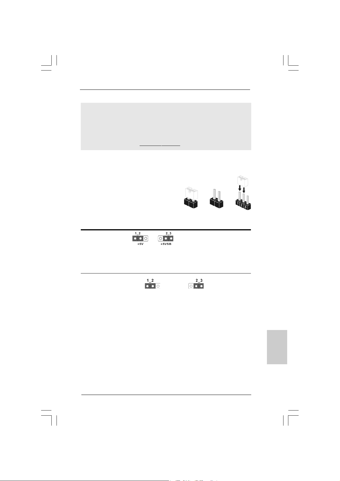
10. O cabeçalho WiFi/E suporta a função Wifi+AP com o módulo ASRock
WiFi-802.11g ou WiFi-802.11n, um adaptador de rede de área local sem
fios (WLAN) fácil de utilizar. Permite-lhe criar um ambiente sem fios e
desfrutar da conveniência da conectividade de rede sem fios. Por
favor visite o nosso sítio para conhecer a disponibilidade do módulo
ASRock WiFi-802.11g / WiFi-802.1 1n.
Sítio da ASRock http://www.asrock.com
1.3 Configuração dos Jumpers1.3 Configuração dos Jumpers
1.3 Configuração dos Jumpers
1.3 Configuração dos Jumpers1.3 Configuração dos Jumpers
A ilustração mostra como os jumpers são
configurados. Quando há uma capa de
jumpers sobre os pinos, diz–se que o jumper
está “curto”. Não havendo capa sobre os
pinos, o jumper está “aberto”. A ilustração
mostra um jumper de 3 pinos em que os pinos
1 e 2 están “curtos” quando a ca pa de jumper
estiver colocada sobre esses 2 pinos.
Jumper Configuração
PS2_USB_PW1 Pin2, Pin3 curtos para
(veja a folha 2, No. 1) habilitar +5VSB (stand by)
Nota: Para escolher +5VSB, é preciso uma corrente de stand by de 2 A ou mais.
Short Open
para PS/2 ou eventos de
wake up na USB.
Restaurar CMOS
(CLRCMOS1, jumper de 3 pinos)
(veja a folha 2, No. 10)
Nota: CLRCMOS1 permite você limpar os dados em CMOS. Os dados em CMOS
incluem informações da configuração do sistema como: por exemplo a senha
do sistema, data, tempo, e os parámetros da configuração do sistema. Para
limpar e reconfigurar os parámetros do sistema a configuração inicial da
fábrica, por favor desligue o cabo de força, ponha em curto–circuito os pin 2
e pin 3 de CLRCMOS1 por mais de 5 segundos para limpar o CMOS usando um
jumper. Por favor lembrese de remover o jumper depois de limpar o COMS. Se
precisar limpar o CMOS ao concluir a atualização do BIOS, deverá reiniciar o
sistema primeiro e, em seguida, desligá-lo antes de executar a ação de limpeza
o CMOS.
Configuração-padrão Limpar o CMOS
ASRock 4CoreN73PV-HD720p Motherboard
8585
85
8585
PortuguêsPortuguês
PortuguêsPortuguês
Português
Page 76

Português
PortuguêsPortuguês
PortuguêsPortuguês
1.4 Conectores1.4 Conectores
1.4 Conectores
1.4 Conectores1.4 Conectores
Os conectores NÃO SÃO jumpers. NÃO coloque capas de jumper sobre
estes conectores. A colocação de pontos de jumper sobre os conectores
causará danos irreversíveis à placa-mãe.
Conector Figura Descrição
Conector F DD
(FLOPPY 1, 33 pinos)
(veja a folha 2, No. 18)
o lado com listras vermelha s para o Pino 1
Nota: Certifique-se de que o lado com listras vermelhas no cabo seja conectado ao
lado Pino 1 do conector.
Conector primário (Azul)
(IDE1 de 39 pinos, veja a folha 2, No. 8)
Ligue esta ponta (azul) Ligue esta ponta (preta)
à placa–mãe aos dispositivos IDE
Cabo ATA 66/100/133 de 80 condutores
Nota: Para detalhes, consulte as instruções do fornecedor do seu dispositivo
IDE.
Conectores A TAII Serial Estes quatro conectores Serial
(SAT AII_1 (PORT1.0): ATA (SATAII) suportam
veja a folha 2, No. 15) unidades de disco rígido SATA
(SAT AII_2 (PORT1.1): ou SATAII como dispositivos de
veja a folha 2, No. 14) armazenamento internos. A
(SAT AII_3 (PORT1.2): atual interface SATAII permite
veja a folha 2, No. 13) uma taxa de transferência de
(SAT AII_4 (PORT1.3): dados de até 3.0 Gb/s.
veja a folha 2, No. 12)
SATAII_1 (PORT1.0)
SATAII_2 (PORT1.1)
SAT AII_3 (PORT1.2)
SAT AII_4 (PORT1.3)
Cabo de dados Tanto a saída do cabo de Serial
ATA (SATA) dados SATA pode ser
(opcional) conectado ao disco rígido
SATA / SATAII quanto o
conector SATAII na placa mãe.
8686
86
8686
ASRock 4CoreN73PV-HD720p Motherboard
Page 77

Cabo de Alimentação Conecte a saída de cor preta
ATA (SATA) do cabo de alimentação SATA
(opcional) ao conector de alimentação
Ligue no conector de
alimentação SAT A HDD
Conecte a fonte
em cada acionador. Em
seguida, conecte a saída
branca do cabo de alimentação
SATA ao conector de
alimentação da fonte.
Cabezal USB 2.0 Além das quatro portas USB
(USB6_7 de 9 pinos) 2.0 por defeito no painel de
(veja a folha 2, No. 27) entrada/saída, há duas
ligações USB 2.0 nesta placamãe. Cada ligação USB 2.0
pode suportar duas portas USB
(USB4_5 de 9 pinos) 2.0.
(veja a folha 2, No. 28)
Cabeçalho WiFi/E CEste cabeçalho suporta a
(WIFI/E, 15 pinos) função WiFi+AP com o módulo
(veja a folha 2, No. 20) WiFi-802.11g ou WiFi-802.11n,
um adaptador de rede de área
local sem fios (WLAN) fácil de
utilizar. Permite-lhe criar um
ambiente sem fios e desfrutar
da conveniência da
conectividade de rede sem
fios.
Se não tiver intenções de utilizar a função Wifi+AP nesta aplicação, este
conector pode ser utilizado como conector USB 2.0 de 4 pinos para
suportar uma porta USB 2.0. Para conectar o cabo do dispositivo USB de 4
pinos a este conector, por favor refira-se a esta imagem para uma
instalação própria.
Suporte de Detecção Automática de Este suporte suporta a função
Periféricos DeskExpress detecção automática de
(IR1 de 5 pinos) de Periféricos para ASRock
(veja a folha 2, No. 19) DeskExpress.
ASRock 4CoreN73PV-HD720p Motherboard
8787
87
8787
PortuguêsPortuguês
PortuguêsPortuguês
Português
Page 78

Conectores internos de áudio Estes conectores permitem
(CD1 de 4 pinos) que se receba entrada de
(CD1: veja a floha 2, No. 23) áudio em estéreo de fontes
CD1
de áudio como CD-ROM,
DVD-ROM, placa sintonizadora
de TV ou pla ca MPEG.
Conector Áudio do painel Esta é uma interface para o
frontal cabo de áudio no painel frontal,
(HD_AUDIO1 de 9 pinos) que permite uma conexão e
(veja a folha 2, No. 21) controle convenientes dos
dispositivos de áudio.
1. Áudio de elevada definição que suporta a sensibilidade da tomada, mas
o fio do painel existente no chassis tem de suportar HDA para funcionar
correctamente. Siga s instruções que aparecem no manual e no manual
do chassis para instalar o sistema.
2. Se utilizar o painel de áudio AC’97, instale-o no cabeçalho de áudio do
painel frontal, como a figura abaixo mostra:
A. Ligue o Mic_IN (MIC) ao MIC2_L.
B. Ligue o Audio_R (RIN) ao OUT2_R e o Audio_L (LIN) ao OUT2_L.
C. Ligue o Ground (GND) ao Ground (GND).
D. MIC_RET e OUT_RET são apenas para o painel de áudio HD. Não
necessita de os ligar para o painel de áudio AC’97.
E. Entre no utilitário de configuração do BIOS. Vá até à opção Definições
avançadas e escolha Configuração do chipset. Defina a opção Controlo
do painel frontal de [Automático] para [Activado].
F. Entre no sistema Windows. Clique no ícone existente na barra de
tarefas no canto inferior direito para aceder ao Realtek HD Audio
Manager.
Para Windows® XP / XP 64-bit OS:
Clique em “Entrada/Saída de áudio”, seleccione “Definições do
conector” , escolha a opção “Desactivar detecção da tomada do
Português
PortuguêsPortuguês
PortuguêsPortuguês
8888
88
8888
painel frontal” e guarde a alteração clicando em “OK”.
Para Windows® VistaTM / VistaTM 64-bit OS:
Clique o direito-cima “Folder” icone , escolhe “Deteção de
valete de painel dianteiro” e guarda a mudança por clicar “OK”.
Conector do sistema no Este conector acomoda
painel diversas funções de
(PANEL1 de 9 pinos) sistema no painel frontal.
(veja a folha 2, No. 11)
ASRock 4CoreN73PV-HD720p Motherboard
Page 79

Conector do alto-falante do chassi Ligue o alto-falante do chassi
(SPEAKER1 de 4 pinos) neste conector.
(veja a folha 2, No. 17)
Conector do ventilador do Ligue o cabo do ventilador neste
chassis conector, coincidindo o fio preto
(CHA_FAN1 de 3 pinos) com o pino de aterramento.
(veja a folha 2, No. 16)
Conector do ventilador da Ligue o cabo do ventilador da
4 3 2 1
C PU CPU, coincidindo o fio preto com
(CPU_FAN1 de 4 pinos) o pino de aterramento.
(veja a folha 2, No. 5)
Apesar de esta placa-mãe possuir 4 apoios para uma ventoinha de CPU
(Ventoinha silenciosa), uma ventoinha de 3 pinos para CPU poderá funcionar
mesmo sem a função de controlo de velocidade da ventoinha. Se pretender
ligar uma ventoinha de 3 pinos para CPU ao conector de ventoinha do CPU
nesta placa-mãe, por favor, ligue-a aos pinos 1-3.
Pinos 1-3 ligados
Instalação de Ventoinha de 3 pinos
24
Conector de força do ATX Ligue a fonte de alimentação
(ATXPWR1 de 24 pinos) ATX neste conector.
(veja a folha 2, No. 2)
Embora esta placa-mãe providencie um conector de energia
ATX de 24 pinos, pode apesar disso funcionar com a adapta-ção
de uma fonte de energia tradicional de 20 pinos. Para usar a fonte
de alimentação de 29 pinos, por favor ligue a sua fonte de
alimentação com o Pino 1 e o Pino 13.
12
13
1
Instalação da Fonte de alimentação ATX de 20 Pinos
12
1
24
13
Conector ATX 12 V Note que é necessário ligar
(ATX12V1 de 4 pinos ) uma fonte de alimentação com
(veja a folha 2, No. 3) conector ATX 12V neste
conector para fornecer
alimentação suficiente. Do
contrário, haverá falhas de
funcionamento.
ASRock 4CoreN73PV-HD720p Motherboard
8989
89
8989
PortuguêsPortuguês
PortuguêsPortuguês
Português
Page 80

Conector da porta COM Este conector é usado para
(COM1 de 9 pinos) suportar um módulo de porta
(veja a folha 2, No. 9) COM.
2. Informações da BIOS2. Informações da BIOS
2. Informações da BIOS
2. Informações da BIOS2. Informações da BIOS
O Utilitário de Configuração do BIOS está armazenado no chip FWH do BIOS. Ao
iniciar o computador, pressione <F2> durante o Autoteste de iniciação (POST)
para acessar o Utilitário de Configuração do BIOS; caso contrário, o POST
continuará com as rotinas de teste. Se desejar acessar o Utilitário de
Configuração do BIOS depois do POST, reinicie o sistema pressionando <Ctl> +
<Alt> + <Del>, ou pressionando o botão de reinício no chassi do sistema. Para as
informações detalhadas sobre o Utilitário de Configuração do BIOS, consulte o
Manual do Usuário (arquivo PDF) no CD de suporte.
3. Informações do CD de Suporte3. Informações do CD de Suporte
3. Informações do CD de Suporte
3. Informações do CD de Suporte3. Informações do CD de Suporte
Esta placa Mãe suporta vários sistemas operacionais: Microsoft® Windows®: XP / XP
de 64 bits / VistaTM / VistaTM de 64 bits. O CD de instalação que acompanha a placa
Mãe contem: drivers e utilitários necessários para um melhor desempenho da placa
Mãe. Para começar a usar o CD de instalação, introduza o CD na leitora de CD-ROM
do computador. Automaticamente iniciará o menu principal, casa o AUTORUN esteja
ativado. Se o menu principal não aparecer automaticamente, explore o CD e execute
o “ASSETUP.EXE” localizado na pasta BIN.
Português
PortuguêsPortuguês
PortuguêsPortuguês
9090
90
9090
ASRock 4CoreN73PV-HD720p Motherboard
Page 81

ASRock 4CoreN73PV-HD720p Motherboard
9191
91
9191
Page 82

®
®
®
®
®
9292
92
9292
®
ASRock 4CoreN73PV-HD720p Motherboard
Page 83

®
ASRock 4CoreN73PV-HD720p Motherboard
9393
93
9393
Page 84
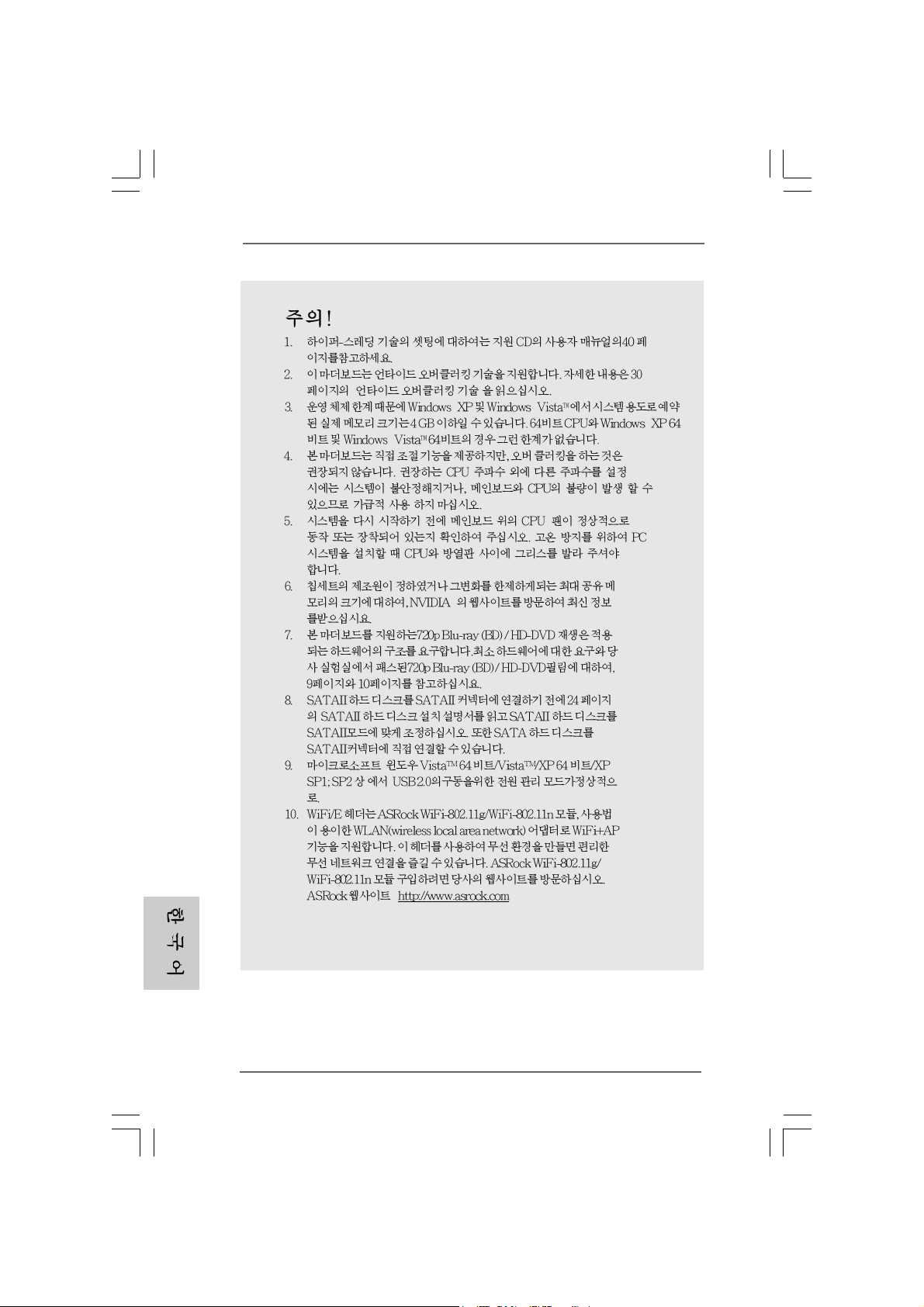
“ ”
®
“
® ®
®
®
9494
94
9494
ASRock 4CoreN73PV-HD720p Motherboard
Page 85

“ ”
“ ”
“ ”
“ ”
ASRock 4CoreN73PV-HD720p Motherboard
9595
95
9595
Page 86

9696
96
9696
SAT AII_2 (PORT1.1)
SAT AII_1 (PORT1.0)
SAT AII_3 (PORT1.2)
SAT AII_4 (PORT1.3)
ASRock 4CoreN73PV-HD720p Motherboard
Page 87

CD1
ASRock 4CoreN73PV-HD720p Motherboard
9797
97
9797
Page 88

9898
98
9898
®
®
®
ASRock 4CoreN73PV-HD720p Motherboard
Page 89

4 3 2 1
12
1
24
13
12
24
1
13
9999
99
9999
ASRock 4CoreN73PV-HD720p Motherboard
Page 90

\ \
“ ”
“ ”
100100
100
100100
ASRock 4CoreN73PV-HD720p Motherboard
Page 91

ASRock 4CoreN73PV-HD720p Motherboard
101101
101
101101
Page 92

®
®
®
®
®
102102
102
102102
®
ASRock 4CoreN73PV-HD720p Motherboard
Page 93
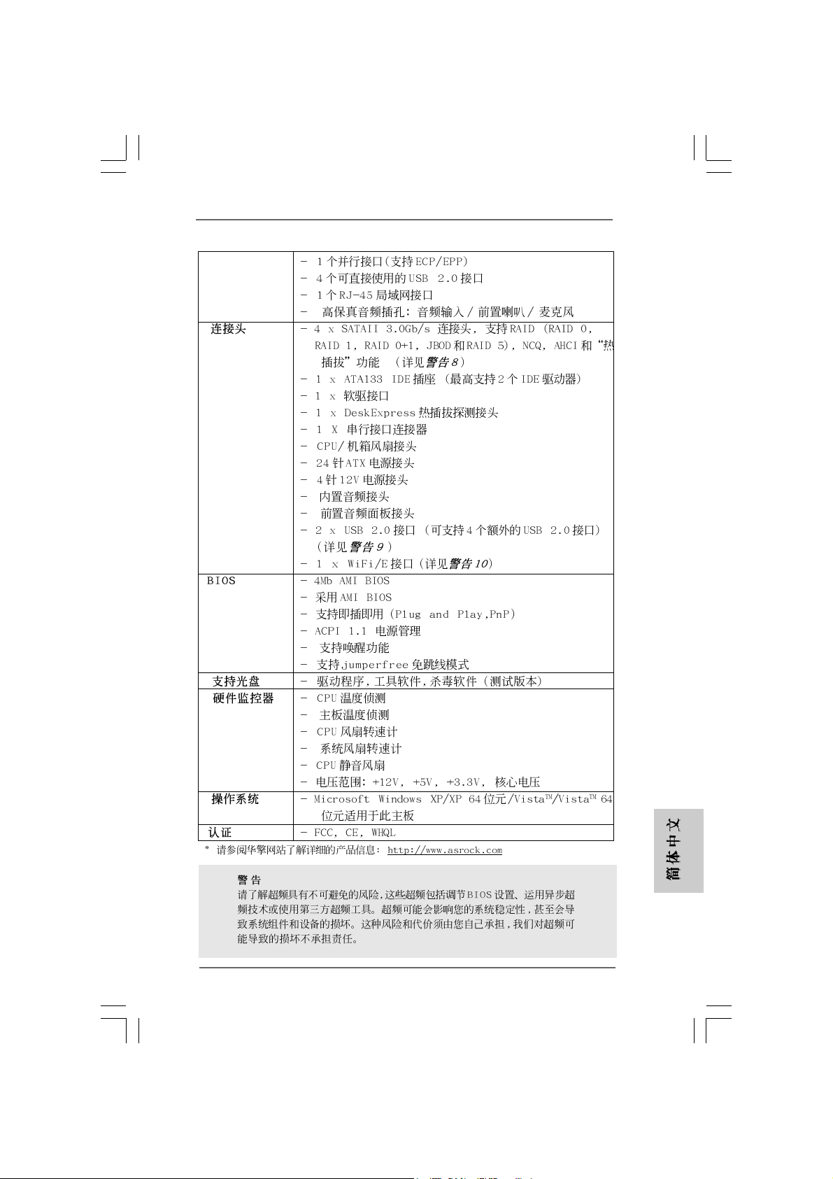
®
®
ASRock 4CoreN73PV-HD720p Motherboard
103103
103
103103
Page 94

® ®
®
®
®
®
104104
104
104104
ASRock 4CoreN73PV-HD720p Motherboard
Page 95

ASRock 4CoreN73PV-HD720p Motherboard
105105
105
105105
Page 96

106106
106
106106
SAT AII_2 (PORT1.1)
SAT AII_1 (PORT1.0)
SAT AII_3 (PORT1.2)
SAT AII_4 (PORT1.3)
ASRock 4CoreN73PV-HD720p Motherboard
Page 97

CD1
ASRock 4CoreN73PV-HD720p Motherboard
107107
107
107107
Page 98

®
®
108108
108
108108
4 3 2 1
ASRock 4CoreN73PV-HD720p Motherboard
Page 99

24
12
13
1
12
24
1
13
ASRock 4CoreN73PV-HD720p Motherboard
109109
109
109109
Page 100
® ®
110110
110
110110
ASRock 4CoreN73PV-HD720p Motherboard
 Loading...