

Page 1
Copyright Notice:Copyright Notice:
Copyright Notice:
Copyright Notice:Copyright Notice:
No part of this installation guide may be reproduced, transcribed, transmitted, or translated in any language, in any form or by any means, except duplication of documentation by the purchaser for backup purpose, without written consent of ASRock Inc.
Products and corporate names appearing in this guide may or may not be registered
trademarks or copyrights of their respective companies, and are used only for identification or explanation and to the owners’ benefit, without intent to infringe.
Disclaimer:Disclaimer:
Disclaimer:
Disclaimer:Disclaimer:
Specifications and information contained in this guide are furnished for informational
use only and subject to change without notice, and should not be constructed as a
commitment by ASRock. ASRock assumes no responsibility for any errors or omissions
that may appear in this guide.
With respect to the contents of this guide, ASRock does not provide warranty of any kind,
either expressed or implied, including but not limited to the implied warranties or
conditions of merchantability or fitness for a particular purpose. In no event shall
ASRock, its directors, officers, employees, or agents be liable for any indirect, special,
incidental, or consequential damages (including damages for loss of profits, loss of
business, loss of data, interruption of business and the like), even if ASRock has been
advised of the possibility of such damages arising from any defect or error in the guide
or product.
This device complies with Part 15 of the FCC Rules. Operation is subject to the
following two conditions:
(1) this device may not cause harmful interference, and
(2) this device must accept any interference received, including interference that
may cause undesired operation.
CALIFORNIA, USA ONLY
The Lithium battery adopted on this motherboard contains Perchlorate, a toxic
substance controlled in Perchlorate Best Management Practices (BMP) regulations
passed by the California Legislature. When you discard the Lithium battery in
California, USA, please follow the related regulations in advance.
“Perchlorate Material-special handling may apply, see
www.dtsc.ca.gov/hazardouswaste/perchlorate”
ASRock Website: http://www.asrock.com
Published March 2007
Copyright©2007 ASRock INC. All rights reserved.
ASRock 4CoreDX90-VSTA Motherboard
EnglishEnglish
EnglishEnglish
English
11
1
11
Page 2
Motherboard LMotherboard L
Motherboard L
Motherboard LMotherboard L
ayoutayout
ayout
ayoutayout
English
EnglishEnglish
EnglishEnglish
22
2
22
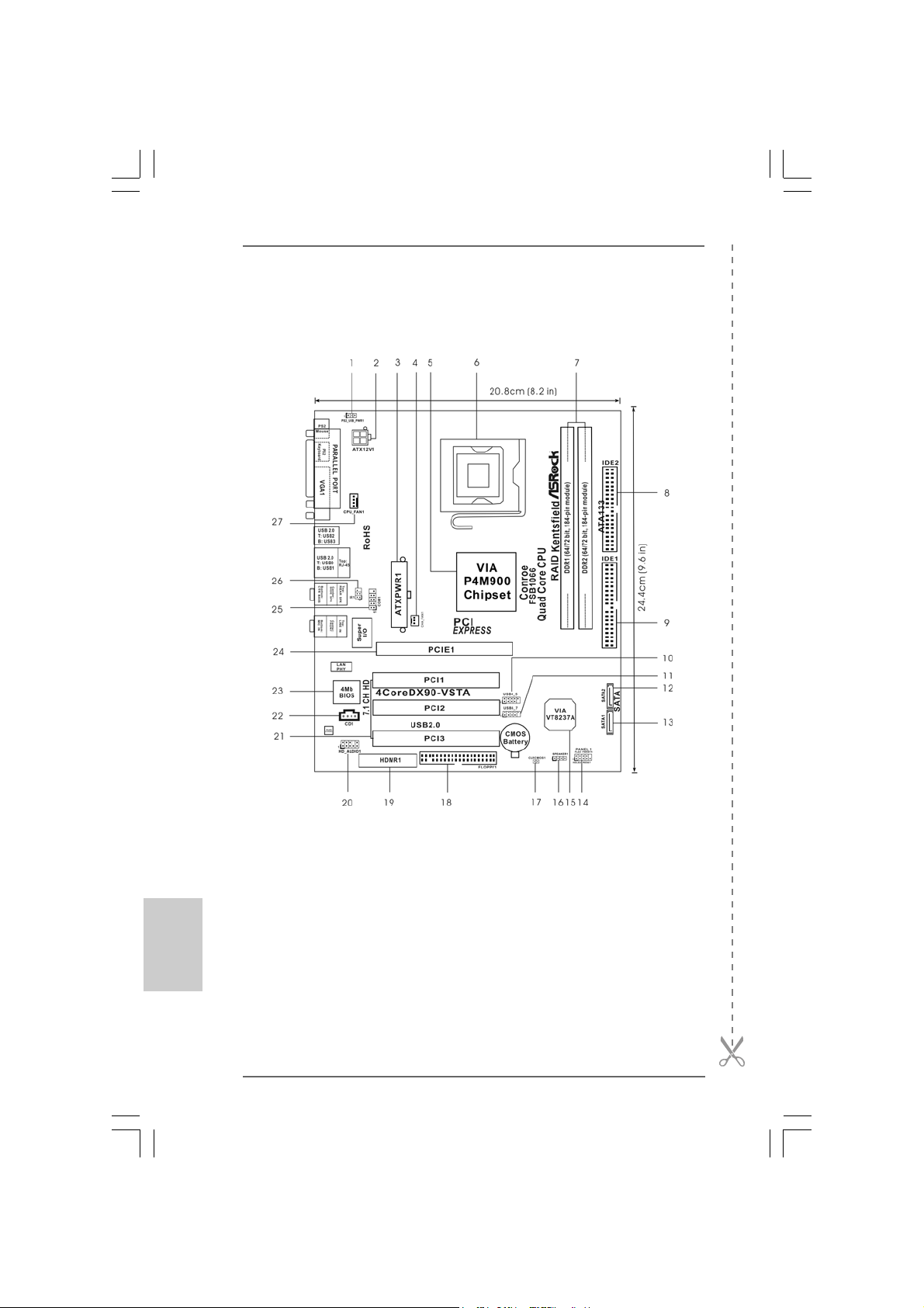
1 PS2_USB_PWR1 Jumper 15 South Bridge Controller
2 A TX 12V Connector (A TX12V1) 16 Chassis Speaker Header (SPEAKER 1)
3 A TX Power Connector (ATXPWR1) 17 Clear CMOS Jumper (CLRCMOS1)
4 Chassis Fan Connector (CHA_FAN1) 18 Floppy Connector (FLOPPY1)
5 North Bridge Controller 19 HDMR Slot (HDMR1)
6 775-Pin CPU Socket 20 Front Panel Audio Header (HD_AUDIO1)
7 2 x 184-pin DDR DIMM Slots (DDR1, DDR2; Blue) 21 3 x PCI Slots (PCI1- 3)
8 Secondary IDE Connector (IDE2, Black) 22 Internal Audio Connector: CD1 (Black)
9 Primary IDE Connector (IDE1, Blue) 23 Flash Memory
10 USB 2.0 Header (USB4_5, Blue) 24 PCI Express x16 Slot (PCIE1)
11 USB 2.0 Header (USB6_7, Blue) 25 Serial Port Connector (COM1)
12 Secondary Serial A T A Conne ctor (SA T A2 ) 26 Infrared Module Header (IR1)
13 Primary Serial A T A Conne ctor (SA T A1) 27 CPU Fan Connector (CPU_FAN1)
14 System Panel Header (PANEL1)
ASRock 4CoreDX90-VSTA Motherboard
Page 3
HD 8CH I/OHD 8CH I/O
HD 8CH I/O
HD 8CH I/OHD 8CH I/O
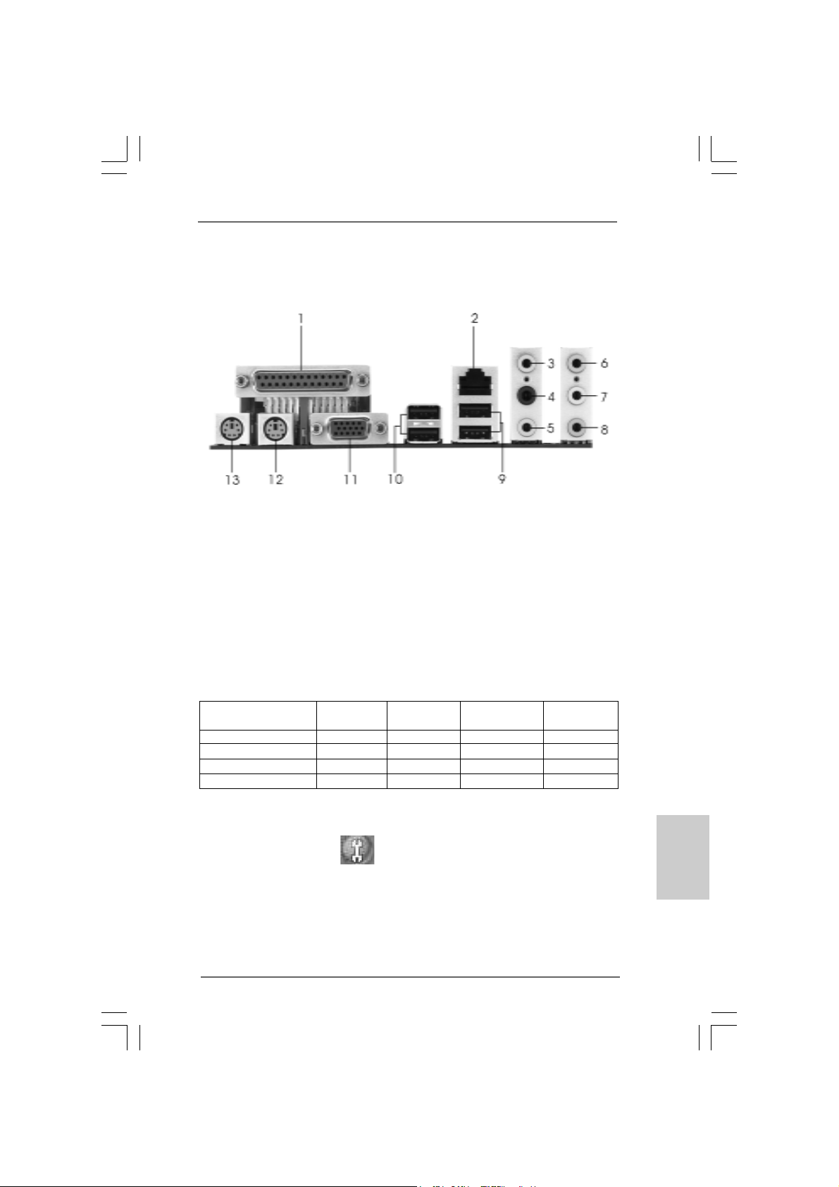
1 Parallel Port 8 Microphone (Pink)
2 RJ-45 Port 9 USB 2.0 Ports (USB01)
3 Side Speaker (Gray) 10 USB 2.0 Ports (USB23)
4 Rear Speaker (Black) 11 VGA Port
5 Central / Bass (Orange) 12 PS/2 Keyboard Port (Purple)
6 Line In (Light Blue) 13 PS/2 Mouse Port (Green)
*7 Front Speaker (Lime)
* If you use 2-channel spea ker, please connect the speaker’s plug into “Front Speaker Jack”. See
the table below for connection details in accordance with the type of speaker you use.
TABLE for Audio Output Connection
Audio Output Channels Front Speaker Rear Speaker Central / Bass Side Speaker
(No. 7) (No. 4) (No. 5) (No. 3)
2 V -- -- -4VV---6 VVV-8 VVVV
* To enable Multi-Streaming function, you need to connect a front panel audio cable to the front
panel audio header. After restarting your computer, you will find “Mixer” tool on your system.
Please select “Mixer ToolBox” , click “Enable playback multi-streaming”, and click
“ok”. Choose “2CH”, “4CH”, “6CH”, or “8CH” and then you are allowed to select “Realtek HDA
Primary output” to use Rear Speaker, Central/Bass, and Front Speaker, or select “Realtek HDA
Audio 2nd output” to use front panel audio.
ASRock 4CoreDX90-VSTA Motherboard
EnglishEnglish
EnglishEnglish
English
33
3
33
Page 4
1. Introduction1. Introduction
1. Introduction
1. Introduction1. Introduction
Thank you for purchasing ASRock 4CoreDX90-VSTA motherboard, a reliable moth-
erboard produced under ASRock’s consistently stringent quality control. It delivers
excellent performance with robust design conforming to ASRock’s commitment to
quality and endurance.
This Quick Installation Guide contains introduction of the motherboard and step-bystep installation guide. More detailed information of the motherboard can be found in
the user manual presented in the Support CD.
Because the motherboard specifications and the BIOS software might
be updated, the content of this manual will be subject to change
without notice. In case any modifications of this manual occur, the
updated version will be available on ASRock website without further
notice. You may find the latest VGA cards and CPU support lists on
ASRock website as well.
ASRock website
1.1 Package Contents1.1 Package Contents
1.1 Package Contents
1.1 Package Contents1.1 Package Contents
ASRock 4CoreDX90-VSTA Motherboard
(Micro ATX Form Factor: 9.6-in x 8.2-in, 24.4 cm x 20.8 cm)
ASRock 4CoreDX90-VSTA Quick Installation Guide
ASRock 4CoreDX90-VSTA Support CD
One 80-conductor Ultra ATA 66/100/133 IDE Ribbon Cable
One Ribbon Cable for a 3.5-in Floppy Drive
One Serial ATA (SATA) Cable (Optional)
One Serial ATA (SATA) HDD Power Cable (Optional)
One HD 8CH I/O Panel Shield
One COM Port Bracket
http://www.asrock.com
English
EnglishEnglish
EnglishEnglish
44
4
44
ASRock 4CoreDX90-VSTA Motherboard
Page 5
1.21.2
SpecificationsSpecifications
1.2
Specifications
1.21.2
SpecificationsSpecifications
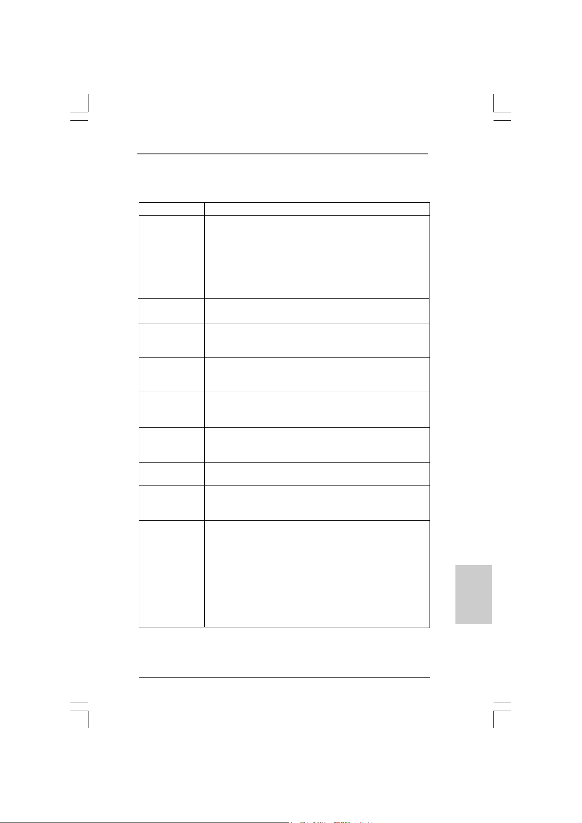
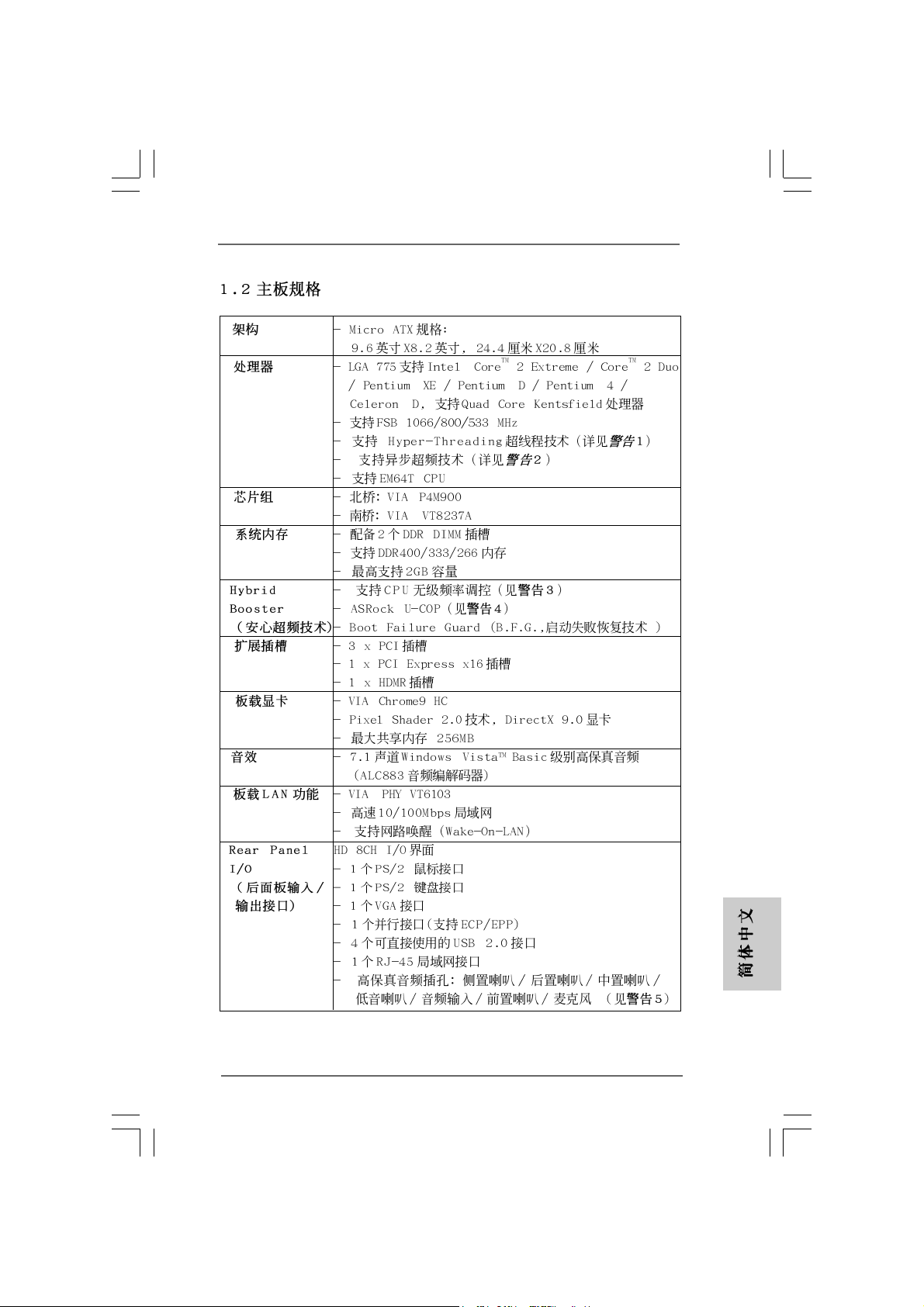
Platform - Micro ATX Form Factor: 9.6-in x 8.2-in, 24.4 cm x 20.8 cm
CPU - LGA 775 for Intel® CoreTM 2 Extreme / CoreTM 2 Duo /
Pentium® XE / Pentium® D / Pentium® 4 / Celeron® D, supporting
Quad Core Kentsfield processors
- FSB 1066/800/533 MHz
- Supports Hyper-Threading Technology (see CAUTION 1)
- Supports Untied Overclocking Technology (see CAUTION 2)
- Supports EM64T CPU
Chipset - Northbridge: VIA® P4M900
- Southbridge: VIA® VT8237A
Memory - 2 x DDR DIMM slots
- Support DDR400/333/266
- Max. capacity: 2GB
Hybrid Booster - CPU Frequency Stepless Control (see CAUTION 3)
- ASRock U-COP (see CAUTION 4)
- Boot Failure Guard (B.F.G.)
Expansion Slot - 3 x PCI slots
- 1 x PCI Express x16 slot
- 1 x HDMR slot
Graphics - VIA® Chrome9 HC
- Pixel Shader 2.0, DirectX 9.0
- Max. shared memory 256MB
Audio - 7.1 CH Windows® VistaTM Basic Level HD Audio
(ALC883 Audio Codec)
LAN - VIA® PHY VT6103
- Speed: 10/100 Ethernet
- Supports Wake-On-LAN
Rear Panel I/O HD 8CH I/O
- 1 x PS/2 Mouse Port
- 1 x PS/2 Keyboard Port
- 1 x VGA Port
- 1 x Parallel Port (ECP/EPP Support)
- 4 x Ready-to-Use USB 2.0 Ports
- 1 x RJ-45 Port
- HD Audio Jack: Side Speaker/Rear Speaker/Central Bass/
Line in/Front Speaker/Microphone (see CAUTION 5)
EnglishEnglish
EnglishEnglish
English
ASRock 4CoreDX90-VSTA Motherboard
55
5
55
Page 6
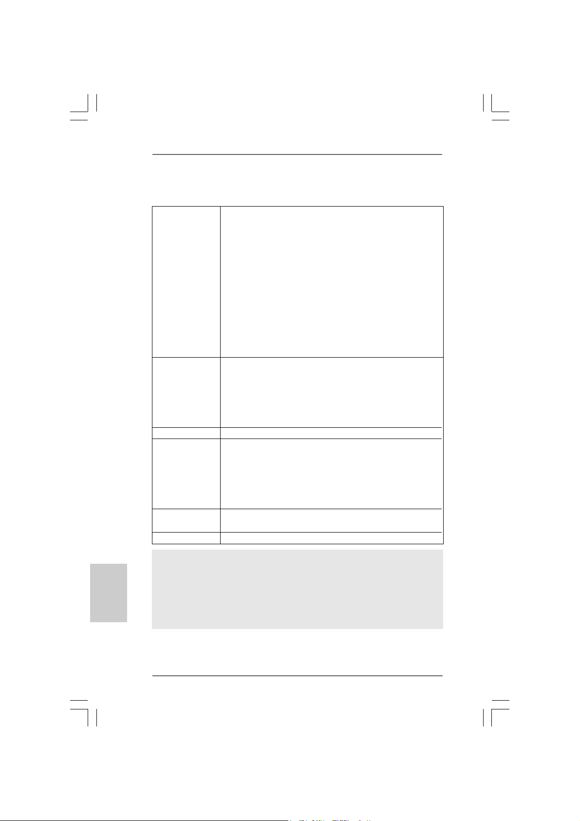
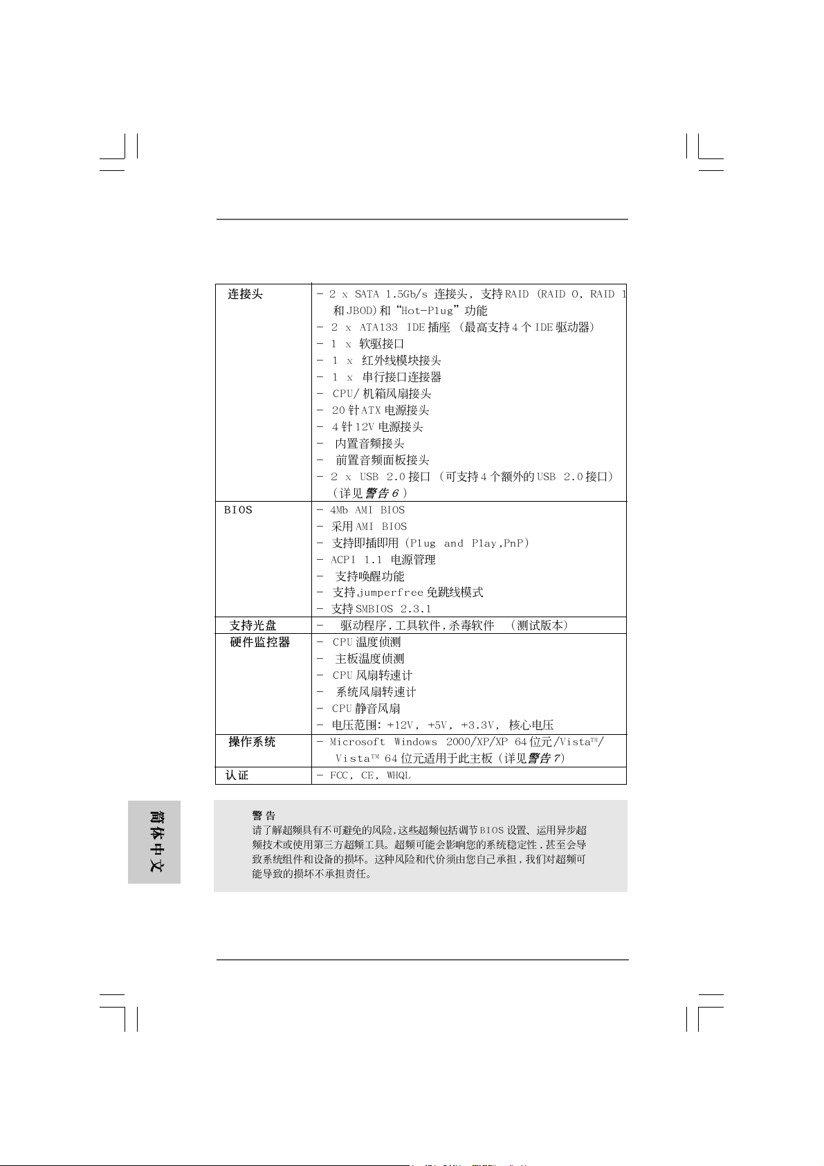
Connector - 2 x Serial ATA 1.5Gb/s connectors, support RAID (RAID 0,
RAID 1 and JBOD) and “Hot Plug” functions
- 2 x ATA133 IDE connectors (support 4 x IDE devices)
- 1 x Floppy connector
- 1 x IR header
- 1 x COM port header
- CPU/Chassis FAN connector
- 20 pin ATX power connector
- 4 pin 12V power connector
- CD in header
- Front panel audio connector
- 2 x USB 2.0 headers (support 4 USB 2.0 ports)
(see CAUTION 6)
BIOS Feature - 4Mb AMI BIOS
- AMI Legal BIOS
- Supports “Plug and Play”
- ACPI 1.1 Compli ance Wake Up Events
- Supports jumperfree
- SMBIOS 2.3.1 Support
Support CD - Drivers, Utilities, AntiVirus Software (Trial Version)
Hardware - CPU Temperature Sensing
Monitor - Chassis Temperature Sensing
- CPU Fan Tachometer
- Chassis Fan Tachometer
- CPU Quiet Fan
- Voltage Monitoring: +12V, +5V, +3.3V, Vcore
OS - Microsoft® Windows® 2000 / XP / XP 64-bit / Vista
TM
/
VistaTM 64-bit compliant (see CAUTION 7)
Certifications - FCC, CE, WHQL
English
EnglishEnglish
EnglishEnglish
66
6
66
WARNING
Please realize that there is a certain risk involved with overclocking, including adjusting
the setting in the BIOS, applying Untied Overclocking Technology, or using the thirdparty overclocking tools. Overclocking may affect your system stability, or even
cause damage to the components and devices of your system. It should be done at
your own risk and expense. We are not responsible for possible damage caused by
overclocking.
ASRock 4CoreDX90-VSTA Motherboard
Page 7
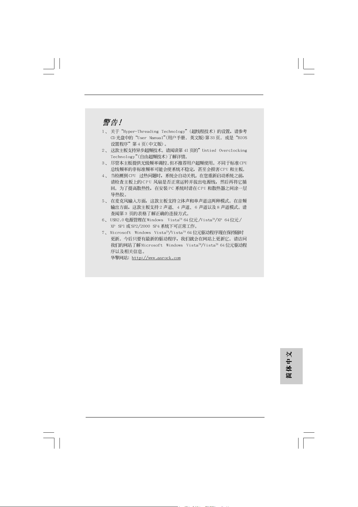
CAUTION!
1. About the setting of “Hyper Threading Te chnology”, please check page 33
of “User Manual” in the support CD.
2. This motherboard supports Untied Overclocking Technology. Please read
“Untied Overclocking Technology” on page 22 for details.
3. Although this motherboard offers stepless control, it is not recommended
to perform over-clocking. Frequencies other than the recommended CPU
bus frequencies may cause the instability of the system or damage the
CPU.
4. While CPU overheat is detected, the system will automatically shutdown.
Before you resume the system, please check if the CPU fan on the
motherboard functions properly and unplug the power cord, then plug it
back again. To improve heat dissipation, remember to spray thermal
grease between the CPU a nd the he atsink when you install the PC syste m.
5. For microphone input, this motherboard supports both stereo and mono
modes. For audio output, this motherboard supports 2-channel, 4-channel,
6-channel, and 8-channel modes. Please check the table on page 3 for
proper connection.
6. Power Management for USB 2.0 works fine under Microsoft® Windows
VistaTM 64-bit / VistaTM / XP 64-bit / XP SP1 or SP2 / 2000 SP4.
7. Microsoft® Windows® VistaTM / VistaTM 64-bit driver keeps on updating now. As
long as we have the latest driver, we will update it to our website in the future.
Please visit our website for Microsoft® Windows® VistaTM / VistaTM 64-bit driver
and related information.
ASRock website http://www.asrock.com
®
ASRock 4CoreDX90-VSTA Motherboard
EnglishEnglish
EnglishEnglish
English
77
7
77
Page 8
1.31.3
Minimum Hardware RMinimum Hardware R
1.3
Minimum Hardware R
1.31.3
Minimum Hardware RMinimum Hardware R
TMTM
TM
TMTM
VistaVista
Vista
VistaVista
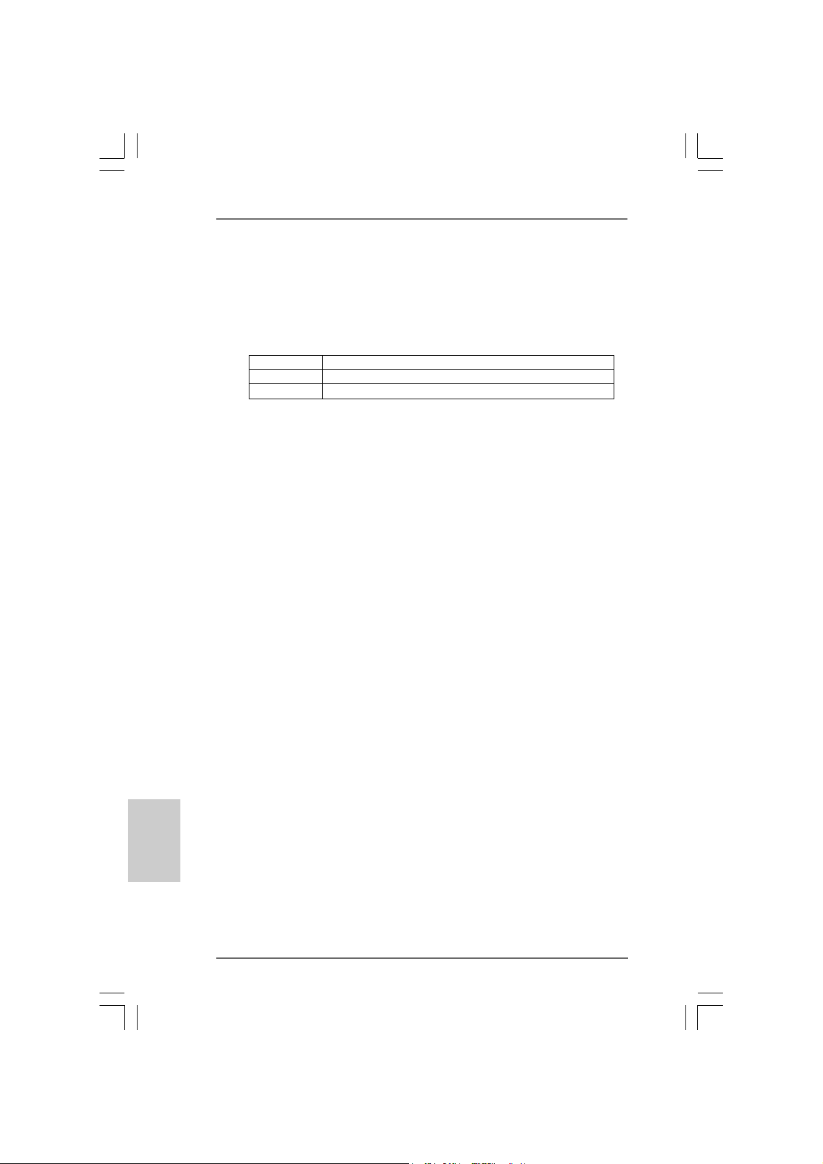
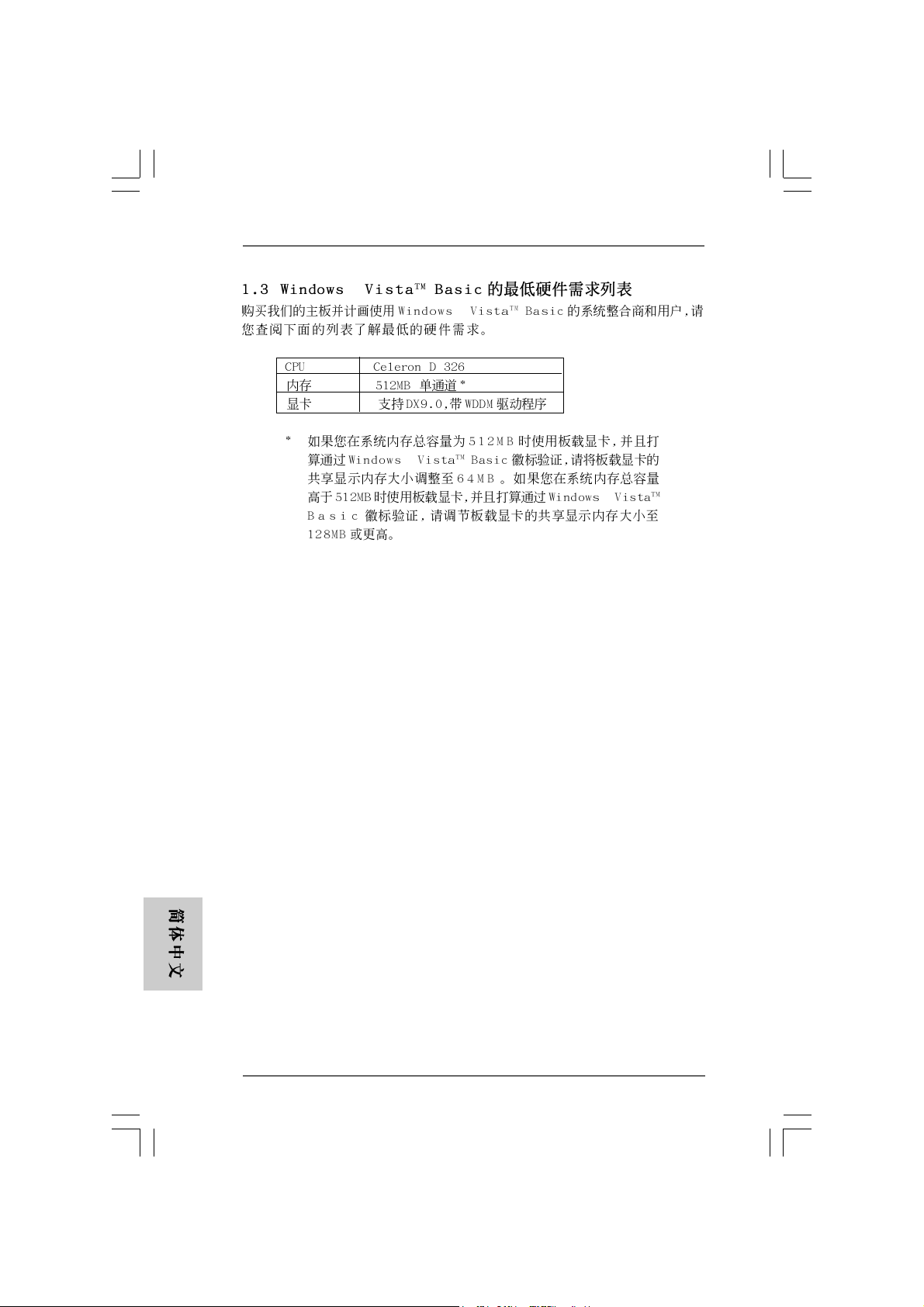
For system integrators and users who purchase our motherboard and
plan to submit Windows® VistaTM Basic logo, please follow below table for
minimum hardware requirement.
CPU Celeron D 326
Memory 512MB Single Channel*
VGA DX9.0 with WDDM Driver
* If you use onboard VGA with total system memory size 512MB and plan to
submit Windows® VistaTM Basic logo, please adjust the shared memory size of
onboard VGA to 64MB. If you use onboard VGA with total system memory size
above 512MB and plan to submit Windows® VistaTM Basic logo, please adjust the
shared memory size of onboard VGA to 128MB or above.
Basic Logo Basic Logo
Basic Logo
Basic Logo Basic Logo
equirement Tequirement T
equirement T
equirement Tequirement T
able for Wable for W
able for W
able for Wable for W
indowsindows
indows
indowsindows
®®
®
®®
English
EnglishEnglish
EnglishEnglish
88
8
88
ASRock 4CoreDX90-VSTA Motherboard
Page 9
2.2.
InstallationInstallation
2.
Installation
2.2.
InstallationInstallation
Pre-installation PrecautionsPre-installation Precautions
Pre-installation Precautions
Pre-installation PrecautionsPre-installation Precautions
Take note of the following precautions before you install motherboard components or change any motherboard settings.
1. Unplug the power cord from the wall socket before touching any
component. Failure to do so may cause severe damage to the
motherboard, peripherals, and/or components.
2. To avoid damaging the motherboard components due to static
electricity, NEVER place your motherboard directly on the carpet
or the like. Also remember to use a grounded wrist strap or touch
a safety grounded object before you handle components.
3. Hold components by the edges and do not touch the ICs.
4. Whenever you uninstall any component, place it on a grounded
antstatic pad or in the bag that comes with the component.
5. When placing screws into the screw holes to secure the
motherboard to the chassis, please do not over-tighten the
screws! Doing so may damage the motherboard.
2.12.1
CPU InstallationCPU Installation
2.1
CPU Installation
2.12.1
CPU InstallationCPU Installation
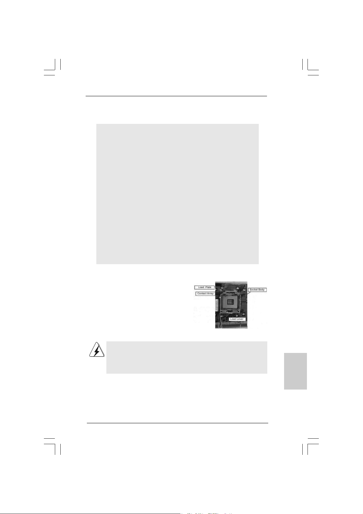
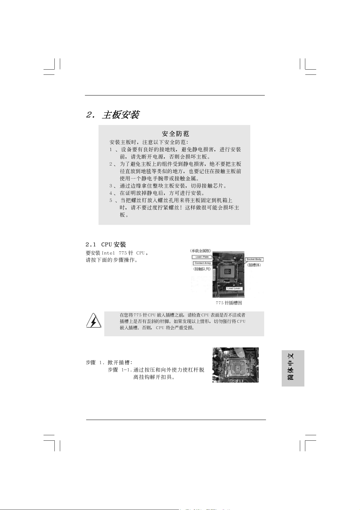
For the installation of Intel 775-LAND CPU,
please follow the steps below.
775-Pin Socket Overview
Before you insert the 775-LAND CPU into the socket, please check if
the CPU surface is unclean or if there is any bent pin on the socket.
Do not force to insert the CPU into the socket if above situation is
found. Otherwise, the CPU will be seriously damaged.
ASRock 4CoreDX90-VSTA Motherboard
EnglishEnglish
EnglishEnglish
English
99
9
99
Page 10
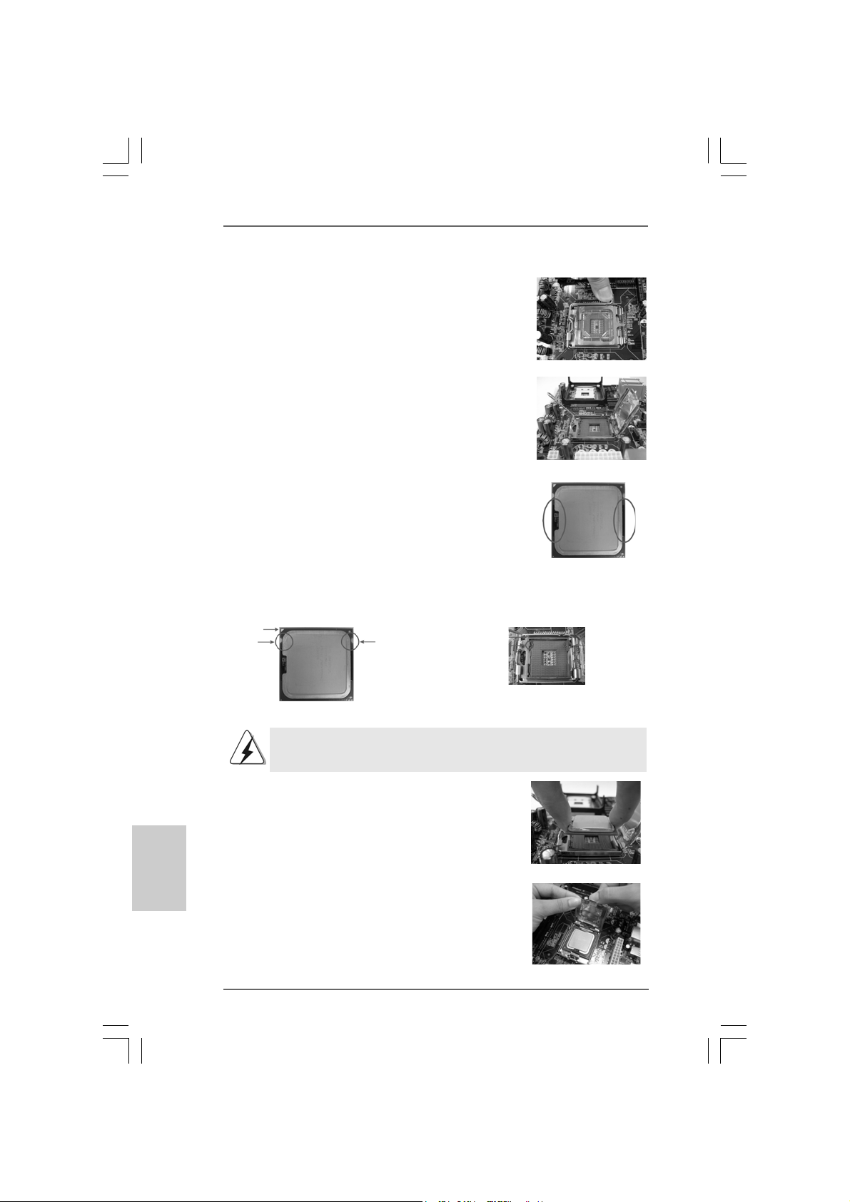
Step 1. Open the socket:
Step 1-1. Disengaging the lever by depressing
down and out on the hook to clear
retention tab.
Step 1-2. Rotate the load lever to fully open po-
sition at approximately 135 degrees.
Step 1-3. Rotate the load plate to fully open po-
sition at approximately 100 degrees.
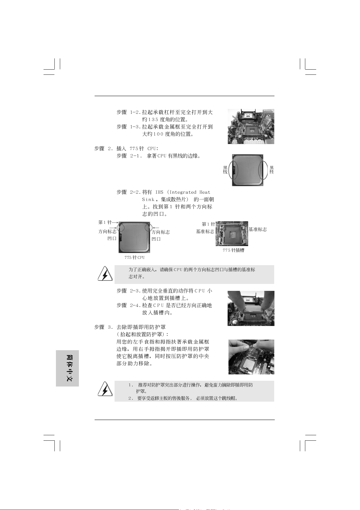
Step 2. Insert the 775-LAND CPU:
Step 2-1. Hold the CPU by the edges where are
marked with black lines.
Step 2-2. Orient the CPU with IHS (Integrated
Heat Sink) up. Locate Pin1 and the two
orientation key notches.
Pin1
orientation
key notch
orientation
key notch
Pin1
alignment key
black line
black line
alignment key
English
EnglishEnglish
EnglishEnglish
1010
10
1010
775-Pin Socket
775-LAND CPU
For proper inserting, please ensure to match the two orientation key
notches of the CPU with the two alignment keys of the socket.
Step 2-3. Carefully pla ce the CPU into the socket
by using a purely vertical motion.
Step 2-4. Verify that the CPU is within the socket
and properly mated to the orient keys.
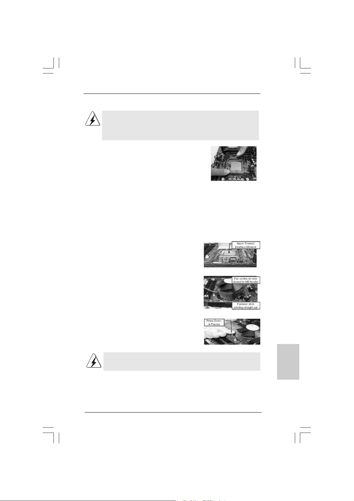
Step 3. Remove PnP Ca p (Pick a nd Place Ca p):
Use your left hand index finger and thumb to
support the load plate edge, engage PnP cap
with right hand thumb and peel the cap from the
socket while pressing on center of PnP cap to
assist in removal.
ASRock 4CoreDX90-VSTA Motherboard
Page 11
1. It is recommended to use the cap tab to handle and avoid kicking
off the PnP cap.
2. This cap must be placed if returning the motherboard for after
service.
Step 4. Close the socket:
Step 4-1. Rotate the load plate onto the IHS.
Step 4-2. While pressing down lightly on load
plate, engage the load lever.
Step 4-3. Secure load lever with load plate tab
under retention tab of load lever.
2.22.2
Installation of CPU Fan and HeatsinkInstallation of CPU Fan and Heatsink
2.2
Installation of CPU Fan and Heatsink
2.22.2
Installation of CPU Fan and HeatsinkInstallation of CPU Fan and Heatsink
For proper installation, please kindly refer to the instruction manuals of your CPU fan
and heatsink.
Below is an example to illustrate the installation of the heatsink for 775-LAND CPU.
Step 1. Apply thermal interface material onto center
of IHS on the socket surface.
Step 2. Place the heatsink onto the socket. Ensure
fan cables are oriented on side closest to the
CPU fan connector on the motherboard
(CPU_FAN1, see page 2, No. 4).
Step 3. Align fasteners with the motherboard
throughholes.
Step 4. Rotate the fastener clockwise, then press
down on fastener caps with thumb to install
and lock. Repeat with remaining fasteners.
If you press down the fasteners without rotating them clockwise, the heatsink cannot be
secured on the motherboard.
Step 5. Connect fan header with the CPU fan
connector on the motherboard.
Step 6. Secure excess cable with tie-wrap to ensure
cable does not interfere with fan operation or
contact other components.
ASRock 4CoreDX90-VSTA Motherboard
1111
11
1111
EnglishEnglish
EnglishEnglish
English
Page 12
2.32.3
Installation of Memory Modules (DIMM)Installation of Memory Modules (DIMM)
2.3
Installation of Memory Modules (DIMM)
2.32.3
Installation of Memory Modules (DIMM)Installation of Memory Modules (DIMM)
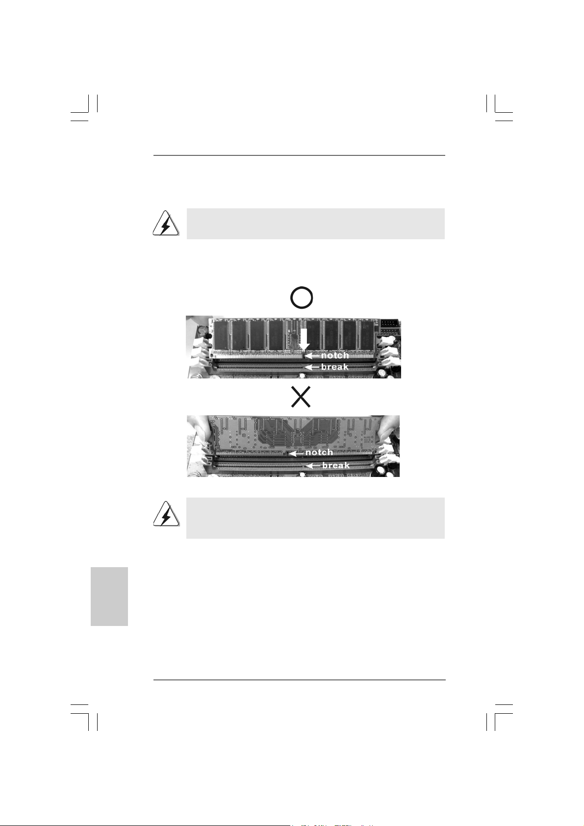
This motherboard is equipped with two 184-pin DDR (Double Data Rate) DIMM slots.
Please make sure to disconnect power supply before adding or
removing DIMMs or the system components.
Step 1. Unlock a DIMM slot by pressing the retaining clips outward.
Step 2. Align a DIMM on the slot such that the notch on the DIMM matches the brea k
on the slot.
English
EnglishEnglish
EnglishEnglish
1212
12
1212
The DIMM only fits in one correct orientation. It will cause permanent
damage to the motherboard and the DIMM if you force the DIMM into
the slot at incorrect orientation.
Step 3. Firmly insert the DIMM into the slot until the retaining clips at both ends fully
snap back in place and the DIMM is properly seated.
ASRock 4CoreDX90-VSTA Motherboard
Page 13
2.42.4
Expansion Slots (PCI, HDMR and PCI Express Slots)Expansion Slots (PCI, HDMR and PCI Express Slots)
2.4
Expansion Slots (PCI, HDMR and PCI Express Slots)
2.42.4
Expansion Slots (PCI, HDMR and PCI Express Slots)Expansion Slots (PCI, HDMR and PCI Express Slots)
There are 3 PCI slots, 1 HDMR slot and 1 PCI Express slot on this motherboard.
PCI slots: PCI slots are used to install expansion cards that have the 32-bit PCI
interface.
HDMR slot: HDMR slot is used to insert a HDMR card with v.92 Modem
functionality.
PCIE Slot: PCIE1 (PCIE x16 slot) is used for PCI Express cards with x16 lane
width graphics cards.
If you install the add-on PCI Express VGA card to PCIE1 (PCIE x16 slot),
the onboard VGA will be disabled.
Installing an expansion cardInstalling an expansion card
Installing an expansion card
Installing an expansion cardInstalling an expansion card
Step 1. Before installing the expansion card, please make sure that the power
supply is switched off or the power cord is unplugged. Please read the
documentation of the expansion card and make necessary hardware
settings for the card before you start the installation.
Step 2. Remove the bracket facing the slot that you intend to use. Keep the screws
for later use.
Step 3. Align the card connector with the slot and press firmly until the card is
completely seated on the slot.
Step 4. Fasten the card to the chassis with screws.
ASRock 4CoreDX90-VSTA Motherboard
1313
13
1313
EnglishEnglish
EnglishEnglish
English
Page 14
2.5 Jumpers Setup2.5 Jumpers Setup
2.5 Jumpers Setup
2.5 Jumpers Setup2.5 Jumpers Setup
The illustration shows how jumpers are
setup. When the jumper cap is placed on
pins, the jumper is “Short”. If no jumper cap
is placed on pins, the jumper is “Open”. The
illustration shows a 3-pin jumper whose pin1
and pin2 are “Short” when jumper cap is
placed on these 2 pins.
Jumper Setting
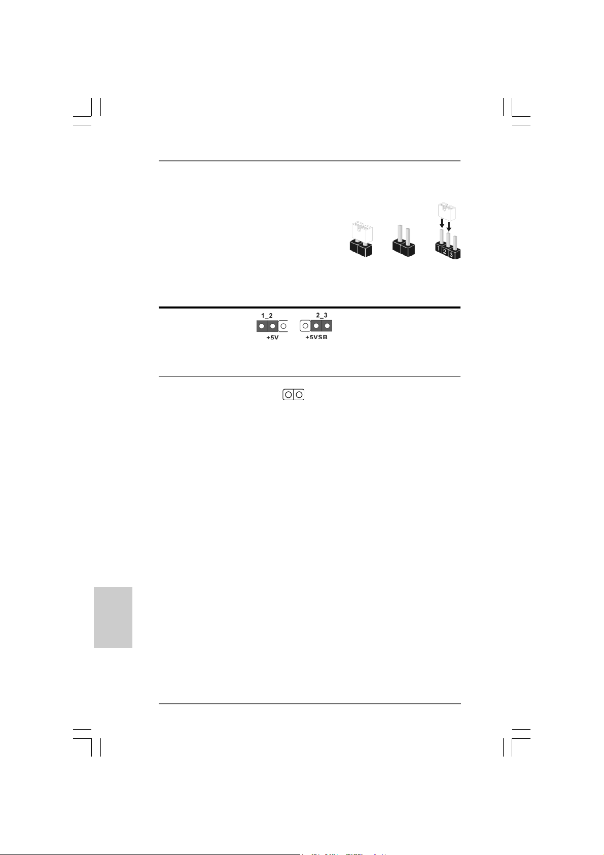
PS2_USB_PWR1 Short pin2, pin3 to enable
(see p.2, No. 1) +5VSB (standby) for PS/2
Note: To select +5VSB, it requires 2 Amp and higher standby current provided
by power supply.
Clear CMOS
(CLRCMOS1, 2-pin jumper)
(see p.2, No. 17)
Note: CLRCMOS1 allows you to clear the data in CMOS. The data in CMOS includes
system setup information such as system password, date, time, and system
setup parameters. To clear and reset the system parameters to default setup,
please turn off the computer and unplug the power cord from the power
supply. After waiting for 15 seconds, use a jumper cap to short 2 pins on
CLRCMOS1 for 5 seconds.
2-pin jumper
Short
or USB wake up events.
Open
English
EnglishEnglish
EnglishEnglish
1414
14
1414
ASRock 4CoreDX90-VSTA Motherboard
Page 15
2.6 Onboard Headers and Connectors2.6 Onboard Headers and Connectors
2.6 Onboard Headers and Connectors
2.6 Onboard Headers and Connectors2.6 Onboard Headers and Connectors
Onboard headers and connectors are NOT jumpers. Do NOT place jumper
caps over these headers and connectors. Placing jumper caps over the
headers and connectors will cause permanent damage of the motherboard!
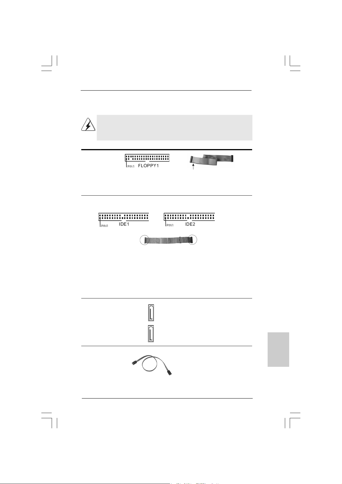
F DD Connector
(33-pin FLOPPY1)
(see p.2, No. 18)
the red-striped side to Pin1
Note: Make sure the red-striped side of the cable is plugged into Pin1 side of the
connector.
Primary IDE Connector (Blue) Secondary IDE Connector (Black)
(39-pin IDE1, see p.2, No. 9) (39-pin IDE2, see p.2, No. 8)
connect the blue end
to the motherboard
80-conductor ATA 66/100/133 cable
connect the black end
to the IDE devices
Note: If you use only one IDE device on this motherboard, please set the IDE
device as “Master”. Please refer to the instruction of your IDE device vendor
for the details. Besides, to optimize compatibility and performance, please
connect your hard disk drive to the primary IDE connector (IDE1, blue) and
CD-ROM to the secondary IDE connector (IDE2, black).
Serial ATA Connectors These two Serial ATA (SATA)
(SAT A1: see p.2, No. 13) connectors support SATA data
(SAT A2: see p.2, No. 12) cables for internal storage
SAT A2
devices. The current SATA
SAT A1
interface allows up to 1.5 Gb/s
data transfer rate.
Serial ATA (SATA) Either end of the SATA data
Data Cable cable can be connected to the
(Optional) SATA hard disk or the SATA
connector on the motherboard.
ASRock 4CoreDX90-VSTA Motherboard
1515
15
1515
EnglishEnglish
EnglishEnglish
English
Page 16
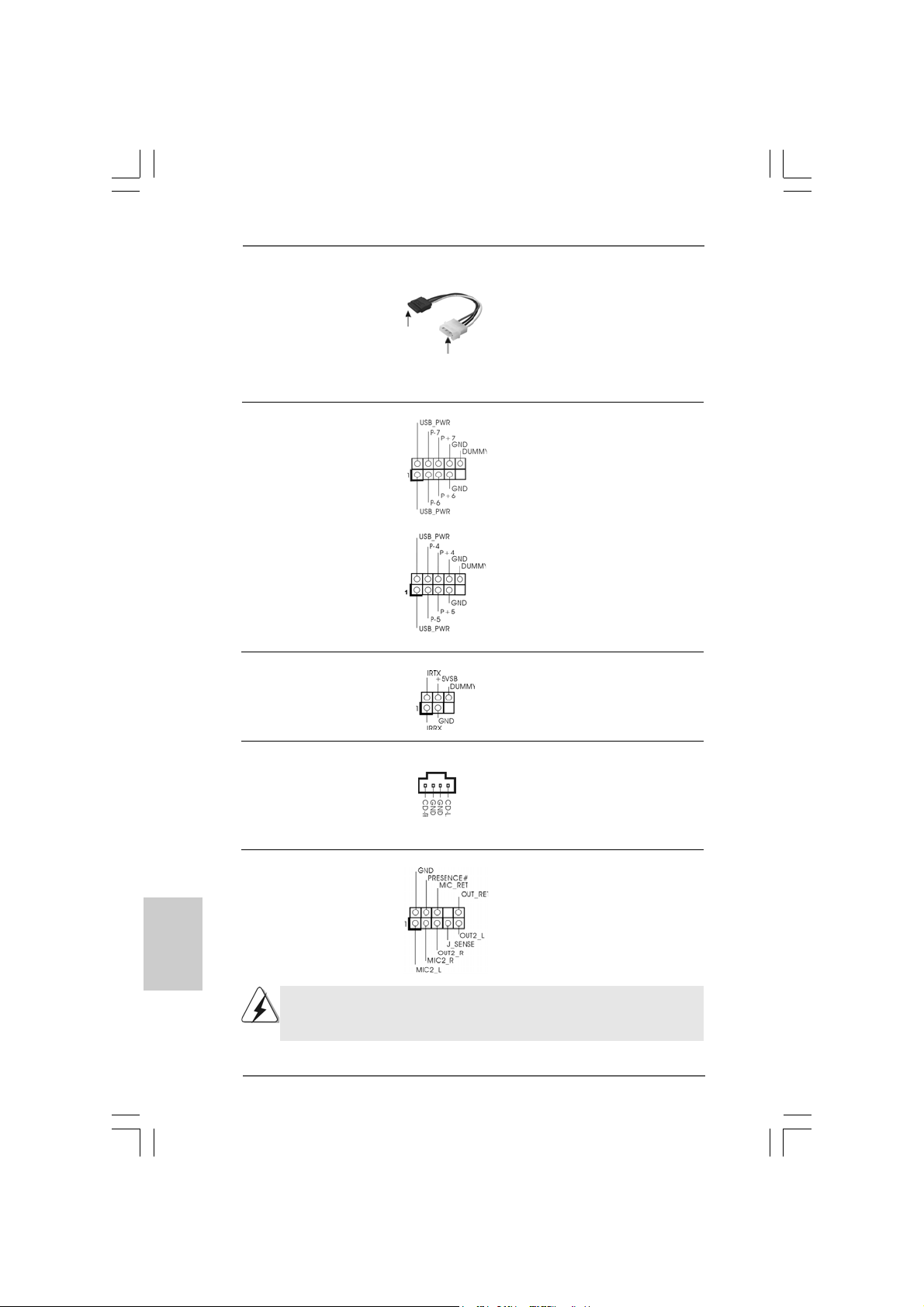
Serial ATA (SATA) Please connect the black end of
Power Cable SATA power cable to the power
(Optional) connector on the drive. Then
connect to the SAT A
HDD power connector
connect to the
power supply
connect the white end of SATA
power cable to the power
connector of the power supply.
USB 2.0 Headers Besides four default USB 2.0
(9-pin USB6_7) ports on the I/O panel, there are
(see p.2 No. 1 1) two USB 2.0 headers on this
motherboard. Each USB 2.0
header cansupport two USB
2.0 ports.
(9-pin USB4_5)
(see p.2 No. 10)
Infrared Module Header This header supports an optional
(5-pin IR1) wireless transmitting and
(see p.2, No. 26) receiving infrared module.
English
EnglishEnglish
EnglishEnglish
1616
16
1616
Internal Audio Connector This connector allows you
(4-pin CD1) to receive stereo audio input
(CD1: see p.2, No. 22) from sound sources such as
CD1
a CD-ROM, D VD-ROM, TV
tuner card, or MPEG card.
Front Panel Audio Header This is an interface for the front
(9-pin HD_AUDIO1) panel audio cable that allows
(see p.2, No. 20) convenient connection and
control of audio devices.
1. High Definition Audio supports Jack Sensing, but the panel wire on the
chassis must support HDA to function correctly. Please follow the
instruction in our manual and chassis manual to install your system.
ASRock 4CoreDX90-VSTA Motherboard
Page 17
2. If you use AC’97 audio panel, please install it to the front panel audio
header as below:
A. Connect Mic_IN (MIC) to MIC2_L.
B. Connect Audio_R (RIN) to OUT2_R and Audio_L (LIN) to OUT2_L.
C. Connect Ground (GND) to Ground (GND).
D. MIC_RET and OUT_RET are for HD audio panel only. You don’t
need to connect them for AC’97 audio panel.
E. Enter BIOS Setup Utility. Enter Advanced Settings, and then select
Chipset Configuration. Set the Front Panel Control option from
[Auto] to [Enabled].
F. Enter Windows system. Click the icon on the lower right hand
taskbar to enter Realtek HD Audio Manager. Click “Audio I/O”, select
“Connector Settings” , choose “Disable front panel jack
detection”, and save the change by clicking “OK”.
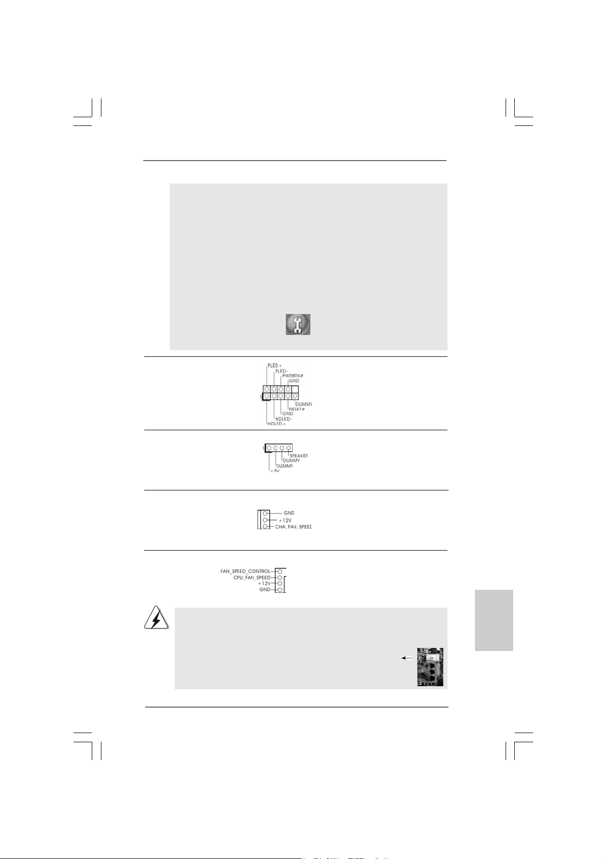
System Panel Header This header accommodates
(9-pin PANEL1) several system front panel
(see p.2, No. 14) functions.
Chassis Speaker Header Please connect the chassis
(4-pin SPEAKER 1) speaker to this header.
(see p.2, No. 16)
Chassis Fan Connector Please connect the chassis fan
(3-pin CHA_FAN1) cable to this connector and
(see p.2, No. 4) match the black wire to the
ground pin.
CPU Fan Connector Please connect the CPU fan
(4-pin CPU_FAN1) cable to this connector and
(see p.2, No. 27) match the black wire to the
Though this motherboard provides 4-Pin CPU fan (Quiet Fan) support, the 3-Pin
CPU fan still can work successfully even without the fan speed control function.
If you plan to connect the 3-Pin CPU fan to the CPU fan connector on this
motherboard, please connect it to Pin 1-3.
4
3
2
1
ground pin.
Pin 1-3 Connected
3-Pin Fan Installation
ASRock 4CoreDX90-VSTA Motherboard
1717
17
1717
EnglishEnglish
EnglishEnglish
English
Page 18
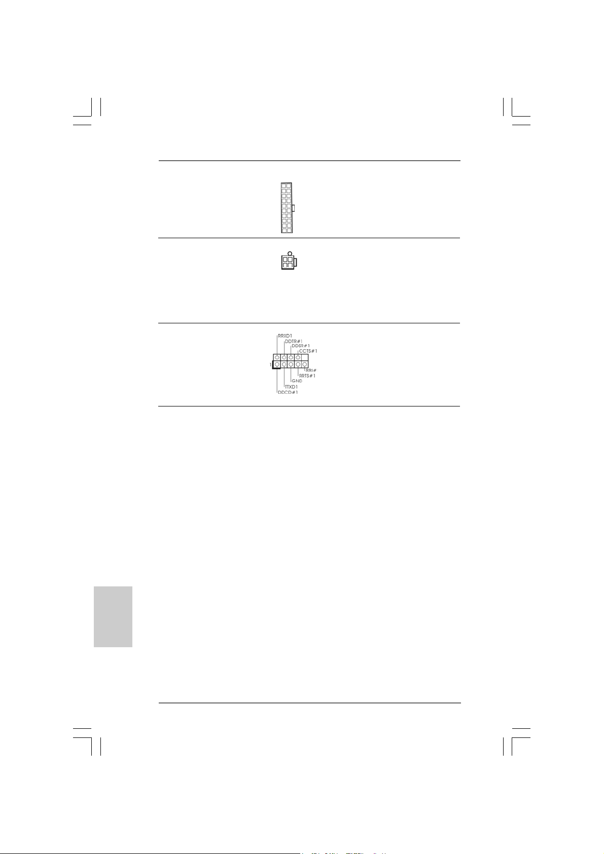
ATX Power Connector Please connect an ATX power
(20-pin ATXPW R1) supply to this connector.
(see p.2, No. 3)
ATX 12V Connector Please note that it is necessary
(4-pin A TX12V1) to connect a power supply with
(see p.2, No. 2) ATX 12V plug to this connector
so that it can provides sufficient
power. Failing to do so will cause
the failure to power up.
Serial port Header This COM1 header
(9-pin COM1) supports a serial port module.
(see p.2 No..25)
English
EnglishEnglish
EnglishEnglish
1818
18
1818
2.7 Serial A2.7 Serial A
2.7 Serial A
2.7 Serial A2.7 Serial A
This motherboard adopts VIA® VT8237A southbridge chipset that supports Serial
ATA (SATA) hard disks and RAID (RAID 0, RAID 1 and JBOD) functions. You may
install SATA hard disks on this motherboard for internal storage devices. This
section will guide you to install the SATA hard disks.
STEP 1: Install the SATA hard disks into the drive bays of your chassis.
STEP 2: Connect the SATA power cable to the SATA hard disk.
STEP 3: Connect one end of the SATA data cable to the motherboard’s SATA
STEP 4: Connect the other end of the SATA data cable to the SATA hard disk.
TT
T
TT
connector.
A (SAA (SA
TT
A) Hard Disks InstallationA) Hard Disks Installation
A (SA
T
A) Hard Disks Installation
A (SAA (SA
TT
A) Hard Disks InstallationA) Hard Disks Installation
ASRock 4CoreDX90-VSTA Motherboard
Page 19
2.8 Hot Plug and Hot Swap F2.8 Hot Plug and Hot Swap F
2.8 Hot Plug and Hot Swap F
2.8 Hot Plug and Hot Swap F2.8 Hot Plug and Hot Swap F
4CoreDX90-VSTA motherboard supports Hot Plug and Hot Swap functions for
SATA Devices .
NOTE
What is Hot Plug Function?
If the SATA HDDs are NOT set for RAID configuration, it is called “Hot
Plug” for the action to insert and remove the SATA HDDs while the system
is still power-on and in working condition.
However, please note that it cannot perform Hot Plug if the OS has been
installed into the SATA HDD.
What is Hot Swap Function?
If SATA HDDs are built as RAID1 then it is called “Hot Swap” for the action
to insert and remove the SATA HDDs while the system is still power-on
and in working condition.
2.92.9
Driver Installation GuideDriver Installation Guide
2.9
Driver Installation Guide
2.92.9
Driver Installation GuideDriver Installation Guide
To install the drivers to your system, please insert the support CD to your optical
drive first. Then, the drivers compatible to your system can be auto-detected and
listed on the support CD driver page. Please follow the order from up to bottom
side to install those required drivers. Therefore, the drivers you install can work
properly.
unctions for SAunctions for SA
unctions for SA
unctions for SAunctions for SA
TT
A HDDsA HDDs
T
A HDDs
TT
A HDDsA HDDs
2.102.10
HDMR Card and Driver Installation HDMR Card and Driver Installation
2.10
HDMR Card and Driver Installation
2.102.10
HDMR Card and Driver Installation HDMR Card and Driver Installation
If you do not insert HDMR card to this motherboard, and you finish installing all
drivers to your system now, but in the future, you plan to use HDMR card function
on this motherboard, please follow the steps below then.
1. Insert HDMR card to HDMR slot on this motherboard. Please make sure that the
HDMR card is completely seated on the slot.
2. Install HDMR card driver from our support CD to your system.
3. Reboot your system.
ASRock 4CoreDX90-VSTA Motherboard
1919
19
1919
EnglishEnglish
EnglishEnglish
English
Page 20
2.112.11
Installing WindowsInstalling Windows
2.11
Installing Windows
2.112.11
Installing WindowsInstalling Windows
/ Vista/ Vista
/ Vista
/ Vista/ Vista
®
2000 / XP / XP 64-bit / Vista 2000 / XP / XP 64-bit / Vista
2000 / XP / XP 64-bit / Vista
2000 / XP / XP 64-bit / Vista 2000 / XP / XP 64-bit / Vista
TMTM
TM
TMTM
64-bit With RAID Functions 64-bit With RAID Functions
64-bit With RAID Functions
64-bit With RAID Functions 64-bit With RAID Functions
TMTM
TM
TMTM
English
EnglishEnglish
EnglishEnglish
The installation procedures for Windows® VistaTM / VistaTM 64-bit are subject to
change. Please visit our website for the updates of Windows® Vista
driver and related information in the future.
If you want to install Windows® 2000, Windows® XP, Windows® XP 64-bit, Windows
VistaTM or Windows® VistaTM 64-bit OS on your SATA HDDs with RAID functions,
please follow below procedures according to the OS you install.
2.11.1 Installing Windows2.11.1 Installing Windows
2.11.1 Installing Windows
2.11.1 Installing Windows2.11.1 Installing Windows
RAID Functions RAID Functions
RAID Functions
RAID Functions RAID Functions
If you want to install Windows® 2000, Windows® XP or Windows® XP 64-bit on your
SATA HDDs with RAID functions, please follow below steps.
STEP 1: Set Up BIOS.
A. Enter BIOS SETUP UTILITY Advanced screen IDE Configuration.
B. Set the “SATA Operation Mode” option to [RAID].
STEP 2: Make a SATA Driver Diskette.
A. Insert the ASRock Support CD into your optical drive to boot your system.
B. During POST at the beginning of system boot-up, press <F11> key, and then a
window for boot devices selection appears. Please select CD-ROM as the boot
device.
C. When you see the message on the screen, “Generate Serial ATA driver diskette
[YN]?”, press <Y>.
D. Then you will see these messages,
Please insert a blank
formatted diskette into floppy
drive A:
press any key to start
Please insert a floppy diskette into the floppy drive, and press any key.
E. The system will start to format the floppy diskette and copy SATA drivers into
the floppy diskette.
STEP 3: Use “RAID Installation Guide” to set RAID configuration.
Before you start to configure RAID function, you need to check the RAID installation
guide in the Support CD for proper configuration. Please refer to the BIOS RAID
installation guide of the document in the following path in the Support CD: .. \ RAID
Installation Guide
®
2000 / XP / XP 64-bit With 2000 / XP / XP 64-bit With
2000 / XP / XP 64-bit With
2000 / XP / XP 64-bit With 2000 / XP / XP 64-bit With
TM
/ VistaTM 64-bit
®
2020
20
2020
ASRock 4CoreDX90-VSTA Motherboard
Page 21
STEP 4: Install Windows® 2000 / Windows® XP / Windows® XP 64-bit OS on
your system.
After step 1, 2, 3, you can start to install Windows® 2000 / Windows® XP / Windows
XP 64-bit OS on your system. At the beginning of Windows® setup, press F6 to install
a third-party RAID driver. When prompted, insert the SATA driver diskette containing
the VIA® RAID driver. After reading the floppy disk, the driver will be presented.
Select the driver to install according to the OS you install.
1. If you install Windows® 2000 / Windows® XP / Windows® XP 64-bit on IDE HDDs and
want to man age (cre ate, convert, delete, or rebuild) RAID functions on SATA HDDs,
please set the RAID configuration by using the Windows RAID installation guide
part of the document in the following path in the Support CD:
.. \ RAID Installation Guide
2. If you want to use “VIA RAID Tool” in Windows® environment, please install SATA
drivers from the Support CD again so that “VIA RAID Tool” will be installed to
your system as well.
®
Vista Vista
Vista
Vista Vista
OS)
TMTM
TM
TMTM
/ Vista / Vista
/ Vista
/ Vista / Vista
TM
64-bit OS)
2.11.2 Installing Windows2.11.2 Installing Windows
2.11.2 Installing Windows
2.11.2 Installing Windows2.11.2 Installing Windows
RAID Functions RAID Functions
RAID Functions
RAID Functions RAID Functions
If you want to install Windows® VistaTM or Windows® VistaTM 64-bit on your SATA
HDDs with RAID functions, please follow below steps.
STEP 1: Set Up BIOS.
A. Enter BIOS SETUP UTILITY Advanced screen IDE Configuration.
B. Set the “SATA Operation Mode” option to [RAID].
STEP 2: Use “RAID Installation Guide” to set RAID configuration.
Before you start to configure RAID function, you need to check the RAID installation
guide in the Support CD for proper configuration. Please refer to the BIOS RAID
installation guide of the document in the following path in the Support CD: .. \ RAID
Installation Guide
STEP 3: Install Windows® VistaTM / Windows® VistaTM 64-bit OS on your
system.
Insert the Windows® VistaTM / Windows® VistaTM 64-bit optical disk into the optical
drive to boot your system, and follow the instruction to install Windows® VistaTM /
Windows® VistaTM 64-bit OS on your system. When you see “Where do you want to
install Windows?” page, please insert the ASRock Support CD into your optical drive,
and click the “Load Driver” button on the left on the bottom to load the VIA® RAID
drivers. VIA® RAID drivers are in the following path in our Support CD:
.. \ I386 \ NT5 (For Windows® Vista
.. \ AMD64 \ 2003x64 (For Windows® Vista
After that, please insert Windows® VistaTM / Windows® VistaTM 64-bit optical disk into
the optical drive again to continue the installation.
®
TM
TMTM
TM
TMTM
64-bit With 64-bit With
64-bit With
64-bit With 64-bit With
EnglishEnglish
EnglishEnglish
English
ASRock 4CoreDX90-VSTA Motherboard
2121
21
2121
Page 22
1. If you install Windows® VistaTM / VistaTM 64-bit on IDE HDDs and want to manage
(create, convert, delete, or rebuild) RAID functions on SATA HDDs,please set the
RAID configuration by using the Windows RAID installation guide part of the
document in the following path in the Support CD:
.. \ RAID Installation Guide
2. If you want to use “VIA RAID Tool” in Windows® environment, please install SATA
drivers from the Support CD again so that “VIA RAID Tool” will be installed to
your system as well.
English
EnglishEnglish
EnglishEnglish
2.122.12
Installing WindowsInstalling Windows
2.12
Installing Windows
2.122.12
Installing WindowsInstalling Windows
TMTM
TM
/ Vista/ Vista
/ Vista
/ Vista/ Vista
If you want to install Windows® 2000, Windows® XP, Windows® XP 64-bit, Windows
VistaTM or Windows® VistaTM 64-bit OS on your SATA HDDs without RAID functions,
please follow below steps.
STEP 1: Set Up BIOS.
A. Enter BIOS SETUP UTILITY Advanced screen IDE Configuration.
B. Set the “SATA Operation Mode” option to [non-RAID].
STEP 2: Install Windows® 2000 / Windows® XP / Windows® XP 64-bit /
After step 1, you can start to install Windows® 2000 / Windows® XP / Windows® XP
64-bit / Windows® VistaTM / Windows® VistaTM 64-bit OS on your system.
2.132.13
Untied Overclocking TUntied Overclocking T
2.13
Untied Overclocking T
2.132.13
Untied Overclocking TUntied Overclocking T
This motherboard supports Untied Overclocking Technology, which means during
overclocking, FSB enjoys better margin due to fixed PCI / PCIE bus. Y ou may set “CPU
Host Frequency” option of BIOS setup to [Auto], which will show you the actual CPU
host frequency in the following item. Therefore, CPU FSB is untied during overclocking,
but PCI / PCIE bus is in the fixed mode so that FSB can operate under a more stable
overclocking environment.
TMTM
64-bit Without RAID Functions 64-bit Without RAID Functions
64-bit Without RAID Functions
64-bit Without RAID Functions 64-bit Without RAID Functions
Windows® VistaTM / Windows® VistaTM 64-bit OS on your system.
Please refer to the warning on page 6 for the possible overclocking risk before
you apply Untied Overclocking Technology.
®
2000 / XP / XP 64-bit / Vista 2000 / XP / XP 64-bit / Vista
2000 / XP / XP 64-bit / Vista
2000 / XP / XP 64-bit / Vista 2000 / XP / XP 64-bit / Vista
echnologyechnology
echnology
echnologyechnology
TMTM
TM
TMTM
®
2222
22
2222
ASRock 4CoreDX90-VSTA Motherboard
Page 23
3. BIOS Information3. BIOS Information
3. BIOS Information
3. BIOS Information3. BIOS Information
The Flash Memory on the motherboard stores BIOS Setup Utility. When you start up
the computer, please press <F2> during the Power-On-Self-Test (POST) to enter
BIOS Setup utility; otherwise, POST continues with its test routines. If you wish to
enter BIOS Setup after POST, please restart the system by pressing <Ctl> + <Alt> +
<Delete>, or pressing the reset button on the system chassis.
The BIOS Setup program is designed to be user-friendly. It is a menu-driven progra m,
which allows you to scroll through its various sub-menus and to select among the
predetermined choices. For the detailed information about BIOS Setup, please refer
to the User Manual (PDF file) contained in the Support CD.
4. Software Suppor4. Software Suppor
4. Software Suppor
4. Software Suppor4. Software Suppor
This motherboard supports various Microsoft® Windows® operating systems: 2000 /
XP / XP 64-bit / VistaTM / Vista
contains necessary drivers and useful utilities that will enhance motherboard features.
To begin using the Support CD, insert the CD into your CD-ROM drive. It will display
the Main Menu automatically if “AUTORUN” is enabled in your computer. If the Main
Menu does not appear automatically, locate and double-click on the file “ASSETUP.
EXE” from the BIN folder in the Support CD to display the menus.
TM
64-bit. The Support CD that ca me with the motherboard
t CD informationt CD information
t CD information
t CD informationt CD information
EnglishEnglish
EnglishEnglish
English
ASRock 4CoreDX90-VSTA Motherboard
2323
23
2323
Page 24
2424
24
2424
ASRock 4CoreDX90-VSTA Motherboard
Page 25
®
® ® ®
®
®
®
®
®
®
ASRock 4CoreDX90-VSTA Motherboard
2525
25
2525
Page 26
2626
26
2626
®
®
ASRock 4CoreDX90-VSTA Motherboard
Page 27
®
®
®
®
®
ASRock 4CoreDX90-VSTA Motherboard
2727
27
2727
Page 28
®
®
®
®
2828
28
2828
ASRock 4CoreDX90-VSTA Motherboard
Page 29
ASRock 4CoreDX90-VSTA Motherboard
2929
29
2929
Page 30
3030
30
3030
ASRock 4CoreDX90-VSTA Motherboard
Page 31

ASRock 4CoreDX90-VSTA Motherboard
3131
31
3131
Page 32

3232
32
3232
ASRock 4CoreDX90-VSTA Motherboard
Page 33

ASRock 4CoreDX90-VSTA Motherboard
3333
33
3333
Page 34

3434
34
3434
ASRock 4CoreDX90-VSTA Motherboard
Page 35

“ ”
SAT A2
SAT A1
ASRock 4CoreDX90-VSTA Motherboard
3535
35
3535
Page 36

3636
36
3636
CD1
ASRock 4CoreDX90-VSTA Motherboard
Page 37

4
3
2
1
ASRock 4CoreDX90-VSTA Motherboard
3737
37
3737
Page 38

®
3838
38
3838
ASRock 4CoreDX90-VSTA Motherboard
Page 39

®
®
®
®
®
®
®
®
®
®
®
ASRock 4CoreDX90-VSTA Motherboard
3939
39
3939
Page 40

®
® ®
® ® ®
®
®
® ®
®
®
®
4040
40
4040
® ®
®
®
®
ASRock 4CoreDX90-VSTA Motherboard
®
®
®
Page 41

® ®
®
®
®
®
®
®
®
®
® ®
®
®
® ®
® ®
®
®
®
®
®
®
ASRock 4CoreDX90-VSTA Motherboard
4141
41
4141
Page 42

® ®
4242
42
4242
ASRock 4CoreDX90-VSTA Motherboard
Page 43

O:
X:
X O O O O O
X O O O O O
ASRock 4CoreDX90-VSTA Motherboard
4343
43
4343
Page 44

1. Introducción1. Introducción
1. Introducción
1. Introducción1. Introducción
Gracias por su compra de ASRock 4CoreDX90-VSTA placa madre, una placa de
confianza producida bajo el control de calidad estricto y persistente. La placa madre
provee realización excelente con un diseño robusto conforme al compromiso de
calidad y resistencia de ASRock.
Esta Guía rápida de instalación contiene una introducción a la placa base y una guía
de instalación paso a paso. Puede encontrar una información más detallada sobre la
placa base en el manual de usuario incluido en el CD de soporte.
Porque las especificaciones de la placa madre y el software de BIOS
podrían ser actualizados, el contenido de este manual puede ser cambiado
sin aviso. En caso de cualquier modificación de este manual, la versión
actualizada estará disponible en el website de ASRock sin previo aviso.
También encontrará las listas de las últimas tarjetas VGA y CPU soportadas
en la página web de ASRock.
Website de ASRock http://www.asrock.com
1.1 Contenido de la caja1.1 Contenido de la caja
1.1 Contenido de la caja
1.1 Contenido de la caja1.1 Contenido de la caja
Placa base ASRock 4CoreDX90-VSTA
(Factor forma Micro ATX: 24,4 cm x 20.8 cm, 9,6” x 8,2”)
Guía de instalación rápida de ASRock 4CoreDX90-VSTA
CD de soporte de ASRock 4CoreDX90-VSTA
Una cinta de datos IDE de conducción 80 Ultra ATA 66/100/133
Una cinta de datos para una unidad de disco de 3,5”
Un Cable de Datos Serial ATA (SATA) (Opcional)
Un cable serie ATA (SATA) de alimentación de disco duro (Opcional)
Una protección HD 8CH I/O
Un soporte de puerto de COM
Español
EspañolEspañol
EspañolEspañol
4444
44
4444
ASRock 4CoreDX90-VSTA Motherboard
Page 45

1.21.2
EspecificaciónEspecificación
1.2
Especificación
1.21.2
EspecificaciónEspecificación
Plataforma - Factor forma Micro ATX: 24,4 cm x 20.8 cm, 9,6” x 8,2”
Procesador - LGA 775 para Intel® CoreTM 2 Extreme / CoreTM 2 Duo /
Pentium® XE / Pentium® D / Pentium® 4 / Celeron® D, compatible
con procesadores Quad Core Kentsfield
- FSB 1066/800/533 MHz
- Admite tecnología Hyper Threading (ver ATENCIÓN 1)
- Admite tecnología de aumento de velocidad liberada
(vea ATENCIÓN 2)
- Admite CPU EM64T
Chipset - North Bridge: VIA® P4M900
- South Bridge: VIA® VT8237A
Memoria - 2 x DDR DIMM slots
- Soporta DDR400/333/266
- Max. 2GB
Amplificador - Stepless control de frecuencia de CPU (vea ATENCIÓN 3)
Híbrido - ASRock U-COP (vea ATENCIÓN 4)
- Protección de Falla de Inicio (B.F.G..)
Ranuras de - 3 x ranuras PCI
Expansión - 1 x ranuras PCI Express x16
- 1 x ranuras HDMR
VGA OnBoard - VIA® Chrome9 HC
- Sombreador de Píxeles 2.0, VGA DirectX 9.0
- 256MB de Memoria máxima compartida
Audio - Sonido HD de Nivel Basic 7.1 Canales Windows® Vista
(Códec de sonido ALC883)
LAN - VIA® PHY VT6103
- Velocidad: 10/100 Ethernet
- Soporta Wake-On-LAN
Entrada/Salida HD 8CH I/O
de Panel - 1 x puerto de ratón PS/2
Trasero - 1 x puerto de teclado PS/2
- 1 x puerto VGA
- 1 x puerto paralelo: soporta ECP/EPP
- 4 x puertos USB 2.0 predeterminados
- 1 x puerto RJ-45
- Conexión de audio: Altavoz lateral / Altavoz trasero /
Central/Bajos / Entrada de línea / Altavoz frontal / Micrófono
(ver ATENCIÓN 5)
TM
EspañolEspañol
EspañolEspañol
Español
ASRock 4CoreDX90-VSTA Motherboard
4545
45
4545
Page 46

Español
EspañolEspañol
EspañolEspañol
Conectores - 2 x conexiones SATA, admiten una velocidad de
transferencia de datos de hasta 1,5Gb/s, soporta las
funciones RAID (RAID 0, RAID 1 y JBOD) y “Conexión
en caliente”
- 2 x ATA133 conexiones IDE
(admite hasta 4 dispositivos IDE)
- 1 x puerto Floppy
- 1 x cabezal de Módulo Infrarrojos
- 1 x En-tête de port COM
- Conector del ventilador del CPU/chasis
- 20-pin cabezal de alimentación ATX
- 4-pin conector de ATX 12V power
- Conector de Audio Interno
- Conector de audio de panel frontal
- 2 x Cabezal USB 2.0 (admite 4 puertos USB 2.0 adicionales)
(vea ATENCIÓN 6)
BIOS - 4Mb AMI BIOS
- AMI legal BIOS
- Soporta “Plug and Play”
- ACPI 1.1 compliance wake up events
- Soporta “jumper free setup”
- Soporta SMBIOS 2.3.1
CD de soport - Controladores, Utilerías, Software de Anti Virus
(Versión de prueba)
Monitor Hardware - Sensibilidad a la temperatura del procesador
- Sensibilidad a la temperatura de la placa madre
- Taquímetros de los ventiladores del procesador y del
procesador
- Taquímetros de los ventiladores del procesador y del chasis
- Ventilador silencioso para procesador
- Monitor de Voltaje: +12V, +5V, +3.3V, Vcore
OS - En conformidad con Microsoft® Windows® 2000 / XP /
XP 64 bits / VistaTM / VistaTM 64 bits (vea ATENCIÓN 7)
Certificaciones - FCC, CE, WHQL
4646
46
4646
ASRock 4CoreDX90-VSTA Motherboard
Page 47

AD VERTENCIA
Tenga en cuenta que hay un cierto riesgo implícito en las operaciones de aumento de la
velocidad del reloj, incluido el ajuste del BIOS, aplicando la tecnología de aumento de
velocidad liberada o utilizando las herramientas de aumento de velocidad de otros
fabricantes. El aumento de la velocidad puede afectar a la estabilidad del sistema e,
incluso, dañar los componentes y dispositivos del sistema. Esta operación se debe
realizar bajo su propia responsabilidad y Ud. debe asumir los costos. No asumimos
ninguna responsabilidad por los posibles daños causados por el aumento de la velocidad
del reloj.
ATENCIÓN!
1. Por favor consulte página 33 del Manual del Usuario en el soporte CD
sobre la configuración de Hyper-Threading Te chnology.
2. Esta placa base admite la tecnología de aumento de velocidad liberada.
Por favor lea “Tecnología de Forzado de Reloj (Overclocking) no
relacionado” en la página 64 para obtener detalles.
3. Aunque esta placa base ofrece un control complete, no es recomendable
forzar la velocidad. Las frecuencias de bus de la CPU distintas a las
recomendada s pueden causar ine sta bilida d en el siste ma o dañar la CPU.
4. Cuando la temperatura de CPU está sobre-elevada, el sistema va a
apagarse automaticamente. Antes de reanudar el sistema, compruebe si
el ventilador de la CPU de la placa base funciona apropiadamente y
desconecte el cable de alimentación, a continuación, vuelva a
conectarlo. Para mejorar la disipación de calor, acuérdese de aplicar
thermal grease entre el procesador y el disipador de calor cuando usted
instala el sistema de PC.
5. Para la entrada de micrófono, esta placa madre ofrece soporte para
modos estéreo y mono. Para salida de audio, este placa madre ofrece
soporte para modos de 2 canales, 4 canales, 6 canales y 8 canales.
Consulte la tabla en la página 3 para una conexión correcta.
6. Power Management para USB 2.0 funciona bien bajo Microsoft
Windows® VistaTM 64 bits / VistaTM / XP 64 bits / XP SP1; SP2/2000 SP4.
7. El controlador para Microsoft® Windows® VistaTM / VistaTM 64 bits sigue en
proceso de actualiza ción. Siempre que tenga mos el controlador más reciente,
lo actualizaremos en nuestro sitio Web en el futuro. Visite nuestro sitio
Web si desea obtener el controlador para Microsoft® Windows® VistaTM /
VistaTM 64 bits así como la información relacionada.
Sitio Web de ASRock: http://www.asrock.com
®
EspañolEspañol
EspañolEspañol
Español
ASRock 4CoreDX90-VSTA Motherboard
4747
47
4747
Page 48

1.31.3
TT
1.3
1.31.3
abla de requisitos mínimos de hardware paraabla de requisitos mínimos de hardware para
T
abla de requisitos mínimos de hardware para
TT
abla de requisitos mínimos de hardware paraabla de requisitos mínimos de hardware para
®®
®
WindowsWindows
Windows
WindowsWindows
Para usuarios e integradores de sistemas que adquieran nuestra placa
base y pretendan someterla al logotipo de Windows® VistaTM Basic,
consulte la tabla siguiente para obtener información sobre los requisitos
mínimos de hardware.
Procesador Celeron D 326
Memoria 512 MB de un solo canal*
VGA DX9.0 con controlador W DDM
®®
Logotipo de Vista Logotipo de Vista
Logotipo de Vista
Logotipo de Vista Logotipo de Vista
TMTM
TM
TMTM
Basic Basic
Basic
Basic Basic
Español
EspañolEspañol
EspañolEspañol
* Si utiliza una tarjeta gráfica VGA en placa, posee una memoria total en su sistema de
512 MB, y desea pasar la prueba de certificación del logotipo de Windows® Vista
Basic, ajuste el tamaño de memoria compartida de su VGA en placa a 64MB. Si utiliza
una tarjeta VGA integrada con un tamaño de memoria del sistema superior a 512 MB
y pretende presentar el logotipo de Windows® VistaTM Basic, ajuste el tamaño de la
memoria compartida de la tarjeta VGA a 128 MB como mínimo.
TM
4848
48
4848
ASRock 4CoreDX90-VSTA Motherboard
Page 49

2. Instalación2. Instalación
2. Instalación
2. Instalación2. Instalación
Precaución de Pre-instalaciónPrecaución de Pre-instalación
Precaución de Pre-instalación
Precaución de Pre-instalaciónPrecaución de Pre-instalación
Tenga en cuenta las precauciones siguientes antes de instalar los
componentes de la placa base o cambiar cualquier configuración de la
placa base.
1. Desconecte el cable de electricidad antes de tocar cualquier
componente.
2. Para prevenir daño del componente de la placa madre por
electricidad estástica, NUNCA ponga su placa madre dire ctamente
sobre la alfombra y otros por el estilo. Póngase la pulsera antiestástica o toquelo a cualquier objecto de tierra, por ejémplo como
el cabinete de su computador, para liberar cualquiera carga
estástica.
3. Tome componentes por la margen y no toque los ICs.
4. Ponga cualquier componente deslocalizado sobre la bolsa antiestástica que viene con la placa madre.
5. Al colocar los tornillos en sus agujeros para fijar la placa madre en
el chasis, no los apriete demasiado. Eso podría dañar la placa
madre.
2.1 Instalación de Procesador2.1 Instalación de Procesador
2.1 Instalación de Procesador
2.1 Instalación de Procesador2.1 Instalación de Procesador
Para la instalación de la CPU Intel de
775 agujas, siga los siguientes pasos.
(Placa de carga)
(Matriz de contacto)
(Cuerpo del socket)
Introducción al socket de 775 agujas
ASRock 4CoreDX90-VSTA Motherboard
4949
49
4949
EspañolEspañol
EspañolEspañol
Español
Page 50

Antes de insertar la CPU de 775 agujas en el socket, compruebe
que la superficie de la CPU se encuentra limpia y no hay ninguna
aguja torcida en el socket. No introduzca la CPU en el socket por la
fuerza si se produce la situación anterior. Si lo hace, puede producir
daños graves en la CPU.
Paso 1. Abra el socket:
Paso 1-1. Suelte la palanca presionando
hacia abajo y hacia afuera en el
gancho para retirar la lengüeta de
retención.
Paso 1-2. Gire la palanca de carga hasta la
posición de apertura completa,
135 grados aproximadamente.
Paso 1-3. Gire la placa de carga hasta la
posición de apertura completa,
aproximadamente 100 grados.
Paso 2. Inserte la CPU de 775 agujas:
Paso 2-1. Sostenga la CPU por los bordes
marcados con líneas negras.
Línea negra
Línea negra
Español
EspañolEspañol
EspañolEspañol
5050
50
5050
aguja 1
Muesca de
orientación
Paso 2-2. Sitúe el paquete con el IHS
(Integrated Heat Sink) mirando
hacia arriba. Busque la aguja 1 y
las dos muescas de orientación.
aguja 1
Muesca de
orientación
CPU de 775 agujas
Para insertarla correctamente, asegúrese de que las dos muescas
de orientación de la CPU coinciden con las teclas de alineación del
socket.
T ecla de alineación
Socket de 775 agujas
ASRock 4CoreDX90-VSTA Motherboard
Te cla de alineación
Page 51

Step 2-3. Coloque con cuidado la CPU en el
socket con un movimiento
totalmente vertical.
Step 2-4. Compruebe que la CPU se
encuentra en el socket y la
orientación coincide con la
indicada por las muescas.
Paso 3. Retire la cubierta PnP (Pick and Place):
Utilice los dedos índice y pulgar de su mano
izquierda para sostener el borde de la placa
de carga, introduzca el pulgar de su mano
derecha debajo de la cubierta PnP y
despéguela del socket mientras presiona en
el centro de la cubierta PnP para ayudar a
retirarla.
1. Se recomienda que utilice la lengüeta de la cubierta para retirarla,
evitando arrancar la cubierta PnP.
2. Esta cobertura debe colocarse si la placa base vuelve tras ser
reparada.
Paso 4. Cierre el socket:
Paso 4-1. Gire la placa de carga hacia el IHS.
Paso 4-2. Accione la palanca de carga
mientras presiona ligeramente en
la placa de carga.
Paso 4-3. Fije la palanca de carga con la
lengüeta de la placa de carga
debajo de la lengüeta de retención
de la palanca de carga.
2.22.2
Instalación del ventilador y el disipador de la CPUInstalación del ventilador y el disipador de la CPU
2.2
Instalación del ventilador y el disipador de la CPU
2.22.2
Instalación del ventilador y el disipador de la CPUInstalación del ventilador y el disipador de la CPU
Para una correcta instalación, consulte los manuales de instrucciones del
ventilador y el disipador de la CPU.
A continuación se ofrece un ejemplo para ilustrar la instalación del disipador para
la CPU de 775 agujas.
Paso 1. Aplique el material termal de interfaz en el
centro del IHS de la superficie del socket.
ASRock 4CoreDX90-VSTA Motherboard
(Aplique el material termal de interfaz)
5151
51
5151
EspañolEspañol
EspañolEspañol
Español
Page 52

Paso 2. Coloque el disipador en el socket. Asegúrese
de que los cables del ventilador están
orientados hacia el lado más cercano del
conector del ventilador de la CPU en la placa
madre (CPU_FAN1, ver página 2, nº 4).
(Cables del ventilador en el lado más
próximo al cabezal de la placa madre)
Paso 3. Alinee los cierres con los agujeros de la
placa madre.
Paso 4. Gire el cierre en la dirección de las agujas del
reloj y, a continuación, presione las cubiertas
del cierre con el dedo pulgar para instalar y
bloquear. Repita el proceso con los cierres
restantes.
Si presiona los cierres sin girarlos en el sentido de las agujas del
reloj, el disipador no se podrá fijar a la placa madre.
Paso 5. Conecte el cabezal del ventilador con el
conector del ventilador de la CPU en la placa
madre.
Paso 6. Fije el cable que sobre con un lazo para
asegurarse de que el cable no interfiere en el
funcionamiento del ventilador y tampoco entra
en contacto con otros componentes.
(Ranuras de cierre orienta da s al exterior)
1 x PCI Express Gra
Español
EspañolEspañol
EspañolEspañol
5252
52
5252
ASRock 4CoreDX90-VSTA Motherboard
Page 53

2.3 Instalación de Memoria2.3 Instalación de Memoria
2.3 Instalación de Memoria
2.3 Instalación de Memoria2.3 Instalación de Memoria
La placa base 4CoreDX90-VSTA proporciona dos zócalos DIMM DDR (Doble
velocidad de datos) de 184 contactos
Asegúrese de desconectar la fuente de alimentación antes de añadir o
retirar módulos DIMM o componentes del sistema.
Instalación de una DIMMInstalación de una DIMM
Instalación de una DIMM
Instalación de una DIMMInstalación de una DIMM
Paso 1. Empuje los clips blancos de retención por el extremo de cada lado de la
ranura de memoria.
Paso 2. Encaje la muesca del DIMM hacia la cumbrera de la ranura.
DIMM ajusta solamente en una dirección. Si fuerza la DIMM en la ranura
con una orientación incorrecta, provocará daños permanentes en la
placa base y en la DIMM.
Paso 3. Inserte la DIMM con firmeza dentro de la ranura hasta que los clips de
sujeción de ambos lados queden completamente introducidos en su sitio y
la DIMM se haya asentado apropiadamente.
ASRock 4CoreDX90-VSTA Motherboard
5353
53
5353
EspañolEspañol
EspañolEspañol
Español
Page 54

2.42.4
Ranuras de ExpansiónRanuras de Expansión
2.4
Ranuras de Expansión
2.42.4
Ranuras de ExpansiónRanuras de Expansión
(ranuras PCI, ranuras HDMR y ranuras PCI Express)(ranuras PCI, ranuras HDMR y ranuras PCI Express)
(ranuras PCI, ranuras HDMR y ranuras PCI Express)
(ranuras PCI, ranuras HDMR y ranuras PCI Express)(ranuras PCI, ranuras HDMR y ranuras PCI Express)
La placa madre 4CoreDX90-VSTA cuenta con 3 ranuras PCI, 1 ranuras HDMR y 1
ranuras PCI Express.
Ranura PCI: Para instalar tarjetas de expansión que tienen 32-bit Interface PCI.
Ranura HDM R:Ranura HDMR se utilizar para insertar una tarjeta ASRock HDMR
y funcionalidad de módem v.92.
Ranura PCI Express: PCIE1 (ranura PCIE x16) se utiliza para tarjetas PCI Ex-
press con tarjetas gráficas con una anchura de 16
carriles.
Si instala la tarjeta complemento VGA PCI Express para PCIE1 (ranura PCIE
x16), se desactivará VGA en placa.
Español
EspañolEspañol
EspañolEspañol
Instalación de TInstalación de T
Instalación de T
Instalación de TInstalación de T
Paso 1. Antes de instalar la tarjeta de expansión, asegúrese de que la fuente de
alimentación está apagada o el ca ble de alimentación desconectado. Le a la
documentación que acompaña a la tarjeta de expansión y realice las
configuraciones de hardware necesarias para la tarjeta antes de iniciar la
instalación.
Paso 2. Quite la tapa que corresponde a la ranura que desea utilizar.
Paso 3. Encaje el conector de la tarjeta a la ranura. Empuje firmemente la tarjeta en
la ranura.
Paso 4. Asegure la tarjeta con tornillos.
arjetas de Expansiónarjetas de Expansión
arjetas de Expansión
arjetas de Expansiónarjetas de Expansión
..
.
..
5454
54
5454
ASRock 4CoreDX90-VSTA Motherboard
Page 55

2.5 Configuración de los Jumpers2.5 Configuración de los Jumpers
2.5 Configuración de los Jumpers
2.5 Configuración de los Jumpers2.5 Configuración de los Jumpers
La ilustración muestra como los jumpers son
configurados. Cuando haya un jumper-cap
sobre los pins, se dice gue el jumper está
“Short”. No habiendo jumper cap sobre los
pins, el jumper está “Open”. La ilustración
muesta un jumper de 3 pins cuyo pin 1 y pin
2 están “Short”.
Jumper Setting Descripción
PS2_USB_PWR1 Ponga en cortocircuito pin 2,
(ver p.2 N. 1) pin 3 para habilitar +5VSB
Atención: Para elegir +5VSB, se necesita corriente mas que 2 Amp proveida por la
fuente de electricidad.
Limpiar CMOS
(CLRCMOS1, jumper de 2 pins)
(ver p.2, N. 17)
Atención: CLRCMOS1 permite que Usted limpie los datos en CMOS. Los datos en
CMOS incluyen informa ciones de la configuración del sistema, tales como
la contraseña del sistema, fecha, tie mpo, y parámetros de la conf iguración
del sistema. Para limpiar y reconfigurar los parametros del sistema a la
configuración de la fábrica, por favor apague el computador y desconecte
el cable de la fuente de electricidad, ponga en cortocircuito los pins de
CLRCMOS1 por más que 5 segundos usando un jumper cap.
jumper de 2 pins
Short Open
(standby) para PS/2 o U S B
wake up events.
ASRock 4CoreDX90-VSTA Motherboard
5555
55
5555
EspañolEspañol
EspañolEspañol
Español
Page 56

2.6 Cabezales y Conectores en Placas2.6 Cabezales y Conectores en Placas
2.6 Cabezales y Conectores en Placas
2.6 Cabezales y Conectores en Placas2.6 Cabezales y Conectores en Placas
Los conectores y cabezales en placa NO son puentes. NO coloque las
cubiertas de los puentes sobre estos cabezales y conectores. El colocar
cubiertas de puentes sobre los conectores y cabezales provocará un
daño permanente en la pla ca base.
Conector de disquetera
(33-pin FLOPPY1)
(ver p.2 N. 18)
la banda roja debe quedar en
el mismo lado que el contacto 1
Atención: Asegúrese que la banda roja del cable queda situado en el mismo lado que
el contacto 1 de la conexión.
IDE conector primario (azul) IDE conector secundario (negra)
(39-pin IDE1, ver p.2 N. 9) (39-pin IDE2, ver p.2 N. 8)
Conector azul Conector negro
a placa madre a aparato IDE
Cable ATA 66/100/133 de conducción 80
Atención: Si utiliza solamente un dispositivo IDE en esta placa base, configúrelo
como “maestro”. Consulte las instrucciones del distribuidor del dispositivo
IDE para conocer los detalles. Además, para optimizar la compatibilidad y
el rendimiento, conecte el disco duro a la conexión IDE primaria,
(IDE1, azul) y el CD-ROM a la conexión IDE secundaria (IDE2, negra).
Español
EspañolEspañol
EspañolEspañol
5656
56
5656
Conexiones de serie ATA Estas dos conexiones de serie
(SAT A1: ver p.2, No. 13) ATA (SATA) admiten cables
(SAT A2: ver p.2, No. 12) SATA para dispositivos de
SAT A2
almacenamiento internos. La
interfaz SATA actual permite
SAT A1
una velocidad de transferencia
de 1.5 Gb/s.
Cable de datos de Ambos extremos del cable
serie ATA (SATA) pueden conectarse al disco
(Opcional) duro SATA o la conexión de la
placa base.
ASRock 4CoreDX90-VSTA Motherboard
Page 57

Cable de alimenta ción Conecte el extremo negro del
de serie ATA (SATA) cable de SATA al conector de
(Opcional) energía de la unidad. A
Conectar a la conexión de
alimentación del disco
duro SAT A
Conectar a la fuente
de alimentación
continuación, conecte el
extremo blanco del cable de
alimentación SATA a la
conexión de alimentación de la
fuente de alimentación.
Cabezal USB 2.0 Además de cuatro puertos
(9-pin USB6_7) USB 2.0 predeterminados en el
(ver p.2, No. 1 1) panel de E/S, hay dos bases
de conexiones USB 2.0 en
esta placa base. Cada una de
estas bases de conexiones
(9-pin USB4_5) admite dos puertos USB 2.0.
(ver p.2, No. 10)
Conector de módulo Infrared Soporta módulo Infrared de
(5-pin IR1) transmisión y recepción
(ver p.2, N. 26) wireless.
Conector de audio interno Permite recepción de input
(4-pin CD1) audio de fuente sónica como CD-
(CD1: ver p.2, N. 22) ROM, DV D-ROM TV tuner, o
CD1
tarjeta MPEG.
Conector de audio de panel Este es una interface para
frontal cable de audio de panel frontal
(9-pin HD_AUDIO1) que permite conexión y control
(vea p.2, No. 20) conveniente de apparatos de
Audio.
ASRock 4CoreDX90-VSTA Motherboard
5757
57
5757
EspañolEspañol
EspañolEspañol
Español
Page 58

1. El Audio de Alta Definición soporta la detección de conector, pero el cable
de panel en el chasis debe soportar HDA para operar correctamente. Por
favor, siga las instrucciones en nuestro manual y en el manual de chasis
para instalar su sistema.
2. Si utiliza el panel de sonido AC’97, instálelo en la cabecera de sonido del
panel frontal de la siguiente manera:
A. Conecte Mic_IN (MIC) a MIC2_L.
B. Conecte Audio_R (RIN) a OUT2_R y Audio_L (LIN) en OUT2_L.
C. Conecte Ground (GND) a Ground (GND).
D. MIC_RET y OUT_RET son sólo para el panel de sonido HD. No
necesitará conectarlos al panel de sonido AC’97.
E. Entre en la Utilidad de configuración del BIOS Entre en Configuración
avanzada y, a continuación, seleccione Configuración del conjunto de
chips. En el panel de control frontal cambie la opción [Automático] a
[Habilitado].
F. Entre en el sistema Windows. Haga clic en el icono de la barra de tareas
situada en la parte inferior derecha para entrar en el Administrador de
audio HD Realtek. Haga clic en “E/S de audio”, seleccione “Configuración
de conectores” , elija “Deshabilitar la detección del conector del
panel frontal” y guarde el cambio haciendo clic en “Aceptar”.
Conector del panel del systema Este conector acomoda varias
(9-pin PANEL1) funciones de panel frontal del
(ver p.2, N. 14) systema.
Español
EspañolEspañol
EspañolEspañol
5858
58
5858
Cabezal del altavoz del chasis Conecte el altavoz del chasis a
(4-pin SPEAKER1) su cabezal.
(ver p.2, N. 16)
Conector del ventilador Conecte el cable del ventilador
del chasis del chasis a este conector y
(3-pin CHA_FAN1) haga coincidir el cable negro
(ver p.2, N. 4) con el conector de tierra.
Conector del ventilador Conecte el cable del ventilador
de la CPU de la CPU a este conector y
(4-pin CPU_FAN1) haga coincidir el cable negro
(ver p.2, N. 27) con el conector de tierra.
4
3
2
1
ASRock 4CoreDX90-VSTA Motherboard
Page 59

Aunque esta placa base proporciona compatibilidad para un ventilador
(silencioso) de procesador de 4 contactos, el ventilador de procesador de 3
contactos seguirá funcionando correctamente incluso sin la función de control
de velocidad del ventilador. Si pretende enchufar el ventilador de procesador
de 3 contactos en el conector del ventilador de procesador de esta placa base,
conéctelo al contacto 1-3.
Instalación del ventilador de 3 contactos
Contacto 1-3 conectado
Cabezal de alimentación ATX Conecte la fuente de
(20-pin ATXPW R1) alimentación ATX a su cabezal.
(ver p.2, N. 3)
Conector de ATX 12V power Tenga en cuenta que es
(4-pin A TX12V1) necesario conectar este
(ver p.2, N. 2) conector a una toma de corriente
con el enchufe ATX 12V, de
modo que proporcione suficiente
electricidad. De lo contrario no
se podrá encender.
Cabezal del puerto COM Este cabezal del puerto COM
(9-pin COM1) se utiliza para admitir un
(vea p.2, N. 25) módulo de puerto COM.
ASRock 4CoreDX90-VSTA Motherboard
5959
59
5959
EspañolEspañol
EspañolEspañol
Español
Page 60

2.72.7
Instalación de discos duro AInstalación de discos duro A
2.7
Instalación de discos duro A
2.72.7
Instalación de discos duro AInstalación de discos duro A
Configuración RAIDConfiguración RAID
Configuración RAID
Configuración RAIDConfiguración RAID
Esta placa base adopta el chipset VIA® VT8237A que soporta discos duros ATA
Serie (SATA) y funciones RAID (RAID 0, RAID 1 y JBOD). Puede instalar discos
duros SATA en esta placa base como dispositivos de almacenamiento interno. Esta
sección le guiará a través del proceso de instalación de los discos duros SATA.
PASO 1: Instale los discos duros SATA dentro de las bahías para unidades del
chasis.
PASO 2: Conecte el cable de alimentación SATA al disco duro SATA.
PASO 3: Conecte un extremo del cable de datos SATA al conector SATA de la
placa base.
PASO 4: Conecte el otro extremo del cable de datos SATA al disco duro SATA.
2.82.8
Función de conexión y cambio en caliente paraFunción de conexión y cambio en caliente para
2.8
Función de conexión y cambio en caliente para
2.82.8
Función de conexión y cambio en caliente paraFunción de conexión y cambio en caliente para
HDDs SAHDDs SA
HDDs SA
HDDs SAHDDs SA
La placa base 4CoreDx90-VSTA soporta la función de conexión en caliente para
Dispositivos SATA.
TT
AA
T
A
TT
AA
NOTA
¿Qué es la función de conexión en caliente?
Si los HDDs SATA no están fijados para su configuración RAID, se
llama “Conexión en caliente” a la acción de insertar y quitar los HDDs
SATA mientras el sistema está conectado y en condiciones de
funcionamiento.
TT
A serie (SAA serie (SA
T
A serie (SA
TT
A serie (SAA serie (SA
TT
A) /A) /
T
A) /
TT
A) /A) /
Español
EspañolEspañol
EspañolEspañol
6060
60
6060
¿Qué es la función de cambio en caliente?
Si los HDDs SATA están configurados como RAID1 se llama “Cambio
en caliente” a la acción de insertar y quitar los HDDs SATA mientras
el sistema está conectado y en condiciones de funcionamiento.
2.92.9
Guía de instalación del controladorGuía de instalación del controlador
2.9
Guía de instalación del controlador
2.92.9
Guía de instalación del controladorGuía de instalación del controlador
Para instalar los controladores en el sistema, inserte en primer lugar el CD de
soporte en la unidad óptica. A continuación, se detectarán automáticamente los
controladores compatibles con el sistema y se mostrarán en la página de
controladores de CD compatibles. Siga el orden de arriba a abajo para instalar los
controladores requeridos. Los controladores que instale pueden funcionar
correctamente.
ASRock 4CoreDX90-VSTA Motherboard
Page 61

2.102.10
TT
2.10
2.102.10
Si no inserta la tarjeta HDMR para esta placa base y termina de instalar todos los
controladores para el sistema ahora, pero en un futuro, pretende utilizar la
función de la tarjeta HDMR en esta placa base, siga los pasos que se indican a
continuación.
1. Inserte la tarjeta HDMR en la ranura HDMR de esta placa base. Asegúrese de
que la tarjeta HDMR está completamente asentada en la ranura.
2. Instale el controlador de la tarjeta HDMR (que encontrará en nuestro CD de
soporte) en el sistema.
3. Reinicie el equipo.
2.112.11
2.11
2.112.11
arjeta HDMR e instalación del controladorarjeta HDMR e instalación del controlador
T
arjeta HDMR e instalación del controlador
TT
arjeta HDMR e instalación del controladorarjeta HDMR e instalación del controlador
®®
®
Instalación de Windows Instalación de Windows
Instalación de Windows
Instalación de Windows Instalación de Windows
TM TM
TM
TM TM
Vista Vista
Vista
Vista Vista
/ Vista/ Vista
/ Vista
/ Vista/ Vista
Los procedimientos de instalación para Windows® VistaTM / VistaTM 64 bits se
encuentran sujetos a cambios. Visite nuestra página web y descargue las
actualizaciones del controlador para Windows® VistaTM / VistaTM 64 bits y la
información relacionada.
TMTM
TM
TMTM
64 bits con funciones RAID 64 bits con funciones RAID
64 bits con funciones RAID
64 bits con funciones RAID 64 bits con funciones RAID
®®
2000 / XP / XP 64 bits / 2000 / XP / XP 64 bits /
2000 / XP / XP 64 bits /
2000 / XP / XP 64 bits / 2000 / XP / XP 64 bits /
Si desea instalar Windows® 2000, Windows® XP, Windows® XP 64 bits, Windows
VistaTM, Windows® VistaTM 64 bits en sus HDDs SATA con funciones RAID, siga
los procedimientos que se indican a continuación en función del sistema operativo
que tenga instalado.
®®
®
2.11.1 Instalación de Windows2.11.1 Instalación de Windows
2.11.1 Instalación de Windows
2.11.1 Instalación de Windows2.11.1 Instalación de Windows
con funciones RAID con funciones RAID
con funciones RAID
con funciones RAID con funciones RAID
Si desea instalar el sistema operativo Windows® 2000 / Windows® XP / Windows
XP 64 bits en su sistema con funciones RAID, siga los pasos siguientes.
PASO 1: Configure BIOS.
A. Entre a la Utilidad de configuración de BIOS pantalla de Avanzada
Configuración IDE.
B. Establezca la opción “SATA Operation Mode”(Modo de funcionamiento
SATA) en [RAID].
PASO 2: Haga un Disquete de Controlador SATA.
A. Inserte el CD de soporte de ASRock en la unidad óptica de la unidad para
iniciar el sistema. (NO inserte ningún disquete en la unidad de disco en este
momento)
B. Durante la comprobación inicial (POST) del sistema, pulse la tecla <F11> y
aparecerá una ventana de selección de los dispositivos de inicio. Seleccione
ASRock 4CoreDX90-VSTA Motherboard
®®
2000 / XP / XP 64 bits 2000 / XP / XP 64 bits
2000 / XP / XP 64 bits
2000 / XP / XP 64 bits 2000 / XP / XP 64 bits
®
®
EspañolEspañol
EspañolEspañol
Español
6161
61
6161
Page 62

el CD-ROM como unidad de inicio.
C. Cuando vea en pantalla el mensaje: “Generate Serial ATA driver diskette [Y/
N]? (¿Desea generar un disquete de controlador de serie A TA?)”, pulse <Y>.
D. A continuación podrá ver los siguientes mensajes:
Please insert a blank
formatted diskette into floppy
drive A:
press any key to start
(Inserte un disco flexible flormateado en la unidad de disco
A: y pulse cualquier tecla para comenzar)
Por favor, inserte un disco flexible en la unidad de disco y presione
cualquier tecla.
E. El sistema comenzará a formatear el disquete y copiar controladores SATA
en el disquete.
PASO 3: Use la “RAID Installation Guide” para establecer la
configuración RAID.
Antes de configurar la función RAID, es necesario consultar la guía de instalación
RAID incluida en el CD de soporte, para obtener información sobre cómo realizar la
instalación correctamente. Consulte la parte de la guía de instalación BIOS RAID del
documento que se encuentra en la siguiente ruta en el CD de soporte:
.. \ RAID Installation Guide
PASO 4: Instale el sistema operativo Windows® 2000 / Windows® XP
/ Windows® XP 64 bits en su sistema.
Después de los pasos 1, 2 y 3 puede comenzar a instalar Windows® 2000 /
Windows® XP / Windows® XP 64 bits en su sistema. Al comenzar la instalación de
Windows®, pulse F6 para instalar un controlador RAID de otro fabricante. Cuando
el sistema se lo pida, inserte el disco de controladores SATA que contiene el
controlador VIA® RAID. Después de leer el disco, se presentará el controlador.
Seleccione el controlador que desee instalar según el SO que instale.
Español
EspañolEspañol
EspañolEspañol
6262
62
6262
1. Si instala Windows® 2000 / Windows® XP / Windows® XP 64 bits en
unidades de disco duro IDE y desea administrar (crea, convertir, eliminar o
reconstruir) funciones RAID en unidades de disco duro SATA, establezca la
configuración RAID utilizando la parte de la guía de instalación RAID de
Windows del documento que se encuentra en la siguiente ruta de acceso del
CD de soporte: .. \ RAID Installation Guide
2. Si desea utilizar “VIA RAID Too” en el entorno de Windows®, instale de nuevo
los controladores SATA del CD de soporte de forma que “VIA RAID Tool” se
instale también en su sistema.
ASRock 4CoreDX90-VSTA Motherboard
Page 63

®®
®
2.11.2 Instalación de Windows2.11.2 Instalación de Windows
2.11.2 Instalación de Windows
2.11.2 Instalación de Windows2.11.2 Instalación de Windows
con funciones RAID con funciones RAID
con funciones RAID
con funciones RAID con funciones RAID
Si desea instalar el sistema operativo Windows® VistaTM / Windows® VistaTM 64
bits en su sistema con funciones RAID, siga los pasos siguientes.
PASO 1: Configure BIOS.
A. Entre a la Utilidad de configuración de BIOS pantalla de Avanzada
Configuración IDE.
B. Establezca la opción “SATA Operation Mode”(Modo de funcionamiento
SATA) en [RAID].
PASO 2: Use la “RAID Installation Guide” para establecer la
configuración RAID.
Antes de configurar la función RAID, es necesario consultar la guía de instalación
RAID incluida en el CD de soporte, para obtener información sobre cómo realizar la
instalación correctamente. Consulte la parte de la guía de instalación BIOS RAID del
documento que se encuentra en la siguiente ruta en el CD de soporte:
.. \ RAID Installation Guide
PASO 3: Instale el sistema operativo Windows® VistaTM / Windows
VistaTM 64 bits en su sistema.
Inserte el disco óptico de Windows® VistaTM / Windows® VistaTM 64 bits en la
unidad óptica para iniciar el sistema y siga las instrucciones para instalar el
sistema operativo Windows® VistaTM / Windows® VistaTM 64 bits en el equipo.
Cuando aparezca la página “Where do you want to install Windows?” (¿Dónde
desea instalar Windows?), inserte el CD de soporte de ASRock en la unidad
óptica y haga clic en el botón “Load Driver” (Cargar controlador) situado en la
parte inferior izquierda para cargar los controladores RAID de VIA®. Los
controladores RAID de VIA® se encuentran en la siguiente ruta de nuestro CD de
soporte:
.. \ I386 \ NT5 (para usuarios de Windows® VistaTM)
.. \ AMD64 \ 2003x64 (para usuarios de Windows® VistaTM 64 bits)
A continuación, vuelva a insertar el disco óptico de Windows® VistaTM / Windows
VistaTM 64 bits en la unidad óptica para continuar con la instalación.
®®
Vista Vista
Vista
Vista Vista
TM TM
TM
TM TM
/ Vista/ Vista
/ Vista
/ Vista/ Vista
TMTM
TM
TMTM
64 bits 64 bits
64 bits
64 bits 64 bits
®
®
1. Si instala Windows® VistaTM / Windows® VistaTM 64 bits en unidades de disco
duro IDE y desea administrar (crea, convertir, eliminar o reconstruir)
funciones RAID en unidades de disco duro SATA, establezca la
configuración RAID utilizando la parte de la guía de instalación RAID de
Windows del documento que se encuentra en la siguiente ruta de acceso del
CD de soporte: .. \ RAID Installation Guide
2. Si desea utilizar “VIA RAID Too” en el entorno de Windows®, instale de nuevo
los controladores SATA del CD de soporte de forma que “VIA RAID Tool” se
instale también en su sistema.
ASRock 4CoreDX90-VSTA Motherboard
6363
63
6363
EspañolEspañol
EspañolEspañol
Español
Page 64

®®
®
2.122.12
Instalación de WindowsInstalación de Windows
2.12
Instalación de Windows
2.122.12
Instalación de WindowsInstalación de Windows
TMTM
TM
TMTM
Vista Vista
Vista
Vista Vista
Si desea instalar Windows® 2000, Windows® XP, Windows® XP 64 bits, Windows
VistaTM, Windows® VistaTM 64 bits en sus HDDs SATA sin funciones RAID, por
favor siga los pasos siguientes.
PASO 1: Configure BIOS.
A. Entre a la Utilidad de configuración de BIOS pantalla de Avanzada
Configuración IDE.
B. Establezca la opción “SATA Operation Mode”(Modo de funcionamiento
SATA) en [non-RAID].
PASO 2: Instale el sistema operativo Windows® 2000 / Windows® XP
/ Windows® XP 64 bits / Windows® VistaTM / Windows® VistaTM 64
bits en su sistema.
Después de los pasos 1 puede comenzar a instalar Windows® 2000 / Windows
XP / Windows® XP 64 bits / Windows® VistaTM / Windows® VistaTM 64 bits en su
sistema.
2.132.13
TT
2.13
T
2.132.13
TT
relacionadorelacionado
relacionado
relacionadorelacionado
Esta placa base soporta Untied Overclocking Technology, lo cual significa que
durante el overclocking, FSB disfrutará de un mejor margen debido a que el bus
PCI / PCIE es fijo. Puede configurar la opción “CPU Host Frequenci” de su BIOS en
[Auto] para ver la frecuencia CPU real en el elemento siguiente. Por lo tanto, CPU
FSB no estará restringido durante el overclocking, pero el bus PCI / PCIE se
encontrará en modo fijo de forma que el FSB pueda funcionar en un entorno de
overclocking más estable.
/ Vista / Vista
/ Vista
/ Vista / Vista
ecnología de Fecnología de F
ecnología de F
ecnología de Fecnología de F
TMTM
TM
TMTM
64 bits sin funciones RAID 64 bits sin funciones RAID
64 bits sin funciones RAID
64 bits sin funciones RAID 64 bits sin funciones RAID
oror
or
oror
®®
2000 / XP / XP 64 bits / 2000 / XP / XP 64 bits /
2000 / XP / XP 64 bits /
2000 / XP / XP 64 bits / 2000 / XP / XP 64 bits /
zado de Rzado de R
zado de R
zado de Rzado de R
eloj (Overclocking) noeloj (Overclocking) no
eloj (Overclocking) no
eloj (Overclocking) noeloj (Overclocking) no
®
®
Español
EspañolEspañol
EspañolEspañol
6464
64
6464
Consulte la advertencia de la página 47 para obtener información sobre el
posible riesgo que se asume al aumentar la velocidad del reloj antes de aplicar
la tecnología de aumento de velocidad liberada.
ASRock 4CoreDX90-VSTA Motherboard
Page 65

3. BIOS Información3. BIOS Información
3. BIOS Información
3. BIOS Información3. BIOS Información
El Flash Memory de la placa madre deposita SETUP Utility. Durante el Power-Up
(POST) apriete <F2> para entrar en la BIOS. Sí usted no oprime ninguna tecla, el
POST continúa con sus rutina s de prueba. Si usted desea entrar en la BIOS después
del POST , por favor reinicie el sistema apretando <Ctl> + <Alt> + <Borrar>, o apretando
el botón Reset en el panel del ordenador. Para información detallada sobre como
configurar la BIOS, por favor refiérase al M anual del Usuario (archivo PDF) contenido
en el CD.
4.Información de Software Suppor4.Información de Software Suppor
4.Información de Software Suppor
4.Información de Software Suppor4.Información de Software Suppor
Esta placa-base soporta diversos tipos de sistema operativo Windows®: 2000 / XP /
XP 64 bits / VistaTM / Vista
trae todos los drivers y programas utilitarios para instalar y configurar la placa-base.
Para iniciar la instalación, ponga el CD en el lector de CD y se desplegará el Menú
Principal automática mente si «AUTORUN» está habilitado en su computadora.
Si el Menú Principal no a parece automáticamente, localice y doble-pulse en el archivo
“ASSETUP.EXE” para iniciar la instalación.
TM
64 bits. El CD de instalación que acompaña la placa-base
t CDt CD
t CD
t CDt CD
ASRock 4CoreDX90-VSTA Motherboard
6565
65
6565
EspañolEspañol
EspañolEspañol
Español
Page 66

1. Introdução1. Introdução
1. Introdução
1. Introdução1. Introdução
Gratos por comprar nossa placa–mãe 4CoreDX90-VSTA, um produto confiável
feito com ASRock um estrito controle de qualidade consistente. Com um excelente
desempenho, essa placa é dotada de um projeto robusto que atende a ASRock de
compromisso com a qualidade e durabilidade.
Este Guia de Instalação Rápida apresenta a placa-mãe e o guia de instalação
passo a passo. Mais informações detalhadas sobre a placa-mãe podem ser
encontradas no manual do usuário do CD de suporte.
Porque as especificações da placa mãe e o software de BIOS poderiam
ser atualizados, o conteúdo deste manual pode ser cambiado sem aviso.
Em caso de qualquer modificação deste manual, a versão atualizada
estará disponível no website de ASRock sem prévio aviso. Pode também
encontrar as listas das mais recentes placas VGA e das CPUs suportadas
no site da web da ASRock.
Website de ASRock
1.1 Este pacote contém1.1 Este pacote contém
1.1 Este pacote contém
1.1 Este pacote contém1.1 Este pacote contém
Placa-mãe ASRock 4CoreDX90-VSTA
(Formato Micro ATX: 9,6 pol. x 8,2 pol., 24,4 cm x 20,8 cm)
Guia de instalação rápida da ASRock 4CoreDX90-VSTA
CD de suporte da placa ASRock 4CoreDX90-VSTA
Um cabo-fita IDE Ultra ATA 66/100/133 de 80 condutores
Um cabo-fita para unidade de disquete de 3,5 pol.
Um cabo de dados ATA Serial (SATA) (Opcional)
Um cabo de alimentação da unidade de disco rígido ATA Serial (SATA) (Opcional)
Uma proteção HD 8CH I/O
Um suporte para porta de COM
http://www.asrock.com
Português
PortuguêsPortuguês
PortuguêsPortuguês
6666
66
6666
ASRock 4CoreDX90-VSTA Motherboard
Page 67

1.2 Especificações1.2 Especificações
1.2 Especificações
1.2 Especificações1.2 Especificações
Plataforma - Formato Micro ATX: 9,6 pol. x 8,2 pol., 24,4 cm x 20,8 cm
CPU - Socket Intel® CoreTM 2 Extreme / CoreTM 2 Duo / Pentium® XE
/ Pentium® D / Pentium® 4 / Celeron® D de 775 pinos com
suporte para o processador Quad Core Kentsfield
- FSB de 1066/800/533MHz
- Suporta a tecnologia Hyper-Threading (veja o AVISO 1)
- Suporta a tecnologia Untied Overclocking (ve ja o AVISO 2)
- Suporta a CPU EM64T
Chipsets - North Bridge: VIA® P4M900
- South Bridge: VIA® VT8237A
Memória - 2 x slots de DDR DIMM
- Suporte DDR400/333/266
- Máx. 2GB
Booster híbrido - Frequência da CPU com controle contínuo
(veja o AVISO 3)
- ASRock U-COP (veja o AVISO 4)
- B.F.G. (Boot Failure Guard)
Slots de Expansão - 3 x slots de PCI
- 1 x slots de PCI Express x16
- 1 x slots de HDMR
VGA integrado - VIA® Chrome9 HC
- Pixel Shader 2.0, DirectX 9.0 VGA
- Memória partilhada máxima 256MB
Áudio - Áudio de alta definição de canal 7.1 básico do
Windows® VistaTM (Codec de áudio ALC883)
PCI LAN - VIA® PHY VT6103
- Velocidade: 10/100 Ethernet
- Suporta Wake-On-LAN
Entrada/Saída HD 8CH I/O
pelo painel - 1 x porta para mouse PS/2
traseiro - 1 x porta para teclado PS/2
- 1 x porta VGA
- 1 x porta paralela (com suporte ECP/EPP)
- 4 x portas USB 2.0 padrão
- 1 x porta RJ-45
- HD Áudio Jack: Altifalante lateral / Altifalante traseiro /
Central/Graves / Entrada de linha / Altifalante frontal /
Microfone (veja o AVISO 5)
PortuguêsPortuguês
PortuguêsPortuguês
Português
ASRock 4CoreDX90-VSTA Motherboard
6767
67
6767
Page 68

Conectores - 2 x conectores SATA, suporte a taxa de transferência
BIOS - 4Mb BIOS AMI
CD de suporte - Controladores, utilitários, software antivírus
Monitor do HW - Sensores de temperature do procesador
Sistema - Microsoft® Windows® 2000 / XP / XP de 64 bits / Vista
Português
PortuguêsPortuguês
PortuguêsPortuguês
Operacional Vista
Certificações - FCC, CE, WHQL
de dados de até 1,5 Gb/s, suporte RAID (RAID 0, RAID 1 e
JBOD) e “conexão a quente”
- 2 x conectores ATA133 IDE
(suporta até 4 dispositivos IDE)
- 1 x porta para disquete
- 1 x conector do módulo de infravermelho
- 1 x conector da porta COM
- Conector do ventilador da CPU/chassis
- Conector de força do ATX de 20 pinos
- Conector ATX 12 V de 4 pinos
- Conectores internos de áudio
- Conector Áudio do painel frontal
- 2 x cabezal USB 2.0 (suportar 4 portas USB 2.0
adicionais) (veja o AVISO 6)
- BIOS AMI
- Suporta dispositivos “Plug and Play”
- ACPI 1.1 atendendo a eventos de “wake up”
- Suporta dispositivos sem jumper
- Suporte para SMBIOS 2.3.1
(Experimentacao Versao)
- Medição de temperatura da placa-mãe
- Tacômetros de ventilador do Processador
- Tacômetros de ventilador do chassis
- Ventoinha silenciosa para a CPU
- Monitoramento de voltagem : +12 V, +5 V, +3.3 V, Vcore
TM
de 64 bits (veja o AVISO 7)
TM
/
6868
68
6868
ASRock 4CoreDX90-VSTA Motherboard
Page 69

A VISO
Tenha em atenção que a operação de overclocking envolve alguns riscos,
nomeadamente no que diz respeito ao ajuste das definições do BIOS, à aplicação da
tecnologia Untied Overclocking ou à utilização de ferramentas de overclocking de
terceiros. O overclocking pode afectar a estabilidade do seu sistema ou até mesmo
causar danos ao nível dos componentes e dispositivos que integram o sistema. Esta
operação é da total responsabilidade do utilizador. Não nos responsabilizamos pelos
possíveis danos resultantes do overclocking.
AVISO!
1. Sobre a configuração da “Tecnologia Hyper Threading”, consulte a
página 33 do Manual do Usuário no CD de suporte. (Somente inglês)
2. Esta placa principal suporta a tecnologia Untied Overclocking.
Consulte a secção “Tecnologia Untied Overclocking” na página 87 para
mais informações.
3. Apesar de esta placa-mãe oferecer controle continuamente variável,
não se recomenda efetuar over-clock. Freqüências de barramento
diferentes das recomendadas para a CPU podem provocar
instabilidade do sistema ou danos à CPU. Freqüências acima as
recomendadas pelas CPU’s podera causar a instabilidade do sistema
ou danificar o processador e a placa mãe.
4. Assim que se detecta um superaquecimento na CPU, o sistema se
desliga automaticamente e o botão de energia do chassis fica inativo.
Antes de iniciar o sistema, verifique se o ventilador do processador na
placa-mãe funciona adequadamente, desconecte o cabo de
alimentação e volte a conectá-lo. Para melhorar a dissipação de calor,
lembre-se de aplicar o material de interface térmica entre o
processador e o dissipador de calor.
5. Em termos do microfone, esta placa-principal suporta ambos os modos
estéreo e mono. Quanto à saída de áudio, esta placa-principal suporta
os modos de 2, 4, 6 e 8 canais. Consulte a tabela na página 3 para
uma ligação correcta.
6. Power Management para USB 2.0 funciona bem embaixo de Microsoft
Windows® VistaTM 64-bit / VistaTM / XP 64-bit / XP SP1; SP2/2000 SP4.
7. Microsoft® Windows® VistaTM / VistaTM 64-bit driver mante a atualizar
agora. Quando tem o último driver, vamos atualizar para nosso website
no futuno. Visite nosso website para Microsoft® Windows® VistaTM /
VistaTM 64-bit driver e informação relative.
ASRock website http://www.asrock.com
®
PortuguêsPortuguês
PortuguêsPortuguês
Português
ASRock 4CoreDX90-VSTA Motherboard
6969
69
6969
Page 70

1.31.3
TT
1.3
1.31.3
abela de requisitos mínimos de hardware para oabela de requisitos mínimos de hardware para o
T
abela de requisitos mínimos de hardware para o
TT
abela de requisitos mínimos de hardware para oabela de requisitos mínimos de hardware para o
®®
®
WindowsWindows
Windows
WindowsWindows
Para os integradores de sistemas e utilizadores que adquiriram a nossa
placa-mãe e planeiam submeter o logótipo da VistaTM Basic, siga a tabela
abaixo para ficar a conhecer os requisitos de hardware mínimos.
CPU Celeron D 326
Memória Canal único de 512 MB*
VGA DX9.0 com controlador WDDM
®®
Logótipo da Vista Logótipo da Vista
Logótipo da Vista
Logótipo da Vista Logótipo da Vista
TMTM
TM
TMTM
Basic Basic
Basic
Basic Basic
Português
PortuguêsPortuguês
PortuguêsPortuguês
* Se utilizar a placa VGA instalada na placa-mãe com um total do tamanho da
memória de 512 MB e pretender submeter o logótipo do Windows® Vista
Basic, ajuste o tamanho da memória partilhada da placa VGA instalada na
placa-mãe para 64 MB. Se utilizar a especificação VGA onboard com uma
memória de sistema com uma capacidade total acima dos 512 MB e pretender
utilizar o Windows® VistaTM Basic, ajuste o tamanho da memória partilhada da
especificação VGA onboard para 128 MB ou acima.
TM
7070
70
7070
ASRock 4CoreDX90-VSTA Motherboard
Page 71

2. Instalação2. Instalação
2. Instalação
2. Instalação2. Instalação
Precauções antes da instalaçãoPrecauções antes da instalação
Precauções antes da instalação
Precauções antes da instalaçãoPrecauções antes da instalação
Siga as precauções à seguir antes de instalar os componentes
ou fazer qualquer ajuste na placa mãe.
1. Desligue o cabo de força da rede elétrica antes de tocar em qualquer
componente. A falta desta precaução, a pessoa pode causar sérios
danos à placa–mãe, periféricos e / ou componentes do sistema.
2. Para evitar danos a componentes da placa–mãe por eletricidade
estática, NUNCA coloque a placa–mãe diretamente sobre um carpete
ou tapete ou similar. Lembre–se também de usar sempre uma pulseira
aterrada ou tocar uma placa de descarga eletrostática de segurança
antes de manusear qualquer componente.
3. Segure os componentes pelas bordas, nunca toque nos IC’s.
4. Ao instalar qualquer componente, primeiro coloque–o sobre um suporte
anti estático aterrado ou na própria embalagem do componente.
5. Ao instalar parafusos nos furos para fixar a placa-mãe ao chassi, não os
aperte excessivamente para não danificar a placa-mãe.
2.1 Instalação da CPU2.1 Instalação da CPU
2.1 Instalação da CPU
2.1 Instalação da CPU2.1 Instalação da CPU
Siga os passos abaixo para instalar
a CPU Intel de 775 pinos.
Placa de carregamento
Matriz de contatos
Visão geral do soquete
de 775 pinos
Antes de inserir a CPU de 775 pinos no soquete, verifique se a
superfície da CPU está limpa e se há pinos tortos no soquete. Não
force para inserir a CPU no soquete na situação acima. Do
contrário, a CPU será seriamente danificada.
ASRock 4CoreDX90-VSTA Motherboard
7171
71
7171
PortuguêsPortuguês
PortuguêsPortuguês
Português
Page 72

Passo 1. Abra o soquete:
Passo 1-1. Desencaixe a alavanca
pressionando-a para baixo e
para fora no encaixe para
liberar a lingüeta de retenção.
Passo 1-2. Gire a alavanca para a posição
totalmente aberta,
aproximadamente 135 graus.
Passo 1-3. Gire a placa de carregamento
para a posição totalmente
aberta, aproximadamente 100
graus.
Passo 2. Insira a CPU de 775 pinos:
Passo 2-1. Segure a CPU pelas bordas
marcadas com linhas pretas.
Passo 2-2. Posicione o conjunto com o IHS
(dissipador de calor integrado)
voltado para cima. Localize o
Pino 1 e as duas marcas de
orientação.
Pino 1
Marcas de
orientação
Marcas de
orientação
Marca de alinhamento
Pino 1
Linha preta
Linha preta
Marca de alinhamento
Português
PortuguêsPortuguês
PortuguêsPortuguês
7272
72
7272
CPU de 775 pinos
Soquete de 775 pinos
Para a inserção correta, certifique-se de coincidir das duas marcas
de orientação da CPU com as duas marcas de alinhamento no
soquete.
Passo 2-3. Com cuida do, in stale a CPU no
soquete verticalmente.
Passo 2-4. Verifique se a CPU está dentro do
soquete e devidamente alinhada
com as marcas de
posicionamento.
ASRock 4CoreDX90-VSTA Motherboard
Page 73

Passo 3. Remova a capa PnP
(capa tipo pegar e colocar)
Use o dedo indicador e o polegar da mão
esquerda para apoiar a borda da placa de
carregamento, encaixe a capa PnP com o
polegar da mão direita e remova a capa do
soquete pressionando a parte central da
capa PnP para facilitar a remoção.
Recomenda-se usar a lingüeta da capa para manusear e guardar a
capa PnP.
Passo 4. Feche o soquete:
Passo 4-1. Gire a placa de carregamento
sobre o IHS.
Passo 4-2. Ao pressionar ligeiramente a
placa de carregamento, encaixe
a alavanca de carregamento.
Passo 4-3. Fixe a alavanca de
carregamento com a lingüeta da
placa de carregamento sob a
lingüeta de retenção da
alavanca.
2.22.2
Instalação do ventilador e do dissipadorInstalação do ventilador e do dissipador
2.2
Instalação do ventilador e do dissipador
2.22.2
Instalação do ventilador e do dissipadorInstalação do ventilador e do dissipador
de calor da CPUde calor da CPU
de calor da CPU
de calor da CPUde calor da CPU
Para a instalação correta, consulte os manuais de instruções do ventilador da
CPU e do dissipador de calor.
Veja abaixo um exemplo que ilustra a instalação do dissipador de calor para a
CPU de 775 pinos.
Passo 1. Aplique o material termocondutor no centro
do IHS na superfície do soquete.
ASRock 4CoreDX90-VSTA Motherboard
(Aplique o material termocondutor)
7373
73
7373
PortuguêsPortuguês
PortuguêsPortuguês
Português
Page 74

Passo 2. Coloque o dissipador de calor no soquete.
Certifique-se de que os cabos estão
voltados para o lado mais próximo ao
conector do ventilador da CPU na placa-mãe
(CPU_FAN1, consulte a página 2, n.º 4).
Passo 3. Alinhe os fixadores nos furos passantes da
placa-mãe.
(Ranhuras dos fixa dores voltados para fora)
Passo 4. Gire o fixador no sentido horário e, em
seguida, pressione as capas dos fixadores
com o polegar para instalar e travar. Repita
este processo com os demais fixadores.
Se você pressionar os fixadores sem girá-los no sentido horário, o
dissipador de calor não ficará firme na placa-mãe.
Passo 5. Ligue o cabo do ventilador da CPU ao
respectivo conector na placa-mãe.
Passo 6. Fixe o excesso de cabo com uma braçadeira
para não interferir com o funcionamento do
ventilador e evitar o contato com outros
componentes .
(Cabos do ventilador no lado mais
próximo do conector da placa-mãe)
(Pressione (quatro lugares))
Português
PortuguêsPortuguês
PortuguêsPortuguês
7474
74
7474
ASRock 4CoreDX90-VSTA Motherboard
Page 75

2.3 Instalação dos Módulos de Memória (DIMM)2.3 Instalação dos Módulos de Memória (DIMM)
2.3 Instalação dos Módulos de Memória (DIMM)
2.3 Instalação dos Módulos de Memória (DIMM)2.3 Instalação dos Módulos de Memória (DIMM)
A placa mãe 4CoreDX90-VSTA fornece 2 slots de DDR (Taxa Dupla de Dados)
DIMM tem 184 pinos.
Certifique-se de desconectar a fonte de alimentação antes de adicionar
ou remover módulos DIMM ou outros componentes do sistema.
1º passo: destrave um slot de DIMM puxando para fora os seus clipes de retenção.
2º passo: alinhe a DIMM no slot de forma que o entalhe da DIMM fique alinhado com
a ranhura no slot.
A DIMM somente se encaixa em uma orientação correta.
Se for forçada no slot em uma orientação incorreta, haverá danos
permanentes à placa-mãe e à DIMM.
3º passo: Insira a DIMM firmemente no slot até que os clipes de retenção e m ambos
os lados se encaixem totalmente em seus locais e a DIMM esteja encaixada
de modo apropriado.
ASRock 4CoreDX90-VSTA Motherboard
7575
75
7575
PortuguêsPortuguês
PortuguêsPortuguês
Português
Page 76

2.4 Slots de Expansão (Slots de PCI, HDMR e PCI Express)2.4 Slots de Expansão (Slots de PCI, HDMR e PCI Express)
2.4 Slots de Expansão (Slots de PCI, HDMR e PCI Express)
2.4 Slots de Expansão (Slots de PCI, HDMR e PCI Express)2.4 Slots de Expansão (Slots de PCI, HDMR e PCI Express)
Há 3 slots de PCI, 1 de HDMR e 1 de PCI Express na placa–mãe do 4CoreDX90VSTA.
Slots PCI: Os slots PCI se usam para instalar placas de expansão com uma
interface de PCI de 32 bit.
Slot HDMR: O slot HDMR é utilizado para inserir o cartão HDMR com funcionalidade
v.92 de modem.
Slot PCI Express: A especif icação PCIE1 (ra nhura PCIE x16) é utiliza da para as
placas gráficas PCI Express x16.
Se instalar a placa VGA PCI Express add-on na ranhura PCIE1 (ranhura PCIE
x16), a função VGA na placa será desactivada.
Instalando uma placa de expansãoInstalando uma placa de expansão
Instalando uma placa de expansão
Instalando uma placa de expansãoInstalando uma placa de expansão
1º passo: Antes de instalar a placa de expansão, certifique-se que a fonte de
alimentação esteja desligada ou que o cabo de energia elétrica esteja
desconectado. Favor ler a documentação da placa de expansão e faça
as configurações de hardware adequadas para a placa antes de iniciar a
instalação.
2º passo: Retire a tampa que cobre o slot que você deseja usar; reserve os parafusos
para uso futuro.
3º passo: Alinhe o conector da placa com o slot e pressiona com firmeza, até que a
placa esteja totalmente encaixada no slot.
4º passo: Aparafuse a placa no chassis com os parafusos.
Português
PortuguêsPortuguês
PortuguêsPortuguês
7676
76
7676
ASRock 4CoreDX90-VSTA Motherboard
Page 77

2.5 Configuração dos Jumpers2.5 Configuração dos Jumpers
2.5 Configuração dos Jumpers
2.5 Configuração dos Jumpers2.5 Configuração dos Jumpers
A ilustração mostra como os jumpers são
configurados. Quando há uma capa de
jumpers sobre os pinos, diz–se que o jumper
está “curto”. Não havendo capa sobre os
pinos, o jumper está “aberto”. A ilustração
mostra um jumper de 3 pinos em que os pinos
1 e 2 están “curtos” quando a ca pa de jumper
estiver colocada sobre esses 2 pinos.
Jumper Configuração
PS2_USB_PWR1 Pin2, Pin3 curtos para
(veja a folha 2, No. 1) habilitar +5VSB (stand by)
para PS/2 ou eventos de
wake up na USB.
Nota: Para escolher +5VSB, é preciso uma corrente de stand by de 2 A ou mais.
Restaurar CMOS
(CLRCMOS1, jumper de 2 pinos)
(veja a folha 2, No. 17)
Nota: CLRCMOS1 permite você limpar os dados em CMOS. Os dados em CMOS
incluem informações da configuração do sistema como: por exemplo a senha
do sistema, data, tempo, e os parámetros da configuração do sistema. Para
limpar e reconfigurar os parámetros do sistema a configuração inicial da
fábrica, por favor desligue o cabo de força, ponha em curto–circuito os pins
de CLRCMOS1 por mais de 5 segundos para limpar o CMOS usando um
jumper.
jumper de 2 pinos
ASRock 4CoreDX90-VSTA Motherboard
7777
77
7777
PortuguêsPortuguês
PortuguêsPortuguês
Português
Page 78

2.6 Conectores da placa2.6 Conectores da placa
2.6 Conectores da placa
2.6 Conectores da placa2.6 Conectores da placa
Os conectores da placa NÃO são jumpers. NÃO coloque pontos de
jumpers sobre esses conectores. A colocação de pontos de jumper
sobre os conectores causará danos irreversíveis à placa-mãe.
Conector Figura Descrição
Conector F DD
(FLOPPY 1 de 33 pinos)
(veja a folha 2, No. 18)
o lado com listras vermelha s para o Pino 1
Nota: Certifique-se de que o lado com listras vermelhas no cabo seja conectado ao
lado Pino 1 do conector.
Conector primário (azul) Conector secundário de IDE (preto)
(IDE1 de 39 pinos, veja a folha 2, No. 9) (IDE2 de 39 pinos, veja a folha 2, No. 8)
Ligue esta ponta (azul) Ligue esta ponta (preta)
à placa–mãe aos dispositivos IDE
Cabo ATA 66/100/133 de 80 condutores
Nota: Se for usado apenas um dispositivo IDE nesta placa-mãe, configure-o como
“Master”. Para detalhe s, consulte as instruções do fornecedor do seu dispositivo
IDE. Ainda, para otimizar a compatibilida de e o desempenho, conecte a unida de
de disco rígido ao conector IDE primário (IDE1, azul) e a unidade de CD-ROM
ao conector IDE secundário (IDE2, preto).
Conectores A TA Serial Estes dois conectores Serial
(SAT A1: veja a folha 2, No. 13) ATA (SATA) suportam cabos
(SAT A2: veja a folha 2, No. 12) de dados SATA para os
Português
PortuguêsPortuguês
PortuguêsPortuguês
Cabo de dados Tanto a saída do cabo de Serial
ATA (SATA) dados SATA pode ser
(opcional) conectado ao disco rígido
7878
78
7878
SAT A2
dispositivos de
armazenamentos internos. A
SAT A1
atual interface SATA permite
uma taxa de transferência de
dados de até 1.5 Gb/s.
SATA quanto o conector SATA
na placa mãe.
ASRock 4CoreDX90-VSTA Motherboard
Page 79

Cabo de Alimentação Conecte a saída de cor preta
ATA (SATA) do cabo de alimentação SATA
(opcional) ao conector de alimentação
Ligue no conector de
alimentação SA TA HDD
Conecte a fonte
em cada acionador. Em
seguida, conecte a saída
branca do cabo de alimentação
SATA ao conector de
alimentação da fonte.
Cabezal USB 2.0 Além das quatro portas USB
(USB6_7 de 9 pinos) 2.0 por defeito no painel de
(veja a folha 2, No. 1 1) entrada/saída, há duas
ligações USB 2.0 nesta placamãe. Cada ligação USB 2.0
pode suportar duas portas USB
(USB4_5 de 9 pinos) 2.0.
(veja a folha 2, No. 10)
Conector do módulo de Este conector suporta um
infravermelho módulo opcional de
(IR1 de 5 pinos) transmissão sem fio e
(veja a folha 2, No. 26) recepção em infravermelho.
Conectores internos de áudio Estes conectores permitem
(CD1 de 4 pinos) que se receba entrada de
(CD1: veja a floha 2, No. 22) áudio em estéreo de fontes
CD1
de áudio como CD-ROM,
DVD-ROM, pla ca sintonizadora
de TV ou pla ca MPEG.
Conector Áudio do painel Esta é uma interface para o
frontal cabo de áudio no painel frontal,
(HD_AUDIO1 de 9 pinos) que permite uma conexão e
(veja a folha 2, No. 20) controle convenientes dos
dispositivos de áudio.
ASRock 4CoreDX90-VSTA Motherboard
7979
79
7979
PortuguêsPortuguês
PortuguêsPortuguês
Português
Page 80

1. Áudio de elevada definição que suporta a sensibilidade da tomada, mas o fio
do painel existente no chassis tem de suportar HDA para funcionar
correctamente. Siga s instruções que aparecem no manual e no manual do
chassis para instalar o sistema.
2. Se utilizar o painel de áudio AC’97, instale-o no cabeçalho de áudio do painel
frontal, como a figura abaixo mostra:
A. Ligue o Mic_IN (MIC) ao MIC2_L.
B. Ligue o Audio_R (RIN) ao OUT2_R e o Audio_L (LIN) ao OUT2_L.
C. Ligue o Ground (GND) ao Ground (GND).
D. MIC_RET e OUT_RET são apenas para o painel de áudio HD. Não
necessita de os ligar para o painel de áudio AC’97.
E. Entre no utilitário de configuração do BIOS. Vá até à opção Definições
avançadas e escolha Configuração do chipset. Defina a opção Controlo
do painel frontal de [Automático] para [Activado].
F. Entre no sistema Windows. Clique no ícone existente na barra de tarefas
no canto inferior direito para aceder ao Realtek HD Audio Manager.
Clique em “Entrada/Saída de áudio”, seleccione “Definições do conector”
, escolha a opção “Desactivar detecção da tomada do painel
frontal” e guarde a alteração clicando em “OK”.
Conector do sistema no Este conector acomoda
painel diversas funções de
(PANEL1 de 9 pinos) sistema no painel frontal.
(veja a folha 2, No. 14)
Conector do alto-falante Ligue o alto-falante do chassi
do chassi neste conector.
(SPEAKER1 de 4 pinos)
(veja a folha 2, No. 16)
Conector do ventilador do Ligue o cabo do ventilador neste
chassis conector, coincidindo o fio preto
(CHA_FAN1 de 3 pinos) com o pino de aterramento.
Português
PortuguêsPortuguês
PortuguêsPortuguês
(veja a folha 2, No. 4)
Conector do ventilador da Ligue o cabo do ventilador da
C PU CPU, coincidindo o fio preto com
(CPU_FAN1 de 4 pinos) o pino de aterramento.
(veja a folha 2, No. 27)
8080
80
8080
4
3
2
1
ASRock 4CoreDX90-VSTA Motherboard
Page 81

Apesar de esta placa-mãe possuir 4 apoios para uma ventoinha de CPU
(Ventoinha silenciosa), uma ventoinha de 3 pinos para CPU poderá funcionar
mesmo sem a função de controlo de velocidade da ventoinha. Se pretender
ligar uma ventoinha de 3 pinos para CPU ao conector de ventoinha do CPU
nesta placa-mãe, por favor, ligue-a aos pinos 1-3.
Instalação de Ventoinha de 3 pinos
Pinos 1-3 ligados
Conector de força do ATX Ligue a fonte de alimentação
(ATXPWR1 de 20 pinos) ATX neste conector.
(veja a folha 2, No. 3)
Conector ATX 12 V Note que é necessário ligar
(ATX12V1 de 4 pinos ) uma fonte de alimentação com
(veja a folha 2, No. 2) cone ctor ATX 12V neste
conector para fornecer
alimentação suficiente. Do
contrário, haverá falhas de
funcionamento.
Conector da porta COM Este conector é usado para
(COM1 de 9 pinos) suportar um módulo de porta
(veja a folha 2, No. 25) COM.
ASRock 4CoreDX90-VSTA Motherboard
8181
81
8181
PortuguêsPortuguês
PortuguêsPortuguês
Português
Page 82

2.72.7
Instalação de discos rígidos AInstalação de discos rígidos A
2.7
Instalação de discos rígidos A
2.72.7
Instalação de discos rígidos AInstalação de discos rígidos A
Esta placa-mãe utiliza o chipset ponte sul VIA® VT8237A que suporta discos
rígidos ATA Serial (SATA) e as funções RAID (RAID 0, RAID 1 e JBOD). Você pode
instalar o disco rígido SATA nesta placa mãe para os dispositivos de
armazenamento internos. Esta seção o conduzirá na instalação do disco rígido
SATA.
1º passo: Instale o disco rígido SATA no compartimento de acionadores no
gabinete.
2º passo: Conecte o cabo de alimentação SATA ao respectivo disco rígido.
3º passo: Conecte uma extremidade do cabo de dados SATA ao conector da
placa-mãe.
4º passo: Conecte a outra extremidade do cabo de dados SATA ao disco rígido
SATA.
2.82.8
Função e conexão a quente para unidades de discosFunção e conexão a quente para unidades de discos
2.8
Função e conexão a quente para unidades de discos
2.82.8
Função e conexão a quente para unidades de discosFunção e conexão a quente para unidades de discos
rígidos SArígidos SA
rígidos SA
rígidos SArígidos SA
A placa-mãe 4CoreDX90-VSTA suporta a função de conexão a quente de
dispositivos SATA.
O que é a função de conexão a quente?
TT
AA
T
A
TT
AA
Se as unidades de disco rígido SATA não forem configuradas para
RAID, chama-se “conexão a quente” o ato de inserir e retirar essas
unidades de disco rígido SATA com o sistema ligado e funcionando.
Note, no entanto, que não essa função não pode ser usada se o
sistema operacional estiver instalado na própria unidade de disco
rígido SAT A.
TT
A Serial (SAA Serial (SA
T
A Serial (SA
TT
A Serial (SAA Serial (SA
TT
A)A)
T
A)
TT
A)A)
Português
PortuguêsPortuguês
PortuguêsPortuguês
8282
82
8282
ATENÇÃO!
Embora esta placa-mãe suporte a função de conexão a quente em
dispositivos SATA, ainda existem certas limitações. Não deixe de
ler a instrução no CD de suporte antes de usar essa função. Caso
contrário, estará arriscando perde as informações contidas nas
unidades de disco rígido SATA ou danificá-las.
ASRock 4CoreDX90-VSTA Motherboard
Page 83

2.92.9
Guia de Instalação do ControladorGuia de Instalação do Controlador
2.9
Guia de Instalação do Controlador
2.92.9
Guia de Instalação do ControladorGuia de Instalação do Controlador
Para instalar os controladores no seu sistema, por favor, insira o CD de apoio na
sua drive óptica em primeiro lugar. Depois, os controladores compatíveis com o
seu sistema poderão ser detectados automaticamente e surgir na lista na página
do controlador do CD de apoio. Por favor, siga a ordem de cima para baixo ao lado
para instalar os controladores necessários. Assim, os controladores que instalar
poderão funcionar devidamente.
2.102.10
Instalação da placa HDMR e do Controlador Instalação da placa HDMR e do Controlador
2.10
Instalação da placa HDMR e do Controlador
2.102.10
Instalação da placa HDMR e do Controlador Instalação da placa HDMR e do Controlador
Se não inserir a placa HDMR nesta placa-mãe e concluir a instalação de todos os
controladores do seu sistema agora mas, de futuro, pretender usar a função da
placa HDMR nesta placa-mãe, siga os passos abaixo nessa altura.
1. Insira a placa HDMR na ranhura HDMR desta placa-mãe. Assegure-se de que a
placa HDMR está completamente enfiada na ranhura.
2. Instale no seu sistema o controlador da placa HDMR a partir do CD de apoio.
3. Reinicie o seu sistema.
®®
®
2.112.11
Instalação do Windows Instalação do Windows
2.11
Instalação do Windows
2.112.11
Instalação do Windows Instalação do Windows
TMTM
TM
TMTM
Vista Vista
Vista
Vista Vista
/ Vista / Vista
/ Vista
/ Vista / Vista
Os procedimentos de instalação para o Windows® VistaTM / VistaTM de 64 bits
estão sujeitos a alteração. Visite o nosso web site para obter as actualizações
do controlador para o Windows® VistaTM / VistaTM de 64 bits bem como qualquer
informação futura relevante.
TMTM
TM
TMTM
de 64 bits com funções RAID de 64 bits com funções RAID
de 64 bits com funções RAID
de 64 bits com funções RAID de 64 bits com funções RAID
®®
2000 / XP / XP de 64 bits / 2000 / XP / XP de 64 bits /
2000 / XP / XP de 64 bits /
2000 / XP / XP de 64 bits / 2000 / XP / XP de 64 bits /
Se quiser instalar o sistema operativo Windows® 2000, Windows® XP, Windows
XP de 64 bits, Windows® VistaTM ou Windows® VistaTM de 64 bits nas suas
unidade de disco rígido SATA com funções RAID, siga os procedimentos abaixo
descritos de acordo com o sistema operativo que pretender instalar.
®®
®
2.11.1 Instalação do Windows2.11.1 Instalação do Windows
2.11.1 Instalação do Windows
2.11.1 Instalação do Windows2.11.1 Instalação do Windows
com funções RAID com funções RAID
com funções RAID
com funções RAID com funções RAID
Se quiser instalar o sistema operativo Windows® 2000, Windows® XP, Windows
XP de 64 bits nas suas unidades de disco rígido SATA, terá de criar uma disquete
do controlador SATA antes de iniciar a instalação do sistema operativo.
ETAPA 1: Aceda à BIOS.
A. Vá até BIOS SETUP UTILITY Advanced screen IDE
Configuration (Utilitário de configuração da BIOS - Ecrã avançado
- Configuração IDE).
ASRock 4CoreDX90-VSTA Motherboard
®®
2000 / XP / XP de 64 bits 2000 / XP / XP de 64 bits
2000 / XP / XP de 64 bits
2000 / XP / XP de 64 bits 2000 / XP / XP de 64 bits
®
®
PortuguêsPortuguês
PortuguêsPortuguês
Português
8383
83
8383
Page 84

B. Defina a opção “SATA Operation Mode” (Modo de funcionamento
ETAPA 2: Crie uma disquete com o controlador SATA.
A. Insira o CD ASRock Support no acionador ótico para reiniciar seu
B. Durante o POST no início do boot do sistema, tecle o botão <F11>
C. Quando ler a mensagem na tela, “Generate Serial ATA driver
D. Então você lerá estas mensagens,
E. O sistema iniciará a formatação do disquete e a cópia dos drivers
ETAPA 3: Utilize a opção “RAID Installation Guide” para proceder à
Antes de iniciar a configuração da função RAID, terá de consultar o guia de
instalação da função RAID existente no CD de suporte para garantir uma
configuração correcta. Consulte a secção do guia de instalação referente às
funções RAID do BIOS que encontra no seguinte caminho no CD de suporte:
.. \ RAID Installation Guide
ETAPA 4: Instalar o Windows® 2000 / Windows® XP / Windows® XP de 64
Após os passos 1, 2, 3, poderá começar a instalar o Windows® 2000 / Windows
Português
PortuguêsPortuguês
PortuguêsPortuguês
XP / Windows® XP de 64 bits OS no seu sistema. No início da configuração do
Windows, prima F6 para instalar outro controlador RAID. Quando for solicitado,
insira uma disquete com o controlador VIA® RAID. Após a leitura da disquete, o
controlador surgirá. Escolha o controlador a instalar de acordo com o modo que
pretender e o Sistema Operativo instalado.
SATA) para [RAID].
sistema. (NÃO insira nenhum disquete no acionador de disquete
neste momento!)
depois uma janela de seleção de dispositivos de boot aparecerá.
Selecione o CD-ROM como o dispositivo de boot.
diskette [Y/N]?” (Deseja criar um disquete de driver Serial ATA [Y/
N]?), tecle <Y>.
Please insert a blank
formatted diskette into floppy
drive A:
press any key to start
(Introduza uma disquete formatada virgem na unidade de
disquetes A: prima qualquer tecla para começar.)
Introduza uma disquete na unidade de disquetes e, de seguida,
prima qualquer tecla.
SAT A HDD.
configuração das funções RAID.
bits OS no seu sistema.
®
8484
84
8484
ASRock 4CoreDX90-VSTA Motherboard
Page 85

1. Se instalar o Windows® 2000 / Windows® XP / Windows® XP de 64 bits em
unidades de disco rígido IDE e quiser gerir (criar, converter, eliminar ou
reconstruir) as funções RAID em unidades de disco rígido SATA. Proceda à
configuração da função RAID consultando a secção do guia de instalação
referente às funções RAID do Windows que encontra no seguinte caminho
no CD de suporte:
.. \ RAID Installation Guide
2. Se quiser utilizar a ferramenta “VIA RAID Tool” em ambiente Windows®,
instale novamente os controladores SATA a partir do CD de suporte para que
a ferramenta “VIA RAID Tool” seja também instalada no seu sistema.
®®
®
2.11.2 Instalação do Windows2.11.2 Instalação do Windows
2.11.2 Instalação do Windows
2.11.2 Instalação do Windows2.11.2 Instalação do Windows
bits com funções RAID bits com funções RAID
bits com funções RAID
bits com funções RAID bits com funções RAID
Se quiser instalar o sistema operativo Windows® VistaTM, Windows® VistaTM de 64
bits nas suas unidades de disco rígido SATA, terá de criar uma disquete do
controlador SATA antes de iniciar a instalação do sistema operativo.
ETAPA 1: Aceda à BIOS.
A. Vá até BIOS SETUP UTILITY Advanced screen IDE
Configuration (Utilitário de configuração da BIOS - Ecrã avançado
- Configuração IDE).
B. Defina a opção “SATA Operation Mode” (Modo de funcionamento
SATA) para [RAID].
ETAPA 2: Utilize a opção “RAID Installation Guide” para proceder à
configuração das funções RAID.
Antes de iniciar a configuração da função RAID, terá de consultar o guia de
instalação da função RAID existente no CD de suporte para garantir uma
configuração correcta. Consulte a secção do guia de instalação referente às
funções RAID do BIOS que encontra no seguinte caminho no CD de suporte:
.. \ RAID Installation Guide
ETAPA 3: Instalar o Windows® VistaTM / Windows® VistaTM de 64 bits OS no
seu sistema.
Introduza o CD do Windows® VistaTM / VistaTM de 64 bits na unidade óptica para
provocar o arranque do sistema, siga as instruções para instalar o Windows
VistaTM / VistaTM de 64 bits no computador. Quando vir a página “Where do you
want to install Windows?” (Onde quer instalar o Windows?), introduza o CD de
suporte da ASRock na unidade óptica e clique no botão “Carregar controlador”
que encontra no canto inferior esquerdo para carregar os controladores RAID da
VIA®. Os controladores RAID da VIA® encontram-se nos seguintes caminhos no
CD de suporte:
®®
Vista Vista
Vista
Vista Vista
TMTM
TM
TMTM
/ Vista / Vista
/ Vista
/ Vista / Vista
TMTM
TM
TMTM
de 64 de 64
de 64
de 64 de 64
®
PortuguêsPortuguês
PortuguêsPortuguês
Português
ASRock 4CoreDX90-VSTA Motherboard
8585
85
8585
Page 86

.. \ I386 \ NT5 (para os utilizadores do Windows® VistaTM)
.. \ AMD64 \ 2003x64 (para os utilizadores do Windows® VistaTM de 64 bits)
Depois disto, introduza novamente o CD do Windows® VistaTM / VistaTM de 64 bits
na unidade óptica para prosseguir com a instalação.
2.12
Se quiser instalar o Windows® 2000, Windows® XP, Windows® XP de 64 bits,
Windows® VistaTM ou Windows® VistaTM de 64 bits nas suas unidades de disco
rígido SATA sem as funções RAID, siga as etapas a seguir descritas.
ETAPA 1: Aceda à BIOS.
A. Vá até BIOS SETUP UTILITY Advanced screen IDE
B. Defina a opção “SATA Operation Mode” (Modo de funcionamento
ETAPA 2: Instalar o Windows® 2000 / Windows® XP / Windows® XP de 64
Poderá começar a instalar o Windows® 2000 / Windows® XP / Windows® XP de 64
Português
PortuguêsPortuguês
PortuguêsPortuguês
bits / Windows® VistaTM / Windows® VistaTM 64 de bits OS no seu sistema.
1. Se instalar o Windows® VistaTM / Windows® VistaTM de 64 bits em unidades de
disco rígido IDE e quiser gerir (criar, converter, eliminar ou reconstruir) as
funções RAID em unidades de disco rígido SATA. Proceda à configuração
da função RAID consultando a secção do guia de instalação referente às
funções RAID do Windows que encontra no seguinte caminho no CD de
suporte:
.. \ RAID Installation Guide
2. Se quiser utilizar a ferramenta “VIA RAID Tool” em ambiente Windows®,
instale novamente os controladores SATA a partir do CD de suporte para que
a ferramenta “VIA RAID Tool” seja também instalada no seu sistema.
®®
®
2.122.12
Instalação do Windows Instalação do Windows
Instalação do Windows
2.122.12
Instalação do Windows Instalação do Windows
TMTM
TM
TMTM
Vista Vista
Vista
Vista Vista
Configuration (Utilitário de configuração da BIOS - Ecrã avançado
- Configuração IDE).
SATA) para [non-RAID].
bits / Windows® VistaTM / Windows® VistaTM 64 de bits OS no seu
sistema.
/ Vista / Vista
/ Vista
/ Vista / Vista
TMTM
TM
TMTM
de 64 bits sem as funções RAID de 64 bits sem as funções RAID
de 64 bits sem as funções RAID
de 64 bits sem as funções RAID de 64 bits sem as funções RAID
®®
2000 / XP / XP de 64 bits / 2000 / XP / XP de 64 bits /
2000 / XP / XP de 64 bits /
2000 / XP / XP de 64 bits / 2000 / XP / XP de 64 bits /
8686
86
8686
ASRock 4CoreDX90-VSTA Motherboard
Page 87

2.132.13
A tecnologia Untied Overclocking A tecnologia Untied Overclocking
2.13
A tecnologia Untied Overclocking
2.132.13
A tecnologia Untied Overclocking A tecnologia Untied Overclocking
Esta placa principal suporta a tecnologia Untied Overclocking, o que significa que
durante o overclocking, o FSB desfruta de uma maior margem devido ao bus PCI /
PCIE fixo. Pode definir a opção “CPU Host Frequency” (Frequência host da CPU)
no BIOS para [Auto] (Automática) para ver a real frequência da CPU no item
seguinte. Por outras palavras, o FSB da CPU é separado durante o overclocking,
mas o bus PCI / PCIE permanece fixo para que o FSB possa funcionar num
ambiente de overclocking mais estável.
Consulte o aviso na página 69 relativo a possíveis riscos antes de utilizar a
tecnologia Untied Overclocking.
3. Informações da BIOS3. Informações da BIOS
3. Informações da BIOS
3. Informações da BIOS3. Informações da BIOS
A Memória Flash da placa–mãe armazena o utilitário de configuração da BIOS.
Quando você ligar o computador, pressione < F2 > durante a inicialização (POST)
para entrar nas configurações da BIOS; caso contrário o POST continua com suas
rotinas de teste. Caso você queira entrar nas configurações da BIOS após o POST,
reinicie o sistema pressionando <Ctrl> + <Alt> +<Del>, ou pressionando a tecla de
reset no gabinete.
Também se pode reinicializar desligando a máquina e ligando–a novamente. Para
informações mais detalhadas sobre a configuração da BIOS, consulte o manual do
usuário (em pdf) contido no CD de instalação.
4. Informações do CD de Supor4. Informações do CD de Supor
4. Informações do CD de Supor
4. Informações do CD de Supor4. Informações do CD de Supor
Esta placa Mãe suporta vários sistemas operacionais: Microsoft® Windows®: 2000 /
XP / XP de 64 bits / VistaTM / VistaTM de 64 bits. O CD de instalação que acompanha
a placa Mãe contem: drivers e utilitários necessários para um melhor desempenho
da placa Mãe. Para começar a usar o CD de instalação, introduza o CD na le itora de
CD-ROM do computador. Automaticamente iniciará o menu principal, casa o
“AUTORUN” esteja ativado. Se o menu principal não aparecer automaticamente,
explore o CD e execute o “ASSETUP.EXE” localizado na pasta “BIN”.
ASRock 4CoreDX90-VSTA Motherboard
tete
te
tete
8787
87
8787
PortuguêsPortuguês
PortuguêsPortuguês
Português
Page 88

8888
88
8888
ASRock 4CoreDX90-VSTA Motherboard
Page 89

® ®
® ® ®
®
®
®
®
®
ASRock 4CoreDX90-VSTA Motherboard
8989
89
8989
Page 90

9090
90
9090
®
ASRock 4CoreDX90-VSTA Motherboard
Page 91

“ ”
® ®
® ®
ASRock 4CoreDX90-VSTA Motherboard
9191
91
9191
Page 92

®
®
®
®
9292
92
9292
ASRock 4CoreDX90-VSTA Motherboard
Page 93

ASRock 4CoreDX90-VSTA Motherboard
9393
93
9393
Page 94

9494
94
9494
Pin1
Pin1
ASRock 4CoreDX90-VSTA Motherboard
Page 95

ASRock 4CoreDX90-VSTA Motherboard
9595
95
9595
Page 96

9696
96
9696
ASRock 4CoreDX90-VSTA Motherboard
Page 97

ASRock 4CoreDX90-VSTA Motherboard
9797
97
9797
Page 98

“ ”
“ ”
“ ”
“ ”
9898
98
9898
ASRock 4CoreDX90-VSTA Motherboard
Page 99

SAT A2
SAT A1
ASRock 4CoreDX90-VSTA Motherboard
9999
99
9999
Page 100

100100
100
100100
CD1
ASRock 4CoreDX90-VSTA Motherboard
 Loading...