

Page 1
Copyright Notice:Copyright Notice:
Copyright Notice:
Copyright Notice:Copyright Notice:
No part of this installation guide may be reproduced, transcribed, transmitted, or translated in any language, in any form or by any means, except duplication of documentation by the purchaser for backup purpose, without written consent of ASRock Inc.
Products and corporate names appearing in this guide may or may not be registered
trademarks or copyrights of their respective companies, and are used only for identification or explanation and to the owners’ benefit, without intent to infringe.
Disclaimer:Disclaimer:
Disclaimer:
Disclaimer:Disclaimer:
Specifications and information contained in this guide are furnished for informational
use only and subject to change without notice, and should not be constructed as a
commitment by ASRock. ASRock assumes no responsibility for any errors or omissions
that may appear in this guide.
With respect to the contents of this guide, ASRock does not provide warranty of any kind,
either expressed or implied, including but not limited to the implied warranties or
conditions of merchantability or fitness for a particular purpose. In no event shall
ASRock, its directors, officers, employees, or agents be liable for any indirect, special,
incidental, or consequential damages (including damages for loss of profits, loss of
business, loss of data, interruption of business and the like), even if ASRock has been
advised of the possibility of such damages arising from any defect or error in the guide
or product.
This device complies with Part 15 of the FCC Rules. Operation is subject to the
following two conditions:
(1) this device may not cause harmful interference, and
(2) this device must accept any interference received, including interference that
may cause undesired operation.
CALIFORNIA, USA ONLY
The Lithium battery adopted on this motherboard contains Perchlorate, a toxic
substance controlled in Perchlorate Best Management Practices (BMP) regulations
passed by the California Legislature. When you discard the Lithium battery in
California, USA, please follow the related regulations in advance.
“Perchlorate Material-special handling may apply, see
www.dtsc.ca.gov/hazardouswaste/perchlorate”
ASRock Website: http://www.asrock.com
Published June 2007
Copyright©2007 ASRock INC. All rights reserved.
ASRock 4Core1333-Viiv Motherboard
EnglishEnglish
EnglishEnglish
English
11
1
11
Page 2
Motherboard LMotherboard L
Motherboard L
Motherboard LMotherboard L
ayoutayout
ayout
ayoutayout
English
EnglishEnglish
EnglishEnglish
22
2
22
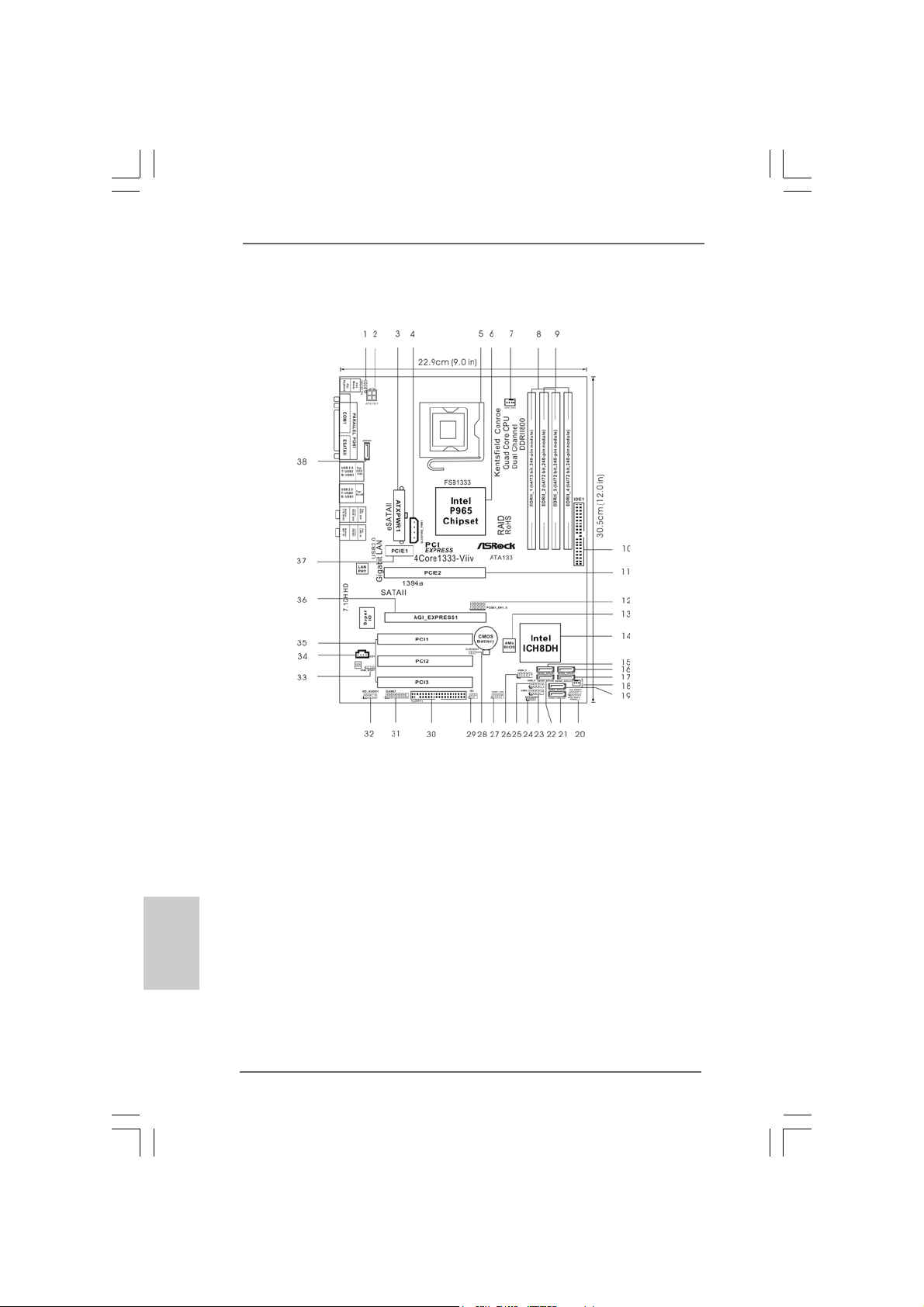
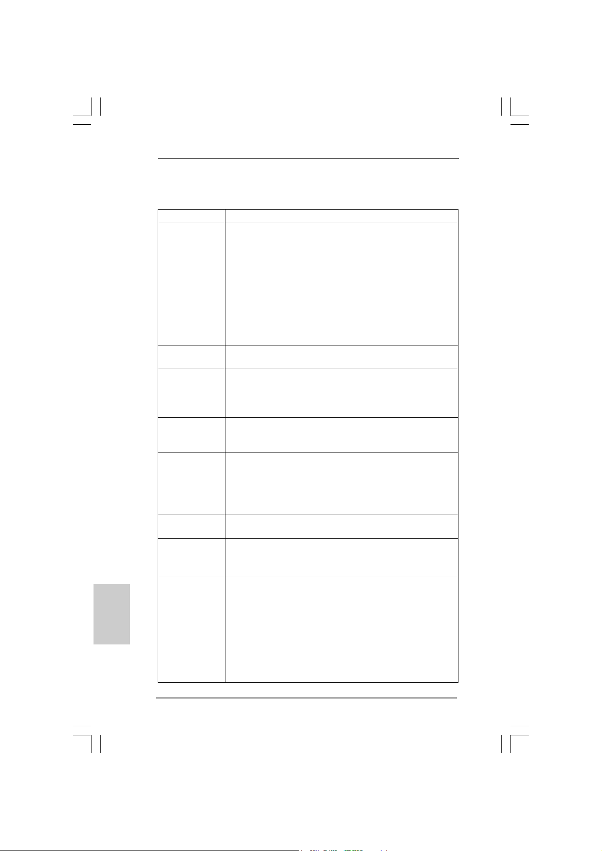
1 PS2_USB_PWR1 Jumper 20 System Panel Hea der (P ANEL1)
2 A TX 12V Connector (A TX12V1) 21 SA T AII Connector (SA TAII_4 (PORT3))
3 A TX Power Connector (ATXPWR1) 22 SA TAII Connector (SATAII_6 (PORT5))
4 SLI / XFIRE Power Connector 23 USB 2.0 Header (USB6_7, Blue)
5 775-Pin CPU Socket 24 Chassis Speaker Header (SPEAKER 1)
6 North Bridge Controller 25 USB 2.0 Header (USB8_9, Blue)
7 CPU Fan Connector (CPU_FAN1) 26 USB 2.0 Header (USB4_5, Blue)
8 2 x 240-pin DDRII DIMM Slots 27 Front Panel IEEE 1394 Header (FRONT_1394)
(Dual Channel A: DDRII_1, DDRII_3; Yellow) 28 Clear CMOS Jumper (CLRCMOS1)
9 2 x 240-pin DDRII DIMM Slots 29 DeskExpress Hot Plug Detection Header
(Dual Channel B: DDRII_2, DDRII_4; Orange) (IR1)
10 IDE1 Connector (IDE1, Blue) 30 Floppy Connector (FLOPPY1)
11 PCI Express x16 Slot (PCIE2) 31 Game Port Header (GAME1)
12 PCIEX1_EN1 - 5 32 Front Panel Audio Header (HD_AUDIO1)
13 Flash Memory 33 HDMI_SPDIF Header (HDMI_SPDIF1)
14 South Bridge Controller 34 Internal Audio Connector: CD1 (Black)
15 SA T AII Connector (SA TAII_5 (PORT4)) 35 PCI Slots (PCI1 - 3)
16 SA T AII Connector (SA T AII_1 (PORT0)) 36 AGI Express Slot (PCI Express x4)
17 SA TAII Connector (SA T AII_2 (PORT1)) 37 PCI Express x1 Slot (PCIE1)
18 Chassis Fan Connector (CHA_FAN1) 38 eSATAII Connector (eSA T AII)
19 SA T AII Connector (SA TAII_3 (PORT2))
ASRock 4Core1333-Viiv Motherboard
Page 3
ASRASR
ock 1394_eSock 1394_eS
ASR
ock 1394_eS
ASRASR
ock 1394_eSock 1394_eS
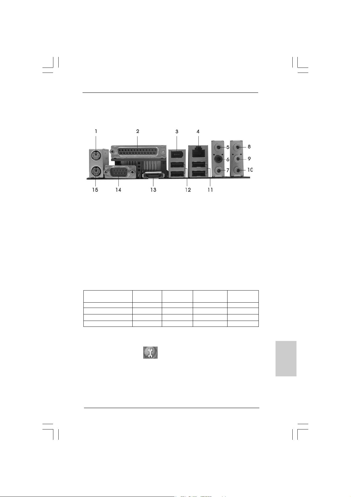
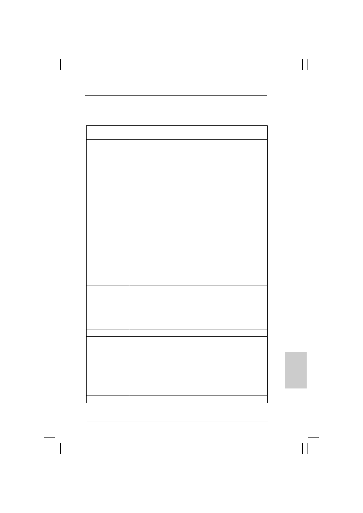
1 PS/2 Mouse Port (Green) * 9 Front Speaker (Lime)
2 Parallel Port 1 0 Microphone (Pink)
3 IEEE 1394 Port 11 USB 2.0 Ports (USB23)
4 RJ-45 Port 12 USB 2.0 Ports (USB01)
5 Side Speaker (Gray) 13 eSATAII Port
6 Rear Speaker (Black) 14 COM Port
7 Central / Bass (Orange) 15 PS/2 Keyboard Port (Purple)
8 Line In (Light Blue)
* If you use 2-channel spea ker, please connect the speaker’s plug into “Front Speaker Jack”. See
the table below for connection details in accordance with the type of speaker you use.
AA
TT
AII I/O PlusAII I/O Plus
A
T
AII I/O Plus
AA
TT
AII I/O PlusAII I/O Plus
TABLE for Audio Output Connection
Audio Output Channels Front Speaker Rear Speaker Central / Bass Side Speaker
(No. 9) (No. 6) (No. 7) (No. 5)
2 V -- -- -4VV---6 VVV-8 VVVV
* To enable Multi-Streaming function, you need to connect a front panel audio cable to the front
panel audio header. After restarting your computer, you will find “Mixer” tool on your system.
Please select “Mixer ToolBox” , click “Enable playback multi-streaming”, and click
“ok”. Choose “2CH”, “4CH”, “6CH”, or “8CH” and then you are allowed to select “Realtek HDA
Primary output” to use Rear Speaker, Central/Bass, and Front Speaker, or select “Realtek HDA
Audio 2nd output” to use front panel audio.
ASRock 4Core1333-Viiv Motherboard
EnglishEnglish
EnglishEnglish
English
33
3
33
Page 4
ASRock DeskExpress SpecificationsASRock DeskExpress Specifications
ASRock DeskExpress Specifications
ASRock DeskExpress SpecificationsASRock DeskExpress Specifications
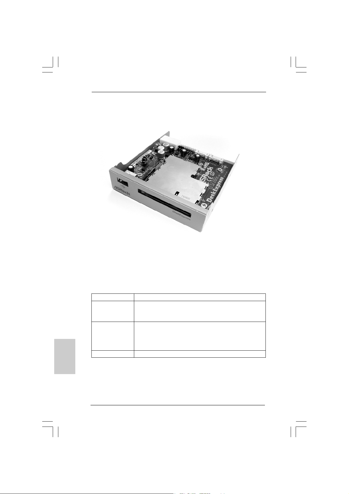
ASRock DeskExpre ss, providing one front USB 2.0 port and one Express card slot to
support all kinds of Express cards, such as eSATAII card, USB 2.0 card, LAN card
and flash disc, offers you a device to expand the availability conveniently in addition
to the PCI Express interface on this motherboard. Please refer to below table for
ASRock DeskExpress specifications. For installation procedures of ASRock
DeskExpress, please refer to page 18 for details.
English
EnglishEnglish
EnglishEnglish
44
4
44
Interface - Express card / USB 2.0
Slot - 1 x 54 mm Express card slot
(compatible with ExpressCard/54 and ExpressCard/34)
- 1 x USB 2.0 port
Connector - 1 x Hot Plug Detection header (JHP1; black)
- 1 x USB 2.0 header (USB1; blue)
- 1 x 4 pin power connector (PWR1; white)
- 2 x PCIE ports (PCIE1; yellow / PCIE2; white)
Case Dimension - 115 mm x 99 mm x 25 mm, fit in 3.5-in bay
ASRock 4Core1333-Viiv Motherboard
Page 5
1. Introduction1. Introduction
1. Introduction
1. Introduction1. Introduction
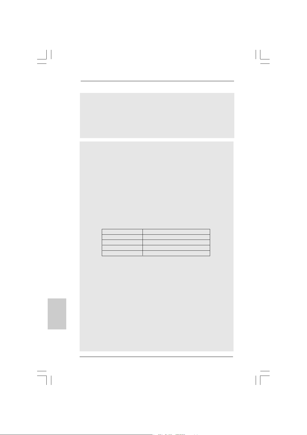
Thank you for purchasing ASRock 4Core1333-Viiv motherboard, a reliable
motherboard produced under ASRock’s consistently stringent quality control. It delivers excellent performance with robust design conforming to ASRock’s commitment to quality and endurance.
This Quick Installation Guide contains introduction of the motherboard and step-bystep installation guide. More detailed information of the motherboard can be found in
the user manual presented in the Support CD.
Because the motherboard specifications and the BIOS software might be
updated, the content of this manual will be subject to change without
notice. In case any modifications of this manual occur, the updated
version will be available on ASRock website without further notice. You
may find the latest VGA cards and CPU support lists on ASRock website
as well. ASRock website
1.1 Package Contents1.1 Package Contents
1.1 Package Contents
1.1 Package Contents1.1 Package Contents
ASRock 4Core1333-Viiv Motherboard
(ATX Form Factor: 12.0-in x 9.0-in, 30.5 cm x 22.9 cm)
ASRock 4Core1333-Viiv Quick Installation Guide
ASRock 4Core1333-Viiv Support CD
Motherboard Accessories
One 80-conductor Ultra ATA 66/100/133 IDE Ribbon Cable
One Ribbon Cable for a 3.5-in Floppy Drive
Two Serial ATA (SATA) Data Cables (Optional)
One Serial ATA (SATA) HDD Power Cable (Optional)
One HDMI_SPDIF Cable (Optional)
One “ASRock 1394_eSATAII I/O Plus” I/O Panel Shield
http://www.asrock.com
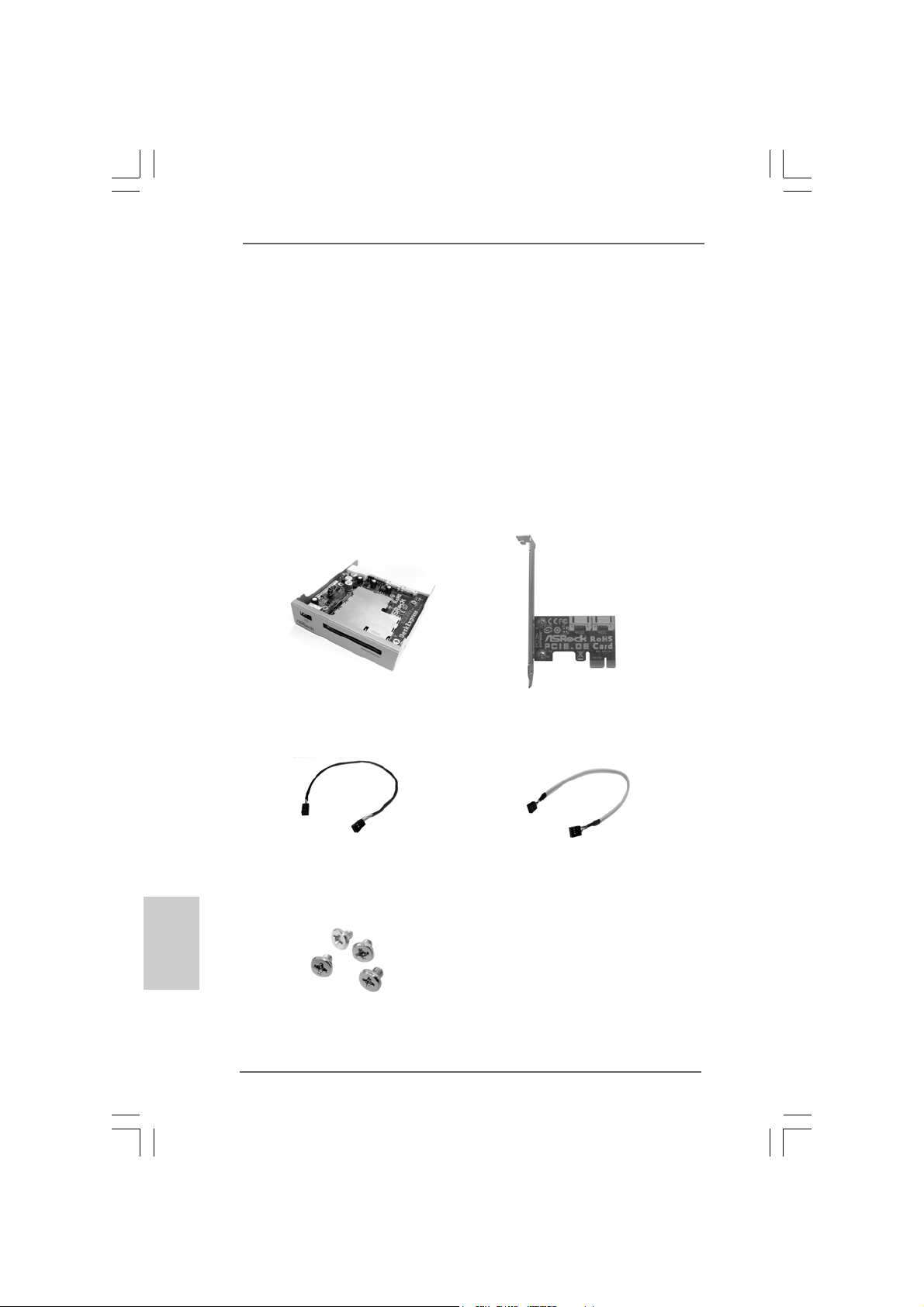
ASRock DeskExpress Accessories (Optional)
One ASRock DeskExpress
One ASRock PCIE_DE Card
Two Serial A TA (SATA) Data Cables
One DeskExpress Hot Plug Detection Cable
One USB Header Data Cable
Four Screws
ASRock 4Core1333-Viiv Motherboard
EnglishEnglish
EnglishEnglish
English
55
5
55
Page 6
English
EnglishEnglish
EnglishEnglish
1.21.2
SpecificationsSpecifications
1.2
Specifications
1.21.2
SpecificationsSpecifications
Platform - ATX Form Factor: 12.0-in x 9.0-in, 30.5 cm x 22.9 cm
CPU - LGA 775 for Intel® CoreTM 2 Quad / CoreTM 2 Extreme /
CoreTM 2 Duo / Pentium® XE / Pentium® D / Pentium® Dual Core /
Pentium® 4 / Celeron® / Celeron® D, supporting Quad Core
Kentsfield processors
- Compatible with all FSB1333/1066/800/533MHz CPUs
(see CAUTION 1)
- Intel® ViivTM Ready (see CAUTION 2)
- Supports Hyper-Threading Technology (see CAUTION 3)
- Supports Untied Overclocking Technology (see CAUTION 4)
- Supports EM64T CPU
Chipset - Northbridge: Intel® P965
- Southbridge: Intel® ICH8DH
Memory - Dual Channel DDRII Memory Technology (see CAUTION 5)
- 4 x DDRII DIMM slots
- Support DDRII800/667/533 (see CAUTION 6)
- Max. capacity: 8GB (see CAUTION 7)
Hybrid Booster - CPU Frequency Stepless Control (see CAUTION 8)
- ASRock U-COP (see CAUTION 9)
- Boot Failure Guard (B.F.G.)
Expansion Slot - Supports ATI
- 1 x PCI Express x16 slot
- 1 x AGI Express slot (PCI Express x4)
- 1 x PCI Express x1 slot
- 3 x PCI slots
Audio - 7.1 CH Windows® VistaTM Premium Level HD Audio
(ALC888 Audio Codec)
LAN - Gigabit LAN 10/100/1000 Mb/s
- Giga PHY Intel® 82566DC
- Supports Wake-On-LAN
Rear Panel I/O ASRock 1394_eSATAII I/O Plus
- 1 x PS/2 Mouse Port
- 1 x PS/2 Keyboard Port
- 1 x Serial Port: COM1
- 1 x Parallel Port (ECP/EPP Support)
- 4 x Ready-to-Use USB 2.0 Ports
- 1 x eSATAII Port
- 1 x RJ-45 Port
- 1 x IEEE 1394 Port
TM
CrossFire
TM
66
6
66
ASRock 4Core1333-Viiv Motherboard
Page 7
- HD Audio Jack: Side Speaker/Rear Speaker/Central/Bass/
Line in/Front Speaker/Microphone (see CAUTION 10)
Connector - 6 x SATAII 3.0Gb/s connectors, support RAID (RAID 0,
RAID 1, RAID 10, RAID 5 and Intel Matrix Storage), NCQ,
AHCI and “Hot Plug” functions (see CAUTION 11)
- 1 x eSATAII 3.0Gb/s connector (shared with 1 SATAII
connector), support NCQ, AHCI and “Hot Plug” function
(see CAUTION 12)
- 1 x ATA133 IDE connector (supports 2 x IDE devices)
- 1 x Floppy connector
- 1 x DeskExpress Hot Plug Detection header
- 1 x Game header
- 1 x HDMI_SPDIF header
- 1 x IEEE 1394 header
- CPU/Chassis FAN connector
- 20 pin ATX power connector
- 4 pin 12V power connector
- SLI/XFIRE power connector
- CD in header
- Front panel audio connector
- 3 x USB 2.0 headers (support 6 USB 2.0 ports)
(see CAUTION 13)
BIOS Feature - 4Mb AMI BIOS
- AMI Legal BIOS
- Supports “Plug and Play”
- ACPI 1.1 Compli ance Wake Up Events
- Supports jumperfree
- AMBIOS 2.3.1 Support
Support CD - Drivers, Utilities, AntiVirus Software (Trial Version)
Hardware - CPU Temperature Sensing
Monitor - Chassis Temperature Sensing
- CPU Fan Ta chometer
- Chassis Fan Tachometer
- CPU Quiet Fan
- Voltage Monitoring: +12V, +5V, +3.3V, CPU Vcore
OS - Microsoft® Windows® 2000 / XP / XP Media Center / XP 64-bit
Certifications - FCC, CE, WHQL
/ Vista
TM
/ VistaTM 64-bit compliant (see CAUTION 14)
EnglishEnglish
EnglishEnglish
English
ASRock 4Core1333-Viiv Motherboard
77
7
77
Page 8
English
EnglishEnglish
EnglishEnglish
WARNING
Please realize that there is a certain risk involved with overclocking, including adjusting
the setting in the BIOS, applying Untied Overclocking Technology, or using the thirdparty overclocking tools. Overclocking may affect your system stability, or even
cause damage to the components and devices of your system. It should be done at
your own risk and expense. We are not responsible for possible damage caused by
overclocking.
CAUTION!
1. FSB1333-CPU will operate in overclocking mode.
2. Intel® ViivTM technology is only supported under 32-bit OS of Windows® XP
Media Center and Windows® VistaTM Home Premium and Ultimate Edition.
For the minimum hardware requirements of Intel® ViivTM technology, ple ase
refer to page 10 for details.
3. About the setting of “Hyper Threading Technology”, please check page 55
of “User Manual” in the support CD.
4. This motherboard supports Untied Overclocking Technology. Please read
“Untied Overclocking Technology” on page 45 for details.
5. This motherboard supports Dual Cha nnel Me mory Technology . Bef ore you
implement Dual Channel Memory Technology, make sure to read the
installation guide of memory modules on page 14 for proper installation.
6. Please check the table below for the CPU FSB frequency and its
corresponding memory support frequency.
CPU FSB Frequency Memory Support Frequency
1333 DDRII667
1066 DDRII533, DDRII667, DDRII800
800 DDRII533, DDRII667, DDRII800
533 DDRII533
7. Due to the operating system limitation, the actual memory size may be
less than 4GB for the reservation for system usage under Windows
and Windows® VistaTM. For Windows® XP 64-bit and Windows® VistaTM 64bit with 64-bit CPU, there is no such limitation.
8. Although this motherboard offers stepless control, it is not recommended
to perform over-clocking. Frequencies other than the recommended CPU
bus frequencies may cause the instability of the system or damage the
CPU.
9. While CPU overheat is detected, the system will automatically shutdown.
Before you resume the system, please check if the CPU fan on the
motherboard functions properly and unplug the power cord, then plug it
back again. To improve heat dissipation, remember to spray thermal
grease between the CPU a nd the he atsink when you install the PC syste m.
10. For microphone input, this motherboard supports both stereo and mono
modes. For audio output, this motherboard supports 2-channel, 4-channel,
6-channel, and 8-channel modes. Please check the table on page 3 for
proper connection.
®
XP
88
8
88
ASRock 4Core1333-Viiv Motherboard
Page 9
11. Before installing SATAII hard disk to SATAII connector, please read the
“SATAII Hard Disk Setup Guide” on page 37 to a djust your SATAII hard disk
drive to SATAII mode. You can also connect SATA hard disk to SATAII
connector directly.
12. This motherboard supports eSATAII interface, the external SATAII
specification. Please read “eSATAII Interface Introduction” on page 34 for
details about eSATAII and eSATAII installation procedures.
13. Power Management for USB 2.0 works fine under Microsoft® Windows
VistaTM 64-bit / VistaTM / XP 64-bit / XP SP1 or SP2 / 2000 SP4.
14. Microsoft® Windows® VistaTM / VistaTM 64-bit driver keeps on updating now. As
long as we have the latest driver, we will update it to our website in the future.
Please visit our website for Microsoft® Windows® VistaTM / VistaTM 64-bit driver
and related information.
ASRock website http://www.asrock.com
1.31.3
Minimum Hardware RMinimum Hardware R
1.3
Minimum Hardware R
1.31.3
Minimum Hardware RMinimum Hardware R
TMTM
TM
TMTM
VistaVista
Vista
VistaVista
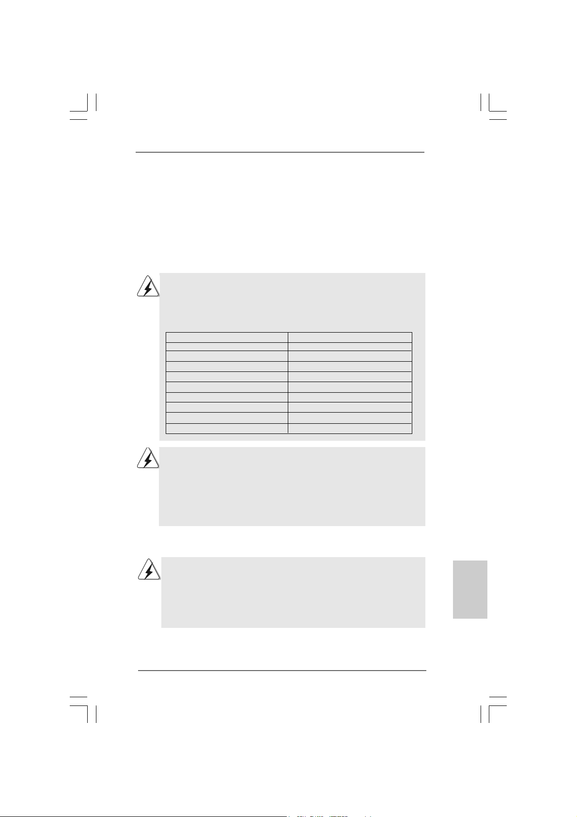
For system integrators and users who purchase this motherboard and
plan to submit Windows® VistaTM Premium 2007 and Basic logo, please
follow below table for minimum hardware requirements.
CPU Celeron D 326
Memory 1GB system memory (Premium)
VGA DX9.0 with WDDM Driver
Premium 2007 and Basic Logo Premium 2007 and Basic Logo
Premium 2007 and Basic Logo
Premium 2007 and Basic Logo Premium 2007 and Basic Logo
512MB Single Channel (Ba sic)
with 128bit VGA memory (Premium)
with 64bit VGA memory (Basic)
equirement Tequirement T
equirement T
equirement Tequirement T
able for Wable for W
able for W
able for Wable for W
®
indowsindows
indows
indowsindows
®®
®
®®
* After June 1, 2007, all Windows® VistaTM systems are required to meet above
minimum hardware requirements in order to qualify for Windows® VistaTM Premium
2007 logo.
ASRock 4Core1333-Viiv Motherboard
EnglishEnglish
EnglishEnglish
English
99
9
99
Page 10
1.41.4
Minimum Hardware RMinimum Hardware R
1.4
Minimum Hardware R
1.41.4
Minimum Hardware RMinimum Hardware R
®®
TM TM
®
TM
®®
IntelIntel
Intel
IntelIntel
If you want to use Intel® ViivTM technology on this motherboard, please
follow below table for minimum hardware requirements.
CPU Intel® Dual Core CPU *
HDD SATAII HDD with NCQ function
Suggested OS Windows® XP 32-bit Media Center or Windows® VistaTM 32-bit
* Currently, Intel® ViivTM technology requires Intel® Dual Core CPU or above except
Intel® Pentium® Dual Core E2XXX CPU. For further information of CPU support list,
please refer to Intel® website for updates.
TM TM
Viiv Viiv
Viiv
Viiv Viiv
TT
echnologyechnology
T
echnology
TT
echnologyechnology
Home Premium and Ultimate Edition
equirement Tequirement T
equirement T
equirement Tequirement T
able forable for
able for
able forable for
English
EnglishEnglish
EnglishEnglish
1010
10
1010
ASRock 4Core1333-Viiv Motherboard
Page 11

2.2.
InstallationInstallation
2.
Installation
2.2.
InstallationInstallation
Pre-installation PrecautionsPre-installation Precautions
Pre-installation Precautions
Pre-installation PrecautionsPre-installation Precautions
Take note of the following precautions before you install motherboard components or change any motherboard settings.
1. Unplug the power cord from the wall socket before touching any
component. Failure to do so may cause severe damage to the
motherboard, peripherals, and/or components.
2. To avoid damaging the motherboard components due to static
electricity, NEVER place your motherboard directly on the carpet
or the like. Also remember to use a grounded wrist strap or touch
a safety grounded object before you handle components.
3. Hold components by the edges and do not touch the ICs.
4. Whenever you uninstall any component, place it on a grounded
antstatic pad or in the bag that comes with the component.
5. When placing screws into the screw holes to secure the
motherboard to the chassis, please do not over-tighten the
screws! Doing so may damage the motherboard.
2.12.1
CPU InstallationCPU Installation
2.1
CPU Installation
2.12.1
CPU InstallationCPU Installation
For the installation of Intel 775-LAND CPU,
please follow the steps below.
775-Pin Socket Overview
Before you insert the 775-LAND CPU into the socket, please check if
the CPU surface is unclean or if there is any bent pin on the socket.
Do not force to insert the CPU into the socket if above situation is
found. Otherwise, the CPU will be seriously damaged.
ASRock 4Core1333-Viiv Motherboard
1111
11
1111
EnglishEnglish
EnglishEnglish
English
Page 12
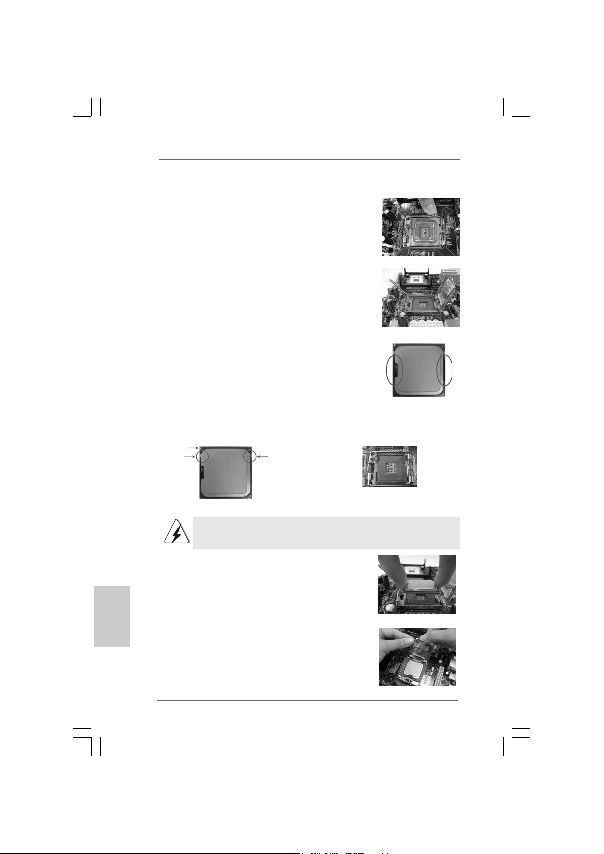
Step 1. Open the socket:
Step 1-1. Disengaging the lever by depressing
down and out on the hook to clear
retention tab.
Step 1-2. Rotate the load lever to fully open po-
sition at approximately 135 degrees.
Step 1-3. Rotate the load plate to fully open po-
sition at approximately 100 degrees.
Step 2. Insert the 775-LAND CPU:
Step 2-1. Hold the CPU by the edges where are
marked with black lines.
Step 2-2. Orient the CPU with IHS (Integrated
Heat Sink) up. Locate Pin1 and the two
orientation key notches.
Pin1
orientation
key notch
orientation
key notch
Pin1
alignment key
black line
black line
alignment key
English
EnglishEnglish
EnglishEnglish
1212
12
1212
775-Pin Socket
775-LAND CPU
For proper inserting, please ensure to match the two orientation key
notches of the CPU with the two alignment keys of the socket.
Step 2-3. Carefully pla ce the CPU into the socket
by using a purely vertical motion.
Step 2-4. Verify that the CPU is within the socket
and properly mated to the orient keys.
Step 3. Remove PnP Ca p (Pick a nd Place Cap):
Use your left hand index finger and thumb to
support the load plate edge, engage PnP cap
with right hand thumb and peel the cap from the
socket while pressing on center of PnP cap to
assist in removal.
ASRock 4Core1333-Viiv Motherboard
Page 13
1. It is recommended to use the cap tab to handle and avoid kicking
off the PnP cap.
2. This cap must be placed if returning the motherboard for after
service.
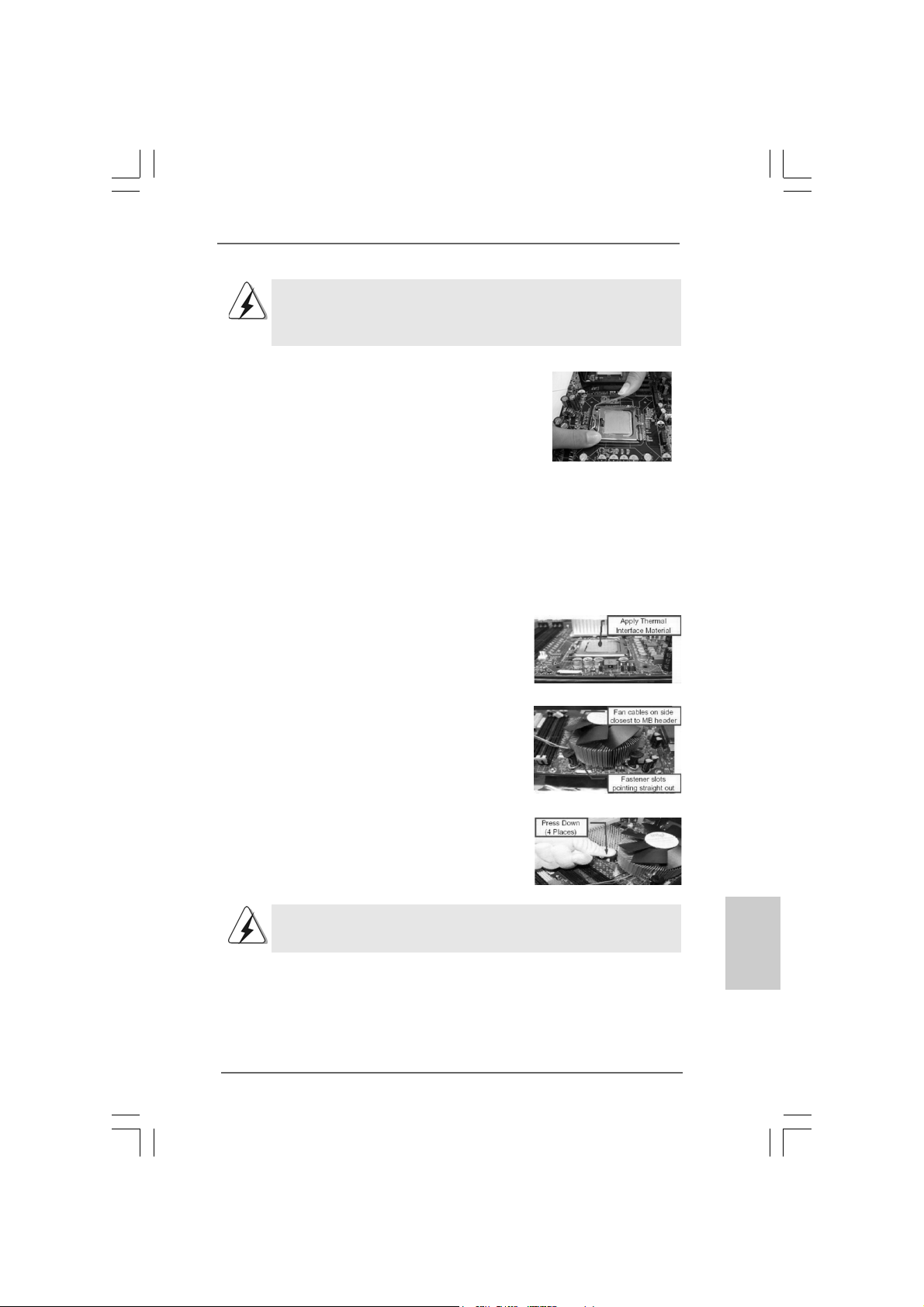
Step 4. Close the socket:
Step 4-1. Rotate the load plate onto the IHS.
Step 4-2. While pressing down lightly on load
plate, engage the load lever.
Step 4-3. Secure load lever with load plate tab
under retention tab of load lever.
2.22.2
Installation of CPU Fan and HeatsinkInstallation of CPU Fan and Heatsink
2.2
Installation of CPU Fan and Heatsink
2.22.2
Installation of CPU Fan and HeatsinkInstallation of CPU Fan and Heatsink
For proper installation, please kindly refer to the instruction manuals of your CPU fan
and heatsink.
Below is an example to illustrate the installation of the heatsink for 775-LAND CPU.
Step 1. Apply thermal interface material onto center
of IHS on the socket surface.
Step 2. Place the heatsink onto the socket. Ensure
fan cables are oriented on side closest to the
CPU fan connector on the motherboard
(CPU_FAN1, see page 2, No. 7).
Step 3. Align fasteners with the motherboard
throughholes.
Step 4. Rotate the fastener clockwise, then press
down on fastener caps with thumb to install
and lock. Repeat with remaining fasteners.
If you press down the fasteners without rotating them clockwise,
the heatsink cannot be secured on the motherboard.
Step 5. Connect fan header with the CPU fan
connector on the motherboard.
Step 6. Secure excess cable with tie-wrap to ensure
cable does not interfere with fan operation or
contact other components.
ASRock 4Core1333-Viiv Motherboard
1313
13
1313
EnglishEnglish
EnglishEnglish
English
Page 14
2.3 Installation of Memory Modules (DIMM)2.3 Installation of Memory Modules (DIMM)
2.3 Installation of Memory Modules (DIMM)
2.3 Installation of Memory Modules (DIMM)2.3 Installation of Memory Modules (DIMM)
4Core1333-Viiv motherboard provides four 240-pin DDRII (Double Data Rate II)
DIMM slots, and supports Dual Channel Memory Technology. For dual channel
configuration, you always need to install identical (the same brand, speed,
size and chip-type) DDRII DIMM pair in the slots of the same color. In other words,
you have to install identical DDRII DIMM pair in Dual Channel A (DDRII_1 and
DDRII_3; Yellow slots; see p.2 No.8) or identical DD RII DIMM pair in Dual Chan-
nel B (DDRII_2 and DDRII_4; Orange slots; see p.2 No.9), so that Dual Channel
Memory Technology can be activated. This motherboard also allows you to
install four DDRII DIMMs for dual channel configuration, and please install iden-
tical DDRII DIMMs in all four slots. You may refer to the Dual Channel Memory
Configuration Table below.
Dual Channel Memory Configurations
DDRII_1 DDRII_2 DDRII_3 DDRII_4
(Yellow Slot) (Orange Slot) (Yellow Slot) (Orange Slot)
(1) Populated - Populated (2) - Populated - Populated
(3)* Populated Populated Populated Populated
* For the configuration (3), please install identical DDRII DIMMs in all four slots.
English
EnglishEnglish
EnglishEnglish
1414
14
1414
1. If you want to install two memory modules, for optimal compatibility
and reliability, it is recommended to install them in the slots of the
same color. In other words, install them either in the set of yellow
slots (DDRII_1 and DDRII_3), or in the set of orange slots (DDRII_2
and DDRII_4).
2. If only one memory module or three memory modules are installed
in the DDRII DIMM slots on this motherboard, it is unable to activate
the Dual Channel Memory Technology .
3. If a pair of memory modules is NOT installed in the same Dual
Channel, for exa mple, in stalling a pair of memory module s in D DRII_1
and DDRII_2, it is unable to activate the Dual Channel Memory
Technology .
4. It is not allowed to install a DDR memory module into DDRII slot;
otherwise, this motherboard and DIMM may be damaged.
5. If you plan to use ATITM PCI Express VGA card on this motherboard,
the total system memory size should be above 512MB.
ASRock 4Core1333-Viiv Motherboard
Page 15
Installing a DIMMInstalling a DIMM
Installing a DIMM
Installing a DIMMInstalling a DIMM
Please make sure to disconnect power supply before adding or
removing DIMMs or the system components.
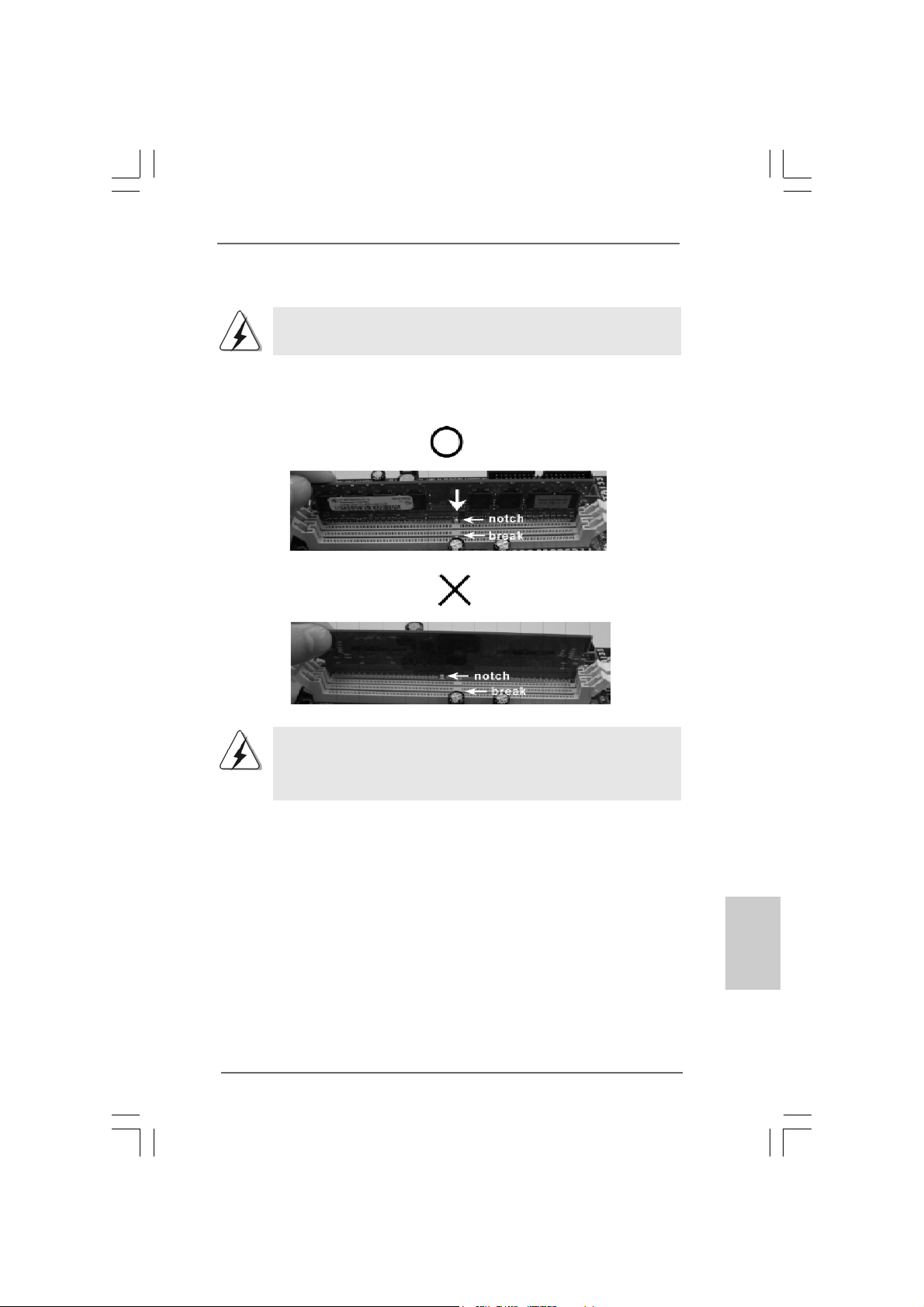
Step 1. Unlock a DIMM slot by pressing the retaining clips outward.
Step 2. Align a DIMM on the slot such that the notch on the DIMM matches the break
on the slot.
The DIMM only fits in one correct orientation. It will cause permanent
damage to the motherboard and the DIMM if you force the DIMM into the
slot at incorrect orientation.
Step 3. Firmly insert the DIMM into the slot until the retaining clips at both ends fully
snap back in place and the DIMM is properly seated.
ASRock 4Core1333-Viiv Motherboard
1515
15
1515
EnglishEnglish
EnglishEnglish
English
Page 16
2.4 Expansion Slots (PCI, PCI Express, and AGI Express2.4 Expansion Slots (PCI, PCI Express, and AGI Express
2.4 Expansion Slots (PCI, PCI Express, and AGI Express
2.4 Expansion Slots (PCI, PCI Express, and AGI Express2.4 Expansion Slots (PCI, PCI Express, and AGI Express
Slots) Slots)
Slots)
Slots) Slots)
There are 3 PCI slots, 2 PCI Express slots, and 1 AGI Express slot (PCI Express x4)
on this motherboard.
PCI slots: PCI slots are used to install expansion cards that have the 32-bit PCI
interface.
PCIE slots: PCIE1 (PCIE x1 slot) is used for PCI Express cards with x1 lane width
cards, such as Gigabit LAN card, SATA2 card and ASRock PCIE_DE
card (optional).
PCIE2 (PCIE x16 slot) is used for PCI Express cards with x16 lane
width graphics cards.
AGI Express slot (PCI Express x4):
AGI Express slot (PCI Express x4) is used to install PCI Express
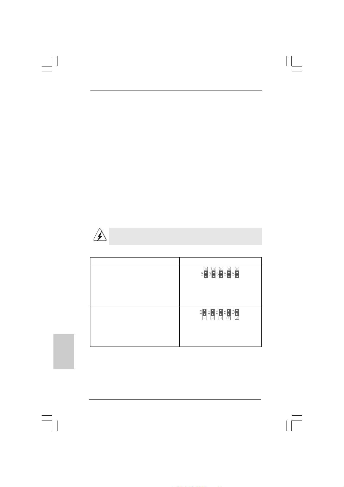
expansion cards. You need to adjust the jumpers in advance to enable
AGI Express slot (PCI Express x4), but under this situation, onboard IDE
connector (IDE1) will be disabled. Please refer to below table for proper
jumper settings.
If you plan to install only one PCI Express card on this motherboard, please
install it on PCIE2 (PCIE x16 slot).
Function Jumper Settings
English
EnglishEnglish
EnglishEnglish
1616
16
1616
Enable AGI Expre ss slot (PCIE x4)
/ Disable onboard IDE conne ctor (IDE1)
Enable onboard IDE connector (IDE1)
/ Disable AGI Express slot (PCIE x4)
(Default)
ASRock 4Core1333-Viiv Motherboard
PCIE x 1_EN2
PCIE x 1_EN1
PCIE x 1_EN2
PCIE x 1_EN1
PCIE x 1_EN3
PCIE x 1_EN4
PCIE x 1_EN5
PCIE x 1_EN3
PCIE x 1_EN4
PCIE x 1_EN5
Page 17
Installing an expansion cardInstalling an expansion card
Installing an expansion card
Installing an expansion cardInstalling an expansion card
Step 1. Before installing the expansion card, please make sure that the power
supply is switched off or the power cord is unplugged. Please read the
documentation of the expansion card and make necessary hardware
settings for the card before you start the installation.
Step 2. Remove the bracket facing the slot that you intend to use. Keep the screws
for later use.
Step 3. Align the card connector with the slot and press firmly until the card is
completely seated on the slot.
Step 4. Fasten the card to the chassis with screws.
ASRock 4Core1333-Viiv Motherboard
1717
17
1717
EnglishEnglish
EnglishEnglish
English
Page 18
2.5 ASRock DeskExpress Installation Guide2.5 ASRock DeskExpress Installation Guide
2.5 ASRock DeskExpress Installation Guide
2.5 ASRock DeskExpress Installation Guide2.5 ASRock DeskExpress Installation Guide
This motherboard supports ASRock DeskExpress, providing PCI Express slot for one
front USB 2.0 port and all kinds of PCI Express interfa ce cards, such as eSA TAII card,
USB 2.0 card, LAN card and flash disc. ASRock DeskExpress provides a device for
you to expand the availability conveniently in a ddition to the PCI Expre ss interface on
this motherboard. To use ASRock DeskExpress function, please check below
accessories (optional) from the motherboard gift box pack in advance.
A. ASRock DeskExpress
B. ASRock PCIE_DE card
C. DeskExpre ss Hot Plug Detection Cable
D. USB Header Data Ca ble
E. Screws
A. ASRock DeskExpress B. ASRock PCIE_DE Card
English
EnglishEnglish
EnglishEnglish
1818
18
1818
C. DeskExpress Hot Plug
Detection Cable
E. Screws
ASRock 4Core1333-Viiv Motherboard
D. USB Header Data Cable
Page 19
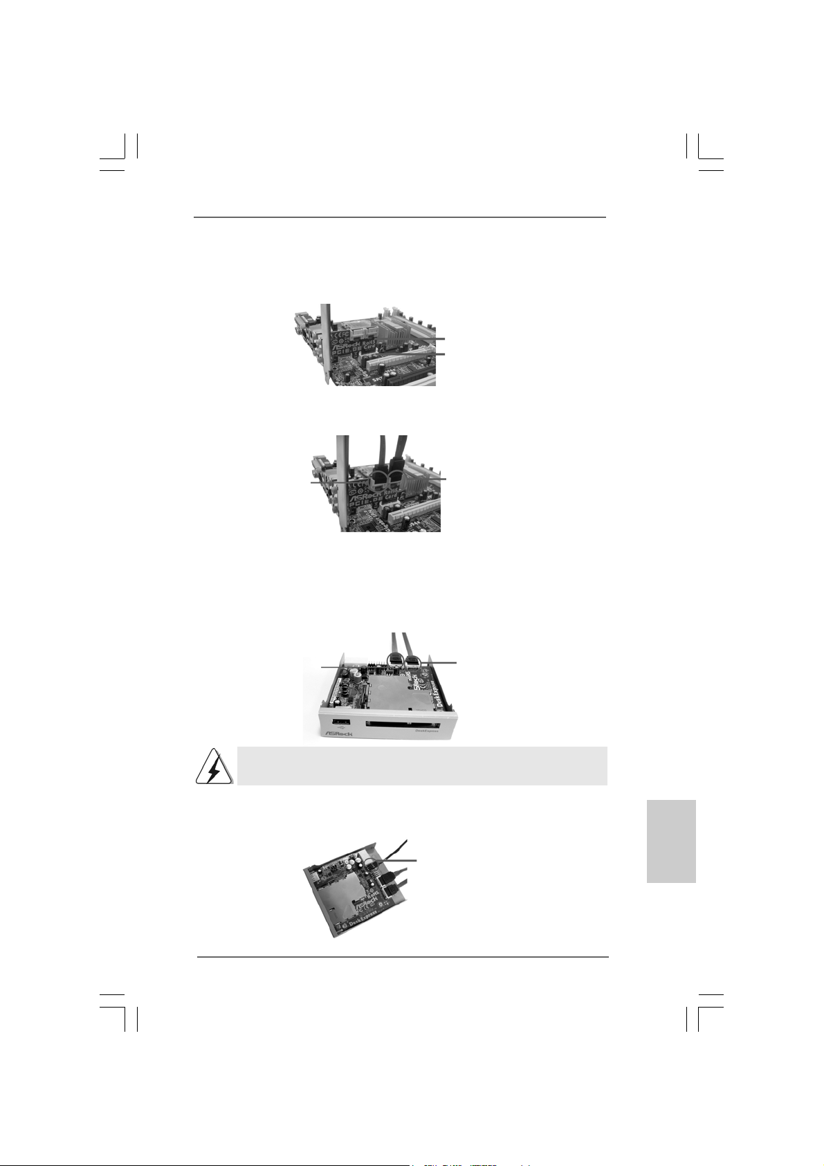
Step 1. Install ASRock PCIE_DE card to PCIE1 slot on this motherboard. For the
proper installation of ASRock PCIE_DE card, please refer to the installation
guide on page 16.
ASRock PCIE_DE card
PCIE1 slot
Step 2. Connect either end of SATA data cable to PCIE1 (yellow) / PCIE2 (white)
port on ASRock PCIE_DE card.
PCIE2 port
(white)
Step 3. Connect the other end of SATA data cable to PCIE1 (yellow) / PCIE2 (white)
port on ASRock DeskExpress. Please correctly connect the SATA data
cables to the ports with corresponding colors on ASRock PCIE_DE card
and ASRock DeskExpress. (PCIE1 (yellow) port to PCIE1 (yellow) port;
PCIE2 (white) port to PCIE2 (white) port.)
E
PCIE2 port
(white)
If you do not connect SATA data cable to the correct port, ASRock
PCIE_DE card and ASRock DeskExpress will not function.
Step 4. Connect either end of DeskExpress Hot Plug detection cable to Hot Plug
detection header (JHP1; black) on ASRock DeskExpress.
PCIE1 port
(yellow)
PCIE1 port
(yellow)
Hot Plug detection header
(JHP1; black)
EnglishEnglish
EnglishEnglish
English
ASRock 4Core1333-Viiv Motherboard
1919
19
1919
Page 20
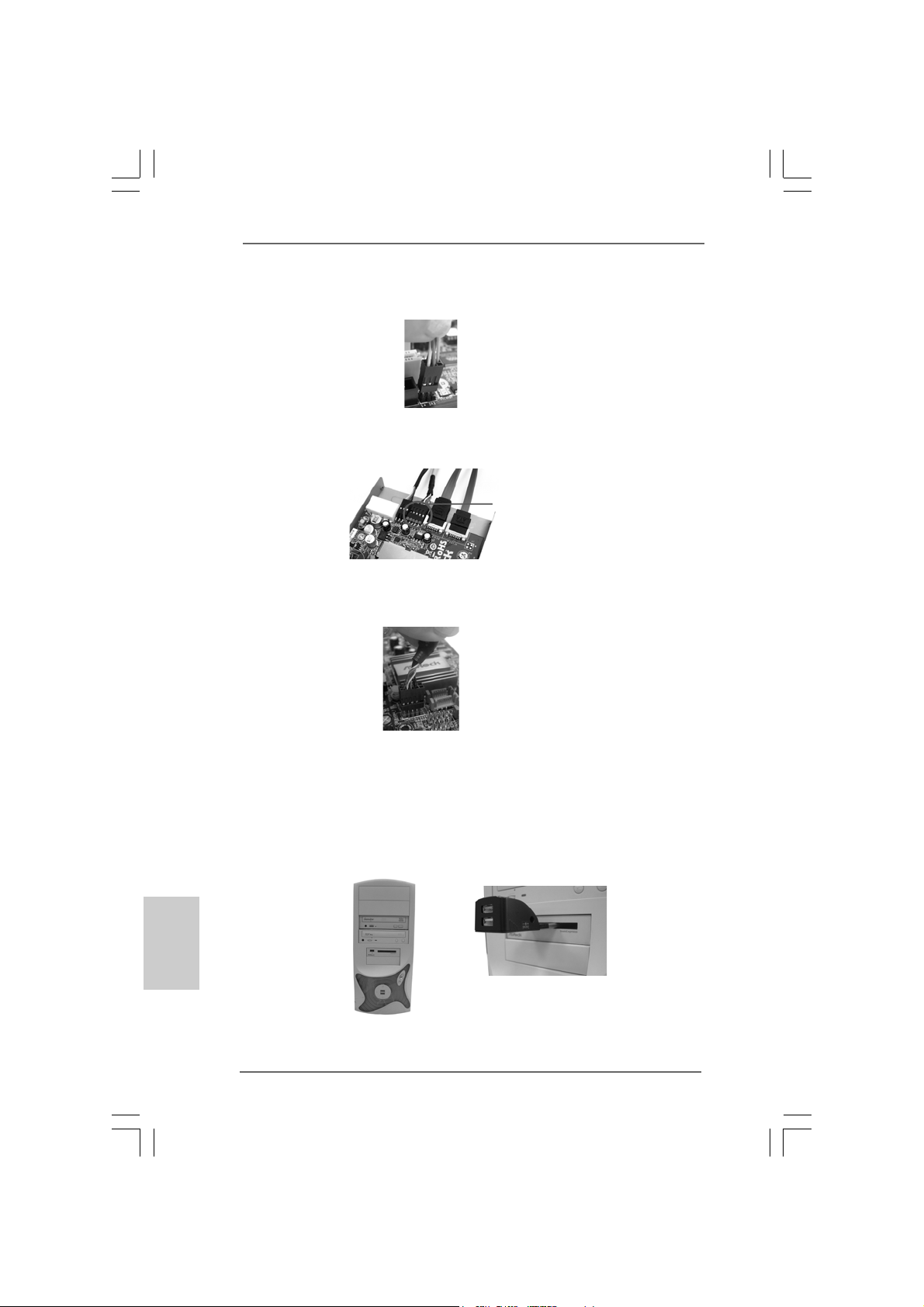
Step 5. Connect the other end of DeskExpress Hot Plug detection cable to
DeskExpress Hot Plug detection header (IR1; see p.2 No.29) on this
motherboard.
DeskExpress Hot Plug
detection header (IR1)
Step 6. Connect either end of USB header data cable to USB 2.0 header
(USB1; blue) on ASRock DeskExpress.
USB 2.0 header (USB1; blue)
Step 7. Connect the other end of USB header data cable to any USB 2.0 header
(USB4_5, USB6_7 or USB8_9; see p.2 No.26, 23 or 25) on this motherboard.
USB 2.0 header (blue)
English
EnglishEnglish
EnglishEnglish
2020
20
2020
Step 8. Fasten ASRock DeskExpress to 3.5-in bay on the chassis with screws.
Step 9. Boot your system.
Step 10. The function of ASRock DeskExpress is enabled. You can insert your USB
flash drive or any PCI Express interface card to ASRock DeskExpress.
(USB flash drive and PCI Express interface card are not bundled with this
motherboard. Please refer to the product vendor for related information.)
ASRock 4Core1333-Viiv Motherboard
Page 21
TMTM
TM
2.6 CrossFire2.6 CrossFire
2.6 CrossFire
2.6 CrossFire2.6 CrossFire
TMTM
Operation Guide Operation Guide
Operation Guide
Operation Guide Operation Guide
This motherboard supports CrossFireTM feature. CrossFireTM technology offers the
most advantageous mea n s available of combining multi ple high perf ormance Gra phics
Processing Units (GPU) in a single PC. Combining a range of different operating
modes with intelligent software design and an innovative interconnect mechanism,
CrossFireTM enables the highest possible level of performance and image quality in
any 3D application. Currently CrossFireTM feature is supported with Windows® XP
with Service Pack 2. Please check ATITM website for driver updates.
What graphics cards work with CrossFireTM?
A complete CrossFireTM system requires a CrossFireTM Ready motherboard, a
CrossFireTM Edition graphics card and a compatible standard Radeon (CrossFire
Ready) graphics card from the same series, or two CrossFireTM Ready cards if they
are software enabled. This applies to cards from ATITM or any of its partners.
Cards For AGI Express Slot Cards For PCIE2 Slot
Radeon X1950Pro Series Radeon X1950Pro Series
Radeon X1950XTX Series Radeon X1950XTX CrossFire
Radeon X1950 Series Radeon X1950 CrossFireTM Edition
Radeon X1900 Series Radeon X1900 CrossFireTM Edition
Radeon X1800 Series Radeon X1800 CrossFireTM Edition
Radeon X1650Pro Series Radeon X1650Pro Series
Radeon X1600 Series Radeon X1600 Series
Radeon X1300 Series Radeon X1300 Series
Radeon X850 Series Radeon X850 CrossFireTM Edition
1. If a customer incorrectly configures their system they will not see the
performance benefits of CrossFireTM. All three CrossFireTM components, a
CrossFireTM Ready graphics card, a CrossFireTM Ready motherboard and a
CrossFireTM Edition co-processor graphics card, must be installed correctly to
benefit from the CrossFireTM multi-GPU platform.
2. If you pair a 12-pipe CrossFireTM Edition card with a 16-pipe card, both cards will
operate as 12-pipe cards while in CrossFireTM mode.
TM
Edition
TM
TMTM
TM
Enjoy the benefit of CrossFireEnjoy the benefit of CrossFire
Enjoy the benefit of CrossFire
Enjoy the benefit of CrossFireEnjoy the benefit of CrossFire
Currently, A TITM has released Radeon X850XT , X1800XT, X1900XT, X1950XT , X1950Pro,
X1950XTX, X1300, X1650 and X1600 CrossFireTM cards, which require different
methods to enable CrossFire
X850XT as the example graphics card. For other CrossFireTM cards that ATITM has
released or will release in the future, please refer to ATITM graphics card manuals for
detailed installation guide.
TM
TMTM
feature. In the below procedures, we use Radeon
ASRock 4Core1333-Viiv Motherboard
2121
21
2121
EnglishEnglish
EnglishEnglish
English
Page 22
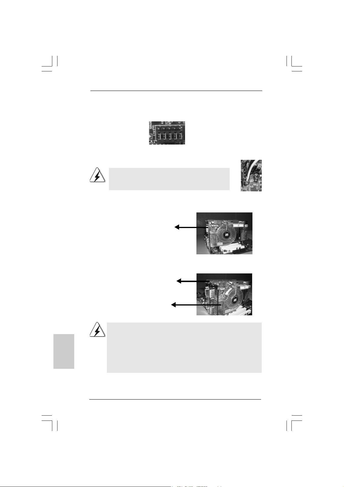
Step 1. Adjust the jumpers on this motherboard to enable AGI Express slot
(PCI Express x4). Please refer to the pictures below for proper jumper
setting.
PCIEX1_EN1-5: Short Pin1, Pin2
Step 2. Connect to the system power supply. Please connect a hard disk power
connector to SLI/XFIRE Power connector on this motherboard.
It is recommended to use 500-Watt power supply or greater
to perform the benefit of CrossFireTM feature for Radeon
X850XT, X1900 and X1950 series.
Step 3. Install the standard Radeon (CrossFireTM Ready) graphics card to AGI
Express slot (PCI Express x4). For the proper installation procedures,
please refer to section “Expansion Slots”.
Standard Radeon
(CrossFireTM Ready)
graphics card
Step 4. Install the Radeon CrossFireTM Edition graphics card to PCIE2 slot. For the
proper installation procedures, please refer to section “Expansion Slots”.
English
EnglishEnglish
EnglishEnglish
2222
22
2222
Radeon CrossFire
Edition graphics card
Standard Radeon
(CrossFireTM Ready)
graphics card
1. You are allowed to install two CrossFireTM Edition graphics cards to both slots, or you
may use one CrossFire
(CrossFireTM Ready) graphics card from the same series.
2. For A TITM Radeon X1300, X1600, X1650 and X1950Pro series, there are no CrossFire
Edition graphics cards. You can still install two regular graphics cards from the same
series on PCIE2 slot and AGI Express slot (PCI Express x4) to support CrossFireTM.
Besides, please connect the monitor cable to the graphics card on PCIE2 slot.
TM
TM
Edition graphics cards a nd a compatible standard Radeon
ASRock 4Core1333-Viiv Motherboard
TM
Page 23
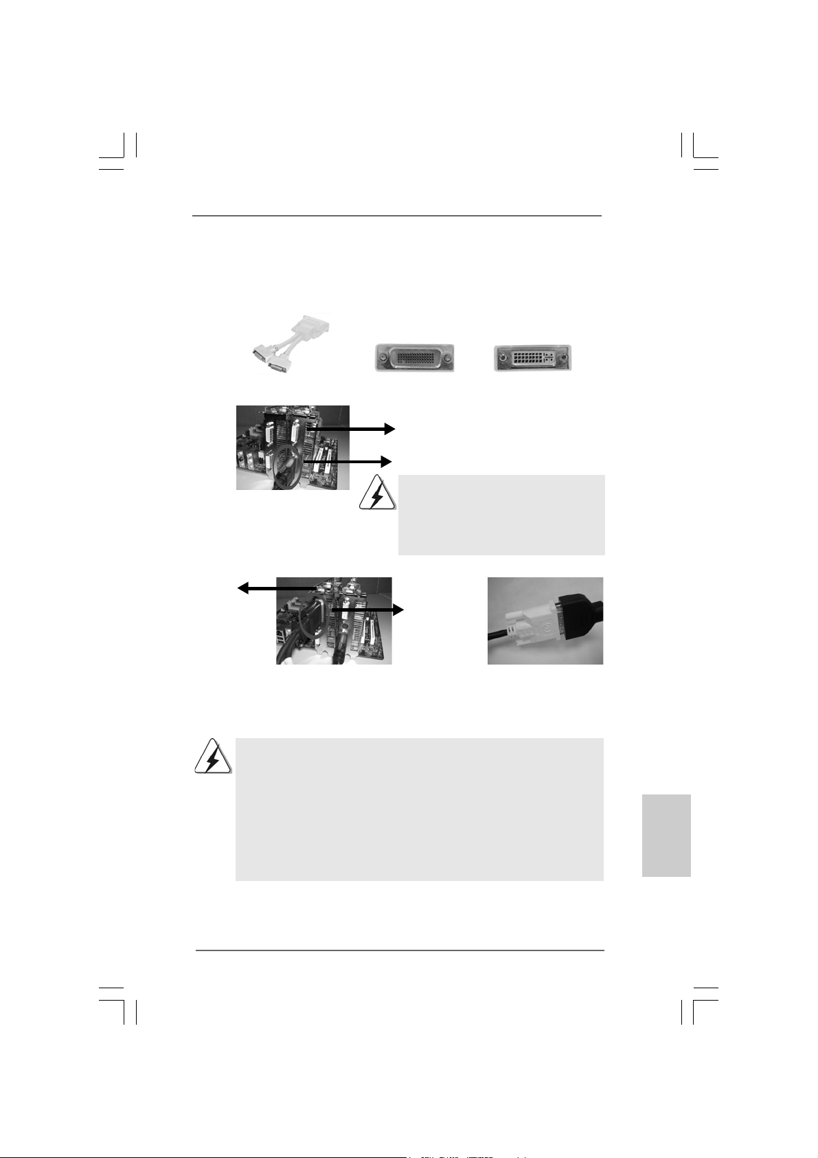
Step 5. Correctly connect the DVI-DMS cable to the monitor connector and two
graphics cards that you install. (If you install two standard Radeon
(CrossFireTM Ready) graphics cards to this motherboard, please skip this
step.)
DVI-DMS cable DMS connector
Connect the DVI-DMS
cable to DVI connector of
the compatible standard
Radeon (CrossFire
Ready) graphics card.
Radeon
TM
CrossFire
Edition graphics
card
DVI connector
Standard Radeon (CrossFireTM Ready)
graphics card
D VI connector
There are two DVI connectors on the
standard Radeon (CrossFireTM Ready)
graphics card. Please connect the DVI-DMS
TM
cable to the correct DVI connector; otherwise
, the graphics card will not work.
DMS
connector
Connect the DVI-DMS
cable to DMS connector
of the CrossFire
graphics card.
If you install two CrossFireTM Edition graphics cards to this motherboard, please
connect one end of DVI-DMS cable to the monitor, another end to DMS of one
of the CrossFireTM Edition graphics cards to PCIE2 slot, and the other end to
DVI of another CrossFireTM Edition graphics card to AGI Express slot (PCI
Express x4). If you install one CrossFireTM Edition graphics card and one
compatible standard Radeon (CrossFireTM Ready) graphics card to this
motherboard, please connect one end of DVI-DMS cable to the monitor,
another end to DMS of the CrossFireTM Edition graphics card, and the other end
to DVI of the compatible standard Radeon (CrossFireTM Ready) graphics card.
TM
Edition
Connect the DVI-DMS
cable to the monitor
connector.
EnglishEnglish
EnglishEnglish
English
ASRock 4Core1333-Viiv Motherboard
2323
23
2323
Page 24
Step 6. Power on your computer and boot into OS.
Step 7. Remove the A TITM driver if you have any VGA driver installed in your system.
The Catalyst Uninstaller is an optional download. We recommend using this
utility to uninstall any previously installed Catalyst drivers prior to installation.
Please visit this website for the driver:
http://support.ati.com/ics/support/DLRedirect.asp?
fileIDExt=050553d40196ef109fff37cbb40aaf28&accountID=737&deptID=894
Step 8. Install the required drivers to your system. Please visit the websites below
for installing the drivers that ATITM recommends:
A. ATITM recommends Windows® XP Service Pack 2 or higher to be
installed (If you have Windows® XP Service Pack 2 or higher installed
in your system, there is no need to download it again):
http://www.microsoft.com/windowsxp/sp2/default.mspx
B. You must have Microsoft .NET Framework installed prior to
downloading and installing the CATALYST Control Center:
http://www.microsoft.com/downloads/details.aspx?
FamilyId=262D25E3-F589-4842-8157-034D1E7CF3A3&displaylang=en
Step 9. Restart your computer.
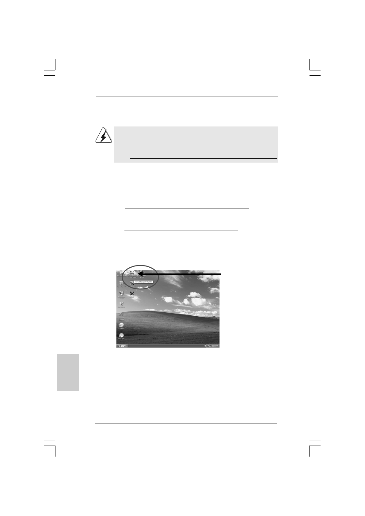
Step 10. Install the VGA card drivers to your system, and restart your computer.
Then you will find “ATI Catalyst Control Center” on your desktop.
You will find “ATI Catalyst
Control Center” on your
desktop.
English
EnglishEnglish
EnglishEnglish
2424
24
2424
ASRock 4Core1333-Viiv Motherboard
Page 25
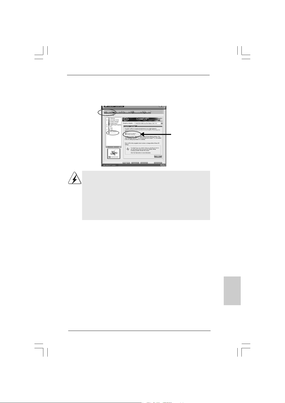
Step 11. Double-click “ATI Catalyst Control Center”. Click “View”, and select “Ad-
vanced View”. Click “CrossFire
TM
”, and then set the option “Enable
CrossFireTM” to “Yes”.
View
CrossFire
TM
If you install one Radeon CrossFireTM Edition graphics card a nd one compatible
standard Radeon (CrossFireTM Ready) graphics card to this motherboard but
not two Radeon CrossFireTM Edition graphics cards, please as well follow the
above steps. However, although you have selected the option “Enable
CrossFireTM”, the CrossFireTM function can not work actually. Your computer
will automatically reboot. After restarting your computer, please confirm whether
the option “Enable CrossFireTM” in “ATI Catalyst Control Center” is selected or
not; if not, please select it again, and then you are able to enjoy the benefit of
CrossFire
TM
feature.
Enable CrossFire
Step 12. You can freely enjoy the benefit of CrossFireTM feature.
* CrossFireTM appearing here is a registered trademark of ATITM Technologies Inc., and is used
only for identification or explanation and to the owners’ benefit, without intent to infringe.
2.7 Surround Display Feature2.7 Surround Display Feature
2.7 Surround Display Feature
2.7 Surround Display Feature2.7 Surround Display Feature
This motherboard supports Surround Display upgrade. With the external add-on
PCI Express VGA card, you can easily enjoy the benefits of Surround Display
feature. For the detailed instruction, please refer to the document at the following
path in the Support CD:
..\ Surround Display Information
TM
EnglishEnglish
EnglishEnglish
English
ASRock 4Core1333-Viiv Motherboard
2525
25
2525
Page 26
2.8 Jumpers Setup2.8 Jumpers Setup
2.8 Jumpers Setup
2.8 Jumpers Setup2.8 Jumpers Setup
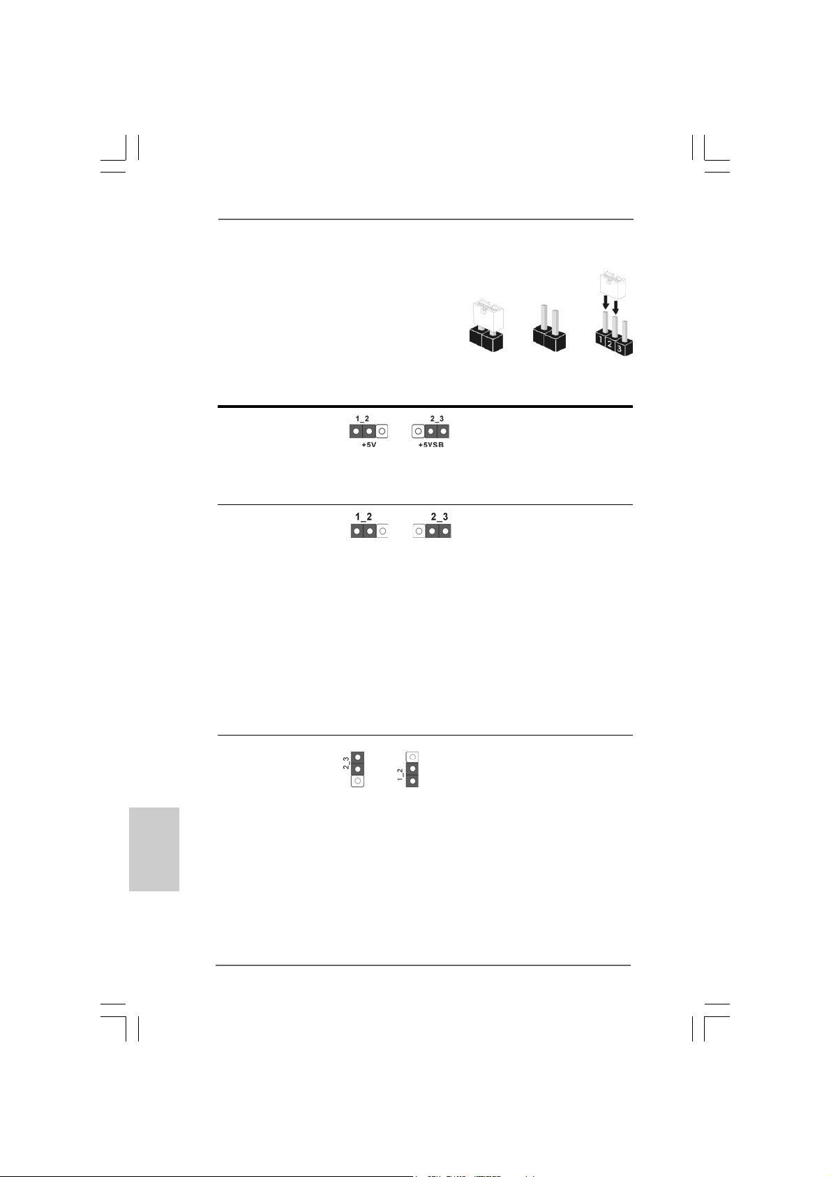
The illustration shows how jumpers are
setup. When the jumper cap is placed on
pins, the jumper is “Short”. If no jumper cap
is placed on pins, the jumper is “Open”. The
illustration shows a 3-pin jumper whose pin1
and pin2 are “Short” when jumper cap is
placed on these 2 pins.
Jumper Setting Description
PS2_USB_PWR1 Short pin2, pin3 to enable
(see p.2 No. 1) +5VSB (standby) for PS/2
or USB wake up events.
Note: To select +5VSB, it requires 2 Amp and higher standby current provided by
power supply.
Clear CMOS Jumper
(CLRCMOS1)
(see p.2, No. 28)
Note: CLRCMOS1 allows you to clear the data in CMOS. The data in CMOS includes
system setup information such as system password, date, time, and system
setup parameters. To clear and reset the system parameters to default setup,
please turn off the computer and unplug the power cord from the power
supply. After waiting for 15 seconds, use a jumper cap to short pin2 and pin3
on CLRCMOS1 for 5 seconds. However, please do not clear the CMOS right
after you update the BIOS. If you need to clear the CMOS when you just finish
updating the BIOS, you must boot up the system first, and then shut it down
before you do the clear-CMOS action.
Clear CMOSDefault
OpenShort
English
EnglishEnglish
EnglishEnglish
2626
26
2626
PCIEX1_EN1-5 Short pin2, pin3 to enable onboard
(see p.2 No. 12) IDE connector (IDE1) and disable
AGI Express slot (PCI Express x4).
Default
ASRock 4Core1333-Viiv Motherboard
Short pin1, pin2 to enable AGI
Express slot (PCI Express x4) and
disable onboard IDE connector
(IDE1).
Page 27
2.9 Onboard Headers and Connectors2.9 Onboard Headers and Connectors
2.9 Onboard Headers and Connectors
2.9 Onboard Headers and Connectors2.9 Onboard Headers and Connectors
Onboard headers and connectors are NOT jumpers. Do NOT place
jumper caps over these headers and connectors. Placing jumper caps
over the headers and connectors will cause permanent damage of the
motherboard!
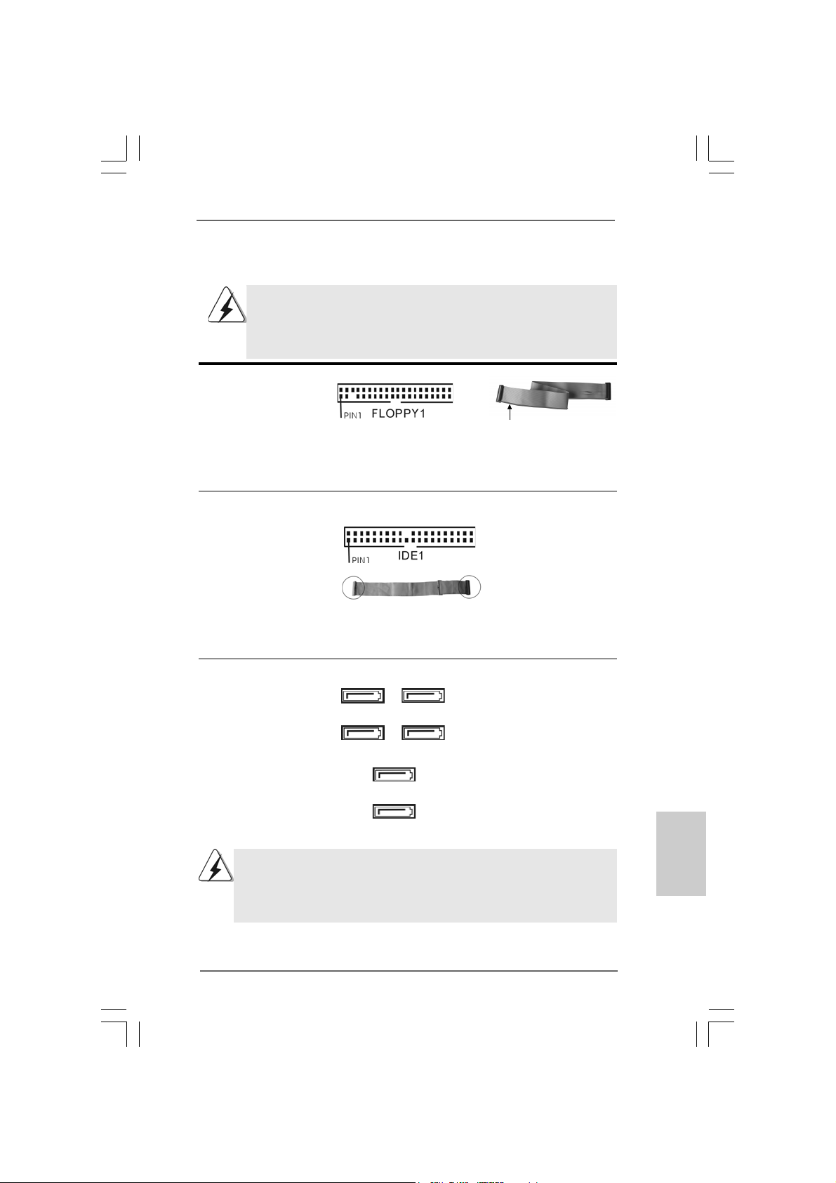
FDD connector
(33-pin FLOPPY1)
(see p.2 No. 30)
the red-striped side to Pin1
Note: Make sure the red-striped side of the cable is plugged into Pin1 side of the
connector.
Primary IDE connector (Blue)
(39-pin IDE1, see p.2 No. 10)
connect the blue end
to the motherboard
connect the black end
to the IDE devices
80-conductor ATA 66/100/133 cable
Note: Please refer to th e i n struction of your IDE device vendor for the details.
Serial ATAII Connectors These six Serial ATAII (SATAII)
(SAT AII_1 (Port0): see p.2, No. 16) connectors support SATA data
(SAT AII_2 (Port1): see p.2, No. 17) cables for internal storage
(SAT AII_3 (Port2): see p.2, No. 19) devices. The current SATAII
(SAT AII_4 (Port3): see p.2, No. 21) interface allows up to 3.0 Gb/s
(SAT AII_5 (Port4): see p.2, No. 15) data transfer rate.
(SAT AII_6 (Port5): see p.2, No. 22)
SATAII_6 (Port5) connector can be used for internal storage device or
be connected to eSATAII connector to support eSATAII device. Please
read “eSA T AII Interfa ce Introduction” on page 34 for details a bout eSA T AII
and eSATAII installation procedures.
SAT AII_5 (Port4)
SAT AII_6 (Port5)
SAT AII_1 (Port0)
SAT AII_2 (Port1)
SAT AII_3 (Port2)
SAT AII_4 (Port3)
ASRock 4Core1333-Viiv Motherboard
2727
27
2727
EnglishEnglish
EnglishEnglish
English
Page 28
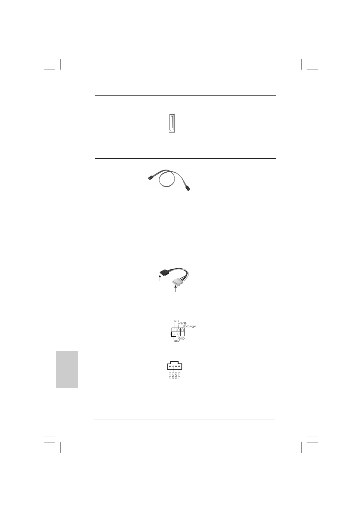
eSATAII Connector This eSATAII connector
(eSAT AII: see p.2, No. 38) supports SATA data cable for
external SATAII function. The
eSATAII
current eSATAII interface
allows up to 3.0 Gb/s data
transfer rate.
Serial A TA (SA TA) Either end of the SATA data cable
Data Cable can be connected to the SATA /
(Optional) SATAII hard disk or the SATAII
connector on this motherboard.
You can also use the SATA data
cable to connect SATAII_6
(Port5) connector and eSATAII
connector. If you use ASRock
DeskExpress on this
motherboard, please connect
PCIE1 / PCIE2 port on ASRock
PCIE_DE card and PCIE1 / PCIE2
port on ASRock DeskExpress.
Serial ATA (SATA) Please connect the black end of
Power Cable SATA power cable to the power
(Optional) connector on each drive. Then
connect to the SAT A
HDD power connector
connect to the
power supply
connect the white end of SATA
power cable to the power
connector of the power supply.
English
EnglishEnglish
EnglishEnglish
2828
28
2828
DeskExpress Hot Plug Detection This header supports the Hot
Header Plug detection function for
(5-pin IR1) ASRock DeskExpress.
(see p.2 No. 29)
Internal Audio Connectors This connector allows you
(4-pin CD1) to receive stereo audio input
(CD1: see p.2 No. 34) from sound sources such as
CD1
a CD-ROM, D VD-ROM, TV
tuner card, or MPEG card.
ASRock 4Core1333-Viiv Motherboard
Page 29
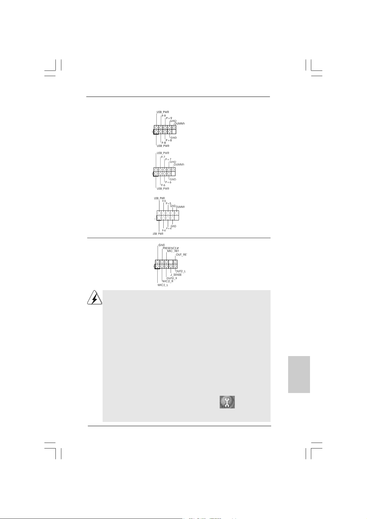
USB 2.0 Headers Besides four default USB 2.0
(9-pin USB8_9) ports on the I/O panel, there are
(see p.2 No. 25) three USB 2.0 headers on this
motherboard. Each USB 2.0
header cansupport two USB
2.0 ports.
(9-pin USB6_7)
(see p.2 No. 23)
(9-pin USB4_5)
(see p.2 No. 26)
Front Panel Audio Header This is an interface for front
(9-pin HD_AUDIO1) panel audio cable that allows
(see p.2 No. 32) convenient connection and
control of audio devices.
1. High Definition Audio supports Jack Sensing, but the panel wire on the
chassis must support HDA to function correctly. Please follow the
instruction in our manual and chassis manual to install your system.
2. If you use AC’97 audio panel, please install it to the front panel audio
header as below:
A. Connect Mic_IN (MIC) to MIC2_L.
B. Connect Audio_R (RIN) to OUT2_R and Audio_L (LIN) to OUT2_L.
C. Connect Ground (GND) to Ground (GND).
D. MIC_RET and OUT_RET are for HD audio panel only. You don’t
need to connect them for AC’97 audio panel.
E. Enter BIOS Setup Utility. Enter Advanced Settings, and then select
Chipset Configuration. Set the Front Panel Control option from
[Auto] to [Enabled].
F. Enter Windows system. Click the icon on the lower right hand
taskbar to enter Realtek HD Audio Manager.
For Windows® 2000 / XP / XP 64-bit OS:
Click “Audio I/O”, select “Connector Settings” , choose
“Disable front panel jack detection”, and save the change by
clicking “OK”.
ASRock 4Core1333-Viiv Motherboard
2929
29
2929
EnglishEnglish
EnglishEnglish
English
Page 30
For Windows® VistaTM / VistaTM 64-bit OS:
Click the right-top “Folder” icon , choose “Disable front
panel jack detection”, and save the change by clicking “OK”.
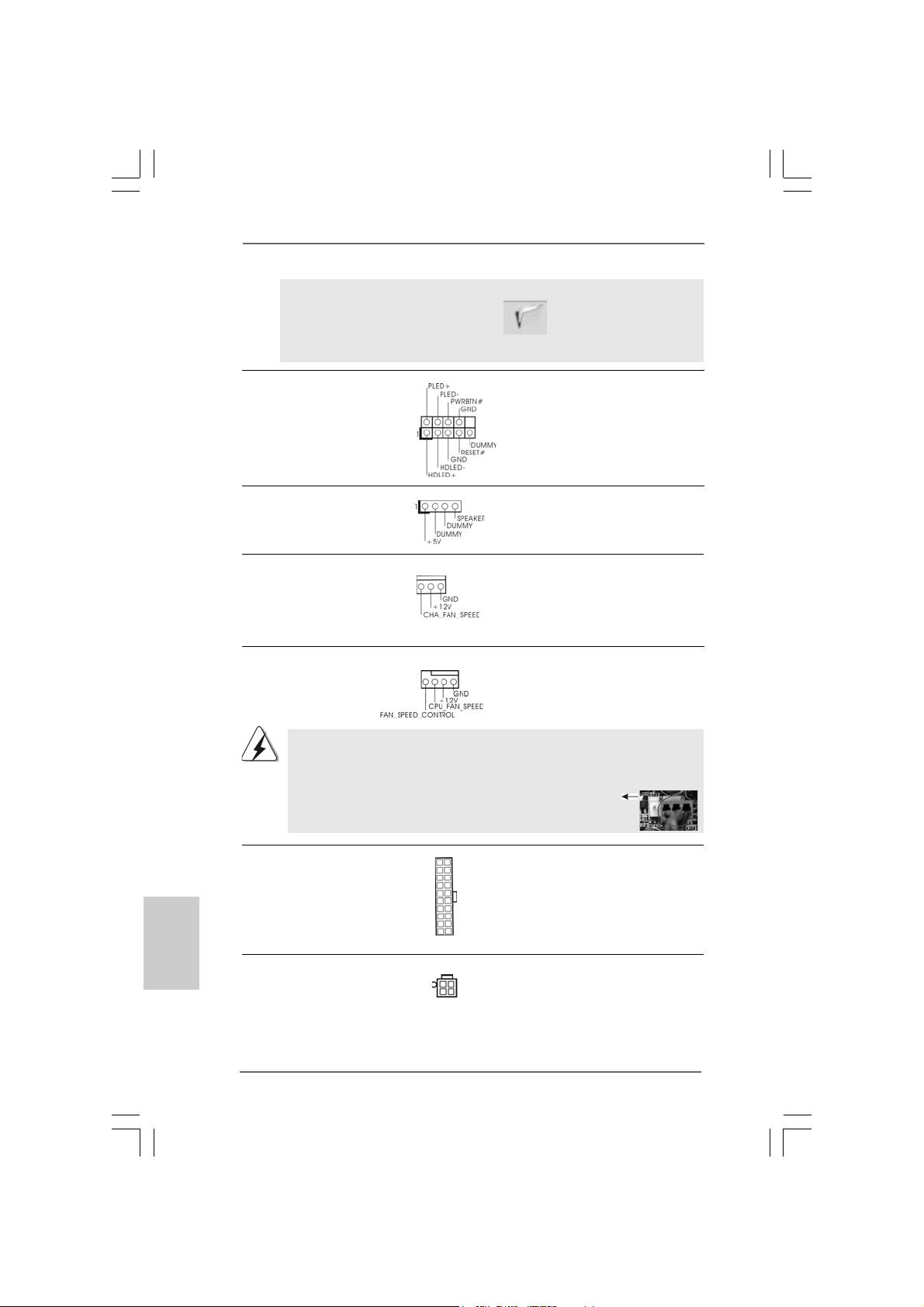
System Panel Header This header accommodates
(9-pin PANEL1) several system front panel
(see p.2 No. 20) functions.
Chassis Speaker Header Please connect the chassis
(4-pin SPEAKER 1) speaker to this header.
(see p.2 No. 24)
Chassis Fan Connector Please connect a chassis fan
(3-pin CHA_FAN1) cable to this connector and
(see p.2 No. 18) match the black wire to the
ground pin.
English
EnglishEnglish
EnglishEnglish
3030
30
3030
CPU Fan Connector Please connect a CPU fan cable
(4-pin CPU_FAN1) to this connector and match
(see p.2 No. 7) the black wire to the ground pin.
Though this motherboard provides 4-Pin CPU fan (Quiet Fan) support, the 3-Pin
CPU fan still can work successfully even without the fan speed control function.
If you plan to connect the 3-Pin CPU fan to the CPU fan connector on this
motherboard, please connect it to Pin 1-3.
4 3 2 1
Pin 1-3 Connected
3-Pin Fan Installation
ATX Power Connector Please connect an ATX power
(20-pin ATXPW R1) supply to this connector.
(see p.2 No. 3)
ATX 12V Connector Please connect an ATX 12V
(4-pin A TX12V1) power supply to this connector.
(see p.2 No. 2)
ASRock 4Core1333-Viiv Motherboard
Page 31

SLI/XFIRE Power Connector It is not necessary to use this
(4-pin SLI/XFIRE_POWER1) connector, but please connect it
(see p.2 No. 4) with a hard disk power connecor
when two graphics cards are
SLI/XFIRE_POWER1
plugged to this motherboard at
the same ti me.
Game Port Hea der Connect a Game cable to this
(15-pin GAME1) header if the Game port bracket
(see p.2 No. 31) is installed.
IEEE 1394 Header Besides one default IEEE 1394
(9-pin FRONT_1394) port on the I/O panel, there is one
(see p.2 No. 27) IEEE 1394 header
(FRONT_1394) on this
motherboard. This IEEE 1394
header cansupport one IEEE
1394 port.
HDMI_SPDIF Header HDMI_SPDIF header, providing
(3-pin HDMI_SPDIF1) SPDIF audio output to HDMI V GA
(see p.2 No. 33) card, allows the system to
connect HDMI Digital TV/
projector/LCD devices. Please
connect the HDMI_SPDIF
connector of HDMI VGA card to
this header.
ASRock 4Core1333-Viiv Motherboard
3131
31
3131
EnglishEnglish
EnglishEnglish
English
Page 32

HDMI_SPDIF Cable Please connect the black end (A)
(Optional) of HDMI_SPDIF cable to the
C
B
A
HDMI_SPDIF header on the
motherboard. Then connect the
white end (B or C) of
HDMI_SPDIF cable to the
HDMI_SPDIF connector of HDMI
VGA card.
A. black end B. white end (2-pin) C. white end (3-pin)
DeskExpress Hot Plug Detection Cable If you use ASRock DeskExpress
(Optional) on this motherboard, please
connect either end of
DeskExpress Hot Plug detection
cable to DeskExpress Hot Plug
detection header (IR1) on this
motherboard or HotPlug
detection header (JHP1; black)
on ASRock DeskExpress.
USB Header Data Cable If you use ASRock Des kExpress
(Optional) on this motherboard, please
connect either end of
USB header data cable to USB
2.0 header (USB4_5, USB6_7 or
USB8_9) on this motherboard or
USB 2.0 header (USB1; blue) on
ASRock DeskExpress.
English
EnglishEnglish
EnglishEnglish
3232
32
3232
ASRock 4Core1333-Viiv Motherboard
Page 33

2.10 HDMI_SPDIF Header Connection Guide2.10 HDMI_SPDIF Header Connection Guide
2.10 HDMI_SPDIF Header Connection Guide
2.10 HDMI_SPDIF Header Connection Guide2.10 HDMI_SPDIF Header Connection Guide
HDMI (High-Definition Multi-media Interface) is an all-digital audio/video specification,
which provides an interface between any compatible digital audio/video source,
such as a set-top box, DVD player, A/V receiver and a compatible digital audio or
video monitor, such as a digital television (DTV). A complete HDMI system requires a
HDMI VGA card and a HDMI ready motherboard with a HDMI_SPDIF header. This
motherboard is equipped with a HDMI_SPDIF header, which provides SPDIF audio
output to HDMI VGA card, allows the system to connect HDMI Digital TV/projector/
LCD devices. To use HDMI function on this motherboard, please carefully follow the
below steps.
•
Step 1. Install the HDMI VGA card to the PCI Express Graphics slot on this
motherboard. For the proper installation of HDMI VGA card, please refer
to the installation guide on page 16.
Step 2. Connect the black end (A) of HDMI_SPDIF cable to the
HDMI_SPDIF header (HDMI_SPDIF1, yellow , see page 2, No.
33) on the motherboard.
Make sure to correctly connect the HDMI_SPDIF cable to the motherboard and the
HDMI VGA card according to the same pin definition. For the pin definition of
HDMI_SPDIF header and HDMI_SPDIF cable conne ctors, ple ase refer to page 31. For
the pin definition of HDMI_SPDIF connectors on HDMI VGA card, please refer to the
user manual of HDMI VGA card vendor. Incorrect connection may cause permanent
damage to this motherboard and the HDMI VGA card.
Step 3. Connect the white end (B or C) of HDMI_SPDIF cable to the HDMI_SPDIF
connector of HDMI VGA card. (There are two white ends (2-pin and 3-pin)
on HDMI_SPDIF cable. Please choose the appropriate white end according
to the HDMI_SPDIF connector of the HDMI V GA card you install.
white end
(2-pin) (B)
Please do not connect the white end of HDMI_SPDIF cable to the wrong connector
of HDMI VGA card or other VGA card. Otherwise, the motherboard and the
VGA card may be damaged. For example, this picture shows the wrong
example of connecting HDMI_SPDIF cable to the fan connector of PCI
Express VGA card. Please refer to the VGA card user manual for
connector usage in advance.
white end
(3-pin) (C)
Step 4. Connect the HDMI output connector on HDMI VGA card to
HDMI device, such as HDTV. Please refer to the user manual
of HDTV and HDMI VGA card vendor for detailed connection
procedures.
Step 5. Install HDMI VGA card driver to your system.
ASRock 4Core1333-Viiv Motherboard
3333
33
3333
EnglishEnglish
EnglishEnglish
English
Page 34

2.11 eSA2.11 eSA
2.11 eSA
2.11 eSA2.11 eSA
What is eSATAII?
This motherboard supports eSATAII interface, the external SATAII specification.
eSATAII allows you to enjoy the SATAII function provided by the I/O of your
computer, offering the high speed data transfer rate up to 3.0Gb/s, and the
convenient mobility like USB. eSATAII is equipped with Hot Plug capability that
enables you to exchange drives easily. For example, with eSATAII interface, you
may simply plug your eSATAII hard disk to the eSATAII ports instead of opening
your chassis to exchange your SATAII hard disk. Currently, on the market, the
data transfer rate of USB 2.0 is up to 480Mb/s, and for IEEE 1394 is up to 400Mb/
s. However, eSATAII provides the data transfer rate up to 3000Mb/s, which is
much higher than USB 2.0 and IEEE 1394, and still keeps the convenience of Hot
Plug feature. Therefore, on the basis of the advantageous transfer speed and the
facilitating mobile capability, in the near future, eSATAII will replace USB 2.0 and
IEEE 1394 to be a trend for external interface.
TT
AII InterAII Inter
T
AII Inter
TT
AII InterAII Inter
NOTE:
1. If you set “Configure SATAII as” option in BIOS setup to AHCI or RAID mode, Hot
Plug function is supported with eSATAII devices. Therefore, you can insert or
remove your eSATAII devices to the eSATAII ports while the system is power-on and
in working condition.
2. If you set “Configure SATAII as” option in BIOS setup to IDE mode, Hot Plug function
is not supported with eSATAII devices. If you still want to use eSATAII function in IDE
mode, please insert or remove your eSATAII devices to the eSATAII ports only when
the system is power-off.
3. Please refer to page 40 to 45 for detailed information of RAID mode, IDE mode, and
AHCI mode.
face Introductionface Introduction
face Introduction
face Introductionface Introduction
English
EnglishEnglish
EnglishEnglish
How to install eSATAII?
3434
34
3434
SATAII connector
SATAII_6 (Port5)
ASRock 4Core1333-Viiv Motherboard
eSATAII connector
(eSATAII)
Page 35

1. In order to enable the eSATAII port of the I/O shield, you need to connect the
orange SATAII connector (SATAII_6 (Port5); see p.2 No.22) and the eSATAII
connector (eSATAII; see p.2 No.38) with a SATA data cable first.
Connect the SATA
data cable to the
orange SA T AII
connector
(SAT AII_6 (Port5))
Connect the SATA
data cable to the eSATAII
connector (eSATAII)
2. Use the eSATAII device cable to connect eSATAII device and the eSATAII port
of the I/O shield.
Connect one end of the eSATAII
device cable to eSATAII device
Connect the other end of the eSATAII
device cable to eSATAII port of the I/O
shield
ASRock 4Core1333-Viiv Motherboard
3535
35
3535
EnglishEnglish
EnglishEnglish
English
Page 36

Comparison between eSATAII and other devices
IEEE 1394 400Mb/s
USB 2.0 480Mb/s
SATA 1.5Gb/s (1500Mb/s)
eSATAII/SATAII 3.0Gb/s (3000Mb/s)
English
EnglishEnglish
EnglishEnglish
3636
36
3636
ASRock 4Core1333-Viiv Motherboard
Page 37

2.12 SA2.12 SA
2.12 SA
2.12 SA2.12 SA
Before installing SATAII hard disk to your computer, please carefully read below
SATAII hard disk setup guide. Some default setting of SATAII hard disks may not
be at SATAII mode, which operate with the best performance. In order to enable
SATAII function, please follow the below instruction with different vendors to
correctly adjust your SATAII hard disk to SATAII mode in advance; otherwise, your
SATAII hard disk may fail to run at SATAII mode.
Western Digital
If pin 5 and pin 6 are shorted, SATA 1.5Gb/s will be enabled.
On the other hand, if you want to enable SATAII 3.0Gb/s, please remove the
jumpers from pin 5 and pin 6.
SAMSUNG
If pin 3 and pin 4 are shorted, SATA 1.5Gb/s will be enabled.
On the other hand, if you want to enable SATAII 3.0Gb/s, please remove the
jumpers from pin 3 and pin 4.
TT
AII Hard Disk Setup GuideAII Hard Disk Setup Guide
T
AII Hard Disk Setup Guide
TT
AII Hard Disk Setup GuideAII Hard Disk Setup Guide
HITACHI
Please use the Feature Tool, a DOS-bootable tool, for changing various ATA
features. Please visit HITACHI’s website for details:
http://www.hitachigst.com/hdd/support/download.htm
The above examples are just for your reference. For different SATAII hard
disk products of different vendors, the jumper pin setting methods may not
be the same. Please visit the vendors’ website for the updates.
ASRock 4Core1333-Viiv Motherboard
3737
37
3737
EnglishEnglish
EnglishEnglish
English
Page 38

2.132.13
Serial ASerial A
2.13
Serial A
2.132.13
Serial ASerial A
InstallationInstallation
Installation
InstallationInstallation
This motherboard adopts Intel® ICH8DH south bridge chipset that supports Serial
ATA (SATA) / Serial ATAII (SATAII) hard disks and RAID (RAID 0, RAID 1, RAID 10,
RAID 5, and Intel Matrix Storage) functions. You may install SATA / SATAII hard
disks on this motherboard for internal storage devices. This section will guide you
to install the SATA / SATAII hard disks.
STEP 1: Install the SATA / SATAII hard disks into the drive bays of your chassis.
STEP 2: Connect the SATA power cable to the SATA / SATAII hard disk.
STEP 3: Connect one end of the SATA data cable to the motherboard’s SATAII
connector.
STEP 4: Connect the other end of the SATA data cable to the SATA / SATAII hard
disk.
TT
A (SAA (SA
TT
A (SA
A (SAA (SA
A) / Serial AA) / Serial A
T
A) / Serial A
TT
A) / Serial AA) / Serial A
T
TT
1. If you plan to use RAID 0, RAID 1, or Intel Matrix Storage function, you
need to install at least 2 SATA / SATAII hard disks. If you plan to use
RAID 5 function, you need to install at least 3 SATA / SATAII hard disks.
If you plan to use RAID 10 function, you need to install at least 4 SATA /
SATAII hard disks.
2. It is not recommended to switch the “Configure SATAII as” setting between
AHCI, RAID, and IDE mode after OS installation.
TT
AII (SAAII (SA
T
AII (SA
TT
AII (SAAII (SA
TT
AII) Hard DisksAII) Hard Disks
T
AII) Hard Disks
TT
AII) Hard DisksAII) Hard Disks
English
EnglishEnglish
EnglishEnglish
3838
38
3838
ASRock 4Core1333-Viiv Motherboard
Page 39

2.14 Hot Plug and Hot Swap F2.14 Hot Plug and Hot Swap F
2.14 Hot Plug and Hot Swap F
2.14 Hot Plug and Hot Swap F2.14 Hot Plug and Hot Swap F
HDDs and eSAHDDs and eSA
HDDs and eSA
HDDs and eSAHDDs and eSA
This motherboard supports Hot Plug and Hot Swap functions for SATA / SATAII /
eSATAII Device s in RAID mode. Intel® ICH8DH south bridge chipset provides hardware
support for Advanced Host controller Interface (AHCI), a new programming interface
for SATA host controllers developed thru a joint industry effort.
NOTE
What is Hot Plug Function?
If the SATA / SATAII HDDs are NOT set for RAID configuration, it is called
“Hot Plug” for the action to insert and remove the SATA / SATAII HDDs
while the system is still power-on and in working condition.
However, please note that it cannot perform Hot Plug if the OS has been
installed into the SATA / SATAII HDD.
What is Hot Swap Function?
If SATA / SATAII HDDs are built as RAID1 or RAID 5 then it is called “Hot
Swap” for the action to insert and remove the SATA / SATAII HDDs while
the system is still power-on and in working condition.
eSATAII is equipped with Hot Plug capability that enables you to exchange
drives easily. For example, with eSATAII interface, you may simply plug your
eSATAII devices to the eSATAII ports instead of opening your chassis to
exchange your SATAII hard disk.
TT
AII DevicesAII Devices
T
AII Devices
TT
AII DevicesAII Devices
unctions for SAunctions for SA
unctions for SA
unctions for SAunctions for SA
TT
A / SAA / SA
T
A / SA
TT
A / SAA / SA
TT
T
TT
AIIAII
AII
AIIAII
ASRock 4Core1333-Viiv Motherboard
3939
39
3939
EnglishEnglish
EnglishEnglish
English
Page 40

2.152.15
Driver Installation Guide Driver Installation Guide
2.15
Driver Installation Guide
2.152.15
Driver Installation Guide Driver Installation Guide
To install the drivers to your system, please insert the support CD to your optical
drive first. Then, the drivers compatible to your system can be auto-detected and
listed on the support CD driver page. Please follow the order from up to bottom
side to install those required drivers. Therefore, the drivers you install can work
properly.
If you install Windows® XP 64-bit OS, there may be a “!” mark on the item “USB
Root Hub” in “Device Manager” after you install “Intel Viiv Driver” from our support
CD. Please follow below steps to remove it.
1. Enter “Device Manager” and select “Universal Serial Bus controllers”.
2. Right-click “USB Root Hub”, choose “Uninstall”, and select “OK” to save the
change.
3. Click the icon “Scan for hardware changes” on the top.
As soon as we have the updated USB driver, we will update it to our website. Please
visit our website for driver update in the future.
ASRock website http://www.asrock.com
English
EnglishEnglish
EnglishEnglish
2.162.16
Installing WindowsInstalling Windows
2.16
Installing Windows
2.162.16
Installing WindowsInstalling Windows
TMTM
TM
TMTM
VistaVista
Vista
VistaVista
If you want to install Windows® 2000 / XP / XP 64-bit / VistaTM / VistaTM 64-bit OS on
your SATA / SATAII HDDs with RAID functions, please follow below procedures
according to the OS you install.
2.16.1 Installing Windows2.16.1 Installing Windows
2.16.1 Installing Windows
2.16.1 Installing Windows2.16.1 Installing Windows
RAID Functions RAID Functions
RAID Functions
RAID Functions RAID Functions
If you want to install Windows® 2000 / XP / XP 64-bit on your SATA / SAT AII HDDs with
RAID functions, please follow below steps.
STEP 1: Set up BIOS.
A. Enter BIOS SETUP UTILITY Advanced screen IDE Configuration.
B. Set “ATA/IDE Configuration” to [Enhanced], and then in the option “Configure
SATAII as”, please set the option to [RAID].
STEP 2: Make a SATA / SATAII Driver Diskette.
A. Insert the Support CD into your optical drive to boot your system.
B. During POST at the beginning of system boot-up, press <F11> key, and then a
window for boot devices selection appears. Please select CD-ROM as the boot
device.
C. When you see the message on the screen, “Do you want to generate Serial
ATA driver diskette [YN]?”, press <Y>.
D. Then you will see these messages,
64-bit With RAID Functions 64-bit With RAID Functions
64-bit With RAID Functions
64-bit With RAID Functions 64-bit With RAID Functions
®
2000 / XP / XP 64-bit / Vista 2000 / XP / XP 64-bit / Vista
2000 / XP / XP 64-bit / Vista
2000 / XP / XP 64-bit / Vista 2000 / XP / XP 64-bit / Vista
®
2000 / XP / XP 64-bit With 2000 / XP / XP 64-bit With
2000 / XP / XP 64-bit With
2000 / XP / XP 64-bit With 2000 / XP / XP 64-bit With
TM TM
TM
TM TM
//
/
//
4040
40
4040
ASRock 4Core1333-Viiv Motherboard
Page 41

Please insert a diskette into the floppy drive.
WARNING! Formatting the floppy diskette will
lose ALL data in it!
Start to format and copy files [YN]?
Please insert a floppy diskette into the floppy drive, and press <Y>.
E. The system will start to format the floppy diskette and copy SATA / SATAII
drivers into the floppy diskette.
STEP 3: Use “RAID Installation Guide” to set RAID configuration.
Before you start to configure the RAID function, you need to check theinstallation
guide in the Support CD for proper configuration. Please refer to the document in the
Support CD, “Guide to SATA Hard Disks Installation and RAID Configuration”, which is
located in the folder at the following path: .. \ RAID Installation Guide
STEP 4: Install Windows® 2000 / XP / XP 64-bit OS on your system.
After making a SATA / SATAII driver diskette and using “RAID Installation Guide” to set
RAID configuration, you can start to install Windows® 2000 / XP / XP 64-bit on your
system. At the beginning of Windows setup, press F6 to install a third-party RAID
driver. When prompted, insert the SATA / SATAII driver diskette containing the Intel
RAID driver. After reading the floppy disk, the driver will be presented. Select the
driver to install according to the mode you choose and the OS you
install. Y ou may select: “Intel(R) ICH8R/DO/DH SAT A RAID Controller (Desktop ICH8RWindows 2000)” for Windows® 2000, “Intel(R) ICH8R/DO/DH SATA RAID Controller
(Desktop ICH8R-Windows XP)” for Windows® XP or “Intel(R) ICH8R/DO/DH SATA
RAID Controller (Desktop ICH8R-Windows XP64)” for Windows® XP 64-bit.
®
After the installation of Windows
to manage RAID functions, you are allowed to use both “RAID Installation Guide” and “Intel
Matrix Storage Manager Information” for RAID configuration. Please refer to the document
in the Support CD, “Guide to SATA Hard Disks Installation and RAID Configuration”, which
is located in the folder at the following path: .. \ RAID Installation Guide and the document
in the support CD, “Guide to Intel Matrix Storage Manager”, which is located in the folder at
the following path: .. \ Intel Matrix Storage Manager Information
If you want to use “Intel Matrix Storage Manager” in Windows® environment,
please install SATA / SATAII drivers from the Support CD again so that “Intel
Matrix Storage Manager” will be installed to your system as well.
2.16.2 Setting Up a “RAID Ready” System2.16.2 Setting Up a “RAID Ready” System
2.16.2 Setting Up a “RAID Ready” System
2.16.2 Setting Up a “RAID Ready” System2.16.2 Setting Up a “RAID Ready” System
®
2000 / Windows® XP / Windows® XP-64bit OS, if you want
You can also set up a “RAID Ready” system with a single SATA / SATAII hard disk.
A “RAID Ready” system can be seamlessly upgraded to RAID 0, RAID 1 or RAID 5
at a later date by using RAID migration feature of Intel Matrix Storage. The
following steps outline how to build an Intel “RAID Ready” system.
ASRock 4Core1333-Viiv Motherboard
4141
41
4141
EnglishEnglish
EnglishEnglish
English
Page 42

1. Assemble the system and attach a single SATA / SATAII hard drive.
2. Set up system BIOS as step 1 of page 40. When done, exit Setup.
3. Make a SATA / SATAII driver diskette as step 2 of page 40. Begin Windows
setup by booting from the installation CD.
4. At the beginning of Windows® setup, press F6 to install a third-party RAID
driver. When prompted, insert the SATA / SATAII driver diskette containing the
Intel® RAID driver. After reading the floppy disk, the driver will be presented.
Select the driver to install according to the mode you choose and the OS you
install. You may select: “Intel(R) ICH8R/DO/DH SATA RAID Controller (Desktop
ICH8R-Windows 2000)” for Windows
Controller (Desktop ICH8R-Windows XP)” for Windows® XP or “Intel(R) ICH8R/
DO/DH SATA RAID Controller (Desktop ICH8R-Windows XP64)” for Windows
XP 64-bit.
5. Finish the Windows® installation and install all necessary drivers.
6. Install the Intel(R) Matrix Storage Manager software via the CD-ROM included
with your motherboard or after downloading it from the Internet. This will add
the Intel(R) Matrix Storage Console which can be used to manage the RAID
configuration.
7. After setting up a “RAID Ready” system as the above steps, you can follow the
procedures of the next section to migrate the system to RAID 0, RAID 1 or RAID
5.
2.16.3 Migrating a “RAID Ready” System to RAID 0,2.16.3 Migrating a “RAID Ready” System to RAID 0,
2.16.3 Migrating a “RAID Ready” System to RAID 0,
2.16.3 Migrating a “RAID Ready” System to RAID 0,2.16.3 Migrating a “RAID Ready” System to RAID 0,
RAID 1 or RAID 5 RAID 1 or RAID 5
RAID 1 or RAID 5
RAID 1 or RAID 5 RAID 1 or RAID 5
If you have an existing “RAID Ready” system, then you can use the following
steps to perform a migration from a single non-RAID configuration to a two drive
RAID 0, RAID 1 configuration or three drive RAID 5 configuration. To prepare for
this, you will need another SATA / SATAII hard drive with a capacity equal to or
greater than that currently being used as the source hard drive.
®
2000, “Intel(R) ICH8R/DO/DH SATA RAID
®
®
English
EnglishEnglish
EnglishEnglish
4242
42
4242
1. Physically attach one additional SATA / SATAII hard drive to the SATAII port not
being used. Note the serial number of the hard drive already in the system; you
will use this to select it as the source hard drive when initiating the migration.
2. Boot Windows®, install the Intel(R) Matrix Storage Manager software, if not
already installed, using the setup package obtained from a CD-ROM or from the
Internet. This will install the necessary Intel Storage Utility and start menu links.
3. Open the Intel Storage Utility from the Start Menu and select “Create RAID
volume from Existing Hard Drive” from the Actions menu. This will activate the
Create RAID volume from Existing Hard Drive Wizard. Click through the dialogs
as prompted. It’s important to understand what will occur during the migration
process because any data on the destination hard drive will be lost.
ASRock 4Core1333-Viiv Motherboard
Page 43

4. Once the migration is complete, reboot the system. If you migrated to a RAID 0
volume, use Disk Management from within Windows® in order to partition and
format the empty space created when the two hard drive capacities are
combined. You may also use third-party software to extend any existing
partitions within the RAID volume.
Vista Vista
Vista
Vista Vista
OS)
TM
TMTM
TM
TMTM
/ Vista / Vista
/ Vista
/ Vista / Vista
64-bit OS)
2.16.4 Installing Windows2.16.4 Installing Windows
2.16.4 Installing Windows
2.16.4 Installing Windows2.16.4 Installing Windows
RAID Functions RAID Functions
RAID Functions
RAID Functions RAID Functions
If you want to install Windows® VistaTM / VistaTM 64-bit on your SATA / SATAII HDDs
with RAID functions, please follow below steps.
STEP 1: Set up BIOS.
A. Enter BIOS SETUP UTILITY Advanced screen IDE Configuration.
B. Set “ATA/IDE Configuration” to [Enhanced], and then in the option “Configure
SATAII as”, please set the option to [RAID].
STEP 2: Use “RAID Installation Guide” to set RAID configuration.
Before you start to configure the RAID function, you need to check the installation
guide in the Support CD for proper configuration. Please refer to the document in the
Support CD, “Guide to SATA Hard Disks Installation and RAID Configuration”, which is
located in the folder at the following path: .. \ RAID Installation Guide
STEP 3: Install Windows® VistaTM / VistaTM 64-bit OS on your system.
Insert the Windows® VistaTM / VistaTM 64-bit optical disk into the optical drive to boot
your system, and follow the instruction to install Windows® VistaTM / VistaTM 64-bit
OS on your system. When you see “Where do you want to install Windows?” page,
please insert the ASRock Support CD into your optical drive, and click the “Load
Driver” button on the left on the bottom to load the Intel® RAID drivers. Intel® RAID
drivers are in the following path in our Support CD:
.. \ I386 \ Vista (For Windows® Vista
.. \ AMD64 \ Vista64 (For Windows® Vista
After that, please insert Windows® VistaTM / VistaTM 64-bit optical disk into the optical
drive again to continue the installation.
After the installation of Windows® VistaTM / VistaTM 64-bit OS, if you want to manage RAID
functions, you are allowed to use both “RAID Installation Guide” and “Intel Matrix Storage
Manager Information” for RAID configuration. Please refer to the document in the Support
CD, “Guide to SATA Hard Disks Installation and RAID Configuration”, which is located in the
folder at the following path: .. \ RAID Installation Guide and the document in the support
CD, “Guide to Intel Matrix Storage Manager”, which is located in the folder at the following
path: .. \ Intel Matrix Storage Manager Information
1. If you want to use “Intel Matrix Storage Manager” in Windows® environment,
please install SATA / SATAII drivers from the Support CD again so that “Intel
Matrix Storage Manager” will be installed to your system as well.
2. If you install Windows® VistaTM / VistaTM 64-bit OS, please do not create RAID 0
and RAID 5 or RAID 1 and RAID 5 at the same time under BIOS environment. It
is recommended to create RAID array one by one.
ASRock 4Core1333-Viiv Motherboard
®
TM
TMTM
TM
TMTM
64-bit With 64-bit With
64-bit With
64-bit With 64-bit With
4343
43
4343
EnglishEnglish
EnglishEnglish
English
Page 44

2.172.17
Installing WindowsInstalling Windows
2.17
Installing Windows
2.172.17
Installing WindowsInstalling Windows
TMTM
TM
TMTM
VistaVista
Vista
VistaVista
If you want to install Windows® 2000 / XP / XP 64-bit / VistaTM / VistaTM 64-bit OS on
your SATA / SATAII HDDs without RAID functions, please follow below procedures
according to the OS you install.
64-bit Without RAID Functions 64-bit Without RAID Functions
64-bit Without RAID Functions
64-bit Without RAID Functions 64-bit Without RAID Functions
®
2000 / XP / XP 64-bit / Vista 2000 / XP / XP 64-bit / Vista
2000 / XP / XP 64-bit / Vista
2000 / XP / XP 64-bit / Vista 2000 / XP / XP 64-bit / Vista
TM TM
TM
TM TM
//
/
//
2.17.1 Installing Windows2.17.1 Installing Windows
2.17.1 Installing Windows
2.17.1 Installing Windows2.17.1 Installing Windows
RAID Functions RAID Functions
RAID Functions
RAID Functions RAID Functions
If you want to install Windows® 2000 / XP / XP 64-bit OS on your SATA / SATAII HDDs
without RAID functions, please follow below steps.
Using SATA / SATAII HDDs and eSATAII devices with NCQ function
STEP 1: Set Up BIOS.
A. Enter BIOS SETUP UTILITY Advanced screen IDE Configuration.
B. Set “ATA/IDE Configuration” to [Enhanced], and then in the option
“Configure SATAII as”, please set the option to [AHCI].
STEP 2: Make a SATA / SATAII driver diskette.
Please make a SATA / SATAII driver diskette by following section 2.16.1 step 2 on
page 40.
STEP 3: Install Windows® 2000 / XP / XP 64-bit OS on your system.
After making a SATA / SATAII driver diskette, you can start to install Windows® 2000
/ XP / XP 64-bit on your system. At the beginning of Windows® setup, press F6 to
install a third-party AHCI driver. When prompted, insert the SATA / SATAII driver
diskette containing the Intel® AHCI driver. After reading the floppy disk, the driver will
be presented. Select the driver to install according to the mode you choose and the
OS you install. Y ou may sele ct: “Intel(R) ICH8R/DO/DH SA T A AHCI Controller (Des ktop
ICH8R-Windows 2000)” for Windows® 2000, “Intel(R) ICH8R/DO/DH SATA AHCI Controller (Desktop ICH8R-Windows XP)” for Windows® XP or “Intel(R) ICH8R/DO/DH
SATA AHCI Controller (Desktop ICH8R-Windows XP64)” for Windows® XP 64-bit.
®
2000 / XP / XP 64-bit Without 2000 / XP / XP 64-bit Without
2000 / XP / XP 64-bit Without
2000 / XP / XP 64-bit Without 2000 / XP / XP 64-bit Without
English
EnglishEnglish
EnglishEnglish
4444
44
4444
Using SATA / SATAII HDDs and eSATAII devices without NCQ function
STEP 1: Set up BIOS.
A. Enter BIOS SETUP UTILITY Advanced screen IDE Configuration.
B. Set “ATA/IDE Configuration” to [Enhanced], and then in the option
“Configure SATAII as”, please set the option to [IDE].
STEP 2: Install Windows® 2000 / XP / XP 64-bit OS on your system.
ASRock 4Core1333-Viiv Motherboard
Page 45

Vista Vista
Vista
Vista Vista
TM TM
TM
TM TM
/ Vista/ Vista
/ Vista
/ Vista/ Vista
2.17.2 Installing Windows2.17.2 Installing Windows
2.17.2 Installing Windows
2.17.2 Installing Windows2.17.2 Installing Windows
RAID Functions RAID Functions
RAID Functions
RAID Functions RAID Functions
If you want to install Windows® VistaTM / VistaTM 64-bit OS on your SATA / SATAII
HDDs without RAID functions, please follow below steps.
Using SATA / SATAII HDDs and eSATAII devices with NCQ function
STEP 1: Set Up BIOS.
A. Enter BIOS SETUP UTILITY Advanced screen IDE Configuration.
B. Set “ATA/IDE Configuration” to [Enhanced], and then in the option
“Configure SATAII as”, please set the option to [AHCI].
STEP 2: Install Windows® VistaTM / VistaTM 64-bit OS on your system.
After setting up BIOS, you can start to install Windows® VistaTM / VistaTM 64-bit on
your system.
Using SATA / SATAII HDDs and eSATAII devices without NCQ function
STEP 1: Set up BIOS.
A. Enter BIOS SETUP UTILITY Advanced screen IDE Configuration.
B. Set “ATA/IDE Configuration” to [Enhanced], and then in the option
“Configure SATAII as”, please set the option to [IDE].
STEP 2: Install Windows® VistaTM / VistaTM 64-bit OS on your system.
After setting up BIOS, you can start to install Windows® VistaTM / VistaTM 64-bit on
your system.
®
TMTM
TM
TMTM
64-bit Without 64-bit Without
64-bit Without
64-bit Without 64-bit Without
2.182.18
Untied Overclocking TUntied Overclocking T
2.18
Untied Overclocking T
2.182.18
Untied Overclocking TUntied Overclocking T
This motherboard supports Untied Overclocking Technology, which means during
overclocking, FSB enjoys better margin due to fixed PCI / PCIE buses. Before you
enable Untied Overclocking function, please enter “Overclock Mode” option of BIOS
setup to set the selection from [Auto] to [CPU, PCIE, Async.]. Therefore, CPU FSB is
untied during overclocking, but PCI / PCIE buses are in the fixed mode so that FSB can
operate under a more stable overclocking environment.
Please refer to the warning on page 8 for the possible overclocking risk before
you apply Untied Overclocking Technology.
ASRock 4Core1333-Viiv Motherboard
echnologyechnology
echnology
echnologyechnology
4545
45
4545
EnglishEnglish
EnglishEnglish
English
Page 46

3. BIOS Information3. BIOS Information
3. BIOS Information
3. BIOS Information3. BIOS Information
The Flash Memory on the motherboard stores BIOS Setup Utility. When you start up
the computer, please press <F2> during the Power-On-Self-Test (POST) to enter
BIOS Setup utility; otherwise, POST continues with its test routines. If you wish to
enter BIOS Setup after POST, please restart the system by pressing <Ctl> + <Alt> +
<Delete>, or pressing the reset button on the system chassis.
The BIOS Setup program is designed to be user-friendly. It is a menu-driven program,
which allows you to scroll through its various sub-menus and to select among the
predetermined choices. For the detailed information about BIOS Setup, please refer
to the User Manual (PDF file) contained in the Support CD.
English
EnglishEnglish
EnglishEnglish
4. Software Suppor4. Software Suppor
4. Software Suppor
4. Software Suppor4. Software Suppor
This motherboard supports various Microsoft® Windows® operating systems: 2000 /
XP / XP Media Center / XP 64-bit / VistaTM / Vista
with the motherboard contains necessary drivers and useful utilities that will enhance motherboard features. To begin using the Support CD, insert the CD into your
CD-ROM drive. It will display the Main Menu automatically if “AUTORUN” is enabled in
your computer. If the Main Menu does not appear automatically, locate and doubleclick on the file “ASSETUP.EXE” from the BIN folder in the Support CD to display the
menus.
t CD informationt CD information
t CD information
t CD informationt CD information
TM
64-bit. The Support CD that came
4646
46
4646
ASRock 4Core1333-Viiv Motherboard
Page 47

1. Einführung1. Einführung
1. Einführung
1. Einführung1. Einführung
Wir danken Ihnen für den Kauf des ASRock 4Core1333-Viiv Motherboard, ein
zuverlässiges Produkt, welches unter den ständigen, strengen Qualitätskontrollen
von ASRock gefertigt wurde. Es bietet Ihnen exzellente Leistung und robuste s Design,
gemäß der Verpflichtung von ASRock zu Qualität und Halbarkeit.
Diese Schnellinstallationsanleitung führt in das Motherboard und die schrittweise
Installation ein. Details über das Motherboard finden Sie in der
Bedienungsanleitung auf der Support-CD.
Da sich Motherboard-Spezifikationen und BIOS-Software verändern können,
kann der Inhalt dieses Handbuches ebenfalls jederzeit geändert werden. Für
den Fall, dass sich Änderungen an diesem Handbuch ergeben, wird eine neue
Version auf der ASRock-Website, ohne weitere Ankündigung, verfügbar sein.
Die neuesten Grafikkarten und unterstützten CPUs sind auch auf der
ASRock-Website aufgelistet.
ASRock-Website: http://www.asrock.com
1.1 Kartoninhalt
ASRock 4Core1333-Viiv Motherboard
(ATX-Formfaktor: 30.5 cm x 22.9 cm; 12.0 Zoll x 9.0 Zoll)
ASRock 4Core1333-Viiv Schnellinstallationsanleitung
ASRock 4Core1333-Viiv Support-CD
Hauptplatine Accessoires
Ein 80-adriges Ultra-ATA 66/100/133 IDE-Flachbandkabel
Ein Flachbandkabel für ein 3,5-Zoll-Diskettenlaufwerk
Zwei Serial ATA (SATA) -Datenkabel (optional)
Ein Serial ATA (SATA) -Festplattenstromkabel (optional)
Ein HDMI_SPDIF-Kabel (Option)
Ein „ASRock 1394_eSATAII Input/Output Plus“ Input-/Output Paneel Schild
ASRock DeskExpress Accessoires (optional)
Ein ASRock DeskExpress
Eine ASRock PCIE_DE Karte
Zwei Serial ATA-(SA TA) Datenkabel
Ein DeskExpress heißes Stecker Detektionskabel
Ein USB-Kopf Datenk a bel
Vier Schrauben
ASRock 4Core1333-Viiv Motherboard
4747
47
4747
DeutschDeutsch
DeutschDeutsch
Deutsch
Page 48

1.21.2
SpezifikationenSpezifikationen
1.2
Spezifikationen
1.21.2
SpezifikationenSpezifikationen
Deutsch
DeutschDeutsch
DeutschDeutsch
Plattform - ATX-Formfaktor: 30.5 cm x 22.9 cm; 12.0 Zoll x 9.0 Zoll
CPU - LGA 775 für Intel® CoreTM 2 Quad / CoreTM 2 Extreme / Core
2 Duo / Pentium® XE / Pentium® D / Pentium® Dual Core / Pentium
4 / Celeron® / Celeron® D mit Unterstützung von Quad Core
Kentsfield-Prozessoren
- Kompatibilität mit allen Zentraleinheiten (CPU) FSB1333/1066/
800/533MHz (siehe VORSICHT 1)
- Intel® ViivTM bereit (siehe VORSICHT 2)
- Unterstützt Hyper-Threading-Technologie
(siehe VORSICHT 3)
- Unterstützt Untied-Übertaktungstechnologie
(siehe VORSICHT 4)
- Unterstützt EM64T -CPU
Chipsatz - Northbridge: Intel
- Southbridge: Intel® ICH8DH
Speicher - Unterstützung von Dual-Kanal-DDRII-Speichertechnologie
(siehe VORSICHT 5)
- 4 x Steckplätze für DDRII
- Unterstützt DDRII800/667/533 (siehe VORSICHT 6)
- Max. 8GB (siehe VORSICHT 7)
Hybrid Booster - Schrittloser CPU-Frequenz-Kontrolle (siehe VORSICHT 8)
- ASRock U-COP (siehe VORSICHT 9)
- Boot Failure Guard (B.F.G. – Systemstartfehlerschutz)
Erweiterungs- - Unterstützt ATITM CrossFire
steckplätze - 1 x PCI Express x16-Steckplätze
- 1 x AGI Express (PCI Express x4)-Steckplätze
- 1 x PCI Express x1-Steckplätze
- 3 x PCI -Steckplätze
Audio - 7.1 CH Windows® VistaTM Premium Level HD Audio
(ALC888 Audio Codec)
LAN - Gigabit LAN 10/100/1000 Mb/s
- Giga PHY Intel® 82566DC
- Unterstützt Wake-On-LAN
E/A-Anschlüsse ASRock 1394_eSAT AII I/O Plus
an der - 1 x PS/2-Mausanschluss
Rückseite - 1 x PS/2-Tastaturanschluss
- 1 x Serieller port: COM 1
- 1 x Paralleler port: Unterstützung für ECP / EPP
- 4 x Standard-USB 2.0-Anschlüsse
®
P965
TM
TM
®
4848
48
4848
ASRock 4Core1333-Viiv Motherboard
Page 49

- 1 x eSATAII port
- 1 x RJ-45 port
- 1 x IEEE 1394 port
- HD Audiobuchse: Lautsprecher seitlich / Lautsprecher hinten
/ Mitte/Bass / Audioeingang/ Lautsprecher vorne / Mikrofon
(siehe VORSICHT 10)
Anschlüsse - 6 x Serial ATAII 3,0 GB/s-Anschlüsse, unterstützen RAID-
(RAID 0, RAID 1, RAID 10, RAID 5 und Intel Matrix Storage),
NCQ, AHCI und “Hot Plug” Funktionen (siehe VORSICHT 11)
- 1 x eSATAII 3.0Gb/s Verbindungsstück (geteilt mit 1 SATAII
Verbindungsstück), unterstützt NCQ, AHCI und „heißer
Stecker“ Funktion (siehe VORSICHT 12)
- 1 x ATA133 IDE-Anschlüsse (Unterstützt bis 2 IDE-Geräte)
- 1 x FDD-Anschlüsse
- 1 x - DeskExpress heißer Stecker Detektionskopf
- 1 x Game-Anschluss
- 1 x HDMI_SPDIF-Anschluss
- 1 x IEEE 1394-Anschlussleisten
- CPU/Gehäuse-Lüfteranschluss
- 20-pin ATX-Netz-Header
- 4-pin anschluss für 12V-ATX-Netzteil
- SLI/XFIRE-Netz-Header
- Interne Audio-Anschlüsse
- Anschluss für Audio auf der Gehäusevorderseite
- 3 x USB 2.0-Anschlüsse (Unterstützung 6
zusätzlicher USB 2.0-Anschlüsse) (siehe VORSICHT 13)
BIOS - 4Mb AMI BIOS
- AMI legal BIOS mit Unterstützung für “Plug and Play”
- ACPI 1.1-Weckfunktionen
- JumperFree-Modus
- SMBIOS 2.3.1
Support-CD - Treiber, Dien stprogramme, Antivirussoftware
(Probeversion)
Hardware Monitor - Überwachung der CPU-Temperatur
- Motherboardtemperaturerkennung
- Drehzahlmessung für CPU-Lüfter
- Drehzahlmessung für Gehäuselüfter
- CPU-Lüftergeräuschdämpfung
- Spannungsüberwachung: +12V, +5V, +3.3V, Vcore
Betriebssysteme - Unterstützt Microsoft® Windows® 2000 / XP / XP Media
Center / XP 64-Bit / VistaTM / Vista
(siehe VORSICHT 14)
Zertifizierungen - FCC, CE, WHQL
ASRock 4Core1333-Viiv Motherboard
TM
64-Bit
4949
49
4949
DeutschDeutsch
DeutschDeutsch
Deutsch
Page 50

Deutsch
DeutschDeutsch
DeutschDeutsch
5050
50
5050
WARNUNG
Beachten Sie bitte, dass Overclocking, einschließlich der Einstellung im BIOS, Anwenden
der Untied Overclocking-Technologie oder V erwenden von Overclocking-Werkzeugen von
Dritten, mit einem gewissen Risiko behaftet ist. Overclocking kann sich nachteilig auf die
Stabilität Ihres Systems auswirken oder sogar Komponenten und Geräte Ihres Systems
beschädigen. Es geschieht dann auf eigene Gefahr und auf Ihre Kosten. Wir übernehmen
keine Verantwortung für mögliche Schäden, die aufgrund von Overclocking verursacht
wurden.
VORSICHT!
1. FSB1333-CPU wird nach Uhrzeitmode operatieren.
2. Intel® ViivTM Technologie wird nur unter 32-Bit Betriebssystem von des
Windows® XP Media Center und Windows® VistaTM Home Premium and
Ultimate Ausgabe unterstützt. Für die minimalen Hardware
Anforderungen von Intel® ViivTM Technologie, bitte beziehen Sie sich auf
Seite 10 für Details.
3. Die Einstellung der “Hyper-Threading Technology”, finden Sie auf Seite
55 des auf der Support-CD enthaltenen Benutzerhandbuches
beschrieben.
4. Dieses Motherboard unterstützt die Untied-Übertaktungstechnologie.
Unter “Entkoppelte Übertaktungstechnologie” auf Seite 90 finden Sie
detaillierte Informationen.
5. Dieses Motherboard unterstützt Dual-Kanal-Speichertechnologie. Vor
Implementierung der Dual-Kanal-Speichertechnologie müssen Sie die
Installationsanleitung für die Speichermodule auf Seite 56 zwecks richtiger
Installation gelesen haben.
6. Die unterstützten Arbeitsspeicherfrequenzen und die entsprechende
CPU FSB-Frequenz entnehmen Sie bitte der nachstehenden Tabelle.
CPU FSB-Frequenz Unterstützte Arbeitsspeicherfrequenz
1333 DDRII667
1066 DDRII533, DDRII667, DDRII800
800 DDRII533, DDRII667, DDRII800
533 DDRII533
7. Durch Betriebssystem-Einschränkungen kann die tatsächliche
Speichergröße weniger als 4 GB betragen, da unter Windows® XP und
Windows® Vista™ etwa s Speicher zur Nutzung durch das System reserviert
wird. Unter Windows® XP 64-bit und Windows® Vista™ 64-bit mit 64-Bit-CPU
besteht diese Einschränkung nicht.
8. Obwohl dieses Motherboard stufenlose Steuerung bietet, wird Overclocking nicht empfohlen. Frequenzen, die über den für den jeweiligen
Prozessor vorgesehenen liegen, können das System instabil werden
lassen oder die CPU beschädigen.
9. Wird eine Überhitzung der CPU registriert, führt das System einen
automatischen Shutdown durch. Bevor Sie das System neu starten, prüfen
Sie bitte, ob der CPU-Lüfter am Motherboard richtig funktioniert, und
stecken Sie bitte den Stromkabelstecker aus und dann wieder ein. Um die
Wärmeableitung zu verbessern, bitte nicht vergessen, etwa s Wärmeleitpa ste
zwischen CPU und Kühlkörper zu sprühen.
ASRock 4Core1333-Viiv Motherboard
Page 51

10. For microphone input, this motherboard supports both stereo and mono
modes. For audio output, this motherboard supports 2-channel, 4-channel,
6-channel, and 8-channel modes. Please check the table on page 3 for
proper connection.
11. Bevor Sie eine SATA II Festplatte mit dem SATA II Anschluss verbinden,
lesen Sie bitte die “Anleitung zur SATA II Festplatteneinrichtung“ auf
Seite 80, um Ihre SATA II Festplatte in den SATA II Modus umzuschalten.
SATA-Festplatten können Sie auch direkt mit dem SATA II-Anschluss
verbinden.
12. Dieses Motherboard unterstützt die eSATAII-Schnittstelle, externe
SATAII-Spezifikation. Bitte lesen Sie den Abschnitt „Vorstellung der
eSATAII-Schnittstelle“ auf Seite 77. Dort finden Sie detaillierte
Informationen über eSA TAII und zur eSATAII-Installation.
13. Das Power Management für USB 2.0 arbeitet unter Microsoft® Windows
VistaTM 64-Bit / VistaTM / XP 64-Bit / XP SP1 oder SP2/2000 SP4
einwandfrei.
14. Der Microsoft® Windows® VistaTM / VistaTM 64-Bit Treiber wird ständig
aktualisiert. Sobald wir den neuesten Treiber haben, stellen wir ihn auf
unserer Website zur Verfügung. Bitte besuchen Sie unsere Website für
den Microsoft® Windows® VistaTM / VistaTM 64-Bit Treiber und verwandte
Informationen.
ASRock-Website http://www.asrock.com
®
1.31.3
Minimale Hardwarevorausetzungen für WindowsMinimale Hardwarevorausetzungen für Windows
1.3
Minimale Hardwarevorausetzungen für Windows
1.31.3
Minimale Hardwarevorausetzungen für WindowsMinimale Hardwarevorausetzungen für Windows
TMTM
TM
TMTM
VistaVista
Vista
VistaVista
Premium 2007 und Basic Logo Premium 2007 und Basic Logo
Premium 2007 und Basic Logo
Premium 2007 und Basic Logo Premium 2007 und Basic Logo
Systemintegratoren und Anwender unseres Motherboards, die ihre
Rechner auf die Vergabe des Windows® VistaTM Premium 2007 und Basic Logos vorbereiten möchten, finden die minimalen
hardwarevoraussetzungen in der folgenden Tabelle.
CPU Celeron D 326
Speicher 1 GB Systemspeicher (Premium)
512 MB, Single Channel (Basic)
VGA DX9.0 mit WDDM-Treiber
mit 128 Bit-VGA-Speicher (Pre mium)
mit 64 Bit-VGA-Speicher (Basic)
* Nach dem ersten Juni, 2007 sind , all Windows® VistaTM Systems dafür erforderlich,
mit der Minimalforderung der obengenannte Hardware übereinzustimmen, um
Windows® VistaTM Premium 2007 logo.zu befähigen.
ASRock 4Core1333-Viiv Motherboard
®
DeutschDeutsch
DeutschDeutsch
Deutsch
5151
51
5151
Page 52

2. Installation2. Installation
2. Installation
2. Installation2. Installation
Sicherheitshinweise vor der MontageSicherheitshinweise vor der Montage
Sicherheitshinweise vor der Montage
Sicherheitshinweise vor der MontageSicherheitshinweise vor der Montage
Bitte nehmen Sie die folgende Sicherheitshinweise zur Kenntnis, bevor Sie das
Motherboard einbauen oder Veränderungen an den Einstellungen vornehmen.
1. Trennen Sie das System vom Stromnetz, bevor Sie eine ystemkomponente
berühren, da es sonst zu schweren Schäden am Motherboard oder den
sonstigen internen, bzw. externen omponenten kommen kann.
2. Um Schäden aufgrund von statischer Elektrizität zu vermeiden, das
Motherboard NIEMALS auf einen Teppich o.ä.legen. Denken Sie außerem
daran, immer ein geerdetes Armband zu tragen oder ein geerdetes Objekt
aus Metall zu berühren, bevor Sie mit Systemkomponenten hantieren.
3. Halten Sie Komponenten immer an den Rändern und vermeiden Sie
Berührungen mit den ICs.
4. Wenn Sie Komponenten ausbauen, legen Sie sie immer auf eine
antistatische Unterlage, oder zurück in die Tüte, mit der die Komponente
geliefert wurde.
5. Wenn Sie das Motherboard mit den Schrauben an dem Computergehäuse
befestigen, überziehen Sie bitte die Schrauben nicht! Das Motherboard kann
sonst beschädigt werden.
2.1 CPU Installation2.1 CPU Installation
2.1 CPU Installation
2.1 CPU Installation2.1 CPU Installation
Für die Installation des Intel 775-Pin CPU
führen Sie bitte die folgenden Schritte durch.
(Ladeplatte)
(Kontaktreihe)
(Sockel)
Deutsch
DeutschDeutsch
DeutschDeutsch
5252
52
5252
775-Pin Sockel Übersicht
Bevor Sie die 775-Pin CPU in den Sockel sitzen, prüfen Sie bitte,
ob die CPU-Oberfläche sauber ist und keine der Kontakte verbogen
sind. Setzen Sie die CPU nicht mit Gewalt in den Sockel, dies kann
die CPU schwer beschädigen.
ASRock 4Core1333-Viiv Motherboard
Page 53

Schritt 1. Öffnen Sie den Sockel:
Schritt 1-1. Öffnen Sie den Hebel, indem
Sie ihn nach unten drücken und
aushaken.
Schritt 1-2. Drehen Sie den Ladehebel, bis
er in geöffneter Position steht,
ca. 135 Grad.
Schritt 1-3. Drehen Sie die Ladeplatte, bis
sie in geöffneter Position steht,
ca. 100 Grad.
Schritt 2. 775-Pin CPU einstecken:
Schritt 2-1. Halten Sie die CPU an den mit
schwarzen Linien
gekennzeichneten Seiten.
Schritt 2-2. Halten Sie das Teil mit dem IHS
(Integrated Heat Sink –
integrierter Kühlkörper) nach
oben. Suchen Sie Pin 1 und die
zwei
Orientierungseinkerbungen.
Pin1
Orientierungskerbe
Ausrichtungsmarkierung
Orientierungskerbe
Pin1
Schwarze Linie
775-Pin Sockel
Schwarze Linie
Ausrichtungsmarkierung
775-Pin CPU
Um die CPU ordnungsgemäß einsetzen zu können, richten Sie die
zwei Orientierungskerben der CPU mit den beiden Markierungen des
Sockels aus.
Schritt 2-3. Drücken Sie die CPU vorsichtig
in vertikaler Richtung in den
Sockel.
ASRock 4Core1333-Viiv Motherboard
5353
53
5353
DeutschDeutsch
DeutschDeutsch
Deutsch
Page 54

Schritt 2-4. Prüfen Sie, dass die CPU
ordnungsgemäß im Sockel sitzt
und die Orientierungskerben
einwandfrei in den
entsprechenden Auskerbungen
sitzen.
Schritt 3. PnP-Kappe entfernen (Pick and Place-Kappe):
Halten Sie den Rand der Ladeplatte mit
Zeigefinger und Daumen Ihrer linken Hand,
halten Sie die PnP-Kappe mit dem Daumen
der rechten Hand und ziehen Sie die Kappe
vom Sockel während Sie auf die Mitte der
Kappe drücken, um ein Entfernen zu
erleichtern.
1. Verwenden Sie beim Entfernen die Kappenlasche und vermeiden
Sie ein Abreißen der PnP-Kappe.
2. Diese Kappe muss angebracht werden, falls Sie das Motherboard
zur Reparatur bringen.
Schritt 4. Sockel schließen:
Schritt 4-1. Drehen Sie die Ladeplatte auf
den Kühlkörper (IHS).
Schritt 4-2. Drücken Sie leicht auf die
Ladeplatte und schließen Sie
den Ladehebel.
Schritt 4-3. Sichern Sie Ladehebel und
Ladeplatte mithilfe des
Hebelverschlusses.
Deutsch
DeutschDeutsch
DeutschDeutsch
5454
54
5454
ASRock 4Core1333-Viiv Motherboard
Page 55

2.22.2
Installation des CPU-Lüfters und KühlkörpersInstallation des CPU-Lüfters und Kühlkörpers
2.2
Installation des CPU-Lüfters und Kühlkörpers
2.22.2
Installation des CPU-Lüfters und KühlkörpersInstallation des CPU-Lüfters und Kühlkörpers
Für Installationshinweise, siehe Betriebsanleitung Ihres CPU-Lüfters und
Kühlkörpers.
Unten stehend ein Beispiel zur Installation eines Kühlkörpers für den 775-Pin CPU.
Schritt 1. Geben Sie Wärmeleitmaterial auf die Mitte
des IHS, auf die Sockeloberfläche.
Schritt 2. Setzen Sie den Kühlkörper auf den Sockel.
Prüfen Sie, dass die Lüfterkabel auf der
Seite am nächsten zum CPU-LüfterAnschluss des Motherboards verlaufen
(CPU_FAN1, siehe Seite 2, Nr. 7).
Schritt 3. Richten Sie Verbindungselemente und
Löcher im Motherboard aus.
Schritt 4. Drehen Sie die Verbindungselemente im
Uhrzeigersinn und drücken Sie mit dem
Daumen auf die Kappen der Elemente zum
Feststellen. Wiederholen Sie dies mit den
anderen Verbindungselementen.
Wenn Sie die Verbindungselemente nur drücken, ohne sie im
Uhrzeigersinn zu drehen, wird der Kühlkörper nicht ordnungsgemäß
am Motherboard befestigt.
(Tragen Sie Wärmeleitmaterial auf. )
(Lüfterkabel auf der Seite am nächsten
zum Anschluss des Motherboards)
(Schlitze der Verbindungselemente
nach außen)
(Nach unten drücken (4 Stellen))
Schritt 5. Schließen Sie den Lüfter an den CPU-
Lüfteranschluss des Motherboards.
Schritt 6. Befestigen Sie überschüssiges Kabel mit
Band, um eine Störung des Lüfters oder
Kontakt mit anderen Teilen zu vermeiden.
ASRock 4Core1333-Viiv Motherboard
5555
55
5555
DeutschDeutsch
DeutschDeutsch
Deutsch
Page 56

2.3 Installation der Speichermodule (DIMM)2.3 Installation der Speichermodule (DIMM)
2.3 Installation der Speichermodule (DIMM)
2.3 Installation der Speichermodule (DIMM)2.3 Installation der Speichermodule (DIMM)
Die Motherboards 4Core1333-Viiv bieten vier 240-pol. DDRII (Double Data Rate II)
DIMM-Steckplätze und unterstützen die Dual-Kanal-Speichertechnologie. Für die
Dual-Kanalkonfiguration dürfen Sie nur identische (gleiche Marke,
Geschwindigkeit, Größe und gle icher Chiptyp) DDRII DIMM-Paare in den
Steckplätzen gleicher Farbe installieren. Mit anderen Worten, sie müssen ein
identisches DDR DIMM-Paar im Dual-Kanal A (DDRII_1 und DDRII_3; gelbe
Steckplätze, siehe Seite 2 Nr. 8) oder ein identisches DDRII DIMM-Paar im DualKanal B (DDRII_2 und DDRII_4; orange Steck plätze, siehe Seite 2 Nr. 9) installieren,
damit die Dual-Kanal-Speichertechnologie aktiviert werden kann. Auf diesem
Motherboard können Sie auch vier DDRII DIMMs für eine Dual-Kanalkonfiguration
installieren. Auf diesem Motherboard können Sie auch vier DDRII DIMM-Module für
eine Dual-Kanalkonfiguration installieren, wobei Sie bitte in allen vier Steckplätzen
identische DDRII DIMM-Module installieren. Beziehen Sie sich dabei auf die
nachstehende Konfigurationstabelle für Dual-Kanalspeicher.
Dual-Kanal-Speicherkonfigurationen
DDRII_1 DDRII_2 DDRII_3 DDRII_4
(gelbe Steckplätze) (orange Steckplätze) (gelbe Steckplätze) (orange Steckplätze)
(1) Bestückt - Bestückt (2) - Bestückt - Bestückt
(3) Bestückt Bestückt Bestückt Bestückt
* Für Konfiguration (3) installieren Sie bitte identische DDRII DIMMs in allen vier
• Steckplätzen.
Deutsch
DeutschDeutsch
DeutschDeutsch
5656
56
5656
1. Wenn Sie zwei Speichermodule installieren möchten, verwenden Sie
dazu für optimale Kompatibilität und Stabilität Steckplätze gleicher
Farbe. Installieren Sie die beiden Speichermodule also entweder in
den gelbe Steckplätzen (DDRII_1 und DDRII_3) oder den orange
Steckplätzen (DDRII_2 und DDRII_4).
2. Wenn nur ein Speichermodul oder drei Speichermodule in den DDRII
DIMM-Steckplätzen auf diesem Motherboard installiert sind, kann es
die Dual-Kanal-Speichertechnologie nicht aktivieren.
3. Ist ein Speichermodulpaar NICHT im gleichen “Dual-Kanal” installiert,
z.B. ein Speichermodulpaar wird in DDRII_1 und DDRII_2 installiert,
kann es die Dual-Kanal-Speichertechnologie nicht aktivieren.
4. Es ist nicht zulässig, DDR in einen DDRII Steckplatz zu installieren;
andernfalls könnten Motherboard und DIMMs beschädigt werden.
5. Wenn Sie eine PCI Express-VGA-Karte von ATI
Motherboard verwenden möchten, muss der Haupspeicher (SystemRAM) mehr als 512 MB groß sein.
TM
mit diesem
ASRock 4Core1333-Viiv Motherboard
Page 57

Einsetzen eines DIMM-ModulsEinsetzen eines DIMM-Moduls
Einsetzen eines DIMM-Moduls
Einsetzen eines DIMM-ModulsEinsetzen eines DIMM-Moduls
Achten Sie darauf, das Netzteil abzustecken, bevor Sie DIMMs oder
Systemkomponenten hinzufügen oder entfernen.
Schritt 1: Öffnen Sie einen DIMM-Slot, indem Sie die seitlichen Clips nach außen
drücken.
Schritt 2: Richten Sie das DIMM-Modul so über dem Slot aus, dass das Modul mit
der Kerbe in den Slot passt.
Die DIMM-Module passen nur richtig herum eingelegt in die
Steckplätze. Falls Sie versuchen, die DIMM-Module mit Gewalt falsch
herum in die Steckplätze zu zwingen, führt dies zu dauerhaften
Schäden am Mainboard und am DIMM-Modul.
Schritt 3: Drücken Sie die DIMM-Module fest in die Steckplätze, so dass die
Halteklammern an beiden Enden des Moduls einschnappen und das
DIMM-Modul fest an Ort und Stelle sitzt.
ASRock 4Core1333-Viiv Motherboard
5757
57
5757
DeutschDeutsch
DeutschDeutsch
Deutsch
Page 58

2.4 Erweiterungssteckplätze: (PCI- , PCI Express-und AGI2.4 Erweiterungssteckplätze: (PCI- , PCI Express-und AGI
2.4 Erweiterungssteckplätze: (PCI- , PCI Express-und AGI
2.4 Erweiterungssteckplätze: (PCI- , PCI Express-und AGI2.4 Erweiterungssteckplätze: (PCI- , PCI Express-und AGI
Express-Slots): Express-Slots):
Express-Slots):
Express-Slots): Express-Slots):
Es stehen 3 PCI- , 2 PCI Express - und 1 AGI Express -Slot (PCI Express x4) auf
dem 4Core1333-Viiv Motherboard zur Verfügung.
PCI-Slots: PCI-Slots werden zur Installation von Erweiterungskarten mit dem 32bit
PCI-Interface genutzt.
PCI Express-Slots: PCIE1 (PCIE x1-Steckplatz) wird für PCI Express Karten mit
Breitenkarten x1 Weg, wie Gigabit LAN-Karte, SATA2 Karte
und ASRock PCIE_DE Karte verwendet (wahlweise
freigestellt).
PCIE2 (PCIE x16-Steckplatz) wird für PCI Express Grafikkarten mit x16-Busbreite verwendet.
AGI Express-Slot: AGI Express Anschluss (PCI Express x4) wird benutzt, um
PCI- Express Erweiterungskarten zu installieren. Sie müssen
die Steckbrücken im Voraus justieren, um AGI Express
Anschluss (PCI Express x4) zu ermöglichen, aber unter
dieser Situation wird On-Board IDE-Verbindungsstück (IDE1)
behindert. Bitte beziehen Sie sich auf folgende Tabelle für
korrekte Steckbrücke Einstellungen.
Wenn Sie planen, nur eine PCI Express Karte auf diese Hauptplatine
installieren, bitte installieren Sie sie auf PCIE2 (PCIE x16 Anschluss).
Deutsch
DeutschDeutsch
DeutschDeutsch
5858
58
5858
Funktion Einstellungen der Steckbrücke
AGI Express Anschluss (PCIE x4)
ermöglichen / On-Board IDEVerbindungsstück (IDE1) sperren
PCIE x 1_EN3
PCIE x 1_EN4
PCIE x 1_EN5
PCIE x 1_EN2
PCIE x 1_EN1
On-Board IDE-Verbindungsstück (IDE1)
ermöglichen / AGI Express Anschluss
(PCIE x4)sperren (Standardeinstellung)
PCIE x 1_EN2
PCIE x 1_EN1
PCIE x 1_EN5
PCIE x 1_EN3
PCIE x 1_EN4
ASRock 4Core1333-Viiv Motherboard
Page 59

Einbau einer ErweiterungskarteEinbau einer Erweiterungskarte
Einbau einer Erweiterungskarte
Einbau einer ErweiterungskarteEinbau einer Erweiterungskarte
Schritt 1: Bevor Sie die Erweiterungskarte installieren, vergewissern Sie sich,
dass das Netzteil ausgeschaltet und das Netzkabel abgezogen ist.
Bitte lesen Sie die Dokumentation zur Erweiterungskarte und nehmen
Sie nötige Hardware-Einstellungen für die Karte vor, ehe Sie mit der
Installation beginnen.
Schritt 2: Entfernen Sie das Abdeckungsblech (Slotblende) von dem
Gehäuseschacht (Slot) , den Sie nutzen möchten und behalten die
Schraube für den Einbau der Karte.
Schritt 3: Richten Sie die Karte über dem Slot aus und drücken Sie sie ohne
Gewalt hinein, bis sie den Steckplatz korrekt ausfüllt.
Schritt 4: Befestigen Sie die Karte mit der Schraube aus Schritt 2.
ASRock 4Core1333-Viiv Motherboard
5959
59
5959
DeutschDeutsch
DeutschDeutsch
Deutsch
Page 60

2.52.5
ASRock DeskExpress Installations-FührerASRock DeskExpress Installations-Führer
2.5
ASRock DeskExpress Installations-Führer
2.52.5
ASRock DeskExpress Installations-FührerASRock DeskExpress Installations-Führer
Diese Hauptplatine unterstützt ASRock DeskExpress und stellt PCI Express
Anschluss für einen vorderen USB-2.0 Port und alle Arten von PCI Schnittstellen
Karten, wie eSATAII Karte, USB-2.0 Karte, LAN-Karte und Flashdiskette zur
Verfügung. ASRock DeskExpress stellt eine Vorrichtung für Sie zur Verfügung,
damit Sie die Verwendbarkeit bequem zusätzlich von PCI- Express Schnittstelle
auf dieser Hauptplatine erweitern. Um ASRock DeskExpress Funktion zu
verwenden, bitte überprüfen Sie folgende Accessoires (wahlweise freigestellt)
vom Hauptplatine Geschenk Kastensatz im Voraus.
A. ASRock DeskExpress
B. ASRock PCIE_DE Karte
C. DeskExpress heißer Stecker Detektionskabel
D. USB Kopf Datenk a bel
E. Schrauben
A. ASRock DeskExpress B. ASRock PCIE_DE Karte
Deutsch
DeutschDeutsch
DeutschDeutsch
6060
60
6060
C. DeskExpress heißer Stecker D. USB Kopf Datenkabel
Detektionskabel
E. Schrauben
ASRock 4Core1333-Viiv Motherboard
Page 61

Schritt 1. Installieren Sie ASRock PCIE_DE Karte zum PCIE1 An schluss auf
diese Hauptplatine. Für die korrekte Installation der ASRock PCIE_DE
Karte, bitte beziehen Sie sich auf den Installationsführer auf Seite
58.
ASRock PCIE_DE Karte
PCIE1 Anschluss
Schritt 2. Schließen Sie jedes Ende von SATA Datenkabel an PCIE1 (gelb) /
PCIE2 (weiß) Port auf ASRock PCIE_DE Karte an.
PCIE2 Port
(weiß)
Schritt 3. Schließen Sie andere Ende von SATA Datenkabel an PCIE1 (gelb) /
PCIE2 (weiß) Port auf ASRock DeskExpress an. Bitte Schließen Sie
richtig die SATA Datenkabel an die Porte mit entsprechenden Farben
auf ASRock PCIE_DE Karte und ASRock DeskExpress an. (PCIE1
(gelb) Port zum PCIE1 (gelb) Port; PCIE2 (weiß) Port zum PCIE2
(weiß) Port.)
PCIE2 Port
(weiß)
Wenn Sie SATA Datenkabel nicht an den korrekten Port anschließen, arbeiten
ASRock PCIE_DE Karte und ASRock DeskExpress nicht.
Schritt 4. Schließen Sie entweder Ende des DeskExpress heißen Stecker
Detektionskabels an heiße Stecker Detektionskopf (JHP1; schwarz)
auf ASRock DeskExpress an.
PCIE1 Port
(gelb)
PCIE1 Port
(gelb)
Heißer Stecker Detektionskopf
(JHP1; schwarz)
DeutschDeutsch
DeutschDeutsch
Deutsch
ASRock 4Core1333-Viiv Motherboard
6161
61
6161
Page 62

Schritt 5. Schließen Sie entweder Ende des DeskExpress heißen Stecker
Detektionskabels an DeskExpress heißem Stecker Detektionskopf
(IR1; Siehe S.2 Nr.29) auf dieser Hauptplatine an.
DeskExpress heißer Stecker
Detektionskopf (IR1)
Schritt 6. Schließen Sie jedes Ende des USB-Kopf Datenkabels an USB-2.0
Kopf (USB1; blau) auf ASRock DeskExpress an.
USB-2.0 Kopf (USB1; blau)
Schritt 7. Schließen Sie jedes Ende des USB-Kopf Datenkabels an jede
mögliche USB-2.0 Kopf (USB4_5, USB6_7 oder USB8_9; siehe S. 2
Nr.26, 23 oder 25) auf dieser Hauptplatine an.
USB-2.0 Kopf (blau)
Deutsch
DeutschDeutsch
DeutschDeutsch
6262
62
6262
Schritt 8. Befestigen Sie ASRock DeskExpress mit Schrauben in einem freien
3,5 Zoll-Schacht des Gehäuses.
Schritt 9. Ihr System starten.
Schritt 10. Die Funktion von ASRock DeskExpress wird ermöglicht. Sie können
Ihren USB Flash-Antrieb oder jede PCI- Express Schnittstellen Karte
zu ASRock DeskExpress einsetzen. (USB Flash-Antrieb und PCI-
Express Schnittstellen Karte werden nicht mit dieser Hauptplatine
zusammengerollt. Bitte beziehen Sie sich auf den Produktverkäufer
für in Verbindung stehender Information.)
ASRock 4Core1333-Viiv Motherboard
Page 63

TMTM
TM
2.62.6
2.6
2.62.6
CrossFireCrossFire
CrossFire
CrossFireCrossFire
TMTM
Bedienungsanleitung Bedienungsanleitung
Bedienungsanleitung
Bedienungsanleitung Bedienungsanleitung
Dieses Motherboard unterstützt die CrossFireTM-Funktion. Die CrossFireTMTechnologie bietet die nützlichsten Vorteile beim Zusammenschließen mehrerer
leistungsstarken GPUs (Graphics Processing Units) in einem PC an. Durch das
Kombinieren verschiedener Betriebsmodi, das intelligente Software-Design sowie
einen innovativen Zusammenschaltmechanismus ermöglicht CrossFireTM das
maximal mögliche Leistungsniveau und die maximale Bildqualität in allen 3DApplikationen. Zur Zeit wird die CrossFireTM-Funktion nur von Windows® XP mit
Service Pack 2 unterstützt. Informieren Sie sich auf der ATITM-Website nach
Treiber-Updates.
TM
Welche Grafikkarten funktionieren mit CrossFire
Ein rundum CrossFireTM-kompatibles System erfordert ein CrossFireTM Ready Motherboard, eine CrossFireTM Edition-Grafikkarte und eine kompatible Radeon Standardgrafikkarte (CrossFireTM Ready) derselben Serie, oder zwei CrossFire
Ready-Karte, sofern diese durch Software aktiviert werden. Dies gilt für ATITM Karten und Karten von ATITM-Partnern.
Karten für AGI Express-Steckplatz Karten für PCIE2-Steckplatz
Radeon X1950Pro-Serie Radeon X1950Pro-Serie
Radeon X1950XTX-Serie Radeon X1950XTX CrossFireTM Edition
Radeon X1950-Serie Radeon X1950 CrossFireTM Edition
Radeon X1900-Serie Radeon X1900 CrossFireTM Edition
Radeon X1800-Serie Radeon X1800 CrossFireTM Edition
Radeon X1650Pro-Serie Radeon X1650Pro-Serie
Radeon X1600-Serie Radeon X1600-Serie
Radeon X1300-Serie Radeon X1300-Serie
Radeon X850-Serie Radeon X850 CrossFireTM Edition
?
TM
1. Wenn IHr System nicht richtig konfiguriert ist, konnen Sie die Leistungsvorteile
von CrossFire
Ready Grafikkarte, ein CrossFireTM Ready Motherboard und eine CrossFire
Edition Co-Prozessor-Grafikkarte, müssen richtig installiert werden, um Nutzen
aus der CrossFireTM Multi-GPU-Plattform zu ziehen.
2. Wenn eine 12-Pipe CrossFireTM Edition Karte mit einer 16-Pipe-Karte zusammen
verwendet wird, arbeiten die beiden Karten nur mit 12 Pipelines im CrossFireTM Modus.
Den VDen V
Den V
Den VDen V
oror
teil der CrossFteil der CrossF
or
teil der CrossF
oror
teil der CrossFteil der CrossF
ATITM bietet derzeit Grafikkarten der Serie Radeon X850XT, X1800XT, X1900XT,
X1950XT, X1950Pro, X1950XTX, X1300, X1650 und X1600 CrossFireTM an, bei denen
die CrossFireTM-Funktionen jeweils unterschiedlich aktiviert werden. Bei den
folgenden Schritten benutzen wir eine Radeon X850XT zur Verdeutlichung. Bei
anderen CrossFireTM-Karten aus der aktuellen oder zukünftigen Produktpalette von
ATITM lesen Sie zur Installation bitte in den jeweiligen Bedienungsanleitungen zur
Grafikkarte nach.
TM
nicht erleben. Alle drei CrossFire
TMTM
TM
TMTM
ireire
genießen genießen
ire
genießen
ireire
genießen genießen
TM
Komponenten, eine CrossFire
ASRock 4Core1333-Viiv Motherboard
TM
TM
DeutschDeutsch
DeutschDeutsch
Deutsch
6363
63
6363
Page 64

Schritt 1. Justieren Sie die Steckbrücken auf dieser Hauptplatine, um AGI
Express Anschlusse zu ermöglichen (PCI Express x4). Bitte
beziehen Sie sich auf die Abbildungen für korrekte Steckbrücke
Einstellung.
PCIEX1_EN1-5: Pin1, Pin2 kurzschließen
Schritt 2. Nehmen Sie die Stromversorgungsverbindung vor. Verbinden Sie
bitte einen Festplattenstromsteckverbinder mit dem SLI/XFIRE Power-
Anschluss.
Wir empfehlen Ihnen ein Netzteil mit 500 Watt oder noch
höherer Leistung zu verwenden, um die CrossFireTM-
Funktion zu nutzen für Radeon X850XT, X1900 und X1950-serie.
Schritt 3. Stecken Sie die normale Radeon (CrossFireTM Ready) Grafikkarte in
den AGI Express-Steckplatz (PCI Express x4) ein. Für Hinweise zur
Installation sehen Sie bitte im Abschnitt “Erweiterungssteckplätze”
nach.
Normale Radeon
(CrossFireTM Ready)
Grafikkarte
Schritt 4. Stecken Sie die Radeon CrossFireTM Edition Grafikkarte in den PCIE2-
Steckplatz ein. Für Hinweise zur Installation sehen Sie bitte im
Abschnitt “Erweiterungssteckplätze” nach.
Radeon CrossFire
Edition Grafikkarte
TM
Deutsch
DeutschDeutsch
DeutschDeutsch
6464
64
6464
Normale Radeon
(CrossFireTM Ready)
Grafikkarte
1. Sie können entweder zwei CrossFire
Steckplätze einstecken oder eine CrossFireTM Edition Grafikkarte und eine
kompatible normale Radeon (CrossFireTM Ready) Grafikkarte von der selben
Serie verwenden.
2. Für die ATITM Radeon X1300, X1600, X1650 und X1950Pro-Serien gibt es
keine CrossFire
können Sie weiterhin zwei normale Grafikkarten aus derselben Serie im
PCIE2- und im AGI Express (PCI Express x4)-Steckplatz installieren.
Verbinden Sie auch das Monitorkabel mit der Grafikkarte im PCIE2-
Steckplatz.
TM
Edition-Grafikkarten. Zur Unterstützung von CrossFire
TM
Edition Grafikkarten in die beiden
ASRock 4Core1333-Viiv Motherboard
TM
Page 65

Schritt 5. Verbinden Sie das DVI-DMS-Kabel mit den zwei installierten
Grafikkarten und dem Anschluss am Monitor. (Wenn Sie zwei
Radeon-Standardgrafikkarten (CrossFire TM Ready) in diesem
Motherboard installieren, überspringen Sie bitte diesen Schritt.)
Verbinden Sie das D VI-DMS
-Kabel mit dem DVIAnschluss an der kompatiblen
normalen Radeon (CrossFire
Ready) Grafikkarte.
Radeon CrossFire
Edition Grafikkarte
Wenn Sie zwei CrossFire
ein Ende des DVI-DMS-Kabels mit dem Anschluss am Monitor, ein anderes
Ende mit dem DMS-Anschluss an der CrossFireTM Edition Grafikkarte, die im
PCIE2-Steckplatz sitzt, und das andere Ende mit dem DVIAnschluss an der CrossFireTM Edition Grafikkarte, die im AGI ExpressSteckplatz (PCI Express x4) sitzt. Wenn Sie eine CrossFireTM Edition
Grafikkarte und eine kompatible normale Radeon (CrossFireTM Ready)
Grafikkarte installieren, verbinden Sie bitte ein Ende des DVI-DMS-Kabels mit
dem DVI-Anschluss am Monitor, ein anderes Ende mit dem DMS-Anschluss an
der CrossFireTM Edition Grafikkarte und das andere Ende mit dem Anschluss an
der Radeon (CrossFireTM Ready) Grafikkarte.
DMS-AnschlussDVI-DMS-Kabel
Normale Radeon (CrossFireTM Ready)
Grafikkarte
DVI-Anschluss
DVI-Anschluss
Es gibt zwei DVI-Anschlüsse an der normalen
Radeon (CrossFireTM Ready) Grafikkarte.
TM
TM
Bitte verbinden Sie das DVI-DMS-Kabel mit
dem richtigen DVI-Anschluss. Andernfalls
kann die Grafikkarte nicht funktionieren.
DMSAnschluss
Verbinden Sie da s DVI-DMSKabel mit dem DMS-Anschluss
an der CrossFire
Grafikkarte.
TM
Edition
TM
Edition Grafikkarten installieren, verbinden Sie bitte
Verbinden Sie das DVI-DMSKabel mit dem Anschluss
am Monitor.
DeutschDeutsch
DeutschDeutsch
Deutsch
ASRock 4Core1333-Viiv Motherboard
6565
65
6565
Page 66

Schritt 6. Schalten Sie den Computer ein und fahren das Betriebssystem hoch.
Schritt 7. Entfernen Sie jeden früher installierten ATITM-VGA-Treiber von Ihrem
System.
Hierzu ist der Catalyst Uninstaller hilfreich. Wir empfehlen Ihnen, dieses
Dienstprogramm zu verwenden, um alle früher installierten Catalyst-Treiber zu
deinstallieren. Bitte besuchen Sie die folgende Website, um das Dienstprogramm
herunterzuladen: http://support.ati.com/ics/support/DLRedirect.asp?
fileIDExt=050553d40196ef109fff37cbb40aaf28&accountID=737&deptID=894
Deutsch
DeutschDeutsch
DeutschDeutsch
Schritt 8. Installieren Sie die notwendigen Treiber für Ihr System. Bitte
besuchen Sie die folgenden Websites für die Treiber, die ATI
TM
empfiehlt:
A. ATI empfiehlt die Installation des Windows® XP service Pack 2 order
dessen Nachfolger (Wenn Windows® XP Service Pack 2 oder
dessen Nachfolger bereits in lhrem System installiert ist, dann
mussen Sie es nicht emeut downloaden):
http://www.microsoft.com/windowsxp/sp2/default.mspx
B. Vor dem Downloaden und Installieren des CATALYST Control
Center muss Microsoft .NET Framework installiert werden:
http://www.microsoft.com/downloads/details.aspx?
FamilyId=262D25E3-F589-4842-8157-
034D1E7CF3A3&displaylang=en
Schritt 9. Starten Sie den Computer neu.
Schritt 10. Installieren Sie die VGA-Kartentreiber und starten dann den Computer
neu. “ATI Catalyst Control Center” wird auf Ihrem Desktop angezeigt.
“ATI Catalyst Control
Center” wird auf Ihrem
Desktop angezeigt.
Schritt 11. Klicken Sie doppelt auf “ATI Catalyst Control Center”. Klicken Sie auf
“View” (Ansicht) und wählen dann “Advanced View” (Erweiterte
Ansicht). Klicken Sie auf “CrossFireTM” und haken dann die Option
“Enable CrossFireTM” (CrossFireTM aktivieren) an.
6666
66
6666
ASRock 4Core1333-Viiv Motherboard
Page 67

View
(Ansicht)
CrossFire
TM
Enable CrossFire
(CrossFire
Befolgen Sie bitte auch die obigen Schritte, wenn Sie statt zwei Radeon
CrossFireTM Edition Grafikkarten eine Radeon CrossFireTM Edition Grafikkarte
und eine normale kompatible Radeon (CrossFireTM Ready) installieren. Dennoch
kann die CrossFireTM-Funktion nicht wirklich in Kraft treten, nachdem Sie die
Option “Enable CrossFireTM” angehakt haben. Der Computer wird automatisch
neu gestartet. Überprüfen Sie nach dem Neustarten des Computers, ob die
Option “Enable CrossFireTM” (CrossFireTM aktivieren) angehakt ist. Wenn nicht,
haken Sie sie bitte erneut an. Dann können Sie die Vorzüge der CrossFireTMFunktion genießen.
TM
TM
aktivieren)
Schritt 12. Jetzt können Sie den Nutzen aus der CrossFireTM-Funktion ziehen.
* CrossFireTM ist ein eingetragenes Warenzeichen der ATITM Technologies Inc. und wird nur zur
Identifizierung oder Erläuterung und zu Gunsten des Inhabers, ohne
Rechtverletzungsabsicht, verwendet.
r
2.7 “Surround Display”2.7 “Surround Display”
2.7 “Surround Display”
2.7 “Surround Display”2.7 “Surround Display”
Dieses Motherboard unterstützt Surround Display-Aufrüstung. Mit zusätzlichen
PCI Express-VGA-Karte können Sie die Vorteile der Surround Display-Funktion
problemlos genießen. Für detaillierte Informationen, siehe folgendes Dokument auf
beiliegender Support-CD: ..\ Surround Display Information
ASRock 4Core1333-Viiv Motherboard
6767
67
6767
DeutschDeutsch
DeutschDeutsch
Deutsch
Page 68

Deutsch
DeutschDeutsch
DeutschDeutsch
2.8 Einstellung der Jumper2.8 Einstellung der Jumper
2.8 Einstellung der Jumper
2.8 Einstellung der Jumper2.8 Einstellung der Jumper
Die Abbildung verdeutlicht, wie Jumper
gesetzt werden. Werden Pins durch
Jumperkappen verdeckt, ist der Jumper
“Gebrückt”. Werden keine Pins durch
Jumperkappen verdeckt, ist der Jumper
“Offen”. Die Abbildung zeigt einen 3-Pin
Jumper dessen Pin1 und Pin2 “Gebrückt”
sind, bzw. es befindet sich eine JumperKappe auf diesen beiden Pins.
Jumper Einstellun Beschreibung
PS2_USB_PWR1 Überbrücken Sie Pin2, Pin3, um
(siehe S.2 - No. 1) +5VSB (Standby) zu setzen
Hinweis: Um +5VSB nutzen zu können, muss das Netzteil auf dieser Leitung 2A
oder mehr leisten können.
CMOS löschen
(CLRCMOS1, 3-Pin jumper)
(siehe S.2 - No. 28)
Hinweis: CLRCMOS1 erlaubt Ihnen das Löschen der CMOS-Daten. Diese
beinhalten das System-Passwort, Datum, Zeit und die verschiedenen
BIOS-Parameter. Um die Systemparameter zu löschen und auf die
Werkseinstellung zurückzusetzen, schalten Sie bitte den Computer ab
und entfernen das Stromkabel. Benutzen Sie eine Jumperkappe, um die
Pin 2 und Pin 3 an CLRCMOS1 für 5 Sekunden kurzzuschließen. Bitte
vergessen Sie nicht, den Jumper wieder zu entfernen, nachdem das
CMOS gelöscht wurde. Bitte vergessen Sie nicht, den Jumper wieder zu
entfernen, nachdem das CMOS gelöscht wurde. Wenn Sie den CMOSInhalt gleich nach dem Aktualisieren des BIOS löschen müssen, müssen
Sie zuerst das System starten und dann wieder ausschalten, bevor Sie
den CMOS-Inhalt löschen.
DefaultEinstellung
Gebrückt Offen
und die PS/2 oder USBWeckfunktionen zu aktivieren.
CMOS
löschen
6868
68
6868
ASRock 4Core1333-Viiv Motherboard
Page 69

PCIEX1_EN1-5 Schließen Sie Pin2 and Pin3
(siehe S.2 - No. 12) kurz, um On-Board IDE-
Verbindungsstück (IDE1) zu
ermöglichen und AGI Express
DefaultEinstellung
Anschluss (PCI Express x4) zu
sperren. Schließen Sie Pin1
and Pin2 kurz, um AGI Express
Anschluss (PCI Express x 4)
zu ermöglichen und On-Board
IDE-Verbindungsstück (IDE1)
zu sperren.
2.9 Anschlüsse2.9 Anschlüsse
2.9 Anschlüsse
2.9 Anschlüsse2.9 Anschlüsse
Anschlussleisten sind KEINE Jumper. Setzen Sie KEINE Jumperkappen
auf die Pins der Anschlussleisten. Wenn Sie die Jumperkappen auf die
Anschlüsse setzen, wird das Motherboard permanent beschädigt!
Anschluss Beschreibung
Anschluss für das
Floppy-Laufwerk
(33-Pin FLOPPY1)
(siehe S.2, Nr. 30)
die rotgestreifte Seite auf Stift 1
Hinweis: Achten Sie darauf, dass die rotgestreifte Seite des Kabel mit der Stift 1-
Seite des Anschlusses verbunden wird.
Primärer IDE-Anschluss (blau)
(39-pin IDE1, siehe S.2, Nr. 10)
Blauer Anschluss Schwarzer Anschluss
zum Motherboard zur Festplatte
80-adriges ATA 66/100/133 Kabel
Hinweis: Details entnehmen Sie bitte den Anweisungen Ihres IDE-Gerätehändlers.
ASRock 4Core1333-Viiv Motherboard
6969
69
6969
DeutschDeutsch
DeutschDeutsch
Deutsch
Page 70

Seriell-ATAII-Anschlüsse Diese sechs Serial ATAII-
(SAT AII_1 (Port0): siehe S.2, Nr . 16) (SATAII-)Verbínder
(SAT AII_2 (Port1): siehe S.2, Nr . 17) unterstützten SATA-Datenkabel
(SAT AII_3 (Port2): siehe S.2, Nr . 19) für interne
(SAT AII_4 (Port3): siehe S.2, Nr . 21) Massenspeichergeräte. Die
(SAT AII_5 (Port4): siehe S.2, Nr . 15) aktuelle SATAII-Schnittstelle
(SAT AII_6 (Port5): siehe S.2, Nr . 22) ermöglicht eine
SATAII_6 (Port5) Verbindungsstück kann für interne Speichervorrichtung
benutzt werden oder an eSATAII Verbindungsstück angeschlossen werden, um
eSATAII Vorrichtung zu unterstützen. Bitte lesen Sie „SATAII Schnittstellen
Einleitung“ auf Seite 77 für Details über eSATAII- und eSATAIIInstallationsverfahren.
SAT AII_5 (Port4) SA T AII_1 (Port0)
SAT AII_6 (Port5) SA T AII_2 (Port1)
SAT AII_3 (Port2)
SAT AII_4 (Port3)
Datenübertragungsrate bis
3,0 Gb/s.
Deutsch
DeutschDeutsch
DeutschDeutsch
7070
70
7070
eSATAII-Anschlüsse
(eSAT AII: siehe S.2 - Nr . 38)
Dieses eSATAII Verbindungsstück
unterstützt SATA Datenkabel für
externe SATAII Funktion. Die
gegenwärtige eSATAII
eSATAII
Schnittstelle erlaubt bis 3.0 Gb/s
Datenübertragungsrate.
Serial A TA- (SAT A-) SJedes Ende des SATA
Datenkabel Datenkabels kann an die SATA
(Option) / SATAII Festplatte oder das
SATAII Verbindungsstück auf
dieser Hauptplatine
angeschlossen werden. Sie
können das SATA Datenka bel
auch benutzen, um SATAII_6
(Port5) Verbindungsstück und
eSATAII Verbindungsstück
anzuschließen. Wenn Sie
ASRock DeskExpress auf
dieser Hauptplatine
verwenden, bitte schließen Sie
PCIE1 / PCIE2 Port auf ASRock
PCIE_DE Karte und PCIE1 /
PCIE2 Port auf ASRock
DeskExpress an.
ASRock 4Core1333-Viiv Motherboard
Page 71

Serial A TA- (SATA-) Verbinden Sie bitte das
Stromversorgungskabel schwarze Ende des SATA-
(Option) Stromversorgungskabels mit
Verbindung zum
SATA-HDD-Stromanschluss
Verbindung zum
Netzteil
dem Stromanschluss jedes
Laufwerks. Verbinden Sie
dann das weiße Ende des
SATAStromversorgungskabels
mit dem Stromanschluss des
Netzteils.
DeskExpress heißer Stecker Diese Kopf unterstützt die
Detektionskopf heiße Stecker
(5-pin IR1) Untersuchungsfunktion für
(siehe S.2 - Nr. 29) ASRock DeskExpress.
Interne Audio-Anschlüsse Diese ermöglichen Ihnen
V
(4-Pin CD1) Stereo-Signalquellen, wie z. B.
(CD1: siehe S.2 - Nr. 34) CD-ROM, DV D-ROM, TV-T uner
CD1
oder MPEG-Karten mit Ihrem
System zu verbinden.
USB 2.0-Header Zusätzlich zu den vier
(9-pol. USB8_9) üblichen USB 2.0-Ports an den
(siehe S.2 - Nr. 25) I/O-Anschlüssen befinden sich
drei USB 2.0-Anschlussleisten
am Motherboard. Pro USB 2.0 Anschlussleiste werden zwei
(9-pol. USB6_7) USB 2.0-Ports unterstützt.
(siehe S.2 - Nr. 23)
(9-pol. USB4_5)
(siehe S.2 - Nr. 26)
ASRock 4Core1333-Viiv Motherboard
7171
71
7171
DeutschDeutsch
DeutschDeutsch
Deutsch
Page 72

Anschluss für Audio auf Dieses Interface zu einem
der Gehäusevorderseite Audio-Panel auf der Vorderseite
(9-Pin HD_AUDIO1) Ihres Gehäuses, ermöglicht
(siehe S.2 - Nr. 32) Ihnen eine bequeme
Anschlussmöglichkeit und
Kontrolle über Audio-Geräte.
1. High Definition Audio unterstützt Jack Sensing (automatische Erkennung
falsch angeschlossener Geräte), wobei jedoch die Bildschirmverdrahtung am
Gehäuse HDA unterstützen muss, um richtig zu funktionieren. Beachten Sie
bei der Installation im System die Anweisungen in unserem Handbuch und
im Gehäusehandbuch.
2. Wenn Sie die AC’97-Audioleiste verwenden, installieren Sie diese wie
nachstehend beschrieben an der Front-Audioanschlussleiste:
A. Schließen Sie Mic_IN (MIC) an MIC2_L an.
B. Schließen Sie Audio_R (RIN) an OUT2_R und Audio_L (LIN) an OUT2_L
an.
C. Schließen Sie Ground (GND) an Ground (GND) an.
D. MIC_RET und OUT_RET sind nur für den HD-Audioanschluss gedacht.
Diese Anschlüsse müssen nicht an die AC’97-Audioleiste angeschlossen
werden.
E. Rufen Sie das BIOS-Setup-Dienstprogramm auf. Wechseln Sie zu
Erweiterte Einstellungen und wählen Sie Chipset-Konfiguration. Setzen Sie
die Option Frontleistenkontrolle von [Automatisch] auf [Aktiviert].
F. Rufen Sie das Windows-System auf. Klicken Sie auf das Symbol in der
Taskleiste unten rechts, um den Realtek HD Audio-Manager aufzurufen.
Für Windows
Klicken Sie auf “Audio-E/A”, wählen Sie die “Anschlusseinstellungen”
, wählen Sie “Erkennung der Frontleistenbuchse deaktivieren”
®
2000 / XP / XP 64-Bit Betriebssystem:
Deutsch
DeutschDeutsch
DeutschDeutsch
7272
72
7272
und speichern Sie die Änderung durch Klicken auf “OK”.
Für Windows® Vista
Die Rechtoberseite „Dateiordner“ Ikone anklicken , „Schalttafel
Buchse Entdeckung sperren“ wählen und die Änderung speichern, indem
Sie „OKAY“ klicken.
TM
/ VistaTM 64-Bit Betriebssystem:
System Panel-Header Dieser Header unterstützt
(9-pin PANEL1) mehrere Funktion der
(siehe S.2 - Nr. 20) Systemvorderseite.
ASRock 4Core1333-Viiv Motherboard
Page 73

Gehäuselautsprecher-Header Schließen Sie den
(4-pin SPEAKER1) Gehäuselautsprecher an
(siehe S.2 - Nr. 24) diesen Header an.
Gehäuselüfteranschluss Verbinden Sie das
(3-pin CHA_FAN1) Gehäuselüfterkabel mit diesem
(siehe S.2 - Nr. 18) Anschluss und passen Sie den
schwarzen Draht dem
Erdungsstift an.
CPU-Lüfteranschluss Verbinden Sie das CPU -
(4-pin CPU_FAN1) Lüfterkabel mit diesem
(siehe S.2 - Nr. 7) Anschluss und passen Sie den
4 3 2 1
schwarzen Draht dem
Erdungsstift an.
Obwohl dieses Motherboard einen vierpoligen CPU-Lüfteranschluss (Quiet Fan)
bietet, können auch CPU-Lüfter mit dreipoligem Anschluss angeschlossen
werden; auch ohne Geschwindigkeitsregulierung. Wenn Sie einen dreipoligen
CPU-Lüfter an den CPU-Lüferanschluss dieses Motherboards anschließen
möchten, verbinden Sie ihn bitte mit
den Pins 1 – 3.
Lüfter mit dreipoligem Anschluss installieren
Pins 1–3 anschließen
ATX-Netz-Header Verbinden Sie die ATX-
(20-pin ATXPW R1) Stromversorgung mit diesem
(siehe S.2 - Nr. 3) Header.
Anschluss für Beachten Sie bitte, dass Sie eine
12V-ATX-Netzteil Stromversorgung mit ATX 12-
(4-pin ATX12V1) Volt-Stecker mit diesem
(siehe S.2 - Nr. 2) Anschluss verbinden müssen,
damit ausreichend Strom
geliefert werden kann.
Andernfalls reicht der Strom
nicht aus, das System zu starten.
DeutschDeutsch
DeutschDeutsch
Deutsch
ASRock 4Core1333-Viiv Motherboard
7373
73
7373
Page 74

SLI/XFIRE-Stromanschluss
(4-pin SLI/XFIRE_POWER1)
(siehe S.2 - Nr. 4)
Sie müssen diesen Anschluss
nicht zwingend verwenden.
Wenn allerdings zwei
Grafikkarten gleichzeitig am
SLI/XFIRE_POWER1
Motherboard angeschlossen
sind, verbinden Sie diesen
Anschluss bitte mit einem
Festplatten-Stromversorgungsstecker.
Game-Anschluss Verbinden Sie ein Game-Kabel
(15-pin GAME1) mit diesem Anschluss, wenn
(siehe S.2 - Nr. 31) der Game-Anschlusshalter
installiert ist.
IEEE-1394 Header Außer einem vorgegebenem
(9-pin FRONT_1394) IEEE-1394 Port auf dem Ein-/
(siehe S.2 - Nr. 27) Ausgabe Paneel, gibt es einen
IEEE-1394 Header
(FRONT_1394) auf dieser
Hauptplatine. Dieser IEEE-1394
Header kann einen IEEE-1394
Port unterstützen.
Deutsch
DeutschDeutsch
DeutschDeutsch
7474
74
7474
HDMI_SPDIF-Anschluss Der HDMI_SPDIF-Anschluss
(HDMI_SPDIF1, dreipolig) stellt einen SPDIF-
(siehe S.2 - Nr. 33) Audioausgang für eine HDMI-
VGA-Karte zur Verfügung und
ermöglicht den Anschluss von
HDMI-Digitalgeräten wie
Fernsehgeräten, Projektoren,
LCD-Geräten an das System.
Bitte verbinden Sie den
HDMI_SPDIF-Anschluss der
HDMI-VGA-Karte mit die sem
Anschluss.
ASRock 4Core1333-Viiv Motherboard
Page 75

s
HDMI_SPDIF-Kabel Bi tte verbinden Sie das
(Option) schwarze Ende (A) des
C
B
A
HDMI_SPDIF-Kabels mit dem
HDMI_SPDIF-Anschluss am
Motherboard. Schließen Sie
S
m
dann das weiße Ende (B oder
C) des HDMI_SPDIF-Kabels an
den HDMI_SPDIF-Anschluss der
HDMI-VGA-Karte an.
A. Schwarzes Ende B. Weißes Ende (zweipolig) C. Weißes Ende (dreipolig)
DeskExpress heißes Stecker Detektionskabel Wenn Sie ASRock DeskExpress
(Option) auf dieser Hauptplatine
verwenden, bitte schließen Sie
entweder Ende des
DeskExpress heißen Stecker
Detektionskabels an
DeskExpress heiße Stecker
Detektionskopf (IR1) auf dieser
Hauptplatine oder heiße Stecker
Detektionskopf (JHP1; schwarz)
auf ASRock DeskExpress an.
USB-Kopf Datenkabel Wenn Sie ASRock DeskExpress
(Option) auf dieser Hauptplatine
verwenden, bitte schließen Sie
entweder Ende des USB-Kopf
Datenkabels an USB-2.0 Kopf
(USB4_5, USB6_7 oder
USB8_9) auf dieser Hauptplatine
oder USB-2.0 Kopf (USB1; blau)
auf ASRock DeskExpress an.
ASRock 4Core1333-Viiv Motherboard
7575
75
7575
DeutschDeutsch
DeutschDeutsch
Deutsch
Page 76

2.102.10
HDMI_SPDIF-Anschluss – InstallationshinweiseHDMI_SPDIF-Anschluss – Installationshinweise
2.10
HDMI_SPDIF-Anschluss – Installationshinweise
2.102.10
HDMI_SPDIF-Anschluss – InstallationshinweiseHDMI_SPDIF-Anschluss – Installationshinweise
HDMI (Hochauflösende Multimedia-Schnittstelle) ist eine komplett digitale Audio/
Video-Spezifikation, die eine Schnittstelle zwischen sämtlichen kompatiblen
Digitalaudio-/Videoquellen zur Verfügung stellt. Beispiele für solche Digitalgeräte
sind Digitalempfänger , D VD-Player, A/V -Re ceiver sowie kompatible Audiosysteme
und Videoanzeigegeräte zum digitalen Fernsehen (DTV). Ein komplettes HDMISystem benötigt eine HDMI-VGA-Karte und ein HDMI-kompatibles Motherboard mit
verbundenem HDMI_SPDIF-Anschluss. Ihr Motherboard ist mit einem HDMI_SPDIFAnschluss ausgestattet, der einen SPDIF-Audioausgang für eine HDMI-VGA-Karte
zur Verfügung stellt und den Anschluss von HDMI-Digitalgeräten wie
Fernsehgeräten/Projektoren/LCD-Geräten an das System ermöglicht. Um die HDMIFunktionen Ihres Motherboards nutzen zu können, führen Sie bitte die
nachstehenden Schritte aus.
Schritt 1: Installieren Sie die HDMI-VGA-Karte im PCI Express-Steckplatz Ihres
Motherboards. Hinweise zur Installation der HDMI-VGA-Karte finden Sie
in der Installationsanleitung auf Seite 58.
Schritt 2: Verbinden Sie das schwarze Ende (A) des HDMI_SPDIF-
Kabels mit dem HDMI_SPDIF-Anschluss (HDMI_SPDIF1, gelb,
siehe Seite 2, Nr. 33) am Motherboard.
Achten Sie darauf, dass das HDMI_SPDIF-Kabel richtig an Motherboard und HDMIVGA-Karte a nge schlossen wird; be achten Sie die jeweilige Pinbelegung. Hinweise zur
Pinbelegung des HDMI_SPDIF-Anschlusses sowie der Stecker am HDMI_SPDIF-Kabel
finden Sie auf Seite 74. Die Pinbelegung des HDMI_SPDIF-Anschlusses finden Sie in
der Dokumentation Ihrer HDMI-VGA-Karte. Anschlussfehler können Motherboard und
HDMI-VGA-Karte irrepara bel beschädigen.
Deutsch
DeutschDeutsch
DeutschDeutsch
7676
76
7676
Schritt 3: Schließen Sie das weiße Ende (B oder C) des HDMI_SPDIF-Kabels an
den HDMI_SPDIF-Anschluss der HDMI-V GA-Karte a n. Am HDMI_SPDIFKabel befinden sich zwei weiße Enden (zwei- und dreipolig). Bitte
wählen Sie das zum HDMI_SPDIF-Anschluss Ihrer VGA-Karte passende
weiße Ende aus.
Weiße s Ende
(zweipolig) (B)
Schließen Sie das weiße Ende des HDMI_SPDIF-Kabels keinesfalls an
den falschen Anschluss der HDMI-VGA-Karte oder gar an eine andere
VGA-Karte an. Dadurch können Motherboard und VGA-Karte schwer
beschädigt werden. In der Abbildung sehen Sie ein Beispiel für einen
falschen Anschluss: Hier wird versucht, das HDMI_SPDIF-Kabel mit dem
Lüfteranschluss der PCI Express-VGA-Karte zu verbinden. Schauen Sie in die
Dokumentation Ihrer VGA-Karte und informieren Sie sich schon im Vorfeld über die
richtige Nutzung der Anschlüsse.
ASRock 4Core1333-Viiv Motherboard
Weiße s Ende
(dreipolig) (C)
Page 77

Schritt 4: Schließen Sie den HDMI-Ausgang an ein HDMI-Gerät an; z. B.
an ein HDTV-Gerät. Hinweise zum richtigen Anschluss finden
Sie in der Dokumentation des HDMI-Gerätes und der VGA-Karte.
Schritt 5: Installieren Sie die HDMI-VGA-Kartentreiber in Ihrem System.
2.11 V2.11 V
2.11 V
2.11 V2.11 V
Was ist eSATAII ?
Dieses Motherboard unterstützt die eSATAII-Schnittstelle, externe SATAIISpezifikation. eSATAII ermöglicht die Nutzung von SATAII-Funktionen, die von den
Ein-/Ausgabeschnittstellen Ihres Computers zur Verfügung gestellt werden, dabei
stehen Ihnen schnelle Datentransferraten von bis zu 3,0 GB/s bei einer ähnlich
guten Mobilität wie bei USB-Verbindungen zur Verfügung. eSATAII ist „Hot Plug“fähig - das bedeutet, dass Sie Laufwerke ganz einfach austauschen können.
Beispielsweise können Sie eine eSATAII-Festplatte durch die eSATAII-Schnittstelle
einfach mit den eSATAII-Anschlüssen verbinden, statt das Gehäuse zum
Austausch öffnen zu müssen. Derzeit beträgt die maximale Datentransferrate von
USB 2.0 bis zu 480 MB/s, die von IEEE 1394 bis zu 400 MB/s. eSATAII dagegen
bietet eine Datentransferrate von bis zu 3000 MB/s, also erheblich mehr als USB
2.0 und IEEE 1394 - und ist durch die „Hot Plug“-Funktionalität genauso
komfortabel. Aus diesem Grund werden USB 2.0 und IEEE 1394 als externe
Schnittstellen in naher Zukunft vermutlich durch eSATAII abgelöst, da eSATAII
höhere Transferraten bei identisch komfortabler Handhabung bietet.
orstellung der eSAorstellung der eSA
orstellung der eSA
orstellung der eSAorstellung der eSA
HINWEIS:
1. Wenn Sie die Option “Configure SATAII as” im BIOS-Setup auf den AHCI- oder
den RAID-Modus setzen, wird die Hot Plug-Funktion auf eSATAII-Geräten
unterstützt. Daher können Sie Ihre eSATAII-Geräte bei eingeschaltetem und in
Betrieb befindlichem System mit den eSATAII-Anschlüssen verbinden oder von
ihnen abtrennen.
2. Wenn Sie die Option “Configure SATAII as” im BIOS-Setup auf den IDE-Modus
setzen, wird die Hot Plug-Funktion auf eSATAII-Geräten nicht unterstützt.
Möchten Sie die eSATAII-Funktion dennoch im IDE-Modus verwenden,
verbinden Sie Ihre eSATAII-Geräte nur dann mit den eSATAII-Anschlüssen, oder
trennen Sie diese nur dann davon ab, wenn das System ausgeschaltet ist.
3. Detaillierte Informationen über den RAID-Modus, den IDE-Modus und den
AHCI-Modus sind auf den Seiten 83 zu 89 angegeben.
TT
AII-SchnittstelleAII-Schnittstelle
T
AII-Schnittstelle
TT
AII-SchnittstelleAII-Schnittstelle
DeutschDeutsch
DeutschDeutsch
Deutsch
ASRock 4Core1333-Viiv Motherboard
7777
77
7777
Page 78

Wie installieren Sie eSATAII ?
SATAII-Anschluss
SATAII_6 (Port5)
eSATAII-Anschluss
(eSATAII)
1. Um dem eSATAII Port des Input-/Outputschildes zu ermöglichen, müssen Sie
das orange SATAII Verbindungsstück (SATAII_6 (Port5); siehe S.2 Nr.22)
und das eSATAII Verbindungsstück sehen (eSATAII; p.2 No.38) mit einem
SATA Datenkabel zuerst anschließen.
Schließen Sie das
SAT A Datenk abel an
das ora nge SATAII
Verbindungsstück
(SATAII_6 (Port5)) an
Verbinden Sie das
SATA-Datenkabel
mit dem roten eSATAIIAnschluss (eSATAII)
2. Verbinden Sie ein eSATAII-Gerät und den eSATAII-Anschluss am Ein-/
Ausgabefeld über das eSATAII-Gerätekabel mit dem eSATAII-Anschluss, an
den Sie das SATA-Datenkabel angeschlossen haben.
Deutsch
DeutschDeutsch
DeutschDeutsch
7878
78
7878
Schließen Sie ein Ende des
eSATAII-Gerätekabels an das
eSAT AII-Gerät a n
ASRock 4Core1333-Viiv Motherboard
Verbinden Sie das andere Ende des eSA TAIIGerätekabels mit dem eSATAII-Anschluss am
Ein-/Ausgabefeld
Page 79

Vergleich von eSATAII- mit anderen Geräten
IEEE 1394 400Mb/s
USB 2.0 480Mb/s
SATA 1.5Gb/s (1500Mb/s)
eSATAII/SATAII 3.0Gb/s (3000Mb/s)
ASRock 4Core1333-Viiv Motherboard
7979
79
7979
DeutschDeutsch
DeutschDeutsch
Deutsch
Page 80

2.122.12
Anleitung zur SAAnleitung zur SA
2.12
Anleitung zur SA
2.122.12
Anleitung zur SAAnleitung zur SA
Bevor Sie eine SA TA II Fe stplatte in Ihre m Computer installieren, lesen Sie bitte die
folgende Anleitung zur SATA II Festplatteneinrichtung aufmerksam durch. Einige
Standardeinstellungen von SATA II Festplatten sind möglicherweise nicht in den
SATA II Modus geschaltet und arbeiten daher nicht mit optimaler Leistung. Um die
SATA II Funktionalität zu aktivieren, führen Sie bitte die nachstehenden Schritte für
Festplatten unterschiedlicher Hersteller aus und stellen Ihre SATA II Festplatte
schon vorher auf den SATA II Modus um; andernfalls kann es vorkommen, dass
Ihre SATA II Festplatte nicht im SATA II-Modus arbeitet.
Western Digital
Falls die Pins 5 und 6 verbunden werden, wird SATA mit 1,5 Gb/s aktiviert.
Wenn Sie andererseits SATA II mit 3,0 Gb/s aktivieren möchten, ziehen Sie bitte die
Steckbrücke (Jumper) von den Pins 5 und 6 ab.
SAMSUNG
Falls die Pins 3 und 4 verbunden werden, wird SATA mit 1,5 Gb/s aktiviert.
Wenn Sie andererseits SATA II mit 3,0 Gb/s aktivieren möchten, ziehen Sie bitte die
Steckbrücke (Jumper) von den Pins 3 und 4 ab.
TT
A II FA II F
estplatteneinrichtungestplatteneinrichtung
T
A II F
estplatteneinrichtung
TT
A II FA II F
estplatteneinrichtungestplatteneinrichtung
Deutsch
DeutschDeutsch
DeutschDeutsch
8080
80
8080
HITACHI
Zum Ändern verschiedener ATA-Funktionen benutzen Sie bitte das Feature Tool –
ein unter DOS ausführbares Dien stprogra mm. Auf der Internetseite von HITACHI
finden Sie entsprechende Details:
http://www.hitachigst.com/hdd/support/download.htm
Die Beispiele oben dienen lediglich Ihrer Referenz. Die
Steckbrückeneinstellungen können bei unterschiedlichen SATA II Festplatten
verschiedener Hersteller abweichen. Aktualisierungen und ergänzende
Informationen finden Sie auf der Internetseite des Herstellers.
ASRock 4Core1333-Viiv Motherboard
Page 81

2.132.13
Serial ASerial A
2.13
Serial A
2.132.13
Serial ASerial A
Festplatteninstallation Festplatteninstallation
Festplatteninstallation
Festplatteninstallation Festplatteninstallation
Dieses Motherboard nutzt den Intel® ICH8DH south bridge-Chipsatz zur
Unterstützung von Serial ATA- (SATA-) / Serial ATAII- (SATAII-) und RAID-(RAID 0,
RAID 1, RAID 10, RAID 5 und Intel Matrix Storage) Funktionen. Sie können SATA /
SATAII-Festplatten als interne Speichergeräte mit diesem Motherboard verbinden.
In diesem Abschnitt erfahren Sie, wie Sie SATA / SATAII-Festplatten installieren.
SCHRITT 1: Installieren Sie die SATA / SATAII-Festplatten in den
SCHRITT 2: Verbinden Sie das SATA-Netzkabel mit der SATA / SATAII-Festplatte.
SCHRITT 3: Schließen Sie ein Ende des SATA-Datenkabels am SATAII-Anschluss
SCHRITT 4: Schließen Sie das andere Ende des SATA-Datenkabels an die SATA /
TT
AA
- (SA- (SA
TT
- (SA
- (SA- (SA
T
TT
A) / Serial AA) / Serial A
A) / Serial A
A) / Serial AA) / Serial A
T
A
TT
AA
Laufwerkseinschüben des Gehäuses.
des Motherboards an.
SATAII-Festplatte an.
1. Wenn Sie RAID 0, RAID 1 oder die Intel Matrix Storage-Funktionalität
verwenden möchten, müssen Sie mindestens zwei SATA- / SATAII Festplatten installieren. Wenn Sie RAID 5 verwenden möchten, müssen Sie
mindestens drei SATA- / SATAII-Festplatten installieren. Wenn Sie RAID 10
nutzen möchten, müssen Sie mindestens vier SATA- / SATAII-Festplatten
installieren.
2. Wir raten davon ab, „Configure SATAII as“ („SATAII konfigurieren als“) nach
der Betriebssysteminstallation zwischen AHCI, RAID und IDE
umzuschalten.
TT
AII- (SAAII- (SA
T
AII- (SA
TT
AII- (SAAII- (SA
TT
AII)AII)
T
AII)
TT
AII)AII)
ASRock 4Core1333-Viiv Motherboard
8181
81
8181
DeutschDeutsch
DeutschDeutsch
Deutsch
Page 82

2.142.14
Hot-Plug- und Hot-Swap-FHot-Plug- und Hot-Swap-F
2.14
Hot-Plug- und Hot-Swap-F
2.142.14
Hot-Plug- und Hot-Swap-FHot-Plug- und Hot-Swap-F
FF
estplatten und eSAestplatten und eSA
F
estplatten und eSA
FF
estplatten und eSAestplatten und eSA
Das 4Core1333-Viiv-Motherboard unterstützt Hot Plug- und Hot Swap-Funktionen
für SATA- / SA TAII- / eSA TAII-Geräte im RAID-Modus. Der Intel® ICH8DH-Chipsatz
bietet Hardwareunterstützung für das Advanced Host Controller Interface (AHCI),
eine neue Programmierungsschnittstelle für SATA Host Controller, die durch
gemeinsame Bemühungen der Branche entstanden ist.
HIN WEIS
Was ist die Hot-Plug-Funktion?
Wenn SATA / SATAII-Festplatten NICHT für RAID-Konfiguration
eingestellt sind, werden sie “Hot-Plug” genannt: Ein Einfügen und
Entfernen von SATA / SATAII-Festplatten, während das System in
Betrieb ist und einwandfrei läuft.
Was ist die Hot-Swap-Funktion?
Wenn SATA / SATAII-Festplatten als RAID1 oder RAID 5 eingebaut
sind, werden sie “Hot-Swap” genannt: Ein Einfügen und Entfernen von
SATA / SATAII-Festplatten, während das System in Betrieb ist und
einwandfrei läuft.
eSATAII ist „Hot Plug“-fähig - das bedeutet, dass Sie Laufwerke ganz
einfach austauschen können. Beispielsweise können Sie eSATAII-Geräte
durch die eSATAII-Schnittstelle einfach mit den eSATAII-Anschlüssen
verbinden, statt das Gehäuse zum Austausch öffnen zu müssen.
unktion für SAunktion für SA
unktion für SA
unktion für SAunktion für SA
TT
AII-AII-
GeräteGeräte
T
AII-
Geräte
TT
AII-AII-
GeräteGeräte
TT
A / SAA / SA
T
A / SA
TT
A / SAA / SA
TT
T
TT
AII-AII-
AII-
AII-AII-
Deutsch
DeutschDeutsch
DeutschDeutsch
8282
82
8282
ASRock 4Core1333-Viiv Motherboard
Page 83

2.152.15
TT
2.15
2.152.15
Zur Treiberinstallation Sie bitte die Unterstützungs-CD in Ihr optisches Laufwerk
ein. Anschließend werden die mit Ihrem System kompatiblen Treiber automatisch
erkannt und auf dem Bildschirm angezeigt. Zur Installation der nötigen Treiber
gehen Sie bitte der Reihe nach von oben nach unten vor. Nur so können die von
Ihnen installierten Treiber richtig arbeiten.
reiberinstallationreiberinstallation
T
reiberinstallation
TT
reiberinstallationreiberinstallation
Wenn Sie Windows® XP 64-bit installieren, wird eventuell ein „!“ beim Eintrag
„USB-Root-Hub“ im „Geräte-Manager“ der Windows-Systemsteuerung
angezeigt, nachdem Sie den „Intel Viiv-Treiber“ von unserer Unterstützungs-CD
installiert haben. Mit den folgenden Schritten beseitigen Sie dieses Problem.
1. Rufen Sie den „Geräte-Manager“ auf und öffnen Sie die Gruppe „USB Controller“.
2. Klicken Sie mit der rechten Maustaste auf „USB-Root-Hub“, wählen Sie
„Deinstallieren“ und speichern Sie die Änderung mit „OK“.
3. Klicken Sie auf das Symbol „Nach geänderter Hardware suchen“ (das
Computersymbol unterhalb der Menüzeile).
Sobald ein aktualisierter USB-Treiber zur Verfügung steht, werden wir diesen
auf unserer Webseite veröffentlichen. Bitte besuchen Sie unsere Webseite und
achten Sie auf zukünftige Treiberaktualisierungen.
ASRock-Webseite http://www.asrock.com
®®
®
2.162.16
Windows Windows
2.16
Windows
2.162.16
Windows Windows
Bit mit RAID-Funktionalität installieren Bit mit RAID-Funktionalität installieren
Bit mit RAID-Funktionalität installieren
Bit mit RAID-Funktionalität installieren Bit mit RAID-Funktionalität installieren
Möchten Sie das Windows® 2000 / XP / XP 64-Bit / VistaTM / VistaTM 64-Bit
Betriebssystem auf Ihre SATA / SATAII-Festplatten mit RAID-Funktionen
installieren, dann folgen Sie bitte je nach dem zu installierenden Betriebssystem
den folgenden Schritten.
2.16.1 Windows2.16.1 Windows
2.16.1 Windows
2.16.1 Windows2.16.1 Windows
Funktionalität installieren Funktionalität installieren
Funktionalität installieren
Funktionalität installieren Funktionalität installieren
Wenn Sie in Ihrem System ein Windows® 2000 / XP / XP 64-Bit Betriebssystem mit
RAID-Funktionalität installieren möchten, gehen Sie bitte wie folgt vor.
SCHRITT 1: BIOS einrichten.
A. Rufen Sie das BIOS SETUP UTILITY auf, wählen Sie den „Advanced“ Bildschirm (Erweitert), dann „IDE Configuration“ (IDE-Konfiguration).
B. Stellen Sie “ATA/IDE-Konfiguration” auf [Erweitert] ein, stellen Sie danach
“SATAII konfigureren als” auf [RAID] ein.
®®
2000 / XP / XP 64-Bit / Vista 2000 / XP / XP 64-Bit / Vista
2000 / XP / XP 64-Bit / Vista
2000 / XP / XP 64-Bit / Vista 2000 / XP / XP 64-Bit / Vista
®®
®
®®
2000 / XP / XP 64-Bit mit RAID- 2000 / XP / XP 64-Bit mit RAID-
2000 / XP / XP 64-Bit mit RAID-
2000 / XP / XP 64-Bit mit RAID- 2000 / XP / XP 64-Bit mit RAID-
ASRock 4Core1333-Viiv Motherboard
TMTM
TM
TMTM
/ Vista / Vista
/ Vista
/ Vista / Vista
TMTM
TM
TMTM
64- 64-
64-
64- 64-
8383
83
8383
DeutschDeutsch
DeutschDeutsch
Deutsch
Page 84

Deutsch
DeutschDeutsch
DeutschDeutsch
SCHRITT 2: SATA / SATAII-Treiberdiskette erstellen.
A. Legen Sie die ASRock Support-CD in Ihr optisches Laufwerk, um Ihr
System hochzufahren. (Legen Sie zu diesem Zeitpunkt KEINE Diskette in
das Diskettenlaufwerk ein!)
B. Während des Selbsttests zu Beginn des Systemstarts drücken Sie die
<F11>-Taste – ein Fenster zur Auswahl des Boot-Laufwerkes
(Startlaufwerk) erscheint. Bitte wählen Sie das CD-ROM-Laufwerk als
Boot-Laufwerk.
C. Die Meldung „Generate Serial ATA driver diskette [Y/N]?“ [Serial ATA Treiberdiskette erstellen [Y/N]?] bestätigen Sie mit <Y>.
D. Daraufhin werden die Meldungen
Please insert a blank
formatted diskette into floppy
drive A:
press any key to start
(Bitte legen Sie eine leere, formatierte Diskette in Laufwerk A:
ein und drücken Sie zum Beginnen eine beliebige Taste.)
Bitte legen Sie eine Diskette in das Diskettenlaufwerk ein und drücken Sie
eine beliebige Taste.
E. Das System beginnt mit dem Formatieren der Diskette und kopiert die SAT A /
SATAII-Treiber auf die Diskette.
SCHRITT 3: „RAID Installation Guide“ zum Festlegen der RAID-
Konfiguration verwenden.
Bevor Sie mit der Konfiguration der RAID-Funktionalität beginnen, müssen Sie in
der Installationsanleitung auf der Support-CD hinsichtlich der richtigen
Komfiguration nachlesen. Bitte lesen Sie dazu das Dokument „Anleitung zur SATAFestplatteninstallation und RAID-Konfiguration“, das sich in folgendem Ordner auf
der Support-CD befindet: .. \ RAID Installation Guide
SCHRITT 4: Installieren Sie Windows® 2000 / XP / XP 64-Bit in Ihrem
System.
Sie mit der Installation von Windows® 2000 / XP / XP 64-Bit beginnen. Zu Beginn
der Windows-Einrichtung drücken Sie die F6-Taste zur Installation eines
Drittanbieter RAID-T re ibers. Legen Sie die Diskette mit dem Intel® RAID-Treiber ein,
wenn Sie dazu aufgefordert werden. Nach dem Einlesen der Diskette wid der
entsprechende Treiber angezeigt. Wählen Sie den zu installierenden Treiber
passend zum gewünschten Modus und zum Betriebssystem. Sie können wählen:
“Intel(R) ICH8R/DO/DH SATA RAID Controller (Desktop ICH8R-Windows 2000)”,
“Intel(R) ICH8R/DO/DH SATA RAID Controller (Desktop ICH8R-Windows XP)” oder
“Intel(R) ICH8R/DO/DH SATA RAID Controller (Desktop ICH8R-Windows XP64)”.
8484
84
8484
ASRock 4Core1333-Viiv Motherboard
Page 85

Wenn Sie nach der Installation von Windows® 2000 / Windows® XP / Windows® XP 64-bit RAIDFunktionen verwalten möchten, können Sie sowohl die “RAID-Installationsanleitung” als auch
“Hinweise zum Intel Matrix Storage Manager” zur RAID-Konfiguration verwenden. Bitte lesen
Sie das Dokument “Anleitung zur SATA-Festplatteninstallation und RAID-Konfiguration”. Dieses
befindet sich in folgendem Pfad auf der Support-CD: .. \RAID-Installationsanleitung. Lesen
Sie auch das Dokument “Anleitung zum Intel Matrix Storage Manager” den Sie in folgendem
Pfad finden: .. \Hinweise zum Intel Matrix Storage Manager
Wenn Sie das „Intel Matrix Storage Manager“ unter Windows
installieren Sie die SATA / SATAII-Treiber erneut von der Support-CD, so dass da s
„Intel Matrix Storage Manager“ ebenfalls auf Ihrem System installiert wird.
2.16.2 2.16.2
2.16.2
2.16.2 2.16.2
Sie können ein „RAID Ready“-System auch mit einer einzelnen SATA / SATAIIFestplatte aufbauen. Ein „RAID Ready“-System kann zu einem späteren Zeitpunkt
nahtlos zu einem RAID 0, RAID 1- oder RAID 5-System aufgerüstet werden, indem
Sie die RAID-Migrationsfunktion von Intel Matrix Storage verwenden. Die folgenden
Schritte skizzieren, wie Sie ein Intel-„RAID Ready“-System aufbauen.
1. Bauen Sie das System auf und schließen Sie eine einzelne SATA / SATAII Festplatte an.
2. Richten Sie das BIOS gemäß Schritt 1 auf Seite 83 ein. Danach beenden Sie
das BIOS Setup.
3. Erstellen Sie eine SATA / SATAII-Treiberdiskette - Schritt 2 auf Seite 84.
Beginnen Sie mit der Windows®-Einrichtung, indem Sie von der Installations-CD
starten.
4. Zu Beginn der Windows®-Einrichtung drücken Sie die F6-Taste zur Installation
eines Drittanbieter RAID-Treibers. Legen Sie die Diskette mit dem Intel® RAID Treiber ein, wenn Sie dazu aufgefordert werden. Nach dem Einlesen der
Diskette wid der entsprechende Treiber angezeigt. Wählen Sie den zu
installierenden Treiber passend zum gewünschten Modus und zum
Betriebssystem. Sie können wählen: “Intel(R) ICH8R/DO/DH SATA RAID
Controller (Desktop ICH8R-Windows 2000)”, “Intel(R) ICH8R/DO/DH SA TA RAID
Controller (Desktop ICH8R-Windows XP)” oder “Intel(R) ICH8R/DO/DH SA TA
RAID Controller (Desktop ICH8R-Windows XP64)”.
5. Beenden Sie die Windows®-Installation und installieren Sie sämtliche
notwendigen Treiber.
6. Installieren Sie die Intel Matrix Storage Manager-Software von der mit Ihrem
Motherboard gelieferten CD-ROM. Sie können die Software auch aus dem
Internet herunterladen. Dadurch erhalten Sie Zugriff auf die Intel Matrix Storage
Console, mit der Sie Ihre RAID-Konfiguration verwalten können.
7. Nachdem Sie mit den obigen Schritten ein „RAID Ready“-System eingerichtet
haben, können Sie die Schritte des nächsten Abschnitts ausführen, um Ihr
System auf RAID 0, RAID 1 oder RAID 5 umzustellen, also zu migrieren.
„RAID Ready“-System einrichten„RAID Ready“-System einrichten
„RAID Ready“-System einrichten
„RAID Ready“-System einrichten„RAID Ready“-System einrichten
ASRock 4Core1333-Viiv Motherboard
®
benutzen möchten,
8585
85
8585
DeutschDeutsch
DeutschDeutsch
Deutsch
Page 86

2.16.3 2.16.3
2.16.3
2.16.3 2.16.3
Wenn Sie ein „RAID Ready“-System nutzen, können Sie mit Hilfe der folgenden
Schritte eine Migration (also eine Umstellung) von einer Nicht-RAID-Konfiguration
mit einem Laufwerk zu einer RAID 0, RAID 1- oder RAID 5-Konfiguration mit zwei
Laufwerken durchführen. Dazu brauchen Sie ein weiteres SATA / SATAIIFestplattenlaufwerk, dessen Kapazität der des vorhandenen Laufwerks
entspricht oder diese übertrifft.
1. Schließen Sie ein zusätzliche SATA / SATAII-Festplattenlaufwerk an den bisher
ungenutzten SATAII-Anschluss an. Notieren Sie sich die Seriennummer der
bereits in Ihrem System vorhandenen Festplatte; diese brauchen Sie zur
Auswahl des Quelllaufwerkes zu Beginn der Migration.
2. Starten Sie Windows®, installieren Sie die Intel Matrix Storage Manager Software (sofern Sie diese noch nicht installiert haben), verwenden Sie dazu
das Installationspaket der CD-ROM oder aus dem Internet. Dadurch werden das
notwendige Intel Storage Utility und entsprechende Startmenüeinträge installiert.
3. Öffnen Sie das Intel Storage Utility aus dem Startmenü und wählen Sie “Create
RAID volume from Existing Hard Drive”(„RAID-Volume aus vorhandener
Festplatte erstellen“) aus dem Aktionen-Menü. Ein Assistant zum Erstellen eines
RAID-Volume aus vorhandener Festplatte öffnet sich. Klicken Sie sich durch die
Dialogfenster. Dabei ist es wichtig, dass Sie wissen, was beim
Migrationsvorgang geschieht, da sämtliche auf dem Ziellaufwerk vorhandenen
Daten gelöscht werden.
4. Nach dem Abschluss der Migration starten Sie Ihr System neu. Wenn Sie zu
einem RAID 0-Volume migriert haben, benutzen Sie die Datenträgerverwaltung
von Windows® zum Partitionieren und Formatieren des freien Speicherplatzes,
der durch die Kombination der beiden Festplatten entstanden ist. Sie können
auch Drittanbietersoftware benutzen, um Partitionen innerhalb des RAID Volumes zu erweitern.
„RAID Ready“-System zu RAID 0, RAID 1 oder„RAID Ready“-System zu RAID 0, RAID 1 oder
„RAID Ready“-System zu RAID 0, RAID 1 oder
„RAID Ready“-System zu RAID 0, RAID 1 oder„RAID Ready“-System zu RAID 0, RAID 1 oder
RAID 5 migrieren.RAID 5 migrieren.
RAID 5 migrieren.
RAID 5 migrieren.RAID 5 migrieren.
Deutsch
DeutschDeutsch
DeutschDeutsch
8686
86
8686
®®
®
2.16.4 Windows2.16.4 Windows
2.16.4 Windows
2.16.4 Windows2.16.4 Windows
Funktionalität installieren Funktionalität installieren
Funktionalität installieren
Funktionalität installieren Funktionalität installieren
Wenn Sie in Ihrem System ein Windows® VistaTM / VistaTM 64-Bit Betriebssystem
mit RAID-Funktionalität installieren möchten, gehen Sie bitte wie folgt vor.
SCHRITT 1: BIOS einrichten.
A. Rufen Sie das BIOS SETUP UTILITY auf, wählen Sie den „Advanced“ Bildschirm (Erweitert), dann „IDE Configuration“ (IDE-Konfiguration).
B. Stellen Sie “ATA/IDE-Konfiguration” auf [Erweitert] ein, stellen Sie danach
“SATAII konfigureren als” auf [RAID] ein.
®®
ASRock 4Core1333-Viiv Motherboard
Vista Vista
Vista
Vista Vista
TMTM
TM
TMTM
/ Vista / Vista
/ Vista
/ Vista / Vista
TMTM
TM
TMTM
64-Bit mit RAID- 64-Bit mit RAID-
64-Bit mit RAID-
64-Bit mit RAID- 64-Bit mit RAID-
Page 87

SCHRITT 2: „RAID Installation Guide“ zum Festlegen der RAID-
Konfiguration verwenden.
Bevor Sie mit der Konfiguration der RAID-Funktionalität beginnen, müssen Sie in
der Installationsanleitung auf der Support-CD hinsichtlich der richtigen
Komfiguration nachlesen. Bitte lesen Sie dazu das Dokument „Anleitung zur SATAFestplatteninstallation und RAID-Konfiguration“, das sich in folgendem Ordner auf
der Support-CD befindet: .. \ RAID Installation Guide
SCHRITT 3: Installieren Sie Windows® VistaTM / Vista
TM
64-Bit in
Ihrem System.
Legen Sie Windows® VistaTM / VistaTM 64-Bit optische Disc in das optische
Laufwerk ein, um Ihr System zu starten. Folgen Sie anschließend den
Anweisungen, um das Windows® VistaTM / VistaTM 64-Bit Betriebssystem auf
Ihrem System zu installieren. Wenn die Frage “Wo möchten Sie Windows
installieren?” erscheint, legen Sie bitte die ASRock Support CD in Ihr optisches
Laufwerk ein. Klicken Sie anschließend die “Treiber laden”-Schaltfläche links
unten, um die Intel® RAID-Treiber zu installieren. Die Intel® RAID-Treiber befinden
sich in dem folgenden Verzeichnis auf der Support CD:
.. \ I386 \ Vista (Für Windows® VistaTM-Benutzer)
.. \ AMD64 \ Vista64 (Für Windows® VistaTM 64-Bit Benutzer)
Legen Sie danach noch einmal die Windows® VistaTM / VistaTM 64-Bit optische Disc
in das optische Laufwerk, um die Installation fortzusetzen.
Wenn Sie nach der Installation von Windows® VistaTM / VistaTM 64-bit RAID-Funktionen
verwalten möchten, können Sie sowohl die “RAID-Installationsanleitung” als auch “Hinweise
zum Intel Matrix Storage Manager” zur RAID-Konfiguration verwenden. Bitte lesen Sie das
Dokument “Anleitung zur SATA-Festplatteninstallation und RAID-Konfiguration”. Dieses
befindet sich in folgendem Pfad auf der Support-CD: .. \RAID-Installationsanleitung. Lesen
Sie auch das Dokument “Anleitung zum Intel Matrix Storage Manager” den Sie in folgendem
Pfad finden: .. \Hinweise zum Intel Matrix Storage Manager
1. W enn Sie das „Intel Matrix Storage Manager“ unter Windows
installieren Sie die SATA / SATAII-Treiber erneut von der Support-CD, so dass
das „Intel Matrix Storage Manager“ ebenfalls auf Ihrem System installiert wird.
2. Wenn Sie Windows® VistaTM / VistaTM 64-bit installieren, verzichten Sie bitte auf
die gleichzeitige Erstellung von RAID 0 und RAID 5 oder RAID 1 und RAID 5 im
BIOS. Wir empfehlen, die RAID-Arrays der Reihe nach zu erstellen.
®
benutzen möchten,
ASRock 4Core1333-Viiv Motherboard
8787
87
8787
DeutschDeutsch
DeutschDeutsch
Deutsch
Page 88

Deutsch
DeutschDeutsch
DeutschDeutsch
®®
®
2.172.17
Windows Windows
2.17
Windows
2.172.17
Windows Windows
Bit ohne RAID-Funktionalität installieren Bit ohne RAID-Funktionalität installieren
Bit ohne RAID-Funktionalität installieren
Bit ohne RAID-Funktionalität installieren Bit ohne RAID-Funktionalität installieren
Wenn Sie Windows® 2000 / XP / XP 64-Bit / VistaTM / VistaTM 64-Bit ohne RAIDFunktionalität auf Ihren SATA / SATAII-Festplatten installieren, dann folgen Sie bitte
je nach dem zu installierenden Betriebssystem den folgenden Schritten.
2.17.1 Windows2.17.1 Windows
2.17.1 Windows
2.17.1 Windows2.17.1 Windows
Funktionalität installieren Funktionalität installieren
Funktionalität installieren
Funktionalität installieren Funktionalität installieren
Wenn Sie Windows® 2000 / XP / XP 64-Bit ohne RAID-Funktionalität auf Ihren SATA
/ SATAII-Festplatten installieren, gehen Sie bitte wie folgt vor.
Verwendung von SATA / SATAII-Festplatten und eSATAII-Geräten mit
NCQ-Funktionen
SCHRITT 1: BIOS einrichten.
A. Rufen Sie das BIOS SETUP UTILITY auf, wählen Sie den „Advanced“ Bildschirm (Erweitert), dann „IDE Configuration“ (IDE-Konfiguration).
B. Stellen Sie “ATA/IDE-Konfiguration” auf [Erweitert] ein, stellen Sie danach
“SATAII konfigureren als” auf [AHCI] ein.
SCHRITT 2: SATA / SATAII-Treiberdiskette erstellen.
Erstellen Sie, wie auf Seite 84 in Kapitel 2.16.1 Schritt 2 beschrieben, eine SATA /
SATAII-Treiberdiskette.
SCHRITT 3: Installieren Sie Windows® 2000 / XP / XP 64-Bit in Ihrem
System.
Sie mit der Installation von Windows® 2000 / XP / XP 64-Bit beginnen. Zu Beginn
der Windows®-Einrichtung drücken Sie die F6-Taste zur Installation eines
Drittanbieter AHCI-Treibers. Legen Sie die Diskette mit dem Intel® AHCI-Treiber ein,
wenn Sie dazu aufgefordert werden. Nach dem Einlesen der Diskette wid der
entsprechende Treiber angezeigt. Wählen Sie den zu installierenden Treiber
passend zum gewünschten Modus und zum Betriebssystem. Sie können wählen:
“Intel(R) ICH8R/DO/DH SATA AHCI Controller (Desktop ICH8R-Windows 2000)”,
“Intel(R) ICH8R/DO/DH SATA AHCI Controller (Desktop ICH8R-Windows XP)” oder
“Intel(R) ICH8R/DO/DH SATA AHCI Controller (Desktop ICH8R-Windows XP64)”.
®®
2000 / XP / XP 64-Bit / Vista 2000 / XP / XP 64-Bit / Vista
2000 / XP / XP 64-Bit / Vista
2000 / XP / XP 64-Bit / Vista 2000 / XP / XP 64-Bit / Vista
®®
®
®®
2000 / XP / XP 64-Bit ohne RAID- 2000 / XP / XP 64-Bit ohne RAID-
2000 / XP / XP 64-Bit ohne RAID-
2000 / XP / XP 64-Bit ohne RAID- 2000 / XP / XP 64-Bit ohne RAID-
TMTM
TM
TMTM
/ Vista / Vista
/ Vista
/ Vista / Vista
TMTM
TM
TMTM
64- 64-
64-
64- 64-
8888
88
8888
ASRock 4Core1333-Viiv Motherboard
Page 89

Verwendung von SATA / SATAII-Festplatten und eSATAII-Geräten ohne
NCQ-Funktionen
SCHRITT 1: BIOS einrichten.
A. Rufen Sie das BIOS SETUP UTILITY auf, wählen Sie den „Advanced“ Bildschirm (Erweitert), dann „IDE Configuration“ (IDE-Konfiguration).
B. Stellen Sie “ATA/IDE-Konfiguration” auf [Erweitert] ein, stellen Sie danach
“SATAII konfigureren als” auf [IDE] ein.
SCHRITT 2: Installieren Sie Windows® 2000 / XP / XP 64-Bit in Ihrem
System.
®®
®
2.17.2 Windows2.17.2 Windows
2.17.2 Windows
2.17.2 Windows2.17.2 Windows
Funktionalität installieren Funktionalität installieren
Funktionalität installieren
Funktionalität installieren Funktionalität installieren
Wenn Sie Windows® VistaTM / VistaTM 64-Bit ohne RAID-Funktionalität auf Ihren
SATA / SATAII-Festplatten installieren, gehen Sie bitte wie folgt vor.
Verwendung von SATA / SATAII-Festplatten und eSATAII-Geräten mit
NCQ-Funktionen
SCHRITT 1: BIOS einrichten.
A. Rufen Sie das BIOS SETUP UTILITY auf, wählen Sie den „Advanced“ Bildschirm (Erweitert), dann „IDE Configuration“ (IDE-Konfiguration).
B. Stellen Sie “ATA/IDE-Konfiguration” auf [Erweitert] ein, stellen Sie danach
“SATAII konfigureren als” auf [AHCI] ein.
SCHRITT 2: Installieren Sie Windows® VistaTM / VistaTM 64-Bit in Ihrem
System.
Verwendung von SATA / SATAII-Festplatten und eSATAII-Geräten ohne
NCQ-Funktionen
SCHRITT 1: BIOS einrichten.
A. Rufen Sie das BIOS SETUP UTILITY auf, wählen Sie den „Advanced“ Bildschirm (Erweitert), dann „IDE Configuration“ (IDE-Konfiguration).
B. Stellen Sie “ATA/IDE-Konfiguration” auf [Erweitert] ein, stellen Sie danach
“SATAII konfigureren als” auf [IDE] ein.
SCHRITT 2: Installieren Sie Windows® VistaTM / VistaTM 64-Bit in Ihrem
System.
®®
Vista Vista
Vista
Vista Vista
TMTM
TM
TMTM
/ Vista / Vista
/ Vista
/ Vista / Vista
TMTM
TM
TMTM
64-Bit ohne RAID- 64-Bit ohne RAID-
64-Bit ohne RAID-
64-Bit ohne RAID- 64-Bit ohne RAID-
DeutschDeutsch
DeutschDeutsch
Deutsch
ASRock 4Core1333-Viiv Motherboard
8989
89
8989
Page 90

2.182.18
Entkoppelte ÜbertaktungstechnologieEntkoppelte Übertaktungstechnologie
2.18
Entkoppelte Übertaktungstechnologie
2.182.18
Entkoppelte ÜbertaktungstechnologieEntkoppelte Übertaktungstechnologie
Dieses Motherboard unterstützt die Entkoppelte Übertaktungstechnologie, durch
die der FSB durch fixierte PCI-/PCIE- Busse beim Übertakten effektiver arbeiten.
Bevor Sie die Entkoppelte Übertaktung aktivieren, stellen Sie bitte die Option
“Overclock Mode” (Übertaktungsmodus) im BIOS von [Auto] auf [CPU, PCIE,
Async.] um. Dadurch wird der CPU-FSB beim Übertakten entkoppelt, PCI-/PCIEBusse werden jedoch fixiert, so dass der FSB in einer stabileren
Übertaktungsumgebung arbeiten kann.
Beziehen Sie sich auf die Warnung vor möglichen Overclocking-Risiken auf Seite
50, bevor Sie die Untied Overclocking-Technologie anwenden.
3. BIOS-Information3. BIOS-Information
3. BIOS-Information
3. BIOS-Information3. BIOS-Information
Das Flash Memory dieses Motherboards speichert das Setup-Utility. Drücken Sie
<F2> während des POST (Power-On-Self-Test) um ins Setup zu gela ngen, ansonsten
werden die Testroutinen weiter abgearbeitet. Wenn Sie ins Setup gelangen wollen,
nachdem der POST durchgeführt wurde, müssen Sie das System über die
Tastenkombination <Ctrl> + <Alt> + <Delete> oder den Reset-Knopf auf der
Gehäusevorderseite, neu starten. Natürlich können Sie einen Neustart auch
durchführen, indem Sie das System kurz ab- und danach wieder anschalten.
Das Setup-Programm ist für eine bequeme Bedienung entwickelt worden. Es ist
ein menügesteuertes Programm, in dem Sie durch unterschiedliche Untermenüs
scrollen und die vorab festgelegten Optionen auswählen können. Für detaillierte
Informationen zum BIOS-Setup, siehe bitte das Benutzerhandbuch (PDF Datei) auf
der Support CD.
Deutsch
DeutschDeutsch
DeutschDeutsch
9090
90
9090
4. Software Suppor4. Software Suppor
4. Software Suppor
4. Software Suppor4. Software Suppor
Dieses Motherboard unterstützt eine Reiche von Microsoft® Windows
Betriebssystemen: 2000 / XP / XP Media Center / XP 64-Bit / VistaTM / Vista
Bit. Die Ihrem Motherboard beigefügte Support-CD enthält hilfreiche Software,
Treiber und Hilfsprogramme, mit denen Sie die Funktionen Ihres Motherboards
verbessern können Legen Sie die Support-CD zunächst in Ihr CD-ROM-Laufwerk
ein. Der Willkommensbildschirm mit den Installationsmenüs der CD wird
automatisch aufgerufen, wenn Sie die “Autorun”-Funktion Ihres Systems aktiviert
haben. Erscheint der Wilkommensbildschirm nicht, so “doppelklicken” Sie bitte auf
das File ASSETUP.EXE im BIN-Verze ichnis der Support-CD, um die Menüs
aufzurufen. Das Setup-Programm soll es Ihnen so leicht wie möglich machen. Es
ist menügesteuert, d.h. Sie können in den verschiedenen Untermenüs Ihre
Auswahl treffen und die Programme werden dann automatisch installiert.
ASRock 4Core1333-Viiv Motherboard
t CD informationt CD information
t CD information
t CD informationt CD information
®
TM
64-
Page 91

1. Introduction1. Introduction
1. Introduction
1. Introduction1. Introduction
Merci pour votre achat d’une carte mère ASRock 4Core1333-Viiv, une carte mère
très fiable produite selon les critères de qualité rigoureux de ASRock. Elle offre des
performances excellentes et une conception robuste conformément à l’engagement
d’ASRock sur la qualité et la fiabilité au long terme.
Ce Guide d’installation rapide présente la carte mère et constitue un guide
d’installation pas à pas. Des informations plus détaillées concernant la carte mère
pourront être trouvées dans le manuel l’utilisateur qui se trouve sur le CD
d’assistance.
Les spécifications de la carte mère et le BIOS ayant pu être mis à jour,
le contenu de ce manuel est sujet à des changements sans notification.
Au cas où n’importe qu’elle modification intervenait sur ce manuel, la
version mise à jour serait disponible sur le site web ASRock sans
nouvel avis. Vous trouverez les listes de prise en charge des cartes
VGA et CPU également sur le site Web ASRock.
Site web ASRock, http://www.asrock.com
1.1 Contenu du paquet1.1 Contenu du paquet
1.1 Contenu du paquet
1.1 Contenu du paquet1.1 Contenu du paquet
Carte mère ASRock 4Core1333-Viiv
(Facteur de forme ATX : 12.0 pouces x 9.0 pouces, 30.5 cm x 22.9 cm)
Guide d’installation rapide ASRock 4Core1333-Viiv
CD de soutien ASRock 4Core1333-Viiv
Accessoires de la carte mere
Un câble ruban IDE Ultra ATA 66/100/133 80 conducteurs
Un câble ruban pour un lecteur de disquettes 3,5 pouces
Deux câbles de données de série ATA (SATA) (en option)
Un câble d’alimentation de série ATA (SATA) HDD (en option)
Un câble HDMI_SPDIF (en option)
Un “ASRock 1394_eSATAII I/O Plus” I/O Pa nel Shield
ASRock DeskExpress Accessoires (en option)
Un ASRock DeskExpress
Une Carte ASRock PCIE_DE
Deux câbles de données de série ATA (SATA)
Un Cable de Detection de DeskExpress Hot Plug
Un Cable de Data deUSB Header
Quatre Screws
ASRock 4Core1333-Viiv Motherboard
9191
91
9191
çaisçais
çaisçais
çais
FranFran
FranFran
Fran
Page 92

Français
FrançaisFrançais
FrançaisFrançais
1.21.2
SpécificationsSpécifications
1.2
Spécifications
1.21.2
SpécificationsSpécifications
Format - Facteur de forme ATX:
12.0 pouces x 9.0 pouces, 30.5 cm x 22.9 cm
CPU - LGA 775 pour Intel® CoreTM 2 Quad / CoreTM 2 Extreme /
CoreTM 2 Duo / Pentium® XE / Pentium® D / Pentium® Dual Core /
Pentium® 4 / Celeron® / Celeron® D, supportant les procedures
Quad Core Kentsfield
- Compatible avec tous FSB1333/1066/800/533MHz CPUs
(voir ATTENTION 1)
- Intel® ViivTM Pret (voir ATTENTION 2)
- Prise en charge de la technologie Hyper-Threading
(voir ATTENTION 3)
- Prend en charge la technologie Untied Overclocking
(voir ATTENTION 4)
- Prise en charge de la technologie EM64T par le CPU
Chipsets - Northbridge: Intel® P965
- Southbridge: Intel® ICH8DH
Mémoire - Compatible avec la Te chnologie de Mémoire à Canal Double
(voir ATTENTION 5)
- 4 x slots DIMM DDRII
- Supporte DDRII800/667/533 (voir ATTENTION 6)
- Max. 8Go (voir ATTENTION 7)
L’accélérateur - Contrôle direct de la fréquence CPU (voir ATTENTION 8)
hybride - ASRock U-COP (voir ATTENTION 9)
- Garde d’échec au démarrage (B.F.G.)
Slot d’extension - Prend en charge ATITM CrossFire
- 1 x slot PCI Express x16
- 1 x slot AGI Express (PCI Express x4)
- 1 x slot PCI Express x1
- 3 x slots PCI
Audio - 7.1 Son haute définition de première qualité CH Windows
VistaTM (codec audio ALC888)
LAN - Gigabit LAN 10/100/1000 Mb/s
- Giga PHY Intel® 82566DC
- Support du Wake-On-LAN
Panneau arrière ASRock 1394_eSA TAII I/O Plus
E/S - 1 x port souris PS/2
- 1 x port clavier PS/2
- 1 x port série: COM 1
- 1 x port parallèle: Support ECP/EPP
TM
®
9292
92
9292
ASRock 4Core1333-Viiv Motherboard
Page 93

- 4 x ports USB 2.0 par défaut
- 1 x port eSATAII
- 1 x port RJ-45
- 1 x port IEEE 1394
- Prise HD Audio: Haut-parleur latéral / Haut-parleur arrière /
Central /Basses / Entrée Ligne / Haut-parleur frontal /
Microphone (voir ATTENTION 10)
Connecteurs - 6 x connecteurs séries ATAII 3,0 Gb/s, prise en charge des
fonctions RAID (RAID 0, RAID 1,RAID 10, RAID 5 et mémoire à
sélection matricielle), NCQ, AHCI et “Hot-Plug” (Connexion à
chaud) (voir ATTENTION 11)
- 1 x eSATAII 3.0Gb/s connecteur (partage avec1 SATAII
connecteur), supporter NCQ, la f onction de AHCI et “Hot Plug”
(voir ATTENTION 12)
- 1 x ATA133 IDE connecteurs
(prend en charge jusqu’à 2 périphériques IDE)
- 1 x Port Disquette
- 1 x DeskExpress Hot Plug Detection header
- 1 x Connecteur jeux
` - 1 x Connecteur HDMI_SPDIF
- 1 x Port IEEE 1394
- Connecteur pour ventilateur de CPU/Châssis
- br. 20 connecteur d’alimentation ATX
- br. 4 connecteur d’alimentation 12V ATX
- Connecteur d’alimentation SLI/XFIRE
- Connecteurs audio internes
- Connecteur audio panneau avant
- 3 x En-tête USB 2.0 (prendre en charge 6 ports USB 2.0
supplémentaires) (voir ATTENTION 13)
BIOS - 4Mb BIOS AMI
- BIOS AMI
- Support du “Plug and Play”
- Compatible pour événements de réveil ACPI 1.1
- Gestion jumperless
- Support SMBIOS 2.3.1
CD d’assistance - Pilotes, utilitaires, logiciel anti-virus (Version d’essai)
Surveillance - Contrôle de la température CPU
système - Mesure de température de la carte mère
- Tachéomètre ventilateur CPU
- Tachéomètre ventilateur châssis
- Ventilateur silencieux d’unité centrale
- Monitoring de la tension: +12V, +5V, +3.3V, Vcore
ASRock 4Core1333-Viiv Motherboard
9393
93
9393
çaisçais
çaisçais
çais
FranFran
FranFran
Fran
Page 94

Français
FrançaisFrançais
FrançaisFrançais
OS - Microsoft® Windows® 2000 / XP / XP Media Center / XP 64-bit
/ VistaTM / Vista
TM
64-bit (voir ATTENTION 14)
Certifications - FCC, CE, WHQL
A TTENTION
Il est important que vous réalisiez qu’il y a un certain risque à effectuer l’overclocking, y
compris ajuster les réglages du BIOS, appliquer la technologie Untied Overclocking, ou
utiliser des outils de tiers pour l’overclocking. L’overclocking peut affecter la stabilité de
votre système, ou même causer des dommages aux composants et dispositifs de votre
système. Si vous le faites, c’est à vos frais et vos propres risques. Nous ne sommes
pas responsables des dommages possibles causés par l’overclocking.
ATTENTION!
1. FSB1333-CPU s’operera sur le mode de overclocking.
2. La technologie Intel® ViivTM est juste supportee sous 32-bit OS du
Centre Media Windows® XP et Windows® VistaTM Home Premium et
Edition Ultimale. Pour les besoins du hardware minimum de la
technologie Intel® ViivTM,veuillez consulter la page 10 pour details.
3. En ce qui concerne le paramétrage “Hyper-Threading Technology”,
veuillez consulter la page 55 du manuel de l’utilisateur sur le CD
technique.
4. Cette carte mère prend en charge la technologie Untied Overclocking.
Veuillez lire “La technologie de surcadençage à la volée” à la page 131
pour plus d’informations.
5. Cette carte mère supporte la Technologie de Mémoire à Canal Double.
Avant d’intégrer la Technologie de Mémoire à Canal Double, assurezvous de bien lire le guide d’installation des modules mémoire en page 100
pour réaliser une installation correcte.
6. Veuillez vérifier dans le tableau ci-dessous pour les fréquences de prise
en charge mémoire et les fréquences FSB UC correspondantes.
Fréquence FSB UC Fréquence de prise en charge mémoire
1333 DDRII667
1066 DDRII533, DDRII667, DDRII800
800 DDRII533, DDRII667, DDRII800
533 DDRII533
7. Du fait des limites du système d’exploitation, la taille mémoire réelle
réservée au système pourra être inférieure à 4 Go sous Windows
Windows® VistaTM. Avec Windows® XP 64 bits et Windows® VistaTM 64 bits
avec CPU 64 bits, il n’y a pas ce genre de limitation.
8. Même si cette carte mère offre un contrôle sans souci, il n’est pas
recommandé d’y appliquer un over clocking. Des fréquences de bus CPU
autres que celles recommandées risquent de rendre le système instable
ou d’endommager le CPU et la carte mère.
®
XP et
9494
94
9494
ASRock 4Core1333-Viiv Motherboard
Page 95

9. Lorsqu’une surchauffe du CPU est détectée, le système s’arrête
automatiquement. Avant de redémarrer le système, veuillez vérifier que
le ventilateur d’UC sur la carte mère fonctionne correctement et débranchez
le cordon d’alimentation, puis rebranchez-le. Pour améliorer la dissipation
de la chaleur, n’oubliez pas de mettre de la pâte thermique entre le CPU le
dissipateur lors de l’installation du PC.
10. Pour l’entrée microphone, cette carte mère supporte les deux modes
stéréo et mono. Pour la sortie audio, cette carte mère supporte les
modes 2-canaux, 4-canaux, 6-canaux et 8-canaux. Veuillez vous référer
au tableau en page 3 pour effectuer la bonne connexion.
11. Avant d’installer le dis que dur SATAII sur le connecteur SATAII, veuillez lire
le «Guide d’Installation du disque dur SA TAII», page 122, pour mettre votre
lecteur de disque SA T AII en mode SATAII. V ous pouvez également bra ncher
le disque dur SATA directement sur le connecteur SATAII..
12. Cette carte-mère gère l’interface eSATAII, la spécification externe SATAII.
Veuillez lire « Présentation de l’interface eSATAII » page 120 pour des
détails sur eSATAII et sur les procédures d’installation d’eSATAII.
13. La gestion de l’alimentation pour l’USB 2.0 fonctionne bien sous
Microsoft® Windows® VistaTM 64-bit/ VistaTM / XP 64-bit / XP SP1; SP2/
2000 SP4.
14. Le pilote Microsoft® Windows® VistaTM / VistaTM 64-bits continue d’être
mis à jour. Dès que nous aurons un nouveau pilote, nous mettrons à
jour notre site Web à l’avenir. Veuillez visite notre site Web pour obtenir
le pilote Microsoft® Windows® VistaTM / VistaTM 64-bits et les informations
liées. Site Web ASRock http://www.asrock.com
1.31.3
TT
1.3
1.31.3
ableau de matériel minimal requis pour Wableau de matériel minimal requis pour W
T
ableau de matériel minimal requis pour W
TT
ableau de matériel minimal requis pour Wableau de matériel minimal requis pour W
TMTM
TM
Le logo de VistaLe logo de Vista
Le logo de Vista
Le logo de VistaLe logo de Vista
Les intégrateurs de système et les utilisateurs qui achètent notre carte mère et prévoient de soumettre le logo VistaTM Premium 2007 et Basic de
Windows® sont invités à respecter le tableau suivant relatif au matériel
minimal requis.
Unité centrale Celeron D 326
Mémoire mémoire système 1 Go (Premium)
Adaptateur VGA DX9.0 avec pilote WDDM
* Apres Juin 1,2007, tous les Windows® VistaTM systems sont demandes de mettre au
dessus de exigence du hardware minimum pour qualifier pour Windows® Vista
Premium 2007 logo.
ASRock 4Core1333-Viiv Motherboard
TMTM
Premium 2007 et Basic Premium 2007 et Basic
Premium 2007 et Basic
Premium 2007 et Basic Premium 2007 et Basic
512 Mo Canal simple (Basic)
avec mémoire VGA 128bits (Premium)
avec mémoire VGA 64bits (Basic)
indowsindows
indows
indowsindows
TM
®
çaisçais
çaisçais
çais
FranFran
FranFran
Fran
9595
95
9595
Page 96

2. Installation2. Installation
2. Installation
2. Installation2. Installation
Précautions à observer avant l’installationPrécautions à observer avant l’installation
Précautions à observer avant l’installation
Précautions à observer avant l’installationPrécautions à observer avant l’installation
Veuillez tenir compte des précautions suivantes avant l’installation
des composants ou tout réglage de la carte mère.
1. Débranchez le câble d’alimentation de la prise secteur avant de toucher
à tout composant. En ne le faisant pas, vous pouvez sérieusement
endommager la carte mère, les périphériques et/ou les composants.
2. Pour éviter d’endommager les composants de la carte mère du fait de
l’électricité statique, ne posez JAMAIS votre carte mère directement sur
de la moquette ou sur un tapis. N’oubliez pas d’utiliser un bracelet
antistatique ou de toucher un objet relié à la masse avant de manipuler
les composants.
3. Tenez les composants par les bords et ne touchez pas les circuits
intégrés.
4. A chaque désinstallation de composant, placez-le sur un support
antistatique ou dans son sachet d’origine.
5. Lorsque vous placez les vis dans les orifices pour vis pour fixer la carte
mère sur le châssis, ne serrez pas trop les vis ! Vous risquez sinon
d’endommager la carte mère.
Français
FrançaisFrançais
FrançaisFrançais
9696
96
9696
ASRock 4Core1333-Viiv Motherboard
Page 97

2.1 Installation du CPU2.1 Installation du CPU
2.1 Installation du CPU
2.1 Installation du CPU2.1 Installation du CPU
Pour l’installation du processeur Intel 775
broches, veuillez suivre la procédure
ci-dessous.
Avant d’insérer le processeur 775 broches dans le socket, veuillez
vérifier que la surface du processeur est bien propre, et qu’il n’y a
aucune broche tordue sur le socket. Si c’est le cas, ne forcez pas
pour insérer le processeur dans le socket. Sinon, le processeur
sera gravement endommagé.
Etape 1. Ouvrez le socle :
Etape 1-1. Dégagez le levier en appuyant sur
le crochet et en le faisant ressortir
pour dégager la languette de
retenue.
Etape 1-2. Faites tourner le levier de
chargement en position ouverte
maximum à 135 degrés.
Etape 1-3. Faites pivoter la plaque de
chargement pour l’ouvrir au
maximum à environ 100 degrés.
(Plaque de chargement)
(Barrette de contact)
Vue d’ensemble du socket 775 broches
(Corps du
socket)
Etape 2. Insérez le processeur 775 broches :
Etape 2-1. Tenez le processeur par ses
bords là où se trouvent des lignes
noires.
Etape 2-2. Orientez le paquet avec le
dissipateur thermique intégré (IHS)
vers le haut. Repérez la broche 1
et les deux encoches
d’orientation.
ASRock 4Core1333-Viiv Motherboard
Ligne noire
Ligne noire
9797
97
9797
çaisçais
çaisçais
çais
FranFran
FranFran
Fran
Page 98

broche 1
Encoche
d’orientation
Processeur 775 broches
Encoche
d’orientation
Pour une insertion correcte, veuillez vérifier que vous faites bien
correspondre les deux encoches d’orientation sur le processeur
avec les deux détrompeurs du socket
Détrompeur
Etape 2-3. Mettez soigneusement en place le
processeur dans le socle en un
mouvement strictement vertical.
Etape 2-4. Vérifiez que le processeur est
bien installé dans le socle et que
les encoches d’orientation sont
dans la bonne position.
Eta p e 3. Enlevez le capuchon PnP (Pick et Place) :
De l’index et du de votre main gauche,
soutenez le bord de la plaque de
chargement, engagez le PnP avec le pouce
de votre main droite, et enlevez le capuchon
du socle tout en appuyant sur le centre du
capuchon PnP pour vous aider.
broche 1
Détrompeur
Socket 775 broches
.
Français
FrançaisFrançais
FrançaisFrançais
9898
98
9898
1. Il est recommandé d’utiliser la languette du capuchon ; évitez de
faire sortir le capuchon PnP.
2. Ce capuchon doit être mis en place si vous renvoyez la carte
mère pour service après vente.
Etape 4. Refermez le socle :
Etape 4-1. Faites pivoter la plaque de
chargement sur l’IHS.
Etape 4-2. Tout en appuyant doucement sur
la plaque de chargement, engagez
le levier de chargement
Etape 4-3. Fixez le levier de chargement
avec la languette de la plaque de
chargement sous la languette de
retenue du levier de chargement.
ASRock 4Core1333-Viiv Motherboard
Page 99

2.22.2
Installation du ventilateur du processeur etInstallation du ventilateur du processeur et
2.2
Installation du ventilateur du processeur et
2.22.2
Installation du ventilateur du processeur etInstallation du ventilateur du processeur et
dissipateur thermiquedissipateur thermique
dissipateur thermique
dissipateur thermiquedissipateur thermique
Pour une installation correcte, veuillez vous reporter aux manuels d’instructions de
votre ventilateur de processeur et de votre dissipateur thermique.
L’exemple ci-dessous illustre l’installation du dissipateur thermique pour un
processeur 775 broches.
Etape 1. Appliquez le matériau d’interface thermique
au centre de IHS sur la surface du socket.
Etape 2. Placez le dissipateur thermique sur le socket.
Vérifiez que les câbles du ventilateur sont
orientés vers le côté le plus proche du
connecteur pour ventilateur de processeur
sur la carte mère (CPU_FAN1, voir page 2,
no. 7).
Etape 3. Alignez les attaches avec la carte mère par
les orifices.
Etape 4. Faites tourner les attaches dans le sens des
aiguilles d’une montre, puis, du pouce,
enfoncez les capuchons des attaches pour
les installer et les verrouiller. Répétez
l’opération avec les autres attaches.
(Appliquez le matériau d’interface thermique)
(Câbles du ventilateur du côté le plus
proche du connecteur sur la carte mère)
(Orifices des attaches ressortant)
(Enfoncez (4 endroits))
Si vous enfoncez les attaches sans les faire tourner dans le sens
des aiguilles d’une montre, le dissipateur thermique ne sera pas fixé
sur la carte mère.
Etape 5. Connectez l’en-tête du ventilateur sur le
connecteur pour ventilateur de processeur
sur la carte mère.
Etape 6. Fixez la longueur de câble en excès avec du
ruban adhésif pour vous assurer que le
câble ne gênera pas le fonctionnement du
ventilateur ou n’entrera pas en contact avec
les autres composants.
ASRock 4Core1333-Viiv Motherboard
9999
99
9999
çaisçais
çaisçais
çais
FranFran
FranFran
Fran
Page 100

Français
FrançaisFrançais
FrançaisFrançais
100100
100
100100
2.3 Installation des modules m émoire [DIMM]2.3 Installation des modules m émoire [DIMM]
2.3 Installation des modules m émoire [DIMM]
2.3 Installation des modules m émoire [DIMM]2.3 Installation des modules m émoire [DIMM]
La carte mère 4Core1333-Viiv dispose de quatre emplacements DIMM DDRII
(Double Data Rate II) de 240-broches, et supporte la Technologie de Mémoire à
Canal Double. Pour effectuer une configuration à canal double, vous devez
toujours installer des paires de DIMM DDRII identiques (de la même marque, de la
même vitesse, de la même taille et du même type de puce) dans les slots de même
couleur. En d’autres termes, vous devez installer une paire de DIMM DDRII
identiques dans le Ca nal Double A (DDRII_1 et DDRII_3; slots jaunes; voir p.2 No. 8)
ou une paire de DIMM DDRII identique s da ns le Ca nal Double B (DD RII_2 et DDRII_4;
slots orange; voir p.2 No. 9), de façon à ce que la Technologie de Mémoire à Canal
Double puisse être activée. Cette carte vous permet également d’installer quatre
modules DIMM DDRII pour la configuration à canal double. Cette carte mère vous
permet également d’installer quatre modules DIMM DDRII pour une configuration
double canal; veuillez installer les mêmes module s DIMM DDRII dans les quatre
emplacements. Vous pouvez vous reporter au Tableau de configuration mémoire
double canal ci-dessous.
Configurations de Mémoire à Canal Double
DDRII_1 DDRII_2 DDRII_3 DDRII_4
(Slot Jaunes) (Slot Orange) (Slot Jaunes) (Slot Orange)
(1) Occupé - Occupé (2 ) - Occupé - Occupé
(3) Occupé Occupé Occupé Occupé
* Pour la configuration (3), veuillez installer des DIMM DDRII identiques dans les
quatre emplacements.
1. Si vous voulez installer deux modules de mémoire, pour une
compatibilité et une fiabilité optimales, il est recommandé de les
installer dans des emplacements de la même couleur. En d’autres
termes, installez-les soit dans les emplacements jaunes (DDRII_1 et
DDRII_3), soit dans les emplacements orange (DDRII_2 et
DDRII_4).
2. Si un seul module mémoire ou trois modules mémoire sont installés
dans les slots DIMM DDRII sur cette carte mère, il sera impossible
d’activer la Technologie de Mémoire à Canal Double.
3. Si une paire de modules mémoire N’est PAS installée dans le
même “Canal Double”, par exemple, installer une paire de modules
mémoire dans le DDRII_1 et le DDRII_2, il sera impossible
d’activer la Technologie de Mémoire à Canal Double.
4. Il n’est pas permis d’installer de la DDR sur le slot DDRII; la carte
mère et les DIMM pourraient être endommagés.
5. Si vous avez l’intention d’utiliser cette carte mère avec une carte
VGA Express ATITM PCI, la mémoire totale du système doit être de
512Mo minimum.
ASRock 4Core1333-Viiv Motherboard
 Loading...