

Page 1
Copyright Notice:Copyright Notice:
Copyright Notice:
Copyright Notice:Copyright Notice:
No part of this installation guide may be reproduced, transcribed, transmitted, or translated in any language, in any form or by any means, except duplication of documentation by the purchaser for backup purpose, without written consent of ASRock Inc.
Products and corporate names appearing in this guide may or may not be registered
trademarks or copyrights of their respective companies, and are used only for identification or explanation and to the owners’ benefit, without intent to infringe.
Disclaimer:Disclaimer:
Disclaimer:
Disclaimer:Disclaimer:
Specifications and information contained in this guide are furnished for informational
use only and subject to change without notice, and should not be constructed as a
commitment by ASRock. ASRock assumes no responsibility for any errors or omissions
that may appear in this guide.
With respect to the contents of this guide, ASRock does not provide warranty of any kind,
either expressed or implied, including but not limited to the implied warranties or
conditions of merchantability or fitness for a particular purpose. In no event shall
ASRock, its directors, officers, employees, or agents be liable for any indirect, special,
incidental, or consequential damages (including damages for loss of profits, loss of
business, loss of data, interruption of business and the like), even if ASRock has been
advised of the possibility of such damages arising from any defect or error in the guide
or product.
This device complies with Part 15 of the FCC Rules. Operation is subject to the
following two conditions:
(1) this device may not cause harmful interference, and
(2) this device must accept any interference received, including interference that
may cause undesired operation.
CALIFORNIA, USA ONLY
The Lithium battery adopted on this motherboard contains Perchlorate, a toxic
substance controlled in Perchlorate Best Management Practices (BMP) regulations
passed by the California Legislature. When you discard the Lithium battery in
California, USA, please follow the related regulations in advance.
“Perchlorate Material-special handling may apply, see
www.dtsc.ca.gov/hazardouswaste/perchlorate”
ASRock Website: http://www.asrock.com
Published May 2008
Copyright©2008 ASRock INC. All rights reserved.
ASRock Penryn1600SLI-110dB Motherboard
EnglishEnglish
EnglishEnglish
English
11
1
11
Page 2
Motherboard LMotherboard L
Motherboard L
Motherboard LMotherboard L
ayoutayout
ayout
ayoutayout
English
EnglishEnglish
EnglishEnglish
22
2
22
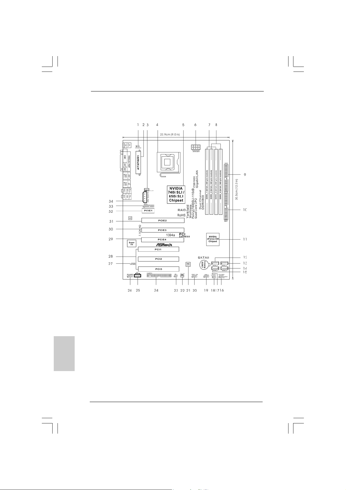
1 PS2_USB_PW1 Jumper 18 Chassis Speaker Header (SPEAKER 1)
2 ATX Power Connector (ATXPWR1) 19 USB 2.0 Header (USB4_5, Blue)
3 CPU Fan Connector (CPU_FAN1) 20 Front Panel IEEE 1394 Header
4 775-Pin CPU Socket (FRONT_1394)
5 North Bridge Controller 21 LPC
6 ATX 12V Power Connector (ATX12V1) 22 Chassis Fan Connector (CHA_FAN1)
7 2 x 240-pin DDR2 DIMM Slots 23 Infrared Module Header (IR1)
(Dual Channel A: DDRII_1, DDRII_3; Yellow) 24 Floppy Connector (FLOPPY1)
8 2 x 240-pin DD R2 DI MM Sl ots 25 Internal Audio Connector: CD1 (Black)
(Dual Channel B: DDRII_2, DDRII_4; Orange) 26 Front Panel Audio Header (HD_AUDIO1)
9 Secondary IDE Connector (IDE2, Black) 27 HDMI_SPDIF Header (HDMI_SPDIF1)
10 Primary IDE Connector (IDE1, Blue) 28 PCI Slots (PCI1- 3)
11 South Bridge Controller 29 PCI Express x8 Slot (PCIE4, Yellow)
12 Secondary SATAII Connector (SATAII_2) 30 PCI Express x16 Slot (PCIE3, White)
13 Fourth SATAII Connector (SATAII_4) 31 PCI Express x8 Slot (PCIE2, Yellow)
14 Third SATAII Connector (SATAII_3) 32 PCI Express x1 Slot (PCIE1, White)
15 Primary SATAII Connector (SATAII_1) 33 WiFi/E Header (WIFI/E)
16 System Panel Header (PANEL1) 34 SLI / XFIRE Power Connector
17 Clear CMOS Jumper (CLRCMOS1)
ASRock Penryn1600SLI-110dB Motherboard
Page 3
ASRock WiFi_SPDIF I/O PlusASRock WiFi_SPDIF I/O Plus
ASRock WiFi_SPDIF I/O Plus
ASRock WiFi_SPDIF I/O PlusASRock WiFi_SPDIF I/O Plus
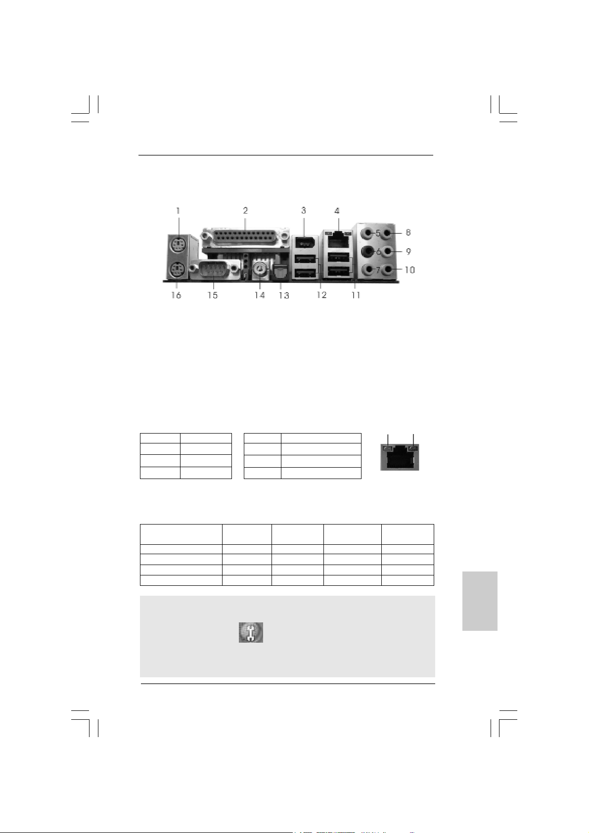
1 PS/2 Mouse Port (Green) ** 9 Front Speaker (Lime)
2 Parallel Port 10 Microphone (Pink)
3 IEEE 1394 Port 11 USB 2.0 Ports (USB01)
* 4 LAN RJ-45 Port 12 USB 2.0 Ports (USB23)
5 Side Speaker (Gray) 13 Optical SPDIF Out Port
6 Rear Speaker (Black) 14 Coaxial SPDIF Out Port
7 Central / Bass (Orange) 15 COM Port
8 Line In (Light Blue) 16 PS/2 Keyboard Port (Purple)
* There are two LED next to the LAN port. Please refer to the table below for the LAN port LED
indications.
Activity/Link LED SPEED LED
Status Description Status Description
LAN Port LED Indications
SPEED
LED
ACT/LINK
LED
Off No link Off 10Mbps connection
Orange Linked Orange 100Mbps connection
Blinking Data Activity Green 1Gbps connection
LAN Port
** If you use 2-channel speaker, please connect the speaker’s plug into “Front Speaker Jack”.
See the table below for connection details in accordance with the type of speaker you use.
TABLE f or Audio Output Connection
Audio Output ChannelsFront Speaker Rear Speaker Central / Bass Side Speaker
(No. 9) (No. 6) (No. 7) (No. 5)
2 V -- -- -4VV---6 VVV-8 VVVV
To enable Multi-Streaming function, you need to connect a front panel audio cable to the front
panel audio header. After restarting your computer, you will find “Mixer” tool on your system.
Please select “Mixer ToolBox” , click “Enable playback multi-streaming”, and click
“ok”. Choose “2CH”, “4CH”, “6CH”, or “8CH” and then you are allowed to select “Realtek HDA
Primary output” to use Rear Speaker, Central/Bass, and Front Speaker, or select “Realtek
HDA Audio 2nd output” to use front panel audio.
ASRock Penryn1600SLI-110dB Motherboard
EnglishEnglish
EnglishEnglish
English
33
3
33
Page 4
1. Introduction1. Introduction
1. Introduction
1. Introduction1. Introduction
Thank you for purchasing ASRock Penryn1600SLI-110dB motherboard, a reliable
motherboard produced under ASRock’s consistently stringent quality control. It delivers
excellent performance with robust design conf orming to ASRock’s commitment to quality and endurance.
This Quick Installation Guide contains introduction of the motherboard and step-bystep installation guide. More detailed information of the motherboard can be found in
the user manual presented in the Support CD.
Because the motherboard specifications and the BIOS software might be
updated, the content of this manual will be subject to change without
notice. In case any modifications of this manual occur, the updated
version will be available on ASRock website without further notice. You
may find the latest VGA cards and CPU support lists on ASRock website
as well. ASRock website http://www.asrock.com
If you require technical support related to this motherboard, please visit
our website for specific information about the model you are using.
www.asrock.com/support/index.asp
English
EnglishEnglish
EnglishEnglish
44
4
44
1.1 P1.1 P
1.1 P
1.1 P1.1 P
1 x ASRock Penryn1600SLI-110dB Motherboard
1 x ASRock SLI Bridge
1 x ASRock Penryn1600SLI-110dB Quick Installation Guide
1 x ASRock Penryn1600SLI-110dB Support CD
1 x Ultra A TA 66/100/133 IDE Ribbon Cable (80-conductor)
1 x 3.5-in Floppy Drive Ribbon Cable
4 x Serial AT A (SATA) Data Cables (Optional)
1 x Serial AT A (SAT A) HDD Power Cable (Option al)
1 x HDMI_SPDIF Cable (Optional)
1 x “ASRock WiFi_SPDIF I/O Plus” I/O Shield
ackack
age Contentsage Contents
ack
age Contents
ackack
age Contentsage Contents
(ATX Form Factor: 12.0-in x 9.0-in, 30.5 cm x 22.9 cm)
ASRock Penryn1600SLI-110dB Motherboard
Page 5
1.21.2
SpecificationsSpecifications
1.2
Specifications
1.21.2
SpecificationsSpecifications
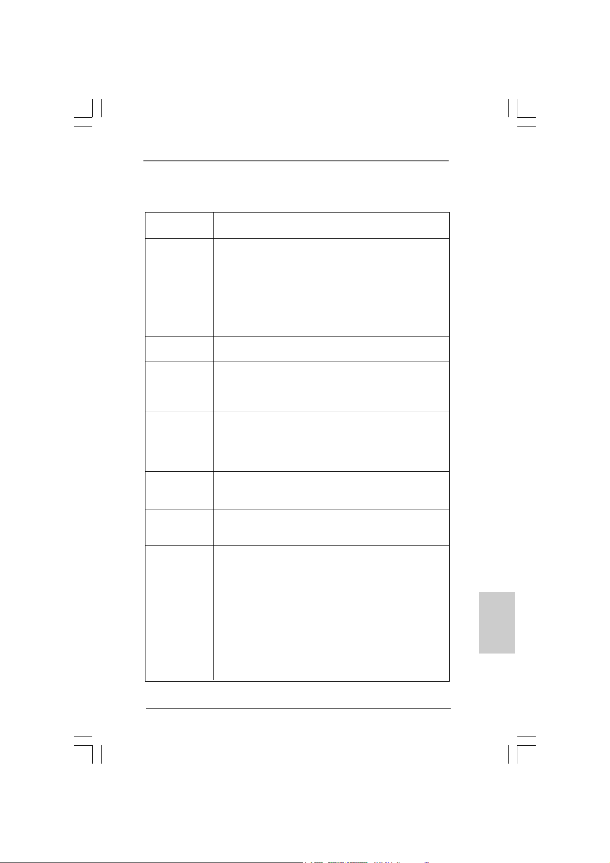
Platform - ATX Form Factor: 12.0-in x 9.0-in, 30.5 cm x 22.9 cm
- All Solid Capacitor design
CPU - LGA 775 for Intel® CoreTM 2 Extreme / CoreTM 2 Quad / Core
2 Duo / Pentium® Dual Core / Celeron®, supporting Penryn Quad
Core Y orkf ield a nd Dual Core Wolfdale processors
- Compatible with all FSB1600/1333/1066/800MHz CPUs
(see CAUTION 1)
- Supports Hyper-Threading Technology (see CAUTION 2)
- Supports Untied Overclocking Technology (see CAUTION 3)
- Supports EM64T CPU
Chipset - Northbridge: NVIDIA® 740i SLI / 650i SLI
- Southbridge: N VIDIA® nForce 430
Memory - Dual Channel DDR2 Memory T echnology (see CAUTION 4)
- 4 x DDR2 DIMM slots
- Support DDR2 800/667/533 non-ECC, un-buf fered memory
- Max. capacity of system memory: 8GB (see CAUTION 5)
Expansion Slot - 1 x PCI Express x16 slot (White)
- 2 x PCI Express x8 slots (Yellow; for NVIDIA
- 1 x PCI Express x1 slot
- 3 x PCI slots
- Supports NVIDIA® SLITM (see CAUTION 6)
Audio - 7.1 CH Windows® VistaTM Premium Level HD Audio with
Content Protection
- DAC with 110dB dynamic ra nge (ALC890 Audio Codec)
LAN - Gigabit LAN 10/100/1000 Mb/s
- Giga PHY Realtek RTL8211B
- Supports Wa ke-On-LAN
Rear Panel I/O ASRock WiFi_SDIF I/O Plus
- 1 x PS/2 Mouse Port
- 1 x PS/2 Keyboard Port
- 1 x Serial Port: COM1
- 1 x Parallel Port (ECP/EPP Support)
- 1 x Coaxial SPDIF Out Port
- 1 x Optical SPDIF Out Port
- 4 x Ready-to-Use USB 2.0 Port
- 1 x RJ-45 LAN Port
- 2 x RJ-45 LAN Port LED (ACT/LIN K LED a nd SPEED LED)
- 1 x IEEE 1394 Port
®
SLITM only)
TM
EnglishEnglish
EnglishEnglish
English
ASRock Penryn1600SLI-110dB Motherboard
55
5
55
Page 6
English
EnglishEnglish
EnglishEnglish
66
6
66
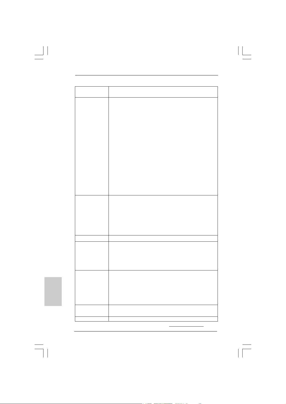
- HD Audio Jack: Side Speaker/Rear Spea ker/Central/Bass/
Line in/Front Speaker/Microphone (see CAUTION 7)
Connector - 4 x SATAII 3.0Gb/s connectors, support RAID (RAID 0, RAID 1,
RAID 0+1, RAID 5 a nd JBOD) a nd NCQ function s
(see CAUTION 8)
- 2 x ATA133 IDE connectors (support 4 x IDE device s)
- 1 x Floppy connector
- 1 x IR header
- 1 x HDMI_SPDIF header
- 1 x IEEE 1394 header
- CPU/Chassis FAN connector
- 24 pin A TX power conne ctor
- 8 pin 12V power connector
- SLI/XFIRE power connector
- CD in header
- Front panel audio connector
- 1 x USB 2.0 header (supports 2 USB 2.0 ports)
(see CAUTION 9)
- 1 x WiFi/E header (see CAUTION 10)
BIOS Feature - 8Mb AMI BIOS
- AMI Legal BIOS
- Supports “Plug and Play”
- ACPI 1.1 Compliance Wake Up Events
- Supports jumperfree
- AMBIOS 2.3.1 Support
- CPU, DRAM, NB, SB, VTT V oltage Multi-a djustment
Support CD - Drivers, Utilities, AntiVirus Software (Trial V ersion)
Unique Feature - ASRock OC Tuner (see CAUTION 11)
- Hybrid Booster:
- CPU Frequency Stepless Control (see CAUTION 12)
- ASRock U-COP (see CAUTION 13)
- Boot Failure Guard (B.F.G.)
Hardware - CPU T emperature Sensing
Monitor - Chassis Temperature Sensing
- CPU Fan Tachometer
- Chassis Fa n Tachometer
- CPU Quiet Fan
- Voltage Monitoring: +12V, +5V, +3.3V, CPU Vcore
OS - Microsoft® Windows® 2000 / XP / XP 64-bit / Vista
VistaTM 64-bit compliant
Certifications - FCC, CE, WHQL
* For detailed product information, please visit our website: http://www.asrock.com
ASRock Penryn1600SLI-110dB Motherboard
TM
/
Page 7

WA R NING
Please realize that there is a certain risk involved with overclocking, including
adjusting the setting in the BIOS, applying Untied Overclocking Technology, or using
the third-party overclocking tools. Overclocking may affect your system stability, or
even cause damage to the components and devices of your system. It should be
done at your own risk and expense. We are not responsible for possible damage
caused by overclocking.
CAUTION!
1. FSB1600-CPU will operate in overclocking mode.
2. About the setting of “Hyper Threading Technology”, please check page
40 of “User Manual” in the support CD.
3. This motherboard supports Untied Overclocking Technology. Please read
“Untied Overclocking Technology” on page 31 for details.
4. This motherboard supports Dual Channel Memory Technology. Before
you implement Dual Channel Memory Technology, make sure to read
the installation guide of memory modules on page 13 for proper
installation.
5. Due to the operating system limitation, the actual memory size may be
less than 4GB for the reservation for system usage under Windows® XP
and Windows® VistaTM. For Windows® XP 64-bit and Windows® Vista
64-bit with 64-bit CPU, there is no such limitation.
6. This motherboard supports NVIDIA® SLITM technology. PCIE2 and PCIE4
slots (yellow) are intended for SLI
PCI Express VGA card to this motherboard, please install it to PCIE3 slot.
For the information of the compatible SLITM Mode PCI Express VGA cards,
please refer to the “Supported PCI Express VGA Card List for SLITM Mode”
on page 9. For the proper installation of PCI Express VGA card, please refer
to the installation guide on page 15.
7. For microphone input, this motherboard supports both stereo and mono
modes. For audio output, this motherboard supports 2-channel, 4channel, 6-channel, and 8-channel modes. Please check the table on
page 3 for proper connection.
8. Before installing SATAII hard disk to SATAII connector, please read the
“SATAII Hard Disk Setup Guide” on page 27 to adjust your SATAII hard
disk drive to SATAII mode. You can also connect SA TA hard disk to SATAII
connector directly.
9. Power Management for USB 2.0 works fine under Microsoft® Windows
VistaTM 64-bit / VistaTM / XP 64-bit / XP SP1 or SP2 / 2000 SP4.
10. WiFi/E header supports WiFi+AP function with ASRock WiFi-802.11g or
WiFi-802.11n module, an easy-to-use wireless local area network
(WLAN) adapter. It allows you to create a wireless environment and
enjoy the convenience of wireless network connectivity. Please visit our
website for the availability of ASRock WiFi-802.11g or WiFi-802.11n
module. ASRock website http://www.asrock.com
TM
function. If you plan to install only one
TM
®
EnglishEnglish
EnglishEnglish
English
ASRock Penryn1600SLI-110dB Motherboard
77
7
77
Page 8
11. It is a user-friendly ASRock overclocking tool which allows you to surveil
your system by hardware monitor function and overclock your hardware
devices to get the best system performance under Windows
environment. Please visit our website for the operation procedures of
ASRock OC Tuner. ASRock website: http://www.asrock.com
12. Although this motherboard offers stepless control, it is not recommended to perform over-clocking. Frequencies other than the recommended CPU bus frequencies may cause the instability of the system
or damage the CPU.
13. While CPU overheat is detected, the system will automatically shutdown.
Before you resume the system, please check if the CPU fan on the
motherboard functions properly and unplug the power cord, then plug it
back again. To improve heat dissipation, remember to spray thermal
grease between the CPU and the heatsink when you install the PC
system.
1.31.3
Minimum Hardware RMinimum Hardware R
1.3
Minimum Hardware R
1.31.3
Minimum Hardware RMinimum Hardware R
TMTM
TM
TMTM
VistaVista
Vista
VistaVista
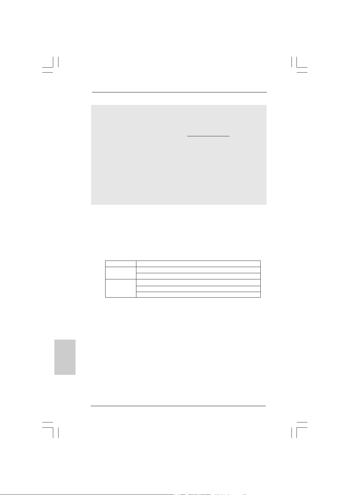
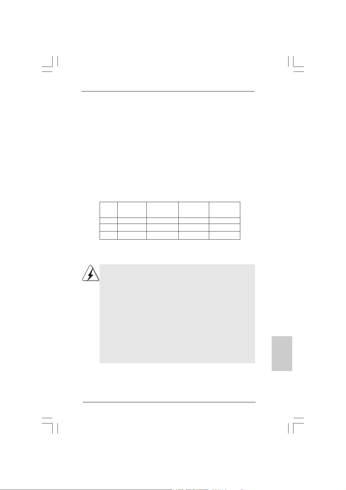
For system integrators and users who purchase this motherboard and
plan to submit Windows® VistaTM Premium 2008 and Basic logo, please
follow below table for minimum hardware requirements.
CPU Celeron 420
Memory 1GB system memory (Premium)
VGA DX10.0 with WDDM Driver
Premium 2008 and Basic Logo Premium 2008 and Basic Logo
Premium 2008 and Basic Logo
Premium 2008 and Basic Logo Premium 2008 and Basic Logo
512MB Single Channel (Basic)
with 128bit VGA memory (Premium)
with 64bit VGA memory (Basic)
equirement Tequirement T
equirement T
equirement Tequirement T
able for Wable for W
able for W
able for Wable for W
®
indowsindows
indows
indowsindows
®®
®
®®
English
EnglishEnglish
EnglishEnglish
88
8
88
* After June 1, 2008, all Windows® VistaTM systems are required to meet above
minimum hardware requirements in order to qualify for Windows® VistaTM Premium
2008 logo.
ASRock Penryn1600SLI-110dB Motherboard
Page 9
1.41.4
Supported PCI Express VGA Card List for SLISupported PCI Express VGA Card List for SLI
1.4
Supported PCI Express VGA Card List for SLI
1.41.4
Supported PCI Express VGA Card List for SLISupported PCI Express VGA Card List for SLI
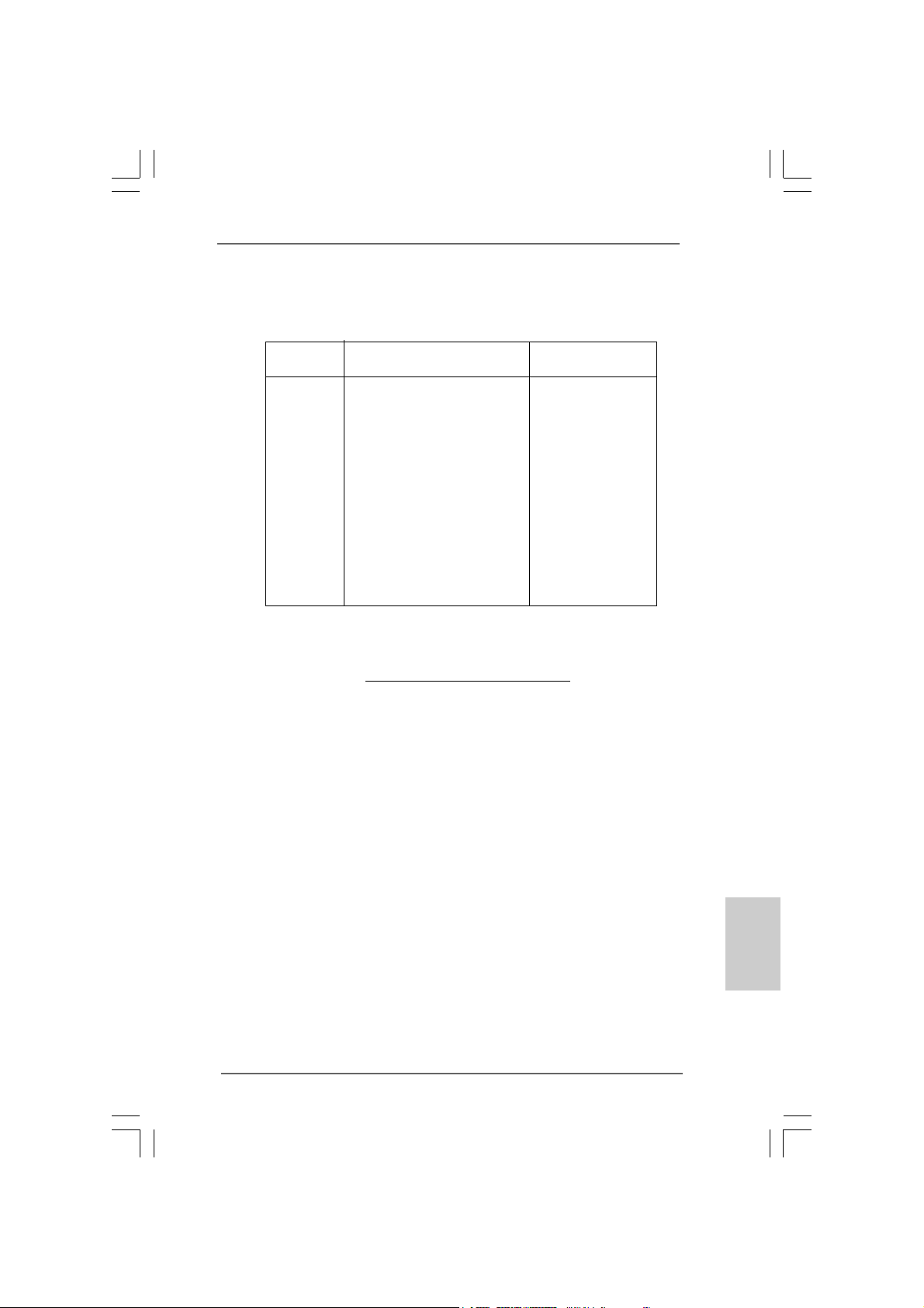
(for Windows® XP / XP 64-bit / VistaTM / VistaTM 64-bit only)
Graphics Chip Model Name Chipset Name
Vendor
NVIDIA
ASUS EN8800GTX
ASUS EN8600GT/2DHT
ASUS EN7950GX2 *
ASUS EN7900GT TOP
ASUS EN7800GT
ASUS EN7600GSSILENT
ASUS EN7600GT/2DHT
ASUS EN6800LE
ASUS Extreme N6800/TD
ALBATRON PC6600GT
GIGABYTE GV -NX66256DP2
LEADTEK PX7900GS TDH
LEADTEK PX7300GS TDH *
MSI 7300GT-TD256EH
TMTM
TM
TMTM
GeForce 8800GTX
GeForce 8600GT
GeForce 7950GX2
GeForce 7900GT
GeForce 7800GT
GeForce 7600GT
GeForce 7600GS
GeForce 6800LE
GeForce 6800
GeForce 6600GT
GeForce 6600
GeForce 7900GS
GeForce 7300GS
GeForce 7300GT
Mode Mode
Mode
Mode Mode
* These two cards can only work under Windows
For the latest updates of the supported PCI Express VGA card list for SLITM Mode,
please visit our website for details.
ASRock website:
http://www.asrock.com/support/index.htm
®
XP / XP 64-bit OS.
ASRock Penryn1600SLI-110dB Motherboard
EnglishEnglish
EnglishEnglish
English
99
9
99
Page 10
2.2.
InstallationInstallation
2.
Installation
2.2.
InstallationInstallation
Pre-installation PrecautionsPre-installation Precautions
Pre-installation Precautions
Pre-installation PrecautionsPre-installation Precautions
Take note of the following precautions before you install motherboard components or change any motherboard settings.
1. Unplug the power cord from the wall socket before touching any
component. Failure to do so may cause severe damage to the
motherboard, peripherals, and/or components.
2. To avoid damaging the motherboard components due to static
electricity, NEVER place your motherboard directly on the carpet
or the like. Also remember to use a grounded wrist strap or touch
a safety grounded object before you handle components.
3. Hold components by the edges and do not touch the ICs.
4. Whenever you uninstall any component, place it on a grounded
antstatic pad or in the bag that comes with the component.
5. When placing screws into the screw holes to secure the
motherboard to the chassis, please do not over-tighten the
screws! Doing so may damage the motherboard.
2.12.1
CPU InstallationCPU Installation
2.1
CPU Installation
2.12.1
CPU InstallationCPU Installation
For the installation of Intel 775-LAND CPU,
please follow the steps below.
English
EnglishEnglish
EnglishEnglish
1010
10
1010
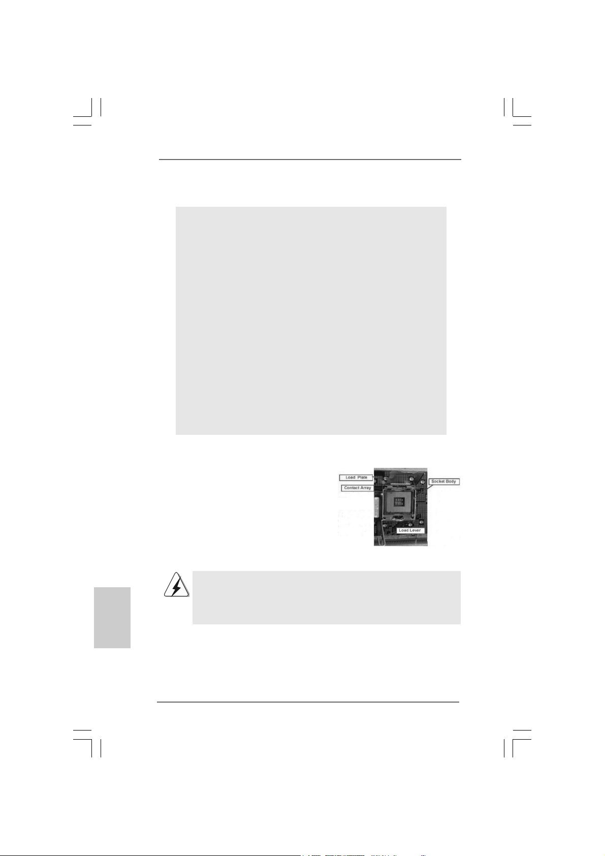
775-Pin Socket Overview
Before you insert the 775-LAND CPU into the socket, please check if
the CPU surface is unclean or if there is any bent pin on the socket.
Do not force to insert the CPU into the socket if above situation is
found. Otherwise, the CPU will be seriously damaged.
ASRock Penryn1600SLI-110dB Motherboard
Page 11
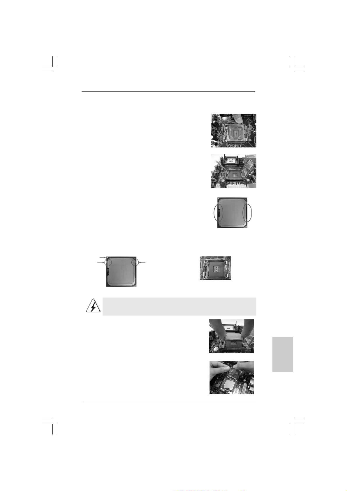
Step 1. Open the socket:
Step 1-1. Disengaging the lever by depressing
down and out on the hook to clear
retention tab.
Step 1-2. Rotate the load lever to fully open po-
sition at approximately 135 degrees.
Step 1-3. Rotate the load plate to fully open po-
sition at approximately 100 degrees.
Step 2. Insert the 775-LAND CPU:
Step 2-1. Hold the CPU by the edges where are
marked with black lines.
Step 2-2. Orient the CPU with IHS (Integrated
Heat Sink) up. Locate Pin1 and the two
orientation key notches.
Pin1
orientation
key notch
orientation
key notch
Pin1
alignment key
black line
black line
alignment key
775-LAND CPU
For proper inserting, please ensure to match the two orientation key
notches of the CPU with the two alignment keys of the socket.
Step 2-3. Carefully pla ce the CPU into the socket
by using a purely vertical motion.
Step 2-4. Verify that the CPU is within the socket
and properly mated to the orient keys.
Step 3. Remove PnP Cap (Pick and Pla ce Cap):
Use your left hand index finger and thumb to
support the load plate edge, engage PnP cap
with right hand thumb and peel the cap from the
socket while pressing on center of PnP cap to
assist in removal.
ASRock Penryn1600SLI-110dB Motherboard
775-Pin Socket
1111
11
1111
EnglishEnglish
EnglishEnglish
English
Page 12
1. It is recommended to use the cap tab to handle and avoid kicking
off the PnP cap.
2. This cap must be placed if returning the motherboard for after
service.
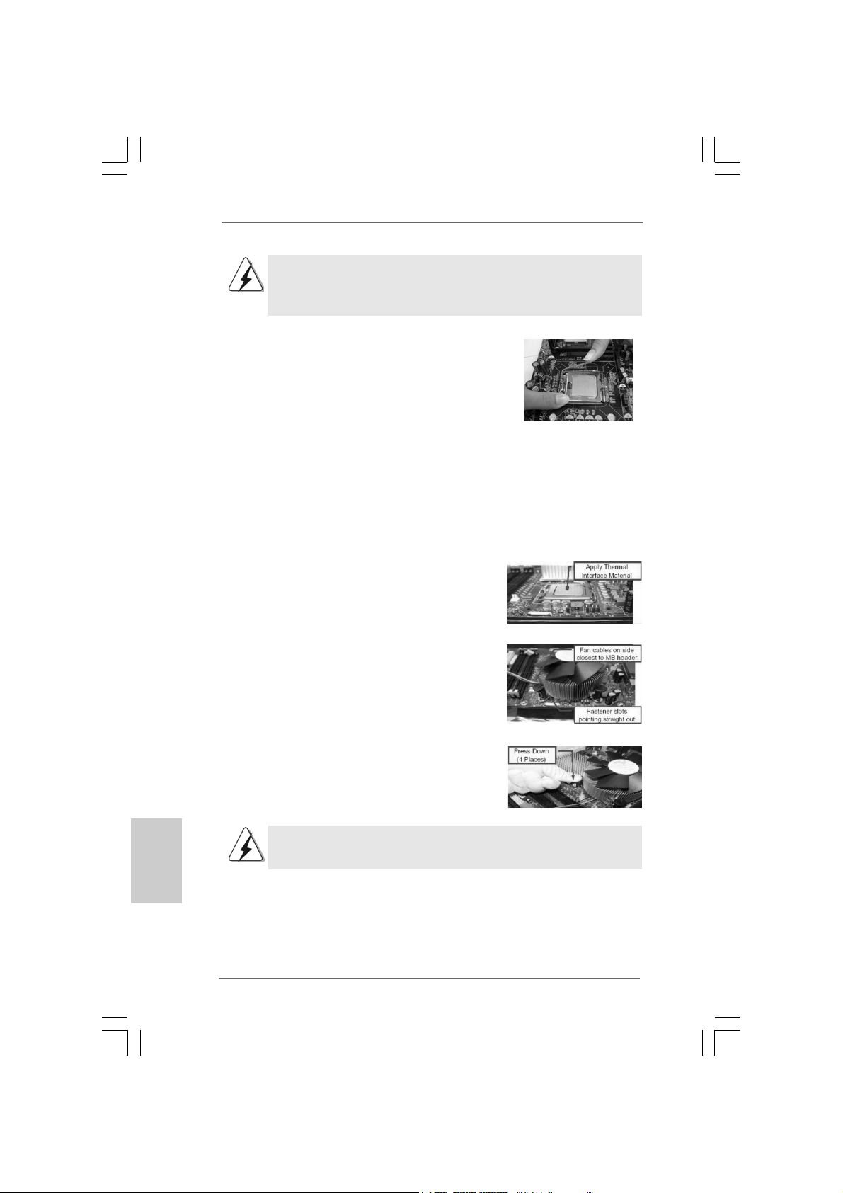
Step 4. Close the socket:
Step 4-1. Rotate the load plate onto the IHS.
Step 4-2. While pressing down lightly on load
plate, engage the load lever.
Step 4-3. Secure load lever with load plate tab
under retention tab of load lever.
2.22.2
Installation of CPU Fan and HeatsinkInstallation of CPU Fan and Heatsink
2.2
Installation of CPU Fan and Heatsink
2.22.2
Installation of CPU Fan and HeatsinkInstallation of CPU Fan and Heatsink
For proper installation, please kindly refer to the instruction manuals of your CPU fan
and heatsink.
Below is an example to illustrate the installation of the heatsink for 775-LAND CPU.
Step 1. Apply thermal interface material onto center
of IHS on the socket surface.
Step 2. Place the heatsink onto the socket. Ensure
fan cables are oriented on side closest to the
CPU fan connector on the motherboard
(CPU_FAN1, see page 2, No. 3).
Step 3. Align fasteners with the motherboard
throughholes.
Step 4. Rotate the fastener clockwise, then press
down on fastener caps with thumb to install
and lock. Repeat with remaining fasteners.
English
EnglishEnglish
EnglishEnglish
1212
12
1212
If you press down the fasteners without rotating them clockwise,
the heatsink cannot be secured on the motherboard.
Step 5. Connect fan header with the CPU fan
connector on the motherboard.
Step 6. S ecure excess cable with tie-wrap to ensure
cable does not interfere with fan operation or
contact other components.
ASRock Penryn1600SLI-110dB Motherboard
Page 13
2.3 Installation of Memor2.3 Installation of Memor
2.3 Installation of Memor
2.3 Installation of Memor2.3 Installation of Memor
This motherboard provides four 240-pin DDR2 (Double Data Rate 2) DIMM slots,
and supports Dual Channel Memory Technology. For dual channel configuration,
you always need to install identical (the same brand, speed, size and chip-type)
DDR2 DIMM pair in the slots of the same color. In other words, you have to install
identical DDR2 DIMM pair in Dual Cha nnel A (DDRII_1 a nd DDRII_3; Yellow slots;
see p.2 No.7) or identical DDR2 DIMM pair in Dual Channel B (DDRII_2 and
DDRII_4; Orange slots; see p.2 No.8), so that Dual Channel Me mory Technology
can be a ctivated. This motherboard also allows you to install f our DD R2 DIMMs f or
dual channel configuration, and please install identical DDR2 DIMMs in all four
slots. Y ou may refer to the Dual Channel Memory Configuration Table below.
Dual Channel Memory Configurations
DDRII_1 DDRII_2 DDRII_3 DDRII_4
(Y ellow Slot) (Orange Slot) (Y ellow Slot) (Orange Slot)
(1) Populated - Populated (2) - Populated - Populated
(3)* Populated Populated Populated Populated
y Modules (DIMM)y Modules (DIMM)
y Modules (DIMM)
y Modules (DIMM)y Modules (DIMM)
* For the configuration (3), please install identical DDR2 DIMMs in all four slots.
1. If you want to install two memory modules, for optimal compatibility and reliability, it is recommended to install them in the slots of
the same color. In other words, install them either in the set of
yellow slots (DDRII_1 and DDRII_3), or in the set of orange slots
(DDRII_2 and DDRII_4).
2. If only one memory module or three memory modules are installed in the DDR2 DIMM slots on this motherboard, it is unable to
activate the Dual Channel Memory Technology.
3. If a pair of memory modules is NOT installed in the same Dual
Channel, for example, installing a pair of memory modules in
DDRII_1 and DDRII_2, it is unable to activate the Dual Channel
Memory Technology .
4. It is not allowed to install a DDR memory module into DDR2 slot;
otherwise, this motherboard and DIMM may be damaged.
EnglishEnglish
EnglishEnglish
English
ASRock Penryn1600SLI-110dB Motherboard
1313
13
1313
Page 14
Installing a DIMMInstalling a DIMM
Installing a DIMM
Installing a DIMMInstalling a DIMM
Please make sure to disconnect power supply before adding or
removing DIMMs or the system components.
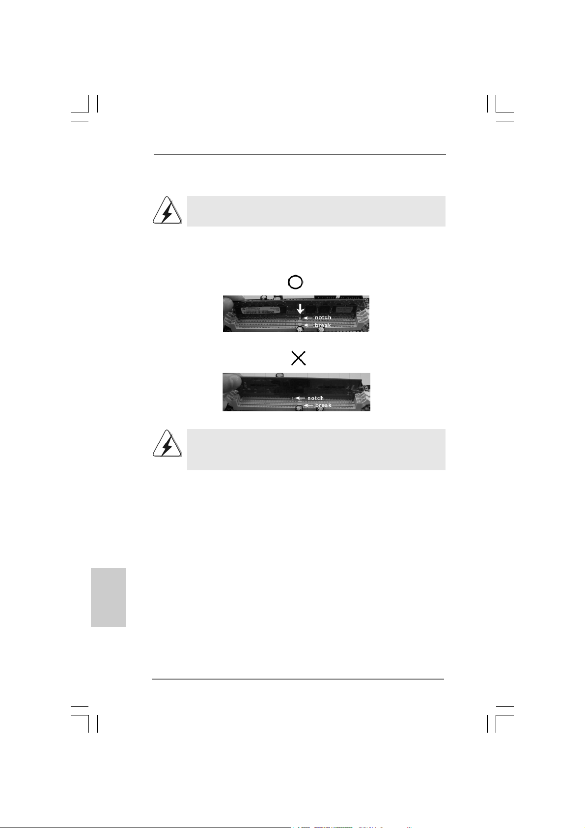
Step 1. U nlock a DIMM slot by pressing the retaining clips outward.
Step 2. Align a DIMM on the slot such that the notch on the DIMM matches the bre a k
on the slot.
The DIMM only fits in one correct orientation. It will cause permanent
damage to the motherboard and the DIMM if you force the DIMM into the slot
at incorrect orientation.
English
EnglishEnglish
EnglishEnglish
1414
14
1414
Step 3. Firmly insert the DIMM into the slot until the retaining clips at both ends fully
sna p back in place and the DIMM is properly seated.
ASRock Penryn1600SLI-110dB Motherboard
Page 15
2.4 Expansion Slots (PCI and PCI Express Slots)2.4 Expansion Slots (PCI and PCI Express Slots)
2.4 Expansion Slots (PCI and PCI Express Slots)
2.4 Expansion Slots (PCI and PCI Express Slots)2.4 Expansion Slots (PCI and PCI Express Slots)
There are 3 PCI slots and 4 PCI Express slots on this motherboard.
PCI Slots: PCI slots are used to install expansion cards that have the 32-bit PCI
interface.
PCIE Slots:
PCIE1 (PCIE x1 slot) is used for PCI Express cards with x1 la ne width
cards, such as Gigabit LAN card, SATA2 card, etc.
PCIE2 / PCIE4 (PCIE x8 slot) is used to install PCI Express expansion
cards to support SLITM function. For the information of the compatible
SLITM Mode PCI Express V GA cards, please refer to the “Supported PCI
Express VGA Card List for SLITM Mode” on page 9.
PCIE3 (PCIE x16 slot) is used for PCI Express cards with x16 lane
width graphics cards.
1. This motherboard supports NVIDIA® SLITM technology. PCIE2 and
PCIE4 slots (yellow) are intended for SLITM function only. It is not
recommended to install other graphics cards on PCIE2 and PCIE4
slots, and we do not guarantee that your graphics cards can work
successfully under this situation.
2. You can only choose to use either PCIE3 slot or PCIE2 / PCIE4 slot
on this motherboard. If you plan to install only one PCI Express VGA
card to this motherboard, please install it to PCIE3 slot.
Installing an expansion cardInstalling an expansion card
Installing an expansion card
Installing an expansion cardInstalling an expansion card
Step 1. Before installing the expansion card, please make sure that the power
supply is switched off or the power cord is unplugged. Plea se re a d the
documentation of the expansion card a nd ma ke necessary hardware
settings for the card before you start the installation.
Step 2. Remove the system unit cover (if your motherboard is already installed in a
chassis).
Step 3. Remove the bracket fa cing the slot that you intend to use. Keep the screws
for later use.
Step 4. Align the card connector with the slot and press firmly until the card is
completely seated on the slot.
Step 5. Fasten the card to the chassis with screws.
Step 6. Replace the system cover .
EnglishEnglish
EnglishEnglish
English
ASRock Penryn1600SLI-110dB Motherboard
1515
15
1515
Page 16
TMTM
TM
2.5 SLI2.5 SLI
2.5 SLI
2.5 SLI2.5 SLI
TMTM
Operation Guide Operation Guide
Operation Guide
Operation Guide Operation Guide
This motherboard supports N VIDIA® SLITM (Scalable Link Interface) technology that allows
you to install two identical NVIDIA® SLI
TM
enabled PCI Express x16 gra phics
cards. Currently, NVIDIA® SLITM technology supports Windows® XP, XP 64-bit, Vista
and VistaTM 64-bit OS. Please follow the installation procedures in this section.
TM
SLI
Technology Requirements
1. You should have two identical SLITM-ready graphics cards that are NVIDIA
certified.
2. Make sure that your graphics card driver supports the NVIDIA® SLI
technology. Download the latest driver from the NVIDIA® website
(www.nvidia.com).
3. Make sure that your power supply unit (PSU) can provide at least the
minimum power required by your system.
TMTM
TM
Enjoy the benefit of SLIEnjoy the benefit of SLI
Enjoy the benefit of SLI
Enjoy the benefit of SLIEnjoy the benefit of SLI
TMTM
®
TM
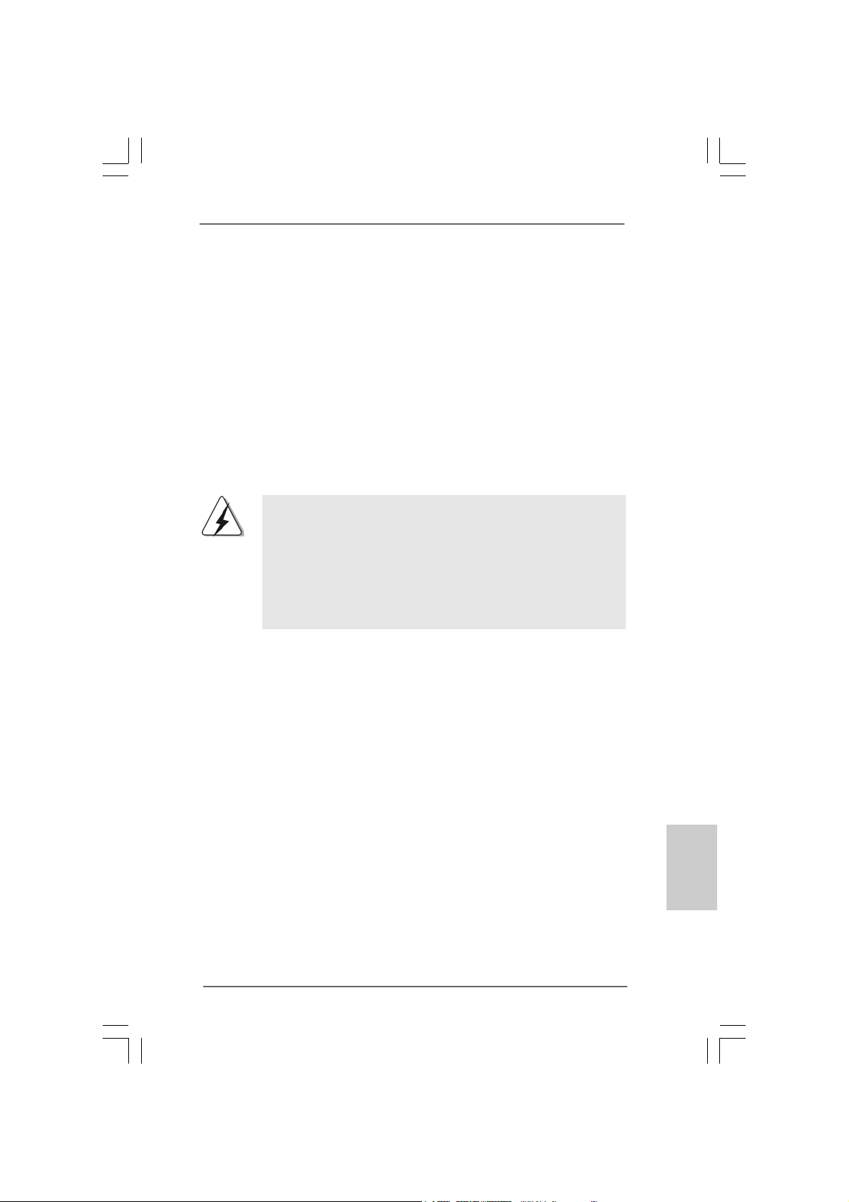
Step 1. Install the identical SLITM-ready gra phics cards that are NVIDIA® certified be-
cause different types of gra phics cards will not work together properly. (Even
the GPU chi ps version shall be the sa me.) Insert one gra phics card into PCIE2
slot and another graphics card to PCIE4 slot. Make sure that the cards are
properly seated on the slots.
TM
English
EnglishEnglish
EnglishEnglish
1616
16
1616
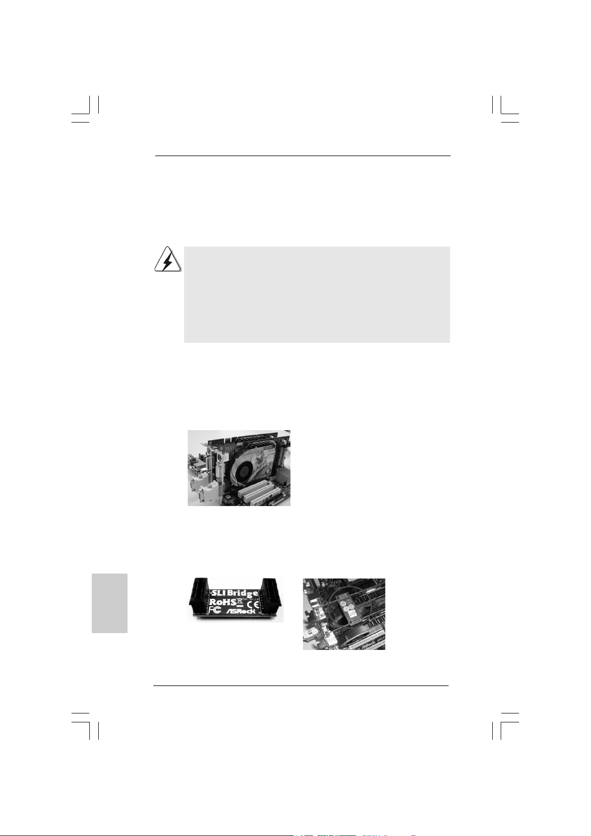
Step2. If required, connect an auxiliary power source to the PCI Express graphics
cards.
Step3. Align and insert the SLI Bridge to the goldfingers on ea ch graphics card. Make
sure that the SLI Bridge is firmly in place.
ASRock Penryn1600SLI-110dB Motherboard
Page 17
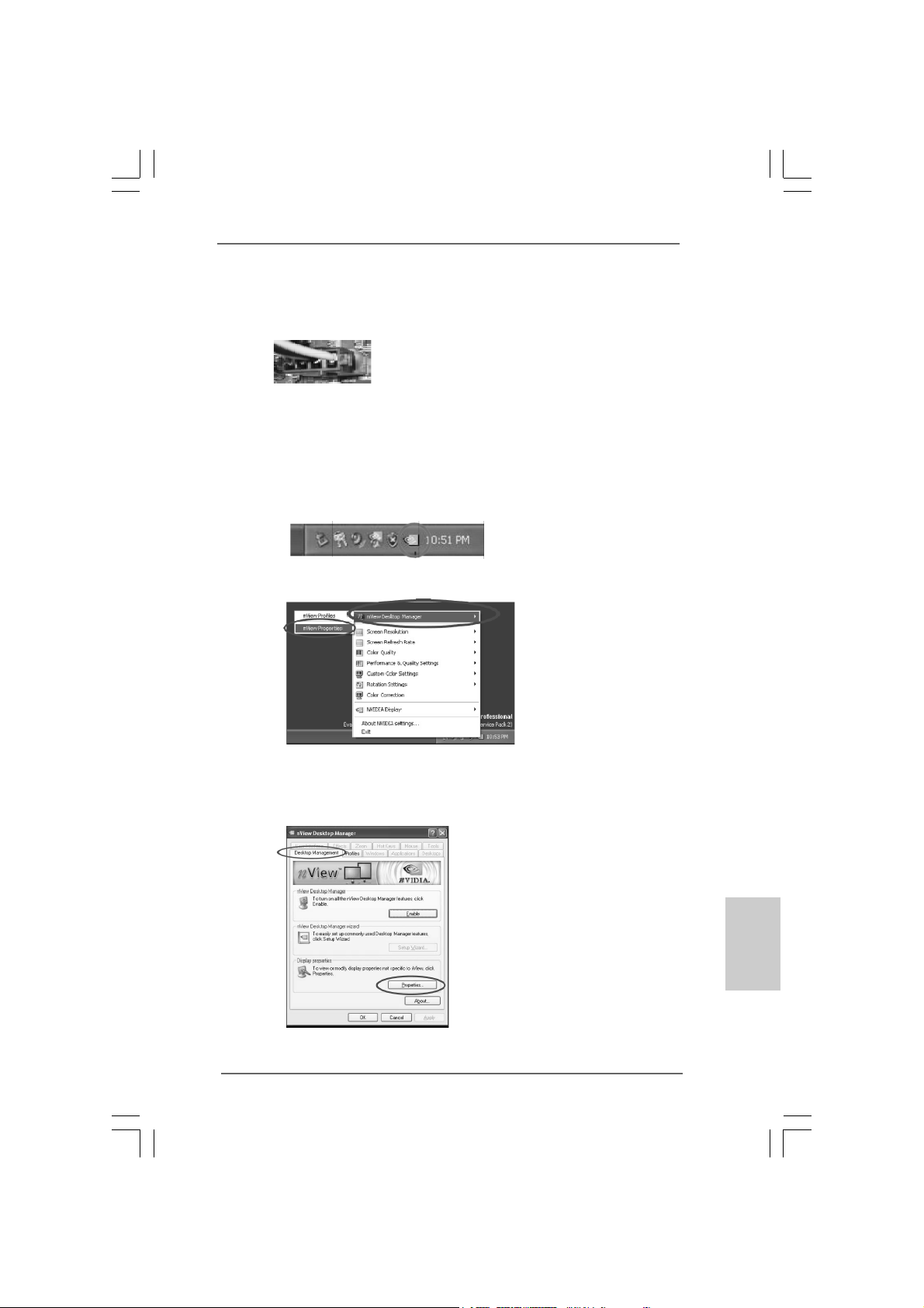
Step4. Connect a VGA cable or a DVI-I cable to the monitor connector and the DVI
connector of the graphics card that is in serted to PCIE2 slot.
Step5. Connect a 4-pin A TX power cable to SLI/XFIRE power conne ctor .
Step6. Install the graphics card drivers to your system. After that, you can enable the
Multi-Graphics Processing Unit (GPU) feature in the NVIDIA® nView
system tray utility. Please follow the below procedures to enable the multiGPU feature.
For Windows® XP / XP 64-bit OS:
A. Click the NVIDIA Settings icon on your Windows® taskbar.
B. From the pop-up menu, select nView Des ktop Man ager, and then
click nView Properties.
C. From the nView Desktop M anager window, select the Desktop
Management tab.
D. Click Properties to display the Display Propertie s dialog box.
ASRock Penryn1600SLI-110dB Motherboard
1717
17
1717
EnglishEnglish
EnglishEnglish
English
Page 18
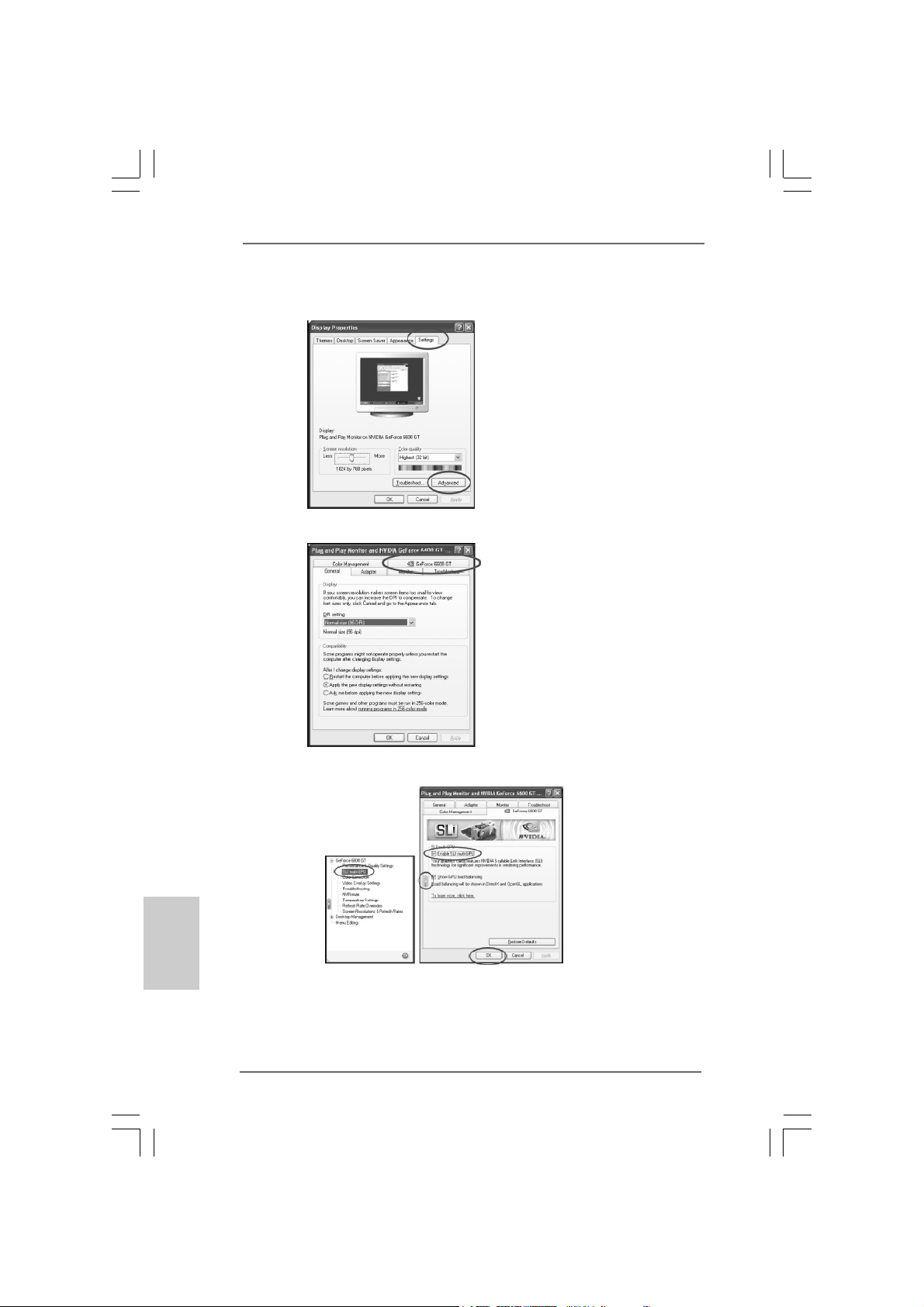
E. From the Display Properties dialog box, sele ct the Settings ta b then click
Advanced.
F. Select the NVIDIA GeForce tab.
English
EnglishEnglish
EnglishEnglish
1818
18
1818
G. Click the slider to display the following screen, then select the SLI
multi-GPU item.
H. Click the Enable SLI multi-GPU check box.
I. Click OK when done.
ASRock Penryn1600SLI-110dB Motherboard
Page 19
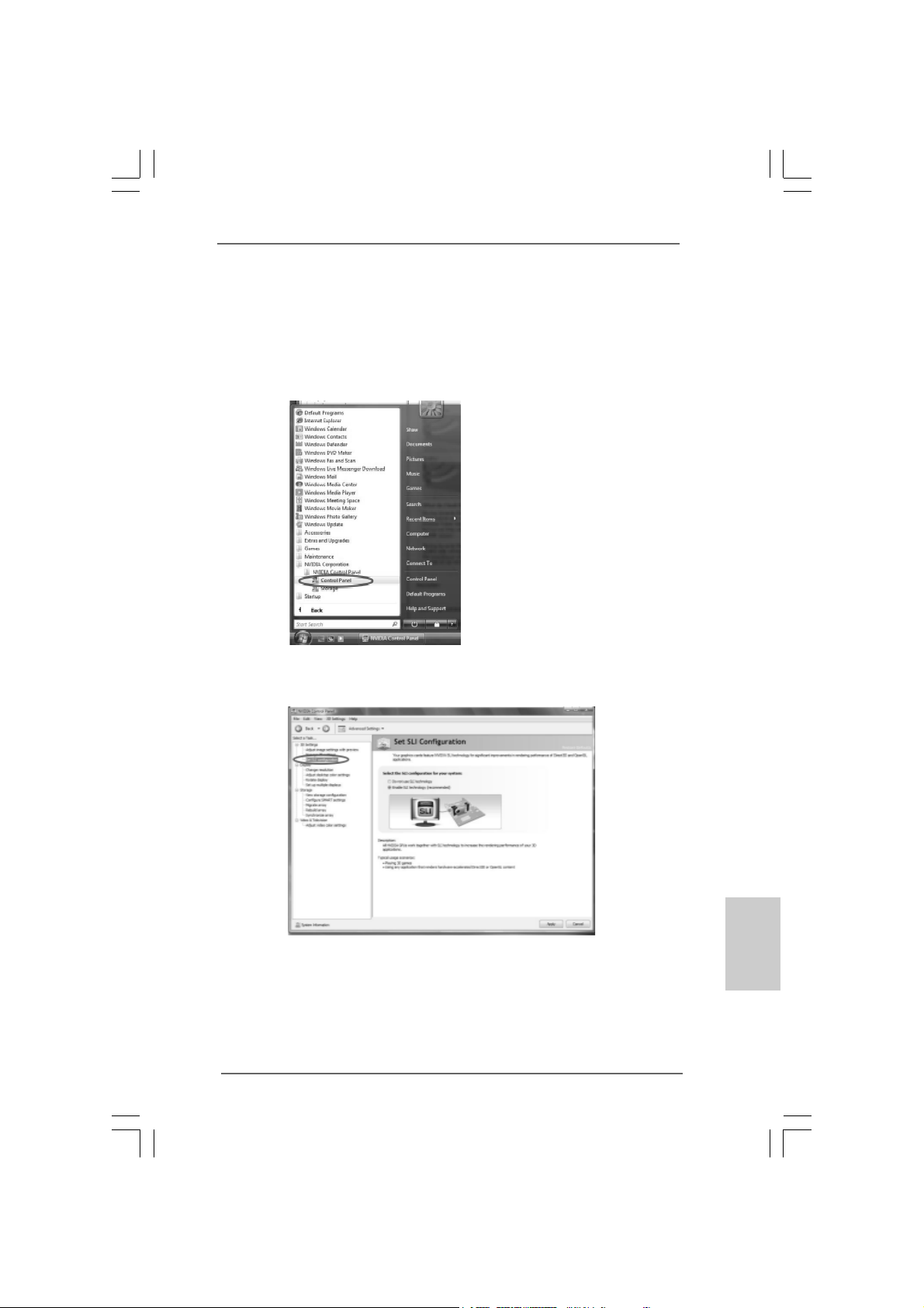
For Windows® VistaTM / VistaTM 64-bit OS:
A. Click the Start icon on your Windows taskbar.
B. From the pop-up menu, select All Programs, and then click NVIDIA
Corporation.
C. Select NVIDIA Control Panel tab.
D. Select Control Panel tab.
E. From the pop-up menu, select Set SLI configuration, and then click
Apply.
* SLITM appearing here is a registered trademark of NVIDIA® Technologies Inc., and is used
only for identification or explanation and to the owners’ benefit, without intent to infringe.
ASRock Penryn1600SLI-110dB Motherboard
1919
19
1919
EnglishEnglish
EnglishEnglish
English
Page 20
2.6 Surround Display Feature2.6 Surround Display Feature
2.6 Surround Display Feature
2.6 Surround Display Feature2.6 Surround Display Feature
This motherboard supports Surround Display upgrade. With the external add-on PCI
Express VGA card, you can e asily enjoy the benefits of Surround Display feature. For
the detailed instruction, plea se refer to the document at the f ollowing path in the
Support CD:
..\ Surround Display Information
2.7 Jumpers Setup2.7 Jumpers Setup
2.7 Jumpers Setup
2.7 Jumpers Setup2.7 Jumpers Setup
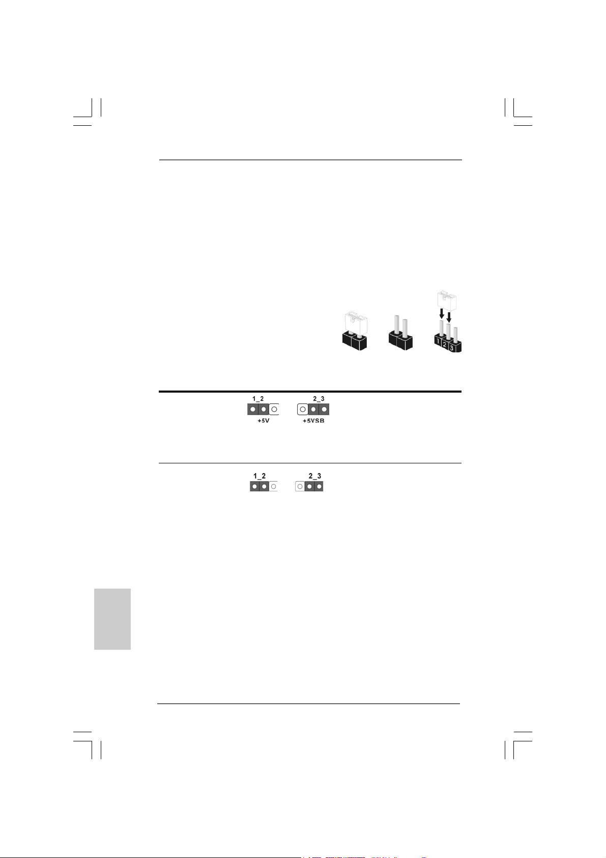
The illustration shows how jumpers are
setup. When the jumper cap is placed on
pins, the jumper is “Short”. If no jumper cap
is placed on pins, the jumper is “Open”. The
illustration shows a 3-pin jumper whose pin1
and pin2 are “Short” when jumper cap is
placed on these 2 pins.
Jumper Setting Description
PS2_USB_PWR1 Short pin2, pin3 to enable
(see p.2 No. 1) +5VSB (standby) for PS/2
Note: To select +5VSB, it requires 2 Amp and higher standby current provided by
power supply.
Clear CMOS Jumper
(CLRCMOS1)
(see p.2 No. 17)
Clear CMOSDefault
Short Open
or USB wake up events.
English
EnglishEnglish
EnglishEnglish
2020
20
2020
Note: CLRCMOS1 allows you to clear the data in CMOS. The data in CMOS includes
system setup information such as system password, date, time, and system
setup parameters. To clear and reset the system parameters to default setup,
please turn of f the computer and unplug the power cord from the power supply.
After waiting for 15 seconds, use a jumper ca p to short pin2 and pin3 on CLRCMOS1
for 5 seconds. However , please do not clear the CMOS right after you update the
BIOS. If you need to clear the CMOS when you just finish updating the BIOS, you
must boot up the system first, and then shut it down before you do the clearCMOS action.
ASRock Penryn1600SLI-110dB Motherboard
Page 21
2.8 Onboard Headers and Connectors2.8 Onboard Headers and Connectors
2.8 Onboard Headers and Connectors
2.8 Onboard Headers and Connectors2.8 Onboard Headers and Connectors
Onboard headers and connectors are NOT jumpers. Do NOT place
jumper caps over these headers and connectors. Placing jumper
caps over the headers and connectors will cause permanent damage of the motherboard!
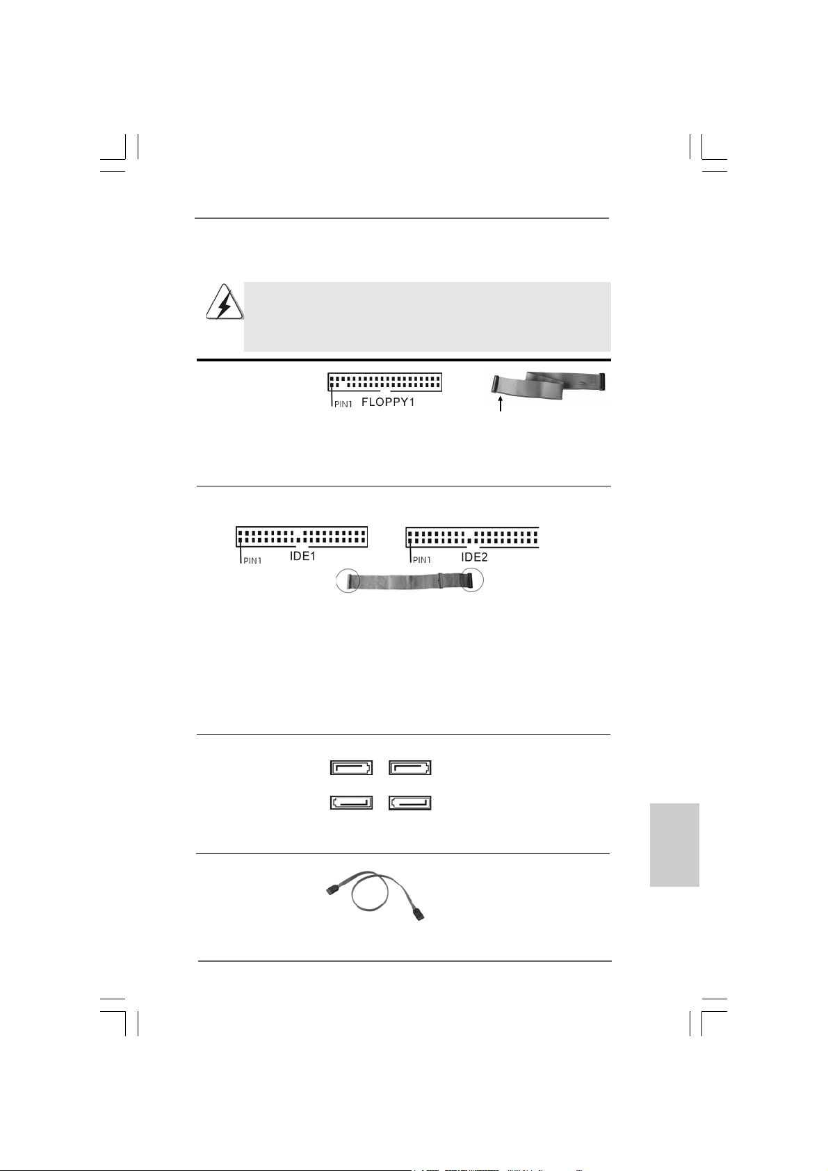
F DD conne ctor
(33-pin FLOPPY1)
(see p.2 No. 24)
the red-striped side to
Pin1
Note: Ma ke sure the red-striped side of the cable is plugged into Pin1 side of the
connector.
Primary IDE Connector (Blue) Secondary IDE Connector (Bla ck)
(39-pin IDE1, see p.2 No. 10) (39-pin IDE2, see p.2 No. 9)
connect the blue end
to the motherboard
connect the black end
to the IDE devices
80-conductor A TA 66/100/133 cable
Note: If you use only one IDE device on this motherboard, please set the IDE
device as “M a ster”. Ple a se refer to the in struction of your IDE device vendor
for the details. Besides, to optimize compatibility and performance, please
connect your hard disk drive to the primary IDE connector (IDE1, blue) a nd
CD-ROM to the secondary IDE connector (IDE2, black).
Serial A TAII Connectors These four Serial AT AII (SAT AII)
(SATAII_1: see p.2, No. 15) connectors support SA TA data
(SATAII_2: see p.2, No. 12) cables for internal storage
(SATAII_3: see p.2, No. 14) devices. The current SA T AII
(SATAII_4: see p.2, No. 13) interface allows up to 3.0 Gb/s
SATAII_2 SATAII_4
SATAII_1 SATAII_3
data transfer rate.
Serial ATA (SATA) Either end of the SATA data ca ble
Data Cable can be connected to the SATA /
(Optional) SATAII hard disk or the SA TAII
connector on this motherboard.
ASRock Penryn1600SLI-110dB Motherboard
2121
21
2121
EnglishEnglish
EnglishEnglish
English
Page 22
Serial ATA (SAT A) Plea se connect the black end of
Power Cable SAT A power ca ble to the power
(Optional) connector on each drive. Then
connect to the SATA
HDD power connector
connect to
the power
supply
connect the white end of SATA
power cable to the power
connector of the power supply.
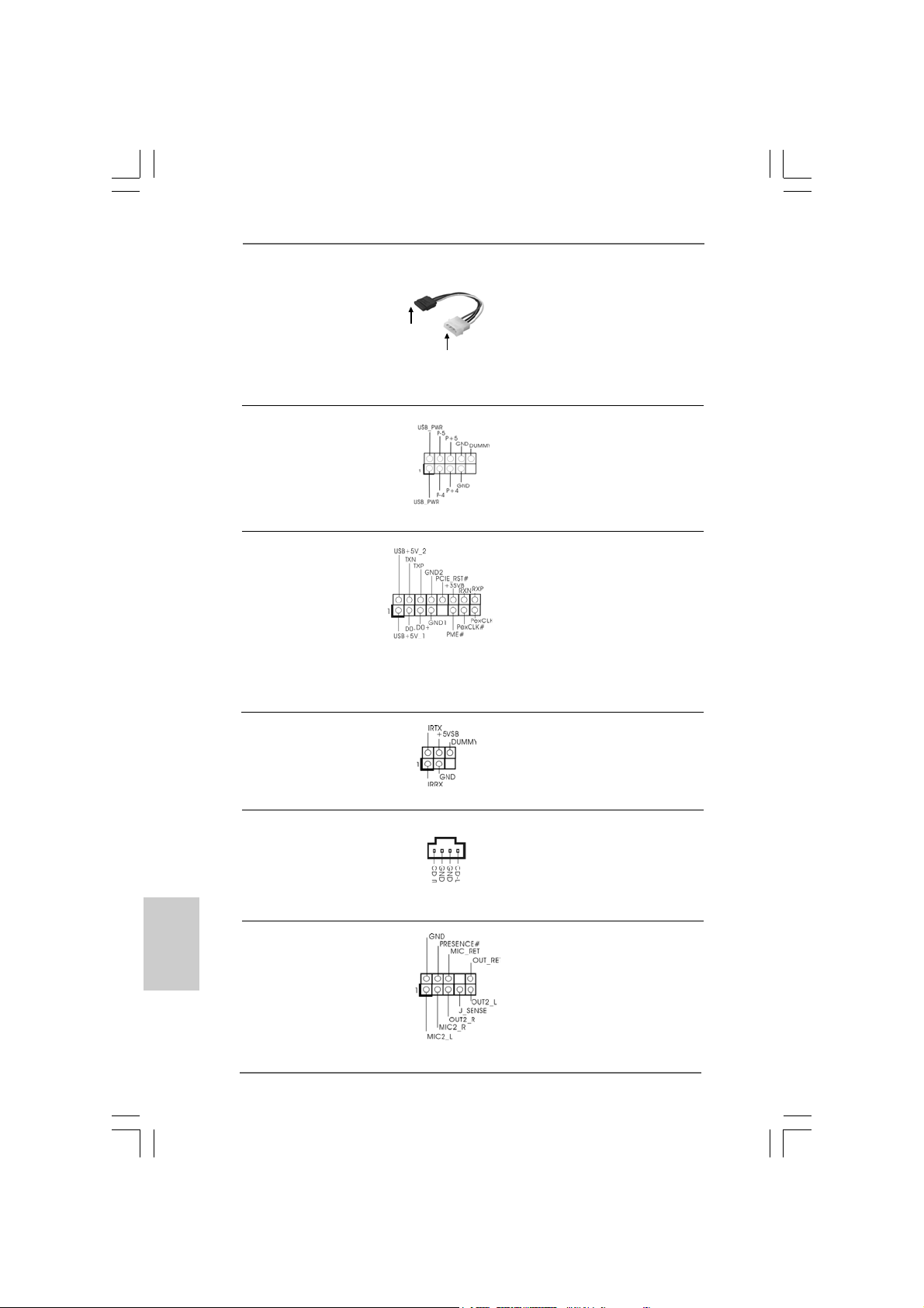
USB 2.0 Header Besides four default USB 2.0
(9-pin USB4_5) ports on the I/O panel, there is
(see p.2 No. 19) one USB 2.0 header on this
motherboard. This USB 2.0
header can support two USB
2.0 ports.
WiFi/E Header This header supports WiFi+AP
(15-pin WIFI/E) function with ASRock
(see p.2 No. 33) WiFi-802.11g or WiFi-802.11n
module, an easy-to-use wireless
local area network (WLAN)
adapter. It allows you to create a
wireless environment and enjoy the
convenience of wireless network
connectivity.
Infrared Module Header This header supports an option al
(5-pin IR1) wireless transmitting a nd
(see p.2 No. 23) receiving infrared module.
English
EnglishEnglish
EnglishEnglish
2222
22
2222
Internal Audio Connectors This connector allows you
(4-pin CD1) to receive stereo audio input
(CD1: see p.2 No. 25) from sound sources such as
CD1
a CD-ROM, D VD-ROM, TV
tuner card, or MPEG card.
Front Panel Audio Header This is a n interfa ce f or front
(9-pin HD_AUDIO1) panel audio cable that allows
(see p.2 No. 26) convenient connection and
control of audio devices.
ASRock Penryn1600SLI-110dB Motherboard
Page 23
1. High Definition Audio supports Jack Sensing, but the panel wire on
the chassis must support HDA to function correctly. Please follow the
instruction in our manual and chassis manual to install your system.
2. If you use AC’97 audio panel, please install it to the front panel audio
header as below:
A. Connect Mic_IN (MIC) to MIC2_L.
B. Connect Audio_R (RIN) to OUT2_R and Audio_L (LIN) to OUT2_L.
C. Connect Ground (GND) to Ground (GND).
D. MIC_RET and OUT_RET are for HD audio panel only. You don’t
need to connect them for AC’97 audio panel.
E. Enter BIOS Setup Utility. Enter Advanced Settings, and then select
Chipset Configuration. Set the Front Panel Control option from
[Auto] to [Enabled].
F. Enter Windows system. Click the icon on the lower right hand
taskbar to enter Realtek HD Audio Manager.
For Windows® 2000 / XP / XP 64-bit OS:
Click “Audio I/O”, select “Connector Settings” , choose
“Disable front panel jack detection”, and save the change by
clicking “OK”.
For Windows® VistaTM / VistaTM 64-bit OS:
Click the right-top “Folder” icon , choose “Disable front
panel jack detection”, and save the change by clicking “OK”.
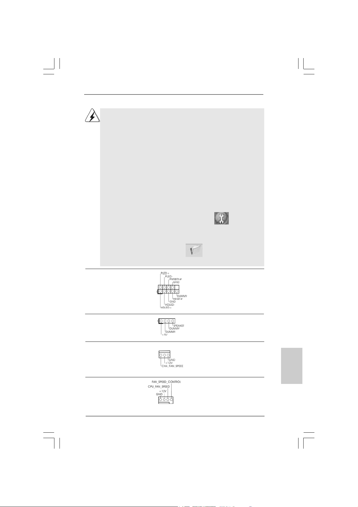
System Panel Hea der This header a ccommodate s
(9-pin PANEL1) several system front panel
(see p.2 No. 16) functions.
Chassis Spea ker He ader Please connect the chassis
(4-pin SPEAKER 1) speaker to this hea der.
(see p.2 No. 18)
Chassis Fa n Connector Please connect a chassis fan
(3-pin CHA_FAN1) cable to this connector a nd
(see p.2 No. 22) match the black wire to the
ground pin.
CPU Fan Connector Please connect a CPU fan cable
(4-pin CPU_FAN1) to this connector and match
(see p.2 No. 3) the bla ck wire to the ground pin.
1 2 3 4
ASRock Penryn1600SLI-110dB Motherboard
2323
23
2323
EnglishEnglish
EnglishEnglish
English
Page 24
Though this motherboard provides 4-Pin CPU fan (Quiet Fan) support, the 3-Pin
CPU fan still can work successfully even without the fan speed control function.
If you plan to connect the 3-Pin CPU fan to the CPU fan connector on this
motherboard, please connect it to Pin 1-3.
Pin 1-3 Connected
3-Pin Fan Installation
English
EnglishEnglish
EnglishEnglish
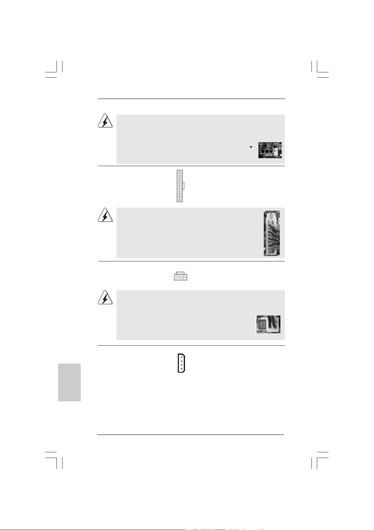
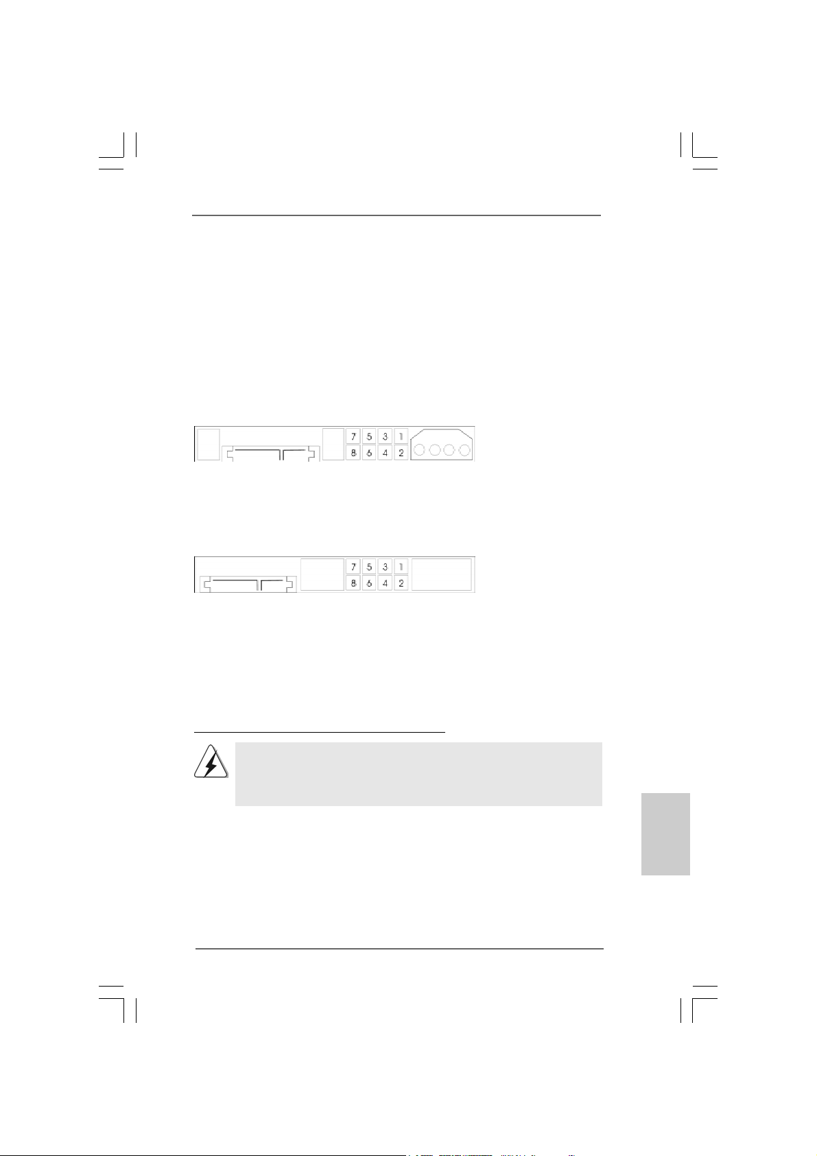
ATX Power Conne ctor Please connect an A TX power
(24-pin ATXPWR1) supply to this connector.
(see p.2, No. 2)
Though this motherboard provides 24-pin ATX power connector,
12 124
13
12
it can still work if you adopt a traditional 20-pin ATX power supply.
To use the 20-pin ATX power supply, please plug your power
supply along with Pin 1 and Pin 13.
20-Pin ATX Power Supply Installation
ATX 12V Power Connector Please connect a n A TX 12V
(8-pin ATX12V1) power supply to this connector.
(see p.2 No. 6)
5
8
1
4
1
Though this motherboard provides 8-pin ATX 12V power connector, it can still
work if you adopt a traditional 4-pin ATX 12V power supply. To use the 4-pin ATX
power supply, please plug your power supply along with Pin 1 and Pin 5.
8
4-Pin ATX 12V Power Supply Installation
4
SLI/XFIRE Power Connector It is not necessary to use this
(4-pin SLI/XFIRE_POWER1) connector, but please connect it
(see p.2 No. 34) with a hard disk power connecor
SLI/XFIRE_POWER1
when two graphics cards are
plugged to this motherboard at
the same time.
24
13
5
1
2424
24
2424
ASRock Penryn1600SLI-110dB Motherboard
Page 25
ion
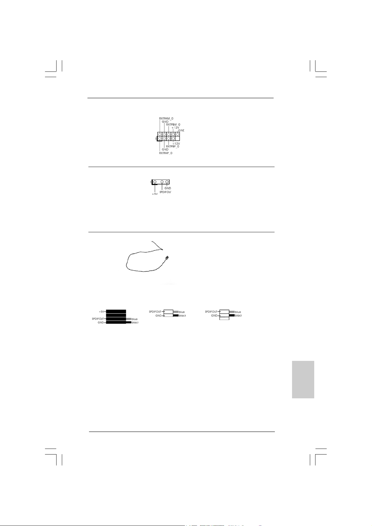
IEEE 1394 Header Besides one default IEEE 1394
(9-pin FRONT_1394) port on the I/O panel, there is one
(see p.2 No. 20) IEEE 1394 header
(FRONT_1394) on this
motherboard. This IEEE 1394
header ca n support one IEEE
1394 port.
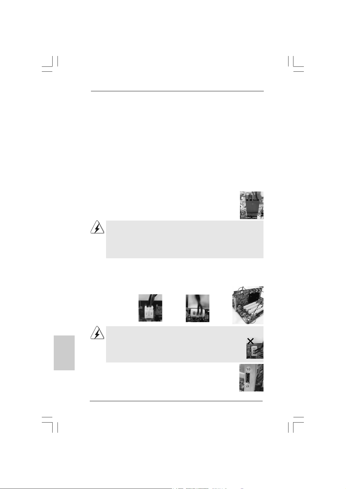
HDMI_SPDIF Header HDMI_SPDIF header, providing
(3-pin HDMI_SPDIF1) SPDIF audio output to HDMI V GA
(see p.2 No. 27) card, allows the system to
connect HDMI Digital TV/
projector/LCD devices. Ple a se
12
24
connect the HDMI_SPDIF
connector of HDMI V GA card to
this header.
HDMI_SPDIF Cable Please connect the black end (A)
1
13
(Optional) of HDMI_SPDIF cable to the
C
B
A
HDMI_SPDIF header on the
motherboard. Then connect the
white end (B or C) of
HDMI_SPDIF cable to the
HDMI_SPDIF connector of HDMI
VGA card.
A. black end B. white end (2-pin) C. white end (3-pin)
8
4
5
1
EnglishEnglish
EnglishEnglish
English
ASRock Penryn1600SLI-110dB Motherboard
2525
25
2525
Page 26
2.9 HDMI_SPDIF Header Connection Guide2.9 HDMI_SPDIF Header Connection Guide
2.9 HDMI_SPDIF Header Connection Guide
2.9 HDMI_SPDIF Header Connection Guide2.9 HDMI_SPDIF Header Connection Guide
HDMI (High-Definition Multi-media Interfa ce) is an all-digital audio/video specification,
which provides an interface between any compatible digital audio/video source,
such as a set-top box, DVD player, A/V receiver and a compatible digital audio or
video monitor, such as a digital television (DTV). A complete HDMI system requires a
HDMI VGA card and a HDMI ready motherboard with a HDMI_SPDIF header. This
motherboard is equipped with a HDMI_SPDIF header, which provides SPDIF audio
output to HDMI VGA card, allows the system to connect HDMI Digital TV/projector/
LCD devices. To use HDMI function on this motherboard, please carefully follow the
below steps.
•
Step 1. Install the HDMI VGA card to the PCI Express Graphics slot on this
motherboard. For the proper installation of HDMI VGA card, please refer
to the installation guide on page 15.
Step 2. Connect the black end (A) of HDMI_SPDIF cable to the
HDMI_SPDIF header (HDMI_SPDIF1, yellow, see page 2,
No. 27) on the motherboard.
Make sure to correctly connect the HDMI_SPDIF cable to the motherboard and the
HDMI VGA card according to the same pin definition. For the pin definition of
HDMI_SPDIF header and HDMI_SPDIF cable connectors, please refer to page 25.
For the pin definition of HDMI_SPDIF connectors on HDMI VGA card, please refer to
the user manual of HDMI VGA card vendor. Incorrect connection may cause
permanent damage to this motherboard and the HDMI VGA card.
Step 3. Connect the white end (B or C) of HDMI_SPDIF cable to the HDMI_SPDIF
connector of HDMI VGA card. (There are two white ends (2-pin and 3-pin)
on HDMI_SPDIF cable. Please choose the appropriate white end according
to the HDMI_SPDIF connector of the HDMI VGA card you install.
English
EnglishEnglish
EnglishEnglish
2626
26
2626
white end
(2-pin) (B)
Please do not connect the white end of HDMI_SPDIF cable to the wrong connector
of HDMI VGA card or other VGA card. Otherwise, the motherboard and the
VGA card may be damaged. For example, this picture shows the wrong
example of connecting HDMI_SPDIF cable to the fan connector of PCI
Express VGA card. Please refer to the VGA card user manual for
connector usage in advance.
white end
(3-pin) (C)
Step 4. Connect the HDMI output connector on HDMI VGA card to
HDMI device, such as HDTV. Please refer to the user manual
of HDTV and HDMI VGA card vendor for detailed connection
procedures.
Step 5. Install HDMI VGA card driver to your system.
ASRock Penryn1600SLI-110dB Motherboard
Page 27
2.10 SA2.10 SA
2.10 SA
2.10 SA2.10 SA
Before installing SATAII hard disk to your computer, please carefully rea d below
SATAII hard disk setup guide. Some default setting of SA TAII hard disks may not be
at SATAII mode, which operate with the best performa nce. In order to ena ble SATAII
function, please f ollow the below in struction with different vendors to correctly a djust
your SATAII hard disk to SA TAII mode in advance; otherwise, your SATAII hard disk
may fail to run at SATAII mode.
Western Digital
If pin 5 and pin 6 are shorted, SA TA 1.5Gb/s will be ena bled.
On the other hand, if you wa nt to enable SAT AII 3.0Gb/s, please remove the jumpers
from pin 5 and pin 6.
SAMSUNG
If pin 3 and pin 4 are shorted, SATA 1.5Gb/s will be enabled.
On the other hand, if you want to enable SATAII 3.0Gb/s, please remove the
jumpers from pin 3 and pin 4.
TT
AII Hard Disk Setup GuideAII Hard Disk Setup Guide
T
AII Hard Disk Setup Guide
TT
AII Hard Disk Setup GuideAII Hard Disk Setup Guide
HITACHI
Please use the Feature Tool, a DOS-bootable tool, for changing various ATA
features. Please visit HITACHI’s website for details:
http://www.hitachigst.com/hdd/support/download.htm
The above examples are just for your reference. For different SATAII hard
disk products of different vendors, the jumper pin setting methods may not
be the same. Please visit the vendors’ website for the updates.
ASRock Penryn1600SLI-110dB Motherboard
2727
27
2727
EnglishEnglish
EnglishEnglish
English
Page 28
2.112.11
Serial ASerial A
2.11
Serial A
2.112.11
Serial ASerial A
InstallationInstallation
Installation
InstallationInstallation
This motherboard adopts NVIDIA® nForce 430 chipset that supports Serial ATA (SATA)
/ Serial ATAII (SATAII) hard dis ks and RAID functions. You may install SATA / SATAII
hard disks on this motherboard for internal storage devices. This section will guide
you to install the SATA / SATAII hard dis k s.
STEP 1: Install the SATA / SATAII hard disk s into the drive bays of your chassis.
STEP 2: Connect the SATA power cable to the SAT A / SATAII hard disk.
STEP 3: Connect one end of the SATA data cable to the motherboard’s SATAII
connector.
STEP 4: Connect the other end of the SATA data cable to the SAT A / SATAII hard
disk.
2.122.12
Driver Installation GuideDriver Installation Guide
2.12
Driver Installation Guide
2.122.12
Driver Installation GuideDriver Installation Guide
To install the drivers to your system, plea se insert the support CD to your optical drive
first. Then, the drivers compatible to your system ca n be auto-detected and listed on
the support CD driver page. Please follow the order from up to bottom side to install
those required drivers. Therefore, the drivers you install can work properly.
TT
A (SAA (SA
TT
A (SA
A (SAA (SA
A) / Serial AA) / Serial A
T
A) / Serial A
TT
A) / Serial AA) / Serial A
T
TT
If you plan to use RAID 0, RAID 1 or JBOD function, you need to install at
least 2 SATA / SATAII hard disks. If you plan to use RAID 5 function, you
need to install 3 SATA / SATAII hard disks. If you plan to use RAID 0+1
function, you need to install 4 SATA / SATAII hard disks.
TT
AII (SAAII (SA
T
AII (SA
TT
AII (SAAII (SA
TT
AII) Hard DisksAII) Hard Disks
T
AII) Hard Disks
TT
AII) Hard DisksAII) Hard Disks
English
EnglishEnglish
EnglishEnglish
2828
28
2828
2.132.13
Installing WindowsInstalling Windows
2.13
Installing Windows
2.132.13
Installing WindowsInstalling Windows
TMTM
TM
/ Vista/ Vista
/ Vista
/ Vista/ Vista
If you just want to install Windows® 2000, Windows® XP , Windows® XP 64-bit, Windows
VistaTM or Windows® VistaTM 64-bit on your SATA / SATAII HDDs without RAID function s,
you don’t have to make a SA T A / SAT AII driver diskette. Besides, there is no need for you
to change the BIOS setting. You can start to install Windows® 2000, Windows® XP,
Windows® XP 64-bit, Windows® VistaTM or Windows® VistaTM 64-bit on your system
directly.
TMTM
64-bit W 64-bit W
64-bit W
64-bit W 64-bit W
ASRock Penryn1600SLI-110dB Motherboard
®
2000 / XP / XP 64-bit / Vista 2000 / XP / XP 64-bit / Vista
2000 / XP / XP 64-bit / Vista
2000 / XP / XP 64-bit / Vista 2000 / XP / XP 64-bit / Vista
ithout RAID Fithout RAID F
ithout RAID F
ithout RAID Fithout RAID F
unctionsunctions
unctions
unctionsunctions
TMTM
TM
TMTM
®
Page 29
2.142.14
Installing WindowsInstalling Windows
2.14
Installing Windows
2.142.14
Installing WindowsInstalling Windows
TMTM
TM
/ Vista/ Vista
/ Vista
/ Vista/ Vista
If you want to install Windows® 2000, Windows® XP, Windows® XP 64-bit, Windows
VistaTM or Windows® VistaTM 64-bit OS on your SATA / SATAII HDDs with RAID
functions, plea se f ollow below procedures according to the OS you install.
TMTM
64-bit W 64-bit W
64-bit W
64-bit W 64-bit W
Before installing Windows® 2000 to your system, your Windows® 2000 optical
disk is supposed to include SP4. If there is no SP4 included in your disk, please
visit the below website for proper procedures of making a SP4 disk:
http://www.microsoft.com/Windows2000/downloads/servicepacks/sp4/spdeploy.
htm#the_integrated_installation_fmay
®
2000 / XP / XP 64-bit / Vista 2000 / XP / XP 64-bit / Vista
2000 / XP / XP 64-bit / Vista
2000 / XP / XP 64-bit / Vista 2000 / XP / XP 64-bit / Vista
ith RAID Fith RAID F
ith RAID F
ith RAID Fith RAID F
unctionsunctions
unctions
unctionsunctions
TMTM
TM
TMTM
®
2.14.1 Installing Windows2.14.1 Installing Windows
2.14.1 Installing Windows
2.14.1 Installing Windows2.14.1 Installing Windows
RAID F RAID F
RAID F
RAID F RAID F
If you want to install Windows® 2000, Windows® XP or Windows® XP 64-bit on your
SATA / SATAII HDDs with RAID functions, please f ollow below steps.
STEP 1: Make a SATA / SATAII Driver Diskette.
A. Insert the ASRock Support CD into your optical drive to boot your system.
B. During POST at the beginning of system boot-up, press <F11> key, and
then a window for boot devices selection appears. Please select CD-ROM
as the boot device.
C. When you see the message on the screen, “Generate Serial ATA driver
diskette [YN]?”, press <Y>.
D. Then you will see these messages,
Please in sert a floppy dis kette into the floppy drive, and press any key.
E. The system will start to format the floppy diskette and copy SA TA / SAT AII
drivers into the floppy diskette.
STEP 2: Set Up BIOS.
A. Enter BIOS SETUP UTILITY Adva nced screen IDE Configuration.
B. Set the “SA TA Operation Mode” option to [RAID].
STEP 3: Use “RAID Installation Guide” to set RAID configuration.
Before you start to configure RAID function, you need to check the RAID installation
guide in the Support CD f or proper configuration. Please refer to the BIOS RAID
installation guide in the following path in the Support CD:
.. \ RAID Installation Guide
unctionsunctions
unctions
unctionsunctions
Please insert a blank
formatted diskette into floppy
drive A:
press any key to start
®
2000 / XP / XP 64-bit With 2000 / XP / XP 64-bit With
2000 / XP / XP 64-bit With
2000 / XP / XP 64-bit With 2000 / XP / XP 64-bit With
EnglishEnglish
EnglishEnglish
English
ASRock Penryn1600SLI-110dB Motherboard
2929
29
2929
Page 30

STEP 4: Install Windows® 2000 / Windows® XP / Windows® XP-64bit OS on your
system.
After step1, 2, 3, you can start to install Windows® 2000 / Windows® XP / Windows® XP
64-bit OS on your system. At the beginning of Windows® setup, press F6 to install a
third-party RAID driver . When prompted, insert the SATA / SAT AII driver diskette containing the NVIDIA® RAID driver. After reading the floppy disk, the driver will be presented.
Select the driver to install according to the mode you choose and the OS you install.
NOTE. If you install Windows® 2000 / Windows® XP / Windows® XP 64-bit on IDE
HDDs and want to manage (create, convert, delete, or rebuild) RAID functions
on SATA / SATAII HDDs, you still need to set up “SATA Operation Mode” to [RAID] in
BIOS first. Then, please set the RAID configuration by using the Windows RAID
installation guide in the following path in the Support CD:
.. \ RAID Installation Guide
English
EnglishEnglish
EnglishEnglish
Vista Vista
Vista
Vista Vista
TM
64-bit OS)
TM TM
TM
TM TM
/ Vista/ Vista
/ Vista
/ Vista/ Vista
2.14.2 Installing Windows2.14.2 Installing Windows
2.14.2 Installing Windows
2.14.2 Installing Windows2.14.2 Installing Windows
RAID F RAID F
RAID F
RAID F RAID F
If you want to install Windows® VistaTM or Windows® VistaTM 64-bit on your SATA /
SATAII HDDs with RAID function s, please follow below steps.
STEP 1: Set Up BIOS.
A. Enter BIOS SETUP UTILITY Adva nced screen IDE Configuration.
B. Set the “SA TA Operation Mode” option to [RAID].
STEP 2: Use “RAID Installation Guide” to set RAID configuration.
Before you start to configure RAID function, you need to check the RAID installation
guide in the Support CD f or proper configuration. Please refer to the BIOS RAID
installation guide part of the document in the following path in the Support CD:
.. \ RAID Installation Guide
STEP 3: Install Windows® VistaTM / Windows® VistaTM 64-bit OS on your
system.
Insert the Windows® VistaTM / Windows® VistaTM 64-bit optical disk into the optical drive
to boot your system, and follow the instruction to install Windows® VistaTM / Windows
VistaTM 64-bit OS on your system. When you see “Where do you want to install Windows?
” page, please in sert the ASRock Support CD into your optical drive, a nd click the “Load
Driver” button on the left on the bottom to load the NVIDIA® RAID drivers. NVIDIA® RAID
drivers are in the following path in our Support CD:
.. \ I386 \ Vista (For Windows® Vista
.. \ AMD64 \ Vista64 (For Windows® Vista
After that, please insert Windows® VistaTM / Windows® VistaTM 64-bit optical disk into
the optical drive again to continue the installation.
unctionsunctions
unctions
unctionsunctions
®
TM
OS)
TMTM
TM
TMTM
64-bit With 64-bit With
64-bit With
64-bit With 64-bit With
®
3030
30
3030
ASRock Penryn1600SLI-110dB Motherboard
Page 31

NOTE. If you install Windows® VistaTM / Windows® VistaTM 64-bit on IDE HDDs and want to
manage (create, convert, delete, or rebuild) RAID functions on SATA / SATAII HDDs,
you still need to set up “SATA Operation Mode” to [RAID] in BIOS first. Then, please
set the RAID configuration by using the Windows RAID installation guide in the
following path in the Support CD:
.. \ RAID Installation Guide
2.152.15
Untied Overclocking TUntied Overclocking T
2.15
Untied Overclocking T
2.152.15
Untied Overclocking TUntied Overclocking T
This motherboard supports Untied Overclocking Technology, which means during
overclocking, FSB enjoys better margin due to fixed PCI / PCIE buses. Before you
enable Untied Overclocking function, plea se enter “Overclock Mode” option of BIOS setup
to set the selection from [Auto] to [CPU, PCIE, Async.]. Therefore, CPU FSB is untied
during overclocking, but PCI / PCIE buses are in the fixed mode so that FSB can operate
under a more stable overclocking environment.
Please refer to the warning on page 7 for the possible overclocking risk
before you apply Untied Overclocking Technology.
echnologyechnology
echnology
echnologyechnology
ASRock Penryn1600SLI-110dB Motherboard
3131
31
3131
EnglishEnglish
EnglishEnglish
English
Page 32

3. BIOS Information3. BIOS Information
3. BIOS Information
3. BIOS Information3. BIOS Information
The Flash Memory on the motherboard stores BIOS Setup Utility. When you start up
the computer, please press <F2> during the Power-On-Self-Test (POST) to enter
BIOS Setup utility; otherwise, POST continues with its test routines. If you wish to
enter BIOS Setup after POST, please restart the system by pressing <Ctl> + <Alt> +
<Delete>, or pressing the reset button on the system chassis. The BIOS Setup
program is designed to be user-friendly. It is a menu-driven program, which allows
you to scroll through its various sub-menus and to select among the predetermined
choices. For the detailed information about BIOS Setup, please refer to the User
Manual (PDF file) contained in the Support CD.
English
EnglishEnglish
EnglishEnglish
4. Sof4. Sof
4. Sof
4. Sof4. Sof
This motherboard supports various Microsoft® Windows® operating systems: 2000 /
XP / XP 64-bit / VistaTM / Vista
contains necessary drivers and useful utilities that will enhance motherboard features.
To begin using the Support CD, insert the CD into your CD-ROM drive. It will display
the Main Menu automatically if “AUTORUN” is enabled in your computer. If the Main
Menu does not appear automatically, locate and double-click on the file “ASSETUP.
EXE” from the BIN folder in the Support CD to display the menus.
tware Supportware Suppor
tware Suppor
tware Supportware Suppor
TM
64-bit. The Support CD that came with the motherboard
t CD informationt CD information
t CD information
t CD informationt CD information
3232
32
3232
ASRock Penryn1600SLI-110dB Motherboard
Page 33

1. Einführung1. Einführung
1. Einführung
1. Einführung1. Einführung
Wir danken Ihnen für den Kauf des ASRock Penryn1600SLI-110dB Motherboard, ein
zuverlässiges Produkt, welches unter den ständigen, strengen Qualitätskontrollen von
ASRock gefertigt wurde. Es bietet Ihnen exzellente Leistung und robustes De sign, gemäß
der Verpflichtung von ASRock zu Qualität und Halbarkeit.
Diese Schnellinstallationsanle itung führt in das Motherboard und die schrittweise
Installation ein. Details über da s Motherboard finden Sie in der Bedienungsa nle itung
auf der Support-CD.
Da sich Motherboard-Spezifikationen und BIOS-Software verändern
können, kann der Inhalt dieses Handbuches ebenfalls jederzeit geändert
werden. Für den Fall, dass sich Änderungen an diesem Handbuch
ergeben, wird eine neue Version auf der ASRock-Website, ohne weitere
Ankündigung, verfügbar sein. Die neuesten Grafikkarten und unterstützten
CPUs sind auch auf der ASRock-Website aufgelistet.
ASRock-Website: http://www.asrock.com
Wenn Sie technische Unterstützung zu Ihrem Motherboard oder spezifische
Informationen zu Ihrem Modell benötigen, besuchen Sie bitte unsere
Webseite:
www.asrock.com/support/index.asp
1.1 Kartoninhalt
ASRock Penryn1600SLI-110dB Motherboard
(ATX-Formfa ktor: 30.5 cm x 22.9 cm; 12.0 Zoll x 9.0 Zoll)
Ein ASRock SLI-Brücke
ASRock Penryn1600SLI-110dB Schnellinstallationsanleitung
ASRock Penryn1600SLI-110dB Support-CD
Ein 80-adriges Ultra-A T A 66/100/133 IDE-Flachba ndka bel
Ein Flachba ndkabel für e in 3,5-Zoll-Diskettenlaufwerk
Vier Serial ATA (SATA) -Datenkabel (optional)
Ein Serial AT A (SATA) -Fe stplattenstromk abel (optional)
Ein HDMI_SPDIF-Kabel (Option)
Ein “ASRock WiFi_SPDIF I/O Plus” I/O Shield
ASRock Penryn1600SLI-110dB Motherboard
3333
33
3333
DeutschDeutsch
DeutschDeutsch
Deutsch
Page 34

Deutsch
DeutschDeutsch
DeutschDeutsch
3434
34
3434
1.21.2
SpezifikationenSpezifikationen
1.2
Spezifikationen
1.21.2
SpezifikationenSpezifikationen
Plattform - ATX-Formfaktor: 30.5 cm x 22.9 cm; 12.0 Zoll x 9.0 Zoll
- Alle Feste Kondensatordesign
CPU - LGA 775 für Intel® CoreTM 2 Extreme / CoreTM 2 Quad / Core
2 Duo / Pentium® Dual Core / Celeron® unterstützt Penryn Quad
Core Y orkfield und Dual Core Wolfdale Prozessoren
- Kompatibilität mit allen Zentraleinheiten (CPU) FSB1600/1333/
1066/800MHz (siehe VORSICHT 1)
- Unterstützt Hyper-Threading-Technologie
(siehe VORSICHT 2)
- Unterstützt Untied-Übertaktungstechnologie
(siehe VORSICHT 3)
- Unterstützt EM64T -CPU
Chipsatz - Northbridge: NVIDIA® 740i SLI / 650i SLI
- Southbridge: N VIDIA® nForce 430
Speicher - Unterstützung von Dual-Kan al-DDR2-Speichertechnologie
(siehe VORSICHT 4)
- 4 x Steckplätze für DD R2
- Unterstützt DDR2 800/667/533 non-ECC, ungepufferter
Speicher
- Max. 8GB (siehe VORSICHT 5)
Erweiterungs- - 1 x PCI Express x16-Steckplätze (Weiß)
steckplätze - 2 x PCI Express x8-Steckplätze (Gelb; nur für N VIDIA
- 1 x PCI Express x1-Steckplätze
- 3 x PCI -Steckplätze
- Unterstützt NVIDIA® SLI
Audio - 7.1 CH Windows® VistaTM Premium Niveau HD Audio mit dem
Inhalt Schutz
- DAC mit 110dB Aussteuerungsbere ich (ALC890 Audio Codec)
LAN - Gigabit LAN 10/100/1000 Mb/s
- Giga PHY Realtek RTL8211B
- Unterstützt W a ke-On-LAN
E/A-Anschlüsse ASRock WiFi_SPDIF I/O Plus
an der - 1 x PS/2-Mausanschluss
Rückseite - 1 x PS/2-Tastaturanschluss
- 1 x Serieller port: COM 1
- 1 x Paralleler port: Unterstützung für ECP / EPP
- 1 x Coaxial SPDIF Out port
- 1 x Optical SPDIF Out port
- 4 x Standard-USB 2.0-Anschlüsse
- 1 x RJ-45 Port
ASRock Penryn1600SLI-110dB Motherboard
TM
(siehe VORSICHT 6)
®
SLITM)
TM
Page 35

- 2 x RJ-45 LAN Port LED (ACT/LINK LED und
GESCHWINDIGKEIT LED)
- 1 x IEEE 1394 Port
- HD Audiobuchse: Lautspre cher seitlich / Lautspre cher hinten
/ Mitte/Bass / Audioeingang/ Lautsprecher vorne / Mikrof on
(siehe VORSICHT 7)
Anschlüsse - 4 x SATAII-Anschlüsse, unterstützt bis 3.0 Gb/s
Datenübertragungsrate, unterstützt RAID (RAID 0, RAID 1,
RAID 0+1, RAID 5 und JBOD) und NCQ Funktionen
(siehe VORSICHT 8)
- 2 x ATA133 IDE-Anschlüsse (Unterstützt bis 4 IDE-Geräte)
- 1 x F DD-Anschlüsse
- 1 x Infrarot-Modul-Header
- 1 x HDMI_SPDIF-Anschluss
- 1 x IEEE 1394-Anschluss
- CPU/Gehäuse-Lüfteranschluss
- 24-pin A TX-Netz-Header
- 8-pin anschluss für 12V -A TX-Netzte il
- SLI/XFIRE-Netz-Header
- Interne Audio-Anschlüsse
- Anschluss für Audio auf der Gehäusevorderseite
- 1 x USB 2.0-Anschlüsse (Unterstützung 2
zusätzlicher USB 2.0-Anschlüsse) (siehe VORSICHT 9)
- 1 x WiFi/E-Anschlüsse (siehe VORSICHT 10)
BIOS - 8Mb AMI BIOS
- AMI legal BIOS mit U nterstützung für “Plug and Play”
- ACPI 1.1-Weckfunktionen
- JumperFree-Modus
- SMBIOS 2.3.1
- Zentraleinheit, D RAM, NB, SB, VTT Stromspa nnung
Multianpassung
Support-CD - Treiber , Dienstprogramme, Antivirussoftware
(Probeversion)
Einzigartige - ASRock OC Tuner (siehe VORSICHT 11)
Eigenschaft - Hybrid Booster:
- Schrittloser CPU-Frequenz-Kontrolle (siehe VORSICHT 12)
- ASRock U-COP (siehe VORSICHT 13)
- Boot Failure Guard (B.F.G. – Systemstartfehlerschutz)
Hardware Monitor - Überwachung der CPU-T emperatur
- Motherboardtemperaturerkennung
- Drehza hlmessung für CPU-Lüfter
- Drehzahlmessung für Gehäuselüfter
ASRock Penryn1600SLI-110dB Motherboard
3535
35
3535
DeutschDeutsch
DeutschDeutsch
Deutsch
Page 36

Deutsch
DeutschDeutsch
DeutschDeutsch
3636
36
3636
- CPU-Lüftergeräuschdämpfung
- Spannungsüberwa chung: +12V, +5V, +3.3V, Vcore
Betriebssysteme - Unterstützt Microsoft® Windows® 2000 / XP / XP 64-Bit /
VistaTM / Vista
TM
64-Bit
Zertifizierungen - FCC, CE, WHQL
* Für die ausführliche Produktinformation, besuchen Sie bitte unsere Website:
http://www.asrock.com
WARNUNG
Beachten Sie bitte, dass Overclocking, einschließlich der Einstellung im BIOS, Anwenden
der Untied Overclocking-Technologie oder V erwenden von Overclocking-Werkzeugen von
Dritten, mit einem gewissen Risiko behaftet ist. Overclocking kann sich nachteilig auf die
Stabilität Ihres Systems auswirken oder sogar Komponenten und Geräte Ihres Systems
beschädigen. Es geschieht dann auf eigene Gefahr und auf Ihre Kosten. Wir übernehmen
keine Verantwortung für mögliche Schäden, die aufgrund von Overclocking verursacht
wurden.
VORSICHT!
1. FSB1600-CPU funktioniert in Übertakten Modus.
2. Die Einstellung der “Hyper-Threading Technology”, finden Sie auf
Seite 40 des auf der Support-CD enthaltenen Benutzerhandbuches
beschrieben.
3. Dieses Motherboard unterstützt die Untied-Übertaktungstechnologie.
Unter “Entkoppelte Übertaktungstechnologie” auf Seite 61 finden Sie
detaillierte Informationen.
4. Dieses Motherboard unterstützt Dual-Kanal-Speichertechnologie. Vor
Implementierung der Dual-Kanal-Speichertechnologie müssen Sie die
Installationsanleitung für die Speichermodule auf Seite 43 zwecks
richtigerInstallation gelesen haben.
5. Durch Betriebssystem-Einschränkungen kann die tatsächliche
Speichergröße weniger als 4 GB betragen, da unter Windows® XP und
Windows® Vista™ etwas Speicher zur Nutzung durch das System
reserviert wird. Unter Windows® XP 64-bit und Windows® Vista™ 64-bit
mit 64-Bit-CPU besteht diese Einschränkung nicht.
6. Dieses Motherboard unterstützt die NVIDIA® SLITM-Technologie. Die
PCIE2- und PCIE4-Steckplätze (gelb) sind für die SLITM-Funktion
vorgesehen. Sofern Sie nur eine PCI Express-VGA-Karte in diesem
Motherboard einsetzen möchten, installieren Sie diese bitte im PCIE3Steckplatz. Informationen zu SLITM-Modus-kompatiblen PCI ExpressVGA-Karten finden Sie unter „Unterstützte PCI Express-VGA-Karten für
den SLITM-Modus“ auf Seite 9. Hinweise zur richtigen Installation von PCI
Express-VGA-Karten finden Sie in der Installationsanleitung auf Seite 45.
7. Der Mikrofoneingang dieses Motherboards unterstützt Stereo- und
Mono-Modi. Der Audioausgang dieses Motherboards unterstützt 2Kanal-, 4-Kanal-, 6-Kanal- und 8-Kanal-Modi. Stellen Sie die richtige
Verbindung anhand der Tabelle auf Seite 3 her.
ASRock Penryn1600SLI-110dB Motherboard
Page 37

8. Bevor Sie eine SATA II Festplatte mit dem SATA II Anschluss verbinden,
lesen Sie bitte die “Anleitung zur SATA II Festplatteneinrichtung“ auf
Seite 59, um Ihre SATA II Festplatte in den SATA II Modus
umzuschalten. SATA-Festplatten können Sie auch direkt mit dem SATA
II-Anschluss verbinden.
9. Das Power Management für USB 2.0 arbeitet unter Microsoft
Windows® VistaTM 64-Bit / VistaTM / XP 64-Bit / XP SP1 oder SP2/2000
SP4 einwandfrei.
10. WiFi/E Sockel unterstützt WiFi+AP Funktion mit ASRock WiFi-802.11g
oder WiFi-802.11n Modul, einem einfach zu bedienenden Wireless
Local Area Network (WLAN) Adapter. Damit sind Sie in der Lage, ein
drahtloses Netzwerk aufzubauen und die Vorzüge drahtloser
Anschlussmöglichkeiten zu genießen. Für Verfügbarkeit des ASRock
WiFi-802.11g oder WiFi-802.11n Moduls, siehe bitte unsere
Webseite. ASRock Webseite http://www.asrock.com
11. Es ist ein benutzerfreundlicher ASRock Übertaktenswerkzeug, das
erlaubt, dass Sie Ihr System durch den Hardware-Monitor Funktion zu
überblicken und Ihre Hardware-Geräte übertakten, um die beste
Systemleistung unter der Windows® Umgebung zu erreichen.
Besuchen Sie bitte unsere Website für die Operationsverfahren von
ASRock OC Tuner. ASRock-Website: http://www.asrock.com
12. Obwohl dieses Motherboard stufenlose Steuerung bietet, wird
Overclocking nicht empfohlen. Frequenzen, die über den für den
jeweiligen Prozessor vorgesehenen liegen, können das System
instabil werden lassen oder die CPU beschädigen.
13. Wird eine Überhitzung der CPU registriert, führt das System einen
automatischen Shutdown durch. Bevor Sie das System neu starten,
prüfen Sie bitte, ob der CPU-Lüfter am Motherboard richtig funktioniert,
und stecken Sie bitte den Stromkabelstecker aus und dann wieder ein.
Um die Wärmeableitung zu verbessern, bitte nicht vergessen, etwas
Wärmeleitpaste zwischen CPU und Kühlkörper zu sprühen.
®
ASRock Penryn1600SLI-110dB Motherboard
3737
37
3737
DeutschDeutsch
DeutschDeutsch
Deutsch
Page 38

1.31.3
Minimale Hardwarevorausetzungen für WindowsMinimale Hardwarevorausetzungen für Windows
1.3
Minimale Hardwarevorausetzungen für Windows
1.31.3
Minimale Hardwarevorausetzungen für WindowsMinimale Hardwarevorausetzungen für Windows
TMTM
TM
TMTM
VistaVista
Vista
VistaVista
Systemintegratoren und Anwender unseres Motherboards, die ihre
Rechner auf die Verga be de s Windows® VistaTM Premium 2008 und Ba sic Logos vorbereiten möchten, finden die minimalen
hardwarevoraussetzungen in der folgenden Tabelle.
CPU Celeron 420
Speicher 1 GB Systemspeicher (Premium)
V GA DX10.0 mit WDDM-Treiber
* Nach dem ersten Juni, 2008 sind , all Windows® VistaTM Systems dafür
erforderlich, mit der Minimalforderung der obengenannte Hardware
übereinzustimmen, um Windows® VistaTM Premium 2008 logo.zu befähigen.
Premium 2008 und Basic Logo Premium 2008 und Basic Logo
Premium 2008 und Basic Logo
Premium 2008 und Basic Logo Premium 2008 und Basic Logo
512 MB, Single Channel (Basic)
mit 128 Bit-VGA-Speicher (Pre mium)
mit 64 Bit-VGA-Speicher (Basic)
®
Deutsch
DeutschDeutsch
DeutschDeutsch
3838
38
3838
ASRock Penryn1600SLI-110dB Motherboard
Page 39

2. Installation2. Installation
2. Installation
2. Installation2. Installation
Sicherheitshinweise vor der MontageSicherheitshinweise vor der Montage
Sicherheitshinweise vor der Montage
Sicherheitshinweise vor der MontageSicherheitshinweise vor der Montage
Bitte nehmen Sie die folgende Sicherheitshinweise zur Kenntnis, bevor Sie das
Motherboard einbauen oder Veränderungen an den Einstellungen vornehmen.
1. Trennen Sie das System vom Stromnetz, bevor Sie eine ystemkomponente
berühren, da es sonst zu schweren Schäden a m Motherboard oder den
sonstigen internen, bzw. externen omponenten kommen kann.
2. Um Schäden aufgrund von statischer Elektrizität zu vermeiden, das
Motherboard NIEMALS auf einen Teppich o.ä.legen. Denken Sie außerem
daran, immer ein geerdetes Armband zu tragen oder ein geerdetes Objekt
aus Metall zu berühren, bevor Sie mit Systemkomponenten hantieren.
3. Halten Sie Komponenten immer an den Rändern und vermeiden Sie
Berührungen mit den ICs.
4. Wenn Sie Komponenten ausbauen, legen Sie sie immer auf eine
antistatische Unterlage, oder zurück in die Tüte, mit der die Komponente
geliefert wurde.
5. Wenn Sie das Motherboard mit den Schrauben an dem Computergehäuse
befestigen, überziehen Sie bitte die Schrauben nicht! Das Motherboard kann
sonst beschädigt werden.
2.1 CPU Installation2.1 CPU Installation
2.1 CPU Installation
2.1 CPU Installation2.1 CPU Installation
Für die Installation des Intel 775-Pin CPU
führen Sie bitte die folgenden Schritte durch.
(Ladeplatte)
(Kontaktreihe)
(Sockel)
775-Pin Sockel Übersicht
Bevor Sie die 775-Pin CPU in den Sockel sitzen, prüfen Sie bitte,
ob die CPU-Oberfläche sauber ist und keine der Kontakte verbogen
sind. Setzen Sie die CPU nicht mit Gewalt in den Sockel, dies kann
die CPU schwer beschädigen.
ASRock Penryn1600SLI-110dB Motherboard
3939
39
3939
DeutschDeutsch
DeutschDeutsch
Deutsch
Page 40

Schritt 1. Öffnen Sie den Sockel:
Schritt 1-1. Öffnen Sie den Hebel, indem
Sie ihn nach unten drücken und
aushaken.
Schritt 1-2. Drehen Sie den Ladehebel, bis
er in geöffneter Position steht,
ca. 135 Grad.
Schritt 1-3. Drehen Sie die Ladeplatte, bis
sie in geöffneter Position steht,
ca. 100 Grad.
Schritt 2. 775-Pin CPU einstecken:
Schritt 2-1. Halten Sie die CPU an den mit
schwarzen Linien
gekennzeichneten Seiten.
Schritt 2-2. Halten Sie das Teil mit dem IHS
(Integrated Heat Sink –
integrierter Kühlkörper) nach
oben. Suchen Sie Pin 1 und die
zwei
Orientierungseinkerbungen.
Pin1
Orientierungskerbe
Ausrichtungsmarkierung
Orientierungskerbe
Pin1
Schwarze Linie
775-Pin Sockel
Schwarze Linie
Ausrichtungsmarkierung
Deutsch
DeutschDeutsch
DeutschDeutsch
4040
40
4040
775-Pin CPU
Um die CPU ordnungsgemäß einsetzen zu können, richten Sie die
zwei Orientierungskerben der CPU mit den beiden Markierungen des
Sockels aus.
Schritt 2-3. Drücken Sie die CPU vorsichtig
in vertikaler Richtung in den
Sockel.
ASRock Penryn1600SLI-110dB Motherboard
Page 41

Schritt 2-4. Prüfen Sie, dass die CPU
ordnungsgemäß im Sockel sitzt
und die Orientierungskerben
einwandfrei in den
entsprechenden Auskerbungen
sitzen.
Schritt 3. PnP-Kappe entfernen (Pick and Place-Kappe):
Halten Sie den Rand der Ladeplatte mit
Zeigefinger und Daumen Ihrer linken Hand,
halten Sie die PnP-Kappe mit dem Daumen
der rechten Hand und ziehen Sie die Kappe
vom Sockel während Sie auf die Mitte der
Kappe drücken, um ein Entfernen zu
erleichtern.
1. Verwenden Sie beim Entfernen die Kappenlasche und vermeiden
Sie ein Abreißen der PnP-Kappe.
2. Diese Kappe muss angebracht werden, falls Sie das Motherboard
zur Reparatur bringen.
Schritt 4. Sockel schließen:
Schritt 4-1. Drehen Sie die Ladeplatte auf
den Kühlkörper (IHS).
Schritt 4-2. Drücken Sie leicht auf die
Ladeplatte und schließen Sie
den Ladehebel.
Schritt 4-3. Sichern Sie Ladehebel und
Ladeplatte mithilfe des
Hebelverschlusses.
ASRock Penryn1600SLI-110dB Motherboard
4141
41
4141
DeutschDeutsch
DeutschDeutsch
Deutsch
Page 42

2.22.2
Installation des CPU-Lüfters und KühlkörpersInstallation des CPU-Lüfters und Kühlkörpers
2.2
Installation des CPU-Lüfters und Kühlkörpers
2.22.2
Installation des CPU-Lüfters und KühlkörpersInstallation des CPU-Lüfters und Kühlkörpers
Für Installationshinweise, siehe Betriebsanleitung Ihres CPU-Lüfters und
Kühlkörpers.
Unten stehend ein Beispiel zur Installation eines Kühlkörpers für den 775-Pin CPU.
Schritt 1. Geben Sie Wärmeleitmaterial auf die Mitte
des IHS, auf die Sockeloberfläche.
Schritt 2. Setzen Sie den Kühlkörper auf den Sockel.
Prüfen Sie, dass die Lüfterkabel auf der
Seite am nächsten zum CPU-LüfterAnschluss des Motherboards verlaufen
(CPU_FAN1, siehe Seite 2, Nr. 3).
Schritt 3. Richten Sie Verbindungselemente und
Löcher im Motherboard aus.
Schritt 4. Drehen Sie die Verbindungselemente im
Uhrzeigersinn und drücken Sie mit dem
Daumen auf die Kappen der Elemente zum
Feststellen. Wiederholen Sie dies mit den
anderen Verbindungselementen.
Wenn Sie die Verbindungselemente nur drücken, ohne sie im
Uhrzeigersinn zu drehen, wird der Kühlkörper nicht ordnungsgemäß
am Motherboard befestigt.
(Tragen Sie Wärmeleitmaterial auf. )
(Lüfterkabel auf der Seite am nächsten
zum Anschluss des Motherboards)
(Schlitze der Verbindungselemente
nach außen)
(Nach unten drücken (4 Stellen))
Deutsch
DeutschDeutsch
DeutschDeutsch
4242
42
4242
Schritt 5. Schließen Sie den Lüfter an den CPU-
Lüfteranschluss des Motherboards.
Schritt 6. Befestigen Sie überschüssiges Kabel mit
Band, um eine Störung des Lüfters oder
Kontakt mit anderen Teilen zu vermeiden.
ASRock Penryn1600SLI-110dB Motherboard
Page 43

2.3 Installation der Speichermodule (DIMM)2.3 Installation der Speichermodule (DIMM)
2.3 Installation der Speichermodule (DIMM)
2.3 Installation der Speichermodule (DIMM)2.3 Installation der Speichermodule (DIMM)
Die Motherboards Penryn1600SLI-110dB bieten vier 240-pol. DDR2 (Double Data Rate
2) DIMM-Steck plätze und unterstützen die Dual-Ka nal-Speicherte chnologie. Für die
Dual-Kanalkonfiguration dürfen Sie nur identische (gleiche Marke, Ge schwindigkeit,
Größe und gleicher Chiptyp) DDR2 DIMM-Paare in den Steckplätzen gleicher Farbe
installieren. Mit anderen W orten, sie müssen e in identisches DDR2 DIMM-Paar i m
Dual-Kanal A (DDRII_1 und DDRII_3; gelbe Steckplätze, siehe Seite 2 Nr. 7) oder ein
identisches DDR2 DIMM-Paar im Dual-Kanal B (DDRII_2 und DDRII_4; orange
Steckplätze, siehe Seite 2 Nr. 8) installieren, da mit die Dual-KanalSpeichertechnologie aktiviert werden ka nn. Auf die sem Motherboard können Sie auch
vier DDR2 DIMMs für eine Dual-Kan alkonfiguration installieren. Auf diesem
Motherboard können Sie auch vier DDR2 DIMM-Module für eine DualKanalkonfiguration installieren, wobe i Sie bitte in allen vier Steckplätzen identische
DDR2 DIMM-Module in stallieren. Beziehen Sie sich dabei auf die n a chstehende
Konfigurationstabelle für Dual-Kan alspeicher.
Dual-Kanal-Speicherkonfigurationen
DDRII_1 DDRII_2 DDRII_3 DDRII_4
(gelbe) (orange) (gelbe) (orange)
(1) Bestückt - Bestückt (2) - Bestückt - Bestückt
(3) Bestückt Bestückt Bestückt Bestückt
* Für Konfiguration (3) installieren Sie bitte identische DDR2 DIMMs in allen vier
• Steckplätzen.
1. Wenn Sie zwei Speichermodule installieren möchten, verwenden
Sie dazu für optimale Kompatibilität und Stabilität Steckplätze
gleicher Farbe. Installieren Sie die beiden Speichermodule also
entweder in den gelbe Steckplätzen (DDRII_1 und DDRII_3) oder
den orange Steckplätzen (DDRII_2 und DDRII_4).
2. Wenn nur ein Speichermodul oder drei Speichermodule in den
DDR2 DIMM-Steckplätzen auf diesem Motherboard installiert sind,
kann es die Dual-Kanal-Speichertechnologie nicht aktivieren.
3. Ist ein Speichermodulpaar NICHT im gleichen “Dual-Kanal”
installiert, z.B. ein Speichermodulpaar wird in DDRII_1 und
DDRII_2 installiert, kann es die Dual-Kanal-Speichertechnologie
nicht aktivieren.
4. Es ist nicht zulässig, DDR in einen DDR2 Steckplatz zu
installieren; andernfalls könnten Motherboard und DIMMs
beschädigt werden.
ASRock Penryn1600SLI-110dB Motherboard
4343
43
4343
DeutschDeutsch
DeutschDeutsch
Deutsch
Page 44

Einsetzen eines DIMM-ModulsEinsetzen eines DIMM-Moduls
Einsetzen eines DIMM-Moduls
Einsetzen eines DIMM-ModulsEinsetzen eines DIMM-Moduls
Achten Sie darauf, das Netzteil abzustecken, bevor Sie DIMMs oder
Systemkomponenten hinzufügen oder entfernen.
Schritt 1: Öffnen Sie einen DIMM-Slot, indem Sie die seitlichen Clips nac h außen
drücken.
Schritt 2: Richten Sie das DIMM-Modul so über dem Slot aus, dass das Modul mit
der Kerbe in den Slot passt.
Die DIMM-Module passen nur richtig herum eingelegt in die
Steckplätze. Falls Sie versuchen, die DIMM-Module mit Gewalt falsch
herum in die Steckplätze zu zwingen, führt dies zu dauerhaften
Schäden am Mainboard und am DIMM-Modul.
Deutsch
DeutschDeutsch
DeutschDeutsch
4444
44
4444
Schritt 3: Drücken Sie die DIMM-Module fest in die Steckplätze, so da ss die
Halteklammern an beiden Enden des Moduls einschnappen und das
DIMM-Modul fest an Ort und Stelle sitzt.
ASRock Penryn1600SLI-110dB Motherboard
Page 45

2.42.4
Erweiterungssteckplätze (PCI-Steckplätze und PCIErweiterungssteckplätze (PCI-Steckplätze und PCI
2.4
Erweiterungssteckplätze (PCI-Steckplätze und PCI
2.42.4
Erweiterungssteckplätze (PCI-Steckplätze und PCIErweiterungssteckplätze (PCI-Steckplätze und PCI
ExpressExpress
Express
ExpressExpress
Es gibt einen 3 PCI-Steckplätze und 4 PCI Express-Steckplätze am
Penryn1600SLI-110dB Motherboard.
PCI-Slots: PCI-Slots werden zur Installation von Erweiterungskarten mit dem
PCI Express-Slots: PCIE1 (PCIE x1-Steckplatz) wird für PCI Express-
-Steckplätze)-Steckplätze)
-Steckplätze)
-Steckplätze)-Steckplätze)
32bit PCI-Interface genutzt.
Grafikkarten mit x1-Busbreite verwendet wie Gigabit LANKarten, SATA2-Karten, usw. einge setzt.
PCIE2 / PCIE4 (PCIE x8-Steckplatz) werden zur Installation
von PCI Express-Erweiterungskarten zur U nterstützung der
SLITM-Funktionalität genutzt. Informationen zu SLITM-Moduskompatiblen PCI Express-VGA-Karten f inden Sie unter
„Unterstützte PCI Express-V GA-Karten für den SLI™Modus“ auf Seite 9.
PCIE3 (PCIE x16-Steckplatz) wird für PCI ExpressGrafikkarten mit x16-Busbreite verwendet.
1. Dieses Motherboard unterstützt die NVIDIA® SLITM-Technologie. Die PCIE2-
und PCIE4-Steckplätze (gelb) sind ausschließlich für die SLITM Funktionalität vorgesehen. Wir raten von der Installation anderer
Grafikkarten in den PCIE2- und PCIE4-Steckplätzen ab und übernehmen
keine Funktionsgarantien einer solchen Konfiguration.
2. Bei diesem Motherboard können Sie sich lediglich zwischen PCIE3- oder
PCIE2/PCIE4-Steckplatz entscheiden. Sofern Sie nur eine PCI Express VGA-Karte in diesem Motherboard einsetzen möchten, installieren Sie
diese bitte im PCIE3-Steckplatz.
Einbau einer ErweiterungskarteEinbau einer Erweiterungskarte
Einbau einer Erweiterungskarte
Einbau einer ErweiterungskarteEinbau einer Erweiterungskarte
Schritt 1: Bevor Sie die Erweiterungskarte installieren, vergewissern Sie sich,
dass das Netzteil ausge schaltet und das Netzka bel a bgezogen ist.
Bitte lesen Sie die Dokumentation zur Erweiterungsk arte und nehmen
Sie nötige Hardware-Einstellungen für die Karte vor, ehe Sie mit der
Installation beginnen.
Schritt 2: Entfernen Sie da s Abde ckungsblech (Slotblende) von dem
Gehäuseschacht (Slot) , den Sie nutzen möchten und behalten die
Schraube für den Einbau der Karte.
Schritt 3: Richten Sie die Karte über dem Slot aus und drücken Sie sie ohne
Gewalt hinein, bis sie den Steckplatz korrekt ausfüllt.
Schritt 4: Befestigen Sie die Karte mit der Schraube aus Schritt 2.
ASRock Penryn1600SLI-110dB Motherboard
4545
45
4545
DeutschDeutsch
DeutschDeutsch
Deutsch
Page 46

TMTM
TM
2.52.5
2.5
2.52.5
Dieses Motherboard unterstützt NVIDIA® SLITM (Scalable Link Interface) Technologie,
die es Ihnen ermöglicht, zwei identische PCI Express x16-Grafikkarten mit NVIDIA
SLITM zu installieren. Derzeit unterstützt die NVIDIA SLITM-Technologie das Windows
XP, XP 64-Bit, VistaTM und VistaTM 64-Bit Betriebssystem. Bitte befolgen Sie die
Installationsanleitung in diese m Abschnitt.
Genießen Sie die VGenießen Sie die V
Genießen Sie die V
Genießen Sie die VGenießen Sie die V
Schritt 1. Installieren Sie die identischen, SLITM-tauglichen und N VIDIA®-
TMTM
SLISLI
Bedienungsanleitung Bedienungsanleitung
SLI
Bedienungsanleitung
SLISLI
Bedienungsanleitung Bedienungsanleitung
SLITM-Technologie - Voraussetzungen
1. Sie sollten bereits über zwei SLITM-taugliche Grafikkarten verfügen, die
NVIDIA®-zertifiziert sind.
2. Vergewissern Sie sich, dass Ihr Grafikkartentreiber die NVIDIA
Technologie unterstützt. Laden Sie den aktuellsten Treiber von der
NVIDIA
3. Vergewissern Sie sich, dass Ihr Netzteil zumindest die
Minimalanforderungen Ihres Systems erfüllt.
zertifizierten Grafikk arten, da verschiedene T ypen von Grafikkarten
nicht ordnungsgemäß zusammen arbeiten. (Selbst wenn die GPUChipversion dieselbe ist.) Installieren Sie eine Grafikkarte in
Steckplatz PCIE2 und die andere Grafikkarte in Steckplatz PCIE4.
Vergewissern Sie sich, dass die Karten ordnungsgemäß in die
Steckplätze eingera stet sind.
®
-Website (www.nvidia.com) herunter.
TMTM
TM
oror
züge von SLIzüge von SLI
or
züge von SLI
oror
züge von SLIzüge von SLI
TMTM
®
SLITM-
®
®
Deutsch
DeutschDeutsch
DeutschDeutsch
4646
46
4646
Schritt 2. Schließen Sie im Bedarfsfall eine zusätzliche Stromversorgung an die
PCI Express-Grafikkarten an.
Schritt 3. Richten Sie die SLI-Brücke mit den Goldkonta kten a n jeder Grafikkarte
aus und schieben Sie die Brücke darauf. Vergewissern Sie sich,
dass die SLI-Brücke ordnungsgemäß einrastet.
ASRock Penryn1600SLI-110dB Motherboard
Page 47

Schritt 4. Schließen Sie ein VGA-Kabel oder DVI-I-Kabel an den
Monitoranschluss und a n den DVI-An schluss der in Steck platz
PCIE2 installierten Grafikk arte a n.
Schritt 5. Schließen Sie ein 4-poliges A TX-V ersorgungsk abel a n den SLI/
XFIRE-Versorgungsa nschluss an.
Schritt 6. Installieren Sie die Grafikkartentreiber auf Ihre m System. Da nach
können Sie die Multi-Graphics Proce ssing U nit- (GPU-) Funktion mit
dem NVIDIA® nView-Dienstprogra mm in der Systemablage
aktivieren. Bitte gehen Sie wie na chstehend beschrieben vor, um
die Multi-GPU-Funktion zu aktivieren.
Für Windows® XP / XP 64-Bit Betriebssystem:
A. Klicken Sie auf das Symbol NVIDIA Settings icon(NVIDIA Einstellungen) in der Systemablage von Windows®.
B. Wählen Sie aus dem Kontextmenü nView Desktop Manager
und klicken Sie anschließend auf nView Properties (nView-
Eigenschaften).
C. Wählen Sie aus dem Fenster “nView Desktop Manager” die
Registerkarte Desktop Management.
D. Klicken Sie auf Properties (Eigenschaften), um das Dialogfeld
der Anzeigee igenschaften zu öf fnen.
ASRock Penryn1600SLI-110dB Motherboard
4747
47
4747
DeutschDeutsch
DeutschDeutsch
Deutsch
Page 48

Deutsch
DeutschDeutsch
DeutschDeutsch
E. Wählen Sie aus dem Dialogfeld der Anzeigeeigenschaften die
Registerkarte Settings (Einstellungen)und klicken Sie auf
Advanced (Erweitert).
F. Wählen Sie die Registerkarte N VIDIA GeForce.
4848
48
4848
G. Klicken Sie auf den Schieberegler, um den folgenden Bildschirm
anzuzeigen und wählen Sie a n schließend das Element SLI Multi-
GPU aus.
ASRock Penryn1600SLI-110dB Motherboard
Page 49

H. Aktivieren Sie das Kontrollkästchen Enable SLI Multi-GPU (SLI
Multi-GPU aktivieren).
I. Klicken Sie anschließend auf OK.
Für Windows® VistaTM / VistaTM 64-Bit Betriebssystem:
A. Klicken Sie in der Windows®-Taskleiste auf Start .
B. Wählen Sie Alle Programme aus dem Menü, klicken Sie dann
auf NVIDIA Corporation.
C. Wählen Sie das Register NVIDIA-Bedienfeld.
D. Wählen Sie das Register Bedienfeld.
ASRock Penryn1600SLI-110dB Motherboard
4949
49
4949
DeutschDeutsch
DeutschDeutsch
Deutsch
Page 50

E. Wählen Sie SLI-Konfiguration festlegen aus dem Popup-Menü,
klicken Sie dann auf Anwenden.
* SLITM ist eine eingetragene Marke von NVIDIA® Technologies Inc. und wird ohne die
Absicht einer Markenrechtsverletzung lediglich zum Zwecke der Identifikation und
Erklärung für den Benutzer verwendet.
Deutsch
DeutschDeutsch
DeutschDeutsch
5050
50
5050
ASRock Penryn1600SLI-110dB Motherboard
Page 51

2.6 “Surround Display”2.6 “Surround Display”
2.6 “Surround Display”
2.6 “Surround Display”2.6 “Surround Display”
Dieses Motherboard unterstützt Surround Display-Aufrüstung. M it zusätzlichen PCI
Express-VGA-Karte können Sie die V orteile der Surround Display-Funktion problemlos
genießen. Für detaillierte Informationen, siehe folgendes Dokument auf beiliegender
Support-CD: ..\ Surround Display Information
2.7 Einstellung der Jumper2.7 Einstellung der Jumper
2.7 Einstellung der Jumper
2.7 Einstellung der Jumper2.7 Einstellung der Jumper
Die Abbildung verdeutlicht, wie Jumper
gesetzt werden. Werden Pins durch
Jumperkappen verdeckt, ist der Jumper
“Gebrückt”. Werden keine Pins durch
Jumperkappen verdeckt, ist der Jumper
“Offen”. Die Abbildung zeigt einen 3-Pin
Jumper dessen Pin1 und Pin2 “Gebrückt”
sind, bzw. es befindet sich eine JumperKappe auf diesen beiden Pins.
Jumper Einstellun Beschreibung
PS2_USB_PWR1 Überbrücken Sie Pin2, Pin3, um
(siehe S.2 - No. 1) +5VSB (Standby) zu setzen
Hinweis: Um +5VSB nutzen zu können, muss das Netzteil auf dieser Leitung 2A
oder mehr leisten können.
Gebrückt Offen
und die PS/2 oder USBWe ckfunktionen zu aktivieren.
CMOS löschen
(CLRCMOS1, 3-Pin jumper)
(siehe S.2 - Nr. 17)
Hinweis: CLRCMOS1 erlaubt Ihnen das Löschen der CMOS-Daten. Diese beinhalten
das System-Passwort, Datum, Zeit und die verschiedenen BIOS-Parameter.
Um die Systemparameter zu löschen und auf die Werkseinstellung
zurückzusetzen, schalten Sie bitte den Computer ab und entfernen da s
Stromkabel. Benutzen Sie eine Jumperkappe, um die Pin 2 und Pin 3 an
CLRCMOS1 für 5 Sekunden kurzzuschließen. Bitte vergessen Sie nicht,
den Jumper wieder zu entfernen, nachdem das CMOS gelöscht wurde. Bitte
vergessen Sie nicht, den Jumper wieder zu entfernen, nachde m da s CMOS
gelöscht wurde. W enn Sie den CMOS-Inhalt gleich n a ch de m Aktualisieren
des BIOS löschen müssen, müssen Sie zuerst da s System starten und
dann wieder ausschalten, bevor Sie den CMOS-Inhalt löschen.
ASRock Penryn1600SLI-110dB Motherboard
DefaultEinstellung
CMOS
löschen
5151
51
5151
DeutschDeutsch
DeutschDeutsch
Deutsch
Page 52

2.8 Anschlüsse2.8 Anschlüsse
2.8 Anschlüsse
2.8 Anschlüsse2.8 Anschlüsse
Anschlussleisten sind KEINE Jumper. Setzen Sie KEINE Jumperkappen
auf die Pins der Anschlussleisten. Wenn Sie die Jumperkappen auf die
Anschlüsse setzen, wird das Motherboard permanent beschädigt!
Anschluss Beschreibung
Anschluss für das
Floppy-Laufwerk
(33-Pin FLOPPY1)
(siehe S.2, Nr. 24)
die rotgestreifte Seite auf Stift 1
Hinweis: Achten Sie darauf, dass die rotgestreifte Seite des Ka bel mit der Stift 1-
Seite des An schlusses verbunden wird.
Primärer IDE-Anschluss (blau) Sekundärer IDE-Anschlus (schwarz)
(39-pin IDE1, siehe S.2 - Nr. 10) (39-pin IDE2, siehe S.2 - Nr. 9)
Blauer Anschluss Schwarzer Anschluss
zum Motherboard zur Festplatte
80-adriges ATA 66/100/133 Kabel
Hinweis: Wenn Sie auf die sem Motherboard nur ein IDE-Gerät einsetzen, richten
Sie das IDE-Gerät als “M aster” ein. Details entnehmen Sie bitte den
Anweisungen Ihres IDE-Gerätehändlers. Zur Optimierung der Kompatibilität
und Leistung verbinden Sie die Festplatte mit dem primären IDE-Anschluss
(IDE1, blau) und das CD-ROM mit de m sekundären IDE-Anschluss (IDE2,
schwarz).
Deutsch
DeutschDeutsch
DeutschDeutsch
5252
52
5252
Seriell-ATAII-Anschlüsse Diese vier Serial A T AII-
(SATAII_1: siehe S.2 - No. 15) (SAT AII-)V erbínder unterstützten
(SATAII_2: siehe S.2 - No. 12) SAT A-Datenka bel für interne
(SATAII_3: siehe S.2 - No. 14) Ma ssenspeichergeräte. Die
(SATAII_4: siehe S.2 - No. 13) aktuelle SA TAII-Schnittstelle
SATAII_2 SATAII_4
SATAII_1 SATAII_3
ermöglicht eine
Datenübertragungsrate bis
3,0 Gb/s.
ASRock Penryn1600SLI-110dB Motherboard
Page 53

Serial A TA- (SA TA-) SJedes Ende des SA T A
Datenkabel Datenk abels k a nn an die SA TA
(Option) / SATAII Festplatte oder da s
SAT AII V erbindungsstück auf
dieser Hauptplatine
angeschlossen werden.
Serial A TA- (SA TA-) Verbinden Sie das schwarze
Stromversorgungskabel Ende des SATA-Netzkabels mit
(Option) dem Netzanschluss am
Verbindung zum
SATA-HDD-Stromanschluss
Verbindung
zum
Netzteil
Laufwerk. Verbinden Sie da nn
das we iße Ende des SATA Stromversorgungskabels mit
dem Stromanschluss des
Netzteils.
USB 2.0-Header Zusätzlich zu den vier üblichen
(9-pol. USB4_5) USB 2.0-Ports an den I/O-
(siehe S.2 - No. 19) Anschlüssen befinden sich ein
USB 2.0-Anschlussleisten a m
Motherboard. Pro USB 2.0Anschlussleiste werden zwei
USB 2.0-Ports unterstützt.
WiFi/E Sockel Dieser Sockel unterstützt
(15-pol. WIFI/E) WiFi+AP Funktion mit ASRock
(siehe S.2 - No. 33) WiFi-802.11g oder WiFi-802.11n
Modul, einem einfa ch zu
bedienenden Wireless Local
Area Network (WLAN) Adapter.
Damit sind Sie in der Lage, ein
drahtloses Netzwerk aufzubauen
und die Vorzüge dra htloser
Anschlussmöglichkeiten zu
genießen.
Infrarot-Modul-Header Dieser Header unterstützt ein
(5-pin IR1) optionales, drahtloses Sende-
(siehe S.2 - Nr. 23) und Empfa ngs-Infrarotmodul.
ASRock Penryn1600SLI-110dB Motherboard
5353
53
5353
DeutschDeutsch
DeutschDeutsch
Deutsch
Page 54

Deutsch
DeutschDeutsch
DeutschDeutsch
Interne Audio-Anschlüsse Diese ermöglichen Ihnen
(4-Pin CD1) Stereo-Signalquellen, wie z. B.
(CD1: siehe S.2 - No. 25) CD-ROM, DV D-ROM, TV-Tuner
CD1
oder MPEG-Karten mit Ihrem
System zu verbinden.
Anschluss für Audio auf Dieses Interfa ce zu e inem
der Gehäusevorderseite Audio-Panel auf der V orderseite
(9-Pin HD_AUDIO1) Ihres Gehäuse s, ermöglicht
(siehe S.2 - No. 26) Ihnen eine bequeme
Anschlussmöglichkeit und
Kontrolle über Audio-Geräte.
1. High Definition Audio unterstützt Jack Sensing (automatische Erkennung
falsch angeschlossener Geräte), wobei jedoch die Bildschirmverdrahtung
am Gehäuse HDA unterstützen muss, um richtig zu funktionieren.
Beachten Sie bei der Installation im System die Anweisungen in unserem
Handbuch und im Gehäusehandbuch.
2. Wenn Sie die AC’97-Audioleiste verwenden, installieren Sie diese wie
nachstehend beschrieben an der Front-Audioanschlussleiste:
A. Schließen Sie Mic_IN (MIC) an MIC2_L an.
B. Schließen Sie Audio_R (RIN) an OUT2_R und Audio_L (LIN) an
OUT2_L an.
C. Schließen Sie Ground (GND) an Ground (GND) an.
D. MIC_RET und OUT_RET sind nur für den HD-Audioanschluss
gedacht. Diese Anschlüsse müssen nicht an die AC’97-Audioleiste
angeschlossen werden.
E. Rufen Sie das BIOS-Setup-Dienstprogramm auf. Wechseln Sie zu
Erweiterte Einstellungen und wählen Sie Chipset-Konfiguration.
Setzen Sie die Option Frontleistenkontrolle von [Automatisch] auf
[Aktiviert].
F. Rufen Sie das Windows-System auf. Klicken Sie auf das Symbol in der
Taskleiste unten rechts, um den Realtek HD Audio-Manager aufzurufen.
Für Windows® 2000 / XP / XP 64-Bit Betriebssystem:
Klicken Sie auf “Audio-E/A”, wählen Sie die “Anschlusseinstellungen”
, wählen Sie “Erkennung der Frontleistenbuchse
deaktivieren” und speichern Sie die Änderung durch Klicken auf “OK”.
Für Windows® Vista
Die Rechtoberseite „Dateiordner“ Ikone anklicken , „Schalttafel
TM
/ VistaTM 64-Bit Betriebssystem:
5454
54
5454
Buchse Entdeckung sperren“ wählen und die Änderung speichern,
indem Sie „OKAY“ klicken.
ASRock Penryn1600SLI-110dB Motherboard
Page 55

System Panel-He ader Dieser Header unterstützt
(9-pin PANEL1) mehrere Funktion der
(siehe S.2 - No. 16) Systemvorderseite.
Gehäuselautsprecher-Header Schließen Sie den
(4-pin SPEAKER1) Gehäuselautsprecher an
(siehe S.2 - No. 18) diesen Header an.
Gehäuselüfteranschluss Verbinden Sie das
(3-pin CHA_FAN1) Gehäuselüfterkabel mit diesem
(siehe S.2 - No. 22) Anschluss und passen Sie den
schwarzen Draht dem
Erdungsstift an.
CPU-Lüfteranschluss Verbinden Sie das CPU -
(4-pin CPU_FAN1) Lüfterkabel mit diesem
(siehe S.2 - No. 3) Anschluss und passen Sie den
schwarzen Draht dem
1 2 3 4
Obwohl dieses Motherboard einen vierpoligen CPU-Lüfteranschluss (Quiet
Fan) bietet, können auch CPU-Lüfter mit dreipoligem Anschluss
angeschlossen werden; auch ohne Geschwindigkeitsregulierung. Wenn Sie
einen dreipoligen CPU-Lüfter an den CPU-Lüferanschluss dieses
Motherboards anschließen möchten, verbinden Sie ihn bitte mit
den Pins 1 – 3.
Lüfter mit dreipoligem Anschluss installieren
Erdungsstift an.
Pins 1–3 anschließen
ATX-Netz-Hea der Verbinden Sie die A TX-
(24-pin ATXPWR1) Stromversorgung mit diesem
(siehe S.2 - No. 2) Header.
Obwohl dieses Motherboard einen 24-pol. ATX-Stromanschluss
12 124
13
12
bietet, kann es auch mit einem modifizierten traditionellen 20-pol.
ATX-Netzteil verwendet werden. Um ein 20-pol. ATX-Netzteil zu
verwenden, stecken Sie den Stecker mit Pin 1 und Pin 13 ein.
Installation eines 20-pol. ATX-Netzteils
1
ASRock Penryn1600SLI-110dB Motherboard
24
DeutschDeutsch
DeutschDeutsch
Deutsch
13
5555
55
5555
Page 56

ATX 12V Anschluss Bitte schließen Sie an diesen
(8-pin ATX12V1) Anschluss die ATX 12V
(siehe S.2 - No. 6) Stromversorgung an.
Obwohl diese Hauptplatine 8-Pin ATX 12V Stromanschluss zur Verfügung
stellt, kann sie noch arbeiten, wenn Sie einen traditionellen 4-Pin ATX 12V
Energieversorgung adoptieren. Um die 4-Pin ATX Energieversorgung zu
verwenden, stecken Sie bitte Ihre Energieversorgung zusammen mit dem
Pin 1 und Pin 5 ein.
5
8
1
4
8
5
Deutsch
DeutschDeutsch
DeutschDeutsch
SLI/XFIRE-Stromanschluss
(4-pin SLI/XFIRE_POWER1)
(siehe S.2 - No. 34)
Installation der 4-Pin ATX 12V Energieversorgung
Sie müssen diesen Anschluss
nicht zwingend verwenden.
Wenn allerdings zwei
SLI/XFIRE_POWER1
Grafikkarten gleichzeitig a m
Motherboard angeschlossen
4
sind, verbinden Sie diesen
Anschluss bitte mit einem
Festplatten-Stromversorgungsstecker.
IEEE-1394 Header Außer einem vorgegebenem
(9-pin FRONT_1394) IEEE-1394 Port auf dem Ein-/
(siehe S.2 - No. 20) Ausgabe Paneel, gibt es e inen
IEEE-1394 Header
(FRONT_1394) auf dieser
Hauptplatine. Dieser IEEE-1394
Header ka nn einen IEEE-1394
Port unterstützen.
HDMI_SPDIF-Anschluss Der HDMI_SPDIF-Anschluss
(HDMI_SPDIF1, dreipolig) stellt einen SPDIF-
(siehe S.2 - No. 27) Audioausgang für eine HDMI-
VGA-Karte zur V erfügung und
ermöglicht den Anschluss von
HDMI-Digitalgeräten wie
Fernsehgeräten, Projektoren,
LCD-Geräten an das System.
Bitte verbinden Sie den
HDMI_SPDIF-Anschluss der
HDMI-VGA-Karte mit die sem
Anschluss.
1
5656
56
5656
ASRock Penryn1600SLI-110dB Motherboard
Page 57

HDMI_SPDIF-Kabel Bitte verbinden Sie das
(Option) schwarze Ende (A) des
C
B
A
HDMI_SPDIF-Kabels mit dem
HDMI_SPDIF-Anschluss am
Motherboard. Schließen Sie
dann das weiße Ende (B oder
C) des HDMI_SPDIF-Kabels an
5
den HDMI_SPDIF-Anschluss der
HDMI-VGA-Karte an.
zwei
chzeitig am
1
A. Schwarzes Ende B. Weißes Ende (zweipolig) C. Weißes Ende (dreipolig)
ASRock Penryn1600SLI-110dB Motherboard
5757
57
5757
DeutschDeutsch
DeutschDeutsch
Deutsch
Page 58

2.92.9
HDMI_SPDIFHDMI_SPDIF
2.9
HDMI_SPDIF
2.92.9
HDMI_SPDIFHDMI_SPDIF
HDMI (Hochauflösende Multimedia-Schnittstelle) ist eine komplett digitale Audio/
Video-Spezifikation, die eine Schnittstelle zwischen sämtlichen kompatiblen
Digitalaudio-/Videoquellen zur Verfügung stellt. Beispiele für solche Digitalgeräte
sind Digitalempfänger , D VD-Player, A/V -Re ceiver sowie kompatible Audiosysteme
und Videoanzeigegeräte zum digitalen Fernsehen (DTV). Ein komplettes HDMISystem benötigt eine HDMI-VGA-Karte und ein HDMI-kompatibles Motherboard mit
verbundenem HDMI_SPDIF-Anschluss. Ihr Motherboard ist mit einem HDMI_SPDIFAnschluss ausgestattet, der einen SPDIF-Audioausgang für eine HDMI-VGA-Karte
zur Verfügung stellt und den Anschluss von HDMI-Digitalgeräten wie
Fernsehgeräten/Projektoren/LCD-Geräten an das System ermöglicht. Um die HDMIFunktionen Ihres Motherboards nutzen zu können, führen Sie bitte die
nachstehenden Schritte aus.
Schritt 1: Installieren Sie die HDMI-VGA-Karte im PCI Express-Steck platz Ihre s
Motherboards. Hinweise zur Installation der HDMI-VGA-Karte finden Sie
in der Installationsanleitung auf Seite 45.
Schritt 2: Verbinden Sie das schwarze Ende (A) des HDMI_SPDIF-
Kabels mit dem HDMI_SPDIF-Anschluss (HDMI_SPDIF1, gelb,
siehe Seite 2, Nr. 27) am Motherboard.
Achten Sie darauf, dass das HDMI_SPDIF-Kabel richtig an Motherboard und HDMIVGA-Karte a nge schlossen wird; be achten Sie die jeweilige Pinbelegung. Hinweise zur
Pinbelegung des HDMI_SPDIF-Anschlusses sowie der Stecker am HDMI_SPDIF-Kabel
finden Sie auf Seite 56. Die Pinbelegung des HDMI_SPDIF-Anschlusses finden Sie
in der Dokumentation Ihrer HDMI-VGA-Karte. Anschlussfehler können Motherboard
und HDMI-VGA-Karte irreparabel beschädigen.
--
Anschluss – InstallationshinweiseAnschluss – Installationshinweise
-
Anschluss – Installationshinweise
--
Anschluss – InstallationshinweiseAnschluss – Installationshinweise
Deutsch
DeutschDeutsch
DeutschDeutsch
5858
58
5858
Schritt 3: Schließen Sie das weiße Ende (B oder C) des HDMI_SPDIF-Kabels an
den HDMI_SPDIF-Anschluss der HDMI-V GA-Karte a n. Am HDMI_SPDIFKabel befinden sich zwei weiße Enden (zwei- und dreipolig). Bitte
wählen Sie das zum HDMI_SPDIF-Anschluss Ihrer VGA-Karte passende
weiße Ende aus.
Weiße s Ende
(zweipolig) (B)
Schließen Sie das weiße Ende des HDMI_SPDIF-Kabels keinesfalls an
den falschen Anschluss der HDMI-VGA-Karte oder gar an eine andere
VGA-Karte an. Dadurch können Motherboard und VGA-Karte schwer
beschädigt werden. In der Abbildung sehen Sie ein Beispiel für einen
falschen Anschluss: Hier wird versucht, das HDMI_SPDIF-Kabel mit dem
Lüfteranschluss der PCI Express-VGA-Karte zu verbinden. Schauen Sie in die
Dokumentation Ihrer VGA-Karte und informieren Sie sich schon im Vorfeld über die
richtige Nutzung der Anschlüsse.
ASRock Penryn1600SLI-110dB Motherboard
Weiße s Ende
(dreipolig) (C)
Page 59

2.102.10
Anleitung zur SAAnleitung zur SA
2.10
Anleitung zur SA
2.102.10
Anleitung zur SAAnleitung zur SA
Bevor Sie eine SA TA II Fe stplatte in Ihre m Computer installieren, lesen Sie bitte die
folgende Anleitung zur SATA II Festplatteneinrichtung aufmerksam durch. Einige
Standardeinstellungen von SATA II Festplatten sind möglicherweise nicht in den
SATA II Modus geschaltet und arbeiten daher nicht mit optimaler Leistung. Um die
SATA II Funktionalität zu aktivieren, führen Sie bitte die nachstehenden Schritte für
Festplatten unterschiedlicher Hersteller aus und stellen Ihre SATA II Festplatte
schon vorher auf den SATA II Modus um; andernfalls kann es vorkommen, dass
Ihre SATA II Festplatte nicht im SATA II-Modus arbeitet.
Western Digital
Falls die Pins 5 und 6 verbunden werden, wird SATA mit 1,5 Gb/s aktiviert.
Wenn Sie andererseits SATA II mit 3,0 Gb/s aktivieren möchten, ziehen Sie bitte die
Steckbrücke (Jumper) von den Pins 5 und 6 ab.
SAMSUNG
Falls die Pins 3 und 4 verbunden werden, wird SA TA mit 1,5 Gb/s aktiviert.
Wenn Sie andererseits SATA II mit 3,0 Gb/s aktivieren möchten, ziehen Sie bitte die
Steckbrücke (Jumper) von den Pins 3 und 4 ab.
TT
A II FA II F
T
A II F
TT
A II FA II F
estplatteneinrichtungestplatteneinrichtung
estplatteneinrichtung
estplatteneinrichtungestplatteneinrichtung
HITACHI
Zum Ändern verschiedener ATA-Funktionen benutzen Sie bitte das Feature Tool –
ein unter DOS ausführbares Dienstprogra mm. Auf der Internetseite von HITACHI
finden Sie entsprechende Details:
http://www.hitachigst.com/hdd/support/download.htm
Die Beispiele oben dienen lediglich Ihrer Referenz. Die
Steckbrückeneinstellungen können bei unterschiedlichen SATA II Festplatten
verschiedener Hersteller abweichen. Aktualisierungen und ergänzende
Informationen finden Sie auf der Internetseite des Herstellers.
ASRock Penryn1600SLI-110dB Motherboard
5959
59
5959
DeutschDeutsch
DeutschDeutsch
Deutsch
Page 60

2.11 Serial A2.11 Serial A
2.11 Serial A
2.11 Serial A2.11 Serial A
Festplatteninstallation Festplatteninstallation
Festplatteninstallation
Festplatteninstallation Festplatteninstallation
Dieses Motherboard adoptiert NVIDIA® nForce 430-Chipset, da s serielle AT A (SA TA) /
serielle ATAII (SATAII)-Fe stplatten und RAID unterstützt. Sie können mit die sem
Motherboard SATA / SAT AII-Festplatten als internes Spe ichermedium verwenden.
Dieses Ka pitel zeigt Ihnen, wie SATA / SATAII-Festplatten installiert werden.
SCHRITT 1: Installieren Sie die SAT A / SATAII-Festplatten in den
SCHRITT 2: Verbinden Sie da s SATA-Netzk a bel mit der SATA / SATAII-Festplatte.
SCHRITT 3: Schließen Sie ein Ende des SA TA-Datenkabels am SATAII-Anschluss
SCHRITT 4: Schließen Sie das a ndere Ende de s SATA-Datenk abels an die SATA /
2.122.12
TT
2.12
2.122.12
Zur Treiberinstallation Sie bitte die Unterstützungs-CD in Ihr optisches Laufwerk
ein. Anschließend werden die mit Ihrem System kompatiblen Treiber automatisch
erkannt und auf dem Bildschirm angezeigt. Zur Installation der nötigen Treiber
gehen Sie bitte der Reihe nach von oben nach unten vor. Nur so können die von
Ihnen installierten Treiber richtig arbeiten.
reiberinstallationreiberinstallation
T
reiberinstallation
TT
reiberinstallationreiberinstallation
TT
AA
- (SA- (SA
TT
T
A
TT
AA
Laufwerkseinschüben des Gehäuses.
des Motherboards an.
SAT AII-Fe stplatte an.
Wenn Sie RAID 0, RAID 1 oder JBOD-Funktionalität verwenden möchten,
müssen Sie mindestens zwei SATA- / SATAII-Festplatten installieren. Wenn
Sie RAID 5 nutzen möchten, müssen Sie mindestens drei SATA- / SATAIIFestplatten installieren. Wenn Sie RAID 0+1 nutzen möchten, müssen Sie
mindestens vier SATA- / SATAII-Festplatten installieren.
A) / Serial AA) / Serial A
- (SA
T
A) / Serial A
- (SA- (SA
TT
A) / Serial AA) / Serial A
TT
AII- (SAAII- (SA
T
AII- (SA
TT
AII- (SAAII- (SA
TT
AII)AII)
T
AII)
TT
AII)AII)
Deutsch
DeutschDeutsch
DeutschDeutsch
6060
60
6060
2.13 Installation von Windows2.13 Installation von Windows
2.13 Installation von Windows
2.13 Installation von Windows2.13 Installation von Windows
TMTM
TM
TMTM
VistaVista
Vista
VistaVista
Wenn Sie auf Ihren SAT A / SATAII-Festplatten lediglich Windows® 2000, Windows
XP, Windows® XP 64-Bit, Windows® VistaTM, Windows® VistaTM 64-Bit ohne RAIDFunktionen installieren möchten, ist das Anlegen e iner SAT A / SAT AII-T reiberdiskette
nicht erforderlich. Außerde m brauchen Sie die BIOS-Einstellungen nicht zu ändern.
Sie können Windows® 2000, Windows® XP, Windows® XP 64-Bit, Windows® VistaTM,
Windows® VistaTM 64-Bit direkt auf Ihr System installieren.
/ Vista / Vista
/ Vista
/ Vista / Vista
TMTM
TM
TMTM
64-Bit ohne RAID 64-Bit ohne RAID
64-Bit ohne RAID
64-Bit ohne RAID 64-Bit ohne RAID
ASRock Penryn1600SLI-110dB Motherboard
®
2000 / XP / XP 64-Bit / 2000 / XP / XP 64-Bit /
2000 / XP / XP 64-Bit /
2000 / XP / XP 64-Bit / 2000 / XP / XP 64-Bit /
-F-F
unktionenunktionen
-F
unktionen
-F-F
unktionenunktionen
®
Page 61

®®
®
2.142.14
Windows Windows
2.14
Windows
2.142.14
Windows Windows
64-Bit mit RAID 64-Bit mit RAID
64-Bit mit RAID
64-Bit mit RAID 64-Bit mit RAID
Wenn Sie die Betriebssysteme Windows® 2000 / XP / XP 64-bit / VistaTM / VistaTM 64bit auf Ihren SATA- / SATAII-Festplatten mit RAID-Funktionalität installieren möchten,
entnehmen Sie die detaillierten Schritte bitte dem Dokument, das Sie unter folgendem
Pfad auf der Unterstützungs-CD finden:
..\ RAID Installation Guide
2.152.15
Entkoppelte ÜbertaktungstechnologieEntkoppelte Übertaktungstechnologie
2.15
Entkoppelte Übertaktungstechnologie
2.152.15
Entkoppelte ÜbertaktungstechnologieEntkoppelte Übertaktungstechnologie
Dieses Motherboard unterstützt die Entkoppelte Übertaktungstechnologie, durch
die der FSB durch fixierte PCI- / PCIE- Busse beim Übertakten effektiver arbeiten.
Bevor Sie die Entkoppelte Übertaktung aktivieren, stellen Sie bitte die Option
“Overclock Mode” (Übertaktungsmodus) im BIOS von [Auto] auf [CPU, PCIE, Async.]
um. Dadurch wird der CPU-FSB bei m Überta kten entkoppelt, PCI- / PCIE- Busse
werden jedoch fixiert, so dass der FSB in einer sta bileren Überta ktungsumgebung
arbeiten kann.
®®
2000 / XP / XP 64-Bit / Vista 2000 / XP / XP 64-Bit / Vista
2000 / XP / XP 64-Bit / Vista
2000 / XP / XP 64-Bit / Vista 2000 / XP / XP 64-Bit / Vista
-F-F
unktionalität installierenunktionalität installieren
-F
unktionalität installieren
-F-F
unktionalität installierenunktionalität installieren
Beziehen Sie sich auf die Warnung vor möglichen Overclocking-Risiken auf
Seite 36, bevor Sie die Untied Overclocking-Technologie anwenden.
TMTM
TM
TMTM
/ Vista / Vista
/ Vista
/ Vista / Vista
TMTM
TM
TMTM
ASRock Penryn1600SLI-110dB Motherboard
6161
61
6161
DeutschDeutsch
DeutschDeutsch
Deutsch
Page 62

3. BIOS-Information3. BIOS-Information
3. BIOS-Information
3. BIOS-Information3. BIOS-Information
Das Flash Memory dieses Motherboards speichert das Setup-Utility. Drücken Sie
<F2> während des POST (Power-On-Self-Test) um ins Setup zu gela ngen, ansonsten
werden die Testroutinen weiter abgearbeitet. Wenn Sie ins Setup gelangen wollen,
nachdem der POST durchgeführt wurde, müssen Sie das System über die
Tastenkombination <Ctrl> + <Alt> + <Delete> oder den Reset-Knopf auf der
Gehäusevorderseite, neu starten. Natürlich können Sie einen Neustart auch
durchführen, indem Sie das System kurz ab- und danach wieder anschalten.
Das Setup-Programm ist für eine bequeme Bedienung entwickelt worden. Es ist
ein menügesteuertes Programm, in dem Sie durch unterschiedliche Untermenüs
scrollen und die vorab festgelegten Optionen auswählen können. Für detaillierte
Informationen zum BIOS-Setup, siehe bitte das Benutzerhandbuch (PDF Datei) auf
der Support CD.
Deutsch
DeutschDeutsch
DeutschDeutsch
4. Sof4. Sof
4. Sof
4. Sof4. Sof
Dieses Motherboard unterstützt eine Reiche von Microsoft® Windows
Betriebssystemen: 2000 / XP / XP 64-Bit / VistaTM / Vista
Motherboard beigefügte Support-CD enthält hilfreiche Software, Treiber und
Hilfsprogramme, mit denen Sie die Funktionen Ihres Motherboards verbessern
können Legen Sie die Support-CD zunächst in Ihr CD-ROM-Laufwerk ein. Der
Willkommensbildschirm mit den Installationsmenüs der CD wird automatisch
aufgerufen, wenn Sie die “Autorun”-Funktion Ihres Systems aktiviert haben.
Erscheint der Wilkommensbildschirm nicht, so “doppelklicken” Sie bitte auf das File
ASSETUP.EXE im BIN-Verze ichnis der Support-CD, um die Menüs aufzurufen.
Das Setup-Progra mm soll es Ihnen so le icht wie möglich ma chen. Es ist menügesteuert,
d.h. Sie können in den verschiedenen Untermenüs Ihre Auswahl treffen und die
Programme werden dann automatisch installiert.
tware Supportware Suppor
tware Suppor
tware Supportware Suppor
t CD informationt CD information
t CD information
t CD informationt CD information
®
TM
64-Bit. Die Ihrem
6262
62
6262
ASRock Penryn1600SLI-110dB Motherboard
Page 63

1. Introduction1. Introduction
1. Introduction
1. Introduction1. Introduction
Merci pour votre achat d’une carte mère ASRock Penryn1600SLI-1 10dB, une carte mère
très fiable produite selon les critères de qualité rigoureux de ASRock. Elle offre des
performances excellentes et une conception robuste conformément à l’engagement
d’ASRock sur la qualité et la fiabilité au long terme.
Ce Guide d’installation rapide présente la carte mère et constitue un guide
d’installation pas à pas. Des informations plus détaillées concernant la carte mère
pourront être trouvées dans le manuel l’utilisateur qui se trouve sur le CD
d’assistance.
Les spécifications de la carte mère et le BIOS ayant pu être mis à jour,
le contenu de ce manuel est sujet à des changements sans notification.
Au cas où n’importe qu’elle modification intervenait sur ce manuel, la
version mise à jour serait disponible sur le site web ASRock sans
nouvel avis. Vous trouverez les listes de prise en charge des cartes
VGA et CPU également sur le site Web ASRock.
Site web ASRock, http://www.asrock.com
Si vous avez besoin de support technique en relation avec cette carte
mère, veuillez consulter notre site Web pour de plus amples
informations particulières au modèle que vous utilisez.
www.asrock.com/support/index.asp
1.1 Contenu du paquet1.1 Contenu du paquet
1.1 Contenu du paquet
1.1 Contenu du paquet1.1 Contenu du paquet
Carte mère ASRock Penryn1600SLI-110dB
(Facteur de forme ATX: 12.0 pouces x 9.0 pouce s, 30.5 cm x 22.9 cm)
Un ASRock pont SLI
Guide d’installation rapide ASRock Penryn1600SLI-110dB
CD de soutien ASRock Penryn1600SLI-110dB
Un câble ruba n IDE Ultra A TA 66/100/133 80 conducteurs
Un câble ruba n pour un lecteur de dis quettes 3,5 pouces
Quatre câbles de données de série ATA (SATA) (en option)
Un câble d’alimentation de série AT A (SATA) HDD (en option)
Un câble HDMI_SPDIF (en option)
Un “ASRock WiFi_SPDIF I/O Plus” I/O Panel Shield
ASRock Penryn1600SLI-110dB Motherboard
6363
63
6363
çaisçais
çaisçais
çais
ranran
ranran
ran
FF
FF
F
Page 64

F
FF
FF
rançais
rançaisrançais
rançaisrançais
6464
64
6464
1.21.2
SpécificationsSpécifications
1.2
Spécifications
1.21.2
SpécificationsSpécifications
Format - Facteur de forme A TX:
12.0 pouces x 9.0 pouces, 30.5 cm x 22.9 cm
- Accessoire s de Carte mère
CPU - LGA 775 pour Intel® CoreTM 2 Extreme / CoreTM 2 Quad / Core
2 Duo / Pentium® Dual Core / Celeron® accepta nt les processeurs
Penryn Quad Core Yorkfield et Dual Core W olfdale
- Compatible avec tous FSB1600/1333/1066/800MHz CPUs
(voir A TTENTION 1)
- Prise en charge de la technologie Hyper-Threading
(voir ATTENTION 2)
- Prend en charge la technologie Untied Overclocking
(voir ATTENTION 3)
- Prise en charge de la technologie EM64T par le CPU
Chipsets - Northbridge: N VIDIA® 740i SLI / 650i SLI
- Southbridge: N VIDIA® nForce 430
Mémoire - Compatible avec la T echnologie de Mémoire à Canal Double
(voir ATTENTION 4)
- 4 x slots DIMM DDR2
- Supporter DDR2 800/667/533 non-ECC, sa ns amortissement
mémoire
- Max. 8Go (voir ATTENTION 5)
Slot d’extension - 1 x slot PCI Express x16 (Blanc)
- 2 x slots PCI Express x8 (Jaune, pour N VIDIA
- 1 x slot PCI Express x1
- 3 x slots PCI
- Prend en charge N VIDIA® SLI
Audio - 7,1 CH Windows® VistaTM Premium niveau HD Audio avec
protection de contenu
- DAC avec une ga mme dyna mique 1 10dB (ALC890 Audio Code c)
LAN - Gigabit LAN 10/100/1000 Mb/s
- Giga PHY Realtek RTL8211B
- Support du Wa ke-On-LAN
Panneau arrière ASRock WiFi_SPDIF I/O Plus
- 1 x port souris PS/2
- 1 x port clavier PS/2
- 1 x port série: COM 1
- 1 x port parallèle: Support ECP/EPP
- 1 x port Coaxial SPDIF Out
- 1 x port Optical SPDIF Out
- 4 x ports USB 2.0 par défaut
ASRock Penryn1600SLI-110dB Motherboard
TM
(voir A TTENTION 6)
®
SLITM seulement)
TM
Page 65

- 1 x port RJ-45
- 2 x Port RJ-45 LAN LED (ACT/LINK LED et VITESSE LED)
- 1 x port IEEE 1394
- Prise HD Audio: Haut-parleur latéral / Haut-parleur arrière /
Central /Basse s / Entrée Ligne / Haut-parleur frontal /
Microphone (voir A TTENTION 7)
Connecteurs - 4 x connecteurs SAT AII, prennent en charge un taux de
transfert de donnée s pouva nt aller jusqu’à 3.0Go/s,
supporte RAID (RAID 0, RAID 1, RAID 0+1, RAID 5 et JBOD)
et NCQ (voir ATTENTION 8)
- 2 x ATA133 IDE connecteurs
(prend en charge jusqu’à 4 périphériques IDE)
- 1 x Port Dis quette
- 1 x Connecteur module infrarouge
- 1 x Connecteur HDMI_SPDIF
- 1 x Connecteur IEEE 1394
- Connecteur pour ventilateur de CPU/Châssis
- br. 24 connecteur d’ali mentation ATX
- br. 8 connecteur d’alimentation 12V ATX
- Connecteur d’alimentation SLI/XFIRE
- Connecteurs audio internes
- Connecteur audio panneau ava nt
- 1 x En-tête USB 2.0 (prendre en charge 2 ports USB 2.0
supplémentaires) (voir ATTENTION 9)
- 1 x Connecteur WiFi/E (voir A TTENTION 10)
BIOS - 8Mb BIOS AMI
- BIOS AMI
- Support du “Plug and Play”
- Compatible pour événements de réveil ACPI 1.1
- Gestion jumperless
- Support SMBIOS 2.3.1
- CPU, DRAM, NB, SB, VTT Te nsion Multi-ajustement
CD d’a ssistance - Pilotes, utilitaires, logiciel anti-virus (Version d’essai)
Caractéristique - Tuner ASRock OC (voir ATTENTION 1 1)
unique - L’accélérateur hybride:
- Contrôle direct de la fréquence CPU (voir A TTENTION 12)
- ASRock U-COP (voir ATTENTION 13)
- Garde d’échec au démarrage (B.F.G.)
Surveillance - Contrôle de la température CPU
système - Mesure de température de la carte mère
- T a chéomètre ventilateur CPU
- Tachéomètre ventilateur châssis
ASRock Penryn1600SLI-110dB Motherboard
6565
65
6565
çaisçais
çaisçais
çais
ranran
ranran
ran
FF
FF
F
Page 66

F
FF
FF
rançais
rançaisrançais
rançaisrançais
- Ventilateur silencieux d’unité centrale
- Monitoring de la tension: +12V, +5V, +3.3V, Vcore
OS - Microsoft® Windows® 2000 / XP / XP 64-bit / VistaTM / Vista
64-bit
Certifications - FCC, CE, WHQL
* Pour de plus amples informations sur les produits, s’il vous plaît visitez notre site web:
http://www.asrock.com
A TTENTION
Il est important que vous réalisiez qu’il y a un certain risque à effectuer l’overclocking, y
compris ajuster les réglages du BIOS, appliquer la technologie Untied Overclocking, ou
utiliser des outils de tiers pour l’overclocking. L’overclocking peut affecter la stabilité de
votre système, ou même causer des dommages aux composants et dispositifs de votre
système. Si vous le faites, c’est à vos frais et vos propres risques. Nous ne sommes
pas responsables des dommages possibles causés par l’overclocking.
ATTENTION!
1. FSB1600-CPU fonctionnera en mode overclocking.
2. En ce qui concerne le paramétrage “Hyper-Threading Technology”,
veuillez consulter la page 40 du manuel de l’utilisateur sur le CD
technique.
3. Cette carte mère prend en charge la technologie Untied Overclocking.
Veuillez lire “La technologie de surcadençage à la volée” à la page 90
pour plus d’informations.
4. Cette carte mère supporte la Technologie de Mémoire à Canal Double.
Avant d’intégrer la Technologie de Mémoire à Canal Double, assurezvous de bien lire le guide d’installation des modules mémoire en page
73 pour réaliser une installation correcte.
5. Du fait des limites du système d’exploitation, la taille mémoire réelle
réservée au système pourra être inférieure à 4 Go sous Windows® XP
et Windows® VistaTM. Avec Windows® XP 64 bits et Windows® VistaTM 64
bits avec CPU 64 bits, il n’y a pas ce genre de limitation.
6. Cette carte mère supporte la technologie NVIDIA® SLITM. Les slots
PCIE2 et PCIE4 (jaune) sont prévus pour la fonction SLITM. Si vous
envisagez de n’installer qu’une seule carte VGA PCI Express sur
cette carte mère, veuillez l’installer sur le slot PCIE3. Pour des
informations sur les cartes VGA PCI Express compatibles en mode
SLITM, veuillez consulter la page 9 du document « Liste des cartes
VGA PCI Express supportées en mode SLI
correcte d’une carte VGA PCI Express, consultez la page 75 du guide
d’installation.
7. Pour l’entrée microphone, cette carte mère supporte les deux modes
stéréo et mono. Pour la sortie audio, cette carte mère supporte les
modes 2-canaux, 4-canaux, 6-canaux et 8-canaux. Veuillez vous
référer au tableau en page 3 pour effectuer la bonne connexion.
TM
». Pour l’installation
TM
6666
66
6666
ASRock Penryn1600SLI-110dB Motherboard
Page 67

8. Avant d’installer le disque dur SATAII sur le connecteur SATAII, veuillez
lire le «Guide d’Installation du disque dur SATAII», page 88, pour mettre
votre lecteur de disque SATAII en mode SATAII. Vous pouvez également
brancher le disque dur SATA directement sur le connecteur SATAII.
9. La gestion de l’alimentation pour l’USB 2.0 fonctionne bien sous
Microsoft® Windows® VistaTM 64-bit/ VistaTM / XP 64-bit / XP SP1; SP2/
2000 SP4.
10. L’en-tête WiFi/E accepte la fonction WiFi+AP avec le module ASRock
WiFi-802.11g ou WiFi-802.11n ; c’est un adaptateur de réseau local
sans-fil (WLAN) facile d’utilisation. Il vous permettra de créer un
environnement sans fil et de bénéficier des avantages de la
connectivité au réseau sans fil. Veuillez consultez notre site Internet
pour vérifier la disponibilité du module ASRock WiFi-802.11g ou WiFi-
802.11n. Site ASRock http://www.asrock.com
11. Il s’agit d’un usage facile ASRock overclocking outil qui vous permet
de surveiller votre système en fonction de la monitrice de matériel et
overclocker vos périphériques de matériels pour obtenir les
meilleures performances du système sous environnement
Windows®. S’il vous plaît visitez notre site web pour le
fonctionnement des procédures de Tuner ASRock OC.
ASRock website: http://www.asrock.com
12. Même si cette carte mère offre un contrôle sans souci, il n’est pas
recommandé d’y appliquer un over clocking. Des fréquences de bus
CPU autres que celles recommandées risquent de rendre le système
instable ou d’endommager le CPU et la carte mère.
13. Lorsqu’une surchauffe du CPU est détectée, le système s’arrête
automatiquement. Avant de redémarrer le système, veuillez vérifier que
le ventilateur d’UC sur la carte mère fonctionne correctement et
débranchez le cordon d’alimentation, puis rebranchez-le. Pour améliorer
la dissipation de la chaleur, n’oubliez pas de mettre de la pâte thermique
entre le CPU le dissipateur lors de l’installation du PC.
ASRock Penryn1600SLI-110dB Motherboard
6767
67
6767
çaisçais
çaisçais
çais
ranran
ranran
ran
FF
FF
F
Page 68

1.31.3
TT
1.3
1.31.3
ableau de matériel minimal requis pour Wableau de matériel minimal requis pour W
T
ableau de matériel minimal requis pour W
TT
ableau de matériel minimal requis pour Wableau de matériel minimal requis pour W
TMTM
TM
Le logo de VistaLe logo de Vista
Le logo de Vista
Le logo de VistaLe logo de Vista
Les intégrateurs de système et les utilisateurs qui achètent notre carte mère et prévoient de soumettre le logo VistaTM Premium 2008 et Basic de
Windows® sont invités à respecter le tableau suiva nt relatif au matériel
minimal requis.
Unité centrale Celeron 420
Mémoire mémoire système 1 Go (Premium)
Adaptateur VGA DX10.0 avec pilote WDDM
TMTM
Premium 2008 et Basic Premium 2008 et Basic
Premium 2008 et Basic
Premium 2008 et Basic Premium 2008 et Basic
512 Mo Canal si mple (Basic)
avec mémoire VGA 128bits (Premium)
avec mémoire VGA 64bits (Basic)
indowsindows
indows
indowsindows
®
F
FF
FF
rançais
rançaisrançais
rançaisrançais
* Apres Juin 1,2008, tous les Windows® VistaTM systems sont demandes de mettre
au dessus de exigence du hardware minimum pour qualifier pour Windows
TM
Vista
Premium 2008 logo.
®
6868
68
6868
ASRock Penryn1600SLI-110dB Motherboard
Page 69

2. Installation2. Installation
2. Installation
2. Installation2. Installation
Précautions à observer avant l’installationPrécautions à observer avant l’installation
Précautions à observer avant l’installation
Précautions à observer avant l’installationPrécautions à observer avant l’installation
Veuillez tenir compte des précautions suivantes avant l’installation
des composants ou tout réglage de la carte mère.
1. Débranchez le câble d’alimentation de la prise secteur avant de toucher
à tout composant. En ne le faisant pas, vous pouvez sérieusement
endommager la carte mère, les périphériques et/ou les composants.
2. Pour éviter d’endommager les composants de la carte mère du fait de
l’électricité statique, ne posez JAMAIS votre carte mère directement sur
de la moquette ou sur un tapis. N’oubliez pas d’utiliser un bracelet
antistatique ou de toucher un objet relié à la masse avant de manipuler
les composants.
3. Tenez les composants par les bords et ne touchez pas les circuits
intégrés.
4. A chaque désinstallation de composant, placez-le sur un support
antistatique ou dans son sachet d’origine.
5. Lorsque vous placez les vis dans les orifices pour vis pour fixer la carte
mère sur le châssis, ne serrez pas trop les vis ! Vous risquez sinon
d’endommager la carte mère.
ASRock Penryn1600SLI-110dB Motherboard
6969
69
6969
çaisçais
çaisçais
çais
ranran
ranran
ran
FF
FF
F
Page 70

2.1 Installation du CPU2.1 Installation du CPU
2.1 Installation du CPU
2.1 Installation du CPU2.1 Installation du CPU
Pour l’installation du processeur Intel 775
broches, veuillez suivre la procédure
ci-dessous.
Avant d’insérer le processeur 775 broches dans le socket, veuillez
vérifier que la surface du processeur est bien propre, et qu’il n’y a
aucune broche tordue sur le socket. Si c’est le cas, ne forcez pas
pour insérer le processeur dans le socket. Sinon, le processeur
sera gravement endommagé.
Etape 1. Ouvrez le socle :
Etape 1-1. Dégagez le levier en appuyant sur
le crochet et en le faisant ressortir
pour dégager la languette de
retenue.
Etape 1-2. Faites tourner le levier de
chargement en position ouverte
maximum à 135 degrés.
Etape 1-3. Faites pivoter la plaque de
chargement pour l’ouvrir au
maximum à environ 100 degrés.
(Plaque de chargement)
(Barrette de contact)
Vue d’ensemble du socket 775 broches
(Corps du
socket)
F
FF
FF
rançais
rançaisrançais
rançaisrançais
7070
70
7070
Etape 2. Insérez le processeur 775 broches :
Etape 2-1. T enez le processeur par ses
bords là où se trouvent des lignes
noires.
Etape 2-2. Orientez le paquet avec le
dissipateur thermique intégré (IHS)
vers le haut. Repérez la broche 1
et les deux encoches
d’orientation.
ASRock Penryn1600SLI-110dB Motherboard
Ligne noire
Ligne noire
Page 71

broche 1
Encoche
d’orientation
Processeur 775 broches
Encoche
d’orientation
Pour une insertion correcte, veuillez vérifier que vous faites bien
correspondre les deux encoches d’orientation sur le processeur
avec les deux détrompeurs du socket
Détrompeur
Etape 2-3. Mettez soigneusement en place le
processeur dans le socle en un
mouvement strictement vertical.
Etape 2-4. Vérifiez que le processeur est
bien installé dans le socle et que
les encoches d’orientation sont
dans la bonne position.
Etap e 3. Enlevez le capuchon PnP (Pick et Place) :
De l’index et du de votre main gauche,
soutenez le bord de la plaque de
chargement, engagez le PnP avec le pouce
de votre main droite, et enlevez le capuchon
du socle tout en appuyant sur le centre du
capuchon PnP pour vous aider.
broche 1
Détrompeur
Socket 775 broches
.
1. Il est recommandé d’utiliser la languette du capuchon ; évitez de
faire sortir le capuchon PnP.
2. Ce capuchon doit être mis en place si vous renvoyez la carte
mère pour service après vente.
Etape 4. Refermez le socle :
Etape 4-1. Faites pivoter la plaque de
chargement sur l’IHS.
Etape 4-2. Tout en appuyant doucement sur
la plaque de chargement, engagez
le levier de chargement
Etape 4-3. Fixez le levier de chargement
avec la languette de la plaque de
chargement sous la languette de
retenue du levier de chargement.
ASRock Penryn1600SLI-110dB Motherboard
7171
71
7171
çaisçais
çaisçais
çais
ranran
ranran
ran
FF
FF
F
Page 72

2.22.2
Installation du ventilateur du processeur etInstallation du ventilateur du processeur et
2.2
Installation du ventilateur du processeur et
2.22.2
Installation du ventilateur du processeur etInstallation du ventilateur du processeur et
dissipateur thermiquedissipateur thermique
dissipateur thermique
dissipateur thermiquedissipateur thermique
Pour une installation correcte, veuillez vous reporter aux manuels d’instructions de
votre ventilateur de processeur et de votre dissipateur thermique.
L’exemple ci-dessous illustre l’installation du dissipateur thermique pour un
processeur 775 broches.
Etape 1. Appliquez le matériau d’interface thermique
au centre de IHS sur la surface du socket.
Etape 2. Placez le dissipateur thermique sur le socket.
Vérifiez que les câbles du ventilateur sont
orientés vers le côté le plus proche du
connecteur pour ventilateur de processeur
sur la carte mère (CPU_FAN1, voir page 2, no.
3).
Etape 3. Alignez les attaches avec la carte mère par
les orifices.
Etape 4. Faites tourner les attaches dans le sens des
aiguilles d’une montre, puis, du pouce,
enfoncez les capuchons des attaches pour
les installer et les verrouiller. Répétez
l’opération avec les autres attaches.
(Appliquez le matériau d’interface thermique)
(Câbles du ventilateur du côté le plus
proche du connecteur sur la carte mère)
(Orifices des attaches ressortant)
(Enfoncez (4 endroits))
F
FF
FF
rançais
rançaisrançais
rançaisrançais
7272
72
7272
Si vous enfoncez les attaches sans les faire tourner dans le sens
des aiguilles d’une montre, le dissipateur thermique ne sera pas fixé
sur la carte mère.
Etape 5. Connectez l’en-tête du ventilateur sur le
connecteur pour ventilateur de processeur
sur la carte mère.
Etape 6. Fixez la longueur de câble en excès avec du
ruban adhésif pour vous assurer que le
câble ne gênera pas le fonctionnement du
ventilateur ou n’entrera pas en contact avec
les autres composants.
ASRock Penryn1600SLI-110dB Motherboard
Page 73

2.3 Installation des modules m émoire [DIMM]2.3 Installation des modules m émoire [DIMM]
2.3 Installation des modules m émoire [DIMM]
2.3 Installation des modules m émoire [DIMM]2.3 Installation des modules m émoire [DIMM]
La carte mère Penryn1600SLI-110dB dispose de quatre empla cements DIMM DDR2
(Double Data Rate 2) de 240-broches, et supporte la Technologie de Mémoire à Ca n al
Double. Pour effectuer une configuration à ca nal double, vous devez toujours installer
des paires de DIMM DDR2 identiques (de la même marque, de la même vitesse, de la
même taille et du même type de puce) dans les slots de même couleur. En d’autres
termes, vous devez installer une paire de DIMM DDR2 identiques dans le Ca nal Double
A (DDRII_1 et DD RII_3; slots jaunes; voir p.2 No. 7) ou une paire de DIMM DDR2
identiques dans le Canal Double B (DDRII_2 et DDRII_4; slots orange; voir p.2 No. 8),
de façon à ce que la Technologie de Mémoire à Canal Double puisse être activée.
Cette carte vous permet également d’installer quatre modules DIMM DDR2 pour la
configuration à canal double. Cette carte mère vous permet également d’installer
quatre modules DIMM DDR2 pour une configuration double canal; veuillez installer le s
mêmes modules DIMM DDR2 dans les quatre empla cements. V ous pouvez vous
reporter au Tableau de configuration mémoire double ca nal ci-dessous.
Configurations de Mémoire à Canal Double
DDRII_1 DDRII_2 DDRII_3 DDRII_4
(Slot Jaunes) (Slot Orange) (Slot Jaunes) (Slot Orange)
(1) Occupé - Occupé (2) - Occupé - Occupé
(3) Occupé Occupé Occupé Occupé
* Pour la configuration (3), veuillez installer des DIMM DDR2 identiques dans les
quatre emplacements.
1. Si vous voulez installer deux modules de mémoire, pour une
compatibilité et une fiabilité optimales, il est recommandé de les
installer dans des emplacements de la même couleur. En d’autres
termes, installez-les soit dans les emplacements jaunes (DDRII_1
et DDRII_3), soit dans les emplacements orange (DDRII_2 et
DDRII_4).
2. Si un seul module mémoire ou trois modules mémoire sont
installés dans les slots DIMM DDR2 sur cette carte mère, il sera
impossible d’activer la Technologie de Mémoire à Canal Double.
3. Si une paire de modules mémoire N’est PAS installée dans le
même “Canal Double”, par exemple, installer une paire de
modules mémoire dans le DDRII_1 et le DDRII_2, il sera
impossible d’activer la Technologie de Mémoire à Canal
Double.
4. Il n’est pas permis d’installer de la DDR sur le slot DDR2; la
carte mère et les DIMM pourraient être endommagés.
ASRock Penryn1600SLI-110dB Motherboard
7373
73
7373
çaisçais
çaisçais
çais
ranran
ranran
ran
FF
FF
F
Page 74

Installation d’un module DIMMInstallation d’un module DIMM
Installation d’un module DIMM
Installation d’un module DIMMInstallation d’un module DIMM
Ayez bien le soin de débrancher l’alimentation avant d’ajouter ou de
retirer des modules DIMM ou les composants du système.
Etape 1. Déverrouillez un connecteur DIMM en poussant les taquets de maintien
vers l’extérieur.
Eta pe 2. Alignez le module DIMM sur son emplacement en faisant correspondre les
encoches du module DIMM aux trous du connecteur.
Le module DIMM s’insère uniquement dans un seul sens. Si vous
forcez le module DIMM dans son emplacement avec une mauvaise
orientation cela provoquera des dommages irrémédiables à la
carte mère et au module DIMM.
F
FF
FF
rançais
rançaisrançais
rançaisrançais
7474
74
7474
Etape 3. Insérez fermement le module DIMM da n s son empla ce ment jusqu’à ce que
les clips de maintien situés aux deux extrémités se ferment complètement
et que le module DIMM soit inséré correcte ment.
ASRock Penryn1600SLI-110dB Motherboard
Page 75

2.42.4
Slot d’extension (Slots PCI et Slots PCI Express)Slot d’extension (Slots PCI et Slots PCI Express)
2.4
Slot d’extension (Slots PCI et Slots PCI Express)
2.42.4
Slot d’extension (Slots PCI et Slots PCI Express)Slot d’extension (Slots PCI et Slots PCI Express)
Il y a 3 ports PCI et 4 ports PCI Express sur la carte mère Penryn1600SLI-110dB.
Slots PCI: Les slots PCI sont utilisés pour installer des cartes d’extension dotées
d’une interface PCI 32 bits.
Slots PCIE: PCIE1 (emplacement PCIE x1) est utilisé pour le s carte s PCI Express
avec cartes gra phiques de largeur x1 voie s, telles que le s carte s
Gigabit LAN, le s cartes SATA2, etc.
PCIE2 / PCIE4 (empla cement PCIE x8) e st utilisé pour installer le s cartes
d’extension PCI Express pour supporter la fonction SLITM. Pour des
informations sur les cartes VGA PCI Expre ss compatibles en mode SLITM,
veuillez consulter la page 9 du document «Liste des cartes VGA PCI
Express supportées en mode SLITM».
PCIE3 (emplacement PCIE x16) est utilisé pour les carte s PCI Expre ss
avec cartes gra phiques de largeur x16 voies.
1. Cette carte mère supporte la technologie NVIDIA® SLITM. Les slots PCIE2
et PCIE4 (jaune) sont prévus pour la fonction SLITM seulement. Il n’est
pas recommandé d’installer d’autres cartes graphiques sur les slots
PCIE2 et PCIE4, et nous ne garantissons pas que vos cartes graphiques
peuvent fonctionner correctement dans cette situation.
2. Vous pouvez choisir uniquement soit le slot PCIE3 soit le slot PCIE2 /
PCIE4 sur cette carte mère. Si vous envisagez de n’installer qu’une seule
carte VGA PCI Express sur cette carte mère, veuillez l’installer sur le slot
PCIE3.
Installation d’une carte d’extensionInstallation d’une carte d’extension
Installation d’une carte d’extension
Installation d’une carte d’extensionInstallation d’une carte d’extension
Etape 1. Ava nt d’installer les carte s d’extension, veuillez vous assurer de bien
avoir coupé l’alimentation ou d’avoir débranché le cordon d’ali mentation.
Veuillez lire la documentation des cartes d’extension et ef fectuer le s
réglages matériels nécessaires pour les cartes ava nt de débuter
l’installation.
Etape 2. Retirez l’équerre correspondant au connecteur que vous voulez utiliser .
Gardez la vis pour un usage ultérieur.
Etape 3. Alignez la carte sur le connecteur et appuyez fermement jusqu’à l’insertion
complète de la carte dans son emplacement.
Etape 4. Fixez la carte sur le châssis à l’aide d’une vis.
ASRock Penryn1600SLI-110dB Motherboard
7575
75
7575
çaisçais
çaisçais
çais
ranran
ranran
ran
FF
FF
F
Page 76

TMTM
TM
2.52.5
Mode d’emploi SLIMode d’emploi SLI
2.5
Mode d’emploi SLI
2.52.5
Mode d’emploi SLIMode d’emploi SLI
Cette carte mère prend en charge la technologie NVIDIA® SLITM (Scalable Link
Interface) qui vous permet d’installer deux cartes graphiques PCI Express x16
équipées N VIDIA® SLITM identiques. Pour l’instant, la te chnologie NVIDIA® SLITM prend
en charge les systèmes d’exploitation Windows® XP, XP 64-bits, VistaTM et Vista
64-bits. Veuillez suivre le s procédures d’in stallation de cette se ction.
TMTM
TM
F
FF
FF
rançais
rançaisrançais
rançaisrançais
Configuration requise pour la technologie SLI
1. Vous devez disposer de deux cartes graphiques compatibles SLITM identiques
certifiees NVIDIA®.
2. Assurez-vous que le pilote de votre carte graphique prend en charge la technologie
NVIDIA® SLITM. Telechargez le dernier pilote depuis le site Web NVIDIA
(www.nvidia.com).
3. Assurez-vous que votre bloc d’alimentation électrique (PSU) peut délivrer la
puissance minimale requise par votre système.
TMTM
TM
Appréciez les avantages de SLIAppréciez les avantages de SLI
Appréciez les avantages de SLI
Appréciez les avantages de SLIAppréciez les avantages de SLI
Etape 1. Installez les cartes graphiques compatibles SLITM identiques
certifiées N VIDIA® car des types différents de cartes graphiques ne
fonctionneraient pa s correctement en semble. (Même la version du
processeur GPU doit être la même.) Insérez une carte graphique
dans le slot PCIE2 et une autre carte graphique dans le slot PCIE4.
Assurez-vous que les cartes sont bien installées dan s leurs slots.
Etape 2. Si nécessaire, connectez une source d’alimentation auxiliaire sur les
cartes graphique s PCI Express.
Etape 3. Alignez et insérez le pont SLI sur les repères dorés de chaque carte
graphique. Assurez-vous que le pont SLI e st fermement en pla ce.
TMTM
TM
®
Etape 4. Branchez un câble V GA ou un câble DVI-I entre le conne cteur du
moniteur et le connecteur DVI de la carte graphique insérée dans le
7676
76
7676
slot PCIE2.
ASRock Penryn1600SLI-110dB Motherboard
Page 77

Etape 5. Branchez un câble d’ali mentation 4-broches ATX sur le connecteur
d’alimentation SLI/XFIRE.
Etape 6. Installez les pilotes de la carte graphique sur votre système. Après
cela, vous pouvez activer la fonctionn alité de l’unité de traitement
graphique multi ple (GPU) da ns l’utilitaire N VIDIA® nView de la barre
de tâches. V euillez suivre les procédure s ci-dessous pour activer la
fonctionnalité multi-GPU.
Pour Windows® XP / XP 64-bit OS:
A. Cliquez sur NVIDIA Settings icon (l’icône Paramètres
NVIDIA) de votre barre de tâches Windows®.
B. A partir du menu qui apparaît, sélectionnez le nView De sktop
Manager (Gestionnaire de Bureau nView), puis cliquez sur
nView Properties (Propriétés nView).
C. A partir de la fenêtre du gestionnaire de bureau nView,
sélectionnez l’onglet Desktop Management (Gestionnaire de
bureau).
D. Cliquez sur Properties (Propriétés) pour afficher la boîte de
dialogue Propriétés d’affichage.
ASRock Penryn1600SLI-110dB Motherboard
7777
77
7777
çaisçais
çaisçais
çais
ranran
ranran
ran
FF
FF
F
Page 78

E. Da n s la boîte de dialogue de s Propriétés d’aff ichage, sélectionnez
l’onglet Settings (Paramètres) puis cliquez sur Advanced
(Avancé).
F. Sélectionnez l’onglet NVIDIA GeForce.
F
FF
FF
rançais
rançaisrançais
rançaisrançais
7878
78
7878
G. Cliquez sur l’ascenseur pour af ficher l’écra n suiva nt puis
sélectionnez l’élément SLI multi-GPU.
H. Cliquez sur la case à cocher En able SLI Multi-GPU (Activer SLI
multi-GPU).
I. Cliquez ensuite sur OK.
ASRock Penryn1600SLI-110dB Motherboard
Page 79

Pour Windows® VistaTM / VistaTM 64-bit OS:
A. Cliquez sur l’icône Démarrer dans votre barre de tâches
Windows®.
B. A partir du menu déroulant, sélectionnez Progra mmes puis
cliquez sur NVIDIA Corporation.
C. Sélectionnez l’onglet Panneau de configuration NVIDIA.
D. Sélectionnez l’onglet Panneau de configuration..
E. A partir du menu déroulant, sélectionnez Définir configuration
SLI puis cliquez sur Appliquer.
* SLI™ apparaissant ici est une marque commerciale de NVIDIA® Technologies Inc., et n’est
utilisé qu’à des fins d’identification ou d’explications, au bénéfice du propriétaire, sans
intention d’infraction.
ASRock Penryn1600SLI-110dB Motherboard
7979
79
7979
çaisçais
çaisçais
çais
ranran
ranran
ran
FF
FF
F
Page 80

2.6 “Surround Display”2.6 “Surround Display”
2.6 “Surround Display”
2.6 “Surround Display”2.6 “Surround Display”
Cette carte mère supporte la mise à niveau de Surround Display. Avec la carte
externe d’extension V GA PCI Express, vous pouvez facilement jouir des ava ntages de
la caractéristique de l’aff ichage Surround. Pour les instruction s détaillées, veuillez
vous reporter au document qui se trouve sur le chemin suivant da ns le CD d’assistance
: ..\ Surround Display Information
2.7 Réglage des cavaliers2.7 Réglage des cavaliers
2.7 Réglage des cavaliers
2.7 Réglage des cavaliers2.7 Réglage des cavaliers
L’illustration explique le réglage des cavaliers.
Quand un capuchon est placé sur les broches,
le cavalier est « FERME ». Si aucun capuchon
ne relie les broches,le cavalier est « OUVERT ».
L’illustration montre un cavalier à 3 broches dont
les broches 1 et 2 sont “FERMEES” quand le
capuchon est placé sur ces 2 broches.
Le cavalier Desc ription
PS2_USB_PWR1 Court-circuitez les broches 2
(voir p.2 No. 1) et 3 pour choisir +5VSB
Note: Pour sélectionner +5VSB, il faut obligatoirement 2 Amp et un courant
standby supérieur fourni par l’alimentation.
Ferme Ouvert
(standby) et permettre aux
périphériques PS/2 ou USB de
réveiller le système.
F
FF
FF
rançais
rançaisrançais
rançaisrançais
8080
80
8080
Effacer la CMOS
(CLRCMOS1,
le cavalier à 3 broches)
(voir p.2 No. 17)
Note: CLRCMOS1 vous permet d’effa cer les données qui se trouvent da ns la CMOS.
Les données dans la CMOS comprennent les inf ormations de conf iguration du
système telles que le mot de passe système, la date, l’heure et le s paramètres
de configuration du système. Pour effacer et réiniti aliser les paramètres du
système pour retrouver la configuration par défaut, veuillez mettre l’ordinateur
hors tension et débrancher le cordon d’alimentation de l’ali mentation éle ctrique.
Attendez 15 secondes, puis utilisez un ca puchon de cavalier pour courtcircuiter la broche 2 et la broche 3 sur CLRCMOS1 pendant 5 secondes. Après
avoir court-circuité le cavalier Effacer la CMOS, veuillez enlever le capuchon de
cavalier. Toutefois, veuillez ne pas effa cer la CMOS tout de suite après avoir mis
le BIOS à jour. Si vous avez besoin d’eff a cer la CMOS lors que vous avez fini de
mettre le BIOS à jour, vous devez d’abord initialiser le système, puis le mettre
hors tension avant de procéder à l’opération d’effa ce ment de la CMOS.
ASRock Penryn1600SLI-110dB Motherboard
Paramètres
par défaut
Effacer la
CMOS
Page 81

2.8 En-têtes et Connecteurs sur Carte2.8 En-têtes et Connecteurs sur Carte
2.8 En-têtes et Connecteurs sur Carte
2.8 En-têtes et Connecteurs sur Carte2.8 En-têtes et Connecteurs sur Carte
Les en-têtes et connecteurs sur carte NE SONT PAS des cavaliers.
NE PAS placer les capuchons de cavalier sur ces en-têtes et
connecteurs. Le fait de placer les capuchons de cavalier sur les entêtes et connecteurs causera à la carte mère des dommages
irréversibles!
Connecteur du lecteur
de disquette
(FLOPPY1 br. 33)
(voir p.2 No. 24)
Note: Assurez-vous que le côté avec fil rouge du câble est bien branché sur le
côté Broche1 du connecteur.
Connecteur IDE primaire (bleu) Connecteur IDE secondaire (noir)
(IDE1 br. 39, voir p.2 No. 10) (IDE2 br. 39, voir p.2 No. 9)
connecteur bleu connecteur noir
vers la carte mère vers le disque dur
Câble ATA 66/100/133 80 conducteurs
Note: Si vous utilisez seulement un périphérique IDE sur cette carte mère, veuillez
configurer le périphérique IDE comme “Maître”. V euillez vous reporter aux
instructions du fabricant de votre IDE péri phérique pour le s détails. En outre,
pour optimiser la compatibilité et les performa nce s, veuillez connecter votre
unité de disque dur sur le connecteur IDE principal (IDE1, bleu) et votre CDROM sur le connecteur IDE secondaire (IDE2, noir).
le côté avec fil rouge côté Broche1
Connecteurs Série A T AII Ces quatre connecteurs Série
(SATAII_1: voir p.2 No. 15) A T AII (SA T AII) prennent en
(SATAII_2: voir p.2 No. 12) charge les câble s SATA pour
(SATAII_3: voir p.2 No. 14) les périphériques de stockage
(SATAII_4: voir p.2 No. 13) internes. L’interfa ce SA TAII
SATAII_2 SATAII_4
SATAII_1 SATAII_3
ASRock Penryn1600SLI-110dB Motherboard
actuelle permet des taux
transferts de donnée s pouvant
aller jusqu’à 3,0 Gb/s.
8181
81
8181
çaisçais
çaisçais
çais
ranran
ranran
ran
FF
FF
F
Page 82

F
FF
FF
rançais
rançaisrançais
rançaisrançais
Câble de données Toute cote du cable de data SA T A
Série AT A (SATA) peut etre connecte au disque dur
(en option) SATA / SATAII ou au conne cteur
SATAII sur la carte mere.
Cordon d’alimentation Veuillez connecter l’extrémité
Série ATA (SA TA) noire du cordon d’alimentation
(en option) SATA sur le connecteur
connecter au
connecteur
d’alimentation du
disque
dur SATA
connecter à
l’unité
d’alimentation
électrique
d’alimentation sur chaque unité.
Connectez ensuite l’extrémité
blanche du cordon d’alimentation
SATA sur le connecteur
d’alimentation de l’unité
d’alimentation électrique.
En-tête USB 2.0 A côté des quatre ports
(US4_5 br.9) USB 2.0 par défaut sur le
(voir p.2 No. 19) panneau E/S, il y a un
embase s USB 2.0 sur cette
carte mère. Chaque embase
USB 2.0 peut prendre en charge
2 ports USB 2.0.
En-tête WiFi/E Header Cet en-tête supporte les
(WIFI/E br.15) fonctions WiFi+AP avec le
(voir p.2 No. 33) module ASRock WiFi-802.1 1g
ou WiFi-802.11n, c’est un
ada ptateur de réseau local sa nsfil (WLAN) facile d’utilisation. Il
vous permettra de créer un
environnement sans fil et de
bénéficier des avantages de la
connectivité au réseau sans f il.
En-tête module Ce en-tête gère un module en
infrarouge option d’émission/réception
(IR1 br. 5) sans fil infrarouge.
(voir p.2 fig. 23)
8282
82
8282
ASRock Penryn1600SLI-110dB Motherboard
Page 83

Connecteurs audio internes Ils vous permettent de gérer des
(CD1 br. 4) entrées audio à partir de sources
(CD1: voir p.2 No. 25) stéréo comme un CD-ROM,
CD1
DVD-ROM, un tuner TV ou une
carte MPEG.
Connecteur audio panneau C’est une interface pour un câble
av ant audio en façade qui permet le
(HD_AUDIO1 br. 9) branchement et le contrôle
(voir p.2 No. 26) commodes de périphériques
audio.
1. L’audio à haute définition (HDA) prend en charge la détection de fiche,
mais le fil de panneau sur le châssis doit prendre en charge le HDA pour
fonctionner correctement. Veuillez suivre les instructions dans notre
manuel et le manuel de châssis afin installer votre système.
2. Si vous utilisez le panneau audio AC’97, installez-le sur l’adaptateur audio
du panneau avant conformément à la procédure ci-dessous :
A. Connectez Mic_IN (MIC) à MIC2_L.
B. Connectez Audio_R (RIN) à OUT2_R et Audio_L (LIN) à OUT2_L.
C. Connectez Ground (GND) à Ground (GND).
D. MIC_RET et OUT_RET sont réservés au panneau audio HD. Vous
n’avez pas besoin de les connecter pour le panneau audio AC’97.
E. Entrer dans l’utilitaire de configuration du BIOS. Saisir les Paramètres
avancés puis sélectionner Configuration du jeu de puces. Définir
l’option panneau de commande de [Auto] à [Activé].
F. Entrer dans le système Windows. Cliquer sur l’icône sur la barre de
tâches dans le coin inférieur droite pour entrer dans le Gestionnaire
audio Realtek HD.
Pour Windows® 2000 / XP / XP 64-bit OS:
Cliquer sur « E/S audio», sélectionner « Paramètres du connecteur »
, choisir « Désactiver la détection de la prise du panneau de
commande » et sauvegarder les changements en cliquant sur « OK ».
Pour Windows
Cliquer droit “Fichier” icone , selectionner” la detection
incapable de jack de panel d’avant “ et sauvegarder le changement par
cliquer”ok”.
®
VistaTM / VistaTM 64-bit OS:
ASRock Penryn1600SLI-110dB Motherboard
8383
83
8383
çaisçais
çaisçais
çais
ranran
ranran
ran
FF
FF
F
Page 84

En-tête du panneau système Cet en-tête permet d’utiliser
(PANEL1 br .9) plusieurs fonctions du
(voir p.2 No. 16) pa nneau système frontal.
En-tête du haut-parleur Veuillez connecter le
de châssis haut-parleur de châssis sur
(SPEAKER1 br. 4) cet en-tête.
(voir p.2 No. 18)
Connecteur du ventilateur Veuillez connecter le câble du
de châssis ventilateur du châssis sur ce
(CHA_FAN1 br. 3) connecteur en branchant le fil
(voir p.2 No. 22) noir sur la broche de terre.
Connecteur du ventilateur Veuillez connecter le câble de
de l’UC ventilateur d’UC sur ce
(CPU_FAN1 br. 4) connecteur et brancher le fil
(voir p.2 No. 3) noir sur la broche de terre.
ien que cette carte mère offre un support de (Ventilateur silencieux)
ventilateur de CPU à 4 broches , le ventilateur de CPU à 3 broches peut bien
fonctionner même sans la fonction de commande de vitesse du ventilateur.
Si vous prévoyez de connecter le ventilateur de CPU à 3 broches au
connecteur du ventilateur de CPU sur cette carte mère, veuillez le connecter
aux broches 1-3.
1 2 3 4
Installation de ventilateur à 3 broches
Broches 1-3 connectées
F
FF
FF
rançais
rançaisrançais
rançaisrançais
8484
84
8484
En-tête d’alimentation ATX Veuillez connecter l’unité
(ATXPWR1 br. 24) d’alimentation ATX sur cet en-
(voir p.2 No. 2) tête.
Bien que cette carte mère fournisse un connecteur de
courant ATX 24 broches, elle peut encore fonctionner si vous
adopter une alimentation traditionnelle ATX 20 broches. Pour
utiliser une alimentation ATX 20 broches, branchez à
l’alimentation électrique ainsi qu’aux broches 1 et 13.
12 124
13
20-Installation de l’alimentation électrique ATX
12
1
ASRock Penryn1600SLI-110dB Motherboard
24
13
Page 85

Connecteur ATX 12V Veuillez connecter une unité
(ATX12V1 br.8) d’alimentation électrique A TX
(voir p.2 No. 6) 12V sur ce connecteur.
Bien que cette carte mère possède 8 broches connecteur d’alimentation
ATX 12V, il peut toujours travailler si vous adoptez une approche
traditionnelle à 4 broches ATX 12V alimentation. Pour utiliser l’alimentation
des 4 broches ATX, branchez votre alimentation avec la broche 1 et la broche
5.
5
8
1
4
8
5
tées
4-Installation d’alimentation à 4 broches ATX 12V
Connecteur d’alimentation SLI/XFIRE
(SLI/XFIRE_POWER1 br. 4)
(voir p.2 No. 34)
Il n’est pas nécessaire d’utiliser
ce connecteur, mais veuillez le
brancher avec un connecteur
4
1
d’alimentation pour disques durs
SLI/XFIRE_POWER1
quand deux cartes gra phique s
sont branchées sur cette carte
mère en même temps.
Header de IEEE 1394 Sauf un port de default IEEE
(FRONT_1394 br. 9) 1394 sur le pa nel I/O, il y a un
(voir p.2 No. 20) header de IEEE1394
(FRONT_1394) sur cette carte
mere. Le header de IEEE 1394
peut supporter un port de IEEE
1394.
Connecteur HDMI_SPDIF Connecteur HDMI_SPDIF,
(HDMI_SPDIF1 3-pin) fournissant une sortie audio
(voir p.2 No. 27) SPDIF vers la carte VGA HDMI,
et permettant au système de
se connecter au un téléviseur
numérique HDMI /un projecteur
/ un périphérique LCD. V euillez
brancher le connecteur
12
24
HDMI_SPDIF de la carte V GA
HDMI sur ce connecteur.
çaisçais
çaisçais
çais
ranran
ranran
ran
FF
FF
F
1
13
8585
85
8585
ASRock Penryn1600SLI-110dB Motherboard
Page 86

Câble HDMI_SPDIF Veuillez connecter l’extrémité
(en option) noire (A) du câble HDMI_SPDIF
C
B
A
A. extrémité noire B. extrémité blanche C. extrémité blanche
(2 briches) (3 briches)
au collecteur HDMI_SPDIF de la
carte-mère. Connectez ensuite
l’extrémité blanche (B ou C) du
câble HDMI_SPDIF au
connecteur HDMI_SPDIF de la
carte VGA HDMI.
F
FF
FF
rançais
rançaisrançais
rançaisrançais
8686
86
8686
ASRock Penryn1600SLI-110dB Motherboard
Page 87

2.92.9
Guide de connexion du collecteur HDMI_SPDIFGuide de connexion du collecteur HDMI_SPDIF
2.9
Guide de connexion du collecteur HDMI_SPDIF
2.92.9
Guide de connexion du collecteur HDMI_SPDIFGuide de connexion du collecteur HDMI_SPDIF
L’interface HDMI (interface multimédia haute définition) est une caractéristique
audio/vidéo entièrement numérique qui offre une interface entre toute source
audio/vidéo numérique compatible, telle qu’un boîtier décodeur, un lecteur DVD, un
récepteur A/V, et un moniteur audio ou vidéo numérique compatible, tel qu’une
télévision numérique (TVN).Un système HDMI complet nécessite une carte VGA
HDMI et une carte-mère compatible HDMI avec collecteur HDMI_SPDIF connecté.
Cette carte-mère est équipée d’un collecteur HDMI_SPDIF qui offre une sortie
audio SPDIF vers la carte VGA HDMI, ce qui permet au système de connecter les
périphériques HDMI TV numérique/projecteur/écran LCD. Pour utiliser la fonction
HDMI sur cette carte-mère, veuillez suivre attentivement les étapes ci-dessous.
Etape 1. Installez la carte VGA HDMI sur la fente PCI Express Graphique de cette
carte-mère. Pour une bonne installation de la carte VGA HDMI, veuillez
vous reporter à la page 75 du guide d’installation.
Etape 2. Connectez l’extrémité noire (A) du câble HDMI_SPDIF au
collecteur HDMI_SPDIF (HDMI_SPDIF1, jaune, voir page 2, n°
27) de la carte-mère.
Assurez-vous de connecter correctement le câble HDMI_SPDIF à la carte-mère et à la
carte VGA HDMI selon la même définition de broche. Pour la définition de broche du
collecteur HDMI_SPDIF et des connecteurs du câble HDMI_SPDIF, veuillez vous
reporter à la page 85. Pour la définition de broche des connecteurs HDMI_SPDIF,
veuillez vous reporter au manuel de l’utilisateur du fournisseur de la carte VGA
HDMI. Une mauvaise connexion pourrait endommager cette carte-mère et la carte
VGA HDMI de façon permanente.
Etape 3. Connectez l’extrémité blanche (B ou C) du câble HDMI_SPDIF au
connecteur HDMI_SPDIF de la carte V GA HDMI. (Le câble HDMI_SPDIF
comporte deux extrémités blanches (2 broches et 3 broches). Veuillez
choisir l’extrémité blanche appropriée en fonction du connecteur
HDMI_SPDIF de la carte V GA HDMI que vous installez.
extrémité blanche
(2 briches) (B)
Veuillez ne pas connecter l’extrémité blanche du câble HDMI_SPDIF au
mauvais connecteur de la carte VGA HDMI ou de l’autre carte VGA.
Autrement, la carte-mère et la carte VGA pourraient être abîmées. Par
exemple, cetteimage montre le mauvais exemple de connexion du câble
HDMI_SPDIF au connecteur du ventilateur de la carte VGA PCI Express. Veuillez vous
reporter au préalable au manuel de l’utilisateur de la carte VGA pour l’utilisation du
connecteur.
ASRock Penryn1600SLI-110dB Motherboard
extrémité blanche
(3 briches) (C)
8787
87
8787
çaisçais
çaisçais
çais
ranran
ranran
ran
FF
FF
F
Page 88

Etape 4. Connectez le connecteur de sortie HDMI au périphérique HDMI,
tel que la TVHD. Veuillez vous reporter au manuel de l’utilisateur
de la TVHD et vous informer auprès du fournisseur de la carte
VGA HDMI pour obtenir les procédures de connexion détaillées.
Etape 5. Installez les pilotes de la carte VGA HDMI à votre système.
2.102.10
Guide d’installation du disque dur SAGuide d’installation du disque dur SA
2.10
Guide d’installation du disque dur SA
2.102.10
Guide d’installation du disque dur SAGuide d’installation du disque dur SA
Avant d’installer le dis que dur SATAII sur votre ordinateur, veuillez lire attentivement le
présent guide d’installation du disque dur SA TAII. Certain paramétrage par défaut de s
disques durs SA TAII ne sont peut-être pas en mode SAT AII pour permettre un
fonctionnement avec de meilleures perf orma nces. Pour a ctiver la f onction SA TAII,
veuillez suivre les instructions ci-dessous avec les différents vendeurs pour paramétrer
correctement votre disque dur SA TAII au mode SA T AII ava ncé sous peine de voir votre
disque dur SA TAII ne pas f onctionner en mode SA TAII.
Western Digital
Pour activer SATA 1.5 Go/s, ra ccourcir les broche s 5 et 6.
D’autre part, si vous voulez activer SA TAII 3.0 Go/s, enlever le cavalier entre la broche
5 et la broche 6.
SAMSUNG
TT
T
TT
AIIAII
AII
AIIAII
F
FF
FF
rançais
rançaisrançais
rançaisrançais
8888
88
8888
Pour activer SATA 1.5 Go/s, ra ccourcir les broche s 3 et 4.
D’autre part, si vous voulez activer SA TAII 3.0 Go/s, enlever le cavalier entre la broche
3 et la broche 4.
HITACHI
Veuillez utiliser la fonction Outil, outil pouvant être initié sous DOS, pour modifier les
différentes fonctions ATA. Merci de visiter le site HITACHI pour plus de détails.
http://www.hitachigst.com/hdd/support/download.htm
Les exemples donnés précédemment ne vous sont présentés qu’à titre
informatif. Pour les différents produits disques durs SATAIII provenant de
différents vendeurs, les méthodes de mise en place de cavaliers ne sont
pas les mêmes. Veuillez visiter le site Internet des vendeurs pour les mises
à jours.
ASRock Penryn1600SLI-110dB Motherboard
Page 89

2.112.11
Installation des Disques Durs Serial AInstallation des Disques Durs Serial A
2.11
Installation des Disques Durs Serial A
2.112.11
Installation des Disques Durs Serial AInstallation des Disques Durs Serial A
AA
TT
AII (SAAII (SA
A
T
AII (SA
AA
TT
AII (SAAII (SA
Cette carte mère adopte le chipset NVIDIA® nForce 430 qui prend en charge les
disques durs Serial ATA (SATA) / Seri al ATAII (SATAII) et les fonctions RAID. Vous
pouvez installer les disques durs SATA / SATAII sur cette carte mère pour des
appareils de stock age interne. Cette section vous guidera pour in staller les dis que s
durs SATA / SATAII.
ETAPE 1 : Installez les disques durs SATA / SATAII dans les baies pour disques de
ETAPE 2 : Connectez le câble d’alimentation SATA au disque dur SATA / SATAII.
ETAPE 3 : Connectez l’une des extrémités du câble de données SAT A sur le connecteur
ETAPE 4 : Connectez l’autre extrémité du câble de données SA T A au disque dur SA T A
2.122.12
Guide d’installation des pilotesGuide d’installation des pilotes
2.12
Guide d’installation des pilotes
2.122.12
Guide d’installation des pilotesGuide d’installation des pilotes
Pour installer les pilotes sur votre système, veuillez d’abord insérer le CD dans votre
lecteur optique. Puis, les pilotes compatibles avec votre système peuvent être
détectés automatiquement et sont listés sur la page du pilote du CD. V euillez suivre
l’ordre de haut en bas sur le côté pour installer le s pilote s requis. En conséquence,
les pilotes que vous installez peuvent fonctionner correctement.
TT
AII)AII)
T
AII)
TT
AII)AII)
votre châssis.
SATAII de la carte mère.
/ SATAII.
Si vous projetez d’utiliser les fonctions RAID 0, RAID 1 ou JBOD, vous
devez installer au moins 2 disques durs SATA / SATAII. Si vous projetez
d’utiliser la fonction RAID 5, vous devez installer au moins 3 disques durs
SATA / SATAII. Si vous projetez d’utiliser la fonction RAID 0+1, vous devez
installer au moins 4 disques durs SATA / SATAII.
TT
A (SAA (SA
T
A (SA
TT
A (SAA (SA
TT
A) / SerialA) / Serial
T
A) / Serial
TT
A) / SerialA) / Serial
2.13 Installation de Windows2.13 Installation de Windows
2.13 Installation de Windows
2.13 Installation de Windows2.13 Installation de Windows
TMTM
TM
TMTM
VistaVista
Vista
VistaVista
Si vous voulez simplement installer Windows® 2000, Windows® XP, Windows® XP
64-bit, Windows® VistaTM, Windows® VistaTM 64-bit sur vos disques durs SATA /
SATAII sans f onctions RAID, vous n’avez pas besoin de créer une disquette pilote
SATA / SATAII. En outre, vous n’avez pas besoin de modifier les para mètre s BIOS.
Vous pouvez la ncer dire ctement l’installation de Windows® 2000, Windows® XP,
Windows® XP 64-bit, Windows® VistaTM, Windows® VistaTM 64-bit directement sur
votre système.
/ Vista / Vista
/ Vista
/ Vista / Vista
ASRock Penryn1600SLI-110dB Motherboard
TMTM
TM
TMTM
64-bit sans fonctions RAID 64-bit sans fonctions RAID
64-bit sans fonctions RAID
64-bit sans fonctions RAID 64-bit sans fonctions RAID
®
2000 / XP / XP 64-bit / 2000 / XP / XP 64-bit /
2000 / XP / XP 64-bit /
2000 / XP / XP 64-bit / 2000 / XP / XP 64-bit /
8989
89
8989
çaisçais
çaisçais
çais
ranran
ranran
ran
FF
FF
F
Page 90

2.14 Installation de Windows2.14 Installation de Windows
2.14 Installation de Windows
2.14 Installation de Windows2.14 Installation de Windows
TMTM
TM
/ Vista / Vista
/ Vista
/ Vista / Vista
Si vous souhaitez installer Windows® 2000 / XP / XP 64-bit / VistaTM / VistaTM 64-bit
OS sur votre lecteur de disque dur SATA / SATAII avec les fonctions RAID, veuillez
vous référer au document de l’étape suiva nte sur le CD de support pour conn aître la
procédure détaillée:
..\ RAID Installation Guide (Guide d’installation RAID)
TMTM
64-bit avec fonctions RAID 64-bit avec fonctions RAID
64-bit avec fonctions RAID
64-bit avec fonctions RAID 64-bit avec fonctions RAID
®
2000 / XP / XP 64-bit / Vista 2000 / XP / XP 64-bit / Vista
2000 / XP / XP 64-bit / Vista
2000 / XP / XP 64-bit / Vista 2000 / XP / XP 64-bit / Vista
TMTM
TM
TMTM
2.152.15
2.15
2.152.15
Cette carte mère prend en charge la technologie de surcadençage à la volée, dura nt le
surcadençage, FSB jouit d’une marge meilleure résultant de s bus PCI / PCIE fixés.
Avant d’a ctiver la technologie de surcadençage à la volée, veuillez entrer l’option
“Mode de surcadençage” de la configuration du BIOS pour établir la sélection de
[Auto] à [CPU, PCIE, Async.]. Par conséquent, le CPU FSB n’est pas lié durant le
surcadençage, mais les bus PCI / PCIE sont en mode fixé de sorte que FSB peut
opérer sous un environnement de surcadençage plus stable.
La technologie de surcadençage à la voléeLa technologie de surcadençage à la volée
La technologie de surcadençage à la volée
La technologie de surcadençage à la voléeLa technologie de surcadençage à la volée
Veuillez vous reporter à l’avertissement en page 66 pour connaître les risques
liés à l’overclocking avant d’appliquer la technologie Untied Overclocking.
F
FF
FF
rançais
rançaisrançais
rançaisrançais
9090
90
9090
ASRock Penryn1600SLI-110dB Motherboard
Page 91

3. Informations sur le BIOS
La puce Flash Memory sur la carte mère stocke le Setup du BIOS. Lorsque vous
démarrez l’ordinateur, veuillez presser <F2> pendant le POST (Power-On-SelfTest) pour entrer dans le BIOS; sinon, le POST continue ses tests de routine. Si
vous désirez entrer dans le BIOS après le POST, veuillez redémarrer le système
en pressant <Ctl> + <Alt> + <Suppr>, ou en pressant le bouton de reset sur le
boîtier du système. Vous pouvez également redémarrer en éteignant le système et
en le rallumant. L’utilitaire d’installation du BIOS est conçu pour être convivial. C’est
un programme piloté par menu, qui vous permet de faire défiler par ses divers
sous-menus et de choisir parmi les choix prédéterminés. Pour des informations
détaillées sur le BIOS, veuillez consulter le Guide de l’utilisateur (fichier PDF) dans
le CD technique.
4. Informations sur le CD de suppor4. Informations sur le CD de suppor
4. Informations sur le CD de suppor
4. Informations sur le CD de suppor4. Informations sur le CD de suppor
Cette carte mère supporte divers systèmes d’exploitation Microsoft® Windows®:
2000 / XP / XP 64 bits / VistaTM / Vista
carte mère contient les pilotes et les utilitaires nécessaires pour améliorer les
fonctions de la carte mère. Pour utiliser le CD technique, insérez-le dans le lecteur
de CD-ROM. Le Menu principal s’affiche automatiquement si “AUTORUN” est activé
dans votre ordinateur. Si le Menu principal n’apparaît pas automatiquement,
localisez dans le CD technique le fichier “ASSETUP.EXE” dans le dossier BIN et
double-cliquez dessus pour afficher les menus.
TM
64 bits. Le CD technique livré avec cette
tt
t
tt
çaisçais
çaisçais
çais
ranran
ranran
ran
FF
FF
F
ASRock Penryn1600SLI-110dB Motherboard
9191
91
9191
Page 92

Italiano
ItalianoItaliano
ItalianoItaliano
1. Introduzione
Grazie per aver scelto una scheda madre ASRock Penryn1600SLI-110dB, una scheda
madre affidabile prodotta secondo i severi criteri di qualità ASRock. Le prestazioni
eccellenti e il design robusto si conformano all’impegno di ASRock nella ricerca della
qualità e della resistenza.
Questa Guida Ra pida all’In stallazione contiene l’introduzione alla motherboard e la guida
passo-passo all’installazione. Informazioni più dettagliate sulla motherboard si possono
trovare nel manuale per l’utente presente nel CD di supporto.
Le specifiche della scheda madre e il software del BIOS possono
essere aggiornati, pertanto il contenuto di questo manuale può subire
variazioni senza preavviso. Nel caso in cui questo manuale sia
modificato, la versione aggiornata sarà disponibile sul sito di ASRock
senza altro avviso. Sul sito ASRock si possono anche trovare le più
recenti schede VGA e gli elenchi di CPU supportate.
ASRock website http://www.asrock.com
Se si necessita dell’assistenza tecnica per questa scheda madre,
visitare il nostro sito per informazioni specifiche sul modello che si
sta usando.
www.asrock.com/support/index.asp
1.1 Contenuto della confezione1.1 Contenuto della confezione
1.1 Contenuto della confezione
1.1 Contenuto della confezione1.1 Contenuto della confezione
Scheda madre ASRock Penryn1600SLI-110dB
(ATX Form Factor: 12.0-in x 9.0-in, 30.5 cm x 22.9 cm)
Un ASRock Bridge SLI
Guida di installazione rapida ASRock Penryn1600SLI-110dB
CD di supporto ASRock Penryn1600SLI-110dB
Un cavo IDE 80-pin Ultra A T A 66/100/133
Un cavo per floppy drive a 1,44 Mb
Quattro cavi dati Serial AT A (SATA) (opzion ali)
Un cavi di alimentazione HDD Serial AT A (SATA) (opzion ali)
Un cavo HDMI_SPDIF (Opzionale)
Un “ASRock WiFi _SPDIF I/O Plus” I/O Shield
9292
92
9292
ASRock Penryn1600SLI-110dB Motherboard
Page 93

1.21.2
SpecificheSpecifiche
1.2
Specifiche
1.21.2
SpecificheSpecifiche
Piattaforma - ATX Form Factor: 12.0-in x 9.0-in, 30.5 cm x 22.9 cm
- Design condensatore compatto
Processore - LGA 775 per Intel® CoreTM 2 Extreme / CoreTM 2 Quad / CoreTM 2
Duo / Pentium® Dual Core / Celeron® in grado di supportare
processori Penryn Quad Core Yorkfield e Dual Core W olfdale
- Compatibile con tutti FSB1600/1333/1066/800MHz CPUs
(vedi ATTENZIONE 1)
- Supporto tecnologia Hyper Threading (vedi ATTENZIONE 2)
- Supporta la tecnologia overclocking “slegata”
(vedi ATTENZIONE 3)
- Supporto CPU EM64T
Chipset - Northbridge: NVIDIA® 740i SLI / 650i SLI
- Southbridge: N VIDIA® nForce 430
Memoria - Supporto tecnologia Dual Cha nnel DD R2 Memory
(vedi ATTENZIONE 4)
- 4 x slot DDR2 DIMM
- Supporto DDR2 800/667/533 non-ECC, momori a senza buffer
- Max. 8GB (vedi ATTENZIONE 5)
Slot di - 1 x slot PCI Express x16 (Bianco)
espansione - 2 x slot PCI Express x8 (Giallo, solo per NVIDIA
- 1 x slot PCI Express x1
- 3 x slot PCI
- Supporto di N VIDIA® SLI
Audio - 7.1 CH Windows® VistaTM Premium Level HD Audio con protezioni
contenuti
- DAC con raggio dinamico di 110dB (ALC890 Audio Codec)
LAN - Gigabit LAN 10/100/1000 Mb/s
- Giga PHY Realtek RTL8211B
- Supporta Wa ke-On-LAN
Pannello ASRock WiFi_SPDIF I/O Plus
posteriore I/O - 1 x porta PS/2 per mouse
- 1 x porta PS/2 per tastiera
- 1 x porta seriale: COM 1
- 1 x porta parallela: supporto ECP/EPP
- 1 x porta Coaxial SPDIF Out
- 1 x porta Optical SPDIF Out
- 4 x porte USB 2.0 già integrate
- 1 x Porta RJ-45
- Porta 2 x RJ-45 LAN LED (ACT/LINK LED e SPEED LED)
- 1 x Porta IEEE 1394
ASRock Penryn1600SLI-110dB Motherboard
TM
(vedi A TTENZIONE 6)
®
SLITM)
9393
93
9393
ItalianoItaliano
ItalianoItaliano
Italiano
Page 94

Italiano
ItalianoItaliano
ItalianoItaliano
9494
94
9494
- Connettore HD Audio: cassa laterale / cassa posteriore / cassa
centrale / bassi / ingresso line a / cassa frontale / microfono
(vedi ATTENZIONE 7)
Connettori - 4 x connettori SATAII 3.0Go/s, sopporta RAID (RAID 0, RAID 1,
RAID 0+1, RAID 5 e JBOD) e NCQ (vedi A TTENZIONE 8)
- 2 x connettori ATA133 IDE (supporta fino a 4 dispositivi IDE)
- 1 x porta Floppy
- 1 x connettore modulo infrarossi
- 1 x connettore HDMI_SPDIF
- 1 x connettore IEEE 1394
- Connettore ventolina CPU/telaio
- 24-pin collettore alimentazione A TX
- 8-pin connettore A TX 12V
- Connettore alimentazione SLI/XFIRE
- Connettori audio interni
- Connettore audio sul pannello frontale
- 1 x Collettore USB 2.0 (supporta 2 porte USB 2.0)
(vedi ATTENZIONE 9)
- 1 x connettore WiFi/E (vedi ATTENZIONE 10)
BIOS - 8Mb AMI BIOS
- Suppor AMI legal BIOS
- Supporta “Plug and Play”
- Compatibile con ACPI 1.1 wa ke up events
- Supporta jumperfree
- Supporta SMBIOS 2.3.1
- Regolazione multi-voltaggio CPU, DRAM, NB, SB, VTT
CD di - Driver , utilità, software antivirus (V ersione di mostrativa)
supporto
Caratteristica - Sintonizzatore ASRock OC (vedi A TTENZIONE 1 1)
speciale - Booster ibrido:
- Stepless control per frequenza del processore
(vedi ATTENZIONE 12)
- ASRock U-COP (vedi ATTENZIONE 13)
- Boot Failure Guard (B.F.G.)
Monitor- - Sensore per la temperatura del processore
aggio - Sensore temperatura scheda madre
Hardware - Indicatore di velocità per la ventola del processore
- Indicatore di velocità per la ventola di raffredda mento
- Ventola CPU silenziosa
- Voltaggio: +12V, +5V, +3.3V, Vcore
Compatibi- - Microsoft® Windows® 2000 / XP / XP 64 bit / VistaTM / Vista
lità SO bit lità SO
ASRock Penryn1600SLI-110dB Motherboard
TM
64
Page 95

Certificazioni - FCC, CE, WHQL
* Per ulteriori informazioni, prego visitare il nostro sito internet: http://www.asrock.com
AVVISO
Si prega di prendere atto che la procedura di overclocking implica dei rischi, come anche
la regolazione delle impostazioni del BIOS, l’applicazione della te cnologia U ntied Overclocking
Technology, oppure l’uso di strumenti di overclocking forniti da terzi. L’overclocking può
influenzare la stabilità del sistema, ed anche provocare danni ai componenti ed alle
periferiche del sistema. La procedura è eseguita a proprio rischio ed a proprie spese. Noi
non possiamo essere ritenuti responsabili per possibili danni provocati dall’overclocking.
ATTENZIONE!
1. FSB1600-CPU funzionera‘ in modalita‘ di sincronizzazione.
2. Per il settaggio della “Tecnologia Hyper-Threading”, per favore
controllare pagina 40 del Manuale dell’utente all’interno del CD di
supporto.
3. Questa scheda madre supporta la tecnologia overclocking “slegata”.
Per i dettagli leggere “Tecnologia di Untied Overclocking” a pagina 118.
4. Questa scheda madre supporta la tecnologia Dual Channel Memory.
Prima di implementare la tecnologia Dual Channel Memory, assicurarsi
di leggere la guida all’installazione dei moduli di memoria, a pagina
102, per seguire un’installazione appropriata.
5. A causa delle limitazioni del sistema operativo, le dimensioni effettive
della memoria possono essere inferiori a 4GB per l’accantonamento
riservato all’uso del sistema sotto Windows® XP e Windows® VistaTM.
Per Windows® XP 64-bit e Windows® VistaTM 64-bit con CPU 64-bit, non
c’è tale limitazione.
6. La presente scheda madre supporta la tecnologia NVIDIA® SLITM. Gli
slot PCIE2 e PCIE4 (gialli) vengono utilizzati per la funzione SLITM. Se
sulla presente scheda madre si desidera installare solo una scheda
PCI Express VGA, inserirla nello slot PCIE3. Per informazioni sulle
schede PCI Express VGA per modo SLI
“Elenco di schede PCI Express VGA supportate per modo SLITM” a
pagina 9. Per un’adeguata installazione della scheda PCI Express
VGA, consultare la guida di installazione a pagina 104.
7. Questa scheda madre supporta l’ingresso stereo e mono per il
microfono. Questa scheda madre supporta le modalità 2 canali, 4
canali, 6 canali e 8 canali per l’uscita audio. Controllare la tavola a
pagina 3 per eseguire il collegamento appropriato.
8. Prima di installare il disco rigido SATAII al connettore SATAII, leggere
la “Guida di installazione del disco rigido SATAII” a pagina 116 per
regolare l’unità disco SATAII in modalità SATAII. Si può anche
connettere il disco rigido SATA al connettore SATAII direttamente.
9. La Gestione Risorse per USB 2.0 funziona perfettamente con
Microsoft® Windows® VistaTM 64-bit / VistaTM / XP 64 bit / XP SP1; SP2/
2000 SP4.
TM
compatibili, consultare
ItalianoItaliano
ItalianoItaliano
Italiano
ASRock Penryn1600SLI-110dB Motherboard
9595
95
9595
Page 96

10. WiFi/E header supporta la funzione WiFi+AP con il modulo WiFi-802.
11g o WiFi-802.11n ASRock, un adattatore WLAN (rete locale wireless)
semplice da usare. Consente di creare un ambiente wireless e
godersi la comodità di una connettività di rete wireless. Visitate il
nostro sito web per la disponibilità del modulo ASRock WiFi-802.11g o
WiFi-802.11n.
Sito web ASRock http://www.asrock.com
11. Si tratta di uno strumento di sicronizzazione ASRock di face uso in
grado di implementare il controllo del sistema tramite la funzione di
hardware monitor e sincronizzare le Vostre unita‘ hardware per
ottenere la migliore prestazione in Windows?. Prego visitare il nostro
sito Internet per ulteriori dettagli circa l‘uso del Sintonizzatore ASRock
OC. ASRock website: http://www.asrock.com
12. Anche se questa motherboard offre il controllo stepless, non si
consiglia di effettuare l’overclocking. Frequenze del bus del
processore diverse da quelle raccomandate possono causare
instabilità al sistema o danni al processore e alla scheda madre.
13. Se il processore si surriscalda, il sistema si chiude
automaticamente. Prima di riavviare il sistema, assicurarsi che la
ventolina CPU della scheda madre funzioni correttamente; scollegare
e ricollegare il cavo d’alimentazione. Per migliorare la dissipazione
del calore, ricordare di applicare l’apposita pasta siliconica tra il
processore e il dissipatore quando si installa il sistema.
Italiano
ItalianoItaliano
ItalianoItaliano
9696
96
9696
ASRock Penryn1600SLI-110dB Motherboard
Page 97

1.31.3
TT
1.3
1.31.3
abella requisiti hardware minimi per Wabella requisiti hardware minimi per W
T
abella requisiti hardware minimi per W
TT
abella requisiti hardware minimi per Wabella requisiti hardware minimi per W
TMTM
TM
Logo VistaLogo Vista
Logo Vista
Logo VistaLogo Vista
Gli integratori di sistema e gli utenti che acquistano la nostra scheda
madre e desiderano invi are il logo Windows® VistaTM Premium 2008 e
Basic devono osservare la tabella di seguito sui requisiti hardware minimi.
CPU Celeron 420
Memoria 1GB di memoria di sistema (Premium)
VG A DX10.0 con driver W DDM
* Dopo il 1 Giugno 2008, tutti i sistemi Windows® VistaTM vengono richiesti di
essere in accordo ai requisiti minimi del sistema per Windows® VistaTM Premium
2008 logo.
TMTM
Premium 2008 e Basic Premium 2008 e Basic
Premium 2008 e Basic
Premium 2008 e Basic Premium 2008 e Basic
512MB ad un canale (Basic)
Con memoria VGA 128bit (Premium)
Con memoria VGA 64bit (Basic)
indowsindows
indows
indowsindows
®
ASRock Penryn1600SLI-110dB Motherboard
9797
97
9797
ItalianoItaliano
ItalianoItaliano
Italiano
Page 98

2. Installazione2. Installazione
2. Installazione
2. Installazione2. Installazione
Precauzioni preinstallazionePrecauzioni preinstallazione
Precauzioni preinstallazione
Precauzioni preinstallazionePrecauzioni preinstallazione
Leggere le seguenti precauzioni prima di installare componenti delle
schede madri o di cambiare le impostazioni delle schede madri.
1. Togliere il cavo dalla presa elettrica prima di toccare le
componenti. In caso contrario la schedamadre, le periferiche,
e/o i componenti possono subire gravi danni.
2. Per evitare che l’elettricità statica danneggi la scheda madre,
NON appoggiare la scheda madre su moquette, tappeti o tessuti
simili. Ricordarsi di indossare un braccialetto antistatico
collegato a terra o di toccare un oggetto posizionato a terra
prima di maneggiare le componenti.
3. Tenere i componenti per i bordi e non toccare i ICs.
4. Ogni volta che si disinstalla un componente, appoggiarlo su un
tappetino antistatico messo a terra o depositarlo nella borsa
data in dotazione con il componente.
5. Nell’usare i giraviti per fissare la scheda madre al telaio non
serrare eccessivamente le viti! Altrimenti si rischia di
danneggiare la scheda madre.
Italiano
ItalianoItaliano
ItalianoItaliano
9898
98
9898
ASRock Penryn1600SLI-110dB Motherboard
Page 99

2.1 Installazione del processore2.1 Installazione del processore
2.1 Installazione del processore
2.1 Installazione del processore2.1 Installazione del processore
Attenersi alle seguenti fasi per
installare la CPU Intel 775-Pin.
Prima da inserire la CPU da 775-Pin nel socket, verificare che la
superficie della CPU sia pulita e che non ci siano pin piegati nel
socket. Non forzare l’inserimento della CPU nel socket se ci sono
pin piegati. In caso contrario la CPU potrebbe essere seriamente
danneggiata.
Fase 1. Aprire la presa:
Fase 1-1. Sbloccare la leva premendola
verso il basso ed allontanandola
dal gancio per liberare la linguetta.
Fase 1-2. Ruotare di circa 135 gradi la leva
di carico per aprirla
completamente.
Fase 1-3. Ruotare di circa 100 gradi la
piastra di carico per aprirla
completamente.
(Piastra di carica mento)
(Disposizione comandi)
(Corpo socket)
Vista del socket 775-Pin
Fase 2. Inserire la CPU 775-Pin:
Fase 2-1. Tenere la CPU dai bordi segnati
con linee nere.
ASRock Penryn1600SLI-110dB Motherboard
Linea nera
Linea nera
9999
99
9999
ItalianoItaliano
ItalianoItaliano
Italiano
Page 100

Fase 2-2. Orientare il pacchetto con l’IHS
(Integrated Heat Sink: dispersore
di calore integrato) verso l’alto.
Individuare il Pin1 ed i due dentelli
chiave d’orientamento.
Pin1
Dente di
orientamento
Dente di
orientamento
Ta cca di allinea mento
Pin1
T acca di allinea mento
Italiano
ItalianoItaliano
ItalianoItaliano
CPU da 775-Pin
Socket da 775-Pin
Per il corretto inserimento, verificare di far combaciare i due denti
di allineamento della CPU con le due tacche nel socket.
Fase 2-3. Collocare con delicatezza la CPU
sulla presa con un movimento
puramente verticale.
Fase 2-4. Verificare che la CPU sia
all’interno della presa e combaci in
modo appropriato con le chiavi
d’orientamento.
Fase 3. Rimuovere il cappuccio PnP
(Pick and Place: prelievo e posizionamento):
Sostenere il lato della piastra di carico con
l’indice ed il pollice della mano sinistra,
appoggiare il pollice destro sul cappuccio e
farlo scivolare per rimuovere il cappuccio
dalla presa premendo sul centro del
cappuccio per assistere la rimozione.
1. Si raccoma nda di utilizzare la linguetta del cappuccio per la
manipolazione ed evitare di far saltare via il cappuccio PnP.
2. Questo tappo deve essere inserito se se la scheda madre deve
essere restituita per l’assistenza.
Fase 4. Chiudere la presa:
Fase 4-1. Ruotare la piastra di carico
Fase 4-2. Bloccare la leva di carico mentre
100100
100
100100
sull’IHS.
si preme leggermente sulla piastra
di carico.
ASRock Penryn1600SLI-110dB Motherboard
 Loading...