

Page 1

STERRAD® NX™ Sterilization
System
User’s Guide
Page 2
STERRAD® NX™ Sterilization System
User’s Guide
REF 99920
1-888-STERRAD
ASP U.S.A. Customer Care Center 949.581.5799
ASP International Customer Support
(Call your local ASP Customer Support Representative)
www.sterrad.com
© 2005 Advanced Sterilization Products. All rights reserved. Other products mentioned in this publication are
trademarked by their respective owners. Reproduction, adaptation, or translation of this publication without
prior written permission is prohibited. Printed in the U.S.A.
08-52293-0-001 LC-10033-601 Rev C
Page 3

Contents
Contents
Chapter 1. Introduction 7
How to Use This Guide......................................................................................................................7
If You Have Questions.......................................................................................................................7
Chapter 2. Safety Information 9
Personal Safety and First Aid ............................................................................................................9
Personal Protective Equipment..........................................................................................................10
Device Safety.....................................................................................................................................10
Warnings, Cautions, and Notes..........................................................................................................11
Symbols Used on the Sterilizer and in This Guide ............................................................................11
Chapter 3. Sterilizer Overview 13
Intended Use ......................................................................................................................................13
The STERRAD® NX™ Sterilization Process .....................................................................................14
Overview of the STERRAD® NX™ Sterilization Cycle.....................................................................15
The STERRAD® NX™ Sterilizer and Features ..................................................................................17
Cassette ........................................................................................................................................17
Cassette Drawer ...........................................................................................................................18
Cassette Disposal Box..................................................................................................................18
Touch Screen and Speaker ...........................................................................................................18
Chamber.......................................................................................................................................19
Printer...........................................................................................................................................20
Rear Panel ....................................................................................................................................21
Touch Screen Data Entry .............................................................................................................22
Sterilizer Cart.....................................................................................................................................23
Chapter 4. Load Preparation 25
Indications for Use.............................................................................................................................25
Determining What Can be Sterilized in the STERRAD® NX™ Sterilizer ........................................26
Recommended Materials and Lumen Chart.......................................................................................26
Items Not To Be Processed................................................................................................................27
Guidelines for Preparing Items to Be Sterilized.................................................................................28
Cleaning, Rinsing, and Drying...........................................................................................................28
Packaging and Loading......................................................................................................................29
Instrument Trays ..........................................................................................................................29
Tray Mats .....................................................................................................................................29
Packaging.....................................................................................................................................30
Loading ........................................................................................................................................30
Chemical Indicators .....................................................................................................................31
Chapter 5. Operation 33
Before You Start ................................................................................................................................33
Start and Warm-up.............................................................................................................................33
Inserting a Cassette ............................................................................................................................34
Preparing the Load.............................................................................................................................35
Biological Indicators ....................................................................................................................35
Login..................................................................................................................................................35
Entering Load Information ................................................................................................................37
Enter Load Item Data ...................................................................................................................37
Cycle Notes ..................................................................................................................................38
STERRAD® NX™ User’s Guide 3
Page 4

Contents
Loading the Chamber........................................................................................................................ 39
Selecting and Starting a Cycle .......................................................................................................... 41
Cycle Warm Up................................................................................................................................. 42
System Ready Screen........................................................................................................................ 42
Cycle in Progress............................................................................................................................... 43
Canceling a Cycle........................................................................................................................ 43
Cycle Completed............................................................................................................................... 44
Processing a Sterilized Load ............................................................................................................. 45
Inspecting Chemical Indicators ................................................................................................... 45
Processing Biological Indicators ................................................................................................. 46
Chapter 6. Access Levels and Supervisor Tasks 49
Overview........................................................................................................................................... 49
Access Levels.................................................................................................................................... 49
Additional Utilities Menu.................................................................................................................. 50
Date and Time Settings ..................................................................................................................... 51
Set Date ....................................................................................................................................... 51
Set Time ...................................................................................................................................... 52
Time Zone ................................................................................................................................... 52
Date Format................................................................................................................................. 52
Time Format................................................................................................................................ 52
Cancel/Done ................................................................................................................................ 52
Dispose Cassette................................................................................................................................ 52
Service Functions.............................................................................................................................. 52
System Configuration........................................................................................................................ 53
Access Control Option ................................................................................................................ 53
Printout Option............................................................................................................................ 53
Vacuum Units.............................................................................................................................. 54
Load Data Entry Option .............................................................................................................. 54
Load Removal Option ................................................................................................................. 54
Notepad Option ........................................................................................................................... 54
Network Option........................................................................................................................... 54
Alarm Volume............................................................................................................................. 54
Backlight Conservation ............................................................................................................... 55
Language Selection ..................................................................................................................... 55
Cancel/Done ................................................................................................................................ 55
File Management............................................................................................................................... 56
Calibration Files .......................................................................................................................... 56
Diagnostic Files........................................................................................................................... 56
User Administration.......................................................................................................................... 57
Add User ..................................................................................................................................... 58
Modify User ................................................................................................................................ 59
Upload User Data ........................................................................................................................ 60
Steps to Upload a User Database.................................................................................................61
Diagnostics........................................................................................................................................ 62
Diagnostic Tests .......................................................................................................................... 62
Chapter 7. Reports and Files 63
Displayed Reports ............................................................................................................................. 63
System Summary......................................................................................................................... 63
Cycle History............................................................................................................................... 67
Printed Reports.................................................................................................................................. 68
Short Report ................................................................................................................................ 68
Long Report................................................................................................................................. 69
4 STERRAD® NX™ User’s Guide
Page 5

Contents
Files....................................................................................................................................................73
Cycle History Files.......................................................................................................................73
Calibration Files...........................................................................................................................74
Diagnostic Files............................................................................................................................77
Chapter 8. Maintenance 79
Automatic Maintenance.....................................................................................................................79
Pressure Zeroing...........................................................................................................................79
Automatic Lamp Adjustment.......................................................................................................80
Manual Maintenance..........................................................................................................................81
Disposing of Cassettes .......................................................................................................................81
Removing a Cassette Disposal Box..............................................................................................81
Inserting a New Cassette Disposal Box .............................................................................................82
Replacing Printer Paper .....................................................................................................................83
Cleaning the Sterilizer Exterior..........................................................................................................86
Cleaning the Hydrogen Peroxide Monitor Detector Lens..................................................................86
Replacing the Air Filter .....................................................................................................................87
PCMCIA Card Handling and Replacement.......................................................................................88
Sterilizer Disposal..............................................................................................................................90
Chapter 9. Troubleshooting 91
System Messages ...............................................................................................................................92
Diagnostic Messages....................................................................................................................94
ASP Customer Care Center ...............................................................................................................101
Appendix A. Warranties and Software License 103
Advanced Sterilization Products Commercial Warranty..............................................................103
Advanced Sterilization Products Service Warranty .....................................................................103
Advanced Sterilization Products Software License......................................................................104
Appendix B. Consumables, Accessories, and Additional Parts 107
Appendix C. STERRAD® NX™ Sterilizer Specifications 109
STERRAD® NX™ User’s Guide 5
Page 6

Page 7

Introduction 1
Chapter 1.
Introduction
How to Use This Guide
If you are a STERRAD® NX™ Sterilizer operator, you must read the
“Safety Information” and the “Introduction,” “Load Preparation,” and
“Operation” chapters prior to operating the sterilizer. This “Introduction”
explains the features and parts of the sterilizer. “Load Preparation” explains
how to prepare and package instruments for processing. “Operation”
explains how to operate the sterilizer and obtain optimal results.
If you are a supervisor overseeing the STERRAD NX Sterilizer, you should
read the entire user’s guide and pay particular attention the chapter
featuring “Access Levels and Supervisor Level Tasks.” This chapter
describes tasks and options that are only available through “Supervisor
Level” access.
The chapters on “Maintenance,” “Troubleshooting,” and the Appendices
are designed as references. Keep this user’s guide available so that if a
question arises, you can quickly locate the information you need.
If You Have Questions
If you are located in the United States and have questions about the
STERRAD NX Sterilizer or questions about which items may be safely
sterilized by the STERRAD Process, please call our Customer Care Center
at 1-888-STERRAD (1-888-783-7723). Internationally, call your local ASP
Customer Support Representative. You may also wish to visit our website
at www.sterrad.com.
STERRAD® NX™ User’s Guide 7
Page 8

Page 9
Safety Information 2
Chapter 2.
Safety Information
Your safety is of primary concern to Advanced Sterilization Products
(ASP). This chapter provides information on safely using the
STERRAD
information in this chapter before operating the sterilizer. Always pay
attention to the warnings, cautions and notes throughout this User’s Guide.
This information is for your safety and to ensure that you receive the most
benefit from the safe operation of your STERRAD NX Sterilization
System.
®
NX™ Sterilizer. You must read and understand the safety
Personal Safety and First Aid
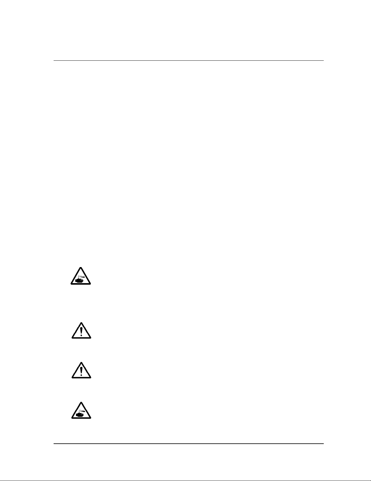
WARNING! HYDROGEN PEROXIDE IS CORROSIVE.
Concentrated hydrogen peroxide is corrosive to skin, eyes, nose, throat, lungs,
and the gastrointestinal tract. Always wear latex, PVC (vinyl), or nitrile gloves
while removing items from the sterilizer following a cancelled cycle. Following a
cancelled cycle, if items in the load show any visible moisture or liquid,
hydrogen peroxide may be present.
WARNING! HYDROGEN PEROXIDE IS AN OXIDIZER.
Avoid allowing hydrogen peroxide to contact organic materials, including paper,
cotton, wood, or lubricants. Concentrated hydrogen peroxide is a strong oxidizer
and may react with organic materials, causing ignition and fire.
WARNING! RISK OF EYE INJURY.
Direct hydrogen peroxide contact with eyes can cause irreversible tissue damage.
If contact with eyes occurs, immediately flush with large amounts of water.
Consult a physician immediately.
WARNING! RISK OF SKIN INJURY.
Direct hydrogen peroxide contact with the skin can cause severe irritation.
If skin contact occurs, immediately flush with large amounts of water.
If symptoms are severe or persist, consult a physician immediately.
STERRAD® NX™ User’s Guide 9
Page 10
2 Safety Information
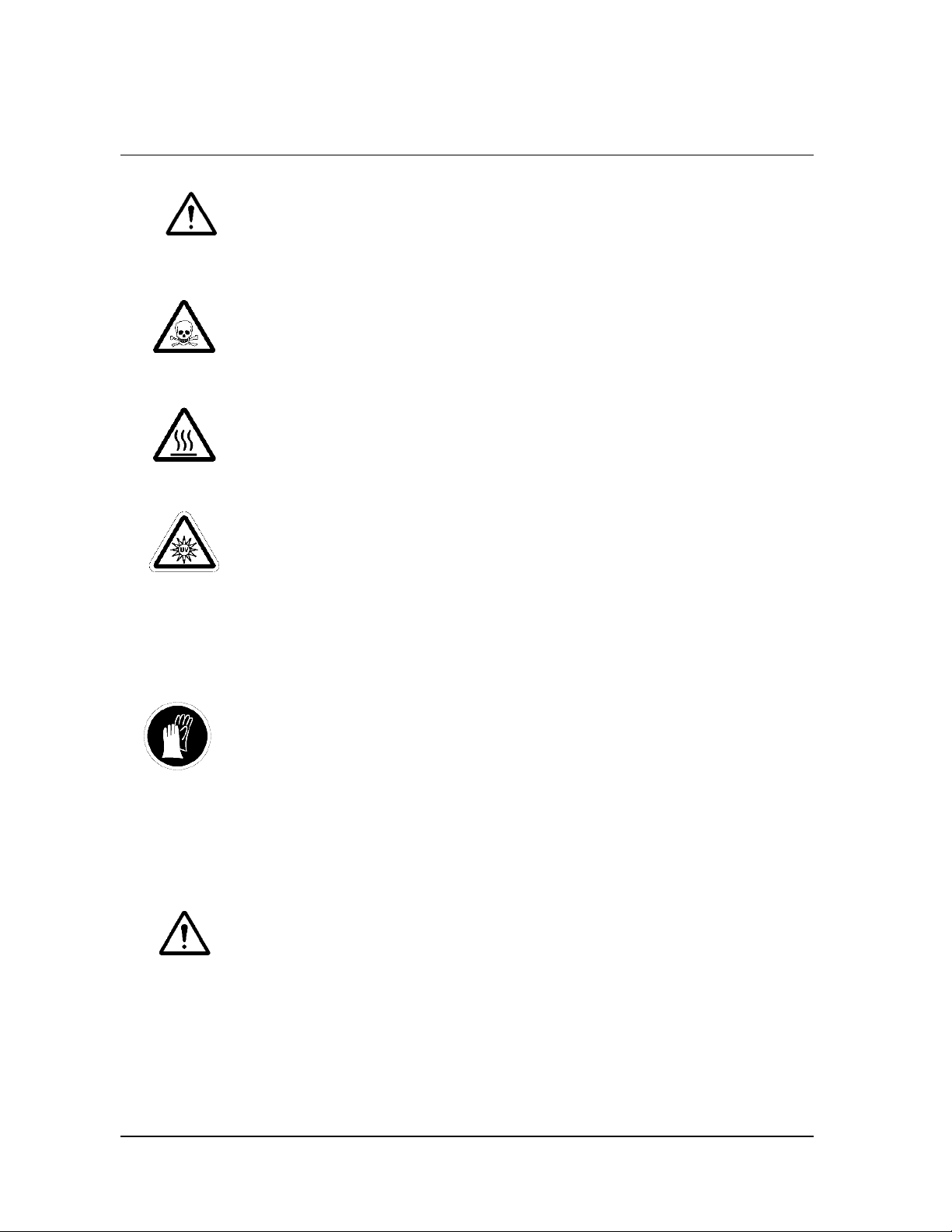
WARNING! RISK OF RESPIRATORY IRRITATION.
Inhalation of hydrogen peroxide mist can cause severe irritation of lungs, throat,
and nose. If inhalation occurs, move to fresh air. Consult a physician
immediately.
WARNING! CONCENTRATED HYDROGEN PEROXIDE IS TOXIC.
Ingestion of hydrogen peroxide may be life-threatening. If swallowed, drink
plenty of water immediately to dilute. Do not induce vomiting. Consult a
physician immediately.
WARNING! STERILIZATION SURFACES.
At the end of a cycle, the interior of the sterilizer may be hot. Do not touch the
inside of the chamber or door with your bare or gloved hands. Allow the
sterilizer to cool before touching interior surfaces.
CAUTION: AVOID EXPOSURE TO ULTRAVIOLET LIGHT.
The hydrogen peroxide monitor uses an ultraviolet light source located inside the
chamber behind the door. To avoid eye injury, do not stare directly at the
ultraviolet light source for an extended period of time.
Personal Protective Equipment
CAUTION! HYDROGEN PEROXIDE MAY BE PRESENT.
Wear latex, PVC (vinyl), or nitrile gloves whenever handling a load after a cycle
cancellation. Hydrogen peroxide liquid may be present on the load or in the
chamber.
Device Safety
CAUTION: RISK OF DAMAGE TO LOAD.
Metal objects must not come into contact with the chamber walls, the door, or the
electrode. Contact with the walls, door, or electrode could damage the sterilizer or
the metal objects.
10 STERRAD® NX™ User’s Guide
Page 11
Safety Information 2
Warnings, Cautions, and Notes
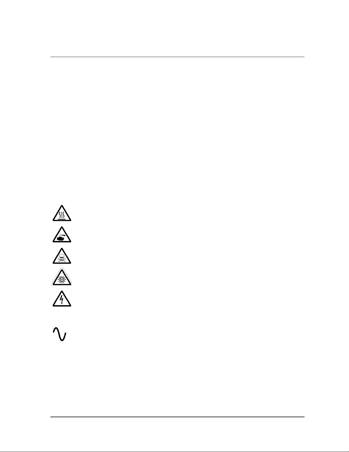
Warnings and cautions are accompanied by symbols surrounded by a triangle and
Ì
are printed in the text in boldface italics. Warnings indicate events or conditions
that can result in serious injury or death. Cautions indicate events or conditions
that can result in severe damage to the equipment.
Notes are accompanied a check mark 4and are printed in italics. Notes
highlight specific information about the proper use and maintenance of the
STERRAD
®
NX Sterilization System.
Symbols Used on the Sterilizer and in This Guide
Hot surfaces present.
Do not touch without protection.
Hazardous chemical present.
Use personal protective equipment.
Toxic chemical present.
Avoid exposure, contact, or ingestion.
Ultraviolet (UV) light hazard.
Do not look at the light without UV eye protection.
High voltage hazard.
I/O
STERRAD® NX™ User’s Guide 11
On/Off.
Alternating current.
Page 12

Page 13

Sterilizer Overview 3
Chapter 3.
Sterilizer Overview
Intended Use
The STERRAD® NX™ Sterilization System is a general purpose, low
temperature sterilizer which uses the STERRAD NX Process to inactivate
microorganisms on a broad range of medical devices and surgical
instruments. This sterilizer offers an effective, safe, fast, economical, easy
to use, reliable, and flexible sterilization method.
When used as directed by the instructions in this user’s guide, the
STERRAD NX Sterilization System will sterilize both metal and nonmetal
medical devices at low temperatures. Please review the “How to Determine
What Can Be Sterilized in the STERRAD NX Sterilizer” chart in the “Load
Preparation” chapter. This chart contains details on recommended
materials and lumen sizes. When selecting reusable medical devices to be
processed in the STERRAD NX Sterilizer, reprocessing information should
be obtained from the manufacturer of the medical device in accordance
with international norms (such as ISO 17664 or AAMI TIR12).
STERRAD® NX™ User’s Guide 13
Page 14

3 Sterilizer Overview
The STERRAD® NX™ Sterilization Process
As a medical professional, you may already be familiar with general
sterilization principles. However, the STERRAD NX Sterilizer represents a
new technology, and it requires special attention to the ways in which it
differs from other sterilizers.
The STERRAD NX Sterilizer sterilizes medical devices by diffusing
hydrogen peroxide vapor into the chamber and then electromagnetically
exciting the hydrogen peroxide molecules into a low-temperature plasma
state. The combined use of hydrogen peroxide vapor and plasma safely and
rapidly sterilizes medical instruments and materials without leaving toxic
residues. All stages of the sterilization cycle operate within a dry
environment at a low temperature, and thus the cycle is not damaging to
compatible instruments sensitive to heat and moisture.
The STERRAD NX Sterilizer can be used for both metal and nonmetal
devices, and can also sterilize instruments that have difficult-to-reach
(diffusion-restricted) spaces, such as hinges on forceps. Refer to the “Safety
Information” chapter for more information.
The sterilizer consistently provides a Sterility Assurance Level (SAL) of
-6
10
, as defined by U.S. Food and Drug Administration (FDA) and
international standards, for clinical use on all allowed substrates within the
limits of the claims for materials and geometries when used in accordance
with the directions in this user’s guide.
The devices have been pre-validated to an SAL of 10
case conditions, including lumens within the claim lengths and mated
surfaces. If additional technical information concerning validation is
needed, please contact your ASP Representative.
-6
based upon worst-
14 STERRAD® NX™ User’s Guide
Page 15

Sterilizer Overview 3
Overview of the STERRAD® NX™ Sterilization Cycle
The STERRAD NX Sterilization Cycle consists of two phases: Exposure 1
and Exposure 2. The following information provides a brief description for
each of the steps.
Exposure 1
♦ Delivery 1: The hydrogen peroxide is transferred from the cassette into
the vaporizer.
♦ Vaporization Pumpdown 1: The pressure within the chamber and
vaporizer/ condenser is reduced. Water is removed from the hydrogen
peroxide solution, leaving behind a concentrated hydrogen peroxide
solution in the condenser.
♦ Chamber Pumpdown 1: The chamber is isolated from the
vaporizer/condenser. The chamber pressure is reduced to remove air
from the lumens.
♦ Transfer 1: The concentrated hydrogen peroxide solution is transferred
to the chamber where it penetrates throughout the load.
♦ Diffusion 1: Chapter pressure is increased in order to drive hydrogen
peroxide is through the load packaging onto the surfaces of the devices
and into the lumens of the load.
♦ Plasma Pumpdown 1 / Plasma 1: Plasma power is applied to the
electrode screen and the plasma is lit.
♦ Vent 1: The chamber is vented to atmospheric pressure.
STERRAD® NX™ User’s Guide 15
Page 16

3 Sterilizer Overview
Exposure 2
The steps in Exposure 1 are repeated.
The STERRAD® NX Sterilization Cycle
Phase Order Stages
Exposure 1
Exposure 2
1
2
Delivery 1
Vaporization Pumpdown 1
Chamber Pumpdown 1
Transfer 1
Diffusion 1
Plasma Pumpdown 1 / Plasma 1
Vent 1
Delivery 2
Vaporization Pumpdown 2
Chamber Pumpdown 2
Transfer 2
Diffusion 2
Plasma Pumpdown 2 / Plasma 2
Final Vent
16 STERRAD® NX™ User’s Guide
Page 17
Sterilizer Overview 3
The STERRAD® NX™ Sterilizer and Features
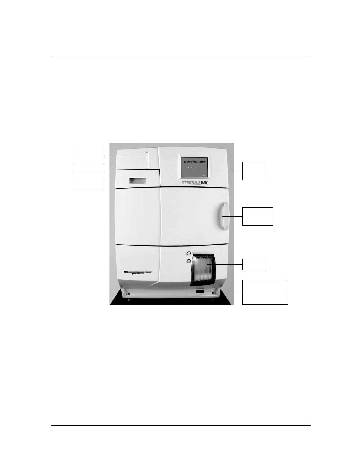
The cassette slot, the cassette drawer, the touch screen, the chamber door,
the printer, and the main power switch are found on the front of the
sterilizer.
Cassette
slot
Touch
Cassette
drawer
screen
Chamber
door
Cassette
Printer
Main power
switch and
circuit breaker
Figure 1. The STERRAD® NX™ Sterilizer.
The cassette contains sealed capsules of precisely measured amounts of
hydrogen peroxide solution. Each cassette contains enough sterilant for five
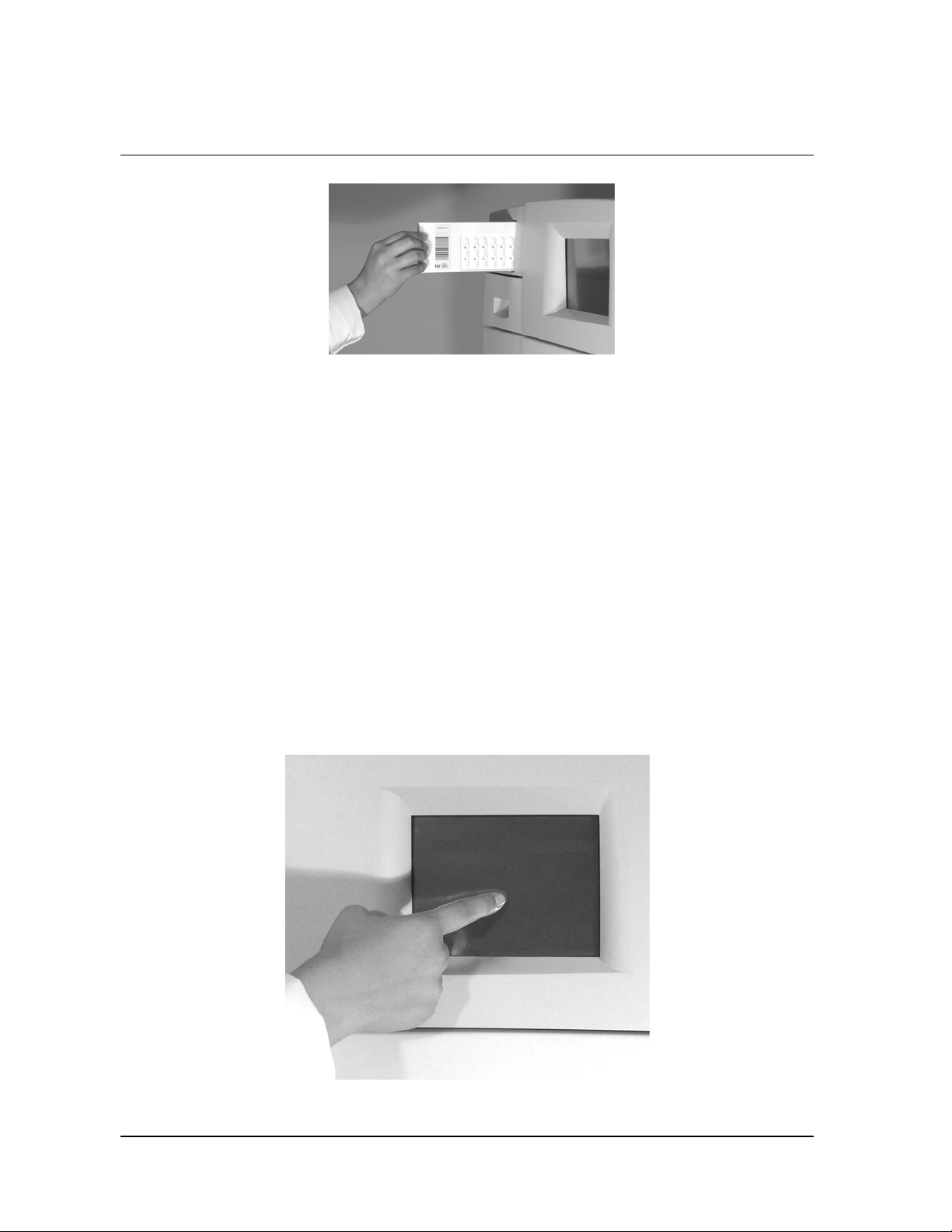
cycles. Cassettes are inserted into the sterilizer through the cassette slot.
The sterilizer pulls the cassette through the slot and moves it into the
machine, keeping it there until the cassette has been processed.
STERRAD® NX™ User’s Guide 17
Page 18
3 Sterilizer Overview
Cassette Drawer
After processing of the cassette, the sterilizer automatically discards it into
the cassette disposal box in the cassette drawer.
Cassette Disposal Box
The cassette drawer contains a cassette disposal box for used cassettes. The
box holds three cassettes. When the box is full, the sterilizer displays a
message indicating that the drawer must be emptied. The cassette disposal
box must be closed to permit safe disposal of cassettes. Refer the
“Maintenance” chapter for additional information.
Figure 2. Inserting a Cassette.
Touch Screen and Speaker
The sterilizer displays information and accepts commands through a color
touch screen. By touching buttons displayed on the screen, you can enter
letters and numbers, make selections, and start and stop the sterilizer.
Figure 3. Using the Touch Screen
18 STERRAD® NX™ User’s Guide
Page 19
Sterilizer Overview 3
An internal loudspeaker emits “beep” tones to call for user attention or
indicate errors. A single long beep indicates a successfully completed cycle.
A series of ten short beeps indicates a canceled cycle.
Chamber
The chamber is where the load is sterilized. The chamber walls and door
contain heaters that keep the chamber interior warm during operation.
When the chamber door is closed, a vacuum-tight seal is created, allowing
the chamber to be evacuated during operation. A locking mechanism
prevents the door from being opened when a sterilization cycle is in
progress.
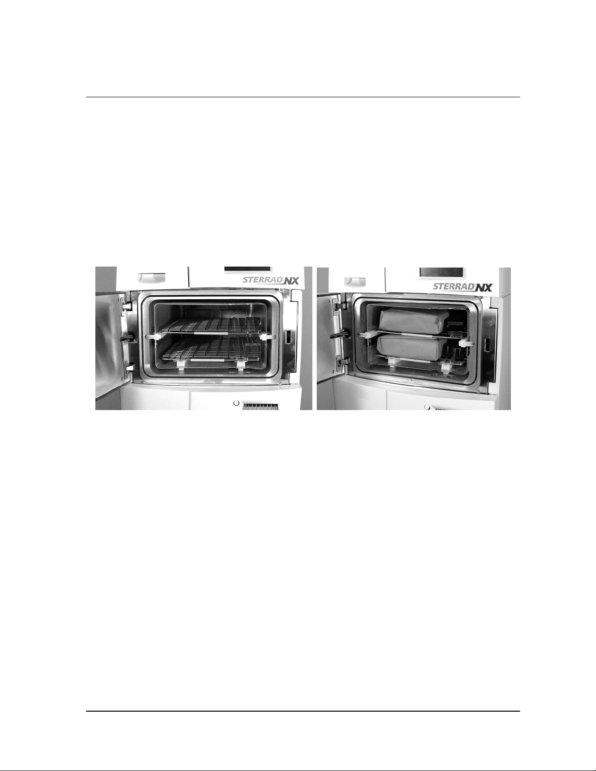
Figure 4. The STERRAD® NX™ Chamber Empty and With the Load Correctly Place.
The chamber contains two slide-out shelves to permit efficient loading; the
top shelf is removable. Inside the chamber, surrounding the shelves, is a
metal screen (the electrode) that helps generate plasma during operation.
STERRAD® NX™ User’s Guide 19
Page 20
3 Sterilizer Overview
Printer
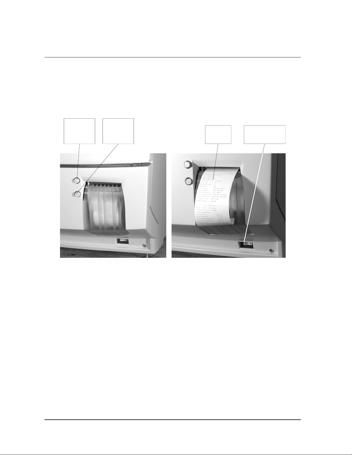
The printer prints cycle reports and other information on a roll of thermal
paper. The printer features easy drop-in paper loading and requires no ink
cartridges. When the sterilizer power is on, the printer interior is
illuminated with a blue light.
Push to
open the
printer
Figure 5. STERRAD® NX™ Printer, Paper Advance Button and Power Switch Details.
Paper
advance
button
The top button opens the printer for paper replacement. The bottom button
advances the paper when pressed. Note the location of the main power
switch under the printer.
Printed
report
Main power
switch
20 STERRAD® NX™ User’s Guide
Page 21
Sterilizer Overview 3
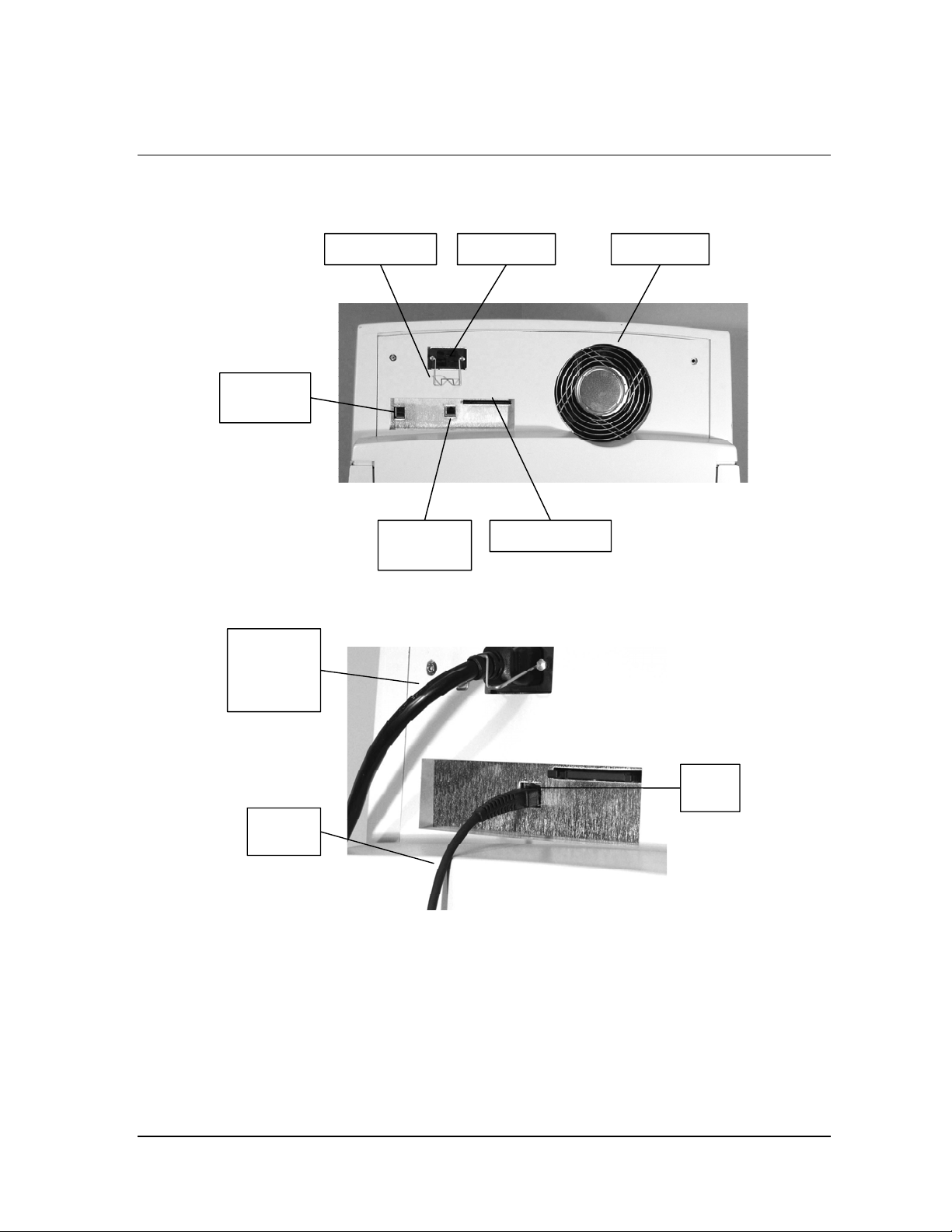
Rear Panel
Wire retainer Power inlet Cooling fan
Option
connector
Network
connector
Figure 6. Rear Panel.
Power cord
secured in
the inlet by
retainer
Network
cable
Figure 7. Connection Panel Located on the Lower Rear of the Sterilizer.
PCMCIA card
RJ-45
socket
STERRAD® NX™ User’s Guide 21
Page 22
3 Sterilizer Overview
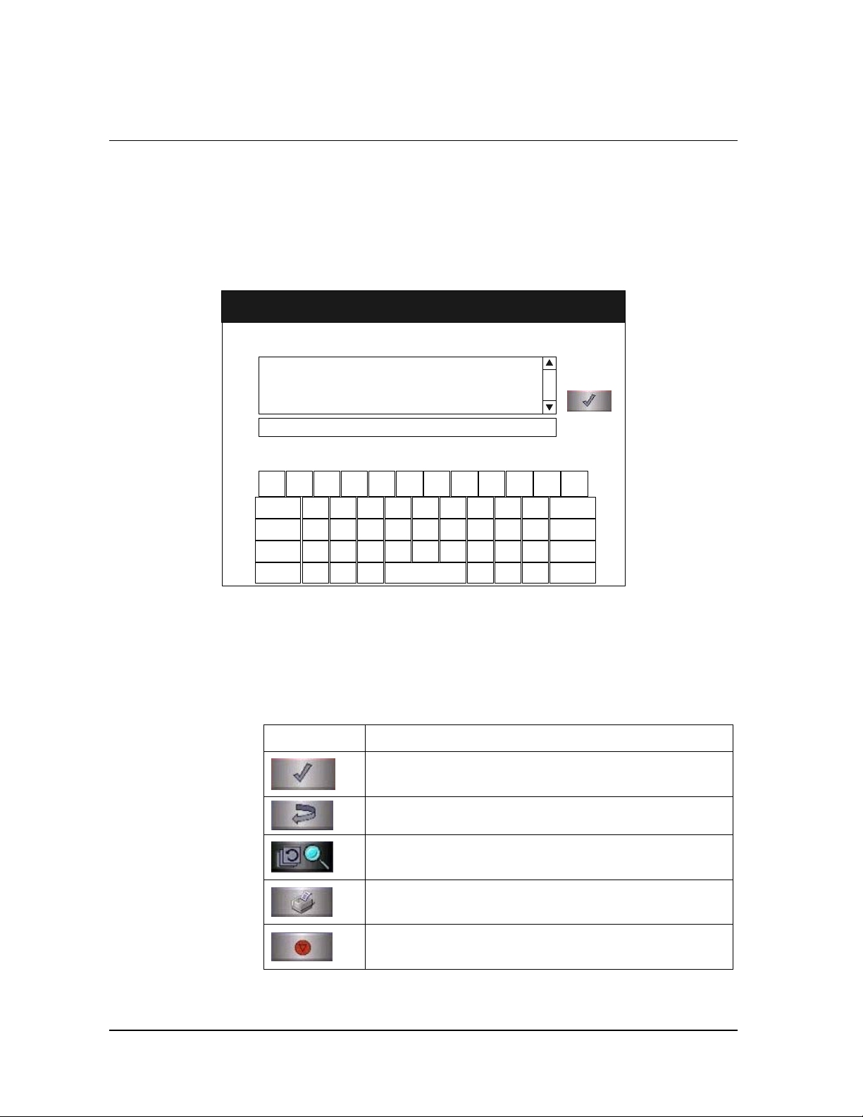
Touch Screen Data Entry
The following figure shows a typical data entry screen. The typewriter
“keys” input the indicated character each time a key is touched. You can
touch the screen with your finger or with a stylus to move the cursor from
place to place.
Enter Load Item Data
ITEM #
Enter
Items
!1@2#3$4%5^6&7*8(9)0_-+
Q
W E R T Y U I O P
~
.
CAP LOCK
BACKSP
Z X C V B N M
ALT
}
{
]
[
TRACKING NUMBER
MM/DD/YY
HH:MM:SS
<,>
?
|
\
Done
=
BACKSP
:
LKJHGFDSA
;
ENTER
.
"
ALT
'
/
Figure 8. Example of an Information Entry Screen.
Most screens provide function buttons that display other screens or select
sterilizer functions. Common function buttons are shown in the following
table.
Function Buttons
Button Function
Done. Touch this button to indicate that you are finished
using the screen.
Back. Touch this button to return to a prior screen.
View. Touch this button to view the selected report or
file.
Print. Touch this button to print the selected report or
file.
Cancel. Touch this button to cancel the entry you just
made.
22 STERRAD® NX™ User’s Guide
Page 23
Sterilizer Overview 3
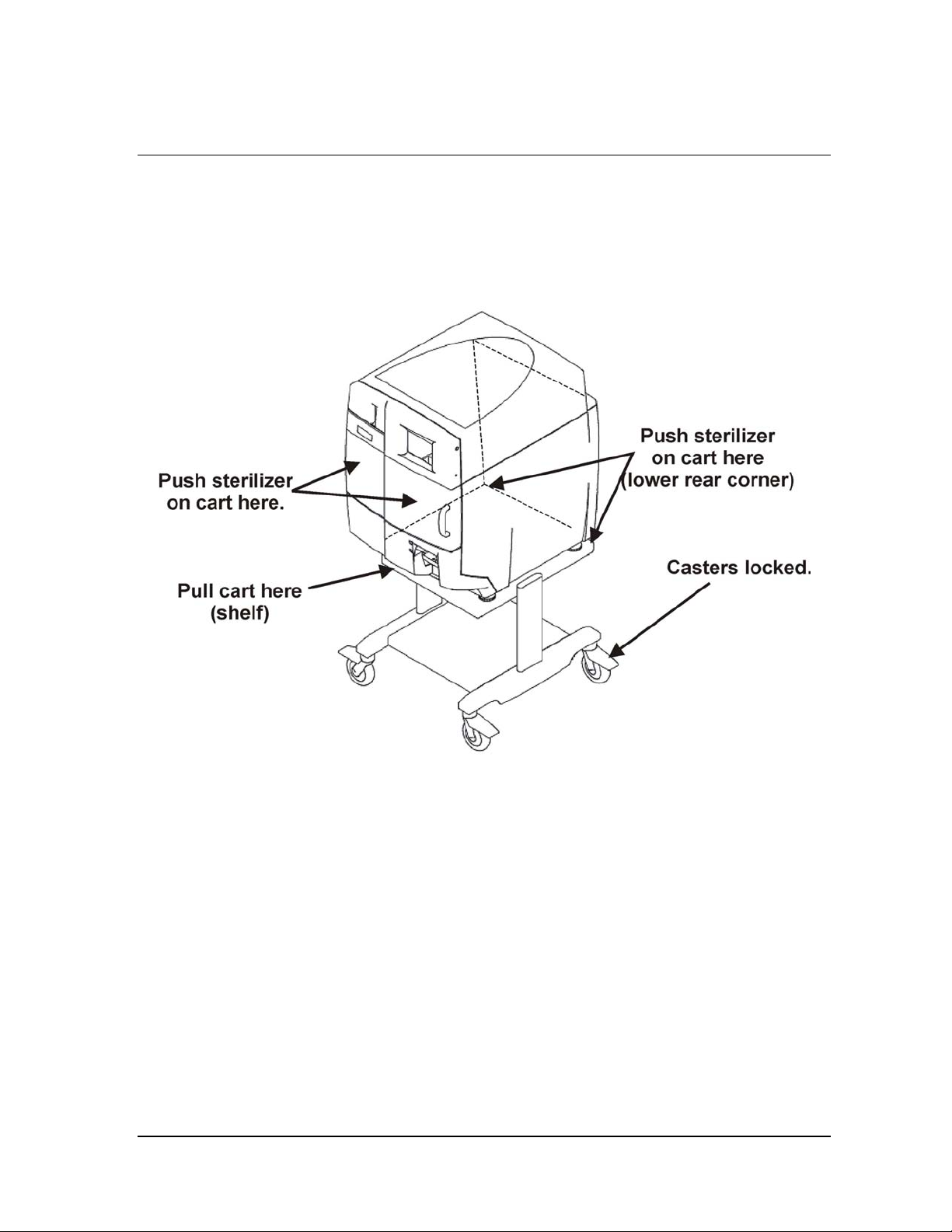
Sterilizer Cart
The Sterilizer Cart is an optional accessory that may be used to hold the
STERRAD
placed upon the cart.
®
NX™ Sterilizer. The following figure shows the sterilizer
Figure 9. Sterilizer Cart
The casters may be locked and unlocked by pressing on caster levers. In
order for the cart to have maximum stability, the casters should be oriented
in the locked position as shown in the figure above.
The sterilizer may be pulled and pushed as shown in the figure above. DO
NOT push or pull the sterilizer sideways as this is the least stable
orientation. DO NOT move the sterilizer with the door open. DO NOT use
the door handle to move the sterilizer.
The next chapter describes how to use the STERRAD NX Sterilizer to
sterilize your items.
STERRAD® NX™ User’s Guide 23
Page 24

Page 25

Load Preparation 4
Chapter 4.
Load Preparation
Indications for Use
The STERRAD
and nonmetal medical devices at low temperatures. The STERRAD
sterilization process is a multiphase sterilization process that utilizes a
combination of exposure to hydrogen peroxide vapor and plasma to affect
sterilization. The STERRAD NX Sterilizer can sterilize instruments which
have diffusion-restricted spaces, such as the hinged portion of forceps and
scissors.
®
NX™ Sterilizer is designed for sterilization of both metal
Medical devices with the following materials and dimensions can be
processed in the STERRAD NX Sterilizer Standard cycle:
♦ Single-channel stainless steel lumens with an inside diameter of 1 mm
or larger and a length of 150 mm or shorter.
♦ Single-channel stainless steel lumens with an inside diameter of 2 mm
or larger and a length of 400 mm or shorter. †
Medical devices, including most flexible endoscopes, with the following
materials and dimensions can be processed in the STERRAD NX Sterilizer
Advanced cycle:
♦ Single-channel stainless steel lumens with an inside diameter of 1 mm
or larger and a length of 500 mm or shorter.
♦ Single-channel PE/PTFE flexible endoscopes with an inside diameter
of 1 mm or larger and a length of 850 mm or shorter.*
†
The validation testing for this lumen size was conducted using a maximum of 10 lumens
per load. Hospital loads should not exceed the maximum number of lumens validated by this
testing.
*Only one flexible endoscope per cycle with or without a silicone mat. No additional load.
Teflon® is a registered trademark of E.I. du Pont de Nemours and Company.
†
†
STERRAD® NX™ User’s Guide 25
Page 26

4 Load Preparation
4 Note: With the exception of the 1 x 850 mm flexible
endoscopes, the validation studies were performed
using a validation load consisting of one instrument
tray weighing 10.7 lbs. The 1 x 850 mm flexible
endoscopes were validated without any additional
load.
Determining What Can be Sterilized
in the STERRAD® NX™ Sterilizer
CAUTION: RISK OF DAMAGE TO LOAD OR STERILIZER.
Do not attempt to sterilize items or materials that do not comply with the guidelines
specified in this user’s guide. Consult the medical device manufacturer’s
instructions or call the ASP Customer Care Center to determine if an item can be
sterilized by the STERRAD NX Sterilization System.
Recommended Materials and Lumen Chart
The following page includes a chart that unfolds to show you detailed lists
of recommended items, materials, and some typical devices that can be
sterilized in the STERRAD NX Sterilizer. Please refer to it whenever you
need materials information. Be sure to check the medical device
manufacturer’s instructions before loading any item into the
STERRAD NX Sterilizer.
There are a wide variety of materials and devices that can be sterilized in
the STERRAD NX Sterilizer. As more manufacturers complete testing of
their products with the STERRAD NX Sterilizer, the list of compatible
items continues to grow. Information in the chart included in this
publication is updated as new information becomes available. ASP
maintains this updated information and we are happy to share it with you.
Please contact the ASP Customer Care Center for an up-to-date list of
recommended materials, devices and/or device manufacturer information.
Information may also be obtained from the device manufacturer. In the
U.S.A., call 1-888-783-7723, internationally call your local ASP Customer
Care Representative or contact us through our website – www.sterrad.com.
26 STERRAD® NX™ User’s Guide
Page 27

Load Preparation 4
ASP has validated the processing of non-reusable polyethylene and Teflon
(polytetrafluoroethylene) medical grade tubing with the dimension and
cycles listed below. These tubing claims have not been reviewed by the
Food and Drug Administration (FDA):
♦ An inside diameter of 1 mm or larger and a length of 350 mm or shorter
can be processed in the STERRAD NX Sterilizer Standard cycle.
♦ An inside diameter of 1 mm or larger and a length of 1000 mm or
shorter can be processed in the STERRAD NX Sterilizer Advanced
cycle.*
The FDA has not reviewed these tubing claims as the FDA does not
classify tubing as medical devices.
Items Not To Be Processed
♦ Single use items for which the manufacturer does not recommend
resterilization.
♦ Liquids and powders.
♦ Items or materials that absorb liquids.
♦ Items made of materials that contain cellulose, such as cotton, paper or
cardboard, linens, huck towels, gauze sponges, or any item containing
wood pulp.
®
†
♦ Paper instrument count sheets or lot stickers.
♦ Items with mated Nylon
®
surfaces.
♦ Instruments and devices that cannot withstand a vacuum and are
labeled for gravity steam sterilization methods only.
♦ Items whose design permits the surfaces to collapse onto each other
unless some method is used to keep the surfaces separated.
♦ Dead-end lumens must not be processed.
♦ Devices with internal parts, such as sealed bearings, that cannot be
immersed may present difficulties in cleaning and should not be
processed in the STERRAD NX Sterilizer.
†
The validation testing for this lumen size was conducted using a maximum of 10 lumens
per load. Hospital loads should not exceed the maximum number of lumens validated by
this testing.
*Sterilize without any additional load. Up to 10 pieces of tubing may be sterilized at one
time.
®
is a registered trademark of E.I. du Pont de Nemours and Company.
Nylon
STERRAD® NX™ User’s Guide 27
Page 28

4 Load Preparation
♦ Instrument mats other than STERRAD Instrument Mats.
♦ Instrument trays other than STERRAD Instrument Trays or
APTIMAX
♦ Implants for which the manufacturer has not specifically recommended
sterilization in the STERRAD
®
Instrument Trays.
®
NX Sterilizer.
Guidelines for Preparing Items to Be Sterilized
4 Note: All items must be cleaned, rinsed, and thoroughly
dried before being placed in the STERRAD NX
Sterilizer. Loads containing moisture may cause
cycle cancellations.
Cleaning, Rinsing, and Drying
Cleaning and sterilization are two separate processes. As with all
sterilization methods, proper cleaning of instruments and devices is a
critical and necessary step prior to sterilization. All items must be cleaned,
rinsed, and thoroughly dried before loading into the sterilizer. Carefully
inspect all instruments and devices for cleanliness and dryness and for
flaws or damage prior to packaging. If visible soil or moisture is present,
the item must be re-cleaned and dried prior to sterilization. Devices and
instruments with flaws or damage should be replaced or repaired before
using.
The process of cleaning is necessary to remove organic and inorganic soil
and debris from equipment. In this process, many microorganisms are
removed from the surface of the items. The process of sterilization
inactivates all remaining spores and live microorganisms.
♦ Remove all blood, tissue, and soil from items by following the device
manufacturer’s instructions using an appropriate detergent or cleanser.
♦ Rinse items thoroughly to remove detergent or cleanser residue.
♦ Dry all items thoroughly. An acceptable method for drying is to blow
compressed gas through the lumen until no moisture exits the distal end
of the device. Please ensure that any method used to dry the devices is
in accordance with the manufacturer’s instructions for use or contact
the device manufacturer to obtain appropriate and safe procedures. It is
necessary to remove moisture from all parts of the items. Only dry
items should be loaded into the sterilization chamber to prevent
cycle cancellation.
28 STERRAD® NX™ User’s Guide
Page 29

Load Preparation 4
♦ Some complex reusable medical devices may require disassembly for
proper cleaning and sterilization. It is very important that you follow
the device manufacturers recommendations concerning cleaning and
sterilization.
WARNING! POSSIBLE NON-STERILE DEVICE
Loads containing moisture may result in either a non-sterile device or cycle
cancellation.
4 Note: Periodic careful inspection of items after repeated
exposure to disinfectant/cleaner/ sterilant is
necessary, due to the potential damaging effects of
the chemical agent on the items.
Packaging and Loading
If you choose to package the instruments, proper preparation of trays,
pouches, and instruments can minimize or prevent cycle cancellations and
positive biological indicator (BI) results due to load-related problems. All
instruments must be cleaned, rinsed, and thoroughly dried before loading
into the sterilizer.
Instrument Trays
♦ Only STERRAD Instrument Trays, APTIMAX® Instrument Trays, and
Tray Mats
♦ Instrument trays should only be padded with STERRAD Instrument
♦ Follow the Instructions for Use included with the STERRAD
♦ Do not use foam pads in instrument trays. They may absorb the
STERRAD accessories are recommended for use in the
STERRAD NX Sterilizer. These instrument trays are specially
designed to allow diffusion of hydrogen peroxide and plasma around
every item in the load.
Mats or polypropylene sterilization wrap. Never use linen, cellulose, or
any materials in the “Items Not To Be Processed” section.
Instrument Mats to determine the number of mats that can be used at
one time in the chamber. Do not use more than 174 square inches (1123
sq. cm) of mat material in the chamber at any time.
hydrogen peroxide.
STERRAD® NX™ User’s Guide 29
Page 30

4 Load Preparation
Packaging
♦ Use only STERRAD Sterilizer-compatible polypropylene sterilization
wrap and Tyvek
♦ Do not use paper pouches or sterilization wraps containing cellulose or
cotton.
♦ Do not use any wraps or packaging that are not approved by ASP or
materials on the “Items Not To Be Processed” section.
♦ Arrange the items in a tray to ensure proper diffusion of hydrogen
peroxide throughout the load.
♦ Place peel pouches on edge, if possible. Arrange them so that the
transparent side of a pouch faces the opaque side of the next pouch. Do
not stack pouches on top of each other.
♦ Do not stack instruments inside the trays. Do not stack trays. Do not
stack trays within trays. Do not wrap instruments within a wrapped
tray.
♦ If you are using rigid containers cleared by the FDA for use in the
STERRAD NX Sterilizer, follow the same procedures that are
recommended for use with the STERRAD Instrument Trays or
APTIMAX
containers. Do not stack containers. Do not stack containers within
containers. Do not wrap instruments within the containers.
®
pouches.
®
Instrument Trays. Do not stack instruments inside the
♦ Place STERRAD Chemical Indicator Strips inside trays and pouches as
needed.
Loading
♦ Do not allow any item to touch the walls of the sterilization chamber,
door, or electrode.
CAUTION: RISK OF DAMAGE TO LOAD OR STERILIZER.
Assure that metal objects do not come into contact with the walls of the chamber,
door, or electrode. Contact with the walls, door, or electrode can cause a cycle
cancellation, and/or damage the item or the sterilizer. Provide at least 1 inch (25
mm) of space between the top of the load and the electrode.
Tyvek® is a registered trademark of E.I. du Pont de Nemours and Company.
30 STERRAD® NX™ User’s Guide
Page 31

Load Preparation 4
Chemical Indicators
STERRAD® Chemical Indicator Strips and STERRAD® SealSure®
Chemical Indicator Tape offer a method to verify that the load has been
exposed to hydrogen peroxide in the sterilizer. Chemical indicators are not
a substitute for biological indicators.
If you use chemical indicator strips or chemical indicator tape, follow the
Instructions for Use that accompany these items as you prepare the load.
♦ Place STERRAD® Chemical Indicator Strips inside trays and Tyvek®
pouches.
♦ Secure all wraps with STERRAD
♦ Do not use chemical indicators designed for other sterilization
processes.
®
SealSure® Chemical Indicator Tape.
Tyvek® is a registered trademark of E.I. du Pont de Nemours and Company.
STERRAD® NX™ User’s Guide 31
Page 32

Page 33

Operation 5
Chapter 5.
Operation
Before You Start
Each time you use the STERRAD® NX™ Sterilizer, follow the instructions
provided in the chapter on load preparation. It is the operator’s
responsibility to be familiar with the information provided in this user’s
guide.
Start and Warm-up
1. Turn on the main power switch–it is located at the front of the
sterilizer, below the printer.
2. Close the door. The sterilizer begins by warming up. The warm-up can
take up to 30 minutes.
3. “Touch Screen to Start” appears on the display.
STERRAD® NX™ User’s Guide 33
Page 34

5 Operation
STERRAD NX System
TOUCH SCREEN TO START
Figure 10. Touch the Screen to Start Your Cycle
The screen displays the message “Please Insert New Cassette” if a new
cassette is required, if the cassette in the sterilizer is expired, or if there is
no cassette installed in the sterilizer. Follow the instructions in the next
section to insert a new cassette.
If the sterilizer is loaded with an unexpired cassette, skip to the subsection
titled “Preparing the Load.”
®
®
Inserting a Cassette
1. Take a new STERRAD NX Cassette out of the shipping carton.
2. Look at the package carefully before opening it. The indicator strip
should be a yellow color. If the indicator strip is red, do not open the
package–it is possible that hydrogen peroxide has leaked inside the
package. Refer to the cassette Instructions for Use for proper handling
instructions.
3. If the indicator strip is yellow, open the cassette package.
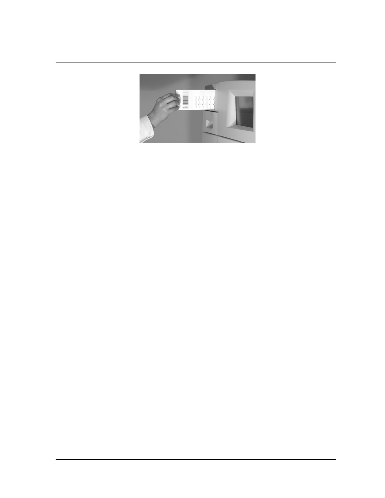
4. Insert the cassette into the cassette slot until it stops moving as shown
in the following figure. Do not use force to push the cassette into the
machine.
34 STERRAD® NX™ User’s Guide
Page 35
Operation 5
Figure 11. Inserting the Cassette into the Slot.
5. After a slight pause, the sterilizer pulls the cassette through the slot and
the slot door closes. Cassette loading is now complete.
Preparing the Load
While the sterilizer is warming up, you can use this time to prepare the
load. Refer to the chapter detailing load preparation information.
Biological Indicators
Confirming that sterilizing conditions were achieved during a cycle is an
important part of the sterilization process. Biological indicators are one way
to ensure that your sterilizer is operating correctly. ASP recommends using
the STERRAD
Representative regarding biological indicators specifically designed for use
in the STERRAD NX Sterilizer.
Place a STERRAD® CycleSure® Biological Indicator in the chamber at the
back of the bottom shelf. Biological testing should be performed at least
once per day or as specified by your facility’s policy. Review the
instructions for use included with the biological indicator to ensure its
proper use.
Login
4 Note: If your sterilizer has been configured not to require
When you touch the “Touch Screen to Start” screen, the sterilizer displays
the Operator Login screen.
®
CycleSure® Biological Indicator. Contact your ASP
operator login, the login screen will not appear. Skip
to the subsection titled Entering Load Information.
STERRAD® NX™ User’s Guide 35
Page 36
5 Operation
Operator Login
Operator:
Password:
!1@2#3$4%5^6&7*8(9)0_-+
Q
W E R T Y U I O P
~
.
CAP LOCK
BACKSP
Z X C V B N M
}
{
ALT
]
[
MM/DD/YY
HH:MM:SS
|
\
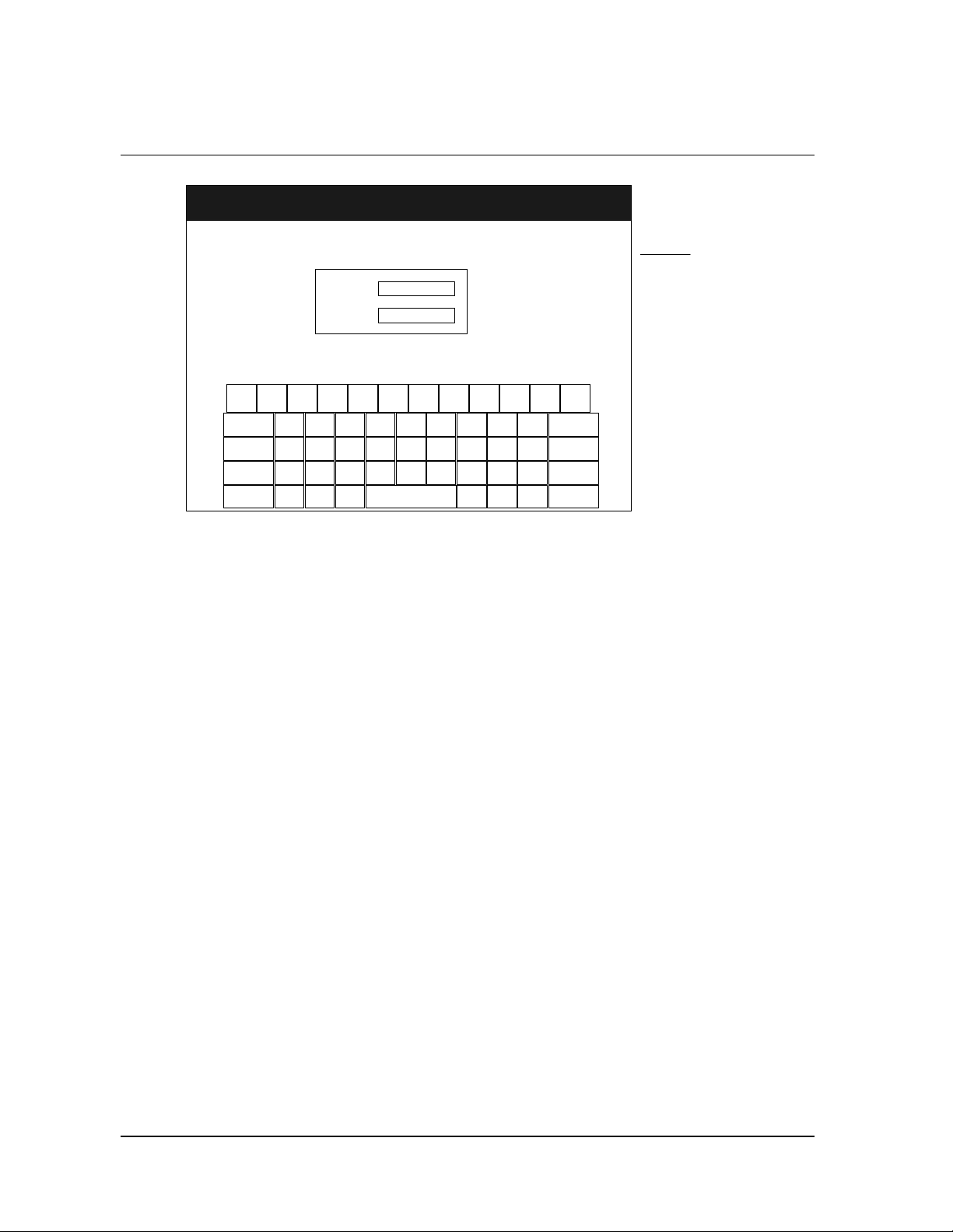
Figure 12. Operator Login Screen.
1. Touch the Operator field. The cursor appears in the field.
4 Note: Operator and Password fields are case-sensitive.
2. Use the on-screen keyboard to type your assigned operator
identification.
<,>
?
/
Legend
MM: month
DD: day
YY: year
HH: hour
MM: minute
SS: second
=
BACKSP
:
LKJHGFDSA
;
ENTER
.
"
ALT
'
3. Touch the Enter key. The cursor jumps to the Password field.
4. Type your password. The screen displays a series of “*” characters in
place of the characters you type. This is done to keep others from
reading your password.
5. When you have finished entering your password, touch the Enter key.
36 STERRAD® NX™ User’s Guide
Page 37
Operation 5
Entering Load Information
4 Note: If your sterilizer has been configured not to require
load item data, this screen will not appear. Skip to
the subsection titled Cycle Notes.
Enter Load Item Data
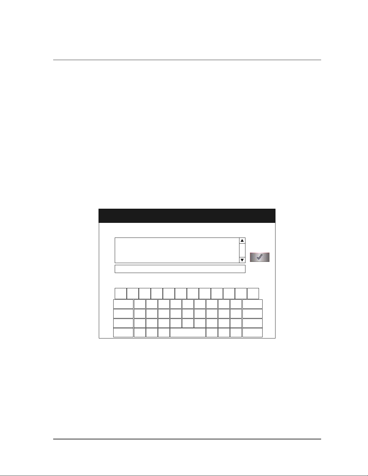
The Load Item Data screen allows you to enter information about the
contents of the load. This can be done for tracking and traceability or may
be useful for inventory purposes.
The Load Item Data screen allows you to enter a list of items in your load
and their associated tracking numbers (if any). This information is stored
by the sterilizer and is printed on a cycle report (and can be transferred to a
host computer over the network connection).
Enter Load Item Data
ITEM #
Enter
Items
!1@2#3$4%5^6&7*8(9)0_-+
Q
W E R T Y U I O P
~
.
CAP LOCK
BACKSP
Z X C V B N M
ALT
}
{
]
[
TRACKING NUMBER
MM/DD/YY
HH:MM:SS
<,>
?
|
/
\
LKJHGFDSA
.
"
'
Done
=
BACKSP
:
;
ENTER
ALT
Figure 13. Enter Load Item Data
1. Touch the Enter Items field. The cursor appears in the field.
2. Use the on-screen keyboard to type a description of each item or its
tracking number.
3. When you have entered an item, touch the Enter key. The line you
typed moves to the list box.
4. Continue entering information, one line at a time, until you are
finished.
5. When data entry is complete, touch the Done button.
STERRAD® NX™ User’s Guide 37
Page 38
5 Operation
Cycle Notes
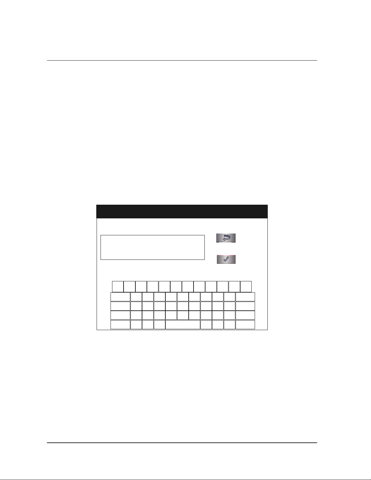
6. The program displays the Enter Cycle Notes screen.
A barcode scanner can also be used to enter load item data. Refer to the
barcode scanner Instructions for Use if your sterilizer is equipped with this
option.
4 Note: If your sterilizer has been configured not to require
cycle notes, this screen will not appear. Skip to the
subsection titled “Loading the Chamber.”
The Cycle Notes screen allows you to enter information about the cycle.
This screen can be used to record information about biological indicators
used in the cycle or any other information that should be stored in the cycle
history file. This information is printed out on the cycle report (and can be
transferred to a host computer over the network connection).
Cycle Notes
Enter Notes For Cycle
!1@2#3$4%5^6&7*8(9)0_-+
Q
W E R T Y U I O P
~
.
CAP LOCK
BACKSP
Z X C V B N M
}
{
ALT
]
[
|
\
Figure 14. Cycle Notes.
MM/DD/YY
HH:MM:SS
Back
Done
<,>
?
/
LKJHGFDSA
.
"
'
=
BACKSP
:
;
ENTER
ALT
38 STERRAD® NX™ User’s Guide
Page 39
Operation 5
1. Touch the Enter Notes for Cycle field. The cursor appears in the field.
2. Use the on-screen keyboard to type your notes.
3. When data entry is complete, touch the Done button.
4. If conditions exist which prevent a sterilization cycle from starting
(e.g., no cassette, hydrogen peroxide monitor blocked), a message is
displayed on the screen.
5. The program displays the System Ready screen.
Loading the Chamber
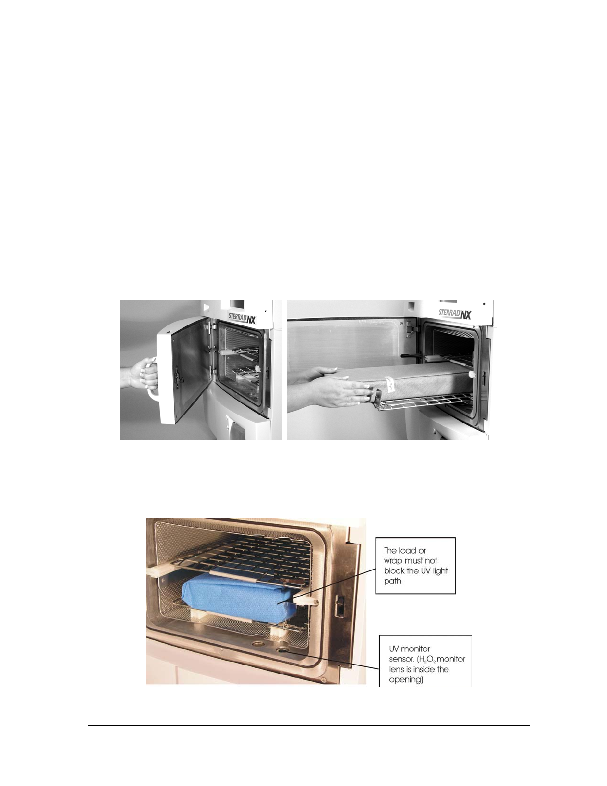
1. Open the chamber door and place your load on the shelves.
Figure 15. Open the Door and Place your Load on the Shelf.
4 Note: If necessary, the top shelf can be removed to
accommodate a large load placed on the bottom
shelf.
Figure 16. Do Not Block the UV Lamp.
STERRAD® NX™ User’s Guide 39
Page 40
5 Operation
2. When placing the load on the shelves, make certain that you do not
block the beam of the ultraviolet lamp in the front right corner of the
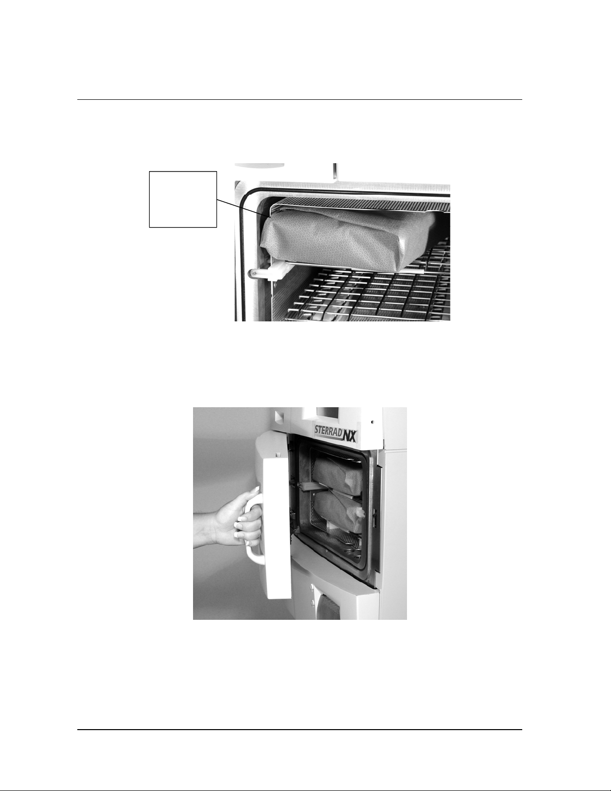
chamber.
Do not allow
the load to
touch the
electrode
Figure 17. The Load Should NOT Touch the Electrode.
3. Do not allow any part of the load to touch the electrode, the back wall
of the chamber, or the inside of the door.
4. Leave at least 1 inch (25 mm) of free space between the load and the
electrode to allow hydrogen peroxide to diffuse around the load.
Figure 18. Close the Door.
5. When finished loading the chamber, close the door tightly.
6. If the message “Please Close Door” is displayed, the door is not
securely closed. Make certain that nothing is caught in the door seal.
40 STERRAD® NX™ User’s Guide
Page 41
Operation 5
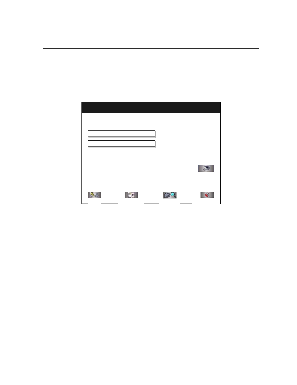
Selecting and Starting a Cycle
When the load has been placed in the chamber, and the door has been
tightly closed, use the System Ready screen to select the sterilization cycle
appropriate for the load.
System Ready
SELECT CYCLE TO BEGIN
STANDARD CYCLE
ADVANCED CYCLE
Logout System Summary Cycle History Additional Utilities
Figure 19. System Ready.
MM/DD/YY
HH:MM:SS
Back
1. Touch the button that corresponds to the cycle that is appropriate for
the load you wish to sterilize.
2. The sterilizer loads the cycle program and displays the Start Cycle
button.
3. If an incorrect cycle has been selected, touch the Cancel button and
then select the correct cycle.
4. Touch the Start Cycle button to start the selected cycle.
STERRAD® NX™ User’s Guide 41
Page 42

5 Operation
Cycle Warm Up
When changing from one type of cycle to another; i.e., from Standard to
Advanced or from Advanced to Standard, the sterilizer requires time to
warm up.
1. The sterilizer displays the System Warming Up message.
System Warming Up...
Cycle Will Automatically Start
Figure 20. System Warming Up,
Cancel Cycle
2. The message provides a cancel button to allow the user to cancel the
cycle.
3. If the sterilizer temperature does not reach the setpoints within 10
minutes, the sterilizer returns to the System Ready screen and the
display directs you to the proper action.
4. Once the temperatures are within the correct range, the sterilizer begins
a “count down clock” as described in the “Cycle In Progress” section.
System Ready Screen
The System Ready screen displays a row of buttons along the bottom of the
screen. These buttons select sterilizer functions:
♦ Logout is used when the current operator is finished using the
sterilizer. When Logout is selected, you must login to use the sterilizer.
♦ System Summary displays the System Summary file and allows you to
print a copy.
♦ Cycle History displays the Select Cycle History screen. This screen
allows you to select a cycle history file and view or print it.
♦ Additional Utilities is available only to operators with Supervisor-
level access. It displays the Additional Utilities Menu.
42 STERRAD® NX™ User’s Guide
Page 43
Operation 5
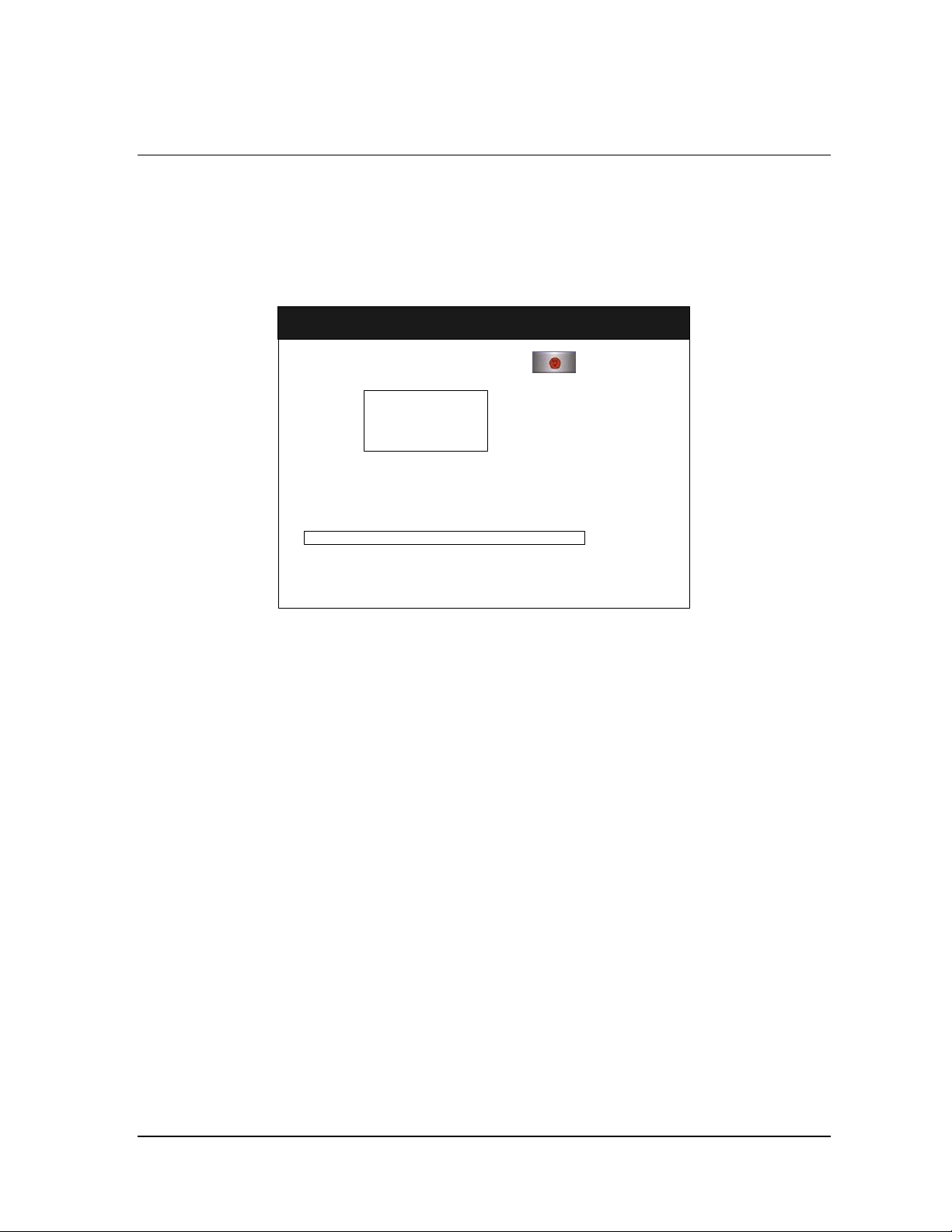
Cycle in Progress
When you touch the Start Cycle button, the sterilizer starts a “countdown
clock” and begins the sterilization cycle.
Cycle In Progress
MM:SS
Time Remaining
Current Stage: xx
x %
MM/DD/YY
HH:MM:SS
Cancel Cycle
Figure 21. Cycle In Progress. The Countdown Clock is Displayed.
The clock displays the estimated number of minutes and seconds remaining
before the cycle is finished. The “Time Remaining” field updates as the
sterilization cycle progresses. As each sterilization cycle stage runs, the
screen displays the name of the stage. A moving bar graph also displays the
percent of the cycle that is complete. For details about the current stage
information, refer to the Long Report printout in the “Reports and Files”
chapter.
Canceling a Cycle
There may be occasions when it is necessary to cancel a cycle before it is
completed.
To cancel a cycle, do the following:
1. Touch the Cancel Cycle button. The screen displays a confirmation
message.
STERRAD® NX™ User’s Guide 43
Page 44
5 Operation
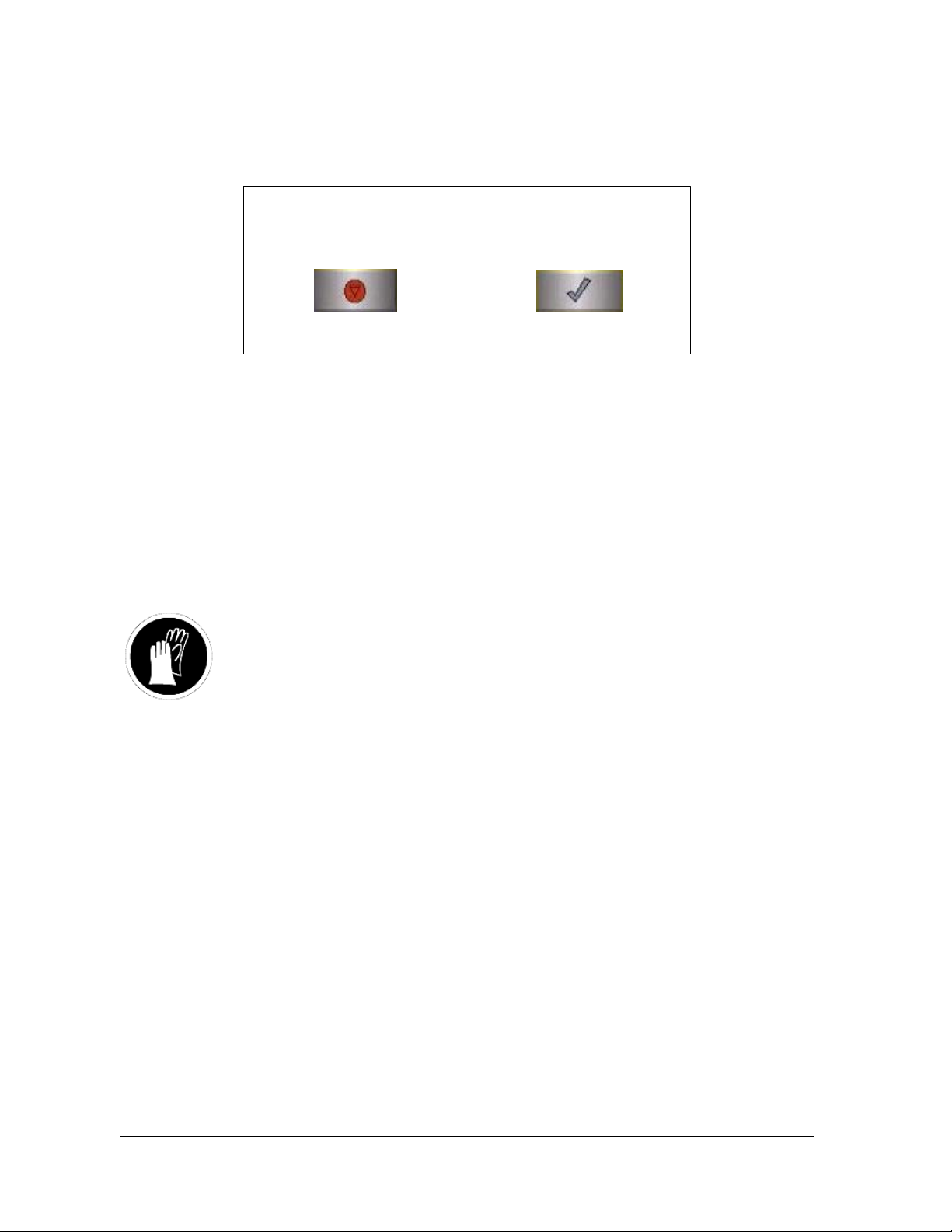
Cancel Cycle?
NO YES
Figure 22. Cancel Cycle Confirmation. Touch Yes or No.
2. Touch the No button to proceed with the cycle. Touch the Yes button to
cancel the cycle. Once the cycle cancellation sequence begins, the
screen turns red and the cancellation sequence cannot be interrupted.
The cancellation sequence may take up to ten minutes to complete.
Loads from canceled cycles should be rewrapped using new packaging
materials, STERRAD
SealSure
the canceled load, the previously used biological indicator must be
discarded and a new biological indicator must be placed in the chamber
before restarting the new cycle.
WARNING! HYDROGEN PEROXIDE MAY BE PRESENT.
If a cycle cancels and the items in the load appear wet, hydrogen peroxide
may be present. Wear latex, PVC (vinyl), or nitrile gloves while removing
the items from the chamber, and while wiping off the items with a damp
cloth.
®
Chemical Indicator Tape. If a biological indicator was used in
Cycle Completed
When the cycle is complete, the Cycle Completed screen is displayed. The
background of the screen is green to indicate a successfully completed
cycle. The loudspeaker emits one long beep to indicate successful cycle
completion.
®
Chemical Indicator Strips, and STERRAD®
44 STERRAD® NX™ User’s Guide
Page 45

Operation 5
Cycle Completed
Cycle Completed Successfully
CYCLE DATA:
Cycle #:
Cycle Name:
Start Time:
Completion Time:
Elapsed Time:
Operator:
MM/DD/YY
HH:MM:SS
DoneView Details
Figure 23. Cycle Completed.
1. Touch the View Details button to display the cycle history file for the
just-completed cycle.
2. Touch the Done button to proceed.
Processing a Sterilized Load
When you touch the Done button, how the sterilizer responds depends upon
the configuration of your sterilizer.
♦ If login is required before the door can be opened, the Login screen is
displayed. When this occurs, enter your operator identification and
password and touch the Done button. The door unlocks and the load
can be removed.
♦ If no login is required for load removal, the door unlocks and the load
can be removed.
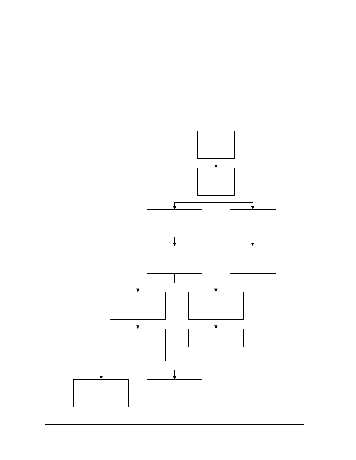
♦ Refer to the cycle completion flowchart on the next page for additional
information.
Inspecting Chemical Indicators
After ensuring that the chemical indicators exhibit the correct color change,
and the cycle printout shows that all parameters were met, the sterilized
load is ready for immediate use, following your facility’s policy. If the
chemical indicators do not exhibit the correct color change, investigate the
cause and repackage and reprocess the load.
STERRAD® NX™ User’s Guide 45
Page 46
5 Operation
Processing Biological Indicators
Remove the biological indicator from the load and process it per its
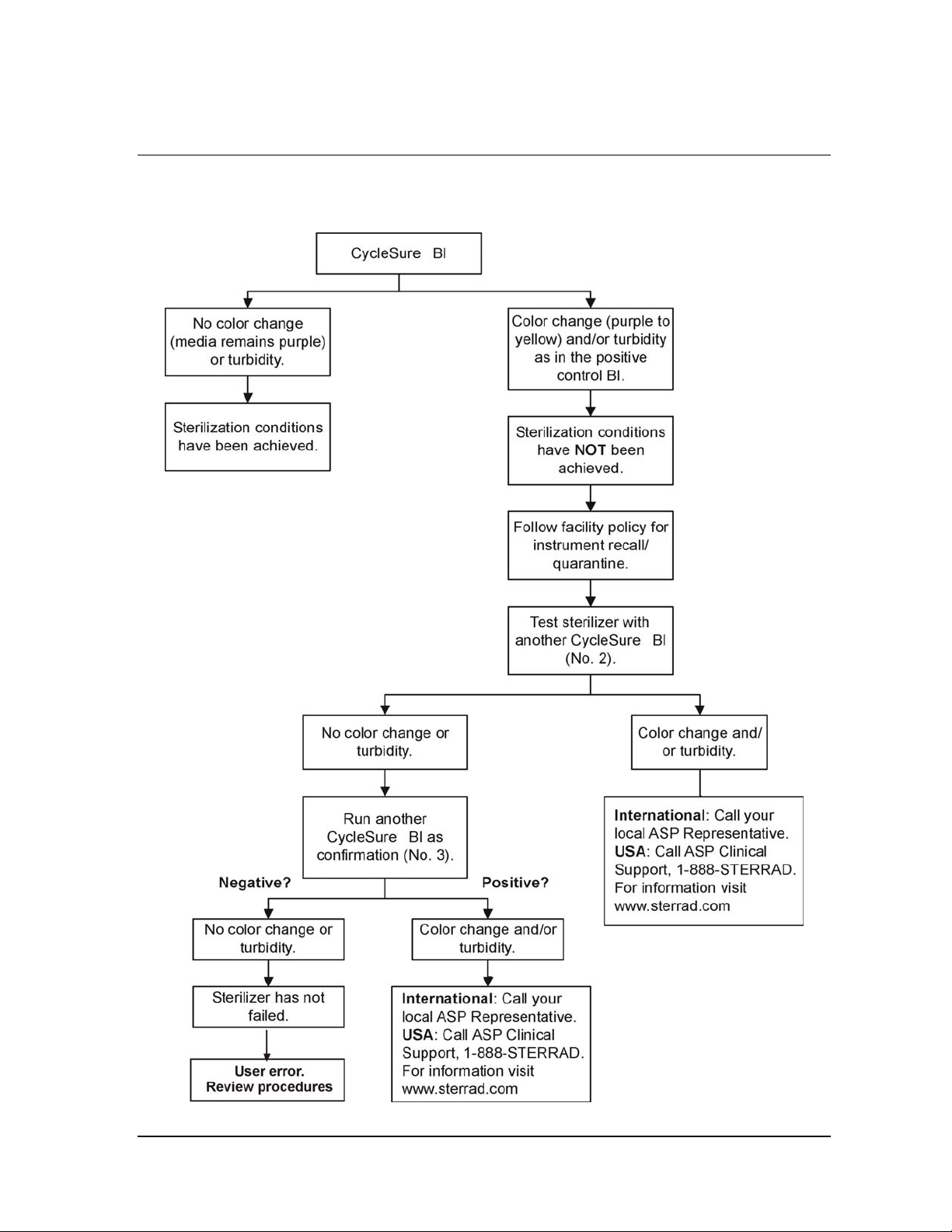
Instructions for Use. Refer to the biological indicator flow chart on the next
page for additional information.
Cycle Completion Flowchart
Printout shows process
complete.
Sterilization
cycle
completed.
Review
printout.
Cancellation
message shows
parameters were
not met.
Chemical indicators
show appropriate color
Are biological indicator
results required by
your facility prior to
YES
Review BI flowchart.
change.
releasing load?
according to your site's
Review Chemical
Indicators from Load
NO
Release the load
policy.
Reject cycle and
resterilize all items.
Chemical indicators
do not show
appropriate color
change.
Reject cycle and
resterilize all items.
46 STERRAD® NX™ User’s Guide
Page 47
Operation 5
STERRAD® CycleSure® Flowchart
STERRAD® NX™ User’s Guide 47
Page 48

Page 49

Access Levels and Supervisor Tasks 6
Chapter 6.
Access Levels and Supervisor Tasks
Overview
Users with supervisor-level access privileges (see below) are permitted to
perform a set of restricted sterilizer functions. These functions are not used
in daily sterilizer operation and some of them are designed to control
access, manage system records, and perform advanced diagnostic functions.
Access Levels
The STERRAD® NX™ Sterilizer can be configured to require that all users
enter a valid operator identification and password before operating the
sterilizer. This access control is enabled through the System Configuration
screen and user identifications, passwords, and access levels are assigned
and maintained through the User Administration screens.
There are three levels of access available. Each is associated with a
different subset of permitted operations.
Operator-level access is designed to permit a user to perform tasks
associated with the daily operation of the sterilizer. These privileges allow a
user to:
♦ Select, start, and cancel a cycle
♦ Enter load item information and cycle notes
♦ Print a cycle history report and view cycle history files
Supervisor-level access includes all of the privileges of Operator-level
access and additionally provides the ability to:
♦ Add, delete, and modify user names, passwords, and access levels
STERRAD® NX™ User’s Guide 49
Page 50
6 Access Levels and Supervisor Tasks
♦ Select, view, and print all sterilizer files
♦ Run diagnostic tests and print reports
♦ Set date and time
♦ Configure sterilizer options
♦ Configure the network connection and upload data to the network
Service-level access is only for use by ASP Service Representatives.
Additional Utilities Menu
The Additional Utilities Menu is available only to users with Supervisor- or
Service-level access privileges. If a user with Operator-level privileges
touches an Additional Utilities button on any screen, the Login screen will
be displayed with the message: “Supervisor- or Service-Level Login
Required.”
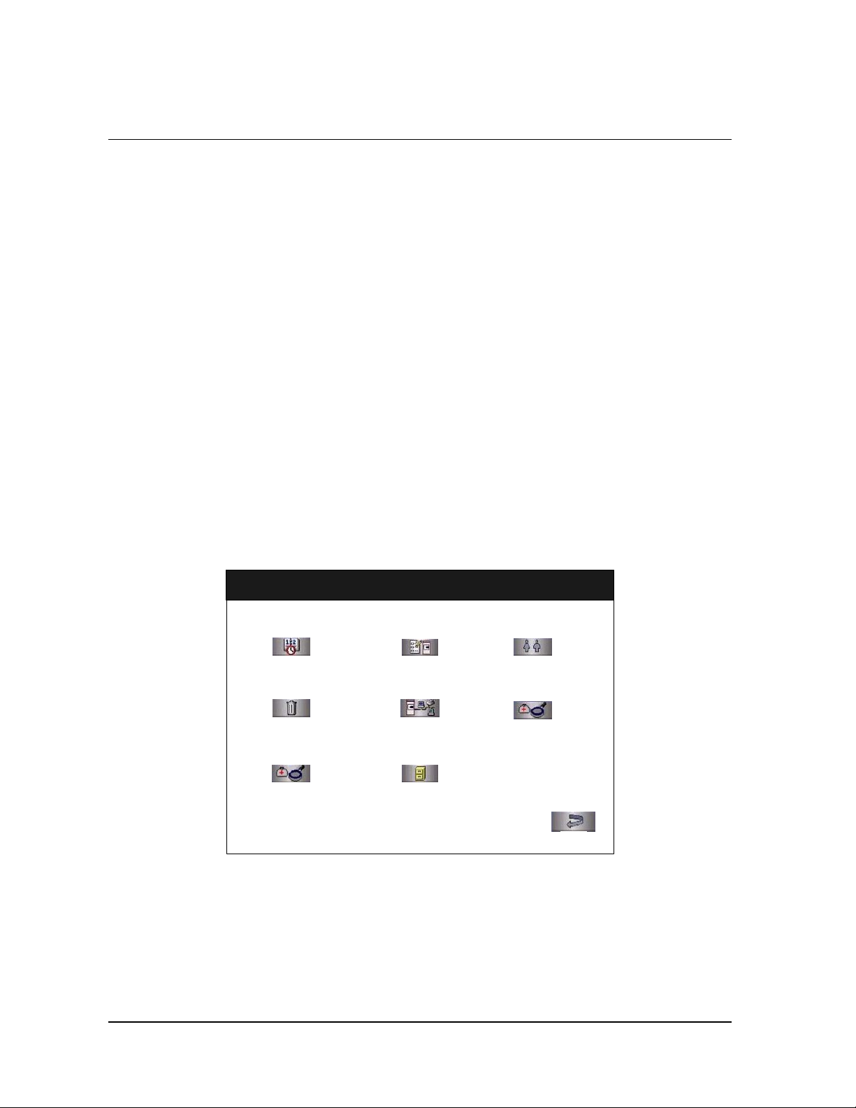
The Additional Utilities Menu allows supervisors to configure the sterilizer
and the network connection, set the date and time, set up and maintain user
privileges, view and print files, perform diagnostic tests, and dispose of
cassettes.
Additional Utilities Menu
Date & Time
Dispose Cassette
Service Functions
System Config
Network
File Management
MM/DD/YY
HH:MM:SS
User Admin
Diagnostics
Back
Figure 24. Additional Utilities Menu.
Figure 65. Additional Utilities Menu
Date & Time allows you to set the date, time, time zone, and formats used
for displaying and printing date and time.
Dispose Cassette moves the currently loaded cassette into the cassette
disposal drawer.
50 STERRAD® NX™ User’s Guide
Page 51
Access Levels and Supervisor Tasks 6
Service Functions are reserved for use by ASP Service Representatives.
System Config allows you to set sterilizer options.
Network allows you to configure the network connection.
File Management allows you to select, display, and print files.
User Admin allows you to add, delete, or modify operator identifications,
passwords, and access levels.
Diagnostics starts a sequence of operator-assisted diagnostic tests and
prints a diagnostic test report.
The Back button returns you to the screen from which you selected
“Additional Utilities.”
Date and Time Settings
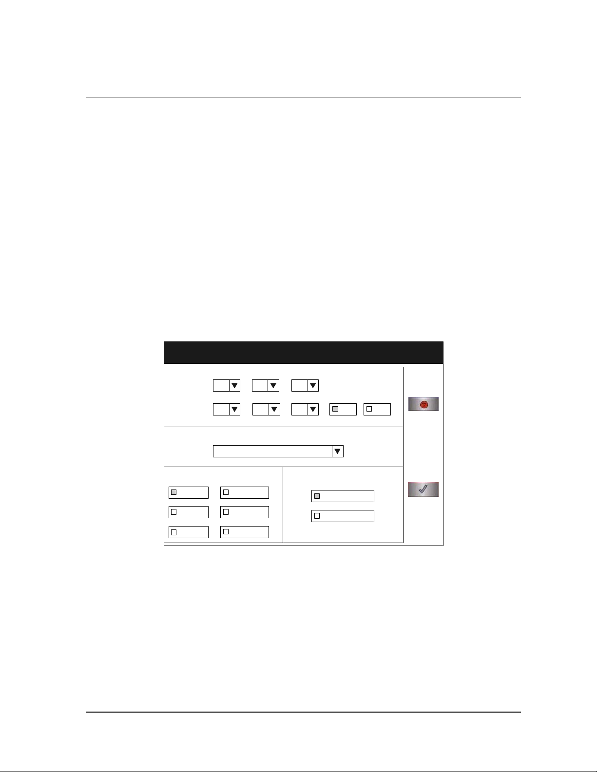
Use the Date and Time Settings screen to set the date and time, and select
the local time zone and display formats.
Set Date
Date and Time Settings
Set Date:
Set Time:
MM/DD/YY
DD/MM/YY
YY/MM/DD
MM DD YY
HH MM SS
Date Format Time Format
MM/DD/YYYY
DD/MM/YYYY
YYYY/MM/DD
Time Zone
MM/DD/YY
HH:MM:SS
AM PM
HH:MM:SS 12 Hour
HH:MM:SS 24 Hour
Cancel
Done
Figure 25. Date and Time Setting
Use the MM box to set the month (01-12), the DD box to set the day (01-
31), and the YY box to set the year.
STERRAD® NX™ User’s Guide 51
Page 52

6 Access Levels and Supervisor Tasks
Set Time
Use the HH box to set the hour (01-12 if 12-hour format is selected, 00-23
if 24-hour format is selected). Use the MM box to set the minute (00-59)
and the SS box to set the second (00-59). If 12-hour format is selected, you
may only select hours 01-12, and you must touch the AM or PM buttons to
indicate the correct time.
Time Zone
Scroll through the selections until your time zone is displayed.
Date Format
Select the desired format for the date. The formats that include “YYYY”
display a four-digit year.
Time Format
Select 12-hour or 24-hour format. If 12-hour format is selected, the AM
and PM buttons on the Set Time line are enabled. If 24-hour format is
selected, the AM and PM buttons are disabled.
Cancel/Done
To cancel the date or time setting, touch the Cancel button. When the date
and time settings are correct, touch the Done button to return to the
Additional Utilities menu.
Dispose Cassette
Touch the Dispose Cassette button when you want to dispose of a cassette
that is currently loaded in the sterilizer. The Dispose Cassette function
moves the cassette from inside the sterilizer to the cassette drawer. Once a
cassette is disposed, the sterilizer will not allow it to be inserted again.
Service Functions
The Service Functions button is reserved for use by ASP Service
Representatives.
52 STERRAD® NX™ User’s Guide
Page 53
Access Levels and Supervisor Tasks 6
System Configuration
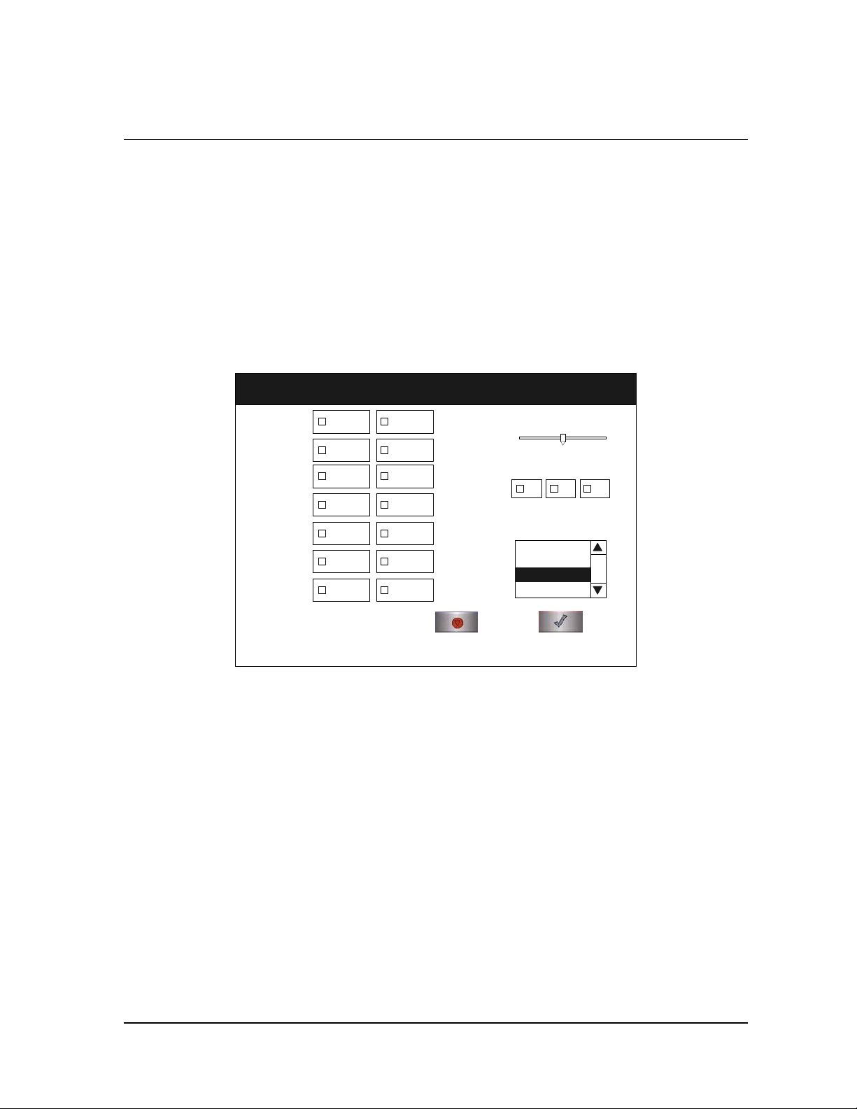
Use the System Configuration screen to set sterilizer options. Selections on
this screen allow you to set the volume of the alarm loudspeaker, the time
interval before the screen backlight is turned off, the language used in
displays and reports, and several access, report, and connection options.
The sterilizer comes configured with factory-set defaults. If you want to
change the default settings, select your preferred settings.
System Configuration
Access Control
Option:
Printout Option:
Vacuum Units:
Load Data
Entry Option:
Load Removal
Option:
Notepad Option:
Network Option:
User
Login
Short
Format
Torr/
mTorr
Enabled
With
Login
Enabled
Enabled
Access Control Option
User Login requires that a user identification and password be entered
before the sterilizer can be loaded and run. This is the factory default
setting.
MM/DD/YY
HH:MM:SS
No User
Login
Long
Format
KPa/
Pa
Disabled
Without
Login
Disabled
Disabled
Alarm
Volume:
min max
Back Light
Conservation
(Minutes):
Language
Selection:
Cancel Done
Figure 26. System Configuration.
Danish
Dutch
English
English
Finnish
30 6015
No User Login allows any person to operate the sterilizer.
Printout Option
Short Format instructs the sterilizer to print only the short report when a
cycle is complete. This is the factory default setting.
Long Format instructs the sterilizer to print only the long report when a
cycle is complete.
STERRAD® NX™ User’s Guide 53
Page 54

6 Access Levels and Supervisor Tasks
Vacuum Units
torr/mtorr expresses vacuum measurements in torr and millitorr.
kPa/Pa expresses vacuum measurements in kilopascals and Pascals. This is
the factory default setting.
Load Data Entry Option
Enabled causes the Enter Load Item Data screen to be displayed after
login. This is the factory default setting.
Disabled skips the Enter Load Item Data screen.
Load Removal Option
With Login requires that a user enter a user identification and password to
open the sterilizer door when a cycle is complete.
Without Login allows any person to open the sterilizer door when a cycle
is complete. This is the factory default setting.
Notepad Option
Network Option
Alarm Volume
Enabled causes the Cycle Notes screen to be displayed after login. This is
the factory default setting.
Disabled skips the Cycle Notes screen.
Enabled allows the sterilizer to be connected to a network.
Disabled disables the network connection. This is the factory default
setting.
Touch the slider to adjust the volume of the alarm loudspeaker. Move the
slider to the far left end to turn the alarm speaker off. The factory default
setting is in the middle of the scale.
54 STERRAD® NX™ User’s Guide
Page 55

Access Levels and Supervisor Tasks 6
Backlight Conservation
The lifetime of the touch screen backlight can be considerably increased if
the sterilizer automatically turns it off when it is not in use.
Select 15, 30, or 60 minutes to set the length of time the backlight remains
on after the screen was last touched. When the selected interval expires, the
backlight is automatically turned off. Touch the screen to turn the backlight
on again. The factory default setting is 15 minutes.
Language Selection
Scroll through the list to select the language used in displays and printed
reports. The factory default setting is English.
Cancel/Done
To cancel system configuration, touch the Cancel button. When the system
configuration settings are correct, touch the Done button on the second
System Configuration screen.
STERRAD® NX™ User’s Guide 55
Page 56
6 Access Levels and Supervisor Tasks
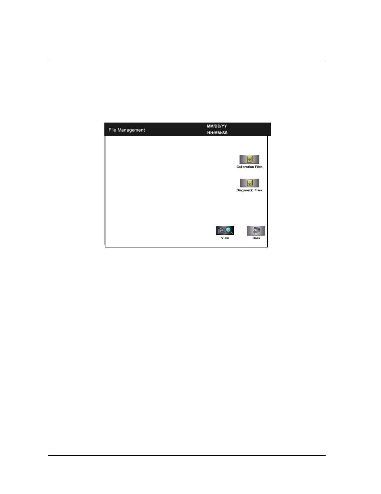
File Management
Use the File Management screen to select and display calibration files or
diagnostic report files.
Calibration Files
Touch the Calibration Files button to display a list of calibration files
created during a sterilizer calibration. Scroll through the list and touch the
file name you wish to view. Touch the View button to display the selected
calibration file. Touch the Back button to return to the Additional Utilities
menu.
Diagnostic Files
Touch the Diagnostic Files button to display a list of reports created by the
Diagnostics function. Scroll through the list and touch the report you wish
to view. Touch the View button to display the selected report. Touch the
Back button to return to the Additional Utilities menu.
Figure 27. File Management.
56 STERRAD® NX™ User’s Guide
Page 57
Access Levels and Supervisor Tasks 6
User Administration
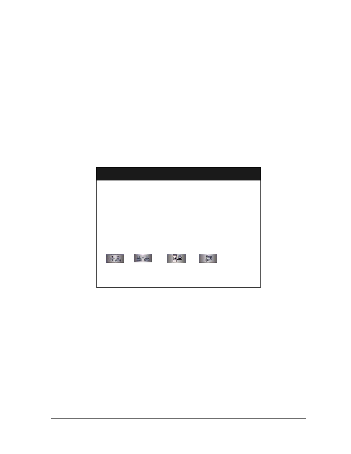
Use the User Administration screen to add, modify, or delete user names,
passwords, and access levels. A button on this screen allows you to upload
user information over your network from a remote host (if configured for
network connection).
4 Note: It is very important that you, as an administrator,
keep track of your password. If you forget or lose
your password, a service call is necessary for you to
regain access to the supervisor area of the system.
User Administration
Add User Modify User Upload User Data Back
MM/DD/YY
HH:MM:SS
Figure 28. User Administration.
Add User displays the Add User screen. On this screen you can set up a
new user’s operator identification, password, and access level.
Modify User displays the Modify User screen. On this screen you can
modify or delete an existing user’s identification, password, and access
level.
Upload User Data causes the sterilizer to receive a complete database file
of user names, passwords, and access levels from a remote host over the
network. (This function does not work if your sterilizer is not configured
for a network connection.)
Back returns you to the Additional Utilities Menu.
STERRAD® NX™ User’s Guide 57
Page 58
6 Access Levels and Supervisor Tasks
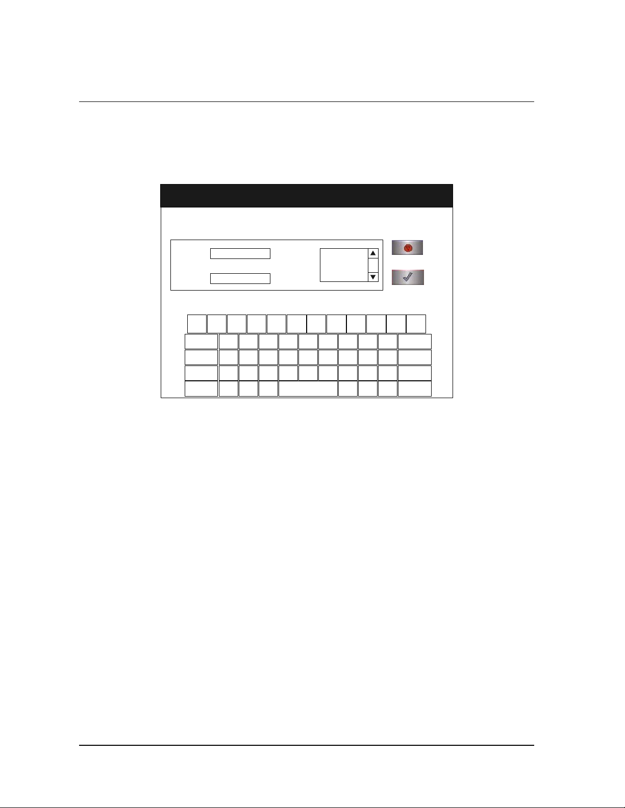
Add User
Use the Add User screen to enter a new user’s identification, password, and
access level.
Add User
{
[
Access Level:
(choose one)
}
]
Operator
Supervisor
Operator:
Password:
!1@2#3$4%5^6&7*8(9)0_-+
Q
W E R T Y U I O P
~
.
CAP LOCK
BACKSP
Z X C V B N M
ALT
MM/DD/YY
HH:MM:SS
<,>
?
|
\
Cancel
Done
=
BACKSP
:
LKJHGFDSA
;
ENTER
.
"
ALT
'
/
Figure 29. Add User.
1. Enter the user’s operator “identification” in the Operator field. The
entry must be alpha-numeric, no more than 10 characters.
4 Note: Operator and Password fields are case-sensitive.
2. Enter the user’s password in the Password field. The entry must be
alpha-numeric, no more than 10 characters.
3. Scroll through the Access Level selections and select an appropriate
access level. You may only choose “Operator” or “Supervisor.”
4. Touch the Cancel button to exit this screen and return to the User
Administration screen.
5. Touch the Done button when you have finished entering information
for a new user.
58 STERRAD® NX™ User’s Guide
Page 59
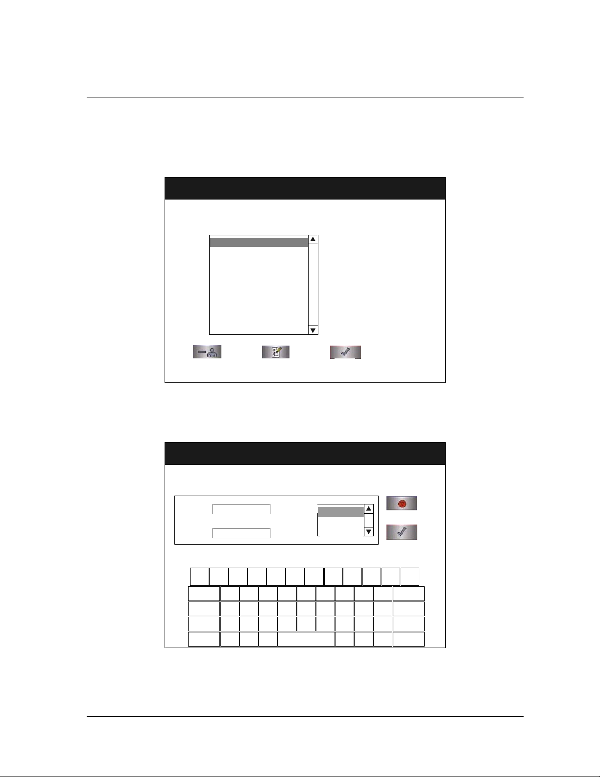
Access Levels and Supervisor Tasks 6
Modify User
Use the Modify User screen to modify an existing user’s identification,
password, and access level.
Modify User
Select User:
MM/DD/YY
HH:MM:SS
Operator "A" name
Operator "B" name
Operator "C" name
Delete User
Edit User
Done
Figure 30. Modify User.
1. Select the user’s name whose information you wish to modify.
2. The selected user’s information is displayed in the Edit User screen.
Edit User
MM/DD/YY
HH:MM:SS
Operator:
Password:
Operator "A"
xxxxxxxxx
!1@2#3$4%5^6&7*8(9)0_-+
Q
W E R T Y U I O P
~
.
CAP LOCK
BACKSP
Z X C V B N M
{
ALT
[
Access Level:
(choose one)
}
]
Operator
Operator
Supervisor
|
\
<,>
?
/
LKJHGFDSA
.
"
'
Cancel
Done
BACKSP
ENTER
ALT
=
:
;
Figure 31. Edit User
♦ To modify the selected user’s information, touch the Edit User
button.
STERRAD® NX™ User’s Guide 59
Page 60
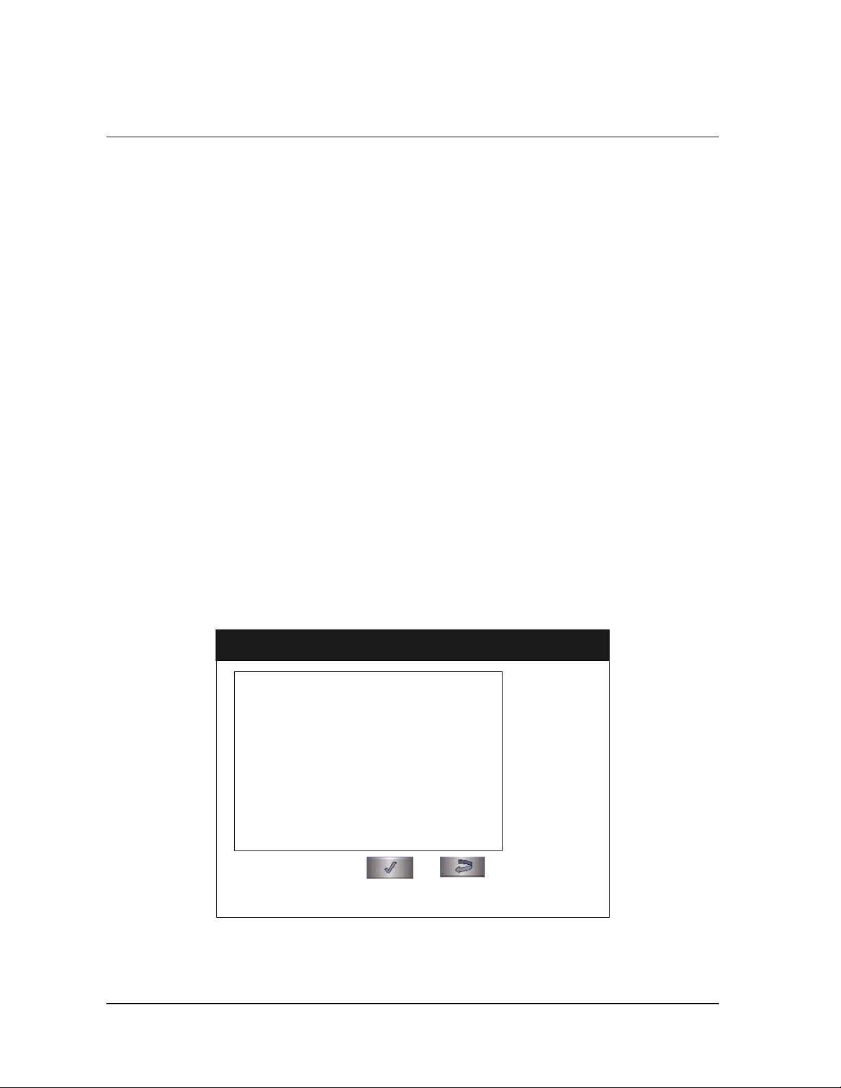
6 Access Levels and Supervisor Tasks
♦ To change the user’s operator name, make changes in the
Operator field.
♦ To change the user’s password, make changes in the Password
field.
♦ To change the user’s access level, select the desired Access Level.
You may only choose “Operator” or “Supervisor.”
3. Touch the Cancel button to exit this screen and return to the Modify
User screen.
4. Touch the Done button when you have finished – the Modify User
screen is displayed.
5. To delete a user (revoke access to the sterilizer), select the user name
and touch the Delete User button.
Upload User Data
If your STERRAD® NX Sterilizer has been configured for network
connectivity, you can also add up to 1000 user identifications by uploading
them to the sterilizer from a remote computer or hospital network.
If you are not familiar with MS-DOS® applications, do not attempt to
upload the user data. Contact your facility’s network administrator for more
information.
When the Upload User Data button is touched, the Upload User Data
screen is displayed.
Upload User Data
Confirm Back
Figure 32. Upload User Data
MM/DD/YY
HH:MM:SS
60 STERRAD® NX™ User’s Guide
Page 61

Access Levels and Supervisor Tasks 6
Steps to Upload a User Database
To upload a list of user identifications and passwords, perform the
following steps:
1. Create an ASCII text file called "users.rec" that contains the user
identifications, passwords, and access levels. Each entry should be
separated by a comma only (no spaces). Example:
USERNAME1,PASSWORD1,ACCESS-LEVEL1
USERNAME2,PASSWORD2,ACCESS-LEVEL2
USERNAME3,PASSWORD3,ACCESS-LEVEL3
where:
♦ USERNAME must be alpha-numeric, no more than 10 characters
♦ PASSWORD must be alpha-numeric, no more than 10 characters
♦ ACCESS-LEVEL must be either 1, 2 (1=Operator, 2 = Supervisor)
2. From a PC running Microsoft
application (emulation of an MS-DOS
®
Windows, open the command prompt
®
shell).
3. Type: cd <path>
where <path> is the pathname to the users.rec file.
4. Determine the sterilizer’s IP address (refer to the Network Settings
screen).
5. Transfer the users.rec file to the sterilizer by typing: TFTP <sterilizer
IP address> PUT users.rec
where <sterilizer IP address> is the address obtained from the Network
Settings screen.
6. On the sterilizer, touch the Upload User Data button. The information
in the file will be displayed with the password concealed by “*”
characters.
®
You will receive an "INVALID STERRAD
NX DATABASE FILE"
message if the password or user name is longer than the permissible
length, you have specified an invalid access level, or you have used an
invalid format.
7. Touch the Confirm button to accept the displayed data, logout the
current user and return to the prior screen.
STERRAD® NX™ User’s Guide 61
Page 62

6 Access Levels and Supervisor Tasks
Diagnostics
Touch the Diagnostics button to start automatic diagnostic testing of the
sterilizer. When started, the diagnostics function prompts you to select one
of two types of tests (either Temperature or Other Tests). If Other Tests is
selected, the sterilizer runs ten operator-assisted tests of the sterilizer
subsystems. You may skip one or more tests in the automatic sequence by
touching the Cancel button when a test begins. This causes the program to
advance to the next test in the sequence.
The ten tests and the sterilizer elements that are tested are listed in the order
in which they occur in Table 6.
Diagnostic Tests
Order Test Name What is tested Average
Time to Run*
1 Power Supply Test High- and low-voltage power supplies and
sensors.
2 Vacuum Test Vacuum pump and pressure sensors. 2 min. 20 sec.
3 Plasma Test Plasma electrical subsystem.
Electrode integrity.
4 Cassette Test Cassette mechanical subsystem.
Barcode reader.
5 Door Test Electric door lock. 20 sec.
6 H2O2 Sensor Test Ultraviolet lamp and detector. 20 sec.
7 Display Test Touch screen calibration and function. 20 sec.
8 Printer Test Printer function. 10 sec.
9 Fan Test Fan speed and function. 10 sec.
10 Sound Test Loudspeaker function and volume. 40 sec.
* Times are approximate. If a failure is detected, the time may be extended.
The ten tests take approximately 13 minutes and 30 seconds to complete.
When the series of tests is complete, the sterilizer creates and stores a
diagnostics file and prints a report. When printing is complete, the
Additional Utilities menu is displayed.
30 sec.
3 min. 40 sec.
5 min.
62 STERRAD® NX™ User’s Guide
Page 63
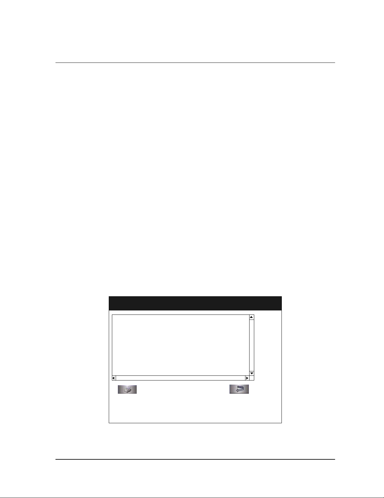
Reports and Files 7
Chapter 7.
Reports and Files
Displayed Reports
Users with Operator-level access can display the System Summary file and
Cycle History files. Users with Supervisor-level access can display the
System Summary file, Cycle History files, as well as Calibration files and
Diagnostic files.
All files that are displayed can be printed by touching the Print button on
the file display screen.
System Summary
The System Summary lists the configuration settings and factory-set
parameters of the sterilizer and the control program.
System Summary
Cycle Number :
Daily Cycle Number :
Logged In :
Access Level :
Language :
Next PM Date :
Software Version :
Print Summary
MM/DD/YY
HH:MM:SS
Back
Figure 33. System Summary
STERRAD® NX™ User’s Guide 63
Page 64

7 Reports and Files
Print Summary prints the contents of the System Summary file. Touch the
scroll bars to scroll through the file. An explanation of the System
Summary file is provided in the following table
Back returns you to the previous screen.
System Summary File
Summary Item Description Comments
Cycle Number Number of cycles since sterilizer
was installed
Daily Cycle Number Number of cycles since start of day
(midnight)
Logged In Name of currently logged-in
operator
Access Level Access level of currently logged-in
operator
Language Current language setting Configurable through System
Next PM Date Date next planned maintenance
service is due
Software Version Version of the sterilizer software Set by factory; modifiable by
Cassette Position Current position of the cassette Determined by sterilizer
Cassette Exp. Date Expiration date of currently
installed cassette
Cassette Barcode Barcode data from currently
installed cassette
Determined by sterilizer
operation
Determined by sterilizer
operation
Determined by operator
Configurable by supervisor
Configuration screen
Set by ASP Service
ASP Service only
operation
Read from barcode on currently
installed cassette
Read from barcode on currently
installed cassette
Access Control Indicates whether user login is
required
Printout Option Indicates print option – short or
long format must be selected
Vacuum Units Scaling used to indicate vacuum:
torr/millitorr or kilopascals/Pascals
Load Data Entry Indicates whether Load Item Data
entry is required
Load Removal Indicates whether users must login
to remove a load
64 STERRAD® NX™ User’s Guide
Configurable through System
Configuration screen
Configurable through System
Configuration screen
Configurable through System
Configuration screen
Configurable through System
Configuration screen
Configurable through System
Configuration screen
Page 65

Reports and Files 7
Summary Item Description Comments
Notepad Indicates whether Cycle Notes
entry is required
Configurable through System
Configuration screen
Alarm Volume Current setting of alarm volume Configurable through System
Configuration screen
Backlight Conservation Current setting of backlight
conservation timer
Configurable through System
Configuration screen
Facility Name Name of your facility Configurable through System
Configuration screen
Department Name Name of your department Configurable through System
Configuration screen
Sterilizer ID A unique identifier of your sterilizer Configurable through System
Configuration screen
Sterilizer Serial # Serial number of your sterilizer Set by ASP Service
Date Format Current setting of date format Configurable through Date and
Time Settings screen
Time Format Current setting of time format Configurable through Date and
Time Settings screen
Time Zone Current setting of time zone Configurable through Date and
Time Settings screen
Remote Hostname* Current setting of remote hostname Configurable through Network
Settings screen
Remote Port Number* Current setting of remote port
number
Sterilizer Host Name* Current setting of sterilizer host
name
Sterilizer IP Address* Current setting of sterilizer IP
address
Name Server IP
Address*
Current setting of name server IP
address
Configurable through Network
Settings screen
Configurable through Network
Settings screen
Configurable through Network
Settings screen
Configurable through Network
Settings screen
Gateway* Current setting of gateway Configurable through Network
Settings screen
Resolver Domain
Name*
Current setting of resolver domain
name
Configurable through Network
Settings screen
Subnet Mask* Current setting of subnet mask Configurable through Network
Settings screen
STERRAD® NX™ User’s Guide 65
Page 66

7 Reports and Files
Summary Item Description Comments
System Board Revision Revision number of system circuit
board
Network Option When enabled, network connection
is supported
Pressure Zeroing Current setting for the pressure
zeroing procedure
Pressure Zeroing Time
Interval
Pressure Zeroing Time
of day
Pressure Zeroing
Printout
IMS† Hardware Current IMS hardware
IMS Mode Current setting of the IMS option Set by ASP Service
IMS Printout Indicates whether printout is
Current setting of the time interval
of when to start the pressure zeroing
procedure
Current setting of the time of day to
start the pressure zeroing procedure
Indicates whether printout is
required
configuration of the sterilizer
required
* Not applicable if Network Option is disabled.
† Independent Monitoring System.
Determined by sterilizer
operation
Configurable through System
Configuration screen
Set by ASP Service
Set by ASP Service
Configurable through System
Configuration screen
Configurable through System
Configuration screen
Set by ASP Service
Configurable through System
Configuration screen
66 STERRAD® NX™ User’s Guide
Page 67
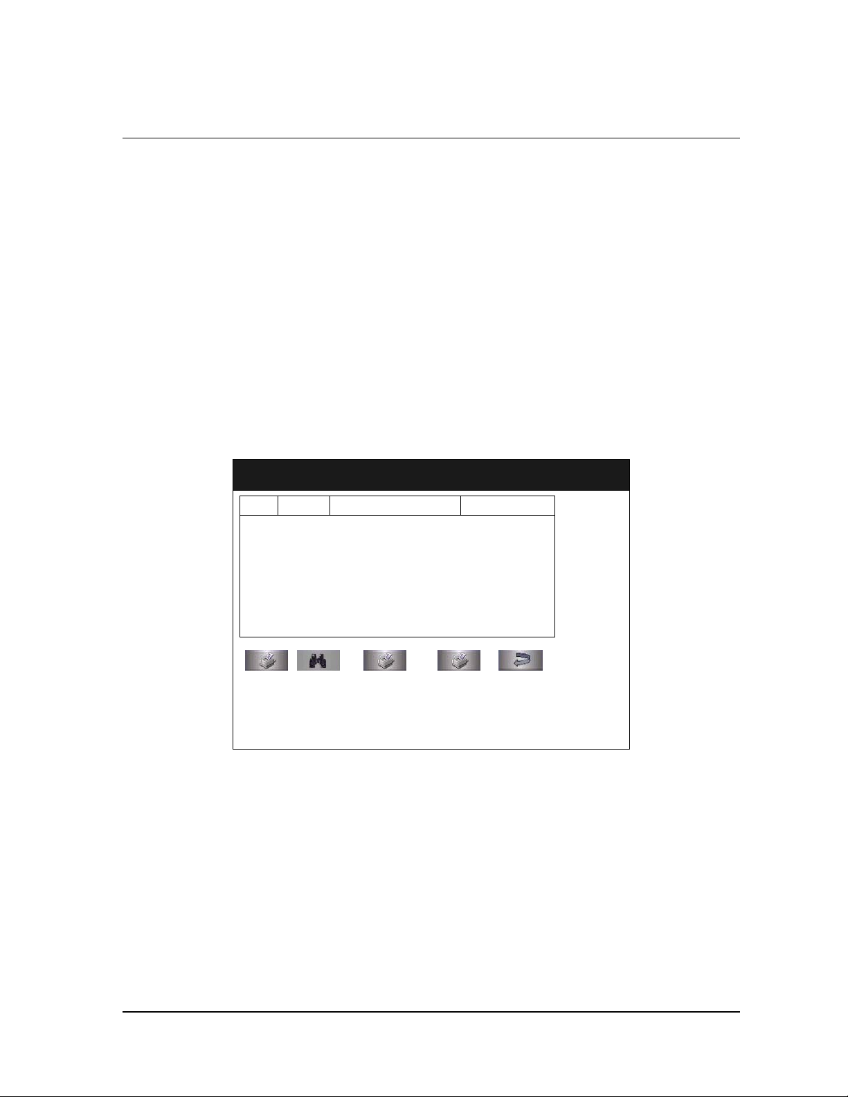
Reports and Files 7
Cycle History
Cycle history data is stored in the sterilizer’s memory. The memory holds
data from the last 50 cycles. After 50 cycles are completed, the oldest cycle
history record is overwritten with new data from the 51
sterilizer is configured with the optional network connection, cycle history
data can be periodically uploaded to a host computer and preserved
permanently if desired.
When you touch the View Cycle History button on any screen where the
button appears, the program displays the Select Cycle History screen. The
list box shows the cycle number, status, completion date and time, and
reason for cancellation (if applicable) for all cycle history records currently
in the sterilizer’s memory.
Touch the scroll bars to scroll through the list. Touch the line you wish to
select.
st
cycle. If your
Select Cycle History File
Cycle
Number
Print List
Status
View Cycle Print Cycle(Short) Print Cycle(Long) Back
Figure 34. Select Cycle History File.
Completion
Date Time
MM/DD/YY
HH:MM:SS
Reason
Print List prints a list of all cycle history files stored in the sterilizer.
View Cycle displays the selected Cycle History file on the screen.
Print Cycle (Short) prints a short-format report of the selected cycle
history file.
Print Cycle (Long) prints a long-format report of the selected cycle history
file.
Back returns you to the previous screen.
STERRAD® NX™ User’s Guide 67
Page 68

7 Reports and Files
Printed Reports
Every time a cycle is completed, a cycle completion report is printed.
Depending upon how your sterilizer has been configured, the report will
either be a short-format report or a long-format report. Both reports extract
data from the cycle history record created by the cycle. The short-format
report indicates the cycle status (Passed or Failed), date, time, operator and
load information. The long-format report includes all of the data in the
short report plus detailed information about each stage of the sterilization
cycle.
Short Report
The short-format report lists identifying information about the cycle, shows
the cycle status, lists the date and duration of the cycle, and shows operator
and load identifying information. The short-format report is useful for
recordkeeping purposes and providing traceability of sterilized loads. An
example of a short-format report is illustrated in the following figure.
Software Version: xxx
Facility Name: xxxxxx
Department Name:xxxxxx
Sterilizer ID: xxx
Serial #: xxxxxxxx
Cycle #: xxxx
Daily Cycle #: xx
Operator: Operator A
Load Items: xxxxxxx
Cycle Notes: xxxxxxx
Selected Cycle: SHORT-CYCLE
Cycle Start Time: MM/DD/YY
HH:MM:SS
Cycle End Time: MM/DD/YY
HH:MM:SS
Elapsed Time: HH:MM:SS
CYCLE STATUS: PASSED
PROCESS COMPLETE
Validated by:_________________
Cassette Bar Code: xxxxxxxxx
NUMBER OF CYCLES AVAILABLE=X
Figure 35. Short Formal Report
68 STERRAD® NX™ User’s Guide
Page 69

Reports and Files 7
Long Report
The long-format report lists detailed information about the cycle, shows the
cycle status, lists the date and duration of the cycle, shows operator and
load identifying information, and provides detailed data about the operation
of the sterilizer, including temperatures, pressures, plasma measurements,
and sterilant concentrations throughout the cycle. The long-format report is
useful for detailed cycle quality control and contains valuable diagnostics
information for ASP Service Representatives.
An example of a long-format report is illustrated in the following three
figures.
STERRAD® NX™ User’s Guide 69
Page 70

7 Reports and Files
(
Software Version: xxx
Facility Name: xxxxxx
Department Name: xxxxxx
Sterilizer ID: xxx
Serial #: xxxxxxxx
Cycle #: xxxx
Daily Cycle #: xx
Operator: Operator A
Load Items: xxxxxxxxxx
Cycle Notes: xxxxxxxxxx
Selected Cycle: STNX-SHORT-CYCLE
Cycle Start Time: MM/DD/YY
HH:MM:SS
Cycle End Time: MM/DD/YY
HH:MM:SS
Elapsed Time: HH:MM:SS
Cycle Status: Passed
(Warm Up Start)
Start Time End Time Stage Time
XX:XX:XX XX:XX:XX XX:XX:XX
Sensor Max Min
----------- ------- ------Pressure: >30Torr >30Torr
Chamber Temp: xx.xC xx.xC
Door Temp: xx.xC xx.xC
Vaporizer Temp: xx.xC xx.xC
Condenser Temp: xx.xC xx.xC
(Injection 1)
Delivery)
Start Time End Time Stage Time
XX:XX:XX XX:XX:XX XX:XX:XX
Sensor Max Min
----------- ------- ------Pressure: xxxTorr xxxTorr
Chamber Temp: xx.xC xx.xC
Door Temp: xx.xC xx.xC
Vaporizer Temp: xx.xC xx.xC
Condenser Temp: xx.xC xx. xC
H2O2 Monitor(mg/l): x.x x.x
(Vaporization Pumpdown 1)
Start Time End Time Stage Time
XX:XX:XX XX:XX:XX XX:XX:XX
Sensor Max Min
----------- ------- -------
Figure 36. Long Format Report
Pressure: xxxTorr xxxTorr
Chamber Temp: xx.xC xx.xC
Door Temp: xx.xC xx.xC
Vaporizer Temp: xx.xC xx.xC
Condenser Temp: xx.xC xx.xC
(Chamber Pumpdown 1)
Start Time End Time Stage Time
XX:XX:XX XX:XX:XX XX:XX:XX
Sensor Max Min
----------- ------- ------Pressure: xxxTorr xxxmTorr
Chamber Temp: xx.xC xx.xC
Door Temp: xx.xC xx.xC
Vaporizer Temp: xx.xC xx.xC
Condenser Temp: xx.xC xx.xC
(Transfer 1)
Start Time End Time Stage Time
XX:XX:XX XX:XX:XX XX:XX:XX
Sensor Max Min
----------- ------- ------Pressure: xxxmTorr xxxmTorr
Chamber Temp: xx.xC xx.xC
Door Temp: xx.xC xx.xC
Vaporizer Temp: xx.xC xx.xC
Condenser Temp: xx.xC xx.xC
(Pressure Check 1)
Start Time End Time Stage Time
XX:XX:XX XX:XX:XX XX:XX:XX
Sensor Max Min
----------- ------- ------Pressure: xxxTorr xxxmTorr
Chamber Temp: xx.xC xx.xC
Door Temp: xx.xC xx.xC
Vaporizer Temp: xx.xC xx.xC
Condenser Temp: xx.xC xx.xC
(Diffusion 1)
Start Time End Time Stage Time
XX:XX:XX XX:XX:XX XX:XX:XX
Sensor Max Min
----------- ------- ------Pressure: xxxTorr xxxTorr
Chamber Temp: xx.xC xx.xC
Door Temp: xx.xC xx.xC
Vaporizer Temp: xx.xC xx.xC
Condenser Temp: xx.xC xx.xC
70 STERRAD® NX™ User’s Guide
Page 71

Reports and Files 7
y)
(Plasma Pumpdown 1)
Start Time End Time Stage Time
XX:XX:XX XX:XX:XX XX:XX:XX
Sensor Max Min
----------- ------- ------Pressure: >30Torr >30Torr
Chamber Temp: xx.xC xx.xC
Door Temp: xx.xC xx.xC
Vaporizer Temp: xx.xC xx.xC
Condenser Temp: xx.xC xx.xC
Max. Delivered Power: xxx Watts
Min. Delivered Power: x Watts
Plasma Time: x:xx
(Plasma 1)
Start Time End Time Stage Time
XX:XX:XX XX:XX:XX XX:XX:XX
Sensor Max Min
----------- ------- ------Pressure: xxxTorr xxxTorr
Chamber Temp: xx.xC xx.xC
Door Temp: xx.xC xx.xC
Vaporizer Temp: xx.xC xx.xC
Condenser Temp: xx .xC x x.xC
Max. Delivered Power: xxx Watts
Min. Delivered Power: x Watts
Plasma Time: x:xx
(Vent 1)
Start Time End Time Stage Time
XX:XX:XX XX:XX:XX XX:XX:XX
Sensor Max Min
----------- ------- ------Pressure: xxxmTorr xxxmTorr
Chamber Temp: xx.xC xx.xC
Door Temp: xx.xC xx.xC
Vaporizer Temp: xx.xC xx.xC
Condenser Temp:xx.xC xx.xC
(Injection 2)
Deliver
Start Time End Time Stage Time
XX:XX:XX XX:XX:XX XX:XX:XX
Sensor Max Min
----------- ------- ------Pressure: xxxTorr xxxTorr
Chamber Temp: xx.xC xx.xC
Door Temp: xx.xC xx.xC
Vaporizer Temp: xx.xC xx.xC
Condenser Temp: xx.xC xx.xC
H2O2 Monitoring(mg/l): x.x x.x
(Vaporization Pumpdown 2)
Start Time End Time Stage Time
XX:XX:XX XX:XX:XX XX:XX:XX
Sensor Max Min
----------- ------- ------Pressure: xxxTorr xxxTorr
Chamber Temp: xx.xC xx.xC
Door Temp: xx.xC xx.xC
Vaporizer Temp: xx.xC xx.xC
Condenser Temp: xx.xC xx.xC
(Chamber Pumpdown 2)
Start Time End Time Stage Time
XX:XX:XX XX:XX:XX XX:XX:XX
Sensor Max Min
----------- ------- ------Pressure: xxxTorr xxxmTorr
Chamber Temp: xx.xC xx.xC
Door Temp: xx.xC xx.xC
Vaporizer Temp: xx.xC xx.xC
Condenser Temp: xx.xC xx.xC
(Transfer 2)
Start Time End Time Stage Time
XX:XX:XX XX:XX:XX XX:XX:XX
Sensor Max Min
----------- ------- ------Pressure: xxxmTorr xxxmTorr
Chamber Temp: xx.xC xx.xC
Door Temp: xx.xC xx.xC
Vaporizer Temp: xx.xC xx.xC
Condenser Temp:xx.xC xx.xC
(Pressure Check 2)
Start Time End Time Stage Time
XX:XX:XX XX:XX:XX XX:XX:XX
Sensor Max Min
----------- ------- ------Pressure: xxxTorr xxxTorr
Chamber Temp: xx.xC xx.xC
Door Temp: xx.xC xx.xC
Vaporizer Temp: xx.xC xx.xC
Condenser Temp:xx.xC xx.xC
Figure 37. Long Format Report (continued).
STERRAD® NX™ User’s Guide 71
Page 72

7 Reports and Files
(Diffusion 2)
Start Time End Time Stage Time
XX:XX:XX XX:XX:XX XX:XX:XX
Sensor Max Min
----------- ------- ------Pressure: xxxTorr xxxTorr
Chamber Temp: xx.xC xx.xC
Door Temp: xx.xC xx.xC
Vaporizer Temp: xx.xC xx.xC
Condenser Temp:xx.xC xx.xC
(Plasma Pumpdown 2)
Start Time End Time Stage Time
XX:XX:XX XX:XX:XX XX:XX:XX
Sensor Max Min
----------- ------- ------Pressure: xxxTorr xxxTorr
Chamber Temp: xx.xC xx.xC
Door Temp: xx.xC xx.xC
Vaporizer Temp: xx.xC xx.xC
Condenser Temp:xx.xC xx.xC
Process Complete
Validated by: _____________________
Cassette Bar Code: XXXXXXXXXX
Number of Cycles Available=X
t
(Plasma 2)
Start Time End Time Stage Time
XX:XX:XX XX:XX:XX XX:XX:XX
Sensor Max Min
----------- ------- ------Pressure: xxxmTorr xxxmTorr
Chamber Temp: xx.xC xx.xC
Door Temp: xx.xC xx.xC
Vaporizer Temp: xx.xC xx.xC
Condenser Temp:xx.xC xx.xC
Max. Delivered Power: xxx Watts
Min. Delivered Power: x Watts
Plasma Time: x:xx
(Final Vent)
Start Time End Time Stage Time
XX:XX:XX XX:XX:XX XX:XX:XX
Sensor Max Min
----------- ------- ------Pressure: xxxTorr xxxmTorr
Chamber Temp: xx.xC xx.xC
Door Temp: xx.xC xx.xC
Vaporizer Temp: xx.xC xx.xC
Condenser Temp:xx.xC xx.xC
Max. Delivered Power: xxx Watts
Min. Delivered Power: x Watts
Plasma Time: x:xx
Figure 38. Long Format Report (continued).
72 STERRAD® NX™ User’s Guide
Page 73
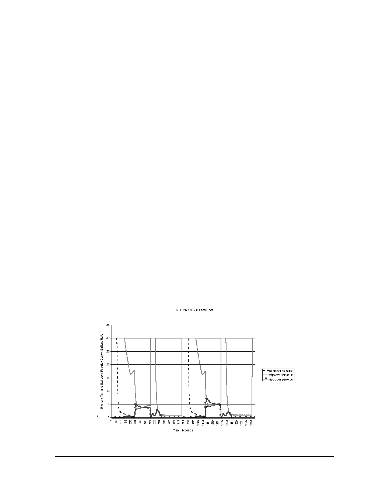
Reports and Files 7
Files
The STERRAD® NX™ Sterilizer creates, stores, displays, prints, and can
upload over a network several files of sterilizer and cycle-related data.
These files include cycle history files. Each file is explained in the
following sections.
Cycle History Files
Cycle history files contain very detailed information about each
sterilization cycle. The files include identifying information about the
operator, load, time, date, cycle duration information, stage-by-stage data
from the sensors and controls, and related technical items. Information is
extracted from the cycle history file to produce the short-format report and
the long-format report. The cycle history file contains information that is
vital to a facility’s recordkeeping and traceability procedures. The
sterilizer’s memory holds data from the last 50 cycles.
Cycle history files can be viewed and printed by users with Operator-level
access.
The following figure features an example of a Cycle Profile Graph that may
be viewed for each cycle run by the sterilizer. This graph depicts plots of
the chamber pressure, vaporizer pressure and hydrogen peroxide pressure.
From the Select Cycle History File screen, pressing the View Cycle button
will display the Cycle History screen. This screen shows the cycle data for
the sterilization cycle. The Cycle History screen also contains a Cycle
History Graph button that will display the Cycle Graph.
Figure 39. Cycle Profile - Standard Cycle.
STERRAD® NX™ User’s Guide 73
Page 74

7 Reports and Files
Calibration Files
Calibration files are generated every time the sterilizer is recalibrated. The
files contain details about the inputs and outputs from calibrated sensors.
This information ensures that the sterilizer is operating within its
calibration limits and is useful to ASP Service Representatives when
performing maintenance or service.
Calibration files can only be viewed and printed by users with Supervisorlevel access.
Examples of a temperature calibration report, a thermistor resistance
adjustment report, and a hydrogen peroxide monitor calibration report are
illustrated in the following three figures.
74 STERRAD® NX™ User’s Guide
Page 75

Reports and Files 7
Temp Calibration/Verification Report
. . . . . . . . . . . . . . . . . . . . .
File Name: /xxxxxxxxxxxxx
CH1 Heater R: xxxxxxxxxxxx
CH1 Heater A: xxxxxxxxxxxx
CH1 Heater B: xxxxxxxxxxxx
CH1 Heater C: xxxxxxxxxxxx
50C Verify Point(C): xx.x
70C Verify Point(C): xx.x
CH1 Htr Status: XXXXXX
Last Verified: MM/DD/YY
HH:MM
CH2 Heater R: xxxxxxxxxxxx
CH2 Heater A: xxxxxxxxxxxx
CH2 Heater B: xxxxxxxxxxxx
CH2 Heater C: xxxxxxxxxxxx
50C Verify Point(C): xx.x
70C Verify Point(C): xx.x
CH2 Htr Status: XXXXXX
Last Verified: MM/DD/YY
HH:MM
Door Heater R: xxxxxxxxxxxx
Door Heater A: xxxxxxxxxxxx
Door Heater B: xxxxxxxxxxxx
Door Heater C: xxxxxxxxxxxx
50C Verify Point(C): xx.x
70C Verify Point(C): xx.x
Door Htr Status: XXXXXX
Last Verified: MM/DD/YY
HH:MM
Cond Heater R: xxxxxxxxxxxx
Cond Heater A: xxxxxxxxxxxx
Cond Heater B: xxxxxxxxxxxx
Cond Heater C: xxxxxxxxxxxx
50C Verify Point(C): xx.x
70C Verify Point(C): xx.x
Cond Htr Status: XXXXXX
Last Verified: MM/DD/YY
HH:MM
Vap Heater R: xxxxxxxxxxxx
Vap Heater A: xxxxxxxxxxxx
Vap Heater B: xxxxxxxxxxxx
Vap Heater C: xxxxxxxxxxxx
50C Verify Point(C): xx.x
70C Verify Point(C): xx.x
Vap Htr Status: XXXXXX
Last Verified: MM/DD/YY
HH:MM
Figure 40. Temperature Calibration Report Example.
STERRAD® NX™ User’s Guide 75
Page 76

7 Reports and Files
Thermistor Resistance
Adjustment Report
. . . . . . . . . . . . . . . . . . . . . . . . . . . . . . . . .
File Name: temprxxxxxxxx
Last Verified: MM/DD/YY
HH:MM
Door:
Rprecision: xxxxx Ohm
Rmeasured: xxxxx Ohm
Rdiff: xxxxx Ohm
Status: Passed
Chamber 1:
Rprecision: xxxxx Ohm
Rmeasured: xxxxx Ohm
Rdiff: xxxxx Ohm
Status: Passed
Chamber 2:
Rprecision: xxxxx Ohm
Rmeasured: xxxxx Ohm
Rdiff: xxxxx Ohm
Status: Passed
Vaporizer:
Rprecision: xxxxx Ohm
Rmeasured: xxxxx Ohm
Rdiff: xxxxx Ohm
Status: Passed
Condenser:
Rprecision: xxxxx Ohm
Rmeasured: xxxxx Ohm
Rdiff: xxxxx Ohm
Status: Passed
Figure 41. Thermistor Resistance Adjustment Report Example.
76 STERRAD® NX™ User’s Guide
Page 77

Reports and Files 7
H2O2 Monitor Calibration
. . . . . . . . . . . . . . . . . . . . . . . . . . . . . . . . .
H2O2 Monitor A: x.xxexx
H2O2 Monitor B: x.xxexx
H2O2 Monitor C: x.xxexx
H2O2 Monitor Passed
Last Verified: MM/DD/YY
HH:MM:SS
Figure 42. Hydrogen Peroxide Monitor Calibration Report Example.
Diagnostic Files
Diagnostic files are created by the diagnostics tests that are available only
to users with Supervisor-level access. The files contain details about the
tests and the outcomes (Passed or Failed) of each. This information is
useful to ASP Service Representatives when performing maintenance or
service.
Diagnostic files can only be viewed and printed by users with Supervisorlevel access.
An example of a Diagnostic file is illustrated in the following figure.
STERRAD® NX™ User’s Guide 77
Page 78

7 Reports and Files
DIAGNOSTICS REPORT
. . . . . . . . . . . . . .
File Name: /xxxxxx
Power Supply Test
3.3 Volts Power Supply: x.x
5 Volts Power Supply: x.x
12 Volts Power Supply: xx.x
15 Volts Power Supply: xx.x
24 Volts Power Supply: xx.x
POWER SUPPLY TEST PASSED/FAILED
Time Stamp: MM/DD/YY
HH:MM:SS
Pressure Test
PRESSURE TEST PASSED/FAILED
Time Stamp: MM/DD/YY
HH:MM:SS
Plasma Test
PLASMA TEST PASSED/FAILED
Time Stamp: MM/DD/YY
HH:MM:SS
Cassette Test
CASSETTE TEST PASSED/FAILED
Time Stamp: MM/DD/YY
HH:MM:SS
H2O2 Sensor Test
H2O2 SENSOR TEST PASSED/FAILED
Time Stamp: MM/DD/YY
HH:MM:SS
Fan Test
FAN TEST PASSED/FAILED
Time Stamp: MM/DD/YY
HH:MM:SS
Sound Test
SOUND TEST PASSED/FAILED
Time Stamp: MM/DD/YY
HH:MM:SS
Character Set
. . . . . . . . . . . . . .
ABCDEFGHIJKLMNOPQRSTUVWXZY
a b c d e f g h i j k l m n o p q r s t u v w x yz
! # $ % & ' ( ) * + , _ . / : ; < > ? @ [ ] ^ _ { | }
0123456789
Display Test
DISPLAY TEST PASSED/FAILED
Time Stamp: MM/DD/YY
HH:MM:SS
Temperature Test
Door Rate: x.x c/min
Chamber Low Rate: x.x c/min
Chamber High Rate: x.x c/min
Vaporizer Rate: x.x c/min
Condenser Heat Rate: x.x c/min
Condenser Cool Rate: x.x c/min
Display Test
DISPLAY TEST PASSED/FAILED
Time Stamp: MM/DD/YY
HH:MM:SS
Printer Test
PRINTER TEST PASSED/FAILED
Time Stamp: MM/DD/YY
HH:MM:SS
Figure 43. Diagnostic File Example.
78 STERRAD® NX™ User’s Guide
Page 79

Maintenance 8
Chapter 8.
Maintenance
4 Note: Repairs and adjustments should only be attempted by
experienced technicians who are fully trained to
maintain and repair the STERRAD
Use of unauthorized parts for maintenance or repair
could cause personal injury, result in costly damage,
or sterilizer malfunction and voids the warranty.
®
NX ™ Sterilizer.
Automatic Maintenance
Some maintenance procedures are performed automatically by the sterilizer
software. The user does not have to perform any task to start an automatic
maintenance procedure. There are two automatic maintenance procedures
controlled by the software, they are:
♦ Pressure Zeroing
♦ Automatic Lamp Adjustment
Pressure Zeroing
Periodically, the sterilizer will need to adjust the pressure transducers to
ensure that they are operating within the required parameters.
When the operator presses the Touch Screen to Start screen, and if the
sterilizer is within two days of its automatic pressure zeroing function, a
“Pressure Zeroing Recommended” warning message will be displayed,
notifying the operator that the Pressure Zeroing function should be run. If a
Pressure Zeroing procedure has not been performed by the operator within
the required time interval, a “Pressure Zeroing Required” warning message
will be displayed on the System Ready screen. If this occurs, the operator
will be unable to start a cycle. A Supervisor will be required to successfully
perform the Pressure Zeroing procedure.
STERRAD® NX™ User’s Guide 79
Page 80

8 Maintenance
Pressure Zeroing Report
. . . . . . . . . . . . . . . . . . . . . . . . . . . . . . . . .
Time Stamp MM/DD/YY HH:MM
Result: [PASS/FAIL]
Chamber Offset: xx mTorr
Vaporizer Offset: xx mTorr
Chamber 1 Temperature: xx.x C
Chamber 2 Temperature: xx.x C
Vaporizer Temperature: xx.x C
Door Temperature: xx.x C
Condenser Temperature: xx.x C
Chamber Pressure: xx mTorr
Vaporizer Pressure: xx mTorr
Reference Pressure: xx mTorr
Figure 44. Pressure Zeroing Report.
Automatic Lamp Adjustment
When the sterilizer shows the System Ready screen, the message “Auto
Adjustment in Progress” will be displayed while the sterilizer adjusts the
intensity of the UV lamp. This function can take between 5 and 40 minutes
to complete. The automatic adjustment will take place if the lamp voltage is
below a preset limit.
80 STERRAD® NX™ User’s Guide
Page 81

Maintenance 8
Manual Maintenance
The following maintenance procedures are performed by the user.:
♦ Disposing of cassettes.
♦ Inserting a new cassette disposal box.
♦ Replacing the printer paper roll.
♦ Cleaning the sterilizer exterior.
♦ Cleaning the hydrogen peroxide monitor detector lens.
♦ Replacing the air filter.
♦ Replacing the PCMCIA card (if desired).
♦ Disposing of a sterilizer.
These tasks are performed when needed. The printer paper is replaced when
the roll is empty. The sterilizer exterior should be cleaned only when
necessary. This chapter provides step-by-step instructions on how to
perform these maintenance tasks. Inserting a cassette box follows the
disposal section.
Disposing of Cassettes
When a cassette is empty the sterilizer automatically moves it to the
cassette disposal box in the collection drawer. The screen displays a
message instructing you which actions to take next. When the cassette
disposal box contains three cassettes, it is full, and you must dispose of the
full cassette disposal box. For safety reasons, you must use the cassette
disposal box to dispose of cassettes. Never reuse a cassette disposal box.
Once a cassette disposal box has been removed from the drawer, a new
cassette disposal box must be assembled and inserted in the drawer.
Removing a Cassette Disposal Box
CAUTION! HYDROGEN PEROXIDE MAY BE PRESENT.
Wear latex, PVC (vinyl), or nitrile gloves. This will protect you from contact
with any residual hydrogen peroxide that may be present in the cassettes.
1. Pull open the cassette drawer.
2. Lift the disposal box of used cassettes out of the drawer.
STERRAD® NX™ User’s Guide 81
Page 82
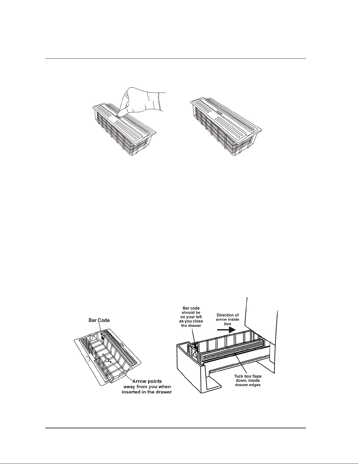
8 Maintenance
3. Fold the flaps over the top of the box. Push the tab of one flap into the
slot of the other flap.
Figure 46. Push Tab Into Slots Figure 47. Closed Box Can Now Be Discarded
4. The closed box is now ready for disposal. It can be discarded as
directed by your facility’s disposal procedures.
5. Install a new cassette disposal box in the cassette drawer.
Inserting a New Cassette Disposal Box
After disposing of a used cassette disposal box, following your facility’s
policy, a new box must be assembled and inserted into the cassette
collection drawer.
1. Remove a new, unused cassette disposal box from the packaging.
2. Place the box inside the drawer making sure the arrow on the bottom of
the box faces away from you.
Figure 45. Correct Placement of Cassette Box in Drawer. Notice the Direction of the Arrow in the Box.
3. Tuck the flaps on the box inside the drawer edges. Close the drawer.
82 STERRAD® NX™ User’s Guide
Page 83
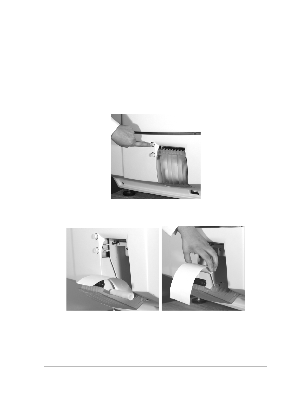
Maintenance 8
Replacing Printer Paper
When the printer paper roll is empty, the sterilizer displays a message
“Printer is out of paper. Please load a new roll.”
1. Open the printer by pressing the top button. The printer door drops
forward.
Figure 46. Open the Printer Door.
2. The empty paper roll rests on the bottom of the printer door. Remove
the empty roll.
Figure 47. Remove the Empty Paper Roll.
STERRAD® NX™ User’s Guide 83
Page 84
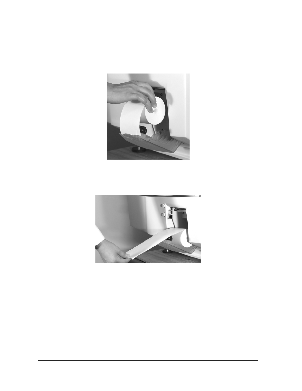
8 Maintenance
3. Insert a new paper roll as shown in the following figure. The paper
should feed from the top of the roll.
Figure 48. Insert a New Paper Roll.
4. Pull a short length of paper over the top of the printer door.
5. Align the paper so that it fits between the two paper guides on the top
of the printer door.
Figure 49. and Pull the Paper Over the Top of the Door and Align the Paper Between the Guides.
84 STERRAD® NX™ User’s Guide
Page 85
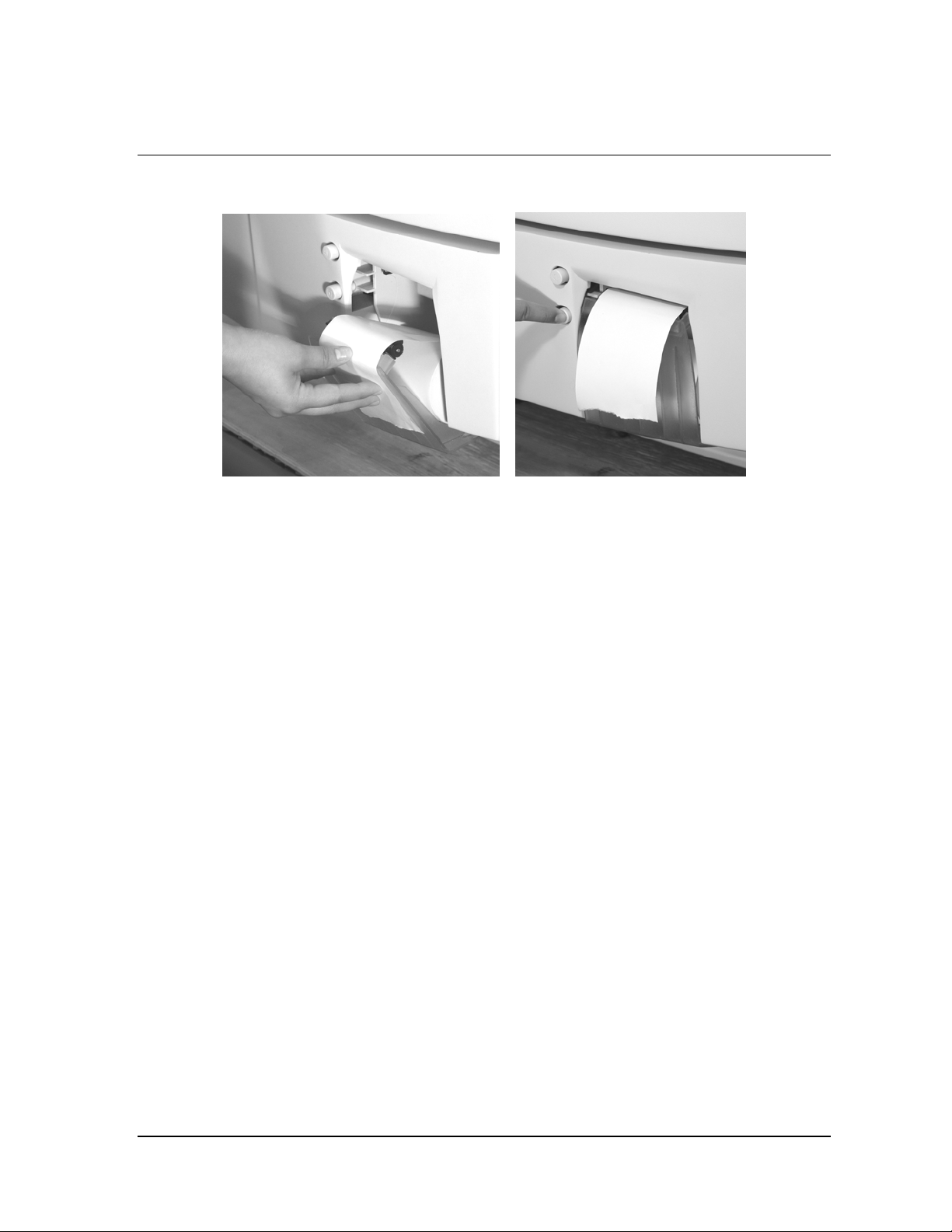
Maintenance 8
6. Hold the paper in place as you push the door shut.
Figure 50. Hold the Paper as You Shut the Printer Door. Press the Paper Advance Button.
7. Push the bottom button to advance the paper. Check the alignment of
the paper and make certain it does not jam or misfeed.
8. When the paper has advanced normally, tear off the used strip in an
upward direction. Paper replacement is now complete.
STERRAD® NX™ User’s Guide 85
Page 86

8 Maintenance
Cleaning the Sterilizer Exterior
4 Note: Do not attempt to clean the chamber, door, interior
surfaces, shelves, or electrode. If these items need
cleaning, in the U.S.A. call the ASP Customer Care
Center. Internationally, call your local ASP
Customer Support Representative for assistance.
The sterilizer exterior can be cleaned with a soft cloth and a mild,
nonabrasive detergent solution if necessary. When cleaning the sterilizer
exterior, follow these guidelines:
1. Turn off the power to the sterilizer before cleaning the exterior.
2. Never allow cleaning solution or water to enter the interior or chamber.
Moisten a cloth with nonabrasive detergent solution and use the damp
cloth to clean the surfaces.
3. Do not spray cleaning solution directly on the touch screen. Use a
dampened cloth to clean the screen.
4. If you have any questions about proper cleaning techniques, in the
U.S.A. please call the ASP Customer Care Center. Internationally, call
your local ASP Customer Support Representative before proceeding.
Failure to follow these guidelines may result in damage to the sterilizer
and may void the warranty.
Cleaning the Hydrogen Peroxide Monitor Detector Lens
The hydrogen peroxide monitor lens must be kept clean. Clean the lens
once every three months or when an accumulation of debris is noted. The
lens is shown in the following figure.
86 STERRAD® NX™ User’s Guide
Page 87
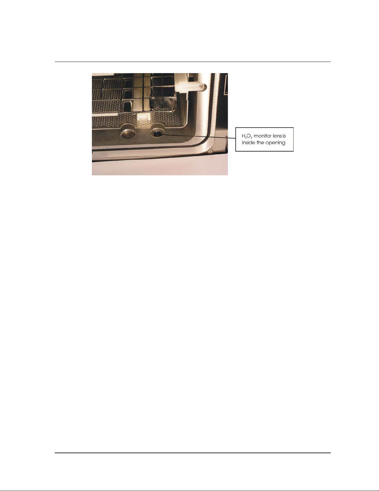
Maintenance 8
Figure 51. Hydrogen Peroxide Monitor Lens.
♦ Always use a lint-free cloth to clean the lens.
♦ Moisten the cloth with isopropyl alcohol. Never use an abrasive
cleanser.
Replacing the Air Filter
The air filter should be replaced when it is clogged with dust or debris.
Periodically check the air filter for dust and debris. Refer to Appendix B for
information on purchasing air filters for the STERRAD
To replace the air filter follow these guidelines:
1. Remove the nut that holds the flange of the air filter to the sterilizer.
Save the nut.
2. Pull the air filter straight out. Do not pull it up or bend it (see the
following figure).
3. Orient the new air filter as shown in the following figure.
®
NX™ Sterilizer.
STERRAD® NX™ User’s Guide 87
Page 88
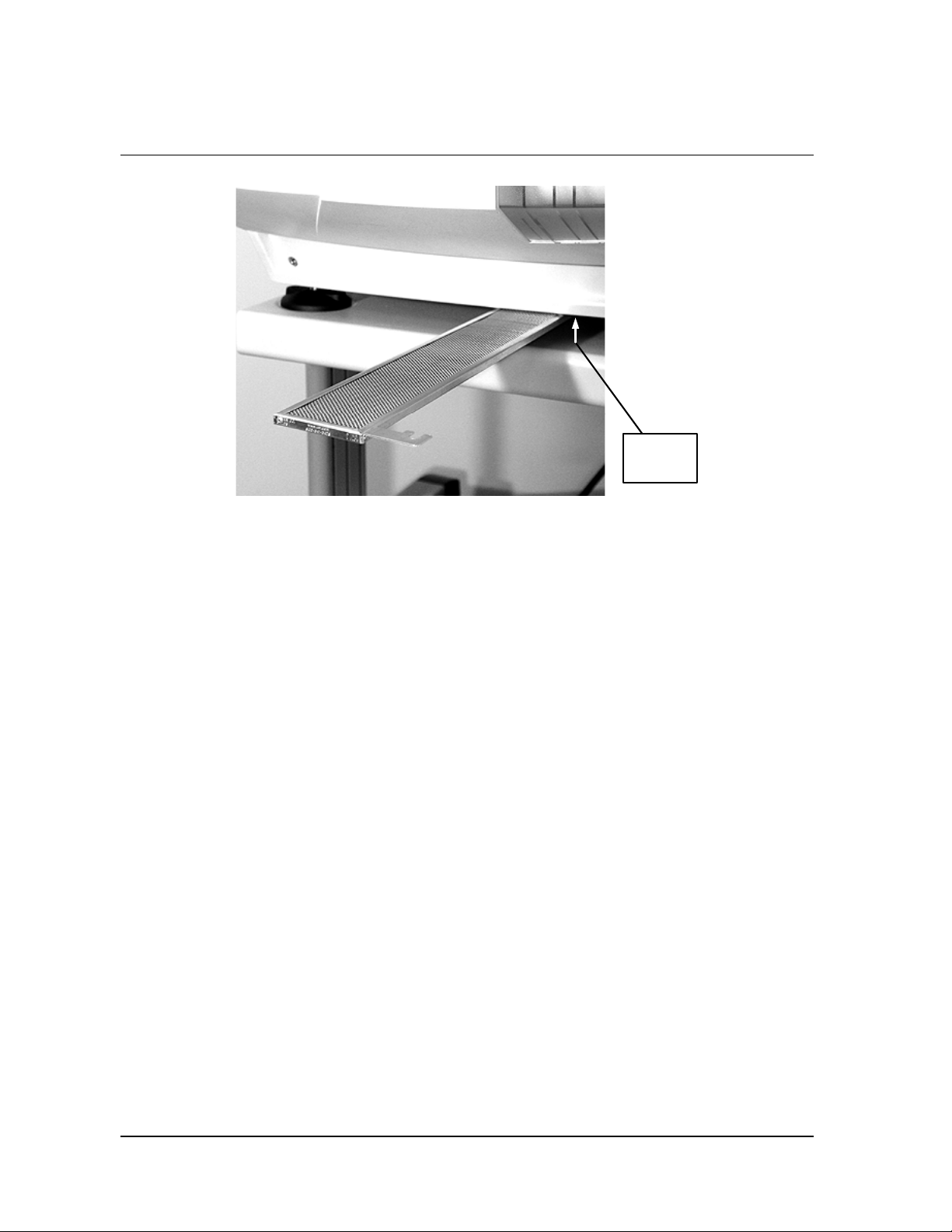
8 Maintenance
Location
of nut
Figure 52. Air Filter.
4. Slide the new air filter into the sterilizer until it is firmly seated.
5. Replace and tighten the nut that attaches the air filter to the sterilizer.
6. Discard the used air filter as directed by your facility’s policy.
PCMCIA Card Handling and Replacement
The PCMCIA card contains the flash memory used to store cycle data. If
you wish to save cycle data and do not have a network connection, the
cycle data can be transferred directly from the PCMCIA card to a computer
equipped with a PCMCIA card slot. To access the cycle data, perform the
following steps:
1. Turn off the sterilizer.
2. Eject the PCMCIA card by pressing the eject button on the left of the
card slot (see the following figure ).
The card can now be inserted into a computer to transfer the files. Refer to
the operating instructions of your computer before installing a PCMCIA
card in your computer. Once the cycle data is transferred, the PCMCIA
card must be reinserted in the sterilizer by following these steps:
1. Examine the PCMCIA card.
88 STERRAD® NX™ User’s Guide
Page 89
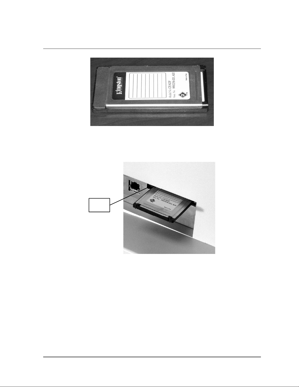
Maintenance 8
Figure 53. PCMCIA Card.
2. Orient the PCMCIA card so that the side of the card shown in the
following figure faces up.
3. Insert the card into the PCMCIA card slot as shown below.
Eject
button
Figure 54. PCMCIA Card Partially Inserted.
4. Press the end of the PCMCIA card until the card is firmly seated in the
slot (you will feel a “click” as the card is seated in the connector). A
properly seated card is shown in the following figure.
STERRAD® NX™ User’s Guide 89
Page 90
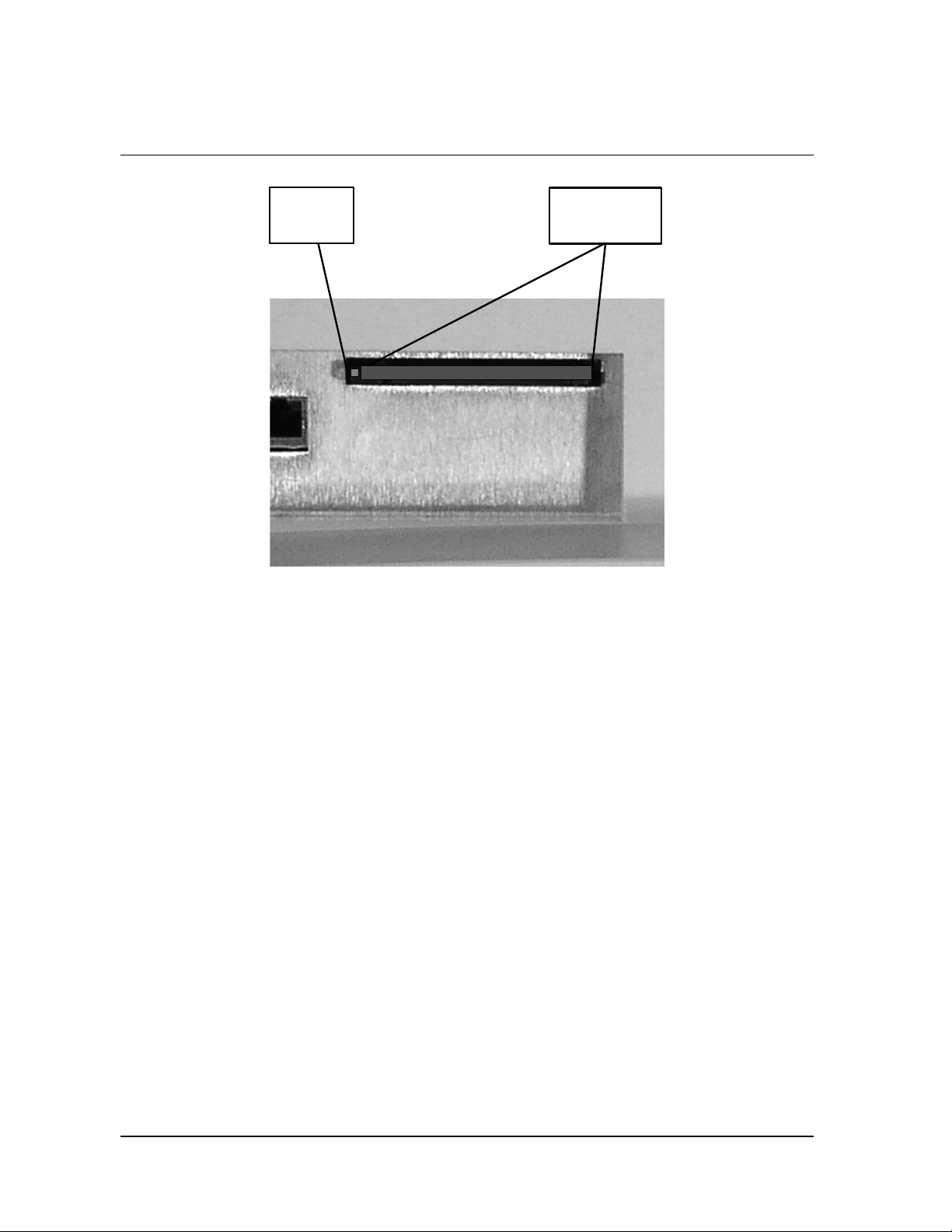
8 Maintenance
Eject
button
Figure 55. PCMCIA Card Seated in the Slot.
Alternatively, you may choose to save the PCMCIA card for your records.
If you wish to save the card, replace the PCMCIA card in your sterilizer
with a new card. Replacement cards are available from ASP and ordering
information is provided in Appendix B of this user’s guide.
PCMCIA
card in slot
4 Note: The STERRAD NX Sterilizer will not operate unless
the PCMCIA card is properly installed.
Sterilizer Disposal
In the event that disposal of the STERRAD NX Sterilizer is necessary, the
machine may be returned to ASP, recycled with a local recycler, or
disposed of in a local landfill. Disposal of infectious waste, electronic
circuit boards, and cathode ray tubes (CRTs) are regulated by the U.S.
Environmental Protection Agency and most international environmental
agencies. Please ensure compliance with all International, Federal, State,
and Local regulations before disposal. Contact your ASP Customer Care
Representative for additional information.
90 STERRAD® NX™ User’s Guide
Page 91

Troubleshooting 9
Chapter 9.
Troubleshooting
4
Note: Repairs and adjustments should only be made by ASP
trained and authorized personnel.
Most sterilizer operating problems are accompanied by a system message.
These messages are useful in determining the source of the problem. In
many cases you can take remedial actions to correct the source of the
problem and thereby return the sterilizer to normal operation. In other
cases, the problem is caused by a component failure that requires
adjustment or repair by an ASP Service Representative. Call the ASP
Customer Care Center at 1-888-STERRAD (1-888-783-7723).
Internationally, call your local ASP Customer Support Representative.
STERRAD® NX™ User’s Guide 91
Page 92

9 Troubleshooting
System Messages
Some system messages indicate conditions that you may be able to remedy.
Refer the following table for details.
4 Note: If a system message is not found in the following
table, there is no remedy available that you may
safely perform. Call the ASP Customer Care Center
for assistance.
System Message Probable Cause Suggested Remedy
CASSETTE ACCEPTED,
POSITIONING...
CASSETTE DETECTED,
VERIFYING...
CASSETTE DID NOT
INDEX
CASSETTE EXPIRY
FOUND DURING START
CYCLE
CASSETTE SYSTEM
TIMEOUT
CASSETTE SYSTEM
TIMEOUT ON
INDEXING
CYCLE CANCELED BY
OPERATOR
DISPOSING CASSETTE... A user disposed of the cassette
The barcode has been read and
the cassette has been positioned
at cell 1.
A cassette has been detected and
the barcode data is being read.
A cassette error occurred or the
cassette did not index.
The cassette was found to be
expired when the Start Cycle
button was pressed.
A timeout occurred in the
cassette system.
The cassette could not index to
the next cell.
The operator canceled the cycle. None required.
or there are no remaining cells
in the cassette.
None required.
None required.
Run diagnostics.
Dispose cassette and insert new
cassette.
Run diagnostics.
Run diagnostics.
None required.
H2O2 ADJUSTMENT
FAILED
H2O2 ADJUSTMENT IN
PROGRESS
H2O2 BULB WARMING
UP
92 STERRAD® NX™ User’s Guide
The maximum intensity of the
UV lamp has been reached.
The intensity of the UV lamp is
being adjusted.
The UV lamp is warming up. None required.
Call your ASP Customer Care
Representative.
None required.
Page 93
Troubleshooting 9
System Message Probable Cause Suggested Remedy
H2O2 CURVE AREA
TOO LOW
The calculated H2O2 area under
the time-temperature curve is
less than the threshold value set
in the CCF.
H2O2 RATE CONSTANT
TOO HIGH
The calculated rate constant for
H
is greater than the
2O2
threshold value set in the CCF.
INJECT SETUP
TIMEOUT
The time needed to initialize the
injection stage has expired.
INJECT TIMEOUT The time needed to inject
hydrogen peroxide into the
chamber has expired.
MEMORY CARD FULL More than 50 cycle records are
contained on the PCMCIA card.
The next cycle record will
overwrite the oldest cycle
record.
PLEASE CLOSE DOOR The door was opened while the
system was warming up.
PLEASE INSERT NEW
No cassette was detected. Insert a valid cassette.
CASSETTE
Run diagnostics. Call your ASP
Customer Care Representative.
Run diagnostics. Call your ASP
Customer Care Representative.
Run diagnostics. Call your ASP
Customer Care Representative.
Run diagnostics. Call your ASP
Customer Care Representative.
Store cycle record information
from PCMCIA card on an
external PC.
Close the door.
PLEASE OPEN DOOR Displayed after cycle
Open the door.
completion. The load is ready
for removal.
POWER FAIL
CANCELLATION
POWER SUPPLY OUT
OF RANGE
PRESSURE OUT OF
RANGE (Low)
A power failure occurred during
a cycle.
A power supply voltage is 20%
higher or lower than specified.
There is a pressure problem
with the vacuum system.
Call your ASP Customer Care
Representative.
Run diagnostics.
Run diagnostics. Call your
ASP Customer Care
Representative.
SYSTEM FAILURE CALL ASP.
SYSTEM PROBLEM CALL ASP!
A software error has occurred. Call your ASP Customer Care
Representative.
A system error has occurred. Call your ASP Customer Care
Representative.
STERRAD® NX™ User’s Guide 93
Page 94
9 Troubleshooting
System Message Probable Cause Suggested Remedy
UNABLE TO LIGHT
PLASMA. USE EXTRA
CAUTION WHEN
HANDLING THIS LOAD.
UNABLE TO OPEN ONE
SECOND DATA FILE
VACUUM TIMEOUT The time needed to evacuate the
VENTING PLEASE
WAIT…
WARMING UP, PLEASE
WAIT...
The plasma did not light during
canceled cycle.
A bad or missing PCMCIA
compact flash memory.
chamber has expired.
The chamber is venting until it
reaches atmospheric pressure.
The sterilizer is warming up. None required.
Diagnostic Messages
If an error occurs during operation, the sterilizer may allow you to run a
diagnostic test immediately. When prompted to do so, touch the Confirm
button to perform the diagnostic test. A diagnostic test displays and prints a
diagnostic message when the test is completed. Some diagnostic messages
indicate conditions that you may be able to remedy.
Run diagnostics. Call your ASP
Customer Care Representative.
Call your ASP Customer Care
Representative.
Run diagnostics. Call your ASP
Customer Care Representative.
None required.
4Note: If a diagnostic message is not found in the following
table, there is no remedy available that you may
safely perform. Call the ASP Customer Care Center
for assistance.
Message Probable Cause Suggested Remedy
12 VOLT SUPPLY HIGH 12 volt DC supply > 14.4
volts.
12 VOLT SUPPLY LOW 12 volt DC supply < 9.6
volts.
15 VOLT SUPPLY HIGH 15 volt DC supply > 18 volts. Call your ASP Customer Care
15 VOLT SUPPLY LOW 15 volt DC supply < 12 volts. Call your ASP Customer Care
24 VOLT SUPPLY HIGH 24 volt DC supply > 28.8
volts.
24 VOLT SUPPLY LOW 24 volt DC supply < 19.2 Call your ASP Customer Care
94 STERRAD® NX™ User’s Guide
Call your ASP Customer Care
Representative.
Call your ASP Customer Care
Representative.
Representative.
Representative.
Call your ASP Customer Care
Representative.
Page 95
Troubleshooting 9
Message Probable Cause Suggested Remedy
volts. Representative.
3.3 VOLT SUPPLY HIGH 3.3 volt DC supply > 3.96
volts.
3.3 VOLT SUPPLY LOW 3.3 volt DC supply < 2.64
volts.
Call your ASP Customer Care
Representative.
Call your ASP Customer Care
Representative.
5 VOLT SUPPLY HIGH 5 volt DC supply > 6 volts. Call your ASP Customer Care
Representative.
5 VOLT SUPPLY LOW 5 volt DC supply < 4 volts. Call your ASP Customer Care
Representative.
AIR PUMP SENSOR
READ OFF
AIR PUMP SENSOR
READ ON
Air pump mechanical failure
or air pump sensor failure.
Air pump mechanical failure
or air pump sensor failure.
Call your ASP Customer Care
Representative.
Call your ASP Customer Care
Representative.
ALARMS NOT HEARD Alarms not functioning. Verify annunciation of alarms. If
the problem persists, call your
ASP Customer Care
Representative.
ATM SWITCH STUCK
AT ATMOSPHERE
ATM SWITCH STUCK
AT VACUUM
Atmospheric switch failure. Call your ASP Customer Care
Representative.
Atmospheric switch failure. Call your ASP Customer Care
Representative.
BAD MONITOR UV monitor not functional. Verify pathway between UV
lamp and monitor is blocked. If
the problem persists, call your
ASP Customer Care
Representative.
BARCODE FAILURE Barcode scanner did not read
barcode label.
Verify cassette is inserted
correctly. Verify barcode. If the
problem persists, Call your ASP
Customer Care Representative.
CANNOT TURN
PLASMA OFF
CARRIAGE SENSOR
FAILURE
Plasma power out of
specification.
Carriage sensor not
functional.
Call your ASP Customer Care
Representative.
Verify cassette is inserted all the
way in. If problem persists, call
your ASP Customer Care
Representative.
STERRAD® NX™ User’s Guide 95
Page 96
9 Troubleshooting
Message Probable Cause Suggested Remedy
CASSETTE MOTOR
FAILURE
CASSETTE SYSTEM
TIMEOUT
CHAMBER 1
TEMPERATURE RAILED
HIGH
CHAMBER 1
TEMPERATURE RAILED
LOW
CHAMBER 2
TEMPERATURE RAILED
HIGH
CHAMBER 2
TEMPERATURE RAILED
LOW
CHAMBER DELTA TOO
BIG
Cassette motor not functional. Verify cassette is inserted all the
way in. If problem persists, call
your ASP Customer Care
Representative.
System could not
communicate with delivery
subsystem.
Thermistor circuit failure. Call your ASP Customer Care
Thermistor disconnected. Call your ASP Customer Care
Thermistor circuit failure. Call your ASP Customer Care
Thermistor disconnected. Call your ASP Customer Care
The chamber temperature
difference was larger than
expected. A sensor or heater
may have failed.
Call your ASP Customer Care
Representative.
Representative.
Representative.
Representative.
Representative.
Call your ASP Customer Care
Representative.
CHAMBER LOW/HIGH
SELECT FAILURE
CHAMBER PRESSURE
RAILED HIGH
CHAMBER PRESSURE
RAILED LOW
CHAMBER1
TEMPERATURE DID
NOT DROP
CHAMBER1
TEMPERATURE DID
NOT RISE
CHAMBER2
TEMPERATURE DID
96 STERRAD® NX™ User’s Guide
Chamber heater not
functioning within
specification.
Chamber pressure always
reads 30 torr.
Chamber pressure always
reads 0 torr.
Chamber heater will not shut
off.
Chamber heater/sensor not
functioning within
specification.
Chamber heater will not shut
off.
Call your ASP Customer Care
Representative.
Call your ASP Customer Care
Representative.
Call your ASP Customer Care
Representative.
Call your ASP Customer Care
Representative.
Call your ASP Customer Care
Representative.
Call your ASP Customer Care
Representative.
Page 97
Troubleshooting 9
Message Probable Cause Suggested Remedy
NOT DROP
CHAMBER2
TEMPERATURE DID
NOT RISE
COLLECTION BOX
FAILURE – FULL
WARNING! HYDROGEN PEROXIDE MAY BE PRESENT.
Wear latex, PVC (vinyl), or nitrile gloves whenever handling disposed
cassettes. Hydrogen peroxide liquid may be present on the cassettes.
COLLECTION BOX
FAILURE - NOT FULL
CONDENSER FAN NOT
OFF
CONDENSER FAN NOT
ON
Chamber heater/sensor not
functioning within
specification.
Collection box is not present
or properly positioned.
Disposed cassette did not end
up in collection box.
Condenser fan electrical
failure.
Condenser fan not
functioning.
Call your ASP Customer Care
Representative.
Verify collection box is present
and positioned properly. If
problem persists, call your ASP
Customer Care Representative.
Wear gloves and open collection
box drawer and free up any
jammed cassettes. If problem
persists, call your ASP Customer
Care Representative.
Call your ASP Customer Care
Representative.
Call your ASP Customer Care
Representative.
CONDENSER
TEMPERATURE DID
Condenser heater will not
shut off.
Call your ASP Customer Care
Representative.
NOT DROP
CONDENSER
TEMPERATURE DID
NOT RISE
CONDENSER
TEMPERATURE TOO
HIGH
Condenser heater/sensor not
functioning within
specification.
The condenser temperature
was higher than expected. A
sensor or heater may have
Call your ASP Customer Care
Representative.
Run diagnostics.
failed.
CONDENSER
TEMPERATURE TOO
LOW
The condenser temperature
was lower than expected. A
sensor or heater may have
Run diagnostics.
failed.
CONDENSER
TEMPERATURE RAILED
Thermistor circuit failure. Call your ASP Customer Care
Representative.
HIGH
STERRAD® NX™ User’s Guide 97
Page 98
9 Troubleshooting
p
Message Probable Cause Suggested Remedy
CONDENSER
TEMPERATURE RAILED
LOW
DELIVERY VALVE
SENSOR READ CLOSED
DELIVERY VALVE
SENSOR READ OPEN
DISPLAY TEST
FAILURE
DISPOSE FAILURE Collection box not present. Verify cassette was disposed into
DOOR FAN STUCK OFF Door fan not functioning. Call your ASP Customer Care
DOOR FAN STUCK ON Door fan not functioning. Call your ASP Customer Care
DOOR SENSOR STUCK
CLOSED
Thermistor disconnected. Call your ASP Customer Care
Representative.
Delivery valve mechanical
failure.
Delivery valve mechanical
failure.
Touch panel not functioning. Verify pressing of specified
Door sensor electrical failure. Call your ASP Customer Care
Call your ASP Customer Care
Representative.
Call your ASP Customer Care
Representative.
target. If problem persists, call
your ASP Customer Care
Representative.
the collection box. If problem
persists, call your ASP Customer
Care Representative.
Representative.
Representative.
Representative.
DOOR SENSOR STUCK
OPEN
DOOR TEMPERATURE
DID NOT DROP
DOOR TEMPERATURE
DID NOT RISE
DOOR TEMPERATURE
RAILED HIGH
DOOR TEMPERATURE
RAILED LOW
EJECT FAILURE Cassette did not eject. Verify cassette is not ejected. If
FAILED TO EXTEND Needle motor not functional. Verify needles extend. If problem
98 STERRAD® NX™ User’s Guide
Door sensor electrical failure. Call your ASP Customer Care
Representative.
Door heater will not shut off. Call your ASP Customer Care
Representative.
Door heater/sensor not
functioning within
specification.
Thermistor circuit failure. Call your ASP Customer Care
Thermistor disconnected. Call your ASP Customer Care
Call your ASP Customer Care
Representative.
Representative.
Representative.
problem persists, call your ASP
Customer Care Representative.
ersists, call your ASP Customer
Page 99
Troubleshooting 9
Message Probable Cause Suggested Remedy
NEEDLE Care Representative.
FAILED TO RETRACT
NEEDLE
Needle motor not functional. Verify needles retract. If problem
persists, call your ASP Customer
Care Representative.
HIGH PLASMA POWER Plasma power out of
specification.
INLET COMMAND
Inlet valve electrical failure. Call your ASP Customer Care
ALWAYS CLOSED
INLET COMMAND
Inlet valve electrical failure. Call your ASP Customer Care
ALWAYS OPEN
LOW PLASMA POWER Plasma power out of
specification.
Run diagnostics. Call your ASP
Customer Care Representative.
Representative.
Representative.
Run diagnostics. Call your ASP
Customer Care Representative.
MAIN FAN STUCK OFF Main fan not functioning. Call your ASP Customer Care
Representative.
NO PLASMA POWER Plasma power out of
specification.
OIL RETURN VALVE
STUCK CLOSED
OIL RETURN VALVE
STUCK OPEN
Oil return valve mechanical
failure.
Oil return valve mechanical
failure.
Call your ASP Customer Care
Representative.
Call your ASP Customer Care
Representative.
Call your ASP Customer Care
Representative.
PRINTER TEST FAILURE Printer not printing. Verify data printed. If problem
persists, call your ASP Customer
Care Representative.
PUMP ALWAYS OFF Vacuum pump electrical
failure.
PUMP ALWAYS ON Vacuum pump electrical
failure.
UNABLE TO LOCK
Door lock mechanical failure. Call your ASP Customer Care
DOOR
VACUUM COMMAND
ALWAYS OPEN
VACUUM CONTROL
VALVE STUCK CLOSED
VACUUM CONTROL
VALVE STUCK OPEN
Vacuum valve mechanical
failure.
Vacuum control valve
mechanical failure.
Vacuum control valve
mechanical failure.
Call your ASP Customer Care
Representative.
Call your ASP Customer Care
Representative.
Representative.
Call your ASP Customer Care
Representative.
Call your ASP Customer Care
Representative.
Call your ASP Customer Care
Representative.
STERRAD® NX™ User’s Guide 99
Page 100
9 Troubleshooting
Message Probable Cause Suggested Remedy
VACUUM
INSUFFICIENT FOR
PLASMA
VACUUM SENSOR
STUCK CLOSED
VACUUM SENSOR
STUCK OPEN
VAPORIZER PRESSURE
RAILED HIGH
VAPORIZER PRESSURE
RAILED LOW
VAPORIZER
TEMPERATURE DID
NOT DROP
VAPORIZER
TEMPERATURE DID
NOT RISE
VAPORIZER
TEMPERATURE RAILED
HIGH
Leak in chamber or wet load
in chamber.
Vacuum valve sensor failure. Call your ASP Customer Care
Vacuum valve sensor failure. Call your ASP Customer Care
Vaporizer pressure always
reads 200 torr.
Vaporizer pressure always
reads 0 torr.
Vaporizer heater will not shut
off.
Vaporizer heater/sensor not
functioning within
specification.
Thermistor circuit failure. Call your ASP Customer Care
Remove load. Verify door is
closed. If problem persists, call
your ASP Customer Care
Representative.
Representative.
Representative.
Call your ASP Customer Care
Representative.
Call your ASP Customer Care
Representative.
Call your ASP Customer Care
Representative.
Call your ASP Customer Care
Representative.
Representative.
VAPORIZER
TEMPERATURE RAILED
LOW
VENT SENSOR STUCK
CLOSED
VENT SENSOR STUCK
OPEN
VENT VALVE
COMMAND ALWAYS
CLOSED
VENT VALVE
COMMAND ALWAYS
OPEN
VENT VALVE
PARTIALLY OCCLUDED
VENT VALVE STUCK Vent valve mechanical Call your ASP Customer Care
100 STERRAD® NX™ User’s Guide
Thermistor disconnected. Call your ASP Customer Care
Representative.
Vent valve sensor failure. Call your ASP Customer Care
Representative.
Vent valve sensor failure. Call your ASP Customer Care
Representative.
Vent valve electrical failure. Call your ASP Customer Care
Representative.
Vent valve electrical failure. Call your ASP Customer Care
Representative.
Filter on vent valve needs
cleaning or replacement.
Call your ASP Customer Care
Representative.
 Loading...