

Page 1
ULTRALIGHT LX
Engl
Engf
Deui
Fran
Italia
Espi
■ PRESENTATIONS
■ WORKING SESSIONS
■ TRAINING
■ MULTIMEDIA
■ ANIMATION
■ VIDEO
Page 2

INFORMATION TO THE USER
NOTE: This equipment has been tested and found to comply with the limits for a Class A digital
pursuant to Part 15 of FCC Bufes. These limits are designed to provide reasonable protection
..............
As the owner of a new ULTRALIGHT LX, you are probably eager to try out your new projector. Befc
do, we suggest that your spend a little time reading this manual to familiarize yourself with the op
procedures, so that you will receive maximum satisfaction from the many features included in yoi
projector.
This owner's manual will acquaint you with your projector's features. Reading it will help us too, Throu
years, we have found that many service requests were not caused by problems with our projectors,
were caused by problems that could have been prevented, if the owner had followed the instructions
manual.
You can often correct operating problems yourself. If your projector fails to work proper!;
"TROUBLESHOOTING" section on page 36-37 and try the solution marked for each problem,
WARNING: |
TO REDUCE THE RISK OF FIRE OR ELECTRIC SHOCK, DO NOT EXPOSE THIS APPLIANCE TO RA
MOISTURE.
HSfmfCtl interference' when- the-equipment is-operated in-a-commercial environment. This eq
generates, uses, and can radiate radio frequency energy and, if not instafied and used irr acc<
with the instruction manual, may cause harmful interference to radio communications. Oper
this equipment in a residential area is likely to cause harmful interference irt which case the i
be required to correct the interference at his own expense.
TO THE OV/NER
SAFETY PRECAUTrONS
This Projector has a grounding-type AC line plug. This is a safety feature to be sure that the plug i
into the power outlet. Do not try to defeat this safety feature.
This projector produces intense light from the projection lens. Do not stare directly into the iei
possible eye damage could result. Be especially careful that children do not stare directly into the be
The Remote Control Unit, supplied to this projector, emits the laser beam as the Laser Pointer fur
from the Laser Light Window while pressing the LASER button. Do not took into the Laser Light Wi
or shine the laser beam on yourself or other people. Eye damage may result.
This projector should be set in the way indicated. If not, ft may result in fire hazard.
H the projector will not be used for an extended time, unplug the projector from the power outlet,
READ AND KEEP THIS OWNER'S MANUAL FOR LATER USE.
CAUTION
ррщ£ста1с зносж
A
CAUTION ; TO REDUCE THE RISK OF ELECTRIC SHOCK, DO NOT REMOVE COVER (OR BA
NO USER-SERVICEABLE PARTS INSIDE EXCEPT LAMP REPLACEMENT. RE
SERVICING TO QUALIFIED SERVICE PERSONNEL.
THIS SYMBOL INDICATES THAT
DANGEROUS VOLTAGE CONSTITUTING
A
A RISK OF •ELECTRIC SHOCK IS
PRESENT WITHIN THIS UNIT.
‘lîèiNOTbPEN
A
A
■ THIS SYMBOL INDICATES THAT ^
ARE IMPORTANT OPERATING
MAINTENANCE INSTRUCTIONS IN
USER'S GUIDE WITH THIS UNIT,
Page 3
IMPORTANT SAFETY INSTRUCTIONS
Ali the safety and operating instructions should be read before
the product is operated.
Read ail of the insiroctions given here and retain them for
later use. Unpiug this projector from AC power supply before
cleaning. Do not use liquid or aerosol cleaners. Use a damp
cloth for cleaning.
Do not Use attachments not recommended by the
manuiacturer as they may cause hazards.
Do not place this projector on an unstable cart, stand, or
Sable. The projector may fall, causing serious injury to a child
or adult, and serious damage to the projector. Use only with
a cart or stand recommended by the manufacturer, or sold
with the projector. Wall of shelf mounting shoufd follow the
manufacturer's instructions, and should use a mounting kit
approved by the manufacturers.
Do not expose this unit to rain or use near water... for
example, in a wet basement, near a swimming pool, etc...
Slots and openings in the back and bottom of the cabinet are
provided for ventilation, to insure reliable operation of the
equipment and to protect if from overheating.
The openings should never be covered with cloth of other
materials, and the bottom opening should not be blocked by
placing the projector on a bed, sofa, rug, or other similar
surface. This projector should never be placed near or over a
radiator or heat register.
This projector should not be placed in a built-in insta(latior>
such as a book case unless proper ventilation is provided.
This projector should be operated only from the type of power
source indicated on the marking label. If you are not sure of
the type of power supplied, consult your authorized dealer or
local power company.
Do not overload wall outlets and extension cords as this can
resuit in fire or electric shock. Do not allow anything to rest
on the povrer cord. Do not locate this projector where the
cord may be damaged by persons walking on it
d. If the projector does not operate normally by folio'
operating instructions. Adjust only those controls
covered by the operating instructions as in
adjustment of other controls may result in damage
often require extensive work by a qualified techr
restore the projector to normal operation.
e. If the projector has been dropped or the cabinet h
damaged.
f. When the projector exhibits a distinct chs
performance-this indicates a need for service.
When repiacemerrt parts are required, be sure the
technician has used replacement parts specified
manufacturer that have the same characteristics
original part. Unauthorized substitutions may result
electric shock, or injury to persons.
Upon completion of any service or repairs to this pi
ask the service technician to perform routine safety ct
determine that the projector is in safe operating conditi
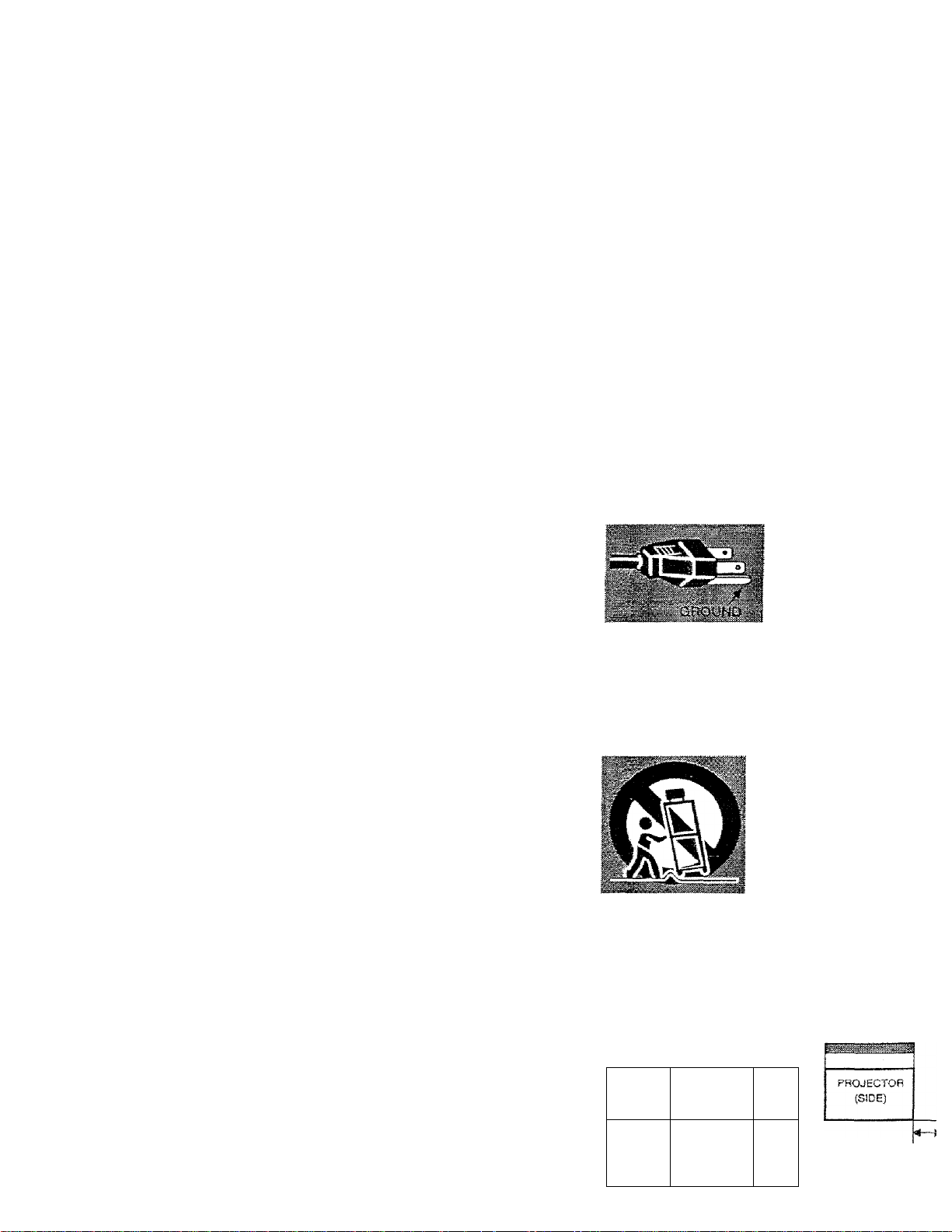
This projector is equtppec
grounding type AC lins
Should you be unable to in
plug into the outlet, conta
electrician. Do not dels
safety purpose of this grc
type plug.
Follow all warnings and instructions madded on the proj
For added protection to the projector during a lightning
Of when it is left urrattended and unused for long pes
time, unplug it from the wall outlet. This will prevent c
due to lightning and power line surges.
An appliance and cart comb
should be moved with care,
stops, excessive force, and ?
surfaces may cause the apj
and cart combination to overft
Never push objects of any kind into this projector through
cabinet slots as they may touch dangerous voltage points or
short out parts that could result in a fire or electric shock.
Never spiil liquid of any kind on the projector.
Do not attempt to service this projector yourself as opening or
removing covers may expose you to dangerous voltage or
other hazards. Refer all servicing to qualified service
personnel.
Unplug this projector from wall outlet and refer servicing to
qualified service personnel under the foilowlng conditions:
a. When the power cord or plug is damaged or frayed,
b. if liquid has been spilled into the projector.
c. If the projector has been exposed to rain or wafer.
If the projector is to be built into a compartment or s
enclosed, the minimum distances must be maintained.
Do not cover the ventilatiort slot on the projector.
Heat build-up can reduce the service life of your prc
and can also be dangerous.
20cm.
PROJECTOR
(FRONT}
T
SOcm 50cm
1
50a
Page 4

TABLE OF CONTENTS
FEATURES AND DESJGN
PREPARATION 6
NAME OF EACH PART OF THE PROJECTOR 6
SETTING-UP THE PROJECTOR 7
POSmONJNG THE
ADJUSTABLE
CONNECTING
VENTILATION 3
MOVING THE PROJECTOR 9
PHOJECTOR
FEET 3
THE
AC
POWER
CORD
8
CONNECTING THE PROJECTOR 10
TERMINALS OF THE PROJECTOR 10
CONNECTING TO THE VIDEO EQUIPMENT 11
CONNECTING TO THE IBM-COMPATIBLE COMPUTER 12
CONNECTING TO THE MACINTOSH COMPUTER 14
BEFORE OPERATION 16
8
COMPUTER MODE
SELECTiNG COMPUTER MODE
SELECTING COMPUTER SYSTEM
PC ADJUSTMENT
COMPATIBLE COMPUTER SPECIFICATIONS
PICTURE IMAGE ADJUSTMENT
PICTURE POSITION ADJUSTMENT
PICTURE SCREEN ADJUSTMENT
VIDEO MODE
SELECTING VIDEO MODE
SELECTiNG COLOR SYSTEM
PICTURE IMAGE ADJUSTMENT
PICTURE SCREEN ADJUSTMENT
SETTING
SETTING MENU
SELECTING LANGUAGE
f
OPERATION OF THE REMOTE CONTROL
TOP CONTROLS AND INDICATORS
OPERATING ON-SCREEN MENU
BASIC OPERATIONS
TURNING ON / OFF THE PROJECTOR
ADJUSTING THE PICTURE
NO SHOW FUNCTION
SOUND ADJUSTMENT
TRADEMARKS
• Apple, Macintosh, and PowerBook are trademarks or registered trademarks of Apple Compuier.lnc.
• IBM and PS/2 are trademarks or registered trademarks of international Business Machines, Inc.
• Each name of corporations or products in the USER'S GUIDE is a trademark or a registered trademark
respective corporation.
16
18
IS
21
21
22
23
23
APPENDIX
OPERATING WIRELESS MOUSE
MAINTENANCE
AIR FILTER CARE AND CLEANING
LAMP REPLACEMENT
TROUBLESHOOTING
TECHNICAL SPECIFICATIONS
Page 5

FEATURES AND DESIGN
This Multimedia Projector is designed with most advance technology for portability, durability, and ease for \
The projector utilizes built-in multimedia features, a palette of 16,77 million colors, and matrix liquid cry
display (LCD) technology.
♦ Compatibility
This projector is compatible with many different
types of persona! computers and video devices,
including;
9 iBM-compatible computers, including
laptops, up to 1280 X 1024 resolution.
• Apple Macintosh and PowerBook computers
up to 1280 X 1024 resolution.
• Various video equipment using any of the
world wide video standards, including NTSC,
NTSC4.43, SECAM, PAL. and PAL-M.
♦ image Resolution
Picture Image is projected in the resolution of
1024 X 768. The projector provides computer
images just as they appear on your computer's
monitor. Screen resolutions between 1024 x 768
and 1280 X 1024 are compressed to 1024 x 768.
The projector cannot display screen resolutions
over 1280 X 1024. if your computer's screen
resolution is higher than 1280 x 1024, reset it to a
lower resolution before you connect the projector.
♦ Portability
This projector is extremely compact in size and
. weight. Having a sophisticated shape like an
attaché case with a retractable carrying handle,
the projector will help you make powerful
presentation wherever you go.
» Automatic Multiscanning System
This projector can detect output signals from most
personal computers currently distributed. It is free
from complicated adjustments to project picture
images from PC.
__________
» Multilanguage Menu Di sp la y
Operation menu is displayed in; English, Deuh
Français, Italiano, Español, or Japanese.
♦ Laser Pointer Function
The Remote Control Unit of this projector has
Laser Pointer function, providing eas
presentation. Refer to the page 16 for operatic
♦ Other Features
This projector has No show, Digital zoom
Mute functions, and Air Pad Remote ControL
♦ Accessories
This projector comes with the parts listed bet«
Check to make sure all are included, if any pi
are missing, contact to a sales dealer.
• USER'S GUIDE. -
• AC Power Cord.
• Wireless Remote Control Unit.
• Batteries for Remote Control Unit.
• VGA Cable.
• VGA/MAC Adapter.
• Mouse Cable for PS/2 port.
• Mouse Cable for serial port.
• Mouse Cable for ADB port.
• PC Audio Cable (Stereo mini Jack).
AV Cable (RCA type x 3).
• S-VIDEO cable (Mini DIN-4 type).
• Lens Cover.
• Dust Cover.
• Carrying Bag,
Page 6
PREPARATION
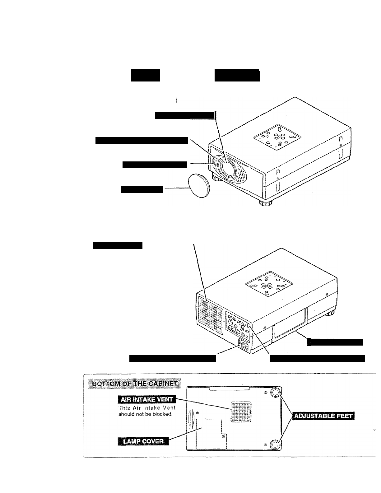
AME 'ARTíOF
FRONT OF THE CABINET
INFRARED REMOTE RECEIVER
SPEAIC^ №naural}
LENS COVER
L
PROJECTION LENS
EXHAUST VENT
HOT AIR EXHAUSTED 1
A
Air bfown from the exhaust vent is
hot. When using or insfaifing the
projector, following attention should
be taken.
• Do not put a flammafaie object near
this part.
Keep heat-sensitive objects away
from the exhaust vent.
• Do not touch this part especially
screws and metalUc parts. This part.
vdJf becoroe hot while the projector is
used.
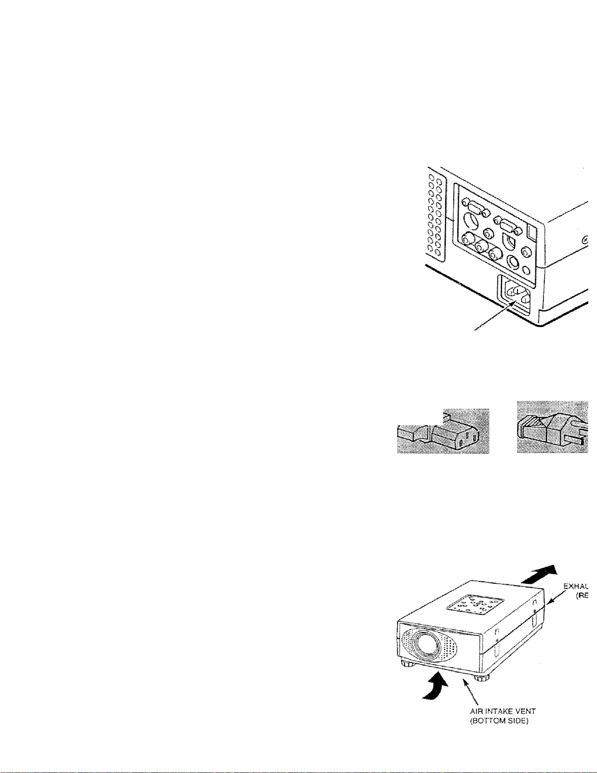
POWER CORD CONNECrOR
CARRY HANDLE
INFRARED REMOTE RECEIVER
Page 7
PREP^
................
........................
.......
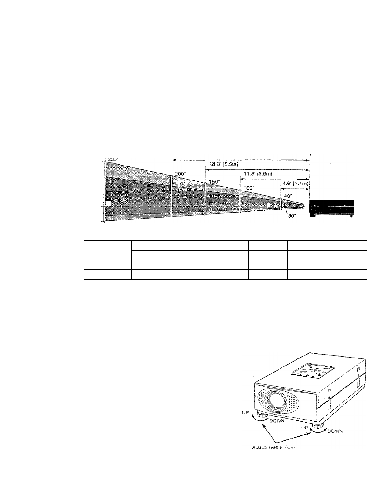
POSmONING THE PROJECTOR
• This projector Is basically designed to project on a flat projection surface.
• The projector can be focused from 4.6’(1.4m) ~ 35,4’(i0.8m).
• Refer to the figure betow to adjust the screen size.
¡35.4' {10.8m)
24.0' C7,3m)
HI
H2
Screen Size
fW X H) mm
Height (HI)
Height (H2)
30*
609X457
17.1'(435mm)
0.9'(22mm) 1.7"(44rrim) 4,3"(l09f»im|
60'
1219x914
34.3'{a70mra|
100’
2032 X
1524
S7.rc14S1mm)
3148 X 2266
85.r(2177rwn)
150"
200’
4064 X3048
114.3"{2903iram].
5.7”|l45mm)
300*
6096 X 4572
171.4’(:4354mm)
8,S'(2l8rr>m)
ROOM LIGHT
The brightness in the room has a great Influence on the picture quality. It is recommended to limit ambie
lighting in order to provide the best image.
ADJUSTABLE FEET
Picture tilt and pro|ection angfe can be adjttsted by
twisting ADJUSTABLE FEET. Projecllon angle can be
adjusted 0 to 2 degrees by rotating Adjustable Feet,
Page 8
PREPARATION
CONNECTING THE AC POWER CORD
This projector uses nominal input votlages of 100-120 V
or 200-240 V AC, The projector automatically selects
the correct input voltage. It is designed to work with
single-phase power systems having a grounded neutral
conductor. To reduce the risk of electrical shock, do not
plug into any other type of power system.
Consult your authorized dealer or service station if your
are not sure of the type of power supply being in use.
Connect the projector with the peripheral equipment
before turning the projector on. (Refer to pages 10 -15
for connection.)
'W_.-
A
CAUTION
For the safety, unplug the AC Power Cord when the
appliance is rtot used.
When this projector is connected to the outlet with
the AC Power Cord, the appliance is in Stand-by
Mode and consumes a little electric power.
VENTILATION
This projector is equipped cooling fans for protection from overheating. Pay attention to the fotlowini
ensure the ventilation and avoid a possible risk of fire and malfunciion.
• Do not cover the vent slot
• Keep the rear grill at least one meter away from any object.
• Make sure that there is no object under the projector. An
obstacle under the projector may prevent the projector from
taking the cooling air through the bottom vent slot.
Connerrf the AC power supply cord (supplied) to the pi
The socket-outlet must be rtear this equiprnent an<
easily accessible.
Prcjertor .sfdo (Female)
•
AC oiitiBt .= ce (Mj
•w-'
8
Page 9
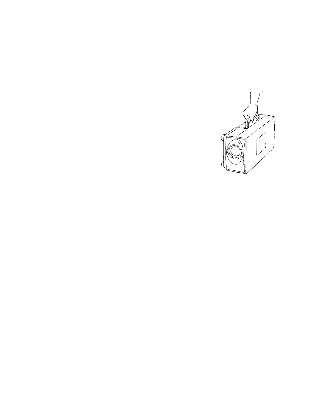
MOVING THE PROJECTOR
Use the Carry Handle when moving the Projector.
• Replace the lens cover and rotate the feet fuliy
clockwise (to shorten the feet) when moving the
projector to prevent damage to the cabinet
NOTE
The carrying bag (supplied) is intended for protection
from dust and scratches on the surface of the cabinet,
and it is not designed to protect the LCD projector from
externa) shock.
Do not drop the projector, subject it to strong forces, or
put other things on the cabinet when carrying the pro
jector with this bag. Do rsoi transport the projector
through a courier or transport services with this bag.
The projector can be damaged.
PREPAi
A
CAUTION IN CARRYING OR TRANSPORTING THE PROJECTOR
• Do not drop or give a shock to the projector, otherwise damages or malfunctions may result.
• When carrying the projector, use a carrying case recommended by Proxima.
• Do not transport the projector by using a courier or transport service in an unsuitable transport case. Tfmay cause damage to the projector. To transport the projector through a courier or transport service, u;
a case recommended by Proxima.
• For carrying or transportation cases, contact a Proxima authorized dealer.
Page 10
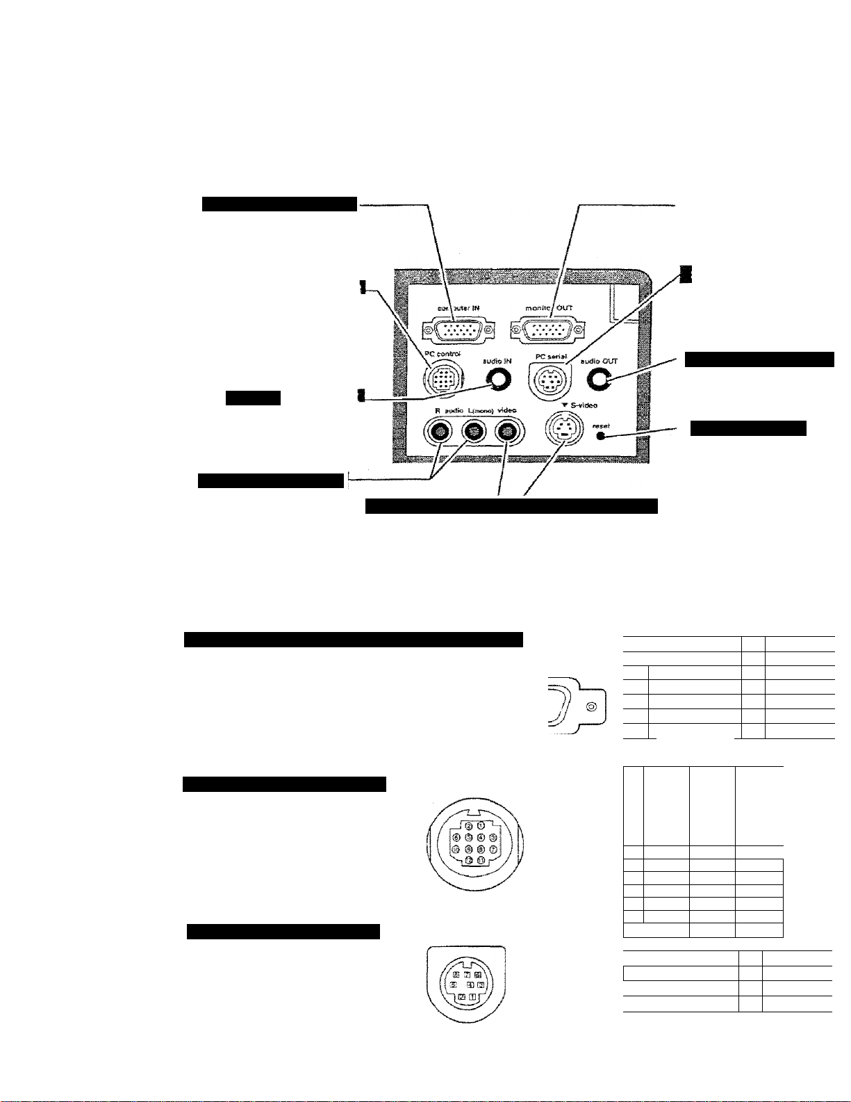
CONNECTING THE PROJECTOR
COiPüTSR INPUT TERMNAL
Connect the computer output
to this terminal.
{Refer to P12-15.)
When controlling the computer
with the Remote Control of this
projector, connect the mouse
port to this connector.
(Refer to P12 -15.)
PUTER AU
Connect the audio output from
the computer to this jack.
(Refer to P12~15.)
AWDiOWIJT JWCfCS
Connect the audio outputs
from the video equipment
fo these jacks,
(Refer to P11.)
• When the audio output is
monaural, connect it to
the AUDIO LEFT jack.
VIDEO INPUT IIACKI S-VIDEO INPUT JACK
Connect the video
output from the video
equipment to this jack.
(Refer to P11.)
Connect the S-VIDEO
output from the video
equipment to this jack.
(Refer to P11.)
Connect to the monitor to
terminai.
(Referto P12-16.)
This connector is usee
connect a computer to cor
this projector with the PC.
(Refer to P12-13.3
AUDIO OUTPUT JACK
Connect the audio antplifie
this jack.
(Referto P12 -16.)
RESET BUTTON
This projector uses a mi
processor to control the l
Occasionally, the mi
processor may malfunction
need to be reset. This can
done by pressing the RES
button with a pen, whichshut down the unit. Tuti
projector off and restart the*^
Do not use the RESET func
excessively.
COBIPUTÖ? INPUTf MONITOR OUTPUT TERMINAL
Terminai: HDB15-P1N
Connect the display output terminal of the
computer to this COMPUTER INPUT with ttie
VGA Cable (supplied), and connect the monitor
to this MONITOR OUTPUT with the rnonitor
cable (not supplied). When connecting the
Maoirttosh computer, the MACA/GA Adapter is
required (supplied).
COlWiOLiTORT CONNECTOR
Terminal: MULTI-POLE 12-PIN
When controlling the computer with ths
projector's Wireless Remote Control Unit,
connect control port (PS/2, Serial or ADB port]
on your computer to this connector. (These
Control Cables are suppiied.)
SERIAL POirr CONNECTOR
Terminal : D!N 8-PIN
This connector is used to connect a
to
control the projecicr with the PC. For this
connection, the Serial Cable is required (This
cable is not supplied).
compuier
Pin Configuration
(f© ® «3» © ©
W Ä CD d) d) <t>
■V
Pin Configuration
:Р1п Configuration
0 & ® ® ©
■ 2
рШ!
■
1
s
7
Rad Irrput
Green Input 10
Blue input
Sense 2
Ground (HoriiSync.)
Ground (Red)
Ground (Green) 1.5 Reserve«
Ground (Blue)
-3-;
-;---ri.ii
9 •
■M
12:
13
1Л
A AU
TXD
,.S
'10
■n
12Ì
;-1 :
^ 2 F
3
4
2
в
7
s
3 :
4 i
CLK
DATA
— —
—
—
GND GND
—
—
—
nXD
READY
..... —
R X D
ADB
MUX232
GND ß
ADS
GND
— —
—
----
■5
6
. ?
—
Non Conrii
Ground (Vsrt.i
Sense C
Sense 1
Horiz. syn
Vert, syni
1
—
;
MUX
TxD ■
10
Page 11
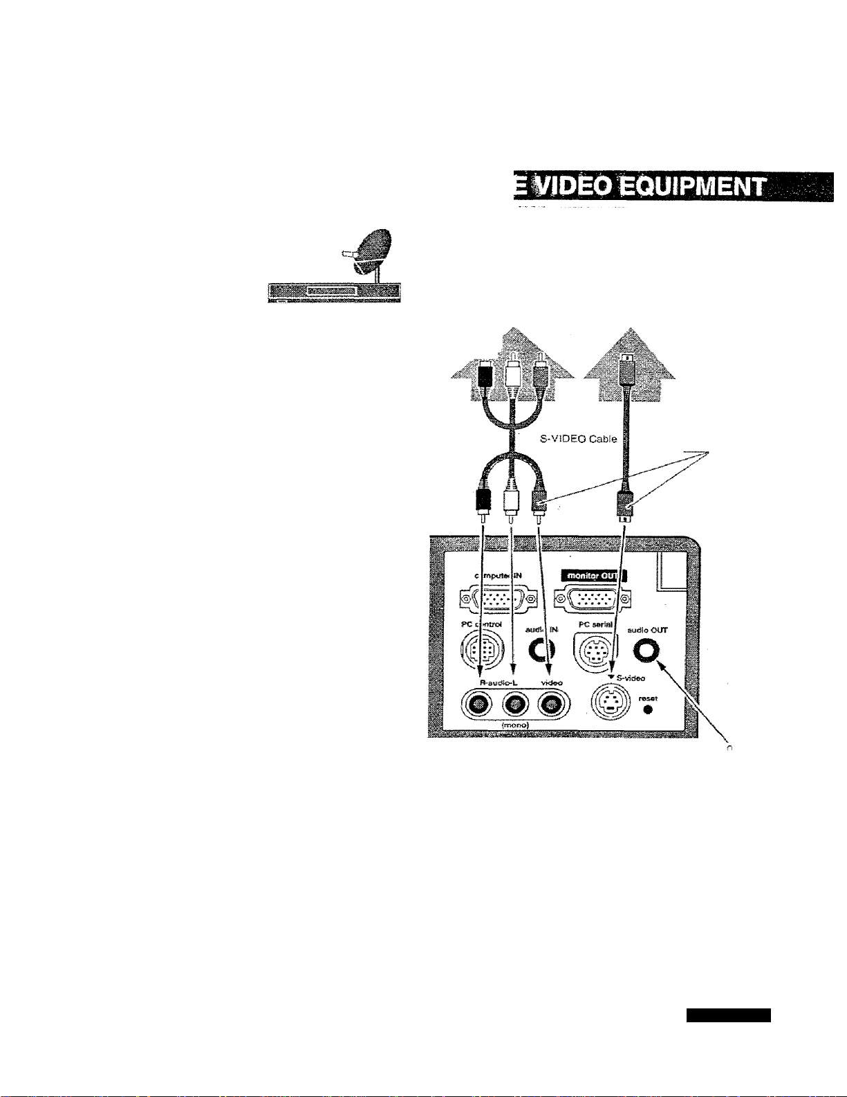
CONNECTING THE PROJ
Satellite
TV Turner
Used caoles fcr co”.rc-ction
• VIDEO CABLE
■ S-VtDEO CABLE
' AUDIO CABLE (stereo)
Video Cassette Recorder
Video / Audio Output
Video Audio Cable
Video Disc Player
S-VIDEO Output
Use me either of VIDEO jac
or S-ViDEO|ack. When the
both jacks are connected,
S-VIDEO jack has priority oi
me VIDEO jack.
Terminals
of the Projector
th
A
NOTE :
When connecting the cable, the power cords of
both the projector and the external equipment
should be disconnected from AC outlet Turn the
projector and peripheral equipment on before the
computer is switched on.
Externa! Audio Equipment
Audio Speaker
(stereo)
II-
Audio Cable (Ster.
,„<UC-d5pÜt
Audio Amplifier
Page 12
CONNECTING THE PROJECTOR
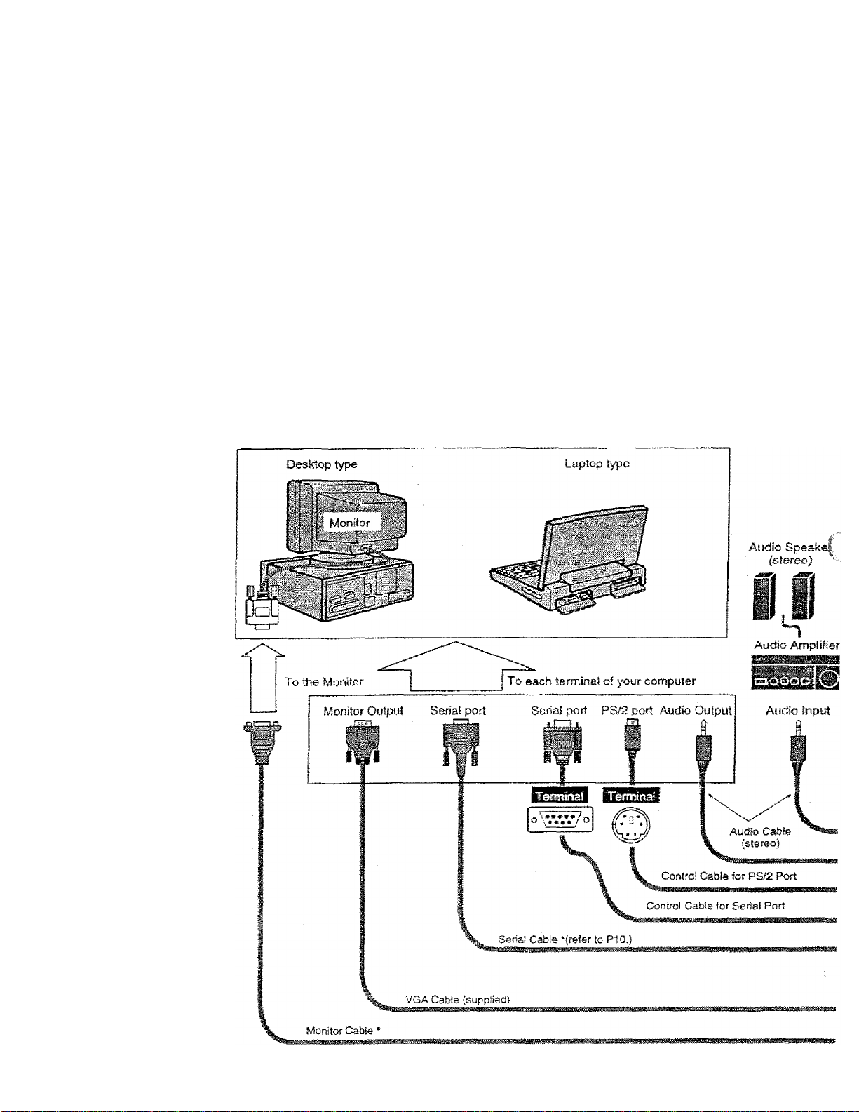
To connect with the iSM-compatibte computer, refer to the figure below.
• VGA CABLE
• CONTROL CABLE FOR PS/2 PORT or SERIAL PORT
• PC AUDIO CABLE (stereo)
• MONITOR CABLE *
-PC SERIAL GABLE*
• These cables are not supplied with this projector.
NOTE :
When connecting the cable, the power cords of both the projector and the external equipment shouic
I \ disconnected from AC outlet. Turn the projector and peripheral equipment on before the computer is switc
A
orr.
IBM-COMPATIBLE COMPUTERS (VGA / SVGA / XQA / SXGA)
12
Page 13

CONNECTING THE PROJ
MONiTOR OUT
Page 14

CONNECTING THE PROJECTOR
To connect with the Macintosh computer, refer to the figure below.
Used iiibles lor cofinection
• VGA CABLE
■ CONTROL CABLE FOR AD8 PORT
• MAC ADAPTER
• MONITOR CABLE *
> PC AUDIO CABLE (stereo)
" These cables are not supplied with this projector.
NOTE :
When connecting the cable, the power cords of both She projector and the external equipment sho:
• disconriected from AC outlet. Turn the projector and peripheral equipment on before the computer is sw
A
on.
MACINTOSH COMPUTERS {VGA / SVGA Ì XGA / SXGA}
MAC
'• »fijicties depBndiftg
»"■> . on the RESOLUTION MODE
' that you want to use before
Adapter
your Sum on the projector
and computar
To each terminal of your computer
A08 port
Terminaf
Audio Output
Audio Speaks
(stereo)
l|
Audio AmpJif
14
Page 15

CONNECTING THE PROJ
♦ V.AC.'VCA ADAPTER
i 'ill' > .1' ■ ■ Al
li', i‘ie* iarsifi belesv tfecersd-’
!f!5 iSi Ihe RESOLU riON' _
!■' -"J' Aa-H W
Us« ceicire year turn ori ii?s
p-rcl9fllo.''a'Ki computer. --
Page 16

BEFORE OPERATION
This remote control unit is not only able to operate the projector but afso usable as a wireless mouse for
POINT button and two CLICK buttons are used for wireless mouse operation. (Refer to page 33.)
Wireless mouse Is usable when PC mouse pointer is displayed on the screen, the wireless mouse can
used when the On-Screen Menu is displayed.
wmo BUTTON
Used to select VIDEO
source, (P30)
C08SPUTER BUTTON
Used to seieot source either
COMPUTER or MCI mode.
(P24)
VOLUME BUTTONS
Used to adjust volume. (P23)
MUTE BUTTON
Used to mute sound. (P23ì
AUTO IlilAGE BUTTON
Use to opemte AUTO IMAGE
function. (P28)
KJINT BUTTON
Used to select an item on the
MENU or to pan the Image in
DIGITAL ZOOM mods.
And it is also used to move
the pointer in wireless moose
operation.
LASER BUnON
Used to operate laser pointer
function. The laser beam is
emitted while pressing this
button.
Used to turn the projector on
or off. (P21)
ZOOM SUTTON
MM M iM iim
Used to adjust
200
m. (P22)
Used to stop the picture or to
turn the picture into Wack
innage, (P22)
FOCUS eUTTON
Used to adjust focus. (P23)
NC3NBMAL BUTTON
Used to reset to normaf
picture adjustment preset by
the factory. (P2S, 31)
MENU BUTTON
Used to call MENU operation,
(PIS)
HHiSiH
Used to turn the projector into
DIGITAL ZOOM mode.
(P3Q. 36.)
mmrcucKBunoN
Used to compress the image in
DIGITAL ZOOM mode.
And it is also used as right
button of PC mouse in wireless
mouse operab'on.
Used to execute the item i
increase or decrease the
certain items such as CO^
BRIGHTNESS, or to e>
image in DIGITAL ZOOM rr
And it is also used as left bi
mouse in wireless mouse o;
16
LASER POINTER button
This remote control emits a laser beam as the Laser Pointer from the Laser Light Window. When ttie LASER button is pressed,
light goes on: When the button is released, light goes off. Laser light is emitted with the RED fight wriiich teils Bie laser beam being er
The laser emitted is a class D laser; therefore, do not look into the Laser Light Window or shine the laser beam on yourssif or other
The three marks to the right are the caution labels for the laser beam.
CAUTJON: Use of axtlmte or acfustments or perfermancs of pwoedurss ether than iiose speoSed herein may result hazardous raeSaSon expcsuis.
These caution labels are put on the remote control.
CAUTION
t*$£RFy®uam.,
CÜfeTS5!.ft£^Tt>^S«4
pTîàii CfB
Laser Light Window
a^2l^PR3XCT
.SCh7^3&STRJH.3JCK3i
LASSÎCUSK2
U--2 ir- ^sâ
:EC5Dg2S-f,Ajui t9?T
mvs jaft) : ^0i20nn
Æ.
AVOID eXPOSURE-LA:
RADiATION IS SWrrTE
FROM THIS APERTUR
Page 17

Remote Control Batteries Installation
BEFORE OPEl
J Remove the battery
compartment lid.
To tnaure safe operaiion, please observe the foltowing precautions ;
• Use (2) AA type alkaline batteries.
A
• Replace two batteries at the same tima.
• Do not use a new batteiy with a used battery.
• Avoid contact with water or liquid.
• Do not drop the remote control unit
• if batteries have leaked on the remote control, carefully wipe the case clean and load new batteries.
Press the lid
downward and
slide it.
2 Slide the batteries into
^ the compartment.
For correct polarity (+ and be sure
the battery terminals are in contact
with the pins in the compartment
3
Operating Range of the Remote Control
Replace the compartment
lid.
Point the remote control toward the projector (Receiver Window) whenever pressing the buttons. Maximu
operating range for the remote control is about 16.4' (5m) and 60“ front and rear of the projector
REAR
Page 18

BEFORE OPERATION
This indicator is lit in dim when
the projector is turned on. And
the light is brightened when the
projector is in stand-by mode.
Used to turn the projector on
or off, (Refer to P21.)
I^MPUTER BUTTON
Used to select Computer
source, (Refer to P24.)
VIDEO BUTTON
Used to seieot Video source.
{Refer to P24 and 30.)
««ENU8UTT0N
Used to active or terminate
the MENU operation.
(Refer to Pi9.)
mssMSMSM
READY iNDiCATOR
This indicator is lit in green
when the projector is ready to
be turned on.
NDICATORS
This indicator fiashes red when infe
projector temperature is too high.
{Refer to P34.)
This indicator turns to y
when the life of the proji
lamp draws to an end.
(Refer to P35.)
VOLUME BUTTO
Used to adjust volume.
{Referto P23.)
AUTO IMAGE B
Used to operate AUTO
tunction.
(Refer to P28.)
FOCUS BUTTONS
Used to select focus adj:
(Refer to P22.)
tNKCATi
m
m]
Used to select zoom adjust.
(Refer to P22.)
18
POINT BUTTONS
Used to move the pointer up /
down / left / right
{Refer to PI 9.)
SELECT BUTTON
Used to execute the item
selected or to adjust the values
in certain items on the MAIN
MENU DISPLAY.
Page 19

^Ijrfr ,1^-piBil 1#%. I. ■■ 1 p 9.imSiiiii'i:li -illflliiiiBill^iiP'
HOW TO OPERATE ON-SCREEN MENU
BEFORE
You can control and adfusi this projector through ON»SCREEN
MENU. Refer to the following pages to operate the each
adjustment on the ON-SCREEN MENU.
I MÖWNS THE l»OlíiTER
Move ihe pointer (see the NOTE bdow) by pressing POINT button(S)
on the Top Conlrof or on Bie Remote Controi Unit.
:2'IÄÄT'THE'lfai:
Select the item by pressing SELECT button.
NOTE ; Pointer is the icon on the ON-SCREEN Menu to select
the item. See the figures on the section "FLOW OF ON
SCREEN MENU" betow.
FLOW OF ON-SCREEN MENU
ms^wON-smEm mmm
Press MENU button to display the ON-SCREEN MENU (MENU
BAR). The red frame is the POINTER.
WIRB^SS «1MOTÉCXÍN11I
MENU BAR
Select the MiNU
T Move the POINTER (red frame) to the ITEM ICON that you want
" to select by pressing POINT HiGHT/ LEFT buttons.
3 Select the ITEM by pressing SELECT button. The dialog box of
Ihe ITEM appears.
Coni«i and SHd^ust through OtiSCñEm mm m
Move the POINTER downward by pressing POINT DOWN button.
4
(The shape of POINTER become an arrow.)
Move the POINTER to the ITEM that you want to adjust and
5
adjust fhe ITEM by pressing SELECT button.
Refer to the following pages for details ol respective adjustmenis.
"№g£i! O'k
ZIT'rue íj'íL
:■ . -I
Page 20

BEFORE OPERATION
I'lI^Mi j?'l iff«!press MENU BUTTON while being in Computer mode.
MENUBAR
:modemb4u
Used to select
the Computer
input mode.
(Refer to P24)
Mmmmm
MENU IN VIPI^ MODE
Used to adjust Fine
sync., Total dots,
and Picture Position
aulomaticaily.
(Refer to P28)
Press MENU BUTTON while being in Video mode.
Used to adjust the
parameters to
match with the input
signai format.
(Refer to P25)
^EmKGMENU
Used to set the Display
Menu and to reset
Lamp Replacemerit
Monitor Timer.
(Refer to P32)
LANGUA6ES3ei
Used to select
the language
used in the Merit
(Refer to P32)
20
MODE MENU
Used to select
the Video input.
(Refer to P30)
IMAGE MENU
Used to adjust the
picture image. [Color /
Tint / Contrast /
Brightness/ Sharpness]
(Refer to P31)
These icons have the
same function as the
Computer Mode.
Page 21

BASIC OPERATIONS
i-URNINCDNUJFFfHEM^OjEGTOR
Turning on the Projector ;
Complete the peripheral connections (with Computer, VCR, and
etc.) before turning on the projector. (Refer to "CONNECTING TO
THE PROJECTOR“ on Pages 10-15 for connecting those
equipment
Connect the projector's AC power cord into a wall outlet. The
LAMP POWER indicator lights RED, and the READY indicator
lights GREEN.
Press the power ON-OFF button on the Remote Control Unit or on
the Top Control to ON. The LAMP POWER indicator dims, and
the Cooling Fans start to operate. The Preparation Display
appears on the screen and the count-down starts. The signal
from the source appears after 30 seconds.
Turning off the Projector
Press the power ON-OFF button on the Remote Control Unit or on
the Top Control, and the message “Power off?“ appears on the
screen.
t—
_______I____
The Preparation Display disappears after 30 s<
Press again the power ON-OFF button to turn off the projector.
The LAMP POWER indicator lights bright and the READY
indicator turns off. The Cooling Fans operate for 90 seconds after
the projector is turned off. (During this “Cooling Down* period, this
appliance cannot be turned on.)
When the cooling the projector has finished, the READY indicator
turns to green again and you can turn the projector on. To power
down completely, disconnect the AC power cord.
TO MAINTAIN THE LIFE OF THE LAMP, ONCE YOU TURN IT ON. WAIT AT LEAST 5 MINUTES
BEFORE TURNING IT OFF.
A
NOTE : The Coolirrg Fan may work for cooling while the projector is turned off. When the Cooling Fan Is
When the TEMPERATURE WARNING indicator flashes red, the projector is automatically turned off. Wait
at feast 5 minutes before turning the projector on again.
If the TEMPERATURE WARNING indicator coritinues to flash, follow procedures below:
1. Disconnect the AC power cord from the AC outlet.
2. Check the air fitters for dust accumulation.
3. Clean the Air Filter. (See “AIR FILTER CARE AND CLEANING' section on page 33.)
4. Press the power ON-OFF button to ON.
If the TEMPERATURE WARNING indicator still continues to flash, calf your authorized dealer or service
station.
working, TEMPERATURE WARNING INDICATOR flashes red.
i PjW-.r cff'’
The message disappears after 4 seconds.
Page 22

BASIC OPERATION
iVbJUSTING CHE Ì>ICTURE
ZOOM Adjustment
I Press the ZOOM AfW button on the Top Control or Ihe ZOOM
button on the Remote Control Unit to turn into the ZOOM mode.
y Adjust the size of the image by pressing the ZOOM A/T button
" or the POINT UP/DOWN button.
FOCUS Adjustment
7 Press the FOCUS A/C button on the Top Control or the FOCUS
^ button on the Remote Control Unit to turn into the FOCUS mode.
The message disappears after 4 seconds.
y Adjust the focus of the image by pressing the FOCUS A/w
^ button or the POINT UP/DOWN button.
PiOfUBi PRilZEf WO SH0W^«
Press the FREEZE / BLANK button on the Remote Control Unit to turn
the picture remained on-screen or turn the picture into black image.
These function is cancelled when the FREEZE / BLANK button is
pressed again or any other function button is pressed.
US !
r~^
Ihe
message disappears a^er 4 seconds.
NORMAL model
22
Page 23

iHmzE
BASIC OPEI
Direct Operation
Sound Volume Adjustment
Press the VOLUME (+/-) buttons (located on the Top Control or on the
Remote Control Unit) to adjust the volume. The Volume dialog box
appears on the screen for a few seconds,
{+) button to increase the volume, and (—} button decreasing.
Sound Mute Setting
Press the MUTE button on the Remote Control Unit to cut off the
sound. To restore the sound to its previous level, press the MUTE
button again or press VOLUME (+/-) buttons.
Menu Operation
Press the MENU button and the ON-SCREEN MENU will appear.
Press the POINT LEFT/RIQHT buttons to select SOUND «<s))
and press the SELECT button. Another dialog box SOUND
ADJUST Menu will appear.
Press the POINT DOWN button and a red-arrow icon will appear.
Move the arrow to the item that you want to select by pressing the
POINT UP/DOWN buttons.
Volume
Move the arrow to A or ▼ of “Volume” by pressing the
POINT UP/ DOWN buttons. To increase the volume,
point the arrow to A and then press the SELECT button.
To decrease the volume point the arrow to T and then
press the SELECT button.
To cut off the audio sound, point the arrow to “Mute" and
than press the SELECT button. The Mute display is
changed On from Off and the sound is cut off. To restore
the sound to its previous volume level, set the Mute to
OH.
A Volu-^e
A' Mute
The display disappears after 4 seconds.
I H Volume
+■ Mute
> Cn__ \
y' c
Move fria arrow to
the item and Histr
press the SELECT
button.
It indicates the rc
level of the volun
/
----
Press the MUTE butter
the Mute function On o
VdllMU
>4 3
1
_______
-T
-
---
\
Qb'rt
Mova the arrow
or ▼ and press
SELECT button
It closes the Sound
■K
3.
i --
Off
Page 24

COMPUTER MODE
SELECTING COMPUTER MODE
Direct Operation
Press thè MODE button on the Top Control or the Remote Control Unit.
The input source is selected among COMPUTER or VIDEO. The
“Computer* or “Video” display wiii appear on the screen for a few
seconds.
Menu Operation
Press the MENU button and the ON-SCREEN MENU will appear.
Press the POINT LEFT/RIGHT buttons to select Computer and
press the SELECT button.
CURRENT MODE DISPLAY
When selecting the Computer Mode, the Current Mode display appears.
It shows the informatiort of the computer of the mode selected.
i Com
^ Video .j
pyfer|p;:|
>
1
Providing the inform
fr»e computer detect
the projector.
CO
Miomatic Multlscannlng system.y_, ;
This projector automatically adapt to most different types of computer
based on VGA, SVGA or XGA {refer to "COMPATIBLE COMPUTER
SPECiFICATiON“ on page 26). When selecting Computer, this
projector become automaticaily suited to the incoming signal and
projectors the proper image without any special setting. (Setting of the
Computer.System may be required when connecting some computers.)
Note ; TTie projector may provides the messages below.
Go PC ad}.
No signal
To set the Computer system manually, select the mode on the ON
SCREEN MENU.
T Press the MENU button and the ON-SCREEN MENU will appear.
Press the POINT LEFT/RIGHT buttons to select SYSTEM and
press the SELECT button. Artother dialog box COMPUTER
MODE Menu will appear. (The COMPUTER MODE Menu also
appears by pressing the SYSTEM button on the Top Control or
ttte Remote Control Units.)
■y Press the POINT DOWN button and a red-arrow icon will appear.
■“ Move the arrow to the system that you want to set, and then press
SELECT button.
The projector cannot discriminate or detect the input
signal from the computer. Adjust and set the computer
system manually. (Refer to page 25.)
There is no signal input from the computer. Make sure
the cormecflon of the computer and the projector is set
correctly. (Refer fo TROUBLESHOOTING on page 36.)
SGtecting Computer System Manually
aMmmUmrnJUMSiài
' -.c
‘__~
The system being selected.
1 Vi'sfej '
The systems on this
dialog box can be
selected.
Whan this mark isdtsplayed as black, more
computer system modes
will be available. Move
the arrow to this mark and
then press the SELECT
button, and another mode
Will be displayed.
Csinptrtéf" Ì- '
n
CtBíSfiuíw } X”T sysTSS* r
SYSTBW80X
It displays ttie SYSTEI
being selected.
SVGA j.
svGAàt; ’
-SVGAi
M«3Ctì f
J 3
It closes the
SYSTEM Mi
24
Page 25

COMPUTE!
MENT
This Projector can automatically detect display signals from most personal computers currently distrit
However, some computers employ special signal formats which are different from the standard ones anc
not be detected by this projector. If this happens, the projector cannot reproduce a proper image and the i:
is recognized as a flickering picture, a non-synchronized picture, a non-centered picture or a skewed pictun
This projector has PC ADJUSTMENT function, to enable you to precisely adjust several parameters to match with the
signal format. The projector has eight independent memory areas where you can store the parameter you have set.
enables you to recall the setting for a specific computer whenever you need it.
Press the MENU button and the ON-SCREEN MENU will appear.
Press the POINT LEFT/RIGHT buttons to select PC ADJUST ^
and press the SELECT button. Another dialog box "Where to
reserve" Menu wit appear.
In this dialog box, you can store the parameter into the area from
"Mode 1“ to “Mode 8.“ When memorizing the new computer
parameter, select the Mode with the message of ’Free* by
pressing the POINT UP/DOWN buttons and SELECT button. To
change the parameters of the Mode previously set, select the
Mode with “Stored."
When the Mode is selected. Parameter adjustment dialog box
appears. Adjust the each item to match with your computer.
Total lines
Total dots
Horizontal
:'y ^Vertical
Qamp
Display area
Horiz. scale
scale
^ When the parameter data adjustment finishes to be set, select
The number of the total vertical lines. Adjust the number to
match your PC image.
The number of 9te total dots in one horizontal period. Adjust
the number to match your PC image.
Adjustment of the horizontal picture position. When the image
Is not centered on She screen, adjust this item.
Adjustment of the vertical picture position. When the image is
not centered on the screen, adjust this item.
Adjustment of Bte clamp level. When the trrtags has a dark
barjs), try this adjustment
Adjustment of the display area to match your PC. The data of
the selected mode is displayed in “H' and "V boxes.
Adjusting the height of the picture image.
Adjusting (he width of the picture image.
^ “Stored" and press the SELECT button. "OK?" dialog box is
displayed for confirmation.
Each of the keys operates as follow,
f'C .‘t JL'St '
Wriere to r«s«rve
Med«
¡Mode
Mo« 3 i
Veci«
Mod«
Med« 8
Cl.
1 Mod« 1
■ Totat'nes
■"cte: rfsts
Hortzontal
Verl-cîL
É
1
2
Ij Free
6
1^,
1 Free
B
7
1 stored
i Stored
IFree
V
Ui-tt .'i
lFree_
jpL,rr"L
M...
........
, .V“.'n !■
= -■> r: • 1
F
f
'This Mod
páramete
stored.
'"The Vaca
' i
*<•))
dialog bo
■Manual Si
Mode (11
'Move !:
A, or "V
SELEC
Press Í
button;
to adjui
“Dispia;
“Horiz,
“Vert s
Reset
Mode free
Stored
Quit
C To select the Mode manually adjusted in PC ADJUSTMENT
... it recall the parameter data that previously adjusted.
St clear the parameter data previously set the selected
Mode.
It stwas the paiameters in tiia memory.
!t doses the PC ADJUST Menu,
Menu, select the mode at the SYSTEM SELECT Menu. (Refer to
page 24.)
720 ■ -iO-3
jSOOs* >.»
■o. ' ica
; ItZï Jd4
':>f- ^ irj;"t
( '~-"l
....
Ì
I sii
t'e-r.z scale
Vert, tc-sle
l^sssimpY
ÍSliátíiwiilife
V
f SliMfaft
(
f ■ '
-ì/;.
'Stari*
Page 26

COMPUTER MODE
COMPATIBLE COMPUTER SPECIFICATIONS
Basically this projector can accept the signal from ail computers with the V, H-Frequency below mentioned
less than 165 MHz of Dot Clock.
VCA 1
VGA 2
640 X 480 31.47
720 X 400 31.47 70.09
VGA ;> 640 X 400
VGA i 640 X 480 37.86
VGA 5 640 X 480
VGA 6
VGA /
640 X 480 37.50
640 X 480 43.269
IMACLC13 640 X 480
1 MAC13
VACt C
VAC :h
MA021
MAC
MAC
RGB
RGB
5 VGA 1
640 X 480
832x624 49.72 74.55 1
1024 x 768
1152X870 68.68
1280X 960 75.00 75.08
1280x1024 80.00
768 X
576
(inierlace)
640 X 480
(Interlace}
800 X 600
''VGA 2 800 X 600
i.VGA
j SVGA 4
SvGA 3
SVGA C
:SVG'A7
GvGA 3
'SVGA &'
800 X 600 46.875
800 X 600
800 X 600
800 X 600
800 X 600
800 X 600
800 X 600
SVGA 10 800 X 600
SV6A11
XGA1
XGA‘2 :
XGA,3 :
XGA4
800 X 600
1024 X 768
1024x768 68.677
1024x768 60.023 I
1024X768
XGA5
.\GAS
XGA 7
XCA i
f N
1024x768
1024x768
1024x768
1024 X 768
(Interlace)
1024 X 768
1024x768
1024x768
(Inierlace)
1024x768
1024x768
1024 x 768
1152x864
1280 X1024
1280x1024
1280X1024 63.34
1280X1024 71.69
1280x1024 81.13
1280X1024
1280 X1024
H Freq
: (kHz)..
60.31
48.50
44.00
63.48
36.00
i 62.04
61.00
35.522 43.48 i
46,90
47.00
58.03
64.20
62.50
63.90
63.74
63.98
79.976
60.00 60.00
H Fi .q
^kh/)
V-Roq
; i,^^)
59.88
.31-47
70.09
74.38 XCA .8 1024x768
37.86 72.81
75.C0
85.00
34.97
66.60
35.00 66.67
60.24 75.08
75.06
75.08
15.625 25
15.734
30
35.156 56.25
37.88 60.32 1
75.00 1
53,674
48.08
85.06
72.19 1
' Dit^uAV • «eSQLtJIiON
X3A iO
XGA 11
.XGA '2
XGA GJ
XCA -i-'.
XGM5
SXGA 1
SXGA 2:
EXG.A 3
•.SXGA 4
SXGA 5 1280X1024
; SXGA 6'
SXGA 7
SXGA 8
SXC -..A 9
SXf-.A 10 1280x960
37.90 61.03 jSXGA It 1152x900 61.20
34.50 55.38
___ _;___ _
38.00 60,51
38.50 60.31
32.70
51.09 i
38.00 60.51
48.36 60.00 •SXGA 1.7'- 1152x900
84.997 1 SXGA 18
75.03 1 SXGA 19 I 1280x1024
56.47 I 70.07 j: SXGA 20 J 1280x1024
SXGA12:
SXGA 1-3
SXGA14
SXGA 15
1152x900
1260X1024
{Interlace)
1280X1024
(Intertace)
1280X1024
SXGA 16 1280X1024
1280 X1024
(Inter! ace)
71.40 75.60
50.00
50.00 47.00
63.37 60.01
76.97 72.00 i
61.85 66.00
46.43 43.35
63.79 60.18
j
91.146
V-Freq.
iHz)
74.92
60.02
54.58
79.35
43.59
77.07
75.70
58.20
58,30
72.0
70.40 f
58.60 ;
60.00
59.98
60.01
67.19
76,107
60.02
75.025
65.20
43.00
85.024
26
NOTE ; Specifications are subject to change without notice.
Page 27

COMPUTEF
HH01
IMAQE AIXJ
Adjust Picture Image Manually
Press the MENU button and the ON-SCREEN MENU wili appear.
Press the POINT LEFT/RIGHT buttons to select IMAGE and
press the SELECT button. Another diafog box PICTURE IMAGE
ADJUSTMENT Menu will appear.
Press the POINT DOWN button and a red-arrow icon will appear.
Move the arrow to a or t of the item that you want to change by
pressing the POINT UP/DOWN buttons. To increase the value,
point the arrow to A and then press the SELECT button. To
decrease the value point the arrow to ▼ and then press the
SELECT button.
Adjust the picture as necessary to eliminate flicker from the display.
{From 0 to 127.)
Total dots
The number of the total dots tn one horfzontai period. Adjust the
number to match your PC image.
Wtiita Balance |Red/ Cr^en / Blue)
Point to ▼ to adjust the color of image fighter, and select a to adjust
the image deeper. (From 0 to 63.)
Contrast
Point to ▼ to adjust the image lighter, and select a to adjust the
image deeper. {From 0 to 63.)
Brightness
Point to ▼ to adjust the image darker, and select A to adjust the
image brighter. (From 0 to 63.)
Í 1 »V
Sj Fine sync
I {Total dais (
______
^ lA'rti'e beUnce
^! Red.
Green ~~~
jg' Etue n
J> Contrast
-c; 3tiB*T&lRS8 j
iÍK^Ui
Stnn-d
Quit
ADJUSTMENT M
'W
"7
■I !■
I I.:
t"=: i
■ W-v
A
cr
;l.- :
If closes the PICT
Each of the keys operates as follow.
Reset I
it recails the data previously adjusted.
Stored
- - -- --- -- --- -
Quit
.... Ketoses the PICTURE iMACE ADJUSTMENT Menu.
It stores the adjusted data in the memory.
Page 28

COMPUTER MODE
Auto Image Function
The Aiito image fynclion is provided to automatically adjust Fine sync.,
Total dots, and Picture Position for most computers,
J Press the MENU button and the ON-SCREEN MENU will appear.
•* Press the POINT LEFT/BiGHT buttons to select AUTO IMAGE
and press the SELECT button.
Another dialog box AUTO IMAGE Menu will appear.
O Move the arrow to an item that you want to adjust by pressing the
" POINT UP/DOWN button. Change the setting On or Off by
pressing the SELECT button.
Adjust the picture as necessary to eliminate flicker from
the display. This item can be adjusted manually. (Refer
to page 27.)
>11 10 .WX-.F ■ ’■
JttlBIlgil-l-B&iPHKf
R'H‘ syrc.
’"otal dots
^ri
Total Dots
;POi^ion
Move the arrow to “Go!“ and press the SELECT button to start the
Auto Image function.
The number of the ¡otal dots in one horizontal period.
This item can be adjusted manually. (Refer to page 27.)
Adjustment of the position of the image. This item can
be adjusted raaiiually. (Refer to page 29.)
This adjustment can be executed by pressing AUTO IMAGE
button on the Top Control and the Remote Control.
NOTE : The Fine sync., Total dots, and Picture Position of some
computers may not be fully adjusted with the Auto Image
Function. In that case, manually adjustments is required to
make fine image. (Refer to PICTURE IMAGE ADJUSTMENT
on page 27 to adjust "Fine sync.” or "Total dots* and PICTURE
POSITION ADJUSTMENT on page 29 to adjust Picture
Position.)
Normal Function
The normal picture level is preset on this projector by the factory and
can be restored anytime by pressing the NORMAL button (located on
the Top Control or on the Remote Control Units). The 'Normal" display
will be displayed on the screen for a few seconds.
28
Page 29

COMPUTEf
PICTURE POSmON
mmm
The position of the image can be adjusted vertically and horizontally through PICTURE POSIT
ADJUSTMENT.
J Press the MENU button and the ON-SCREEN MENU will appear.
^ Press the POINT LEFT/RiGHT buttons to select POSITION ^
and press the SELECT button. Another dialog box PICTURE
POSITION Menu will appear.
2> Select the arrow to the direction (described as , D' or -P-)
that you want to adjust by pressing the POINT UP/DOVVN buttons,
and then press the SELECT button.
Each of the keys operates as follow.
Reset • • • •
Stored
■ • tt stores the satfing data trt the memory.
Quit
It recalls !ha setting data previously set
___
It doses the PICTURE POSITiON Menu.
, .. pcsmoN.
Me5'H y P
Select the arro
direction (desc
then press the
button -
if or
SCREEN ADJ
This projector has a picture screen resize funciiort, which enables you to display the image in desirable size.
Press the MENU button and the ON-SCREEN MENU will appear.
Press the POINT LEFT/RIGHT buttons to select SCREEN g
and press the SELECT button. Another dialog box PICTURE
SCREEN Menu will appear.
To adjust the Image size or pan the image, move the arrow to
Dígita! zoom by pressing POINT UP/DOWN buttons and then
press SELECT button. The ON-SCREEN menu and SCREEN
ADJUST menu will disappear. The magnifying glass ¡con and the
message “D. Zoom” is displayed to indicate Digital Zoom mode.
To cancel Digital Zoom mode, press the other buttons except
SELECT / FRONT CLICK / POINT buttons. To adjust the image
to the screen size (1024 x 768), press NORMAL button.
SÍWjK
jpl
n True
~ D fi'tai 2oo*n
H'l;
“Digitai zoom'
and then pres
SELECT butt-
To turn the image into its original size select True in the dialog
box. When the originaf image size is larger than the screen size
(1024 X 768), this projector becomes Digital Zoom mode
automaticaiiy.
Expand function
To expand the image size, press SELECT button. The image is magnified by degrees. The maximum size of i
projected image in expand mode is 4 times as large as the screen size (1024 x 768).
Compress function
To compress the image size, press FRONT CLICK button. The size of image is reduced by degrees. The minimi
size of the projected image in compress mode is 640 x 480 in VGA. 800 x 600 in SVGA, or BOO x 600 in X6A / SXG
Panning function
To pan the image, press POINT UP/DOWN/LEFT/RIGHT buttons. Panning function can work only when the image
larger than the screen size.
• This projector cannot display in the resolution over than 1240 X 1024. If your computer's screen resolution is higher th1240 X 1024, reset the resolution to the lower before connecting the projector.
9 The image data in other than XGA (1024 x 768) is modified to fit the screen size in the initial mode.
• The normal "Panning Operation* may not functiorr properly if the computer system prepared with the “PC Adjust" is use
Page 30

VIDEO MODE
^ELECTING
Direct Operation
Press the MODE button on the Top Control or the Remote Control Unit.
The input source is selected among VIDEO or COMPUTER. The
“Video" or “Computer* display will appear on the screen for a few
seconds.
Menu Operation
Press the MENU button and the ON-SCREEN MENU will appear.
Press the POINT LEFT/RiGHT buttons to select Video and press
the SELECT button.
Ls^
v.ceo
Coo)pif;-ef
Video
3
N"SC
SELECTÍNG COLOR SYSTEM
Press the MENU button and the ON-SCREEN MENU will appear.
Press the POINT LEFT/RIGHT buttons to select SYSTEM and
press the SELECT button. Another dialog box VIDEO SYSTEM
Menu wilt appear. (The display also appears by pressing the
SYSTEM button on the Top Control or the Remote Control Units.)
Press the POINT DOWN button and a red-arrow icon will appear.
Move the arrow to “Auto“, and then press the SELECT button.
Auto
The projector automaticaliy defects the incoming Video system, and
adjusts itself to optimize its performance.
When the Video System is PAL-M select the system manually.
PAL / SECAM / NTSC / NTSC4.43 / PAL-M
if the projector cannot reproduce the proper video image, it is
required to select a specific broadcast signal format among PAL,
SECAM, NTSC, NTSC 4.43, or PAL-M.
' 'EiBI!
This box indicates
the sysiem being
selected.
Í
'V'dia
NTSC
AjjIO
PA
N'lSC
N•"304,43
30
Page 31

J>1CTURE IMAGE IVDJUSTMENT
Adjusting the Picture Image
Press the MENU button and the ON-SCREEN MENU wfll.
Press the POINT LEFT/RIGHT buttons to select IMAGE
press the SELECT button. Another dialog box PICTURE”
ADJUSTMENT Menu will appear.
Press the POINT DOWN button and a red-arrow Icon will appear.
Move the arrow to A or T of the itenrt that you want to change by
pressing the POINT UP/DOWN buttons. To increase the value,
point the arrow to A and then press the SELECT button. To
decrease the value point the arrow to ▼ and then press the
SELECT button.
Point to T to adjust the image lighter, and select A to
adjust the image deeper. (From 0 to 63.}
Point to T to adjust the color more purple, and select
to adjust more green. (From 0 to 63.)
Contrast
:'0rt§htf1^S'
Sharpness
Each of the keys operates as foftow.
f Reset j.... It recalls
Point to ▼ to adjust the image Ifghfer, and select A to
adjust the image deeper. (From 0 to 63.)
Point to T to adjust the image darker, and select A to
adjust the image brighter. {From 0 to 63.)
Point to T to adjust the image softer, and select A to
adjust the image sharper. (From 0 to 63.)
tie
data previousiy
adjusted,
A
~'T
VID
ÎD
A ^
C-: -
ft close
IMAGE
Menu.
I Stored I •• •• it stores the data in the memory.
I Quit ..............I.... It doses ttse PICTURE IMAGE ADJUSTMENT Menu,
. . Normal Function
The normal picture level is preset on this projector by the factory and
can be restored anytime by pressing the NORMAL button (located on
the Top Control or on the Remote Control). The “Normaf display will
be displayed on the screen for a few seconds.
PICTURE SCREEN ADJUSTMENT
This projector has a picture screen resize function, which enables you to display the image in desirable si
T Press the MENU button and the ON-SCREEN MENU wilt appear.
^ Press the POINT LEFT/RIGHT buttons to select SCREEN
and press the SELECT button. Another dialog box PICTt
SCREEN ADJUSTMENT DISPLAY wiii appear.
Press the POINT DOWN button and a red-arrow icon wfif appear.
Move the arrow to the screen size that you want to set, and then
press the SELECT button.
Regular
Wicte
Normal Video Image size with 4x3 aspect ratio.
It compresses the image vertically to Wider Video image
size with 16 .X 9 aspect ralto.
sï; u-.-
^■_.^.csu!?r
H-W.de
item fiat
set. and i
SELECT
Page 32

SETTING
SETTING MENU
Press the MENU button and the ON-SCREEN MENU wilt appear.
Press the POINT LEFT/RIGHT buttons to select SETTING
and press the SELECT button. Another dialog box
SETTING Menu will appear.
Press the POINT DOWN button and a red-arrow icon wilt appear.
Move the arrow to the item that you want to set, and then press
the SELECT button to set it "On" or "Off".
Blue back
Ceiling
When this function is in the "On* position, this projector
will produce a blue image without video noise on the
screen when the video source is unplugged or turned off.
When this function is in the "On* position, the On-Scresn
Displays always appear when adjustments are made.
(The following displays disappear by switching this
function “Off.")
• Preparation Display
(The Number-counting down Display)
• Mode Display
• Volume Display
• Mule Display
• Normal Display
When this function is in the "On” position, the top / bottom
and the left / right reversed picture is provided to project
the image from a ceiling mounted projector.
When this function is in the “On” position, the left / right
reversed picture is provided to project the image to a rear
projection screen.
scTt'ht;
i; Ü®.
,7‘ Bfucback- - On "
“ <«g 0>'in3
i'.f ^
Ceiling function
Rear function
P'so ay
Sp'.twira
■
0‘r
CHf
; o'f
_ _
BTip aqv ■vl
Set the Point
the item, and
press the SE
bufton.
J
J
Sfillttwipe
t^mp age
Turn this function “On" position in the SETTING menu.
The picture will change mto next one by sliding black
image side ways like drawing the black curtains when the
input source is turned into another one.
The Lamp age function is designed to reset the lamp
replacement monitor timer. When replacing the lamp,
reset the lamp replacement monitor timer by using this
function. {Refer to page 35.)
The language used in the ON-SCREEN MENU is selectable
from among English, German, French, Italian, Spanish and
Japanese.
J Press the MENU button and the ON-SCREEN MENU will appear.
^ Press POINT LEFT/RIGHT buttons to select LANGUAGE and
press the SELECT button. Another dialog box LANGUAGE Menu
will appear.
Press the POINT DOWN button and a red-arrow icon will appear.
Move the arrow to the language that you want to set, and then
press the SELECT button.
•4'^
;y-.SGü.V..E
1-11
Ergiish
■Deuisch
'FííJí!-;a5!>
!t2Í'8.r)0
Move the Poir
language that
to set, and thi
the SELEC
32
Page 33

APPENDIX
SS MOUSE
The Wireless Remote Coniroi Unit is not only able to operate the projector but also usable as a wireless moi
for a PC. POINT buttons and tv/o CLICK buttons are used for wireless mouse operation.
Wireless mouse is usable when PC mouse pointer is displayed on the screen. When the menu or indicato
the projector is displayed on the screen instead of the PC mouse pointer, the wireless mouse cannot be used
installation
To use the Wireless Remote Control Unit as the Wireless Mouse for a PC, instalfation of the mouse driver (
supplied) is required. Make sure that the mouse driver Is properly installed in your computer. And make s
that the mouse port of the computer connected to Control Port is activated.
Connect the mouse port of your computer to the Control
Port of the projector with the Control Cable. (Refer to
page 12 to 15 for connection.)
Turn the projector on first, and then turn on your
computer. When the computer is switched on first, toe
Wireless Mouse may not work property.
Note
When the computer has no moui
port, connect the Serial Port of t!
computer to Control Port of tt
projector with the Control Cable f
Serial Port.
Controlling Wireless Mouse
When controlling the pointer of the computer, operate the Wireless Mouse with POINT button, SELECT butts
and FRONT CLICK button on the Wireless Remote Control Unit.
POINT button
Used to move the pointer. The pointer Is moved according to
the direction you are pressing.
SEŒCT (REAR CUCK) button
This button has Ihe same function as the left button m a PC
mouse.
FRONT CUCK
This button has the same function as the right button in a PC
mouse. Pressing this button dose not affect any operation
whers in Menu mode.
FRONT
CLICK
button
Page 34

APPENDIX
MAINTENANCE
TEMPERATURE WARNING INDICATOR
The TEMPERATURE WARMING indicator flashes red when the Internai temperatyre of the projector e>
the normal temperature. The Indicator stops to flash when the temperature of the projector become norms
When the TEMPERATURE WARNING Indicator continues to flash, make sure the matters below.
J The Venlilation slots of the projector are blocked. In such an event, reposition the applance so that the ver
^ slots are not obstructed.
y Air ilter is clogged with dust particles. Remove dust from the air filter by following instructiorr in the AIR f
^ CARE AND CLEANING section below.
■y If the TEMPERATURE WARNING Indicator remains on after performing the above checks, the Cooling Fans
The Removable Air Filter prevents dust from accumulating on the surface of the Projection Lens an
Projection Mirror. Should the Air Fitter become clogged with dust particles, it will reduce the Cooling
effectiveness and may result in internal heat build up and effect on the life of the projector.
To clean the Air Filter, follow the cleaning procedures below;
If Turn the power off, and disconnect the AC power cord from the
^ A C ouiet.
2 Remove the Air RIter Cover, Press the cover latch sideway and
■y Remove the Air Filter from the Air Filter Cover and dean it with a'
^ inserted.
t\ Do not operate the projector with the Air Filter removed.
A
RECOMMENDATION
We recommend to avoid dusty/smoky place for operating the pro
jector. Using in dusty place may cause the picture of poor quality.
Internal Circuits may be maifuncKorting. Request service from an authorized dealer or service statiort.
AIR FILTER CARE AND CLEANiNG
lift the cover.
vacuum cleaner.
^ Replace the Air Filter. Make sure that Air Fitter Cover is fully
CAUTION
The dust is stuck on the LCD Panel and the Mirror, and it
may spoil the fine picture image.
AIR FILTER
34
When using under the dusty or smoky conditions, dust may accumu
late on the liquid crystal panel and lens inside it, and may resultantly
be projected on the screen together with the picture.
When the above symptoms are noticed contact your authorized dealer
or service station for the cleaning.
CLEANING THE PROJECTION LENS
Follow these steps to'clean the projection lens:
1 Apply a non-abrasive camera lens cleaner to a soft, dry cleaning doth. Avoid using an excessive amount of der
•* Abrasive cleaners, solvents or other harsh chemicals might scratch the lens.
2 Lightly wipe the cleaning cloth over the lens.
^ When you don1 use the projector, replace the lens cover.
Page 35

API
LAMP REPLACEMEMT Indicator
Wfien Ifie Lamp of this projeciordraws'to an“'ehci, the LA'MP'RE'PLACEMENT indicator lights yellow. VVher
image become dark or the color of the Image become unnatural, replacement of the Lamp is required.
LAMP
CAUTION
♦ For continued safety, replace with a lamp assembly of the same type.
A
Follow these steps to replace the lamp assembly.
1
2
3
4
5
6
• Allow the projector to cool for at least 4S minutes before you open the lamp cover. The inside of the рго]<
can become very hot.
V Do not drop the lamp assembly or touch the glass bulb! The glass can shatter and may cause injury.
Turn off the projector and disconrrect the AC plug. Allow the
projector to cool for at least 45 minutes.
Remove a screw with a screwdriver and remove the lamp cover.
Remove 2 screws with a screwdriver and pull out the lamp
assembly by grasping the handle.
Replace the Lamp Assembly and tighten 2 screws. Maks sure
that the Lamp Assembly is set property. And replace the Lamp
Cover and tighten a screw.
Connect the AC Power Cord to the projector and turn the projector
on.
Reset the Lamp Replacement Monitor Timer (refer to the section
“Lamp Replacement Monitor Timer" below.)
NOTE: Do not reset the LAMP REPLACEMENT
MONITOR TIMER, when the lamp is not replaced.
ORDER REPLACEMENT LAMP
Replacement Lamp can be ordered through your dealer. When ordering the Lamp, give the foltowir
information to the dealer.
• Model No. of your projector : ULTRALIGHT LX
• Replacement Lamp Type No. : POA-LMP19J
^Service Parts No. S10 273 3896)
Lamp Replacement Monitor Timer
Be sure to reset the Lamp Replacement Monitor Timer when the Lamp Assembly is replaced. When the La
Replacement Monitor Timer is reset, the LAMP REPLACEMENT indicator stops to lighting.
J Turn the projector on, and press the MENU button and the ON-SCREEN MENU will appear. Press the PO
LEFT/RIQHT buttons to select SETTING and press the SELECT button (refer to the page 32). Anot
dialog box SETTING MENU Menu will appear.
y Press the POINT DOWN button and a red-arrow icon will appear. Move the aiTow to Lamp age, and then press
SELECT button. The message of "Lamp replace monitor Reset?“ is displayed.
^ Select [Yesj to reset the Timer.
Do not reset the Lamp Replacement Monitor Timer, except after the lamp is replaced.
Page 36

APPENDIX
Before caling your deafer or service station for assistance, check the matters below once again.
1. Make sure y o u have connected the projector to your equipmerst a s described in section "CONNECT!
THE PROJECTOR" on pages 10-15.
2. Check cable connection. Verify that a!! computer, video and power cord are properly conrtected.
3. Verify that ail power is switched on.
4. If the projector still does not produce the image, re-start the computer.
5. If the image sill does not appear, unplug the projector from the computer and check the computer monit
display. The problem m a y be with your graphics controller rather than with the projector. (When
reconnect the projector, remember to turn the computer and monitor off before your power up the projec
Power the equipment back in order of : Projector and computer.|
6. If the problem still exists, check with following chart
TROUBLESHOOTING
Probiem:
No power.
Image is out of focus.
Picture is L/R reversed.
Picture is T/B
reversed.
Some displays are
not seen during the
Operation.
No image.
No sound.
Try these Solution
• Plug the projector into the AC outlet.
• Be sure READY Indicator light is On.
• Walt 90 seconds after the projector is turned OFF before turning the projector b
on.
NO T E: A fter p ressing the power ON-OFF switch to OFF, make sure the proje^
works as follow.
1. The LAMP indicator will light and the READY Indicator will turn off.
2- After one minute, the READY indicator will tight greeri again and the projector |
be turned on by pressing the power ON-OFF button. ' i
• Check the TEMPERATURE WARNING indicator. If the indicator flashes red,
projector cannot be turned on.
(See TURNING ON/OFF THE PROJECTOR” section on page 21.)
• Check the Projection Lamp. (Refer to the page 35.)
• Adjust the focus
• Make sure the pfojection screen is at least 4.6’ (1,4m| from the projector.
• Check the projection lens to see if It needs cleaning.
NOTE: Moving the projector from a cool temperature location to a warm tempera-
location may resuft in moisture condensatior? on the lens, in such an ©v
leave the
• Check Ceiling / Rear feature. (See “SETTING” section on page 32.]
• Check Ceiling feature. (Se© “SETTiNQ" section on page 32.}
• Check Display feature.(See '‘SETTING" section on page 32.)
• Check the connection between the computer or video equipment and the project
• When turning the projector on, it is about 30 seconds to display the image.
• Check the system that you select ts corresponding w№ the computer or the vi
equipment
• Make sure the temperature Is not out of the Operating Temperature {S® - 35®).
• Check audio cable connection from audio input source.
• Adjust the audio source.
• Press VOLUME (+) button.
• Press MUTE button.
projector OFF and wait until condensation disappears.
__
36
Page 37

AP
Problem:
Fiernote Control
Units dose not
work.
Wireless Mouse
function docs not
work.
• Check the batteries.
• Make sure ar,/thing 'S Ь^оск.тд oetween the Remote Весе'Уог and the Re7
Control Units,
• Make sure you are not too far from tne projector when using the Remote Cor
Units. Maximum operating range is 16.4 feet {5m).
• Check the cable connection between the projector and the computer.
• Check the mouse setting on your computer.
• Turn the projector before your turn on the computer.
Try these Solution
WARNING :
High voltages are used to operate this projector. Do not attempt to open the cabinet.
Page 38

HNICALBPECIFICAnONS
Projector Type
Dimensions (W x Ч x D)
Net V/cight
f CD r’ancl System
Ponel ffebolution
i Number of Pixels “j 2,359,298 (1024 x 768 x 3 panels)
Golct System
Scanning Frecuencv'
Projection (mage size (Diaco-'nl)
Hotizontal Fpselution
Projeciion Lens
throw Dpstance
Projection Lamp
AV Input Jacks
Computer Inpirt Jacks
Control Po't Jack
Scri.-.l Pori
Mopito'- Output Jack
Computer Audio Input Jack
Audio Output Jack
trternal Audio .Amp
Built-in Speaker
Feet Adjustment
Voltage
Powei Consumption
Opr.retrrg Terrperature
Storage Temperature
Remote Control Transmitter
i . i
' Accessories
1 ULTRALIGHT LX
1 8.46* X 4.88“ X 12.85" (21Smm x 124mm x 326.5mm)
1 9.48 )bs (4.3 kg)
0.9“ TFT Active Matrix type, 3 panels
1 1024 x 768 dots
1 PAL, SECAM, NTSC, NTSC4.43 and PAL-M
1 H-sync. 15 - 100 KHz, V-sync, 50 *- 100 Hz
1 Adjustable from 30* to 300"
j 800 TV fines
1 F 1.7 ~ 2.0 lens with f 33.2mm ~ 43.1mm Motor zoom and focus
4.6’ (1.4ra)~ 35.4’(10.8m)
120 W
RCA Type X 1 (Video, Audio R and L) and DIN 4 pin (S-Video) x 1
(VGA) HDB 15 Terminal x 1
MuitPpole 12 pin (Control Port) x 1
Serial Port DIN 8 pin x 1
(VGA) HDB 15 Terminal x 1
Mint Jack (stereo) |'
Mini Jack (stereo) ’h
1W RMS (Monaural)
1 speaker, 1.57" x 1.18” (40mm x 30mm)
O' to 2'
AC 100 - 120 V/200 - 240 V, 50/60 Hz
2.2 A / 1.1 A (Max. Ampere)
41 'F - 95 'F (5 'C - 35 'C)
14 T - 140 *F (-10 'C ~ 60 'C)
Power Source : AA Type x 2
Operating Range : 16.4'(5m)/±30*
Dimensions : 2.2" x 1.4" x 7.6" (56mm x 35mm x 193mm)
Net Weight : 0.23 ibs (105 g) (including batteries)
AC Power Cords (for use in the U.S.A and far use in the European countries)
Remote Control Transmitter and Batteries
VGA Cable
VGA / MAC Adapter
Mouse Cable (for PS/2 port x 1. for Serial port x 1, and for AOB port x 1 )
PC Audio Cable
AV Cable
S-VtDEO Cable
USER’S GUIDE
Lens Cover
Dust Cover
Carrying Bag
Ш The specifications are subject to change without notice.
This symbol on the namepiate means the product is Listed by Underwriters Laboratories inc.
is designed and manufactured to meet rigid U.L. safety standards against risk of fire, casuati
and electrical hazards.
Page 39

Where to Get Help
tf you still need help after checking the table on the
‘TROUBLESHOOTING” section, you should call your
dealer's technical support line and explain your
problem*
If your dealer cannot solve your problem, please call
Proxima's customer service. The number is :
USA or Canada
Rest of Word
Europe
Support
www.proxima.com <http’//www.prox!ma.com>
Phone (800) 447-7692
FAX (619)457-9647
Phone (619) 467-5500
Phone +31-43-358-5210
FAX +31-43-358-5202
in the event that your unit is determined l
defective, you'll be issued a Return Authoriz
Number.
After you've received this number, send the u
copy of your sales receipt, and a description c
problem, freight prepaid, to Proxima. Clearly
the Return Authorization Number on the outsic
the shipping box.
Warranty
Proxima Corporation warrants that the Proxima® Multimedia Projector product manufacture»
Proxima is free from defects in materials and workmanship under normal use during the Warr
Period. The Warranty Period commences on the day of purchase by the end-user. The Warr
Period is two years. The projector lamp is not covered by this Warranty.
Each Proxima product is manufactured from new parts, or new and some used parts. In some ca
the product may have been delivered to another end-user and then returned. In all cases, ttie pro
has undergone testing and quality inspection, and Proxima's full warranty terms apply.
The end-useris sales receipt or invoice showing the date of purchase of the product and the narr
the Reseller is proof of the date of purchase. The Warrant' extends only to the original purchaser
is not transferable.
During the Warranty Period, Proxima will, at no additional charge, repair or replace defective pan
at the option of Proxima, replace the entire unit.
This Limited Warranty does not extend to any Proxima product that has been damaged or been
dered defective (a) as a result of accident, misuse, or other abuse; (b) by the use of parts not m-
factured or sold by Proxima: or (c) by modification of the product; or (d) as a result servicing by s
authorized personnei.
Limitation of Warranties
The foregoing warranty is expressly in lieu of any other express or implied warranties, including, \
out limitation, warranties of merchantability or fitness for a particular purpose. To the extent not prc
ited by taw, all statutory warranties are hereby waived and excluded from this warranty. Pro)
expressly disclaims all warranties not stated in this Limited Warranty.
Page 40

For Americas;
Proxima Corporation
9440 Carroll Park Drive
San Diego, CA 92121
Ph: (619)457-5500
(800) 447-7692 (U. S. and Canada.)
Fax. (619)457-9647
www.proxima.com <http;//www.proxima.com>
Part No. 710-00848-
01 /2000
610 284 2739 (1AA6P1P2256- M6WFZ)
For Europe, Asia, Africa, Australia:
ASK Proxima ASA
K. G. Mefdahlsvei 9
Postboks 1403
N-1602 Fredrikstad
tel. -Mf7-69 34 01 55
fax. +47-59 34 06 32
Technical Support & Service
Horsterweg 24
6191 RX Seek
The Netherlands
tel. +31-43 358 5210
fax. +31-43 358 5202
Printed in Japan
 Loading...