

Page 1
A»-
Ultralight"
POWER ZOOM
AND FOCUS
m4t$ n to posiooo &t$ l$i
in the toon
BIG BRIGHT IMAGES
TOO ANSI liMnsloro
ood on»p 0«pUv .
powered to go places
LIGHT AND DURABLE
with its eegnesve afloy
hovsinp
• • >. • I
FREQUENT-FLYER
PORTABILITY
el just 84 pounds
34
LONG LAMP LIFE
(2*000 hourti mtftns lower
BOimtAonco cost and fewer womet
1
kM aer 1$ «1 hVI* 114 • ma O «M
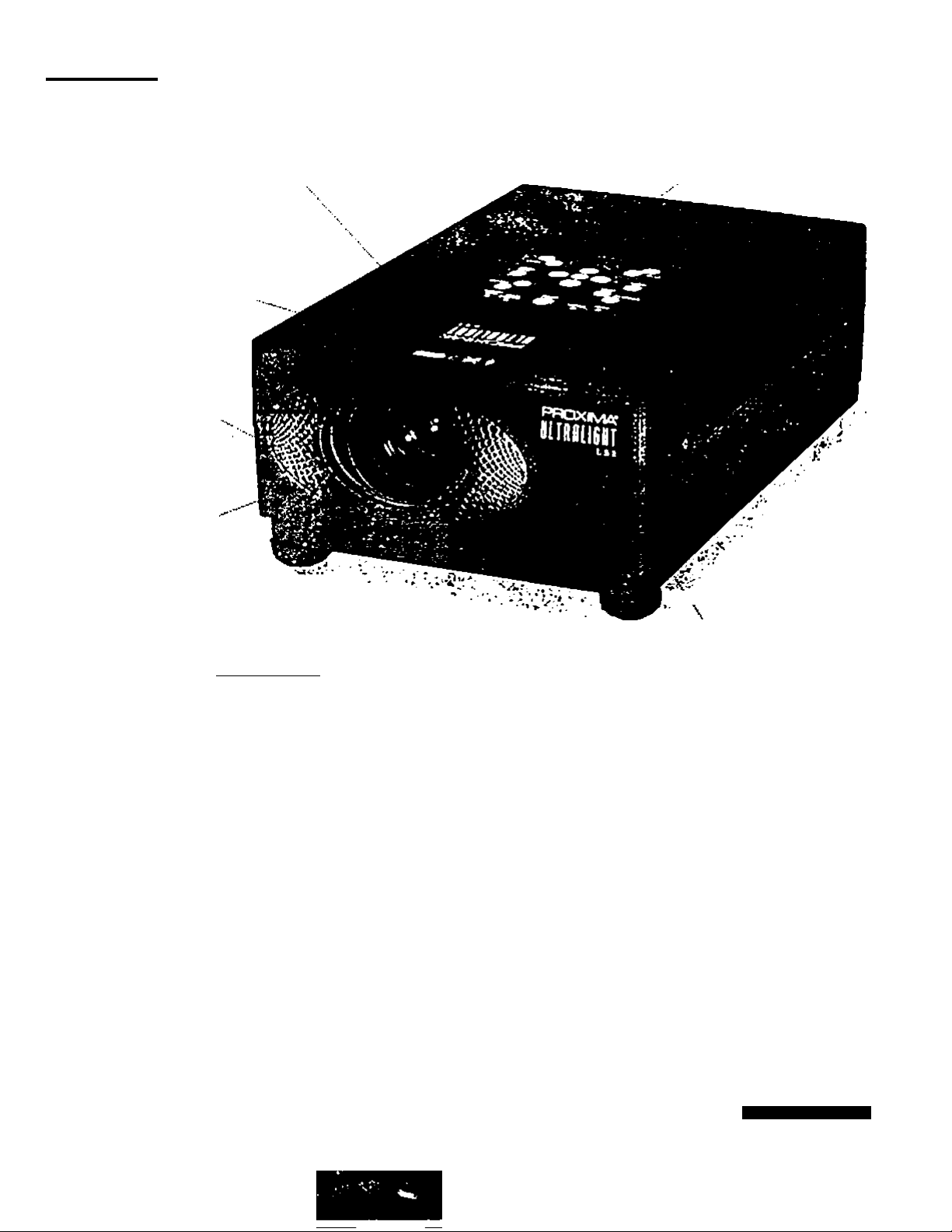
ULTRALIGHT LSI
To have the winning edge in your next presentation, look to the Proxima Ultralight LSI
mutiimedia projector. Selected by PC IVortf editors as the Best Projection System of '99, the
LSI offers big-projector features in a small, affordable package. You can count on the image
quality, set-up flexibilrty. and durability of the award-winning Ultralight LSI to ensure an
unbeatable presentation v^erever you go.
■ exceptional image quality with 700 ANSI lumens of brightness, for lights-on presentations
in any room
■ broad range of compatibility with PC desktops, portables, Apple Macs and PowerBooks
• supports full-screen images from any notebook with VCA1640 x 480). SVGA (800 x 800)
or X6A (1024 X 768) resolution
• magnesium alloy enclosure is both lightweight and extra durable, so it stands up to the
rigors of the road
• 1.6:1 power zoom lens allows you to set up the LSI anywhere in the room and adjust the
image size accordingly
• Proxima's Laser F/X^ remote control with buih-in laser pointer and mouse contrtM puts
you in command of the projector and your computer
LASER F/XREMOTE CONTROL
putt you in comrol of vovr
proitctof end your computer
PROXIMA*
MULTIM80IA PhOjecrOAS
WOfUO ClASl
8m1 PfOitcUoA Syitcm
DhOI
Page 2
I
к
ï
tV’
Г‘
» ?
ç;
[:•
St
I
II
- ltl§ll
* « M Í*ií
" Í|И<П
и ï i IJss I
■- Idilli»!
9
Щ
U
iU
il*
^ • I
62 I
ill
s
6
P
<
ж
s
oc
о
о
Z 2
•W ж
« I
ш ^
О 2
« S
4
î^ii.
lysiia:
il
II
f*
к
nil
4Ь V
liil
>•
«A
«
Ol
A
E
«•
«
w
e
A
e
о
1
SiSIS
bV».
Sis
s I
6; 6| 6
« ;
bis
f
Й
!3
•*S
9
Д
9
a
s
Ç
.0
«I
Sv»
3g
c
W
si I i! !
f 5 il I
di 18 1! Î
ilj
H
P
!-,
m1
Pili
Ili*
lift
Page 3
---
• . .-^ -Wftl
PROXliVlA*
ULTRALIGHT LS1
USEFTSGLUDE
3
PRESENTATIONS
WORKING SESSIONS
TRAINING
MULTIMEDIA
ANIMATION
VIDEO
Page 4
INFORMATION TO THE USER
NOTE: This equipment has been tested and found to comply with the limits for a Class A digital device, pu’^u
to Part 15 of the FCC Rules. These limits are designed to provide reasonable protection against
interference when the equipment is operated in a commercial environment. This equipment ger>.ji ^
uses, and can radiate radio frequency energy and. if not installed and used in accordance with the use
guide, may cause harmful interfererKe to radio communications. Operation of this equipment ir
residential area is likely to cause harmful interference in which case the user will be required to corr
the interference at his own expense.
TO THE OWNER
c
As the owner of a ULTRALIGHT LSI. you are probably eager to try out your new projector. Before you do,
suggest that you spend a little time reading this guide to familiarize yourself with the operating procedures.
Uvit you will receive moximum eatlefaction from the many features included in your new projeetor
This user's guide will acquaint you with your projector’s features. Reading it will help us too. Through the yea
we have fourtd that many service requests were rtot caused by problems with our projectors. They were caus
by problems that could have been prevented, if the owner had followed the Instructions in the guide.
You can often conoct operatir>g ^oblems yourself. If your prelector fails to work properly, s
TROUBLESHOOTING’ section on pages 47 - 46 and try the solutiorts marked for each problem.
SAFETY PRECAUTIONS
c
WARNING:
TO REDUCE THE RISK OF FIRE OR ELECTRIC SHOCK. DO NOT EXPOSE THIS APPUANCE TO RAIN (
MOISTURE. ^
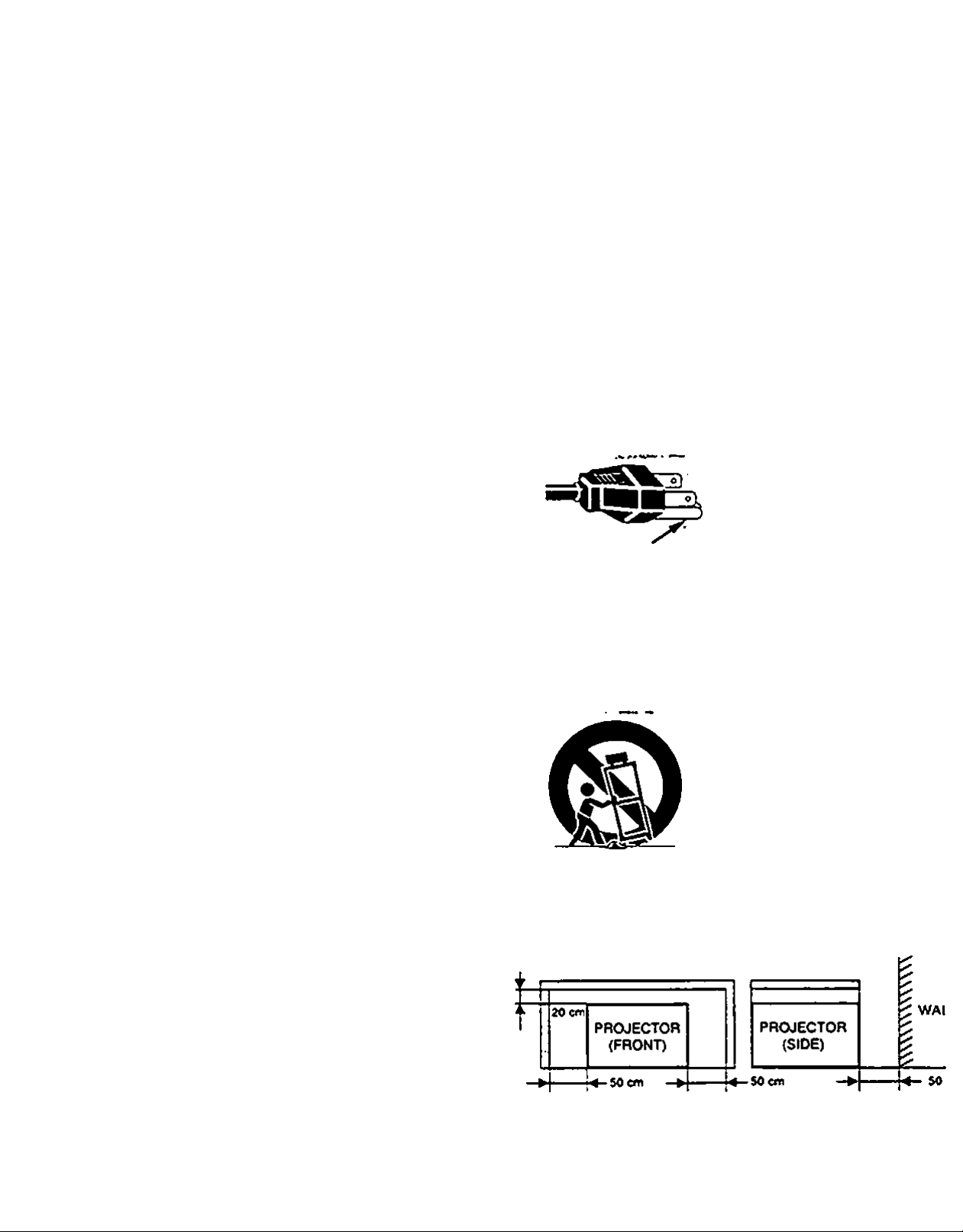
This Projector has a groundlng*type AC line plug. This is a safety feature to be sure that the plug'wiai
into the power outlet Do not try to defeat this safety feature.
Intense light source. Do not stare directly Into the projection tens as possible eye damage could resi
Be especially careful that children do not stare directly into the beam.
If the Projector will not be used for an extended time, unplug the Projector from the power outlet.
READ AND KEEP THIS USER’S GUIDE FOR LATER USE.
CAUTION
RISK OF ELECTRIC SHOCK
DO NOT OPEN
ISK pFtEUECTRlCrSHOCkrpOiNp^REMOy^
- •‘::•.VTTOSSYMBOLlNDlCATESJHAT-DANGER•‘•
ObS:.VOCfAGEOONSTПUTING A R1SKOF5
EEECTRICZSHOCK;iST»RESENr WTTHIN
THIS UNIT. "
^^•^^.TOSISYMBOLJNOICATES THATTHEHE ARE
IMPORTANT OPERATING AND MAINTENANCE
INSTRUCnONSTNTHE USER'S. GUIDE WTTH
THISUNFT.' .
.’JÔ
^2 —
Page 5
c
>
IMPORTANT SAFETY INSTRUCTIONS
All №« safety and oparadnd inam^cDona should be read
before the product ia operated.
Read ai of the instn>ctiond giveo here and retain them for
later use. Unplug (his proiector from AC power supply before
cleane>g. Do rtot use Squid or aerosol ciearvers. Use a damp
cloth for cleaning.
Oo rKt use attachmems not recommer>ded by the
fnaixdactuier as they may cause hazards.
Oo r>ot place this proiector on an unstable cart stand, or
table. The protector may M. causing serious infury to a cMd
or adult. ar)d sencus damage to the protector. Use only with a
cart or stand recommer>ded by the manufacturer, or sold with
the projector. WaN or shelf mounting should follow the
manufacturer's instructions, and should use a mounor>g kit
approved by the manufacturer.
Oo not expose this urvt to rain or use r>ear water... for
example, m a wet basement rvear a swimmmg pool. etc...
Slots and oper)ings m the back and bottom of the cabinet are
provtded for ventsation. to insure reliable operation of the
equipment and to protect it from overheating.
The opamr^ should r>6ver be covered with cloth or other
material, and the bottom opening should not be blocked by
placing the projector on a bed. sofa, rug, or other similar
surface. TNs protector should never be placed near or over
a radiator or neat register.
d. If the protector does not operate normally by following the
operabng instructions. Adfust only those controls that are
covered by the operating instructions as improper
adaistmem of other controls may result in damage and wfl
often require extensive work by a quaiiSed technician to
restore the projector to normal operation.
e. tf the projector has been dropped or the cabinet has been
damaged.
f. When the projector exhMs a distinct cha/>ge in
pociormance*this indicates a need lor service.
When repiacemem pans are required, be sure the service
technician rtas used replacement pans specified by the
manufacturer that have the same chs^actensocs as the
ohgjnal part Unauthorized substitutions may result in tire,
electric shock, or atfury to oersons.
Upon completion of any service or repairs to this protector,
ask the servKe techndan to perform routine safety checks to
determine that the projector is in safe operating condition.
This proiector is equipped with
a grounding type AC line plug.
Should yog be unable to insert
the plug into the outlet contact
your electrician. Oo not defeat
GROUND
Follow al warnings and instructions marked on the
profeetors.
the safety purpose of this
groundmg type plug.
This pro^ecw should not be placed in a budt*in instaHabon
such as a bookcase unless proper ventfation is provided.
This protector should be operated only from the type of
power source indicated on the mahor>g label. If you are not
sure of the type of power suppsed. consult your authonzed
dealer or local power company.
Oq not overload wall outlets and extertsion cords as this can
result in fire or eiecmc shock. Oo rtot allow anythir>g to rest on
the power cord. Oo not locate this projector where the cord
WIN be abused by persons waJidr>g on it
New push obiecu of eny kind into thie proi«cter through
cabinet slots as they may touch dangerous voltage points or
short out parts that could result in a fire or electric shock.
Never spiH liquid of any kind on the protector.
Oo not attemot to servM this protector yourseff as opening or
removing covers may expose you to dangerous voltage or
other rtazards. Refer all servtcing to quabfied service
personnel.
Unplug this projector from wall outlet and refer servicing to
quakited service personnel under the fosowng conditions:
a. When the power cord or plug is damaged or frayed.
b. If Bqud has been soded into the pr^ector.
c. If the projeaor has been exposed to rain or water.
For added protection to the projeaor during a lightnir>g storm,
or when It Is left unattended and unused for long periods of
time, unplug it ffom the was outlet. This wiH prevent damage
due to bghtning and oowenine surges.
An appliance and can combination
Should be moved with care. Oukk
stops, excessive force, and
uneven surfaces n\ay cause the
appiiarKo and cart combination to
overturn.
H the projeaor is to be built into a compartment or simiiarty
enclosed, the minimum distances must be maintained.
Do not cover the ventilation slot on the projeaor.
Heat buikl*up can reduce the service life of your projeaor.
and can also be dangerous.
-.3 —
Page 6

с
TABLE OF CONTENTS
PAGE
FEATURES AND DESIGN
ACCESSORIES 6
POWER REQUIREMENTS 6
DESCRIPTION 7
SETTING-UP THE PROJECTOR 6-9
POSmONING 8
ROOM UCKT
VENTILATION
AOJUSTABLEFEET
MOVING THE PROJECTOR 9 OTHER FUNCnON SETHNO
CONNECTINQ THE PROJECTORTHE 10-15
CONNECTING THE COMPUTER
MWop compufior eonApdJOfi 11 С>вп9
MpomoiA 4MM0P comput*^connocbon
l8M*«o«np4M)l4 lipioppomputorcoooocoon
M4amo»A PowpiSock <omput*r ewnecbon
CONNECTING THE VIDEO EQUIPMENT 15 TEMPERATURE WARNING INDICATOR
CONNECTING THE EXTERNAL AUDIO EQUIPMENT 15
OPERATION OF CONTROLS 16-18 CLEANING THE LENS
TOP OF THE PROJECTOR
REAR OF THE PROJECTOR
OPERATION OF REMOTE CONTROL 19-21
REMOTE CONTROL BATTERY INSTALLATION 21
USING REMOTE CONTROL 21
CONTROL THE PROJECTOR
DIRECTOPERATION
MENU OPERATION
8ASIC OPERATION
TURNING ON THE PROJECTOR 2S
TURNING OFF THE PROJECTOR 25
DIRECT OPERATION 26
MODE SELECT 26
SOUND VOLUME ADJUSTMENT 26
SOUND MUTE FUNCTION 26
ZOOM ADJUSTMENT 26
FOCUS ADJUSTMENT
NORMAL PICTURE FUNCTION 26
BLANK FUNCTION 26
FREEZE PICTURE FUNCTION
AUTO IMAGE FUNCTION
MENU OPERATION
MODE SELECT
SOUND ADJUSTMENT
LANGUAGE ADJUSTMENT 28
5 COLOR SYSTEM SELECT {V«440|
PICTURE IMAGE ADJUSTMENT (Vid«o>
PICTURE SCREEN ADJUSTMENT <Vd#o)
COMPUTER SYSTEM SELECT
PICTURE IMAGE ADJUSTMENT (Compulw)
PICTURE POSITION ADJUSTMENT (Compul4/|
8
6 AUTO IMAGE FUNCTION (Conwtor|
9 PICTURE SCREEN ADJUSTMENT {Compir)
10-14
12
13
14
16-17 TROUBLESHOOTINQ
AIR RLTER CARE ANO CLEANING
LAMP REPLACEMENT
PC ADJUSTMENT
Blu# ввек
CkBpèty
RMf
LAmpA^B
18 TECHNICAL SPECIFICATIONS
22-24
22
23-24
25-44
26
26
26
27-44
27
28
29
30
31
32*2
34
3$
36-3
40
41
42-4
42-4
42-4
42-4
42-4
42.4^
45
45
46
47
i ‘
~4~
Page 7

с
FEATURES AND DESIGN
This ULTAAUGKT LSI is ^signed me most edvanced technetogy for portaOiirty. dgreotlity. and ease
of use. The projector uolizes muiomedta features, a palette of 16.77 rmllton colors, and active
matnx bQuM crystal display (LCD) lecrmoiogy.
Compatibility
This proiecior is compaotle with many different types of personal computers and video
devicas. incfc>dir>9:
SVGA (600 X eOO). VGA (640 x 460.720 x 400.640 x 400)
MAC tr (S12 X 084). ir (640 x 460). 1Г (8Э2 x 624)
XGA (1024 X 766)*/MAC I9*(t024 x 766)* •*projected with congress mode
Various video eouipments using any of the world wide video standards,
including: NTSC. NTSC4.43. PAL and SECAM.
Image ffesolutlon
Picture Imape is profectsd in the resolution of 604 x 604. Screen resoiuttons between 600 x
600 and 1024 X 76$ are compressed to 604 x 604.
ТЫ$ protector cannot dttpiay in the resolution more than 1024 x 766. If your computer's
screen resoluPon is higher than 1024 x 766. reset the resolution to the lower before
connecting the pr^ector.
Portability
This profector is extremely corrpact m size and weight Havmg a sophisticated shape ttce
an atiachd case wrth a retractable carrying handle, the proiector ww help you make powerful
preser.tabon wherever you go.
Serean Mode
Screen display can be selected among;
Computer mode True, Digital zoom (Expand. Compress. Panning)
Video mode — Regular (4:3). VAde (16:9)
Multilanguage
MENU DISPLAY is displayed with:
Engtish. Oeutsch. Frartçad. itaOane. EspanOl. or Japanese
Automatic Multlscanning system
This protector can detect discUy sagnais from most personal computers currently
distnbuted. It 1$ free from compaeaied adjustments to project ptcture xnages from PC.
Motor Zoom / Focus Lens
Zoom and Focus of Lens can be controlled with Top Control and Remote Control.
Other Features
Reverse Display. Air Pad Remote Control
— 5 —
Page 8
с
ACCESSORIES
ТЫ$ projector containe ioloww>g parts. When unpacking, make sure aK of the parts listed oeigw ar* *
ir>cSuded. If any part is missing, contact authonzed dealer or service station.
• User's Oiade.
• AC Power Cords (UL and European types).
• Remote Control Unit ar>d Pattenes.
• Lens Cover.
• Canying case.
• VGA Cable.
• y/QAMAC Adapter.
• Mouse Cable for PS/2 port
• Mouse Cable for serial port
• Mouse Cable for A08 port.
• S*v»deo cable (Mini OiN^a type).
• АУсаЫе (RCA type ж 3).
• PC audio cable (Stereo mini )aek).
С
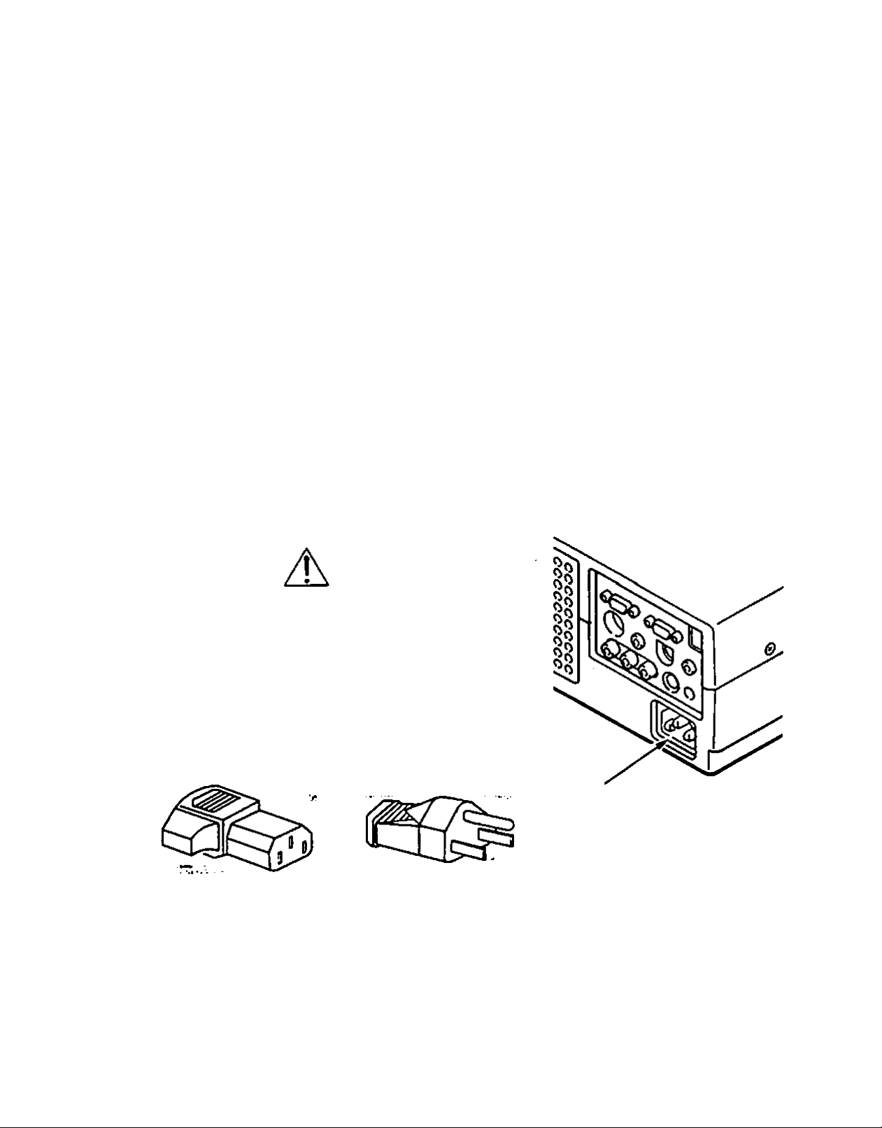
Your protector uses nominal input voltages of 100*120 VAC or 200*240 VAC. The projectc
automatically selects the correct input voAage. It is designed to work with single*phase pow(
systems having a grounded neutral conductor. To reduce the nsk of electncal shock, do not plu
into any other type of power system.
Consult your authorized dealer or service station if you are not sure of the type of power suppi
beir>g in use.
For the safety, unplug the AC Power
Cord when the appiance is r>ot
used.
When this projector is connected to
the outlet with the AC Power Cord,
the appliance is in Stand-by Mode
and consumes a little electnc power.
Projector side (Female) AC outlet side (Male)
POWER REQUIREMENTS
CAUTION
Connect the AC power supply cord (provided)
to the projector.
The socket-outlet must be near this equipment
and must be easily accessible.
TRADEMARKS
• Apple. Macintosh, and PowerSook are trademarks or registered trademan<s of Apo^ Computer, tnc.
• IBM and PS/2 are trademarks or registered trademarks of rntemaoonal Business Machines, inc.
• Pronma t$ a registered irademark of Proxima Corporation.
• 09>er trademarks are the property of their respective owrters.
— 6 —
Page 9
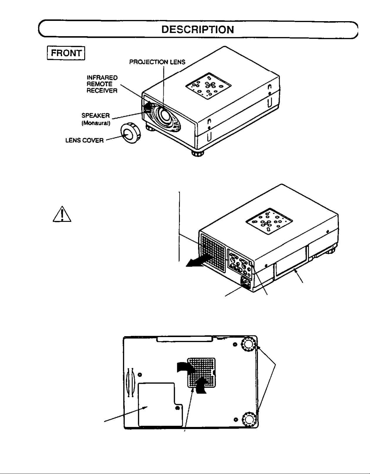
REAR
©(HAUST VENT
CAUTION
1
HOT AIR EXHAUSTED !
>
Air blown from the exhaust vent is hot
When using or Installing the projector.
following attention should be taken.
• Oo not put a flammable object near this part
Keep heat'sensitive objects away from the
exhaust part
• Oo not touch this part especiaily screws ar>d
metallic parts. This part will become hot while
the projector is used.
POWER CORO
CONNECTOR
CARRY HANDLE
INFRARED
REMOTE
RECEIVER
BOTTOM
ADJUSTABLE FEET
LAMP COVER
AIR INTAKE
VENT
— 7 —
Page 10
с
SETTING-UP THE PROJECTOR
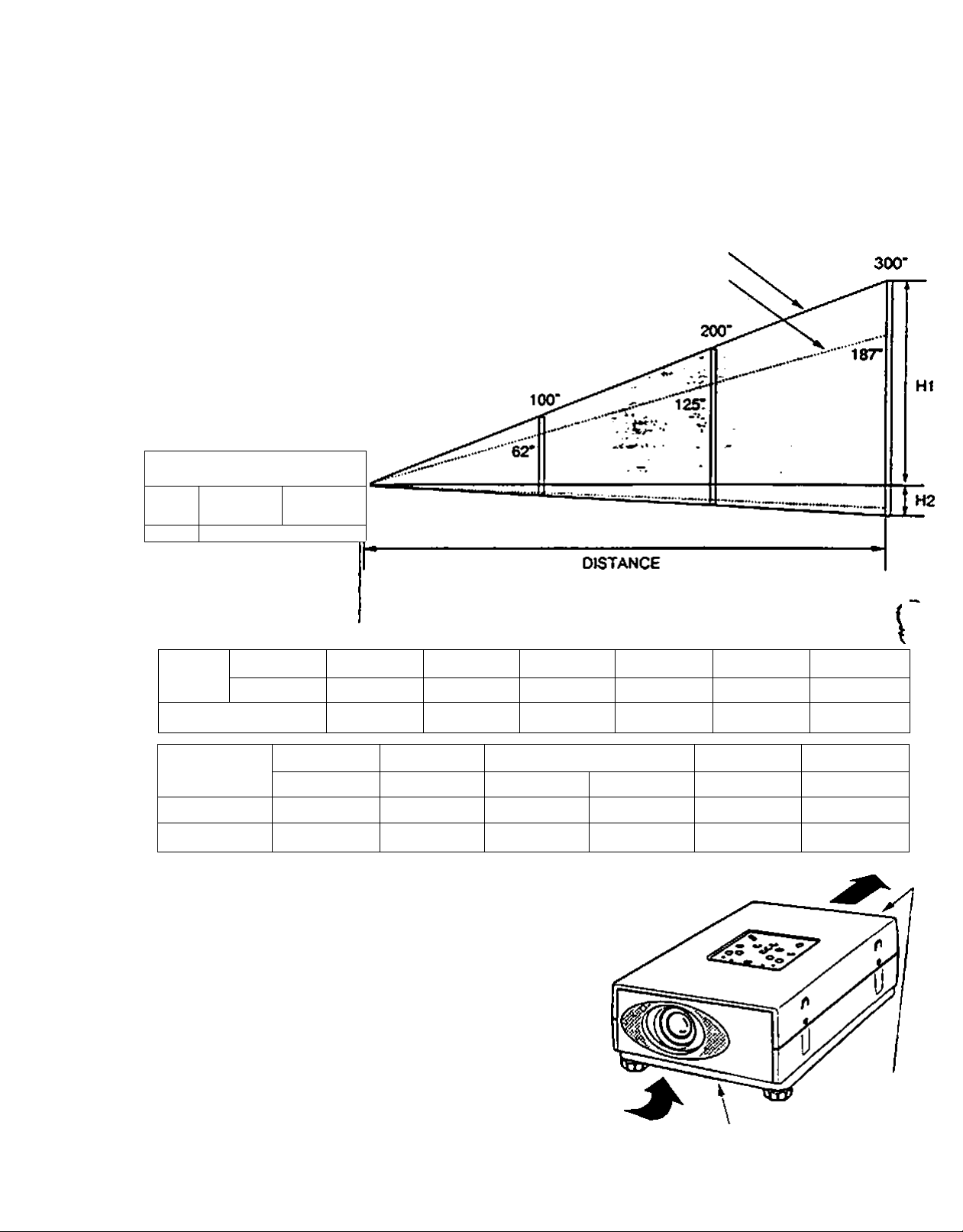
POSITIONING:
*TI«» pfujecCot is basicdlly dtssiyiwO (u piuj«№l on a (Idt piuii«ct>w«i surface.
• This projector can be focused from 3.6' (1.1 m) - 37.7* (11.5m).
e Refer to the figure below to adjust the screen size.
ROOM LIGHT
The brightness of the room has a great
influence on the quality of a picture. Dimming
the feghts can improve picture quality.
л:
____
Maximum Zoom>
Minimum Zoom
SCTMO
Size
Oietance
Screen Size
(W ж H) inefies
He^hi (HI)
He*9ht (H2)
Меж. Zoem
Mm. Zoom 18*
2СГ
16 X 12
n.4*(290mm) 34* (864 mm)
o.e'osnw)
29*
З-в* (l.t m)
49 X 36 80X 60 120 X90 I60X 120
2* (50 mm) Г(7втт) 4* (102 mm)
w
ЗГ
7.5* (2.3 m) 12.S* (3.8 m)
ecr 100* 1 ISO*
57* (1448 mm)
100*
VENTILATION
This projector is equipped with coofing fans to protect it from
overheating. Pay attention to the foAowing to ensure proper
air flow and avoid possible risks of fire and malfunction.
Do not cover the vent windows.
Keep the rear grill at least one meter away
Ж
from any object
Make sure that there are no object uiyfer the
projector. An obstacle under the projector may
prevent the projector from taking the cooling air
through the bottom vent
er
15<r
93-
iar(5.7 m) 24.9' (7.6 m) 37.7- (it.Sm)
86* (2184 nvn)
114* (2896 mm) 171* (4343 mm)
AIR INTAKE VENT
(BOTTOM SIDE)
200* 300*
125*
200* Э00*
6" (152 mm)
ler
240X 180
9* (229 mm)
exHAusi
(REAR SIDE)
Page 11
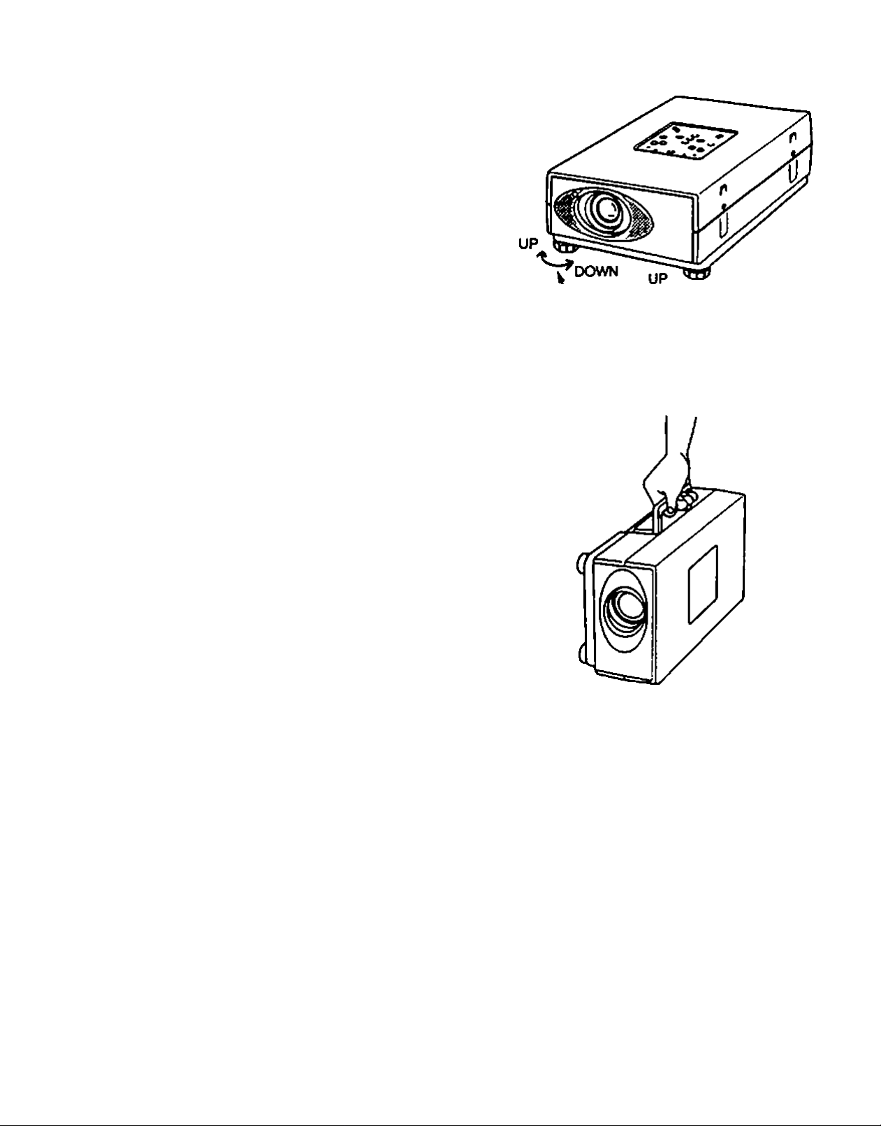
adjustable'Feet
Picture tilt and protection angle can be adjusted by twisting
ADJUSTABLE FEET. Protection angie can be adjusted 0 to
2* by rotating adjustable feet
D
XT
C
Use the carry handle when nxiving the projector.
eWhen moving the projector, replace the lens cover and
rotate the feet fully clockwise (to shorten the feel) to
prevent damage.
MOVING THE PROJECTOR
DOWN
ADJUSTABLE FEET
:
A
• Do not dr^ or give a shock to the projector, otherwise damages or malfunctions may result
• When carrying the projector, use a Proxima recommended carrying case.
• Do not transport the projector by using a courier or transport service in an unsuitable transport case. This may
cause damage to the projector. To transport the projector through a courier or transport service, use a Proxima
recommend^ case.
• For a carrying or transportation cases, contact a Proxima authonzed dealer.
CAUTION IN CARRYING OR TRANSPORTING THE PROJECTOR
— 9 —
Page 12

c
CONNECTING THE PROJECTOR
This projector has various kir)d of input/output terminals to connect with peri;
equipment. Connect the projector to the equipments before turning it on.
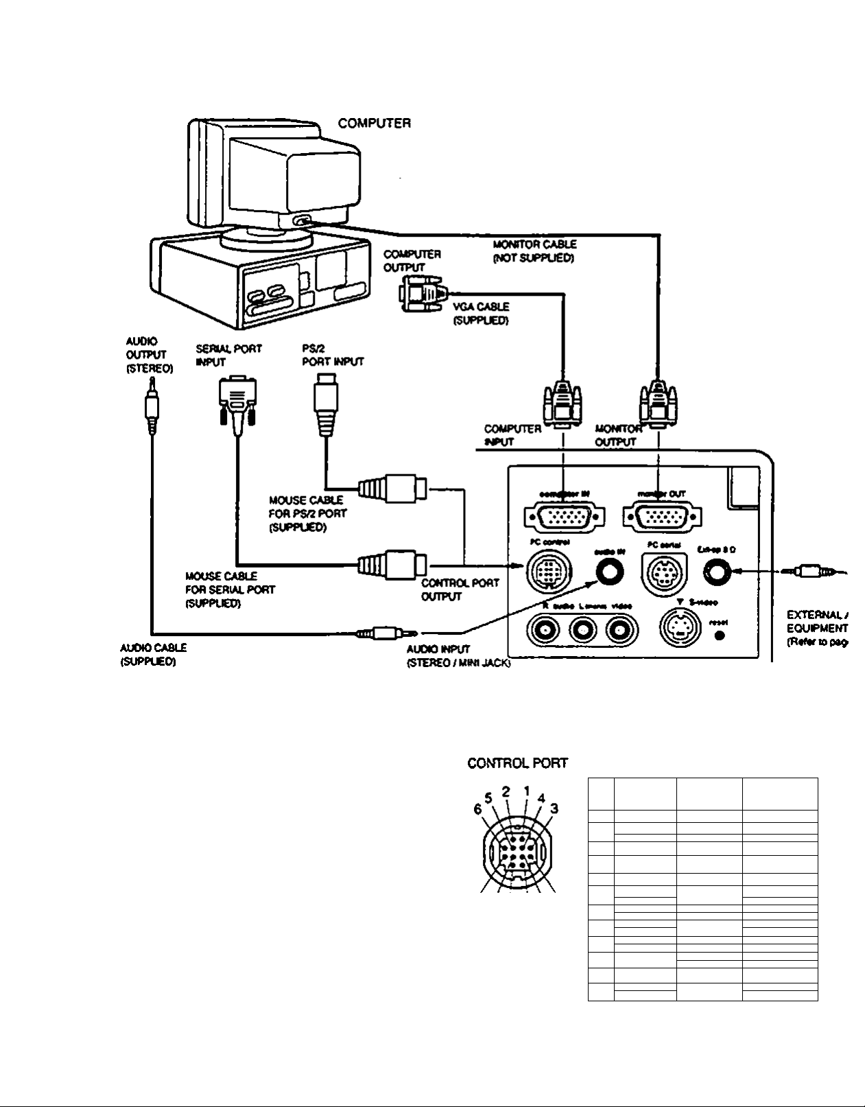
CONNECTING THE COMPUTER
CONNECTINQ TO THE COMPUTER INPUT HDB15-PIN fVGA) TERMINAL
A computer can be connected to the HOBtSpin terminal on the protector.
• Connect the computer to this terminal using the VGA cable and VGA/MAC adapter
(suppfied).
CONNECTING TO THE MONITOR OUTPUT HDB1S»PIN (VGA) TERMINAL
This terminal outputs only computer input signal to the monitor.
A monitor can be connected to the HDBlS-pin (VGA) terminal on the projector.
• Connect the monitor to this terminal using the monitor cable (not supplied).
CONNECTING TO THE COMPUTER AUDIO INPUT JACKS
• Connect audio outputs from your computer to the jacks using №e audio cable.
•1
t *-
^ 0
CONNECTING TO THE MULTNPOLE 12»P1N (CONTROL PORn
I If you wish to control the computer with projector's remote control unit, you must conrt
the control port (PS/2. Serial or ADB port) on your computer to the projector's control Pv. i
with one of the suppled cables, (three type cables provided: for PS/2 Port. Serial Port ane
A08 Port)
CONTROL PORT CABLE REMOVAL HINT
Disconnect control port cable with foHowing steps.
t. Hold the portion (A) of the connector with one hand.
2. Pull the portion (8) arrow direction and remove
coooector.
CONNECTING TO THE DIN 8 (SERIAL PORT) CONNECTOR
I If you control the projector by computer, you must connect a cable from your computer to
this connector.
1.
^ ri. j;;
^2
r\
A Y
Í
3 J ^
tA 'S
/
Page 13
IBM-compatible desktop computer connection
]
NOTE :VmenecmecQngl^e cable, irte powsrcordsof bottihe protector and me exiemaiequcmenteshouid be dtsconneewdfremACouseL
Tum me proieeier and penpherai equiprnems on betore me ccRtpucer is swticned en.
IK08 1$-PIN TERMINAL
(COMPUTER INPUT / MONITOR OUTPUT)
i 4 i 2 t
e e e e e
10 e e 7 6
o o o e I
i O O O O O
Vis 14 13 13 11
PinNo./Signai
1 Raairw
2 o^mcu
0
4 $0fmt
5 (Vound (Hm.iyne.)
$ OrOMHd (R4d|
7 QfOiM
P«iNo./&gn«J
$ NonCCfVM
10 (V^tyrK }
ti s«r»40
12 S«r*0i
10 Hónz.$fric-
14 v*a tync.
1$ R444<V00
$ 0^4^ 431U4)
10^^ M
9i2 11 8
PS/2
*í*
Port
1
:2
'9
4 GND
8
• READY
r
•
$
OATA
10
11
CLK
13
SoHol
Port
ONO
R>D
T*0
ADB
Port
GND
ADB
— 11 —
Page 14
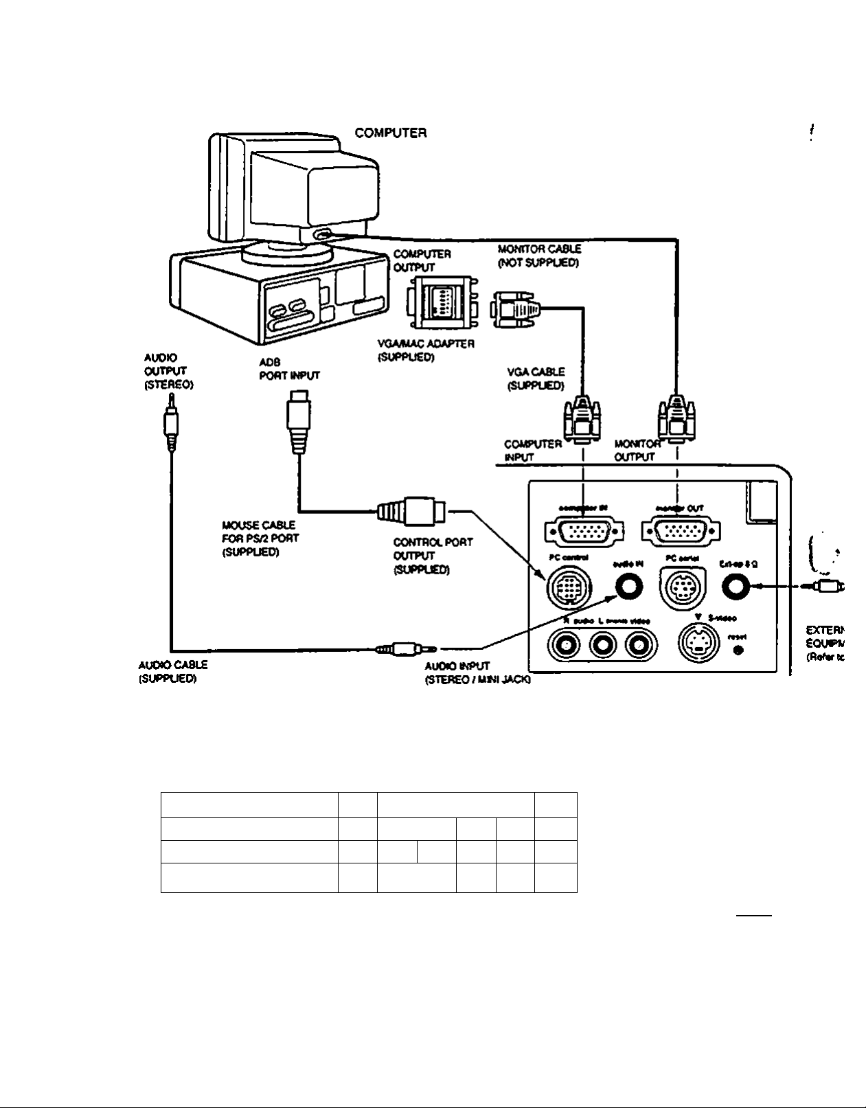
Macintosh desktop computer connection
Set the s&de switches as shown in the taMe below depending on
the RESOLUTION MODE that you want to use betöre you turn on
the projector and computer.
RESOLUTION MODE SW1
13* MODE (640 X 400)
16’MODE (832X624)
19" MODE (1024 X 768)
ON
OFF, ON OFF ON
OFF
SW2
SW3|SW4|SW5
ON
ON ON OFF
OFF
OFF OFF
SW6
OFF
OFF
OFF
OFF OFF
SW1-SW6 .
ON \ C
B
'OFF
---------
VGAMAC ADAPTER
J In
Ok D<a
mm
!
mil III mm
NOTE: When ccooecwgihecaM.n« power cores of Dom vie prcjecwr and (he extemaf eowpmerfts should be Oeconrtected from A«'
Tun Vie proiecicr and peripheral eqi*pments on ceicre the computer eswnened on.
— 12 —
j
Page 15
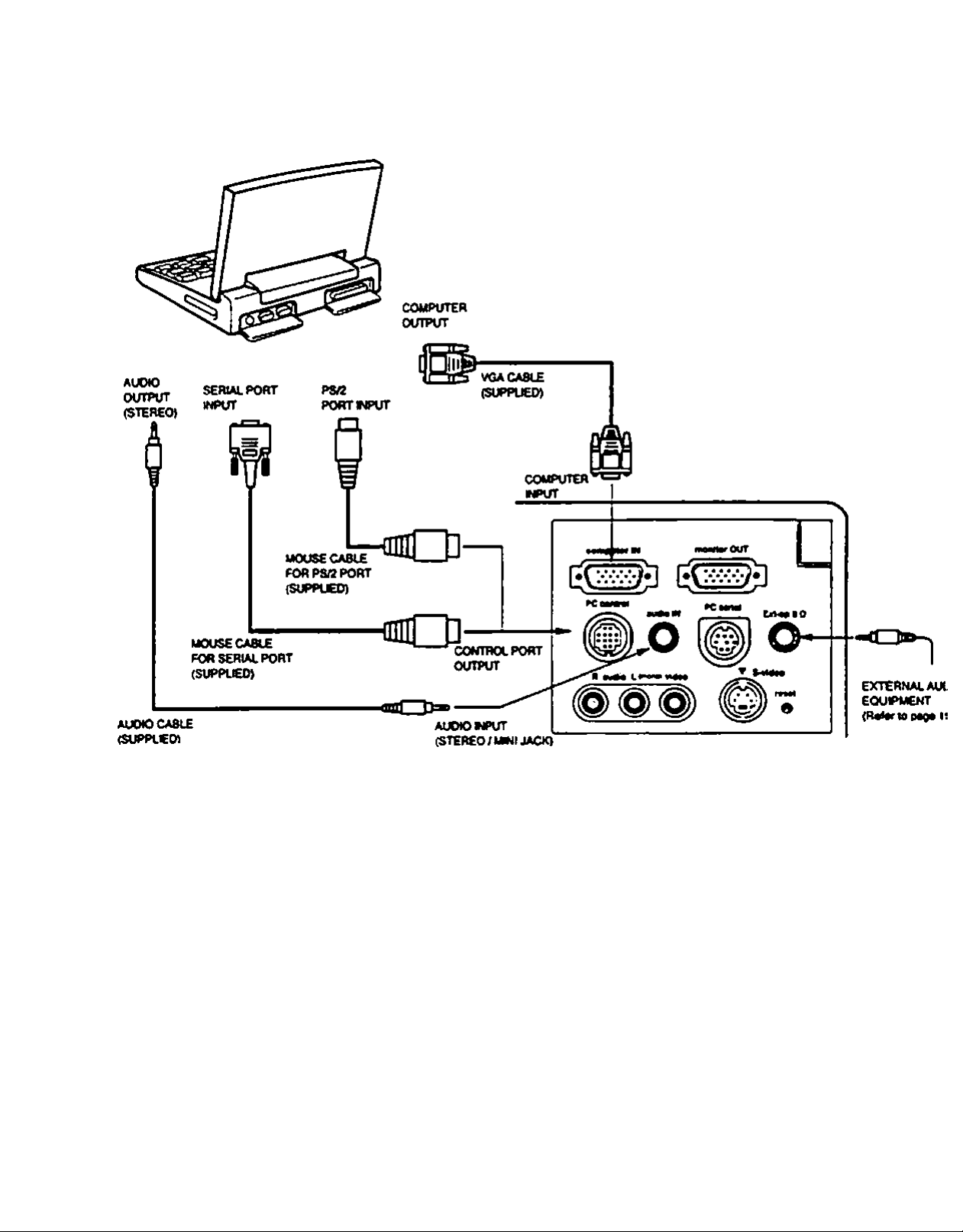
IBM-compatible laptop computer connection
COMPUTER
NOTE . caM. me poMV cords c< bomm«prcfec(oran4thssxtsrnilsquipmoctssno^bodisconn#aedCromACo<Mt
the profoaoriod ponphsrai oqmpmenes on boforo (ht computsr« rMtchtd oa
— 13 —
Page 16

Macintosh PowerBook computer connection
COMPUTER
Set the'sKde switches as shown in the table below depending on
the RESOLUTION MODE that you want to use before you turn on
the projector and computer.
RESOLUTION MODE SW1
irMODE (640 X 480)
16“ MODE (832 X 624)
19“ MODE (1024 X 768)
SW2 SW3 SW4|SWS|SW6
ON ON
OFF ON
OFF
OFF OFF OFF 1 OFF
OFF ON 1 OFF 1 OFF
ON ON OFF OFF OFF
I
-o
£Xr&V
EQUIPK
VGA/MAC ADAPTER
NOTE: When ccnnee^ the cabe. the power cords of beet the prctectcr and the external equpfrem should be dtsconnected from AC oom
Tt^theproiecscrandpenpheni edutprrents on before the computer esv^^ched on
^ 14 ^
Page 17

CONNOTING THE VIDEO EQUIPMENT
CONNECTING TO THE AUDIO/VIDEO INPUT JACKS
Connectng to the video and audio outputs ot a VCR. video disc player, video camera, satellite
TV tuner or other Video equipment
• Connect audkVvideo outputs from external source to these input jacks using the
audioA/ideo cable.
• If the audio signal from the Video equipment is stereo, be sure to connect the right and left
channels to the respective right and left audio input jacks.
• If the external audio signal is monaural, connect it to the L (MONO).
S»VHS FORMAT VCR CONNECTION
The Video input includes an extra video input jack marked S-VIDEO to aJkiw connection to an
S-VHS format VCR that has separate Y/C video sigrtals. The S-Vl^O jack has priority over
the VIDEO jack.
CONNECTING THE EXTERNAL AUDIO EQUIPMENT
CONNECTING TO THE AUDIO OUT JACK (mini stereo type)
This jack outputs stereo sound from video or computer mput when viewit>g on screen. If you
use external audio equipment, connect an audio anrtpifier. Internal speaker sound is retained
when AUDIO OUT jack is connected.
1
Video and External Audio Equipments connection
Connect equipments referring trie figure betow.
VIDEO EQUIPMENT ’
I Video Cassette Recorder VWeo Oise Player sateNrte
I
L
ii
TV Tuner
— IS —
Page 18

c
OPERATION OF CONTROLS
TOP OF THE PROJECTOR
TOP CONTROL
TOP
CONTROL
(
d O
— te —
Page 19

A UMP POWER INDICATOR
Light is dim when the protector is on.
Light is bnghtened when the projector is in stand-by mode.
A READY INDICATOR
Light is green when prqector lamp is ready to be turned on.
TEMPERATURE WARNING INDICATOR
e
Flashes red when internal projector temperature is too high.
A LAMP REPLACEMENT INDICATOR
Light turns to yellow when the life of a projection lamp draws to an er>d.
A POWER ON/OFF BUTTON
Used to turn projector on or off.
A COMPUTER SELECT BUTTON
Used to select computer mode.
VIDEO SELECT BUTTON
Used to select video mode.
A VOLUME BUTTONS
Used to adjust volunne of sound.
MENU BUTTON •
©
This button is used to call MENU operations. (MENU DISPLAY is displayed on the screen.)
1
II AUTO IMAGE BUTTON
<E>
Used to operate AUTO IMAGE function.
ZOOM BUTTONS
Used to operate power zoom lens.
FOCUS BUTTONS
Used to operate power focus system.
POINT UP/DOWNA^FT/RIGHT BUTTONS *
0
Used to select an item on MENU. To select an item, move through the menu by pressing these buttons (UP.
DOWN. LEFT or RKSHT).
These buttons are used to operate panning mode in Picture Screen Adjustment of Menu Operation. (Refer to
Page 4i for Picture Screen Adjustment.)
SELECT BUTTON •
0
Used to activate the item you want to adjust or change value up ^ down. This button is used to expand the ima{
in Picture Screen Adjustment of Menu Operation. (Refer to Page 41 tor Picture Image Adjustment)
* MENU. POINT UP^>OWN1£FT.9UOHT. «nd SEUECT dr* ut«d to on MENU OISPCAV. Rolor to
*MENU OPERATION'* on 27 to oporitd MENU DISPLAY.
Page 20

REAR OF THE PROJECTOR
COMPUTER INPUT TERMINAL
Ф
Used to connect a computer to the projector.
MONITOR OUTPUT TERMINAL
Used to connect a monitor to the projector.
CONTROL PORT CONNECTOR
Ф
Used to connect a rrNXJse port to the projector.
COMPUTER AUDIO INPUT JACK
Ф
(S^mm mini stereo type)
Used to connect a computer audio input
(stereo) to the projector.
PC SERIAL PORT CONNECTOR
Ф
Used to connect a computer to the projector.
AUDIO OUTPUT JACK <
0
(3.5 nvn mini stereo type) i
Used to connect an audio amplifier. \ ,
AUDIO INPUT JACKS
Used to connect an audio input to the projector.
S-VIDEO INPUT JACK
Used to connect a S-VHS v>deo source to t
projector.
VIDEO INPUT JACK
Used to connect a video source to the projector.
RESET BUTTON
1^ This projector uses Micro Computer control.
In the unlikely event that the Micro Comou
control fails to operates, press the RESET butt
with a small pointed object (like a pen) to St
down the protector.
— 18 —
Page 21

c
OPERATION OF REMOTE CONTROL
*^is remote control ur^it not only operates the profector but may
so be used as a wireless mouse for a PC. One joystick and four
jttons are used for wireless mouse operation.
The wireless mouse is active when the PC cursor is displayed on
tne screen. When me pro|ecior menu is displayed on me screen
instead of the cursor, the wireless mouse cannot be used.
NOTE: To use the unit as a PC wireless mouse, connect the
profector to the PC with the attached cable. Signals from
the projector are transmtted to the PC. enabling the remote
control unit to be used as a PC wireless mouse. (Refer to
■CONNECTING THE PROJECTOR* in pages 10 to 14 for
the connection.)
See caution when operating the Laser remote
□ANGER
“ OioMLaMf
0 Mifwao max ouipui
LASER RACHATION
DO NOT STARE INTO SEAM
Waviaoyft 690-e80 nm
Ctaas IMa lasf Product
control. Laser light can cause harm if projected at
the human eye. Observe the cautions on the Laser
Warning label located on the rear of the remote
control. Do not point the laser directly Into any
person’s eyes.
FRONT
REAR
— 19 —
Page 22

AUTO IMAGE BUTTON
Used to operate AUTO IMAGE fur\ction.
NORMAL BUTTON
e
Use to reset to normal picture adjustment preset by factory.
BLANK BUTTON
e
Used to change the screen into black image.
MENU BUTTON
This button will activate the MENU operation. Use this button, the POINT UP/DOWN/LEFT/RIGHT button and th<
SELECT button to make adjustments to the protector's setting in MENU operation.
LAMP POWER ON/OFF BUTTON
e
Used to turn the projection lamp on or off.
FREEZE BUTTON
©
Use this button to freeze on-screen image.
MODE BUTTON
Used to select video source. (Computer or >Adeo Input)
@ FOCUS BUTTONS
Used to operate power focus system.
VOLUME BUTTONS
©
Used to adjust volume.
ZOOM BUTTONS
(E)
Used to operate power zoom lens.
SOUND MUTE BUTTON
<D
Used to mute sound.
JOYSTICK
(POINT UP/DOWN/LEFT/RIGHT BUTTON)
When used as a renwte for the projector control. \
To select an item on the MENU that you want to adjust To select an item, move the arrow by move the joystick
forward, backward, left or right
When used as a wireless n>ouso
Acts bke a mouse. Move the joystick in the direction that you want to move the screen cursor. The further you
move the joystick in any direction, the faster the cursor will move.
SELECT (LEFT CUCK) BUTTON
When used as a remote for the projector control.
This button has different functions depending on when used. This button is used to select menu items.
When used as a wireless mouse
This button has the san>e function as the left button in a PC mouse.
RIGHT CUCK BUTTON
This button has the same function as the right button in a PC mouse. Pressing this button does not affect any
operation when in MENU mode.
DRAG LEFT/RIGHT BUTTONS
0
Use this button and the joystick to drag a selected screen object Press ar>d release the Drag Left or Right button,
the button glows and the remote control is in Drag mode. Move the joystick in the direction that you want to drag
the screen object. Press and release a second time to drop the object at the new screen locabon.
(
LASER BUTTON
0
Press arid hold to activate the laser pointer.
— 20 —
Page 23

REMOTE CONTROL-BATTERY INSTALLATION
USING REMOTE.CONTROL
* SlTde the batteries into the
2
- wmpartmanL-
Note: For correct poUrity (♦ and •
tenranat)« be sure the battery
tomwiale are in contact wrtn
the pets in the companmenL
Ropiace the compart*'
mentid.
3f
Point the remote control toward the projector’s front or rear receiver windows whenever using the rermte control.
Maximum operating range forthe remote control is about 16.4'(5m) and 60* front ar>d rear of the projector.
1
To insure sale operation, please observe the following precautions:
A
« Use (2) AAA type alkaline batteries.
• Change two batteries at the same time.
• Oo not use a new battery with a used battery.
• Avoid contact with water.
• Oo not drop the remote control unit.
• if batteries have leaked on the remote control, carefully wipe the case
clean and load new batteries.
— 21 —
Page 24

c
CONTROLLING THE PROJECTOR
This projector is controtled through DIRECT OPERATION, or through MENU OPERATION.
DIRECT OPERATION: The projector is controlled directly with the buttons on the TOP CONTROL or REMO.
CONTROL (Refer to Page 26.).
MENU OPERATION ; The projector is adjusted by operating the MENU DISPLAY. Press the MENU butUx
and MENU DISPLAY is activated.
DIRECT OPERATION
ADJUSTITEM
POWER ON/OFF'^’
. MODE SEUECrr ^2^.
i?j<ÈÌup.:vjA6iBe5i
SOUND VOLUME-' —“
SOUND MUTE Not available MUTE BUTTON
ZOOM
FOCUS FOCUS (♦) and (-) BUTTONS FOCUS (♦) and ( -) BUTTONS
\oRiyiAL PICTURE
BLANK . 1
FREEZE '
AUTO IMAGE
.
* «
#TOP CONTROL..
»OFTHE PROJECTOR
POWER ON-OFF BUTTON POWER ON-OFF BUTTON
COMPUTER BUTTON
VIDEO BUTTON
VOLUME (♦) and (-) BUTTONS
ZOOM (♦) and (•) BUTT<^S
Not available
Not available
Not available
AUTO IMAGE BUTTON
ii REMOTE CONTROL UNIT
MODE BUTTON
VOLUME Wand (-) BUTTONS
ZOOM (+) and (-) BUTTONS
NORMAL BUTTON (
BLANK BUTTON
FREEZE BUTTON
AUTO IMAGE BUTTON
— 22 —
Page 25

MENU OPERATION
} -
. -
ADJUST ITEM
TOP CONTROL -9: V T
OFTHE.PROJECTOR %
MODE SELECT ^
•?»iv
'.-лаа*
• •• ^ • •
.* - Л'/- •
. • #^A
MENU BUTTON
POINT LEFT/RIGHT BUTTONS
SELECT BUTTON
•• % .
1. COMPUTER / VIDEO MODE
ADJUST ITEM
SOUND
SOUND VOLUME
SOUND MUTE
LANGUAGE
SETTING
BLUE BACK
DISPLAY
CEIUNG '
REAR
LAMP AGE
7!tOP CONTROL .
;* OF-THE PROJECTOR •
MCMI 1 PI iTTAKI
POINT LEFT/RK3HT BUTTONS
SELECT BUTTON
PaNT UP/DOWN BUTTC^S
SELECT BUTTON
REMOTE CONTROL UNIT
•* . ..
MENU SUTTON
POINT (LEFT/RIGHT) BUTTON
SELECT BUTTON
'REMOTE CONTROL .UNrr
MENU BUTTON
POINT (LEFT/RIGHT) BUTTON
SELECT BUTTON
PaNT (UP/OOWN) BUTTON
SELECT BUTTON
2. VIDEO MODE
ADJUST ITEM
COLOR SYSTEM
PICTURE IMAGE
COLOR
TINT
CONTRAST
BRIGHTNESS
SHARPNESS
PICTURE SCREEN
REGULAR
WIDE
TOP CONTROL
OF THE PROJECTOR
MENU BUTTON
POINT LEFT/RIGHT BUTTONS
SELECT BUTTON
POINT UP/DOWN BUTTCXIS
SELECT BUTTON
MENU BUTTON
POINT LEFT/RIGHT BUTTONS
SELECT BUTTON
POINT UP/OOWN BUTTONS
SELECT BUTTON
REMOTE CONTROL UNIT
MENU BUTTON
PaNT (LEFT/RIGHT) BUTTON
SELECT BUTTON
POINT (UP/DOWN) BUTTON
SELECT BUTTON
MENU BUTTON
POINT (LEFT/RIGHT) BUTTON
SELECT BUTTON
PaNT (UP/DOWN) BUTTON
SELECT BUTTON
— 23 —
Page 26

3. COMPUTER MODE
ADJUST ITEM
COMPUTER SYSTEM
. > •%- ^»4w". . '
PICTUREIMAGE
ONE SYNC
TOTALDOTS
WHITE BALANCE
CONTRAST
BRIGHTNESS
PC ADJUSTMENT
AUTO IMAGE
FINE SYNC
TOTALDOTS
POSITION
PICTURE POSITION
TOP CONTROL
^ OF-THEPROJECTOR
MENU BUTTON
POINT LEFT/RIGHT BUTTONS
SELECT BUTTON
POINT UP/t>OWN BUTTONS
SELECT BUTTON
MENU BUTTON
POINT LEFT/RKaHT BUTTONS
SELECT BUTTON
POINT UPiDOWN BUTTONS
SELECT BUTTON
MENU BUTTON
POINT LEFT/RIGHT BUTTONS
SELECT BUTTON
POINT LEFT/RIGHTAJP/OOWN
BUTTONS
SELECT BUTTON
'¿R^OTECONTHOL-U
MENU BUTTON
POINT (LEFT/RIGHT) BUTTON
SELECT BUTTON
POINT (UP/DOWN) BUTTON
SELECT BUTTON
MENU BUTTON
POINT (LEFT/RIGHT) BUTTON
eci m n-r/Mii
OCLcW 1 DU 1 1
POINT (UP/DOWN) BUTTON
SELECT BUTTON
MENU BUTTON
POINT (LEFT/RIGHT) BUTTON
SELECT BUTTON (' ‘
POINT (LEFT/RIGHT/UP/OOU
BUTTON
SELECT BUTTON
PICTURE SCREEN
TRUE
DIGITAL ZOOM
MENU BUTTON
POINT LEFT/RIGHT BUTTONS
SELECT BUTTON
POINT UPjDOWN BUTTONS
SELECT BUTTON
MENU BUTTON
POINT (LEFT/RIGHT) BUTTON
SELECT BUTTON
POINT (UP/OOWN) BUTTON
SELECT BUTTON
Page 27

c
BASIC OPERATION
TURNING ON THE PR^JECTOR
1. Connect pofipheral equipment (Computer. VCR. and etc.) belore turning on the
projector. (Retef to *CONNeCTING THS PROJECTOR' on Pages 10-15 (or
connecting those equipments.)
2. Connect the AC power cord of the projector into a wall outleL Make sure READY
INDICATOR on TOP CONTROL turns to green, and LAMP INDICATOR turns to
red.
3. Press ON^F BUTTON on TOP CONTROL or REMOTE CONTROL LAMP
INDICATOR turns dim.
4. A number appears on the screen, and NUMBER counts down until picture image is
displayed. It’s takes about 30 seconds to project a image.
NOTE: Turn on the computer last when the computer is connected In system.
CAUTION
A
NOTE:When TEMPERATURE WARNING INDICATOR flashes red. the protector will automaticaly turn off.
THIS PROJECTOR USES A UHP LAMP. TO MAINTAIN THE UFE OF LAMP. ONCE YOU TURN IT
ON. WAfT AT LEAST 5 MINUTES BEFORE TURNING IT OFF.
Wait at least 5 minutes to turn the projector on again.
If TEMPERATURE WARNING INDICATOR conbnues to flash, follow the procedures below:
1. Press POWER ON-OFF BUTTON to OFF.
2. Check if the air filter is contaminated with dust. The air filter must be maintained and cleaned.
Refer to ‘AIR FILTER CARE AND CLEANING* on Page 45.
3. Press POWER ON-OFF button to ON.
If TEMPERATURE WARNING INDICATOR stll consnues to flash, call your authorized dealer or service
station.
TURNING OFF THE PROJECTOR
1. Press the POWER ON-OFF button on TOP CONTROL or REMOTE
CONTROL The message ‘Power off?’ appears on the screen.
2. Press again POWER ON-OFF button to turn the projector off. Make sure
LAMP INDICATOR turns to bright. READY INDICATOR turns off and the
cooling fans operate for 1 minute for cooling the projector after switched off.
(NOTE : During the cooling sequence the projector, cannot be turned on.)
3. When coofing of the projector is finished. READY INDICATOR turns to green
again. You can turn the projector on again.
Power off ?
— 25 —
Page 28

DjRECT OPERATION
MODE SELECTn-QP eontron
Press the COMPUTER or VIDEO button to select Computer or Video
mode.
MODE SELECT (Wireless remote control)
This function is operated with MODE button. MODE button is used to
select the input niode either Computer or Video. Setect the mode to
suit your input source. The 'Computer' or *N^00* display will appear
on the screen for a few seconds.
SOUND VOLUME ADJUSTMENT
Press VOLUME buttons (located on TOP CONTROL or REMOTE
CONTROL) to adjust the volume. The volume display wiN be displayed
on the screen for a few seconds.
Pressir>g volume ('*■} will increase volume and increase the number on
the screen.
Pressing volume (-) will decrease volume and decrease the number on
the screen.
SOUND MUTE FUNCTION
Pressing MUTE button on REMOTE CONTROL to cut off the audio
sound. Press the MUTE button ag^ to restore audio to its previous
level. The mute display will be displayed on the screen for a tew
seconds. External audio equipments produce the audio sound while
MUTE is on.
ZOOM ADJUSTMENT
- .Computer
^4 ' 'tW
ijKl Mute
gi[-:
32
~'| On
Press the ZOOM (♦) or (-) buttons (located on TOP CONTROL or REMOTE CONTROL)
to obtain your desired picture size. For a larger picture, press (♦) and (or a smaller
picture, press (-).
FOCUS ADJUSTMENT
Press the FOCUS (♦) or (- ) buttons (located on TOP CONTROL or REMOTE
CONTROL) (or a shan^. crisper picture.
NORMAL PICTURE FUNCTION
The normal picture level is factory preset on the projector and can be restored anytime
by pressing NORMAL button (located on REMOTE CONTROL). The 'Normaf display
v^l be displayed on the screen (or a few seconds.
BLANK FUNCTION
Press BLANK button on REMOTE CONTROL The screen will change into black image
and 'NO SHO^ is displayed on the screen for a few seconds. This function is cancelled
when BLANK button is pressed again or any other (unction button is pressed.
FREEZE PICTURE FUNCTION
Press the FREEZE button on REMOTE CONTROL, and the picture wil remain on-screen. This lunctioi
car>cel!ed when the FREEZE button is pressed again or any other function button is pressed.
NOTE: Your computer or video equipment is not affected by this function, and will ^bnue to run.
AUTO IMAGE FUNCTION
r-ZSoni
FÒCUS
Normal
' NaShow
Press AUTO IMAGE button on TOP CONTROL Of REMOTE CONTROL. The item(s) indicated 'ON'
IMAGE FUNCTION are adjusted automatically.
ff all the items in AUTO IMAGE FUNCTION are *OFF.* AUTO IMAGE SETTING display appears. It you wisi
operate AUTO IMAGE FUNCTION, perform the stops 3-9 of 'AUTO IMAGE FUNCTION’ sectton on Page 40.
~2в —
Page 29

MENU OPERATION
Bastcalfy MENU operations as (oUow:
1. Press MENU BUTTON. MAIN MENU is displayed.
2. Select the item to adjust or change with POINT BUTTON lUP/DOWN/LEFT/RIGHT) and SELECT BUTTON.
3. Press MENU BUTTON while MAIN MENU is displayed. MENU is closed.
TOP CONTROL REMOTE CONTROL
MODE SELECT
Select MODE among COMPUTER. VIDEO corresponding to the input source with MENU OPERATIC.
1. Press MENU BUTTON and display MAIN MENU DISPLAY.
2. Press PONT LEFT/RIGHT BUTTONS to select the mode to suit your input source. (The mode with red box is
selected.)
3. Press SELECT BUTTON to fix the mode.
COMPUTER MODE
Vd«o
. H >)) I I
VIDEO MODE
Ccrtmt I .Video t
a I "s- fOTscigr
-m :
— 27 —
^ -lii) [-
5
^
Page 30

SOUND ADJUSTMENT
You can ad|us( the volume of sound and sound mute on MENU DISPLAY.
1. Press MENU button and MAIN MENU DISPLAY dialog box will appear. t
2. Press POINT LEFT/RIGHT button(s) to select SOUND and press SELECT button. Arwther dialog bo-v v
ADJUST DISPLAY veil appear.
3. Press POINT DOWN button and a red arrow will appear.
4. Move the arrow to an item that you want to ad|ust by pressir>g POINT UP/DOWN button(s).
5. To increase the volume, point the arrow to ▲ and then press SELECT button. To decrease the volume,
the arrow to T and then press SELECT button.
6. To cut off the audio sound, point the arrow to Mute and then press SELECT button. The mute dispi
changed On from Off and the sound is cut off. Exterr\aJ audio equipments produce the audio sound
MUTE is on.
7. To quit Sound Adjustment Menu, point to Quit and then press SELECT button.
MAIN MENU DISPLAY
7.VidMr.
- ■ n- VGA 1 1 an- la^ 4~ DJ
SOUND ADJUST
DISPLAY
^4voMne I <0
»|Muf TJfT
•=■ .C3SO
SOUND”
■<C. ^
English
LANGUAGE ADJUSTMENT
MENU DISPLAY 1$ displayed in the lar>guage selected amor>g English. Gernnan. French. ItaEan
Japtmese on MENU DISPLAY.
t. Press MENU button and MAIN MENU DISPLAY dialog box wiB appear.
2. Press POINT LEFT/PIQHT button(s) to select LANGUAGE and press SELECT button. Another dialog
LANGUAGE SETTING DISPLAY wil appear.
3. Press POINT DOWN button and a red arrow will appear.
4. Move the arrow to the language you want to use by pressing POINT UP/DOWN button($) and then p
SELECT button.
5. The setting is permanentiy held even i1 POWER ONOFF is switched off.
MAIN MENU DISPLAY
Video
CompMW
a
I VQA1
. Sp|
LANGUAGE
— 28 —
Page 31

COLOR SYSTEM SELECT (VIDEO MOD0
This projector ts compatiMe with the four ma^or broadcast video standards: PAL SECAM. NTSC or NTSC 4.43
(COLOR SYSTEMS). It automatically adjusts itself to optimize its performance (or the incoming video. However, if
the video signal is not strong enough to detect the video format the projector may not reproduce the proper video
image. In case this happens, this projector allows you to choose a specific broadcast signal format.
1. Connect the video eouipment and the projector, and turn them on.
2. Set MODE SELECT to -VIDEO MODE*.
3. Press MENU button and MAIN MENU DISPLAY dialog box will appear.
4. Press POINT LEFT/RIGHT'button(s) to select SYSTEM artd press SELECT button. Arx>ther dialog box
COLOR SYSTEM DISPLAY will appear. The current COLOR SYSTEM ts displayed in the system window.
5. Press POINT DOWN button and a red arrow wiR appear.
6. To change the current COLOR SYSTEM, press POINT UP/DOWN button(s) to move the arrow to a desirable
system and then press SELECT button.
7. The new setting remained effective until POWER ON/OFF switch is turned off.
MAIN MENU DISPLAY
C«nouar
.Vfajaa:
"rrTD
NTSC
7ei|p
■50^ -ii) i;
1
AOtOC..
Btt£-
secAM
NtSCn
I NTSC4.43
COLOR SYSTEM
DISPLAY
-29 —
Page 32

PICTURE IMAGE ADJUSTMENT fVIDEO MODE)
This projector is adjusted at the factory to produce suitable picture images. If you want to tune the pr
finely. It can be adjusted at IMAGE ADJUSTMENT.
1. Press MENU button and MAIN MENU DISPLAY dialog box will appear.
2. Press POINT LEFTiPlGHT button(s) to select IMAGE and press SELECT button. Another dialog box 1
ADJUST DISPLAY will appear. This shows the current picture settings.
3. In this dialog box. you can adjust the settings by increasing or decreasing the levels shown as number
itentt and the range of the levels that you can adjust are summarized in the table as below.
4. Press POINT DOWN button and a red arrow will appear.
5. Move the arrow to an item that you want to adjust by pressing P^NT UP/DOWN button(s).
6. To increase the level, point the arrow to
arrow to T and then press SELECT button.
7. You can store the settings in the memory to recall them later. To store the settings, move the arrow to'S
and then press SELECT button. When you have stored the settings. 'OK T is displayed for confinnation.
8. Move the arrow to Yes and then press SELECT button. The stored settings are permanently held e
POWER ON/OFP is switched off.
9. To quit Picture Image Adjustment Menu, move the arrow to Quit and then press SELECT button.
10. If you do not want to store the settings, move the arrow to Quit and then press SELECT button. The sc
changed remains effective until POWER ON/Of F switch is turned off.
11. To recall the settings from the memory that you have stored, move the arrow to Reset and then
SELECT button. When you have reset the settings. *OK ?* is displayed for confirmaton. Move the arr
Yes and then press SELECT button. You can adjust the settings again if needed.
A
and then press SELECT button. To decrease the level, po
NOTE: TINT* is slopped during in the PAL and SECAM mode.
MAIN MENU DISPLAY
NTSC I Pi-^' [7.W ■<»)
• ^Color
®TTnt
Э Contrast
COLOR
TINT
IMAGE
ADJUST DISPLAY
TABLE OF PICTURE IMAGE ADJUSTMENT
DECREASES
MORE PURPLE 0 — 63
ygj»—•
1 32 1
rs"!
^Brightness 1 32 1
OSharpness
■ ) C
1 1« !
Reset
c
Stored
Ouc
c
0-^ 63 INCREASES
-------
A.^ -
)
)
) ^
MORE GREEN
Eft?
CONTRAST
BRIGHTNESS
SHARPNESS
UGHTER
DARKER
SOFTER 0-^ 31
— Э0 —
0-^
0-^ 63
63
DEEPER
BRIGHTER
SHARPER
Page 33

PICTURE SCREEN ADJUSTMENT (VIDEO MODE)
This projector has a WIDE function, which enables you to view 16:9 video image.
WIDE function
This projector is able to project not only a normal video image (with 4x3 aspect ratio), but also a wider video imag
by compressing 4X3 images. This feature may be used by those who want to enjoy watching a nr>ovie with
cir>ema-ike image. You can switch either to WIDE or to REGULAR screen mode.
1. Press the MENU button and the MAIN MENU DISPLAY dialog box win appear.
2. Press the POINT LEFT/RIGHT button(s) to select SCREEN arxf press the SELECT button. Another dialog bo:
SCREEN ADJUST DISPLAY will appear.
3. Press the POINT DOWN button and a red arrow wd appear.
4. To switch to *Wide' mode, move the arrow to Wide by pressing the POINT UP/DOWN button(s) and then pres:
the SELECT button.
5. To switch to ‘Regular* mode, move the arrow to Regular by pressing the POINT UP/OOWN button(s) and ther
press the SELECT button.
6. The "Wide* settings remains effective until the POWER ON/OFF switch Is turned off.
MAIN MENU DISPLAY
Computar
vwpo
B
SCREEN ADJUST
DISPLAY
J
o:Regt<af^
oiWVfe
" -‘VXgWs \ -
^mr ■ [J-
— 31 —
Page 34

COMPUTER SYSTEM SELECT (COMPUTER MODE)
This profector is adjustable to different types of computer display signals based on VGA. SVGA or XGA >
•COMPATIBLE COMPUTER SPECIFICATIONS' on the next page). If you set MODE SELECT to 'C“'V
the projector will automatically process the incoming signal and project the proper image withoc
setting. Although this will work in most cases, you may be required to manually set the pro)ectu>
computer signals. If the computer image is not reproduced property, try the following procedure and swiu
computer display mode that you want to use.
1. Connect the computer and the projector, and turn them on.
2. Set MODE SELECT to ‘COMPUTER MODE*. This shows the current display mode initlaly detectec
projector in the system window. And 'Current mode* rfisplay appears.
NOTE: 1. If the projector cannot discrirrinate or detect the input signal from the computer, the 'Go F
display appears.
NOTE: 2. If no input Signal from the computer, the *No signar display appears on the screen.
3. Press MENU button and MAIN MENU DISPLAY dialoo box wil appear
4. Press PÜINI Lbf-r/RiGKT bulton(s) to select SYSTEM and press SELECT button. Ar>other dial
COMPUTER SYSTEM DISPLAY will appear.
5. Press POINT DOWN button and a red arrow win appear.
6. If you want to change the current display mode, move the arrow by pressing POINT UP/OOWN butte
the item of the mode that you want to change into.
7. Press the SELECT button to change the display mode.
8. To quit the Computer System Menu, move the arrow to Quit and then press SELECT button.
■ti..
COMPUTER
SYSTEM
DISPLAY
CURRENT MODE
DISPLAY
Current mode
H-Synefreq. I 36.5 I
V-Synefreq.. I 60.0~i
PC ADJUSTMENT
MAIN MENU DISPLAY
CameuBir
•r-'
S I li^r !8!!rH^SsP>lLa
T SY^ror
V3A2-.
.VgA3~
VOA4-
( Quit }
*VGA1- -
ÍÍGA2:*
5teA3 '
VOA4Model
When the mark (O ) is displayed as BLACK,
computer system mode will be available on the
next page. Move an arrow to the mark (O )
and press SELECT button to show computer
system mode desenbed on the next page.
“YSr::
“ •
- 4»
VGA2
.VQA3
VGA4
Mode 1
Mode2
[ Quit )
This is a special function that may be used when a computer image is not reproduced property. (See the f
36- 39 for more detail.)
— 32 —
Page 35

COMPATIBLE PERSONAL COMPUTER SPECIFICATIONS
ON-SCREEN
DISPLAY
VGA1
VQA2
VGA3
VGA4
VGA5
VGA6
MAC LC13
MAC13
PC98
FM TOWNS 640X400
SVGA1
SVGA2 600X600 37.88
SVGA3
SVGA4
SVGAS 800 X 600 48.08 72.19
SVGAS
SVGA? 800 X 600
SVGAS 800X600 38.00
1
SVGAS 800 X 600
SVGA10
SVGA11
SVGA12
MAC 16 832 X 624
XGA1 1024 X 768
XGA2
XGA3 1024 X 768 60.023
XGA4 1024 X 768
XGA5 1024 X 768
XGA6 1024 X 768
XGA7 1024 X 768
XGA8 1024 X 768
XGA9
XGA10
XGA11 1024 X 768
XGA12 1024 X 768
XGA13 1024 X 768
XGA14
MAC19 1024 X 768
. RESOLUTION
640 X 480
, 720 X 400
640X400
640 X 480 37.86
640 X 480 37.86
640X480 37.50
640 X 480
640 X 480 35.00 66.67
640X400 24.83 56.42
800 X 600 35.156 5635
800 X 600 46.875 75.00
800 X 600
800 X 600 37.90
800 X 600 47.90 71.92
800 X 600 32.70
800X600 38.00
1024 X 768 68.677 84.997
1024X768 36.00
1024X 768 62.04
1024 X 768
Horizontal ..;
•. Frewency (kHz)
31.47
31.47
31.47
34.97
24.38 55.40
53.674
34.50 5538
38.60
49.72
48.36 60
56.476 70.07
6031
48.50
44.00
63.48
61.00
35.522 86.96 (interlace)
46.90
47.00
6034
.-.VertcaJ
87.17 (Interlace)
Frequency (Hz)
59.88
70.09
70.09
7438
72.81
75.00
66.60
60.32
65.06
61.03
60.51
6031
51.09
60.51
74.55
75.03
74.92
60.02
5438
7935
77.07
75.70
5830
5830
75.08
Spccflicatjons are subject to char>ge without r>ooce.
— 33 —
Page 36

PICTURE IMAGE ADJUSTMENT (COMPUTER MODE)
Picture adjustments have been preset at the factory. If you want to chartge the setting, follow the ins
be lows.
1. Press MENU button and MAIN MENU DISPLAY dialog box will appear.
2. Press POINT 1ЕГГ/Я1СНТ button(s) to select IMAGE and press SELECT button. Another dial^ 4«.
ADJUST DISPLAY win appear. This shows the current picture settings.
3. In this dialog box. you can adjust the settings by increasing or decreasing the levels shown as numb
items and the range of the levels that you can adjust are summarized in the table as below.
4. Press POINT DOWN button and a red arrow w/ill appear.
5. Move the arrow to an item that you want to adjust by pressing POINT UP/DOWN button(s).
6. To increase the level, poim the arrow to ▲ and then press SELECT button. To decrease the level, t
arrow to T and then press SELECT button.
7. You may want to store the setOngs in the memory $0 that you can recall them later. To store the setting
the arrow to Stored and then press SELECT button. When you have stored the settings. *OK ?' is dlspL
confirmation.
8. Move the arrow to Yes and then press SELECT button. The stored seffirtgs are permanently held
POWER ON/OFF is switched off.
9. To quit Picture image Adjustment Menu, move the arrow to Ouit and then press SELECT button.
10. If you do not want to store the settings, move the arrow to Quit and then press SELECT button. The:
changed remains effective until POWER ONЮFF switch is turned off.
11. To recall the settings from the memory that you have stored, move the arrow to Reset and then press S
button. When you have reset the setongs. *OK ?* is displayed for confirmation. Move the arrow 10 Y
then press SELECT button. You can adjust the settings again if needed.
FINE SYNC
TOTAL DOTS
MAIN MENU DISPLAY
TABLE OF PICTURE IMAGE ADJUSTMENT
Adjust the picture as necessary to eliminate flicker from the display. 0 1;
The number of the total dots m one horizontal period. Adjust the number to match
your PC image.
WHITE BALANCE
(RED/BLUE)
CONTRAST
BRIGHTNESS DARKER 0 63 BRIGHTER
DECREASE 0 ^
LIGHTER 0
— 34.
63 INCREASE
63 DEEPER
Page 37

PICTURE POSITION ADJUSTMENT (COMPUTER MODE)
1. Press MENU button and MAIN MENU DISPLAY dialog box will appear.
2. Press POINT LEFTyHiGHT button(s) to select POSITION and press SELECT button. Another dialog box
POSITION SETTING DISPLAY will appear.
3. Press POINT DOWN button and a red arrow win appear.
4. Move the arrow to a desirable direction («-.>*. t or i ) by pressing POINT LEFT/RIGHTyUP/D^iiVN
button(s) and press SELECT button to a desirable picture position.
5. You may want to store the settings to the memory so that you can recall them later. To store the settings,
move the arrow to Stored and then press SELECT button. When you have stored the settings. 'OK 7* Is
displayed for confirmation.
6. Move the arrow to Yes and then press SELECT button. The stored settmgs are permanentty held even if
POWER ON/OPF is switched off.
7. To quit Picture Position Adjustment Menu, move the arrow to Quit and then press SELECT button.
8. tf you do not want to store the settings, move the arrow to Quit and then press SELECT button. The settings
changed remains effective until POWER ONЮFF switch is turned off.
9. To recall the settings from the memory that you have stored, move the arrow to Reset and then press
SELECT button. When you have reset the settings. *OK V is displayed for confirmation. Move the arrow to
Yes and then press SELJECT button. You can erTfust the settings again rf needed.
MAIN MENU DISPLAY
V«j#0
PosmoN
о
J
POSITION SETTING
DISPLAY
— 35 —
Page 38

PC ADJUSTMENT
This projector can automaacalty detect display signals from most personal computers currently distrit
However, some computers employ special signal formats which are different from the standard oner
not be detected by this projector. If this happens, the protector cannot reproduce a proper image and
is recognized as a flfckenng picture, a rwn*$ynchronized picture, a non-centered picture or a skewed pictui«
This projector has PC ADJUSTMENT funcbon, to ertable you to prectsefy adjust several parameters to n
with the input signal format The projector has eight independent memory areas where you can storr
parameter you have set This enables you to recall the settir>g for a specific computer whenever you need it
1. Press MENU button and MAIN MENU DISPLAY dialog box will appear.
2. Press POINT LEFT/RIGHT button(s) to select PC ADJUST and press SELECT button. Another dialog
*Where to reserve* wil appear.
3. In this dialog box. you wül select one of the memory areas from among 'Mode 1* to 'Mode 8*. If paramr
have been previously set and stored in the memory, the status 'Stored* wil appear on the corresponding
If not 'Free* wil appear.
4. Press POINT DOWN button and a red arrow will appear.
5. Move the arrow to one of the 'Modes* (Free position) where you want to store the parameters by pressing
POINT UP/DOWN buttoo(s). Press SELECT button to select it
NOTE: If *Stored* appears in all Modes, no new PC parameter data can be stored. In this case, clear the
parameter data using Mode free Function (refer to Page 39).
Continued to the next page.
MAIN MENU DISPLAY
Page 39

6. AnoUier dtaiog box *PC ADJUSTMENT DISPLAY i* wM appear and the parameter data (or the Mode you
have selected is shown in this dialog box.
7. The parameters will be filled with the data determined by the protector accordir>g to the present signal input.
8. The function of the parameters and their values are summarized in the table as below.
9. Move the arrow to an item that you want to adjust by pressing POINT UP/DOWN button(s).
to. To increase the level, point the arrow to
arrow to T and then press SELECT button.
11. H you want to store the settings in the memory, move the arrow to Stored and press SELECT button. When
you have stored the settings. *OK T is displayed (or confirmation. Move the arrow to Yes ar>d then press
SELECT button.
12. To recaa the parameter data before setting, move the arrow to Reset and then press SELECT button. When
you have reset the settings. 'OK ?* Is displayed for confirmation. Move the arrow to Yes and then press
SELECT button. You can adjust the settings again if needed.
13. To quit PC Adjustnrrent Menu, move the arrow to and then press SELECT button.
14. If you quit PC Adjustment Menu without storing the settings in the memory, the parameter data you changed
wii not be kept
15. The stored settings are permanently held even if POWER ON/OFF is switched off.
16. Adjust the data such as a *Ctamp*. IHaghr and *Width’ H you needed, move №e arrow by pressing POINT
UP/DOWN button(s) to select T. Press SELECT button.
Continued to the next page.
A
and then press SELECT button. To decrease the level, point the
MAIN MENU DISPLAY
1
ITEM
TOTAL UNES
TOTAL DOTS
HORIZONTAL
VERTICAL
The number of the total vertical ines. Adjust the number to match your PC image.
The number of the total dots in one horizontal period. Adjust the number to match your
PC Image.
Adjustment of the horizontal picture position. When the image is not centered on the
screen, adjust this.
Adjustment of the vertical picture position. When the image is not centered on the screen,
adjust this.
FUNCTION
— 37^
Page 40

17. Another dialog box *PC ADJUSTMENT DISPLAY 2' will appear and the parameter data for the Me
have selected is shown in this dialog box.
18. Move the arrow to an item that you want to ad|ust by pressing POINT UPiDOWN button(s).
19. To increase the level, point the arrow to A and then press SELECT button. To decrease the lev^' o>
arrow to T artd then press SELECT button.
20. If you want to store the settings in the memory, move the arrow to Stored and press SELECT bu..w.
you have stored the settings, 'OK T is displayed (or confirmation. Move the arrow to Yes and ther
SELECT button.
21. To recall the parameter data before setBngs, move the arrow to Reset and then press SELECT button,
you have reset the settings. *OK T is displayed for confirmabon. Move the arrow to Yes and then
SELECT button. You can a^ust the settings again if needed.
22. To quit PC Adjustment Menu, move the arrow to Quit and then press SELECT button.
23. If you quit PC Adjustment Menu without storing the settings in the memory, the parameter data you ch
Will not be kept.
24. The stored settings are permanently held even if POWER ON/OFF is switched off.
ITEM
FUNCTION
CLAMP Adjustment of the clamp level. When the image has a dark bar. try this adjustment.
HEIGHT
WIDTH
Expanding or compressing level tor the vertcal direebon.
Expanding or compressing level for the horizontal direebon.
— 38 —
Page 41

MODE FREE
MODE FREE funct)on is provided to confirm or dear the parameter data produced by PC ADJUST (Refer to
Pages 36 > 38).
1. Press MENU button and MAIN MENU DISPLAY dialog box will appear.
2. Press POINT LEFT/RIGHT button(s) to select PC ADJUST and press SELECT button. Another dialog box
■Where to reserve* will appear.
3. Press POINT DOWN button ar>d a red arrow will appear.
4. Move the arrow to one of the 'Modes* (Stored position) that you want to confirm by pressing POlt^* UP/DOWN
button(s). Press SELECT button. Another dialog box *PC ADJUSTMENT DISPLAY* wil appear.
5. To quit ^ Adjustment Menu, point to Quit and then press SELECT button.
6. To modify the parameter data, perform the steps 9 * 24 of PC ADJUSTMENT SECTION on pages 37.38.
7. To dear the parameter data, move the arrow by pressing POINT UP/DOWN button(s) to select Mode free.
Press SELECT button. *OK?’ Is displayed (or confirmation.
8. Move the arrow to Yes and then press SELECT button to clear the parameter data.
9. To quit PC Adjustmer>t Menu, move the arrow to Quit ar>d then press SELECT button.
MAIN MENU DISPLAY
Ф»
1
— 39 —
Page 42

AUTO IMAGE FUNCTION (COMPUTER MODE)
The Auto image function is provided to automatically adjust Fine sync.. Total dots and Screen position to
computers.
1. Press MENU button and MAIN MENU DISPLAY dialoo box will apoear.
'¿. Press POINT LEFT/RIGHT button(s) to select AUTO IMAGE and press SELECT button. Another dialc
AUTO IMAGE SETTING DISPLAY wil appear.
3. Press POINT DOWN button and a red arrow will appear.
4. Move the arrow to an item($) you want to adjust by pressing POINT UP/OOWN button(s).
5. Change the setting *On*. press SELECT button.
6. Move the arrow by pressing POINT UP/DOWN button(s) to select *Gor and then press SELECT buttor
auto image function is started now. It wil take at 10 • 60 seconds.
7. To store the settings, move the arrow to Stored and then press SELECT button. When you have store
settings. *OK?* is displayed for confirmaton.
8. Move the arrow to 'Yes' and then press SELECT button. The stored settings are permanentty held e-
POWER ON/OFF is switched off.
9. To quit Auto Image Menu, point to Quit and then press SELECT button.
10. This setting is temporarily effective until you turn off the projector or change the input signal.
NOTE: The fir>e sync., total dots and screen position of same computers may not be fully adjusted with the'
Image Fufwbon.’ In that case, use the *Picture Image' and/or *Picture Position* adiu$trr>ents (see p
34-35) to make fine-adjust them after the 'Auto Image function* is executed.
Videe
MAIN MENU DISPLAY
CaTOMr
•autoimaqc
g ¡1 VGA 1 I t a l ia :
AUTO IMAGE SETTING
DISPLAY
FKèsync.
tXSlatdots 1 On
Position 1 on~
Stored
c
Got
c
Out
D
D
d: ■
■F.e
--------
•"
— 40 —
Page 43

PICTURE SCREEN ADJUSTMENT (COMPUTER MODE)
This protector can adjust the image size and pan the image with PICTURE SCREEN ADJUSTMENT.
1. Press MENU button and MAIN MENU DISPLAY dialog box will appear.
2. Press P^NT LEFT/RIGHT button(s) to select SCREEN and press SELECT button. Another dialog box
SCREEN ADJUST DISPLAY wil appear.
3. Press POINT DOWN button and a red arrow wil appear.
4. To adjust the image size or pan the image, move the arrow to Digital zoom by pressing POINT UP/DOWN
button(s) and then press SELECT button. MAIN MENU DISPLAY and SCREEN ADJUST DISPLAY will
disappear and the message 'Quif Is displayed tc indicate Digits Zoom mode.
5. To expar>d the image size, press SELECT button. The image is magnified by degrees (Expand function).
6. To compress the image size, press RIGHT CLЮK button on the remote control. The size of image is reduced
by degrees (Compress function).
7. To pan the image, press POINT UP/DOWN/LEFT/RIGHT (JOYSTICK) button(s). The image move to the
direction indicated (paruiing (uncbon).
8. To сагке! Digital Zoom mode, press other buttons (except NO SHOW button).
n. To turn the image size to true cize (800 x 800 in GVGA or XGA, and 040 x 480 In VGA), move me arrow tO
True by pressing POINT UP/DOWN button(s) and then press SELECT button. The imago size is turned to the
true size.
MAIN MENU DISPLAY
Video Compgttr
« ! H
Ц)))
]
SCREEN ADJUST '°ÍÍEUfi
DISPLAY latOlgHalzoom
This projector canrtot display in the resolution more than 1024 x 768. H your computer’s screen resolution is
higher man 1024 x 768. reset the resokitioo to the lower before connecting me projector.
The image data of VGA (640 x 480) or XGA ( 1024 x 768) is modified to fit the screen size in me initiât mode.
The maximum size in expar>d ntode is 4 times as large as the screen size (804 x 604).
The minimum size in compress mode is me screen size (804 x 604) in SVGA. XGA mode, or 640 x 480 in
VGA mode.
Panning function can work only when the image is expanded.
------------------------
---
— 41 —
Page 44

OTHER FUNCTION SETTING
This proiector has other functions' settings; Blue Back. Display, CeiSng, Rear and Lamp Age (Refer to Page
44).
BLUE BACK
This function provide the blue image on the screen with no video noise when the input signal sou:
unplugged or turned off. Set this function *On* to make it available.
DISPLAY
When this function is in the *On* position, on*screen displays always appear when adjustments are r
AMhough ihoeo on*screen displays are very iieiprul. Uwse may spoH the view If adjustments are made c
presentations. To avoid this, you can keep back certain displays by switching this function 'OfT.
followings are (he displays that you can hide.
• Wait Display (Number counting dovm when turning on the projector)
• ModeOispt^
• Volume Display
• Mute Display
• ZoonVFocus Display
• No Show Display
• Normal Display
CEILING
This function provide topibottom and left/right
reversed picture (or projecting from the
ceMir>g-mounted projector. Set this (unction “On* to
make it available.
REAR
This function provide left/right reversed pictures (or
projecting onto a rear projection screen. Set this
function *On' to make it available.
LAMP AGE
Lamp Age function i$ designed to reset the lamp repCacement monitor timer. When replacing the lamp, r
the lamp replacement monitor timer wtth this fur>cbon.
"t/b
L/R
8/1- (
— 42 —
Page 45

AIR FILTER CARE AND CLEANING
c
The removable air filter prevents dust from accumulatirvg on the surface of the projection lens and the projection
mirror, ^ould the air fitter become clogged with dust particles, it will reduce the cooling fan's effectiveness and
may result in interrvai heat build up and shorten the life of the projector.
We reconunend to clean the air fitter following the procedures below:
1. Turn the POWER ON/OFF button OFF. ar>d disconnect the AC power
cord from the AC outlet
2. Remove the air fitter cover.
Press the cover tatch sideway and lift the cover.
3. Remove the air fitter from the filter cover.
4. Clean the air filter with a vacuum cleaner.
5. Replace the air filter. Make sure that air filter cover is fully inserted.
CAUTION
A
Oo not operate the projector with air fitter removed.
:
3
RECOMMENDATION
We recommend to avoid dusty/smoky place for operating
the projector. Using in dusty place may cause the picture
of poor quality.
When using under the dusty or smoky conditions, dust may
accumulate on the liquid crystal panel and lens inside it. and may
resuttantty be projected on the screen together with the picture.
When the above symptoms are noticed contact your authonzed
dealer or service stafion for the cleaning.
TEMPERATURE WARNING INDICATOR
C
TEMPERATURE WARNING INDICATOR flashes red when the internal
temperature of the projector exceeds the normal temperature.
Possible causes for the temperature warning may be:
1. Ventilation slots of the projector are blocked. In such an event,
reposition the projector so that ventilation slots are not obstructed.
AIR FILTER
AIR FILTER
COVER
3
TEMPERATURE
WARNING
INDICATOR
2. Air filter is clogged with dust particles. Remove dust from the air filter by
following instrucbons in the Air Filter Care and Cteanrng section above.
3. If temperature warning indicator remains on after performir>g the
checks listed above, coofing fan/intemal circuits may be
malfunctioning. Request an authorized dealer or service station for
maintenance.
— 45..
Page 46

с
LAMP REPLACEMENT
li the lamp fails to come on and LAMP REPLACEMENT INDICATOR on the profector is yellow, you r
replace the lamp.
• For continued safety, ropiace with a lamp assembly of the same type.
• Allow the projector to cool for at least 45 minutes before you open the lamp cover. T
A
inside of the projector can become very hot.
• Oo not drop the lamp module or touch the glass bulb ! The glass can shatter and cai
Injury.
Foflow these steps to replace the lamp assembly.
1. Turn off the protector and allow the projector to cool thoroughly.
2. Disconnect the AC cord from the AC outlet.
3. Remove a screw with a screwdriver and remove the lamp cover.
4. Remove 2 screws with a screwdriver arid puN out the lamp assembly by
grasping the handle.
5. Replace the lamp assembly.
6. Tighten 3 screws to secure the lamp assembly and the lamp cover.
7. Connect the detachable AC cord to the projector.
8. Reset LAMP REPLACEMENT MONITOR TIMER. (See 'LAMP AGE*
section on page 44.)
LAMP
COVER
LAMP REPLACEMENT
INDICATOR
HANDLE
NUib: Do not reset the LAMP REPLACEMENT MONITOR TIMER, when the lamp is r>ot replaced.
•*v
• /
-'fk
Page 47

c
CLEANING THE LENS
Follow these steps to clean the projection lens:
t. Appty a non*abrasive camera lens cleaner to a soft, dry cleaning cloth.
Avoid using an excessive amount of cleaner.
Abrasive cleaners, solvents or other harsh chemicals might scratch the ions.
2. Ughtly wipe the cleaning cloth over the lens.
3. When you dont use the projector, replace the lens cover.
5
1
C
TROUBLESHOOTING
Before cailing your dealer or service station for assistance, follow these steps, in this order, to make sure
everythmg is property connected.
1. Make sure you have connected the projector to your equipmertt as described in section * CONNECTING THE
PROJECTOR* on pages 10-15.
2. Check cable connections. Verify that all computer, video and power cord are property connected.
^ VAnfy thAt all pnwnr i« «wilRhnd rtn
4. If the projector still does not display an image, restart the computer.
5. If the image still does not display, unplug the projector from the computer and check the computer monitor's
display. The problem may be with your graphics controtter rather than with the projector. (When you reconnect
the protector, remember to turn the computer and monitor off before you power up the projector. Power the
eQuipment back up in order of: Projector, monitor, and computer)
6. If the problem still exists, check with following chart
Problem:
No power
• Plug the projector into an AC outlet.
• Press POWER ON/OFF switch to ON.
• 8« sure READY INDICATOR fight is ON.
•Walt one minute after the projector is turned OFF before turning the
projector back on.
NOTE: After pressing POWER ONiWF button to OFF. The projector
functions as follows.
1. The LAMP indicator wil fight and the READY indicator wil turn off.
2. After one minute. READY indicator will light green again and the
projector may be turned on by pressing POWER ON/OFF button.
• Check TEMPERATURE WARNING indicator. If the indicator flashes
red. the projector cannot be turned on.
(See BASIC OPERATION on page 25).
• Check the projection lamp.
Try these Solutions:
Image is out of focus
• Adjust the focus.
• Make sure the projection screen is at least 1.i m from the projector.
•Check the projection lens to see if it needs cleaning.
NOTE: Moving the projector from a coot temperature location to a
warm temperature location may result in moisture condensation
on the lens. In such an event, leave the projector OFF and wait
until condensation disappears.
— 47 —
Page 48

Problem:
Try these Solutions:
Picture is UR Reversed.
Picture is T/B Inverted.
Some displays are not
seen during the operation.
No sound. '-ia-
Remote control unit
doesn’t work.
Wireless mouse function
does not work.
•■•r'ao»:- •
Check Ceiling/Rear feature. ^ (See 'OTHER FUNCTION SETTING' section on pages 42 - 43).
Check Caing feature.
(See "OTHER FUNCTION SETTING* section on pages 42 ^ 43).
Check Display feature.
(See "OTHER FUNCTION SETTING* section on pages 42 ^ 43).
e Check audio cable connection from audio input source,
e A(^ust audio source,
e Press VOLUME (♦) button,
e Press MUTE button.
e Check the batteries.
• Make sure nothir>g is blockirig between the remote control sensor and
remote control unit.
• Make sure you are not too far from the projector when u$ir>g the remote
control unit (Maximum operate range 16.4 feet (S m)}.
eCheck the cable connection between the projector and the computer.
• Check the mouse setting on your computer.
eTum on the projector before you turn on the computer. ( -■
Where to Get Help:
II you still need help alter checking the table above, you
should call your dealer's technical support fne and
explain your problem.
If your dealer cannot solve your problem, please caD
Proxima's customer service. The number is:
USA or Canada Phone (800) 447-7694
PAX ((>19) 457.8642
Rest of Word Phone (619)457-5500
Europe
Support
http://www.proxima.com
Phone . ♦31-43-358-5200
FAX •^1-43-058-5201
e». ' .
}
In the event that your unit is determined to be
detective, youl be issued a Return Authonzatior
Number.
After you've received this number, send the unit, e
copy of your sales receipt, and a description of the
problem, freight prepaid, to Proxima. Clearly note
the Return Authorization Number on the outeide o'
the Shipping box.
-V
•'^'5
— 48 —
Page 49

c
TECHNICAL SPECIFICATIONS
SPECIFICATIONS
Projector Type ULTRALK3HT LSI
Dimensions (W x H x D) 8.5* (215mm) x 4.3* (109 mm) x 12.4" (315mm)
Net Weight
LCD Panel System 0.9* TFT Actve Matnx type x 3
Panel Resolution 804 X 604 dots
Number of Pixels 1.4S6.848 (485.616 X3)
Colour System
Scanning Frequency H-sync. 15-80 KHz. V-syrvc. 50 - 100 Hz
Projection Image Size (Diagonal) Adfustable from 20* to 300*
Contrast Ratio
Horizontal Resolution 750TVines
Projection Lerts
Throw Distance 3.6* (1.1 m) - 37.7'(11.5 m)
Projection Lamp
Projection Mirror
Key Stone Correction 10:0.5
AV Input jacks Phono Type X 1 (Video. Audio R and L)
)
Computer Input Jack
Control Port Jack Multi-pole 12 pin (Control port) x 1
Serial Port Jack
Monitor Output Jack
Computer Audio Input Jack Mini Jack (stereo)
Internal Audio Amp
Audio Out Jacks Mini Jack (stereo)
Built-in Speaker
Feet Adjustment
Voltage 100 - 120V. 200 - 240V AC. 50/60 Hz
Power Consumption
Operating Temperature 4i®Flo95*F
Storage Temperature 14®Fto140*F
Remote Control Battery (2) AAA Type
8.4 tbs (3.8 kg)
PAL. SECAM. NTSC and NTSC4.43
250:1
F2.3 - 3.0 Jens with t36mm - 57.6mm Motor zoom and focus
UHP. 120 watt t^e
Diachronic mirror and X>prism system
and OIN 4 pin (S*Video) x i
(VGA) HDB15 Terminal x i. MuRi'Pole 12 pin (Control port) x i
Serial Port OIN 6 pin
(VGA) HDBIS Terminal x 1
1WRMS (MONO)
4 X 3 cm X 1 (MonauraO
0to2*
2.0/1.2A (Max. Ampere)
Accessories
AC power cord, remote control transmitter and banenes. VGA
cable. VGA/MAC adapter, mouse cables (for PS/2 port x i. (or
serial port x i. (or ADB port). lens cover, protective dust cover
This symbol on the nameplate means the product is Listed by Underwriters
Laboratones Inc. It is designed and manufactured to meet rigid U.L safety standards
against risk of fire, casualty and electncai hazards.
— 49 —
 Loading...