

Page 1
USER’S GUIDE
#
PROXIIVIA®
Desktop Projector 9250
m
^ f . J _
PRPl^PnpNSv^rl
ViTpR^O^SSipN
TRAPNGv'-
AiilMAtiON
E
%
Page 2
iNFORMATlON TO THE USER
^NOTE; This equipment has been tested and found to compiy with the limits,for a Class A digital device, pu]^
to Part 15 of the FCC Rules. These limits are designed to provide reasonable protection against hi|j|
interference when the equipment is operated in a commercial environment. This equipment gener^
uses, and can radiate radio frequency energy and, if not installed and used in accordance with the us'
guide, may cause harmful interference to radio communications. Operation of this equipment if
residential area is likely to cause harmful interference in which case the user will be required to corr
the interference at his own expense.
C
TO THE OWNER
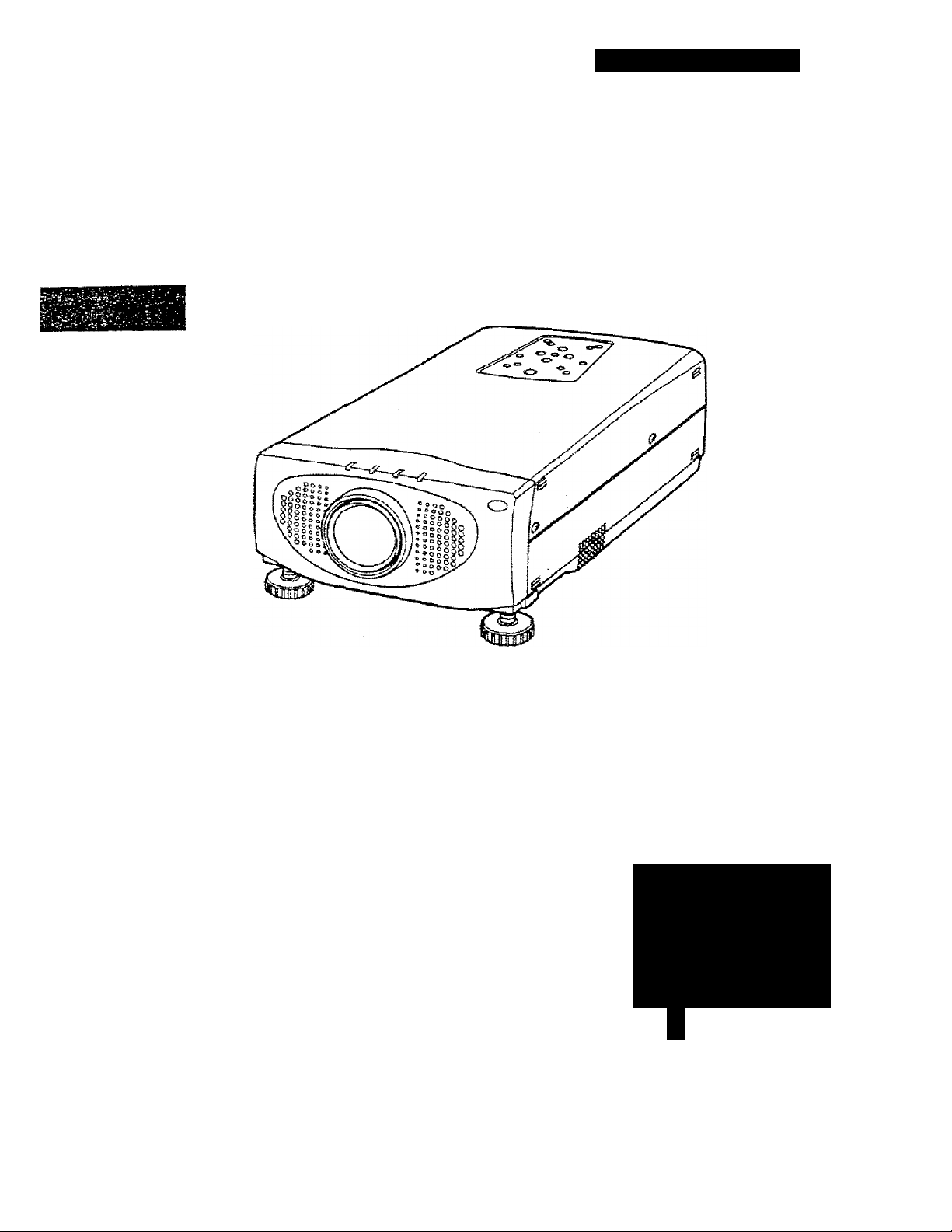
As the owner of a Desktop Projector 9250, you are probably eager to try out your new projector. Before you
we suggest that you spend a little time reading this guide to familiarize yourself with the operating procedur
so that you will receive maximum satisfaction from the many features included in your new projector.
This user’s guide wil! acquaint you with your projector’s features. Reading it will help us too. Through the yea
we have found that many service requests were not caused by problems with our projectors. They were cauE
by problems that could have been prevented, if the owner had foliowed the instructions in the guide.
You can often correct operating problems yourself. If your projector fails to work properly, s
’TROUBLESHOOTING” section on pages 49 ~ 50 and try the solutions marked for each problem.
SAFETY PRECAUTIONS
C
WARNING:
TO REDUCE THE RISK OF FIRE OR ELECTRIC SHOCK, DO NOT EXPOSE THIS APPLIANCE TO RAIN i
lOISTURE.
I his Projector has a grounding-type AC line plug. This is a safety feature to be sure that the plug wii
into the power outlet. Do not try to defeat this safety feature.
Intense light source. Do not stare directly into the projection lens as possible eye damage could resi Be especially careful that children do not stare directly Into the beam.
f
If the Projector will not be used for an extended time, unplug the new Projector from the power outlet.
READ AND KEEP THIS USER'S GUIDE FOR LATER USE.
CAUTION
ftlSK OF ELECTRIC SHOCK
DO NOT OPEN
CAUTION: to-REDUCE THE RISK OF ELECTRIC SHOCK,5DO NOT REMOVE COVER (OR’
BACK). NO USER-SERVICEABLE.PARTS INSIDE EXCÉPT LAMP REPLACEMENt, REFER
SERVICING TO QUALIFIED, SERVICE PERSONNEL.
THÏS SYMBOL INDICATES THATDANGERGUS VOLTAGE CONSTiTUTiNG A RISK OF
: ELECTRIC. SHOOK IS PRESENT WITHIN
-THIS'Unit.
. THIS SYMBOL INDICATES THAT-THERE A
IMPORTANT OPERATING AND MAINTENAN
INSTRUCTIONS IN THE USER'S GUIDE WITI
LTHiSUNIT. I :
' f r -i
я
Page 3
IMPORTANT SAFETY INSTRUCTIONS
с
All the safely and operating instructions should be read
I
^ore the product is operated.
. ,iead all of the instructions given here and retain fhem for
later use. Unplug this projector from AC power supply
before cleaning. Do not use liquid or aerosol cleaners. Use
a damp cloth for cleaning.
Do not use attachments not recommended by the
manufacturer as they may cause hazards.
Do not place this projector on an unstable cart, stand, or
table. The projector may fail, causing serious injury to a
child or adult, and serious damage to the projector. Use
only with a cart or stand recommended by the
manufacturer, or sold with the projector. Wall or shelf
mounting should follow the manufacturer's instructions,
and should use a mounting kit approved by the
manufacturer.
Do not expose this unit to rain or use near water... for
example, in a wet basement, near a swimming pool, etc...
Slots and openings in the back and bottom of the cabinet
are provided for ventilation, to insure reliable operation of
the equipment and to protect it from overheating.
,„The openings should never be covered with cloth or other
' I ’aterial, and the bottom opening should not be blocked by
:ing the projector on a bed, sofa, rug, or other similar
ace. This projector should never be placed near or
•
over a radiator or heat register.
This projector should not be placed in a built-in installation
such as a bookcase unless proper ventilation is provided.
This projector should be operated only from the type of
power source indicated on the marking label. If you are not
sure of the type of power supplied, consult your authorized
dealer or local power company.
Do not overload wall outlets and extension cords as this
can result in fire or electric shock. Do not allow anything to
rest on the power cord. Do not locate this projector where
the cord may be damaged by persons walking on it.
a. When the power cord or plug is damaged or frayed.
b. if liquid has been spilled into the projector.
c. !f the projector has been exposed to rain or water.
d. If the projector does not operate normally by following
the operating instructions. Adjust only those controls
that are covered by the operating instructions as
improper adjustment of other controls may result in
damage and will often require extensive work by a
qualified technician to restore the projector to normal
operation.
e. If the projector has been dropped or the cabirret has
been damaged.
f. When the projector exhibits a distinct change in
performance-this indicates a need for service.
When replacement parts are required, be sure the service
technician has used replacement parts specified by the
manufacturer that have the same characteristics as the
original pari. Unauthorized substitutions may result in fire,
electric shock, or injury to persons.
Upon completion of any service or repairs to this projector,
ask the service technician to perform routine safety checks
to determine that the projector is in safe operating
condition.
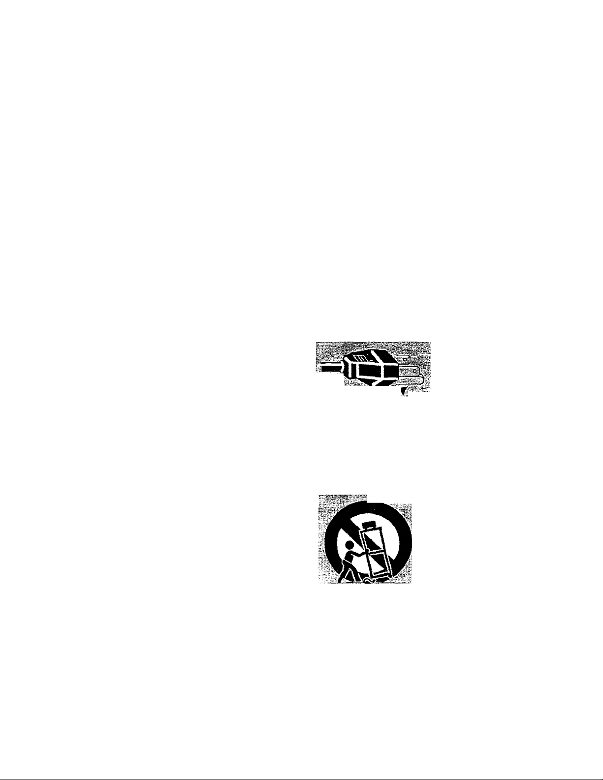
This projector is equipped with a
grounding type AC line plug.
■Г.-
Follow all
projectors.
For added protection to the projector during a lightning
storm, or when it is left unattended and unused for long
periods of time, unplug it from the wall outlet. This will
prevent damage due to lightning and poweriine surges.
.................
warnings
..
Should you be unable to insert
the plug into the outlet, contact
your electrician. Do not defeat
the safety purpose of this
grounding type plug,
and instructions marked on the
An appliance and cart combination
should be moved with care. Quick
stops, excessive force, and uneven
surfaces may cause the appliance
and cart combination to overturn.
Never push objects of any kind into this projector through
cabinet slots as they may touch dangerous voltage points
or short out parts that could result in a fire or electric
shock. Never spill liquid of any kind on the projector.
Do not attempt to service this projector yoursett as opening
or removing covers may expose you to dangerous voltage
or other hazards. Refer all servicing to qualified service
personnel.
¡lug this projector from wall outlet and refer servicing to
lifled service personnel under the following conditions;
If the projector is to be built into a compartment or similarly
enclosed, the minimum distances must be maintained.
Do not cover the ventilation slot on the projector.
Heat build-up can reduce the service life of your projector,
and can aiso be dangerous.
20 cm.
PROJECTOR
(FRONT)
■<—50 cm —>
■3 —
PROJECTOR
(SIDE)
■<4— 50 cm
w
Page 4

c
TABLE OF CONTENTS
V
INTRODUCTION
COMPATIBIUTY 5
IMAGE RESOLUTION
PORTABILITY 5 DIGITAL ZOOM ADJUSTMENT
UNPACKING THE PROJECTOR
TRADEMARKS
POWER REQUIREMENT 6 P-TIMER FUNCTION
DESCRIPTION
SETTING-UP THE PROJECTOR 8-9
POSITIONING
ROOM LIGHT 8
VENTILATION 8
ADJUSTABLE FEET 9
MOVING THE PROJECTOR 9 COLOR SYSTEM SELECT
CONNECTING THE PROJECTOR
CONNECTING THE COMPUTER
Connecting an IBM-compafible desktop computer 11
Connecting a Macintosh desktop computer
Connecting an IBM-compatible laptop computer
^|r Connecting a Macintosh PowerBook computer 14
CONNECTING THE VIDEO EQUIPMENT
CONNECTING AN EXTERNAL SPEAKER 17
OPERATION OF CONTROLS
TOP OF THE PROJECTOR
REAR OF THE PROJECTOR 20
OPERATION OF REMOTE CONTROL
REMOTE CONTROL BATTERY INSTALLATION
USING THE REMOTE CONTROL UNIT
CONTROL THE PROJECTOR
DIRECT OPERATION
MENU OPERATION
USING THE PROJECTOR
TO TURN ON THE PROJECTOR
TO TURN OFF THE PROJECTOR
DIRECT OPERATION
MODE SELECT
SOUND VOLUME ADJUSTMENT
PAGE
5
5
5
5 NO SHOW FUNCTION
7 FREEZE PICTURE FUNCTION
8
10-17
10-14
12
13
15-16
18-20
18-19 OTHER FUNCTION SETTING
21-23
23
23
24-26 SPLIT WIPE
24 LAMP AGE
25-26
27-46 TEMPERATURE WARNING INDICATOR
27 LAMP REPLACEMENT
27
27
27
28
SOUND MUTE FUNCTION
ZOOM ADJUSTMENT
FOCUS ADJUSTMENT
NORMAL PICTURE FUNCTION
AUTO IMAGE FUNCTION
MENU OPERATION
MODE SELECT
SOUND ADJUSTMENT
LANGUAGE ADJUSTMENT
PICTURE IMAGE ADJUSTMENT
PICTURE SCREEN ADJUSTMENT
COMPUTER SYSTEM SELECT
COMPATIBLE COMPUTER SPECIFICATION
AUTO IMAGE FUNCTION
PICTURE IMAGE ADJUSTMENT
PICTURE POSITION ADJUSTMENT
PC ADJUSTMENT
PICTURE SCREEN ADJUSTMENT
BLUE BACK
DISPLAY
CEILING
REAR
AIR FILTER CARE AND CLEANING
CLEANING THE LENS
TROUBLESHOOTING
TECHNICAL SPECIFICATIONS
paH
28
28
28
28
28
28
28
28
28
29-4
29
30
30
31
32
33
34
35
36^
3B\
39-4:
43
44-4'
44-41
44-4'
44-4i
44-4;
46
47
47
48
49
49-5C
51
Page 5

c
INTRODUCTION
The Desktop Projector 9250 is a muitimedia projector designed for portability, durability, and ease of use. The projector
utilizes built-in multimedia features, a palette of 16,77 miiiion colors, and active matrix liquid crystal display (LCD)
fechnoiogy.
^COMPATIBILITY
The projector is compatible with many different types of personal computers and video devices, including;
• IBM-compatible computers, including laptops, up to 1280 x 1024 resolution.
• Apple Macintosh and PowerBook computers up to 1280 x 1024 resolution.
• Various VCRs, video disc players, video cameras, DVD players, satellite TV tuners or other AV equipment using any of
the vtforldwide video standards, inciuding NTSC, NTSC4.43, PAL, SECAM and PAL-M.
IMAGE:RE|0IuT!9N-
The resolution of the projector’s projected image is 1024 x 768. The projector displays computer images just as they
appear on your computer's monitor. Screen resolutions between 1024 x 768 and 1280 x 1024 are compressed to 1024
X 768. The projector cannot display screen resolutions above 1280 x 1024. If your computer’s screen resolution is
higher than 1280 x 1024, reset it to a lower resolution before you connect the projector.
fPÒF^ABÌl^
The projector is extremely compact in size and weight. Having a sophisticated shape like an attaché case with a
retractable carrying handle, the projector will help you make poweilul presentations wherever you go.
UNPACKING THE PROJECTOR
The projector comes with the parts fisted below. Check to make sure all are included. If any parts aré missing, contact an
authorized dealer or sen/ice station.
• User’s Guide.
f -
C Power Cords (UL and European types),
emote Control Transmitter Unit and batteries.
5 Lens Cover.
• Protective Dust Cover.
• VGA Cable.
• VGA/MAC Adapter.
• Mouse Cable for PS/2 port.
• Mouse Cable for serial port.
• Mouse Cable for ADB port.
• S-video cable (Mini DIN-4 type).
• AV cable (RCA type x 3],
• PC audio cable (Stereo mini jack).
--¡sii»-.
TRADEMARKS
• Apple, Macintosh, and PowerBook are trademarks or registered trademarks of Apple Computer, Inc.
• IBM and PS/2 are trademarks or registered trademarks of international Business Machines, Inc.
• Proxima is a registered trademark of Proxima Corporation.
• Desktop Projector is a trademark of Proxima Corporation.
• Other trademarks are the property of their respective owners.
Page 6
c
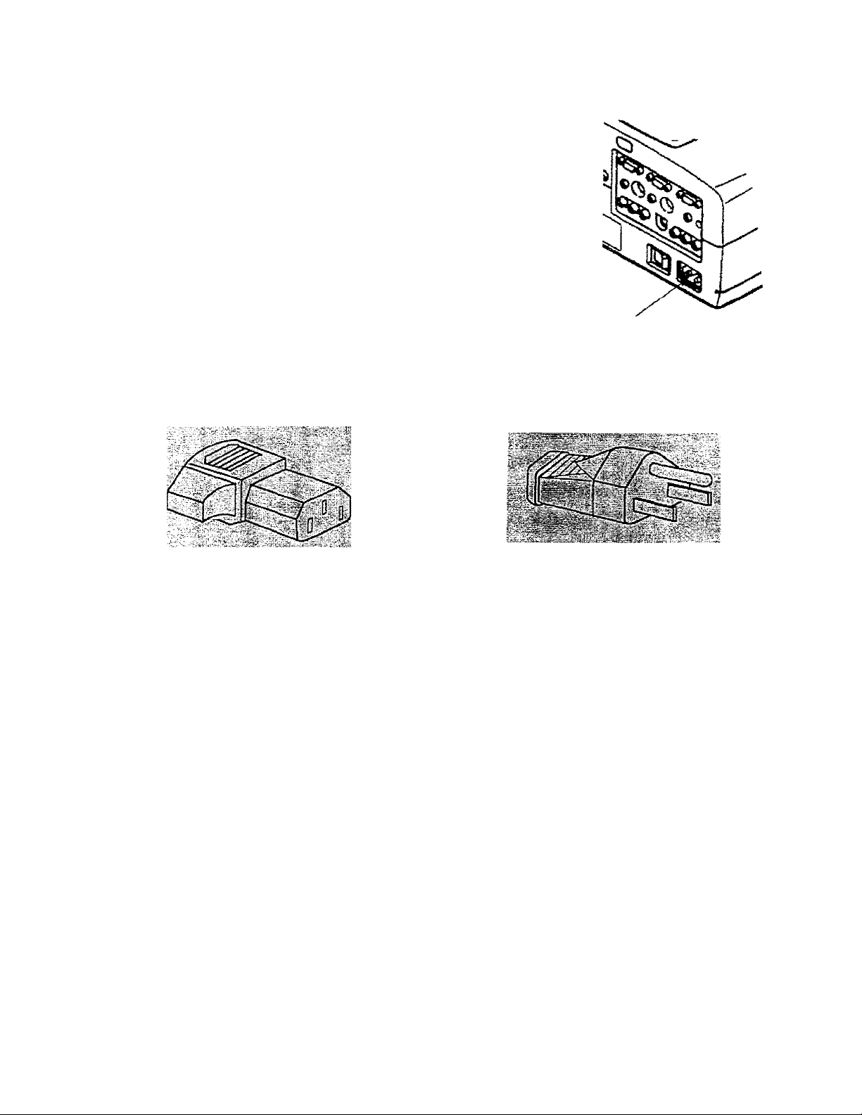
POWER REQUIREMENTS
Your projector uses nominal input voltages of 100-120 VAC or
200-240 VAC. The projector automaticaiiy selects the correct
mput voltage. !t is designed to work with single-phase power
systems having a grounded neutral conductor. To reduce the risk
of electrical shock, do not plug into any other type of power
system.
Consult your authorized dealer or service station if you are not
sure of the type of power supply being in use.
Connect the AC power supply cord (provided) to
the projector.
The socket-outlet must be near this equipment
and must be easily accessible.
Projector side (Female)
AC outlet side (Male)
Page 7
c
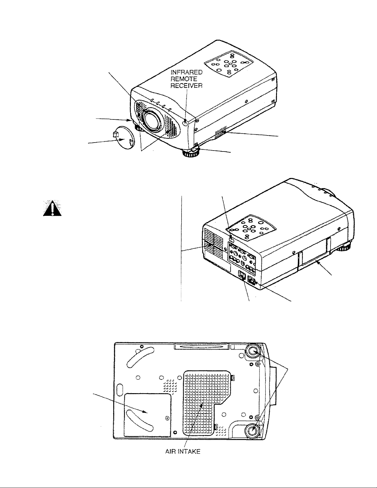
DESCRIPTION
FRONT
PROJECTiON LENS
FEET LOCK
BUTTON
REMOVABLE
LENS COVER
SPEAKER
RÈÀR
EXHAUST VENT
CAUTION HOTAIR!
Air. foiown from the exhaust vent is hot.
Observe the following when handling your
projector or choosing a location to install it.
• Keep heat-sensitive objects away from the
exhaust port.
• If you set the projector on top of a metallic
surface, the suilace will become hot because
of the hot air exhaust. Be careful when
handling.
• Do not touch the cabinet near to the exhaust
vent area, and especially screws and metallic
parts. These parts will become hot while the
projector is used.
INFRARED
REMOTE
RECEIVER
MAIN ON/OFF
SWITCH
AIR INTAKE
VENT
FEET LOCK
BUTTON
CARRY HANDLE
POWER CORD
CONNECTOR
BOTTOM
LAMP COVER
ADJUSTABLE
FEET
VENT
Page 8
c
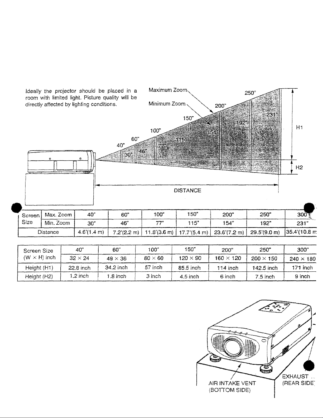
POSmONING:
SETTING-UP THE PROJECTOR
This projector is basically designed to project on a fiat projection surface.
This projector can be focused from 4.6’ (1.4m) ~ 35.4’ (10.8m).
Use the illustration befow as an example when positioning the projector to the screen.
ROOM LIGHT
300”
VENTILATION
This projector is equipped with a cooling fan to protect it from
overheating. Pay attention to the following to ensure the ventilation
and avoid a possible risk of fire and maifunction.
Do not cover the vents with papers or other materials.
Keep the rear grill at least 3.3' (1m) away from any
A
object.
Make sure that there are no objects under the projector.
An object under the projector may prevent the projector
from taking the cooling air through the bottom vent.
Page 9
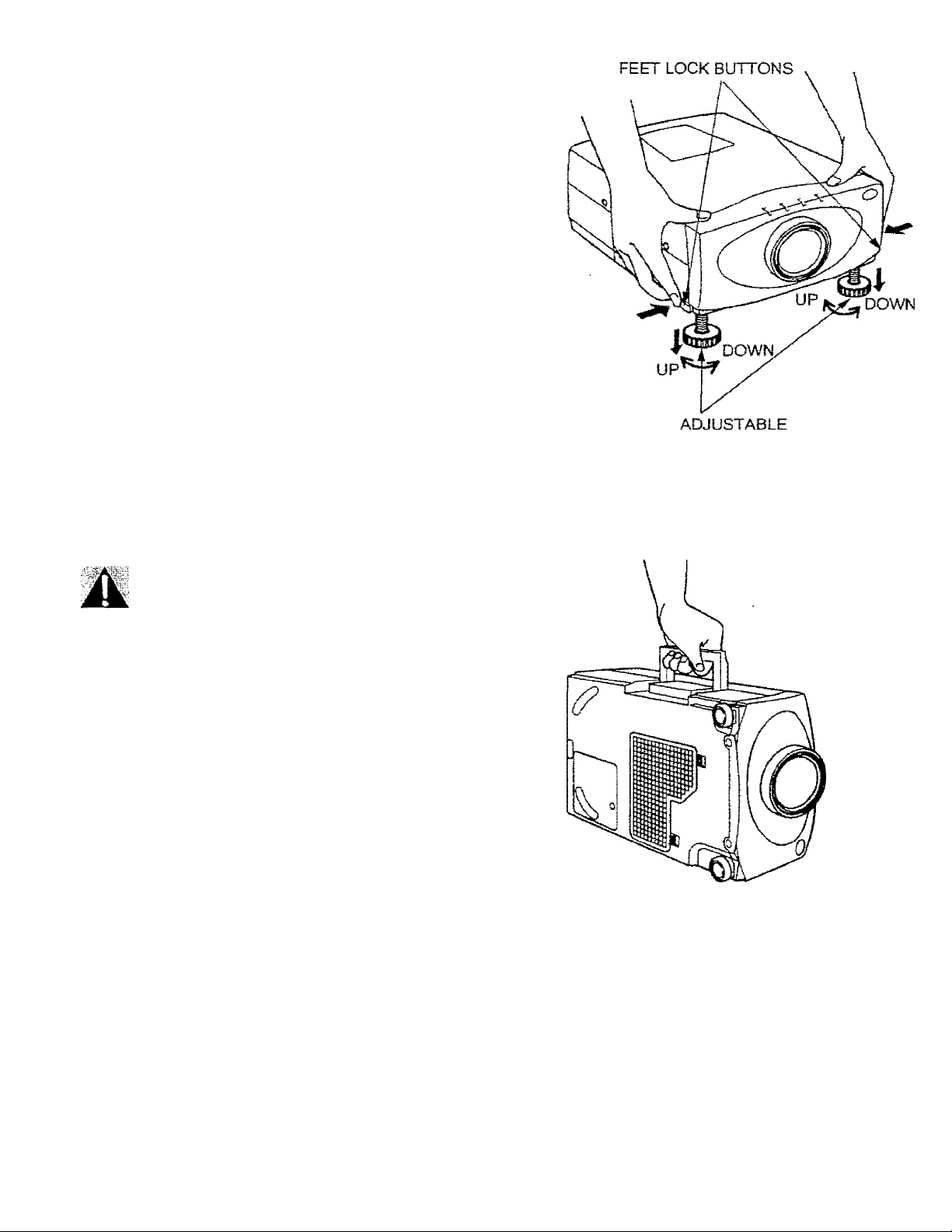
ADJUSTABLE FEET
Picture tiii and projection angle can be adjusted by ADJUSTABLE
FEET, Projection angle can be adjusted 0 to 6 ^ .
Lift the front of the projector and press the feet lock buttons (left
and right) under the sides of the projector.
When the buttons are pressed, feet lock is released.
2. Release the buttons at desired front high! position, (feet is
locked).
3. Turn the adjustable feet and adjust picture position and tiit.
FEET
C
MOVING THE PROJECTOR
Use the carry handle when moving the projector.
Replace the lens cover and retract the
adjustable feet when moving the projector to
prevent damage to the projector.
CAUTION IN CARRYING OR TRANSPORTING THE PROJECTOR
• Do not drop or give a shock to the projector, otherwise damage or mutfunction may result.
• When carrying the projector, use a Proxima recommended Carrying Case.
• Do not transport the projector by using a courier or transport service in an unsuitable transport case. This may
cause damage to the projector. To transport the projector through a courier or transport service, use a Proxima
recommended Case.
• For a carrying or transportation cases, contact a Proxima authorized dealer.
Page 10

c
CONNECTING THE PROJECTOR
Your projector is equipped with various audioArideo inputs and outputs including Computer HDB15-pin (VGA) term^H
-lonitor HDBI 5-pin (VGA) terminals and S-VHS video . IP
•
CONNECTING THE COMPUTER
CONNECTING TO THE COMPUTER INPUT HDB15-PIN (VGA) TERMINALS (1 and 2Ì
Personal computers can be connected to the HDB15-pin (VGA) terminai on the projector,
• Connect the computer to these terminais using the VGA cable and VGA/MAC adapter (provided).
WARNING: For projectors, the VGA cable provided is designed to reduce RFI (Radio Frequency Interference
emissions. For reguSatory compliance reasons, this cable must be used and must not be replaced by an
other cable.
CONNECTING TO THE MONITOR OUTPUT HDB15-P1N (VGA) TERMINAL
This terminal contains the information that is viewed on the screen.
An extemaimonitor can be connected to the HDB15-pin (VGA) terminal on the projector.
• Connect the monitor to this termina! using a monitor cable (not provided).
HD815-PIN
TERMINAL
5'4 3-2 ^
0 0 0-00
10 9-8 7 6."_7
0-0-0 0 o 7
I o’o b o*.b' 7.
VJ5'1-413t2i1 yt
Pin No./Signal
1 Red input 9 Non Connect
2 Green input
3 Blue input 11 Sense 0
4 Sense 2 12 Sense 1
5 Ground (Horiz. sync.) 13 Horiz. sync.
6 Ground (Red)
7 Ground (Green)
8- Ground (Blue)
Pin No./Signal
1Q Ground (Vert, syns
14 Vert. sync.
15 Reserved
CONNECTING TO THE COMPUTER AUDIO INPUT JACKS (1 and 2)
• Connect audio outputs from your computer to these jacks using the audio cable (not provided).
CONNECTING TO THE MULTI-POLE 12-PiN (CONTROL PORT) CONNECTORS (1 and 2)
• If you wish to control the computer with projector’s remote control unit, you must connect control port (PS/2, Serial c
ADB port) on your computer to projector’s control port with cable, (three type of cables provided)
Serial
Poii
TxD
RxD
READY
GND
ADBirj:
iPo'rt
ADB
GND
CONTROL PORT CABLE REMOVAL HINT
Disconnect control port cable
with foilowing steps.
1. Hold the portion (A) of the
connector with one hand,
2. Pull the portion (B) arrow
direction and remove
connector.
iXL
A
CONTROL PORT
10
11
d2
PS/2=
,i=*ort
.1
2-
CLK
DATA
6
8
GND
~B.
NOTE: The RxD port (5 pin on the' Serial Port) is provided on control port 2 connector only. If you control the proje^
by computer, you must connect control port 2 connector.
m
Page 11
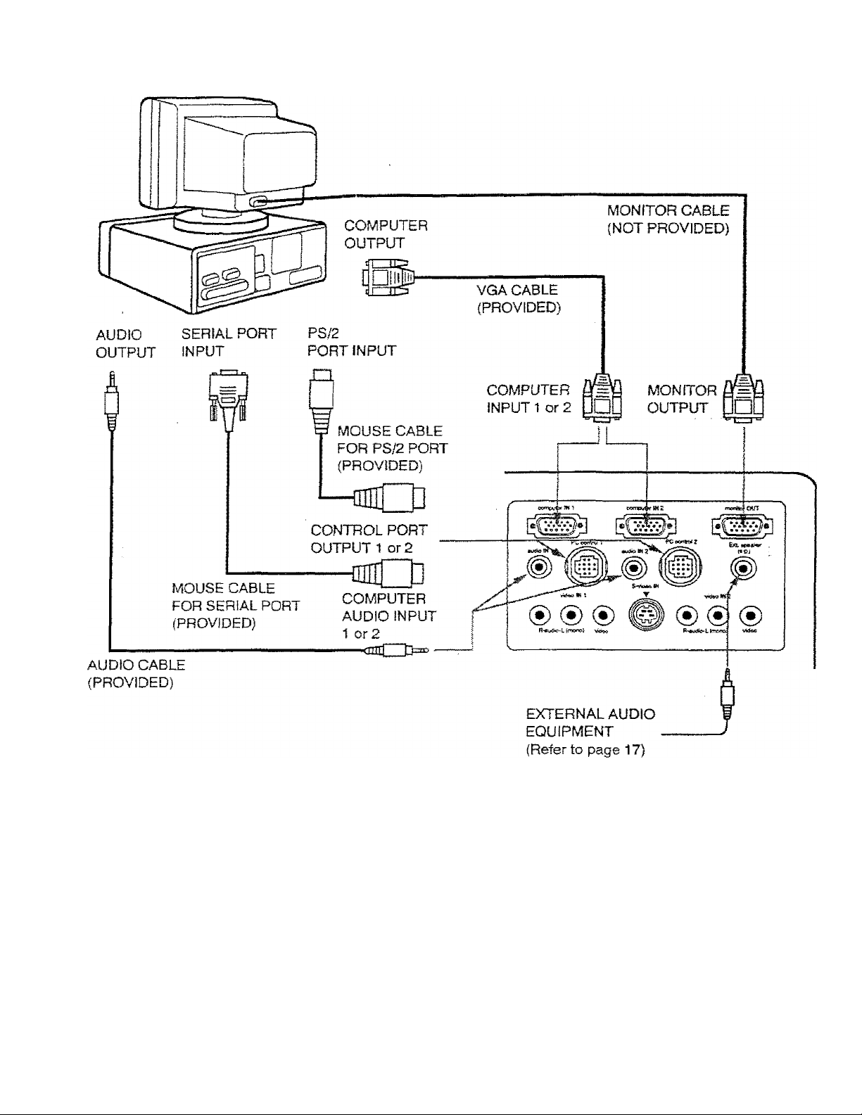
Connecting an IBM-compatible desktop computer
COMPUTER
NOTE: The hook up should be done as per the above illustration. After hook up, turn on the projector, monitor,
computer, in that order.
*
• 11
Page 12
Connecting a Macintosh desktop computer
COMPUTER
VGA/MAC ADAPTER
Set the dip switches as shown in the tabie below depending on the
RESOLUTION MODE that you want to use before you turn on the
projector and computer.
ON
RESOLUTIQN^MODE
13' MQDE5iB40;^=;A80) '
,:1E-MODE:i832X:624)
1.S' MODE (1024 X 768)'
'21” MODE (1152 X .870)
NOTE: The hook up should be done as per the above illustration. After hook up, turn on the projector, monitor,
computer, in that order.
SW1,;SW2
ON,
ON ■
OFF
OFF
■ ON' hON":
ON
ON
'iSVW:
SW3:
OFF
OFF
OFF -ON'
OFF
ON
■ON':
ON
OFF
OFF
OFF
OFF
OFF OFF
OFF
OFF
12
E
OFF
Page 13
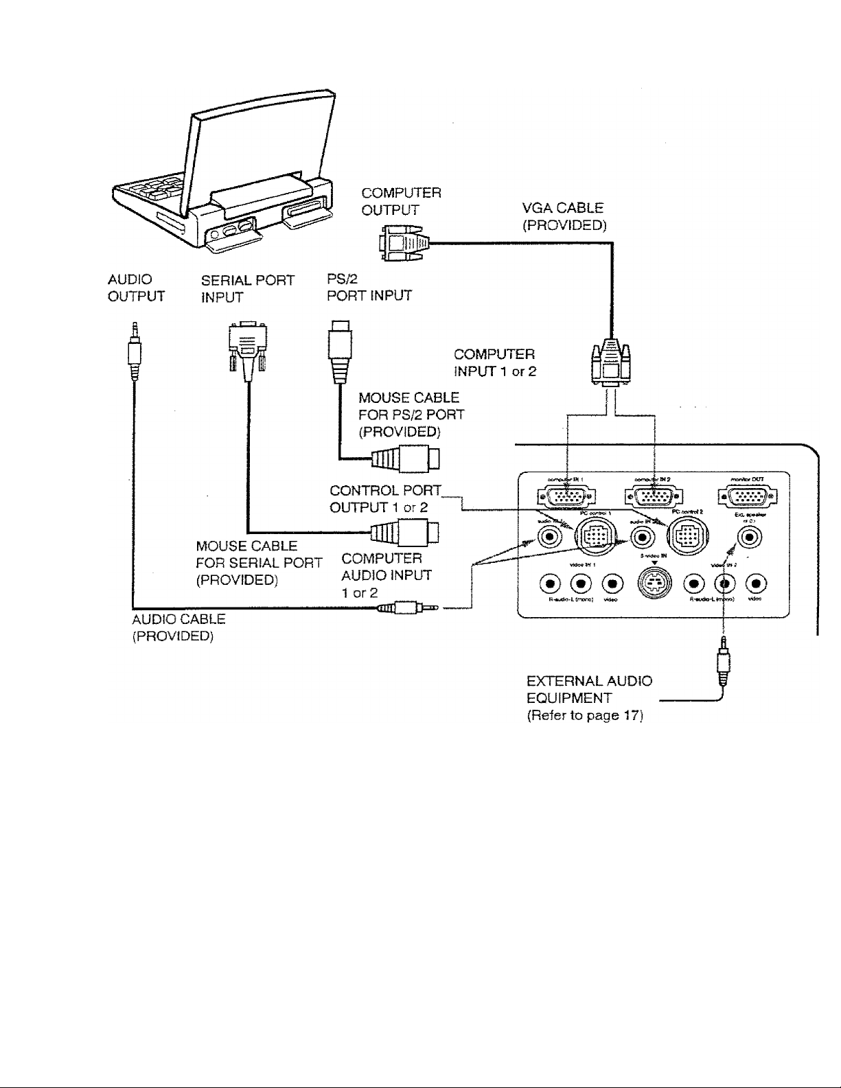
Connecting an IBM-compatible laptop computer
COMPUTER
NOTE: The hook up should be done as per the above illustration. After hook up, turn on the pro|ector, computer, in
that order.
13-
Page 14
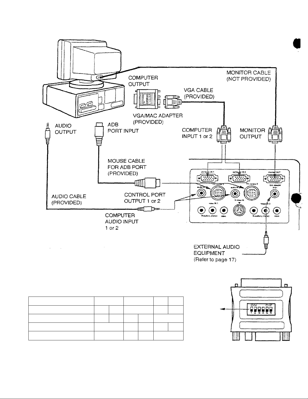
Connecting a Macintosh PowerBook computer
COMPUTER
The Macintosh PowerBook requires the use of the
PowerBook Video Adapter shipped with the PowerBook.
TO POWERBOOK
VIDEO ADAPTER
VGA/MAC ADAPTER
AUDIO
OUTPUT
ADB
PORT INPUT
MOUSE CABLE
FOR ADB PORT
(PROVIDED)
(PROVIDED)
COMPUTER
INPUT 1 or 2
VGA CABLE
(PROVIDED)
DUE ]
CONTROL PORT
OUTPUT 1 or 2
-<tnTt 0=113-
AUDIO CABLE
(PROVIDED)
Set the dip switches as shown in the table below depending on the
RESOLUTION MODE that you want to use before you turn on the
projector and computer.
■RESOLUTION MODE L SW4'
■ 13” MODE (640-X 480) ■=
16” MODE {832 X 624): ;■
19” MODE (1024 x -7#)- OFF
:21-MODE (1152 X 870)
COMPUTER
AUDIO INPUT 1 or 2
SW2
,SW3 SW4 SW5
ON OFF
QN^
OFF
ON
ON, OFF on;
ON'
-ON
ON
ON
OFF
OFF
ON|
OFF OFF
OFF
OFF
OFF OFF
OFF
OFF
EXTERNAL AUDIO
EQUIPMENT
(Referto page 17)
VGA/MAC ADAPTER
ON
OFF
NOTE: The hook up should be done as per the above illustration. After hook up, turn on the projector, computer,
that order.
. -id ■
Page 15

CONNECTING THE VIDEO E0ÜÍPMÉNT
CONNECTING TO THE AV INPUT 1 JACKS
'onnect to the video and audio outputs of a VCR, video disc player, video camera, satellite TV tuner or other AV
quipment.
• Connect audio/video outputs from external sources to these input jacks using the audio/video cable.
• If the audio signal from the AV equipment is stereo, be sure to connect the right and left channels to the respective right
and left audio input jacks.
• If the external audio signal is monaural, connect it to the left jack.
S-VHS FORMAT VCR CONNECTION
The AV 1 input includes an extra video input jack marked S-ViDEO to allow connection to an S-VHS format VCR that has
separate Y/C video signals. The S-VIDEO jack has priority over the VIDEO jack.
CONNECTING TO THE AV INPUT 2 JACKS
Connect to the video and audio outputs of a VCR, video disc player, video camera, satellite TV tuner or other AV
equipment,
• Connect audio.Video outputs from external sources to these input jacks using the audio/video cable.
• If the audio signal from the AV equipment is stereo, be sure to connect the right and left channels to the respective right
and left audio input jacks.
• If the external audio signal is monaural, connect it to the left jack.
h
15 •
Page 16
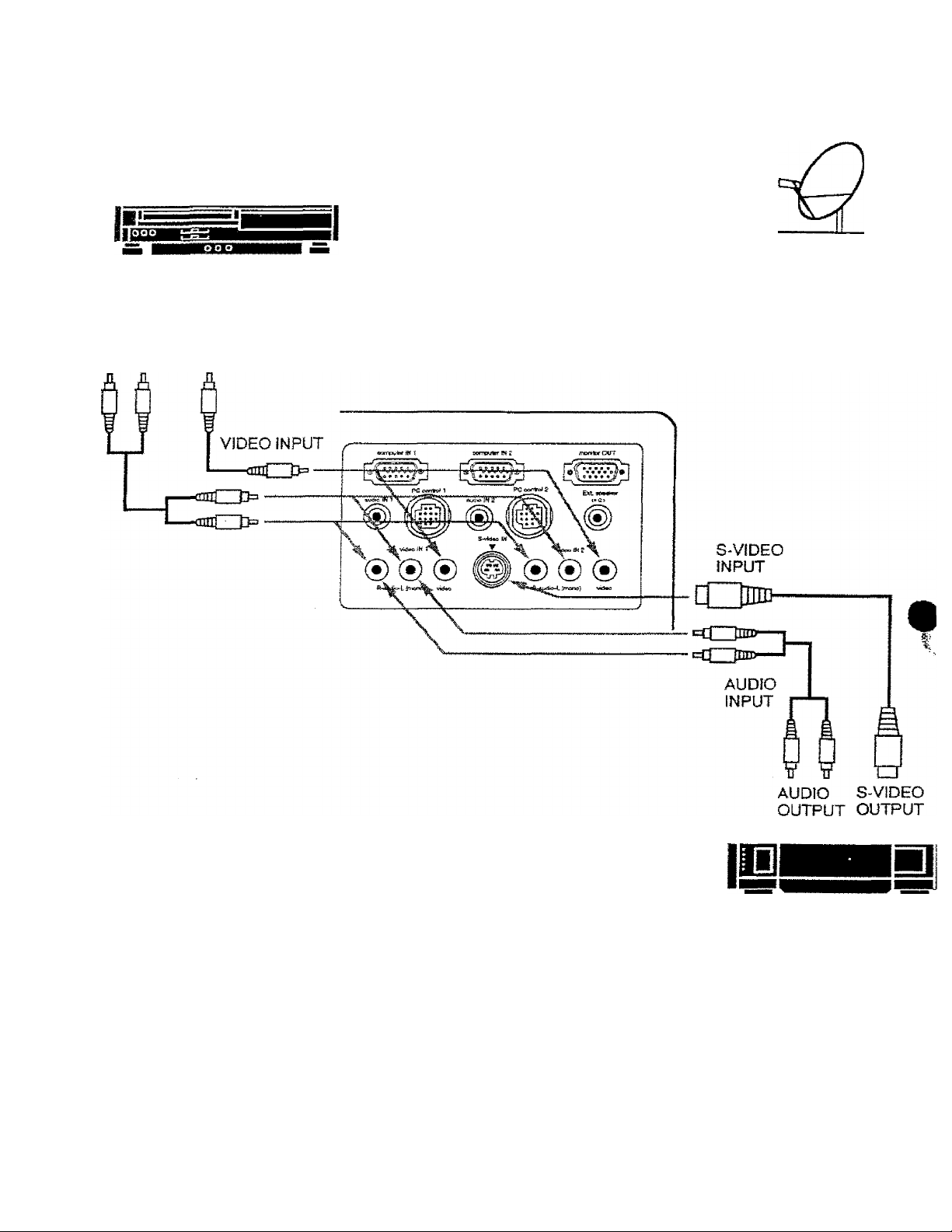
Connecting the Video Equipment
I
-----------------------------------------
Video Cassette Recorder
-
VIDEO EQUIPMENT
DVD Player
Video Disc Player
Satellite
TV Tuner
L R
AUDIO
OUTPUT
VIDEO
OUTPUT
S-VHS VCR
Etc...
NOTE; The hook up should be done as per the above illustration. After hook up, turn on the projector, video equipment
in that order.
Page 17

CONNECTING AN E^CTERNADIPEAKER
CONNECTING TO THE EXT. SP. JACK (3.5mm mini stereo type)
^^his jack outputs stereo speaker sound which viewing on screen, if you use external speaker system, connect stereo
^Bpe external speaker jack. Internal speaker sound is disconnected when speaker jack is connected.
EXTERNAL
SPEAKERS SYSTEM
17
Page 18

c
OPERATION OF CONTROLS
FRONT
INDICATORS
Page 19

LAMP REPLACEMENT INDICATOR
Light is orange when projection lamp is nearing end of service life.
O
TEMPERATURE WARNING INDICATOR
PlirtQh&c: rprfi whf^.n mtprnsl nrnlftntnr tp.mnAf
Flashes red when internal projector temperature is too high,
READY INDICATOR
Light is green when projector lamp is ready to be turned on.
A LAMP POWER INDICATOR
Light is dim when the projector is on.
Light is brightened when the projector is in stand-by mode.
A LAMP POWER ON/OFF BUTTON
Used to turn projector on or off,
A COMPUTER SELECT BUTTON
Used to select computer mode (Computer 1 or Computer 2).
VIDEO SELECT BUTTON
Used to select video mode Video 1 or Video 2).
A VOLUME BUTTONS
Used to adjust volume.
A MENU BUTTON
This button will activate the MENU operation.
Use this button, the POINT UP/DOWN/LEFT/RiGHT buttons and the SELECT button to make adjustments to the
projector's setting in MENU operation.
II AUTO IMAGE BUTTON
<D
€
Used to operate the AUTO IMAGE function.
ZOOM BUTTONS
Used to operate power zoom lens.
FOCUS BUTTONS
Used to operate power focus system.
POINT UP/DOWN/LEFT/RlGHT BUTTONS
To select an item on the MENU that you want to adjust. To select an item, move the arrow by pressing these
buttons (UP, DOWN. LEFT or RIGHT),
'ii SELECT BUTTON
This button has different functions depending on when used. This button is used to execute the item selected, to
increase or decrease the values in certain items such as CONTRAST or BRIGHTNESS.
• 19 ■
Page 20

REAR OF THE PROJECTOR
0
J
1
t «orrcl
#
COMPUTER INPUT-1 TERMINAL
Used to connect a computer to the projector.
COMPUTER INPUT-2 TERMINAL
Used to connect a computer to the projector.
MONITOR OUTPUT TERMINAL
Used to connect a monitor to the projector.
COMPUTER AUDIO INPUT-1 JACK
mini stereo type
Used to connect a computer audio input to the
projector,
CONTROL PORT-1 CONNECTOR
Used to connect a mouse cable to the projector.
COMPUTER AUDIO INPUT JACK 2
mini stereo type
Used to connect a computer audio input to the
projector.
CONTROL PORT-2 CONNECTOR {SERIAL PORT)
Used to connect a mouse cable to the projector.
NOTE: Control port-2 connector can be also used
as serial port.
AUDIO lNPUT-1 JACKS
Used to connect an audio input to the projector.
VIDEO lNPUT-1 JACK * -
Used to connect a video source to the projector.
S-VIDEO INPUT JACK
Used to connect a S-VHS video source to the projectc
AUDIO INPUT-2 JACKS
Used to connect an audio input to Ihe projector.
VIDEO INPUT-2 JACK
Used to connect a video source to the projector.
EXT, SP. JACK (3.5 mm mini stereo type)
Used to connect an external speaker system.
Page 21

c
OPERATION OF REMOTE CONTROL
This remote control unit not only operates the projector but may
Iso be used as a wireless mouse for a PC. One joystick and four
uttons are used for wireless mouse operation.
The wireless mouse is active when the PC cursor is displayed on
the screen. When the projector menu is displayed on the screen
instead of the cursor, the wireless mouse cannot be used.
NOTE: To use the unit as a PC wireless mouse, connect the
projector to the PC with the attached cable. Signals from
the projector are transmitted to the PC, enabling the remote
control unit to be used as a PC wireless mouse. (Refer to
"CONNECTING THÈ PROJECTOR” in pages 10 to 14 tor
the connection.)
See caution when operating the Laser remote
LASER RADIATION
DANGER
Diode Laser
<5,0 miHiwatl max. output
DO NOT STARE INTO BEAM
Wavelength 630-680 nm
CiasE fila Laser Product
control. Laser light can cause harm if projected at
the human eye. Observe the cautions on the Laser
Warning label located on the rear of the remote
control. Do not point the laser directly into any
person’s eyes.
— 21 —
Page 22

D. ZOOM BÜTTON
Used to select digital zoom function.
•©
e
o
e
©
©
« MODE BUTTON
©
I) FOCUS BUTTONS
©
©
normal button m
Use to reset to normal picture adjustment preset by factory. fjj|
AUTO IMAGE BUTTON
Used to operate AUTO IMAGE function.
BLANK BUTTON
Used to change the screen into black image.
MENU BUTTON
This button will activate the MENU operation. Use this button, the POINT UP/DOWN/LEFT/RIGHT button and the
SELECT button to make adjustments to the projector's setting in MENU operation. -
LAMP POWER ON/OFF BUTTON
Used to turn the projection lamp on or off.
FREEZE BUTTON
Use this button to freeze on-screen image.
P-TIMER BUTTON
Used to operate the P-TIMER function.
Used to select video source. {Computer 1, Computer 2 Video 1 or Video 2 Input)
Used to operate power focus system.
VOLUME BUTTONS
Used to adjust volume.
•©
ZOOM BUTTONS
Used to operate power zoom iens.
SOUND MUTE BUTTON
©
Used to mute sound.
’»* JOYSTICK
©
(POINT UP/DOWN/LEFT/RfGHT BUTTON)
When used as a remote for the projector control.
To select an item on the MENU that you want to adjust. To select an item, move the arrow by move the joystick
forward, backward, left or right.
When used as a wireless mouse
Acts like a mouse. Move the joystick in the direction that you want to move the screen cursor. The further you
move the joystick in any direction, the faster the cursor will move.
SELECT {LEFT CLICK) BUTTON
©
When used as a remote for the projector control.
This button has different functions depending on when used. This button is used to select menu items.
When used as a wireless mouse
This button has the same function as the left button in a PC mouse.
RIGHT CLICK BUTTON
This button has the same function as the right button in a PC mouse. Pressing this button does not affect any
operation when in MENU mode,
DRAG LEFT/RIGHT BUTTONS A
Use this button and the joystick to drag a selected screen object. Press and release the Drag Left or Right buttdUP
the button glows and the remote control is in Drag mode. Move the joystick in the direction that you want to drag
the screen object. Press and release a second time to drop the object at the new screen location.
*j LASER BUTTON
©
Press and hold to activate the laser pointer.
Page 23

REMOTE CONTROL BATTERY JNSTALLATiON
- O'".'Slide the "batteries intoihe
-£m'-'cqmpartmeni. -‘.j’f
- 'M.y i ’i;/
Note; For correct polarity {■+ and -
terminal), be sure the battery
terminals are in contact with
the pins in the compartment.
USING REMOTE CONTROL
Point the remote control toward the projector’s front or rear receiver windows whenever using the remote control.
Maximum operating range for the remote control is about 16.4’ (5m) and 60"" front and rear of the projector.
To insure safe operation, please observe the following precautions:
#
• Use (2) AAA type alkaline batteries,
• Change two batteries at the same time.
• Do not use a new battery with a used battery.
• Avoid contact with water.
• Do not drop the remote control unit.
• If batteries have leaked on the remote control, carefully wipe the case
dean and load new batteries.
— 23 —
Page 24

с
CONTROL THE PROJECTOR
The praiector has two types of operation: DIRECT OPERATION and MENU OPERATION. DIRECT OPERATIONS
allows you to operate the projector by using one button without showing the MENU. In MENU OPERATION тос1ея1
you display menus where you can adjust the projector's settings. Follow the instruction for each control.
DIRECf OPÉRATION
" T ADJUST ITEM ;
POWER CDN/OFFvii?
MODE, SELECT, T- ^
SOUND VOLUME
iSOUNDMUTE^:; i
'¿OpM,; - : . . ^ .
FOCUS . k : ^
blGltALZOOM.v -
NORMAL PICTURE . .
NOSHOW . -ikk:?
, .. - ' I" . - " -i,.
TOP CONTROL '= '
OF THE PROJECtote v;
POWER ON-OFF BUTTON POWER ON-OFF BUTTON
COMPUTER BUTTON
VIDEO BUTTON
VOLUME (+) and ( - ) BUTTONS VOLUME (+) and ( - ) BUTTONS
NOT AVAILABLE MUTE BUTTON
ZOOM (/\) and (v) BUTTONS ZOOM (/\) and (\y) BUTTONS
FOCUS (/\) and (\/) BUTTONS
NOT AVAILABLE
-'t
NOT AVAILABLE
NOT AVAILABLE
■ Vr REH^OTE CONTROL UNlT. ^rl
MODE BUTTON
FOCUS {/A,) and (\/ ) BUTTONS
D. ZOOM BUTTON
SELECT BUTTON
RIGHT CLICK BUTTON
POINT (UP/DOWN/LEFT/RIGHT)
BUTTON fl
NORMAL BUTTON
BLANK BUTTON
f
P. TIMER '
-FREEZE PICTURE k AUTO IMAGE
NOT AVAILABLE
NOT AVAILABLE
AUTO IMAGE BUTTON
P. TIMER BUTTON
FREEZE BUTTON
AUTO IMAGE BUTTON
Page 25

MENU OPERATION
ADJUST ITEM ,
MODE SELECT
-TOPCONTROL^
- ‘.fdF T-rtE PRO JECTOJ^, - ^,,: V
MENU BUTTON
POINT LEFT/RiGHT BUTTONS
SELECT BUTTON
POINT UP/DOWN BUTTONS
SELECT BUTTON
1. COMPUTERA/IDEO MODE
ADJUST ITEM '
,5 ; le , ,|9 ■ -u - y. : . 55P».*
SOUND^^ '■ i
SOUND VOLUME
SOUND MUTE
LANGUAGE ‘
^ > s -’c-S.«- -
- ■- .-'i'--'-. -Is"-" - ;
SETT1NG;> -. • :j.
BLUE.BACK. •,
DISPLAY
CEILING:-, -i-:
rearV'^
SPLIT WIPE.“ u:
LAMPAGE
- . ‘ -- :.: .REMOTG GONTROUi UNrri; ; ' . ,
MENU BUTTON
POINT LEFT/RIGHT BUTTONS
SELECT BUTTON
POINT UP/DOWN BUTTONS
SELECT BUTTON
MENU BUTTON
POINT LEFT/RIGHT BUTTONS
SELECT BUTTON
POINT UP/DOWN BUTTONS
SELECT BUTTON
REMOTE CONTROL UNIT
MENU BUTTON
POINT (LEFT/RIGHT) BUTTON
SELECT BUTTON
POINT (UP/DOWN) BUTTON
SELECT BUTTON
MENU BUTTON
POINT (LEFT/RIGHT) BUTTON
SELECT BUTTON
POINT (UP/DOWN) BUTTON
SELECT BUTTON
MENU BUTTON
POINT (LEFT/RIGHT) BUTTON
SELECT BUTTON
POINT (UP/DOWN) BUTTON
SELECT BUTTON
..........
2. VIDEO MODE
COLOR SYSTEM “'
PICTURE IMAGE
COLOR
TINT
CONTRAST r"
BRIGHTNESS - " ...
SHARPNESS
PICTURE SCREEN
WIDE
t
REGULAR
ADJUST ITEM. T
■ • 'r- C -
FLTOPVcbNtROt., -¿iH-fer.'--,.-
OF THE PROJECTOR
MENU BUTTON
POINT LEFT/RIGHT BUTTONS
SELECT BUTTON
POINT UP/DOWN BUTTONS
SELECT BUTTON
MENU BUTTON
POINT LEFT/RIGHT BUTTONS
SELECT BUTTON
POINT UP/DOWN BUTTONS
SELECT BUTTON
■ REMD^T^CONTROLC UNIT.: ‘
MENU BUTTON
POINT (LEFT/RIGHT) BUTTON
SELECT BUTTON
POINT (UP/DOWN) BUTTON
SELECT BUTTON
MENU BUTTON
POINT (LEFT/RiGHT) BUTTON
SELECT BUTTON
POINT (UP/DOWN) BUTTON
SELECT BUTTON
— 25 —
Page 26

3. COMPUTER MODE
ADJUST ítem
COMPUTER SYSTEM :
--1-' "a-
AÚTO IMAGE
fVSiE SYNC
TOTAL'JDOTS
. POSjflON *! ..T
P Í CTÜRE i M AG Ey ^CY;
.. FINE SYNC:, v. LIY
- TOTAL DOTS tf
WHITE BALANCE ,
CONTRAST T' F C,
BRIGHTNESS i
PICTURE POSITION ^ -
' ~ K ' ^
■ ■ ' ' V „.T'" • ».CsVi
•• . ' ■ ■ ...j; •J.i
TOP CONTROL ,
--- ..
OFTHE,PROJECTOR/,'V. ri;
1 MENU BUTTON
i POINT LEFT/RiGHT BUTTONS
SELECT BUTTON
POINT UP/DOWN BUTTONS
SELECT BUTTON
MENU BUTTON
POINT LEFT/RiGHT BUTTONS
SELECT BUTTON
POINT UP/DOWN BUTTONS
SELECT BUTTON
MENU BUTTON
POINT LEFT/RiGHT BUTTONS
SELECT BUTTON
POINT UP/DOWN BUTTONS
SELECT BUTTON
MENU BUTTON
POINT LEFT/RiGHT BUTTONS
SELECT BUTTON
POINT LEFT/RIGHT/UP/DOWN
BUTTONS
SELECT BUTTON
T" ■LvyT-/
Y:REMQTE CONTROL UNIT ^
MENU BUTTON
POINT (LEFT/RIGHT) BUTTON
SELECT BUTTON
POINT (UP/DOWN) BUTTON
SELECT BUTTON
MENU BUTTON
POINT (LEFT/RIGHT) BUTTON
SELECT BUTTON
POINT (UP/DOWN) BUTTON
SELECT BUTTON
MENU BUTTON
POINT (LEFT/RIGHT) BUTTON
SELECT BUTTON
POINT (UP/DOWN) BUTTON
SELECT BUTTON
MENU BUTTON
POINT (LEFT/RiGHT) BUTTON
SELECT BUTTON
POINT (LEFT/RIGHT/UP/DOWN) W
BUTTON T
SELECT BUTTON
: PC ADJUSTMENT-^:- V
- * * . - -^.o- ^
PICTURE SCREEN:, j
TRUE - rj ' 1. .
DIGITAL.ZOOM '
MENU BUTTON
POINT LEFT/RIGHT BUTTONS
SELECT BUTTON
POINT UP/DOWN BUTTONS
SELECT BUTTON
MENU BUTTON
POINT LEFT/RIGHT BUTTONS
SELECT BUTTON
POINT UP/DOWN BUTTONS
SELECT BUTTON
POINT LEFT/RlGHT/UP/DOWN
BUTTONS
MENU BUTTON
POINT (LEFT/RIGHT) BUTTON
SELECT BUTTON
POINT (UP/DOWN) BUTTON
SELECT BUTTON
MENU BUTTON
POINT (LEFT/RiGHT) BUTTON
SELECT BUTTON
POINT (UP/DOWN) BUTTON
SELECT BUTTON
SELECT BUTTON
FRONT CLICK BUTTON
POINT (UP/DOWN/LEFT/RiGHT)
BUTTON
NOTES:
1.If you switch to DIRECT operation by pressing a DfRECT operation button while in MENU mode, the menus
will disappear and the MENU operation wiil end.
2. You can use the REMOTE CONTROL UNIT or the TOP CONTROL OF THE PROJECTOR to operate the
MENU operation.
26-
Page 27

USING THE PROJECTOR
c
raTURN QN THE PROJEGTOR
bonnect the projector to a source (Computer, VCR, Video Camera, Video Disc Player, etc.) using the appropriat«
terminals on the rear of the projector (See "CONNECTiNG THE PROJECTOR" section on pages 10-17).
Connect the projector’s AC power cord into a wall outlet and turn the MAIN ON/OFF switch (located on the rear of thi
projector) to the ON position. The LAMP POWER indicator will light RED, the READY indicator will light GREEN.
Press the LAMP POWER ON/OFF button on the remote control unit or on the
projector to ON. The LAMP POWER indicator light will dim and the cooling fans wilt
operate. The wait display appears on the screen and the count-down starts
(20-19-18-...1). The signal from the source appears after 30 seconds.
i«. THIS™OJECTOR USES TO EXTEND THE LIFE OF THE LAMP, ONCE
YOU HAVE TURNED IT ON, WAIT AT LEAST 5 MINUTES BEFORE TURNING IT OFF.
NOTE: TEMPERATURE WARNING INDICATOR flashes red, the projector will automatically turn off.
Wait at least 5 minutes before turning the projector on.
if the TEMPERATURE WARNING INDICATOR continues to flash, follow the procedures below:
(1). Press LAMP POWER ON/OFF button to OFF.
■ (2). Check the air filter for dust accumulation.
(3). Remove dust with vacuum cleaner (See "AIR FILTER CARE AND CLEANING” section on page 47.)
■ (4). Press LAMP POWER ON/OFF button to ON.
if the TEMPERATURE WARNING INDICATOR still continues to flash, call your authorized dealer or service
'statìon.
O TURN OFF THE
b
Press the LAMP POWER ON/OFF button on the remote control unit or on the
projector. The "Power off ?” appears on the screen. Press again the LAMP POWER
ON/OFF button to turn OFF the projector. The LAMP POWER indicator will light bright
and READY Indicator will turn off. The cooling tans will operate tor 1 minute after the
projector is turned off. (During this "cooling down" period, the projector cannot be
turned on.) The READY indicator will light green again and the projector may be turned
on by pressing the LAMP POWER ON/OFF button. To power down completely, turn
the MAIN ON/OFF switch (located on the rear of the projector) to the OFF position.
DIRECT ORERAfLdN MODE SELECT (Top control)
Press the COMPUTER button located on the projector to select Computer 1 or
Computer 2 Input. The "Computer 1” or "Computer 2” display will appear on the Wipr'*'’'*
screen for a few seconds.
Press the VIDEO button located on the projector to select Video 1 or Video 2 Input.
The 'Video 1” or "Video 2" display will appear on the screen for a few seconds.
MODE SELECT (Remote control unit)
Press the MODE button located on the remote control unit to select Computer 1,
Computer 2, Video 1 or Video 2 Input. The "Computer 1", "Computer 2” Video 1" or
"Video 2” display will appear on the screen for a tew seconds.
-" '■Vrdeb:i2..
■ Computer.2
......
'T'"'
■Videó-'i:.-
•27 —
Page 28

SOUND VOLUME ADJUSTMENT
Press the VOLUME buttons (located on remote control unit or on the projector) to
adjust the volume. The volume display will be displayed on the screen for a few
seconds.
dressing volume (+) will increase volume and increase the number on the screen.
Pressing volume (-) will decrease volume and decrease the number on the screen.
1
l#ii ^Pprhe.- .
32
SOUND MUTE FUNCTION
Pressing the MUTE button on the remote control unit will mute audio. Press the
MUTE button again to restore audio to its previous level. The mute display will be
displayed on the screen tor a few seconds.
On
ZOOM ADJUSTMENT
Press the ZOOM (A.) or (v ) buttons (located on remote control unit or on the projector) to
obtain your desired picture size.
For a larger picture, press (A) and for a smaller picture, press (\/)-
-i.
FOCUS ADJUSTMENT
Press the FOCUS (A ) or (\/) buttons (located on remote control unit or on the projector) for a
sharper, crisper picture,
Focus
DIGITAL ZOOM FUNCTION
Press the D. ZOOM button on the remote control unit The message "Quif is displayed to
indicate Digital Zoom mode. Digital zoom mode can be adjust the image size or pan the image.
To expand the image size, press SELECT (LEFT CLICK) button. The image is magnified by
degrees (Expand function).
To compress the image size, press RIGHT CLICK button. The size of image is reduced by
degrees {Compress function).
To pan the image, press POINT UP/DOWN/LEFT/RIGHT (JOYSTICK) button(s). The image
move to the direction indicated (panning function).
To cancel Digital Zoom mode, press other buttons (except NO SHOW button).
Quit
NORMAL PICTURE FUNCTION
'he normal picture level is factory preset on the projector and can be restored anytime by
pressing the NORMAL button on the remote control unit. The "Normaf display will be displayed
on the screen for a few seconds.
SiOrnUL.,
ipj.
NO SHOW FUNCTION
Press the NO SHOW button on the remote control unit. The screen will change into black image
and the "NO SHOW" is displayed on the screen for a few seconds.
This function is cancelled when the NO SHOW button is pressed again or any other function
button is pressed,
r
P-TIMER FUNCTION
Press the P-TlMER button on the remote control unit. The timer display "00:00" appears on the
screen and the timer starts to count the time (00:00 to 59:59).
Press again the P-TIMER button to stop the timer. Then press the P-TIMER button to cancel the
P-TiMER function.
ri'j. M'li-kT ••jt-tn;« M !^,-r
FREEZE PICTURE FUNCTION
Press the FREEZE button on the remote control unit, and the picture will remain on-screen. This function is cancelli
when the FREEZE button is pressed again or any other function button is pressed.
NOTE: Your computer or video equipment is not affected by this function, and will continue to run.
AUTO IMAGE FUNCTION
Press the AUTO IMAGE button on the remote control unit or on the projector. The item(s) indicated ”ON" in the AUl
IMAGE FUNCTION are adjusted automatically.
If all the items in AUTO IMAGE FUNCTION are "OFF", AUTO IMAGE SETTING display appears. If you wish to opera
the AUTO IMAGE FUNCTION, perform the steps 3 - 9 of "AUTO IMAGE FUNCTION" section on page 36.
Page 29

MENU OPERATION
In MENU OPERATION mode, you display menus where you can.adjustthe projector's settings. You can use the TOP
OONTROL OF THE PROJECTOR or the REMOTE CONTROL UNIT.
TOP CONTROL
#
REMOTE CONTROL
1. Press the MENU BUTTON and the MAIN MENU DISPLAY dialog box will appear.
2. Press the POINT LEFTTIIGHT BUTTON(s) to select Computer or Video and press the SELECT BUTTON. Another
dialog box MODE DISPLAY will appear.
3. Press the POINT DOWN BUTTON and a red arrow will appear,
4. Move the arrow to the mode you want (compuier 1, computer 2, video 1 or video 2) to use by pressing the POINT
UP/DOWN BUTTON{s) and then press the SELECT BUTTON,
MAIN MENU DISPLAY
English
LOpMiiiWl MODE DtSPLA^Y
MAIN MENU DISPLAY
29 ■
Page 30

SOUND ADJUSTMENT
You can adjust the sound volume and sound mute used in the MENU.
1. Press the MENU BUTTON and the MAIN MENU DISPLAY dialog box will appear.
2. Press the POINT LEFT/RIGHT BUTTONfs) to select SOUND and press the SELECT BUTTON. Another dialog ^
SOUND ADJUST DISPLAY will appear,
3. Press the POINT DOWN BUTTON and a red arrow will appear.
4. Move the arrow to an item that you want to adjust by pressing the POINT UP/DOWN BUTTON(s).
5. To increase the sound volume, point the arrow to A and then press the SELECT BUTTON, To decrease the sounc
volume, point the arrow to V and then press the SELECT BUTTON.
6. To mute the sound, point the arrow to Mute and then press the SELECT BUTTON. The mute display is changed Or
from Off and mute the sound.
7. To quit the MENU, point to Quit and then press the SELECT BUTTON.
MAIN MENU DISPU^Y
SOUND ADJUST
DISPLAY
LANGUAGE ADJUSTMENT
A language used in the MENU is selectable from among English, German, French, Italian, Spanish and Japanese.
1. Press the MENU BUTTON and the MAIN MENU DISPLAY dialog box will appear.
2. Press the POINT LEFT/RIGHT BUTTON(s) to select LANGUAGE and press the SELECT BUTTON. Anothe
dialog box LANGUAGE SETTING DISPLAY will appear.
3. Press the POINT DOWN BUTTON and a red arrow will appear.
4. Move the arrow to the language you want to use by pressing the POINT UP/DOWN BUTTON/s) and then press '
the SELECT BUTTON.
5. The setting is permanently held even if the MAIN ON/OFF is switched off.
MAIN MENU DISPLAY
.I-.;-L
■aiel
VGA1 Mm
LANGUAGE
SETTING DISPLAY
Page 31

COLOR SYSTEM SELECT (VIDEO MODE)
This projector is compatible with the five major broadcast video standards: PAL, SECAM, NTSC, NTSC 4.43 and
PAL-M (COLOR SYSTEMS), it automaticaily adjusts itself to optimize its performance tor the incoming video (Except
PAL-M). However, if the video signal is not strong enough to detect the video format, the projector may not
reproduce the proper video image. In case this happens, this projector allows you to choose a specific broadcast
signaf format.
1. Connect the video equipment to the PROJECTOR, and turn them on projector first,
2. Set MODE SELECT to "VIDEO MODE".
3. Press the MENU BUTTON and the MAIN MENU DISPLAY dialog box will appear.
4. Press the POINT LEFT/RJGHT BUTTON(s) to select SYSTEM and press the SELECT BUTTON. Another dialog
box COLOR SYSTEM DISPLAY will appear. The current COLOR SYSTEM is displayed in the system window.
5. Press the POINT DOWN BUTTON and a red arrow will appear.
6. To change the current COLOR SYSTEM, press the POINT UP/DOWN BUTTON(s) to move the arrow to a
desirable system and then press the SELECT BUTTON.
7. The setting changed remains effective until the MAIN ON/OFF switch is turned off.
MAIN MENU DISPLAY
J English
^1»
COLOR SYSTEM
DISPLAY
■31
Page 32

PICTURE IMAGE ADJUSTMENT (VIDEO MODE)
Although picture adjustments have been preset at the factory, you may want to change the setting.
1. Press the MENU BUTTON and the MAIN MENU DISPLAY dialog box will appear. ^
2. Press the POINT LEFT/RIGHT BUTTONfs) to select IMAGE and press the SELECT BUTTON. Another dialog t
IMAGE ADJUST DISPLAY will appear. This shows the current picture settings.
3. in this dialog box, you can adjust the settings by increasing or decreasing the levels shown as numbers. The itemand the range of the levels that you can adjust are summarized in the table below.
4. Press the POINT DOWN BUTTON and a red arrow will appear.
5. Move the arrow to an item that you want to adjust by pressing the POINT UPÆ)OWN BUTTON(s).
6. To increase the level, point the arrow to A and then press the SELECT BUTTON. To decrease the level, point th-
arrow to V and then press the SELECT BUTTON.
7. You may want to store the settings in the memory so that you can recall them later. To store the settings, mov<
the arrow to Stored and then press the SELECT BUTTON. When you have stored the settings, "OK ?" is dispiaysi
for confirmation.
8. Move the arrow to Yes and then press the SELECT BUTTON. The stored settings are permanently held even
the MAIN ON/OFF is switched off.
9. To quit the MENU, move fhe arrow to Quit and then press the SELECT BUTTON.
10. If you do not want to store the settings, move the arrow to Quit and then press the SELECT BUTTON. Thi
settings changed remains effective until the MAIN ON/OFF switch is turned oft.
11. To recall the settings from the memory that you have stored, move the arrow to Reset and then press thi
SELECT BUTTON. When you have reset the settings, "OK ?” is displayed for confirmation. Move the arrow
Yes and then press the SELECT BUTTON. You can adjust the settings again if needed.
NOTE; ’TINT’ will be skipped in the PAL , SECAM and PAL-M mode.
MAIN MENU DISPLAY
NTSC'"Ï|ÉI
IMAGE
ADJUST DISPLAY
TABLE OF PICTURE IMAGE ADJUSTMENT
COLOR
DECREASES
INCREASESU
TINT
CONTRAST
BRiGHTNESS
SHARPNESS
MORE PURPLE
LIGHTER
DARKER .
SOFTER
f—63
0-«
—► 63
00-« 63
0^
63
MORE GREEN
DEEPER
BRIGHTER
SHARPER
Page 33

PICTURE SCREEN ADJUSTMENT (VIDEO MODE)
This projector has the Wide function, which enables you to view a wider video image.
WIDE lunction
This projector is able to project not only a normal video image (with 4x3 aspect ratio), but also a wider video image
by compressing 4x3 image. This feature enable you to enjoy watching pictures like cinema images. You can switch
either to WIDE orto REGULAR screen mode.
1. Press the MENU BUTTON and the MAIN MENU DISPLAY dialog box will appear.
2. Press the POINT LEFT/RiGHT BUTTON(s) to select SCREEN and press the SELECT BUTTON. Another dialog
box SCREEN ADJUST DISPLAY will appear.
3. Press the POINT DOWN BUTTON and a red arrow will appear.
4. To switch to "Wide” mode, move the arrow to Wide by pressing the POINT UP/DOWN BUTTON{s) and then press
the SELECT BUTTON.
5. To switch to "Regular” mode, move the arrow to Regular by pressing the POINT UP/DOWN BUTTON(s) and then
press the SELECT BUTTON.
6. The "Wide” settings remains effective until the MAfN ON/OFF switch is turned off.
MAIN MENU DISPLAY
7.
SCREEN ADJUST
DISPLAY
1 _
%
■33 ■
Page 34

COMPUTER SYSTEM SELECT (COMPUTER MODE)
This projector is adjustable to different types of computer display signals based on VGA, SVGA, XGA or SXGA (Si
"COMPATIBLE COMPUTER SPECIFICATIONS" on the next page). If you set MODE SELECT to "COMPUTER^
projector wiil automatically process the incoming signal and project the proper image without any special ssH
Although this will work in most cases, you may be required to manually set the projector for some computer signal
the computer image is not reproduced properly, try the foilowing procedure and switch to the computer display moc
that you want to use.
1. Connect the COMPUTER to the PROJECTOR, and turn them on projector first
2. Set MODE SELECT to "COMPUTER MODE {1 or 2) This shows the current display mode initially detected by tt
projector in the system window. And "Current mode” display appears.
NOTE: 1. if the projector cannot discriminate or detect the input signal from the computer, the "Go PC adj." displi
appears.
NOTE: 2. If no input signal from the computer, the "No signal” display appears on the screen,
3. Press the MENU BUTTON and the MAIN MENU DISPLAY dialog box will appear.
4. Press the POINT LEFT/RIGHT BUTTON(s) to select SYSTEM and press the SELECT BUTTON. Another dialc
box COMPUTER SYSTEM DISPLAY will appear.
5. Press the POINT DOWN BUTTON and a red arrow wilt appear.
6. If you want to change the current display mode, move the arrow by pressing the POINT UP/DOWN BUTTON(s) i
select one of the modes.
7. Press the SELECT BUTTON to change the display mode.
8. To quit the MENU, move the arrow to Quit and then press the SELECT BUTTON.
MAIN MENU DISPLAY
COMPUTER
SYSTEM
DISPLAY
CURRENT MODE
DISPLAY
PC ADJUSTMENT
This is a special function that may be used when a computer image is not reproduced properly. (See the pages 39 ~
42 for more detail.)
When the mark ( O- ) is displayed as BLACK,
computer system mode will be available on the
next page. Move an arrow to the mark (tl^ )
and press the SELECT BUTTON to show
computer system mode described on the next
page.
Page 35

COM PATI BLE COMPUTER SPECIFICATIONS
I'.dFi^'scfeN:
^DISPLAY;
IP VGA1
VGA2
VGA3
VGA4
VGA5
VGAG -
VGA7
MAC 1C 13
MAC 13
SVGA1
SVGA£
;■ SVGAS' : . >800;X,600'¥'-: -46:87Щ
SVGA4 800 X 600
SVGAS. -.
SVGA6
-SVGAT
SVGAS " 800 X 600
^SVGA9 ^
Blk ' '
■feVGAIO
SVGA11
MAC 16
iSXGAl -■ ■
XGA2
vXGA3 -
XGA4 1024 -■ 768 56.47
■RFSOLUTiON,
- . ' Ч*. -» t ^,v
640 480
'720 X 400’ '•31^7-X'
640 X 400
640-X 480 : -■
640 X 480 37.86
640-X 480' i640 X 480
640--x-4SOvi‘-'
640 X 480
BOO X 600
800 X 600
V800--X 600 :
800 X 600 37.90 61.03
■ 800 X eOOtfv"
800 X 600 '.V'
800 X 600
800 X 600
832 X 624
^ 'C4 768
1024 X 768 68.677
. 1C24 X 76S , 60.023
|W4z)-r
31.47 59.88 XGA11 1024 X 768 61.00 75.70
31.47
37;S6fV
4-37:50^.'
43.269
34:97- ■ -66.6С£= ;
35.00
13^15615
37. B8
53.674
'•.■48.b8-‘S;l
38.00
38.60''
32.70
38.00‘ ;'Г
49.72
48.36
' r„¥ÌFrèÌq;‘.:.
70.09 ■ХсЗА1а.Т;|Щ:Й024'х7Й-Г-' -35.522 ,:' -Б5.эв1. Г
70.09
74;38
72.81
85.00
66.67
60,32
85-06
72.1
".
60.51
V6Ò3'ti^?‘
v;^4.7,<Er?- 4
51.09
74.55
84.997
75.03^ • -
70.07
SXGA9 1280X 1024 79.976 75.025
XGA13 1024 X 768 46.90 58.20
I xi'. 47;oo ,;^3Q'
XGA15 I02h<768 58.03 72.00
SXGA1 1152 x 864 64.20 70.40
SXGA3 1280 X 1024 63.90 60.00
SXGA5 1280X1024 63.74 60.01
ШшШЯ Ш^ШЭШ шшш зшши
SXGA7 1280X 1024 81.13 76.107
ШШШШ ШШШ ШШ1
SXGA11 1152x900 61.20 65.20
SXGA13 1280X 1024 50.00 86.00
ii: X v.:i'28№x^ 024i^i‘ 5б;Об ^ r '
.X "II
SXGA15 1280x 1024 63.37 60.01
^'.'-^128Qix 1024^76:97y;- (
SXGA17 1152X 900 61.85 66.00
603^,-; ;■
(Interlace)
XGA6
XG.A6
XGA7
XGA8
XGA9
~XGA10
Specifications are subject to change without notice.
NOTE: Basically this projector can accept the signal from all computers with the above mentioned V, H-Frequency
and iess than 160 MHz of Dot Clock.
1024'X 768':
1024 X 768 48.50
1024 X-768-, •
1024 X 768
1024 X 768 ; 36.00 ■
1024 X 768
'60.31
44.00
63.48
62,04
, 74.92 SXGA48..,y4i:'i'-. 1280^x^1024-i 46.43 Г86.7-о¥;1'
60-02
_ 54.58
79.35
87Л7 :
; {Inìehacé)
77.07
SXGA20 x-v';/-1280]Х-1024,/ 91.146"'.- 85.024;.
■ 35-
SXGA19 1280 X 1024 63.79 60.18
MAC21 1152 X 870 68.68 75.06
MiAC -- - 1280X.960 75.00 ' ' 75.08
MAC 1280 X 1024 80.00 75.08
Page 36

AUTO IMAGE FUNCTION (COMPUTER MODE)
The Auto image function is provided to auiomatically adjust Fine sync.. Total dots and Screen position tor mos
computers. ^
1. Press the MENU BUTTON and the MAIN MENU DISPLAY dialog box will appear.
2. Press the POINT LEFT/RIGHT BUTTON(s) to select AUTO IMAGE and press the SELECT BUTTON. Anothe
dialog box AUTO IMAGE SETTING DISPLAY will appear.
3. Press the POINT DOWN BUTTON and a red arrow will appear,
4. Move the arrow to an item(s) you want to adjust by pressing the POINT UP/DOWN BUTTON(s),
5. Change the setting "On", press the SELECT BUTTON.
6. Move the arrow by pressing the POINT UP/DOWN BUTTON(s) to select “Go!" and then press the SELECT
BUTTON. The auto image function is started now. It will take about 10 seconds.
7. To store the settings, move the arrow to Stored and then press the SELECT BUTTON. When you have stores
the settings, ”OK?" is displayed for confirmation.
8. Move the arrow to Yes and then press the SELECT BUTTON. The stored settings are permanently held even i:
the MAIN ON/OFF is switched off.
9. To quit the MENU, point to Quit and then press the SELECT BUTTON.
10. This setting is temporarily effective until you turn off the projector or change the input signal.
NOTE; The fine sync., iotaf dots and screen position of same computers may not be fully adjusted with the "Autc
image Function”. In that case, use the "Picture Image” and/or "Picture Position” adjustments (see pages 37 -
38) to make fine-adjust them after the "Auto image Function” is executed.
AUTO IMAGE SETTING
DISPLAY
MAIN MENU DISPLAY
— .
Page 37

PICTURE IMAGE ADJUSTMENT (COMPUTER MODE)
Picture adjustments have been preset at the factory. If you want to change the setting, operate the projector as
follows.
1. Press the MENU BUTTON and the MAIN MENU DISPLAY dialog box will appear.
#
2. Press the POINT LEFT/RIGHT BUTTON(s) to select IMAGE and press the SELECT BUTTON. Another dialog
box IMAGE ADJUST DISPLAY will appear. This shows the current picture settings.
3. in this dialog box, you can adjust the settings by increasing or decreasing the levels shown as numbers. The
items and the range of the levels that you can adjust are summarized in the table below.
4. Press the POINT DOWN BUTTON and a red arrow will appear,
5. Move the arrow to an item that you want to adjust by pressing the POINT UP/DOWN BUTTON(s}.
6. To increase the level, point the arrow to ZL and then press the SELECT BUTTON. To decrease the level, point
the arrow to V and then press the SELECT BUTTON.
7. You may want to store the settings in the memory so that you cari recall them later. To store the settings, move
the arrow to Stored and then press the SELECT BUTTON. When you have stored the settings, "OK ?” is
displayed for confirmation.
8. Move the arrow to Yes and then press the SELECT BLrTTON, The stored settings are permanently held even if
the MAIN ON/OFF is switched off.
3. To quit the MENU, move the arrow to Quit and then press the SELECT BUTTON.
10. if you do not want to store the settings, move the arrow to Quit and then press the SELECT BUTTON. The
settings changed remains effective until the MAIN ON/OFF switch is turned off.
11. To recall the settings from the memory that you have stored, move the arrow to Reset and then press the
SELECT BUTTON. When you have reset the settings, "OK ?” is displayed for confirmation. Move the arrow to
Yes and then press the SELECT BUTTON. You can adjust the settings again if needed.
MAIN MENU DtSPLAiY
b
IMAGE ADJUST
DISPLAY
NOTE: The projector may not reproduce
a proper image for some SXGA
signals.
Since SXGA (1280 x 1024)
image is converted to XGA
(1024 X 768) image by partial
scan, some lines and dots of the
image do not appear.
Some video noise of flicker on
this compressed SXGA image
cannot be eliminated even though
you try to make a Fine sync
adjustment.
TABLE OF PICTURE IMAGE ADJUSTMENT
FINE SYNC'
TOTAL DOTS
WHITE BALANCE (Fl/G/B)
OK?
' '' '!
I No
Adjust the picture as
flicker from the display.
The number of the total dots in one horizontal period. Adjust the
number to match your PC image.
npr^QPAQi^ n ,r- ^
necessary to eliminate ^
53 INCREASE
127
CONTRAST-'^
BRIGHTNESS
LIGHTER 0
DARKER 0
— 37 .
63
63
DEEPER
BRIGHTER
Page 38

PICTURE POSITION ADJUSTMENT (COMPUTER MODE)
1. Press the MENU BUTTON and the MAIN MENU DISPLAY dialog box will appear.
2. Press the POINT LEFT/'RIGHT BUTTON(s) to select POSITION and press the SELECT BUTTON. Another dialoa
box POSITION SETTING DISPLAY will appear. ||
3. Press the POINT DOWN BUTTON and a red arrow will appear. ^
4. Move the arrow to a desirable direction i , t or i ) by pressing the POINT LEFT/RIGHT/UP/DOWN
BUTTON(s) and press the SELECT BUTTON to a desirable picture position.
5. You may want to store the settings to the memory so that you can recall them later. To store the settings, move
the arrow to Stored and then press the SELECT BUTTON, When you have stored the settings, ”OK ?” is displayed
for confirmation.
6. Move the arrow to Yes and then press the SELECT BUTTON. The stored settings are permanently held even if
the MAIN ON/OFF is switched off.
7. To quit the MENU, move the arrow to Quit and then press the SELECT BUTTON.
8. If you do not want to store the settings, move the arrow to Quit and then press the SELECT BUTTON. The settings
changed remains effective until the MAIN ON/OFF switch is turned off.
9. To recall the settings from the memory that you have stored, move the arrow to Reset and then press the
SELECTBUTTON. When you have reset the settings, ”OK ?" is displayed for confirmation. Move the arrow to Yes
and then press the SELECT BUTTON. You can adjust the settings again if needed.
MAIN MENU DISPLAY
POSITION SETTING
DISPLAY
_r Qu:t
....
f
.
.
................
- r No ) . '
38 ■
Page 39

PC ADJUSTMENT
This projector can automaiicaily detect most display signals from most personal computers currently distributed.
However, some computers employ a special signal format which is different from the standard one and may not be
detected by this projector. If this happens, the projector cannot reproduce a proper image. Instead the image is otten
recognized as a flickering picture, a non^synchronized picture, a non-centered picture or a skewed picture.
For those non-standard formats, this projector is provided with PC ADJUST, enabling you to precisely adjust several
parameters to match with the input signal format. The projector has eight independent memory areas where you can
store the parameter you have set. This enables you to recall the setting for a specific computer when you need it.
1. Press the MENU BUTTON and the MAIN MENU DISPLAY dialog box will appear.
2. Press the POINT LEFT/RIGHT BUTTON(s) to select PC ADJUST and press the SELECT BUTTON. Another
dialog box " Where to reserve” will appear.
3. In this dialog box, you wili select one of the memory areas from among "Mode 1" to "Mode 8". If parameters have
been previously set and stored In the memory, the status "Stored” wili appear on the corresponding row. if not,
"Free” wili appear,
4. Press the POINT DOWN BUTTON and a red arrow will appear,
5. Move the arrow to one of the "Modes” (Free position) where you want to store the parameters by pressing the
POINT UP/DOWN BUTTON(s). Press the SELECT BUTTON to select it.
NOTE; If "Stored” appears in all Modes, no new PC parameter data can be stored. In this case, clear the PC
parameter data using the Mode free Function.
MAIN MENU DISPLAY
— 39
Page 40

6. Another dialog box ”PC ADJUSTMENT DISPLAY 1” will appear and the parameter data for the Mode you ha
selected is shown in this dialog box.
7. The parameters will be filled with the data determined by the projector according to the present signal input,
8. The function of the parameters and their values are summarized in the table below. ||fe
9. Move the arrow to an item that you want to adjust by pressing the POINT UP/DOWN BUTTON(s).
10. To increase the level, point the arrow to and then press the SELECT BUTTON. To decrease the level, point t;
arrow to V and then press the SELECT BUTTON.
11. If you want to store the settings in the memory, move the arrov/ to Stored and press the SELECT BUTTON. Whi
you have stored the settings, ”OK ?” is displayed for confirmation. Move the arrow to Yes and then press ti
SELECT BUTTON .
12. To recail the parameter data before setting, move the arrow to Reset and then press the SELECT BUTTON. Wh<
you have reset the settings, ”OK ?” is displayed for confirmation. Move the arrow to Yes and then press ti
SELECT BUTTON . You can adjust the settings again if needed.
13. To quit the MENU, move the arrow to Quit and then press the SELECT BUTTON.
14. If you quit the MENU without storing the settings in the memory, the parameter data you changed will not be kept
15. The stored settings are permanently held even if the MAIN ON/OFF is switched off,
16. Adjust the data such as a "Clamp”, "Display area”, Horiz. scale” and "Vert, scale” if needed, move the arrow
pressing the POINT UP/DOWN BUTTON(s) to select (▼). Press the SELECT BUTTON.
ITEM
TOTAL UNES
TOTAL DOTS
HORIZONTAL
VERTICAL
The number of the total vertical lines. Adjust the number to match your PC image.
The number of the total dots in one horizontal period. Adjust the number to match your PC
image.
Adjustment of the horizontal picture position. When the image is not centered on the
screen, adjust this.
Adjustment of the vertical picture position. When the image is not centered on the screen,
adjust this.
•
Page 41

17. Another dialog box ”PC ADJUSTMENT DISPLAY 2” wiii appear and the parameter data for the Mode you have
selected is shown in this dialog box.
IS. Move the arrow to an item that you want to adjust by pressing the POINT UP/DOWN BUTTON(s).
19. To increase the level, point the arrow to A and then press the SELECT BUTTON. To decrease the level, point the
arrow to X7 and then press the SELECT BUTTON.
20. !f you want to store the settings in the memory, move the arrow to Stored and press the SELECT BUTTON. When
you have stored the settings, "OK ?" is displayed for confirmation. Move the arrow to Yes and then press the
SELECT BUTTON .
21. To recall the parameter data before setting, move the arrow to Reset and then press the SELECT BUTTON. When
you have reset the settings, ”OK ?” is displayed for confirmation. Move the arrow to Yes and then press the
SELECT BUTTON . You can adjust the settings again if needed.
22. To quit the MENU, move the arrow to Quit and then press the SELECT BUTTON.
23. If you quit the MENU without storing the settings in the memory, the parameter data you changed will not be kept.
24. The stored settings are permanently held even if the MAIN ON/OFF is switched off.
I»
VGA1 iatilàltfa ^ P
Adjust the display area, move the arrow
by ■ pressing the POINT UP/DOWN
BUTTON(s) to select (► } and press the
SELECT BUTTON.
Another dialog box "DISPLAY AREA
DISPLAY" will appear.
Move the arrow to an item that you want
to select display area by pressing the
POINT UP/DOWN BUTTON(s) and press
the SELECT BUTTON.
Selected mode data will be displayed in
H. V box.
To dose dialog, move the arrow to "Quir
and press the SELECT BUTTON.
tna’ish
PC ADJUSTMENT
DISPLAY 2
6^10'
720 400
1024‘X-.768»j^';:<ftic
1280 < 1024 -. =i-
OK ^
ITEM
CLAMP
DISPLAY AREA
HO R1ZL SCALE
VERT. SCALE
SZZZÈ£Z3
YA-: ' . '''
Adjustment of the damp level. When the image has a dark bar, try this adjustment.
Adjustment the display area to match your PC.
Expanding or compressing level lor the horizontal direction.
Expanding or compressing level for the vertical direction.
■41
Page 42

MODE FREE
The Mode free function is provided to confirm or clear the parameter data produced by PC ADJUST.
1 Press the MENU BUTTON and the MAIN MENU DISPLAY dialog box will appear.
2. Press the POINT LEFT/RIGHT BUTTON(s) to seSect PC ADJUST and press the SELECT BUTTON. Another die
box" Where to reserve" will appear.
3. Press the POINT DOWN BUTTON and a red arrow will appear.
4. Move the arrow to one of the ’’Modes” (Stored position) that you want to confirm by pressing the POINT UP/DOWh
BUTTON(s). Press the SELECT BUTTON. Another dialog box TC ADJUSTMENT DISPLAY” will appear.
5. To quit the MENU, point to Quit and then press the SELECT BUTTON.
6. To modify the parameter data, perform the steps 9 ~ 24 of PC ADJUSTMENT SECTION.
7. To clear the parameter data, move the arrow by pressing the POINT UP/DOWN BUTTON(s) to select Mode free
Press the SELECT BUTTON. ”OK?” Is displayed for confirmation.
8. Move the arrow to Yes and then press the SELECT BUTTON to clear the parameter data.
9. To quit the MENU, move the arrow to Quit and then press the SELECT BUTTON.
MAIN MENU DISPLA.Y
.Video- y.,:
...
"
PC ADJUSTMENT
DISPLAY
f
Page 43

0
PICTURE SCREEN ADJUSTMENT (COMPUTER MODE)
This projector can adjust the image size and pan the image with PICTURE SCREEN ADJUSTMENT.
1. Press MENU BUTTON and MAIN MENU DISPLAY dialog box will appear.
2. Press POINT LEFT/RIGHT BUTTON (s) to select SCREEN and press SELECT BUTTON. Another dialog box
SCREEN ADJUST DISPLAY will appear.
3. Press POINT DOWN BUTTON and a red arrow will appear.
4. To adjust the image size or pan the image, move the arrow to Digital zoom by pressing POINT UP/DOWN
BUTTON(s) and then press SELECT BUTTON. MAIN MENU DISPLAY and SCREEN ADJUST DISPLAY will
disappear and the message "QuiT is displayed to indicate Digital Zoom mode.
5. To expand the image size, press SELECT BUTTON. The image is magnified by degrees (Expand function).
6. To compress the image size, press RIGHT CLICK BUTTON. The size of image is reduced by degrees
(Compress function).
7. To pan the image, press POINT UPTTOWN/LEFT/RIGHT (JOYSTICK) BUTTON(s). The image move to the
direction indicated (panning function).
8. To cancel Digital Zoom mode, press other buttons (except NO SHOW button).
9. To turn the image size to true size (1024 x 768 in XGA or SXGA. 800 x 600 in SVGA and 640 x 480 in VGA),
move the arrow to True by pressing POINT UP/DOWN BUTTON(s) and then press SELECT BUTTON. The
image size is turned to the true size.
■i.,. ■ VGA 1
SCREEN ADJUST I
DISPLAY
This projector cannot display in the resolution more than 1280 x 1024. If your computer’s screen resolution is
higher than 1280 x 1024, reset the resolution to the lower before connecting the projector.
The image data of VGA (640 x 480), SVGA (800 x 600) or SXGA (1280 x 1024) is modified to fit the screen
size in the initial mode.
The maximum size in expand mode is 4 times as large as the screen size (1024 x 768).
The minimum size in compress mode is the screen size (1024 x 768) in XGA or SXGA mode. 800 x 600 in
SVGA mode or 640 x 480 in VGA mode.
Panning function can work only when the image is expanded.
■43 ■
Page 44

OTHER FUNCTION SETTING
This projector has other function settings; Blue back. Display, Ceiling, Rear, Split wipe and Lamp age.
BLUE SACK H
When this function is in the "On" position, the projector will project a blue image without video noise on the scree,
when the video source is unplugged or turned off.
DISPLAY
When this function is in the "On" position, on-screen displays always appear when adjustments are made. Aithougt
these on-screen displays are very helpful, these may spoil the view if adjustments are made during presentations. Tc
avoid this, you can keep back certain displays by switching this function "Off. The followings are the displays tha
you can hide,
• Wait Display
• Mode Display
• Volume Display
• Mute Display
• Zoom/Focus Display
• Norma! Display
• No show Display
CEILING
When this function is in the "On” position, the top/bottom
and the left/right picture reverse capability lets you project
from a ceiling-mounted projector.
riiii#
REAR
When this function is in the "On” position, the left/right
picture reverse capability lets you project onto a rear
projection screen.
SPLIT WIPE
Turn SPLIT WIPE function On in the SETTING menu. The picture will change into next one by sliding black image
side ways when the input source is changed.
Change the Input source by MODE button. The picture is replaced by black image from side ways to the center, and
the next one appears from the center to side ways like drawing the black curtains,
LAMP AGE
The Lamp age function is designed to reset the lamp replacement monitor timer. When replacing the lamp, reset the
lamp replacement monitor timer by using this function.
I- .
Mil
f
Page 45

m
BLUE BACK, DISPLAY, CEiUNG. REAR AND SPUT WIPE
T. Press the MENU BUTTON and the MAIN MENU DISPLAY dialog box will appear.
2. Press the POINT LEFT/RIGHT BUTTONis) to select SETTING and press the SELECT BUTTON. Another dialog
box SETTING DiSPUY will appear.
3. Press the POINT DOWN BUTTON and a red arrow will appear.
4. Move the arrow to an item you want to set by pressing the POINT UP/DOWN BUTTON(s).
5. If you want to change the seffing (On or Off), press the SELECT BUTTON.
6. To quit the MENU, point to Quit and then press the SELECT BUTTON.
7. The settings are permanently kept even if the MAIN ON/OFF is switched off.
MAIN MENU DISPLAY
.V: .SETTiNG-.
SETTING
DISPLAY
b
-45
Page 46

LAMP AGE
NOTE; Do not reset the LAMP REPLACEMENT MONITOR TIMER, except after the lamp is replaced.
1. Press the MENU BUTTON and the MAIN MENU DISPLAY dialog box will appear. ^|||
2. Press the POINT LEFT/RIGHT BUTTON(s) to select SETTING and press the SELECT BUTTON. Another di^
box SETTING DISPLAY will appear.
3. Press the POINT DOWN BUTTON and a red arrow will appear.
4. Move the arrow by pressing the POINT UP/DOWN BUTTON(s) to select Lamp age and then press the SELECT
BUTTON. When you reset the iamp replace monitor, "lamp replace monitor reset?” is displayed for confirmation.
5. Move the arrow to Yes and then press the SELECT BUTTON, "OK?” is displayed for confirmation. Move the arrov^
to Yes and then press the SELECT BUTTON, the lamp replace monitor is reset.
6. Move the arrow to No and then press the SELECT BUTTON. The lamp replace monitor is not reset
7. To quit the MENU, move the arrow to Quit and then press the SELECT BUTTON.
MAIN MENU DISPLAY
|TSv}''i^-T'vQAi T:8T liiliiiiiiP
SETTING
DISPLAY
Lamp replace monitor
Reset ?
■-fs, ..6t,
No
Page 47

AIR FILTER CARE AND CLEANING
с
The removable air filter prevents dust from accumulating on the surface of the projection tens and projection mirror.
Ihould the air filter become clogged with dust particles, It will reduce the cooling fan’s effectiveness and may result ir
ternal heat build up and reduce the life of the projector.
0
To clean the air filter, follow the cleaning procedures below:
1. Turn the LAMP POWER ON/OFF button OFF.
2. Remove the air filter cover. ,
3. Remove the air filter from the filter cover.
4. Clean the air filter with a vacuum cleaner.
5. Replace the air filter. Make sura that air filter cover is fully inserted.
Do not clean with water. Doing so may damage the air filter.
Do not operate the projector with air filter removed.
RECOTlMENDATIC^i
TO ENJOY PICTURE IMAGE, USE THE PROJECTOR IN
THE CLEAN ENVIRONMENT. USAGE IN THE CLEAN
ENVIRONMENT IS RECOMMENDED.
When used under the dusty or smoky conditions, dust may
accumulate on the liquid crystal pane! and lens inside It, and may
resuitantty be projected on the screen together with the picture.
When the above symptoms are noticed contact the place where your
authorized dealer or service station for the cleaning.
AIR FILTER
AIR filter
COVER
b
c
The TEMPERATURE WARNING INDICATOR flashes red when the internal
temperature of the projector exceeds the normal temperature.
Possible causes for the temperature warning may be:
1. Ventilation slots of the projector are blocked. In such an event, reposition the
projector so that ventilation slots are not obstructed.
2. Air filter is clogged with dust particles. Remove dust from the air filter by
following instructions in the Air Filter Care and Cleaning section above.
3. If temperature warning indicator remains on after performing the checks
listed above, cooling fan/internal circuits may be malfunctioning. Request
service from an authorized dealer or service station.
TEMPERATURE WARNING INDICATOR
TEMPERATURE
WARNING
INDICATOR
■ 47
Page 48

c
LAMP REPLACEMENT
If the lamp fails to come on and the lamp moniior on the projector light is orange, you must replace the bulb, ^
• For continued safety, replace with a lamp assembly of the same type.
Ш
Follow these steps to replace the lamp assembly.
1. Turn off the projector and allow the projector to cool thoroughly.
2. Disconnect the AC cord from the projector.
3. Remove screw with a screwdriver and disconnect the lamp cover.
4. Remove 2 screws with a screwdriver and pull out the lamp assembly by
grasping the handle,
5. Replace the lamp assembly.
6. Tighten 3 screws to secure the lamp cover to the lamp assembly.
7, Connect the detachable AC cord to the projector.
♦ Allow the projector to coo! for at least 45 minutes before you open the lamp cover. The
inside of the projector can become very hot.
♦ Do not drop the lamp module or touch the glass bulb ! The glass can shatter and cause
injury.
LAMP REPLACEMENT
INDICATOR
8. Reset the lamp replacement monitor timer. (See ’’LAMP AGE" section on page 46.)
NOTE; Do not reset the LAMP REPLACEMENT MONITOR TIMER, except after the lamp is replaced.
Page 49

c
CLEANING THE LENS
Foitow these steps to clean the projection lens:
1. Apply a non-abrasive camera tens cleaner to a soft, dry cleaning cloth.
Avoid using an excessive amount of cleaner.
Abrasive cleaners, solvents or other harsh chemicals might scratch the lens.
2. Lightly wipe the cleaning doth over the lens.
3. if you don't intend to use the projector immediately, replace the lens cover.
TROUBLESHOOTING
C
Before calling your dealer or service station for assistance, follow Uiese steps, to make sure everything is propeit
connected.
1. Make sure you have connected the projector to your equipment as described in section * CONNECTING THE
PROJECTOR" on pages 10-17.
2. Check cable connections. Verify that ail computer, video and power cords are properly connected.
3. Verify that power is switched on.
4. If the projector still does not display an image, restart the computer.
5. tf the image stili does not display, unplug the projector from the computer and check the computer monitor's display
The problem may be with your graphics controller rather than with the projector. (When you reconnect the projector
remember to turn the computer and monitor off before you power up the projector. Power the equipment back up ir
this order: Projector, monitor, computer) ■ ■ ^
6. If the problem still exists, check the following chart.
Problem::
No power
r,.,' ,i s. *
£! -
"S' T- * r ' *1 , ,» ®
• Plug the projector into an AC outlet.
• Turn the MAIN ON/OFF button to ON.
• Press the LAMP POWER ON/OFF switch to ON.
• Be sure the READY INDICATOR light is ON,
• Wait one minute after the projector is turned OFF before
turning the projector back on.
NOTE: After pressing the LAMP POWER ON/OFF button to
OFF. The projector functions as indicated.
1. The LAMP POWER indicator will light and the READY
indicator will turn off.
2. After one minute, the READY indicator will light green again
and the projector may be turned on by pressing the LAMP
POWER ON/OFF button.
• Check temperature warning indicator, if the indicator flashes
red, the projector cannot be turned on.
(See "USING THE PROJECTOR" section on page 27).
• Check the projection lamp.
• Adjust the focus.
• Make sure the projection screen is at least 3.6 feet (1.1 m)
from the projector,
• Check the projection lens to see if it needs cleaning.
t
NOTE: Moving the projector from a cool temperature location
to a warm temperature location may result in moisture
condensation on the lens. In such an event, leave the
projector OFF and wait until condensation disappears,
■ 49 •
Page 50

Problem:
:.A -T^^he Solutions: .
Picture is UR Reversed.
Picture is T/B inverted. f
Some displays are not seen
during the operation,
No sound. • T'i: ’ ' ‘
'f-'' ' " ‘ "
■ ' - - *■* ■ „
Remote control unit doesn’t •
work.
' - ' ' u ‘ " : . „ ' ' -î-îT /'ll
Wireless mouse function docs
not work- 7i . -,
- ■ • .s' . 's . 44.’1% V ‘'
. . .
Check Ceiling/Rear feature. —
, (See ’’OTHER FUNCTION SETTING" section on pages 44 •- 45^
i Check Ceiling feature.
; (See "OTHER FUNCTION SETTING" section on pages 44 ~ 46).
i Check Display feature.
i (See "OTHER FUNCTION SETTING" section on pages 44 ~ 45).
’ • Check audio cable connection from audio input source.
: »Adjust audio source.
; • Press the VOLUME (+) button,
i • Press the MUTE button.
i »Check the batteries.
• Make sure nothing is blocking between the remote control
sensor and remote control unit.
• Make sure you are not too far from the projector when using the
remote control unit. {Maximum operate range 16.4 feet (5 m)>.
• Check the cable connection between the projector and the
computer.
• Check the mouse setting on your computer. M
• Turn on the projector before you turn on the computer. ^
Where to Get Help:
if you siiil need help after checking the tabie above, you
should call your dealer’s technical support line and
explain your problem.
If your dealer cannot solve your problem, please call
Proxima’s customer service. The number is:
USA or Canada Phone (800) 447-7694
FAX (619) 457-8542
Rest of Word Phone (619)457-5500
Europe
Support
http ://www. p roxi ma.co m
Phone +31-43-358-5200
FAX +31-43-358-5201
in the event that your unit is deteimined to be
defective, you’ll be issued a Return Authorization
Number.
After you’ve received this number, send the unit, a
copy of your sales receipt, and a description of the
problem, freight prepaid, to Proxima. Clearly note
the Return Authorization Number on the outside of
the shipping box.
I
Page 51

c
SPECIFICATIONS
TECHNICAL SPECIRCATIONS
1^; Projector Type, '
Dimensions (W x H X D) : ; >•
- - ‘LCDiRarief Systepr-;
-■ Num'ber.ofiPixeis-; ■;
. Colbt^ysiem 5 color system (PAL, SECAM, NTSC. NTSC4.43
Scanning'Frequgn^^^ riyr'.:
ProJectionTPiage Sizef(pi^
Gqntrist ’Ratio':/.-'
■ t, ' - * - - r . .. “ 1'H ^ J V
Projection Lens;
Throw Distance'/ 'rT „':= ■.'• 'n
Proiectibn’Lamp ^У^%
Projection Mirror, ,j-- V~T4.r:i~'.
AV input 1 jacks ■. Vf '» •
AV Input 2 jacks^/n.; 1'/^ ■
Computer Mput Jack; L? ;’./-'"L
Hi Monitor Output Jack v ‘ -
^ Computer Audio Jnputdack
Other Jacks; ^ /V-■
Built-iri Speaker
Irriage EievatiomAdju^tment •> Up to 6^
Voltage TV \ - ! V -VV V
Power Consumption ^iVLL-;
Operating Temperature.r : 4^'
Storage Temperature . y.
Remote Control Battery
Proxima Desktop Projector 9250
10.r (272 mm ) x 6.1" (154 mm) x 16.5" (412.8 mm)
1,3” TFT Active Matrix type ( Thin Film Transistor) x 3
2,359,296 {786,432 (1,024 X 768) X 3}
H-sync. 15-100 KHz, V-sync. 50 - 100 Hz
Adjustable from 30" to 300”
F1.8 - 2.1 lens with f48.4 mm - 62.8 mm Motor zoom and focus
4,6' {1.4 m) ~ 35,4’ (10.8 m)
Dichroic mirror and X-prism system
RCA Type X 1 (Video, Audio R and L)
and DIN 4 pin (S-Video) x 1
RCA Type X 1 (Video, Audio R and L)
(VGA) HDB15 Terminal x 2, Multi-pole 12 pin (Control port) x 2
(VGA) HDB15 Terminal X 1
Mini Stereo Type x 2
EXT. Speaker Jack x 1
)NT. SP. Stereo (R and L), 2 watt RMS (T.H.D. 10%)
100 - 120V, 200 - 240V AC, 50/60 Hz
2.9/1.5A (Max. Ampere)
41°FtO 95”F
14°FtO 140°F
(2) AAA Type
This symbol on the nameplate means the product is Listed by Underwriters Laboratories Inc.
it is designed and manufactured to meet rigid U.L. safety standards against risk of fire, casualty
and electrical hazards.
-51
Page 52

arranty
roxima Corporation warrants that the Proxima® Desktop Projector™ product
manufactured by Proxima is free from defects in materiais and workmanship under
normal use during the Warranty Period. The Warranty Period commences on the
day of purchase by the end-user. The Warranty Period is one year. The projector
lamp is not covered by this-Warranty.
Each Proxima product is manufactured from new parts, or new and some used
parts, in some cases, the product may have been delivered to another end-user and
then returned, in all cases, the product has undergone testing and quality inspection,
and Proxima’s full warranty terns apply.
The end-user’s sales receipt or invoice showing the date of purchase of the product
and the name of the Reseller is proof of date of purchase. The Warranty extends
only to the original purchaser and is not transferable.
During the Warranty Period, Proxima will, at no additional charge, repair or replace
defective parts or at the option of Proxima, replace the entire unit.
This Limited Warranty does not extend to any Proxima product that has been
damaged or been rendered defective (a) as a result of accident, misuse, or other
abuse; (b) by the use of parts not manufactured or sold by Proxima; or (c) by
modification of the product; or (d) as a result servicing by non-authorized personnel.
Limitation of Warranties
The foregoing warranty is expressly in lieu of any other express or implied
jarranties, including, without limitation, warranties of merchantability or fitness for a
^^articular purpose. To the extent not prohibited by law, all statutory warranties are
nereby waived and excluded from this warranty. Proxima expressly disclaims all
warranties not stated in this Limited Warranty.
Main Office;
9440 Carrol! Park Drive
San Diego,-CA 92121-2298
U.S.A
Phone (619) 457-5500
Fax (619) 457-9647
htip://www. proxima.com
12/SS
510 276 9999
Parts No. 710-007S4-C
1AA6P1P1717- M6SF)
Proxima Europe Ltd.
St. Thomas House
28-32 Spittal Street
Mariow Bucks SL7 1DB
United Kingdom
Phone +44 (0) 1628 481 555
Fax +44 (0) 1628 487 744
Pnnied in Japan
 Loading...