

Page 1
•r •-
LJSEÍ=í'S GUIDE
PROXIMA*
PRO AV 9310
PRO AV 931OL (Lens less)
English
English
Deiiísch
Français
Italiano
Español
PRESENTATIONS
Page 2

INFORMATION TO THE USER
NOTE: This equipment has been tested and found to comply with the limits for a Class A digital device, pursuant
to Part 15 of the FGC Rules. These limits are designed to provide reasonable protection against harmful
interference when the equipment is operated in a commercial environment. This equipment generate'^
uses, and can radiate radio frequency energy and, if not Installed and used in accordance with the us
— guide, may cause harmful interference to radio communications. Operation of this equipment in a
residential area is likely to cause harmful interference in which case the user will be required to correct
the interference at his own expense.
C
TO THE OWNER
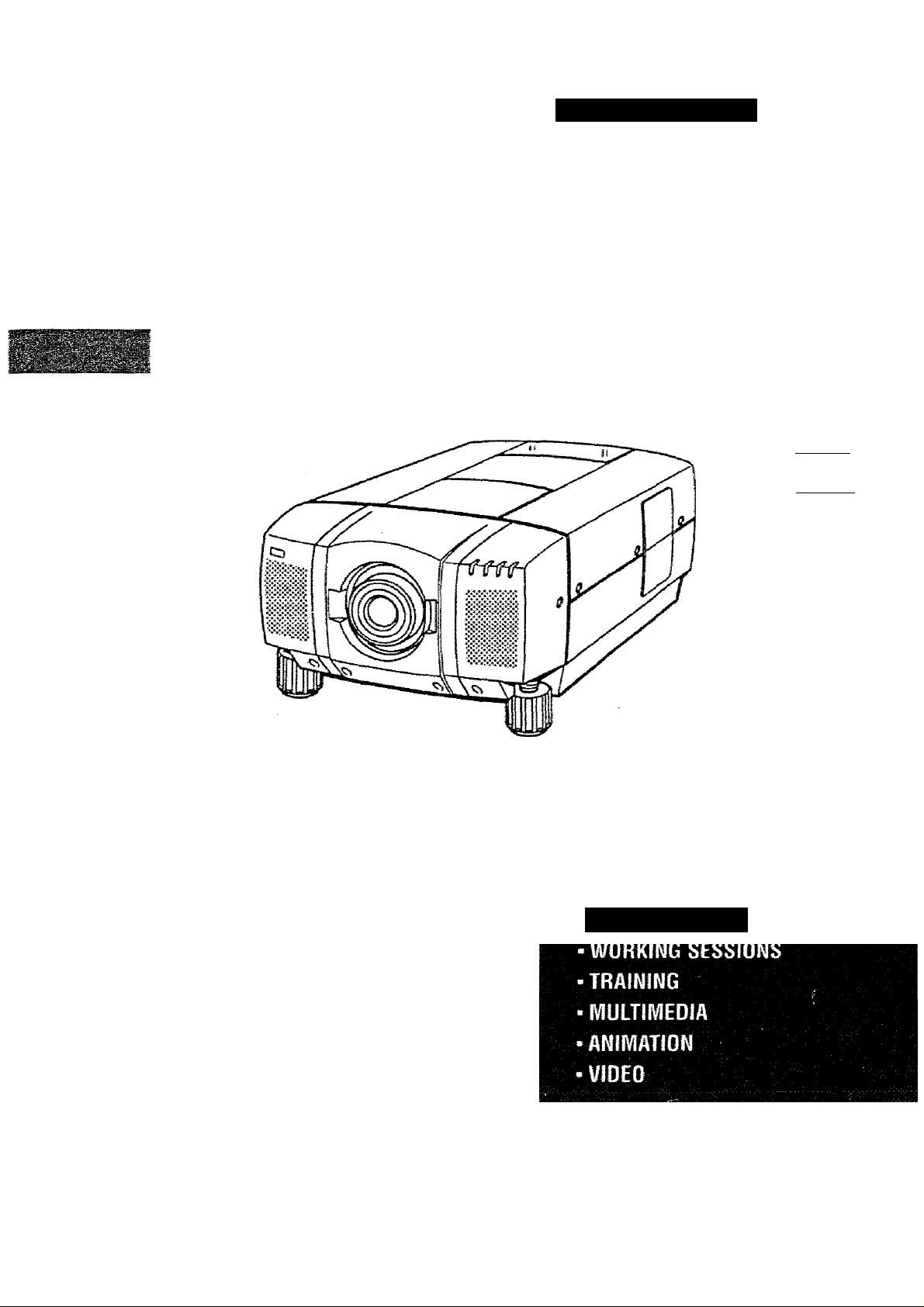
As the owner of a PRO AV 9310, you are probably eager to try out your new projector. Before you do, we
.suggest that you spend a little time reading this guide to familiarize yourself with the operating procedures, so
(that you will receive maximum satisfaction from the many features included in your new projector.
This user's guide will acquaint you with your projector's features. Reading it will help us too. Through the years,
we have found that many service requests were not caused by problems with our projectors. They were caused
by problems that could have been prevented, if the owner had followed the instructions in the guide.
You can often correct operating problems yourself. If your projector fails to work properly, see
"TROUBLESHOOTING” section on pages 52 ~ 53 and try the solutions marked for each problem.
c
WARNING:
TO REDUCE THE RISK OF FIRE OR ELECTRIC SHOCK, DO NOT EXPOSE THIS APPLIANCE TO RAIN OR
MOISTURE.
THIS Projector has a grounding-type AC line plug. This is a safety feature to bs sure that the plug wP
^ ■ the power outlet. Do not try to defeat this safety feature. '
Intense light source. Do not stare directly into the projection lens as possible eye damage could result.
Be especially careful that children do not stare directly into the beam.
SAFETY PRECAUTIONS
This Projector should be set In the way indicated. Never hang the projector, or fall down on its side.
It may result In fire hazard.
If the Projector will not be used for an extended time, unplug the Projector from the power outlet.
READ AND KEEP THIS USER’S GUIDE FOR LATER USE.
CAUTION
RISK OF ELECTRIC SHOCK
Ш
CAUTION: TO REDUCE THE RJSK OF ELECTRIC SHOCK, DO NOT REMOVE COVER (OR
BACK) NO USER-SERVICEABLE PARTS INSIDE. REFER SERVICING TO QUALIFIED
SERVICE PERSONNEL.
THIS SYMBOL 'ND:CA7ES THAT 0-bNGE4OUS VO_TAGE CGNSTiTLlTiNG A RiSK CF
à
ELECTilO Sr.CCK IS PRESENT WITHIN
THIS UNIT
DO NOT OPEN
A
A
THIS SYMBOL NDICATES "IHAT THERE ARE
VPORTANT OPERAT.NG AND MA frCNANCE
.NSTPUCtlCNS N THE JS.ER‘S GUIDE WIT
THIS UNIT.
— 2
Page 3
с
IMPORTANT SAFETY INSTRUCTIONS
All the safety and operating instructions should be read
'"■fore the product is operated.
Reawdfl of the instructions given here and retain them lor
later use. Unplug this projector from AC power supply
before cleaning. Do not use liquid or aerosol cleaners. Use
a damp doth for claaning.
Do not use attachments not recommended by the
manufacturer as they may cause hazards.
Do not place this projector on an unstable cart, stand, or
table. The projector may fall, causing serious injury to a
child or adult, and serious damage to the projector. Use
only with a cart or stand recommended by the
manufacturer, or sold with the projector. Wail or shelf
mounting should folow the manufacturer’s instructions,
and should use a mounting kit approved by the
manufacturer.
Do not expose this unit to rain or use near water... for
example, in a wet basement, near a swimming pool. etc...
Slots and openings in the back and bottom of the cabinet
are provided for ventilation, to Insure reliable operation of
the equipment and to protect tt from overheating.
openings should never be covered with cloth or other
' ■|.p«al, and the bottom opening should not be blocked by
the projector on a bed, sofa, rug, or other similar
surface. This projector should never be placed near or
over a radiator or heat register.
This projector should not be placed in a built-in Installation
such as a bookcase unless proper ventilation Is provided.
This projector should be operated only from the type of
power source indicated on the marking label If you are not
sure of the type of power supplied, consult your authorized
dealer or local power company.
Do not overload wall outlets and extension cords as this
cars result in fire or electric shock. Do not allow anything to
rest on the power cord. Do not locate this projector where
the cord may be damaged by persons walking on it.
a. When the power cord or plug is damaged or frayed,
b. If liquid has been spilled Into the projector.
c. tf the projector has been exposed to rain or water.
d. II the projector does not operate normally by following
the operating instructions. Adjust only those controls
that are covered by the operating instructions as
improper adjustment of other controls may result in
damage and wi oten require extensive work by a
qualified technician to restore the projector to norma!
operation.
e. If the projector has been dropped or the cabinet has
been damaged. _
I. When the projector exhibits a distinct change ln[||
performance-this indicates a need for service.
When replacement parts are required, be sure the service
technician has used replacement parts speciflecf by the
maïuffacturer that have the same characteristics as the
original part. Unauthorized substitutions may resuît in fire,
electric shock, or Injury to persons.
Upon completion of any service or repairs to this projector,
ask the service technician to perform routine safety checks
to determine that the projector is in safe operating
condition.
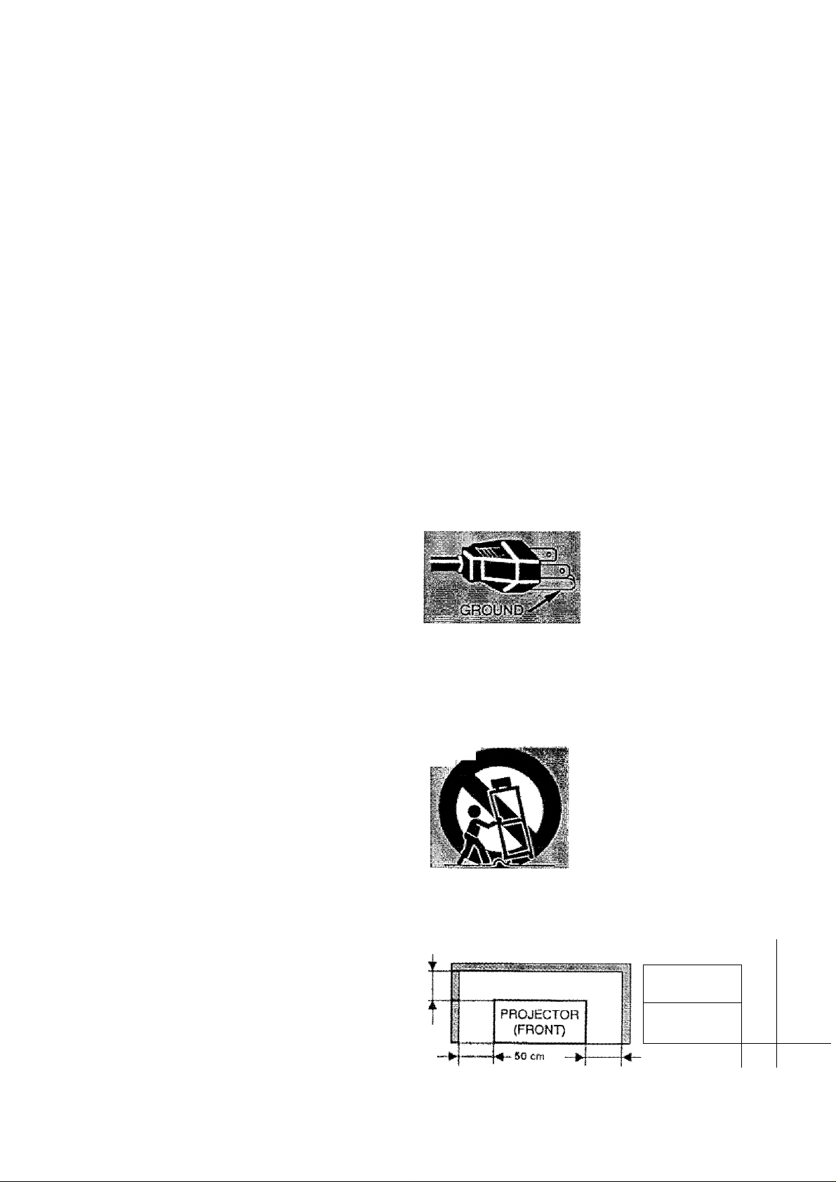
This projector is equipped with a
grounding type AC line plug.
Should you be unable to insert
the plug into the outlet, contact
your electrician. Do not defeat
the safety purpose of this
grounding type plug,
Follow all
projectors.
For added protection to the projector during a lightning
itorin, or whW: It is left ynattended and unused for tong
periods of tiiTMj, unplug it from the wall outlet This will
prevent dan^go duo to lightning and pcweritne surges.
warnings
and instructions marked on the
Ш -and carl combination
shouW b« ‘me¥^ ;Wlth care. Quick
»lops, lofeit, and m&mn
sufieceft
and cart согпЫш1Щ'Й,10<Ш^
Never push objects of any kind into this projector through
cabinet siots as they may touch dangerous voftage points
or short out parts that could result in a fire or electric
shock. Never spill liquid of any kind on the projector.
Do not attempt to service this projector yourself as opening
or removing covers may expose you to dangerous voltage
or other hazards. Refer ail servicing to qualified service |
*■ •sonnel, g
■’' Uhfwg this projector from wail outlet and refer servicing to
qualified service personnel under the following conditions;
if the projector is to be built into a compartmert m #№№irly
enclosed, the minimum distances must bo rrvMihtaihad,
Do not cover the ventilation slot on tho projeolor,
Heat build-up can reduce the service life of your
and can also be dangerous.
.......—...
PROJECTOR
SO cm —►
■3 —
.....
(SIDE)
..
--
1
$ WALl
5
1
fSO cir
Page 4

c
TABLE OF CONTENTS
3
!r _^ DDUCT!ON
COMPATIBILITY
IMAGE RESOLUTION
UNPACKING THE PROJECTOR
TRADEMARKS
POWER REQUIREMENT
DESCRIPTION
^SETTING-UP THE PROJECTOR
POSITIONING
ROOM LIGHT
LEVELING AND ELEVATING ADJUSTMENTS 7
VENTILATION
MOVING THE PROJECTOR
CONNECTING THE PROJECTOR
CONNECTING THE COMPUTER
Connecting an IBM-compatible desktop computer
Connecting a Macintosh desktop computer
Connecting an IBM-compatible laptop computer
Connecting a Macintosh PowerBook computer
CONNECTING THE VIDEO EQUIPMENT
0; ATION OF CONTROLS
TOP OF THE PROJECTOR
SIDE OF THE PROJECTOR
OPERATION OF REMOTE CONTROL
WIRELESS REMOTE CONTROL UNIT
WIRELESS/WIRED REMOTE CONTROL UNIT
CONTROL THE PROJECTOR
DIRECT OPERATION
MENU OPERATION
USING THE PROJECTOR
TO TURN ON THE PROJECTOR
TO TURN OFF THE PROJECTOR
DIRECT OPERATION
MODE SELECT
SOUND VOLUME ADJUSTMENT
SOUND MUTE FUNCTION
ZOOM ADJUSTMENT
PAGE
5
5 LENS SHIFT FUNCTION
5
5 NO SHOW FUNCTION
5
5 FREEZE PICTURE FUNCTION
6 AUTO IMAGE FUNCTION
7-8 MENU OPERATION 31-47
7
7 SOUND ADJUSTMENT 32
8
8
9-16
9-14 PICTURE IMAGE ADJUSTMENT
11 PICTURE SCREEN ADJUSTMENT 36
12 COMPUTER SYSTEM SELECT 37
13 COMPATIBLE COMPUTER SPECIFICATION 38
14 AUTO IMAGE FUNCTION 39
15-16 PICTURE IMAGE ADJUSTMENT
17-20 PICTURE POSITION ADJUSTMENT
17-18 PC ADJUSTMENT
19-20
21-25 OTHER FUNCTION SETTING
21-23
24-25 DISPLAY 47-48
26-28
26 REVERSE L/R
27-28 SPLIT WIPE
29-49 LAMP AGE 49
29 AIR FILTER CARE AND CLEANING 50
29 TEMPERATURE WARNING INDICATORS
29 LAMP REPLACEMENT 51
29 CLEANING THE LENS
30
30 TECHNICAL SPECIFICATIONS 54
30
FOCUS ADJUSTMENT
NORMAL PICTURE FUNCTION 30
P-TIMER FUNCTION
MODE SELECT
LANGUAGE ADJUSTMENT 32
MENU EXIT 33
COLOR SYSTEM SELECT 33
VIDEO SOURCE ADJUSTMENT
PICTURE SCREEN ADJUSTMENT 46
BLUE BACK
REVERSE T/B
TROUBLESHOOTING
PAGE
40 41
42-45
47-49
47-48
47-48
47-48
47-48
50
52
52-53
30
30
30'
30
30
30
31
34
35
__4_.
Page 5

INTRODUCTION
'The PRO AV 9310 is a multimedia projector that combines powerful and sophisticated features with easy-to-use, intuitive
^"'Tols. Built-in multimedia features include audio, a palette of 16.77 million colors and active matrix liquid crystal display
t. )) technology. The projector is ideal for high-performance business, training and imaging applications that demand
e^eptional color quality.
IbMt! I Y
The projector is compatible with many different types of personal computers and video devices, including:
• IBM-compatible computers, including laptops, up to 1280 x 1024 resolution.
• Apple Macintosh and PowerBook computers up to 1280 x 1024 resolution.
• Various VCRs, video disc players, video cameras. DVD players, satellite TV tuners or other AV equipment using any of
the worldwide video standards, including NTSC, NTSC4.43, PAL , PAL-M, PAL-N and SECAM.
IMAGE RESOLUTION
The resolution of the projector’s projected image is 1024 x 768. The projector displays computer images just as they
appear on your computer’s monitor. Screen resolutions between 1024 x 768 and 1280 x 1024 are compressed to 1024
X 768. The projector cannot display screen resolutions above 1280 x 1024. If your computer’s screen resolution is
higher than 1280 x 1024, reset it to a lower resolution before you connect the projector.
UNPACKING THE PROJECTOR
The projector comes with the parts shown listed below. Check to find all the parts are included, if any parts are missing,
contact an authorized dealer or service station.
D
1
• User’s Guide.
•AC Power Cord.
• Remote Control Transmitter Unit (Two Types) and batteries.
Lens Cover.
f Protective Dust Cover.
; \A Cable.
'#">r<3A/MAC Adapter.
• Mouse Cable for PS/2 port.
• Mouse Cable for serial port.
• Mouse Cable for ADB port.
'TRADEMARKS
• Apple, Macintosh, and PowerBook are trademarks or registered trademarks of Apple Computer, Inc.
• IBM and PS/2 are trademarks or registered trademarks of Internationa! Business Machines, tnc.
• Proxima is a registered trademark of Proxima Corporation.
• PRO AV is a trademark of Proxima Corporation.
• Other trademarks are the property of their respective owners.
POWER REQUIREMENTS
C
Your proje-itor uses nominal input voltages of 100-120 VAC or
200-240 VAC. The projector automatically selects the correct
Input voltage. The projector is designed to work with
single-phase power systems having a grounded neutral
conductor. To reduce the risk of electrical shock, do not plug into
any other type of power system.
Consult your authorized dealer or service station if you are not
sure what type of power is supplied to your building.
D
•5 —
supply cord (supplied) to
the projector,
Page 6
I
c
■>
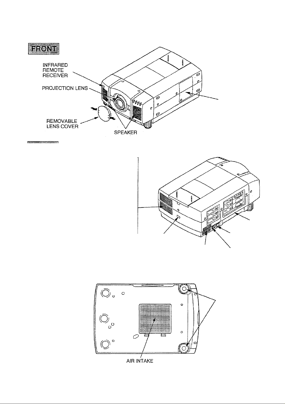
DESCRIPTION
LAMP
COVER
REAR
EXHAUST VENT
CAUTION HOTAIR I
Air blown from the exhaust vent is hot.
Observe the foiiowing when handling your
projector or choosing a location to install it.
• Keep heat-sensitive objects away from the
exhaust port.
• If you set the projector on top of a metallic
surface, the surface wiii become hot because
of the hot air exhaust. Be careful when
handling.
• Do not touch the cabinet near to the exhaust
vent area, and especially screws and metallic
parts. These parts will become hot while the
projector is used.
* •
BOTTOM
INFRARED
REMOTE
RECEIVER
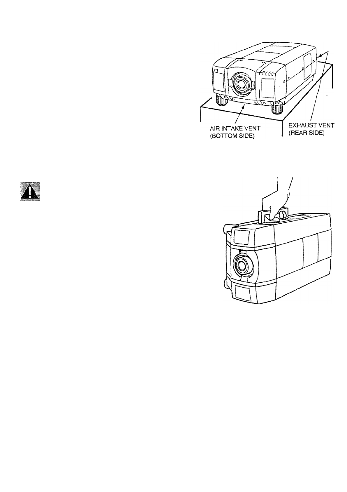
AIR INTAKE
VENT
CARRY HANDLE
MAIN ON/OFF
SWITCH
POWER CORD
CONNECTOR
VENT
LEVELING/ELEVATING
FEET
-6-
Page 7
c
'OSmONfNG:
A
SETTING-UP THE PROJECTOR
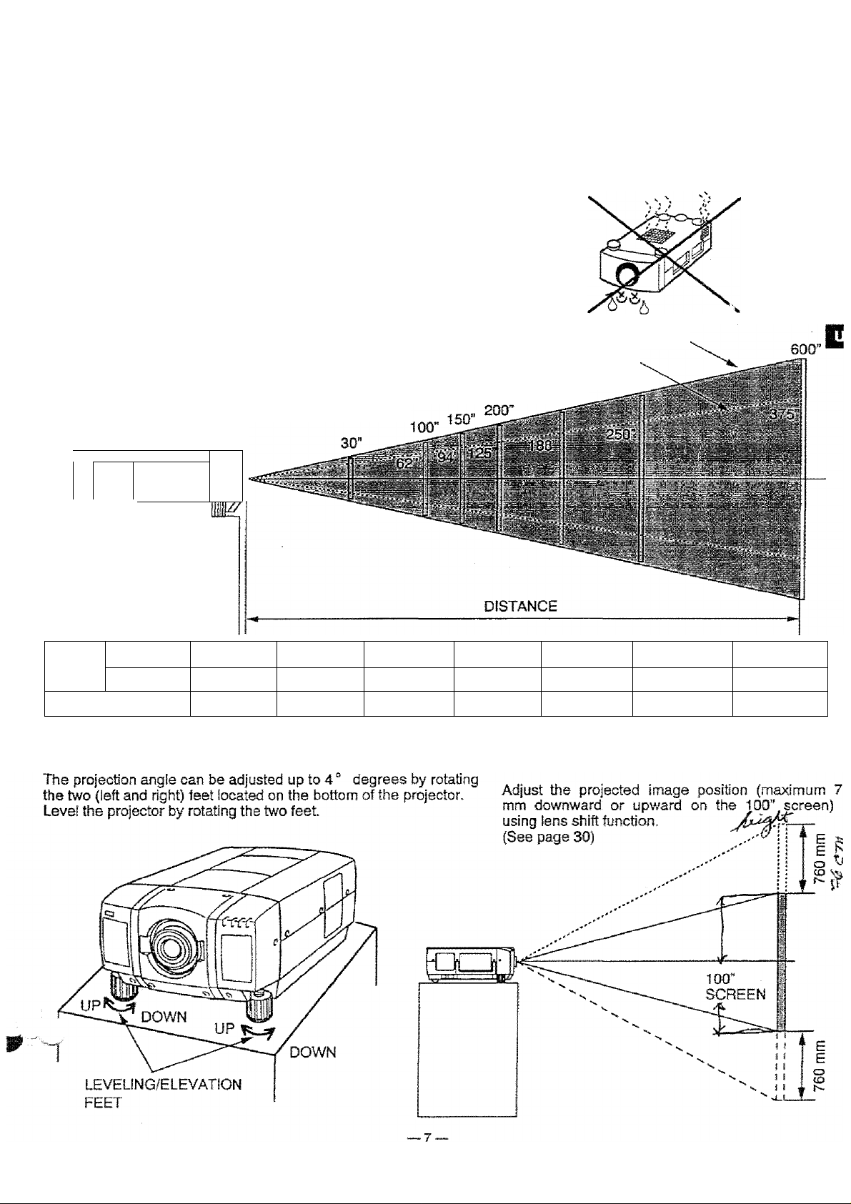
• This projector is basically designed to project on a flat projection surface.
• This projector can be focused from 3.6’ (1.1m) ~ 73.2’ (22,3m).
• Refer to the figure below as an example when positioning the projector to the screen.
THIS PROJECTOR SHOULD NEVER BE SET IN THE
WAY INDICATED. NEVER HANG THE PROJECTOR
UPSIDE DOWN. IT MAY RESULT IN FIRE HAZARD.
ROOM LIGHT
The projector should be placed in a room with
limited light. Picture quality will be directly
affected by lighting conditions.
I I
—
i oc5i
3 «
.............
1
0
—T
o
^ T
Screen
Size
Max. Zoom
Min. Zoom
Distance 3.6’(1.1 m)
LEVELING AND ELEVATING ADJUSTMENTS
30’ 100”
.......-.......
11.8’(3.6 m)
62” 94” 125" 188”
150’
17.7'(5.4m)
Maximum Zoom
Minirrium Zoom -
4CC
300"
200"
24.3’(7.4 m)
MOVE THE PROJECTED IMAGE POSITIC
300’
36.4’(11.1 m) 48.6’{14.8 m)
400"
250”
600"
375"
73.2’(22.3 m)
Page 8
VErsITILATION
This projector is equipped with a cooing fan to protect it from
overheating. Pay attention to the foftowing to ensure the
vf=ntiiation and avoid a possible risk of fire and malfunction.
Do not cover the vents with papers or other
materials.
A
Keep the rear grill at least 3.3’ (1m) away from any
object.
Make sure that there are no objects under the
projector. An object under the projector may prevent
the projector from taking the cooling air through the
bottom vent.
C
MOVING THE PROJECTOR
Use the carry handle when moving the projector.
Replace the iens cover and rotate the level)ng/eievation feet
fuiiy clockwise when moving toe projector to prevent damage to
the projector.
CAUTION IN CARRYING OR TRANSPORTING THE PROJECTOR
Do not drop or give a shock to the projector, otherwise damage or mulfunction may result.
When carrying the projector, use a Proxima recommended Carrying Case.
Do not transport the projector by using a courier or transport service in an unsuitable transport case. This may
cause damage to the projector. To transport the projector through a courier or transport service, use a Proxima
recommended Case.
For a carrying or transportation cases, contact a Proxima authorized dealer.
Page 9
CONNECTING THE PROJECTOR
^ NECTING TO THE COMPUTER INPUT 1 JACKS ЩМС TYPE x 5 )
Personal computers can be connected to the computer input (Red. Green, Blue, Horiz. Sync, and Vert. Sync.) on the
projector.
• Connect the computer to these jacks using the BNC cables {not provided).
CONNECTING TO THE COMPUTER INPUT 2 TERMINAL {HDB15-PIN (VGA)}
Personal computers can be connected to the HDB15-pin (VGA) terminal on the projector.
• Connect the computer to these terminals using the VGA cabie and VGA/MAC adapter (provided).
WARNING: For projectors, the VGA cable provided is designed to reduce RFI (Radio Frequency Interference) E
emissions. For regulatory compliance reasons, this cable must be used and must not be replaced by any
other cabie.
CONNECTING TO THE COMPUTER AUDIO INPUT JACKS (1 and 2>
• Connect audio outputs from your computer to these jacks using the RCA cable (not provided).
• If the audio input of the audio equipment is stereo, be sure to connect the right and left channels to the respective right
and left jacks.
• if the audio input of the audio equipment is monaural, connect it to the left jack.
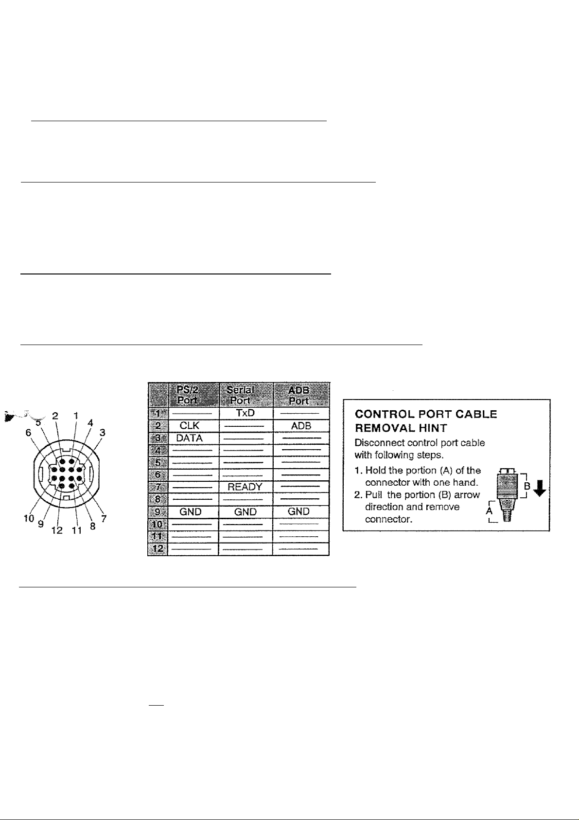
CONNECTING TO THE MULTI-POLE 12-PIN (CONTROL PORT) CONNECTORS (1 and 2)
• If you vwsh to control the computer with projector’s remote control unit, you must connect control port (PS/2. Serial or
ADB port) on your computer to projector's control port with cable, (three type of cables provided)
CONTROL PORT
CONNECTING TO THE MONITOR OUTPUT TERMINAL fHDB15-PlN (VGA»
This terminal contains the information that is viewed on the screen.
An external monitor can be connected to the HDB15-pin (VGA) terminal on the projector.
• Connect the monitor to this terminal using the VGA cable (not provided).
HJL3I5 PIN
\ о J о о о /
ут> )
Pin No./Stgnal
1 Red input
2 Green input
3 Blue input
4 Sense 2
5 Ground (Horiz. sync.)
6 Ground (Red)
7 Ground (Green)
8 Ground (Blue)
Pin No./Signal
9 Non Connect
10 Ground (Vert, sync.)
11 Sense 0
12 Sense 1
13 Horiz. sync.
14 Vert. sync.
15 Reserved
■9 —
Page 10
CONNECTING TO THE COMPUTER AUDIO MONITOR OUTPUT (VARIABLE) JACKS
These jacks will contain the audio information of the selected program source being viewed on the screen (Computer 1 or
Computer 2). If you have selected program source Computer 2 the audio signal connected to the Computer 2 audio input
jack will be available at the computer audio monitor output jacks, if you select program source *Video r or "Video 2, the
au signal connected to the Computer 1 audio input jack wifi be available at the computer audio monitor output jacks.
Cowect audio input from audio equipment to these jacks using the RCA cables.
• If the audio input of the audio equipment is stereo, be sure to connect the right and left channels to the respective right
and left jacks.
« If the audio input of the audio equipment is monaural, connect it to the left jack.
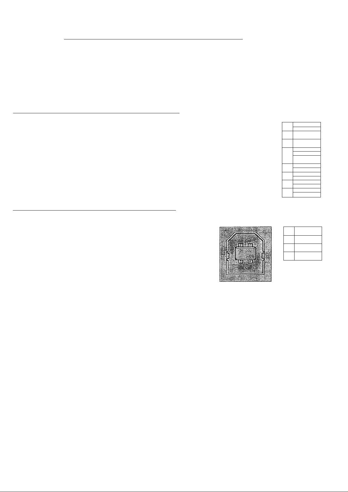
CONNECTING TO THE SERIAL PORT CDB9-PIN) TERMINAL
> If you control the projector by computer, you must connect a cable (not
provided) from your computer to this terminal.
CONNECTING TO THE USB PORT CONNECTORS H and 2)
This Projector is designed for connecting with USB Port of the computer or
peripheral equipment that is to be standard.
■ SERIAL PORT
□39 PIN
TERMINAL
■''‘=4321 "■
■' D O O O C ■'
\ 9 8/ S /
\ O C C O ,
V________
USB PORT
RxD
.2..
-3') TxD
Ground
5
6
T-
1
Vcc
-Data
2
-hData
3
4
Ground
■10-
Page 11
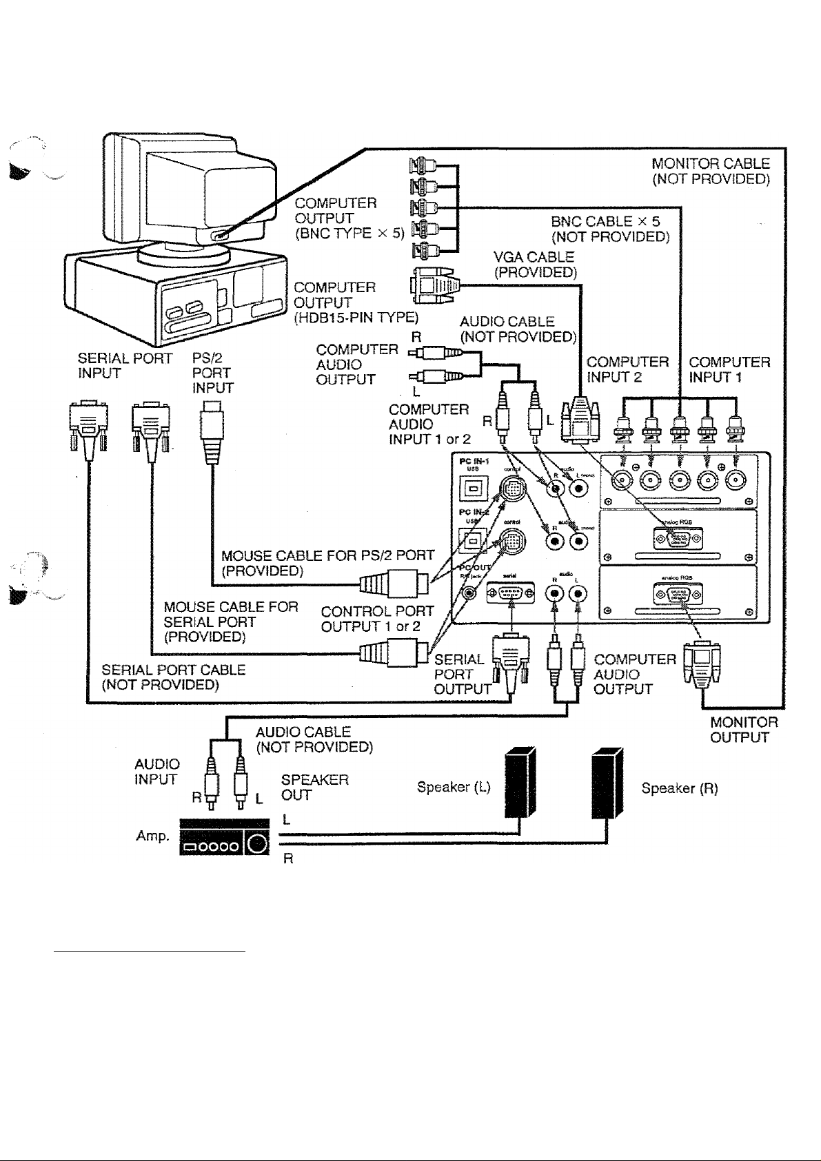
Connecting an IBM-compatible desktop computer
COMPUTER
I
NOTE: The hook up should be done as per the above illustration. After hook up, turn on the projector, monitor,
computer, in that order.
Connecting to Workstations
Please contact your Proxima reseller for details about PRO AV 9310 cable kits available for SUN, SGI and
'^ther workstations.
11
Page 12
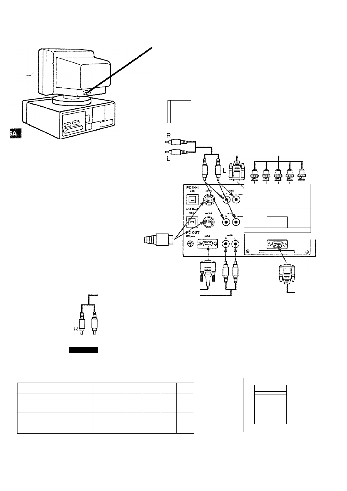
Connecting a Macintosh desktop computer
COMPUTER
COMPUTER
OUTPUT
(BNC TYPE X 5)
c
tm*
•e»«
I
COMPUTER
OUTPUT
£
(DB15-PIN TYPE)
ADB
PORT
INPUT
ADB
PORT
INPUT
COMPUTER
AUDIO
OUTPUT
COMPUTER
AUDIO R
INPUT 1 or 2
f
BNC CABLE X 5
(NOT PROVIDED)
VGA/MAC ADAPTER
(PROVIDED)
3
I
I
j
] [
\
VGA CABLE
(PROVIDED)
AUDIO CABLE
(NOT PROVIDED)
MONITOR CABLE
(NOT PROVIDED)
COMPUTER
INPUT 2
^ n
COMPUTER
INPUT 1
1
f e ?
—
___
i 0
MOUSE CABLE FOR ADB PORT
& !
__
—> ©;
(PROVIDED)
CONTROL PORT
OUTPUT 1 or 2
SERIAL
SERIAL PORT CABLE
(NOT PROVIDED)
PORT
OUTPUT
AUDIO CABLE
(NOT PROVIDED)
COMPUTER
AUDIO
OUTPUT
MONITOR
OUTPUT
AUDIO
INPUT
SPEAKER
L OUT
Speaker (L)
Speaker (R)
L
Amp.
laOQOO,:
R
Set the dip switches as shown in the table below depending on the
VGA/MAC ADAPTER
RESOLUTION MODE that you want to use before you turn on the
projector and computer.
HESOLUnON MODE
:3'MCCFifi4n 450,1
le'MODE 1832 624)
MODE ; 1024 ' 768'
- MODE .1152870)
SW1 i 3W2
ON I OFF
OFF I OFF
OFF OFF
ON ON
SW4
SV,'3
'OFF
SWc SvVC
OFF OFF
OFF
OFF OFF OFF ON.
ON
ON
OFF
OFF OFF
OFF
OFF
OFF
SW1-SW6
ON
E
OFF
ON
"^ygnggy
1 2 S 4 5 6
n cru
NOTE: The hook up should be done as per the above illustration. After hook up, turn on the projector, monitor,
computer, in that order.
— 12 —
Page 13
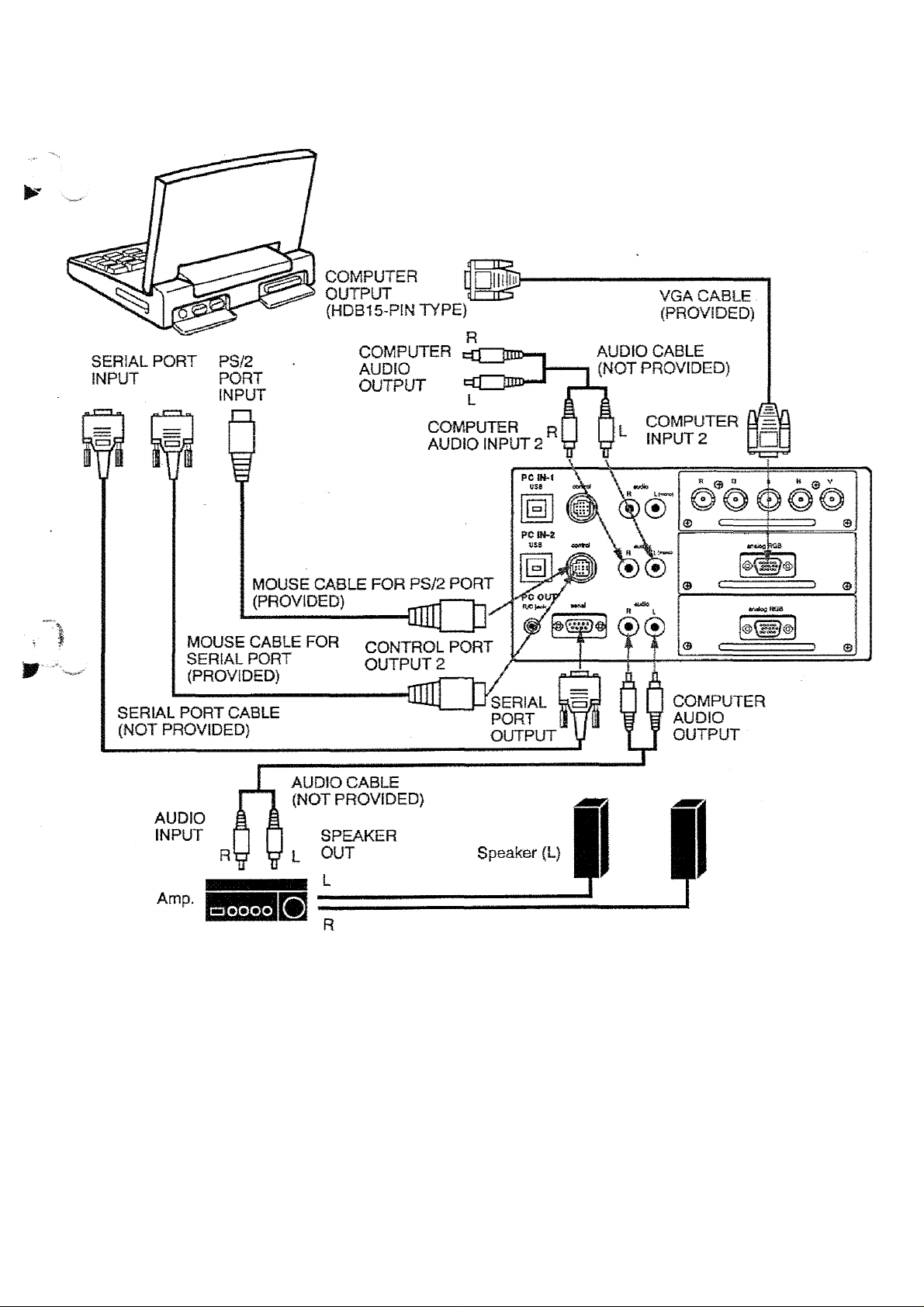
Connecting an IBM-compatible laptop computer
COMPUTER
Speaker (R)
NOTE: The hook up should be done as per the above illustration. After hook up, turn on the projector, computer, in
that order.
13-
Page 14
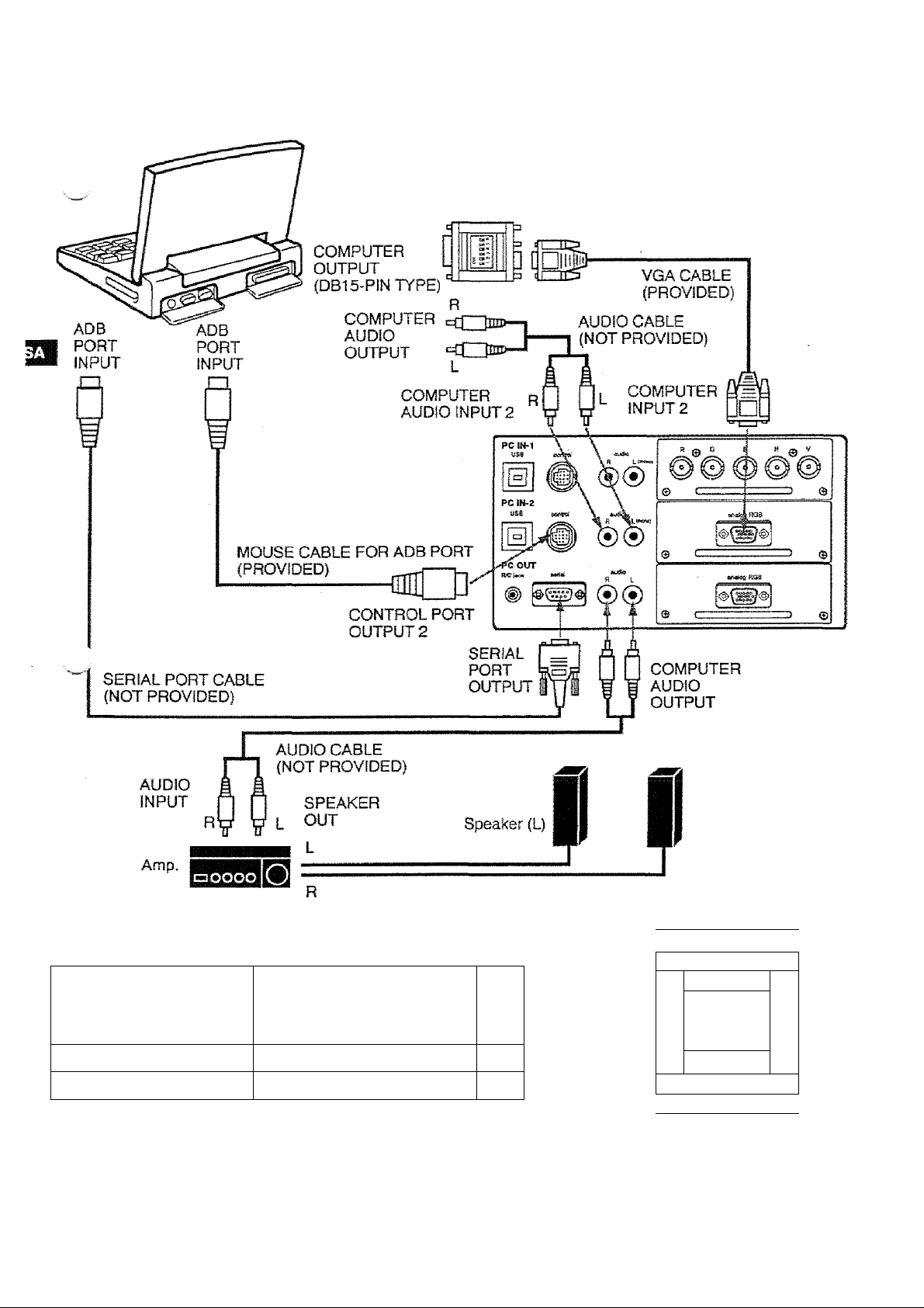
Connecting a Macintosh PowerBook computer
COMPUTER
The Macintosh PowerBook requires the use
of the PowerBook Video Adapter shipped
with the PowerBook.
VGA/MAC ADAPTER
(PROVIDED)
Set the dip switches as shown in the table below depending on the
RESOLUTION MODE that you want to use before you turn on the
projector and computer.
I RESOLUTION MODE
[ 13" MODE (640 '• 430)
jTe’ mode (832 ,X 624)
1 19'MCDi-0024 ■ 7GS)
or MODE (-.1o2 / 870)
The hook up should be done as per the above illustration. After hook up, turn on the projector, computer, in
that order.
'SW1 j SW2 Sy/31 SW#j.SW5
ON ' 1 OFF OFF 1 OFF OFF
OFF 1 OFF 1 OFF OFF | OFF
OFF ; OFF ' CFF ON,.. OFF
ON 1 ON ON ! CF - OFF
1 ! !
;sW6
OFF
ON
OFF
OFF
■14-
SW1-SW6
ON
B
OFF
Speaker (R)
VGA/MAC ADAPTER
n n
ON
''BBsaas
123456
Tin_ u u
Page 15

CONNECTING THE VIDEO EQUIPMENT (Video-Equipped Models Only)
CONNECTING TO THE VIDEO INPUT JACKS (1 and 2) BNC TYPE x 3
■’"nect to the video outputs of a VCR, video disc player, DVD player, video camera, satellite TV tuner or other AV
, ^ Tieni. Connect 'v4deo output from AV equipment to these jacks using the BNC cables.
The video input can be selected 3 type of the input. "COMPOSITE VIDEO", ”Y/C SEPARATE VIDEO” and COMPONENT
VIDEO {Y. Cb (B-Y), Or (R-Y)}.
When the video equipment with COMPOSITE VIDEO type output jack is used, to. select the ’Video” position by video
source select. When the video equipment with Y/C SEPARATE VIDEO type output jack is used, to select the ”Y, C”
position. When the video equipment with COMPONENT VIDEO {Y, Cb (B-Y), Or (R-Y)} type output Jack is used, to select
the "Y, Cb, Cr ” position. (See "VIDEO SOURCE SELECT" section on page 34).
CONNECTING S-VHS VIDEO INPUT JACKS 11 and 2)
The Video input includes an extra video input jack marked S-VIDEO to allow connection to an S-VHS format VCR thatj[
has separate Y/C video signals. The S-VIDEO Jack has priority over the VIDEO jack.
CONNECTING TO THE AUDIO INPUT JACKS (1 and 2)
Connect to the audio outputs of a VCR, video disc player, DVD player, video camera, satellite TV tuner or other AV
equipment. Connect audio output from AV equipment to these jacks using the RCA cables.
• If tile audio signal from the AV equipment is stereo, be sure to connect the right and left channels to the respective right
and left audioinput jacks.
• If the external audio signal is monaural, connect it to the left jack.
CONNECTING TO THE VIDEO MONITOR OUTPUT JACKS (BNC TYPE x 3)
These jacks will contain the video information of the selected program source being viewed on the screen (Video 1 or
Video 2). If you have selected program source Video 2 tiie video signal connected to the Video 2 video input jack will be
/ТгчаУаЫе at the video monitor output jacks. If you select program source “Computer 1“ or "Computer 2, the video signal
.4 :|inected to the Video 1 video input jack will be available at the video monitor output jacks,
ict video input from AV equipment to these jacks using the BNC cables.
CONNECTiONG TO THE S-VHS VIDEO MONITOR OUTPUT JACK
The Video monitor output includes an extra video input jack marked S-VIDEO to allow connection to an S-VHS format
VCR that has separate Y/C video signals. The S-VIDEO jack has priority over the VIDEO jack.
CONNECTING TO THE AUDIO MONITOR OUTPUT (VARIABLE) JACKS
These jacks will contain the audio information of the selected program source being viewed on the screen (Video 1 or
Video 2). If you have selected program source Video 2 the audio signal connected to the Video 2 audio input jack will be
available at the audio monitor output jacks. If you select program source “Computer 1” or "Computer 2, the audio signal
connected to the Video
Connect audio input from AV equipment to these jacks using the RCA cables.
1 audio input jack will be available at the audio monitor output Jacks.
•
• If the audio input of the audio equipment Is stereo, be sure to connect the right and left channels to the respective right
and left jacks.
♦ if the audio input of the audio equipment is monaural, connect it to the left jack.
15-
Page 16

Connecting the Video Equipment (Video-Equipped Models Only)
r VIDEO EQUIPMENT
DVD Player
Video Cassette Recorder
VIDEO Y C Cfa(B-Y) Cr(R-Y)
OUTPUT OUTPUT OUTPUT OUTPUT OUTPUT
(BNC) (BNC) (BNC) (BNC) (BNC)
Video Disc Piayer
Satellite
TV Tuner
SViDEO AUDIO
OUTPUT OUTPUT
Video Camera
VIDEO
INPUT
(BNC)
\_
Y C Cb (B-Y)
INPUT INPUT INPUT
(BNC) (BNC) (BNC)
Cr (R-Y)
INPUT
(BNC)
S-VIDEO
INPUT
/
AUDIO
INPUT
II
MONITOR
NOTE; The hook up should be done as per the above illustration. After hook up, turn on the projector, video equipment,
in that order.
— 16 —
SPEAKERS
AUDIO AMR
Page 17

OPERATION OF CONTROLS
TOP OF THE PROJECTOR
FRONT INDICATORS
FRONT
INDICATORS
TOP
CONTROLS
TOP CONTROLS
iamp temp,
warning
replace
17-
Page 18

LAMP REPLACEMENT INDICATOR
Light is orange when projection lamp is nearing end of service lite.
TEMPERATURE WARNING INDICATOR
©
Flashes red when internal projector temperature is too high.
READY INDICATOR
Light is green when projector lamp is ready to be turned on.
rm LAMP POWER INDICATOR
Light is dim when the projector is on.
Light is brightened when the projector is in stand-by mode.
VOLUME BUTTONS
©
Used to adjust volume.
mW ZOOM BUTTONS
1©
Used to operate power zoom lens.
FOCUS BUTTONS
Used to operate power focus system.
LENS SHIFT BUTTONS
©
Used to operate power lens shift.
LAMP POWER ON/OFF BUTTON
Used to turn projection lamp on or off.
I] MODE BUTTON
Used to select source.
(Computer 1, Computer 2, Video 1 or Video 2 input)
AUTO IMAGE BUTTON
©
Used to operate the AUTO IMAGE function.
MENU BUTTON
This button will activate the MENU operation.
Use this button, the POINT UP/DOWN/LEFT/RIGHT buttons and the SELECT button to make adjustments to the
projector's setting in MENU operation,
NORMAL BUTTON
Used to reset to normal picture adjustment preset by factory.
a POINT UP/DOWN/LEFT/RIGHT BUTTONS
To select an item on the MENU that you want to adjust. To select an item, move the arrow by pressing these
buttons (UP, DOWN, LEFT or RIGHT).
SELECT BUTTON
This button has different functions depending on when used. This button is used to execute the item selected, to
increase or decrease the values in certain items such as CONTRAST or BRIGHTNESS.
— 18 —
Page 19

SiDE OF THE PROJECTOR (CONNECT THE COMPUTER)
These terminals are changeable other type terminals.
If you want to change the terminals, contact your
authorized dealer or service station.
COMPUTER INPUT-1 JACKS (BNC TYPE X 5)
Used to connect a computer to the projector.
COMPUTER lNPUT-2 TERMINAL (VGA HDB15)
Used to connect a computer to the projector.
MONITOR OUTPUT TERMINAL (VGA HDB15)
Used to connect a monitor to the projector.
COMPUTER AUDIO INPUT-1 JACKS (R and L)
Used to connect an audio output from the computer
to the projector.
COMPUTER AUDIO INPUT-2 JACKS (R and L)
Used to connect an audio output from the computer to
the projector.
COMPUTER AUDIO MONITOR OUTPUT JACKS
(R and L)
Used to connect an audio input from audio equipment
to the projector.
CONTROL PORT-1 CONNECTOR
Used to connect a mouse cable to the projector.
CONTROL PORT-2 CONNECTOR
Used to connect a mouse cable to the projector.
USB PORT-1 CONNECTOR
Used to connect a computer to the projector.
USB PORT-2 CONNECTOR
Used to connect a computer to the projector.
SERIAL PORT TERMINAL (DB9)
Used to connect a computer to the projector.
WIRED REMOTE JACK
When using the wired remote control, connect
the remote cable to this jack.
19-
Page 20

SIDE OF THE PROJECTOR (CONNECT THE VIDEO EQUIPMENT)
(Video-Equipped Models Only)
VIDEO INPUT JACKS-1 (BNC TYPE x 3)
Used to connect a video source to the projector.
fey" S-VIDEO INPUT JACK-1
Used to connect a S-VHS video source to the projector.
@ AUDIO INPUT JACKS-1 (R and U)
Used to connect an audio source to the projector.
VIDEO INPUT JACKS-2 (BNC TYPE X 3)
Used to connect a video source to the projector.
S-VIDEO INPUT JACK-2
Used to connect a S-VHS video source to the projector.
@ AUDIO INPUT JACKS-2 <R and L)
Used to connect an audio source to the projector.
'll VIDEO MONITOR OUTPUT JACKS (BNC TYPE x 3)
Permits video connection to a monitor.
ЙЙ VIDEO MONITOR (S-VIDEO) OUTPUT JACK
Permits S-VHS video connection to a monitor.
•j AUDIO MONITOR OUTPUT JACKS (R and L)
Permits audio connection to a monitor.
-20-
Page 21

( OPERATION Of REMOTE CONTROL (Wireless)
- ■ ’"his remote control unit is not only able to operate the projector but
usabie as a wireless mouse for a PC. One pointing pad and
ir ■tv.^^lick buttons are used for wireless mouse operation.
Wireless mouse is usabie when PC mouse pointer is displayed on
the screen. When the menu or indicator of the projector is
displayed on the screen instead of the PC mouse pointer, the
wireless mouse cannot be used.
NOTE: To use the unit as a PC wireless mouse, connect the
projector to the PC with the attached cable. Signals from
the projector are transmitted to the PC, enabling the remote
control unit of the projector to be used as a PC wireless
mouse. (Refer to ’’CONNECTING THE PROJECTOR” in
pages 9 to 14 for the connection.)
D
FRONT
SIDE
_21 —
Page 22

MODE BUTTON
Used to seiect source. (Computer 1, Computer 2, Video 1 or Video 2 Input)
LAMP POWER ON/OFF BUTTON
o
Used to turn the projection lamp on or off.
VOLUME BUTTONS
Used to adjust volume.
Fi« ZOOM BUTTON
Used to select power zoom lens adjust.
P-TIMER BUTTON
©
Used to operate the P-TIMER function.
fì FOCUS BUTTON
a
Used to seiect focus adjust.
NO SHOW BUTTON
Used to change the screen into black image.
SOUND MUTE BUTTON
©
Used to mute sound.
Q LENS SHIFT BUTTON
Used to select power lens shift.
II FREEZE BUTTON
©
Use this button to freeze on-screen image.
AUTO IMAGE BUTTON
©
Used to operate the AUTO iMAGE function.
MENU BUTTON
©
This button will activate the MENU operation. Use this button, the POINT UP/DOWN/LEFT/RIGHT button and the
SELECT (REAR CLICK) button to make adjustments to the projector’s setting in MENU operation.
NORMAL BUTTON
©
Use to reset to normal picture adjustment preset by factory.
SI POINTING PAD
©
(POINT UP/DOWN/LEFT/RIGHT BUTTON)
When in use as a remote for the projector.
To select an item on the MENU that you want to adjust. To select an item, move the arrow by pressing the pad
upward, downward, leftward or rightward.
Used to operate power zoom lens, power focus system or power fens shift by pressing the pad either upward or
downward.
When in use as a wireless mouse
Used to move the pointer. The pointer is moved according to the direction you are pressing.
FRONT CLICK BUTTON
©
This button has the same function as the right button in a PC mouse. Pressing this button does not affect any
operation when in MENU mode.
SELECT (REAR CLICK) BUTTON
©
When in use as a remote for the projector.
This button has different functions depending on when used. This button is used to execute the item selected, to
increase or decrease the values in certain items such as CONTRAST or BRIGHTNESS.
When In use as a wireless mouse
This button has the same function as the left button in a PC mouse.
— 22-
Page 23

REMOTE CONTROL BATTERY INSTALLATION
S!' ‘e - talij' ai imo l'.o
a
Note; For correct polarity (+ and -
terminai), be sure the battery
terminals are in contact with
the pins in the compartment.
USING THE REMOTE CONTROL UNIT
Point the remote control toward the projector (Receiver window) whenever pressing the buttons. Maximum operating
range for the remote control is about 16.4’ (5 m) and 60 “ front and rear of the projector.
A
To insure safe operation, please observe the foliowing precautions:
• Use (2) AA type alkaline batteries.
• Change two batteries at the same time.
• Do not use a new battery with a used battery.
• Avoid contact with water.
• Do not drop the remote control unit
• If batteries have leaked on the remote control, carefully wipe the case
clean and load new batteries.
■23-
Page 24

( OPERATION OF REMOTE CONTROL (Wlreless/WIred) )
A WIRED REMOTE JACK
When using the wired remote control, connect the remote
cable to this jack.
MODE BUTTON
Used to select source.
(Computer 1, Computer 2, Video 1 or Video 2 Input)
LAMP POWER ON/OFF BUTTON
©
Used to turn projection lamp on or off.
VOLUME BUTTONS
o
Used to adjust volume.
lO
c
ZOOM BUTTONS
Used to operate power zoom tens.
FOCUS BUTTONS
Used to operate power focus system.
SOUND MUTE BUTTON
e
Used to mute sound.
A LENS SHIFT BUTTONS
Used to operate power tens shift.
A P-TIMER BUTTON
Used to operate the P-TfMER function.
il AUTO IMAGE BUTTON
m
Used to operate the AUTO IMAGE function.
NO SHOW BUTTON
Used to change the screen into black image.
MENU BUTTON
This button will activate the MENU operation.
Use this button, the POINT UP/DOWN/LEFT/RIGHT buttons and the SELECT button to make adjustments to the
projector’s setting in MENU operation.
POINT UP/DOWN/LEFT/RIGHT BUTTONS
To select an item on the MENU that you want to adjust. To select an item, move the arrow by pressing these
buttons (UP. DOWN. LEFT or RIGHT).
FREEZE BUTTON
Use this button to freeze on-screen image.
SELECT BUTTON
This button has different functions depending on when used. This button is used to execute the item selected, to
increase or decrease the values in certain items such as CONTRAST or BRIGHTNESS.
•1 NORMAL BUTTON
Used to reset to normal picture adjustment preset by factory.
— 24 —
Page 25

REMOTE CONTROL BATTERY INSTALLATION
2 ^ Diiiie'ics‘i'!:o the
compc-rtriieni:.'
Note: For correct polarity (+
and - iermina!), be sure the
battery terminals are in
contact with the pins In the
compartment
:n
/
The remote control unit can be used as wireless or wired remote control,
— -P --I ■ •f—I--,* , -F.-v,'*-• - .-p* »iV-,r
.,U5JNp^THE REMOTE CONTROL UNIT (wireless);
Point the remote control toward the projector (Receiver window) whenever pressing the buttons. Maximum operating
range lor the remote control is about 16.4’ (5 m) and 60 ° front and rear of the projector.
USING THE REMOTE CONTROL UNIT (wired)j
Connect a remote control cable to R/C jacks located on the wireless/wired remote control unit and the side of
projector.
To insure safe operation, please observe the following
precautions;
A
• Use (2) AA type alkaline batteries,
• Change two batteries at the same time.
• Do not use a new battery with a used battery.
• Avoid contact with water.
• Do not drop the remote control unit.
• If batteries have leaked on the remote control,
carefully wipe the case clean and load new batteries.
■25-
the
Page 26

c
CONTROL THE PROJECTOR
The projector has two types of operation: DiRECT OPERATION and MENU OPERATION. DIRECT OPERATION allows
yoii to operate the projector by using one button without showing the MENU. In MENU OPERATION mode, you display
r IS where you can adjust the projector’s settings. Follow the instruction for each control.
DIRECT OPERATION
ADJUST ITEM
LAMP POV/ER ON.'OFF
SIODLSLLLCI MOD:_
SOUND VOLIiMF
SOUND MUTE
ZOOM
FOCUS
LENS SHIFT
NORMAL PICTURE
:> SHOW
P-TIMER
TOP CONTROL OP
THE PROJECTOR
.AMP PEWEP ON OFF
VOl > IME (+; and ( - ) VOLUME {+) and ( - ) VOLUME {+) and ( - )
NOT AvAll ABLE MUTE
■ 1 O’'"! 1 , 1
FOCUS
(A:a-ri( )
1 ENS SHIFT
(.A) and {V}
NORMH_
NOT AVAILABLE
NOT AVAILABLE
WIRELESS WIRED
REMOTE CONTROL
LAMP POWER ON-OFF
MODE
ZOOM
(A)andCy)
FOCUS
(A)and(V)
LENS SHIFT
(A)and(y)
NORMAL
NO SHOW NOSHOW
P-TIMER
WIRELESS
REMOTE CONTROL
LAMP POWER ON-OFF
MODE
MUTE
ZOOM
POINT (UP/DOWN)
FOCUS
POINT (UP/DOWN)
LENS SHIFT
POINT (UP/DOWN)
NORMAL
P-TIMER
FREEZE PICTURE
AUTO IMAGE
NOT AVA'„ABLE FREEZE
AUTO IMAGE
AUTO IMAGE
FREEZE
AUTO IMAGE
-25-
Page 27

MENU CPERATtON
ADJUST ITEM
.лООЕ SELECT.
TOP CONTROL OF
THE PROJECTOR
MENU
POINT LEFT/RIGHT
SELECT
POINT UP/DOWN
SELECT
1. COMPUTER/VIDEO MODE
ADJUST ITEF/
SOUND
SOUND VOLUME
TREBLE
BASS
BUILT-IN SP.
SOUND MUTE
LANGUAGE
SETTING
BLUE BACK
DISPLAY
REVERSE T Б
REVERSE H ^
SPLIT WIPE
LAMP AGE
TOP CONTROL OF
THE PROJECTOR
MENU
POINT LEFT/RIGHT
SELECT
POINT UP/DOWN
SELECT
MENU
POINT LEFT/RIGHT
SELECT
POINT UP/DOWN
SELECT
WIRELESSAVIRED
REMOTE CONTROL
MENU
POINT LEFT/RIGHT
SELECT
POINT UP/DOWN .
SELECT
w:rele3S/Wired wireless
REMOTE CONTROL REMOTE CONTROL
MENU
POINT LEFT/RIGHT
SELECT
POINT UP/DOWN
SELECT
MENU
POINT LEFT/RIGHT
SELECT
POINT UP/DOWN
SELECT
W RELESS
REMOTE CONTROL
MENU
POINT (LEFT/RIGHT)
SELECT (REAR CLICK)
POINT (UP/DOWN)
SELECT (REAR CLICK)
MENU
POINT (LEFT/RIGHT)
SELECT (REAR CLICK)
POINT (UP/DOWN)
SELECT (REAR CLICK)
MENU
POINT (LEFT/RIGHT)
SELECT (REAR CLICK)
POINT (UP/DOWN)
SELECT (REAR CLICK)
MENU EXIT
MENU
POINT LEFT/RIGHT
SELECT
2. VIDEO MODE (Video Equipped Models Only)
ADJUST ITEM
COLOR SYSTEM
VIDEO SOURCE
VIDEO
Y Cb. Cr
PICTURE IMAGE
COLOR
V/HITE BALANCE
CONTRAST
BRIGHTNESS
3HARPNESS
PICTURE SCREEN
WIDE
REGULAR
TOP CONTROL OF
THE PROJECTOR
MENU
POINT LEFT/RIGHT
SELECT
POINT UP/DOWN
SELECT
MENU
POINT LEFT/RIGHT
SELECT
POINT UP/DOWN
SELECT
MENU
POINT LEFT/RiGHT
SELECT
V/IRELESSAVIRED \ V/iRELESS
REMOTE CONTROL REMOTE CONTROL
MENU
POINT LEFT/RIGHT
SELECT
POINT UP/DOWN
SELECT
MENU
POINT LEFT/RIGHT
SELECT
POINT UP/DOWN
SELECT
MENU
POINT (LEFT/RIGHT)
SELECT (REAR CLICK)
MENU
POINT (LEFT/RIGHT)
SELECT (REAR CLICK)
POINT (UP/DOWN)
SELECT (REAR CLICK)
MENU
POINT (LEFT/RiGHT)
SELECT (REAR CLICK)
POINT (UP/DOWN)
SELECT (REAR CLICK)
— 27 —
Page 28

3. COMPUTER MODE
ADJUST ITEM
OMPUTER SYSTEM
AlJTO IMAGE
FINE SYNC
1 TOTAL DOTS
1 POSITION
PICTURE IMAGE
FINE SYNC
TOTAL DOTS
Y/HITE BALANCE
CONTRAST
BRIGHTNESS
PICTURE POSITION
TOP CONTROL OF '.VIRELESS V/IRED
THE PROJECTOR ' REMOTE CONTROL
MENU
POINT LEFT/RIGHT
SELECT
POINT UP/DOWN
SELECT
MENU
POINT LEFT/RIGHT
SELECT
POINT UP/DOWN
SELECT
MENU
POINT LEFT/RIGHT
SELECT
POINT UP/DOWN
SELECT
MENU
POINT LEFT/RIGHT
SELECT
POINT
LEFT/RfGHT/UP/DOWN
SELECT
MENU
POINT LEFT^IGHT
SELECT
POINT UP/DOWN.
SELECT
MENU
POINT LEFT/RIGHT
SELECT
POINT UP/DOWN
SELECT
MENU
POINT LEFT/RIGHT
SELECT
POINT UP/DOWN
SELECT
MENU
POINT LEFT/RIGHT
SELECT
POINT
LEFT/RIGHT/UP/DOWN
SELECT
WIRELESS
REMOTE CONTROL
MENU
POINT (LEFT/RIGHT)
SELECT (REAR CLICK)
POINT (UP/DOWN)
SELECT (REAR CLICK)
MENU
POINT (LEFT/RIGHT)
SELECT (REAR CLICK)
POINT (UP/DOWN)
SELECT (REAR CLICK)
MENU
POINT (LEFT/RIGHT)
SELECT (REAR CLICK)
POINT (UP/DOWN)
SELECT (REAR CLICK)
MENU
POINT (LEFT/RIGHT)
SELECT (REAR CLICK)
POINT
(LEFT/RIGHT/UP/DOWN) ‘
SELECT (REAR CLICK)
PC ADJUSTMENT
PICTURE SCREEN
TRUE
EXPAND
COMPRESSED
PANNING
NOTES:
1. The MENU, once activated, will not disappear unless you choose MENU EXIT operation. If you switch to DIRECT
operation by pressing a DIRECT operation button while in MENU mode, the menus will disappear and the MENU
operation will end.
2. You can use the REMOTE CONTROL UNIT or the TOP CONTROL OF THE PROJECTOR to operate the MENU
operation.
MENU
POINT LEFT/RIGHT
SELECT
POINT UP/DOWN
SELECT
MENU
POINT LEFT/RIGHT
SELECT
POINT UP/DOWN
SELECT
POINT
LEFT/RIGHT/UP/DOWN
MENU
POINT LEFT/RIGHT
SELECT
POINT UPyDOWN
SELECT
MENU
POINT LEFT/RIGHT
SELECT
POINT UP/DOWN
SELECT
POINT
LEFT/RIGHT/UP/DOWN
MENU
POINT (LEFT/RIGHT)
SELECT (REAR CLICK)
POINT (UP/DOWN)
SELECT (REAR CLICK)
MENU
POINT (LEFT/RIGHT)
SELECT (REAR CLICK)
POINT (UP/DOWN)
SELECT (REAR CLICK)
POINT
(LEFT/RIGHT/UP/DOWN)
■28-
Page 29

c
USING THE PROJECTOR
'O TUm ON THE PROJECTOR
the projector to a source (Computer, VCR, Video Camera, Video Disc Player, etc.) using the appropriate
terminals on the side of the projector (See "CONNECTING THE PROJECTOR" section on pages 9-16).
Connect the projector's AC power cord into a wall outlet and turn the MAIN ON/OFF switch (located on the side of the
projector) to the ON position. The LAMP POWER indicator wilt light RED, the READY indicator will light GREEN,
Press the LAMP POWER ON/OFF button on the remote control unit or on the
projector to ON. The LAMP POWER indicator light wit! dim and the cooling fans will
operate. The wait display appears on the screen and the count-down starts
{30-29-28-...1), The signal from the source appears after 30 seconds.
30
i-
CAUTION:
THIS PROJECTOR USES A METAL-HALIDE ARC LAMP. TO EXTEND THE LIFE OF THE LAMP, ONCE
YOU HAVE TURNED IT ON, WAIT AT LEAST 5 MINUTES BEFORE TURNING IT OFF.
NOTE: TEMPERATURE WARNING INDICATOR flashes red, the projector will automatically turn off.
Wait at least 5 minutes before turning the projector on.
If the TEMPERATURE WARNING INDICATOR continues to flash, follow the procedures beiow:
(1) . Press LAMP POWER ON/OFF button to OFF.
(2) . Check the air fitter for dust accumulation.
(3) . Remove dust with vacuum cleaner (See "AIR FILTER CARE AND CLEANING” section on page 50.)
(4) . Press LAMP POWER ON/OFF button to ON.
E
'I If the TEMPERATURE WARNING INDICATOR still continues to flash, call your authorized dealer or service
station.
» TO TURN OFF THE PROJECTOR
Press the LAMP POWER ON/OFF button on the remote control unit or on the projector.
The "Power off ?” appears on the screen. Press again the LAMP POWER ON/OFF
button to turn OFF the projector. The LAMP POWER indicator will light bright and
READY indicator will turn off. The cooling fans wil! operate for 1 minute after the
projector is turned off. (During this "cooling down” period, the projector cannot be turned
on.) The READY indicator will iight green again and the projector may be turned on by
pressing ffie LAMP POWER ON/OFF button. To power down completely, turn the MAIN
ON/OFF switch (located on the side of the projector) to the OFF position.
DIRECT OPERATION MODE SELECT
Press the MODE button (located on remote control unit or on the projector) to select
Computer 1, Computer 2, Video 1 or Video 2 Input. The "Computer 1”, "Computer 2“,
"Video r or "Video 2” display will appear on the screen for a few seconds.
Computer i v
Computer 2
Video ^ .
-29-
yy®o 2
Page 30

SOUND VOLUME ADJUSTMENT
Press the VOLUME buttons (located on remote control unit or on the projector) to
adjust the volume. The volume display will be displayed on the screen for a few
seconds.
Pressing volume (+) will increase volume and increase the number on the screen.
P! ing volume (- ) will decrease volume and decrease the number on the
sche^n.
i
Ц|| Volume
- -i
i 32
SOUND MUTE FUNCTION
Pressing the MUTE button on the remote control unit will mute audio. Press the
MUTE button again to restore audio to its previous level. The mute display will be
displayed on the screen for a few seconds.
J< M
: On ■
■
----
ZOOM ADJUSTMENT (Top control and Wirefess/WIred remote control unit)
Press the ZOOM (+) or ) button to obtain your desired picture size. For a larger picture,
■ press (+) and for a smaller picture, press (-).
"zoom adjustment (Wireless remote control unit)
Press the ZOOM button and press POINT UP/DOWN button(s) to obtain your desired
picture size. The Zoom display will be displayed on the screen for a few seconds. For a
larger picture, press (UP) and for a smaller picture, press (DOWN).
FOCUS ADJUSTMENT (Top control and Wireless/Wired remote control unit)
Press the FOCUS (+) or (-) button for a sharper, crisper picture.
FOCUS ADJUSTMENT (Wireless remote control unit)
Press the FOCUS button and press POINT UP/DOWN button(s) to obtain a sharper,
crisper picture. The Focus display will be displayed on the screen for a few seconds.
Focus
LENS SHIFT FUNCTION (Top control and Wireless/Wired remote control unit)
Press the LENS SHIFT (+) or (~) button to obtain your desired screen position.
Lens shift
LENS SHIFT FUNCTION (\Mreiess remote control unit)
Press the LENS SHIFT button and press POINT UP/DOWN button(s) to obtain your
de d screen position. The Lens shift display will be displayed on the screen for a few
seib.„,.Hcis.
NORMAL PICTURE FUNCTION
The normal picture level is factory preset on the projector and can be restored anytime
by pressing the NORMAL button (located on remote control unit or on the projector). The
’’Normar display will be displayed on the screen for a few seconds.
Normal
NO SHOW FUNCTION
Press the NO SHOW button on the remote control unit. The screen will change into black
image and the ”N0 SHOW" is displayed on the screen for a few seconds.
This funcfion is cancelled when the NO SHOW button is pressed again or any other
function button is pressed.
'N'p' sHow-'-;|
P-TIMER FUNCTION
Press the P-TIMER button on the remote control unit The timer display ”00:00” appears
on the screen and the timer starts to count the time (00:00-59:59).
Press again the P-TIMER button to stop the timer. Then press the P-TIMER button to
cancel the P-TiMER function.
00:01
FREEZE PICTURE FUNCTION
Press the FREEZE button on the remote control unit, and the picture wifi remain on-screen. This function is cancelled
when the FREEZE button is pressed again or any other function button is pressed.
I
I
NOTE: Your computer or video equipment is not affected by this function, and will continue to run.
AUTO IMAGE FUNCTION
Press the AUTO IMAGE button on the remote control unit or on the projector. The item(s) indicated "ON” in the AUTO
IMAGE FUNCTION are adjusted automatically.
It r e items in AUTO IMAGE FUNCTION are "OFF”, AUTO IMAGE SETTING display appears. If you wish to operate
the>-^TO IMAGE FUNCTION, perform the steps 3 - 9 of "AUTO IMAGE FUNCTION” section on page 39.
■Э0 —
Page 31

MENÜ OPERATION
In MENU OPERATION mode, you can adjust the projector. You can use the TOP CONTROL OF THE PROJECTOR
- -the REMOTE CONTROL UNIT.
CONTROL OF
WIRELESS REMOTE
CONTROL UNIT
MODE SELECT
You can select a mode from MAIN MENU display among computer 1, computer 2, video 1 and video 2.
1. Press the MENU BUTTON and the MAIN MENU DISPLAY dialog box will appear.
2. Press the POINT LEFT/RIGHT BUTTON (s) to select Computer or Video and press the SELECT (REAR CLICK)
BUTTON. Another dialog box MODE DISPLAY will appear.
3. Press the POINT DOWN BUTTON and a red arrow will appear.
4. Move the arrow to the mode you want (computer 1, computer 2, video 1 or video 2) to use by pressing the POINT
UP/DOWN BUTTON(s) and then press the SELECT (REAR CLICK) BUTTON.
MAIN MENU DISPLAY
2orrrLi-r
f i
Ccmpt.'to~.1
Vceo fCocpLlOi'
jm ! □ 1
Video t
V de.-) 2
M
V.Jj.
1
; Auto j'.j V d'jo
MODE DISPLAY
VGA •
MODE DISPLAY
-Y ) -:p : 1
MAIN MENU DISPLAY
l,ltl
iil|i
• "1
1
t.
P®
rc
Ì-' .•
English I -'jlflll
•31
Page 32

VIDEO SOURCE SELECT (VIDEO MODE) Video-Equipped Models Only
1, Connect the video equipment to the PROJECTOR, and turn them on projector first.
2, Set MODE SELECT to "VIDEO MODE”.
Press the MENU BUTTON and the MAIN MENU DISPLAY dialog box wit! appear.
Press the POINT LEFT/RiGHT BUTTON(s) to select VIDEO SOURCE and press the SELECT (REAR CLICK)
BUTTON. Another dialog box VIDEO SOURCE DISPLAY will appear. The current VIDEO SOURCE is displayed
In the window.
5. Press the POINT DOWN BUTTON and a red arrow will appear.
6. To change the current VIDEO SOURCE, press the POINT UP/DOWN BUTTON(s) to move the arrow to a
desirable video source and then press the SELECT (REAR CLICK) BUTTON.
7. The setting changed remains effective until the MAIN ON/OFF switch is turned off.
MAIN MENU DISPLAY
VÌDEO SOURCE
DISPLAY
4-,i
=’"el eh
— 34 —
Page 33

PICTURE IMAGE ADJUSTMENT (VIDEO MODE) Video-Equipped Models Only
Picture adjustments have been preset at the factory. If you want to change the setting, operate the projector as
follows.
. Press the MENU BUTTON and the MAIN MENU DISPLAY dialog box will appear.
W. Press the POINT LEFT/RiGHT BUTTON(s) to select IMAGE and press the SELECT (REAR CLICK) BUTTON.
Another dialog box IMAGE ADJUST DISPLAY will appear. This shows the current picture settings.
3. In this dialog box. you can adjust the settings by increasing or decreasing the levels shown as numbers. The
items and the range of the levels that you can adjust are summarized in the table below.
4. Press the POINT DOWN BUTTON and a red arrow will appear.
5. Move the arrow to an item that you want to adjust by pressing the POINT UP/DOWN BUTTON{s). ■
6. To increase the level, point the arrow to A and then press the SELECT (REAR CLICK) BUTTON. To decrease
the level, point the arrow to V and then press the SELECT (REAR CLICK) BUTTON.
7. You may want to store the settings in the memory so that you can recall them later. To store the settings, move
the arrow to Stored and then press the SELECT (REAR CLICK) BUTTON. When you have stored the settings,
"OK T is displayed for confirmation.
8. Move the arrow to Yes and then press the SELECT (REAR CLICK) BUTTON. The stored settings are
permanently held even if the MAIN ON/OFF is switched off.
9. To quit the MENU, move the arrow to Quit and then press the SELECT (REAR CLICK) BUTTON.
10. If you do not want to store the settings, move the arrow to Quit and then press the SELECT (REAR CLICK)
BUTTON. The settings changed remains effective until the MAIN ON/OFF switch is turned off.
11. To recall the settings from the memory that you have stored, move the arrow to Reset and then press the
SELECT (REAR CLICK) BUTTON. When you have reset the settings, "OK ?" is displayed for confirmation. Move
the arrow to Yes and then press the SELECT (REAR CLICK) BUTTON. You can adjust the settings again if
needed.
NOTE: TINT' will be skipped in the PAL. SECAM, PAL-M and PAL-N mode.
MAIN MENU DISPLAY
3cTF:Ff77¡3n_
_________________________
IMAGE
”■ Я.1Г'Т p}-i -P=
Ф Ci-lrr- - ■
Ф Ti-^
Wh te bñ^ar
IMAGE
ADJUST DISPLAY
'iCcnfr'ast
TABLE OF PICTURE IMAGE ADJUSTMENT
'Rec
Greon
V Bl.;«
. 32'”
1_32 _
31
' 3?.
} 3^ i
nqlish
•ЧГ
ж
OK
^ 1 -
i' ÑI ■
COLOR
■ WHITE BALANCE (R/G B)
CONTRAST
BRIGH'^NESS
SHARPNESS SOFTER
DECREASES
1
MORE PURPLE
Ш
DECREASES
'£
LIGHTER
i
Ш
DARKER
“Й
-35-
63 INCREASES
0 63
0
INCREASES
63
MORE GREEN
63
DEEPER
BRIGHTER
63
SHARPER
31
Page 34

PICTURE SCREEN ADJUSTMENT (VIDEO MODE) Video-Equipped Models Only
This projector has the Wide function, which enables you to view a wider video image.
WIDE function
's projector is able to project not only a norma! video image (with 4x3 aspect ratio), but also a wider video image
compressing 4x3 image. This feature enable you to enjoy watching pictures like cinema images. You can switch
either to WIDE or to REGULAR screen mode.
1. Press the MENU BUTTON and the MAIN MENU DISPLAY dialog box will appear.
2. Press the POINT LEFT/RIGHT BUTTON(s) to select SCREEN and press the SELECT (REAR CLICK) BUTTON.
Another dialog box SCREEN ADJUST DISPLAY will appear.
3. Press the POINT DOWN BUTTON and a red arrow will appear.
4. To switch to '’Wide” mode, move the arrow to Wide by pressing the POINT UP/DOWN BUTTON(s) and then press
the SELECT (REAR CLICK) BUTTON.
5. To switch to "Regular” mode, move the arrow to Regular by pressing the POINT UP/DOWN BUTTON(s) and then
press the SELECT (REAR CLICK) BUTTON.
6. The "Wide" settings remains effective until the MAIN ON/OFF switch is turned off.
MAIN MENU DISPLAY
•i:.)) I [(
-36-
Page 35

COMPUTER SYSTEM SELECT (COMPUTER MODE)
This projector is adjustable to different types of computer display signals based on VGA, SVGA. XGA or SXGA (See
"COMPATIBLE COMPUTER SPECIFICATIONS" on the next page). If you set MODE SELECT to "COMPUTER”, the
- '^'-olector will automatically process the incoming signal and project the proper image without any special setting.
.hough this will work in most cases, you may be required to manually set the projector for some computer signals. If
'The computer image is not reproduced properly, try the following procedure and switch to the computer display mode
that you want to use,
1. Connect the COMPUTER to the PROJECTOR, and turn them on projector first.
2. Set MODE SELECT to "COMPUTER MODE (1 or 2)This shows the current display mode initially detected by the
projector in the system window. And "Current mode" display appears.
NOTE: 1. if the projector cannot discriminate or detect the input signal from the computer, the "Go PC adj.” display
appears.
NOTE: 2. If no input signal from the computer, the “No signal” display appears on the screen. '
3. Press the MENU BUTTON and the MAIN MENU DISPUY dialog box will appear.
4. Press the POINT LEFT/RIGHT BUTTON(s) to select SYSTEM arid press the SELECT (REAR CLICK) BUTTON.
Another dialog box COMPUTER SYSTEM DISPLAY will appear.
5. Press the POINT DOWN BUTTON and a red arrow will appear.
6. If you want to change the current display mode, move the arrow by pressing the POINT UP/DOWN BUTTON(s) to
select one of the modes.
7. Press the SELECT {REAR CLICK) BUTTON to charrge the display mode.
8. To quit the MENU, move the arrow to Quit and then press the SELECT (REAR CLICK) BUTTON.
I
'"C-C" :ucO
COMPUTER
SYSTEM
D'SPL/AV
CURRENT MODE
DISPLAY
PC ADJUSTMENT
SYSTEM
1 VGA 1 I
VGA:
v'GA2
' VGA3.
VOA4
r:>-
. - *.
MAIN MENU DISPLAY
When the mark {O ) is displayed as BLACK,
computer system mode will be available on the
next page. Move an arrow to the mark (O )
and press the SELECT (REAR CLICK)
BUTTON to show computer system mode
described on the ne)d: page.
vCA-
VGA3
W3A4_'
Modi' 1
^'OUlJ 2
Enoi sn I
„i
i
*
.
This is a special function that may be used wherr a computer image is not reproduced properly. (See the pages 42 45 for more detail.)
•37-
Page 36

COMPATIBLE COMPUTER SPECIFICATIONS
I ON-SChEbN
PFSOl.'J i ION
H-rraq.
(khz
v„,CA1 640 X 480 31.47
V'GA2
VGA3
VGA-I D-.o;* 100
VGA5
VGA6
720 •- 400 _
6-40 X 400
31 -17
31.47
37.85
640 X 480
37.86
540 480 37.50
MACLC13 640 X 480 34.97 66.60
13 CfO ^ 180
PC98 640 X 400
FM TOWNS
G40 400
SVGA1 800 X 600
SVGA2
800' 6C0
SVGA3 800 X 600
SVGA4
800 ' 600
SVGAS 800 X 600
3.5 do 24, S3
56.42
24.3S ' 55.40
35.156
56.25
37.58 CO 32
46.875
J -1
48.03
75.00
85.06
T2,19
SVGAo ECO X GOO 37.90 61,03
SVGA’
800 X 600
34.50
55 58
«^VGAS 800; COO 38.CC
/3A9
5.3A1 :■
SVG All
SVr.Ar’
M.AC 16
XCA1
800 X 500
38.60
800 X 600 47 90 71.92
800 ■ 300
800 ' 600
32.70
38.00
332 G24 49,~2
1024 708
48 45 6100
.XGA2 1024 • 768 68.677
XGA3 1C24' 76S
XGA4
s3A )
1024 -■ 7G8
1024 768
XGA6 1024 \ 768
X'-A7
XGA8
1024 768
1024 X 768
60.023
56 47
60 31
48.50
44.00
63.48
60.31
5- 09
60.51
74 55
34 997
■ 75.03
70 07
'¿.92
5jC2
54 58
79.35
59.88
70 C9
7U 09
74.38
72.81
'0.00
66.6.^
ON-bCP.iZLN
DISPLAY
XGA9
^f'AIO
XG.-'-11
XGA12
XGA13
XGA14
MAC 15 102'- ■ 768
SXGA1
SXGA2 1230 :C24 G2.50
i
SX3A4
SXGA5
SXGA6
b\J'-7 1280 1024 31.13
SXGAS
SI : *J
SXGA10
sxG.A-:i
SXGA12
SXGA13
S,\GA14 '2E0 ■ 1024
SXGA15
SXGA'6
.SXOA17 115'’
SXGA18
SXG.A-9
M.A321 1152 ■ ??0
MAO
.PESC UTION
1024X 768 36.00
-C?4 763 C.'^Ot 77.37
1024 > 768 61. oc
"C24 - 7b8
1024 '■
1024
1152 X
1230 .
1280 •
'230 10^4 63.74 50 01
12S0 A 1024
1280 X 1024
.1280, X 1024
1280 X 960
1152 X 900
1152 X 900
1280 - 1024 50.00 IF. -fl
1230 X
1280 A ■C24
1230 - '624
1280 X
1280 ■ 9~ '
70S
768 47.G0 ; 53 30
864 C-4.2C 7 40
IC24
1024 -33.34
1624
900
1024
'I f'-ec
35.522
46.GG
60.24 7t..0y
i 63.90
71.69 67.19
63.98
.79 976 7.5.025
60.00 60.00
61.20
71.40
50 00
63.37 .
73.97
61 65
!3 .'13
33.79
63.33
75.C.1
V.--n^r,
i.Hri
87.17
(Interlace)
75.70
■83 C6
.'i";.e'acc)
i 53..20
58 60
CO. 00
59 93
76.107
60.02
■ 65.2-0
75.60
; ace'
94.00
;l“to' acc;
GO.C •
72.00
66 00
8":.7C
(1 "i'.t“’’ fiCi'
C0.1S
75.03
75.0.3
Specifications are subject to change without notice.
MAC
1280 X1024
80.00
75.08
NOTE: This projector can accept the signal from all computers with the above mentioned V, H-Frequency and iess
than 135 MHz Dot Clock.
-38-
Page 37

AUTO IMAGE FUNCTION (COMPUTER MODE)
The Auto image function is provided to automaticaKy adjust Fine sync., Tota! dots and Screen position for most
computers.
Press the MENU BUTTON and the MAIN MENU DISPLAY dialog box will appear.
T2. Press the POINT LEFT/RiGHT BUTTON(s) to select AUTO IMAGE and press the SELECT {REAR CLICK}
BUTTON. Another dialog box AUTO IMAGE SETTING DISPLAY will appear.
3. Press the POINT DOWN BUTTON and a red arrow wifi appear.
4. Move the arrow to an item(s) you want to adjust by pressing the POINT UP/DOWN BUTTON(s).
5. Change the setting "On", press the SELECT (REAR CLICK) BUTTON.
6. Move the arrow by pressing the POINT UP/DOWN BUTTON(s) to select "Go!" and then press the SELECT
(REAR CLICK) BUTTON. The auto image function is started now. It will take about 10 seconds.
7. To store the settings, move the arrow to Stored and then press the SELECT (REAR CLICK) BUTTON. When you
have stored the settings, "OK?" is displayed for confirmation.
8. Move the arrow to Yes and then press the SELECT (REAR CLICK) BUTTON. The stored settings are
permanently held even if the MAIN ON/OFF is switched off.
9. To quit the MENU, point to Quit and then press the SELECT (REAR CLICK) BUTTON.
10. This setting is temporarily effective until you turn off the projector or change the input signal.
NOTE; The fine sync., total dots and screen position of same computers may not be fully adjusted with the "Auto
Image Function”. In that case, use the "Picture Image” and/or "Picture Position” adjustments (see pages 40 ~
41) to make fine-adjust them after the "Auto Image Function” is executed.
Ml
Ì
AUTO IMAGE SETTING
DISPLAY
^ VGA ' 1.
MAIN MENU DISPLAY
AUTO IMAGE
i'llW. '-i p s» 4|))) o-ji.sh
[ Pine’sync./: ! o
;■-Total’ccis -.U Cn
■39-
Page 38

PICTURE IMAGE ADJUSTMENT (COMPUTER MODE)
Picture adjustments have been preset at the factory, !f you want to change the setting, operate the projector as
follows.
■■ Press the MENU BUTTON and the MAIN MENU DISPLAY dialog box will appear.
Press the POINT LEFT/RIGHT BUTTON(s) to select IMAGE and press the SELECT (REAR CLICK) BUTTON.
'"^Another dialog box IMAGE ADJUST DISPLAY will appear. This shows the current picture settings.
3. Jn this dialog box, you can adjust the settings by increasing or decreasing the levels shown as numbers. The
items and the range of the levels that you can adjust are summarized in the table beiow.
4. Press the POINT DOWN BUTTON and a red arrow will appear.
5. Move the arrow to an item that you want to adjust by pressing the POINT UP/DOWN BUTTON(s).
6. To increase the level, point the arrow to Д and then press the SELECT (REAR CLICK) BUTTON. To decrease
the level, point the arrow to V and then press the SELECT (REAR CLICK) BUTTON.
7. You may want to store the settings in the memory so that you can recall them later. To store the settings, move
the arrow to Stored and then press the SELECT (REAR CLICK) BUTTON. When you have stored the settings,
"OK ?" is displayed for confirmation.
8. Move the arrow to Yes and then press the SELECT (REAR CLICK) BUTTON. The stored settings are
permanently held even if the MAIN ON/OFF is switched off.
9. To quit the MENU, move the arrow to Quit and then press the SELECT (REAR CLICK) BUTTON.
10- If you do not want to store the settings, move the arrow to Quit and then press the SELECT (REAR CLICK)
BUTTON. The settings changed remains effective until the MAIN ON/OFF switch is turned off.
To recall the settings from the memory that you have stored, move the arrow to Reset and then press the
11
SELECT (REAR CLICK) BUTTON. When you have reset the settings, ”OK ?“ is displayed for confirmation. Move
the arrow to Yes and then press the SELECT (REAR CLICK) BUTTON. You can adjust the settings again if
needed.
MAIN MENU DISPLAY
IMAGE
.¿¿"‘V III!
IMAGE ADJUST
DISPLAY
NOTE: The projector may not reproduce
a proper image for some SXGA [
signals.
Since SXGA (1280 X 1024) j. ■
image is converted to XGA
(1024 X 768) image by partial
scan, some lines and dots of the
image do not appear.
Some video noise of flicker on
this compressed SXGA image
cannot be eliminated even though
you try to make a Fine sync
adjustment.
TABLE OF PICTURE IMAGE ADJUSTMENT
FINE SYNC
TOTAL DOTS
lllll
.
p » H:
Fngllsn
;V Г . ^
tfjcta'dots'., j 1 "аз
^ №.'10'ba'anco
Red.! 7? t
Hue.
.0 Conc'-ast, Г t
Ъ Btijii* bci ' ^ t
Adjust the picture as necessary to eliminate ^
flicker from the display.
The number of the total dots in one horizontal period. Adjust the
number to match your PC image.
3^ t
•Г’ ‘k'v' '
.C _) ' (
tlio—) ,
' -...............................-
__
'Ф*
CK 7
1
WHITE BALANCE (R'G □>
CONTRAST
BRIGHTNESS DARKER 0 ■-» 63 BRIGHTER
DECREASE 0 63 INCREASE
LIGHTER 0 ► 63 DEEPER
-40-
C
Page 39

PICTURE POSITION ADJUSTMENT (COMPUTER MODE)
1. Press the MENU BUTTON and the MAIN MENU DISPLAY dialog box will appear.
2. Press the POINT LEFT/RIGHT BUTTON{s) to select POSITION and press the SELECT (REAR CLICK) BUTTON.
Another dialog box POSITION SETTING DISPLAY will appear.
ress the POINT DOWN BUTTON and a red arrow will appear.
4. Move the arrow to a desirable direction t or 4- } by pressing the POINT LEFT/RIGHTAJP/DOWN
BUTTON(s) and press the SELECT (REAR CLICK) BUTTON to a desirable picture position.
5. You may want to store the settings to the memory so that you can recall them later. To store the settings, move
the arrow to Stored and then press the SELECT (REAR CLICK) BUTTON. When you have stored the settings,
"OK ?" is displayed for confirmation.
6. Move the arrow to Yes and then press the SELECT (REAR CLICK) BUTTON. The stored settings are
permanently held even if the MAIN ON/OFF is switched off.
7. To quit the MENU, move the arrow to Quit and then press the SELECT (REAR CLICK) BUTTON.
8. if you do not want to store the settings, move the arrow to Quit and then press the SELECT (REAR CLICK)
BUTTON. The settings changed remains effective until the MAIN ON/OFF switch is turned off.
9. To recall the settings from the memory that you have stored, move the arrow to Reset and then press the SELECT
(REAR CLICK) BUTTON. When you have reset the settings, ”OK ?" is displayed for confirmation. Move the arrow
to Yes and then press the SELECT (REAR CLICK) BUTTON. You can adjust the settings again If needed.
MAIN MENU DISPLAY
FOSmON
F~l 1
POSITION SETTING
DISPLAY
■41
Page 40

PC ADJUSTMENT
This projector can automatically detect most display signals from most persona! computers currently distributed.
However, some computers adopt a special signal format which is different from the standard one and the projector
"'■^.nnot detect it. If this happens, the projector cannot reproduce a proper image. And a flickering picture, a
n-synchronized picture, a non-centered picture or a skewed picture may be projected instead.
For those non-standard formats, this projector is provided with PC ADJUST, enabling you to precisely adjust several
parameters to match with the input signal format. The projector has eight independent memory areas where you can
store the parameter you have set. This enables you to recaithe setting for a specific computer when you need it.
1. Press the MENU BUTTON and the MAIN MENU DISPLAY dialog box will appear.
2. Press the POINT LEFT/RIGHT BUTTON(s) to select PC ADJUST and press the SELECT (REAR CLICK}
BUTTON. Another dialog box ” Where to reserve” will appear,
3. In this dialog box, you will select one of the memory areas from among "Mode 1" to "Mode 8”. If parameters have
been previously set and stored in the memory, the status "Stored” will appear on the corresponding row. If not,
"Free" will appear.
4. Press the POINT DOWN BUTTON and a red arrow will appear.
5. Move the arrow to one of the "Modes” (Free position) where you want to store the parameters by pressing the
POINT UP/DOWN BUTTON(s). Press the SELECT (REAR CLICK) BUTTON to select it.
NOTE; If "Stored" appears in all Modes, no new PC parameter data can be stored, in this case, clear the PC
parameter data using the Mode free Function,
ill
y'iijo fC:
VGA 1
ViA!N MENU DISPLAY
hhi-
111
l|l|!'
— 42-
Page 41

6. Another dialog box ’PC ADJUSTMENT DISPLAY 1” will appear and the parameter data for the Mode you have
selected is shown in this dialog box.
7. The parameters will be filled with the data determined by the projector according to the present signal Input.
8. The function of the parameters and their values are summarized in the table below.
. Move the arrow to an item that you want to adjust by pressing the POINT UP/DOWN BUTTON (s).
"To. To increase the level, point the arrow to A and then press the SELECT (REAR CLICK) BUTTON, To decrease the
level, point the arrow to V and then press the SELECT (REAR CLICK) BUTTON.
11. If you want to store the settings in the memory, move the arrow to Stored and press the SELECT (REAR CLICK)
BUTTON. When you have stored the settings, "OK ?" is displayed for confirmation. Move the arrow to Yes and
then press the SELECT (REAR CLICK) BUTTON .
12. To recall the parameter data before setting, move the arrow to Reset and then press the SELECT (REAR CLICK)
BUTTON. When you have reset the settings, "OK T is displayed for confirmation. Move the arrow to Yes and then
press the SELECT (REAR CLICK) BUTTON . You can adjust the settings again if needed.
13. To quit the MENU, move the arrow to Quit and then press the SELECT (REAR CLICK) BUTTON. n
14. If you quit the MENU without storing the settings in the memory, the parameter data you changed will not be kept "
15. The stored settings are permanently held even if the MAIN ON/OFF is switched off.
16. Adjust the data such as a "Clamp". "Heighf and "Width" if needed, move the arrow by pressing the POINT
UP/DOWN BUTTON(s) to select (T). Press the SELECT (REAR CLICK) BUTTON.
PC ADJUST
I
TOTAL LINES
TOTAL DOT’S
! pj:'!j|!i5nF
PC ADJUSTMENT
DISPLAY 1
ITEM FUNCTiON
The number of the total vertical lines. Adjust the number to match your PC image.
The number of the total dots in one horizontal period. Adjust the number to match your PC
image.
~r G iSi'
HORIZONTAL
VERTICAL
Adjustment of the horizontal picture position. When the image is not centered on the
screen, adjust this.
Adjustment of the vertical picture position. When the image is not centered on the screen,
adjust this.
Page 42

17. Another dialog box ”PC ADJUSTMENT DiSPLAY 2” will appear and the parameter data for the Mode you have
selected is shown in this dialog box.
18. Move the arrow to an item that you want to adjust by pressing the POINT UP/DOWN BUTTON (s).
19. To increase the level, point the arrow to A and then press the SELECT (REAR CLICK) BUTTON. To decrease the
levef, point the arrow to V and then press the SELECT (REAR CLICK) BUTTON.
■w. if you want to store the settings in the memory, move the arrow to Stored and press the SELECT (REAR CLICK)
BUTTON. When you have stored the settings, "OK ?" is displayed for confirmation. Move the arrow to Yes and
then press the SELECT (REAR CLICK) BUTTON .
21. To recall the parameter data before setting, move the arrow to Reset and then press the SELECT (REAR CLICK)
BUTTON. When you have reset the settings, ”OK ?” is displayed for confirmation. Move the arrow to Yes and then
press the SELECT (REAR CLICK) BUTTON . You can adjust the settings again if needed.
22. To quit the MENU, move the arrow to Quit and then press the SELECT (REAR CLICK) BUTTON.
23. If you quit the MENU without storing the settings in the memory, the parameter data you changed wii: not be kept.
24. The stored settings are permanently held even if the MAIN ON/OFF is switched off.
■fr . _ PC ADJUST
V d":
T'j
C "I’i)
En;: sn )
Mode 1
£''-'-1 I
To'aldo's "
PC ADJUSTMENT
DISPLAY 2
hcr.:ji‘J
Ve'tioal;
.Clamo
ITEM
CLAMP
HEIGHT
WIDTH
h<.;gn.|
FUNCTION
Adjustment of the clamp level. When the image has a dark bar, try this adjustment.
Expanding or compressing level for the vertical direction.
Expanding or compressing level for the horizontal direction.
— 44-
Page 43

yOPE FREE
The Mode free lunciion is provided to confirm or clear the parameter data produced by PC ADJUST.
-■ Press the MENU BUTTON and the MAIN MENU DISPLAY dialog box will appear.
’ress the POINT LEFT/RIGHT BUTTON(s) to select PC ADJUST and press the SELECT (REAR CLICK)
''“BUTTON. Another dialog box ” Where to reserve” will appear.
3. Press the POINT DOWN BUTTON and a red arrow will appear.
4. Move the arrow to one of the "Modes" (Stored position) that you want to confirm by pressing the POINT UP/DOWN
BUTTON(s). Press the SELECT (REAR CLICK) BUTTON. Another dialog box "PC ADJUSTMENT DISPLAY” will
appear.
5. To quit the MENU, point to Quit and then press the SELECT (REAR CLICK) BUTTON.
6. To modify the parameter data, perform the steps 9 - 24 of PC ADJUSTMENT SECTION.
7. To clear the parameter data, move the arrow by pressing the POINT UP/DOWN BUTTON(s) to select Mode tree.
Press the SELECT (REAR CLICK) BUTTON. ”OK?” is displayed tor confirmation.
8. Move the arrow to Yes and then press the SELECT (REAR CLICK) BUTTON to clear the parameter data.
9. To quit the MENU, move the arrow to Quit and then press the SELECT (REAR CLICK) BUTTON.
MAIN MENU DISPLAY
. ' Cor.pulS'._____________^__________PC ADJUST
■ I
---
1 .
........
■-M_- - ' .-rI ' -
it Q' '-l!;!!^ :
P^A_p_JUST .
Wnere to reserve
Ml
English [■
i
1
■ PC ADJUST
'-i-
PC ADJUSTMEN; ■■
DISPLAY
OK ?
__
____
I&;
h ■ ij i''
No " , ;
■ 45 —
Page 44

PICTURE SCREEN ADJUSTMENT (COMPUTER MODE)
This projector has a picture screen resize function, which enables you to project the image size.
Input image
resolution
Less than XGA
(1024 X 768) image
XGA (1024 X 768)
image
More than XGA
(1024 X 768) image
True
Mode
n
None
Expand
Mode
m
None
None
Compressed
Mode
None
None
Panning
Mode
None
None
□
1. Press the MENU BUTTON and the MAIN MENU DISPLAY dialog box wifi appear.
2. Press the POINT LEFT/RIGHT BUTTON(s) to select SCREEN and press the SELECT (REAR CLICK) BUTTON.
Another dialog box SCREEN ADJUST DISPLAY will appear.
3. Press the POINT DOWN BUTTON and a red arrow will appear.
4. To switch to "Expand mode", move the arrow to Expand by pressing the POINT UP/DOWN BUTTON(s) and then
press the SELECT (REAR CLICK) BUTTON. The mode is changed "Expand".
5. To switch to "True mode", move the arrow to True by pressing the POINT UP/DOWN BUTTON(s) and then press
the SELECT (REAR CLICK) BUTTON. The mode is changed 'True”.
6. To switch to "Compressed mode", move the arrow to Compressed by pressing the POINT UP/DOWN BUTTON(s)
and then press the SELECT (REAR CLICK) BUTTON. The mode is changed “Compressed".
To switch to "Panning mode", move the arrow to Panning by pressing the POINT UP/DOWN BUTTON(s) and then
'-'press the SELECT (REAR CLICK) BUTTON. The mode is changed "Panning".
Press the POINT UP/OOWN/LEFT/RIGHT BUTTON(s) to move the panning image position. The display of "Quit"
is appearing on the screen during panning mode. If this display is disappeared, the panning mode is cancelled,
8. Press the SELECT (REAR CLICK) BUTTON to disappear the "Quif display and panning mode is cancelled.
9. This setting is temporarily effective until you turn off the MAIN ON/OFF switch.
NO TE; The normal "Panning Operation" may not function properly if the computer system prepared with the "PC
Adjusf is used.
MA N MENU □1SP;..AY
.
-----------------
^—Ti
--------
—T"
SCREEN ADJUST _ 'T
DISPLAY Eycanu
SCREEN
L ■ J
2__21' _z I ^
When input is VGA
(640 X 480) or SVGA
(800 X 600) image.
When input is XGA
(1024 X 768) image.
When input is SXGA
(1280 X 1024) image.
•46-
Page 45

OTHER FUNCTION SETTING
This projector has other function settings: Blue back. Display, Reverse T/B, Reverse R/L, Split wipe and Lamp age.
‘ BLUE SACK
,en this function is in the "On” position, the projector will project a blue image without video noise on the screen
t^en the video source is unplugged or turned off.
DISPLAY
When this function is in the ”On" position, on-screen displays always appear when adjustments are made. Although
these on-screen displays are very helpful, these may spoil the view if adjustments are made during presentations. To
avoid this, you can keep back certain displays by switching this function "Off. The followings are the displays that
you can hide.
• Wait Display
• Mode Display ™
• Volume Display Q
• Mute Display
• Zoom/Tocus/Lens shift Display
• Normal Display
• No show Display
REVERSE T/B
When this function is in the "On" position, the top/bottom
picture reverse.
REVERSE L/R
When this function is in the "On" position, the left/right
picture reverse capability lets you project onto a rear
projection screen.
•^LIT WIPE
TOm SPLIT WIPE function On in the SETTING menu. The picture will change into next one by sliding black image
side ways when the input source is changed.
Change the input source by MODE button. The picture is replaced by black image from side ways to the center, and
the next one appears from the center to side ways like drawing the black curtains.
LAMP AGE
The Lamp age function Is designed to reset the lamp replacement monitor timer. When replacing the lamp, reset the
lamp repiacement monitor timer by using this function.
• 47_
Page 46

BLUE BACK, DISPLAY, REVERSE T/B, REVERSE L/R AND SPLIT WIPE
1. Press the MENU BUTTON and me MAiN MENU DISPLAY dialog box will appear.
2. Press the POINT LEFT/RIGHT BUTTON(s) to select SETTING and press the SELECT (REAR CLICK) BUTTON.
Another dialog box SETTING DISPLAY will appear.
Press the POINT DOWN BUTTON and a red arrow will appear.
''»T Move the arrow to an item you want to set by pressing the POINT UP/DOWN BUTTON(s).
5. if you want to change the setting (On or Off), press the SELECT (REAR CLICK) BUTTON.
6. To quit the MENU, point to Quit and then press the SELECT (REAR CLICK) BUTTON.
7. The settings are permanently kept even if the MAIN ON/OFF is switched off.
MAiN MENU DISPLAY
^-0' jUIv'
-V
-----
VSA1
SETTING
DISPLAY
SETTNG
p<s| _____________________I
V
■48-
Page 47

LAMP AGE
NOTE: Do not reset the LAMP REPLACEMENT MONITOR TIMER, except after the lamp is replaced.
Press the MENU BUTTON and the MAIN MENU DISPLAY dialog box will appear.
Yess the POINT LEFT/RiGHT BUTTON(s) to select SETTING and press the SELECT (REAR CLICK) BUTTON.
“Another dialog box SETTING DISPLAY will appear.
3. Press the POINT DOWN BUTTON and a red arrow will appear.
4. Move the arrow by pressing the POINT UP/DOWN BUTTON(s) to select Larnp age and then press the SELECT
(REAR CLICK) BUTTON. When you reset the lamp replace monitor, "lamp replace monitor reset?” is displayed for
confirmation.
5. Move the arrow to Yes and then press the SELECT (REAR CLICK) BUTTON, ”OK?” is displayed for confirmation.
Move the arrow to Yes and then press the SELECT (REAR CLICK) BUTTON, the lamp replace monitor is reset.
6. Move the arrow to No and then press the SELECT (REAR CLICK) BUTTON, The lamp replace monitor is not
reset.
7. To quit the MENU, move the arrow to Quit and then press the SELECT (REAR CLICK) BUTTON.
MAIN MENU Di3=LAT
SETTING
"’I
SETT NG
DISP-AY
■iv
:”T ^...Biiue back'
. .T,i";Di£play''t -v.
='■ J Î
hi
o-
j^l^|*{Revefse
Revise ÜH I
*--■ ■ j - --X-!
----------
T** *”-"1
sp tv.ip.'
.-V . s, QlJ.- 1
- Î. -■ .i* . ^. ‘ *
(' Lâ-i'r'a-âv'l '4À
Lamp replace monitor
— 43-
Page 48

c
AIR FILTER CARE AND CLEANING
The removable air filter prevents dust from accumulating on the surface of the projectioti lens and projection mirror.
Should the air filter become clogged with dust particles, it will reduce the cooling fan’s effectiveness and may result |r
rr al heat build up and reduce the life of the projector.
To'ciean the air filter, follow the cleaning procedures beiow:
1. Turn the LAMP POWER ON/OFF button OFF.
2. Remove the air filter cover.
3. Remove the air filter and sponge from the filter cover.
4. Clean the air filter with a vacuum cleaner.
5. Replace the air filter and sponge. Make sure that air filter cover is fully
inserted.
Do not clean with water. It may damage the air filter.
a A'
Do not operate the projector without air filter.
RECOMMENDATION
AIR FILTER
COVER
TO ENJOY PICTURE IMAGE, USE THE PROJECTOR IN THE CLEAN ENVIRONMENT.
When using under the dusty or smoky conditions, dust may
accumulate on the liquid crystal panel and lens inside it, and the
picture projected may be stained or blurred with dust.
When these problems occur, contact your authorized dealer or
service station for the cleaning.
C
The TEMPERATURE WARNING INDICATOR flashes red when the internal
temperature of the projector exceeds the norma! temperature.
Possible causes for the temperature warning may be;
1. Ventilation slots of the projector are blocked. In such an event, reposition
the projector so that ventilation slots are not obstructed.
2. Air filter is clogged with dust particles. Remove dust from the air filter by
following instructions in the Air Filter Care and Cleaning section above.
TEMPERATURE WARNING INDICATOR
SPONGE
AIR FILTER
AIR FILTER
COVER
3. if temperature warning Indicator remains on after performing the checks
listed above, cooling fan/internal circuits may be malfunctioning. Request
service from an authorized dealer or service station.
-SO-
TEMPERATURE
WARNING
INDICATOR
Page 49

Warranty
''ч,
'•y'Tia Corporation warrants that the Próxima® PRO AV™ product manufactured
Шву xima Is free from defects in materials and workmanship under norma! use
during the Warranty Period. The Warranty Period commences on the day of
purchase by the end-user. The Warranty Period is one year. The pro|ector tamp is
not covered by this Warranty.
Each Próxima product is manufactured from new parts, or new and some used
parts. In some cases, the product may have been delivered to another end-user and
then returned, in all cases, the product has undergone testing and quality inspection,
and Proxima's full warranty terns apply.
The end-user’s sales receipt or invoice showing the date of purchase of the product
and the name of the Reseller is proof of date of purchase. The Warranty extends
only to the original purchaser and is not transferable.
During the Warranty Period, Próxima wiil, at no addittona! charge, repair or replace
defective parts or at the option of Próxima, replace the entire unit.
This Limited Warranty does not extend to any Próxima product that has been
damaged or been rendered defective (a) as a result of accident, misuse, or other
abuse; (b) by the use of parts not manufactured or sold by Próxima; or (c) by
modification of the product; or (d) as a result servicing by non-authorized personnel.
Limitation of Warranties
The foregoing warranty is expressly in lieu of any other express or implied
warranties, including, without limitation, warranties of merchantability or fitness for a
*^cular purpose. To the extent not prohibited by law, ail statutory warranties are
waived and excluded from this warranty. Próxima expressly disclaims all
^amamies not stated in this Limited Warranty,
■ as-
 Loading...