

Page 1
ASHLY
FET-1000M
Power Amplifiers
model FET-1000M
model FET-1OOOC
Five-Year Worry-
Free Warranty
MOS-FET
Output Devices
Class-A Full
Complementary
Front End
FET-1 OOOC
shly, the first professional
audio manufacturer to release
a MOS-FET power amplifier,
is proud to introduce the next
generation, the FET-1000
Series. During its first
A
applications requiring the utmost in sonic
excellence and extreme reliability. We
now improve upon that reputation by
offering more models with better specifi
cations than ever before.
The FET-1000 series is offered in two
variations:
The FET-1 OOOM features LED meters
and balanced XLR or 1/4" inputs. This
design is intended for demanding sound
reinforcement, broadcast facilities, re
cording studios, or any application where
visual monitoring and interfacing with bal
anced equipment is essential.
The FET-1 OOOC is designed to meet the
needs of professional industrial installa
tions such as theater, public address and
stadium use. In these situations meters
and XLR inputs are not typically required,
so the FET-1 OOOC is supplied without
meters and utilizes barrier strip and 1/4"
inputs. This amplifier provides all of the
same performance benefits as the
FET-1 OOOM at a lower cost.
The FET-1000 series represents Ashly's
ongoing dedication to extending the
decade, our original FET
Series became a standard for
boundaries of technology. Simple, stable
circuitry produces better sound. Ashly
MOS-FET amplifiers use a complemen
tary, all-discrete design. The driver is pure
class-A and, because it has only two
stages, requires little compensation allow
ing both speed and linearity with no
crossover-notch distortion.
The output stage consists of paralleled
power MOS-FETs for current gain. The
MOS-FETs have smooth transconduc
tance curves and run at a relatively high
idle current, again preventing crossover
notch distortion. They require no dissipa
tion-limiting protective circuitry and pro
vide virtually infinite power gain, keeping
load reflections from the driver stage.
This promotes stability and low distortion
when driving reactive loads like loud
speakers.
Special attention is paid to overload
performance; when an Ashly amp is over
driven, it will clip cleanly with a slightly
rounded edge totally free from spikes and
glitches. Total immunity to power supply
variations insures that transient distor
tions are never generated on program
material with wide dynamic range.
The result: powerful and quick ampli
fiers that deliver unrestrained, uncolored
sound quality with remarkable accuracy.
Each Ashly power amplifier, like all Ashly
products, is now fully covered by our
exclusive five-year worry-free warranty.
Modular Construction
0
XLR and 1/4" inputs
on "M" Models
Barrier Strip and 1/4"
Inputs on "C" Models
Stereo, Mono &
Bridging Modes
LED meters on
"M" models
Forced
Air Cooling
Perfect Overload
and Square Wave
Response
Stable Into Any Load
Self-Protecting Under
Virtually All Conditions
Page 2
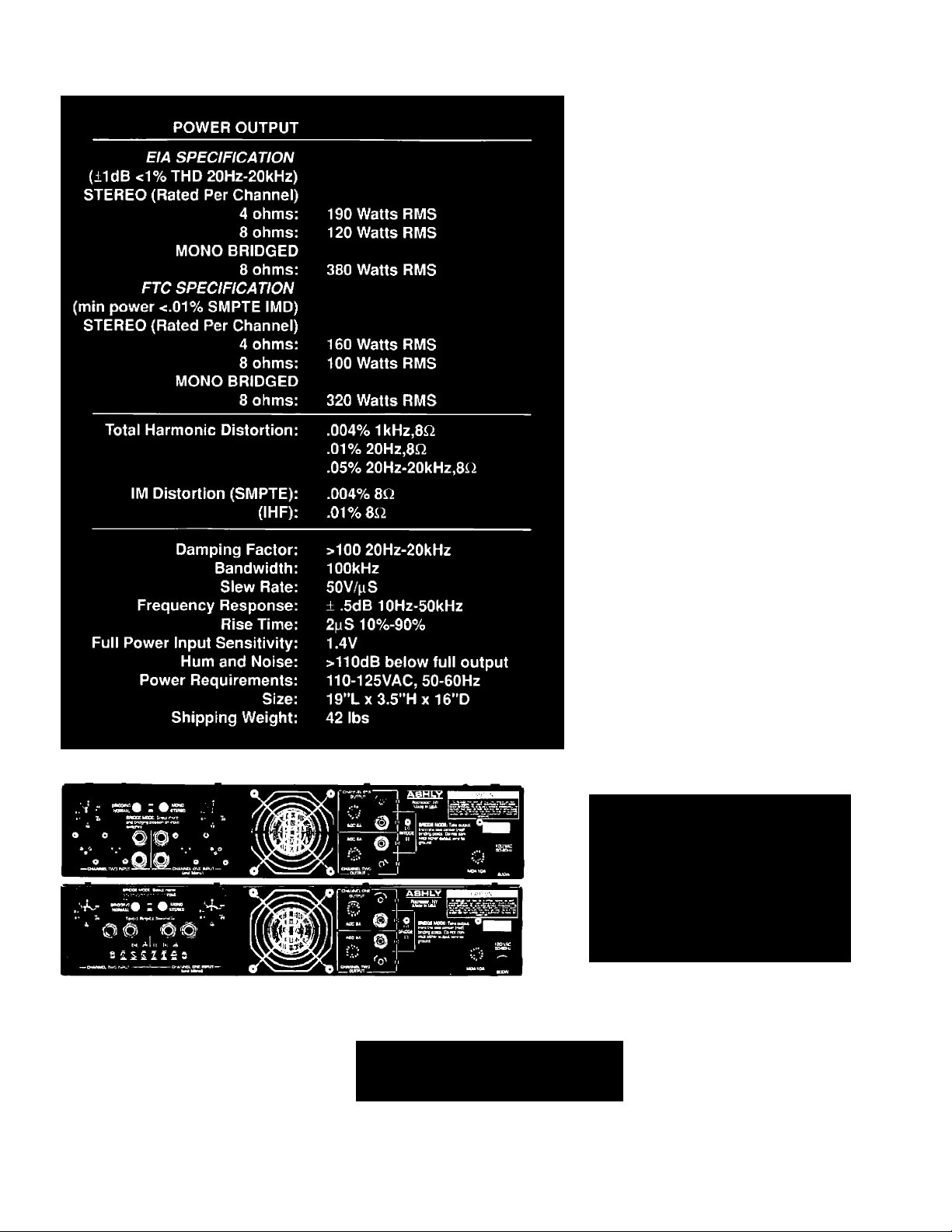
Specifications
Architect’s Specification
Ashly Model lOOOM
The power amplifier, being of two channels, shall deliver a
niinimiim power of 100 watts per channel Into 8 ohm loads
or 160 watts per channel Into 4 ohm loads with both chan
nels operating. When switched Into bridged mono mode. It
shall deliver at least 200 watts into a 16 ohm load or 320
watts Into an 8 ohm load. The aniplllicr shall be immune to
damage from shorted, open, or mismatched loads. Tlie
amplifier shall have a gain of 26dB ± ,5dB per channel and
an Input sensiUvily of 1.4 Volts ± 2% for full rated output.
Frequency response shall be lOHz to 20kHz ± .5dB. It shall
be stable Into any load Including pure capacitors and
indiietors. Hum and noise shall be at least llOdB below
full output and SMPTE intermodulation dislortion shall be
less Uian .01% at full output. The ampliller shall have rear
panel switching for mono and bridging modes and rear
mounted level controls. Tlie inputs shall be Ijalanced bridg
Ing type with male and female XLH type connectors as well
as 1/4 " phone Jacks. A three-color LED lype Indicator shall
be employed to show the power le\'el of each channel and
self contained forced air cooling shall be used. The power
outpiil devices shall be of the Lateral MOS-FET type. Tlie
aniplltler shall weigh 321b. net and mount in a standard 19
Inch rack using two spaces 13,5' high|. The power require
ment shall be 110-125VAC, 50-601 iz,
The power amplifier shall be an Ashly FEf- lOOOM.
Ashfy Model lOOOC
llic power amplifier, being of two channels, shall deliver a
minimum power of 100 watts per channel into 8 ohm loads
or 160 watts per channel Into 4 ohm loads with both chan
nels operating. When switched Into bridged mono mode. It
shall deliver at least 200 watts into a 16 ohm load or 320
walls Into an 8 ohm load. Tlie amplifier shall be immune to
damage from shorted, open, or mismatched loads. The
ampliner shall have a gain of 26dB ± .5dB per channel and
an Input sensitivity of 1.4 Volts ± 2% for full rated output.
Frequency response shall be lOHz to 20kllz ± .5dB. It shall
be stable Into any load including pure capacitors and
Inductors, Hum and noise shall he at least llOdB below
full ou [put and SMITE infermodiilatiou dislortion shall be
less than .01% at full output. The ampliller shall have rear
panel srvitchlng for mono and bridging modes and rear
mounted level controls. The inputs shall utilize 1 /4" phone
jacks as well as termlnal/barrier input strips. Self con
tained forced air cooling shall be used. The power oiilpul
devices shall be of the Lateral MOS-FET type. The amplifier
shall weigh 321b. net and mount in a standard 19 Incli rack
using two spaces (3.5" high]. The powci- requirement shall
be 110-125VAC. 50-60HZ.
The power amplifier shall be an Ashly FBT- lOOOC.
ASHLY
Since 1972
© 1990 Ashiv Audio
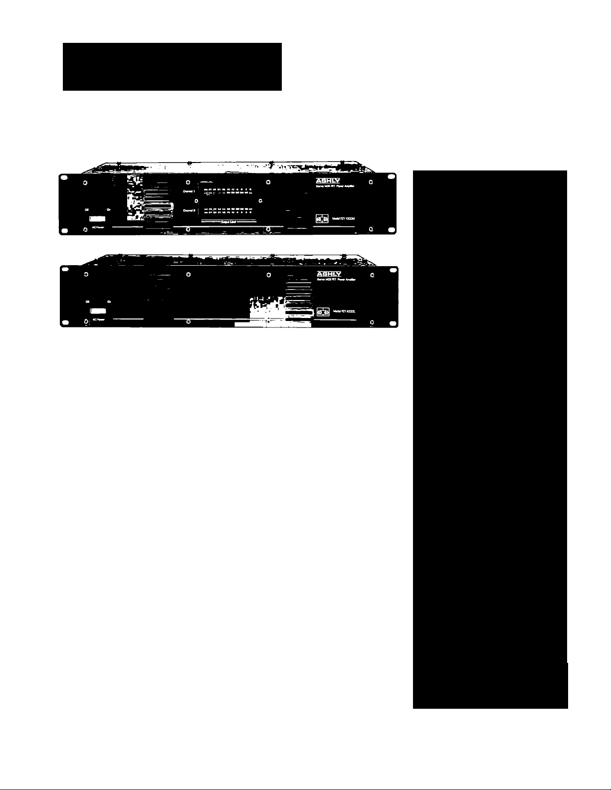
To provide maximum flexibility, Ashly offers two variations in our FET Power Amplifiers:
The FET-1000M (top) features XLR and 1/4" inputs.
The FET-1000C (bottom) utilizes Barrier Strips and 1/4” inputs.
 Loading...