

Page 1
18 Channel Digital Mixer
Operating Manual
ASHLY AUDIO INC.
847 Holt Road Webster, NY 14580-9103 Phone: (585) 872-0010
Toll-Free: (800) 828-6308 Fax: (585) 872-0739 ashly.com
All Trademarks referred to herein are the property of their respective owners
2018 Ashly Audio, Inc. • All rights reserved worldwide
Page 2

Operating Manual - digiMIX18 Digital Mixer
Important Safety Instructions
Consignes de sécurité à lire attentivement
The lightning ash with arrowhead symbol, within an equilateral triangle,
is intended to alert the user to the presence of uninsulated "dangerous
voltage" within the product's enclosure that may be of sufcient magnitude
to constitute a risk of electric shock to persons. The exclamation point
within an equilateral triangle is intended to alert the user to the presence
of important operating and maintenance instructions in the literature accompanying the device.
1. Read these instructions.
2. Keep these instructions.
3. Heed all warnings.
4. Follow all instructions.
5. To reduce the risk of re or electric shock, do not expose this
apparatus to rain or moisture.
6. Do not use this apparatus near water.
7. Clean only with dry cloth.
8. Do not block any ventilation openings. Install in accordance with
the manufacturer’s instructions.
9. Do not install near any heat sources such as radiators, heat
registers, stoves, or other apparatus.
10. Do not defeat the safety purpose of the polarized or groundingtype plug. A polarized plug has two blades with one wider than the
other. A grounding type plug has two blades and a third grounding prong. The wide blade or the third prong are provided for your
safety. If the provided plug does not t into your outlet, consult an
electrician for replacement of the obsolete outlet.
11. Protect the power cord from being walked on or pinched par-
ticularly at plugs, convenience receptacles, and the point where they
exit from the apparatus.
12. Only use attachments/accessories specied by the manufac-
turer.
13. Use only with the cart, stand, tripod, bracket, or table specied
by the manufacturer, or sold with the apparatus. When a cart is
used, use caution when moving the cart/apparatus combination to
avoid injury from tip-over.
14. Unplug this apparatus during lightning storms or when unused
for long periods of time.
15. Refer all servicing to qualied service personnel. Servicing is
required when the apparatus has been damaged in any way, such as
power-supply cord or plug is damaged, liquid has been spilled or objects have fallen into the apparatus, the apparatus has been exposed
to rain or moisture, does not operate normally, or has been dropped.
Le symbole de la èche dans un triangle équilateral symbolisant la foudre
est prévu pour sensibiliser l’utilisateur à la présence de tension de voltage
non isolée à l’intérieur de l’appareil. Elle pourrait constituer un danger de
risque de décharge électrique pour les utilisateurs. Le point d’exclamation
dans le triangle équilatérale alerte l’utilisateur de la présence de consignes
qu’il doit d’abord consulter avant d’utiliser l’appareil.
1. Lisez ces instructions.
2. Conservez ces instructions.
3. Observez les avertissements.
4. Suivez ces instructions.
5. Pour réduire le risque de feu ou la décharge électrique, ne pas
exposer cet appareil pour pleuvoir ou l'humidité.
6. Ne pas utiliser l’appareil près de l’eau.
7. Le nettoyer à l’aide d’un tissus sec.
8. Ne pas bloquer les ouvertures de ventilation, installer selon les
consignes du fabricant.
9. Eloigner des sources de chaleur tel: radiateurs, fourneaux ou
autres appareils qui produisent de la chaleur.
10. Ne pas modier ou amputer le système de la mise à terre. Une
prise avec mise à terre comprend deux lames dont une plus large
ainsi qu’une mise à terre: ne pas la couper ou la modier. Si la prise
murale n’accepte pas la che, consulter un électricien pour qu’il
remplace la prise désuète.
11. Protéger le cordon de secteur contre tous bris ou pincement qui
pourraient l’endommager, soit à la che murale ou à l’appareil.
12. N’employer que les accessoires recommandés par le fabricant.
13. N’utiliser qu’avec les systèmes de xation,chariots, trépied ou
autres, approuvés par le fabricant ou vendus avec l’appareil.
14. Débrancher l’appareil lors des orages électriques ou si inutilisé
pendant une longue période de temps.
15. Un entretient effectué par un centre de service accrédité est
exigé si l’appareil a été endommagé de quelque façon: si il a été
exposé à la pluie,, l’humidité ou s’il ne fonctionne pas normalement
ou qu’il a été échappé.
2
Page 3

Operating Manual - digiMIX18 Digital Mixer
Table of Contents
1 Introduction and Important digiMIX tips. . . . . . . . . . . . . . . . . . . 4
2 Mixer Controls . . . . . . . . . . . . . . . . . . . . . . . . . . . . . . . . . . . . . . . 6
3 Rear Panel Features . . . . . . . . . . . . . . . . . . . . . . . . . . . . . . . . . . 12
4 Getting Started. . . . . . . . . . . . . . . . . . . . . . . . . . . . . . . . . . . . . . 14
5 System Functions . . . . . . . . . . . . . . . . . . . . . . . . . . . . . . . . . . . . 20
6 Other Mixer Functions (Firmware Update, Preset Backup/Restore,
Factory Reset, EZ-Mode, Automixer, Crossfade) . . . . . . . . . . . . . . . . . . 22
7 Digital Audio Options (Dante-3018, USB-3018). . . . . . . . . . . . . 25
8 Rack Ear Installation . . . . . . . . . . . . . . . . . . . . . . . . . . . . . . . . . 27
9 iPad Remote Control. . . . . . . . . . . . . . . . . . . . . . . . . . . . . . . . . . 28
10 Troubleshooting . . . . . . . . . . . . . . . . . . . . . . . . . . . . . . . . . . . . 29
11 Specications . . . . . . . . . . . . . . . . . . . . . . . . . . . . . . . . . . . . . . 30
12 Dimensions. . . . . . . . . . . . . . . . . . . . . . . . . . . . . . . . . . . . . . . . 32
13 Block Diagram . . . . . . . . . . . . . . . . . . . . . . . . . . . . . . . . . . . . . 33
14 Warranty . . . . . . . . . . . . . . . . . . . . . . . . . . . . . . . . . . . . . . . . . 34
Unpacking
As a part of our system of quality control, every Ashly product is carefully inspected before leaving the factory to ensure awless appearance.
After unpacking, please inspect for any physical damage. Save the shipping carton and all packing materials, as they were carefully designed
to reduce to a minimum the possibility of transportation damage should the unit again require packing and shipping. In the event that damage
has occurred, immediately notify your dealer so that a written claim to cover the damages can be initiated.
The right to any claim against a public carrier can be forfeited if the carrier is not notied promptly and if the shipping carton and packing
materials are not available for inspection by the carrier. Save all packing materials until the claim has been settled.
About Ashly
Ashly Audio was founded in 1974 by a group of recording engineers, concert sound professionals, and electronics designers. The rst products were
elaborate custom consoles for friends and associates, but business quickly spread to new clients and the business grew. The philosophy we established
from the very beginning holds true today: to offer only the highest quality audio tools at an affordable cost to the professional user – ensuring reli-
ability and long life. Many years later, Ashly remains committed to these principles.
Ashly’s exclusive Five Year, Worry- Free Warranty (three years on touchscreen and motorized faders) remains one of the most generous policies
available on any commercial- grade product. The warranty covers every product with the Ashly brand name and is offered at no extra cost.
Please read this entire manual to fully understand the features and capabilities of this product.
FCC Compliance
This device complies with part 15 of the FCC Rules. Operation is subject to the following two conditions:
1. This device may not cause harmful interference
2. This device must accept any interference received, including interference that may cause undesired operation
Note: This equipment has been tested and found to comply with the limits for a Class B digital device, pursuant to part 15 of the FCC Rules. These limits are designed
to provide reasonable protection against harmful interference in both a commercial and residential installation. This equipment generates, uses and can radiate
radio frequency energy and, if not installed and used in accordance with the instructions, may cause harmful interference to radio communications. However,
there is no guarantee that interference will not occur in a particular installation. If this equipment does cause harmful interference to radio or television reception,
which can be determined by turning the equipment off and on, the user is encouraged to try to correct the interference by one or more of the following measures:
- Reorient or relocate the receiving antenna.
- Increase the separation between the equipment and receiver.
- Connect the equipment into an outlet on a circuit different from that to which the receiver is connected.
- Consult the dealer or an experienced radio/TV technician for help..
3
Page 4

Operating Manual - digiMIX18 Digital Mixer
1 INTRODUCTION
Thank you for purchasing the Ashly digiMIX18 digital and networkable 18 input x 12 bus mixer.
With 16 high performance discrete mic/line preampliers, assignable auto-mixer, two line-level inputs, assignable cross-fade mode,
DSP processing with parametric and graphic EQ, compressor/limiter, expander/gate, delay, invert polarity, two built in stereo ef-
fects buses, eight aux buses, six DCA groups, sensitive LED metering, preset control, password security, iPad® remote control via
network connection, and much more, the compact and powerful digiMIX18 offers all the right tools to manage your sound job
with condence. The digiMIX18 also comes with racks-ears that allow the mixer to be installed in a standard 19" equipment rack.
In order to thoroughly understand the features of the digiMIX18, please read this entire manual as you explore the controls,
touchscreen, and remote control capabilities of your mixer.
Standard Features
• 16 low noise mic/line preamps with Neutrik Combo jacks, dedicated trim controls, +48V phantom power, phase invert
• Rack ears included for mounting to standard 19" equipment rack
• Automixer (gain sharing), individually assignable to input channels 1-16
• Stereo line-level input on 1/4" jacks
• Cross-fade mode for panning between any two assigned channels
• TRS inserts on channels 1-8
• 8 aux sends, assignable pre/post
• 6 DCA for fader or mute groups
• 2 stereo effects buses (FX) with fully editable reverbs, delay with tap tempo, tremolo, anger, and chorus.
• 7 inch color LCD touch screen for graphical viewing, assign, and setup
• Wired network interface for iPad remote control using Ashly digiMIX18 app, available free on the App Store
• EZ-Mode for secure, simplied touchscreen or iPad® control
• 100mm precision Alps® motorized fader
• Pan control
• High resolution delay (0.2mS) on every main L/R output, input1-18, aux1-8, or FX1-2
• Expander/noise gate on every input and FX channel
• Compressor/limiter on every input, output, and FX channel
• 4-band parametric/shelving EQ lters plus HPF/LPF on every input, output, and FX channel
• 31-band graphic EQ on main L/R and aux1-8 outputs
• Stereo link available on inputs 1-16 and aux1-8 outputs
• Solo/PFL on every input, main L/R output, aux1-8, or FX1-2
• Stereo main L/R output on XLR and 1/4" phone jacks with dedicated level control
• Headphone and control room outputs with level control
• User presets for Scene Settings, DSP channel settings, FX settings, or GEQ settings, plus channel copy function
• 24-bit A/D and D/A converters, 32-bit DSP processing, 48KHz sampling rate
• Password security
• Utility programs for Windows® and Mac® for preset backup/restore and rmware update
• Internal 100-240VAC universal power supply
• Safety/compliance: cTUVus, CE, FCC, RoHs
®
Optional Features
• Dante-3018 network audio interface, eld installable
• USB-3018 multi-track audio interface, eld installable
4
Page 5

Operating Manual - digiMIX18 Digital Mixer
10 Tips Before Getting Started:
► Channel Selection - Each input, output, and FX channel has its own select button for quick access.
Changing the fader or other settings affects the currently selected channel.
► Channel Assignment - Input channels must be assigned or sent to main L/R, aux1-8, or FX1-2 mixes
using the assign or send buttons. Channel assignments are stored in the working preset, and also saved
in a scene preset. (sec. 2.31)
► Working Preset - The mixer remembers all settings in whatever state they are in when the mixer is
powered off. When powered back on, the mixer loads these settings as the working preset.
► Saved Presets -
settings), DSP Channel (single channel), FX (effect), and GEQ (graphic EQ - outputs only) (sec. 2.31).
There are four types of presets that can be saved on the mixer: Scene (all mixer
All
presets can be backed up and restored between the mixer and a computer using the digiMIX18 Preset Utility
software.
►
Ethernet/USB Control Jacks (rear panel) -
(sec. 6.2)
Use these jacks with the utility programs to update mixer
firmware or backup/restore presets with a computer. Ashly recommends using only the USB connection
for firmware update. digiMIX18 Firmware Utility and digiMIX18 Preset Utility programs are available
for both Windows and MAC. (sec. 6.1 and 6.2)
For wireless remote control of the mixer, connect the Ethernet jack to a network with Wi-Fi and use an
iPad running the Ashly digiMIX app, available free on the App Store. (sec. 9)
► EZ-Mode - EZ-Mode offers a simplified touchscreen control surface on the mixer or iPad app for a
non-technical user to operate the mixer with limited access to mixer functions. (sec. 6.4)
► Password Protection - Access password and security settings by pressing the System button.
Passwords are always four character, alpha-numeric, and case sensitive. The password entered on the
mixer will always be the same one used by the Ashly digiMIX18 app on a connected iPad. (sec. 5.4)
With a password, the entire mixer can be fully locked or unlocked. In EZ-Mode, password protection can limit
operation of the mixer to EZ-mode only. Also within EZ mode, faders and icons can be locked independently.
► iPad Connection -
The mixer does not provide its own Wi-Fi signal, an Ethernet connection to a network
with Wi-Fi is required. Only one iPad at a time can connect to digiMIX18. If more than one digiMIX18 is
discovered, a drop-down list of all available mixer IP addresses is displayed on start-up. The iPad app and
mixer touchscreen will both display a solid green box in the upper left corner when successfully connected.
► Using the Touchscreen - There are two different top-level mixer touchscreen modes, Mixer mode
and Long Fader mode. A button on the mixer (or iPad app) toggles between the two modes. Mixer Mode
shows all inputs and outputs, also showing a long fader for main L/R output on the right and another
long fader on the left for the currently selected channel. Alternately in Long Faders mode, groups of
eight channels are displayed, all with long faders.
In either mode, press the unlabeled "PEQ" box in the touchscreen's upper left corner to edit the selected
channel parameters or system functions. (sec. 2.32) This box always displays the selected channel's PEQ curve.
► Naming Channels - Edit channel names by first selecting a channel, then press the Fader Name
button found below the touchscreen.
5
Page 6
Operating Manual - digiMIX18 Digital Mixer
2 MIXER CONTROLS
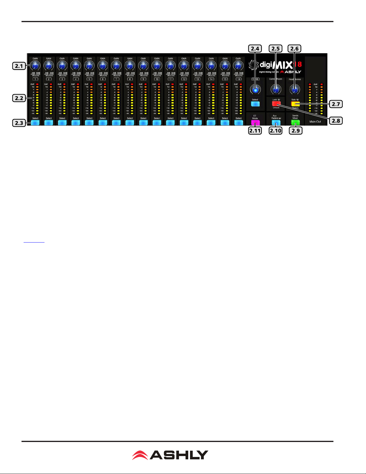
2.1 Input Trim
This controls the gain of the analog mic or line input preamplier. For analog inputs, this is the most important control for setting up proper gain structure in the mixer. Properly set, it helps to avoid clipping and maintains low noise. A good rule is that
with typical input signal present on a channel, adjust the trim control to allow 20dB headroom between the expected signal's
peak level and when it clips. In other words, normal signal peaks should be around "0" on the meter. Set this control rst and
then leave it alone unless the input source changes. Do not use the trim control to adjust mix volume later on, use the channel's
fader control instead.
2.2 Input/Output LEDs
Input LEDs indicate the signal level of each input in dBu, after the preamplier stage but pre-fader. Output LEDs indicate signal
level at the output. They can alternately indicate every channel's current fader position by pressing the Faders/Meters button
(sec. 2.23).
2.3 Select Button
Every input, main L/R output, aux1-8, and FX1-2 have a dedicated select button. All routing assignment, DSP, sends functions,
and motorized fader activity are applied only to the selected channel. This allows the user to quickly change from one channel
to the next from any mixer function.
2.4 Ch17-18 Stereo Line Input
This level control and select button always control ch17-18 stereo line level inputs. Ch17-18 are always stereo linked and
be assigned or sent to main L/R, aux1-8, and FX1-2
. Using the left (mono) input sends signal to both channels.
can
2.5 Control Room Level Control
This adjusts the level of the control room outputs. Control room outputs always use the post-fader signal from the main L/R outputs.
2.6 Headphones Level Control
Plug headphones in the front or back of the mixer for monitoring the main L/R outputs or the selected solo channels. Use the
Headphones Level control to adjust volume.
2.7 Solo/Meters Button
Press this button to toggle the main L/R output LED bars between indicating main L/R signal level, or stereo solo level.
2.8 Lock/Unlock Button
Press this button to lock/unlock the mixer with a password. Passwords are up to four characters and are case sensitive. (sec 5.4)
6
Page 7
Operating Manual - digiMIX18 Digital Mixer
2.9 Sends Mixer
Press this button to open the sends mixer overview screen, where the mixer's main L/R, aux1-8, and FX1-2 channel assignments
or send levels can be quickly viewed and changed.
2.10 Aux Faders
Press this button when any aux1-8 output is selected to view current aux1-8 fader position. The aux1-8 fader position will be
displayed on the ch1-8 input LED bars. The main L/R fader position will also be displayed on the main L/R out LED bars.
2.11 EZ Mode
Press this button to enter the mixer's EZ-Mode.
to adjust basic mixer functions with ease, locking out most other mixer controls. See sec 6.4 for details.
EZ-Mode provides a simple and secure user interface for a non-technical person
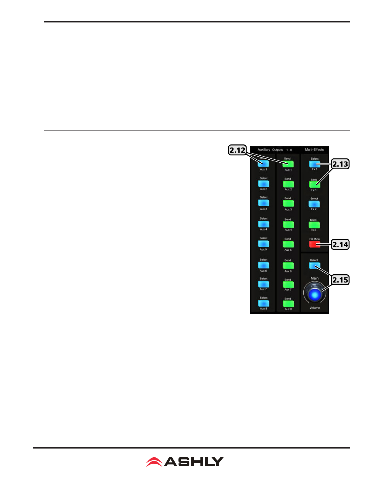
2.12 Aux1-8 Select and Send Buttons
Aux outputs are typically used for secondary mixes such as monitors, video
feed, assistive listening devices, subwoofers, etc. Aux outputs can be stereo
linked as 1-2, 3-4, 5-6, or 7-8.
Press an aux1-8 select button to give that aux output the focus in the mixer.
Press an aux1-8 send button to quickly view and adjust the level of all channels currently available for sending to that aux output.
Adjust any channel's level to aux1-8 by rst tapping the desired channel in
an aux1-8 sends screen to select it, then use the parameter adjust fader on
the touchscreen or adjust parameter knob on the mixer to set the level sent
to that aux.
Channel sends to aux1-8 can be selected as pre or post-fader, the default is
pre-fader.
2.13 FX1-2 Select and Send Button
This mixer has built in stereo effects including reverbs, delay, chorus, anger,
tremolo, and several combinations. Press the FX Editor button below the
touchscreen to create and save up to 104 different custom effects, or use the
defaults. Only two effects can be used on the mixer at a time. See section 4.8
for more details on effects.
Press the FX1 or FX2 select button
Press
the FX1 or FX2
channels currently available for sending to that FX.
Adjust any channel's level to the FX by rst tapping the desired channel from within the FX sends window, then use the parameter
adjust fader on the touchscreen or adjust parameter knob on the mixer to adjust the level sent to that FX.
Channel sends to FX1-2 can be selected as pre or post-fader, the default is post-fader.
Each FX bus must additionally be routed to the main L/R or aux1-8 outputs as desired. To assign an FX to the main L/R output,
select the FX, then press the assign button, then tap the <Main> button on the touchscreen so that it turns blue. To send an FX to an
aux1-8 output from the assign window, tap any aux1-8 level control, then use the parameter adjust control to set the aux send level.
send button to quickly view and adjust the level of all
to give that FX the focus in the mixer.
2.14 FX Mute
Press this button to mute FX1 and FX2. This is useful for comparing sound with and without effects.
2.15 Main Select and Volume Control
Press the <Main> select button
to the main L/R outputs. When main L/R is selected, the volume control works together with the motorized fader and touchscreen.
to give the main L/R outputs the focus in the mixer. This level control always adjusts the signal level
7
Page 8
Operating Manual - digiMIX18 Digital Mixer
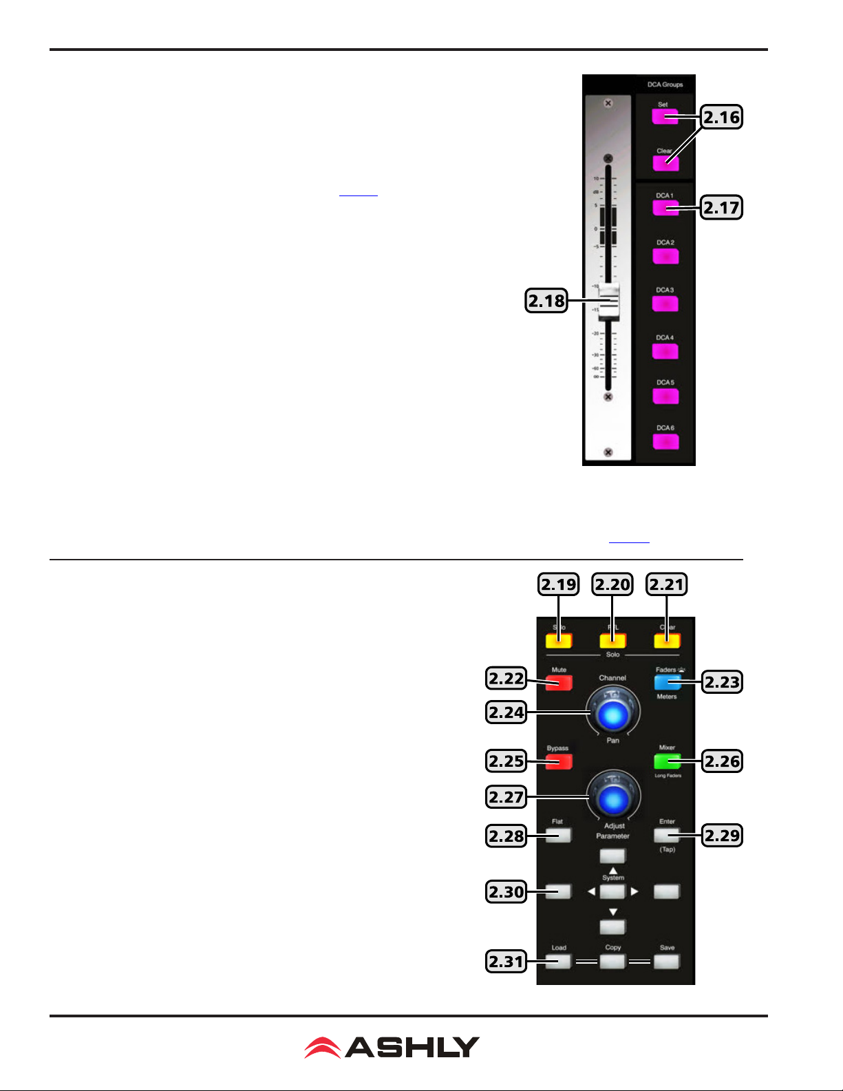
2.16 DCA Set and Clear Button
Digital controlled ampliers (DCA1-6) are used to combine multiple inputs, aux, or
FX outputs into one mix group for unied control of that group. DCA groups allow
the relative fader position of each member to be preserved while adjusting their
overall combined level as a group. It also allows the group to be instantly muted. This
is typically used for grouping vocals, drums, choir or orchestral sections, etc. DCA
groups must rst be dened before using EZ-Mode (sec 6.4).
To dene a DCA group, rst press the DCA Set button so that it ashes, then select
one of the six DCA buttons on the mixer or touchscreen, then tap individual channels
on the mixer screen to select them for that DCA group. Selected channels turn purple
on the screen. When nished, press the DCA Set button once again to save settings.
Whenever a DCA button is then selected and lit, the fader will control all channels
assigned to that DCA. Channels can be assigned to more than one DCA groups.
To clear a DCA group, rst select the DCA, then press the DCA set button so it ashes,
then press the DCA clear button, conrm the action by tapping "Yes" on the touchscreen
prompt, then nally press DCA set once more.
2.17 DCA1-6 Buttons
These six buttons are used to select a pre-dened DCA group for fader, mute, or solo
control. If the DCA group is not yet dened, a touchscreen message prompts for a
response before proceeding further.
2.18 Motorized Fader
This is the primary level control for all inputs, main L/R and aux1-8 outputs, effects master, and DCA control. Press the <Select>
button on any input, output, or DCA, and the motorized fader will control its level. The fader works together with other level
controls used for the same selected signal. Motorized fader speed can be adjusted in the system screen (sec. 5.2).
2.19 Solo Button
Use the solo button for listening to one or more isolated signals in the headphones.
Select an input, output, FX, or DCA group, then press the solo button to include
that signal in the solo bus. The default solo setting is post-fader, meaning the
solo signal level depends on the solo channel's fader position.
Press the solo clear button to clear all selected solo channels. With no channels
selected for solo, the headphone output defaults to the main L/R output, post
fader. Solo status can also be viewed and set from the touchscreen display.
The solo feature is in stereo, so that any stereo linked channels or FX are heard
in stereo.
2.20 PFL Button
PFL is used to monitor selected solo channels at their pre-fader level, meaning
the selected solo channel(s) will still be heard even if its fader is turned down.
2.21 Clear Button
Press this button to clear all solo selections and return the headphone output
to main L/R.
2.22 Mute Button
The mute button is used to silence the selected input, output, aux, FX, or DCA
group. Mute status can also be seen or controlled using the touchscreen display.
8
Page 9

Operating Manual - digiMIX18 Digital Mixer
2.23 LED Faders/Meters Select Button
This button is used to toggle the input LED bars (sec. 2.2) to either indicate the current signal levels of all channels, or show the
current fader position of all channels. The button is lit when showing the current fader positions.
2.24 Pan Control
The pan control is dedicated to fading signals from left to right in the main L/R mix. It is also used for Crossfade mode (sec. 6.6)
to quickly fade between any two assigned channels. Its stereo position for the selected channel is displayed on the touchscreen.
2.25 Bypass Button
Press the bypass button from within the PEQ, GEQ, Exp/Gate, or Comp/Lim DSP function to disable that function for the currently
selected channel. This is useful for comparing signal with and without individual DSP processing elements. Pressing the bypass
button from the Channel screen turns only the PEQ function on and off.
2.26 Mixer/Long Faders Select Button
This button toggles between the two mixer displays, one showing every mixer input and output (mixer mode), the other showing
groups of eight channels with longer faders (long fader mode). Channel names are shown in long fader mode. To edit a channel
name, press the fader name button below the touchscreen, then use the pop-up touchscreen keyboard to enter a name.
If Crossfade mode is active (sec. 6.6), pressing this button will toggle through both mixer display modes, as well as Crossfade mode.
2.27 Adjust Parameter Control
This control is typically used to adjust the currently active or highlighted DSP parameter within the touchscreen display. It may
also work together with other controls depending on the currently active function.
2.28 Flat Button
Press this button to atten the PEQ, GEQ, Exp/Gate, or Comp/Lim settings on the currently selected channel.
2.29 Enter (Tap) Button
This button has two functions. The rst is to offer a "Yes" response any time the touchscreen prompts for yes or no answer. For
example, after pressing the at button when the touchscreen asks "Reset EQ curve to at?", you can tap "Yes" on the touchscreen
or press the Enter button.
The second function is to manually set an FX delay time to match the beat of the music, also referred to as "tap delay". Press the FX1
or FX2 button and select Delay as the effect type. Set the delay time by pressing the TAP button at the start and end of the desired
delay time. Maximum tap delay is 1200ms.
2.30 System Buttons
The system button opens the touchscreen display to a variety of utility controls including EZ-mode (sec. 6.4), cross-fade mode (sec.
6.6), automix channel assign (sec. 6.5), LCD brightness, fader speed calibration, password/security functions, restore default settings,
and more. The up/down/left/right buttons are used to select and adjust controls shown on the touchscreen, their purpose depends on
the currently active function. For example, with the GEQ function active, the two Left/Right system buttons move to select one of
the 31 EQ bands, while the Up/Down buttons adjust the selected EQ lter level. The buttons work together with touch controls on the
screen, but for smaller touchscreen controls it may be easier to use the system buttons.
2.31 Load, Copy, Save Buttons
There are four different types of user presets that can be saved/loaded on the digiMIX18.
1)
2) DSP Channel - The DSP channel preset is used on input, output, and aux channels. It saves/loads a single channel's
assignments, channel settings, gate, comp, and PEQ/GEQ settings. Up to 48 different DSP channel presets can be saved.
3) FX - FX presets are used to save/load up to 104 different user dened FX1 and FX2 effects.
4) GEQ - The 48 GEQ presets are used to save/load graphic equalizer settings, which are only used on outputs.
Scene - Scene presets are the most inclusive, capturing all audio settings in the mixer. Up to 24 scene presets are available.
9
Page 10
Operating Manual - digiMIX18 Digital Mixer
SAVE: To save a mixer preset, rst press the save button, then use the touchscreen to select one of the four preset types. Next, select
a preset number to use, then press the preset name box, type in a preset name, press enter, then press Save on the touchscreen to
write to memory. Use UpPage and DownPage to navigate to the next available group of presets.
LOAD: To load a mixer preset, press the load button, then in the touchscreen window select the type of preset to load, then select
one of the available presets and press the touchscreen load button.
To delete a mixer preset, press the load button, select a preset to delete, then press the touchscreen delete button.
COPY: To copy current settings from one channel to another, press the Copy button on the mixer or the Copy Channel button
from the touchscreen system page. The resulting touchscreen window will display all inputs and outputs, the currently selected
channel will be ashing. This is the channel that will be copied from, and can be changed by selecting any other channel using the
touchscreen or control surface select buttons.
Next, press the <Copy to: Select> button on the touchscreen and select the channel(s) you want settings to be copied to. Next, press
the touchscreen <Copy> button to complete the copying process.
►
TIP: All channel DSP functions are individually listed across the bottom of the touchscreen. Each function can be checked or
unchecked to include or exclude from being copied. Only the checked parameters will be copied.
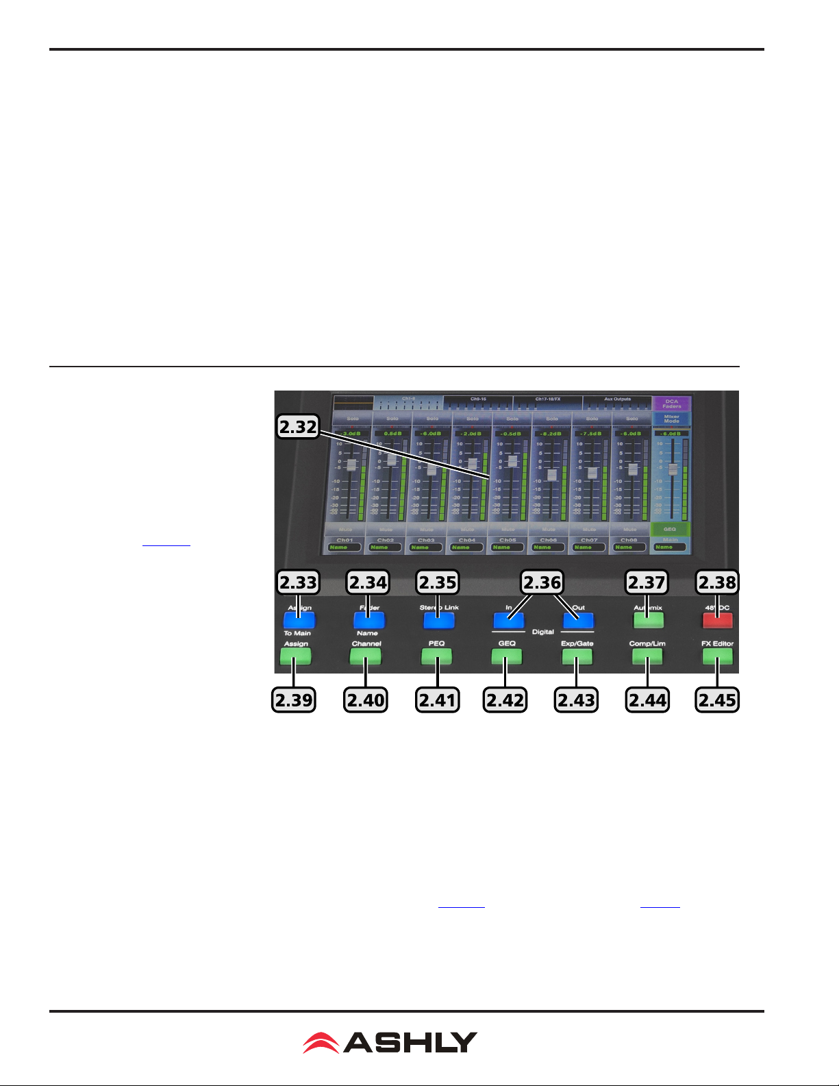
2.32 The Touchscreen Display
Most mixer functions can be adjusted
using either the touchscreen or the
buttons/knobs. Some functions can only
be adjusted using the touchscreen.
Level and fader controls are adjusted
by either dragging the control, or by
rst selecting it then turning the adjust
parameter knob (sec. 2.27).
In Mixer Mode, touch any channel fader
to select it. The currently selected input
channel, FX, or aux1-8 fader will appear
along the left side. Parameters include
channel name and number, fader level,
plus mute, solo, and auto-mixer status. In
mixer mode, the main L/R output fader is
always shown along the right side.
►
TIP: The unlabeled touch-box above
the solo function shows the current PEQ
curve for the selected channel. Touch
this box to access all DSP functions for the selected channel.
►
TIP: Above the PEQ box is a smaller unlabeled box which turns bright green when the mixer is connected to the iPad app or
digiMIX utility app on a computer. It turns black when the connection is lost.
►
TIP: The channel name can be edited by pressing and holding the "Name" text box below any long fader until a keyboard appears
on screen. Type in the new name and press enter to complete. To escape out of the keyboard without changing anything, press the
keyboard icon in the lower right corner.
2.33 Assign to Main
This button is used to assign the currently selected input channel or FX1-2 to the main L/R mix, and becomes lit when assigned. Assignment status can also be edited using the touchscreen Assign window (sec. 2.39), or the Sends Mixer button (sec. 2.9).
2.34 Fader Name
Press this button to name the currently selected input or output channel using the pop-up touchscreen QWERTY keyboard.
10
Page 11

Operating Manual - digiMIX18 Digital Mixer
2.35 Stereo Link
The stereo link button is used to link two adjacent input channels or aux outputs together so that all level, DSP, and assignment
parameters are equally applied to both channels. Channel pairs can only be linked where the odd numbered channel is rst,
i.e. 1-2, 3-4, aux1-2, aux3-4, etc. When stereo linking a pair of channels, the mixer automatically routes the odd numbered
channel to the left output and the even numbered channel to the right output and they will be heard in stereo. To see the various ways that stereo linking and panning operate when routed to main L/R or when using linked aux outputs, see section 4.7.
2.36 Digital In/Out
The optional Dante-3018 or USB-3018 digital audio module must be installed before using this feature. These buttons open the
digital audio assignment screen to enable mixer channels for digital audio use. See section 7 for complete details.
2.37 Automix
Press this button to individually assign inputs 1-16 for automix, and to enable the automixer. See section for complete details.
2.38 48VDC Phantom Power
Press the 48VDC button to assign +48V phantom power to any of input channels 1-16.
2.39 Assign
Press the assign button to view or change where the currently selected input or FX is routed to in the mixer. The selected channel
is always shown on the left side of the assign window. Inputs can be assigned or sent to main L/R, aux1-8, and FX1-2.
Assigned outputs appear blue when selected. Signal level sent to aux1-8 and FX1-2 buses must be adjusted individually using
the touchscreen parameter adjust fader on the right side of the display, or by using the adjust parameter knob (sec. 2.27). There
are also several quick links to other mixer functions from the assign window.
2.40 Channel
Press the channel button to view and access all DSP settings for the currently selected input, main L/R, FX1-2, or aux1-8 output.
The currently selected channel (or linked channels) is always shown on the left side of the touchscreen display.
Every DSP function has a dedicated On/Off button on the touchscreen.
Input channel DSP functions include stereo pan, polarity invert, channel delay up to 300ms, stereo link, expander/gate, PEQ,
and compressor/limiter. Main L/R and aux1-8 outputs do not have expander/gate function.
or loaded as a DSP channel preset (sec. 2.31).
Channel DSP settings can be saved
2.41 PEQ
Press the PEQ button to engage the 6-band EQ for the currently selected input, main L/R, FX1-2, or aux1-8 output.
The PEQ has four parametric lters with adjustable frequency, bandwidth (Q), and gain. Any of these four can also be set as
shelving lters by pressing their <Type> icon on the touchscreen. Two additional lters complete the PEQ section, a tuneable
hi-pass (HPF) and low-pass (LPF), each offering 20 different slope types. For tips on using the PEQ see section 4.2.
Press the Bypass button (sec. 2.25), or the touchscreen ON button to compare signal with and without PEQ.
button (sec. 2.28) or the touchscreen Flat EQ button to return all PEQ lters to their 0dB gain and default starting parameters
Press the Flat
2.42 GEQ
The GEQ 31-band graphic equalizer is only available on the main L/R and aux1-8 outputs. It is not available on inputs or FX1-2.
Select and drag individual lter faders up/down on the touchscreen, or use the left-right buttons on the touchscreen, or use the
system left/right buttons on the mixer front panel (sec. 2.30) to select frequency, then use the system up/down buttons to adjust
lter level. Up to 48 different GEQ presets can be saved to memory and loaded later for use with specic rooms or loudspeakers.
Press the Bypass button (sec. 2.25), or the touchscreen ON button to compare signal with and without GEQ. Press the at
button (sec. 2.28) or the touchscreen at EQ button to return all GEQ lters to 0dB.
2.43 Exp/Gate
Press this button to engage the noise gate/expander for the selected channel. This function will silence or reduce the level
of an input or FX signal when it falls below a user dened threshold. Controls include on/off, threshold, attack time, release
time, and ratio. Innite ratio silences all signal below the threshold (noise gate), while using a lower ratio allows some
signal below the threshold to pass (downward expansion). Press the at button to return the expander/gate parameters to
their default settings. See section 4.4 for tips on using an expander/gate.
11
Page 12

Operating Manual - digiMIX18 Digital Mixer
2.44 Comp/Lim
Press the Comp/Lim button to engage the compressor/limiter function on a selected input, main L/R, FX1-2, or aux1-8 output. Use
this feature to reduce the dynamic range of a signal (compressor) or to limit how loud a signal can go (limiter). Touchscreen controls include on/off, threshold, attack time, release time, ratio, and post gain. See section 4.5 for tips on using a compressor/limiter.
2.45 FX Editor
Two digital effect buses are available. Customized effects can be created, saved, and assigned, and include three types of reverb, delay,
tremolo, anger, chorus, or combinations (sec. 4.8). Up to 104 different user dened effects can be saved to the mixer (sec. 2.31).
3 REAR PANEL FEATURES
3.1 Combo Jack Inputs, Channel 1-16
There are 16 mic/line channels that use a XLR-1/4 phone
jack" combo connector. The female XLR connector is for a
balanced mic input, and the TRS (tip-ring-sleeve) phone jack
is for balanced line level input. See the illustration for proper
balanced or unbalanced wiring of XLR and phone jacks. The
mic preamp circuit is overridden when the phone jack is
inserted. Avoid plugging or unplugging connectors when the
volume is turned up, as loud transient pops can result which
may damage loudspeakers.
3.2 TRS Insert, Channel 1-8
Channels 1-8 are each equipped with a single TRS jack
insert point for use with external processors. Tip=send, and
ring=return. The outgoing signal is taken right after the analog trim control, and the return signal goes directly to a D/A
converter for routing to the digital bus for DSP processing.
3.1 - Balanced and Unbalanced connector wiring
3.3 Channel 17-18 Stereo Line Inputs
These inputs function as a stereo line level input (sec. 2.4) . There is no adjustable preamp on these inputs, so a strong input signal
level (0dBu) is recommended. Plugging in only the left input (channel 17) sends a mono signal to both left and right inputs.
3.4 Main L/R XLR Outputs*
The left and right main outputs on balanced XLR male connectors are controlled by the <Main> volume control (sec. 2.15). They
are wired in parallel with the main L/R phone jack outputs.
3.5 Main L/R Phone Jack Outputs*
The main L/R outputs on TRS phone jack connectors are wired in parallel with the main L/R XLR outputs.
12
Page 13

Operating Manual - digiMIX18 Digital Mixer
3.6 Aux1-8 Outputs*
These eight phone jacks are pseudo-balanced outputs for aux1-8 (sec. 2.12). They have single-ended signal with balanced impedance.
* If plugging a digiMIX18 output into a powered speaker or other mixer input, phantom power must be turned off on that input.
3.7 Control Room Output
The balanced stereo control room outputs use the same signal as the main L/R outputs, but with a separate volume control.
3.8 Headphone Jack
There is a stereo headphone jack on the front and back of the mixer, controlled by the headphones level control.
3.9 AC Inlet
This is used to connect the mixer to AC mains using the detachable AC cord provided with the unit.
3.10 Power Switch
This switch turns on power to the mixer. Turn-on time is about 15 seconds.
3.11 Ethernet Control Jack
The Ethernet jack is used for connecting the mixer to a network for remote iPad control (sec. 9), or for using the "digiMIX18
Preset Utility" software (sec. 6.2). Ashly recommends using the USB control jack for the rmware update software.
3.12 USB Control Jack
The USB Control jack (recommended for rmware update) is an alternative to the Ethernet jack for "digiMIX18 Firmware Utility"
and "digiMIX18 Preset Utility" software. A specic USB device driver may need to be installed on your computer rst (sec. 6.1).
3.13 Digital Audio Module Option
Ashly offers optional eld installable Dante-3018 or multi-track USB-3018 audio modules for the
the module, rst remove the mixer from power, then remove the two screws holding the blank plate to the back panel option slot,
then carefully seat the Dante-3018 or USB-3018 module into the two card-edge guides on either side of the module slot as shown
below before nally pressing the module fully into the internal card-edge connector. Re-fasten using the two screws. See section
7 for operating details.
digiMIX18
mixer. To install
3.15 - Dante-3018 or USB-3018 installation on digiMIX18
13
Page 14

Operating Manual - digiMIX18 Digital Mixer
4 GETTING STARTED
4.1 Typical Application
The above illustration shows a typical band setup with instrument and vocal inputs, four separate monitor mixes, stereo main L/R speakers,
and remote control from a laptop and iPad. Use the following procedure to safely and quickly set up the system.
1) Plug in all inputs, outputs, and speaker cables. Leave power ampliers turned down at rst.
2) One input at a time, set input trim controls so their loudest signal peaks are around 0dBu on the input meters (sec. 2.1)
3) Assign all desired inputs to the main L/R output using the Sends Mixer button (sec. 2.9), or the Assign button (sec. 2.39).
4) Select the main L/R output and turn its level all the way down (sec. 2.3)
5)
6)
Turn up power ampliers, then slowly turn up the <Main> fader or volume control (sec. 2.15) until reaching a comfortable level.
Verify that all inputs can be heard in the main speakers or use the solo function (sec. 2.19). Select an input before adjusting.
14
Page 15

Operating Manual - digiMIX18 Digital Mixer
7) Adjust PEQ (sec. 2.41), expander/gate (sec. 2.43), and compressor/limiter (sec. 2.44) on each input channel as needed. For
greater details and examples of how to use these functions, see sections 4.2, 4.4, and 4.5.
8) Congure the aux1-8 output(s) for all used input channels, adjusting their level to each monitor mix. (sec. 2.12)
9) Apply effects to input channels if desired. See sections 2.13, 2.45, and 4.8 for FX details and examples.
10) Adjust GEQ graphic equalizer for main L/R or aux1-8 outputs. (sec. 2.42)
11) To create a DCA level or mute group for all vocals or other groups, follow instruction in section 2.16, then select the DCA
group before using the fader or mute button.
12) Save settings as scene presets, DSP channel presets, FX presets, or GEQ presets. (sec. 2.31)
4.2 PEQ Parametric EQ
Press the PEQ button to engage the parametric EQ for the
currently selected input channel, main L/R output, FX1-2,
or aux1-8 output. The four lters EQ1-EQ4 can be shelving
or parametric, with additional hi-pass and low-pass lters.
Shelving Filters: EQ1-EQ4 can be set as tuneable shelving
lters, typically used as the high and low boost/cut controls.
Press the lter <Type> image on the touchscreen to toggle
between low shelf, high shelf, or parametric peak lter.
Parametric Filters can adjust frequency, bandwidth (Q),
and lter gain/cut. Think of one band of parametric EQ
as a single graphic equalizer fader where the frequency is
variable, and the bandwidth (Q) is also variable. The smaller
the bandwidth, the less the audio signal on either side of the
frequency center is boost or cut, whereas a wider bandwidth
produces a more audible change to the overall tone of a signal.
In addition to basic tone controls, parametric lters are ideal
for eliminating problem feedback frequencies without greatly affecting the overall sound. They are also useful for adding or
removing a characteristic hot spot from microphones or for precisely compensating for room resonance. It is well worth the
time becoming procient with parametric EQ lters, as they offer the best solution to many EQ problems.
HPF/LPF: The hi-pass and low-pass lters are cut only, with adjustable frequency and slope. There are 20 different lter types
to choose from including Butterworth, Bessel, and Linkwitz-Riley, with lter slopes ranging from 6db/oct to 48dB/oct. These
lters are typically used to limit bandwidth. A common application is to use an aux output to drive 70V transformer tapped
speakers that are not suited for signal below 80Hz. Set the HPF for that aux output to 80Hz, then select the desired lter type.
Tone Control: The four EQ lters can be used as basic tone controls with tuneable frequencies, ie high, high-mid, low-mid,
and low. High and low typically use shelving lters. Press the <Flat EQ> button to restore all lters to 0dB gain, medium Q,
and default starting frequencies and lter types. A lower Q broadens the lter to have a much greater effect, while a higher Q
narrows the bandwidth and makes less of an overall difference when boost or cut.
Notch EQ for Feedback Control: To eliminate a feedback problem on a live mic input, set the PEQ at and turn up the microphone level until it is on the edge of feedback. Then using the frequency control, sweep a narrower bandwidth (higher Q)
lter through a problem feedback area, with just a slight amount of gain on that lter, until nding the exact frequency causing
feedback. Once the feedback frequency has been identied, reduce the lter's gain until feedback is gone. Adjust the bandwidth
(Q) as narrow as possible while still eliminating feedback. Repeat with additional lters and frequencies as necessary. Finding
the problem frequency is relatively easy, but nding the best combination of minimal cut and bandwidth takes a little practice.
Figure 4.2: PEQ Parametric EQ Screen
Notch EQ for Room Resonance: To reduce excess reverberation or boominess in a room, use the parametric lter on the main L/R
or aux1-8 outputs. With music playing through the speakers, engage a PEQ lter on the output, then sweep the lter's frequency
with a slight boost and medium Q until you hear a disproportionate increase in the boominess of the music. This frequency is a
room resonance, and can be notched to compensate. Adjust the bandwidth and cut only as little as necessary to x the problem.
15
Page 16

Operating Manual - digiMIX18 Digital Mixer
4.3 GEQ Graphic EQ
The 31-band GEQ graphic equalizer is only available for
main L/R and aux1-8 outputs, not on inputs or FX1-2.
Adjust GEQ lters by selecting and dragging them up and
down on the touchscreen, or use the
tons and
frequency, and the up/down buttons or Adjust Parameter
knob can be used to adjust lter boost and cut.
The GEQ is engaged when the <On> button on the touchscreen is solid green. To bypass the GEQ, press the <On>
touchscreen button again or press the EQ Bypass button
found at the right of the screen.
Adjust Parameter knob. The left/right buttons select
up/down/left/right but-
To return all lters to 0dB, press the touchscreen <Flat EQ>
button, or press the Flat button to the right of the screen.
Up to 48 different GEQ lter curves can be saved and recalled. Current GEQ lter settings can be copied to main L/R or aux1-8
outputs using the touchscreen or panel <Copy> button.
Figure 4.3: GEQ Graphic EQ Screen
4.4 Expander/Gate
A noise gate is typically used to eliminate unwanted, low
level noise from an individual input, allowing only the
louder signals to pass. An expander is used to increase the
dynamic range of a signal by lowering the quietest signals.
Threshold is the input signal level above which the gate opens
up and input signal is allowed to pass through unchanged.
Attack sets the amount of time from when the input signal
reaches threshold to when the gate actually opens up. A medium attack time helps the gating action sound more natural.
Release sets the time the gate remains open after signal
level falls back below threshold.
Ratio determines how much the input signal gets attenuated
when the gate is closed. Innite ratio completely silences the input when its signal is below the threshold, while a lower ratio
allow some signal to pass through at all times.
When used as a downward expander, the idea is to extend the signal's dynamic range by taking the quieter signals and lower-
ing their level even further. The lower the ratio control, the
more signal below threshold will pass through. The higher
the ratio, the greater the dynamic range will be between
softest and loudest signals. An innite ratio silences all
signal below the threshold.
Figure 4.4: Expander/Gate Screen
4.5 Compressor/Limiter
This compressor/limiter has adjustable gain, threshold, attack time, release time, and ratio. The controls will only
work when the ON button is pressed. The green bar above
the ON button indicates when gain reduction is occurring.
Press the <Flat> button to clear and return all compressor/
limiter parameters to their default settings.
16
Figure 4.5: Compressor/Limiter Screen
Page 17

Operating Manual - digiMIX18 Digital Mixer
Threshold - This sets the input level above which gain reduction is used to compress the signal. Threshold range is from -30dB
to +20dB.
Attack Time - The rate at which gain reduction occurs to the input signal when it exceeds threshold, from 10ms to 150ms.
Release Time - The rate at which gain reduction ends once the signal falls back down below threshold, from 10ms to 1000ms.
Ratio - This sets the amount of gain reduction applied to the signal above the threshold point. Ratio is from 1:1 to innite.
Post Gain - The post gain control adjusts the compressor/limiter output level to make up for any loss of overall level due to gain
reduction. It is typically used to match the level of compressed output with the original un-compressed input level, allowing an
easy way to compare signal with and without compression.
Compression occurs when any signal above threshold has its gain reduced by the ratio settings. For example, a ratio of 4:1 means that as
input signal increases above the threshold by 4dB, its output signal only increases by 1dB. The higher the ratio, the more gain reduction
occurs. Use a compressor to minimize vocal peaks or instrument transients, or to reduce the dynamic range of a signal.
A limiter is a compressor with innite ratio. The input signal cannot exceed the threshold at all. A limiter is primarily used on outputs for
speaker protection or setting maximum SPL, whereas the compressor is more natural sounding and typically used on microphone inputs.
4.6 Input Channel Stereo Linking
The following examples show how input channel stereo linking
and the pan and adjust control work together.
Long Fader Mode: In the rst example (gure 4.6a), ch01
and ch02 have been stereo linked and assigned to the main
L/R output. The fader controls the level of both channels
together to main L/R output.
Because the two channels are stereo linked, they are initially
panned full left and full right as shown, but can still have
their stereo position adjusted separately using the pan control
when either channel is selected. Tap either linked fader
on the touchscreen to select it for individual pan control.
The currently selected channel in a linked channel pair is
indicated by an orange bar appearing below the pan LED
bar as shown.
Mixer Mode: Use mixer mode instead of long fader mode for
quicker access to all channels. In mixer mode, the currently
selected input or output channel fader is always along the
left side of this screen. In the mixer mode example(gure
4.6b), ch01 and ch02 are stereo linked, and the fader along the
left side of the screen controls both ch01 and ch02 together.
Figure 4.6a: Ch1-2 stereo linked, Long Fader mode
To select one of the stereo linked channels for individual pan,
tap the combined channel fader to toggle between them. An
orange bar appears below either pan LED bar to indicate the
currently selected channel within the linked channel pair.
Figure 4.6b: Ch1-2 stereo linked, Mixer mode
17
Page 18

Operating Manual - digiMIX18 Digital Mixer
4.7 Input Channel Linking, Aux Send Linking, and the Pan Control
The following examples show how input channel and aux stereo linking work together with the Pan control using typical Assign and
Aux Send applications.
4.7a - No Linking, Ch01 sent to Aux1
In this example there is no stereo linking.
Ch01 is assigned to Aux1 but not to the
main L/R mix. The Pan control will only
have an effect if Ch01 gets assigned to
the main L/R mix.
4.7b -
Ch1-2 Linked, sent to Aux1 and Main
In this example Ch1-2 are linked and
assigned to Aux1 and also to the main mix.
1) The channel fader is now named Ch1-2.
2) The Pan bars appear for both Ch1-2,
initially panned full left and full right.
3) The orange bar shows the currently
selected channel, either Ch01 or Ch02.
4) The p
selected Ch01 or Ch02 to the main L/R mix.
4.7c -
In this example, Aux1-2 are linked. Ch01
is sent to Aux1-2 and also assigned to
main L/R.
1) In either of the Ch01 Assign or Aux1-2
Sends screens, the pan control fades Ch01
between main L/R when Ch01 is selected.
►
main L/R (not shown) you enable Aux1-2 to
main L/R, you can select and separately pan Aux1 or Aux2 to main L/R.
an control adjusts the currently
Aux1-2 Linked, Ch01 not linked
TIP: If in the <Sends Mixer> screen for
Figure 4.7b: Ch1-2 are linked, sent to Aux1, assigned to Main mix
Figure 4.7c: Aux1-2 are linked, Ch01 sent to Aux1-2 and assigned to Main mix
Figure 4.7a: No Linking, Ch01 sent to Aux1 only
4.7d - Ch1-2 Linked and Aux1-2 Linked
In this example, Ch1-2 and Aux1-2 are
both linked, and can both be enabled or
disabled for routing to the main L/R mix,
offering greater exibility.
1) In the Ch1-2 Assign screen, the Pan
control fades the selected Ch01 or Ch02
input between main L/R (if enabled to main).
2) In the Aux1-2 Assign screen, the Pan
control fades the selected Ch01 or Ch02 input signal between Aux1 and Aux2.
►
TIP: If in the <Sends Mixer>
Aux1 or Aux2 to main L/R.
screen for main L/R
Figure 4.7d: Ch1-2 Linked, Aux1-2 also linked, both can be routed to Main mix
(not shown) you enable Aux1-2 to main L/R, you can select and separately pan
18
Page 19

Operating Manual - digiMIX18 Digital Mixer
4.8 FX (Effects)
This mixer includes 12 different effects and effect combinations.
Only two effects can be used at one time. Up to 104 different
effects can be created, saved, and loaded as FX presets (sec. 2.31).
Press the FX Editor button to open the editor window, then
choose an effect type, edit its parameters, and save.
The next step is to send the desired signal level from each input
channel to the FX1 or FX2 bus (sec. 2.13).
Lastly, select and assign FX1 or FX2 to main L/R or aux1-8
outputs as desired (sec. 2.39). Press the FX mute button to
silence both FX1 and FX2 effects. All available effects are listed
in the table below.
All effects are in stereo, meaning they will synthesize a stereo
effect even when driven by a mono signal.
FX Presets Description Parameters
Reverb - Hall Simulate the acoustic space of a large hall
Reverb - Room
Reverb - Plate
Delay Echo of the input signal Time; Decay; Brightness; Wet/Dry Out
ST Delay Stereo Echo
Tremolo
Flanger
Chorus
Delay + Reverb Delay with room reverb
ST Delay + Reverb Stereo delay with room reverb
Chorus + Tremolo Chorus with Tremolo
Chorus + Reverb Chorus with room reverb
Simulate a studio room with many early
reections
Simulate the transducer's sound like classic
bright vocal plate
Modulation of signal without any pitch or
phase shift
Adds a sweeping, swooshing "jet plane"
sound using phase shift with delayed
feedback
Creates the illusion of several vocals or
instruments from a single input source
Figure 4.8: FX Editor
Pre-Delay; Decay; Room Size; Brightness;
Diffusion; Wet-Dry Out
Pre-Delay; Decay; Room Size; Brightness;
Diffusion; Wet-Dry Out
Pre-Delay; Decay; Room Size; Brightness;
Diffusion; Wet-Dry Out
L Time; R Time; L Decay; R Decay; Brightness;
Wet/Dry Out
Depth; Mod Freq; Wet-Dry Out
Feedback; Sweep Width; Mod Freq;
Wet-Dry Out
Feedback; Sweep Width; Mod Freq;
Wet-Dry Out
Pre-Delay; Reverb Decay; Room Size; Bright-
ness; Diffusion; Delay Time; Delay Feedback;
Delay Bright; Wet-Dry Out
Pre-Delay; Reverb Decay; Room Size; Brightness;
Diffusion; Delay L/R Time; Delay L/R Feedback;
Delay Bright; Wet-Dry Out
Feedback; Sweep Width; Mod Freq; Tremolo Depth;
Tremolo Freq; Wet-Dry Out
Pre-Delay; Reverb Decay; Room Size; Bright-
ness; Diffusion; Chorus Feedback; Sweep Width;
Mod Frequency; Wet-Dry Out
19
Page 20

Operating Manual - digiMIX18 Digital Mixer
5 SYSTEM FUNCTIONS
5.1 LCD Brightness
Drag the LCD brightness control bar to adjust LCD intensity.
5.2 Fader Calibration
Press <Fader Calibration> to adjust automatic fader speed
up or down, then press Save/Exit.
5.3 Restore Default Settings
Press this button to return all faders and EQ to zero, and remove
all DCA group, input channel, aux1-8, and FX1-2 assignments.
This command will not erase the password or any mixer presets.
5.4 Password Settings
Press the "Password Settings" button to enter a new password,
delete the current password, or reset the password. The same
password is always used for both system and EZ-Mode, as
well as for the "Ashly digiMIX" iPad app when connected to the mixer. Entering a password is only the rst step when making
security changes, you must still lock or unlock features using that password.
To enter a password for the rst time, press System>Password Settings. A keyboard appears with two empty text boxes labeled
"New Password" and "Conrm Password". A solid orange bar appears below the active text box. With the "New Password" text box
active, type in a one to four character password using upper case (ABC), lower case (abc), or numerals/symbols (?123). Passwords
are case sensitive. Select and re-enter the password into the "Conrm Password" box and press "Enter" on the touchscreen keyboard.
The password is now stored in the mixer for system use as well as for EZ-Mode.
To Delete or Reset an existing password, press System>Password Settings. If a password is already stored in the mixer, the two
text boxes say "Delete Password" and "Reset Password".
To delete the password, make sure the "Delete Password" box is active with the orange bar beneath it and press "Enter". The screen
prompts for the current password to be entered into both text boxes, press enter, and the password is permanently erased from memory.
To reset the current password, press System>Password, make sure the "Reset Password" text box is active with the orange bar beneath
it, and press "Enter". Type the current password in the "Enter Password" box, then select and type the new password into the "New
Password" box and press "Enter". A blue screen pops up saying "Password Reset Successfully". Press "ok" to conrm the reset.
►
TIP: If the password has been forgotten, press and hold the <System + Clear> buttons for three seconds or until the screen
blinks. This clears the existing password.
Figure 5: System Screen
5.5 Lock/Unlock
Press the "Lock/Unlock" button to lock out mixer functions. If there is currently no password saved in the mixer, the screen prompts
for a new password in the "New Password" and "Conrm Password" text boxes. After entering the new password, press "Enter",
and the mixer becomes locked. Attempting to move any control will prompt the user for the password before allowing changes.
If there is already a password in the mixer when you press "Lock/Unlock", the screen prompts for the current password, type it in
and press "Enter" and the mixer will become locked.
The only controls that cannot be locked out are the power switch and the analog input trim controls.
5.6 System Shortcuts
Shortcuts are available in the system screen for specic mixer functions. Most shortcut functions are also available using control
buttons, however Crossfade Mode is only accessible from the system screen. See section 6.4, 6.5, and 6.6 for complete EZ-Mode,
Automixer, and Crossfade details.
20
Page 21

Operating Manual - digiMIX18 Digital Mixer
5.7 Other System Functions
Device Name - Press and hold the "Device Name" text box in the upper right hand corner of the system screen to bring up the
keyboard, then type in the desired name for the mixer and press "Enter". The default name is "digiMIX 18".
Current Scene - This displays the name of the scene currently loaded from memory onto the mixer. If no scene has been loaded,
the current scene name is "Default". The current scene is also shown in the mixer mode screen.
Selected Channel
FX1-2, aux1-8, or main L/R output channel. If no DSP channel has been loaded, the selected channel name is "Default". The
selected channel is also shown in the mixer mode screen.
FX1 & FX2 - This displays the name of the FX channel preset loaded from memory onto FX1 and FX2. If no FX preset has been
loaded, the FX1 or FX2 name is "Default".
Firmware versions - The four currently installed mixer DSP and micro-controller rmware versions are shown in the lower left
corner of the System touchscreen. These are the internal programs that run the mixer. Newer versions may become available on
the Ashly website, and may be required to use the latest features. To update rmware, see section 6.1.
- This displays the name of the DSP channel preset loaded from memory onto the currently selected input,
6 OTHER MIXER FUNCTIONS
6.1
Firmware Update (Important: Remove Dante or USB module before running rmware update)
A rmware update may be occasionally released to x bugs or update features. Press the mixer's System button to view the cur-
rently installed rmware (see gure 5), then refer to the ashly website for the latest digiMIX18 rmware version.
Windows: Download and install "digiMIX 18 Firmware Utility"
le bundle from the Ashly website Software/digiMIX18 downloads
section. Once installed there will be a root folder called "digiMIX
18 Firmware Utility" containing an executable le named "digiMIX
18 Firmware Utility.exe", plus two DLL les and a sub-folder called
"Lib" (see gure 6.1a). Click on the executable le to then run the
utility.
MAC: Download the le "digiMIX 18 Firmware Utility.dmg" from the Ashly website Software/digiMIX Downloads section, and install.
Figure 6.1a: digiMIX18 Firmware Utility les (Windows)
►
TIP:
To use Ethernet for a rmware update, network communications must be 100% reliable and uninterrupted. If there
is any data interruption during the update, the mixer may be rendered inoperable and require factory service. Because
of this, Ashly strongly recommends using the USB data connection instead of Ethernet for rmware update.
►
TIP :
If using USB for a computer connection to your mixer, you may rst need to download and install the appropriate Windows or
MAC USB Control Port driver on your computer, located in the Ashly website's Software/digiMIX downloads section.
Firmware Update Procedure:
►
TIP: backup mixer presets rst, see sec 6.2 for digiMIX18 preset utility, or sec 9.1f for iPad app backup/restore.
1) To update rmware, rst
the software, connect the mixer's USB Control jack to your computer using a USB printer cable.
2)
Next, press and hold the mixer's <System> button while powering on the
mixer. Blue text should appear on the mixer touchscreen indicating that the
mixer is ready to program.
3)
Launch the digiMIX18 rmware utility program on your computer. The
digiMIX18 serial port will automatically appear when the program discovers
the mixer (see gure 6.1b). If the port is not showing, check connections or
verify that the USB device driver is properly installed. Note: There can only
be one digiMIX18 connected to your computer during rmware update.
4)
Once the COM port is displayed in the software utility, click the "Connect"
button. The status box will turn green to indicate communication is established
between the mixer and computer.
remove the Dante-3018 or USB-3018 option if installed. Before powering up the mixer or running
Figure 6.1b: digiMIX 18 Firmware Utility
21
Page 22
Operating Manual - digiMIX18 Digital Mixer
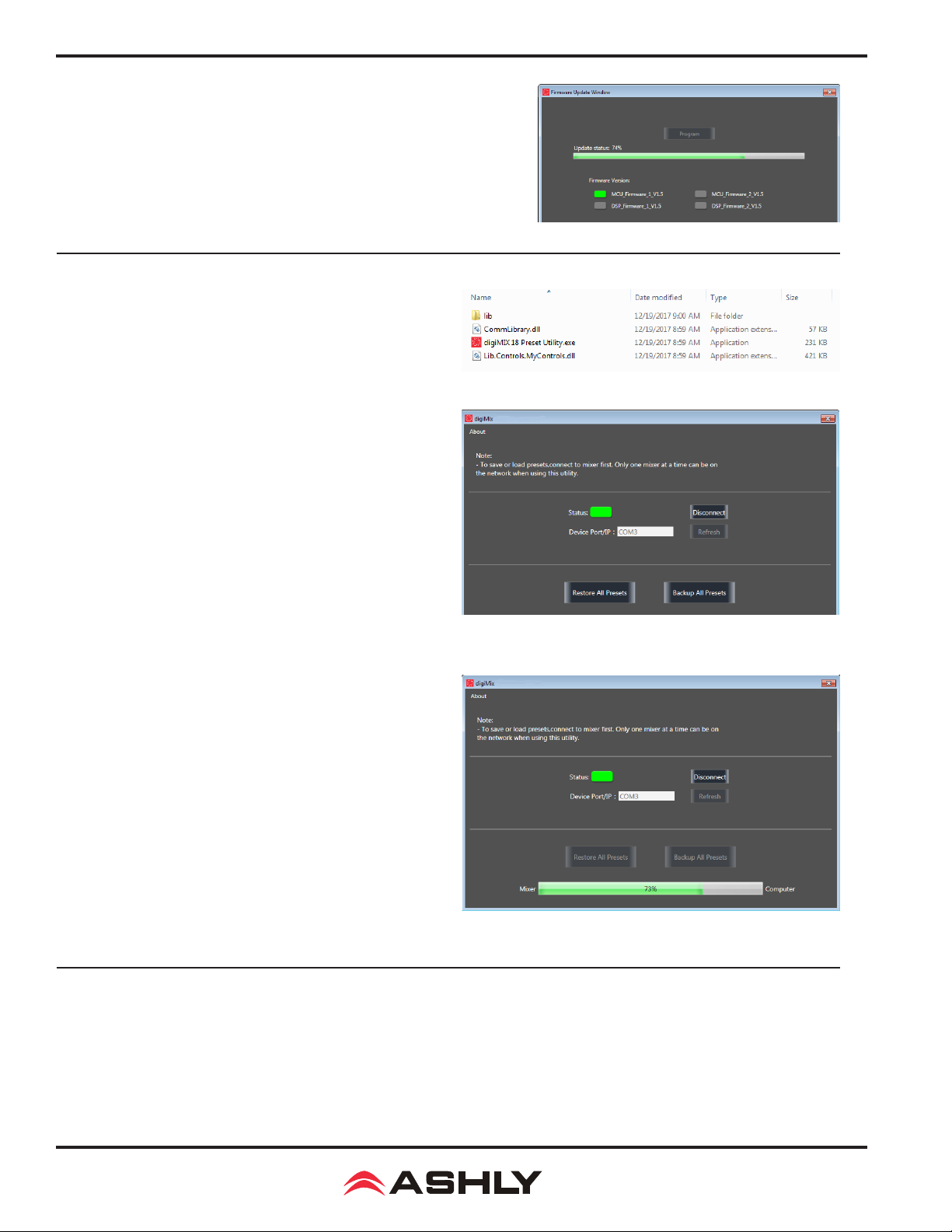
5) Click the "Update Firmware" button, then on the next screen click
"Program" (see gure 6.1c). The status bar will begin to show progress. Do
not turn off the mixer or interrupt the procedure until the entire process
is complete. The entire update takes about ve minutes.
6) When the update is complete, the mixer will automatically perform a
factory reset, erasing all mixer presets. Exit the software.
6.2 digiMIX18 Preset Utility
The digiMIX18 uses a stand-alone application to bulk-copy all
presets from the mixer to a computer or from computer to mixer.
Download the application from the Ashly website for Windows or
MAC. Note: Both USB and
for preset backup/restore.
Windows: Download and install "digiMIX 18 Preset Utility" le
bundle from the Ashly website Software/digiMIX18 downloads
section. Once installed there will be a root folder called "digiMIX
18 Preset Utility" containing an executable le named "digiMIX 18
Preset Utility.exe", plus two DLL les and a sub-folder called "Lib"
(see le list example at right). Click on the executable le to run the
program. The preset le will be saved as a *.ept le.
Ethernet data connection can be used
Figure 6.2a: digiMIX18 Preset Utility les (Windows)
Figure 6.1c: Firmware Update Status
MAC: Download the le "digiMIX 18 Preset Utility.dmg" from the
Ashly website Software/digiMIX Downloads section, and install.
The preset will be saved on a MAC as a *.mprt le.
Note: When restoring all preset les from computer to mixer, all
preset les on the mixer will be overwritten.
When the preset le transfer is complete, exit the software.
6.3 Factory Reset
Figure 6.2b: digiMIX18 Preset Utility
Figure 6.2c: digiMIX 8 Preset Utility status
To perform a factory reset, press and hold all three <Load + Save + Enter> buttons during power-up, then press "yes" on the
touchscreen when prompted. Note: This will erase all presets stored on the mixer. It will also unlock the mixer if locked, but
still preserves the previous password in memory.
22
Page 23

Operating Manual - digiMIX18 Digital Mixer
6.4 EZ-MODE
EZ-Mode provides a simple and secure user interface for a non-technical
person to adjust basic mixer functions with ease, locking out most other
mixer controls.
►
TIP:
All signal routing, levels, EQ, FX, DCA groups, and aux1-8 sends
must be congured ahead of time on the mixer before using EZ-Mode.
►
TIP:
DCA groups and aux1-8 outputs should be named on the mixer
rst (sec 2.34) for easier identication. You can also add icons to a channel
by pressing and holding the button above any EZ-Mode fader.
Press the mixer's EZ Mode button to access EZ-Mode, or press the mixer
system button then EZ-Mode button in the touchscreen shortcut section.
There are two pre-dened EZ-Mode mixers as shown below. Select
the EZ-Mode mixer you want to use, then press <Go To EZ Mixer>.
EZ-Mode Mixer #1: (see gure 6.4b) EZ-Mixer #1 provides faders for main L/R, DCA groups 1-4, and aux1-4, with on/off
switch and icon for each fader. DCA groups must be dened before using EZ-Mode (sec. 2.16)
EZ-Mode Mixer #2: (see gure 6.4c) EZ-Mixer #2 provides faders for main L/R, DCA groups 1-6, inputs 17-18, and aux1-8
outputs, with on/off switch and icon for each fader. Before using EZ-Mixer #2, DCA groups should be dened and named, and
aux1-8 outputs should also be named (sec. 2.34).
Figure 6.4b EZ-Mode Mixer #1
Figure 6.4a: EZ-Mode Main Screen
Figure 6.4c: EZ-Mode Mixer #2
EZ-Mode Icon Menu: (see gure 6.4d) In either EZ mixer, an icon can be assigned
to any fader to quickly identify its function. Press and hold the grey box above each
fader to view and select an icon from the pop-up icon table.
EZ-Mode Password: (see gure 6.4a) A password can be used in EZ-Mode to
prevent access to the full mixer while still allowing EZ-Mode control. The EZ-Mode
password is always the same as the mixer's password (sec. 5.4).
Additionally, the password can be used to independently lock EZ-Mode faders or
fader icons. The <EZ-Mode Password>, <Lock Icons>, and <Lock Faders> buttons
turn red when activated.
EZ-Mode is also offered on the Ashly digiMIX app for iPad for remote digiMIX18
control using a local wireless network connection (sec. 9). If a password is to be used
on the digiMIX iPad app, it must rst be entered into the mixer. Note that Only one
iPad at a time can be used to control the mixer.
►
TIP:
The iPad app provides the added feature of being able to use a user dened image or picture as an icon. (sec. 9.2).
Figure 6.4d: EZ-Mode Icon Menu
23
Page 24

Operating Manual - digiMIX18 Digital Mixer
6.5 Automix Assign
The automixer is used to automate the mixing of multiple speech
(not music) microphones to follow the dynamic nature of speech
dialog and attenuate idle microphones. Press the Automix button
below the touchscreen to assign inputs and activate the automixer.
Ashly Auto Mixer Technology
The automixer function is a "gain-sharing" type which
automatically makes smooth gain transitions on all assigned
automixer input channels to achieve a constant total system
gain. This gain-sharing method of automixing has been found
to be superior to gating automixers.
Input channels 1-16 can be individually enabled for the
automix. Enabled inputs must all be assigned to the main L/R output (sec. 2.39). Channels which are enabled for automix will
contribute to the automatic adjustment of other automix channel gains. Likewise, their channel level will be dynamically affected
by the signal level present on other automix channels. Manual mixer channels (those not enabled for automix) can still be mixed
in with automix channels, controlled by their fader setting. The fader on automix channels still controls the input level before
automatic mixing takes place so that more of the system gain can be applied to one channel versus another.
Automixer Setup
The following procedure is recommended for setting up most multi-microphone speech applications. The live mixing environment must
already be set up, with all mics wired to the mixer, assigned in the digiMIX18 to the main L/R outputs, placed where they will be used, mic
input gain controls set properly, and ampliers/speakers all set up.
1) Start with all mixer faders off. From the System menu, press the shortcut button for <Automix Assign>.
2) Assign the desired input channels to the automixer. Make sure the <Automix Active> button is pressed.
3) Select one of the assigned primary speech channels, or one which is centrally located. Slowly increase the fader for this one
channel just until feedback starts, then lower the fader 3 dB to stay comfortably below feedback. This sets the total automixer
system gain.
4) Now select and increase the other assigned input channel faders to the same position as the rst channel used in step 3. The
system will not feedback because the automixer will slowly attenuate the active channels as more channels are turned-on to
maintain a constant total system gain as set in step 3.
5) During the speech event, individual channel faders can still be raised or lowered to adjust for the weakness or strength of the
respective talkers even while the automixer is active.
6.5: Automix Assign
6.6 Crossfade Mode
Crossfade Mode allows the operator to easily fade back and forth
between two assigned channels (or two stereo linked channel pairs)
using either the Pan control or touchscreen crossfader control.
Crossfade Mode setup:
1) From the system menu, press the shortcut button for Crossfade
Mode.
2) Assign <Source A> and <Source B> channels.
3) Press the <Crossfade Active> button.
4) Crossfade Mode is now operating. The pan/touchscreen
control will fade between the two assigned channels.
5) To return to mixer mode, press the touchscreen <Mixer Mode> button, or toggle through mixer and crossfade modes using
the Mixer/Long Faders button next to the pan control.
When operating in normal mixer mode, the pan or touchscreen crossfade control always fades the selected channel right or left
as expected. When in crossfade mode with crossfade active, the control only fades between the two assigned source signals.
6.6: Crossfade Mode
24
Page 25
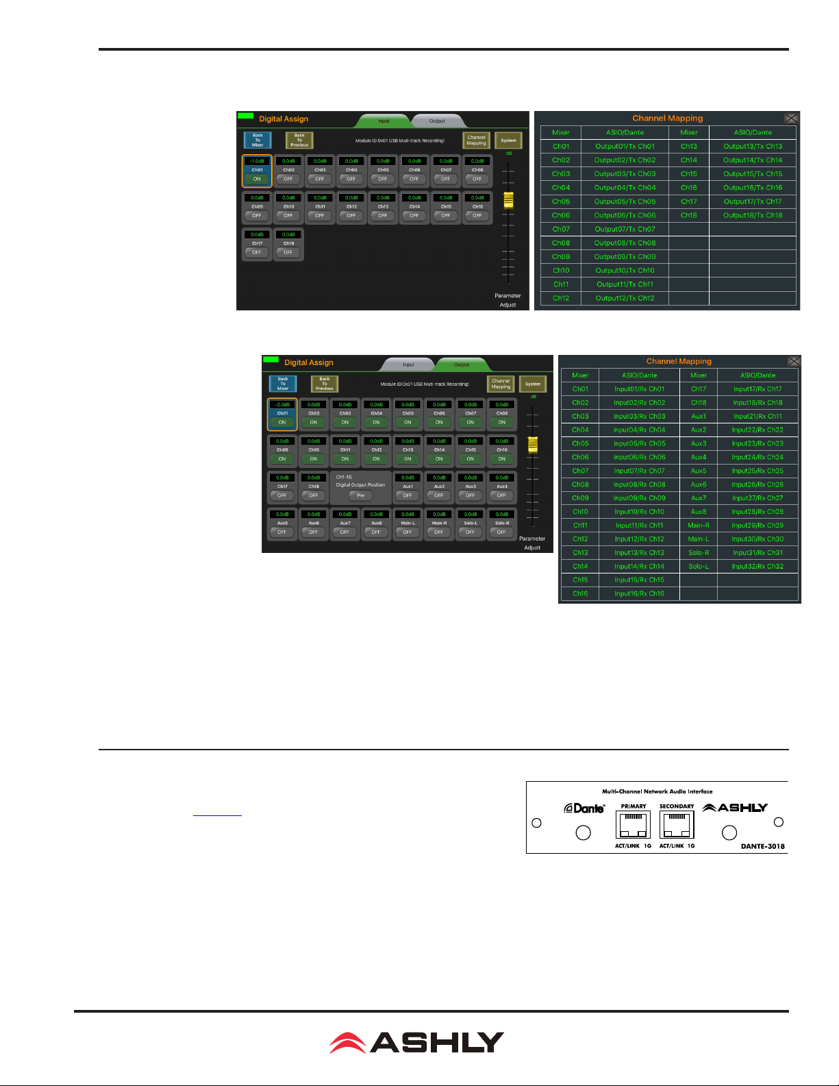
7 DIGITAL AUDIO
There are two optional
digital audio modules
a v a i l a b l e f o r t h e
digiMIX18, Dante-3018
and USB-3018. These
options provide digital
inputs to channels 1-18,
and digital outputs from
channels 1-18, main L/R,
aux1-8, and solo L/R.
Digital output from Mic
inputs 1-16 can be set
pre or post DSP. Digital
audio channel mapping
is internally fixed in
the mixer and cannot be
changed.
Digital input and output
channels are individually
en a b led, a nd s igna l
level is adjustable from
+10dB to -70dB. Press a
channel's On/Off button
to enable/disable digital
audio for that channel,
and use the parameter
adjust knob on the mixer
or touchscreen to adjust
level on the selected channel.
7b: Digital Output Assign and Mapping
Operating Manual - digiMIX18 Digital Mixer
7a: Digital Input Assign and Mapping
Digital inputs 1-18 are always pre-DSP and pre-fader. See the Block Diagram for details.
Digital outputs from Mic channels 1-16 can be group selected as pre or post DSP using the touchscreen. Whether pre or post DSP,
digital outputs from Mic channels 1-16 are always pre-fader and pre-mute. Note: the mixer will not allow d
simultaneously for the same Mic input channel if digital outputs are set post DSP.
Digital outputs from Line inputs 17-18 are always post-DSP, but pre-fader and pre-mute.
Digital outputs from main L/R, solo L/R, and aux1-8 outputs are always post-DSP and post-fader.
igital in and out to be used
7.1 Dante-3018 Option
Dante, created by Audinate, is an Ethernet based digital AV network technology
that uses existing network infrastructure for delivery of high performance,
high channel count audio signals.
With the optional Dante-3018 module installed, the digiMIX18 can be integrated
into a Dante digital audio network. The Dante-3018 resolution & sampling rate
is 24bit / 48KHZ. The Dante-3018 module can be eld installed and is sold
and shipped separately from the mixer along with installation instructions.
7.1 Dante-3018 Module
25
Page 26

Operating Manual - digiMIX18 Digital Mixer
7.1a Dante Controller:
digiMIX18 to receive and transmit audio with other Dante devices.
Conguration of Dante audio streams requires the use of Dante
Controller. This free software from Audinate is available for both
Windows® and Mac®. Dante Controller uses a simple matrix
(shown on next page) to connect Dante audio transmitters with
receivers. The Dante-3018 provides access for up to 18 digital
audio input channels and 30 digital audio output channels on the
digiMIX18.
Any Dante transmitter channel can be assigned to one or more
Dante-3018 receiver channels, but each Dante receiver channel
can have only one transmitter as its input source.
The Dante-3018 resolution & sampling rate is 24bit / 48KHZ.
Dante latency can be observed and congured for individual
devices within the Dante Controller Network Status tab. Note
that overall system latency will always adopt the slowest latency
found on devices linked in a transmitter/receiver stream.
Note that when the Dante-3
be the master clock.
The Dante-3018 module allows the
018
module is installed, it must always
7.1b Dante Virtual Soundcard (not shown): The
Dante Virtual Soundcard, purchased separately from Audinate,
allows a Windows or Mac computer to act as a Dante audio
source. Any sound the computer generates (background music,
announcements, VoIP sessions, etc.) can be routed to a Dante receiver
via the Dante controller.
NOTE: The Dante Virtual Soundcard audio stream may not automatically start up after digiMIX18 is powered on. If this happens,
cycle the mixer power again or restart the Dante audio stream.
7.1a: Dante Controller
7.2 USB-3018 Option
Digital audio workstations (DAW) often use multitrack USB audio streams for
I/O. The USB-3018 provides the digiMIX18 with 30 digital outputs and 18 inputs.
See section 7 for details on how digital input and output channels are routed
within the mixer, or refer to the block diagram in section 13.
The USB-3018 resolution & sampling rate is 24bit / 48KHZ.
Typical applications include multitrack recording from the mixer to a USB audio device, or playback of pre-recorded music from a USB
audio device. One particularly useful application is to record a band live onto a multi-track DAW, then play it back through the mixer
later for a "virtual" soundcheck before the musicians arrive. Visit the Ashly website knowledge base to review the Ashly application
note digiMIX-AN-2 for virtual soundcheck details.
8.1 USB-3018 Device Driver - Purchase the USB-3018 audio interface module from an Ashly dealer and install in the
mixer as instructed in section 3.15. An ASIO device driver is required for Windows computers but is not required for Mac.
The USB multi-channel ASIO Windows device driver can be downloaded from the Ashly website
section. Install the device driver on the PC before connecting it to the
device in the audio software's device list.
►
TIP: Detailed USB multichannel device driver installation and virtual soundcheck instructions are found in the Ashly application
note <digiMIX AN-2>, available in the Ashly website's digiMIX page App Notes section.
8.2 DAW Hardware Conguration - The
knowledge of your specic DAW hardware and software for proper conguration of channel mapping, recording, and playback properties.
digiMIX18
cannot re-congure it's internal channel mapping. You must have a working
digiMIX18
. The device driver will appear as an "ASIO" type
7.2 USB-3018 Module
digiMIX18
product page download
digiMIX18
26
Page 27

Operating Manual - digiMIX18 Digital Mixer
8 RACK EAR INSTALLATION
The digiMIX18 comes with rack ears that replace the molded plastic side pieces, allowing the mixer to be mounted to a standard 19"
equipment rack. Each plastic side is fastened with four 2.5mm Allen head screws. Before removing the plastic sides and installing the
rack ears, unplug the AC cord from the back of the mixer.
Step 1: Start with the removal of one plastic side. Unscrew the four 2.5mm Allen
head screws shown circled in the image to the right.
Step 2: The plastic sides have an illuminated Ashly logo embedded in the molded
plastic. This must be disconnected before the side can be completely removed.
Step 3: Gently disconnect the wire assembly header that powers the illuminated
Ashly logo. Pull apart by holding the white plastic header rather than the pulling
on the wires. Observe connector polarity when reconnecting later, and note that
the connector is indexed and can only be inserted one way.
Step 4: Carefully tuck the wire header connector assembly back inside the chassis
before attaching the rack ears.
Step 5: One rack ear is provided in the original shipping container for each side of
the mixer. Use the same screws removed in step #1 to attach the rack ears.
Step 6: Fasten the rack ear to the chassis using the four screws as shown.
Repeat this procedure for the other side. Store the removed plastic sides in the
mixer's original box for re-using later if necessary.
27
Page 28

Operating Manual - digiMIX18 Digital Mixer
9 iPAD REMOTE CONTROL
A free remote control iPad app called "Ashly digiMIX" is available from the
iTunes App Store. This app is used for all Ashly digiMIX products. Most mixer
touchscreen controls are duplicated on the app for wireless remote control of the
mixer, including EZ-Mode. Note: The digiMIX18 does not provide its own
Wi-Fi signal, so an existing network with Wi-Fi must be available for the
iPad. Only one iPad at a time can be used to control the mixer.
9.1 iPad Setup steps
9.1a -
Congure the iPad Wi-Fi to be on the same network subnet as the mixer
9.1b - Download, install and launch the Ashly digiMIX app with the mixer turned
on and connected to the network.
9.1c - On startup, the digiMIX app displays a device list of available IP addresses
for the mixer(s) on the network. Select an IP address and press <Connect>.
9.1d - In the resulting mixer display, a green rectangle in the upper
left corner indicates that the app is connected to a live mixer. It
turns grey if the connection is lost. If it is grey, press it to return
to the Device List used in step 9.1c. When connected, the iPad
always displays the same screen as the mixer. Changes to either
device will result in an identical change to the other device. The
fader on the left side of this screen always controls the currently
selected channel, or channel pair if two channels are stereo linked.
9.1e - To access the Assign, Channel, PEQ, Expander/Gate, or
Compressor/Limiter control screens for the currently selected
channel, press the "PEQ BOX" as shown in the upper left corner
of the mixer screen in the illustration to the right.
► TIP: If two channels are stereo linked, tapping the fader on the
left side of this screen alternately toggles between the two linked
channels, offering the ability to select and pan either channel
separately from within the Assign or Channel screens.
9.1f - To backup/restore presets, access EZ Mode, or use other
system functions from the iPad app, tap the <System> button
while in any of the control screens mentioned above in step 9.1e.
9.1d & 9.1e: digiMIX app Mixer Mode Display
9.1c: digiMIX app IP address selection
9.2 iPad EZ Mode
EZ Mode offers two congurations for basic remote control of the
mixer's main L/R and aux1-8 outputs and DCA groups. EZ-Mode
on the iPad allows the use of pictures as icons. Select an EZ-Mode
fader, press and hold the icon box above the fader, then press the
camera icon above the Select button. Select either the camera or
Photo library option to load the picture, then press ok. To remove
an icon or picture, repeat this process and select a blank icon. Other
than this feature, the two EZ Mode mixers function the same on
the iPad app as on the digiMIX18. See section 6.4 for complete
EZ Mode details. To use EZ Mode on the iPad, go to the system
page as described above in step 9.1f and press the EZ Mode button.
9.3 iPad EZ-Mode Password Protection
EZ-Mode will always use the same four-character password as the
mixer (sec. 5.4). The password must initially be entered on the
mixer, then can be used on the iPad to lock EZ-Mode faders or
fader icons. Passwords are case sensitive.
28
9.2: digiMIX app EZ-Mode
Page 29

Operating Manual - digiMIX18 Digital Mixer
10 TROUBLESHOOTING
10.1 No sound
Is the mic/line input cable plugged in and wired properly? If the mic is a condenser mic, is phantom power on? Is there activity
on the input LED meter? Is the input muted or its fader turned down? Is the input assigned or sent to the proper output? Is the
output level turned down or muted? Are the power amps off or their level controls turned down? Is the input assigned to a DCA
which is muted or turned down? Are the HPF or LPF lters properly set in the PEQ section to allow the desired passband? Is
the noise gate engaged and its threshold set so high that it always shuts off the signal?
10.2 Distorted sound
Is the input LED Clip light on? If so, turn down the input source or reduce the input trim control until the input LED signal
peaks between 0-4 on the input meter bar. If there is still distortion, is the input fader too high? Is the Comp/Limiter engaged
and its gain control set too high? Does a PEQ or GEQ lter have too much boost?
10.3 Excessive hiss
Hiss is caused by insufcient gain on the input stages and too much gain in the output stage. Be sure to have a strong input
signal, adjusting the input trim control so the signal peaks are between 0 and 4 on the input LED meter bar.
10.4 Control does nothing
Is the desired input, output, or FX selected? If an expander/gate or comp/limiter control does not work, is the function turned
ON or ratio set properly? If the PEQ or GEQ controls do nothing, is the function turned on? Is the Bypass button lit up?
10.5 No sound in headphones when using solo button
Are the headphones turned down? If the PFL button is pressed, is there sufcient input signal? PFL means "pre-fader listen", so
the position of that channel's fader will not affect solo. If PFL is off, is the channel fader turned down? If the input is assigned
to a DCA and that DCA turned down or muted?
10.6 FX not working
Three things are necessary for an FX to work properly.
1) FX must be properly dened. Press FX1 or FX2 to dene, edit, or load an effect. Make sure the <Wet-Dry> mix control is properly set.
2) Inputs must have their signal sent to the FX1 or FX2 bus. Select an input and use the FX Send button to send pre or post-fader
signal to the FX1 or FX2 bus.
3) FX1-2 must always be assigned or sent to main L/R or aux1-8 outputs. Select FX1 or FX2, then press the Assign button to
send it to the main L/R or aux1-8 outputs.
10.7 iPad digiMIX app/network troubleshooting
1) There are no IP addresses in my Device List. Is the mixer turned on and properly connected to the same network that the
wi router is connected to? Is the iPad's wi turned on? The app may have timed out, so refresh the device list by rst pressing
"Demo", then press the small grey box in the upper left corner of the resulting mixer screen to return to the startup page. This
causes the app to re-discover all online mixers and display their IP address.
2) The app won't control the mixer. Is there more than one mixer on the network? Several mixers can be connected to the
same network for remote iPad control, however the digiMIX app can only connect to one mixer at a time. Make sure you are
connected to the right mixer. On start-up, the digiMIX app discovers and lists all available mixers by their IP address. Select an IP
address from the Device List and press "Connect" to control that mixer. Once connected, the app shows a green box in the upper
left corner. A grey box means the connection has been lost. To control a different mixer, the app must be closed and re-launched.
3) Can I use more than on iPad on one mixer? No, only one iPad at a time can be used with a mixer. If a second iPad connects
with that mixer, it takes over control. The last iPad connected always has control.
4) What are the digiMIX18 Network communication settings? ● Default static IP is 192.168.2.1 ● Set for automatic DHCP
conguration ● Uses Port 5000 ● Uses both UDP and TCP/IP
29
Page 30

Operating Manual - digiMIX18 Digital Mixer
11 SPECIFICATIONS 0dBu = 0.775Vrms
Microphone Input . . . . . . . . . . . . . . . . . . . . . . . . . . . . . . . . . . . . . . . . . .Class-A discrete balanced, 7.3k Ohm input impedance
Frequency response to main L/R output . . . . . . . . . . . . . . . . . . . . . . . . . . 20Hz ~ 20kHz +0.0/-0.5dB
Distortion (THD&N) to main L/R output . . . . . . . . . . . . . . . . . . . . . . . . . <0.01% at 0dBu, 20Hz ~ 20kHz
Equivalent input noise . . . . . . . . . . . . . . . . . . . . . . . . . . . . . . . . . . . . . . . .-126dBu, unweighted, 20Hz ~ 20kHz, 150 Ohm source
Gain (trim) . . . . . . . . . . . . . . . . . . . . . . . . . . . . . . . . . . . . . . . . . . . . . . . . .0 dB ~ +50dB
Maximum input level. . . . . . . . . . . . . . . . . . . . . . . . . . . . . . . . . . . . . . . . . +20dBu, balanced
Phantom power (individually selectable on channels 1-16) . . . . . . . . . . . +48VDC +0/-4V, maximum 14mA per channel
Line input . . . . . . . . . . . . . . . . . . . . . . . . . . . . . . . . . . . . . . . . . . . . . . . . .Balanced, 75k Ohm input impedance
Frequency response to main L/R output . . . . . . . . . . . . . . . . . . . . . . . . . . 20Hz ~ 20kHz at 0dBu, +0/-1.5dB
Distortion (THD&N) to main L/R output . . . . . . . . . . . . . . . . . . . . . . . . . <0.01% at 0dBu, 20Hz ~ 20kHz
Gain (trim) . . . . . . . . . . . . . . . . . . . . . . . . . . . . . . . . . . . . . . . . . . . . . . . . .-20dB ~ +30dB
Maximum input level. . . . . . . . . . . . . . . . . . . . . . . . . . . . . . . . . . . . . . . . . +20dBu
TRS Insert (ch1-8 only) . . . . . . . . . . . . . . . . . . . . . . . . . . . . . . . . . . . . . . Unbalanced, tip = send, ring = return
Maximum output level. . . . . . . . . . . . . . . . . . . . . . . . . . . . . . . . . . . . . . . . +20dBu, 120 Ohm source impedance
Maximum input level. . . . . . . . . . . . . . . . . . . . . . . . . . . . . . . . . . . . . . . . . +20dBu, 5.0k Ohm input impedance
Stereo Line Inputs 17~18 . . . . . . . . . . . . . . . . . . . . . . . . . . . . . . . . . . . .Balanced stereo pair, 27k Ohm input impedance
Frequency response to main L/R output . . . . . . . . . . . . . . . . . . . . . . . . . . 20Hz ~ 20kHz, +0/-0.05dB
Distortion (THD&N) unity gain to main L/R output. . . . . . . . . . . . . . . . . <0.07% at 0dBu, 20Hz ~ 20kHz
Gain . . . . . . . . . . . . . . . . . . . . . . . . . . . . . . . . . . . . . . . . . . . . . . . . . .-∞ ~ +10dB
Maximum input level. . . . . . . . . . . . . . . . . . . . . . . . . . . . . . . . . . . . . . . . . +20dBu
Maximum Output levels (240 Ohm source impedance)
Main L/R outputs. . . . . . . . . . . . . . . . . . . . . . . . . . . . . . . . . . . . . . . . . . . . Balanced XLR and TRS phone jack, +20dBu
Aux 1~8 outputs. . . . . . . . . . . . . . . . . . . . . . . . . . . . . . . . . . . . . . . . . . . . . Pseudo-Balanced TRS phone jack, +20dBu
Control room outputs. . . . . . . . . . . . . . . . . . . . . . . . . . . . . . . . . . . . . . . . . Pseudo-Balanced TRS phone jack, +20dBu
Residual output noise (one mic input assigned at 0dB). . . . . . . . . . . . . . . -88dBu, 20Hz-20kHz, unweighted
Residual output noise (all 16 mic inputs assigned at 0dB) . . . . . . . . . . . . -78dBu, 20Hz-20kHz, unweighted
Residual output noise (all 18 inputs assigned at 0dB). . . . . . . . . . . . . . . . -78dBu, 20Hz-20kHz, unweighted
Crosstalk
Adjacent channels (1kHz) . . . . . . . . . . . . . . . . . . . . . . . . . . . . . . . . . . . . . -82dB
Noise (bus noise, adjacent channels 20Hz ~ 20kHz). . . . . . . . . . . . . . . . .-70dB
Channel DSP Functions:
Polarity Invert (Inputs, main L/R, aux1-8, FX1-2) . . . . . . . . . . . . . . . . .Per channel, On/Off
Delay Time (Inputs, main L/R, aux1-8, FX1-2) . . . . . . . . . . . . . . . . . . . .Per channel, 0-300ms in 0.2 ms increments
Noise Gate/Expander. . . . . . . . . . . . . . . . . . . . . . . . . . . . . . . . . . . . . . . . Inputs, FX1-2
Threshold range . . . . . . . . . . . . . . . . . . . . . . . . . . . . . . . . . . . . . . . . . . . . .-84dB ~ 0dBFS
Attack time . . . . . . . . . . . . . . . . . . . . . . . . . . . . . . . . . . . . . . . . . . . . . . . . . 0.5mS ~ 200mS
Release time. . . . . . . . . . . . . . . . . . . . . . . . . . . . . . . . . . . . . . . . . . . . . . . . 10mS ~ 1,000mS
Ratio . . . . . . . . . . . . . . . . . . . . . . . . . . . . . . . . . . . . . . . . . . . . . . . . . .1:1 ~ ∞
Compressor/Limiter . . . . . . . . . . . . . . . . . . . . . . . . . . . . . . . . . . . . . . . .Inputs, main L/R, aux1-8, FX1-2
Threshold range . . . . . . . . . . . . . . . . . . . . . . . . . . . . . . . . . . . . . . . . . . . . .-50dB ~ 0dBFS
Attack time . . . . . . . . . . . . . . . . . . . . . . . . . . . . . . . . . . . . . . . . . . . . . . . . . 10mS ~ 150mS
Release time. . . . . . . . . . . . . . . . . . . . . . . . . . . . . . . . . . . . . . . . . . . . . . . . 10mS ~ 1,000mS
Ratio . . . . . . . . . . . . . . . . . . . . . . . . . . . . . . . . . . . . . . . . . . . . . . . . . .1:1 ~ ∞
Gain . . . . . . . . . . . . . . . . . . . . . . . . . . . . . . . . . . . . . . . . . . . . . . . . . .0dB ~ +24dB
PEQ (parametric EQ) . . . . . . . . . . . . . . . . . . . . . . . . . . . . . . . . . . . . . . . Inputs, main L/R, aux1-8, FX1-2
EQ1, EQ2, EQ3, EQ4 lter type . . . . . . . . . . . . . . . . . . . . . . . . . . . . . . . . Parametric, low shelf, high shelf
Parametric lters . . . . . . . . . . . . . . . . . . . . . . . . . . . . . . . . . . . . . . . . . . . . 20.6Hz ~ 20kHz, Q 0.4 ~ 24, boost/cut ±24dB
Shelving lters . . . . . . . . . . . . . . . . . . . . . . . . . . . . . . . . . . . . . . . . . . . . . . 20.6Hz ~ 20kHz, boost/cut ±24dB
HPF and LPF . . . . . . . . . . . . . . . . . . . . . . . . . . . . . . . . . . . . . . . . . . . . . . .20.6Hz ~ 20kHz, 20 lter types
30
Page 31

Operating Manual - digiMIX18 Digital Mixer
HPF and LPF lter types . . . . . . . . . . . . . . . . . . . . . . . . . . . . . . . . . . . . . .Bypass, Butterworth (BW) 6dB/oct, Bessel (BS) 6dB/oct,
BW 12dB/oct, BS 12dB/oct, Linkowitz/Riley (LR) 12dB/oct,
BW 18dB/oct, BS 18dB/oct, BW 24dB/oct, BS 24dB/oct,
LR 24dB/oct, BW 30dB/oct, BS 30dB/oct, BW 36dB/oct,
BS 36dB/oct, LR 36dB/oct, BW 42dB/oct, BS 42dB/oct,
BW 48dB/oct, BS 48dB/oct, LR 48dB/oct
GEQ (graphic EQ) . . . . . . . . . . . . . . . . . . . . . . . . . . . . . . . . . . . . . . . . . . Main L/R, aux1-8 outputs
Filter type. . . . . . . . . . . . . . . . . . . . . . . . . . . . . . . . . . . . . . . . . . . . . . . . . . 31 band, constant Q, boost/cut ±24dB
FX (effects) . . . . . . . . . . . . . . . . . . . . . . . . . . . . . . . . . . . . . . . . . . . . . . . .FX1-2 input Sends from all 18 inputs,
FX1-2 output Assigns to main L/R, aux1-8
Effect types . . . . . . . . . . . . . . . . . . . . . . . . . . . . . . . . . . . . . . . . . . . . . .
See chart in section 4.6 for complete effects details
Automixer (for speech only) . . . . . . . . . . . . . . . . . . . . . . . . . . . . . . . . . . . Gain-sharing type, individual assignment of channels 1-16
Crossfade mode (system screen) . . . . . . . . . . . . . . . . . . . . . . . . . . . . . . .
Stereo link. . . . . . . . . . . . . . . . . . . . . . . . . . . . . . . . . . . . . . . . . . . . . . . . . Inputs 1-16, aux1-8 outputs, paired only as 1-2, 3-4, 5-6 etc.
DCA groups . . . . . . . . . . . . . . . . . . . . . . . . . . . . . . . . . . . . . . . . . . . . . . . 6 groups, level, mute, solo
Password Security . . . . . . . . . . . . . . . . . . . . . . . . . . . . . . . . . . . . . . . . . . Mixer lock, unlock, 4-character password, case sensitive
EZ Mode (simplied individual fader adjust, on/off, icon assign) . . . . . EZ Mixer #1: Main L/R, DCA1-4, aux1-4, password lock
EZ Mixer #2: Main L/R, DCA1-6, aux1-8, ch17-18, password lock
Preset types . . . . . . . . . . . . . . . . . . . . . . . . . . . . . . . . . . . . . . . . . . . . . . . . Scene (24), DSP channel (48), FX (104), GEQ (48)
Reverbs (3), delay (1200ms), tremolo, ange, chorus, combinations
Use pan control to fade between any two assigned inputs, outputs, or FX
A-D converter dynamic range . . . . . . . . . . . . . . . . . . . . . . . . . . . . . . . . . . 104dB, unweighted
Internal processor. . . . . . . . . . . . . . . . . . . . . . . . . . . . . . . . . . . . . . . . . . . . 32-bit oating point
D-A converter dynamic range . . . . . . . . . . . . . . . . . . . . . . . . . . . . . . . . . .105dB, unweighted
ADC/DAC bit depth and sampling rate . . . . . . . . . . . . . . . . . . . . . . . . . . .24-bit / 48kHz
Latency . . . . . . . . . . . . . . . . . . . . . . . . . . . . . . . . . . . . . . . . . . . . . . . . . .5.8mS, 1kHz, analog input to analog output
Optional digital audio modules. . . . . . . . . . . . . . . . . . . . . . . . . . . . . . . . Dante-3018, USB-3018 (eld installable)
Dante-3018 bit depth, sampling rate . . . . . . . . . . . . . . . . . . . . . . . . . . . . . 24bit, 48kHz
USB-3018 bit depth, sampling rate . . . . . . . . . . . . . . . . . . . . . . . . . . . . . .24bit, 48kHz
DigiMIX18 digital in, ch1-18 (pre-DSP). . . . . . . . . . . . . . . . . . . . . . . . . . On/Off, level control +10dB to -70dB, off, xed channel mapping
DigiMIX18 digital out ch1-16 (selectable as group pre or *post DSP). . .On/Off, +10dB to -70dB level, xed channel mapping
DigiMIX18
*Note: Digital in and out can not be used simultaneously for the same channel if digital out is set to post DSP.
Software/Utilities/Drivers
Remote mixer control app for iPad® . . . . . . . . . . . . . . . . . . . . . . . . . . . . . "Ashly digiMIX" app, free from iTunes App Store
Firmware update software for Windows or Mac. . . . . . . . . . . . . . . . . . . .
Preset backup/restore for Windows or Mac. . . . . . . . . . . . . . . . . . . . . . . .
USB COM device driver for connecting digiMIX18 utility (if required) Available on
ASIO driver (required if using USB-3018 option with Windows) . . . . . .
MAC address . . . . . . . . . . . . . . . . . . . . . . . . . . . . . . . . . . . . . . . . . . . . . . .printed on serial number sticker on back of mixer
Ethernet communication defaults . . . . . . . . . . . . . . . . . . . . . . . . . . . . . . .IP 192.168.2.1, auto-DHCP, port 5000, uses both UDP and TCP/IP
AC mains . . . . . . . . . . . . . . . . . . . . . . . . . . . . . . . . . . . . . . . . . . . . . . . . . . 100-240VAC 50/60Hz, 120W max
Operating free-air temperature range. . . . . . . . . . . . . . . . . . . . . . . . . . . . . 41°F ~ 113°F (5°C ~ 45°C)
Storage temperature range . . . . . . . . . . . . . . . . . . . . . . . . . . . . . . . . . . . . . -4°F ~ 140°F (-20°C ~ 60°C)
Unit dimensions . . . . . . . . . . . . . . . . . . . . . . . . . . . . . . . . . . . . . . . . . . . . . 19.3"L x 5.65"W x 14.0"H (48.6cm x 14.4cm x 35.6cm)
Shipping dimensions . . . . . . . . . . . . . . . . . . . . . . . . . . . . . . . . . . . . . . . . . 22.0"L x 8.15"W x 17.1"H (55.9cm x 20.7cm x 43.4cm)
Unit weight . . . . . . . . . . . . . . . . . . . . . . . . . . . . . . . . . . . . . . . . . . . . . . . .17.0 lbs (7.7kg)
Shipping weight . . . . . . . . . . . . . . . . . . . . . . . . . . . . . . . . . . . . . . . . . . . . . 21.0 lbs (9.5kg)
Dante-3018 shipping weight . . . . . . . . . . . . . . . . . . . . . . . . . . . . . . . . . . . 0.42 lbs (0.19kg)
Dante-3018 shipping dimensions. . . . . . . . . . . . . . . . . . . . . . . . . . . . . . . .6.02"L x 1.85"W x 7.09"H (15.3cm x 4.70cm x 18.0cm)
USB-3018 shipping weight . . . . . . . . . . . . . . . . . . . . . . . . . . . . . . . . . . . . 0.47 lbs (0.21kg)
USB-3018 shipping dimensions . . . . . . . . . . . . . . . . . . . . . . . . . . . . . . . .6.02"L x 1.85"W x 7.09"H (15.3cm x 4.70cm x 18.0cm)
Compliance/safety . . . . . . . . . . . . . . . . . . . . . . . . . . . . . . . . . . . . . . . . . . .cTUVus, CE, FCC, RoHs
Limited warranty . . . . . . . . . . . . . . . . . . . . . . . . . . . . . . . . . . . . . . . . . . . .5 year (3 year on touchscreen and motorized fader)
digital out ch17-18, main L/R, aux1-8. solo (post DSP only). .
On/Off, +10dB to -70dB level, xed channel mapping
"digiMIX18 Firmware Utility" a
"digiMIX18 Preset Utility" a
Ashly website for Windows or Mac
Available on Ashly website for Windows, not required for Mac
vailable on
vailable on
Ashly website
Ashly website
31
Page 32

Operating Manual - digiMIX18 Digital Mixer
12 DIMENSIONS
32
Page 33

Operating Manual - digiMIX18 Digital Mixer
13 BLOCK DIAGRAM
33
Page 34

Operating Manual - digiMIX18 Digital Mixer
14 Ashly Audio Inc. LIMITED WARRANTY (USA ONLY)
(For other countries, please contact your respective distributor or dealer from where the unit was rst purchased.)
For units purchased in the USA, warranty service for this unit shall be provided by ASHLY AUDIO, INC. in accordance with the following warranty statement.
ASHLY AUDIO, INC. warrants to the owner of this product that it will be free from defects in workmanship and materials for a period of FIVE years from the original-date-of-purchase, with the exception of touch-screen displays and
motorized faders which are warrantied for THREE years from the original-date-of-purchase.
ASHLY AUDIO INC. will without charge, repair or replace at its discretion, any defective product or component parts
upon prepaid delivery of the product to the ASHLY AUDIO, INC. factory service department, accompanied with a
proof of original-date-of-purchase in the form of a valid sales receipt. This warranty gives you specic legal rights,
and you may also have other rights, which vary from state to state.
EXCLUSIONS: This warranty does not apply in the event of misuse, neglect, or as a result of unauthorized alterations
or repairs made to the product. This warranty is void if the serial number is altered, defaced, or removed. ASHLY
AUDIO, INC. reserves the right to make changes in design, or make additions to, or improvements upon, this product
without any obligation to install the same on products previously manufactured.
Any implied warranties, which may arise under the operation of state law, shall be effective only for FIVE years
(THREE years for touch-screen displays and motorized faders) from the original-date-of-purchase of the product.
ASHLY AUDIO, INC. shall be obligated to only correct defects in the product itself. ASHLY AUDIO, INC. is not liable for any damage or injury, which may result from, or be incidental to, or a consequence of, such defects. Some
states do not allow limitations on how long an implied warranty lasts, or the exclusion, or limitation of incidental or
consequential damages, so the above limitations or exclusions may not apply to you.
OBTAINING WARRANTY SERVICE:
For warranty service in the United States, please follow this procedure:
1) Please return the product to ASHLY AUDIO, INC. freight prepaid, with a written statement describing the defect
and application that the product is used in. ASHLY AUDIO, INC. will examine the product and perform any necessary
service, including replacement of defective parts, at no further cost to you.
2) Please ship your product to:
ASHLY AUDIO, INC.
Attention: Service Department
847 Holt Road
Webster, NY 14580-9103
34
Page 35

Operating Manual - digiMIX18 Digital Mixer
This page intenonally le blank
35
Page 36

Operating Manual - digiMIX18 Digital Mixer
ASHLY AUDIO INC. 847 Holt Road Webster, NY 14580-9103 USA
Phone: (585) 872-0010 Fax: (585) 872-0739
Toll Free (800) 828-6308 ashly.com
2018 Ashly Audio, Inc. All rights reserved worldwide.
Ashly Audio is a division of Jam Industries, Ltd.
All features, specications, and graphical representations are
subject to change or improvement without notice.
DM18 R01 0118
 Loading...