

Page 1

CA Series
Power Amplifiers.
Our most
efficient amp
series yet!
D-MAX Class D
technology,
Dynamic Power
Factor Correction,
and SailFlow
cooling.
-MAX Class D technology
and Dynamic Power Factor
D
Correction make our CA series
the most efficient amplifiers we
(or anyone else) have offered
% more efficient than one of
our most popular competitors.
Efficiency definitely counts
when the electrical power bill
comes. But our CA Series have
another advantage over other
amps of the same power: you
can run any TWO CA’s on a
single 20-amp line. If your proj-
ect needs two amps, you don’t
have to call a $100/hr electrician to add a second 20-amp
feed.
CA amps sound superb
even when driven hard and stay
cooler than most, thanks
to straight-thru, unimpeded
SailFlow cooling.
CA-502
C A-1. 0 2
C A-1. 5 2
back
panel
CA-504
C A -1. 0 4
C A -1. 5 4
back
panel
CA-502
C A -1.0 2
C A -1.5 2
front
panel
CA-504
C A -1.0 4
C A -1.5 4
front
panel
DATA
SHEET
on
PAGE THREE
Page 2

Page 2 of 4
CA Series
This page
intentionally
left blank*.
High-Efficiency Power Amplifiers
Data Sheet
begins on the
next page.
*Done so that those fortunate to have printers with
2-sided printing capabilities can print out the Data Sheet
on one sheet of paper.
Page 3

Page 3 of 5
CA Series
shly’s proprietary D-MAX™
A
technology takes Class D performance and efficiency to a whole
new level. By starting with a clean
slate, our engineers were able to
apply cutting-edge design practices
and state-of-the-art components to
the most efficient amp we’ve tested
thus far.
The pay-off is less heat, lower
distortion, more stable operation and
greater reliability. Bulky heat sinks
are no longer required. Instead, we
optimized active air cooling using our
newly developed SailFlow™ design,
which moves the air along a selective
path, to where it’s needed most.
Coupled with our ultra-high-speed
switching power-supply and intelligent power management, all the
transient impact and spatial detail
of your sound is preserved and your
speakers will never be happier.
Light-weight and power-efficient,
CA will never pull more power than
your wall outlet delivers. No more
worry about driving speakers to
the brink of destruction or tripping
breakers.
High-Efficiency Power Amplifiers
CA Series Model Chs 2Ω
CA-502
CA-1.02
CA-1. 52
CA-504
2 500W
2 1000W
2 1 500W
4 500W
4Ω
8Ω
500W
250W
1000W
500W
1500W
750W
500W
250W
8Ω
bridged Constant Voltage
1 000W
2000W
3000W
1000W
CA-502
C A-1. 0 2
C A-1. 5 2
back
panel
CA-504
C A -1.0 4
C A -1.5 4
back
panel
1 000W
bridged 70V
1 000W 70V
2000W 100V bridged
1500W 70V
3000W
100V bridged
1000W
bridged 70V
CA-502
C A -1.0 2
C A -1.5 2
front
panel
CA-504
C A -1.0 4
C A -1.5 4
front
panel
❚ 2 and 4-channel models
❚ 500 to 1500W @4Ω
❚ Stable 2Ω rating
❚ 70/100V capability
❚ Ultra efficient D-MAX Class D design
❚ DPFC (Dynamic Power
Factor Correction)
❚ Selectable amp gain per channel
❚ Adjustable front panel
Input Gain per channel
with lock-out
❚ Bi-lateral SailFlow cooling
CA-1.04
CA-1. 54
❚ Installer-friendly Euroblock and XLR
combo connectors
❚ Switchable HPF and Clip
Limiter per channel
❚ CV remote ports per channel
❚ Solid metal front panel
❚ 5-year Warranty
4 1000W
4 1 500 W
1000W
500W
1500W
750W
Sales@Ashly.com • www.Ashly.com
2000W
3000W
US toll-free +1.585.872.0010
Fax +1.585.872.0739
1000W 70V
2000W 1 00V bridged
1500W 70V
3000W
100V bridged
Page 4
CA Series
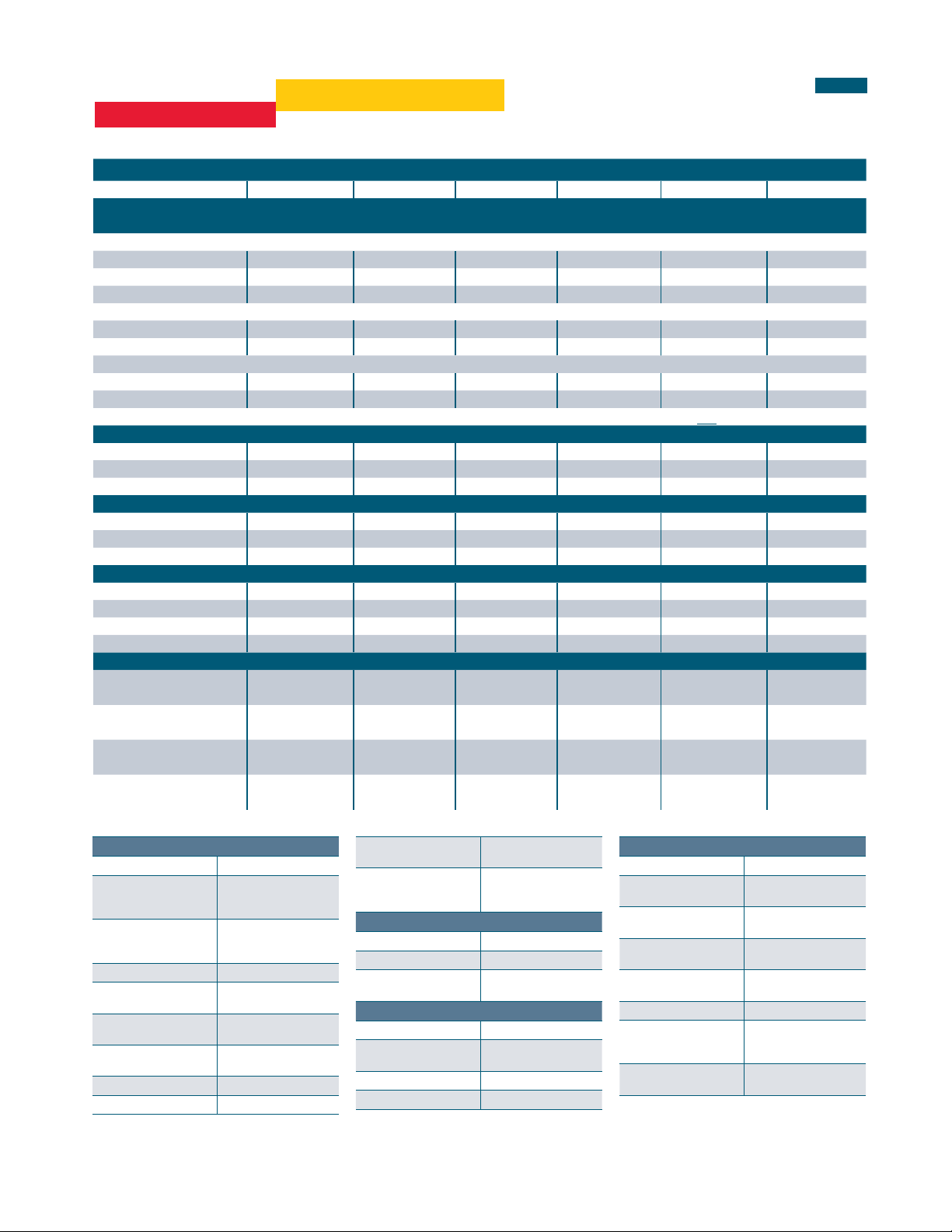
7 Specifications
General Power Amplifier Specifications (0dBu = 0.775V rms)
Amplifier Model CA1.54 CA1.52 CA1.04 CA1.02 CA504 CA502
Maximum Output Power - in Watts
CEA-2006/490A, 20ms 1kHz 1%THD+N, 480ms 1kHz -20dB, 120VAC, all channels driven at rated load
Low Z output, per channel
2 Ohm 1500 1500 1000 1000 500 500
4 Ohm 1500 1500 1000 1000 500 500
8 Ohm 750 750 500 500 250 250
Low Z output, per bridged channel pair*
4 Ohm 3000* 3000* 2000* 2000* 1000* 1000*
8 Ohm 1500* 1500* 1000* 1000* 500 500
70V/100V* output
70V 1500 (direct) 1500 (direct) 1000 (direct) 1000 (direct) 1000* (bridged) 1000* (bridged)
100V 3000* (bridged) 3000* (bridged) 2000* (bridged) 2000* (bridged) 1000* (bridged) 1000* (bridged)
Total Power Draw - in Watts, all channels driven, 1/8 power sinewave
Standby 22 13 19 10 17 8
Idle (no signal) 100 31 70 40 34 17
1/8 max power 975 485 675 335 345 172
Total Current Draw - in Amps, all channels driven, 1/8 power sinewave, 120VAC (divide by 2 for 240VAC)
Standby mode 0.39 0.24 0.37 0.21 0.35 0.2
Idle (no signal) 0.68 0.36 0.64 0.34 0.5 0.27
1/8 max power 8.9 4.2 6 3 3 1.5
Total Thermal Dissipation - in BTU/hour with typical input, all channels driven, 120VAC
Standby mode 76 44 65 32 57 28
Idle (no signal) 209 105 184 96 115 57
1/8 max power, 4 Ohm 648 314 474 229 266 120
1/8 max power, 2 Ohm 754 355 576 269 304 148
Input Sensitivity - in Volts and dBu, per back panel DIP Switch gain settings
@26dB gain 2.0V
@32dB gain 1.0V
@38dB gain 0.5V
@1.4V gain 1.4V
High-Efficiency Power Amplifiers
*May require Class 3 speaker wiring, all others use Class 2 wiring. See section 2.3
(+8.2dBu)
(+2.2dBu)
(+3.8dBu)
(+5.1dBu)
2.0V
(+8.2dBu)
1.0V
(+2.2dBu)
0.5V
(+3.8dBu)
1.4V
(+5.1dBu)
2.7V
(+11dBu)
1.4V
(+5.1dBu)
0.68V
(-1.1dBu)
1.4V
(+5.1dBu)
2.7V
(+11dBu)
1.4V
(+5.1dBu)
0.68V
(-1.1dBu)
1.4V
(+5.1dBu)
3.9V
(+14dBu)
1.9V
(+7.8dBu)
0.97V
(+2dBu)
1.4V
(+5.1dBu)
Page 4 of 5
3.9V
(+14dBu)
1.9V
(+7.8dBu)
0.97V
(+2dBu)
1.4V
(+5.1dBu)
Electronic
Distortion (SMPTE, typical) <0.5%
Distortion (THD-N, typical,
8 Ohm, 10dB b elow rated
power, 20Hz-20kHz
Signal to N oise, 26dB input
sensitivity, 20Hz-20kHz,
unweighted
Frequency Response 20Hz-20kHz, ±0.05dB
Channel Separation
(dB from full o utput, 1kH z)
Damping Factor
(8 Ohm load, <1k Hz)
Balanced Input Connector
(per channel)
Input Impedance 10k Ohm
Maximum Input Level +21 dBu
<0.5%
>98dB (50 x models)
>101dB (1.0x models)
>103dB (1.5 x models)
-75d B
>25 0
Eurobl ock (3.5mm),
¼” TRS and X LR Combo jack
Bridge Mode Switch
(per channel pair)
Remote D C Level Contr ol
(G, CV, V+ per channel )
In for bri dged mode, Out
for stereo
Eurobl ock (3.5mm),
V+ is fully on , G is fully
attenuated
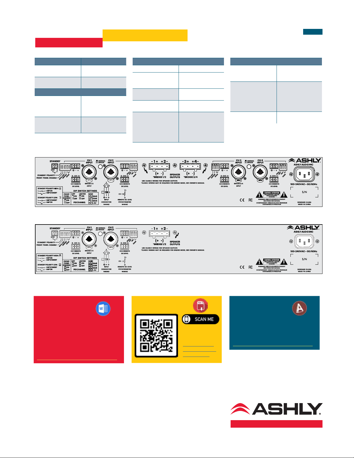
DIP Switch settings (per channel)
Switc hes 1-2: Input Gain 2 6dB, 32dB, 38dB , 1.4V
Switc h 3: Output Clip Li miter On, Off
Switc h 4: Input High Pass
Filter
80Hz 2n d order HPF,
On, Off
DIP Switch settings (global)
Switc h 5: Front Panel Di sable On, O ff
Switc h 6: Standby Pola rity H igh (standby whe n open),
Standby Contact Closure Eurobl ock (3.5mm)
Speaker Output Connector Euroblock (7.62mm)
Low (standby when closed)
Front Panel Indicators
Power S witch LED (whi te) On, Off, Standby (flashing)
Clip/Mu te LED (red) On at 95% m ax output
Signal L ED (green) On at 25% max o utput (12dB
Curren t LED (green) On at >2 Amps to sp eaker
Temp LED (yellow) On when therm al counter-
Bridge L ED (green) Per Chann el Pair - On, Off
Prote ct LED (red) see
troubleshooting section for
protec t LED error co des
Disable LED (yellow) On when fr ont panel
(0.5dB below m ax), Mute
below max)
load
measures are being applied
On for faul t condition
counter-measures or shutdown, Of f
contr ols are disabled, O ff
Page 5
CA Series
High-Efficiency Power Amplifiers
Page 5 of 5
Controls
Attenuators Per channel: fr ont panel,
Fully of f = Mute
Remote C ontrol Opti ons WR-1, WR-1.1 DC le vel
control
Protection and Cooling
Amplifier Protectio n In-rush current, over-
temperature, output DC,
output over-power, AC
mains voltage, mains fuses
Cooling Continuously variable
temperature controlled
fan(s)
CA-504 / CA-1.04 / CA-1.54 back panel
Physical
Power Cable Connector 20A IE C
Operating Voltage Range
(50-60Hz, 85VAC or 170VAC
min startup)
Environmental 32°F-120°F, (0°C-49°C)
Unit Dimensions (all models) 19” W x 3.5”H x 16.1”D
Unit Weig ht by Model CA-50 2: 15lbs (6.81kg)
70-135VAC @110-120VAC,
140-270VAC @220-240VAC
non-condensing
(483 x 89 x 4 09mm)
CA -5 04 1 7.5 lbs (7.9 5k g)
CA-1.02 15.5lbs (7.04 kg)
CA-1.04 19.5l bs (8.85kg)
CA-1.52 16lb s (7. 26kg)
CA-1.54 2 0lbs (9.08kg)
Physical (continued)
Shipping Dimensions
all models)
Shippin g Weight by Model CA- 502 18.5lbs (8.4kg)
Safety/Compliance cTUVus , CE, FCC Class B,
21.9”W x 5.4 3”H x 19.3”D
(556mm x 13 .8mm x
489 mm)
CA-50 4 21.5lbs (9.76kg)
CA-1.02 19.5lb s (8.85kg)
CA-1.0 4 24.0lbs (10.9 kg)
CA-1.52 20.0lbs (9.08kg)
CA-1.5 4 24lbs (10.9kg)
RoHS
CA-502 / CA-1.02 / CA-1.52 back panel
CA SERIES
ARCHITECT &
ENGINEERING
SPECIFICATIONS
in .txt and MS Word .docx format
are available in the
DOWNLOADS section of
http://ashly.com/ca series-amplifiers/
© 2020 A shly Aud io, Inc, Al l Rights R eserv ed. Ashl y is a regis tered t radema rk of
Ashly A udio, In c. All oth er trade marks ar e the prop erty o f their re spect ive hold ers.
V320A
All Specifications are subject to change.
USER MANUAL
Or download
the complete
User Manual at
http://ashly.com/wpcontent/uploads/2019/
09/CA_Manual.pdf
CA SERIES
2D AUTOCAD
FILES
are available in the
DOWNLOADS section of
http://ashly.com/ca series-amplifiers/
Ashly Audio, Inc. • 847 Holt Road • Webster, NY
USA • US toll-free +1.585.872.0010
Fax +1.585.872.0739 •Sales@Ashly.com
www.ashly.com
 Loading...