

Page 1

ELECTRONIC CROSSOVERS
OPERATING INSTRUCTIONS
ASHLY AUDIO, INC.
Page 2

•' TABLE OF CONTENTS
Page
FRONT PANEL ILLUSTRATIONS
1.
2.
INTRODUCTION
3. UNPACKING
4.
INPUT, OUTPUT, AND POWER CONNECTIONS
EXPLANATION OF OPERATING CONTROLS
5.
6.
NORMAL SETUP GUIDELINES
7.
SPECIAL APPLICATIONS
8.
A CLOSER LOOK AT CROSSOVERS
9. DEFINITION OF TERMS
10.
FREQUENTLY ASKED QUESTIONS
11. TROUBLE SHOOTING TIPS
12.
SPECIFICATIONS AND BLOCK DIAGRAMS
2
3
4
4
4
7
8
17
32
36
37
38
Page 3

СЭ MODEL SC-20
о
О MODEL SC-22
CD MOOEl sc-70
-- -- -- -- -- -- -- -- -- -- -- -- -- -- -- -
^^ CROSSOVIR
-
из
cri
m
* ' у Э - WAY
IASHLYI
ÍUCtROMC
CíOSíOVEt
I ASHLY I
SICRfO
7-VAT
UICt^NlC
CRO^^OVIR
----------------
1 ASHLY 1
* EUCTRONtC
-
•low • ‘ HI
Ô ñ tt
> (* Outputs')
й Ù~'^:
Hi dB
—(СНМ4мГЁ>-
« tow W e MK> rf » Hi M
• '
<S2
Ht 4»
Ä-0
• 1 >«» о >1
" lOW • • HI
-<CK*NNtT?^
Ä- -à-'
Hf •» de
“ d« “ ^
•Ö
CD
CD
Page 4

INTROOUCTION
Your Ashly crossover is the product of an intensive research effort which
combined a re-examination of traditional crossover theory with practical field
testing to prove the new design. Over the past several years, a number of
refinements and new models have been added to our crossover series, but the
original design goals have remained the same: to produce a crossover which is
sonically accurate, is flexible enough to adapt to a wide variety of systems,
and which affords maximum protection for speakers and drivers.
Ashly Audio now manufactures the world's most extensive line of electronic
crossovers for the professional audio industry, from a mono 2-way to our
stereo 4-way, with a choice of either 12dB per octave or 18dB per octave
slopes. All Ashly crossovers, from the simplest to the largest, are based
upon the same powerful state-variable filter circuit, thus insuring superior
performance from each model. Our crossovers offer a number of useful and
unusual features, including thump-free turn-on without the use of relays, a
damping (rolloff) control that functions much like an equalizer centered right
at the crossover frequency, and a special output stage which maintains. 1 ow
noise at any level setting. Like other Ashly products your crossover
features low noise and distortion, active balanced inputs, a peak level
indicator, a precision regulated power supply, protection against abnormal
input or output conditions, and rugged mechanical construction. Conservative
design and an unusually thorough procedure for quality control have earned
Ashly a reputation for dependability in the recording, sound reinforcement,
and broadcast fields.
Due to the similarity of the operating controls on our various crossovers, we
have prepared this one manual to cover all the models in our crossover line.
Specific notes on each model will be found in the Applications section. Many
owners are unaware of the ease with which you can reconfigure your crossover
for non-standard operation. For example, a 4-way crossover can easily be used
as a mono 2-way with sweepable subsonic and ultrasonic cutoff filters, and a
stereo 3-way can function as a mono 5-way crossover. No internal
modifications are necessary, and audio performance is not compromised. These
operating modes are explained in detail beginning on page 8.
In addition, this manual covers normal setup and operation, answers some
frequently asked questions about our crossovers, offers trouble-shooting tips,
and, in a special section, covers basic crossover theory^
Please take the time to read this manual before operating your crossover.
SECURITY COVERS
For installations where it is desirable to protect the front panel controls
from tampering or accidental misadjustment, use the Ashly security cover,
which is available in both single and double rack space sizes. These covers
feature rugged formed and welded steel construction with a clear plexiglass
window that allows you to see all control settings. Installation is simple
and does not require removal of the equipment from your rack. See your Ashly
dealer for details.
Page 5

UNPACK I NIC
As a part of our system of qua! ity control every Ashly product i s careful ly
inspected before leaving the factory to ensure flawle^; appearance. After
unpacking, please inspect for any physical damage. Save the shipping carton
and all packing materials, as they were carefully designed to reduce to a
minimum the possibility of transportation damage should the unit again require
packing and shipping. In the event that damage has occurred, immediately
notify your dealer so that a written claim to cover the damages can be
initiated.
THE RIGHT TO ANY CLAIM AGAINST A PUBLIC CARRIER CAN BE FORFEITED IF THE
CARRIER IS NOT NOTIFIED PROMPTLY AND IF THE SHIPPING CARTON AND PACKING
MATERIALS ARE NOT AVAILABLE FOR INSPECTION BY THE CARRIER. SAVE ALL PACKING
MATERIALS UNTIL THE CLAIM HAS BEEN SETTLED.
INPUT, OUTPUT, AND POWER C.TNECTIONS
This crossover should be connec id to a 3 wire grounded outlet supplying 120
Volts, 50-60 H.:. Power consumption is 12 watts.
The INPUT is a lOK ohm active balanced type on a standard stereo phone plug.
The (+) or in-phase connection is on the tip and the {-) or out-of-phase
connection is on the ring. When feeding the crossover from unbalanced
sources, connect the signal hot to the tip { + ) and the signal ground to the
ring (-). To use the input as a common unbalanced type, simply use a I'.un-
phone plu> in the usual way. (See Definition Of Terms, "Wiring", page 35.’'
The OUTPUT is a low impedance type (typically about 50 ohms). This should be
terminated in a load of 600 ohms or higher to realize maximum headroom. The
output can bo used as a balanced type by using a stereo phone plug wired in
the same manner as the input or as an unbalanced type by using a mono phone
plug.
Stereo 3-way and 4-way crossovers have an additional output jack labeled MONO
LOW OUT. This is a summed mono output taken from the low frequency outputs of
each channel. It is typically used to drive a sub-woofer system.
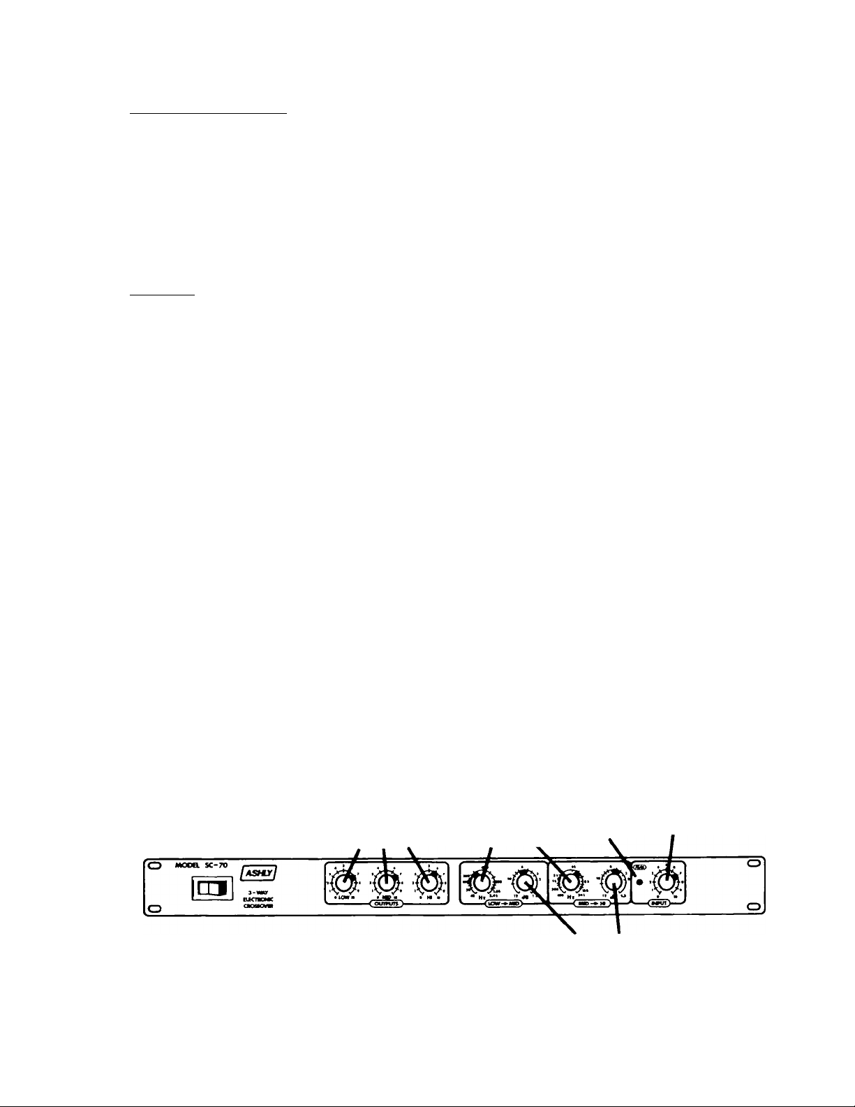
EXPLANATION OF OPERATING CONTROLS
Every Ashly crossover has the following controls: An INPUT level control, a
CROSSOVER FREQUENCY (Hz) control, a ROLLOFF (dB) control, OUTPUT level
controls, and a PEAK indicator LED.
INPUT LEVIL CONTROL
The Inpul control allows a wide range of nominal system levels to be used.
For unity aain operation, set it to 7.
Page 6

CROSSOVER FREQUENCY CONTROL
This infinitely-variable control allows you to select an appropriate crossover
point for your speakers. Turning the knob clockwise moves the crossover point
to a higher frequency, while turning it counterclockwise moves it to a lower
frequency.
Crossover frequencies are marked on standard ISO 1/3 octave center frequencies
with every octave calibrated. Calibration accuracy is very good, typically
within 1/3 octave or better. If greater accuracy than this is necessary,
measurement of the actual crossover frequency with an accurate oscillator
and/or frequency counter is suggested.
The choice of crossover frequencies depends on the type of speakers being
used, personal taste, room acoustics, and many other factors. Experiment to
see what works best for you.
CAUTION: High frequency compression drivers may be destroyed by the use of
too low a crossover frequency. Follow the driver manufacturer's
recommendations carefully.
ROLLOFF (dB) CONTROL
This control, found adjacent to the crossover frequency control, adjusts the
damping of the filter at the crossover point, affecting the response shape of
the filters. The dial calibrations (1.5, 3, 6, 10, 12) refer to the amount of
attenuation effected by the filters at the crossover frequency, i.e., a
setting of 3 means that the filter's response is "rolled off 3dB at the
crossover point", which describes Butterworth filter response.
In actual use, the rolloff control acts much like an equalizer tuned exactly
to the crossover frequency. For example, with our 12dB per octave models, a
setting of 6 on the control will give you flat response through the crossover
region. Turning the control counterclockwise will cause a dip in the response
at the crossover frequency, while turning it clockwise will cause a gentle
peak in the response. On our I8dB per octave models, a setting of 3 will
yield flat summed response.
The purpose of the control is to help offset the inaccuracies inherent in
typical loudspeaker response, thereby helping you to achieve a flat system
response. If you use a spectrum analyzer to set up your system, adjust the
rolloff control to obtain the flattest response through the crossover region
before any equalization is applied to the system. If adjusting by ear, we
recommend an initial setting of 6 for our 12dB per octave models, and a
setting of 3 for our 18dB per octave models. Then adjust from this point if
the system appears to have an excess or deficiency of response at the
crossover point.
NOTE: The rolloff control is not a "slope" control. A 12dB/octave crossover
will always have a slope of 12dB/octave regardless of the setting of
this control. Likewise, an 18dB/octave crossover will always have a
slope of 18dB/octave. The dB control only affects filter response
shape in the immediate vicinity of the crossover frequency; the
ultimate slope of the crossover is a fixed parameter.
Page 7
OUTPUT LEVEL CONTROLS
In a typical setup, power amplifiers can be run "full-on", with level control
being accomplished at the crossover. Adjust these controls for best system
balance. Note that horn and compression driver combinations are much more
efficient than cone speakers, often by 12-20dB. When cones and compression
drivers are used together, you should expect a much lower level setting for
the horns (all other factors being equal) to compensate for this difference
and obtain proper balance.
PEAK LED
Ashly crossovers feature a peak detection circuit which monitors signal levels
at several critical points in the crossover: input, filters, and outputs. The
LED will flash when signal levels of +14dBV are reached anywhere in the
crossover. Since our crossovers have a nominal 20dB of headroom referenced to
a standard operating level of OdBY (.77 Volts), a flashing LED warns you that
you are only 6dB away from clipping.
Choice of a "nominal" system operating level is really up to the operator.
You may want to run the system "hot", with the peak LED flashing frequently,
or you may want to run the system more conservatively, with the LED flashing
seldom or never.
Obviously, the hotter your nominal level, the less system headroom you will
have. For initial setup, it is recommended that you adjust your level
controls so that the LED flashes only on the loudest signal peaks, if at all.
Since peak levels are monitored at several key circuit points, the peak LED
can be used to isolate the source of any overload. If the LED flashes even
though all input and output levels are turned down, then the signal being fed
to the crossover is excessively hot. In most cases this means you should go
back and turn down your mixer. If the LED flashes when you turn the Input
level control up (with the outputs still turned down), the overload is
occurring in the filter sections, and you should back the Input level down a
bit. If the LED first flashes when you turn the output level controls up,
then the overload is occurring in the output stage, and you need to turn the
output controls down.
Output
Level
Controls
Crossover
Frequency
Controls^
Peak
Input
Level
Rolloff
Figure 2 An SC-70 3-way crossover, showing front panel controls
generic to all Ashly crossovers.
Page 8

NORMAL SETUP GUIDELINES
Speaker Placement
In order for you to obtain maximum benefit from your crossover, a correctly
assembled speaker array is a necessity. Low frequency speakers should be
grouped as closely together as possible and mid and high frequency horns
should be stacked on top of one another, not side by side. This arrangement
insures a tight vertical pattern combined with wide horizontal dispersion
free from high frequency lobing. Speakers in the array should be arranged so
the drivers and cones are all in the same plane (equal distance from the
1i stener).
Phasi ng
It is unnecessary to reverse the polarity of any of the outputs of an Ashly
crossover, as all necessary inversions have been done internally. Simply
stack your speakers and wire positive to positive, negative to negative on all
outputs.
With the multitude of different brand amplifiers and speakers used together,
phasing of all components of multi-band systems can be very confusing. Only
extreme care in the hookup of these components will insure proper phasing. It
is important not only to keep all the speakers within each band in phase with
each other but to keep all bands of the system in phase as well. If this is
not done, loss of level and pattern control at the crossover frequency will
result.
Phase of cone speakers can be checked by connecting a 1.5 Volt battery to the
speaker and observing which way the cone moves. The most common convention is
that (+) voltage on the (+) terminal moves the cone forward. A notable
exception to this convention is JBL. A {+) voltage on the red terminal of a
JBL speaker moves the cone backward. If all your speakers are the same brand,
just connect them all the same way; if not, it's best to test. Unfortunately,
compression drivers cannot be tested this way. We do know that Altec, Emilar,
and Electrovoice agree and that JBL is reversed from their standard.
Most power amplifiers have their output in-phase with the input and it is
generally not a problem to mix brands.
CONNECTIONS FOR NORMAL OPERATION
Connecting a crossover to your system is straightforward if you are using it
in its normal configuration—the output of your mixer connects to the input of
the crossover and the outputs are connected to appropriate power amplifiers as
shown in figure 3.
Page 9

Figure 3 SC-70 3-v/ay crossover showing typi'.a’
plug-in arrangement
operation.
MONO LOW OUTPUT
Ashly stereo 3-way and stereo 4-way crossovers have an addit’^anai out nr ыск
labeled MONO LOW OUT. This output represents the sum of th;:- iow riequency
outputs of channels one and two, and is typically used fo' nrivinn ' sub
woofer system. If you are using the mono low output, you '■'sy al so use the
normal low frequency outputs to drive other speaker systems; fiy or all of the
low frequency outputs may be used at any given time wthout feur of
interaction between outputs.
SPECIAL APPLICATIONS
A \Shl_' crossovers, with the exception of the mono SC-20, n;. be operated in
SO..K. configuration other than the normal mode. For example, a stereo l-ivay
crossover can also function as a mono 7-way, and a mono 3-wa> can function as
a mono 2-way. The following pages show how to connect your crossover for
these sppcial situations, with suggested front-panel settings.
NOTES:
for пог'па'
Actual crossover frequency selection will depend on specr'ic
loudspeakers and personal taste. The settings shown are for
illustration only.
For the sake of simplicity, only our 12dB per octave models are shown.
Initial setup of both 12 and 18dB/octave models will I- the same with
the exception of the rolloff (dB) control settings. You'll see that on
12 dB per octave models, we've recommended a setting ot "6" on the
rolloff control for all crossover points, and a selling of "3" for all
low-pass and high-pass cutoff frequencies. For 18(13 per octave models,
just set all rolloff controls to "3", regardless ov function.
Page 10

LOW OUTPUT
LEVEL
TO LF POWER AMP
Figure 4
The SC-20 has a feature not found on our other.crossovers:
summing inputs. When used in conjunction with a stereo
mixing console, you can use the left and right channels of
the mixer to control two submixes, and then sum these
outputs at the crossover. For mono mixers, just plug into
either of the inputs, since they are identical.
SC-22 STEREO 2-WAY USED AS
A MONO 3-WAY
TO MID POWER AMP
Figure 5
LOW OUTPUT
LEVEL
MID OUTPUT
LEVEL
K>K>
kOO
Page 11
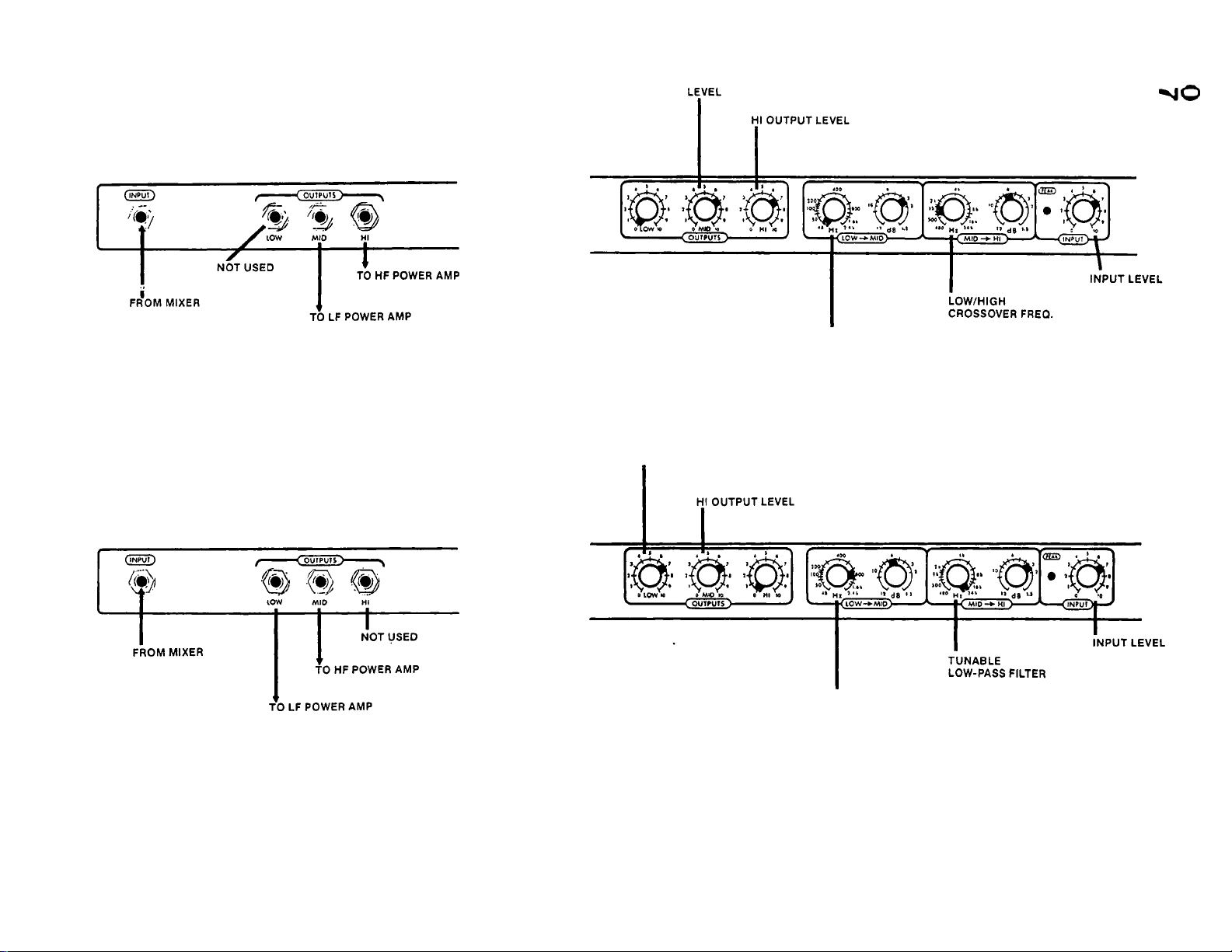
SC-70 USED AS A MONO 2-WAY
WITH TUNABLE SUBSONIC FILTER
LOW OUTPUT
TUNABLE
HIGH-PASS FILTER
Figure 6
SC-70 USED AS A MONO 2-WAY WITH
TUNABLE ULTRASONIC FILTER
SC-77 USED AS A MONO OR STEREO 2-WAY
WITH TUNABLE SUBSONIC FILTER
SC-77 USED AS A MONO OR STEREO 2-WAY
WITH TUNABLE ULTRASONIC FILTER
Figure 7
Sea Figura 6
See Figure 7
LOW OUTPUT
LEVEL
LOW/HIGH
CROSSOVER FREQ,
Page 12

SC-77 USED AS A MONO 4-WAY WITH
TUNABLE SUBSONIC FILTER
HI OUTPUT LEVEL
OVERALL
INPUT LEVEL
FROM MIXER
NOT USED
TO HF POWER AMP
Figure 8
LEVEL
CROSSOVER FREQ.
Page 13

SC-77 USED AS A MONO 5-WAY
TO MID POWER AMP
MID OUTPUT
LEVEL
00 >4
ro
SC-80 USED AS A MONO 2-WAY WITH TUNABLE
SUBSONIC AND ULTRASONIC FILTERS
NOT USED
Figure 10
NOT USED
LEVEL
Figure 11
CROSSOVER FREQ.
TUNABLE
HIGH-PASS FILTER
Page 14

SC-80 USED AS A MONO 3-WAY WITH
TUNABLE SUBSONIC FILTER
LOW OUTPUT
LEVEL
TUNABLE
HIGH-PASS FILTER
Figure 12
SC-88 USED AS A MONO OR STEREO 2-WAY WITH TUNABLE
SUBSONIC AND ULTRASONIC FILTERS
SC-88 USED AS A MONO OR STEREO 3-WAY
See Figure 12
WITH TUNABLE SUBSONIC FILTER
LOW OUTPUT LEVEL
Figure 13
See Figure 11
LOW/MID
INPUT LEVEL
SC-88 USED AS A MONO OR STEREO 3-WAY
WITH TUNABLE ULTRASONIC FILTER
Page 15
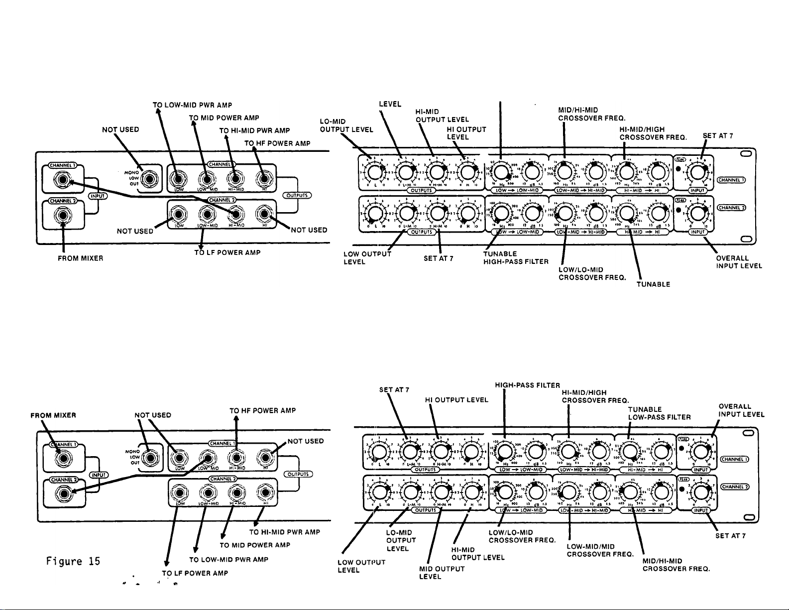
SC-88 USED AS A MONO 5-WAY WITH TUNABLE
SUBSONIC AND ULTRASONIC FILTER
MID OUTPUT
00
00
LOW-MID/MID
Figure 14 Use the above version when crossover points will be
relatively high. The lowest LOW/LO-MID crossover frequency
of 160 Hz may restrict the use of this configuration. If
lower crossover frequencies are needed, use the
configuration shown in figure 15 below.
TUNABLE
LOW-PASS FILTER
Page 16

SC-88 USED AS A MONO 6-WAY WITH
TUNABLE ULTRASONIC FILTER
TO LOW-MID PWR AMP
LO-MID
OUTPUT LEVEL
Figure 17
00
Page 17
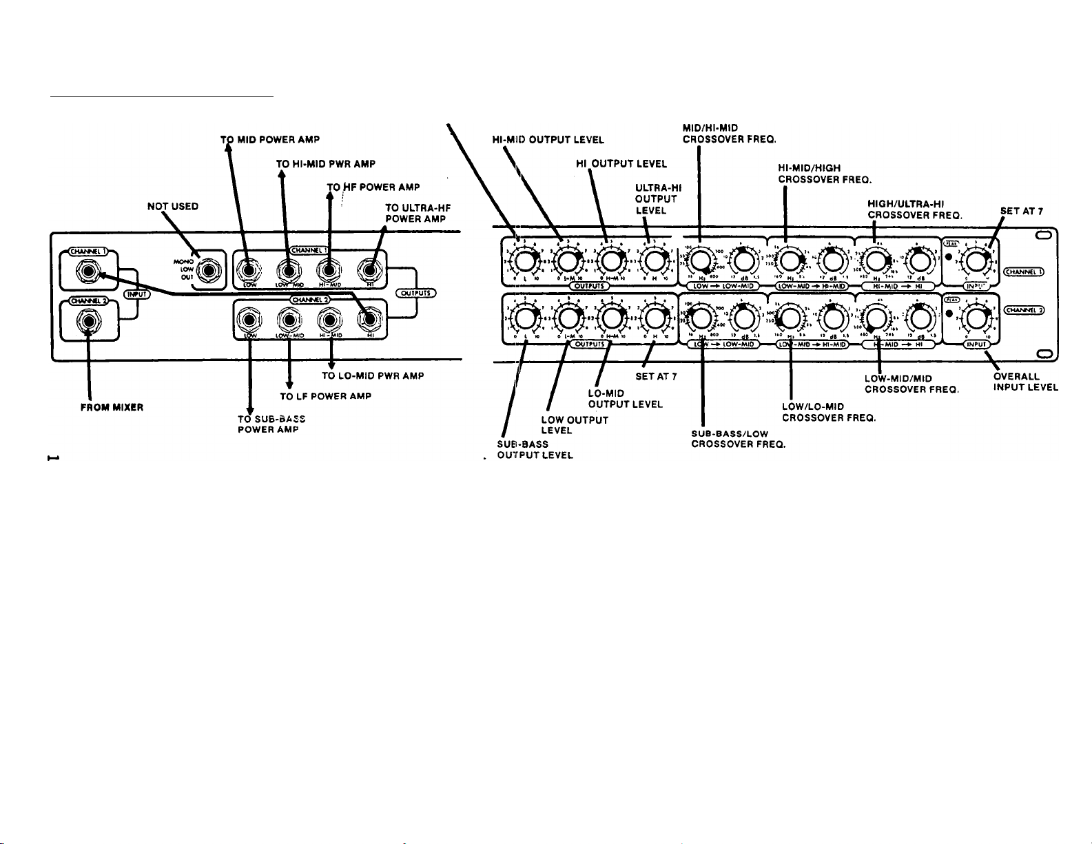
( SC-88 USED AS A MONO 7-WAY |
Oi
OQ
a
MID OUTPUT
LEVEL
Figure 18
Page 18

A CLOSER LOOK AT CROSSOVERS
IMTRODUCTION
The bulk of this instruction manual is concerned with helping a sound system
operator to get his system set up and running, and to answer the questions
"how do I plug it in" and "where should I set the front panel controls." For
those who want more information about the design and application of
crossovers, this section may be a good starting place, covering such topics as
the need for crossovers, characteristics of filters used in audio, limitations
of passive crossovers, solutions offered by biamplification, and more detailed
information regarding correct speaker alignment. The information offered here
is only an introduction to the subject, since an in-depth discussion would
certainly fill dozens of books.
As you read this, please try to always keep in mind that your crossover is
only one part of a sound system, and that the electrical performance of a
crossover, although predictable and well behaved, will almost never be
accurately reflected in the acoustic performance of a speaker array. Also,
there is no "best" approach to reproducing music through loudspeakers; there
are a variety of methods in popular use, and each method has attendant
problems and benefits which make it suitable for a particular application.
WHY USE CROSSOVERS?
The ideal speaker system would use a single small loudspeaker to reproduce the
entire audible sound spectrum at any desired power level. It would be
inexpensive, easy to hook up, and have a wel1-controlled coverage pattern that
would not vary significantly with frequency. Unfortunately, such a speaker
does not exist. Perhaps the closest approximation we have is the single
driver headphone, which can reproduce most of the audio spectrum fairly
accurately. When any larger amount of volume is required, it becomes
necessary to move greater amounts of air and larger speakers are required.
For a given loudness, reproduction of low frequencies will demand greater
changes in air pressure than high frequencies, and so will require a greater
surface area in contact with the air. A speaker capable of good low-frequency
response, then, will be relatively large. This characteristic does not favor
good high frequency response, however, since the sheer physical mass of the
large speaker inhibits the rapid back-and-forth movement required to reproduce
high frequencies. A speaker suitable for reproducing high frequencies should
be light and small. This disparity between low and high frequency
requirements gets worse as the frequency response extremes and power demanded
of a system get larger.
If one speaker cannot satisfy all requirements, then the solution must be to
use two speakers, each suited to a particular portion of the frequency
spectrum, and let each do its own job. This neatly solves one problem but
instantly creates several new ones. First of all, if the woofer and tweeter
are both wired in parallel and hooked up to a high power amplifier, there's a
good chance that the tweeter will be destroyed. The tweeter will attempt to
reproduce low frequency information fed to it, but its cone will not allow the
long back and forth excursions necessary for lower frequencies, and so the
excess pov/er being fed to the tweeter will be dissipated in its voice coil as
heat, eventually ruining it. Secondly, if the woofer and tweeter are not well
matched in terms of their sensitivity, then one range of frequencies will be
17
Page 19

too loud. Typically, high frequency speakers, particularly horn-loaded
compression drivers, are much more efficient than low frequency speakers.
Somehow, the system needs to be balanced for equal response across the audio
spectrum.
One of the inherent advantages of the "ideal" single-speaker system is that
the listener hears the entire frequency range radiating from a single "point-
source". That is, all the audio information leaves the speaker from
essentially the same place and at the same time, ensuring that the listener
hears all frequencies in the correct time and spatial relation to each other.
As soon as the single speaker approach is abandoned, this important advantage
is lost. Now, the sound is coming from two or more speakers at two different
distances from the listener, and timing and phase errors are the result. See
figure 19.
Figure 19 A listener is unlikely to be equidistant froiri two
speakers in a multi-speaker setup, resulting in
time and phase inaccuracies at the listening
1ocation.
The resulting errors are most pronounced in that range of frequencies where
both speakers are contributing equal volume. In that case, you have the same
audio information radiating from two discrete sources at the same time.
Ideally, the two resulting wavefronts should combine perfectly to reach the
listener at the same time, pushing and pulling the air in perfect
synchronization. What usually happens, however, is that the two wavefronts
reach the listener at different times and out of sync (out of phase). If the
two sound sources happen to be exactly 180® out of phase, then the listener
will experience a significant null (hole) in the sound over some range of
frequencies. If the listener then changes his position, all of the time and
phase relationships between himself and the speakers will change. These
relationships vary with frequency, too. In general, the mòre speakers that
are used in a system, the more errors that will result. This remains true in
most current professional sound systems.
Although there aren't many good solutions to this latter problem of physical
misalignment in a multi speaker system, there are, at least, solutions to the
problems of tweeter protection and sensitivity matching. By employing
frequency selective crossover networks, we can route low frequency material to
woofers and high frequency material to tweeters. This is accomplished by the
use of filters, either passive or active, which ensure that each speaker will
only "hear" that range of frequencies which it is capable of reproducing.
18
Page 20

with the frequency spectrum thus divided, it becomes possible to discard some
of the signal being sent to the tweeter, making level-matching with the woofer
a simple matter.
PASSIVE CROSSOVERS AND FULL RA^IGE SYSTEMS
The simplest type of crossover feeds the full-range amplifier output to a
crossover network with two passive filters, a low-pass and a high-pass. The
appropriate filter outputs are then connected to the woofer and tweeter, as
shown in figure 20.
■ To tweeter
To woofer
Figure 20 Passive Crossover
The advantages of the simple passive crossover are that they are simple to
hook up, they accomplish their primary job of speaker protection, and they are
cost-effective for low power applications. When built by a loudspeaker
manufacturer for inclusion in a specific speaker system, the characteristics
of the individual
can be
to
requiremencs or tne system.
However, the list of problems created by the use of passive crossovers is
fairly lengthy, particularly when used in modern high-power PA systems. First
of all, they offer no flexibility to the sound system operator. Passive
crossovers have fixed operating parameters; you can't change their crossover
frequency or filter shape. If your speaker system requirements change, you're
stuck.
Other problems have to do with the components of the passive filters
themselves, notably the inductors. Inductors are physically quite bulky, the
more so for low frequency and high power applications, making them difficult
and expensive to manufacture. Electrically, they are non-linear and subject
to saturation and ringing, and are very sensitive to external magnetic fields.
Passive crossovers are difficult to design because they are always terminated
by speakers, which present varying loads to the network. As the impedance of
a speaker varies with frequency, so will the behavior of the filter to which
it is connected. This interaction between speaker and crossover is of no help
when you're trying to achieve a certain response from your system.
Using one amplifier for the entire audio spectrum is also found to be less
than ideal. For one thing, it doesn't adequately answer the problem of
mismatched sensitivities of the woofer and tweeter. If a horn loaded
compression driver is much louder than the woofer in a passive system, the
only answer is to "throw away" some of the high frequency signal by use of an
attenuator on the crossover's high frequency output. This is certainly not
19
Page 21

efficient use of expensive amplifier power. Also, the greater the range of
frequencies an amplifier is asked to handle, the more intermodulation
distortion products you can expect to see.
All of these problems have been answered pretty well by the use of active
crossovers and mul ti-amplified systems, but of course those alternatives
present some new and unique problems as well. It remains true that, despite
their limitations, passive crossovers still have value, as evidenced by their
continued use in the majority of consumer loudspeakers and low-power PA and
recording monitor applications.
ACTIVE CROSSOVERS IN MULTI-AMPLIFIED SYSTEMS
Active crossovers evolved as a solution to the previously mentioned problems
of passive systems. In general, they are smaller, lighter, cheaper, more
flexible, more efficient, and have less distortion than passive types.
In an active system, the audio is frequency divided at line level before being
fed to the power amplifiers, as shown in figure 21 below.
MIXING CONSOLE
Output ^
Input
Low Out Hi Out
ELECTRONIC
CROSSOVER
POWER AMPLIFIER
Input (HIGHS)
POWER AMPLIFIER
• • Input (LOWS)
•To tweeter
■To woofer
Figure 21 Biampl ification
This system has a number of important advantages. The active filters in the
electronic crossover eliminate the need for inductors, thereby reducing size,
weight, cost, distortion, and hum. Active filters can easily be made tunable,
which means that the crossover can be precisely modified to fit the speaker
system at any time, a prime requirement for touring PA systems and fixed
installations as well. The filters will respond in a stable and predictable
way because they are terminated by a constant impedance within the crossover
itsel f.
Since the amplifiers are asked to work within a more restricted bandwidth, IM
distortion will be lower, and since each speaker will be driven by its own
amplifier, amp power can be distributed efficiently within each frequency
range. A given system may require a 250 watt amp for the woofer and only 40
watts for the horn.
One of the nicest benefits of an active system is an increase in apparent
loudness for a given amount of amplifier power. This is a result of the fact
20
Page 22

that low frequency amps can be overdriven without affecting the sound of the
high frequency drivers. Low frequency information requires significantly more
power from a system than high-frequency audio, and typically it is this low
frequency audio that drives a system into distortion. If only one amp is
powering a system, as in a passive or full-range setup, then important
midrange and high frequency audio will be distorted every time a deep bass
note overloads the amplifier. In a multi-amplified system, a low-frequency
amp can overload without affecting higher frequency audio in any way. But
that's not all. Fortunately, our hearing is less sensitive to distortion of
low frequencies than midrange. Large multi-amped systems are frequently
operated with what would be considered "unthinkable" levels of distortion in
the lower bass region, and yet the system may sound very clean and loud to
even a knowledgeable listener.
Some problems remain. The initial cost and complexity of a multi-amplified
system are usually greater than passive systems, but it can be reasonably
argued that the investment pays for itself in better sound per dollar.
FILTERS
Whether your crossover is a passive, high-level type, or an active, low-level
type, it employs filters to accomplish its dividing job. Therefore, a quick
look at the nature of filters seems relevant to an understanding of your
crossover.
A filter is a frequency-selective electrical network which is designed to pass
a certain range of frequencies while rejecting other frequencies. All
crossovers are made with filters, but not all filters are identical. Filters
may have a variety of characteristics and these are chosen to suit a
particular audio requirement. The most common types of filters used in
crossovers are low-pass, band-pass, and high-pass filters, supplying lowfrequency, midrange, and high-frequency outputs respectively. A low-pass
filter, as the name implies, passes low frequencies, up to a certain maximum
frequency. Above this cutoff frequency, the signal will be attenuated
(rejected) to some degree. A bandpass filter will pass a certain median band
of frequencies while attenuating any frequencies above or below those desired.
A high-pass filter performs the opposite function of the low-pass, passing all
frequencies above a certain cutoff frequency while attenuating those below.
These basic filter characteristics are usually shown in graph form as
frequency vs. amplitude, as in figure 22 below.
Figure 22 Basic filter characteristics
21
Page 23

Beyond these basic classifications of filter types, the audio designer is
concerned with the details of filter performance near and within the cutoff or
stopband. In other words, we'll assume that a filter is fairly linear within
its pass-band (for example, the flat or "plateau" portion of the low-pass
response shown in figure 22(a), but how does it behave as frequencies approach
the cutoff frequency? And, once the filter is operating in its cutoff range,
how quickly does it attenuate those undesired frequencies? Filters are not
brick walls; they will always pass frequencies outside their pass band to some
extent.
SLOPE
The rate at which a filter attenuates frequencies outside its passband is
known as the slope, and is generally expressed in decibels of change per
octave. For example, if a low-pass filter has a 12dB/octave slope, then any
frequencies outside its pass band will be reduced in volume by an additional
12dB for each octave above the cutoff frequency. If the low-pass filter has a
cutoff frequency of IkHz, then a 2kHz signal can be expected to be reduced in
volume by 12dB. Likewise, a 4kHz signal will be reduced by 24dB, and an 8kHz
signal will be 36dB down.
The slope of a filter is a function of the number of frequency-reactive
components within the filter. Avery gentle slope, such as would be found in
a 6dB/octave passive filter, might contain only one such component in the form
of a capacitor connected from the audio to ground, as shown in figure 23. A
capacitor passes high frequencies very well while blocking low frequencies.
Therefore, any high frequency audio will be shorted to ground and not heard at
the output. This type of filter is called a first-order filter. It is not
terribly useful for crossovers because of its gentle slope; it won't provide
much protection to high-frequency drivers when used in its high-pass version.
(a)
(b)
Figure 23 Passive RC first order low-pass filter and response.
High frequency loudspeakers will be better protected by a steeper slope, which
can be obtained with a second-order filter such as the passive LC second-order
filter shown in figure 24. Here, there are two frequency-reactive components:
a capacitor (C), which easily passes high frequencies, and an inductor (L),
which easily passes low frequencies. The slope will be 12dB/octave.
22
Page 24

Passive LC 2nd order lowpass filter and response.
RESPOIJSE SHAPE
The performance of the filter in the immediate vicinity of the cutoff
frequency is important to consider, as it will affect the way a filter sounds
and the way in which its response combines with another filter in a multiplefilter system. Some filters begin to attenuate well before the cutoff
frequency, while some remain essentially flat up to cutoff before abruptly
beginning to attenuate. Some filters even exhibit an increase in amplitude as
they approach the cutoff ooint, and then quickly reverse themselves and begin
to attenuate.
These various response characteristics each has an application, and some of
the most common ones have been given names, including Butterworth, Bessel,
Chebyshev, Cauer, and Elliptical. The Butterworth response shape is very
popular in conventional crossovers. Also called a "maximally flat" response,
it stays quite flat within the pass-band and then falls off with a very linear
slope. In actuality, it does not remain perfectly flat right up to the cutoff
frequency, but begins to roll off a little earlier, so that the response is
down 3dB at the cutoff frequency. A response plot of a low-pass 12dB/octave
Butterworth filter is shown in figure 25.
Figure 25 Butterworth response.
23
Page 25

RESONANCE AND DAf^PING
To understand the response characteristic of a particular filter, it is
necessary to consider the factors of resonance and damping. This may be best
accomplished by considering examples of resonance in everyday physical objects
and then seeing equivalent effects in our filter circuits.
If you pluck a guitar string, it will vibrate back and forth at a certain
frequency, called its resonant frequency. The vibrations will not go on
i ndef i ni tely, since some part of your initial energy will be 1 ost wi th each
excursion. The energy will be dissipated by mechanical and acoustical
friction, and also through the energy of the radiated sound. Eventually, the
string will come to a halt. The process of energy absorption which slows and
stops the string is called damping. Heavy damping, which would result if you
touched the string with your finger, stifles the sound quickly, while a freely
moving string would allow the tone to continue for a long period of time.
A loudspeaker system also has its own resonant characteristics, affected by
the speaker itself, the cabinet it is mounted in, the damping material in the
cabinet and even the room in which the speaker is located. When such a system
is asked to reproduce frequencies which approach or coincide with its own
resonant frequency, it begins to behave in a non-linear fashion. It offers
much less resistance (impedance) to the stimulus, and as a result its output
will be greater than at other frequencies even though the magnitude of the
stimulus remained unchanged. The loudspeaker will be "boomy" or "peaky" at
that frequency. However, if you stuff large amounts of absorbent fiberglass
into the cabinet, that boominess will probably be attenuated somewhat, owing
to the acoustical damping effect of the fiberglass on the cabinet's resonance.
This example of mechanical damping has an electrical equivalent in the filters
in your crossover. That is, a filter has a resonant frequency of its own, and
can actually have a tendency to oscillate if so designed. On the other hand,
the filter can be designed so that its resonance is "heavily damped," thus
stifling any tendency to oscillate. This characteristic will be seen to be a
very important factor in the summed response and overall sound of a crossover.
Let's take another look at a simple passive LC second-order low-pass filter,
shown again in figure 26 below.
(a)
Figure 26.
24
Page 26

The filter of figure 26(a) is resonant at the cutoff frequency, and that
frequency is proportional to the product of the inductor and capacitor values,
L and C. We can control not only the product of the inductor and the
capacitor, but their ratio as well. For example, if the capacitor is made
very large and the inductor very small, the load resistor, R|_ will not
significantly load the LC circuit. The circuit then behaves as a seriesresonant circuit with relatively low losses, and will in fact be on the verge
of oscillation. For frequencies near resonance, the circuit will exhibit
voltage gain or peaking, much like our resonant speaker cabinet example. A
common name for this type of circuit behavior is underdamped response, and its
response curve is plotted in figure 25(b).
By balancing the ratio of R, C, and L in the same second-order circuit, we can
produce a very flat response curve with no peaking at all near the cutoff
frequency, f^-. This type of response is known as a critically damped curve.
You may also hear it referred to as a maximally flat or Butterworth response.
To go a bi-t further, if we use a very small capacitor and a very large
inductor, the load resistor dominates and gives a very droopy, highly damped,
response as shown by the lower curve in figure 26(b).
Realize that all three of these response patterns (over, under, and critically
damped) start out at unity gain and end up rolling off at the same ultimate
slope, in this case 12dB/octave. Also, the cutoff frequency remains the same.
Setting the damping by changing the inductor-capacitor ratio determines only
the shape of the response curve near the cutoff frequency.
You might also hear damping referred to as "Q". Actually, Q is simply the
inverse of damping. An underdamped, peaky response has a very high Q, while
an overdamped response has a Q which tends toward zero. A critically damped
filter has a Q of 0.5.
ACTIVE FILTERS
The filter examples given so far have used passive types for purposes of
illustration. These were the first filters used for audio, and although their
performance can be very good under some conditions, they have been almost
universally replaced in modern electronic crossovers by active filters. By
combining resistors and capacitors with IC op-amps, we can accurately simulate
the performance of traditional inductance-capacitance filters.
The advantages of active filters are many. They are inexpensive, lightweight,
and compact, the more so at very low frequencies, where inductors wou'e. be
large, heavy, and expensive. They are easily tuned over a wide ran-e of
frequencies, they are largely unaffected by external loading, and they don't
require exotic shielding to protect them from magnetically induced hum.
Having now touched upon some basic filter characteristics, we can get back to
the main subject of discussion, namely loudspeaker crossover networks.
HOW CROSSOVERS ARE BUILT
The majority of the commercially available electronic crossovers are made by
simply combining an active low-pass filter and an active high-pass filter.
Usually, the response shape of each filter is Butterworth, and a single front
25
Page 27
panel control tunes the cutoff frequency of both filters simultaneously. This
type of crossover is illustrated in figure 27.
dS
♦ 6 - -
frequency‘tuned
with single front'
panel control.
Figure 27.
A typical Butterworth-response 2-way
electronic crossover, made by
combining a low-pass and high-pass
filter. Note that the crossover
frequency is at the "3dB-down" point
of each filter. This approach to
crossover design works fairly well,
but the'response shape of each filter
is fixed, and therefore there can be
no control over the summed response
of the network at the crossover
■20K
Frequency (Hz)
*«i t
frequency. The summed response will
.show,a +3dB "bump" at the crossover
frequency.
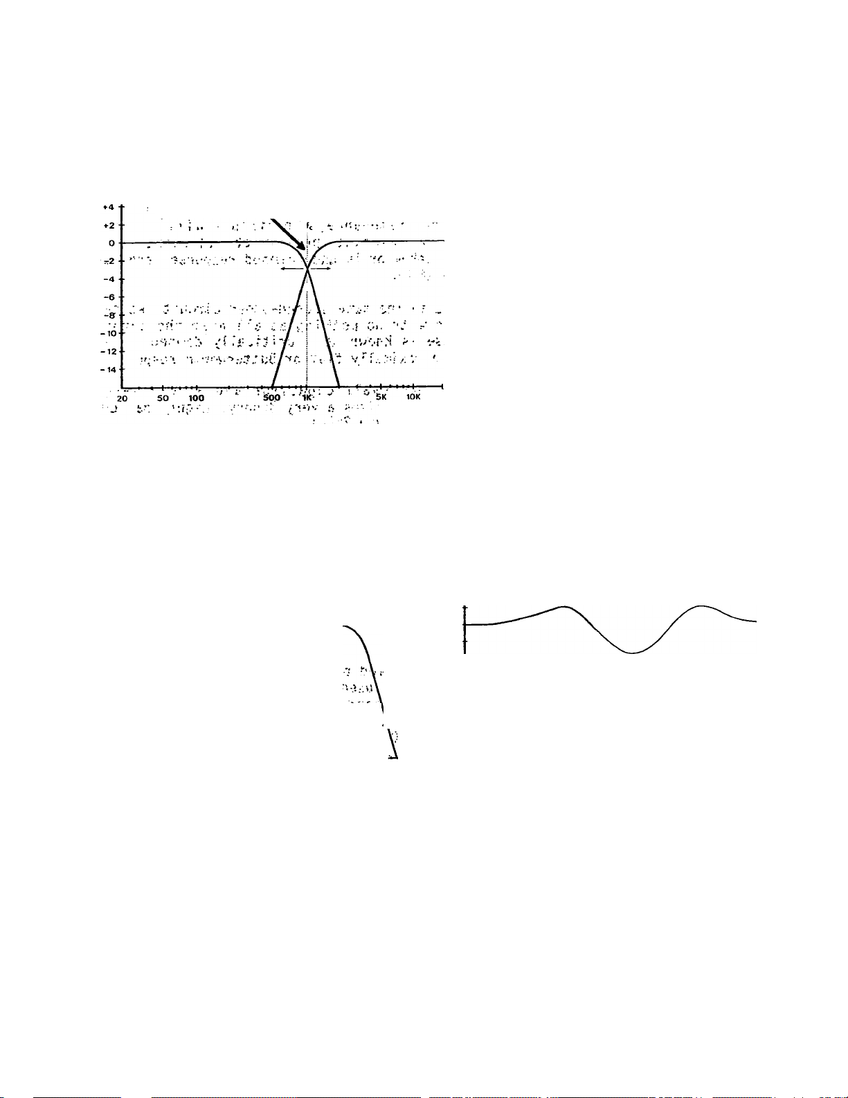
, Another popular approach.uses, the same two overlapped filters just shown, but
gives the operator independent, control of. each filter's cutoff frequency, ie.,
.two front-panel,-frequency adjustments ..for each .crossover point. This provides
an, opportunity to either, overlap ..the two pas,s, bands or pull them apart. The
result may not be quite what-you had in mind, as illustrated in figure 28.
dB
♦6- •
t4
+2
0
-2
-4
-6‘
-8
-to
-12
-M
50
>0 500
. V * r “■ )S J?. ^ I'
-Ci
IK
5K 10K 20K
i- Ffeqwcn<y,(Hi)
dB
■ li. •
' »4*
»2
0
-2
-4
'^8
1 -^0
• 12
• -14
Mfs-
5K 10K 20K
Frequcn<y (Hz)
(b)
;r. ^
iU\ i i':;;. *
Figure' 28.
V 0 ^
Here,' the i bw-pass and'high-pass"' ' fh e two filters of (a), when
; fil ters, are shown, ovej;lapping by ..two, j electronical ly summed, will combine
octavq^, .in, each‘,dTr^^^^ the ' to giye. you a very uneven response
crossover'point'.' Tou'niight'logically ' curve with two peaks near the
expect a nice even boost in summed individual cutoff frequencies, and a
response throughout this overlap dip in the crossover region,
regipp., bu.t , .that's no,t...what. you'.l?.
actuai ly ge^^tV.
Athfy'electronic crossovers, uni ike the two'examples just given, do not use
25
Page 28

two fixed-response filters to form a crossover. Instead, a single statevariable filter provides both low-pass and high-pass outputs, and a single
control adjusts the crossover frequency. Because the state-variable filter
allows complete control over all filter parameters, it is possible to tune the
response shape of the filter for the best possible summed response. As you'll
recall, response shape is determined by filter damping, and so all Ashly
crossovers feature a damping control, labeled dB, at each crossover point.
Figure 29
This state-variable filter,
representative of the filters
used in Ashly SC-series
crossovers, is an analog
computer realization of a
second-order (two pole or two
integrator) filter system.
HP OUT IP OUT
From the standpoint .of the ..sound system operator,. the Ashly filter approach
combines the one-knob frequency control convenience of the first crossover
example (fig. 27) with the summed response flexibility of the second crossover
example (fig. 28). In contrast to the bumpy response of fig. 28, Ashly cross
overs exhibit the smooth and predictable summed response curves shown below.
(a)
Figure 30. (b)
This graph plots the high-pass and
low-pass outputs of the Ashly
12dB/octave filter for 4 different
settings of the dB control. The line
marked "3" shows Butterworth
response, and is obtained by setting
the control to 3. The other curves
show the response shapes obtained by
over and underdamping the filter.
This graph shows
curves of (a)
electronically
Butterworth curves
3dB peak, but other responses are
easily obtained; for a flat summed
response, set the dB control to 6.
(12dB per octave models only)
27
how the response
combine when
summed. The
sum with a gentle
Page 29
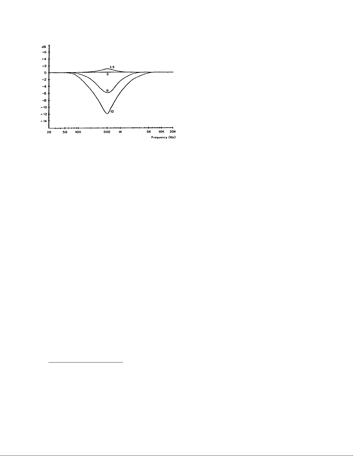
Figure 31
The summed amplitude response of
the Ashly 18dB per octave
crossovers. For these models, flat
summing is achieved by setting the
dB control to 3.
Another nice feature of the state-variable filter is that once you set the
damping for a particular response, you don't need to re-adjust it for new
crossover frequencies. For example, if you own an Ashly 12dB per octave
crossover and have set the damping (dB) control to 6 for flat summing, you can
then set the crossover frequency anywhere you want and the outputs will always
sum flat. This is not true of other crossover designs.
At this point, you might ask why we don't simply tune the filter responses for
flat summing and remove the rolloff (dB) control from the front panel
altogether. After all, who wants less than a perfectly flat response? To
answer that question, you have to put everything back into perspective and
remember that the crossover is not goi.ng to be connected to a resistive
summing network. In the real world, you'll be hooking the crossover up to
amplifiers which will in turn be connected to speakers which will in turn be
acoustically coupled to the air and to each other. Loudspeaker reponse is not
likely to be ruler flat at the crossover frequency; instead, there will likely
be a hot spot or a deficiency in response due to the imperfect nature of the
speakers. When that happens, all those careful calculations about flat
summing fall flat on their face. All of the sudden, you find that you need an
equalizer right at the crossover point, and with an Ashly crossover, you've
already got it. Take another look at those response curves of figures 30 S 31
above; in practive, being able to modify the damping of the filter in your
crossover is just like having an equalizer tuned precisely to your chosen
crossover frequency. The Ashly SC series crossovers give you the best of both
worlds: electrically flat summing to satisfy the lab technician, and a choice
of response shapes to help you approach acoustically flat summing where it
really counts—in a real-life loudspeaker system.
CROSSOVER EVALUATIOM
A popular and convenient method of evaluating a particular crossover is to
look at summed amplitude response, which can be accomplished by simply wiring
all the outputs of the crossover together in parallel through an appropriate
resistive network. The theory behind this sort of examination is that if you
add all the outputs together, the sum of the individual pass-bands should
equal the input signal. That is, the crossover should be capable of a flat
summed response. It is often said, incorrectly, that 12dB per octave
23
Page 30

crossovers are incapable of flat summed response, while 18dB per octave types
do sum flat. The two determining factors in summed response, response shape
and phase relationship between fiIters, are frequently ignored or
mi sunderstood.
PHASE SHIFT
When audio is passed through a filter, there will be a shift in the phase of
the signal. This is true of both active and passive filters. For example, in
a simple second-order (12dB/octave) crossover network, the low-pass output
will lag the high pass output by 180°. That means that there will be an
actual time difference in the movement of woofer and tweeter at the crossover
frequency; as the tweeter moves forward, the woofer will be moving backwards,
since the woofer will always be 1/2 wavelength behind the tweeter. If the two
drivers are of equal efficiency at the crossover frequency, their simultaneous
pushing and pulling will cancel each other out, and the result will be an
audible notch at the crossover frequency. This is even more obvious when thë
two filters are electrically summed--there will be a very deep notch in the
summed response curve where the two filters meet and cancel each other out.
Fortunately, there is an easy solution.
When two signals are exactly 180° out of phase, it is a simple matter to
invert the polarity of one output, thus eliminating the notch effect. That
explains why you'll often hear people say the the outputs of a 12dB per octave
crossover should be wired out of phase. This is one way of getting around the
phase error inherent in these crossovers. However, this would be a mistake
with an Ashly crossover; we have already performed all necessary phase
inversions internally in our crossovers so that the user can simply wire
everything in phase without having to stop and think about which outputs to
invert and which ones not to invert. Unfortunately, this is notan agreedupon standard among crossover manufacturers, and so there is confusion on this
poi nt.
18dB per octave crossovers also have filter phase shifts, but unlike the
second-order crossovers, their outputs come out 90° out of phase, a difference
of 1/4 wavelength. When electrically or acoustically summed, these outputs
will not produce the notches associated with second-order crossovers. Phase
inversion and polarity swapping are not necessary.
RESPONSE SHAPE
Another source of confusion in summed amplitude response testing is response
shape of the individual filters. You'll hear it said that, even when wired
in-phase, 12dB per octave crossovers won't sum flat. It is true that 12dB per
octave Butterworth shape filters won't sum flat, and this is the source of the
unfortunate generalization. However, if the filters are more highly damped,
then flat summing is certainly possible. This was illustrated in figure 30.
CHOICE OF SLOPE
Once it is realized that the slope of a crossover doesn't necessarily have
anything to do with summed amplitude response, we can proceed to choose a
crossover slope based on more important criteria. The choice of a particular
slope is largely subjective; some people like the "sound" of an 18dB per
octave crossover, while others might feel that its steep cutoff characteristic
29
Page 31

makes it sound harsh. One thing that is clear, though, is that a steeper
slope will afford more protection to high frequency drivers than a gentle
rolloff. For the majority of audio applications, a 12dB per octave crossover
will be found to be perfectly adequate. Where extra protection is deemed
necessary, choose the 18dB per octave type.
SUNMED PHASE RESPONSE
Nearly all crossovers introduce phase shifts that vary as a function of
frequency, but this is not considered to be a problem since our ears don't
seem to be very sensitive to phase shift. Just to set up a suitable A/B
comparison to test the audibility of phase shift would be quite a feat, since
it would require near-perfect speakers and source material. After all, phase
shifts are introduced virtually everywhere in an audio system; microphones,
transformers, equalizers of all kinds, effects units, crossovers and speakers
all contribute significant amounts of phase error. In short, crossover phase
shift effects are not considered to be an important factor in the accuracy of
a sound system.
SETTING UP YOUR SYSTEM FOR ACCURATE REPRODUCTION
In order to realize the best possible performance from your sound system, it
is desirable to strive for the best possible phase relationships between
separate drivers. Since it is impossible to have all of your speakers radiate
their energy from the same point in space, your only option is try to keep
their acoustical centers coherent in at least one plane, i.e., try to stack
the speakers with the drivers centered in one vertical line. This will
projection pattern of the systi
minimize phase cancellations and improve
tMC
Notice we aren't saying you'll achieve perfect phase correlation in your
system, because you won't. There are simply too many variables in a multi
speaker system.
For example, we've recommended that you stack your speakers in one vertical
plane, but what if you've got 2, 4, or 6 bass bottoms per side, all
reproducing the same frequency? In that case, you've got wavefronts radiating
from physically separate points in both the vertical and horizontal plane,
which means that the system's polar pattern and amplitude response will be
subject to the way those wavefronts add and subtract as they recombine.
Then, there's the knotty problem of determining where the wavefront actually
emanates from in a real speaker. Does it radiate from the diaphram in the
driver, and should that be considered the acoustical source for alignment
purposes? Or, if that driver is connected to an exponential horn, should we
consider the mouth of the horn the correct alignment point? What's the phase
relationship between the mouth of the horn and the diaphram? What about a 15
inch woofer flush-mounted to a ported enclosure? Or a dual 15 inch folded "W"
cabinet—where is its "acoustical center"? As you can see, there's room for
error in a multi-speaker system. Generally, the more complex the system, the
more difficult the phasing question.
All of this is not to say that contemporary sound systems don't work or sound
good—they can and do. Just keep in mind that there are physical limitations
in a real sound system that make perfect phase alignment nearly impossible.
Again, if you'11 try to keep the system al igned in at least one piane, you'l 1
probably be doing the best you can.
30
Page 32

SUMMARY
The ultimate goal of a sound system is the faithful reproduction of music and
speech without additional coloration. Having departed from the ideal single
speaker approch, we now have a number of variables which will influence the
overall sound, including the crossover, amplifiers, time and phase errors
which result from having spatially displaced drivers, and the individual
personalities of various kinds of speakers reproducing overlapping
frequencies; an aluminum diaphram compression driver coupled to a fiberglass
horn will sound different than a paper cone woofer, even though both may be
reproducing the same frequency. Also, each speaker can be expected to have
significant variations in its frequency response, even within its flattest
range. The summed acoustic response of a loudspeaker system therefore becomes
a function of the crossover, the amplifiers, the loudspeakers, and the room in
which it's all used. Of these, the loudspeakers and room acoustics remain, by
far, the greatest sources of error in typical installations.
We have given rough guidelines for setting up multiple loudspeakers, but
sometimes even the most minimal attempts at speaker alignment will be
difficult to implement. For example, in a touring sound system, first
consideration may have to be given to setting up the speaker stack in such a
way that it doesn't fall over or get in the way of a lighting truss, rather
than to optimum phase alignment. It's worthwhile to keep a sense of humor
when theorizing about the "perfect" speaker installation; the variables can be
overwhelini ng.
There is no "best" approach to sound reproduction, since every application
demands something unique from a system. A two-way passive system can sound
great, and a 7-way multiamplified system can also sound great. It's probably
true, however, that an unskilled operator can create more havoc with a complex
system than with a simple one, so the value of simplicity should not be
di smissed.
Just as there is no single best approach to sound reinforcement, there is no
single best crossover characteristic which is best for all applications. A
parametric-type crossover, offering control of crossover frequency, filter
damping, and output levels, ensures enough flexibility to meet changing system
requi rements.
31
Page 33

ACTIVE
Electronic circuits which use devices such as transistors and integrated
circuits, and which are capable of voltage and power gain as well as
loss. Circuits using only resistors, capacitors, transformers, etc., are
referred to as passive.
AMPLITUDE
The voltage level of a signal. May be measured in volts or decibels.
Generally corresponds to the volume or intensity of an audio signal.
BALANCED
A 3-wire circuit arrangement in which two conductors are designated as
signal lines (+ and -), and the third is a shield and chassis ground. The
signal lines are of opposite polarity at any given moment, and are of
equal potential with respect to ground. Balanced input amplifiers are
used on all Ashly SC series products to improve hum and noise rejection.
Jumpering signal minus (-) to ground provides an unbalanced input.
BUTTERWORTH
The name of a particular filter response shape. The response is
essentially "flat" within the pass-band, is 3dB down at the cutoff
frequency, and continues to attenuate at a constant slope. Also called a
"maximally flat" or "critically damped" filter shape, it is very popular
for crossovers and shelving filters.
DEFINITION OF TERMS AS USED IN THIS MANUAL
CENTER FREQUENCY
The frequency (or pitch) at which a filter is most effective. In a
parametric equalizer, it refers to the frequency where a particular
boost/cut control has maximum effect.
DAMPING
A force which opposes the tendency of a system to oscillate.
dB
A unit by which audio levels can be COMPARED. Often thoroughly
misunderstood are the concepts that decibels represent the level of a
signal compared to some reference level (15 dB cut means a certain level
less than a previous level — the absolute level of the signal need not
be known), and that decibels are a logarithmic unit.
Some handy numbers to remember when dealing with decibels;
+3 dB = Double Power
+6 dB = Double Amplitude, Quadruple Power
+ 10 dB = lOX Power
+20 dB = lOX Amplitude, lOOX Power
dBm
A unit of measurement in decibels where 0 dBm = a power level of 1
milliwatt into a 600 ohm load. Originally defined by the telephone
company to measure line levels.
32
Page 34

dBV
Decibel Volts, an update of the dBm definition where 0 dBV = the same
voltage level as 0 dBm, but with no regard to power or impedance. 0 c"'V =
0.778 Volts. This unit is much more appropriate for modern i.^dio
equipment with high impedance inputs and low impedance outputs.
DISTORTION
Generally refers to ANY modification of an aulio signal whicn prodjces
new frequencies which were not in the original. Examples are harmnic
distortion, where a circuit adds overtones to a fundamental signal, and
intermodulation or IM distortion, where two frequencies beat together to
produc“ sum and difference frequencies.
FEEDBACK
Gene- ally '-e'-ers to any orocess where an output is in some form routed
back CO an input to establish a loop. Negative feedback tends to be be
self stabilizing, while positive feedback causes instability.
FILTER
A cii.uit «lesigned to pass some frequencies, but not others. There are
three general categories of filters; High-pass, band-pass, and low-pass.
The -'igh-pass filter passes frequencies above a certain limit, the low-
pass )asses frequencies below a limit, and the band-pass passes one group
of t. *^queru: les without passing those above or below. Our equalizer uses
band tass filters, crossovers use high and low-pass filters.
FREQUENCE
The
eye ’ t
epetition rate of a waveform. Frequency is measured in Hertz. One
per second (cps) is one He
seal e
FREQUENCV -(ESPONSE
Refers to relative gain ano loss at various frequencies across the audio
band. May be illustrated oy a graph called a frequency response plot,
usual' / graphing decibels vs. Hertz or octaves.
HERTZ (hz.
The iitiit of frequency measurement,
this ^.xplains it perfectlyl
HEADROOM
Refers to the increase in level above normal operating level that can be
obtai'ied without clipping. Usually expressed in dB.
IMPEDANCi
Essen'lally the AC equivalent of resistance. It describes the drive
capability of an output, or the amount of drive required for an input at
any given signal level.
KHz
Kilonertz. 1,000 Hertz.
the higher its frequency.
/ U T \
\ I I / .
higher a note on a niusii
(Formerly called Cycles-per-Second:
LEVEL
The magnitude of a signal, expressed in decibels or volts.
33
Page 35

LINE LEVEL
Meaning "somewhere around OdBV" as opposed to MIC level of around -40dBV.
OCTAVE
A logarithmic unit to compare frequencies,
+1 Octave means double
frequency, -1 Octave means half frequency.
OHM
The unit of electrical resistance or impedance.
ORDER
A term describing the slope of a filter. A first order filter will have
a slope of 6dB/octave, second-order will be 12dB/octve, third-order will
be 18dB/octave, fourth-order will be 24dB/octave, and so on. Higher
order filters are typically made by cascading lower-order filter
sections.
PHASE
Describes how well two signals are in step. In-phase means that positive
and negative peaks in two signals occur together, while out-of-phase
means they do not occur together. Variations in signal timing as well as
polarity can make two signals in or out of phase, or anywhere in between.
Phase is usually measured in degrees where 0 degrees is in-phase, 180
degrees is out-of-phase, and 90 degrees is in between (sometimes called
quadrature).
PREAMPLIFIER
The first stage of amplification, designed to boost very low level
signals to line level.
A measurement describing the sharpness or broadness of a filter.
RESONANCE
The tendency of an electrical or mechanical system to vibrate (or
oscillate) at a certain frequency.
SHELVING
Describes an equalization action where all frequencies above or below a
particular frequency are boost or cut.
SLOPE
In a filter or equalizer, a description of the rate of boost or
attenuation. Normally specified in dB/octave (6, 12, 18, or 24dB/octave
slopes are most common). The steeper the slope, the higher the "Q" in a
filter.
TRANSIENT
A sudden burst of energy in an audio signal, such as a breath blast in a
microphone, the sound of a snare drum, or a deep scratch in a record.
Transients frequently reach peak levels of 10 to 30 dB above standard
operating level, and may cause distortion or even damage to equipment.
34
Page 36

UNITY GAIN
Output level = Input level.
WIRING, PHONE PLUG AND XLR
A stereo phone plug is wired + to the tip, - to the ring, and shield to
the sleeve. For a mono phone plug, combine - and shield, and connect both
to the sleeve.
An XLR (3 Pin) connector is wired + to pin 3, - to pin 2, and shield to
pin i.
Mono Phone Plug:
(for unbalanced
inputs and outputs)
Stereo Phone Plug:
(for balanced in
puts and outputs)
XLR Type Connector:
(Male Shown)
Sleeve
35
Page 37

FREQUENTLY ASKED QUESTIONS ABOUT ASHLY CROSSOVERS
Is the "dB" control a slope control?
If I set it at 6, will my crossover
have a slope of 6dB per octave?
A; No, this control has no effect on the ultimate slope of the crossover.
Slope is a fixed parameter; i.e. a 12dB per octave model will always have
an ultimate slope of 12dB per octave, regardless of front panel control
settings. The rolloff (dB) control actually affects the damping of the
filter circuit in the vicinity of the crossover frequency. In practice,
this control acts much like an equalizer tuned to the crossover frequency,
with clockwise rotation of the control producing a boost in the summed
response at the crossover point, and a counterclockwise rotation producing
a dip in the summed response. See pages 5 and 27.
Q: Where should I set the "dB" control?
A: We recommend an initial setting of 6 for our 12dB per octave models and a
setting of 3 for our 18dB per octave models. Then, tune for flattest
response or best sound.
Q: Are Ashly crossovers capable of flat summed amplitude response?
A: Yes. In addition, other summed response shapes are available via the "dB"
control, helping to compensate for uneven speaker response.
Q; Can my crossover be connected to long snakes and drive low impedance
1 oads?
A: Yes. The output stage is designed to tolerate low impedance and reactive
loads without degrading performance, and provides good immunity from RF
and other common-mode noise.
Q: What does a flashing peak light indicate?
A: You are either very close to or already in clipping. Our peak circuit
monitors signal levels at several key points in the audio chain. See
page 6.
Q: How should I choose my crossover frequencies?
A: Follow speaker manufacturers recommendations for lowest and highest
crossover points. Too low of a crossover frequency may damage some high-
frequency drivers. Within a given safe range of crossover frequencies,
the actual choice of the crossover point is largely a matter of personal
taste and sunnied system response.
Q: Should I wire any of the crossover outputs out of phase with each other?
A: No. All necessary phase inversions are done internally in Ashly
crossovers.
36
Page 38

TROUBLE SHOOTING TIPS
NO OUTPUT
Check AC power - is the pilot light on? Check in/out connections, are
they reversed? Are you sure you have an input signal?
PEAK LIGHT FLASHES OR STAYS ON ALL THE TIME
If the LED continues to flash when all of the crossover level control s
are turned down all the way, it indicates that the crossover is being fed
excessively hot levels from a previous piece of equipment. Turn down
your mixer.' See page 6.
DISTORTED SOUND
Is the peak light flashing? If it is, an overload is occuring within the
crossover, and may also be occurring in other parts of the system. If
the peak light is not flashing, the distortion is occurring somewhere in
the system prior to the crossover.
EXCESSIVE HUM OR NOISE
Hum will usually be caused by a "ground loop" between components. Try
using the suggested balanced input and output hook-ups if the other
pieces of equipment used in conjunction with your equalizer have balanced
inputs and outputs. Noise can be caused by insufficient drive signal.
NOTE:
UN-SHIELDED CABLES, IMPROPERLY WIRED CONNECTIONS, AND CABLE WITH BROKEN
STRANDS (SHORTS ETC.) ARE THE MOST COMMON PROBLEMS. MAKE SURE YOU USE
GOOD QUALITY CABLE.
WHEN IN DOUBT, GET IN TOUCH WITH YOUR ASHLY DEALER, OR CALL THE FACTORY
DIRECT - (800)828-6308. In New York State dial (716)544-5191.
37
Page 39
SPECIFICATIONS
INPUr GAIN - oo • -10d8
ROLLOFF: 1.5dBV-12dB (crossover point
OUTPUT GAIN - oo - +20dB
INPUT IMPEDANCE 10k ii txjlonced bridging
OUTPUT IMPEDANCE 50 unbalanced-terminote
depth)
with 600 il or more
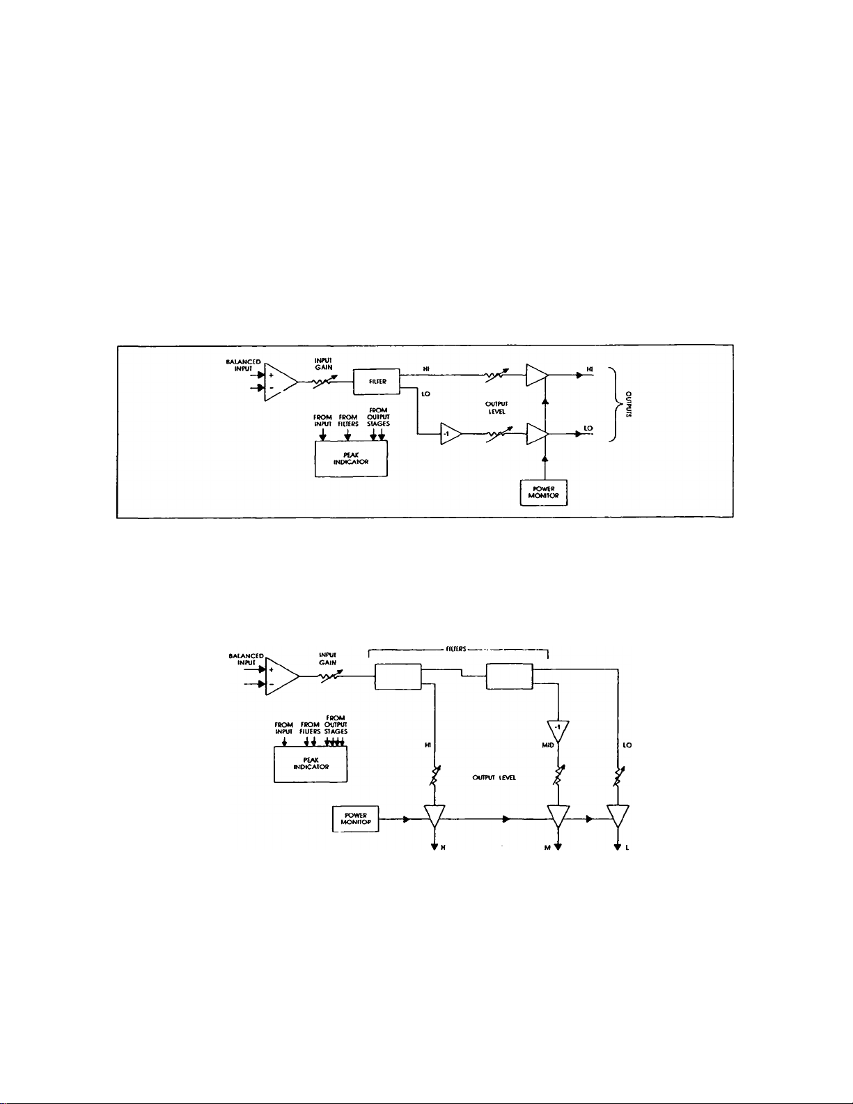
BLOCK DIAGRAMS
MAX. IN-OUT LEVEL +20dBV
FREQUENCY
RESPONSE +.5dB 20Hz-20kHz (within
DISTORTION < .05% THD, +10dBV
HUM AND NOISE -90dBV
POWER 120 VAC. 50-60HZ, 5W.
passband)
20Hz-20kHz
Figure 31 Block diagram of Ashly 2-way crossovers
Figure 32 Block diagram of Ashly 3-way 12dB/octave crossovers
38
Page 40

Figure 33 Block diagram of Ashly 4-way 12dB/octave crossovers
Figure 34 Block diagram of Ashly 3-way 18dB/octave crossovers
Figure 35 Block diagram of Ashly 4-way 18dB/octave crossovers
39
 Loading...