

Page 1
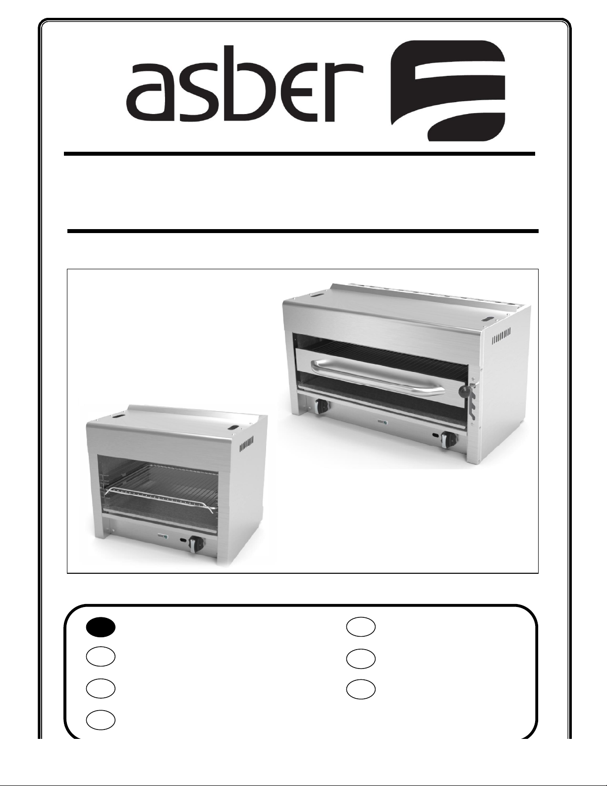
SALAMANDER/CHEESE MELTER
Manual instructions
Manueltalimatları
Manual de instrucciones
Manuel d’instructions
Bedienungshinweise
Manual do instruções
Ręczny
Obsługaikonserwacja
ES EN
DE TK
FR PT
PL
Manual Instructions
AESB-24, AESB-36, AECM-24, AECM-36,
Installation and Operation
Uso y mantenimiento
Installation und Betrieb
Kurulum ve Çalıştırma
Installation et fonctionnement
Instalação e Operação
Page 2

asberprofessional.com
DOCUMENTCODE:
INDEX
ENGLISH
MACHINE INTRODUCTION ................................................................................................................................ 1
1.1 INTRODUCTION TO MACHINE& MODELS ........................................................................................... 1
1.2 IMPORTANT SAFETY INFORMATION .................................................................................................. 1
1.3 SPECIFICATION CHART ....................................................................................................................... 1
INSTALLATION .................................................................................................................................................. 2
2.1 Transport, handling, unpacking, location ........................................................................................... 2
2.2 Manufacturer’s identification label description ................................................................................. 2
2.3 Installation and assembly .................................................................................................................. 3
2.3.1 UNCRATING ............................................................................................................................... 3
2.3.2 INSTALLATION ........................................................................................................................... 3
2.4 Gas Connections ................................................................................................................................ 4
2.4.1 MANUAL SHUT OFF VALVE ......................................................................................................... 5
2.4.2 PRESSURE REGULATOR .............................................................................................................. 5
2.4.3 THIS APPLIANCE IS EQUIPPED FOR NATURAL GAS. ..................................................................... 5
2.4.4 PRESSURE REGULATOR CONVERSION ........................................................................................ 6
2.5 Location ............................................................................................................................................ 6
2.6 CLEARANCES ..................................................................................................................................... 7
2.1 AIR SUPPLY & VENTILATION............................................................................................................... 7
OPERATION ...................................................................................................................................................... 8
3.1 General information. ......................................................................................................................... 8
3.2 ................................................................................................................................................................ 8
3.3 LIGHTING INSTRUCTIONS .................................................................................................................. 8
3.4 DAILY SHUT-DOWN ........................................................................................................................... 8
MAINTENANCE ................................................................................................................................................. 8
4.1 CLEANING.......................................................................................................................................... 8
4.1.1 DAILY ......................................................................................................................................... 9
4.1.2 STAINLESS STEEL PARTS ............................................................................................................. 9
TROUBLE SHOOTING........................................................................................................................................10
Page 3
BTU’S
10’’ W.C.
BTU’S
5’’ W.C.
MACHINE INTRODUCTION
1.1 INTRODUCTION TO MACHINE& MODELS
All equipment manufactured by ASBER is for use with the type of gas specified on the rating plate
and for installation will be in accordance with National Fuel Gas Code ANSI Z223.1 (latest edition)
Instruction to be followed in the event the user smells gas shall be posted in a prominent location.
This information shall be obtained by consulting the local gas supplier.
PLEASE RETAIN THIS MANUAL FOR FUTURE REFERENCES.
This equipment is design engineered for commercial use only
1.2 IMPORTANT SAFETY INFORMATION
WARNING: Improper installation, adjustment, alteration, service or maintenance
can cause property damage, injury or death. Read the installation, operating and
maintenance instructions thoroughly before installing or servicing this
equipment.
FOR YOUR SAFETY: Do not store or use gasoline or other flammable vapors or
liquids in the vicinity of this or any other appliance.
1.3 SPECIFICATION CHART
MODEL
AESB-24 20,000 56 20,000 50 1
AESB-36 40,000 56 40,000 50 1
AECM-24 20,000 56 20,000 50 1
AECM-36 40,000 56 40,000 50 1
LP AT
ORIFICE
SIZE LP
SALAMANDER
CHESSE MELTER
NG AT
ORIFICE
SIZE NG
BURNERS
Page 4
asberprofessional.com
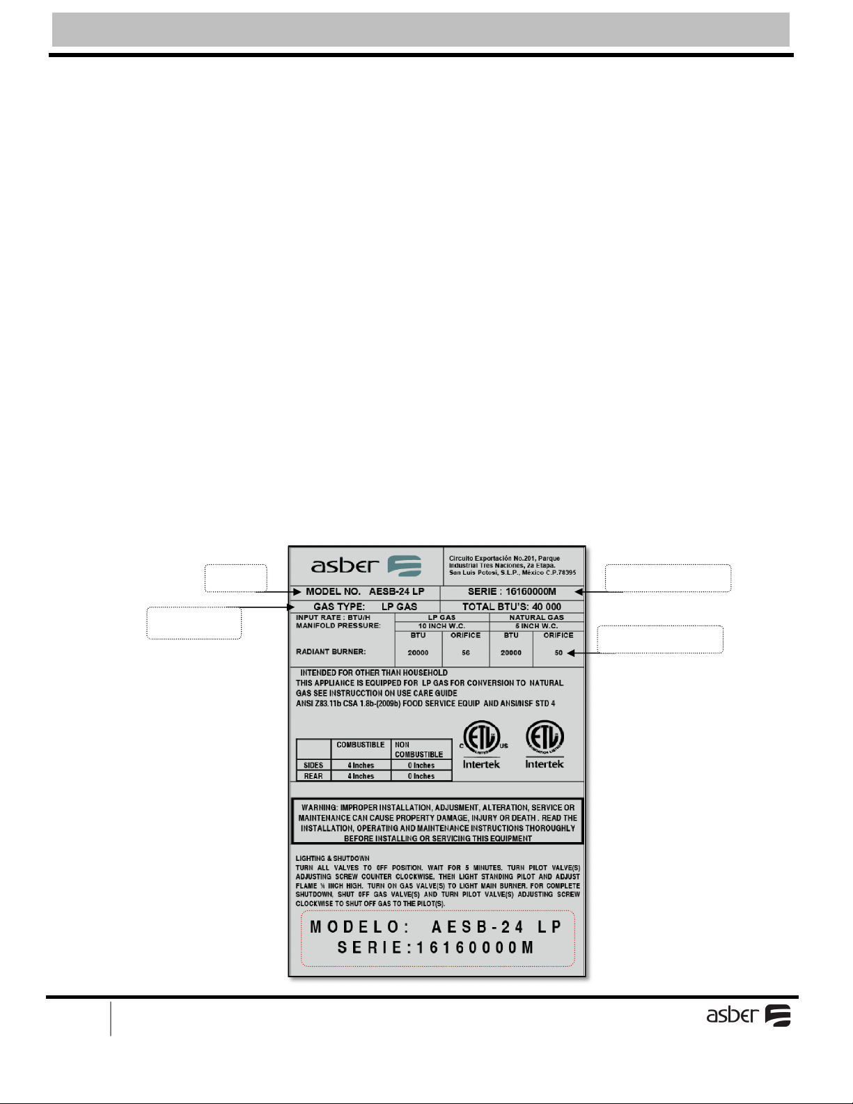
Model
Serial Number
Orifice
INSTALLATION
2.1 Transport, handling, unpacking, location.
2.2 Manufacturer’s identification label description.
2.3 Installation and assembly.
2.4 Gas Connections
2.1 Transport, handling, unpacking, location
Upon receiving your new ASBER Equipment, check the package and the machine for any damages that
may have occurred during transportation. Visually inspect the exterior of the package. If damaged, open
and inspect the contents with the carrier. Any damage should be noted and reported on the delivering
carrier’s receipt.
In the event that the exterior is not damaged, yet upon opening, there is concealed damage to the
equipment notify the carrier immediately. Notification should be made verbally as well as in written form.
Request an inspection by the shipping company of the damaged equipment. Retain all crating material
until inspection has been made. Finally, contact the dealer through which you purchased the unit.
2.2 Manufacturer’s identification label description
Information on this plate includes the model, serial number, BTU / hour input of the burners operating
gas pressure in inches WC, and whether the appliance is orifices for natural or propane gas.
When communicating with factory about a unit or requesting for special parts or information,
Rating plate data is essential for proper identification.
ASBER COOKING APPLIANCES MUST BE CONNECTED ONLY TO THE TYPE OF GAS
IDENTIFIED ON THE RATING PLATE
Gas Type
2asberprofessional.com
Page 5

asberprofessional.com
2.3 Installation and assembly
SHIPPING DAMAGE CLAIM PROCEDURE
The equipment is inspected and crated by skilled personnel before leaving our factory. The
transportation company assumes full responsibility for safe delivery upon acceptance of this equipment.
If shipment arrives damaged:
Visible loss or damage: Note on freight bill or express delivery and signed by person making
delivery.
File claim for damages immediately: Regardless of extent of damages.
Concealed loss or damage: If damage is noticed after unpacking, notify Transportation
Company immediately and file “Concealed Damage “claim with them. This should be done
within (15) days from date of delivery made to you. Retain container for inspection.
2.3.1 UNCRATING
Cut and remove the outer packaging. Cut the (4) clamps that hold the equipment to the skid lift the unit
off the skid.
2.3.2 INSTALLATION
WALL MOUNTING
3asberprofessional.com
Page 6

asberprofessional.com
1. - Place the support to the wall
2. - Put the equipment and use the screw to fasten the equipment to the support.
2.4 G
a
s
C
o
n
n
e
c
t
i
o
4asberprofessional.com
Page 7

asberprofessional.com
2.4 Gas Connections
The gas supply (service) line must be the same size or greater than the inlet line of the appliance.
ASBER appliances use a ¾” NPT inlet.
Pipe joint compound must be resistive to Natural or LP gas.
For equipment using propane gas do not install supply lines with a diameter less than ½ under any
circumstances.
All connections must be tested with a soapy water solution before lighting any pilots.
The appliance shall be connected to the fuel gas for which it was designed. No attempt shall be made to
convert the appliance from the gas specified on the rating plate for use with a different gas without
consulting the installation instructions, the serving gas supplier, or the appliance manufacturer for
complete instructions.
2.4.1 MANUAL SHUT OFF VALVE
This installer supplied valve must be in the gas service line ahead of the appliance regulator in
the gas stream and in a position accessible in the event of an emergency.
2.4.2 PRESSURE REGULATOR
Commercial cooking equipment must have a pressure regulator on the incoming service line for
safe and efficient operation; the gas pressure regulator supplied by ASBER must be installed at
the gas inlet of each piece of equipment.
The regulators supplied along with ASBER appliances, will have 3/4”inlet/outlet openings and
are adjusted at the factory for 5” WC (natural gas) or 10” WC (propane gas) depending on
customer’s ordering instructions.
Prior to connecting the regulator, check the incoming line pressure, as these regulators can only
withstand a maximum pressure of ½” PSI (14”WC). If the line pressure is beyond this limit, a
step down regulator will be required.
The arrow shown on the bottom of the regulator body shows the gas flow direction, it should
point downstream to the appliance. The BLUE air vent cap on the top is part of the regulator
and should not be removed.
Any adjustments to the regulator should be made by qualified service personnel only with the
proper equipment.
2.4.3 THIS APPLIANCE IS EQUIPPED FOR NATURAL GAS.
This appliance is equipped with orifices for operation with natural gas.For conversion to LP
(PROPANE) change the orifice selected in the table according burner type. Orifices necessary
for LP (PROPANE) conversion are provided on accessory box.Gas conversion must be
performed by qualified or authorized personnel
5asberprofessional.com
WARNING: To avoid the risk of serious personal injury or property damage, the range must be
converted correctly. Improper conversion or flame adjustment will produce carbon monoxide,
which is a poisonous gas.
Page 8

asberprofessional.com
A. Remove cap and snap out plastic plunger from bottom of cap.
To convert your range, follow the directions below
1. Check that the main gas supply has been shut off and the power supply cord is
disconnected.
2. Remove main top.
3. Convert pressure regulator. Your range is equipped with a convertible pressure regulator.
To convert, follow the illustrations below for the type of regulator on your range.
2.4.4 PRESSURE REGULATOR CONVERSION
B. Turn plunger over and snap back in original location.
Failure to install the pressure regulator will void the appliance warranty
2.5 Location
• Installation of the equipment should be performed by qualified, certified, and authorized personnel
who are familiar and experienced with local installation codes.
• Before Installation please read instructions completely and carefully.
• Do not remove permanently affixed labels, warnings or plates from the product.
• Please observe all local and national codes and ordinances
• Installation must conform with local codes, or in the absence of local codes, the National
Fuel Gas Code, ANSI Z223.1 (latest edition)
• The appliance must be isolated from gas supply piping system, by closing its individualmanual shut off
valve during any pressure testing of the gas supply piping system at test pressure equal to or less than
½ psi (3.45kpa)
6asberprofessional.com
Page 9

asberprofessional.com
MODEL
NON COMBUSTIBLE
COMBUSTIBLE
2.6 CLEARANCES
The appliance area must be kept free and clear of all combustibles
REAR SIDES REAR SIDES
SALAMANDRA 0Inches 0Inches 4Inches 4Inches
CHEESE MELTER 0Inches 0Inches 4Inches 4Inches
2.1 AIR SUPPLY & VENTILATION
The area in front of, around and above the appliance must be kept clear to avoid any obstruction of the
flow of combustion and ventilation air.
Adequate clearance must be maintained around the appliance for easy servicing. Provision should be
made for any commercial, heavy-duty cooking appliance exhaust combustion waste products to the
outside of the building. Usual practice is to place the appliance under an exhaust hood, which should be
constructed in accordance to the local codes. Strong exhaust fans in this hood or in the overall air
conditioning system can produce a slight vacuum in the room and / or cause air drafts, either of which
can interfere with the pilot or burner performance and could be difficult to diagnose. Air movement
should be checked during installation. Air openings or baffles may have to be provided in the room, if
pilot or burner outage problem persists.
7asberprofessional.com
Page 10

asberprofessional.com
WARINING
OPERATION
3.1 General information.
3.2Lighting Instructions.
3.3Daily Shut-Down.
3.1 General information.
Operation of this equipment must be performed by qualified or authorized personnel who have read and
are familiar with the functions of the equipment.
Hot oil and hot surfaces can cause severe burns. Use caution when operating the fryer.
Do not attempt to move the fryer filled whit hot oil or shortening.
Do not go near the area directly above the flue when fryer is operation.
Severe burns may be caused.
Drain hot oil in metal containers, do not use plastic buckets or glass containers.
3.2 LIGHTING INSTRUCTIONS
· Tum all valves or thermostats to the OFF position.
· Wait 5 minutes.
· Turn main gas supply ON and light pilot valves(s)
· Adjust pilot valve(s) screw counter clockwise more flame, screw clockwise less flame
· Adjust pilot flame ¼ inch high.
· Turn ON gas valve(s) to light main burner.
· For complete shutdown, shut OFF gas valve(s) and turn pilot valve(s) adjusting screw
clockwise to shut off gas to the pilot(s).
3.3 DAILY SHUT-DOWN
At the end of the day, turn the gas tap dial on the combination gas valve and the thermostat to OFF
position. Where applicable turn the power switch to OFF position. Filter the oil in all fryers.
MAINTENANCE
4.1 CLEANING
For continued performance efficiency and longevity of your Fryer it is essential to carry out a good
maintenance program.
8asberprofessional.com
Page 11

asberprofessional.com
4.1.1 DAILY
OPEN BURNERS / HOT PLATES
1. Remove all top grates.
2. Lift off the burners heads and venturies by raising the head slightly, sliding to the
rear andlifting upwards.
3. Wash off the above in hot soapy water.
4. Re-install parts in the reverse order.
GRIDDLES
1. Scrape with a nylon griddle scraper to remove the cooked spills.
When absolutely necessary use a fine grained stone to scrape.
2. Wipe away any griddle stone dust and food particles with burlap.
3. Wash with hot, soapy water, and then rinse with vinegar and water.
4. Rinse again with clear water.
5. Re-oil with shortening or liquid frying compound.
6. DO NOT FLOOD A HOT GRIDDLE WITH COLD WATER. This could cause
warping and griddle plate to crack.
BROILER
1. Remove large pieces of food residue and carefully scrape spillovers from the
drip tray below the cooking surface.
2. Wash all exterior and interior surfaces with hot soapy water solution. Do not use
any abrasives on any portion of the stainless or painted surfaces.
3. Cast iron grates should be scraped frequently with a wire brush and periodically
soaked in hot water solution to remove grease particles.
Never expose the grates to excessive heat for the purpose of burning excess
grease. Thispractice could shorten the useful life of the grates.
9asberprofessional.com
4.1.2 STAINLESS STEEL PARTS
Do not use steel wool, abrasive cloths, cleansers or powders to clean stainless steel surfaces.
All stainless steel parts should be wiped regularly with hot soapy water during the day and a
stainless steel liquid cleaner at the end of the day. To remove encrusted materials, soak in hot
water to loosen the material, and then use a wood or nylon scraper. NOT USE a metal knife,
spatula, or any other metal tool to scrape stainless steel. Scratches are almost impossible to
remove.
Page 12

asberprofessional.com
Pilot will not
a. No gas
a. Turn main gas valve “ON”
Pilot will not
a. Gas
tap dial not depressed
a. Depress and hold for at
Main burners
a. Pilot not lit
a. Light the pilot
Oil/shortening
a. Operating temperature too
a. Set at proper temperature.
Fryer shut
-
off,
a. Hi-limit cut off.
a. Note: cannot re
-
light the
TROUBLE SHOOTING
PROBLEM PROBABLE CAUSE REMEDY
light
stay lit
will not ignite
Fryer does not
heat up fast
b. Gas tap dial not set at “Pilot”
position and depressed.
and held long enough
b. Defective thermopile
c. Pilot flame not properly
adjusted
b. Thermopile not properly
installed in the pilot.
c. Gas tap dial not set at “ON”
position.
d. Thermostat not set at any
temperature.
e. Defective gas valve.
f. Defective hi-limit switch.
a. Insufficient gas.
b. Line clogged
c. Overloading the fryer.
b. Set gas tap dial on
combination gas valve to
“Pilot”. Depress and hold
while lighting.
least 30 sec.
b. Replace
c. Adjust pilot flame whit
pilot adjustment screw on
the combination valve.
b. Push in ad tightens. Pilot
flame should engulf the
thermopile.
c. Turn and set gas tap dial to
“ON” position.
d. Set thermostat to desired
temperature.
e. Replace
f. Replace.
a. Check gas pressure.
b. Remove and clean gas line
c. Cook smaller loads. Need
larger fryer!
scorches and
breaks down.
Temperature
cannot be
controlled
cannot re-light
pilot
10asberprofessional.com
high.
b. Thermostat out of calibration
c. Oil/shortening overused.
d. Oil/shortening not filtered
frequently.
a. Thermostat bulb out of proper
position.
b. Thermostat out of calibration.
c. Defective thermostat.
d. Defective gas valve.
b. Defective thermostat.
c. Thermostat out of calibration.
d. Hi-limit switch defective.
b. Re-calibrate
c. Replace
d. Replace
a. Relocate and secure at the
proper position.
b. Re-calibrate.
c. Replace.
d. Replace.
pilot until temperature of
oil drops to about 325°F.
call service, if uncertain.
b. Replace.
c. Re-calibrate
d. Replace.
Page 13

asberprofessional.com
ASBER
Circuito Exportación N° 201
Parque Industrial Tres Naciones
San Luís Potosí, S.L.P. México
13105 NW 47th Ave
Miami, Fl. 33054
www.asberprofessional.com
MULTI-SOLUTION MANUFACTURER OF FOODSERVICE EQUIPMENT
11asberprofessional.com
 Loading...