


AFMD-23
MERCHANDISER REFRIGERATORS AND FREEZERS
Manual for installation, use, and maintenance

Page2
ASBER – MERCHANDISER: Operations and Service Manual/Rev. JUN. 2015
Contents
1 RECEIVING AND INSPECTING THE EQUIPMENT .................................................................................... 3
2 SPECIFICATIONS .................................................................................................................................... 4
3 INSTALLATION ....................................................................................................................................... 6
3.1 UNCRATING ................................................................................................................................... 6
3.2 LOCATION ...................................................................................................................................... 6
3.3 DATA PLATE ................................................................................................................................... 7
3.4 LEVELING ....................................................................................................................................... 7
3.5 ELECTRICAL CONNECTIONS ........................................................................................................... 7
3.6 SHELVING INSTALLATION .............................................................................................................. 8
4 OPERATION ........................................................................................................................................... 9
4.1 ANALOG THERMOSTAT ................................................................................................................. 9
4.2 ELECTRONIC CONTROLLER .......................................................................................................... 10
5 MAINTENANCE .................................................................................................................................... 11
5.1 GASKET ........................................................................................................................................ 12
5.2 DOORS/HINGES ........................................................................................................................... 13
5.3 DRAIN .......................................................................................................................................... 13
6 WIRING DIAGRAMS ............................................................................................................................. 14
7 TROUBLE SHOOTING ........................................................................................................................... 23
Limited Warranty ...................................................................................................................................... 24

Page3
ASBER – MERCHANDISER: Operations and Service Manual/Rev. JUN. 2015
1 RECEIVING AND INSPECTING THE EQUIPMENT
Up on receiving your new Asber Refrigerator, check the package and the machine for any
damages that may have occurred during transportation. Visually inspect the exterior of the
package. I f damaged, open and inspect the contents with the carrier. Any damage should be
noted and reported on the delivering carrier’s receipt.
In the event that the exterior is not damaged, yet up on opening, there is concealed damage to
the equipment notify, the carrier immediately. Notification should be made verbally as well as
in written form. Request an inspection by the shipping company of the damaged equipment.
Retain all crating material until inspection has been made. Contact the dealer through which
you purchased the unit.
Check the compressor compartment housing and visually inspect the refrigeration package. Be
sure lines are secure and base is still intact.
A NOTE FROM OUR QUALITY CONTROL MANAGER
CONGRATULATIONS ON YOUR NEW PURCHASE. WE WOULD LIKE TO WELCOME
YOU TO THE ASBER TEAM. THE UNIT IN FRONT OF YOU IS A GREAT PIECE OF
EQUIPMENT THAT WILL BECOME ONE OF YOUR MOST RELAIBLE TOOLS IN YOUR
DAILY OPERATIONS FOR YEARS TO COME!
PRIOR TO SHIPPING YOUR UNIT, OUR TRAINED SERVICE TECHNICIANS TESTED
YOUR UNIT FOR A PERIOD OF 12 HOURS. THIS PERFORMANCE TEST WAS
RECORDED AND A COPY OF THE RESULTS IS INCLUDED WITH THIS SERVICE
MANUAL. DURING THIS TEST, OUR HIGHLY QUALIFIED PERSONNEL INSPECTED
YOUR MACHINE FOR LEAKS, LOSE COMPONENTS, AND IMPROPER NOISE
LEVELS. WE ALSO TESTED THE COOLING PERFORMANCE IN AN EFFORT TO GIVE
YOU THE BEST AND MOST RELAIBLE UNIT POSSIBLE.
Page4
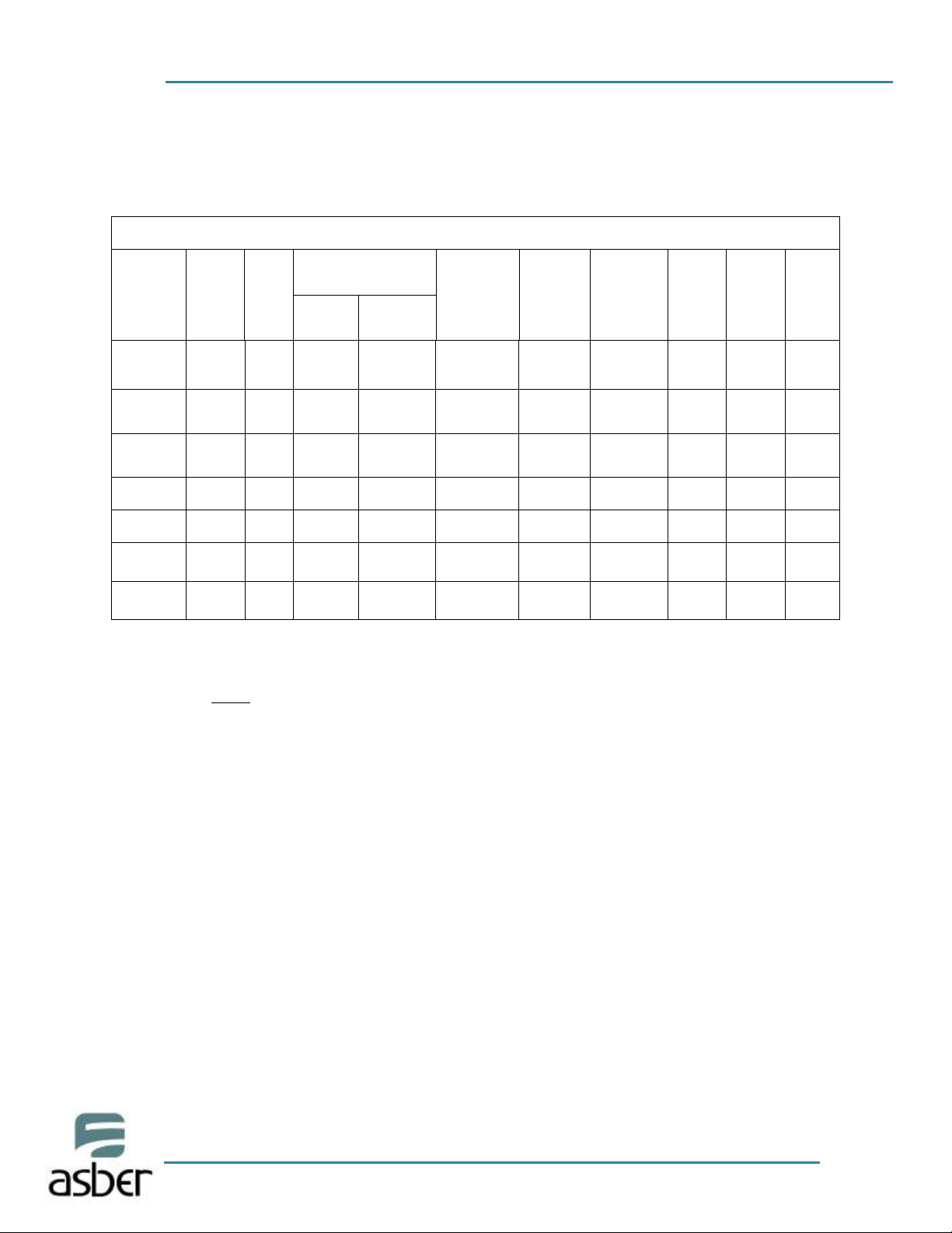
REACH IN MERCHANDISERS AND FREEZERS, GENERAL SPECS
Model
Capac.
(Cu.Ft.)
#of
Shvls
Temperature
Operation
Pressure
in
Suction Line*
Super-
Heat**
BTU
Ref.
Amount
Ref.
Type
Ship
Weight
Set
Point
Cut in
ARM-10
9.8
4
5°C/41°F
-3°C A 0°C
(27°F y 32°F)
10-16PSIG
7°C/13°F
1400
9.8 oz
R-134a
203
ARM-17
16
4
5°C/41°F
-3°C A 0°C
(27°F y 32°F)
10-16PSIG
7°C/13°F
1800
9.8 oz
R-134a
216
ARMD-23
23
4
5°C/41°F
-3°C A 0°C
(27°F y 32°F)
10-16PSIG
7°C/13°F
1800
9.8 oz
R-134a
262
ARMD-37
37
8
0°C/32°F
5°C/41°F
10-16PSIG
7°C/13°F
2400
17.28oz
R-134a
373
ARMD-49
49
8
0°C/32°F
5°C/41°F
10-16PSIG
7°C/13°F
2400
17.28oz
R-134a
424
AFM-17
16
4
-22°C/-8F
-18°C/0°F
12-16PSIG
4°C/7°F
1900
16.6oz
R-404A
216
AFMD-23
23
4
-22°C/-8F
-18°C/0°F
12-16PSIG
4°C/7°F
1900
16.6 oz
R-404A
262
2 SPECIFICATIONS
ASBER – MERCHANDISER: Operations and Service Manual/Rev. JUN. 2015
Note:
* The pressure in the suction line is recommended at 32°C / 90°F maximum of ambient
temperature.
**Superheat measured in the outlet of the evaporator at 32°C / 90°F
Page5
ASBER – MERCHANDISER: Operations and Service Manual/Rev. JUN. 2015
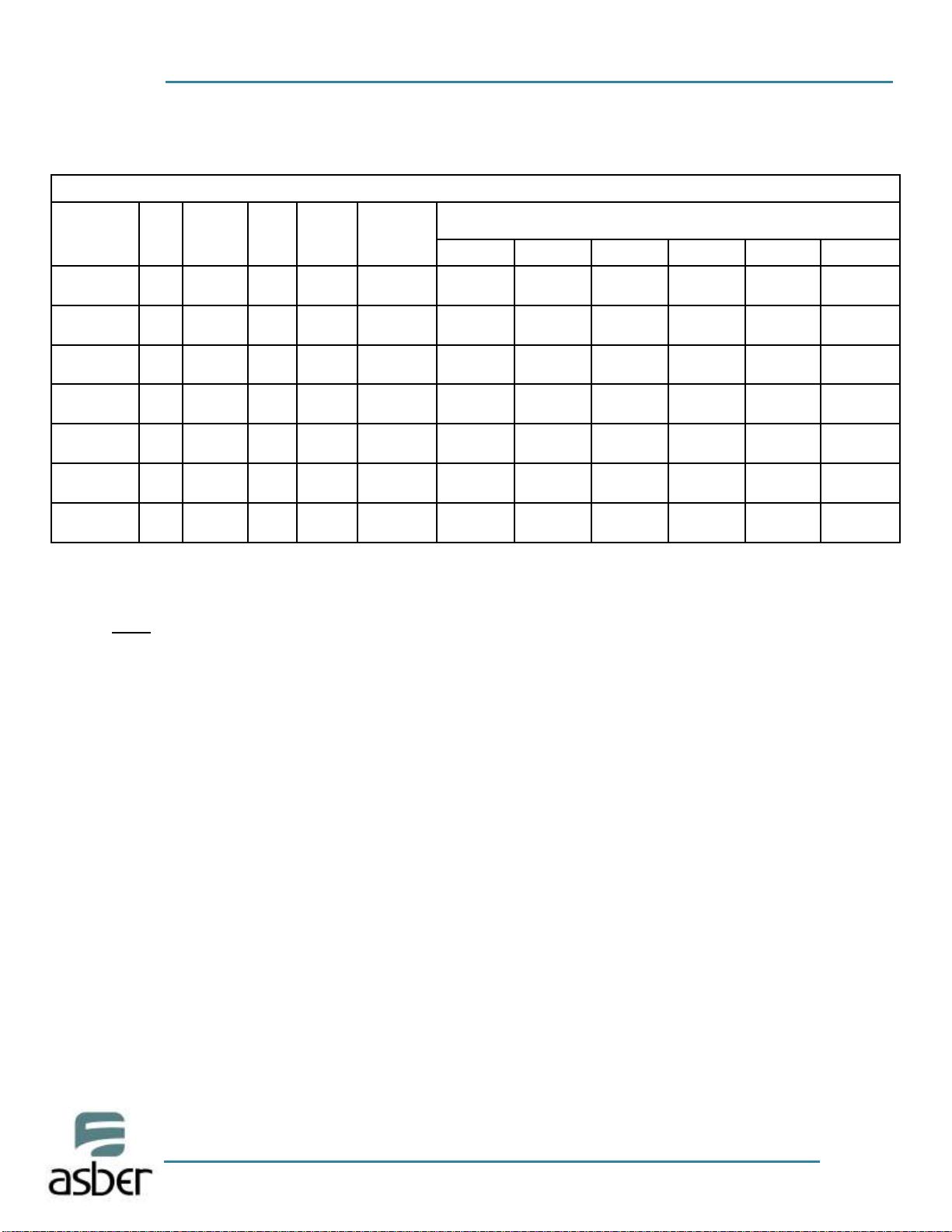
REACH IN MERCHANDISERS AND FREEZERS, ELECTRICAL SPECS
Models
HP Voltage
Amp.
Max.
NEMA
Plug
Breaker
Size*
Wire gauge recommended for 2% voltage drop in supply
circuits **
40 ft ***
60 ft
80 ft
100 ft
120 ft
140 ft
ARM-10
1/4
115
220
5.8
3.2
5-15P
2P+TT
15 amp
10 amp
14 AWG
14 AWG
14 AWG
14 AWG
12 AWG
14 AWG
12 AWG
14 AWG
12 AWG
14 AWG
10 AWG
12 AWG
ARM-17
3/4
115
220
5.8
3.2
5-15P
2P+TT
15 amp
10 amp
14 AWG
14 AWG
14 AWG
14 AWG
12 AWG
14 AWG
12 AWG
14 AWG
10 AWG
14 AWG
10 AWG
12 AWG
ARMD-23
1/4
115
5.8
3.2
5-15P
2P+TT
15 amp
10 amp
14 AWG
14 AWG
12 AWG
14 AWG
12 AWG
14 AWG
10AWG
14 AWG
10 AWG
14 AWG
10 AWG
12 AWG
ARMD-37
1/3
3/8
115
220
6.9
3.5
5-15P
2P+TT
15 amp
10 amp
14 AWG
14 AWG
12 AWG
14 AWG
12 AWG
14 AWG
10 AWG
14 AWG
10 AWG
12 AWG
8 AWG
12 AWG
ARMD-49
1/3
3/8
115
220
6.9
3.5
5-15P
2P+TT
15 amp
10 amp
14 AWG
14 AWG
12 AWG
14 AWG
10 AWG
14 AWG
10 AWG
12 AWG
8 AWG
12 AWG
8 AWG
12 AWG
AFM-17
3/4
115
220
8.8
4.5
5-15P
2P+TT
15 amp
10 amp
14 AWG
14 AWG
12 AWG
14 AWG
10 AWG
14 AWG
10 AWG
12 AWG
8 AWG
12 AWG
8 AWG
12 AWG
AFMD-23
3/4
115
220
8.8
4.5
5-15P
2P+TT
20 amp
10 amp
12 AWG
14 AWG
10 AWG
12 AWG
8 AWG
12 AWG
8 AWG
12 AWG
8 AWG
12 AWG
6 AWG
12 AWG
Note:
*Breaker sizes are recommended by the manufacturer to protect the equipment by
overload; this breaker only must be dedicated for the equipment.
** If the equipment is installed faraway of the circuit breaker, these are the wire gauge
recommend to connect the appliance; if the distance is higher that the chart values, please
contact an electrician.
***Distance in feet from the breaker or the power supply to the appliance.
Page6
ASBER – MERCHANDISER: Operations and Service Manual/Rev. JUN. 2015
3 INSTALLATION
3.1 UNCRATING
Remove the outer packaging. Cut the 4 clamps that hold the refrigerator to the skid. Lift the
unit off the skid.
If machine was laid down during this operation, remember to leave the cabinet
up right for 24 hours before connecting to power source.
3.2 LOCATION
Units represented in this manual are intended for indoor use only. Be sure the location chosen
has a floor strong enough to support the total weigh to the unit and its contents. For the most
efficient operation, be sure to provide at least three (3) inches between sides, back and top of
the unit.
THE MACHINES NEEDS TO BE INSTALLED 2 FEET AWAY FROM ANY HEAT SOURCES.
The unit should not be installed under ambient temperatures higher than 100 °F.
If the relative humidity is higher than 60 %, the door frames may sweat water. This is not a
malfunctioning of the unit.
WARNING
The following actions will void your warranty:
Modification of power cord.
Connecting the unit to any extension cord.
Neglecting to install the castors or optional legs.
Inside cabinet:
The first cleaning must happen when you unpack the unit and before it is turned ON. For
this, you have to clean the unit with warm water and mild detergent. When it is cleaned and
dry, proceed to install accessories and plug your unit in to a dedicated outlet. WAIT 24 HOURS
BEFORE PLACING PRODUCT IN THE UNIT. This will guarantee that it is working properly.
Consequential damages are not covered under warranty.
Outside cabinet:
Be sure that the unit has access to ample air to breathe. Avoid hot corners and locations near
stoves and ovens. It is recommended the unit be installed no closer than 3” from any wall. The
place where the refrigerator is placed must be open and clean. This will reduce the amount of
debris and dirt on the condenser fan and coil.
Page7
ASBER – MERCHANDISER: Operations and Service Manual/Rev. JUN. 2015
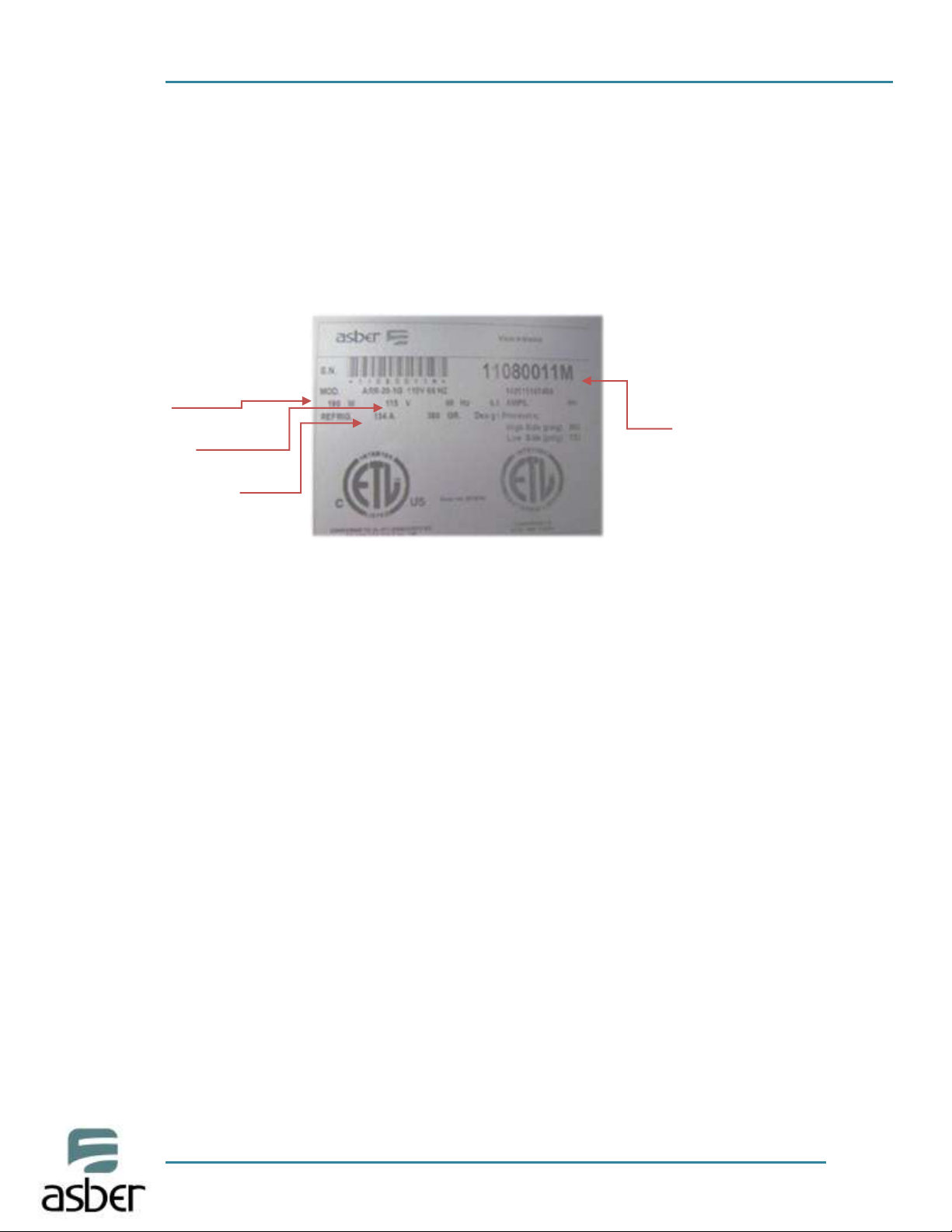
Model
Electrical
Refrigerant Type
SERIAL NUMBER FOR
THE EQUIPMENT
(8 digits and ends in
“M”)
3.3 DATA PLATE
The data plate is located inside the cabinet, near the top front, left corner. Under any
circumstances should the data plate be removed from the unit. The data plate is essential to
identify the particular features of your machine and i t is of great benefit to installers,
operators, and maintenance personnel. It is recommended that, in the event the data plate is
removed, you copy down the essential information in this manual for reference before
installation. Removal of data plate will void the warranty.
3.4 LEVELING
Set unit in its final location. A level cabinet looks better and will perform better. Effective
condensate removal and door operation will be effected by leveling. Machine must be leveled
front to back and side to side with a level tool. Castors ki t wi ll include shims for leveling.
Insert the shim between the castor and the frame rail. (See installation of castors). Lock front
castors so cabinet does not move. Ensure drain hose is inside drain pan.
3.5 ELECTRICAL CONNECTIONS
Refer to the amperage data in this manual, or on data plate, and your local code or the
National Electrical Code to be sure unit is connected to the proper power source. Verify
correct incoming voltage according to the Data Plate information.
Do not, under any circumstances, cut or remove the ground prong from the power cord.
Asber units must be properly grounded.
NEVER USE AN EXTENSION CORD! Asber will not warranty any unit that has been
connected to an extension cord.
Asber equipment must be grounded and connected in accordance with NEC Article 422
Appliances.
Page8
ASBER – MERCHANDISER: Operations and Service Manual/Rev. JUN. 2015
DANGER:
Power must be turned off and disconnected from the power source whenever
performing maintenance, repair or cleaning the condensing unit.
If machine is still running when power is off, disconnect power at the circuit breaker
before unplugging the machine.
WARNING:
Machine and compressor warranties are void if failure is due to improper electrical
installation.
3.6 SHELVING INSTALLATION
Hook shelf rails onto shelf pilasters
Position all shelf rails equal in distance from the floor for level shelves
Wire shelves are oriented so that cross support bars are facing down
Note: Single door Reach-include an air flow guard on the rear of the shelves as well as a lip to
maintain an air space at the rear of the cabinet
Place shelves on shelf clips, making sure all corners are seated properly.
 Loading...