

Page 1
Aruba Instant On AP22 Access Point
System
Radio
Installation Guide
The Aruba Instant On AP22 access point delivers high performance concurrent 2.4 GHz and 5 GHz Wi-Fi 6
(802.11ax) functionality with MIMO radios (2x2 in 2.4 GHz, 2x2 in 5 GHz), while also supporting legacy 802.11a/b/
g/n/ac wireless services.
Package Contents
1 x AP22 access point
1 x Mount bracket
1 x Ethernet cable
If you have ordered AP22 bundle, the package would also include a power supply unit to power the AP through
an electrical power outlet.
Inform your supplier if there are any incorrect, missing, or damaged parts. If possible, retain the carton,
including the original packing materials. Use these materials to repack and return the unit to the supplier if
needed.
Hardware Overview
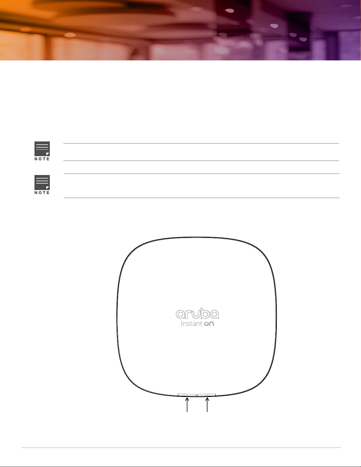
Figure 1 AP22 Front View
Rev01 | April 2020 1
Page 2
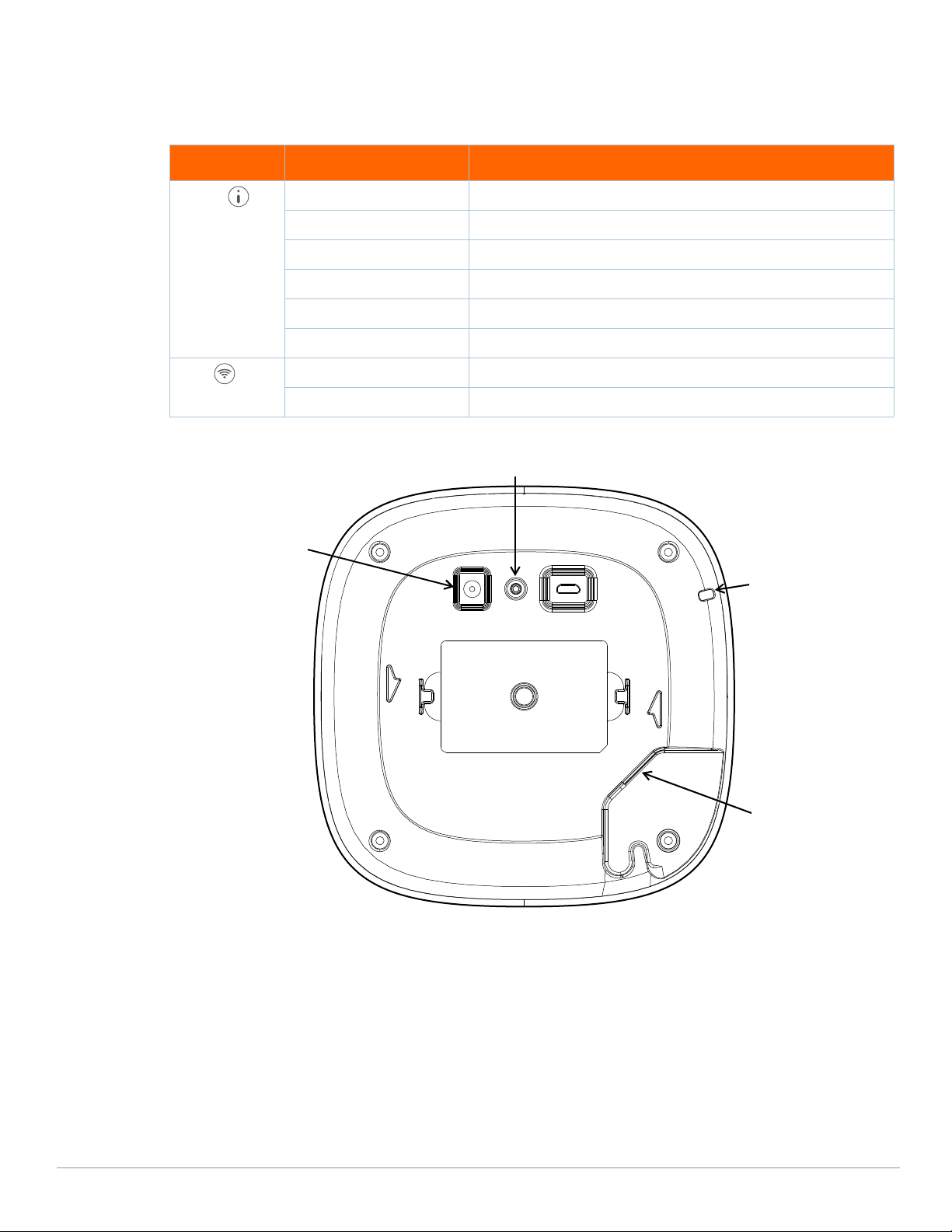
LEDs
E0
Reset Button
DC Power Socket
Kensington Lock Slot
The AP22 access point has two LEDs that indicate the system and radio status of the device.
Table 1 AP22 Access Point LEDs Status
LED Color/State Meaning
System No Lights Device has no power
Blinking Green Device is starting
Alternating Green/Amber Device is ready for setup
Solid Green Device is ready
Solid Amber Device has detected a problem
Solid Red Device has an issue- immediate action required
Radio No Lights Wi-Fi is not ready, wireless clients cannot connect
Solid Green Wi-Fi is ready, wireless clients can connect
Figure 2 AP22 Rear View
Ethernet Port
The AP22 is equipped with a 10/100/1000Base-T auto-sensing MDI/MDX Ethernet port (E0). This E0 port supports
wired-network connectivity, and Power over Ethernet (PoE) from IEEE 802.3af and 802.3at compliant PoE power
sources, such as a PoE midspan injector or a network switch.
Kensington Lock Slot
The AP22 access point is equipped with a Kensington lock slot for additional security.
2 Aruba Instant On AP22 Access Point | Installation Guide
Page 3
Reset Button
The reset button located on the bottom of the device can be used to reset the access point to factory default
settings.
There are two ways to reset the access point to factory default settings:
Reset the AP during normal operation
Press and hold down the reset button using a small, narrow object such as a paper clip for more than 10
seconds during normal operation.
Reset the AP while powering up
1. Press and hold down the reset button using a small, narrow object such as a paper clip while the access point
is not powered on (either via DC power or PoE).
2. Connect the power supply (DC or PoE) to the access point while the reset button is being held down.
3. Release the reset button on the access point after 15 seconds.
Power
If PoE is not available, a proprietary Aruba power adapter can be used to power the AP22 access point. This
power adapter is available in the box if you buy the AP22 and power adapter bundle. For details, refer to the
ordering information in the AP22 data sheet at https://www.ArubaInstantOn.com/resources.
When both PoE and DC power sources are available, the DC power source takes precedence. The access point
simultaneously draws a minimal current from the PoE source. In the event that the DC source fails, the access
point switches to the PoE source.
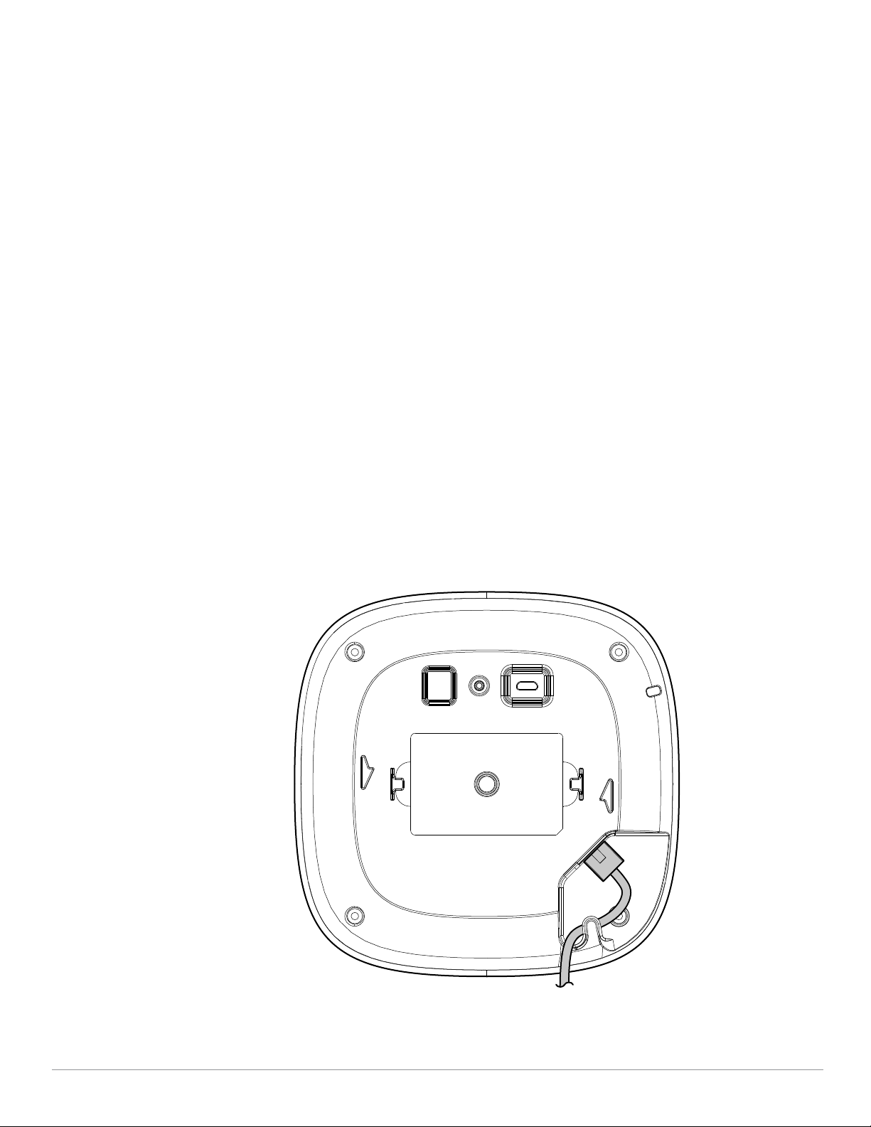
Cable Clip
The cable clip on the rear of the access point is used to organize Ethernet cable, as shown in Figure 3. The use of
the cable clip is optional and does not support all types of cables and plugs.
Figure 3 Cable Clip
Aruba Instant On AP22 Access Point | Installation Guide 3
Page 4
Before You Begin
!
!
!
!
Refer to the sections below before beginning the installation process.
The AP22 access point is designed in compliance with governmental requirements so that only authorized
network administrators can change the settings.
Identifying Specific Installation Locations
Each location should be as close as possible to the center of the intended coverage area and should be free from
obstructions or obvious sources of interference. These RF absorbers/reflectors/interference sources will impact
RF propagation and should have been accounted for during the planning phase and adjusted.
Use of this equipment adjacent to or stacked with other equipment should be avoided because it could result in
improper operation. If such use is necessary, this equipment and the other equipment should be observed to
verify that they are operating normally.
Identifying Known RF Absorbers/Reflectors/Interference Sources
Identifying known RF absorbers, reflectors, and interference sources while in the field during the installation
phase is critical. Make sure that these sources are taken into consideration when you attach an access point to its
fixed location.
RF absorbers include:
Cement/concrete—Old concrete has high levels of water dissipation, which dries out the concrete, allowing
for potential RF propagation. New concrete has high levels of water concentration in the concrete, blocking
RF signals.
Natural Items—Fish tanks, water fountains, ponds, and trees
Brick
RF reflectors include:
Metal Objects—Metal pans between floors, rebar, fire doors, air conditioning/heating ducts, mesh windows,
blinds, chain link fences (depending on aperture size), refrigerators, racks, shelves, and filing cabinets.
Do not place an access point between two air conditioning/heating ducts. Make sure that access points are
placed below ducts to avoid RF disturbances.
RF interference sources include:
Microwave ovens and other 2.4 or 5 GHz objects (such as cordless phones)
Cordless headset such as those used in call centers or lunch rooms
Portable RF communications equipment (including peripherals such as antenna cables and external antennas)
should be used no closer than 7.87 inches (20 cm) to any part of the access point. Otherwise, degradation of the
performance of this equipment could result.
Access Point Installation
The installer is responsible for securing the access point onto the ceiling tile rail in accordance with the steps
below. Failure to properly install this product may result in physical injury and/or damage to property.
Use of accessories, transducers and cables other than those specified or provided by the manufacturer of this
equipment could result in increased electromagnetic emissions or decreased electromagnetic immunity of this
equipment and result in improper operation.
The AP22 access point ships with a mount bracket to install the access point to a 9/16” or 15/16” ceiling tile rail,
or on a solid surface, such as a wall or a hard ceiling.
4 Aruba Instant On AP22 Access Point | Installation Guide
Page 5
The following sections provide instructions on how to use this mount bracket.
Installing the Access Point to a Ceiling Tile Rail
1. Pull the necessary cables through a prepared hole in the ceiling tile near where the access point will be
placed.
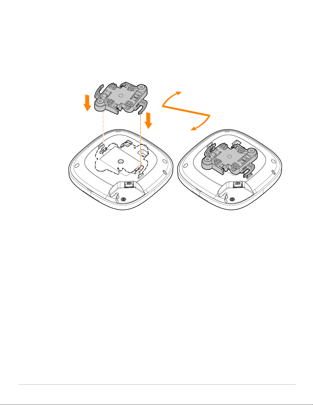
2. Place the mount bracket against the back of the access point with the mount bracket at an angle of
approximately 30 degrees to the tabs (see Figure 4).
3. Twist the mount bracket clockwise until it snaps into place in the tabs (see Figure 4).
Figure 4 Attaching the Mount Bracket to the AP
4. Hold the access point next to the ceiling tile rail with the mounting slots at approximately a 30-degree angle
to the ceiling tile rail (see Figure 5 and Figure 6). Make sure that any cable slack is above the ceiling tile.
5. Pushing toward the ceiling tile, rotate the access point clockwise until the device clicks into place on the
ceiling tile rail.
Aruba Instant On AP22 Access Point | Installation Guide 5
Page 6
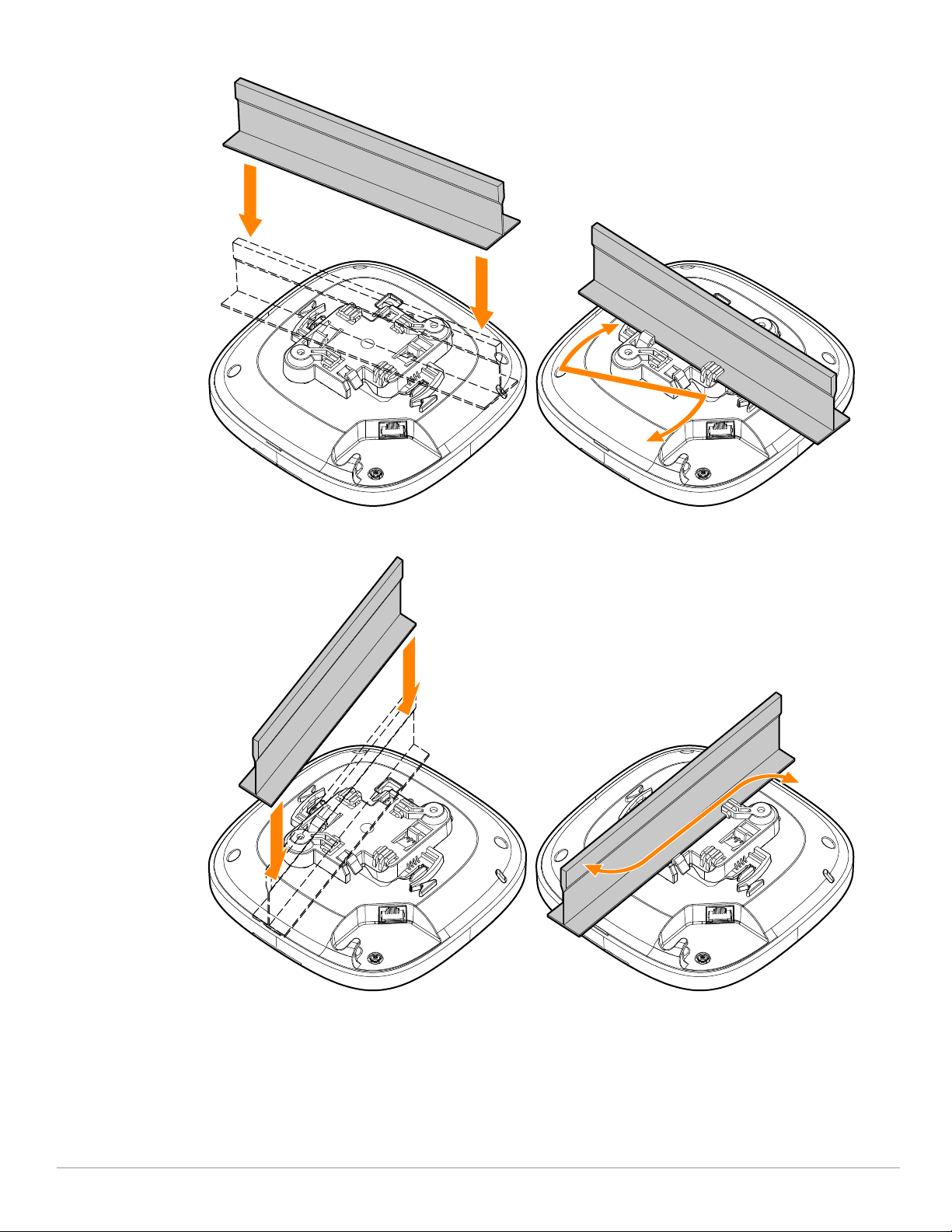
Figure 5 Mounting the AP to a 15/16” Ceiling Rail
Figure 6 Mounting the AP to a 9/16” Ceiling Rail
Installing the Access Point to a Solid Surface
1. Attach the mount bracket to any solid surface, such as a wall or hard ceiling, as shown in
a. Install any necessary wall anchors. Wall anchors are not included in the package.
b. Align the screw holes in the mount bracket with the previously installed anchors or demarcated screw
points.
6 Aruba Instant On AP22 Access Point | Installation Guide
Figure 7.
Page 7
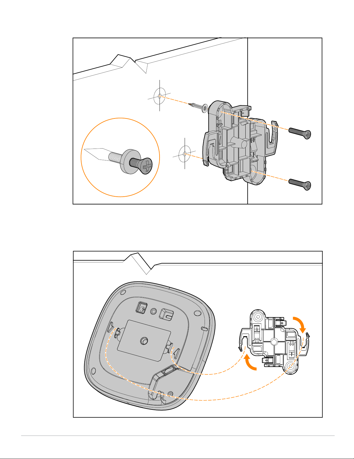
c. Insert two screws to secure the mount bracket. Screws are not included in the package.
Figure 7 Attaching the Mount Bracket to a Solid Surface
2. Attach the access point to the secured mount bracket as shown in Figure 8.
a. Align the access point with the mount bracket, placing the access point so that it’s mounting tabs are at an
angle of approximately 30 degrees to the mount bracket.
3. Pushing towards the solid surface, rotate the access point clockwise until it clicks into place (see Figure 8).
Figure 8 Attaching the Access Point to the Mount Bracket
Aruba Instant On AP22 Access Point | Installation Guide 7
Page 8
Verifying Post-Installation Connectivity
!
!
The integrated LEDs on the access point can be used to verify that the access point is receiving power and
initializing successfully (see
Table 1).
Mobile Application Installation
Click the Apple App Store or Google Play badge below to download and install the Aruba Instant On mobile app
to your phone. Launch the app and follow the instructions to complete the setup. Alternately, simply search for
“Aruba Instant On” app within Apple App Store or Google Play.
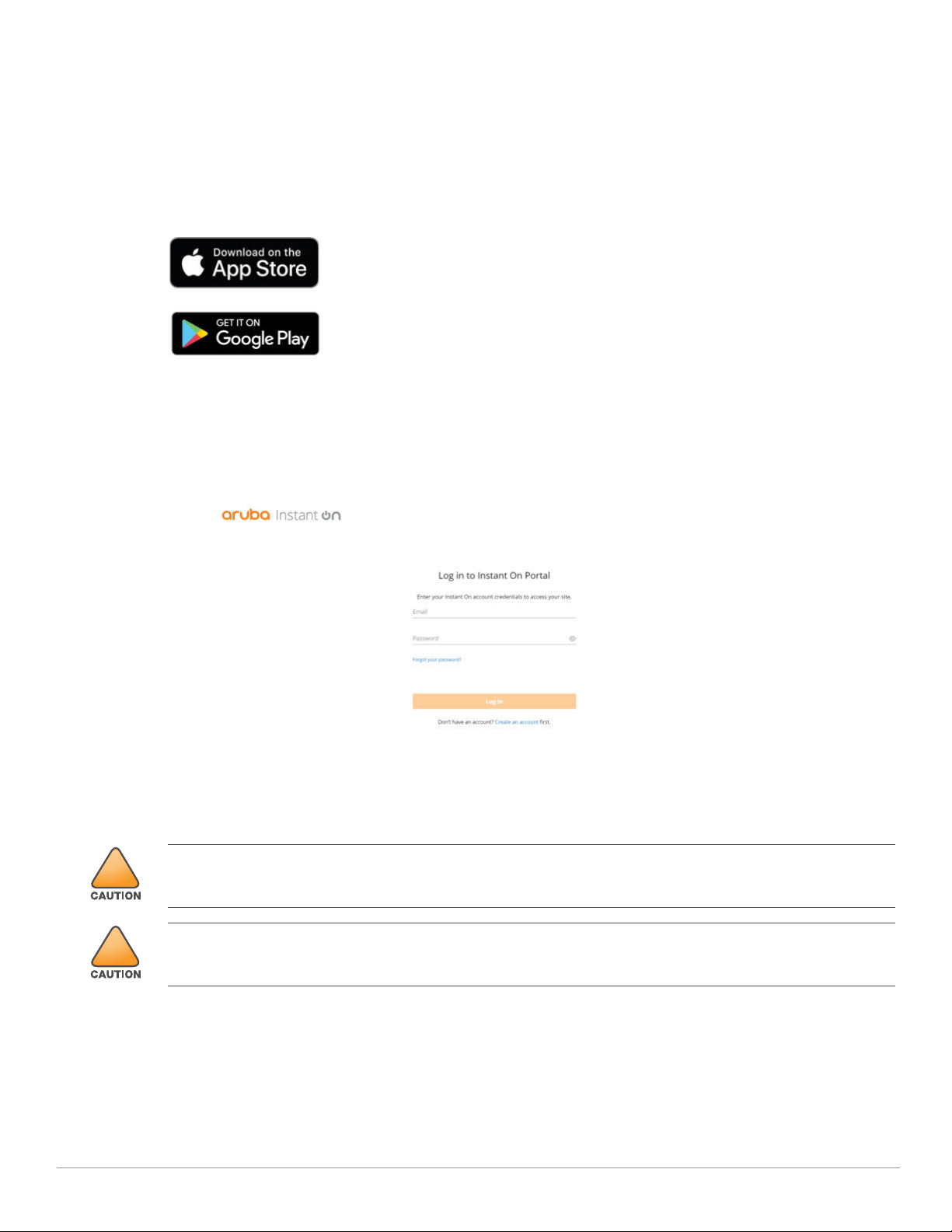
Log in to Instant On Portal
Alternately, you can set up the Aruba Instant On access point from a web browser. Open a web browser and
https://portal.ArubaInstantOn.com in the address bar to access the Aruba Instant On portal login screen.
enter
In the login screen, enter your Instant On account credentials to access your site.
Figure 9 Instant On Portal Login Screen
Electrical and Environmental Specifications
All Aruba access points should be professionally installed by an Aruba Certified Mobility Professional (ACMP).
The installer is responsible for ensuring that grounding is available and meets applicable national and electrical
codes.
Tous les points d'accès Aruba doivent impérativement être installés par un professionnel agréé. Ce dernier doit
s'assurer que l'appareil est mis à la terre et que le circuit de mise à la terre est conforme aux codes électriques
nationaux en vigueur.
Electrical
Ethernet:
E0 port: 10/100/1000BaseT auto-sensing MDI/MDX wired RJ45 network connectivity port
Power:
12V DC power interface, support powering through AC-to-DC power adapter
8 Aruba Instant On AP22 Access Point | Installation Guide
Page 9
Power over Ethernet (PoE): 802.3af or 802.3at compliant source
!
!
!
!
If a power adapter other than the Aruba-approved adapter is used in the US or Canada, it should be NRTL listed,
with an output rated 12Vdc, minimum 2A, marked “LPS” and “Class 2”, and suitable for plugging into a standard
power receptacle in the US and Canada.
Environmental
Operating temperature: 0°C to +40°C (+32°F to +104°F)
Operating humidity: 5% to 93% non-condensing
Regulatory Model Number
AP22 RMN: APIN0505
Safety and Regulatory Compliance
RF Radiation Exposure Statement: This equipment complies with FCC RF radiation exposure limits. This
equipment should be installed and operated with a minimum distance of 7.87 inches (20cm) between the
radiator and your body for 2.4 GHz and 5 GHz operations. This transmitter must not be co-located or operating
in conjunction with any other antenna or transmitter.
Déclaration de la concernant l’exposition aux rayonnements à fréquence radioélectrique (FR): Cet
appareil est conforme aux limites d’exposition aux rayonnements FR établies. Il doit être installé et utilisé à une
distance minimale de 20 cm (7.87 pouces) entre le radiateur et votre corps, qu’il opère sur la bande 2,4 GHz ou 5
GHz. Cet émetteur ne doit pas être installé ou utilisé à proximité immédiate d’une autre antenne ni d’un autre
transmetteur.
Changes or modifications to this unit not expressly approved by the party responsible for compliance could void
the user’s authority to operate this equipment.
Toute modification effectuée sur cet équipement sans l'autorisation expresse de la partie responsable de la
conformité est susceptible d'annuler son droit d'utilisation.
Federal Communication Commission
This device complies with Part 15 of the FCC Rules. Operation is subject to the following two conditions: (1)this
device may not cause harmful interference, and (2) this device must accept any interference received, including
interference that may cause undesired operation.
This equipment has been tested and found to comply with the limits for a Class B digital device, pursuant to Part
15 of the FCC Rules. These limits are designed to provide reasonable protection against harmful interference in a
residential installation. This equipment generates, uses and can radiate radio frequency energy and, if not
installed and used in accordance with the manufacturer’s instructions, may cause harmful interference to radio
communications. However, there is no guarantee that interference will not occur in a particular installation. If
this equipment does cause harmful interference to radio or television reception, which can be determined by
turning the equipment off and on, the user is encouraged to try to correct the interference by one or more of the
following measures:
Reorient or relocate the receiving antenna.
Increase the separation between the equipment and receiver.
Connect the equipment to an outlet on a circuit different from that to which the receiver is connected.
Consult the dealer or an experienced radio or TV technician for help.
Industry Canada
This Class B digital apparatus meets all of the requirements of the Canadian Interference-Causing Equipment
Regulations.
Aruba Instant On AP22 Access Point | Installation Guide 9
Page 10

In accordance with Industry Canada regulations, this radio transmitter and receiver may only be used with an
antenna, the maximum type and gain of which must be approved by Industry Canada. To reduce potential radio
interference, the type of antenna and its gain shall be chosen so that the equivalent isotropic radiated power
(EIRP) does not exceed the values necessary for effective communication.
This device complies with Industry Canada's license-exempt RSS regulations. Operation of this device is subject
to the following two conditions: (1) this device may not cause interference, and (2) this device must accept any
interference, including interference that may cause undesired operation.
When operated in the 5.15 to 5.25 GHz frequency range, this device is restricted to indoor use to reduce the
potential for harmful interference with co-channel Mobile Satellite Systems.
Déclaration d’Industrie Canada
Conformément aux réglementations d’Industrie Canada, cet émetteur-récepteur radio doit être utilisé
uniquement avec une antenne dont le type et le gain maximal doivent être approuvés par Industrie Canada.
Pour réduire les interférences radio potentielles, le type d’antenne et son gain doivent être choisis de façon à ce
que la puissance isotrope rayonnée équivalente (PIRE) ne dépasse pas les valeurs nécessaires à une
communication efficace.
Ce périphérique est conforme aux règlements RSS exempts de licence d’Industrie Canada. L’utilisation de ce
périphérique est soumise aux deux conditions suivantes : (1) ce périphérique ne doit pas provoquer
d’interférences, et (2) ce périphérique doit accepter toute interférence, y compris les interférences susceptibles
de provoquer un dysfonctionnement.
En cas d'utilisation dans la plage de fréquences de 5,15 à 5,25 GHz, cet appareil doit uniquement être utilisé en
intérieur afin de réduire les risques d'interférence avec les systèmes satellites mobiles partageant le même
canal.
European Union Regulatory Conformance
The Declaration of Conformity made under Radio Equipment Directive 2014/53/EU is available for viewing at:
www.hpe.com/eu/certificates. Select the document that corresponds to your device’s model number as it is
indicated on the product label.
Wireless Channel Restrictions
5150-5350MHz band is limited to indoor only in the following countries; Austria (AT), Belgium (BE), Bulgaria (BG),
Croatia (HR), Cyprus (CY), Czech Republic (CZ), Denmark (DK), Estonia (EE), Finland (FI), France (FR), Germany (DE),
Greece (GR), Hungary (HU), Iceland (IS), Ireland (IE), Italy (IT), Latvia (LV), Liechtenstein (LI), Lithuania (LT),
Luxembourg (LU), Malta (MT), Netherlands (NL), Norway (NO), Poland (PL), Portugal (PT), Romania (RO), Slovakia
(SK), Slovenia (SL), Spain (ES), Sweden (SE), Switzerland (CH), Turkey (TR), United Kingdom (UK).
Radio Frequency Range MHz Max EIRP
BLE/Zigbee 2402-2480 9 dBm
2412-2472 20 dBm
5150-5250 23 dBm
Wi-Fi
5250-5350 23 dBm
5470-5725 30 dBm
5725-5850 14 dBm
Medical
1. Equipment not suitable for use in the presence of flammable mixtures.
2. Connect to only IEC 60950-1 or IEC 60601-1 certified products and power sources. The end user is
responsible for the resulting medical system complies with the requirements of IEC 60601-1.
3. Wipe with a dry cloth, no additional maintenance required.
4. No serviceable parts, the unit must be sent back to the manufacturer for repair.
10 Aruba Instant On AP22 Access Point | Installation Guide
Page 11
5. No modifications are allowed without Aruba approval.
!
!
This device is intended for indoor use in professional healthcare facilities.
This device has no IEC/EN60601-1-2 essential performance.
Use of this equipment adjacent to or stacked with other equipment should be avoided because it could result in
improper operation. If such use is necessary, this equipment and the other equipment should be observed to
verify that they are operating normally.
Compliance is based on the use of Aruba approved accessories.
Use of accessories, transducers and cables other than those specified or provided by the manufacturer of this
equipment could result in increased electromagnetic emissions or decreased electromagnetic immunity of this
equipment and result in improper operation.
Brazil
Este equipamento não tem direito à proteção contra interferência prejudicial e não pode causar interferência
em sistemas devidamente autorizados.
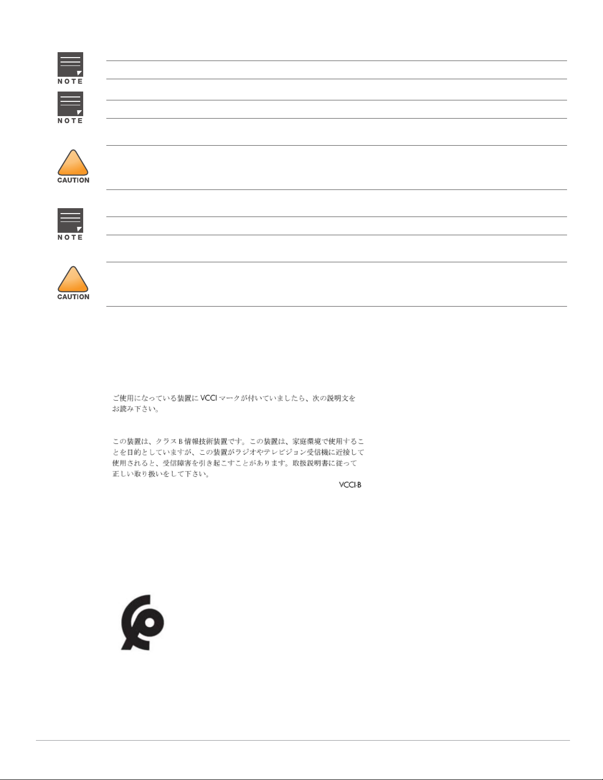
Japan
México
La operación de este equipo está sujeta a las siguientes dos condiciones: (1) es posible que este equipo o
dispositivo no cause interferencia perjudicial y (2) este equipo o dispositivo debeaceptar cualquier interferencia,
incluyendo la que pueda causar su operación no deseada.
Morocco
Aruba Instant On AP22 Access Point | Installation Guide 11
Page 12

Нормативные требования Евразийского Экономического Союза
Russia
HPE Russia: ООО "Хьюлетт Паккард Энтерпрайз" Российская Федерация, 125171, г. Москва, Ленинградское
шоссе, 16А, стр.3, Телефон: +7 499 403 4248 Факс: +7 499 403 4677
'HPE Kazakhstan': TOO «Хьюлетт-Паккард (К)», Республика Казахстан, 050040, г. Алматы, Бостандыкский
район, проспект Аль-Фараби, 77/7, Телефон/факс: + 7 727 355 35 50
Kazakhstan
ЖШС "Хьюлетт Паккард Энтерпрайз" Ресей Федерациясы, 125171, Мәскеу, Ленинград тас жолы, 16A блок
3, Телефон: +7 499 403 4248 Факс: +7 499 403 4677
ЖШС «Хьюлетт-Паккард (К)», Қазақстан Республикасы, 050040, Алматы к., Бостандык ауданы, Әл-Фараби
даңғ ылы, 77/7, Телефон/факс: +7 (727) 355 35 50
Taiwan
第十二條
經型式認證合格之低功率射頻電機,非經許可,公司,商號或使用者均不得擅自變更頻率、加大功率或變更原設計之特性及功能。
第十四條
低功率射頻電機之使用不得影響飛航安全及干擾合法通信;經發現有干擾現象時,應立即停用,並改善至無干擾時方得繼續使用。
前項合法通信,指依電信法規定作業之無線電通信。 低功率射頻電機須忍受合法通信或工業、科學及醫療用電波輻射性電機設備之干
擾。
1. 應避免影響附近雷達系統之操作。
2. 高增益指向性天線只得應用於固定式點對點系統
3. 電磁波暴露量 MPE 標準值 1 mW/cm2, 送測產品實測值為 : 0.18mW/cm2
Ukraine
Hereby, Hewlett Packard Enterprise Company declares that the radio equipment type APIN0505 is in compliance
with Ukrainian Technical Regulation on Radio Equipment, approved by resolution of the CABINET OF MINISTERS
OF UKRAINE dated May 24, 2017, No. 355. The full text of the UA declaration of conformity is available at the
following internet address:
Х’ЮЛЕТТ ПАКАРД ЕНТЕРПРАЗ, 6280 АМЕРИКА ЦЕНТР Д-Р, САН-ХОСЕ, КАЛІФОРНІЯ 95002, США
https://certificates.ext.hpe.com/public/certificates.html
12 Aruba Instant On AP22 Access Point | Installation Guide
Page 13

Contact Aruba
Main Site https://www.ArubaInstantOn.com
Support Site https://www.ArubaInstantOn.com/contact-support/
Aruba Instant On Community https://community.ArubaInstantOn.com
North America Telephone 1-800-943-4526
1-408-754-1200
International Telephone
https://www.ArubaInstantOn.com/contact-support/
Copyright
© Copyright 2020 Hewlett Packard Enterprise Development LP
Open Source Code
This product includes code licensed under the GNU General Public License, the GNU Lesser General Public
License, and/or certain other open source licenses. A complete machine-readable copy of the source code
corresponding to such code is available upon request. This offer is valid to anyone in receipt of this information
and shall expire three years following the date of the final distribution of this product version by Hewlett Packard
Enterprise Company. To obtain such source code, send a check or money order in the amount of US $10.00 to:
Hewlett Packard Enterprise Company
Attn: General Counsel
6280 America Center Drive
San Jose, CA 95002
USA
Warranty
This hardware product is protected by an Aruba warranty. For details, visit
https://www.ArubaInstantOn.com/docs.
Aruba Instant On AP22 Access Point | Installation Guide 13
 Loading...