

Page 1

AGH41B
OPERATION MANUAL
APPLIANCES
FOR LIVING
Page 2

Congratulations, you are now the proud owner of an ARTUSI cooking appliance. Thank you for purchasing ARTUSI
and welcome to the ARTUSI Family.
This instruction manual has been specially created to inform you of the full range of features your ARTUSI appliance
has to offer and serves as an introduction to getting the very best out of your ARTUSI appliance.
We present detailed information on each of the features your ARTUSI appliance consists of. Once you have read
this section you will be able to choose the most appropriate settings for your appliance when cooking different
types of food.
We ask you to read the instructions in this booklet very carefully as this will allow you to get the best results from
using your appliance. KEEP THE DOCUMENTATION OF THIS PRODUCT FOR FUTURE REFERENCE.
TO REGISTER YOUR PRODUCT WITH ARTUSI, PLEASE FILL OUT THE WARRANTY CARD AT THE END OF
THIS BOOKLET AND POST IT TO: REPLY PAID 83617
LEICHHARDT NSW 2040
Dear Artusi Customer, please read this user manual carefully before using the product and, keep it permanently at
your disposal.
Note: This user manual is prepared for more than one model. Some of the features specified in this Manual may not
be available on your appliance.
All our appliances are only for domestic use, not for commercial use. Products marked with (*) are optional.
“THIS APPLIANCE SHALL BE INSTALLED IN ACCORDANCE WITH THE REGULA TIONS FORCE AND ONLY USED
IN A WELL VENTILATED SPACE. READ THE INSTRUCTIONS BEFORE INSTALLING OR USING THIS APPLIANCE”
“Conforms with the WEEE Regulations.”
Page 3

GENERAL NOTICE
We invite you to read this instruction booklet carefully, before installing and using the equipment.
It is very important that you keep this booklet together with the equipment for any future
If this equipment should be sold or transferred to another person, make sure that the new
user receives the booklet, so that they can learn how to operate the appliance and read the
This appliance complies with the following Directives:
EEC 2016/426/UE (Gas) EEC 2014/30/UE (Electromagnetic Compatibility)
EEC 2014/35/UE (Low Voltage) EEC 2004/1935/CE (Contact with foods)
WARNING
- The installation must be carried out by authorised personnel, in conformity with the regulations in force.
- CAUTION: The surface temperature of underbench components exceeds 95°C. To avoid a hazard,
underbench access must be restricted. Refer to the installation instructions.
- This appliance is not intended for use by persons (including children) with reduced physical, sensory or
mental capabilities, or lack of experience and knowledge, unless they have been given supervision or
instruction concerning use of the appliance by a person responsible for their safety.
- Children should be supervised to ensure that they do not play with the appliance.
- Before powering the equipment, check that it is properly adjusted for the type of gas at disposal (see the
“installation” paragraph).
- If the supply cord is damaged it must be replaced by a special cord or assembly available from the
manufacturer or its service agent.
- Before carrying out the maintenance or cleaning the equipment, cut off power supply and allow it cool
down.
- Make sure that air circulates around the gas equipment. Insufficient ventilation produces a lack of oxygen.
- In case of an intense or prolonged use of the equipment, it may be necessary to improve aeration, for
example by opening a window or increasing rangehood venting power, if it exists.
- The products of combustion must be discharged outside through a suction hood or an electric fan (see
the “installation” paragraph).
- For any possible operation or modification, apply to an authorized Technical Assistance Centre and
demand original spare parts.
- NOT FOR USE IN MARINE CRAFT, CARAVANS OR MOBILE HOMES UNLESS EACH BURNER IS
FITTED WITH A FLAME SAFEGUARD.
- DO NOT SPRAY AEROSOLS IN THE VICINITY OF THIS APPLIANCE WHILE IT IS IN OPERATION.
- DO NOT USE OR STORE FLAMMABLE MATERIALS IN OR NEAR THIS APPLIANCE.
- DO NOT PLACE ARTICLES ON OR AGAINST THIS APPLIANCE.
- DO NOT MODIFY THIS APPLIANCE.
- Not suitable for use with aftermarket lids or covers.
- REMOVE all transit material before installation and use.
consultation.
corresponding notice.
This is a Class 3 appliance.
Servicing shall be carried out only by authorised personnel.
The product label, with the serial number, is fixed to the underside of hob.
An additional label should be adhered to adjacent cabinetry for easy access- refer installation
instructions.
The manufacturer refuses all responsibility for possible damages to things or people, resulting
from incorrect installation or from an improper, incorrect or unreasonable use of this equipment.
2
Page 4
GENERAL NOTICE
CUSTOMER SERVICE
Before calling the customer service:
In case of failure of the plan we raccommend:
- check the correct insertion of the plug into the wall socket;
- check that the gas supply is regular.
If you do not locate the cause of the malfunction:
- switch the appliance of and call your service.
INSTRUCTIONS FOR THE USER
IT IS NECESSARY THAT ALL THE OPERATIONS REGARDING THE INSTALLATION, ADJUSTMENT
AND ADAPTATION TO THE TYPE OF GAS AVAILABLE ARE CARRIED OUT BY QUALIFIED
PERSONNEL, IN CONFORMITY WITH THE REGULATIONS IN FORCE.
THE SPECIFIC INSTRUCTIONS ARE DESCRIBED IN THE BOOKLET SECTION
INTENDED FOR THE INSTALLER
The symbols silk-screen printed on the side of the
knob indicate the correspondence between the
knob and the burner.
Automatic start-up with valves
Turn the correspo nding kno b anticlockwise up
to the maximum position (large flame, fig.1) and
press the knob.
Once the burner has been started up, keep the
knob pressed for about 6 seconds.
Using the burners
In order to obtain the maximum yield without
waste of gas, it is important that the diameter of
the pot is suitable for the burner potential (see the
following table), so as to avoid that the flame goes
out of the pot bottom (fig.2).
BURNERS
Double
crown
Power (MJ/h)
NG ULPG
28,0 25,0 28 - 30 cm
Ø of
cookware
Use the maximum capacity to quickly make the
liquids reach the boiling temperature, and the
reduced capacity to heat food or maintain boiling.
All of the operating positions must be chosen
between the maximum and the minimum ones,
never between the minimum position and the
closing point.
The gas supply can be interrupted by turning the
knob clockwise up to the closing position.
If there is no power supply, it is possible to light the
burners with matches, setting the knob to the startup point (large flame).
It is important to use cookware with the sizes
specified and ensure the cookware is always
correctly centred over the burner. Using
oversize cookware can potentially cause heat
damage to your benchtop and/or control knobs
which will not be covered under warranty.
3
Page 5
INSTRUCTIONS FOR THE USER
- Notice
- Whe n the equipment is not working, always
check that the knobs are in the closing position
(see fig.1).
- If the flame should blow out accidentally, the safety
valve will automatically stop the gas supply, after
a few seconds. To restore operation, set the
knob to the lighting point (large flame, fig.1).
- While cooking with fat or oil, pay the utmost
attention as these substances can catch fire
when overheated.
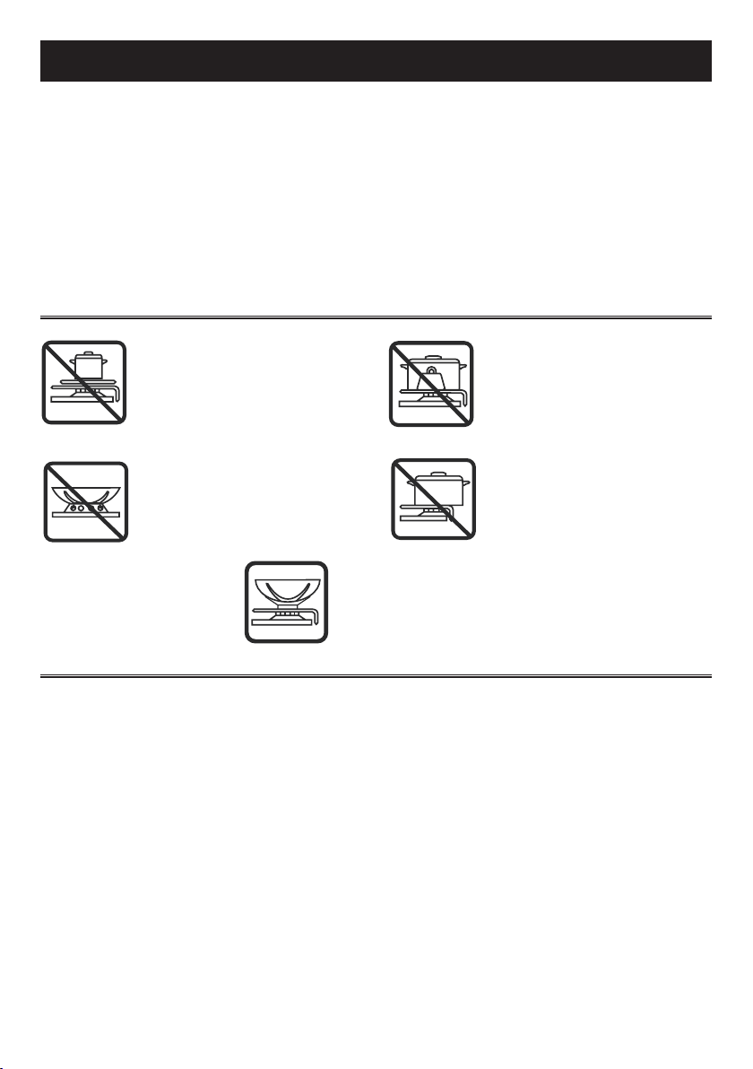
Do not place anything, e.g. flame
tamer, asbestos mat, between pan
and pan support as serious damage to the appliance may result.
Do not remove the pan support
and enclose the burner with a wok
stand as this will concentrate and
deflect the heat onto the hotplate.
Use only a wok support supplied or recommended by the
manufacturer or the appliance.
- Do not use sprays near the appliance in
operation.
- Do not place unstable or deformed pots on the
burner, so as to prevent them from overturning or
overflowing.
- Make sure that pot handles are placed properly.
- When the burner is started up, check that the
flame is regular and, before taking pots away,
always lower the flame or put it out.
D o n ot u se l arg e pots or
heavy weights which can bend
the pan support or deflect
the flame onto the hotplate.
Locate pan centrally over the burner so that it is stable and does
not overhang the appliance.
CLEANING
Before any operation, disconnect the appliance
from the electric grid. Don't use a steam
cleaner for the cleaning the hob.
It is advisable to clean the appliance when it is
cold.
Glass platform and enamelled parts
The glass platform and all of the enamelled parts
must be washed with a sponge and soapy water
or with a light detergent.
Do not use abrasive or corrosive products.
Do not leave substances, such as lemon or tomato
juice, salt water, vinegar, coffee and milk on the
enamelled surfaces for a long time.
Burners and racks
These parts can be removed to make cleaning
easier.
The burners must be washed with a sponge and
soapy water or with a light detergent, wiped well
and placed in their housing perfectly. Make sure
that the flame-dividing ducts are not clogged.
Check that the feeler of the safety valve and the
start-up electrode are always perfectly cleaned, so
as to ensure an optimum operation.
Gas taps
The possible lubrication of the taps must be carried
out by specialized personnel, exclusively.
In case of hardening or malfunctions in the gas
taps, apply to the Customer Service.
4
Page 6
INSTRUCTIONS FOR THE USER
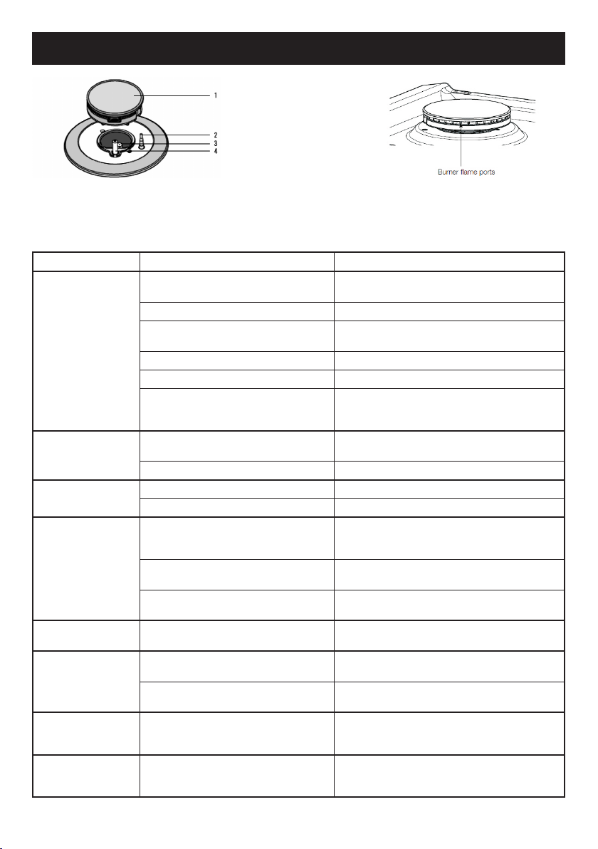
1 Burner 3 Injector
2 Flame safeguard sensor 4 Ignition spark plug
If you have a problem with the cooktop, check the table below. You may be able to solve the problem and this will save
you from paying for a service call. You will have to pay for a service call even in the warranty period if the problem is one
listed below
FAULT POSSIBLE CAUSES REMEDY
Burner will not light
even though the
sparker is working.
No spark is obtained
when control knob is
activated
Flames uneven or
tending to lift
Flames not staying on
when knob released
Low heat, slow
cooking
Benchtop or knobs
overheating
Cooktop stainless
steel discoloured
Outer ring of wok
burner goes out
when set to low
Knob not held down long enough in ‘High’
position for flame safeguard to engage
Gas supply valve turned off Turn on gas supply to appliance
Wrong knob turned Ensure the knob you are turning corresponds to the
Port blockage in ignition area Ensure that ports in ignition area are clean and dry
Ignition spark plugs wet or dirty Dry or clean ignition spark plugs
Injector blocked
El ec tri ci ty su pply is di sc onnec ted o r
switched off"
Ignition spark plugs wet or dirty Dry or clean ignition spark plugs
Flame ports blocked or wet Clean or dry flame ports
Burner incorrectly fitted Ensure this component is fitted correctly
Knob not held down long enough
in ‘High’ position for flame safeguard
(where fitted) to engage
Knob not set between ‘High’ and
‘Low’
Dirt or spillage on flame safeguard
sensor (where fitted)
Incorrect cooking pot or pan being used Refer to table page 3
Incorrect cooking pot or pan used Check table on page 3 for correct pot or pan to be
Pot or pan not located on burner
properly
Pot or pan being is too large Ensure pot sizes used are as per user manual
This is not a failure. This is a function of the
dual wok burner to give a very low power
flame option
Repeat lighting procedure and hold knob down for 6
seconds in ‘High’ position (refer page 3)
burner you want to light
Ensure the injector remains free of any foreign
material. If necessary, use a thin piece of wire to
clear the orifice.
Switch on electricity or check fuses
Repeat lighting procedure and hold knob
down for 6 seconds in ‘High’ position
(refer page 3)
Knob MUST be set between these positions
Clean flame safe guard sensor tip
used
Ensure pot or pan is centrally located
on burner
requirements. Clean with STEEL POWER (available
through spare parts).
No remedy - burner is functioning as intended
If the above points have been checked and there is still a problem with the cooktop, please call the Service Centre.
5
Page 7

INSTRUCTIONS FOR THE INSTALLER
Important notice:
The operations indicated below must be followed by authorised personnel exclusively, in
conformity with the regulations in force.
The manufacturing firm refuses all responsibility for damages to people, animals or things,
resulting from the failure to comply with such provisions.
This appliance shall be installed only by authorised persons and in accordance with the
manufacturer’s installation instructions, local gas fitting regulations, municipal building codes,
electrical wiring regulations, and any other statutory regulations. For Australia and New Zealand
this appliance must be installed by an authorised person in compliance with AS/NZS 5601.1 Gas
installations part 1: general installations, and AS/NZS 5601.2 Gas installations part 2: LP GAS
installations in caravans and boats for nonpropulsive purposes. For outside of Australia/New
Zealand refer to the relevant installation code for gas appliances in your country.
INSTALLATION
The installation kit contains the following:
- 1 natural gas regulator
- 1 elbow
- 1 manifold
- 1 fibre sealing washers
- 4 brackets for assembly
- 4 bracket screws
- 1 pack of cooktop to benchtop seals
- 1 duplicate rating label
Adjacent walls, cupboards and protection for
combustible materials.
Ensure that the appliance is installed in
accordance with clauses 6.2.5 and 6.10.1.1 of AS/
NZS5601.1, or clauses 6.9.1 and 6.9.5 of
AS/NZ S5 601.2 wi th r eg ard t o cl ea rance s
to combustible surfaces and materials, and
clearances to rangehoods and exhaust fans.
Clearance of 200mm from the periphery of
bu rners to vert ic al combu st ible sur fa ces is
requir ed. Clearances to combustibl e surfaces
may be reduced only if combustible surfaces are
protected in accordance with clause 6.10.1.2 of
AS/NZS5601.1, or clause 6.9.2 of AS/NZS5601.2.
For conversion to ULPG
- 1 Universal LPG sticker
- 1 injectors
Additional accessory for cooking with vessel s
diameter 120mm or below
- 1 mini trivet
- 1 wok trivet
Installing the top
The appliance is designed to be embedded into heatresistant benchtop capable of withstanding 95°C.
minimum distance of at least 50 mm from the back
edge of the installed device and 100 mm of the
adjacent side walls.
Rangehoods and exhaust fans* shall be installed
in accordance with the manufacturer’s relevant
instructions. However, in no case shall the
clearance between the highest part of the hob
of the gas cooking appliance and a range hood
be less than 600mm or, for an overhead exhaust
fan, 750mm. (*An exhaust fan is defined as a
mechanical device other than a rangehood for
moving air from one interior space to another, or
to outside of the space) Refer (fig. 4).
Th e eq ui pment must n ot be in st alled n ear
inflammable materials, such as curtains,
cloths,etc. Make a cut out in the benchtop, with
the dimensions indicated in fig.3, respecting a
6
Page 8

INSTRUCTIONS FOR THE INSTALLER
IMPORTANT:
A separation pa nel at least 10m m from the
bottom of the cooktop must be included during
installation to prevent access to the underside
of the appliance. This panel can be made of any
non-combustible rigid material.
If the hob is going to be installed on the top of an
oven, precautions must be taken to guarantee an
installation in accordance with current accident
prevention standards. Pay particular attention to
the position of the electric cable and gas pipe: they
must not touch any hot parts of the oven.
Moreover, if the hob is going to be installed on
the top of a built in oven without forced cooling
ventilation, proper air vents must be installed to
guarantee an adequate ventilation, with the lower
air entering with a cross section of at least 200cm2,
and the higher air exiting with a cross section of at
least 60 cm2.
Fastening the top
Every cook-top is equipped with a special washer.
A set of hooks is also su ppl ied for mounting the
cook-top.
Depending on the type of mounting surface, the
suitable type of mounting hook is supplied (hook A
or hook B).
For the installation proceed as follows:
- Remove all loose components from the top.
- Turn the appliance upside down lay it's edges on
foam packaging blocks to prevent damage to the
ignition spark plugs and lay the seal S along the
external border (fig. 5).
- Introduce and place the cook-top in the hole
made in the piece of furniture, then fasten it
with the screws and fastening brackets supplied
(fig.6).
WARNING: Failure to fix the cooktop to the bench
could result in loosening of the gas connection
through movement of the cooktop and a gas leak
may result.
A duplicate rating label is included with these
instructions. Ensure this is attached to a readily
accessible surface, so that the cooktop can be
easily identied in the case of a service call.
INSTALLATION ROOM
This appliance is not provided with a device for
exhausting the products of combustion.
Therefore, it is necessary to discharge these
outside.
The room where this appliance is installed
must have a natural air inflow, so as to ensure
a regular gas combustion and room ventilation:
the necessary air volume must not be lower than
20m3.
Air must come from permanent openings made on
the room walls that communicate with the outside.
The section of these openings shall correspond to
at least 200 cm2.
OPERATION ON N.G / S.N.G.
Regulator
An appliance regulator is provided. The regulator
must be positioned so that the pressure test nipple
is accessible when the appliance is installed.
Connect the gas supply to the 1/2" B.S.P. internal
thread inlet of the regulator. Refer to page 9 for
connection point position.
Regulators are supplied pre-adjusted and
configured by the component maker for use with
Natural Gas. The appliance installer is not required
to make an adjustment to obtain the correct outlet
pressure setting.
An arrow on the base of the regulator indicates
the direction of gas flow when the inlet and outlet
of the regulator is orientated correctly. When the
regulator has been fitted check for leaks from the
connections with soapy water.
Gas Connection
This appliance is supplied for use with Natural
Gas. However, it can be converted for use with
LPG. Refer to LP conversion chapter.
Supply pipe sizing
The total hourly gas consumption for the appliance
is shown on the data label. The required supply
pressure (i.e. at inlet to appliance regulator) for
each gas type is shown on the data label, and
given in page "TECHNICAL CHARACTERISTIC
TABLES". Use this information in conjunction with
the length of run, number of elbows, tees and
bends, the available service pressure and the
supply requirements of other installed appliances
to determine a suitable pipe size. For assistance
in this matter refer to the appropriate section of the
Installation Code AS/NZS5601.
7
Page 9

INSTRUCTIONS FOR THE INSTALLER
Only install with a hose assembly that complies
with AS/ANZ 1869 (AGA Approved), 10mm ID,
class B or D, no more than 1.2m long and in
accordance with AS/NZS 5601. and in particular
section 4.8. Where a hose assembly is used and
the cooktop is in the installed position, the hose
assembly shall be suitable for connection to a fixed
consumer piping outlet located at a point 800 850mm above the floor and in the region outside
the width of the appliance to a distance of 250mm.
The point of connection to consumer piping must
be accessible with appliance installed.
Elbow positioning
It is possible to reposition the elbow if required by
loosening the locking nut and elbow by using two
spanners. Re-tighten the entire assembly after the
elbow has been repositioned. When fitting elbow to
appliance, ensure that the sealing washer is fitted.
Regulator
An appliance regulator is provided. The regulator
must be positioned so that the pressure test nipple is
accessible when the appliance is installed. Connect
the gas supply to the ½” B.S.P. internal thread inlet
of the regulator. Refer page 10 for connection point
position.
Assembly of Regulator
The assembly of the regulator to the cooktop
manifold is achieved via the elbow union and
sealing washersupplied.
The ½” parallel thread connects to the manifold, and
the sealing washer is placed between the manifold
end and the flat face on the elbow.
The ½” tapered thread connects to the outlet of the
regulator, and is sealed on the thread using
approved thread sealing tape or approved thread
sealing compound.
The inlet of the regulator is a ½” parallel thread and
is connected to consumer piping or hose assembly.
Regulators are supplied pre-adjusted and
configured by the component maker for use with
Natural Gas.
The appliance installer is not required to make an
adjustment to obtain the correct outlet pressure
setting.
An arrow on the base of the regulator indicates the
direction of gas flow when the inlet and outlet of the
regulator is orientated correctly. When the regulator
has been fitted check for leaks from the connections
with soapy water.
Checking the gas supply
1. Check the manometer zero point is correct.
2. Connect the manometer to the cooktop
pressure point. This is located on the
regulator.
3. Turn on the gas supply and electricity and try
to ignite the gas. NOTE! lt will take additional
time to light the gas for the first time as air
needs to be purged from the pipes.
4. With the appliance operating check the outlet
pressure
5. when all burners of the appliance are
operating at maximum,
6. when the smallest burner of the appliance is
operating at minimum.
Under these conditions the outlet pressure should
not vary from the nominal outlet pressure of
1.00kPa by more than ± 0.20kPa
If th e reg ula to r app ear s to no t per for m
satisfactorily, then check the following points:
1. If the outlet pressure is consistently too low
then the inlet pressure may be too low and
adjustment of an upstream regulator may be
needed, or an upstream regulator or valve
with insufficient flow capacity may be present
in the gas supply line. If this is suspected then
it may be necessary to repeat fhe checks
whilst measuring both the inlet and outlet
pressure to determine if the inlet pressure is
in the range 1.13 - 5kPa.
2. Check that the regulafor has been fitted to the
gas supply line in the correct orientation, the
arrow on the base of the body indicates the
direction of gas flow.
Once these checks have been completed, if the
regulator still fails to perform in a satisfactory
manner it should be replaced.
Electrical connection
The appliance is supplied with a standard 10
Amp service cord terminated by a 3-pin plug for
connection to a standard household socket. The
electrical supply is required to power the electronic
ignition system.
NOTE: It will be necessary for servicing purposes
to disconnect the electrical power supply. The
power point should therefore be accessible after
the appliance is installed, as specified in the local
wiring regulations.
TESTING APPLIANCE OPERATION
After installation the installer must fully test the
appliance and ensure it operates correctly before
handing it over to the customer.
8
Page 10

GAS TRANSFORMATIONS AND ADJUSTMENTS
GAS CONVERSIONS AND ADJUSTMENTS
Data Label
A duplicate Data Label is supplied to adhere in an
accessible area next to the appliance.
This appliance is suitable for Natural Gas and
Universal LPG; en sure that the available gas
supply matches the Data Label.
When converting from Natural Gas to Universal
LPG ensure that the NG regulator is removed
and replaced with the Test Point Assembly. An
AGA Approved gas regulator suitable for a supply
pressure of 2.75kPa should be part of the gas
tank supply and the test point pressure should be
adjusted to 2.75kPa.
Replacing double crown burner nozzle
If the equipment is adjusted for a type of gas that is
different from the one available, it is necessary to
replace the burner injectors.
The choice of the injectors to replace must be
made according to the table of the “technical
characteristics” as enclosed.
To replace the nozzle is necessary to remove the
glass or open the panel under the hob (fig.7):
- Remove the nozzle "U" (see picture below) and
insert the new nozzle with the diameter specified
in the "TECHNICAL CARACTERISTIC TABLES".
- Adjust the air by loosening the screw on the door
venturi tube (fig.8). Once loosened the screw
you can proceed to the venturi air adjustment as
explained in the table (dimension "A").
After changing the injector, it is necessary to
eliminate residual natural gas in the system.
To do this you have to turn to the maximum
position then press the knob of each burner and
wait few seconds.
Adjusting the burners
The lowest flame point must always be properly
adjusted and the flame must remain on even if
there is an abrupt shift from the maximum to the
minimum position.
If this is not so, it is necessary to adjust the lowest
flame point as follows:
- start the burner up
- turn the tap up to the minimum position (small
flame)
- remove the knob from the tap rod
- introduce a flat-tip screwdriver in the hole F of
the tap (fig.8) and turn the by-pass screw up to a
proper adjustment of the lowest flame point.
As regards U-LPG gas burners, the by-pass
screw must be tightened completely.
WARNING !!
AL L GAS TR AN SF OR MAT IO NS MUST B E
CARRIED OUT ONLY BY AUTHORISED
PERSONNEL
ADJUSTMENT
AIR
DOUBLE RING
GAS
Natural Gas 8
ULPG 13
SETTING
mm (A)
U
9
Page 11

MAINTENANCE
Maintenance Schedule
No regular maintenance is required for the hotplates except cleaning.
Replacing the power supply cable
If the power supply cable should be replaced, it is necessary to use a cable with a section of 3x0.75mm2,
type H05VV-F or H05RR-F, complying with the regulations in force.
The connection to the terminal board must be effected as shown in fig.11.
brown cable L (phase)
blue cable N (neutral)
green-yellow cable (ground)
11
TECHNICAL CARACTERISTIC - TABLES
1
8
MODEL:
AGH41B
Depth of cooktop casing
from benchtop surface : 130 mm
NG Universal LPG
1 Double ring burner 28.0 MJ/h 25.0 MJ/h
8 Control knob for burner
BURNERS
N° DESCRIPTION KPa 1/100 mm 1/100 mm
DOUBLE
1
CROWN
GAS
Universal LPG 2.75 1,40 60 25,0
Natural 1.00 2,50 Adjust. 28,0
NORMAL
PRESSURE
INJECTOR
DIAMETER
10
TAPE BY
PASS
DIAMETER
NOMINAL
HEAT INPUT
(MJ/h)
Page 12

Maximum
Close
350
Minimum
1 2
495
3 4
5 6
SCREW ADJUSTMENT
TUBE VENTURI
A
7 8
11
Page 13

C
B
A
9 10
WIRING DIAGRAM
MODEL: AGH41B
The manufacturing firm refuses all responsibility for any possible imprecision in this booklet, due to
misprints or clerical errors. It reserves the right to make all the changes that it will consider necessary in
its own products, without affecting the essential characteristics of functionality and safety.
12
Page 14

13
Page 15

FOR SPARE PARTS OR TO FIND THE ADDRESS OF
YOUR NEAREST STATE SPARE PARTS CENTRE IN AUSTRALIA
Distributes by Eurolinx pty Ltd
Street: 48-50 Moore Street, Leichhardt N.S.W 2040
Suburb / City: SYDNEY
State / Country:
Postcode: 2040
Telephone: +1 300 85 64 11
14
Page 16

Warranty Card
Worldwide Appliances Pty Limited
A.B.N. 45868077422
Oce:
48-50 Moore Street, Leichhardt N.S.W 2040
Post:
Locked Bag 3000, Annandale, N.S.W 2038
P: 1300 694 583
WARRANTY REGISTRATION
Your ongoing satisfaction with your artusi
product is important to us. We ask that you
complete the enclosed Warranty Registration
Card and return it to us so that we have a record
of the artusi product purchased by you.
PRIVACY
Worldwide Appliances respects your
privacy and is committed to handling your
personal information in accordance with the
National Privacy Principles and the Privacy
Act 1988 (Cth). A copy of the Worldwide
Appliances Privacy Policy is available at
www.artusi.com.au. Worldwide Appliances will
not disclose any personal information set out
in the Warranty Registration Card (“Personal
Information”) without your consent unless
required by:
1. law;
2. any Worldwide Appliances related company;
3. any service provider which provide services
to artusi or assist artusi in providing services
(including repair and warranty services) to
customers. Our purpose in collecting the
Personal Information is
to keep a record of the artusi product purchased
by you, in order to provide a better warranty
service to you in the unlikely event that there is
a problem with your artusi product. Worldwide
Appliances may contact you at any one or more
of the address, email address or telephone
numbers set out in the Warranty Registration
Card. Please contact artusi on 1300 694
583 should you not wish to be contacted by
Worldwide Appliances.
WARRANTY
1. Warranty
Worldwide Appliances warrants that each artusi
product will remain, for a period of either 12
months or 24 months of warranty. All Warranties
are valid from the original date of purchase, And
warranty claims must be accompanied by the
proof of purchase.
24 months warranty products:
All Built-in Appliances – Limited to Ovens,
Gas, Induction and Electric Cooktops, and All
Rangehoods
Freestanding Cookers - Gas and Electric Models
(900mm Width)
artusi.com.au
Dishwashers - Freestanding, Fully Integrated,
Semi Integrated and built-in
12 months warranty products:
Freestanding Cookers - Gas and Electric Models
in 50cm, 54cm and 60cm Widths
Portable Appliances* – Benchtop Models and
Portable Gas Models
2. What is not Covered by the Warranty.
The Warranty does not apply if an artusi product
is defective by a factor other than a defect arising
in the manufacture of the artusi product, including
but not limited to:
(a) damage through misuse (including failure
to maintain, service or use with proper care),
neglect, accident or ordinary wear and tear
(including deterioration of parts and accessories
and glass breakage);
(b) use for purpose for which the artusi product
was not sold or designed;
(c) use or installation which is not in accordance
with any specied instructions for use or
installation;
(d) use or operation after a defect has occurred or
been discovered;
(e) damage through freight, transportation or
handling in transit (other than when Worldwide
Appliances is responsible);
(f) damage through exposure to chemicals, dusts,
residues, excessive voltage, heat, atmospheric
conditions or other forces or environmental
factors outside the control or Worldwide
Appliances;
(g) repair, modication or tampering by the
purchaser or any person other than Worldwide
Appliances, an employee of Worldwide
Appliances or an authorised artusi service
contractor*;
(h) use of parts, components or accessories
which have not been supplied or specically
approved by artusi.
(i) damage to surface coatings caused by cleaning
or maintenance using products not recommended
in the artusi product handbook provided to the
purchaser upon purchase of the artusi product;
(j) damage to the base of an electric oven due to
items having been placed on the base of the oven
cavity or covering the base, such as aluminium
foil (this impedes the transfer of heat from the
element to the oven cavity and can result in
irreparable damage); or
(k) damages, dents or other cosmetic
imperfections not aecting the performance of the
artusi in respect of an artusi product purchased
as a “factory second” or from display
The Warranty does not extend to light globes
used in artusi products.
3. Domestic Use
Each artusi product is made for domestic use.
This Warranty may not extend to artusi products
used for commercial purposes.
Continued over...
Page 17

Warranty Card continued
artusi.com.au
4. Time for Claim under the Warranty
You must make any claim under this Warranty
within twenty eight (28) days after the occurrence
of an event which gives rise to a claim pursuant
to the Warranty, by booking a service call on the
telephone number below.
5. Proof of Purchase
Customers must retain proof of purchase in order
to be eligible to make a warranty claim in respect
of an artusi product.
6. Claiming under the Warranty
Customers will bear the cost of claiming under
this Warranty unless Worldwide Appliances
determines the expenses are reasonable, in which
case the customer must claim those expenses
by providing written evidence of each expense
to Worldwide Appliances at the address on the
Warranty Registration Card.
7. Statutory Rights
(a) These terms and conditions do not aect your
statutory rights.
(b) The limitations on the Warranty set out in this
document do not exclude or limit the application
of the consumer guarantees set out in the Act or
any other equivalent or corresponding legislation
in the relevant jurisdiction where to do so would:
(i) contravene the law of the relevant jurisdiction;
or
(ii) cause any part of the Warranty to be void.
(c) Worldwide Appliances excludes indirect or
consequential loss of any kind (including, without
limitation, loss of use of the artusi product) and
(other than expressly provided for in these terms
and conditions) subject to all terms,
conditions and warranties implied by custom, the
general law, the Act or other statute.
(d) The liability of Worldwide Appliances to you
Warranty Card tear off
for a breach of any express or non-excludable
implied term, condition or warranty is limited at
the option of Worldwide Appliances to:
(i) replacing or repairing the defective part of the
artusi product;
(ii) paying the cost of replacing or repairing the
defective part of the artusi product;
(iii) replacing the artusi product; or
(iv) paying the cost of replacing the artusi
product.
(e) Our goods come with guarantees that cannot
be excluded under the Australian Consumer
Law. You are entitled to a replacement or refund
for a major failure and for compensation for any
other reasonably foreseeable loss or damage.
You are also entitled to have the goods repaired
or replaced if the goods fail to be of acceptable
quality and the failure does not amount to a
major failure.
8. Defects
Any part of an artusi product deemed to be
defective and replaced by Worldwide Appliances
is the property of Worldwide Appliances.
Worldwide Appliances reserves the right to
inspect and test artusi products in order to
determine the extent of any defect and the
validity of a claim under the Warranty.
*To locate your closest artusi authorised service
agent please contact us on 1300 652 100 or visit
www.artusi.com.au
ALL SERVICE CALLS MUST BE BOOKED
THROUGH AN AUTHORISED DEALER OR
WARRANTY DEPARTMENT ON 1300 652 100
OR stokesaps.com.au/artusi-service
01032014
WARRANTY REGISTRATION CARD
01052013
Last Name: First Name:
Address:
State: Postcode: Email:
Home Phone: Mobile:
Purchase Date: / / (Please attach proof of purchase to validate warranty)
MODEL NUMBER
1
2
3
4
Please complete and send to ARTUSI at: REPLY PAID 83617
LEICHHARDT NSW 2040
SERIAL NUMBER
(if you cannot locate the serial number please call ARTUSI on 1300 694 583)
01032014
4
Page 18

Page 19

DISCLAIMER
Worldwide Appliances PTY LTD, trading as ARTUSI, is continually seeking ways to improve the design specifications, aesthetics and production
techniques of its products. As a result alterations to our products and designs take place continually. Whilst every effort is made to produce
information and literature that is up to date, this brochure should not be regarded as an infallible guide to the current specifications, nor does it
constitute an offer for the sale of any particular product. Product dimensions indicated in our literature is indicative only. Actual product only
should be used to define dimension cutouts. Distributors, and retailers are not agents of ARTUSI and are not authorised to bind ARTUSI by any
express or implied undertaking or representation.
ARTUSI OFFICES ARE OPEN DAILY FROM 9AM–5PM AND SATURDAYS 10AM–4PM
NSW & ACT (HEAD OFFICE)
48-50 MOORE STREET
LEICHHARDT
F 02 8569 4699
P: 13 00 6 49 5 83
VIC, TAS & SA
1211 TOORAK ROAD
CAMBERWELL
F 03 9809 2155
QLD
1/42 CAVENDISH ROAD
COORPAROO
F 07 3397 0850
WA & NT
UNIT 10/55 HOWE STREET
OSBORNE PARK
F 08 9201 9188
NZ
PO BOX 11.160
SOCKBURN CHRISTCHURCH
F 03 344 5906
ARTUSI.COM.AU
 Loading...