

Page 1
User Manual
Motorola 2247-N8
DSL W
i-Fi Gateway
SAVE THESE INSTRUCTIONS
Page 2

Contents
Motorola 2247-N8 DSL Wi-Fi Gateway User Guide
CONTENTS . . . . . . . . . . . . . . . . . . . . . . . . . . . . . . . . . . . . . . . . . 2
OPYRIGHTS . . . . . . . . . . . . . . . . . . . . . . . . . . . . . . . . . . . . . . . 4
C
AFETY INFORMATION. . . . . . . . . . . . . . . . . . . . . . . . . . . . . . . . . 4
S
ETUP AND INSTALLATION . . . . . . . . . . . . . . . . . . . . . . . . . . . . . . 5
S
Before you Begin . . . . . . . . . . . . . . . . . . . . . . . . . . . . . . . . . . . . 5
Connecting the Gateway . . . . . . . . . . . . . . . . . . . . . . . . . . . . . . 6
Wireless (Wi-Fi) Network Setup . . . . . . . . . . . . . . . . . . . . . . . . 8
Connecting to the Web Management Interface . . . . . . . . . .9
Wired (Ethernet) Network Setup . . . . . . . . . . . . . . . . . . . . . . . 10
Connecting to the Web Management Interface . . . . . . . . . .11
ADVANCED CONFIGURATION PROCEDURES . . . . . . . . . . . . . . . . . 13
DVANCED CONFIGURATIONS . . . . . . . . . . . . . . . . . . . . . . . . . . 16
A
Links Bar . . . . . . . . . . . . . . . . . . . . . . . . . . . . . . . . . . . . . . . . . . . 16
Help . . . . . . . . . . . . . . . . . . . . . . . . . . . . . . . . . . . . . . . . . . . . . . . 17
System . . . . . . . . . . . . . . . . . . . . . . . . . . . . . . . . . . . . . . . . . . . . 27
Status . . . . . . . . . . . . . . . . . . . . . . . . . . . . . . . . . . . . . . . . . . . . . 28
Access Code. . . . . . . . . . . . . . . . . . . . . . . . . . . . . . . . . . . . . . . . 29
Upgrade . . . . . . . . . . . . . . . . . . . . . . . . . . . . . . . . . . . . . . . . . . . 31
Restart . . . . . . . . . . . . . . . . . . . . . . . . . . . . . . . . . . . . . . . . . . . . 33
Reset . . . . . . . . . . . . . . . . . . . . . . . . . . . . . . . . . . . . . . . . . . . . . 34
Remote Access . . . . . . . . . . . . . . . . . . . . . . . . . . . . . . . . . . . . . 35
Restricted Hosts . . . . . . . . . . . . . . . . . . . . . . . . . . . . . . . . . . . . 38
Timezone . . . . . . . . . . . . . . . . . . . . . . . . . . . . . . . . . . . . . . . . . . 41
Broadband . . . . . . . . . . . . . . . . . . . . . . . . . . . . . . . . . . . . . . . . . 42
Status . . . . . . . . . . . . . . . . . . . . . . . . . . . . . . . . . . . . . . . . . . . . . 43
Configure . . . . . . . . . . . . . . . . . . . . . . . . . . . . . . . . . . . . . . . . . . 46
Dynamic DNS. . . . . . . . . . . . . . . . . . . . . . . . . . . . . . . . . . . . . . . 50
IPv6. . . . . . . . . . . . . . . . . . . . . . . . . . . . . . . . . . . . . . . . . . . . . . . 52
Home Network. . . . . . . . . . . . . . . . . . . . . . . . . . . . . . . . . . . . . . 59
Status . . . . . . . . . . . . . . . . . . . . . . . . . . . . . . . . . . . . . . . . . . . . . 60
Configure . . . . . . . . . . . . . . . . . . . . . . . . . . . . . . . . . . . . . . . . . . 63
Subnets & DHCP . . . . . . . . . . . . . . . . . . . . . . . . . . . . . . . . . . . .64
USB File System. . . . . . . . . . . . . . . . . . . . . . . . . . . . . . . . . . . . . 68
Wireless . . . . . . . . . . . . . . . . . . . . . . . . . . . . . . . . . . . . . . . . . . . 70
Status . . . . . . . . . . . . . . . . . . . . . . . . . . . . . . . . . . . . . . . . . . . . . 71
Configure . . . . . . . . . . . . . . . . . . . . . . . . . . . . . . . . . . . . . . . . . . 74
MAC Filtering. . . . . . . . . . . . . . . . . . . . . . . . . . . . . . . . . . . . . . . 80
Channel Scan. . . . . . . . . . . . . . . . . . . . . . . . . . . . . . . . . . . . . . . 82
Basics. . . . . . . . . . . . . . . . . . . . . . . . . . . . . . . . . . . . . . . . . . . . . . 17
Home . . . . . . . . . . . . . . . . . . . . . . . . . . . . . . . . . . . . . . . . . . . . .18
Quickstart. . . . . . . . . . . . . . . . . . . . . . . . . . . . . . . . . . . . . . . . . .20
Device List . . . . . . . . . . . . . . . . . . . . . . . . . . . . . . . . . . . . . . . . .23
Alias . . . . . . . . . . . . . . . . . . . . . . . . . . . . . . . . . . . . . . . . . . . . . .25
Firewall . . . . . . . . . . . . . . . . . . . . . . . . . . . . . . . . . . . . . . . . . . . . 83
Status . . . . . . . . . . . . . . . . . . . . . . . . . . . . . . . . . . . . . . . . . . . . . 84
Firewall . . . . . . . . . . . . . . . . . . . . . . . . . . . . . . . . . . . . . . . . . . . 85
NAT/Gaming . . . . . . . . . . . . . . . . . . . . . . . . . . . . . . . . . . . . . . . 86
Packet Filter. . . . . . . . . . . . . . . . . . . . . . . . . . . . . . . . . . . . . . . . 89
IP Passthrough . . . . . . . . . . . . . . . . . . . . . . . . . . . . . . . . . . . . . 94
DoS Protection . . . . . . . . . . . . . . . . . . . . . . . . . . . . . . . . . . . . . 97
Diagnostics . . . . . . . . . . . . . . . . . . . . . . . . . . . . . . . . . . . . . . . . . 99
Troubleshoot. . . . . . . . . . . . . . . . . . . . . . . . . . . . . . . . . . . . . . . 100
Logs . . . . . . . . . . . . . . . . . . . . . . . . . . . . . . . . . . . . . . . . . . . . . . 103
Please visit www.motorola.com/us/support for FAQs and additional product documentation. 2
Page 3

FREQUENTLY ASKED QUESTIONS - AND ANSWERS (FAQS) . . . . . 105
ASIC TROUBLESHOOTING . . . . . . . . . . . . . . . . . . . . . . . . . . . . 107
B
Condition Indicators (LEDs) . . . . . . . . . . . . . . . . . . . . . . . . . . . . 107
Troubleshooting LED Conditions. . . . . . . . . . . . . . . . . . . . . . . . 109
Adding Devices to the Wireless Network. . . . . . . . . . . . . . . . . 110
Microsoft Windows 8 . . . . . . . . . . . . . . . . . . . . . . . . . . . . . . . .110
Microsoft Windows 7 . . . . . . . . . . . . . . . . . . . . . . . . . . . . . . . .111
Microsoft Windows XP . . . . . . . . . . . . . . . . . . . . . . . . . . . . . . .113
Mac OS X Releases . . . . . . . . . . . . . . . . . . . . . . . . . . . . . . . . . .115
Configuring Client Devices. . . . . . . . . . . . . . . . . . . . . . . . . . . . . 116
Microsoft Windows 8 . . . . . . . . . . . . . . . . . . . . . . . . . . . . . . . .117
Microsoft Windows 7 and Vista. . . . . . . . . . . . . . . . . . . . . . . .119
Microsoft Windows XP . . . . . . . . . . . . . . . . . . . . . . . . . . . . . . .121
Mac OS X . . . . . . . . . . . . . . . . . . . . . . . . . . . . . . . . . . . . . . . . . .122
Access Information . . . . . . . . . . . . . . . . . . . . . . . . . . . . . . . . . . 124
Motorola 2247-N8 DSL Wi-Fi Gateway User Guide
SUPPORT . . . . . . . . . . . . . . . . . . . . . . . . . . . . . . . . . . . . . . . . 125
ARING FOR THE ENVIRONMENT BY RECYCLING . . . . . . . . . . . . . 126
C
Recycling your Motorola Equipment. . . . . . . . . . . . . . . . . . . .126
Genbrug af dit Motorola-udstyr . . . . . . . . . . . . . . . . . . . . . . .126
Recycling bei Geräten von Motorola. . . . . . . . . . . . . . . . . . . .126
Reciclaje de su equipo Motorola . . . . . . . . . . . . . . . . . . . . . . .126
Recyclage de votre équipement Motorola . . . . . . . . . . . . . . .127
Uw Motorola-materiaal recycleren. . . . . . . . . . . . . . . . . . . . .127
Recykling posiadanego sprz´tu Motorola . . . . . . . . . . . . . . . .127
Reciclagem do seu equipamento Motorola . . . . . . . . . . . . . .127
Återvinning av din Motorola-utrustning . . . . . . . . . . . . . . . . .128
INDEX . . . . . . . . . . . . . . . . . . . . . . . . . . . . . . . . . . . . . . . . . . 129
Please visit www.motorola.com/us/support for FAQs and additional product documentation. 3
Page 4

Motorola 2247-N8 DSL Wi-Fi Gateway User Guide
Copyrights
©2013 Motorola Mobility LLC All rights reserved. MOTOROLA, and the Stylized M Logo are trademarks or registered trademarks of Motorola Trademark Holdings, LLC. All other trademarks are
the property of their respective owners. No part of this publication may be reproduced in any
form or by any means or used to make any derivative work (such as translation, transformation, or
adaptation) without written permission from Motorola Mobility LLC. Motorola Mobility reserves
the right to revise this publication and to make changes in content from time to time without obligation on the part of Motorola Mobility to provide notification of such revision or change. Motorola Mobility provides this guide without warranty of any kind, implied or expressed, including, but
not limited to, the implied warranties of merchantability and fitness for a particular purpose.
Motorola Mobility may make improvements or changes in the product(s) described in this manual
at any time.
EXCEPT AS INDICATED IN THE APPLICABLE SYSTEM PURCHASE AGREEMENT, THE SYSTEM, DOCUMENTATION AND SERVICES ARE PROVIDED “AS IS”, AS AVAILABLE, WITHOUT WARRANTY OF ANY
KIND. MOTOROLA MOBILITY LLC DOES NOT WARRANT THAT THE SYSTEM WILL MEET CUSTOMER'S REQUIREMENTS, OR THAT THEIR OPERATION WILL BE UNINTERRUPTED OR ERRORFREE, OR THAT ANY ERRORS CAN OR WILL BE FIXED. MOTOROLA MOBILITY LLC HEREBY DISCLAIMS ALL OTHER WARRANTIES, EXPRESS OR IMPLIED, ORAL OR WRITTEN, WITH RESPECT TO
THE SYSTEM AND SERVICES INCLUDING, WITHOUT LIMITATION, ALL IMPLIED WARRANTIES OF
TITLE, NON-INFRINGEMENT, INTEGRATION, MERCHANTABILITY OR FITNESS FOR ANY PARTICULAR
PURPOSE AND ALL WARRANTIES ARISING FROM ANY COURSE OF DEALING OR PERFORMANCE OR
USAGE OF TRADE.
EXCEPT AS INDICATED IN THE APPLICABLE SYSTEM PURCHASE AGREEMENT, MOTOROLA MOBILITY LLC SHALL NOT BE LIABLE CONCERNING THE SYSTEM OR SUBJECT MATTER OF THIS DOCUMENTATION, REGARDLESS OF THE FORM OF ANY CLAIM OR ACTION (WHETHER IN CONTRACT,
NEGLIGENCE, STRICT LIABILITY OR OTHERWISE), FOR ANY (A) MATTER BEYOND ITS REASONABLE
CONTROL, (B) LOSS OR INACCURACY OF DATA, LOSS OR INTERRUPTION OF USE, OR COST OF PROCURING SUBSTITUTE TECHNOLOGY, GOODS OR SERVICES, (C) INDIRECT, PUNITIVE, INCIDENTAL,
RELIANCE, SPECIAL, EXEMPLARY OR CONSEQUENTIAL DAMAGES INCLUDING, BUT NOT LIMITED
TO, LOSS OF BUSINESS, REVENUES, PROFITS OR GOODWILL, OR (D) DIRECT DAMAGES, IN THE
AGGREGATE, IN EXCESS OF THE FEES PAID TO IT HEREUNDER FOR THE SYSTEM OR SERVICE GIVING RISE TO SUCH DAMAGES DURING THE 12-MONTH PERIOD PRIOR TO THE DATE THE CAUSE OF
ACTION AROSE, EVEN IF COMPANY HAS BEEN ADVISED OF THE POSSIBILITY OF SUCH DAMAGES.
THESE LIMITATIONS ARE INDEPENDENT FROM ALL OTHER PROVISIONS OF THIS AGREEMENT AND
SHALL APPLY NOTWITHSTANDING THE FAILURE OF ANY REMEDY PROVIDED HEREIN.
Safety Information
CAUTION: Depending on the power supply provided with this product,
one of the following serves as the mains power disconnect: power supply
cord plug, or appliance coupler. It is important that the direct plug-in
power supply, the power socket-outlet, or the appliance coupler be
readily accessible.
TELECOMMUNICATION Safety: When using your telephone equip-
ment, follow these basic safety precautions to reduce the risk of fire,
electric shock, and injury:
Do not use this product near water, for example, near a bathtub,
or sink, in a wet basement, or near a swimming pool.
Avoid using a telephone (other than a cordless type) during an
electrical storm. There may be a remote risk of electrical shock
from lightning.
Do not use the telephone to report a gas leak in the vicinity of
the leak.
PRODUCT VENTILATION: The Motorola 2247-N8 DSL Wi-Fi Gateway is
intended for use in a consumer's home.
Ambient temperatures should not exceed 104°F (40°C).
Do not use in locations exposed to outside heat radiation or
trapping of its own heat.
At least one inch of clearance should be maintained on all sides
except the bottom when properly installed. The 2247-N8 Gateway should not be placed inside tightly enclosed spaces unless
proper ventilation is provided.
All Motorola Mobility LLC products are furnished under a license agreement included with the
product. If you are unable to locate a copy of the license agreement, please contact Motorola
Mobility LLC.
Motorola Mobility Part Number: 579442-003-00
Please visit www.motorola.com/us/support for FAQs and additional product documentation. 4
Page 5
Setup and Installation
Motorola 2247-N8 DSL Wi-Fi Gateway User Guide
Thank you for selecting the Motorola 2247-N8 DSL Wi-Fi Gateway. This guide
will help you install the 2247-N8, connect computers and other devices to it
using the 2247-N8’s wired (Ethernet) or wireless networking capabilities, and
connect to your existing DSL provider for Internet access.
TIP: For rapid installation, configuration, and set up of wireless networking,
use the instructions on the included Quick Start Guide.
Advanced configuration instructions and basic troubleshooting are also provided in this User Guide. If you need additional information about the
2247-N8, or have configuration and use questions, go to
www.motorola.com/us/support.
Before you Begin
IMPORTANT: You must have an existing DSL connection installed before
starting installation of the 2247-N8! You will also need the information below
from your DSL service provider:
PPP or PPPoE user name and password - This may be the e-mail user
name and password from your DSL provider’s service, or it may be a
customer identification name and password. If you are unsure, contact your DSL provider.
VPI/VCI numbers used with your DSL service - In most cases the
2247-N8 will automatically detect this information. If you need to
enter it, refer to “How to configure a Point to Point Protocol (PPPoE
or PPPoA) broadband connection:” on page 47 of this User Guide.
Quick Start Guide
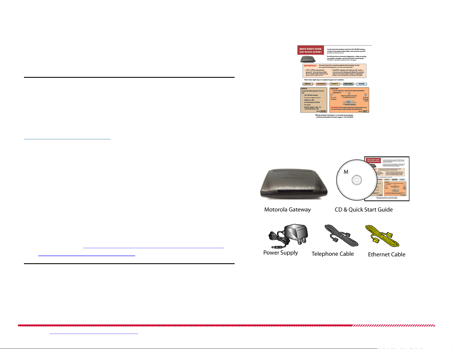
Package Contents
Note: Check the contents of the box to make sure you have all the items
shown to the right:
BEFORE RETURNING THIS PRODUCT TO THE STORE for any reason, call
Motorola Broadband Technical Support at 1-877-466-8646.
Please visit www.motorola.com/us/support for FAQs and additional product documentation. 5
Page 6
Connecting the Gateway
$3,*ACK
!#/UTLET
.
O
T
H
I
N
G
B
L
O
C
K
I
N
G
V
E
N
T
S
#
L
E
A
R
A
R
E
A
M
O
R
E
T
H
A
N
I
N
C
H
$3,*ACK
.O$3,&ILTER
$3,0ORT
Motorola 2247-N8 DSL Wi-Fi Gateway User Guide
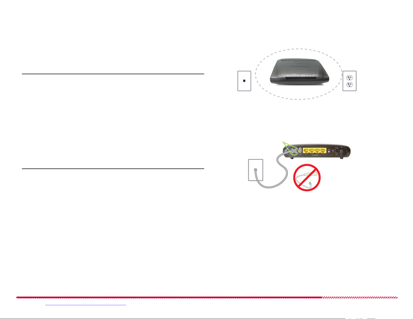
1. Decide on a location for the 2247-N8.
Put the 2247-N8 near an AC wall outlet (the power source) and a
phone jack activated for DSL, in a cool location where none of the
2247-N8’s vents will be blocked.
Caution: If the location is too hot or the vents are blocked, the high
temperature could cause the 2247-N8 to malfunction.
2. Connect the 2247-N8 to the DSL service:
Plug the telephone cable (included gray cord) into the gray DSL
port on the back of the 2247-N8.
Plug the other end of the telephone cable into a phone jack acti-
vated for DSL.
Note: If your DSL service uses line filters, do not plug the telephone
cable from the 2247-N8 into a line filter.
Location Guidelines
Connecting to DSL Service
Please visit www.motorola.com/us/support for FAQs and additional product documentation. 6
Page 7

Connecting the Gateway (Continued)
0OWERJACK
!#POWERCORD
0OWERSWITCH
Motorola 2247-N8 DSL Wi-Fi Gateway User Guide
3. Power the 2247-N8.
Connect the power supply to the power jack on the back panel
of the 2247-N8.
Plug the power supply into an electrical outlet.
Turn on the Power switch.
The Power light (on the front of the 2247-N8) should light solid
green.
4. Wait for the DSL light on the front of the 2247-N8 to turn solid green
(steady and not blinking). This may take up to five minutes.
To connect a wireless device, continue with “Wireless (Wi-Fi) Network
Setup” on page 8. To connect a wired device, continue with “Wired
(Ethernet) Network Setup” on page 10.
Connecting Power
Please visit www.motorola.com/us/support for FAQs and additional product documentation. 7
Page 8
Wireless (Wi-Fi) Network Setup
Windows 7/XP/Vista Windows 8 Mac OS X
The 2247-N8 Wi-Fi Gateway has a default network "name," or SSID (service set identifier). The 2247-N8 broadcasts this unique network name
so that wireless computers and other devices can detect it. The default
network name is “moto” followed by the last four digits of the 2247-N8’s
serial number.
With the 2247-N8 installed and on, use the following steps to add
devices to the wireless network.
Motorola 2247-N8 DSL Wi-Fi Gateway User Guide
TIP: Because your computer detects the strongest wireless networks
first, position it close (within 10 feet) to the 2247-N8, if you can, to ensure
that you are connecting to your 2247-N8.
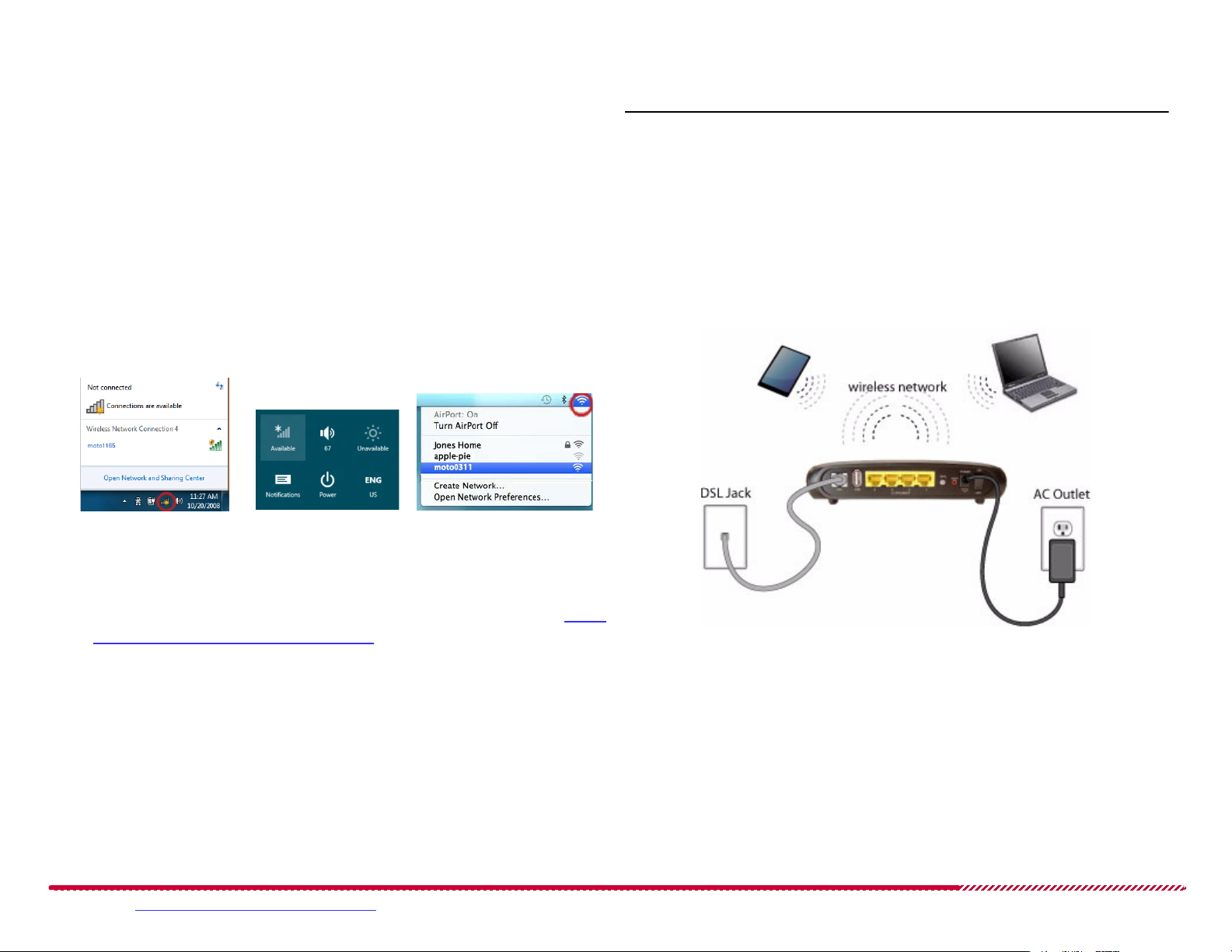
1. Connect your primary computer to the 2247-N8 wireless network.
Click the wireless tray icon, open the wireless settings panel, or click
the AirPort menu (depending on your operating system).
2. Find the network ID for your 2247-N8 in the wireless networks list
and connect your computer to the network. If you have difficulty
connecting to the network, refer to the detailed instructions in “Add-
ing Devices to the Wireless Network” on page 110.
3. When prompted for the Wi-Fi network access key, type the numbers
printed on the “Device Access Code” sticker on the bottom of the
2247-N8 as your key or password.
2247-N8 Wireless Installation
Please visit www.motorola.com/us/support for FAQs and additional product documentation. 8
Page 9
Wireless (Wi-Fi) Network Setup (Continued)
Connecting to the Web Management Interface
Motorola 2247-N8 DSL Wi-Fi Gateway User Guide
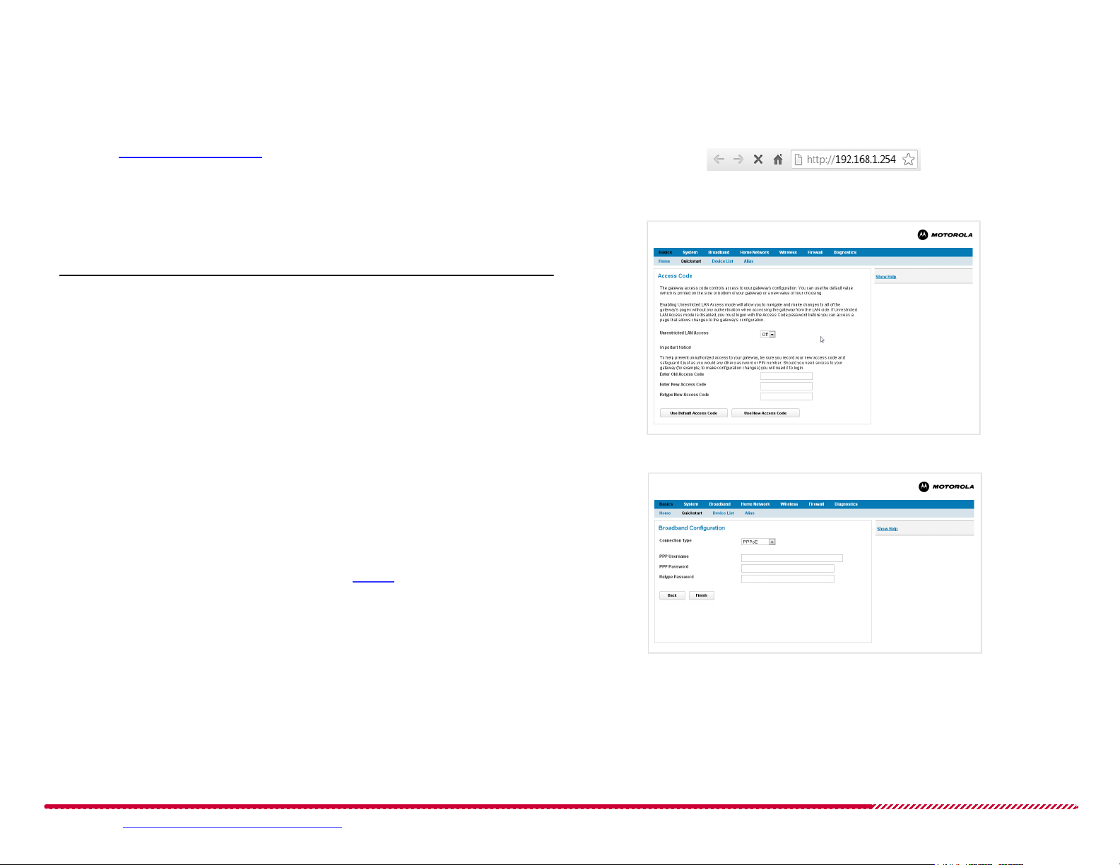
4. Once you are connected to the 2247-N8, open a Web browser and
type http://192.168.1.254 into the address bar. Press ENTER.
An Access Code page appears.
5. At the Access Code page follow the on-screen instructions to
decide if you want unrestricted LAN access or password-protected
access.
Note: if you use password protection, your user name is “admin”.
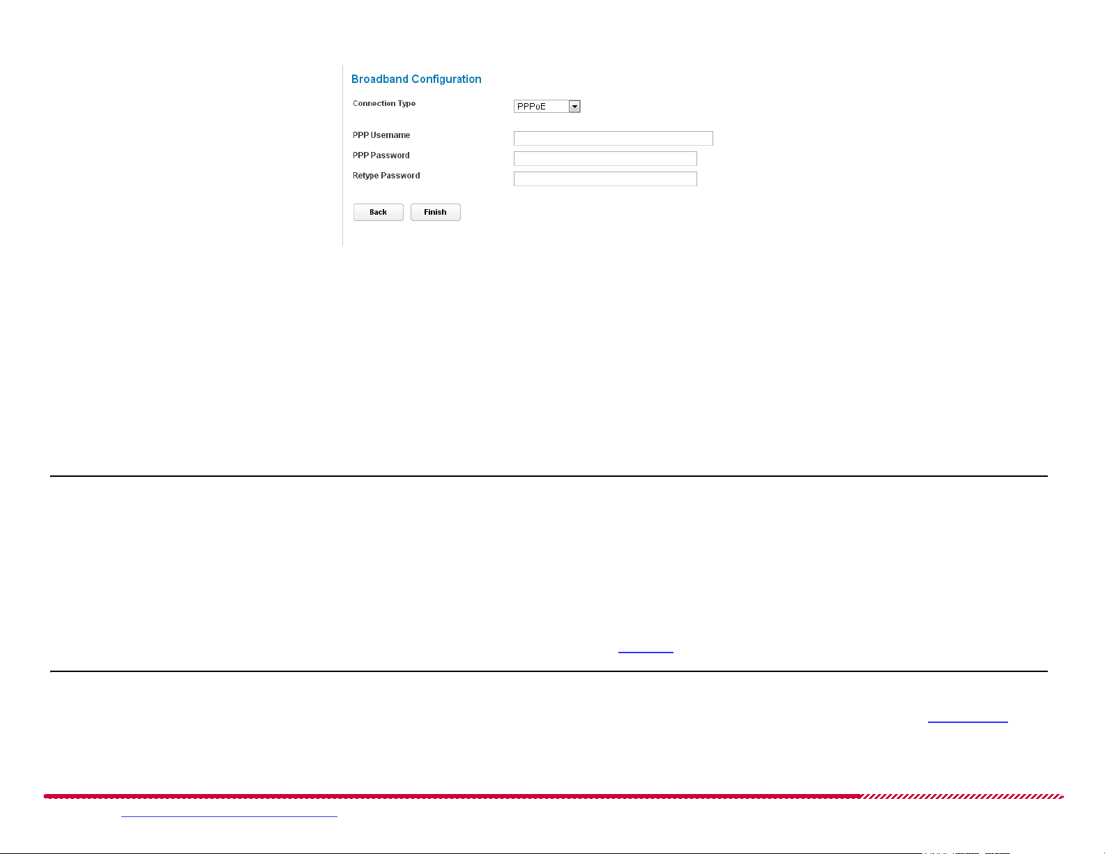
After you log in to the 2247-N8, the Broadband Configuration page
will appear.
6. Click the Connection Type pull-down menu and click the type of
ADSL service that your service provider is providing, then perform the
following steps based on that connection type:
PPPoE or PPPoA: Enter your PPP user name and password, pro-
vided to you by your DSL service provider. Remember, you may
need to call your DSL provider for this information.
DHCP Client: Proceed immediately to step 7.
2247-N8 Web Management Interface Address
Quickstart Access Code Page
QuickStart Broadband Configuration Page
Please visit www.motorola.com/us/support for FAQs and additional product documentation. 9
Page 10

Wireless (Wi-Fi) Network Setup (Continued)
7. Click the Finish button.
The 2247-N8 shows a progress bar as it waits for the DSL network
connection to initialize. If the DSL network connection cannot initialize, you may be prompted to re-enter your PPP user name and password.
After the waiting period, the browser updates to show the Connec-
tion Information
connection to the provider DSL network was successful. Seeing the
current network status may require refreshing the browser window.
Close any open browser windows once the broadband network connection is active.
8. Open a new Web browser and enjoy your Internet access through the
Motorola 2247-N8 DSL Wi-Fi Gateway!
page. If the broadband status is listed as “Up”, t he
Motorola 2247-N8 DSL Wi-Fi Gateway User Guide
TIP: If you are having trouble connecting, enter your information again
and make sure the Caps Lock key on your computer is not on. If your service provider network uses another broadband connection method (static
IP assignment or DHCP), or if the automatic detection of DSL settings did
not succeed, you may need to use the advanced configuration options:
“How to configure a Point to Point Protocol (PPPoE or
PPPoA) broadband connection:” on page 47.
“How to configure a DHCP Client assignment broadband
connection:” on page 48.
“How to configure an assigned Static IP broadband connec-
tion:” on page 49.
If you are still having trouble, go to “Frequently Asked Questions - and
Answers (FAQs)” on page 105 or “Basic Troubleshooting” on page 107.
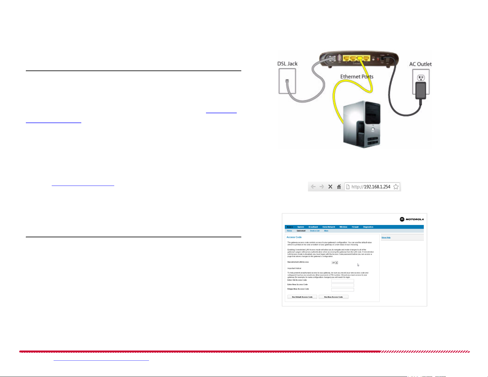
Wired (Ethernet) Network Setup
With the 2247-N8 powered on, use the following steps to make a wired
connection from a computer to the Ethernet ports on the 2247-N8:
1. Locate the yellow Ethernet cable included in the package. Insert the
plug on one end of the cable into any of the four yellow ports on the
back of the 2247-N8. The connector will only fit into the port one
way. Insert the connector until the locking tab clicks into place.
2. Insert the other end of the Ethernet cable into an Ethernet networking port on your computer. Press the connector into the port until the
tab clicks into place.
Please visit www.motorola.com/us/support for FAQs and additional product documentation. 10
Page 11
Wired (Ethernet) Network Setup (Continued)
Motorola 2247-N8 DSL Wi-Fi Gateway User Guide
Once the Ethernet devices are connected to the 2247-N8, your network may resemble the figure shown to the right.
Note: Almost every device is configured to get its network information
automatically using “DHCP,” and you should not need to configure your
computer. If you have trouble getting to the 2247-N8 Web page in the
next step, you can check your computer’s network settings in “Configur-
ing Client Devices” on page 116.
Connecting to the Web Management Interface
3. Once you are connected to the 2247-N8, open a Web browser and
type http://192.168.1.254 into the address bar. Press ENTER.
An Access Code page opens in the browser.
4. At the Access Code page, follow the on-screen instructions to
decide if you want unrestricted LAN access or password-protected
access to your 2247-N8.
2247-N8 Ethernet Installation
2247-N8 Web Management Interface Address
Quickstart Access Code Page
TIP: if you use password protection, your user name is “admin”.
After you log in to the 2247-N8, the Broadband Configuration page
will appear.
Please visit www.motorola.com/us/support for FAQs and additional product documentation. 11
Page 12
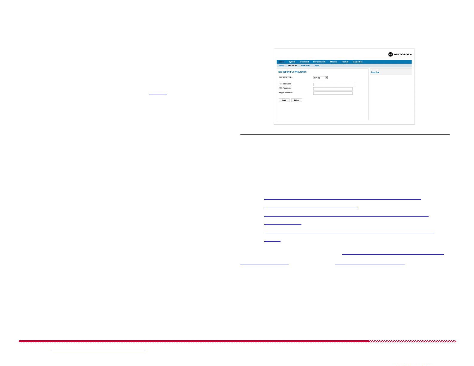
Wired (Ethernet) Network Setup (Continued)
Motorola 2247-N8 DSL Wi-Fi Gateway User Guide
5. Click the Connection Type menu and click the type of ADSL service
that your service provider is providing, then perform the following
steps based on that connection type:
PPPoE or PPPoA: Enter your PPP user name and password, pro-
vided to you by your DSL service provider. Remember, you may
need to call your DSL provider for this information.
DHCP Client: Proceed immediately to step 6.
6. Click the Finish button.
The 2247-N8 shows a progress bar as it waits for the DSL network
connection to initialize. If the DSL network connection cannot initialize, you may be prompted to re-enter your PPP user name and password.
After the waiting period, the browser updates to show the Connec-
tion Information
page. If the broadband status is listed as “Up”, the
connection to the provider DSL network was successful. Seeing the
current network status may require refreshing the browser window.
Close any open browser windows once the broadband connection is
active.
QuickStart Broadband Configuration Page
TIP: If you are having trouble connecting, enter your information again
and make sure the Caps Lock key on your computer is not on. If your service provider network uses another broadband connection method (static
IP assignment or DHCP), or if the automatic detection of DSL settings did
not succeed, you may need to use the advanced configuration options:
“How to configure a Point to Point Protocol (PPPoE or
PPPoA) broadband connection:” on page 47.
“How to configure a DHCP Client assignment broadband
connection:” on page 48.
“How to configure an assigned Static IP broadband connec-
tion:” on page 49.
If you are still having trouble, go to “Frequently Asked Questions - and
Answers (FAQs)” on page 105 or “Basic Troubleshooting” on page 107.
7. Open a new Web browser and enjoy your Internet access through the
Motorola 2247-N8 DSL Wi-Fi Gateway!
Please visit www.motorola.com/us/support for FAQs and additional product documentation. 12
Page 13

Motorola 2247-N8 DSL Wi-Fi Gateway User Guide
Advanced Configuration Procedures
The following procedures cover the advanced configuration of the Motorola 2247-N8 DSL Wi-Fi Gateway using the Web management interface.
How To: Basics
How to connect to your service provider’s network and access the Internet: page 20
How to scan for computers on your local networks page 24
How to add new device aliases to the 2247-N8: page 26
How to delete device alias definitions: page 26
How To: System
How to set or change the 2247-N8 device access code: page 30
How to upgrade your 2247-N8 operating system software: page 31
How to restart the 2247-N8 gateway or DSL connection: page 33
How to enable remote management access to your 2247-N8: page 36
How to end (disable) an existing remote access configuration: page 37
How to restrict the time of day or number of hours computers may access the Internet through the 2247-N8: page 39
How to assign (or remove) Internet access restrictions to specific computers on your network: page 40
How to set the 2247-N8 time zone: page 41
How To: Broadband
How to configure a Point to Point Protocol (PPPoE or PPPoA) broadband connection: page 47
How to configure a DHCP Client assignment broadband connection: page 48
How to configure an assigned Static IP broadband connection: page 49
How to use the Dynamic DNS function of the 2247-N8: page 50
How to configure an IPv6 DHCP Client setting for the 2247-N8 page 53
How to set up AICCU IPv6 tunneling page 53
Please visit www.motorola.com/us/support for FAQs and additional product documentation. 13
Page 14

How to define an IP6in4 deployment tunnel page 54
How to configure 6rd tunneling IPv6 broadband service: page 56
How to set static IPv6 addressing page 57
How To: Home Network
How to configure the 2247-N8 Ethernet port speeds: page 63
How to configure the 2247-N8’s private LAN subnet: page 65
How to enable and configure the DHCP server functionality of the 2247-N8: page 65
How to create a public IP subnet on the 2247-N8 (using public IP addresses): page 66
How to set the 2247-N8 to work with a cascaded router on the home network: page 67
How to access files on a USB storage device page 69
How to upload files to the USB storage device page 69
How to safely disconnect a USB storage device page 69
How To: Wireless
Motorola 2247-N8 DSL Wi-Fi Gateway User Guide
How to use the Wireless Congestion test function: page 72
How to restart the 2247-N8 wireless network: page 72
How to turn the Wi-Fi radio on or off: page 75
How to set the Wi-Fi network name: page 75
How to configure security for your wireless network: page 75
How to use or disable Wi-Fi Protected Setup (WPS): page 78
How to disable Wi-Fi Protected Setup: page 79
How to control and customize the operation of the Wi-Fi radio: page 79
How to restrict wireless access to devices by MAC address: page 80
How to add devices to the MAC filter blacklist or whitelist: page 81
How to delete devices from the MAC filter blacklist or whitelist: page 81
How to run a wireless channel scan: page 82
Please visit www.motorola.com/us/support for FAQs and additional product documentation. 14
Page 15

How To: Firewall
How to change the protection level of the 2247-N8 internal firewall: page 85
How to add a defined service to the hosted application exceptions of the firewall: page 86
How to define a custom service for firewall hosted applications: page 87
How to control packet filter operation: page 91
How to add and create packet filter rules: page 91
How to modify, disable, or delete packet filter rules: page 93
How to assign the 2247-N8’s public IP address to a single LAN client: page 95
How to forward unexpected or unknown incoming traffic to a single default host: page 96
How to modify Denial of Service (DoS) protection settings: page 98
How To: Diagnostics
How to run a general test of the broadband (Internet) connection: page 101
How to attempt to contact a remote server (PING): page 101
How to trace and report the route from the 2247-N8 to a remote server (Traceroute): page 101
Motorola 2247-N8 DSL Wi-Fi Gateway User Guide
How to check DNS configuration by resolving a system name (NSLookup): page 102
How to detect missing or malfunctioning DSL line filters: page 102
How to view, save, and clear system logs: page 104
Please visit www.motorola.com/us/support for FAQs and additional product documentation. 15
Page 16
Motorola 2247-N8 DSL Wi-Fi Gateway User Guide
Advanced Configurations
Most of the time, the basic setup is all you will need to be able to enjoy your Internet connection using the 2247-N8. Use this section if you need to
configure advanced options.
If you need help logging in to the 2247-N8, refer to “Wireless (Wi-Fi) Network Setup” on page 8 or “Wired (Ethernet) Network Setup” on page 10.
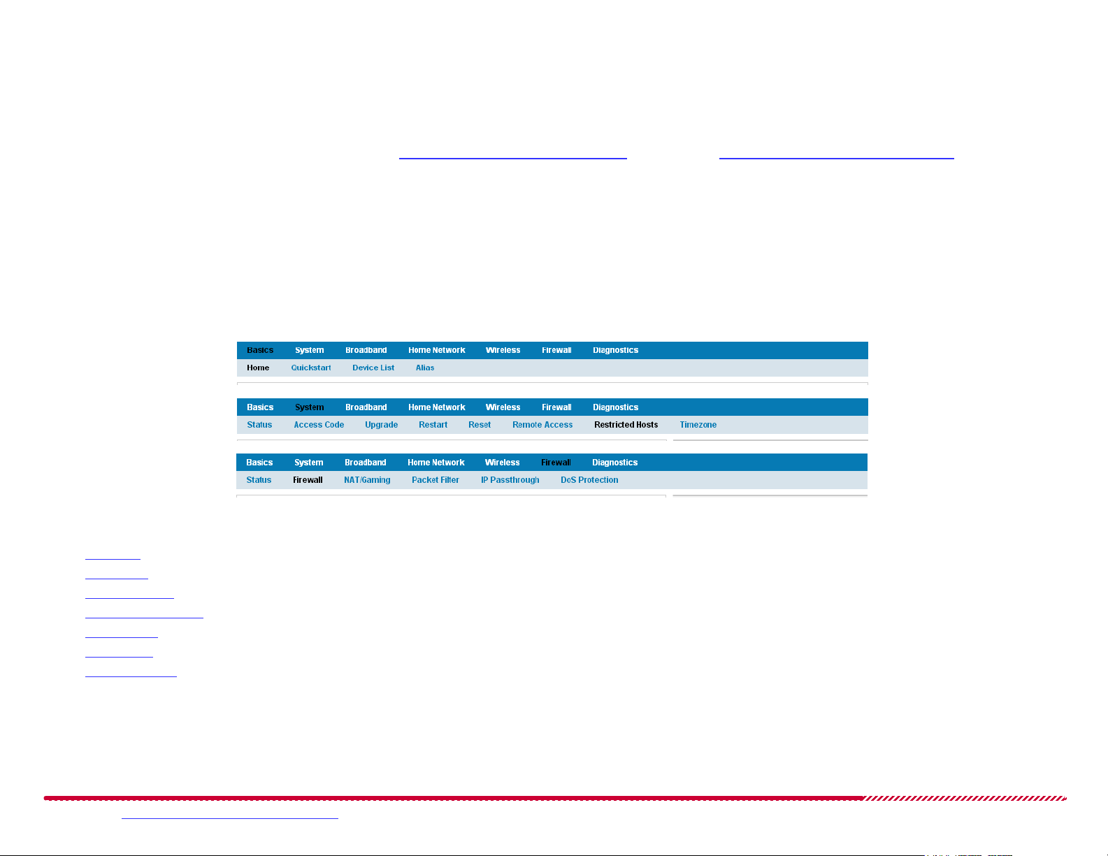
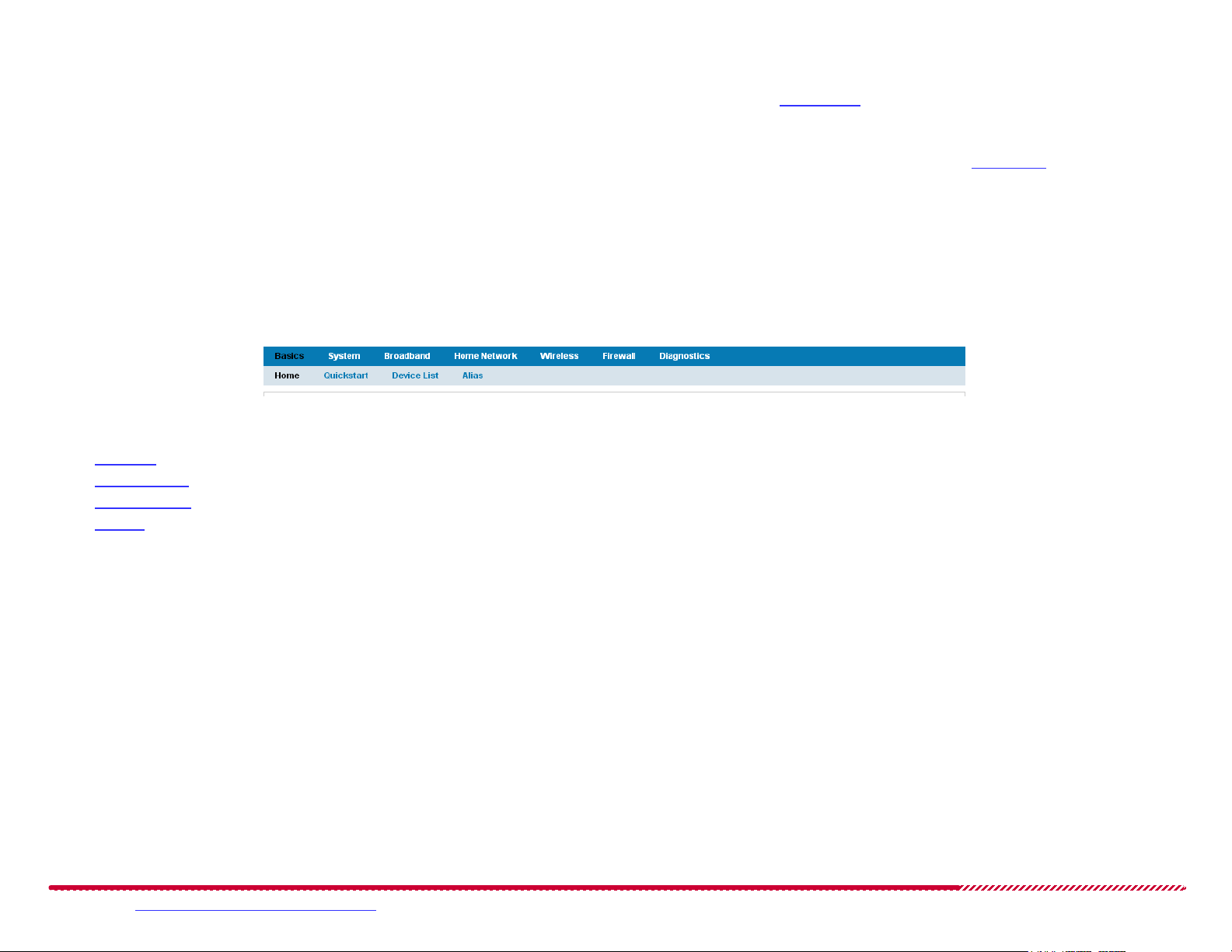
Links Bar
The links located along the top of the Web user interface allow you to monitor, diagnose, and update your 2247-N8. The links bar is divided into top
and bottom sections; the top indicates main categories of 2247-N8 operations, and the bottom shows sub-pages for each top category. As you select
top categories, the lower part of the links bar updates to show the selectable pages in that category.
Links Bar Category Examples (Basics, System, Firewall)
The following sections and subsections describe the links bar categories, with subsections that explain the functions of each sub-page:
“Basics” on page 17.
“System” on page 27.
“Broadband” on page 42.
“Home Network” on page 59.
“Wireless” on page 70
“Firewall” on page 83
“Diagnostics” on page 99
Please visit www.motorola.com/us/support for FAQs and additional product documentation. 16
Page 17
Motorola 2247-N8 DSL Wi-Fi Gateway User Guide
Help
Help displays helpful information about the current 2247-N8 Web page you are visiting. Click the Show Help link at the side of any page if you are
unsure about a configuration option or if you need additional information before making a change to the 2247-N8.
Once the Help link is clicked, the help information for all pages will be shown by default. To hide the help content, click the Hide Help link.
Basics
The Basics category of the links bar includes pages for monitoring the overall condition of the 2247-N8, setting access restrictions, viewing and managing network devices, and other basic functions of the gateway.
Gateway Basics
The Basics category contains the following pages, which will show when Basics is selected in the links bar:
“Home” on page 18
“Quickstart” on page 20
“Device List” on page 23
“Alias” on page 25
Please visit www.motorola.com/us/support for FAQs and additional product documentation. 17
Page 18
Motorola 2247-N8 DSL Wi-Fi Gateway User Guide
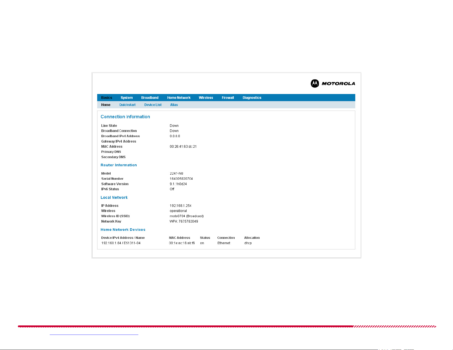
Basics > Home
You may click the Basics > Home links bar item to return to the 2247-N8 home screen. This page provides information and statistics about the DSL
connection, the configuration and identification of the 2247-N8, and the local address configuration.
Basics > Home Page
Please visit www.motorola.com/us/support for FAQs and additional product documentation. 18
Page 19

Motorola 2247-N8 DSL Wi-Fi Gateway User Guide
The Home page shows the following summary information about the 2247-N8 and its local and broadband network connections.
Connection Information, including:
Line State: May be Up (connected) or Down (disconnected).
Broadband Connection: The current state - Up (active) or Down (not active) - of the Digital Subscriber Line (DSL) technology supporting the
connection path to the Internet.
Broadband IPv4 Address: The public IP address of your device, whether dynamically or statically assigned.
Gateway IPv4 Address: Your ISP's gateway router IP address.
MAC Address: Your 2247-N8’s unique hardware address identifier.
Primary DNS: The IP Address of the Primary Domain Name Server.
Secondary DNS: The IP Address of the backup Domain Name Server, if available.
Router Information, including:
Model: The Motorola model number of the gateway.
Serial Number: This is the unique serial number of your 2247-N8.
Software Version: This is the version number of the current embedded software in your 2247-N8 gateway.
IPv6 Status: Shows if the 2247-N8 is configured to support Internet Protocol Version 6 (IPv6) and Version 4 (IPv4) addressing (On), or only
support IPv4 addressing (Off).
Local Network information, including:
IP Address: The IP address of the 2247-N8 on the network.
Wireless: The operational state of the 2247-N8 wireless network. May be enabled (on) or disabled (off).
Wireless ID (SSID): The name assigned to the wireless network.
Network Key: The wireless network security key, if WEP, WPA-PSK, or WPA-Default Key wireless security are enabled.
Home Network Devices information, including:
Device IPv4 Address/Name: The IP address or name of the device.
MAC Address: The hardware MAC address of the device’s connection to the network.
Status: The current operational status (on or off) of the device.
Connection: The type of physical network connection the device is using to access the 2247-N8.
Allocation: How the device’s IP address and network participation is set up (DHCP or Static).
Note: Further device information is available through the “Device List” page.
Please visit www.motorola.com/us/support for FAQs and additional product documentation. 19
Page 20
Motorola 2247-N8 DSL Wi-Fi Gateway User Guide
BASICS > Quickstart
The first time you start up your 2247-N8 and connect to the web management interface, the 2247-N8 automatically displays the Quickstart page. This
page leads you through the very basic steps of controlling access to your Web management interface and attempting a basic connection to your service provider’s network.
Basics > Quickstart Page
How to - connect to your service provider’s network and access the Internet:
1. Install, turn on, and log into the 2247-N8, as described in “Connecting the Gateway” on page 6, and in “Wireless (Wi-Fi) Network Setup” on page 8
or “Wired (Ethernet) Network Setup” on page 10. When you first connect to the Web management interface through your Web browser, the
Quickstart page is automatically shown.
Please visit www.motorola.com/us/support for FAQs and additional product documentation. 20
Page 21
Motorola 2247-N8 DSL Wi-Fi Gateway User Guide
2. Select if you will require a password or access code to use the Web management interface in the future. Read the information on the Quickstart
page and choose your access restriction setting. Click the Allow Unrestricted LAN Access pull-down menu and choose On or Off.
To allow connections to the web management interface without access code (password) authentication, you will turn Unrestricted LAN Access
On.
IMPORTANT: Motorola does not recommend allowing unrestricted LAN access to your 2247-N8. Not securing the Web management interface means
that anyone who has physical access to the 2247-N8 can make changes to your device configuration, and can bypass or eliminate security restrictions,
change passwords, lock you out of the management interface, and disrupt your broadband connection.
To require the use of a password, you will turn it Off, then set your access code, as described in the following steps.
3. Choose the access code that you will use for accessing the Web management interface:
To use the access code that was assigned to the 2247-N8 in the factory, click the Use Default Access Code button.
Note: The default access code is printed on a label affixed to the bottom of the 2247-N8, labeled “Device Access Code”.
To use a new, custom access code:
a. Type the default access code (from the label on the bottom of the 2247-N8) in the Enter Old Access Code input field.
b. Type a new access code (password) in the Enter New Access Code field, then type it again in the Retype New Access Code field. Choose a code
that is easy for you to remember but difficult for someone else to guess.
c. Click the Use New Access Code button.
After you make your choice between restricted and unrestricted LAN access (you can change it later - see “Acc ess C od e” on page 29), the 2247-N8
Web Interface displays a simplified Broadband Configuration page.
Please visit www.motorola.com/us/support for FAQs and additional product documentation. 21
Page 22
Motorola 2247-N8 DSL Wi-Fi Gateway User Guide
Quickstart Broadband Configuration Fields
4. Click the Connection Type pull-down menu and click the type of DSL connection that your service provider supplied to your DSL enabled tele-
phone line:
PPPoE: for Point to Point Protocol over Ethernet broadband service. In the United States, PPPoE is the most common Point to Point Protocol
ADSL service type available.
PPPoA: for Point to Point Protocol over Asynchronous Transfer Mode (ATM) broadband service. If your service provider uses an ATM broad-
band connection to support your ADSL service, choose this selection.
DHCP Client: for an ADSL connection that uses Dynamic Host Configuration Protocol to configure the broadband connection type and settings
for the 2247-N8.
5. Type the user name assigned to you by your service provider in the PPP Username field.
Note: the user name value may be a single word, or it may contain “@” symbols and periods (e.g: “myname@mydslservice.net”).
6. Type the password that your service provider assigned when the ADSL connection was installed or set up in the PPP Password field. To confirm
that the password was entered correctly, type the password again in the Retype Password field.
7. Click the Finish button.
The Motorola 2247-N8 DSL Wi-Fi Gateway will attempt to make a connection to the service provider network. This process may take a few minutes,
and your Web management interface may update automatically to show you the “Home” page during the process.
Note: If the Quickstart page fails to connect to the service provider’s network, contact your service provider and double-check your user name and
password. If you are still having difficulty connecting, you may attempt the more detailed broadband configuration available on the “Configure” page
described on page 46.
Please visit www.motorola.com/us/support for FAQs and additional product documentation. 22
Page 23
Motorola 2247-N8 DSL Wi-Fi Gateway User Guide
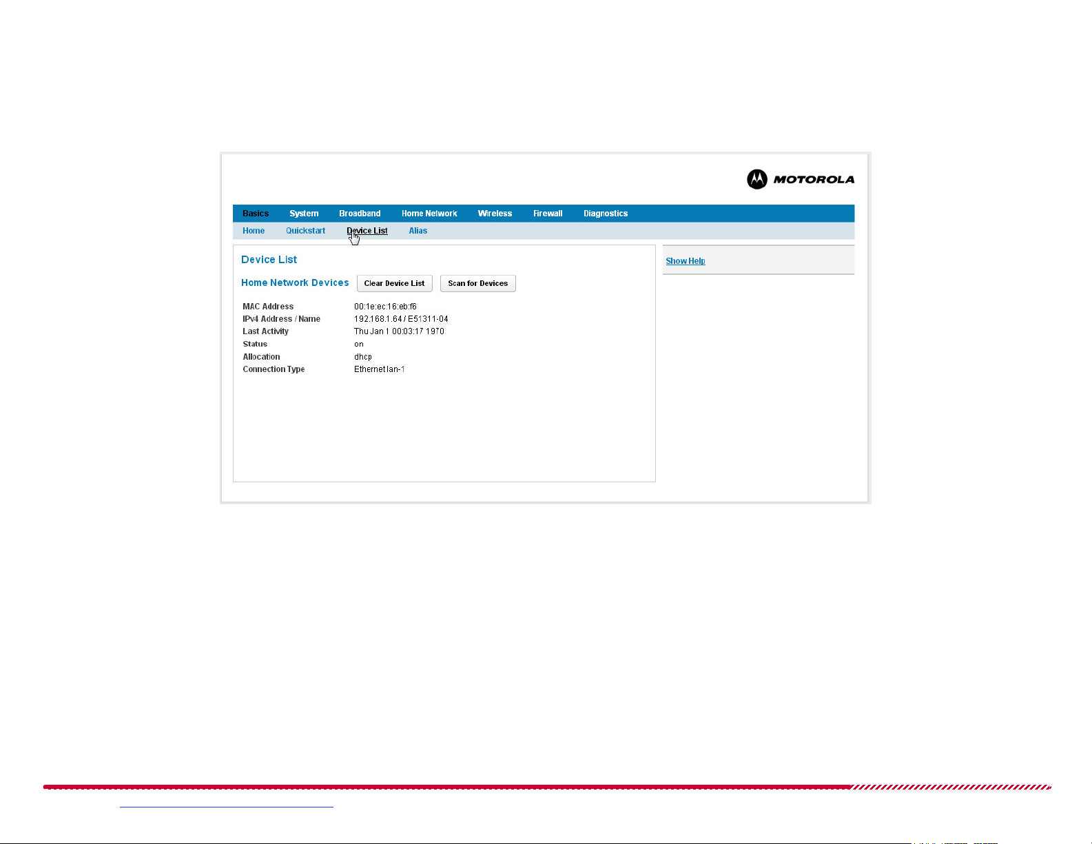
BASICS > Device List
The Device List page shows the devices (computers) that the 2247-N8 has detected on the home network.
Basics > Device List Page
At any time, you may click the Clear Device List button to remove all known devices from the list. This can be useful if you have replaced devices in
your home network, or if guests have used your home network in the past.
Please visit www.motorola.com/us/support for FAQs and additional product documentation. 23
Page 24

Motorola 2247-N8 DSL Wi-Fi Gateway User Guide
The Device List page shows the following information for each known device:
MAC Address: Hardware MAC address of the discovered device.
IPv4 Address / Name: IP Address and any advertised name of the device.
IPv6 Address / Name: IPv6 Address and name of the device, if IPv6 is in use.
Last Activity: The last date and time that the 2247-N8 recorded activity (traffic) from the listed device.
Status: The current operational status of the device.
Allocation: The method used to assign the IPv4 or IPv6 address to the device (static or dhcp).
Connection Type: The network type and (for Ethernet connections) port number used to connect the device to the 2247-N8.
If a device in the list supports Universal Plug and Play (UPnP), the device’s Universally Unique Identifier (UUID) is also shown.
How to - scan for computers on your local networks
Start at the Basics > Device List page.
Click the Scan for Devices button to examine the Ethernet and wireless networks supported by the 2247-N8 and add any detected devices to the
Device List. The 2247-N8 will scan the wired and wireless network for any devices, and add them to the Device List.
Scanning for devices may take a short time (less than 1 minute), and does not interrupt network or Internet service.
Please visit www.motorola.com/us/support for FAQs and additional product documentation. 24
Page 25
Motorola 2247-N8 DSL Wi-Fi Gateway User Guide
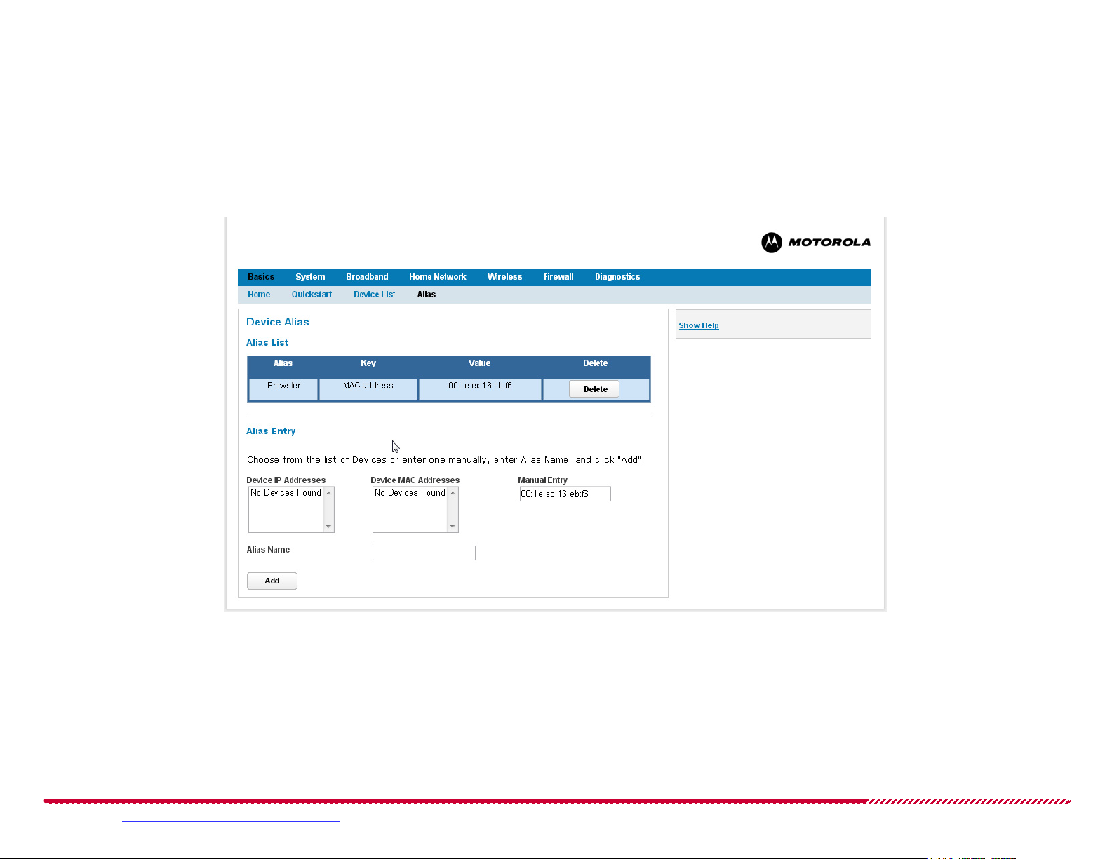
BASICS > Alias
The Alias page allows devices on the 2247-N8 network to be identified by descriptive alias names, instead of IP or MAC addresses. Use it to assign easy
to remember names to devices on your network. The alias names assigned from this page do not change the client configurations, they only appear in
the pages of the 2247-N8 Web management interface. These aliases provide a means to identify devices more easily than a numerical IP or MAC
address. New aliases can be assigned to known devices, or created in advance for devices that you plan to add to the network.
Basics > Alias Page
If any devices have been assigned aliases on your system, the Device Alias page shows them in an Alias List table. The Alias List table shows the following information for each device:
Alias: The custom alias name assigned to the device.
Key: The type of address (MAC or IP) that the alias is associated with.
Value: the IP or MAC address identifying the device.
Please visit www.motorola.com/us/support for FAQs and additional product documentation. 25
Page 26

Motorola 2247-N8 DSL Wi-Fi Gateway User Guide
How to - add new device aliases to the 2247-N8:
Start at the Basics > Alias page.
1. Enter the IP or MAC address of the device:
a. If the device has already connected to the 2247-N8 networks, find and click the device address in the Device IP Addresses or Device MAC
Addresses
lists.
Note: If the device that you are defining an alias for uses DHCP to obtain an IP address, associate the new alias with the device’s MAC address. Associ-
ating the alias with the IP address may cause the device alias to be automatically assigned to a different device as it “follows” the dynamically assigned
IP address.
b. If the device has not connected to the 2247-N8 networks, you may type either an IP or MAC address in the Manual Entry input field.
2. Type an alias in the Alias Name input field.
3. Click the Add button. The new alias is added to the Alias List table.
How to - delete device alias definitions:
You may delete any alias definition by clicking on the associated Delete button in the Alias List table. Deleting the alias does not remove the device
from the network, it only removes the alias name from the device - the 2247-N8 will still record the device’s IP or MAC address in logs and messages.
Please visit www.motorola.com/us/support for FAQs and additional product documentation. 26
Page 27
Motorola 2247-N8 DSL Wi-Fi Gateway User Guide
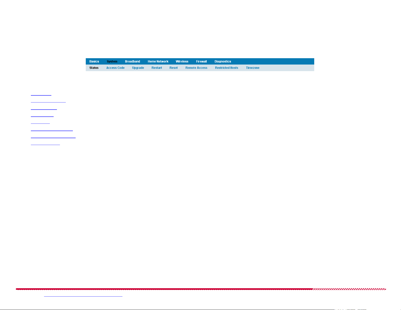
System
The System category of the links bar provides access to overall gateway functions for access, resets, software upgrades, and other system functions.
Gateway System
The System category contains the following pages, which will show when System is selected in the links bar:
“Status” on page 28
“Access Code” on page 29
“Upgrade” on page 31
“Restart” on page 33
“Reset” on page 34
“Remote Access” on page 35
“Restricted Hosts” on page 38
“Timezone” on page 41
Please visit www.motorola.com/us/support for FAQs and additional product documentation. 27
Page 28
Motorola 2247-N8 DSL Wi-Fi Gateway User Guide
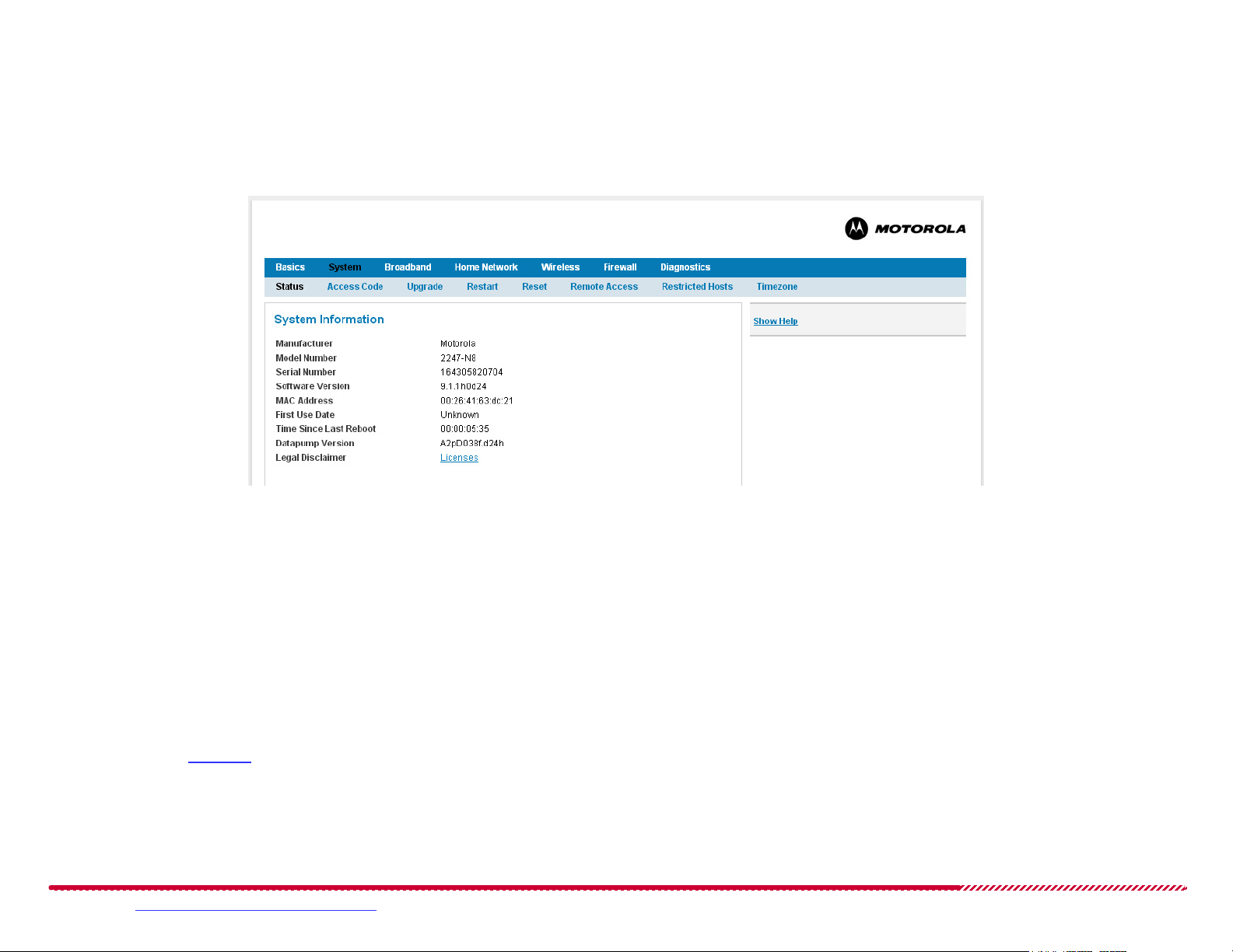
System > Status
The System > Status page shows a summary of the 2247-N8 device’s manufacturing and hardware information, software versions, and system uptime
information.
System > Status Page
The following information is shown on the System > Status page:
Manufacturer: The name of the 2247-N8’s manufacturer.
Model Number: The manufacturing model number of your gateway.
Serial Number: The unique serial number of your gateway.
Software Version: The version number of the current embedded software image in your gateway.
MAC Address: A unique hardware address of this gateway.
First Use Date: Date and time when the 2247-N8 was first used, or the last time the 2247-N8 was started after being reset to factory
defaults.
Time Since Last Reboot: Elapsed time (in days:hours:minutes:seconds) since the last reboot of the 2247-N8.
Datapump Version: Revision number of the underlying DSL datapump operating software.
You may click the Licenses link to open a list of product licensing information for software used on the 2247-N8.
Please visit www.motorola.com/us/support for FAQs and additional product documentation. 28
Page 29
Motorola 2247-N8 DSL Wi-Fi Gateway User Guide
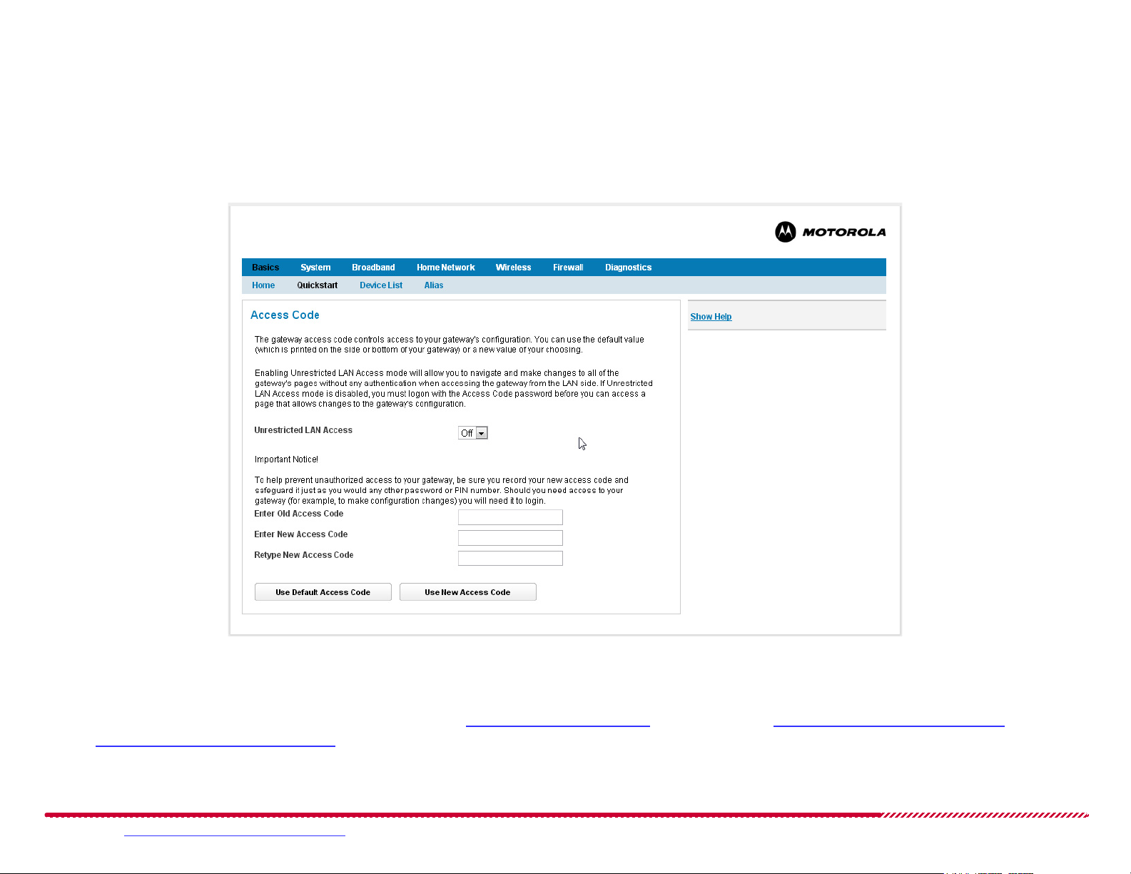
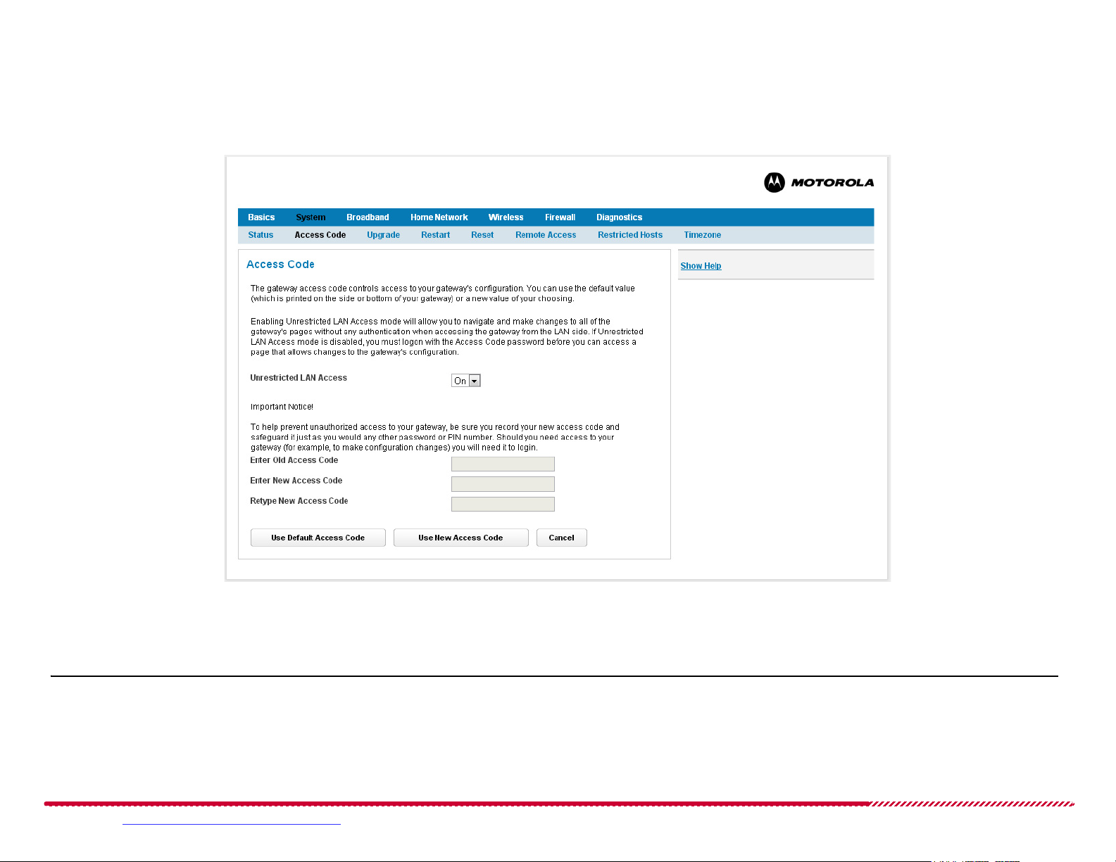
System > Access Code
The Access Code page gives you control over the use of a device access code (password) for access to the Web management interface.
System > Access Code Page
Unrestricted LAN Access - When the pull-down menu is set to On, any device on the local area network can access and make changes to the
2247-N8 configuration without providing a password. When set to Off, the 2247-N8 requires a user name and password before granting
access to the management interfaces.
IMPORTANT: Motorola does not recommend allowing unrestricted LAN access to your 2247-N8. Not securing the Web management interface means
that anyone who has physical access to the 2247-N8 can make changes to your device configuration, and can bypass or eliminate security restrictions,
change passwords, lock you out of the management interface, and disrupt your broadband connection.
Please visit www.motorola.com/us/support for FAQs and additional product documentation. 29
Page 30
Motorola 2247-N8 DSL Wi-Fi Gateway User Guide
Access Codes: When unrestricted LAN access is Off, the 2247-N8 requires an access code. The default access code is the Device Access Code
that is printed on a label attached to the outside (bottom) of the 2247-N8 at the factory.
Note: If you use password protection, your user name is “admin”.
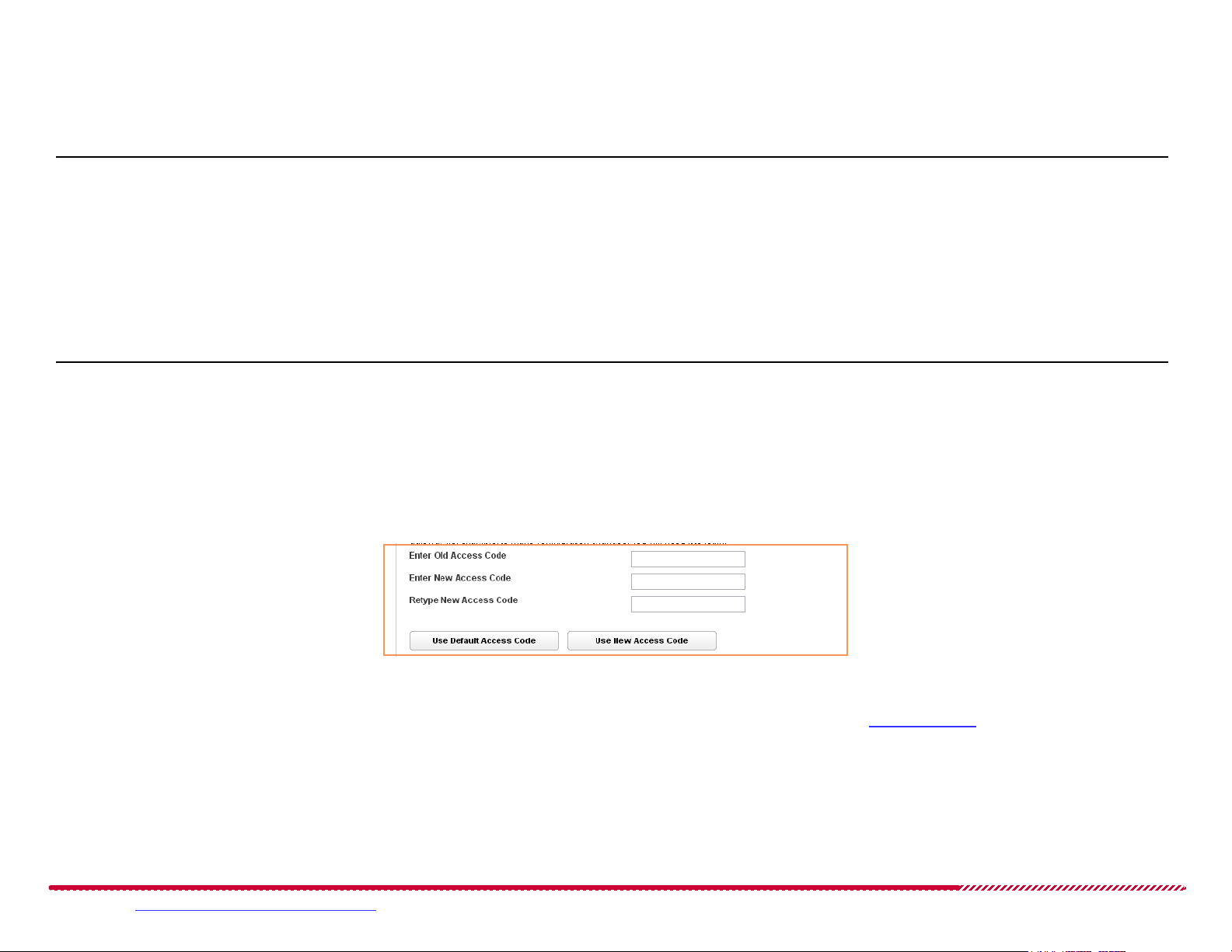
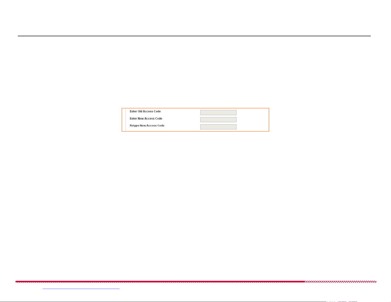
How to - set or change the 2247-N8 device access code:
Start at the System > Access Code page.
Use the Access Code fields as follows;
Type the current or default access code in the Enter Old Access Code input field.
Type a new access code (password) in the Enter New Access Code field, then type it again in the Retype New Access Code field. Choose
a code that is easy for you to remember but difficult for someone else to guess.
Click the Use New Access Code button to save the new setting to the 2247-N8.
If you want to return to the default access code, click the Use Default Access Code button at the bottom of the page.
Please visit www.motorola.com/us/support for FAQs and additional product documentation. 30
Page 31

System > Upgrade
Use the System > Upgrade page to load new operating software on your 2247-N8.
System > Upgrade Page
Motorola 2247-N8 DSL Wi-Fi Gateway User Guide
The Upgrade page shows the Current software version number at the top of the page.
How to - upgrade your 2247-N8 operating system software:
Start at the System > Upgrade page.
NOTE: You will not be able to access the Internet during a software upgrade!
1. Download an updated software image file from your service provider or from Motorola. Store the software file on the computer that you are using
to access the 2247-N8 Web management interface.
Please visit www.motorola.com/us/support for FAQs and additional product documentation. 31
Page 32

Motorola 2247-N8 DSL Wi-Fi Gateway User Guide
IMPORTANT: Verify that the software image that you download is specifically for the Motorola 2247-N8 DSL Wi-Fi Gateway!
2. Click the Choose File or Browse button on the Upgrade page. A file browser window opens. Use the file browser to locate the downloaded software image file on your computer and select it.
After the file is selected, the Upgrade screen shows the file name in place of the “No file chosen” note or empty input field next to the Choose
File/Browse button.
3. Click the Upgrade button to start loading the new software image file to the 2247-N8. The Power light on the front panel of the 2247-N8 will flash
red while the upgrade takes place.
IMPORTANT: Do not disconnect or turn off the power to the 2247-N8 during the software upgrade! If the upgrade is interrupted, the firmware image
on the 2247-N8 may become corrupted and unrecoverable, making the 2247-N8 unable to start or re-attempt an upgrade.
The installation of the new software may take a few minutes. Wait for the upgrade to complete. During this time, the Web management interface
will display a repeating countdown.
4. Wait for the 2247-N8 to restart and load the new software. The Web management interface should re-initialize after the 2247-N8 restarts, and the
“Home” page will show the new software image version number.
Please visit www.motorola.com/us/support for FAQs and additional product documentation. 32
Page 33

Motorola 2247-N8 DSL Wi-Fi Gateway User Guide
System > Restart
The System > Restart page lets you shut down and restart the 2247-N8 gateway and all interfaces, or shut down and restart only the broadband connection.
NOTE: Restarting the gateway or the broadband connection will interrupt your Internet service!
System > Restart Page
How to - restart the 2247-N8 gateway or DSL connection:
Click the Restart Gateway button to restart the 2247-N8. The Web management session will end, and the 2247-N8 will disconnect all wireless and
Ethernet network clients, shut down the broadband connection, and turn off the USB port. Then, the 2247-N8 will start up normally, loading the
most recently saved configuration settings.
Click the Restart Connection button to restart the 2247-N8 broadband connection without interrupting the operation of the Local Area Ethernet or
wireless networks, or interrupting the operation of the 2247-N8 USB port.
Please visit www.motorola.com/us/support for FAQs and additional product documentation. 33
Page 34

Motorola 2247-N8 DSL Wi-Fi Gateway User Guide
System > Reset
The System > Reset page lets you return the 2247-N8 configuration to the factory default settings. This will remove all configuration changes to the
2247-N8, including access code changes, broadband connection configuration, home network configurations, and any other custom settings you have
made.
System > Reset Page
NOTE: Resetting the gateway will interrupt your Internet service. You must re-connect to your service provider’s network as described in the Quick Start
Guide, “Wireless (Wi-Fi) Network Setup” on page 8, or “Wired (Ethernet) Network Setup” on page 10.
Click the Reset Gateway button to restore the 2247-N8 to its factory default configuration.
Please visit www.motorola.com/us/support for FAQs and additional product documentation. 34
Page 35

Motorola 2247-N8 DSL Wi-Fi Gateway User Guide
System > Remote Access
The Remote Access page lets you grant access to your 2247-N8 from the Internet. This function can be used for advanced troubleshooting or remote
configuration.
Note: Enabling remote access allows anyone who knows, or can determine the password, port ID, and URL (address) of your 2247-N8 to view any con-
figuration settings or change the operation of your gateway.
System > Remote Access Page
If Remote access is not currently enabled, the Remote Access page will let you configure and enable it. If remote access has been enabled, the
Remote Access page will indicate that, and provides a button to disable it.
Please visit www.motorola.com/us/support for FAQs and additional product documentation. 35
Page 36

Motorola 2247-N8 DSL Wi-Fi Gateway User Guide
How to - enable remote management access to your 2247-N8:
Open the System > Remote Access page.
1. Type a username and password combination in the Remote Access page. The password must be at least 8 characters long, and must include at
least two of the following types of characters:
alphabetic (letter) characters,
numeric (number) characters,
special characters (! @ # $ % ^ & * , etc)
2. If necessary, type a custom port number for HTTP access to the 2247-N8 remote access session in the Port field.
3. Set the time limits for remote access:
a. Click the User Inactivity Timeout pull-down menu and select a maximum time that the Remote Access session may be left idle before it is dis-
connected.
b. Click the Feature Duration Timeout pull-down menu and choose a time that the Remote Access feature will remain available. Set this number
to as low a value as you and the administrator or technician that will access your 2247-N8 feel is practical.
4. Click one of the Permissions selection buttons to set the type of remote access to allow:
Read/Write - allow the session to make changes to the 2247-N8 configuration.
Read Only - allow the remote access session to view, but not change, the configuration and collected statistics of the 2247-N8.
5. Click the Enable Remote Access button.
The 2247-N8 updates the Remote Access page and displays the current remote access settings, shows the URL that a remote access client must use
to connect to the remote access session, and provides a button for ending the remote access session. The remote access client will need to connect to the URL shown on the Remote Access page, and will need to log in with the username “tech” and the password configured when access
was enabled.
Please visit www.motorola.com/us/support for FAQs and additional product documentation. 36
Page 37

Motorola 2247-N8 DSL Wi-Fi Gateway User Guide
How to - end (disable) an existing remote access configuration:
Open the System > Remote Access page.
If the 2247-N8 is currently configured to support a remote access connection, a notification message is shown at the top of the Remote Access
page. To turn the remote access capability off, click the Disable Remote Access button under the Access URL.
Please visit www.motorola.com/us/support for FAQs and additional product documentation. 37
Page 38

Motorola 2247-N8 DSL Wi-Fi Gateway User Guide
System > Restricted Hosts
The System > Restricted Hosts page lets you control access to the Internet through the 2247-N8. This restriction can be used to set “windows” of
time during which certain computers on your network are allowed access to the Internet. Additionally, an access “budget” of time may be defined for
devices on the network, defining the maximum number of hours that the device may access the Internet on that date. Host restriction also allows for
the creation of accounts that provide access only to the 2247-N8’s Internet connection, or that deny network and Internet access entirely.
System > Restricted Hosts Page
Host restriction is accomplished by creating Access Profiles, each of which may have custom configurations for the days of the week. Those profiles are
then applied to known devices.
Note: Restricted Host profiles require the configuration of the 2247-N8s time zone, as described in “Timezone” on page 41.
Please visit www.motorola.com/us/support for FAQs and additional product documentation. 38
Page 39

Motorola 2247-N8 DSL Wi-Fi Gateway User Guide
How to - restrict the time of day or number of hours computers may access the Internet through the 2247-N8:
Open the System > Restricted Hosts page.
Host restriction requires the creation of at least one Access Profile to define a set of rules. Once one or more profiles are created, they may be
applied to devices on your network as described in “How to assign (or remove) Internet access restrictions to specific computers on your net-
work:” on page 40.
1. Click the Add New Profile button. A new profile is created in the Access Profile table of the Restricted Hosts page.
2. Click the Edit button associated with the new profile. The calendar view of the profile, showing the days of the week and default configuration values, is shown below the Access Profiles table.
3. Click the Start Time and End Time pull-down menus for each day of the week in the new profile.
To define an Internet access “window”: Set the Start Time field for the beginning of the available time frame, and set the End Time field for
the time of day when Internet access will expire. The time values are specified in AM/PM time, where “12:00 AM” is midnight.
To block Internet access for the entire day: Click the Start Time pull-down menu and select “Blocked”. The profile will deny Internet access to
any devices that you assign the profile to for that day of the week.
4. Set an optional usage budget for each day. Click the Max Usage Hours pull-down menu for each day of the week and choose a total number of
hours (from 0.5 to 24 - with 24 indicating no limitation) that the profile will allow a client to access the Internet on that day.
5. Click the Save button to assign the restrictions and maximum usage values to the access profile.
Please visit www.motorola.com/us/support for FAQs and additional product documentation. 39
Page 40

Motorola 2247-N8 DSL Wi-Fi Gateway User Guide
How to - assign (or remove) Internet access restrictions to specific computers on your network:
You may assign a pre-defined Wi-Fi user restriction profile (the GuestNetwork or Blacklist default profiles) or a custom profile (created in “How to
restrict the time of day or number of hours computers may access the Internet through the 2247-N8:” on page 39) to devices on your network.
Open the System > Restricted Hosts page.
Note: this procedure requires that the computers to restrict are “known” to the 2247-N8. Simply connecting to the 2247-N8 wired or wireless network
will let the 2247-N8 discover the device. You may also refresh the list as described in “How to scan for computers on your local networks” on page 24.
It may be easier to identify specific devices in the table if you first assign an alias to them, as described in “How to add new device aliases to the
2247-N8:” on page 26.
1. Locate the computer that you want to restrict in the Device Restriction table at the bottom of the page. This table lists all client devices that the
2247-N8 has learned the MAC (hardware) address of.
2. Click the Restriction Type pull-down menu associated with the device. Select a restriction type to apply to the device:
None: give the device unrestricted access to the Internet.
GuestNetwork (for Wi-Fi users only): restrict the wireless device from accessing any computers on your home (wired or Wi-Fi) network.
Blacklist (for Wi-Fi users only): restrict the wireless device from accessing the Internet, or any computers on the home networks.
ProfileX: Select a profile (where “X” is the profile number) listed in the pull-down menu to enforce the chosen access profile on that device.
3. Repeat the selection process for any devices that you want to apply an access restriction to. You may assign the same access profile to any number
of devices known to the 2247-N8.
4. Click the Save button to assign the access profile(s) to the devices.
Please visit www.motorola.com/us/support for FAQs and additional product documentation. 40
Page 41

Motorola 2247-N8 DSL Wi-Fi Gateway User Guide
System > Timezone
The 2247-N8 Timezone page lets you specify the time zone that the 2247-N8 resides in. The time zone setting affects the 2247-N8 system clock.
Note: Correct time zone configuration is essential for the operation of the “Restricted Hosts” function of the 2247-N8.
System > Timezone Page
How to - set the 2247-N8 time zone:
Locate and click on your time zone in the Time Zone list, then click the Save button.
Please visit www.motorola.com/us/support for FAQs and additional product documentation. 41
Page 42

Motorola 2247-N8 DSL Wi-Fi Gateway User Guide
Broadband
The Broadband category of the 2247-N8 links bar provides access to setup and monitoring information for the 2247-N8 DSL connection.
Gateway Broadband
The Broadband category contains the following pages, which will show when Broadband is selected in the links bar:
“Status” on page 43
“Configure” on page 46
“Dynamic DNS” on page 50
“IPv6” on page 52
Please visit www.motorola.com/us/support for FAQs and additional product documentation. 42
Page 43

Motorola 2247-N8 DSL Wi-Fi Gateway User Guide
Broadband > Status
The Broadband > Status page shows information about the configuration and condition of the 2247-N8 connection to the service provider DSL network.
Broadband > Status page
At any time, you may reset the statistics and error counters by clicking the Clear Statistics button.
Please visit www.motorola.com/us/support for FAQs and additional product documentation. 43
Page 44

Motorola 2247-N8 DSL Wi-Fi Gateway User Guide
The following information is shown on the Broadband > Status page:
General device status information, including:
Broadband Connection: The condition of the 2247-N8 connection to the Internet. May be Up (connected) or Down (disconnected).
Broadband IPv4 Address: The public IP address of your 2247-N8, whether dynamically or statically assigned.
Gateway IPv4 Address: Your ISP's gateway router IP address.
MAC Address: Your 2247-N8’s unique hardware address identifier.
Primary DNS: The name or IP Address of the Primary Domain Name Server.
Secondary DNS: The name or IP Address of the backup Domain Name Server, if available.
MTU: Maximum Transmittable Unit size before packets are broken into multiple packets.
DSL Status, including:
Line State: May be Up (connected) or Down (disconnected).
Downstream Sync Rate: This is the rate at which your connection can download (receive) data on your DSL line, in kilobits per second.
Upstream Sync Rate: This is the rate at which your connection can upload (send) data on your DSL line, in kilobits per second.
Modulation: Method of regulating the DSL signal. DMT (Discrete MultiTone) allows connections to work better when certain radio transmit-
ters are present.
Data Path: Type of path used by the device's processor.
Downstream and Upstream statistics for the DSL connection, including:
SN Margin (dB): Signal to noise margin, in decibels. Reflects the amount of unwanted “noise” on the DSL line.
Line Attenuation (dB): Amount of reduction in signal strength on the DSL line, in decibels.
Output Power (dBm): Measure of power output in decibels (dB) referenced to one milliwatt (mW).
Errored Seconds: The number of uncorrected seconds after being down for seven consecutive seconds.
Loss of Signal: Error events caused by the absence of any signal for any reason, such as a disconnected cable or loss of power.
Loss of Frame: Error events where a signal is detected but cannot sync with signal caused by mismatched protocols, wrong ISP connection
configuration, or faulty cable.
FEC Errors: (Forwarded Error Correction errors) Count of received errored packets that were fixed successfully without a retry.
CRC Errors: Number of times data packets have had to be resent due to errors in transmission or reception.
IPv6 Status, including:
Status: May be Enabled or Unavailable.
Global Unicast IPv6 Address: The public IPv6 address of your device, whether dynamically or statically assigned.
Border Relay IPv4 Address: The public IPv4 address of your device.
Please visit www.motorola.com/us/support for FAQs and additional product documentation. 44
Page 45

IPv4 Statistics:
Transmit Packets: IPv4 packets transmitted.
Transmit Errors: Errors on IPv4 packets transmitted.
Transmit Discards: IPv4 packets dropped.
IPv6 Statistics:
Transmit Packets: IPv6 packets transmitted.
Transmit Errors: Errors on IPv6 packets transmitted.
Transmit Discards: IPv6 packets dropped.
Motorola 2247-N8 DSL Wi-Fi Gateway User Guide
Please visit www.motorola.com/us/support for FAQs and additional product documentation. 45
Page 46

Motorola 2247-N8 DSL Wi-Fi Gateway User Guide
Broadband > Configure
The Broadband > Configure page provides the functions needed to set up your 2247-N8 broadband DSL connection.
Broadband > Configure Page
The procedure that you must perform to customize the broadband configuration of the 2247-N8 depends on the connection type that you are modifying: PPPoE, PPPoA, Static IP, or DHCP Client.
Please visit www.motorola.com/us/support for FAQs and additional product documentation. 46
Page 47

Motorola 2247-N8 DSL Wi-Fi Gateway User Guide
How to - configure a Point to Point Protocol (PPPoE or PPPoA) broadband connection:
Open the Broadband > Configure page.
The two supported Point to Point Protocol variants (PPP over Ethernet and PPP over ATM) are configured identically. Your service provider will be
able to tell you which protocol to select and what your username, password, VPI and VCI values are.
1. Click the Connection Type pull-down menu and choose the protocol supported by your service provider: PPPoE or PPPoA.
2. Type your service provider account credentials in the PPP Username and PPP Password fields. Retype your password exactly in the Retype
Password
3. Click the PPP Connection Type pull-down menu and choose the way the 2247-N8 will connect to the broadband PPP network:
Always Attempt to Connect: The 2247-N8 will attempt to keep the broadband connection active at all times.
Connect Manually: The 2247-N8 will only connect when you manually enter broadband connection credentials from the Broadband > Con-
figuration
Connect on Demand: The 2247-N8 will use stored PPP credentials to log in when a connected client device attempts to connect to a service
or device on the Internet, and will close the connection down after a period of activity.
field for confirmation.
or Quickstart pages.
4. Set the Domain Name Service (DNS), Network Address Translation (NAT) and bridging configuration of your 2247-N8:
If you want to use a DNS server not set by your service provider, set the Use Received DNS Addresses pull-down menu to Off. Type the
IP address of a DNS server in the Primary DNS Address field. If desired, type an alternate DNS server’s IP address in the Secondary DNS
Address
If you are using NAT (with a number of devices on a private wired or wireless network), set the NAT Enable pull-down menu to On.
If your ISP requires a routing device on the LAN side of your DSL gateway, turn Bridging On, otherwise, leave it Off.
field.
5. Set Virtual Path and Channel Identifiers, either by automatically detecting them, or specifying values supplied by your service provider:
To have the 2247-N8 attempt to automatically detect and set the channel identifiers, click the Automatic VPI/VCI Detection pull-down
menu and select On (the default).
Please visit www.motorola.com/us/support for FAQs and additional product documentation. 47
Page 48

Motorola 2247-N8 DSL Wi-Fi Gateway User Guide
To manually enter VPI/VCI information from your service provider, click the Automatic VPI/VCI Detection pull-down menu and select Off,
then type the VPI and VCI values in the VPI and VCI input fields.
The most common VPI/VCI combinations are VPI:0 / VCI:35 and VPI:8 / VCI:35. Motorola recommends always using automatic VPI/VCI detection
first, and only manually setting VPI/VCI combinations if your service provider requires another circuit pair and provides the values.
6. Click the Save button to assign the new broadband configuration to the 2247-N8. The broadband interface resets and the 2247-N8 will go through
broadband negotiation.
How to - configure a DHCP Client assignment broadband connection:
Open the Broadband > Configure page.
If your service provider uses Dynamic Host Configuration Protocol (DHCP) to assign a configuration to the 2247-N8, use the following procedure to
set up your broadband connection.
1. Click the Connection Type pull-down menu and choose DHCP Client.
2. Set the Domain Name Service (DNS), Network Address Translation (NAT) and bridging configuration of your 2247-N8:
If you want to use a DNS server not set by your service provider, set the Use Received DNS Addresses pull-down menu to Off. Type the IP
address of a DNS server in the Primary DNS Address field. If desired, type an alternate DNS server’s IP address in the Secondary DNS
Address
If you are using NAT (with a number of devices on a private wired or wireless network), set the NAT Enable pull-down menu to On.
If your ISP requires a routing device on the LAN side of your DSL gateway, turn Bridging On, otherwise, leave it off.
field.
3. Click the Save button to assign the new broadband configuration to the 2247-N8. The broadband interface resets and the 2247-N8 will go through
broadband negotiation.
Please visit www.motorola.com/us/support for FAQs and additional product documentation. 48
Page 49

Motorola 2247-N8 DSL Wi-Fi Gateway User Guide
How to - configure an assigned Static IP broadband connection:
Open the Broadband > Configure page.
1. Click the Connection Type pull-down menu and choose Static IP.
2. Type the IP address of the service provider interface in the IP Address field. Type the network mask value that defines the network portion of the
provider IP address in the Netmask field.
3. Type the IP address of your service provider’s gateway in the Default Gateway input field.
4. Type the IP address of a DNS server in the Primary DNS Address field. If desired, type an alternate DNS server’s IP address in the Secondary
DNS Address
field.
5. Set the Network Address Translation (NAT) and bridging configuration of your 2247-N8:
If you are using NAT (with a number of devices on a private wired or wireless network), click the NAT Enable pull-down menu and set it to On.
If your ISP requires a routing device on the LAN side of your DSL gateway, click the Bridging pull-down menu and select On, otherwise, leave
it off.
6. Click the Save button to assign the new broadband configuration to the 2247-N8. The broadband interface resets and the 2247-N8 will go through
broadband negotiation.
Please visit www.motorola.com/us/support for FAQs and additional product documentation. 49
Page 50

Motorola 2247-N8 DSL Wi-Fi Gateway User Guide
Broadband > Dynamic DNS
The Dynamic DNS page lets you use the Dynamic DNS services supplied by DynDNS (www.dyn.com) to dynamically assign and relay Domain Name Service (DNS) information. The Dynamic DNS service can let you access the devices on your 2247-N8 gateway by domain name, which can make access to
servers or devices on your network easier.
Broadband > Dynamic DNS Page
How to - use the Dynamic DNS function of the 2247-N8:
Open the Broadband > Dynamic DNS page.
Note: Use of Dynamic DNS requires a qualified service account with a dynamic DNS service supplier.
1. Click the Enable DynDNS pull-down menu and turn Dynamic DNS On (enabled) or Off (disabled). If Dynamic DNS is On, continue with the procedure, otherwise, click the Save button to turn Dynamic DNS off.
Please visit www.motorola.com/us/support for FAQs and additional product documentation. 50
Page 51

2. Click the Provider pull-down menu and select a dynamic DNS provider URL from the list.
3. Type a DNS host name associated with your service account in the HostName field.
4. Type your dynamic DNS account credentials in the Username and Password fields.
5. Click the Save button to add the Dynamic DNS configuration to the 2247-N8.
Motorola 2247-N8 DSL Wi-Fi Gateway User Guide
Please visit www.motorola.com/us/support for FAQs and additional product documentation. 51
Page 52

Motorola 2247-N8 DSL Wi-Fi Gateway User Guide
Broadband > IPv6
If your service provider supplies IPv6 service to your 2247-N8, the operation of the IPv6 interface is configured with the Broadband > IPv6 page.
Broadband > IPv6 Page
The 2247-N8 supports several types of IPv6 native or IPv6 rapid deployment types. The configuration parameters and procedures for each type is different, and these procedures are covered in the following section.
Please visit www.motorola.com/us/support for FAQs and additional product documentation. 52
Page 53

Motorola 2247-N8 DSL Wi-Fi Gateway User Guide
How to - configure an IPv6 DHCP Client setting for the 2247-N8
Open the Broadband > IPv6 page.
1. Click the IPv6 Enable pull-down menu and select On to enable IPv6 service, or Off to disable it (the default).
2. Click the WAN IPv6 Connection Type pull-down menu and select IPv6 DHCP Client.
The fields of the IPv6 page update to show DHCP related configuration settings.
3. If your home (local) network will also use IPv6 addressing, click the IPv6 Enable on LAN pull-down menu and click On. Use the fields below the
IPv6 Enable on LAN menu to set the connection type for your local network:
4. Click the LAN IPv6 Connection Type pull-down menu and select the addressing method defined by your IPv6 6rd connection:
a. If the local network will derive local IPv6 addresses from the broadband IPv6 DHCP server, select Delegated Prefix (the default).
b. If your IPv6 network uses static (assigned) addresses, select Static IP. Type the IPv6 address of your 2247-N8 LAN gateway interface in the LAN
IPv6 Address
field.
5. Click the Save button to add the IPv6 Broadband configuration settings. .
How to - set up AICCU IPv6 tunneling
Open the Broadband > IPv6 page.
1. Click the IPv6 Enable pull-down menu and select On to enable IPv6 service, or Off to disable it (the default).
2. Click the WAN IPv6 Connection Type pull-down menu and select AICCU Tunnel.
Please visit www.motorola.com/us/support for FAQs and additional product documentation. 53
Page 54

Motorola 2247-N8 DSL Wi-Fi Gateway User Guide
The fields of the IPv6 page update to show AICCU related configuration settings.
3. Type the username and password of your AICCU tunneling account in the Username and Password fields.
The AICCU username and password will be provided by your service provider as part of your IPv6 tunnel service.
4. If your home (local) network will also use IPv6 addressing, click the IPv6 Enable on LAN pull-down menu and click On. Use the fields below the
IPv6 Enable on LAN menu to set the connection type for your local network:
5. Click the LAN IPv6 Connection Type pull-down menu and select the addressing method defined by your IPv6 6rd connection:
a. If the local network will derive local IPv6 addresses from the broadband IPv6 DHCP server, select Delegated Prefix (the default).
b. If your IPv6 network uses static (assigned) addresses, select Static IP. Type the IPv6 address of your 2247-N8 LAN gateway interface in the LAN
IPv6 Address
field.
Click the Save button to add the IPv6 Broadband configuration settings. .
How to - define an IP6in4 deployment tunnel
Open the Broadband > IPv6 page.
1. Click the IPv6 Enable pull-down menu and select On to enable IPv6 service, or Off to disable it (the default).
2. Click the WAN IPv6 Connection Type pull-down menu and select IP6in4 Tunnel.
Please visit www.motorola.com/us/support for FAQs and additional product documentation. 54
Page 55

Motorola 2247-N8 DSL Wi-Fi Gateway User Guide
The fields of the IPv6 page update to show IP6in4 tunnel configuration settings.
3. Type your Point of Presence address for IPv6 tunneling in the POP IPv4 Address field.
4. Type the 2247-N8 local interface’s IPv6 address in the Local IPv6 Address field.
5. Set the IPv6 address prefix details:
a. Type your service provider’s IPV6 6rd prefix (this value will be unique to your service provider) in the 6rd Prefix input field.
b. Type the length of the 6rd prefix (available from your service provider) in the 6rd Prefix Length field.
6. If your home (local) network will also use IPv6 addressing, click the IPv6 Enable on LAN pull-down menu and click On. Use the fields below the
IPv6 Enable on LAN menu to set the connection type for your local network:
7. Click the LAN IPv6 Connection Type pull-down menu and select the addressing method defined by your IPv6 6rd connection:
a. If the local network will derive local IPv6 addresses from the broadband IPv6 DHCP server, select Delegated Prefix (the default).
b. If your IPv6 network uses static (assigned) addresses, select Static IP. Type the IPv6 address of your 2247-N8 LAN gateway interface in the LAN
IPv6 Address
field.
Click the Save button to add the IPv6 Broadband configuration settings. .
Please visit www.motorola.com/us/support for FAQs and additional product documentation. 55
Page 56

Motorola 2247-N8 DSL Wi-Fi Gateway User Guide
How to - configure 6rd tunneling IPv6 broadband service:
Open the Broadband > IPv6 page.
1. Click the IPv6 Enable pull-down menu and select On to enable IPv6 service, or Off to disable it (the default).
2. Click the WAN IPv6 Connection Type pull-down menu and select 6rd Tunnel.
The fields of the IPv6 page update to show 6rd tunnel configuration settings.
3. Click the IPv6 6rd use dhcp values pull-down menu and select the 6rd DHCP setting of your provider connection:
On (the default) if your provider configures the 6rd tunneling address prefix information and relay address automatically.
Off if you must manually specify the address prefix information and relay address. If the IPv6 6rd use dhcp values pull-down menu is set to
Off, you must configure the following IPv6 6rd values:
a. Type your service provider’s IPV6 6rd prefix (this value will be unique to your service provider) in the 6rd Prefix input field.
b. Type the length of the 6rd prefix (available from your service provider) in the 6rd Prefix Length field.
c. If your provider’s 6rd implementation uses common bits to reduce the number of IPv4 address bits in the IPv6 prefix, enter the number of com-
mon bits in the 6rd IPv4 Common Bits field.
d. Type the Fully-Qualified Domain Name or the IPv4 IP address of your service provider’s 6rd relay gateway (e.g; “6rd.motorola.com” or
“10.10.220.101”) in the 6rd IPv4 Relay Address input field.
Please visit www.motorola.com/us/support for FAQs and additional product documentation. 56
Page 57

Motorola 2247-N8 DSL Wi-Fi Gateway User Guide
4. If your home (local) network will also use IPv6 addressing, click the IPv6 Enable on LAN pull-down menu and click On. Use the fields below the
IPv6 Enable on LAN menu to set the connection type for your local network:
5. Click the LAN IPv6 Connection Type pull-down menu and select the addressing method defined by your IPv6 6rd connection:
a. If the local network will derive local IPv6 addresses from the broadband IPv6 tunnel, select Delegated Prefix (the default) and proceed to step 6.
b. If your IPv6 network uses static (assigned) addresses, select Static IP. Type the IPv6 address of your 2247-N8 LAN gateway interface in the LAN
IPv6 Address
field.
6. Click the Save button to add the IPv6 Broadband configuration settings. .
How to - set static IPv6 addressing
Open the Broadband > IPv6 page.
1. Click the IPv6 Enable pull-down menu and select On to enable IPv6 service, or Off to disable it (the default).
2. Click the WAN IPv6 Connection Type pull-down menu and select Static IP.
The fields of the IPv6 page update to show the static IPv6 assignment settings.
3. Type the 2247-N8 broadband interface’s IPv6 address in the WAN IPv6 Address field.
4. Type the IP address of your service provider’s gateway in the Default Gateway input field.
Please visit www.motorola.com/us/support for FAQs and additional product documentation. 57
Page 58

Motorola 2247-N8 DSL Wi-Fi Gateway User Guide
5. Set the Domain Name Service (DNS) configuration of your 2247-N8. Type the IPv6 address of your service provider’s DNS server in the Primary
DNS Address
field. If desired, type an alternate DNS server’s IP address in the Secondary DNS Address field.
6. If your home (local) network will also use IPv6 addressing, click the IPv6 Enable on LAN pull-down menu and click On. Use the fields below the
IPv6 Enable on LAN menu to set the connection type for your local network:
7. Click the LAN IPv6 Connection Type pull-down menu and select the addressing method defined by your IPv6 6rd connection:
a. If the local network will derive local IPv6 addresses from the broadband IPv6 tunnel, select Delegated Prefix (the default) and proceed to step 6.
b. If your IPv6 network uses static (assigned) addresses, select Static IP. Type the IPv6 address of your 2247-N8 LAN gateway interface in the LAN
IPv6 Address
field.
8. Click the Save button to add the IPv6 Broadband configuration settings. .
Please visit www.motorola.com/us/support for FAQs and additional product documentation. 58
Page 59

Motorola 2247-N8 DSL Wi-Fi Gateway User Guide
Home Network
The Home Network category of the 2247-N8 Web management interface provides access to sub-pages that provide information or control the configuration of the 2247-N8’s local (wired) network connections.
Gateway Home Network
The Home Network category contains the following pages, which will show when Home Network is selected in the links bar:
“Status” on page 60
“Configure” on page 63
“Subnets & DHCP” on page 64
“USB File System” on page 68
Please visit www.motorola.com/us/support for FAQs and additional product documentation. 59
Page 60

Motorola 2247-N8 DSL Wi-Fi Gateway User Guide
Home Network > Status
The Home Network > Status page shows information about the configuration and operation of the 2247-N8 local network ports.
Home Network > Status Page
Please visit www.motorola.com/us/support for FAQs and additional product documentation. 60
Page 61

Motorola 2247-N8 DSL Wi-Fi Gateway User Guide
The following information is shown on the Home Network > Status page:
At any time, you may reset or clear all collected statistics by clicking on the Clear Statistics button at the bottom of the page.
Home Network Status information, including:
Device IPv4 Address: The 2247-N8’s own IP address on the network.
DHCP Netmask: The 2247-N8’s own netmask on the network.
DHCPv4 Start Address: The starting IP address of the DHCP range served by the 2247-N8.
DHCPv4 End Address: The ending IP address of the DHCP range served by the 2247-N8.
DHCP Leases Available: The number of IP addresses of the DHCP range available to be served by the 2247-N8.
DHCP Leases Allocated: The number of IP addresses of the DHCP range currently being served by the 2247-N8.
DHCP Primary Pool: Source pool of the IP addresses served by the 2247-N8, Public or Private.
An Interfaces summary, containing the following information for the home network interfaces (Ethernet and Wireless) of the 2247-N8:
Status: The management setting of the network; enabled or disabled.
Active Devices: The number of currently active devices connected to the network.
Inactive Devices: The number of known devices that have connected to the network previously, but are not currently active or connected to
the network.
A section of IPv6 information, including:
Status: May be Enabled or Unavailable.
Global IPv6 Address: The public IPv6 address of your device, whether dynamically or statically assigned.
Link-local IPv6 Address: The private IPv6 address of your device, whether dynamically or statically assigned.
Router Advertisement Prefix: The IPv6 prefix to include in router advertisements.
IPv6 Delegated LAN Prefix: The IPv6 network address prefix that identifies the gateway network.
IPv4 Statistics, including:
Transmit Packets: IPv4 packets transmitted.
Transmit Errors: Errors on IPv4 packets transmitted.
Transmit Discards: IPv4 packets dropped.
Receive Packets: IPv4 packets received.
Receive Errors: Errors on IPv4 packets received.
Receive Discards: received IPv4 packets dropped.
Please visit www.motorola.com/us/support for FAQs and additional product documentation. 61
Page 62

IPv6 Statistics, including:
Transmit Packets: IPv6 packets transmitted.
Transmit Errors: Errors on IPv6 packets transmitted.
Transmit Discards: IPv6 packets dropped.
LAN Ethernet Statistics:
State: up or down
Transmit Speed: This is the maximum speed of which the port is capable.
Transmit Packets: This is the number of packets sent out from the port.
Transmit Bytes: This is the number of bytes sent out from the port.
Transmit Dropped: This is the number of packets sent out from the port that were dropped.
Transmit Errors: This is the number of errors on packets sent out from the port.
Receive Packets: This is the number of packets received on the port.
Receive Bytes: This is the number of bytes received on the port.
Receive Unicast: This is the number of unicast packets received on the port.
Receive Multicast: This is the number of multicast packets received on the port.
Receive Dropped: This is the number of packets received on the port that were dropped.
Receive Errors: This is the number of errors on packets received on the port.
Motorola 2247-N8 DSL Wi-Fi Gateway User Guide
Please visit www.motorola.com/us/support for FAQs and additional product documentation. 62
Page 63

Motorola 2247-N8 DSL Wi-Fi Gateway User Guide
Home Network > Configure
The Home Network > Configure page lets you set the physical speed and crossover settings of the 2247-N8 Ethernet ports.
Home Network > Configure Page
How to - configure the 2247-N8 Ethernet port speeds:
For each of the Ethernet ports of the 2247-N8, you can set the speed and crossover detection manually.
Note: Motorola strongly recommends leaving the Ethernet port speed and crossover settings at their default values. Only modify these settings if your
network supports older Ethernet devices that are experiencing problems with the autonegotiation settings.
Use the Ethernet pull-down menus to select the speed of the port:
Auto (default automatic negotiation with the connected device) - this setting is the system default, and is recommended for all ports.
10M Full, 10M Half (10 Megabit per second full-duplex or half-duplex)
100M Full, 100M Half (100 Megabit per second full-duplex or half-duplex)
Click the MDI-X pull-down menus to set the automatic crossover detection setting of each port: Auto or Off.
Click the Save button to apply any changes you have made to the 2247-N8 port configurations.
Please visit www.motorola.com/us/support for FAQs and additional product documentation. 63
Page 64

Motorola 2247-N8 DSL Wi-Fi Gateway User Guide
Home Network > Subnets & DHCP
The Home Network > Subnets & DHCP page provides controls for setting up subnetwork functions and the operation of the Dynamic Host Configuration Protocol (DHCP) on the 2247-N8. Use this page to configure the DHCP pool of the 2247-N8, to set a public subnet, control the private subnet settings, or configure the 2247-N8 to support a cascaded router (a router within the 2247-N8’s home network).
Home Network > Subnets & DHCP Page
Please visit www.motorola.com/us/support for FAQs and additional product documentation. 64
Page 65

Motorola 2247-N8 DSL Wi-Fi Gateway User Guide
How to - configure the 2247-N8’s private LAN subnet:
Open the Home Network > Subnets & DHCP page.
1. Type the IP address of the 2247-N8 (default: 192.168.1.254) in the Gateway IPv4 Address field. This is the IP address that devices on the private
LAN subnet will use as a default gateway.
2. Type the subnet mask value the determines the subnet portion of the IP addresses of the Private LAN subnet (default: 255.255.255.0) in the Sub-
net Mask
field.
Note: Changing the Gateway IP Address from the default (192.168.1.254) will also change the address that you use to connect to the Web manage-
ment interface to the new Gateway IP Address value.
3. Click the Save button to assign the IP gateway information to the 2247-N8.
How to - enable and configure the DHCP server functionality of the 2247-N8:
Open the Home Network > Subnets & DHCP page.
1. Click the DHCP Server Enable pull-down menu and choose the DHCP Server setting for the 2247-N8: On to enable, or Off to disable the functionality. If you are setting the 2247-N8 to Off, Click the Save button to end the procedure.
Please visit www.motorola.com/us/support for FAQs and additional product documentation. 65
Page 66

Motorola 2247-N8 DSL Wi-Fi Gateway User Guide
2. Type the starting and ending IP addresses that specify the range of addresses the DHCP server will assign to devices on the home network in the
DHCPv4 Start Address and DHCPv4 End Address fields.
The Start and End addresses must be in the same subnet as the Gateway IP Address value (set in “How to configure the 2247-N8’s private LAN
subnet:” on page 65). For example, with the Gateway IPv4 Address set to 192.168.1.254, the values shown in the illustration above (192.168.1.64
and 192.168.1.253) would be valid.
3. Set a custom value for the amount of time a DHCP-assigned IP address will remain valid in the Days, Hours, Minutes, and Seconds fields of the
DHCP Lease controls. The lease value may be from 3 minutes to 90 days.
4. Click the Save button to assign the DHCP configuration to the 2247-N8.
How to - create a public IP subnet on the 2247-N8 (using public IP addresses):
Open the Home Network > Subnets & DHCP page.
1. Click the Public Subnet Mode pull-down menu and select On to enable the public subnet or Off (the default) to use only the default private IP network. If you are not creating a public IP subnet, click the Save button to end the procedure.
2. Click the Allow Inbound Traffic pull-down menu and set the inbound traffic handling method for the public IP subnet: On to allow WAN-side hosts
to connect to services on the LAN-side public IP subnet, or Off (the default) to block WAN-side devices from connecting to these services.
3. Type the IP address and subnet mask of the public IP subnet in the Public IPv4 Address and Public Subnet Mask fields.
4. Type the starting and ending IP addresses that specify the range of addresses the DHCP server will assign to devices on the public IP subnet in the
public subnet’s DHCPv4 Start Address and DHCPv4 End Address fields.
Please visit www.motorola.com/us/support for FAQs and additional product documentation. 66
Page 67

Motorola 2247-N8 DSL Wi-Fi Gateway User Guide
5. Specify the type of IP addresses that the 2247-N8 will first use to assign addresses to DHCP client devices: Click the Private selection button to
assign IP addresses in the private IP address space before assigning IP addresses in the public IP address space, or the Public selection button to
use public IP addresses first.
6. Click the Save button to assign the DHCP configuration to the 2247-N8.
How to - set the 2247-N8 to work with a cascaded router on the home network:
Open the Home Network > Subnets & DHCP page.
1. Click the Cascaded Router Enable pull-down menu and select On to enable the cascaded router functionality or Off (the default) to use only the
default private IP network. If you are setting the function to Off, Click the Save button to end the procedure.
2. Type the IP address of the router that is present on your home network in the Cascaded Router Address field.
3. Type the IP address and subnet mask of the IP subnet that the cascaded router supports in the Public IPv4 Address and Public Subnet Mask
fields. These fields identify the IP addresses that are reserved for the use of the cascaded router and its client devices.
4. Click the Save button to assign the cascaded router configuration to the 2247-N8.
Please visit www.motorola.com/us/support for FAQs and additional product documentation. 67
Page 68

Motorola 2247-N8 DSL Wi-Fi Gateway User Guide
Home Network > USB File System
The 2247-N8 can serve and store files on a connected USB storage device. Use the Home Network > USB File Storage page to view the contents of
any connected USB devices, and to add directories or files to the USB storage device.
Home Network > USB File System Page
The USB File System page shows file path and storage capacity information for the connected USB storage device. The 2247-N8 will detect any properly-formatted USB storage device, including external hard drives or flash memory.
Please visit www.motorola.com/us/support for FAQs and additional product documentation. 68
Page 69

Motorola 2247-N8 DSL Wi-Fi Gateway User Guide
How to - access files on a USB storage device
Connect the USB storage device to the USB port on the back of the 2247-N8 with the appropriate USB cable (if needed).
The USB File System page shows a directory browser window, from which you can navigate menus, delete files or directories, or create new
directories. You may need to refresh the USB File System page to see the contents and directories of the USB storage device.
How to - upload files to the USB storage device
Click the Choose File button below the Files list in the USB File System page. Your client computer will open a file browser window. Use the file
browser to select a file from your computer, and upload it to the currently shown directory on the USB storage device.
How to - safely disconnect a USB storage device
Click the Unmount button directly under the USB storage device summary. Wait for the 2247-N8 to close any read or write sessions that are currently active. If there is an activity indicator (like an LED) on the USB storage device, wait for it to indicate the storage device is disconnected before
unplugging the device from the port.
Note: The USB light on the 2247-N8 will stay on even after the USB storage device is unmounted.
Please visit www.motorola.com/us/support for FAQs and additional product documentation. 69
Page 70

Motorola 2247-N8 DSL Wi-Fi Gateway User Guide
Wireless
The Wireless category of the links bar provides access to sub-pages that display the status and condition of the 2247-N8 Wi-Fi network, and provide for
the configuration and tuning of the wireless network.
Gateway Wireless
The Wireless category contains the following pages, which show in the links bar when Wireless is selected in the links bar:
“Status” on page 71
“Configure” on page 74
“MAC Filtering” on page 80
“Channel Scan” on page 82
Please visit www.motorola.com/us/support for FAQs and additional product documentation. 70
Page 71

Motorola 2247-N8 DSL Wi-Fi Gateway User Guide
Wireless > Status
The Wireless > Status page shows the current configuration of the 2247-N8 Wi-Fi network, and provides access to a congestion detection function
that can test which wireless channel is best for your wireless network.
Wireless > Status Page
The wireless congestion test generates a simple report showing the level of network congestion in each wireless channel. This data can be used to
determine router placement or to determine if existing Wi-Fi channels are in use, congested, and should be avoided.
Please visit www.motorola.com/us/support for FAQs and additional product documentation. 71
Page 72

Motorola 2247-N8 DSL Wi-Fi Gateway User Guide
How to - use the Wireless Congestion test function:
Click the Run Congestion Detection button.
Note: The wireless congestion test will temporarily suspend the operation of the 2247-N8’s wireless network.
Once the congestion test is complete, review the congestion statistics report that identifies an Access Point count and Congestion Score (from 1 to
10, with higher values indicating lower congestion) for each of the 11 Wi-Fi channels supported by the 2247-N8.
How to - restart the 2247-N8 wireless network:
Click the Restart Wireless button.
The wireless reset shuts down the Wi-Fi network and restarts the wireless network. If you are accessing the Web management interface through a
wireless connection, you will be disconnected from the 2247-N8.
The Wireless > Status page also shows the following statistics:
The statistics counters can be reset at any time by clicking the Clear Statistics button.
Wireless Status information, including:
Wireless Radio Status: Indicates whether the Wi-Fi radio is Enabled or Disabled.
Network Name (SSID): This is the name or ID that is displayed to a client scan.
Hide SSID: May be either On or Off. If On, your SSID will not appear in a client scan.
Wireless Security: The type of wireless encryption security in use. May be Disabled, WPA or WEP,.
Network Key: Shows the information of the security encryption key in use.
Mode: May be 802.11B only, 802.11G only, 802.11N only, 802.11 B/G or 802.11 B/G/N.
Bandwidth: The capacity of the wireless LAN to carry traffic in megahertz.
Current Radio Channel: The radio channel that your Wi-Fi network is broadcasting on.
Radio Channel Selection: May be set to automatic or manually selected.
MAC Address Filtering: May be either On or Off. If On, you can accept or block client devices from your WLAN based on their MAC address.
Power Level: May be adjusted up to 100%, lower if multiple wireless access points are in use, and might interfere with each other.
Wireless MAC Address: Shows the information of the MAC address of the wireless subsystem.
LAN Wireless Statistics, including:
Transmit Bytes: Number of bytes transmitted on the Wi-Fi network.
Receive Bytes: Number of bytes received on the Wi-Fi network.
Transmit Packets: Number of packets transmitted on the Wi-Fi network.
Please visit www.motorola.com/us/support for FAQs and additional product documentation. 72
Page 73

Motorola 2247-N8 DSL Wi-Fi Gateway User Guide
Receive Packets: Number of packets received on the Wi-Fi network.
Transmit Error Packets: This is the number of errors on packets transmitted on the Wi-Fi network.
Receive Error Packets: This is the number of errors on packets received on the Wi-Fi network.
Transmit Discard Packets: This is the number of packets transmitted on the Wi-Fi network that were dropped.
Receive Discard Packets: This is the number of packets received on the Wi-Fi network that were dropped.
Please visit www.motorola.com/us/support for FAQs and additional product documentation. 73
Page 74

Motorola 2247-N8 DSL Wi-Fi Gateway User Guide
Wireless > Configure
The Wireless > Configure page provides the control fields for setting up and managing the operation of the 2247-N8 Wi-Fi network.
Wireless > Configure Page
The Wireless > Configure page provides control over the operation of the Wi-Fi radio transmitter and receiver, the name of the network, the security
methods and keys used for network security,
Please visit www.motorola.com/us/support for FAQs and additional product documentation. 74
Page 75

Motorola 2247-N8 DSL Wi-Fi Gateway User Guide
How to - turn the Wi-Fi radio on or off:
Open the Wireless > Configure page.
Click the Wireless Operation pull-down menu. Choose On to turn the Wi-Fi receiver and transmitter on (the default) and activate the fields of the
Wireless Configuration page, or select Off to disable the Wi-Fi radio and hide all the configuration fields on the page. Click the Save button to save
the Wi-Fi operation state.
All other configuration in this section requires the Wireless Operation pull-down menu be set to On.
How to - set the Wi-Fi network name:
Type a network name, up to 32 characters long, in the Network Name (SSID) field. The name may include letters, numbers, spaces, and special
characters (symbols). Click the Save button to assign the new network name.
You may also hide the network’s SSID, so that computers looking for networks to connect to will not see the network name in an available networks
list. Select On from the Hide SSID pull-down menu to not show the network name, or select Off (the default) to let devices discover the SSID normally. If you hide your 2247-N8 network name, any devices that you connect to the Wi-Fi network cannot scan for the network by name - they
must specify the wireless network ID when connecting.
How to - configure security for your wireless network:
Choose a Wireless security method from the following list, which is ranked from most secure to least secure:
WPA - PSK: Wireless Protected Access with Pre-Shared Key is designed for home and small office wireless networks that do not require the
security level provided by authentication servers and other security methods. It relies on a key that you set on the 2247-N8 and then manually
enter on any device that you add to the Wi-Fi network. WPA uses this key to create an encryption code that wireless clients and the 2247-N8
use to protect and encode wireless traffic.
WPA - Default Key: Wireless Protected Access with a default key uses a hardware identification code (in the 2247-N8’s case, the Device
Access Code, described in “Acc ess Cod e” on page 29) that you must enter on any device that joins the network. Like WPA-PSK, the code is
used to encrypt all wireless traffic between approved devices and the 2247-N8. WPA - Default Key is the factory default security setting used
on the 2247-N8.
Please visit www.motorola.com/us/support for FAQs and additional product documentation. 75
Page 76

Motorola 2247-N8 DSL Wi-Fi Gateway User Guide
WEP - Manual: Wired Equivalent Protocol is an older security standard that is not recommended if the devices on your Wi-Fi network can
support either WPA mode (above). The WEP - Manual method uses a manually set shared key to encrypt all packets. Due to the operation of
the encryption, it is easier to decode packets and determine the encryption key for WEP than for the WPA security methods.
No Privacy: This mode eliminates all privacy and security, and allows any device to connect to the Wi-Fi network without encryption or the
use of a password or key. This mode is not recommended.
In addition, the 2247-N8 supports Wi-Fi Protected Setup (WPS), which simplifies the configuration and use of security and privacy on the wireless
network, but is less secure than the more demanding WPA methods.
Note: If you will be using a WPA protection method on your 2247-N8 wireless network, you may enhance security by disabling Wi-Fi Protected Setup,
as described later in this section.
Open the Wireless > Configure page.
Refer to the procedure below that describes how to configure your selected security method.
To conf igure WPA-PSK Security:
1. Select WPA - PSK from the Security pull-down menu. Wait a moment for the page to refresh and show the WPA-PSK related configuration fields.
2. Click the WPA Version pull-down menu and select the WPA version (WPA-1 or WPA-2) that devices joining the network will use. Select Both (the
default) to have the 2247-N8 and the connecting devices automatically determine and use the most secure WPA version that both devices support.
3. Type a custom key value, which must also be entered in the Wi-Fi configuration of all devices that will connect to the 2247-N8 network, in the Key
input field. The WPA key may be between 8 and 64 characters, including numbers, mixed upper and lower case letters, special characters, and
spaces. Choose a key that is easy for you to remember, but difficult for someone else to guess.
4. Click the Save button to start using the new Wi-Fi security settings and key on the 2247-N8.
Please visit www.motorola.com/us/support for FAQs and additional product documentation. 76
Page 77

Motorola 2247-N8 DSL Wi-Fi Gateway User Guide
To conf igure WPA-Default Key Security:
1. Select WPA - Default Key from the Security pull-down menu. Wait a moment for the page to refresh and show the WPA related configuration
fields.
The Key field changes to a read-only field, showing the 2247-N8’s device access code, which is used as the key value. You must use this key on any
Wi-Fi devices that will connect to the 2247-N8 wireless network.
2. Click the WPA Version pull-down menu and select the WPA version (WPA-1 or WPA-2) that devices joining the network will use. Select Both (the
default) to have the 2247-N8 and the connecting devices automatically determine and use the most secure WPA version that both devices support.
3. Click the Save button to start using the new Wi-Fi security settings and key on the 2247-N8.
To conf igure WEP - Manual security:
Note: WEP security is not available for the highest speed wireless standard (802.11n) supported by the 2247-N8.
1. Select WEP - Manual from the Security pull-down menu. Wait a moment for the page to refresh and show the WEP related configuration fields.
2. Click the WEP Key Length pull-down menu, and select the length (complexity) of the WEP key that the 2247-N8 will use: 10 characters (40/64
bits) or 26 characters (128 bits).
Please visit www.motorola.com/us/support for FAQs and additional product documentation. 77
Page 78

Motorola 2247-N8 DSL Wi-Fi Gateway User Guide
3. Type a WEP key of the appropriate length in the Key input field:
10 letter and number characters for a 10 character WEP key length.
26 letter and number characters for a 26 character WEP key length.
The WEP key is made up of hexadecimal (base 16) values; the numbers 0 through 9 and the letters A through F. The key
“F9A0B0C987CD0F566CD00FF449”. for example, is a valid 26-character WEP key.
4. Click the Save button to start using the new Wi-Fi security settings and key on the 2247-N8.
How to - use or disable Wi-Fi Protected Setup (WPS):
A Wi-Fi Protected Setup arrangement can be made through the use of the hardware pushbutton on the back of the 2247-N8, or by entering the
WPS Personal Identification Number (PIN) of the WPS client device in the fields of the Wireless > Security page.
To use th e PIN entry method:
Open the Wireless > Configure page.
1. Find the Wi-Fi Protected Setup (WPS) PIN on the client device that you want to add to the 2247-N8 network.
2. Type the full client PIN in the WPS PIN input field.
3. Click the Submit button. Check the WPS client device and follow any prompts the device displays.
To use th e pushbutton method:
1. Initiate a connection (try to connect, as described in “Adding Devices to the Wireless Network” on page 110) to the 2247-N8 wireless network
from the client device. If the client and the 2247-N8 are both set up to use WPS security, a system prompt or window should appear, indicating that
you should press the WPS button on the back of the 2247-N8.
2. Press and release the WPS negotiation pushbutton on the rear of the 2247-N8:
Please visit www.motorola.com/us/support for FAQs and additional product documentation. 78
Page 79

Motorola 2247-N8 DSL Wi-Fi Gateway User Guide
WPS Pushbutton
The WPS light on the front panel of the 2247-N8 will blink green for two minutes, indicating that WPS security is allowing devices to negotiate for
access.
3. Wait for the wireless client device to connect to the 2247-N8 Wi-Fi network.
How to - disable Wi-Fi Protected Setup:
Open the Wireless > Configure page.
To disable the operation of WPS on the 2247-N8, click the Wireless Protected Setup (WPS) pull-down menu and click Off. Click the Save button
to use the new WPS setting.
How to - control and customize the operation of the Wi-Fi radio:
Open the Wireless > Configure page.
The following functions of the Wireless > Configure page offer control over the signaling of the 2247-N8 Wi-Fi radio;
Mode: The IEEE 802.11 signaling mode(s) the 2247-N8 will support. The following modes are available:
801.11a Only
802.11a/n
802.11b Only
802.11b/g
802.11g Only
802.11n Only
Auto (n/g/b) - the default
Bandwidth: The capacity of the wireless LAN to carry traffic in megahertz, 20 or 40.
Use of the 20 MHz band in preference to the 40 MHz band is recommended.
Band Lock: When the Mode is set to 802.11n Only, the Band Lock pull-down menu lets you select the 2.4 GHz or 5.0 GHz signal band for
the 2247-N8 Wi-Fi network. Do not adjust the signal band unless interference from another Wi-Fi device makes changing the band necessary.
Channel: The radio channel (1 to 11, or Automatic) that your Wi-Fi network is broadcasting on.
Power Level: May be adjusted up to 100%, lower if multiple wireless access points are in use, and might interfere with each other.
Please visit www.motorola.com/us/support for FAQs and additional product documentation. 79
Page 80

Motorola 2247-N8 DSL Wi-Fi Gateway User Guide
Wireless > MAC Filtering
The 2247-N8 can explicitly permit or deny access to the wireless network based on Media Access Control (MAC) hardware addresses of client devices.
This functionality is configured with the Wireless > MAC Filtering page.
Wireless > MAC Filtering Page
How to - restrict wireless access to devices by MAC address:
Open the Wireless > MAC Filtering page.
1. Click the MAC Filtering Type pull-down menu and choose the method of filtering that the 2247-N8 will use to determine if a wireless device may
use the wireless network:
Whitelist: Keep a list of approved devices, and only permit the devices in that list to join the wireless network.
Blacklist: Keep a list of excluded devices, and block them from joining the wireless network, while not excluding any devices not in the list.
Please visit www.motorola.com/us/support for FAQs and additional product documentation. 80
Page 81

Motorola 2247-N8 DSL Wi-Fi Gateway User Guide
Note: In general, a Whitelist, with manually approved devices, will provide stricter wireless network security, and requires less maintenance.
2. Click the Save button to create the MAC filtering list. The new, empty list appears in the MAC Filter List area of the page.
You must add MAC filter entries (approved or blocked devices) to the MAC Filter List as described in “How to add devices to the MAC filter blacklist
or whitelist:” on page 81.
How to - add devices to the MAC filter blacklist or whitelist:
Open the Wireless > MAC Filtering page.
Note: do not use the Wireless > MAC Filtering blacklist and the Restricted Hosts blacklist feature (described in “Restricted Hosts” on page 38) at the
same time. If you are using the Restriced Hosts feature of the 2247-N8, use the controls of the Restricted Hosts page to specifically isolate devices as
part of Restricted Hosts operation.
1. Select or specify a device MAC address in the MAC Filter Entry section of the page:
Click on a MAC address in the Device List to add a known device to the filter list.
Type a device’s MAC address in the Manual Entry field to add a device that the 2247-N8 has not learned (has not previously connected to the
2247-N8) to the list.
2. Click the Add button. A row is added to the MAC Filter List table, and the device’s MAC address is added to the filter.
How to - delete devices from the MAC filter blacklist or whitelist:
Open the Wireless > MAC Filtering page.
To remove a device from any MAC filter list, click on the Delete button in the table row for the device that you want to remove.
Please visit www.motorola.com/us/support for FAQs and additional product documentation. 81
Page 82

Motorola 2247-N8 DSL Wi-Fi Gateway User Guide
Wireless > Channel Scan
The Wireless > Channel Scan page provides access to the automated Wi-Fi channel scanning tool. This tool examines the Wi-Fi radio bands (2.4 or
5.0 GHz) in use in the area around the 2247-N8, and automatically assigns the 2247-N8 Wi-Fi radio to use the channel with the least signal interfer-
ence.
Note: Running the wireless channel scan will temporarily interrupt Wi-Fi service from the 2247-N8 for approximately one minute.
Wireless > Channel Scan Page
How to - run a wireless channel scan:
Click on the Continue button to begin the test. The 2247-N8 checks for the best channel to use for wireless service, and automatically sets the
wireless radio to use that channel number.
Note: Wireless client computers do not need to specify the channel they are using to connect to the 2247-N8 Wi-Fi network. They will automatically
scan available channels seeking a wireless device broadcasting on the SSID for which they are configured.
Please visit www.motorola.com/us/support for FAQs and additional product documentation. 82
Page 83

Motorola 2247-N8 DSL Wi-Fi Gateway User Guide
Firewall
The 2247-N8 system firewall provides a collection of access security tools that can provide protection against network intrusion and unauthorized
access. The functions of the 2247-N8 system firewall are accessed through the sub-pages of the Firewall category of the links bar.
Gateway Firewall
The Firewall category contains the following pages, which show when Firewall is selected in the links bar:
“Status” on page 84
“Firewall” on page 85
“NAT/Gaming” on page 86
“Packet Filter” on page 89
“IP Passthrough” on page 94
“DoS Protection” on page 97
Please visit www.motorola.com/us/support for FAQs and additional product documentation. 83
Page 84

Motorola 2247-N8 DSL Wi-Fi Gateway User Guide
Firewall > Status
The Firewall > Status page shows the current operating condition (settings) of the main firewall functions of the 2247-N8.
Firewall > Status Page
The Firewall > Status page shows the current condition (On or Off) of the following firewall systems:
Packet Filter: Shows if the firewall packet filter is turned on or off. The packet filter function of the firewall performs “stateful packet inspec-
tion”, examining the characteristics and (in some cases) the content of network packets based on the context of communication streams
between the firewall and the devices on the broadband, wireless, and home network.
IP Passthrough: Displays if the 2247-N8 is configured to allow “passthrough” transmission of network packets to a gateway or router on the
home network or to a dedicated client computer.
NAT Default Server: Shows the operating state of the Network Address Translation (NAT) server service of the 2247-N8.
DoS Protection: Shows if the 2247-N8’s advanced Denial of Service (DoS) protection settings are turned on or off.
Please visit www.motorola.com/us/support for FAQs and additional product documentation. 84
Page 85

Firewall > Firewall
The Firewall > Firewall page provides for broad category configuration of firewall protection levels.
Firewall > Firewall Page
Motorola 2247-N8 DSL Wi-Fi Gateway User Guide
How to - change the protection level of the 2247-N8 internal firewall:
To modify the protection level of the internal firewall, click the selection button that corresponds with the level of protection that you wish to use:
Off: Disable the internal firewall - this setting is not recommended unless you have other firewall systems in place on your home network and
carefully control access to your wireless network.
Low (the default): Set the firewall to normal operation, suitable for most home network implementations. This setting allows outbound traffic
to pass freely, and supports the configuration of NAT “pinholes” for approved inbound applications, as described in “NAT/Gaming” on
page 86.
High: Disable all service exports. Restrict outbound traffic (from the home network) to TELNET, FTP, HTTP, HTTPS, SMTP, DNS, POP3, IMAP, and
NTP traffic only. Drop all incoming traffic from the broadband connection.
After selecting the firewall protection level, click the Save button to apply the new setting.
Please visit www.motorola.com/us/support for FAQs and additional product documentation. 85
Page 86

Motorola 2247-N8 DSL Wi-Fi Gateway User Guide
Firewall > NAT/Gaming
The 2247-N8 supports the creation of firewall Network Address Translation (NAT) “pinholes” to allow specifically permitted applications to act as hosts
for incoming Internet traffic. This function can be used to allow traffic for sharing applications, communication tools, or games to connect to devices on
the 2247-N8’s wired or wireless networks. This functionality is configured with the Firewall > NAT/Gaming page.
Firewall > NAT/Gaming Page
The Firewall > NAT/Gaming page lets you set and create specific firewall exceptions for permitted applications.
How to - add a defined service to the hosted application exceptions of the firewall:
Open the Firewall > NAT/Gaming page.
Note: this procedure requires that the computers that will use the NAT exception are “known” to the 2247-N8. Simply connecting to the 2247-N8
wired or wireless network will detect the device. It may also be easier to identify specific devices in the pull-down menu if you assign an alias to them, as
described in “How to add new device aliases to the 2247-N8:” on page 26.
Please visit www.motorola.com/us/support for FAQs and additional product documentation. 86
Page 87

Motorola 2247-N8 DSL Wi-Fi Gateway User Guide
1. Click the Service pull-down menu and click the name of the application or game in the list.
Click on the Service Details button after choosing an application if you want to examine and adjust the details of the protocols and ports used to
support the application.
Note: if the service, game, or application that you want to add the exception for is not in the list, you must define it as described in “How to define a
custom service for firewall hosted applications:” on page 87, then repeat this procedure.
2. Click the Needed by Device pull-down menu, and select one of the known devices on your home or wireless network that will “host” the application. If you have multiple computers that need to act as hosts for a single application, you must add them separately by repeating the exception
process.
3. Click the Add button to create the application hosting exception. The new exception is listed in the Hosted Applications portion of the Firewall >
NAT/Gaming
page.
How to - define a custom service for firewall hosted applications:
Open the Firewall > NAT/Gaming page.
1. Click the Custom Services button. The Custom Services functions of the NAT/Gaming page are shown
Please visit www.motorola.com/us/support for FAQs and additional product documentation. 87
Page 88

Motorola 2247-N8 DSL Wi-Fi Gateway User Guide
2. Type the name of the service, game, or application that you want to add to the Service menu (list of hosted applications) of the NAT/Gaming page
in the Service Name field.
3. Specify the starting and ending port range used by the hosting application. Type the starting and ending port numbers in the Global Port Range
input fields. These values will be between 1 and 65535. The specific values to use are dependent upon the hosting application, and the information
is available from the application’s publisher or creators.
If you only need a single port to support the application, enter the same port number in both fields (e.g.; “12620” - “12620”).
4. Type a base port number in the Base Host Port input field. In most cases, this will be the same as the first number in your Global Port Range val-
ues.
5. Click the Protocol pull-down menu and choose the protocol type that the hosted application requires from the list.
Note: if the application you are adding to the services list uses multiple port ranges or multiple protocols, you must create separate service entries for
each port and protocol combination.
6. Click the Add button to define the new custom service entry. The new entry is added to the list. All custom entries are identified by a “*” prefix in
front of their Service Name in the list.
You may repeat this procedure, from step 2 forward, to define additional pinhole ranges or add additional services.
Please visit www.motorola.com/us/support for FAQs and additional product documentation. 88
Page 89

Motorola 2247-N8 DSL Wi-Fi Gateway User Guide
Firewall > Packet Filter
The 2247-N8 firewall can filter packets based on custom criteria. You create and enable these filtering rules with the Firewall > Packet Filter page.
Firewall > Packet Filter Page
Note: Use caution when creating and implementing filters. Improperly adding filters and filtersets increases the possibility of loss of communication
with the 2247-N8 and the Internet.
Filters are not a substitute for password protection, effective safeguarding of passwords, and general awareness of how your network may be vulnerable.
Before creating filters, you should read the next few sections to learn more about how these powerful security tools work.
Please visit www.motorola.com/us/support for FAQs and additional product documentation. 89
Page 90

Motorola 2247-N8 DSL Wi-Fi Gateway User Guide
Parts of a packet filter
A packet filter consists of criteria based on packet attributes. A typical filter can match a packet on any one of the following attributes:
The source IP address (where the packet was sent from)
The destination IP address (where the packet is going)
The type of higher-layer Internet protocol the packet is carrying, such as TCP or UDP
The port number of the session source or destination
The packet’s incoming or outgoing 2247-N8 interface (WAN or LAN)
The source or destination MAC address
Any TCP packet flags (i.e. ACK, URG, etc)
The ICMP type value of an ICMP packet
Once a match attribute is selected, it cannot be added again to the same rule - filtering on variations of the same attribute (multiple destination
addresses, for example) requires the creation of multiple packet filter rules.
Other filter attributes
There are three other attributes to each filter:
The rule’s order (i.e., priority) in the packet filter
Whether the rule is currently active
Whether the rule is set to pass packets or to block (discard) packets.
Note: “Pass” rules are especially useful when you have created a Public Subnet and Allow Inbound Traffic is disabled. You can selectively allow access
to particular servers, or particular services on those servers (by TCP/UDP port range).
Design guidelines
Careful thought must go into designing a new packet filter. You should consider the following guidelines:
Be sure the packet filter’s overall purpose is clear from the beginning. A vague purpose can lead to a faulty set, and that can actually make
your network less secure.
Be sure each individual rule’s purpose is clear.
Determine how rule priority will affect the set’s actions. Test the set (on paper) by determining how the packet filters would respond to a
number of different hypothetical packets.
Please visit www.motorola.com/us/support for FAQs and additional product documentation. 90
Page 91

Motorola 2247-N8 DSL Wi-Fi Gateway User Guide
Consider the combined effect of the rules. Because packets that don't match any rule are implicitly allowed, you may want to consider adding
a catch-all rule as your final rule that exhibits the desired behavior for otherwise-unmatched packets. Be careful that you don't preclude necessary traffic. (Since packet filters only apply to packets traveling through the 2247-N8, and not to it, you need not worry that you will lock
yourself out from being able to re-configure the device via a Web browser.)
An approach to using filters
The ultimate goal of network security is to prevent unauthorized access to the network without compromising authorized access. Using the packet filter is part of reaching that goal.
Each rule you design will be based on one of the following approaches:
That which is not expressly prohibited is permitted.
That which is not expressly permitted is prohibited.
It is strongly recommended that you take the latter, and safer, approach to all of your rule designs. If you do so, you should create a catch-all rule as
your final rule.
How to - control packet filter operation:
Open the Firewall > Packet Filter page.
The 2247-N8 Packet Filter is enabled by default, but it does not have any custom packet filter rules applied. The Packet Filter system may be
enabled or disabled (turned on or off) by clicking the Disable Packet Filters / Enable Packet Filters button on the Firewall > Packet Filter page.
How to - add and create packet filter rules:
Open the Firewall > Packet Filter page.
1. Click on the type of packet filtering rule you wish to create:
Click Add a Pass Rule to create a new rule that expressly permits a packet that meets the rules criteria
Click Add a Drop Rule to make a new filter rule that blocks a packet that meets the rules criteria.
Please visit www.motorola.com/us/support for FAQs and additional product documentation. 91
Page 92

Motorola 2247-N8 DSL Wi-Fi Gateway User Guide
A new rule of the selected type is added to the Packet Filter Rules section of the page.
The new rule contains a default IP Version of “IPv4 or IPv6” rule, which means that both incoming IPv4 and IPv6 addressed packets will match the
rule.
2. Click the Add Match... button of the new rule to specify the first filtering criterion of the rule. A Match Entry window opens.
3. Click the Match Type pull-down menu. Choose the type of “test” that you want the match entry to apply to all packets.
Source IP Address, with an input field for the IP address to match.
Destination IP Address, with an input field for the IP address to match.
Protocol, with sub-selections; TCP, UDP, by number, or by name, with an input field for number or name values.
Ingress Interface, with a pull-down submenu to choose the incoming LAN or WAN interface.
Egress Interface, with a pull-down submenu to choose the outbound LAN or WAN interface.
Source MAC Address, with a list of known devices and a manual MAC address entry input field.
Destination MAC Address, with a list of known devices and a manual MAC address entry input field.
Source Port number, with input fields for the starting and ending port numbers that define the port range.
Destination Port number, with input fields for the starting and ending port numbers that define the port range.
TCP Flag (if Protocol is selected with TCP as a sub-selection), with an activation table for examining or setting TCP packet flags.
ICMP Type (if Protocol is selected with ICMP as a sub-selection), with an entry field for the type match value.
Please visit www.motorola.com/us/support for FAQs and additional product documentation. 92
Page 93

Motorola 2247-N8 DSL Wi-Fi Gateway User Guide
Depending on the match that you choose, you must type or click specific values that the filter rule will compare the filtered packets to: Some Match
Types (such as TCP Flag) may also be dependent on the selection of prerequisite matches.
4. Click the Enter Match button to close the Match Entry window.
5. Repeat step 2 through step 4 to add up to nine (total) match “tests” to the filter rule.
6. Repeat step 1 (selecting a Pass Rule or a Drop Rule), and the steps for adding match types to the rule to assign additional filtering operations to the
packet filter.
Any filter set rules that you create are automatically saved to the 2247-N8.
How to - modify, disable, or delete packet filter rules:
Open the Firewall > Packet Filter page.
Packet filter rules may be changed or deleted from the Packet Filter Rules table of the Firewall > Packet Filter page. Use the controls in the
Packet Filter Rules table to:
Change the order in which Pass or Drop rules are performed on packets with the up and down arrows to the right of the rule Order number.
Enable or disable individual Pass or Drop rules with the Enabled check box.
Change the match criteria of a rule by clicking on the underlined text describing the rule’s match.
Note: an enabled rule cannot be modified. To change the match criteria of a rule, you must first disable the rule by clicking on the associated Enabled
check box.
Delete a match from a rule, or delete a rule, by clicking the Delete button associated with the match or rule.
Any rule or match changes that you make are automatically saved to the 2247-N8.
Please visit www.motorola.com/us/support for FAQs and additional product documentation. 93
Page 94

Motorola 2247-N8 DSL Wi-Fi Gateway User Guide
Firewall > IP Passthrough
The IP Passthrough functions of the 2247-N8 allow you to assign the public IP address of the 2247-N8 (assigned by static IP assignment or through
DHCP operation) assigned to a single PC or router in the home network.
Firewall > IP Passthrough Page
The way that you configure IP Passthrough on the 2247-N8 depends upon the way you want to assign the public IP address in the home network:
Please visit www.motorola.com/us/support for FAQs and additional product documentation. 94
Page 95

Motorola 2247-N8 DSL Wi-Fi Gateway User Guide
How to - assign the 2247-N8’s public IP address to a single LAN client:
Use this setting to pass the 2247-N8 public IP address through to a device on the home or wireless network.
Open the Firewall > IP Passthrough page.
1. Click the Allocation Mode pull-down menu and select the Passthrough allocation mode.
2. Choose the method that the 2247-N8 will use to assign the public IP address to the one passthrough client from the Passthrough Mode pulldown menu (DHCPS-dynamic, DHCPS-fixed, or Manual).
3. Configure the selected passthrough mode:
DHCPS-dynamic: Assign the passthrough public IP address to the first client device to renew its DHCP lease, if the public IP address is available
(not granted by a held lease to another client device). No further configuration of the passthrough mode is required.
DHCPS-fixed: Choose the one device on the home or wireless network that the 2247-N8 public IP address will be assigned to:
If the device has already connected to the 2247-N8 networks, find and click the device address in the Choose from List field.
If the device has not connected to the 2247-N8 networks, you may type its MAC address in the Manual Entry input field.
Manual: Manually assign the public IP address and the service provider’s network mask and default gateway values to the client device on
the network. No further configuration of the passthrough mode is required on the 2247-N8.
Please visit www.motorola.com/us/support for FAQs and additional product documentation. 95
Page 96

Motorola 2247-N8 DSL Wi-Fi Gateway User Guide
4. If you are using DHCPS-dynamic or DHCPS-fixed passthrough mode, enter an optional custom passthrough lease time (in days:hours:minutes:sec-
onds) in the Passthrough DHCP Lease fields.
The default Passthrough DHCP Lease time for either mode is 10 minutes.
5. Click the Save button to start using the IP Passthrough configuration on the 2247-N8.
How to - forward unexpected or unknown incoming traffic to a single default host:
Use this setting to grant the 2247-N8 public IP address through to a device on the home or wireless network.
Open the Firewall > IP Passthrough page.
1. Click the Allocation Mode pull-down menu and select the Default Server allocation mode.
2. Choose the one device on the home or wireless network that will receive the traffic directed to the public IP address of the 2247-N8:
If the device has already connected to the 2247-N8 networks, find and click the device address in the Choose from List field.
If the device has not connected to the 2247-N8 networks, you may type an IP address in the Manual Entry input field.
3. Click the Save button to start using the IP Passthrough configuration on the 2247-N8.
Please visit www.motorola.com/us/support for FAQs and additional product documentation. 96
Page 97

Motorola 2247-N8 DSL Wi-Fi Gateway User Guide
Firewall > DoS Protection
The Firewall > DoS Protection page of the 2247-N8 provides controls for “tuning” the firewall settings that are relevant to most Denial of Service
(DoS) attacks. While the default configuration of the 2247-N8 firewall provides protection against common DoS attacks, these settings may be adjusted
for special situations using these controls.
Firewall > DoS Protection Page
Please visit www.motorola.com/us/support for FAQs and additional product documentation. 97
Page 98

Motorola 2247-N8 DSL Wi-Fi Gateway User Guide
How to - modify Denial of Service (DoS) protection settings:
Open the Firewall > DoS Protection page.
Use the pull-down menus and input fields of the Firewall > DoS Protection page to control the operation of the system firewall’s detection and handling of DoS attempts:
Drop packets with invalid source or destination IP address: Whether packets with invalid source or destination IP address(es) are to be
dropped
Protect against port scan: Whether to detect and drop port scans.
Drop packets with unknown ether types: Whether packets with unknown ethernet types are to be dropped
Drop packets with invalid TCP flags: Whether packets with invalid TCP flag settings (NULL, FIN, Xmas, etc.) should be dropped
Drop incoming ICMP Echo requests: Whether all ICMP echo requests are to be dropped.
The Flood Limit pull-down menu determines if the 2247-N8 should detect and control packet flooding events. The fields below the Flood Limit
pull-down menu are only available if flood limiting is enabled.
Flood Limit: Whether packet flooding should be detected and offending packets be dropped;.
Flood rate limit: Specifies the number limit of packets per second before dropping the remainder.
Flood burst limit: Specifies the number limit of packets in a single burst before dropping the remainder.
Flood limit ICMP enable: Whether ICMP traffic packet flooding should be detected and offending packets be dropped
Flood limit UDP enable: Whether UDP traffic packet flooding should be detected and offending packets be dropped.
Flood limit UDP Pass multicast: Allows exclusion of UDP multicast traffic. On by default.
Flood limit TCP enable: Allows exclusion of TCP traffic. Off by default.
Flood limit TCP SYN-cookie: Allows TCP SYN cookies flooding to be excluded.
IPv6 Protection:
The following controls are only available on the Firewall > DoS Protection page if the 2247-N8 is using IPv6. Configuration of IPv6 is found in
“IPv6” on page 52.
Neighbor Discovery Attack protection: Prevents downstream traffic from an upstream device that sends excessive traffic but receives no
replies.
ESP Header Forwarding: Allows the use of Encapsulating Security Payload (ESP) data payload encryption for IP Secure (IPsec) from qualify-
ing endpoints.
Authentication Header Forwarding: Accept and forward IPSec packets with Authentication Headers, which may be used by some IPSec
implementations to validate packet sources.
Reflexive ACL: When IPv6 is enabled, Reflexive Access Control Lists can deny inbound IPv6 traffic unless this traffic results from returning
outgoing packets (except as configured through firewall rules).
After making any changes to the DoS protection settings, click the Save button to assign the new configuration to the 2247-N8.
Please visit www.motorola.com/us/support for FAQs and additional product documentation. 98
Page 99

Motorola 2247-N8 DSL Wi-Fi Gateway User Guide
Diagnostics
The Diagnostics category provides access to a troubleshooting and testing page and to a page that displays the 2247-N8 system and firewall logs, which
record alarm and event conditions.
Gateway Diagnostics
The Diagnostics category contains the following pages, which will show when Diagnostics is selected in the links bar:
“Troubleshoot” on page 100
“Logs” on page 103
Please visit www.motorola.com/us/support for FAQs and additional product documentation. 99
Page 100

Motorola 2247-N8 DSL Wi-Fi Gateway User Guide
Diagnostics > Troubleshoot
The Diagnostics > Troubleshoot page provides an automated test that examines the configuration and operation of the 2247-N8 connection.
Diagnostics > Troubleshoot Page
The Diagnostics > Troubleshoot page provides a number of testing tools that can help to identify problems with the broadband connection or the
configuration of the 2247-N8.
Please visit www.motorola.com/us/support for FAQs and additional product documentation. 100
 Loading...