

Page 1

Administrator’s
Handbook
Motorola Netopia
Version 9.0.1
®
Embedded Software
Motorola Netopia
September 2010
®
Gateways
Page 2

Administrator’s Handbook
Copyright
Copyright © 2010 by Motorola, Inc.
All rights reserved. No part of this publication may be reproduced in any form or by any means or used to
make any derivative work (such as translation, transformation or adaptation) without written permission
from Motorola, Inc.
Motorola reserves the right to revise this publication and to make changes in content from time to time
without obligation on the part of Motorola to provide notification of such revision or change. Motorola
provides this guide without warranty of any kind, either implied or expressed, including, but not limited to,
the implied warranties of merchantability and fitness for a particular purpose. Motorola may make
improvements or changes in the product(s) described in this manual at any time. MOTOROLA and the
Stylized M Logo are registered in the US Patent & Trademark Office. Microsoft, Windows, Windows Me,
and Windows NT are either trademarks or registered trademarks of Microsoft Corporation in the U.S and/or
other countries. Macintosh is a registered trademark of Apple, Inc. Firefox is a registered trademark of the
Mozilla Foundation. All other product or service names are the property of their respective owners.
Motorola, Inc.
1303 East Algonquin Road
Schaumburg, Illinois 60196
USA
Part Number
580780-001-00 rev a
V9.0.1-sku 1
Page 3

7
Table of Contents
Table of Contents
CHAPTER 1
CHAPTER 2
Setting up Your Motorola Netopia
Important Safety Instructions . . . . . . . . . . . . . . . . . . . . . . . . . . . 8
POWER SUPPLY INSTALLATION. . . . . . . . . . . . . . . . . . . . . . . . . . . . . 8
TELECOMMUNICATION INSTALLATION . . . . . . . . . . . . . . . . . . . . . . . 8
PRODUCT VENTILATION . . . . . . . . . . . . . . . . . . . . . . . . . . . . . . . . . . . 8
Wichtige Sicherheitshinweise . . . . . . . . . . . . . . . . . . . . . . . . . . 9
NETZTEIL INSTALLIEREN . . . . . . . . . . . . . . . . . . . . . . . . . . . . . . . . . . 9
INSTALLATION DER TELEKOMMUNIKATION. . . . . . . . . . . . . . . . . . . 9
Set up your Gateway . . . . . . . . . . . . . . . . . . . . . . . . . . . . . . . . 10
Configure Your PC for Dynamic Addressing . . . . . . . . . . . . . . 11
Motorola Netopia
®
Gateway Quickstart . . . . . . . . . . . . . . . . . . 14
Web-based Device Management
The Home Page . . . . . . . . . . . . . . . . . . . . . . . . . . . . . . . . . . . . 18
Home Page Information . . . . . . . . . . . . . . . . . . . . . . . . . . . . . . . . . . . . 18
Links Bar . . . . . . . . . . . . . . . . . . . . . . . . . . . . . . . . . . . . . . . . . 19
Configure . . . . . . . . . . . . . . . . . . . . . . . . . . . . . . . . . . . . . . . . . 20
Connection . . . . . . . . . . . . . . . . . . . . . . . . . . . . . . . . . . . . . . . . . . . . . . 21
DHCP Server . . . . . . . . . . . . . . . . . . . . . . . . . . . . . . . . . . . . . . . . . . . . 23
More IP Subnets. . . . . . . . . . . . . . . . . . . . . . . . . . . . . . . . . . . . . . . . . . 24
Wireless . . . . . . . . . . . . . . . . . . . . . . . . . . . . . . . . . . . . . . . . . . . . . . . . 25
NAT . . . . . . . . . . . . . . . . . . . . . . . . . . . . . . . . . . . . . . . . . . . . . . . . . . . 31
Router Password . . . . . . . . . . . . . . . . . . . . . . . . . . . . . . . . . . . . . . . . . 33
Time Zone . . . . . . . . . . . . . . . . . . . . . . . . . . . . . . . . . . . . . . . . . . . . . . 34
Status . . . . . . . . . . . . . . . . . . . . . . . . . . . . . . . . . . . . . . . . . . . . 35
DSL . . . . . . . . . . . . . . . . . . . . . . . . . . . . . . . . . . . . . . . . . . . . . . . . . . . 35
WAN. . . . . . . . . . . . . . . . . . . . . . . . . . . . . . . . . . . . . . . . . . . . . . . . . . . 35
Ethernet . . . . . . . . . . . . . . . . . . . . . . . . . . . . . . . . . . . . . . . . . . . . . . . . 36
Wireless . . . . . . . . . . . . . . . . . . . . . . . . . . . . . . . . . . . . . . . . . . . . . . . . 36
IP . . . . . . . . . . . . . . . . . . . . . . . . . . . . . . . . . . . . . . . . . . . . . . . . . . . . . 36
LAN . . . . . . . . . . . . . . . . . . . . . . . . . . . . . . . . . . . . . . . . . . . . . . . . . . . 36
System Log . . . . . . . . . . . . . . . . . . . . . . . . . . . . . . . . . . . . . . . . . . . . . 37
Firewall Log . . . . . . . . . . . . . . . . . . . . . . . . . . . . . . . . . . . . . . . . . . . . . 38
Utilities . . . . . . . . . . . . . . . . . . . . . . . . . . . . . . . . . . . . . . . . . . . 39
Diagnostics. . . . . . . . . . . . . . . . . . . . . . . . . . . . . . . . . . . . . . . . . . . . . . 40
Restart Router . . . . . . . . . . . . . . . . . . . . . . . . . . . . . . . . . . . . . . . . . . . 42
Reset Router . . . . . . . . . . . . . . . . . . . . . . . . . . . . . . . . . . . . . . . . . . . . 42
Update Router . . . . . . . . . . . . . . . . . . . . . . . . . . . . . . . . . . . . . . . . . . . 43
Help . . . . . . . . . . . . . . . . . . . . . . . . . . . . . . . . . . . . . . . . . . . . . 44
®
Modem or Gateway
. . . . . . . . . . . . . . . . . . . . . . . 17
CHAPTER 3
Basic Troubleshooting
Status Indicator Lights . . . . . . . . . . . . . . . . . . . . . . . . . . . . . . . 46
LED Function Summary Matrix . . . . . . . . . . . . . . . . . . . . . . . . . . . . . . 47
. . . . . . . . . . . . . . . . . . . . . . . . . . . . . . . . . . . 45
Page 4

Administrator’s Handbook
Factory Reset Switch . . . . . . . . . . . . . . . . . . . . . . . . . . . . . . . . 49
CHAPTER 4
Command Line Interface
Overview . . . . . . . . . . . . . . . . . . . . . . . . . . . . . . . . . . . . . . . . . 52
Starting and Ending a CLI Session . . . . . . . . . . . . . . . . . . . . . 54
Logging In . . . . . . . . . . . . . . . . . . . . . . . . . . . . . . . . . . . . . . . . . . . . . . .54
Ending a CLI Session . . . . . . . . . . . . . . . . . . . . . . . . . . . . . . . . . . . . . .54
Using the CLI Help Facility . . . . . . . . . . . . . . . . . . . . . . . . . . . 54
About SHELL Commands . . . . . . . . . . . . . . . . . . . . . . . . . . . . 55
SHELL Prompt . . . . . . . . . . . . . . . . . . . . . . . . . . . . . . . . . . . . . . . . . . .55
SHELL Command Shortcuts . . . . . . . . . . . . . . . . . . . . . . . . . . . . . . . . .55
SHELL Commands . . . . . . . . . . . . . . . . . . . . . . . . . . . . . . . . . 56
Common Commands . . . . . . . . . . . . . . . . . . . . . . . . . . . . . . . . . . . . . .56
WAN Commands. . . . . . . . . . . . . . . . . . . . . . . . . . . . . . . . . . . . . . . . . .62
About CONFIG Commands . . . . . . . . . . . . . . . . . . . . . . . . . . . 64
CONFIG Mode Prompt . . . . . . . . . . . . . . . . . . . . . . . . . . . . . . . . . . . . .64
Navigating the CONFIG Hierarchy . . . . . . . . . . . . . . . . . . . . . . . . . . . .64
Entering Commands in CONFIG Mode. . . . . . . . . . . . . . . . . . . . . . . . .64
Guidelines: CONFIG Commands . . . . . . . . . . . . . . . . . . . . . . . . . . . . .65
Displaying Current Gateway Settings . . . . . . . . . . . . . . . . . . . . . . . . . .65
Step Mode: A CLI Configuration Technique. . . . . . . . . . . . . . . . . . . . . .65
Validating Your Configuration . . . . . . . . . . . . . . . . . . . . . . . . . . . . . . . .66
CONFIG Commands . . . . . . . . . . . . . . . . . . . . . . . . . . . . . . . . 67
Connection commands . . . . . . . . . . . . . . . . . . . . . . . . . . . . . . . . . . . . .67
IP DNS commands . . . . . . . . . . . . . . . . . . . . . . . . . . . . . . . . . . . . . . . .68
IP IGMP commands . . . . . . . . . . . . . . . . . . . . . . . . . . . . . . . . . . . . . . .69
NTP commands. . . . . . . . . . . . . . . . . . . . . . . . . . . . . . . . . . . . . . . . . . .71
IP Gateway commands . . . . . . . . . . . . . . . . . . . . . . . . . . . . . . . . . . . . .71
Application Layer Gateway (ALG) commands . . . . . . . . . . . . . . . . . . .72
Link commands . . . . . . . . . . . . . . . . . . . . . . . . . . . . . . . . . . . . . . . . . . .72
Management commands. . . . . . . . . . . . . . . . . . . . . . . . . . . . . . . . . . . .73
Physical interfaces commands . . . . . . . . . . . . . . . . . . . . . . . . . . . . . . .74
PPPoE relay commands . . . . . . . . . . . . . . . . . . . . . . . . . . . . . . . . . . . .76
NAT Pinhole commands . . . . . . . . . . . . . . . . . . . . . . . . . . . . . . . . . . . .77
System commands . . . . . . . . . . . . . . . . . . . . . . . . . . . . . . . . . . . . . . . .78
. . . . . . . . . . . . . . . . . . . . . . . . . . . . . . . . .51
CHAPTER 5
Technical Specifications and Safety Information
Description . . . . . . . . . . . . . . . . . . . . . . . . . . . . . . . . . . . . . . . . 81
Power requirements . . . . . . . . . . . . . . . . . . . . . . . . . . . . . . . . . . . . . . .81
Environment . . . . . . . . . . . . . . . . . . . . . . . . . . . . . . . . . . . . . . . . . . . . .81
Software and protocols . . . . . . . . . . . . . . . . . . . . . . . . . . . . . . . . . . . . .81
Agency approvals . . . . . . . . . . . . . . . . . . . . . . . . . . . . . . . . . . 82
Regulatory notices . . . . . . . . . . . . . . . . . . . . . . . . . . . . . . . . . . . . . . . .82
Manufacturer’s Declaration of Conformance . . . . . . . . . . . . . . 83
Important Safety Instructions . . . . . . . . . . . . . . . . . . . . . . . . . . 85
47 CFR Part 68 Information . . . . . . . . . . . . . . . . . . . . . . . . . . . 86
FCC Requirements . . . . . . . . . . . . . . . . . . . . . . . . . . . . . . . . . . . . . . . .86
FCC Statements . . . . . . . . . . . . . . . . . . . . . . . . . . . . . . . . . . . . . . . . . .86
. . . . .81
Page 5

Table of Contents
Electrical Safety Advisory . . . . . . . . . . . . . . . . . . . . . . . . . . . . 87
Warranty Information . . . . . . . . . . . . . . . . . . . . . . . . . . . . . . . . 88
Software License, Limited Warranty and Limitation of Remedies . . . . 88
Software License . . . . . . . . . . . . . . . . . . . . . . . . . . . . . . . . . . . . . . . . . 88
Warranty Information . . . . . . . . . . . . . . . . . . . . . . . . . . . . . . . . . . . . . . 89
Copyright Acknowledgments . . . . . . . . . . . . . . . . . . . . . . . . . . 91
Caring for the Environment by Recycling . . . . . . . . . . . . . . . 103
Beskyttelse af miljøet med genbrug . . . . . . . . . . . . . . . . . . . . . . . . . . 103
Umweltschutz durch Recycling . . . . . . . . . . . . . . . . . . . . . . . . . . . . . 103
Cuidar el medio ambiente mediante el reciclaje . . . . . . . . . . . . . . . . 103
Recyclage pour le respect de l'environnement . . . . . . . . . . . . . . . . . 103
Milieubewust recycleren. . . . . . . . . . . . . . . . . . . . . . . . . . . . . . . . . . . 104
Dba∏oÊç o Êrodowisko - recykling . . . . . . . . . . . . . . . . . . . . . . . . . . 104
Cuidando do meio ambiente através da reciclagem . . . . . . . . . . . . . 104
Var rädd om miljön genom återvinning. . . . . . . . . . . . . . . . . . . . . . . . 104
Index . . . . . . . . . . . . . . . . . . . . . . . . . . . . . . . . . . . . . . . . . . . . 107
Page 6

Administrator’s Handbook
Page 7

◆
◆
◆
◆
CHAPTER 1 Setting up Your Motorola Netopia
®
Modem or Gateway
This Administrator’s Handbook covers the advanced features of the Motorola Netopia
ilies.
Your Motorola Netopia
interface screens and the Command Line Interface (CLI). This Administrator’s Handbook documents the
advanced features, including advanced testing, security, monitoring, and configuration. This Administrator’s Handbook should be used as a companion to the User Manual. You should read the User Manual before reading this
Administrator’s Handbook.
®
equipment offers advanced configuration features accessed through the Web-based
®
Modem and Gateway fam-
This guide is targeted primarily to residential service subscribers.
Expert Mode sections and the Command Line Interface may also be of use to the support staffs of broadband service providers and advanced residential service subscribers. (See
Line Interface” on page 51
Most users will find that the basic Quickstart configuration is all that they ever need to use. This section may be all
that you ever need to configure and use your Motorola Netopia
lation in Router Mode.
“Important Safety Instructions” on page 8
“Wichtige Sicherheitshinweise” on page 9
Set up your Gateway” on page 10
“
“Configure Your PC for Dynamic Addressing” on page 11
“Motorola Netopia® Gateway Quickstart” on page 14
.”)
“Expert Mode” on page 43
®
Gateway. The following instructions cover instal-
” and
“Command
7
Page 8

Administrator’s Handbook
Important Safety Instructions
POWER SUPPLY INSTALLATION
Connect the power supply cord to the power jack on the Motorola Netopia
an appropriate electrical outlet.
®
Gateway. Plug the power supply into
☛
WARNING:
The power supply must be connected to a mains outlet with a protective earth connection.
Do not defeat the protective earth connection.
CAUTION:
Depending on the power supply provided with the product, either the direct plug-in power supply
blades, power supply cord plug or the appliance coupler serves as the mains power disconnect. It is
important that the direct plug-in power supply, socket-outlet or appliance coupler be located so it is
readily accessible.
(Sweden) Apparaten skall anslutas till jordat uttag när den ansluts till ett nätverk
(Norway) Apparatet må kun tilkoples jordet stikkontakt.
USB-powered models: For Use with Listed I.T.E. Only
TELECOMMUNICATION INSTALLATION
When using your telephone equipment, basic safety precautions should always be followed to reduce the risk of
fire, electric shock and injury to persons, including the following:
◆
Do not use this product near water, for example, near a bathtub, wash bowl, kitchen sink or laundry tub, in a
wet basement or near a swimming pool.
Avoid using a telephone (other than a cordless type) during an electrical storm. There may be a remote risk of
◆
electrical shock from lightning.
◆
Do not use the telephone to report a gas leak in the vicinity of the leak.
CAUTION: The external phone should be UL Listed and the connections should be made in accordance with
◆
Article 800 of the NEC.
PRODUCT VENTILATION
The Motorola Netopia
product should not exceed 104°F (40°C). It should not be used in locations exposed to outside heat radiation or
trapping of its own heat. The product should have at least one inch of clearance on all sides except the bottom
when properly installed and should not be placed inside tightly enclosed spaces unless proper ventilation is provided.
SAVE THESE INSTRUCTIONS
®
Gateway is intended for use in a consumer's home. Ambient temperatures around this
8
Page 9

Wichtige Sicherheitshinweise
NETZTEIL INSTALLIEREN
Verbinden Sie das Kabel vom Netzteil mit dem Power-Anschluss an dem Motorola Netopia
Sie dann das Netzteil in eine Netzsteckdose.
®
Gateway. Stecken
☛
Warnung:
Das Netzteil muss an eine Steckdose, die mit einem Schutzleiter verbunden ist, angeschlossen werden. Die Schutzleiterverbindung darf in keinem Fall unterbrochen werden.
Achtung:
Abhängig von dem mit dem Produkt gelieferten Netzteil, entweder die direkten Steckernetzgeräte,
Stecker vom Netzkabel oder der Gerätekoppler dienen als Hauptspannungsunterbrechung. Es ist
wichtig, dass das Steckernetzgerät, Steckdose oder Gerätekoppler frei zugänglich sind.
(Sweden) Apparaten skall anslutas till jordat uttag när den ansluts till ett nätverk
(Norway) Apparatet må kun tilkoples jordet stikkontakt.
USB-powered models: For Use with Listed I.T.E. Only
INSTALLATION DER TELEKOMMUNIKATION
Wenn Ihre Telefonausrüstung verwendet wird, sollten grundlegende Sicherheitsanweisungen immer befolgt werden, um die Gefahr eines Feuers, eines elektrischen Schlages und die Verletzung von Personen, zu verringern.
Beachten Sie diese weiteren Hinweise:
Benutzen Sie dieses Produkt nicht in Wassernähe wie z.B. nahe einer Badewanne, Waschschüssel,
◆
Küchenspüle, in einem nassen Keller oder an einem Swimmingpool.
Vermeiden Sie das Telefonieren (gilt nicht für schnurlose Telefone) während eines Gewitters. Es besteht die
◆
Gefahr eines elektrischen Schlages durch einen Blitz.
◆
Nicht das Telefon benutzen um eine Gasleckstelle zu Melden, wenn Sie sich in der Nähe der Leckstelle befinden.
Bewahren Sie diese Anweisungen auf
9
Page 10

Administrator’s Handbook
Set up your Gateway
Refer to your User Manual for instructions on how to connect your Motorola Netopia
source, PC or local area network, and your Internet access point, whether it is a dedicated DSL outlet or a DSL or
cable modem. Different Motorola Netopia
enable Dynamic Addressing on your PC. See “
®
Gateway models are supplied for any of these connections. Be sure to
Configure Your PC for Dynamic Addressing
®
Gateway to your power
”.
10
Page 11
Configure Your PC for Dynamic Addressing
The following instructions assume that you want to use the automatic configuration and address sharing features
of the Gateway to provide IP information to devices on your Local Area Network. To connect additional computers
that will use the Gateway’s address sharing feature repeat these steps for each computer.
Microsoft Windows:
Navigate to the TCP/IP Properties Control Panel.
1.
a. Some Windows versions
follow a path
like this:
b. Some Windows versions
follow a path
like this:
Start menu -> Settings -> Control
Panel -> Network (or Network and
Dial-up Connections -> Local Area
Connection -> Properties) -> TCP/IP
[your_network_card] or Internet Protocol [TCP/IP] -> Properties
Start menu -> Control Panel ->
Network and Internet Connections -> Network Connections ->
Local Area Connection -> Properties -> Internet Protocol [TCP/IP]
-> Properties
Then go to Step 2.
Select Obtain an IP address automatically.
2.
3. Select Obtain DNS server address automatically, if available.
4. Remove any previously configured gateways, if applicable.
5. Click the OK button. Restart if prompted.
Proceed to the next section “Motorola Netopia® Gateway Quickstart” on page 14.
11
Page 12

Administrator’s Handbook
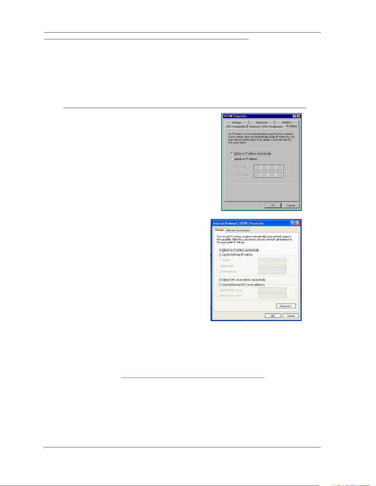
c. Windows Vista and Windows 7 are set to obtain an IP address automatically by default. You may not need to
configure them at all.
To check, open the Networking Control Panel and select Internet Protocol Version 4 (TCP/IPv4). Click the
Properties button.
The Internet Protocol Version 4 (TCP/IPv4) Properties window should appear as shown.
If not, select the radio buttons shown above, and click the OK button.
12
Page 13

Macintosh MacOS 9.2 and higher or Mac OS X 10.1.5 or higher:
1. Access the TCP/IP or Network control panel.
a. MacOS follows a path
like this:
b. Mac OS X
follows a path
like this:
Apple Menu -> Control Panels -> TCP/IP Control Panel
Apple Menu -> System Preferences ->
Network ->
Configure
Then go to Step 2.
2. Select Built-in Ethernet
3. Select Configure IPv4: Using DHCP
4. Close and Save, if prompted.
Proceed to the next section “Motorola Netopia® Gateway Quickstart” on page 14.
13
Page 14

Administrator’s Handbook
Motorola Netopia® Gateway Quickstart
1. Run a Web browser, such as Mozilla Firefox or Microsoft Internet Explorer.
Enter http://192.168.1.254 in the URL Address text box.
Press Return.
(If your ISP’s Configuration Worksheet tells you to use an IP address other than 192.168.1.254 to log in, enter
http://< ip-address>.)
2. The browser displays the Welcome page.
◆ You can choose Unrestricted LAN Access.
If you choose Unrestricted LAN Access, any user connected to your network can access and administer the
Motorola Netopia
Or,
®
Gateway’s configuration pages.
◆ For security, you may create and enter an Administrative password for accessing the Motorola Netopia
way.
• The administrative User name is admin.
• The initial Password can be whatever you choose, from one to 32 characters long.
This user name and password are separate from the user name and password you might use to access the
Internet. You may change them later. You will be challenged for this Admin username and password any time
that you attempt to access the Motorola Netopia
®
Gateway’s configuration pages.
14
®
Gate-
Page 15

If you have chosen to create an Administrative password, when you connect to your Gateway as an Administrator, you enter “admin” as the UserName and the Password you just created.
3. Click OK.
Congratulations! Your installation is complete. You can now surf to your favorite Web sites by typing an URL in
your browser’s location box or by selecting one of your favorite Internet bookmarks. Optional services that you
may have contracted with your provider are also available.
If you have any questions or encounter problems with your Motorola Netopia
®
Gateway, refer to “Basic Trouble-
shooting” on page 45, the context-sensitive help in your Gateway’s web pages, or contact your service pro-
vider’s technical support helpdesk.
Answers to many frequently asked product-related questions are also available on-line at:
http://broadband.motorola.com/consumers/support/default.asp?supportSection=blank
If you click the Back button on your web browser, the browser displays the Basic Home Page.
15
Page 16

Administrator’s Handbook
16
Page 17

CHAPTER 2 Web-based Device Management
Using the Web-based user interface for the Motorola Netopia® Gateway you can configure, troubleshoot, and
monitor the status of your Gateway.
◆ “The Home Page” on page 18
◆ “Links Bar” on page 19
◆ “Configure” on page 20
◆ “Status” on page 35
◆ “Utilities” on page 39
◆ “Help” on page 44
17
Page 18

Administrator’s Handbook
The Home Page
Home Page for a Wi-Fi model
Home Page Information
The Home page displays information about the following categories:
◆ Connection Information
◆ Router Information
◆ Local Network
◆ Restart Connection – For a PPPoE connection, clicking this button will bring down any PPPoE WAN connec-
tion that is up and resend your current PPPoE login credentials and reestablish your Internet connection.
For a DHCP connection, clicking this button will release and renew the DHCP lease from your service provider’s DHCP server, which assigns your local WAN IP address.
◆ Connect – Only displays if you are not connected. For a PPPoE connection, clicking this button will allow you
to attempt to login using a different User ID and Password.
◆ Disconnect – Only for a PPPoE connection, clicking this button will disconnect you from the Internet until you
choose to reestablish your connection manually.
Click the
for every page in the Web interface. See
Help link in the left-hand column of links to display a page of explanatory information. Help is available
“Help” on page 44.
18
Page 19

Links Bar
The links in the left-hand column of the Home page access a series of pages to allow you to monitor, diagnose,
and update your Gateway. The following sections give brief descriptions of these pages.
◆“The Home Page” on page 18
◆“Configure” on page 20
◆“Status” on page 35
◆“Utilities” on page 39
◆“Help” on page 44
19
Page 20

Administrator’s Handbook
Configure
When you click Configure in the left hand column of links, the links bar expands.
◆“Connection” on page 21
◆“DHCP Server” on page 23
◆“More IP Subnets” on page 24
◆“Wireless” on page 25
◆“NAT” on page 31
◆“Router Password” on page 33
◆“Time Zone” on page 34
20
Page 21

Connection
When you click Connection, the Connection Configuration page appears. This screen’s appearance will vary
depending on your type of connection to the Internet.
Here is an example.
Here you can set up or change the way you connect to your ISP. You should only change these settings at your
ISP's direction, or by agreement with your ISP.
◆ DSL Auto Modulation: provides automatic rate adaptation which tries to sync at the fastest possible modula-
tion.
◆ DSL Transport: Select ATM (Asynchronous Transfer Mode), PTM (Packet Transfer Mode), AUTO, or NONE
from the pull-down menu. These modes depend on the equipment used by your ISP. Many providers now support dual mode IP DSLAM line cards that default to PTM, with ATM as a fallback. The default AUTO allows the
best compatibility.
◆ Auto Detection VPI/VCI: If this checkbox is checked, your Gateway will attempt to detect the virtual circuit
pairs in use by trying the most common ones in succession until one is found. Thereafter, the Gateway will
always attempt to use that pair. If it cannot detect the VPI/VCI set in use, you can uncheck the checkbox, and
enter the values manually.
◆ VPI/VCI: These values depend on the way your ISP's equipment is configured. 0/35 and 8/35 are the most
common virtual circuit pairs, but others are also used.
◆ Encapsulation: The authentication and encapsulation protocol is determined by your ISP by the type of
account that you have signed up for and the model of your Motorola device. Choose from the pull-down menu:
pppoe-llc, pppoe-vcmux, ether-llc, ip-llc, pppoa-llc, or pppoa-vcmux
◆ Bridging: Your Gateway can be turned into a simple bridge, if desired. Select Enabled from the pull-down
menu. However, it will no longer provide routing or security features in this mode.
◆ Use Static IP Addressing: Your service provider may tell you that the WAN IP Address for your Gateway is
static. In this case, check the checkbox.
21
Page 22

Administrator’s Handbook
◆ The screen expands to allow you to enter the Static IP Address and Netmask from your Service Provider in
the appropriate fields.
◆ IP Gateway: The IP Address of the default gateway, or peer address if using PPP. This is normally set to
0.0.0.0 for PPP connections.
◆ Primary DNS Server: The IP Address of the Primary Domain Name Server
◆ Secondary DNS Server: The IP Address of the backup Domain Name Server
When all of your entries are made, click the
Apply Changes button.
22
Page 23

DHCP Server
When you click DHCP Server, the DHCP Server Configuration page appears.
The Server configuration determines the functionality of your DHCP Settings. This functionality enables the Gateway to assign your LAN computer(s) a “private” IP address and other parameters that allow network communication. This feature simplifies network administration because the Gateway maintains a list of IP address
assignments. Additional computers can be added to your LAN without the hassle of configuring an IP address.
This is the default mode for your Gateway.
◆ Router IP Address: Specifies the IP address of the Gateway itself.
◆ Subnet Mask: Specifies the subnet for DHCP clients on the LAN side of the gateway. Defaults to the common
Class C subnet.
◆ DHCP Server Enable: Uncheck this setting if you already have a DHCP server on your LAN. This enables the
DHCP server in this Gateway.
◆ DHCP Start Address: Specifies the first address in the DHCP address range. You can reserve a sequence of
up to 253 IP addresses within a subnet, beginning with the specified address, for dynamic assignment.
◆ DHCP End Address: Specifies the last address in the DHCP address range.
◆ DHCP Lease: Specifies the default length for DHCP leases issued by the Gateway. Enter lease time in
dd:hh:mm:ss (days/hours/minutes/seconds) format.
23
Page 24

Administrator’s Handbook
More IP Subnets
When you click the More IP Subnets link, the Additional IP Subnets screen appears.
One subnet is preconfigured by default. The Additional IP Subnets screen allows you to configure up to seven
secondary subnets and their DHCP ranges, by entering IP address/subnet mask pairs:
☛ Note:
You need not use this screen if you have only a single Ethernet IP subnet.
◆ To add an IP subnet, enter the Gateway’s IP address on the subnet in the IP Address field and the subnet
mask for the subnet in the Netmask field.
◆ Enter the DHCP Start Address and End Address of the subnet range in their respective fields.
Ranges cannot overlap and there may be only one range per subnet.
If DHCP Server (see “DHCP Server” on page 23) is not enabled, the DHCP Start Address and DHCP End
Address fields do not appear.
◆ Click the Add this IP Subnet button. Your entries will be added to the IP Subnet List.
To Edit or Remove a configured subnet, click the respective icon in the list item. When you are finished, click the
Apply Changes button.
24
Page 25

Wireless
(supported models)
When you click the
Wireless link in the links bar, the menu expands.
Wireless Configuration
When you click the Base Settings link, the Wireless Base Settings page appears.
◆ The wireless function is automatically enabled by default. If you uncheck the Enabled checkbox, the wireless
options are disabled, and the Gateway will not provide or broadcast its wireless LAN services.
◆ The pull-down menu allows you to select and lock the Gateway into the wireless transmission mode you want:
B/G B-only
G-only B/G/N
N-only A/N
A-only
For compatibility with clients using 802.11b (up to 11 Mbps transmission), 802.11g (up to 20+ Mbps), 802.11a
(up to 54 Mbit/s using the 5 GHz band), or 802.11n (from 54 Mbit/s to 600 Mbit/s with the use of four spatial
streams at a channel width of 40 MHz), select B/G/N. To limit your wireless LAN to one mode or the other,
select G-only
, N-only, A-only, or B-only, or some combination that applies to your setup.
25
Page 26

Administrator’s Handbook
☛ NOTE:
If you choose to limit the operating mode to G-only
mode(s) you excluded will not be able to connect.
◆ Channel – (1 through 11, for North America) on which the network will broadcast. This is a frequency range
within the 2.4Ghz band. Channel selection depends on government regulated radio frequencies that vary from
region to region. The widest range available is from 1 to 14. Europe, France, Spain and Japan differ. Channel
selection can have a significant impact on performance, depending on other wireless activity close to this
Router. Channel selection is not necessary at the client computers; the clients will scan the available channels
seeking access points using the same SSID as the client.
◆ Wireless Protected Setup (WPS) is a not a new security protocol. It is simply an easier way to use existing
protocols to provide greater security for your wireless network connections.
By default, Privacy is set to Wireless Protected Access (WPA-PSK). WPS allows you to automatically
generate a new strong WPA key for your Gateway and any client devices on your wireless network.
, N-only, A-only, or B-only, clients using the
☛ Note:
Not all client wireless devices support WPS. Refer to their documentation.
Wireless Security
When you click the Security link, the Wireless Security page appears.
YOU ARE STRONGLY ENCOURAGED TO IMPLEMENT SOME FORM OF PRIVACY ON YOUR WIRELESS
LAN. You can specify the Privacy mode for each SSID that you define. Options from the pull-down menu are:
◆ OFF– No Privacy
◆ WEP–Manual - see “WEP Manual” on page 27
◆ WPA-PSK - see “WPA-PSK” on page 28
Hide SSID. If you check this checkbox, the Gateway hides the wireless network from the scanning features of
wireless client computers. Unless both the wireless clients and the Gateway share the same Wireless ID in this
mode, the Gateway’s wireless LAN will not appear as an available network when scanned for by wireless-enabled
computers. Members of this “Closed System” WLAN must log onto the Gateway’s wireless network with the identical SSID as that configured in the router.
Closed System mode is an ideal way to increase wireless security and to prevent casual detection by unwanted
neighbors, office users, or malicious users such as hackers.
If you do not enable this mode, it is more convenient, but potentially less secure, for clients to access your WLAN
by scanning available access points. You must decide based on your own network requirements.
26
Page 27

Enabling Closed System Mode on your wireless Gateway provides another level of security, since your wireless
LAN will no longer appear as an available access point to client PCs that are casually scanning for one.
Your own wireless network clients, however, must log into the wireless LAN by using the exact SSID of the Motorola Netopia
In addition, if you have enabled WEP or WPA encryption on the Motorola Netopia® Gateway, your network clients
must also have WEP or WPA encryption enabled, and must have the same WEP or WPA encryption key as the
Motorola Netopia
Once the Motorola Netopia
client can connect immediately if WEP or WPA is not enabled. If WEP or WPA is enabled then the client must also
have WEP or WPA enabled and a matching WEP or WPA key.
Wireless client cards from different manufacturers and different operating systems accomplish connecting to a
wireless LAN and enabling WEP or WPA in a variety of ways. Consult the documentation for your particular wireless card and/or operating system.
®
Gateway.
®
Gateway.
®
Gateway is located by a client computer, by setting the client to a matching SSID, the
Block Wireless Bridging. Check the checkbox to block wireless clients from communicating with other wire-
less clients on the LAN side of the Gateway.
WEP Manual
WEP (Wired Equivalent Privacy) Security is a Privacy option that is based on encryption between the Router and
any PCs (“clients”) you have with wireless cards. If you are not using WPA-PSK Privacy, you can use WEP
encryption instead. For this encryption to work, both your Router and each client must share the same Wireless
ID, and both must be using the same encryption keys.
You can provide a level of data security by enabling WEP (Wired Equivalent Privacy) for encryption of network
data. You can enable 40-, 128-, or 256-bit WEP Encryption (depending on the capability of your client wireless
card) for IP traffic on your LAN.
WEP - Manual allows you to enter your own encryption keys manually. This is a difficult process, but only needs to
be done once. Avoid the temptation to enter all the same characters.
◆ Key Length: Selects the length of each encryption key. The longer the key, the stronger the encryption and the
more difficult it is to break the encryption.
◆ Key: The encryption keys. You enter keys using hexadecimal digits. For 40/64bit encryption, you need ten dig-
its; 26 digits for 128bit WEP. Hexadecimal characters are 0 – 9, and a – f.
Examples:
• 40bit: 02468ACE02
• 128bit: 0123456789ABCDEF0123456789
Click the click Apply Changes button.
27
Page 28

Administrator’s Handbook
Any WEP-enabled client must have an identical key of the same length as the Gateway, in order to successfully
receive and decrypt the traffic. Similarly, the client also has a ‘default’ key that it uses to encrypt its transmissions.
In order for the Gateway to receive the client’s data, it must likewise have the identical key of the same length.
WPA-PSK
One of the easiest ways to enable Privacy on your Wireless network is by selecting WPA-PSK (Wi-Fi Protected
Access) from the pull-down menu.
◆ Enter a Passphrase. The key can be between 8 and 63 characters, but for best security it should be at least
20 characters.
◆ You also have the choice of applying Both WPA Version 1 and 2, WPA Version 1 Only, or WPA Version 2
Only from the pull-down menu. These can be applied to each SSID individually.
When you have finished, click the
Apply Changes button.
Wireless Multiple SSIDs
This feature allows you to add additional network identifiers (SSIDs or Network Names) for your wireless network.
To enable Multiple SSIDs, click the
The Wireless Multiple IDs screen appears to allow you to add up to three additional Wireless IDs.
Multiple SSID link.
◆ When the Multiple Wireless SSIDs screen appears, check the SSID Enable checkbox for each SSID you want
to enable.
◆ The screen allows you to name each additional Wireless ID.
When you have finished, click the
Apply Changes button.
28
Page 29

Wireless Multi-media Configuration
Wireless Multi-media is an advanced feature that allows you to prioritize various types of data travelling over the
wireless network. Certain types of data that are sensitive to delays, such as voice or video, must be prioritized
ahead of other, less delay-sensitive types, such as email.
Wireless Multi-media currently implements wireless Quality of Service (QoS) by transmitting data depending on
Diffserv priority settings. These priorities are mapped into four Access Categories (AC), in increasing order of priority:
◆ Background (BK),
◆ Best Effort (BE),
◆ Video (VI), and
◆ Voice (VO).
It requires WiFi Multimedia (WMM)-capable clients, usually a separate feature enabled at the client network settings, and client PC software that makes use of Differentiated Services (Diffserv). Refer to your operating system
instructions for enabling Diffserv QoS.
When you click the
Check the Enabled checkbox and click the
WiFi Multimedia link the Wireless Multi-media Configuration page appears.
Apply Changes button.
Wireless MAC Filtering
When you click the MAC Filtering link the Wireless MAC Filtering page appears.
MAC Filtering allows you to specify which client PCs are allowed to join the wireless LAN by unique hardware
(MAC) address.
◆ To enable this feature, select either whitelist or blacklist from the MAC Filtering Type pull-down menu.
29
Page 30

Administrator’s Handbook
◆ You add wireless clients that you want to either authorize or exclude for your wireless LAN by entering the
MAC addresses in the MAC Address field provided.
Click the
Your entries will be added to a client MAC Filter List.
Add this MAC button.
Click the
You can Add more entries or Remove any of your entries later by returning to this page.
Apply Changes button.
30
Page 31

NAT
When you click NAT, the NAT Configuration page appears.
◆ NAT Configuration allows you to host internet applications when NAT is enabled. You can host different
games and software on different PCs.
◆ Pinhole Entry allows you to transparently route selected types of network traffic, such as FTP requests or
HTTP (Web) connections, to a specific host behind the Gateway. Creating a pinhole allows access traffic originating from a remote connection (WAN) to be sent to the internal computer (LAN) that is specified in the Pinhole page.
Pinholes are common for applications like multiplayer online games. Refer to software manufacturer application documentation for specific traffic types and port numbers.
◆ Determine if any of the service applications that you want to provide on your LAN stations use TCP or UDP
protocols. If an application does, then you must configure a pinhole to implement port forwarding.
• Protocol: UDP or TCP
• External Port Range: This is the range of ports on which you expect incoming traffic to be received.
• Internal Address: This is the internal host IP address to which you want the traffic to be directed.
• Internal Start Port: This is the port number at the start of the port range that you want your Gateway to use
when forwarding traffic of the type(s) you have selected to the internal IP address.
31
Page 32

Administrator’s Handbook
The following example shows three pinholes:
◆ a web server (using TCP on port 80, the standard HTTP protocol web port) on a host at the internal IP address
192.168.1.1
◆ a mail server (using TCP on port 25, the standard SMTP protocol email port) at the internal IP address
192.168.1.2
◆ a games server (using UDP on a port range 1100 – 1200) at the internal IP address 192.168.1.3
You can edit or delete any of your entries from the Pinhole List by clicking the
You can add more entries to the Pinhole List by clicking the
When you are finished, click the
Apply Changes button.
Add this pinhole button.
32
Edit or Remove icons.
Page 33

Router Password
When you click Router Password, the Router Password page appears.
Here you can change the administrative password that you use when logging onto the Gateway as admin. Passwords are case sensitive fields, and must be 1 to 32 characters long. Store your password in a safe place. Enter
your new password, and confirm it.
◆ You can choose Unrestricted LAN Access.
If you choose Unrestricted LAN Access, any user connected to your network can access and administer the
Motorola Netopia
Or,
◆ For security, you may create and enter an Administrative password for accessing the Motorola Netopia
way.
• The administrative User name is admin.
• The Password can be whatever you choose, from one to 32 characters long.
You will be challenged for this Admin username and password any time that you attempt to access the Motor-
ola Netopia
®
Gateway’s configuration pages.
®
Gateway’s configuration pages.
®
Gate-
Click the
Apply Changes button.
33
Page 34

Administrator’s Handbook
Time Zone
When you click the Time Zone link, the Time Zone page appears.
You can set your local time zone by selecting your time zone from the pull-down menu. This allows you to set the
time zone for general time stamp purposes.
Click the Apply Changes button.
Changes are saved immediately.
34
Page 35

Status
When you click Status in the left hand column of links, the links bar expands.
Available Status links vary by platform.
DSL
When you click DSL, the DSL Statistics page appears.
The DSL Statistics page displays information about the Gateway's WAN connection to the Internet.
◆ Line State: May be Up (connected) or Down (disconnected).
◆ Modulation: Method of regulating the DSL signal. DMT (Discrete MultiTone) allows connections to work better
when certain radio transmitters are present.
◆ Data Path: Type of path used by the device's processor.
Downstream and Upstream statistics
◆ Max Allowed Speed (kbps): Your maximum speeds for downloading (receiving) and uploading (sending) data
on the DSL line, in kilobits per second.
◆ SN Margin (db): Signal to noise margin, in decibels. Reflects the amount of unwanted “noise” on the DSL line.
◆ Line Attenuation: Amount of reduction in signal strength on the DSL line, in decibels.
◆ CRC Errors: Number of times data packets have had to be resent due to errors in transmission or reception.
WAN
When you click WAN , the WAN Statistics page appears.
The WAN Statistics page:
◆ displays detailed statistics about your WAN data traffic, upstream and downstream.
◆ displays the Server MAC address for the PPPoE session (if applicable)
This information is useful for troubleshooting and when seeking technical support.
35
Page 36

Administrator’s Handbook
Ethernet
When you click Ethernet, the Ethernet Statistics page appears.
The Ethernet Statistics page:
◆ displays your Gateway's unique hardware (MAC) address.
◆ displays detailed statistics about your LAN data traffic, upstream and downstream.
Wireless
When you click Wireless, the Wireless Statistics page appears.
◆ Wireless Status: displays the enabled wireless SSIDs and their security (privacy) settings
◆ Wireless Statistics: displays both bytes and packets received and transmitted.
IP
When you click IP, the IP Statistics page appears. The IP Statistics page displays the IP interfaces and routing
table information about your network.
General
◆ IP WAN Address: The public IP address of your Gateway, whether dynamically or statically assigned.
◆ IP Gateway: Your ISP's gateway Gateway IP address
◆ Primary DNS: The IP address of the Primary Domain Name Server
◆ Primary DNS name: The name of the Primary Domain Name Server
◆ Secondary DNS: The IP address of the backup Domain Name Server (if any)
◆ Secondary DNS name: The name of the backup Domain Name Server
IP interfaces
◆ Address: Your Gateway's IP address as seen from your internal network (LAN), and from the public Internet
(WAN)
◆ Netmask: The subnet mask for the respective IP interfaces (LAN and WAN)
◆ Name: The name of each IP interface (example:Eth0, WAN2)
Network Routing Table and Host Routing Table
The Routing tables display all of the IP routes currently known to your Gateway
LAN
When you click LAN, the LAN Statistics page appears.
The LAN Statistics page displays detailed information about your LAN IP configuration and names and IP
addresses of devices on your LAN.
◆ Gateway IP Address: The IP address of your Gateway as seen from the LAN
◆ DHCP Netmask: Subnet mask of your LAN
◆ DHCP Start Address: First IP address in the range being served to your LAN by the Gateway's DHCP server
◆ DHCP End Address: Last IP address in the range being served to your LAN by the Gateway's DHCP server
◆ DHCP Server Status: May be On or Off
◆ DNS Server: The IP address of the default DNS server
Devices on LAN
Displays the IP Address, MAC (hardware) Address, and network Name for each device on your LAN connected to
the Gateway.
36
Page 37

System Log
When you click System Log, the System Log page appears.
The current status of the Gateway is displayed for all logs.
◆ You can clear all log entries by clicking the Clear Log button.
◆ You can save logs to a text (.TXT) file by clicking the Save to File button. This will download the file to your
browser’s default download location on your hard drive. The file can be opened with your favorite text editor.
☛ Note:
Some browsers, such as Internet Explorer for Windows XP, require that you specify the Motorola
Netopia
allow the “download” of the log text file to the PC.
®
Gateway’s URL as a “Trusted site” in “Internet Options: Security”. This is necessary to
37
Page 38

Administrator’s Handbook
Firewall Log
When you click Firewall Log, the Firewall Log page appears.
The Gateway detects security related events including common types of malicious attacks and writes them to a
dedicated Firewall log file. You view this log file from either:
◆ Motorola Netopia
◆ Text-based command line interface using telnet
®
Web interface
The log provides information useful in identifying a specific type of attack and tracing its origin. The log maintains
100 entries, and requires a manual reset once full. This preserves for troubleshooting purposes the acquired information about specific attacks, their frequency and tracing information.
38
Page 39

Utilities
When you click the Utilities link, the linksbar expands to display the Gateway’s diagnostic and update utilities.
◆“Diagnostics” on page 40
◆“Restart Router” on page 42
◆“Reset Router” on page 42
◆“Update Router” on page 43
39
Page 40

Administrator’s Handbook
Diagnostics
When you click Diagnostics, the Diagnostics page appears.
This automated multi-layer test examines the functionality of the Gateway from the physical connections to the
data traffic being sent by users through the Gateway.
Run Full Diagnostics section tests a number of different things at the same time, including the DSL line,
The
the Ethernet interface and the PPPoE session.
This sequence of tests takes approximately one minute to generate results. Please wait for the test to run to completion.
40
Page 41

Test Web Access
You enter a web address URL or an IP address in the Web Address field and click the Test button. Results will be
displayed in the Progress Window as they are generated.
Example:
==== Checking LAN Interfaces
Check Ethernet LAN connect : PASS
Check IP connect to Ethernet (LAN) : PASS
Pinging Gateway : PASS
Check MAC-Bridge connect to Ethernet (LAN) : PASS
==== Checking DSL (WAN) Interfaces
Check DSL Synchronization : PASS
Check ATM Cell-Delineation : PASS
ATM OAM Segment Ping through (vcc1) : WARNING
*** Don't worry, your service provider may not support this test
ATM OAM End-To-End Ping through (vcc1) : WARNING
*** Don't worry, your service provider may not support this test
Check Ethernet connect to AAL5 (vcc1) : PASS
Check PPPOE connect to Ethernet (vcc1) : PASS
Check PPP connect to PPPOE (vcc1) : PASS
Check IP connect to PPP (vcc1) : PASS
Pinging Gateway : PASS
==== Checking Miscellaneous
Check DNS- Query for netopia.com : SKIPPED
Ping DNS Server Primary IP Address : SKIPPED
TEST DONE
Each test generates one of the following result codes:
Result Meaning
* PASS: The test was successful.
* FAIL: The test was unsuccessful.
* SKIPPED: The test was skipped because a test on which it depended failed.
* PENDING: The test timed out without producing a result. Try running Diagnostics again.
* WARNING: The test was unsuccessful. The Service Provider equipment your Gateway
connects to may not support this test.
41
Page 42

Administrator’s Handbook
Restart Router
When the Gateway is restarted, it will disconnect all users, initialize all its interfaces, and copy the Operating System Software from its internal storage.
When you make configuration changes, you must restart for the changes to take effect.
Reset Router
You might need to reset your Gateway to its factory default state, and clear all of your previous settings. The
Reset Router link allows you to do that. When you click the link, you will be challenged to confirm that this is
what you want to do.
If you want to clear your settings, click the
will be reset to the factory default. Any configuration information you have entered will be lost and will have to be
re-entered. The Gateway will automatically restart.
Yes, reset to factory settings button. The Gateway configuration
42
Page 43

Update Router
When you click Update Router, the Software Upgrade page appears.
Operating System Software is what makes your Gateway run and occasionally it needs to be updated. Your Cur-
rent Software Version is displayed at the top of the page.
To update your software from a file on your PC, you must first download the software.
1. Click the Click here to download link.
You will be taken to the Motorola website for software upgrades.
2. If an upgrade exists, download it to your computer.
3. Browse your computer for the operating system file you downloaded.
4. Click the Update Software from PC button.
5. The install may take a few minutes; wait for it to complete.
6. Restart your Gateway and your new operating system will be running.
43
Page 44

Administrator’s Handbook
Help
Click the Help link in the left-hand column of links to display a page of explanatory information. Help is available
for every page in the Web interface.
Here is an example:
44
Page 45

CHAPTER 3 Basic Troubleshooting
This section gives some simple suggestions for troubleshooting problems with your Gateway’s initial configuration.
Before troubleshooting, make sure you have
◆ read the User Manual;
◆ plugged in all the necessary cables; and
◆ set your PC’s TCP/IP controls to obtain an IP address automatically.
45
Page 46

Administrator’s Handbook
Status Indicator Lights
The first step in troubleshooting is to check the status indicator lights (LEDs) in the order outlined in the following
section.
Motorola Netopia®
Front View
Gateway 2247-N8 status indicator lights
Power
Ethernet 1, 2, 3, 4
Wireless
WPS
LED Behavior
Power
Ethernet
Green when power is on. Red if device malfunctions; flashes red when updating
embedded software.
Solid green when connected. Flash green when there is activity on the LAN.
1, 2, 3, 4
Wireless
WPS
USB
DSL
Internet
Flashes green when there is activity on the wireless LAN.
Solid green when WPS is successful.
Not currently used.
Flashes green when training. Solid green when trained.
Green when device is connected. Flashes green for activity on WAN port.
USB
Activity
Internet
DSL
46
Activity
Off = The device is not powered or the broadband connection is not present;
Flashing green = Inbound Internet activity seen from the broadband connection
Page 47

LED Function Summary Matrix
Power DSL Internet
Unlit No power No signal Not connected
Solid Green Power on DSL line synched with the
DSLAM
Flashing Green N/A Activity on the DSL cable Transmitting or receiving
Solid Red System malfunction N/A N/A
Flashing Red Updating embedded soft-
ware
N/A N/A
Ethernet 1, 2, 3, 4 WPS Wireless
Unlit No signal No wireless signal No wireless signal
Solid Green Synched with Ethernet
card
Flashing Green Activity on the Ethernet
cable
Solid Red N/A N/A N/A
Flashing Red N/A N/A N/A
WPS exchange with
client is successful
N/A Activity on the wireless
Connected to the Internet
data on the WAN port
N/A
LAN
If a status indicator light does not look correct, look for these possible problems:
If LED is
not Lit
Possible problems
◆ Make sure the power switch is in the ON position.
Power
◆ Make sure the power adapter is plugged into the DSL Gateway properly.
◆ Try a known good wall outlet.
◆ Replace the power supply and/or unit.
◆ Make sure that any telephone has a microfilter installed.
◆ Make sure that you are using the correct cable. The DSL cable is the thinner stan-
dard telephone cable.
DSL
◆ Make sure the DSL cable is plugged into the correct wall jack.
◆ Make sure the DSL cable is plugged into the DSL port on the DSL Gateway.
◆ Make sure the DSL line has been activated at the central office DSLAM.
◆ Make sure the DSL Gateway is not plugged into a micro filter.
47
Page 48

Administrator’s Handbook
◆ Make sure the you are using the Ethernet cable, not the DSL cable. The Ethernet
◆ Make sure the Ethernet cable is securely plugged into the Ethernet jack on the PC.
◆ Make sure the Ethernet cable is securely plugged into the Ethernet port on the DSL
◆ Try another Ethernet cable if you have one available.
Ethernet
◆ Make sure you have Ethernet drivers installed on the PC.
◆ Make sure the PC’s TCP/IP Properties for the Ethernet Network Control Panel is set
◆ Make sure the PC has obtained an address in the 192.168.1.x range. (You may have
◆ Make sure the PC is configured to access the Internet over a LAN.
◆ Disable any installed network devices (Ethernet, HomePNA, wireless) that are not
cable is thicker than the standard telephone cable.
Gateway.
to obtain an IP address via DHCP.
changed the subnet addressing.)
being used to connect to the DSL Gateway.
48
Page 49

Factory Reset Switch
Lose your password? This section shows how to reset the Motorola Netopia® so that you can access the configuration screens once again.
☛ NOTE: Keep in mind that all of your settings will need to be reconfigured.
If you don't have a password, the only way to access the Motorola Netopia® is the following:
1. Referring to the following diagram, find the round Reset Switch opening.
Factory Reset Switch
2. Carefully insert the point of a pen or an unwound paperclip into the opening.
• If you press the factory default button for less than 1/2 a second, the unit will continue to run as normal.
• If you press the factory default button for 1 – 3 seconds, when you release it, the Gateway will perform a factory reset, clear all settings and configurations, and reboot. Do not hold the button down too long (5 – 10 seconds). This will destroy any saved default settings as well.
49
Page 50

Administrator’s Handbook
50
Page 51

CHAPTER 4 Command Line Interface
The Motorola Netopia® Gateway operating software includes a command line interface (CLI) that lets you access
your Motorola Netopia® Gateway over a telnet connection. You can use the command line interface to enter and
update the unit’s configuration settings, monitor its performance, and restart it.
This chapter covers the following topics:
◆ “Overview” on page 52
◆ “Starting and Ending a CLI Session” on page 54
◆ “Using the CLI Help Facility” on page 54
◆ “About SHELL Commands” on page 55
◆ “SHELL Commands” on page 56
◆ “About CONFIG Commands” on page 64
◆ “CONFIG Commands” on page 67
CONFIG Commands
“Connection commands” on page 67
“IP DNS commands” on page 68
“IP IGMP commands” on page 69
“NTP commands” on page 71
“IP Gateway commands” on page 71
“Application Layer Gateway (ALG) commands” on page 72
“Link commands” on page 72
“Management commands” on page 73
“Physical interfaces commands” on page 74
“PPPoE relay commands” on page 76
“NAT Pinhole commands” on page 77
“System commands” on page 78
51
Page 52

Administrator’s Handbook
Overview
The CLI has two major command modes: SHELL and CONFIG. Summary tables that list the commands are provided below. Details of the entire command set follow in this section.
SHELL Commands
Command Status and/or Description
arp to send ARP request
atmping to send ATM OAM loopback
clear to erase all stored configuration information
clear_certificate to remove an SSL certificate that has been installed
clear_log to erase all stored log info in flash memory
configure to configure unit's options
diagnose to run self-test
download to download config file
exit to quit this shell
help to get more: “help all” or “help help”
install to download and program an image into flash
log to add a message to the diagnostic log
loglevel to report or change diagnostic log level
netstat to show IP information
nslookup to send DNS query for host
ping to send ICMP Echo request
quit to quit this shell
reset to reset subsystems
restart to restart unit
show to show system information
start to start subsystem
status to show basic status of unit
telnet to telnet to a remote host
traceroute to send traceroute probes
upload to upload config file
view to show configuration information
who to show who is using the shell
52
Page 53

CONFIG Commands
Command Verbs Status and/or Description
delete Delete configuration list data
help Help command option
save Save configuration data
script Print configuration data
set Set configuration data
validate Validate configuration settings
view View configuration data
Keywords
conn Connection options
ip TCP/IP protocol options
dns Domain Name System options
igmp IGMP configuration options
ntp Network Time Protocol options
gateway Gateway options
link WAN link options
mgmt System management options
phy Physical interface options
dsl DSL configuration options
enet Ethernet options
pinhole Pinhole options
system Gateway’s system options
log System activity logging options
Command Utilities
top Go to top level of configuration mode
quit Exit from configuration mode; return to shell mode
exit Exit from configuration mode; return to shell mode
53
Page 54

Administrator’s Handbook
Starting and Ending a CLI Session
Open a telnet connection from a workstation on your network.
You initiate a telnet connection by issuing the following command from an IP host that supports telnet, for exam-
ple, a personal computer running a telnet application such as NCSA Telnet.
telnet <
You must know the IP address of the Motorola Netopia® Gateway before you can make a telnet connection to it.
By default, your Motorola Netopia® Gateway uses 192.168.1.254 as the IP address for its LAN interface. You can
use a Web browser to configure the Motorola Netopia® Gateway IP address.
Logging In
The command line interface log-in process emulates the log-in process for a UNIX host. To logon, enter the username and your password.
Entering the administrator password lets you display and update all Motorola Netopia® Gateway settings.
When you have logged in successfully, the command line interface lists the username and the security level associated with the password you entered in the diagnostic log.
Ending a CLI Session
You end a command line interface session by typing quit from the SHELL node of the command line interface
hierarchy.
ip_address
>
Using the CLI Help Facility
The help command lets you display on-line help for SHELL and CONFIG commands. To display a list of the commands available to you from your current location within the command line interface hierarchy, enter
type a question mark (
To obtain help for a specific CLI command, type
h
or a question mark when you request help for a CLI command.
?).
help <command>. You can truncate the
help
command to
help or
54
Page 55

About SHELL Commands
You begin in SHELL mode when you start a CLI session. SHELL mode lets you perform the following tasks with
your Motorola Netopia® Gateway:
◆ Monitor its performance
◆ Display and reset Gateway statistics
◆ Issue administrative commands to restart Motorola Netopia® Gateway functions
SHELL Prompt
When you are in SHELL mode, the CLI prompt is the name of the Motorola Netopia® Gateway followed by a right
angle bracket (>). For example, if you open a CLI connection to the Motorola Netopia® Gateway named “Netopia-
3000/9437188,” you would see
SHELL Command Shortcuts
You can truncate most commands in the CLI to their shortest unique string. For example, you can use the truncated command
the
reset
q
in place of the full
command, since the first characters of
Netopia-3000/9437188>
quit
command to exit the CLI. However, you would need to enter
reset
are common to the
as your CLI prompt.
restart
command.
rese
for
The only commands you cannot truncate are
cations, you must enter the
You can use the Up and Down arrow keys to scroll backward and forward through recent commands you have
entered. Alternatively, you can use the
restart
and
restart
clear
!!
command to repeat the last command you entered.
and
clear
. To prevent accidental interruption of communi-
commands in their entirety.
55
Page 56

Administrator’s Handbook
SHELL Commands
Common Commands
arp nnn.nnn.nnn.nnn
Sends an Address Resolution Protocol (ARP) request to match the
Ethernet hardware address.
nnn.nnn.nnn.nnn
IP address to an
clear [ yes ]
Clears the configuration settings in a Motorola Netopia® Gateway. You are prompted to confirm the clear command by entering yes.
clear_certificate
Removes an SSL certificate that has been installed.
configure
Puts the command line interface into Configure mode, which lets you configure your Motorola Netopia® Gateway
with Config commands. Config commands are described starting on
page 67.
download [ server_address ] [ filename ] [ confirm ]
This command installs a file of configuration parameters into the Motorola Netopia® Gateway from a TFTP (Trivial
File Transfer Protocol) server. The TFTP server must be accessible on your Ethernet network.
You can include one or more of the following arguments with the download command. If you omit arguments, the
console prompts you for this information.
◆ The
◆ The
◆ If you include the optional confirm keyword, the download begins as soon as all information is entered.
server_address
the Motorola Netopia® Gateway configuration file.
filename
argument identifies the path and name of the configuration file on the TFTP server.
argument identifies the IP address of the TFTP server from which you want to copy
You can also download an SSL certificate file from a trusted Certification Authority (CA), on platforms that support
SSL, as follows:
download [-cert] [server_address ] [filename] [confirm]
install [ server_address ] [ filename ] [ confirm ]
Downloads a new version of the Motorola Netopia® Gateway operating software from a TFTP (Trivial File Transfer
Protocol) server, validates the software image, and programs the image into the Motorola Netopia® Gateway
memory. After you install new operating software, you must restart the Motorola Netopia® Gateway.
The
server_address
pia® Gateway operating software is stored. The
ing software file on the TFTP server.
If you include the optional keyword
form the operation.
argument identifies the IP address of the TFTP server on which your Motorola Neto-
confirm
filename
, you will not be prompted to confirm whether or not you want to per-
argument identifies the path and name of the operat-
56
Page 57

log message_string
Adds the message in the
message_string
argument to the Motorola Netopia® Gateway diagnostic log.
loglevel [ level ]
Displays or modifies the types of log messages you want the Motorola Netopia® Gateway to record. If you enter
the
loglevel command without the optional
rent log level setting.
You can enter the
you want to record. All messages with a level number equal to or greater than the level you specify are recorded.
For example, if you specify loglevel 3, the diagnostic log will retain high-level informational messages (level 3),
warnings (level 4), and failure messages (level 5).
Use the following values for the
loglevel command with the
level
argument:
level
level
argument, the command line interface displays the cur-
argument to specify the types of diagnostic messages
◆ 1 or low – Low-level informational messages or greater; includes trivial status messages.
◆ 2 or medium – Medium-level informational messages or greater; includes status messages that can help
monitor network traffic.
◆ 3 or high – High-level informational messages or greater; includes status messages that may be significant
but do not constitute errors.
◆ 4 or warning – Warnings or greater; includes recoverable error conditions and useful operator informa-
tion.
◆ 5 or failure – Failures; includes messages describing error conditions that may not be recoverable.
netstat -i
Displays the IP interfaces for your Motorola Netopia® Gateway.
netstat -r
Displays the IP routes stored in your Motorola Netopia® Gateway.
nslookup [ hostname | ip_address ]
Performs a domain name system lookup for a specified host.
◆ The
◆ The
hostname
argument is the name of the host for which you want DNS information; for example,
nslookup klaatu
ip_address
DNS information.
argument is the IP address, in dotted decimal notation, of the device for which you want
.
ping [-s size] [-c count ] [ hostname | ip_address ]
Causes the Motorola Netopia® Gateway to issue a series of ICMP Echo requests for the device with the specified
name or IP address.
◆ The
◆ The
◆ The
◆ The
hostname
ping ftp.motorola.com
ip_address
a host using the specified name or IP address is active, it returns one or more ICMP Echo replies, confirming
that it is accessible from your network.
-s
size
-c
count
greater than 250 are truncated to 250.
argument is the name of the device you want to ping; for example,
.
argument is the IP address, in dotted decimal notation, of the device you want to locate. If
argument lets you specify the size of the ICMP packet.
argument lets you specify the number of ICMP packets generated for the ping request. Values
57
Page 58

Administrator’s Handbook
You can use the ping command to determine whether a hostname or IP address is already in use on your network. You cannot use the
ping command to ping the Motorola Netopia® Gateway’s own IP address.
quit
Exits the Motorola Netopia® Gateway command line interface.
reset arp
Clears the Address Resolution Protocol (ARP) cache on your unit.
reset crash
Clears crash-dump information, which identifies the contents of the Motorola Netopia® Gateway registers at the
point of system malfunction.
reset dhcp server
Clears the DHCP lease table in the Motorola Netopia® Gateway.
reset enet [ all ]
Resets Ethernet statistics to zero. Resets individual LAN switch port statistics as well as wireless and WAN Ethernet statistics (where applicable).
reset firewall-log
Rewinds the firewall log to the first entry.
reset ipmap
Clears the IPMap table (NAT).
reset log
Rewinds the diagnostic log display to the top of the existing Motorola Netopia® Gateway diagnostic log. The
reset log command does not clear the diagnostic log. The next show log command will display information
from the beginning of the log file.
reset wan
This function resets WAN interface statistics.
reset wepkeys
This function allows you to force your wireless WEP key settings back to the default values, if there are default values. For example, on some models, the WEP keys are based on the serial number. This allows you to get back
those default settings if you have changed them without the need to reset the entire configuration of the unit.
restart [ seconds ]
Restarts your Motorola Netopia® Gateway. If you include the optional
pia® Gateway will restart when the specified number of seconds have elapsed. You must enter the complete
restart command to initiate a restart.
seconds
argument, your Motorola Neto-
58
Page 59

show all-info
Displays all settings currently configured in the Motorola Netopia® Gateway.
show bridge interfaces
Displays bridge interfaces maintained by the Motorola Netopia® Gateway.
show bridge table
Displays the bridging table maintained by the Motorola Netopia® Gateway.
show config
Dumps the Motorola Netopia® Gateway’s configuration script just as the script command does in config
mode.
show crash
Displays the most recent crash information, if any, for your Motorola Netopia® Gateway.
show daylight-savings
Displays the auto-daylight savings time settings information.
show dhcp agent
Displays DHCP relay-agent leases.
show dhcp server leases
Displays the DHCP leases stored in RAM by your Motorola Netopia® Gateway.
show diffserv
Displays the Differentiated Services and QoS values configured in the Motorola Netopia® Gateway.
show dslf device-association
Displays LAN devices that conform with the TR111 Gateway requirement. It displays - IP Address, Manufacture
OUI and Serial number.
show enet [ all ]
Displays Ethernet interface statistics maintained by the Motorola Netopia® Gateway. Supports display of individual LAN switch port statistics as well as WAN Ethernet statistics (where applicable).
Example:
Ethernet driver full statistics - 10/100 Ethernet
Port Status: Link up
Type: 100BASET Duplex: Full
General:
Transmit OK : 434
59
Page 60

Administrator’s Handbook
Receive OK : 267
Tx Errors : 0
Rx Errors : 0
Receiver:
Incompl Packet Errors : 0
No RBD's For Packet : 0
Carrier Sense Lost : 0
Deferred Replen : 0
Transmitter:
TX Retries : 0
Single Collisions : 0
No Buf For Packet : 0
Upper Layers:
Rx No Handler : 0
Rx No Message : 0
Rx Octets : 30773
Rx Unicast Pkts : 267
Rx Multicast Pkts : 0
Tx Discards : 0
Tx Octets : 31692
10/100 Ethernet phy.enet.port
Port Status: Link up
Duplex: Full-duplex active
Speed: 100BASE-T
Transmit OK : 434
Transmit unicastpkts : NA
Receive OK : 267
Receive unicastpkts : 267
show group-mgmt
Displays the IGMP Snooping Table. See “IP IGMP commands” on page 69 for detailed explanation.
show ip arp
Displays the Ethernet address resolution table stored in your Motorola Netopia® Gateway.
show ip igmp
Displays the contents of the IGMP Group Address table and the IGMP Report table maintained by your Motorola
Netopia® Gateway.
show ip interfaces
Displays the IP interfaces for your Motorola Netopia® Gateway.
show ip firewall
Displays firewall statistics.
60
Page 61

show ip lan-discovery
Displays the LAN Host Discovery Table of hosts on the wired or wireless LAN, and whether or not they are currently online.
show ip routes
Displays the IP routes stored in your Motorola Netopia® Gateway.
show ipmap
Displays IPMap table (NAT).
show log
Displays blocks of information from the Motorola Netopia® Gateway diagnostic log. To see the entire log, you can
repeat the
show log command or you can enter show log all.
show memory [ all ]
Displays memory usage information for your Motorola Netopia® Gateway. If you include the optional
ment, your Motorola Netopia® Gateway will display a more detailed set of memory statistics.
all
argu-
show pppoe
Displays status information for each PPPoE socket, such as the socket state, service names, and host ID values.
show rootcert [ all | supplicant | openssl ]
Dumps the Subject line for the list of all the trusted root certificates for the supplicant, which is currently a superset
of the OpenSSL trusted root certificates.
This syntax is for the 802.1x-supplicant-supported builds only. The openssl trust list is used in all TLS/SSL situations
except the 802.1X supplicant.
The default, if you don't append a qualifier, is all. all will show both 802.1x supplicant and openssl trust list root
certs; supplicant will show the supplicant trust list root certs; openssl will show openssl trust list root certs
show rtsp
Displays RTSP ALG session activity data.
show status
Displays the current status of a Motorola Netopia® Gateway, the device's hardware and software revision levels,
a summary of errors encountered, and the length of time the Motorola Netopia® Gateway has been running since
it was last restarted. Identical to the
status command.
show summary
Displays a summary of WAN, LAN, and Gateway information.
show vlan
Displays detail of VLAN status and statistics.
61
Page 62

Administrator’s Handbook
show wireless [ all ]
Shows wireless status and statistics.
show wireless clients [ MAC_address ]
Displays details on connected clients, or more details on a particular client if the MAC address is added as an
argument.
telnet [ hostname | ip_address ] [ port ]
Lets you open a telnet connection to the specified host through your Motorola Netopia® Gateway.
◆ The
◆ The
◆ The
hostname
argument is the name of the device to which you want to connect; for example,
ftp.netopia.com
ip_address
connect.
port
argument is the number of t he port over which you want to open a telnet session.
telnet
.
argument is the IP address, in dotted decimal notation, of the device to which you want to
traceroute ( ip_address | hostname )
Traces the routing path to an IP destination.
upload [ server_address ] [ filename ] [ confirm ]
Copies the current configuration settings of the Motorola Netopia® Gateway to a TFTP (Trivial File Transfer Protocol) server. The TFTP server must be accessible on your Ethernet network. The
identifies the IP address of the TFTP server on which you want to store the Motorola Netopia® Gateway settings.
The
filename
include the optional
the operation.
argument identifies the path and name of the configuration file on the TFTP server. If you
confirm keyword, you will not be prompted to confirm whether or not you want to perform
server_address
argument
view config
Dumps the Motorola Netopia® Gateway’s configuration just as the view command does in config mode.
who
Displays the names of the current shell and PPP users.
WAN Commands
atmping vccn [ segment | end-to-end ]
Lets you check the ATM connection reachability and network connectivity. This command sends five Operations,
Administration, and Maintenance (OAM) loopback calls to the specified vpi/vci destination. There is a five second
total timeout interval.
Use the segment argument to ping a neighbor switch.
Use the end-to-end argument to ping a remote end node.
reset dhcp client release [ vcc-id ]
Releases the DHCP lease the Motorola Netopia® Gateway is currently using to acquire the IP settings for the
specified DSL port. The
vcc-id
identifier is an “index” letter in the range B-I, and does not directly map to the
62
Page 63

VCC in use. Enter the reset dhcp client release command without the variable to see the letter
assigned to each virtual circuit.
reset dhcp client renew [ vcc-id ]
Renews the DHCP lease the Motorola Netopia® Gateway is currently using to acquire the IP settings for the specified DSL port. The
in use. Enter the
virtual circuit.
vcc-id
identifier is an “index” letter in the range B-I, and does not directly map to the VCC
reset dhcp client release without the variable to see the letter assigned to each
reset dsl
Resets any open DSL connection.
reset ppp vccn
Resets the point-to-point connection over the specified virtual circuit. This command only applies to virtual circuits
that use PPP framing.
show atm [all]
Displays ATM statistics for the Motorola Netopia® Gateway. The optional all argument displays a more detailed
set of ATM statistics.
show dsl [ all ]
Displays DSL port statistics, such as upstream and downstream connection rates and noise levels.
show ppp [{ stats | lcp | ipcp }]
Displays information about open PPP links. You can display a subset of the PPP statistics by including an optional
stats, lcp, or ipcp argument for the show ppp command.
start ppp vccn
Opens a PPP link on the specified virtual circuit.
63
Page 64

Administrator’s Handbook
About CONFIG Commands
You reach the configuration mode of the command line interface by typing
figure
, such as
con
or
config
) at the CLI SHELL prompt.
CONFIG Mode Prompt
When you are in CONFIG mode, the CLI prompt consists of the name of the Motorola Netopia® Gateway followed
by your current node in the hierarchy and two right angle brackets (>>). For example, when you enter CONFIG
mode (by typing
reminds you that you are at the top of the CONFIG hierarchy. If you move to the
chy (by typing
identify your current location.
Some CLI commands are not available until certain conditions are met. For example, you must enable IP for an
interface before you can enter IP settings for that interface.
config
at the SHELL prompt), the Netopia-3000/9437188 (top)>> prompt
ip at the CONFIG prompt), the prompt changes to Netopia-3000/9437188 (ip)>> to
Navigating the CONFIG Hierarchy
◆ Moving from CONFIG to SHELL — You can navigate from anywhere in the CONFIG hierarchy back to the
SHELL level by entering quit at the CONFIG prompt and pressing Return.
Netopia-3000/9437188 (top)>> quit
Netopia-3000/9437188 >
◆
Moving from
name (or the significant letters of the node name) at the CONFIG prompt and pressing R
you move to the IP subnode by entering
top
to a subnode — You can navigate from the top node to a subnode by entering the node
ip and pressing RETURN.
Netopia-3000/9437188 (top)>> ip
Netopia-3000/9437188 (ip)>>
configure
(or any truncation of
ip node in the CONFIG hierar-
ETURN. For example,
con-
As a shortcut, you can enter the significant letters of the node name in place of the full node name at the CONFIG
prompt. The significant characters of a node name are the letters that uniquely identify the node. For example,
since no other CONFIG node starts with b, you could enter one letter (“
b”) to move to the bridge node.
◆ Jumping down several nodes at once — You can jump down several levels in the CONFIG hierarchy by
entering the complete path to a node.
◆ Moving up one node — You can move up through the CONFIG hierarchy one node at a time by entering the
up command.
◆ Jumping to the top node — You can jump to the top level from anywhere in the CONFIG hierarchy by enter-
ing the
top command.
◆ Moving from one subnode to another — You can move from one subnode to another by entering a partial
path that identifies how far back to climb.
◆ Moving from any subnode to any other subnode — You can move from any subnode to any other subnode
by entering a partial path that starts with a top-level CONFIG command.
◆ Scrolling backward and forward through recent commands — You can use the Up and Down arrow keys
to scroll backward and forward through recent commands you have entered. When the command you want
appears, press Enter to execute it.
Entering Commands in CONFIG Mode
CONFIG commands consist of keywords and arguments. Keywords in a CONFIG command specify the action
you want to take or the entity on which you want to act. Arguments in a CONFIG command specify the values
appropriate to your site. For example, the CONFIG command
64
Page 65

set ip ethernet A ip_address
consists of two keywords (
mand to configure your Gateway, you would replace the argument with a value appropriate to your site.
For example:
ip
, and
ethernet A
) and one argument (
ip_address
). When you use the com-
set ip ethernet A 192.31.222.57
Guidelines: CONFIG Commands
The following table provides guidelines for entering and formatting CONFIG commands.
Command
component
Command verbs CONFIG commands must start with a command verb (set, view, delete).
You can truncate CONFIG verbs to three characters (set, vie, del).
CONFIG verbs are case-insensitive. You can enter “SET,” “Set,” or “set.”
Keywords Keywords are case-insensitive. You can enter “Ethernet,” “ETHERNET,” or “ethernet” as a
keyword without changing its meaning.
Keywords can be abbreviated to the length that they are differentiated from other key-
words.
Argument Text Text strings can be as many as 64 characters long, unless otherwise specified. In some
cases they may be as long as 255 bytes.
Special characters are represented using backslash notation.
Text strings may be enclosed in double (“) or single (‘) quote marks. If the text string
includes an embedded space, it must be enclosed in quotes.
Special characters are represented using backslash notation.
Numbers Enter numbers as integers, or in hexadecimal, where so noted.
IP addresses Enter IP addresses in dotted decimal notation (0 to 255).
Rules for entering CONFIG commands
If a command is ambiguous or miskeyed, the CLI prompts you to enter additional information. For example, you
must specify which virtual circuit you are configuring when you are setting up a Motorola Netopia® Gateway.
Displaying Current Gateway Settings
You can use the
you enter the
enabled functions. If you enter the
subnodes.
view
command to display the current CONFIG settings for your Motorola Netopia® Gateway. If
view
command at the top level of the CONFIG hierarchy, the CLI displays the settings for all
view
command at an intermediate node, you see settings for that node and its
Step Mode: A CLI Configuration Technique
The Motorola Netopia® Gateway command line interface includes a step mode to automate the process of entering configuration settings. When you use the CONFIG step mode, the command line interface prompts you for all
required and optional information. You can then enter the configuration values appropriate for your site without
having to enter complete CLI commands.
When you are in step mode, the command line interface prompts you to enter required and optional settings. If a
setting has a default value or a current setting, the command line interface displays the default value for the command in parentheses. If a command has a limited number of acceptable values, those values are presented in
brackets, with each value separated by a vertical line. For example, the following CLI step command indicates that
the default value is
off and that valid entries are limited to on and off.
65
Page 66

Administrator’s Handbook
option (off) [on | off]: on
You can accept the default value for a field by pressing the Return key. To use a different value, enter it and press
Return.
set
You can enter the CONFIG step mode by entering
step mode for a particular service by entering
<Return/Enter> to exit. For example:
set
from the top node of the CONFIG hierarchy. You can enter
service_name
. In stepping set mode (press Control-X
Netopia-3000/9437188 (top)>> set system
...
system
name (“Netopia-3000/9437188”): Mycroft
Diagnostic Level (High): medium
Stepping mode ended.
Validating Your Configuration
You can use the validate CONFIG command to make sure that your configuration settings have been
entered correctly. If you use the
settings for all services are present and that settings are consistent.
Netopia-3000/9437188 (top)>> validate
Error: Subnet mask is incorrect
Global Validation did not pass inspection!
validate command, the Motorola Netopia® Gateway verifies that all required
You can use the validate command to verify your configuration settings at any time. Your Motorola Netopia®
Gateway automatically validates your configuration any time you save a modified configuration.
66
Page 67

CONFIG Commands
This section describes the keywords and arguments for the various CONFIG commands.
Connection commands
conns are used to create connections, for example, a WAN or LAN conn. There may be more than one of each
depending on your model. names correspond to the system object IDs (OIDs) but you can name them yourself.
set conn name name link-oid value
Sets the connection named name to point to an associated link specified by the link-oid value.
set conn name name type [ static | dhcpc ]
Specifies whether the type of the connection named name is static or dhcpc.
set conn name name side [ lan | wan ]
Specifies whether this conn is LAN- or WAN-side. A conn can be either lan or wan.
set conn name name dhcp-server-enable [ on | off ]
Turns the DHCP server for this connection on or off. The DHCP server can be enabled per connection. The
default is on.
set conn name name mcast-forwarding [ off | on ]
Turns IP IGMP multicast forwarding for this connection off or on. The default is off.
set conn name name static ipaddr ipaddr
Specifies a static IP address when the connection type has been set to static. The default is 192.168.1.254
set conn name name static netmask netmask
Specifies a static netmask when the connection type has been set to static. The default is 255.255.255.0.
set conn name name dhcp-server start-addr ipaddr
If dhcp-server-enable is set to on, specifies the first address in the DHCP address range. The Motorola Netopia®
Gateway can reserve a sequence of up to 253 IP addresses within a subnet, beginning with the specified address
for dynamic assignment. The default is 192.168.1.200
set conn name name dhcp-server end-addr ipaddr
If dhcp-server-enable is set to on, specifies the last address in the DHCP address range. The default is
192.168.1.240
set conn name name dhcp-server lease-time seconds
If dhcp-server-enable is set to on, specifies the default length for DHCP leases issued by the Motorola Netopia®
Gateway. Lease time is in seconds. Default is 3600.
67
Page 68

Administrator’s Handbook
set conn name name nat-enable [ on | off ]
Specifies whether you want the Motorola Netopia® Gateway to use network address translation (NAT) when communicating with remote Gateways. NAT lets you conceal details of your network from remote Gateways. It also
permits all LAN devices to share a single IP address. By default, address NAT is turned on.
set conn name name dhcp-client discover-time seconds
The DHCP client parameters appear when the connection type has been set to dhcpc. discover-time is in seconds; the default is 30.
set conn name name dhcp-client dns-enable [ on | off ]
This allows you to enable or disable the default behavior of acting as a DNS proxy. The default is on.
set conn name name dhcp-client dns-override [ off | on ]
This allows you to enable or disable overriding default DNS behavior. The default is off.
set conn name name dhcp-client vendor-class string
The vendor-class default information varies by model and components. This is information that identifies the unit.
IP DNS commands
set ip dns domain-name domain_name
Specifies the default domain name for your network. When an application needs to resolve a host name, it
appends the default domain name to the host name and asks the DNS server if it has an address for the “fully
qualified host name.”
set ip dns primary-address ip_address
Specifies the IP address of the primary DNS name server.
set ip dns secondary-address ip_address
Specifies the IP address of the secondary DNS name server. Enter 0.0.0.0 if your network does not have a secondary DNS name server.
set ip dns proxy-enable [ on | off ]
This allows you to disable the default behavior of acting as a DNS proxy. The default is on.
68
Page 69

IP IGMP commands
Multicasting is a method for transmitting large amounts of information to many, but not all, computers over an
internet. One common use is to distribute real time voice, video, and data services to the set of computers which
have joined a distributed conference. Other uses include updating the address books of mobile computer users in
the field, or sending out company newsletters to a distribution list.
Since a router should not be used as a passive forwarding device, Motorola Netopia
forwarding multicasting: Internet Group Management Protocol (IGMP).
Motorola Netopia
IGMP “Snooping” is a feature of Ethernet layer 2 switches that “listens in” on the IGMP conversation between
computers and multicast routers. Through this process, it builds a database of where the multicast routers reside
by noting IGMP general queries used in the querier selection process and by listening to other router protocols.
From the host point of view, the snooping function listens at a port level for an IGMP report. The switch then processes the IGMP report and starts forwarding the relevant multicast stream onto the host's port. When the switch
receives an IGMP leave message, it processes the leave message, and if appropriate stops the multicast stream
to that particular port. Basically, customer IGMP messages although processed by the switch are also sent to the
multicast routers.
In order for IGMP snooping to function with IGMP Version 3, it must always track the full source filter state of each
host on each group, as was previously done with Version 2 only when Fast Leave support was enabled.
IGMP Version 3 supports:
IGMP Source Filtering: the ability for group memberships to incorporate source address filtering. This allows
“Source-Specific Multicast” (SSM). By adding source filtering, a Gateway that proxies IGMP can more selectively
join the specific multicast group for which there are interested LAN multicast receivers.
These features require no user configuration on the Gateway.
®
Gateways support IGMP Version 1, Version 2, or Version 3.
®
Gateways use a protocol for
You can set the following options:
◆ IGMP Snooping – enables the Motorola Netopia
ers multicast group membership for the purpose of restricting multicast transmissions to only those ports which
have requested them. This helps to reduce overall network traffic from streaming media and other bandwidthintensive IP multicast applications.
®
Gateway to “listen in” to IGMP traffic. The Gateway discov-
◆ Robustness – a way of indicating how sensitive to lost packets the network is. IGMP can recover from robust-
ness minus 1 lost IGMP packet. The default value is 2.
◆ Query Interval– the amount of time in seconds between IGMP General Query messages sent by the querier
gateway. The default query interval is 125 seconds.
◆ Query Response Interval – the maximum amount of time in tenths of a second that the IGMP Gateway waits
to receive a response to a General Query message. The default query response interval is 10 seconds and
must be less than the query interval.
◆ Unsolicited Report Interval – the amount of time in seconds between repetitions of a particular computer’s
initial report of membership in a group. The default unsolicited report interval is 10 seconds.
◆ Querier Version – select a version of the IGMP Querier: version 1, version 2, or version 3. If you know you will
be communicating with other hosts that are limited to v1 or v2, for backward compatibility, select accordingly;
otherwise, allow the default v3.
☛ NOTE:
IGMP Querier version is relevant only if the Gateway is configured for IGMP forwarding. If any IGMP
v1 routers are present on the subnet, the querier
administratively configured, since there is no reliable way of dynamically determining whether IGMP
must use IGMP v1. The use of IGMP v1 must be
69
Page 70

Administrator’s Handbook
v1 routers are present on a network. IGMP forwarding is enabled per IP Profile and WAN Connection Profile.
◆ Last Member Query Interval – the amount of time in tenths of a second that the IGMP gateway waits to
receive a response to a Group-Specific Query message. The last member query interval is also the amount of
time in seconds between successive Group-Specific Query messages. The default last member query interval
is 1 second (10 deci-seconds).
◆ Last Member Query Count – the number of Group-Specific Query messages sent before the gateway
assumes that there are no members of the host group being queried on this interface. The default last member
query count is 2.
◆ Fast Leave – set to off by default, fast leave enables a non-standard expedited leave mechanism. The querier
keeps track of which client is requesting which channel by IP address. When a leave message is received, the
querier can check its internal table to see if there are any more clients on this group. If there are none, it immediately sends an IGMP leave message to the upstream querier.
◆ Log Enable – If set to on, all IGMP messages on both the LAN and the WAN will be logged.
◆ Wireless Multicast to Unicast conversion – Only available if IGMP Snooping is enabled. If set to on, the
Gateway replaces the multicast MAC-address with the physical MAC-address of the wireless client. If there is
more than one wireless client interested in the same multicast group, the Gateway will revert to multicasting
the stream immediately. When one or more wireless clients leave a group, and the Gateway determines that
only a single wireless client is interested in the stream, it will once again unicast the stream.
set ip igmp querier-version [ 1 | 2 | 3 ]
Sets the IGMP querier version: version 1, version 2, or version 3. If you know you will be communicating with
other hosts that are limited to v1, for backward compatibility, select 1; otherwise, allow the default 3.
set ip igmp robustness value
Sets IGMP robustness range: from 2 – 255. The default is 2.
set ip igmp query-interval value
Sets the query-interval range: from 10 seconds – 600 seconds, The default is 125 seconds.
set ip igmp query-response-interval value
Sets the query-response interval range: from 5 deci-seconds (tenths of a second) – 255 deci-seconds. The default
is 100 deci-seconds.
set ip igmp unsolicited-report-interval value
Sets the unsolicited report interval: the amount of time in seconds between repetitions of a particular computer’s
initial report of membership in a group. The default is 10 seconds.
set ip igmp last-member-interval value
Sets the last member query interval: the amount of time in tenths of a second that the IGMP gateway waits to
receive a response to a Group-Specific Query message. The last member query interval is also the amount of
time in seconds between successive Group-Specific Query messages. The default is 1 second (10 deci-seconds).
set ip igmp last-member-count value
Sets the last member query count: the number of Group-Specific Query messages sent before the gateway
assumes that there are no members of the host group being queried on this interface. The default is 2.
70
Page 71

set ip igmp snoop-entry-time seconds
The snoop-entry-time is the amount of time an entry will remain in the snooping table (in seconds) after being
added. An entry is added when a "JOIN" is seen from a multicast client. Any new joins (triggered by upstream
queries) will reset the timeout back to seconds. If no additional joins are seen, the entry will expire after seconds.
Default is 130.
set ip igmp snooping-unreg-mode [ block | flood ]
The snooping-unreg-mode can be set to block or flood. This indicates what should happen to unregistered multicast traffic – traffic that hasn't been subscribed to by any clients. If set to flood, the traffic will be sent to all LAN
ports. If set to block, the traffic will not be sent to any LAN ports; it will be dropped. Default is block.
NTP commands
set ip ntp enable [ on | off ]
Enables or disables acquiring the time of day from an NTP (Network Time Protocol) server.
set ip ntp server-address server_address
set ip ntp alt-server-address alt_server_address
Specify the NTP server(s) to use for time updates. The NTP server-address and alt-server-address can be
entered as DNS names as well as IP addresses.
set ip ntp update-period minutes
update-period specifies how often, in minutes, the Gateway should update the clock. Default is 60.
IP Gateway commands
set ip gateway enable [ on | off ]
Specifies the conn of the gateway. Normally, this would be the WAN connection.
set ip gateway conn-oid 2
set ip gateway address "0.0.0.0"
71
Page 72

Administrator’s Handbook
Application Layer Gateway (ALG) commands
These commands allow you to enable or disable the router’s support for a variety of Application Layer Gateways
(ALGs). An application layer gateway (ALG) is a NAT component that helps certain application sessions to pass
cleanly through NAT. Each ALG has a slightly different function based on the particular application’s protocol-specific requirements.
An internal client first establishes a connection with the ALG. The ALG determines if the connection should be
allowed or not and then establishes a connection with the destination computer. All communications go through
two connections – client to ALG and ALG to destination. The ALG monitors all traffic against its rules before deciding whether or not to forward it. The ALG is the only address seen by the public Internet so the internal network is
concealed. In some situations, it may be desirable to disable some of the ALGs.
set ip alg ftp [ on | off ]
Turns the FTP (File Transfer Protocol) ALG for file transfers on or off. Default is on.
set ip alg h323 [ on | off ]
Turns the H323 ALG for audio, video, and data communications across IP-based networks on or off. Default is
on.
set ip alg pptp [ on | off ]
Turns the PPTP (Point-to-Point Transfer Protocol) ALG for authentication on or off. Default is on.
set ip alg sip [ on | off ]
Turns the SIP (Session Initiation Protocol) ALG for voice communication initiation on or off. Default is on.
set ip alg tftp [ on | off ]
Turns the TFTP (Trivial File Transfer Protocol) ALG for simple file transfers and firmware updates on or off.
Default is on.
Link commands
links represent physical connections. Currently, port-based VLAN support is provided at this level.
set link name name type [ ethernet... ]
Specifies whether the type of the link named name is ethernet or some other.
(ethernet is the only type currently. Subsequent releases will support various PPP cases.)
set link name name igmp-snooping [ off | on ]
Turns igmp-snooping off or on on the link named name.
set link name name port-vlan ports [ lan | ptm | vc-1 | vc-2 ]
Specifies a port-based VLAN on the selected ports on the link named name.
set link name name port-vlan priority [ 0 - 7 ]
Specifies the 802.1p priority bit. If you set this to a value greater than 0, all packets of this VLAN with unmarked
priority bits (pbits) will be re-marked to this priority.
72
Page 73

Management commands
All management related items are grouped in this section.
set management account administrator username username
Specifies the username for the administrative user – the default is admin.
set management account user username username
Specifies the username for the non-administrative user – the default is user.
set management cwmp enable [ off | on ]
Turns cwmp (TR-069 CPE WAN Management Protocol) on or off. TR-069 allows a remote Auto-Config Server
(ACS) to provision and manage the Motorola Netopia
by not advertising its presence, and by password protection.
®
Gateway. TR-069 protects sensitive data on the Gateway
set management cwmp acs-url acs_url:port_number
set management cwmp acs-username acs_username
set management cwmpacs-password acs_password
If TR-069 WAN side management services are enabled, specifies the auto-config server URL and port number. A
username and password must also be supplied, if TR-069 is enabled.
The auto-config server is specified by URL and port number. The format for the ACS URL is as follows:
http://
or
http://
On units that support SSL, the format for the ACS URL can also be:
https://
or
https://
some_url.com:port_number
123.45.678.910:port_number
some_url.com:port_number
123.45.678.910:port_number
set management shell idle-timeout [ 1...120 ]
Specifies a timeout period of inactivity for telnet access to the Gateway, after which a user must re-login to the
Gateway. Default is 15 minutes for telnet.
set management shell telnet-port [ 1 - 65534 ]
Specifies the port number for telnet (CLI) communication with the Motorola Netopia® Gateway. Because port
numbers in the range 0-1024 are used by other protocols, you should use numbers in the range 1025-65534 when
assigning new port numbers to the Motorola Netopia® Gateway telnet configuration interface. A setting of 0 (zero)
will turn the server off.
73
Page 74

Administrator’s Handbook
set management web http-port [ 1 - 65534 ]
Specifies the port number for HTTP (web) communication with the Motorola Netopia® Gateway. Because port
numbers in the range 0-1024 are used by other protocols, you should use numbers in the range 1025-65534 when
assigning new port numbers to the Motorola Netopia® Gateway web configuration interface. A setting of 0 (zero)
will turn the server off.
set management web idle-timeout [ 1...120 ]
Specifies a timeout period of inactivity for HTTP access to the Gateway, after which a user must re-login to the
Gateway. Default is 5 minutes for HTTP.
☛ NOTE:
You cannot specify a port setting of 0 (zero) for both the web and telnet ports at the same time. This
would prevent you from accessing the Gateway.
Physical interfaces commands
set physical dsl enable [ off | on ]
Turns the physical DSL interface off or on. Default is on.
set physical dsl loopback [ off | on ]
Turns the DSL loopback mode off or on. Default is off.
set physical dsl modulation auto [ off | on ]
Turns automatic DSL modulation off or on. Default is on.
set physical dsl profile-8a [ off | on ]
Default is on.
set physical dsl profile-8b [ off | on ]
Default is on.
set physical dsl profile-8c [ off | on ]
Default is on.
set physical dsl profile-8d [ off | on ]
Default is on.
set physical dsl profile-12a [ off | on ]
Default is on.
74
Page 75

set physical dsl profile-12b [ off | on ]
Default is on.
set physical dsl profile-17a [ off | on ]
Default is on.
set physical dsl profile-30a [ off | on ]
Default is off.
set physical dsl us0 [ off | on ]
Default is on.
set physical dsl transport [ atm | ptm | auto | off ]
Sets the DSL transport mode: Asynchronous (atm), Packet (ptm), Automatic (auto), or none (off). Default is auto.
set physical dsl atm vcc 1 enable [ off | on ]
Turns atm on or off on vcc 1. Default is on.
set physical dsl atm vcc 1 aal-type [ aal5 | aal0pkt | aal0cell ]
Sets the ATM Adaptation Layer type (aal-type): AAL5, AAL0-packet, or AAL0-cell. Default is aal5.
set physical dsl atm vcc 1 datapath [ phy0fast | phy0interleaved ]
Sets the ATM datapath, Fast Path or Interleaved. Default is phy0fast.
set physical dsl atm vcc 1 encap-type [ llcsnap-eth | llcsnap-rtip | llcencaps-ppp
| vcmux-eth | vcmux-ipoa | vcmux-pppoa ]
Specifies the data link encapsulation type. Default is llcsnap-eth.
set physical dsl atm vcc 1 vpi [ 0 - 255 ]
Sets the Virtual Path Identifier (vpi) for the circuit. Default is 0.
set physical dsl atm vcc 1 vci [ 32 - 65535 ]
Sets the Virtual Channel Identifier (vci) for the circuit. Default is 35.
set physical dsl atm vcc 2 enable [ off | on ]
Turns atm on or off on vcc 2. Default is on.
set physical dsl atm vcc 2 aal-type [ aal5 | aal0pkt | aal0cell ]
Sets the ATM Adaptation Layer type (aal-type): AAL5, AAL0-packet, or AAL0-cell. Default is aal5.
75
Page 76

Administrator’s Handbook
set physical dsl atm vcc 2 datapath [ phy0fast | phy0interleaved ]
Sets the ATM datapath, Fast Path or Interleaved. Default is phy0fast.
set physical dsl atm vcc 2 encap-type [ llcsnap-eth | llcsnap-rtip | llcencaps-ppp
| vcmux-eth | vcmux-ipoa | vcmux-pppoa ]
Specifies the data link encapsulation type. Default is llcsnap-eth.
set physical dsl atm vcc 2 vpi [ 0 - 255 ]
Sets the Virtual Path Identifier (vpi) for the circuit. Default is 8.
set physical dsl atm vcc 2 vci [ 32 - 65535 ]
Sets the Virtual Channel Identifier (vci) for the circuit. Default is 35.
set physical dsl ptm datapath [ phy0fast | phy0interleaved ]
Sets the ATM datapath, Fast Path or Interleaved. Default is phy0fast.
set physical dsl ptm priority [ low | high ]
Sets the Packet Transfer Mode (ptm) priority. Default is low.
set physical enet 1 mac-addr-override mac_addr
You can override your Gateway’s Ethernet MAC address with any necessary setting. Some ISPs require your
account to be identified by the MAC address, among other things. Enter your 12-character Ethernet MAC override
address as instructed by your service provider, for example: 12 34 AB CD 19 64
set physical enet 1 port media [ auto | 100-fd | 100-hd | 10-fd | 10-hd ]
Sets the Ethernet port’s media flow control: Automatic, 100 Mbps Full-Duplex, 100 Mbps Half-Duplex, 10 Mbps
Full-Duplex, or 10 Mbps Half-Duplex. Default is auto.
set physical enet 1 port mdix [ auto | on | off ]
Sets the Ethernet port’s crossover detection. Default is off.
PPPoE relay commands
set pppoe-relay enable [ on | off ]
Allows the Gateway to forward PPPoE packets. Default is on.
set pppoe-relay max-sessions [ 0... 4 ]
Specifies the maximum number of PPPoE relay sessions. Default is 4.
76
Page 77

NAT Pinhole commands
NAT pinholes let you pass specific types of network traffic through the NAT interfaces on the Motorola Netopia®
Gateway. NAT pinholes allow you to route selected types of network traffic, such as FTP requests or HTTP (Web)
connections, to a specific host behind the Motorola Netopia® Gateway transparently.
To set up NAT pinholes, you identify the type(s) of traffic you want to redirect by port number, and you specify the
internal host to which each specified type of traffic should be directed.
The following list identifies protocol type and port number for common TCP/IP protocols:
◆ FTP (TCP 21)
◆ telnet (TCP 23)
◆ SMTP (TCP 25),
◆ TFTP (UDP 69)
set pinhole name name protocol [ tcp | udp ]
Specifies the identifier for the entry in the Gateway's pinhole table. You can name pinhole table entries sequentially (1, 2, 3), by port number (21, 80, 23), by protocol, or by some other naming scheme. Specifies the type of
protocol being redirected.
set pinhole name name ext-port-range [ 0 - 49151 ]
Specifies the first and last port number in the range being translated.
set pinhole name name int-addr ipaddr
Specifies the IP address of the internal host to which traffic of the specified type should be transferred.
set pinhole name name int-start-port [ 0 - 65535 ]
Specifies the port number your Motorola Netopia® Gateway should use when forwarding traffic of the specified
type. Under most circumstances, you would use the same number for the external and internal port.
77
Page 78

Administrator’s Handbook
System commands
set system name name
Specifies the name of your Motorola Netopia® Gateway. Each Motorola Netopia® Gateway is assigned a name
as part of its factory initialization. The default name for a Motorola Netopia® Gateway consists of the word “Netopia-7000/XXX” where “XXX” is the serial number of the device; for example, Netopia-7000/9437188. A system
name can be 1 – 255 characters long. Once you have assigned a name to your Motorola Netopia® Gateway, you
can enter that name in the Address
Gateway.
text field of your browser to open a connection to your Motorola Netopia®
☛ NOTE:
Some broadband cable-oriented Service Providers use the System Name as an important identification and support parameter. If your Gateway is part of this type of network, do NOT alter the Sys-
tem Name unless specifically instructed by your Service Provider.
set system time-zone [ UTC | HST10 | AKST9AKDT | YST8 | PST8PDT |
MST7MDT | MST7 | CST6CDT | CST6 | EST5EDT | AST4ADT | NST3:30NDT ]
time-zone of 0 is Coordinated Universal Time (UTC); options are -12 through 12 (+/- 1 hour increments from UTC
time).
set system auto-daylight-savings [ on | off ]
Time zones honoring Daylight Saving Time may be automatically designated.
set system firewall-log enable [ on | off ]
Turns firewall logging on or off. The firewall log tracks attempted violations of the firewall rules. Default is on.
set system firewall-log file-size [ 4096... 65536 ]
Specifies a size for the firewall logs. The most recent entries are posted to the beginning of the log. When the log
becomes full, the oldest entries are dropped. The default is 16384.
set system firewall-log file-count [ 2... 8 ]
Specifies the number of possible log files. The default is 4.
set system log buffer-size [ 4096... 65536 ]
Specifies a size for the system log. The most recent entries are posted to the beginning of the log. When the log
becomes full, the oldest entries are dropped. The default is 16384.
set system log level [ low | medium | high | alerts | failures ]
Specifies the types of log messages you want the Motorola Netopia® Gateway to record. All messages with a
level equal to or greater than the level you specify are recorded. For example, if you specify set system diagnostic-level medium, the diagnostic log will retain medium-level informational messages, alerts, and failure messages.
Use the following guidelines:
◆ low - Low-level informational messages or greater; includes trivial status messages.
78
Page 79

◆ medium - Medium-level informational messages or greater; includes status messages that can help monitor
network traffic.
◆ high - High-level informational messages or greater; includes status messages that may be significant but do
not constitute errors. The default.
◆ alerts - Warnings or greater; includes recoverable error conditions and useful operator information.
◆ failures - Failures; includes messages describing error conditions that may not be recoverable.
79
Page 80

Administrator’s Handbook
80
Page 81

CHAPTER 5 Technical Specifications and Safety
Information
Description
Communications interfaces: The Motorola Nteopia® Gateways have an RJ-11 jack for DSL line connections
or an RJ-45 jack for cable/DSL modem connections and 1 or 4–port 10/100Base-T Ethernet switch for your LAN
connections..Some models contain an 802.11b/g/n wireless LAN transmitter.
Power requirements
12V,1.5A
Environment
Operating temperature: 0° to +40° C
Storage temperature: 0° to +70° C
Relative storage humidity: 20 to 80% noncondensing
Software and protocols
Software media: Software preloaded on internal flash memory; field upgrades done via download to internal
flash memory via TFTP or web upload.
Routing: TCP/IP Internet Protocol Suite, RIP
WAN support: PPPoE, DHCP, static IP address
Security: PAP, CHAP, UI password security, IPsec, Secure Sockets Layer (SSL) certificate (supported models)
Management/configuration methods: HTTP (Web server), Telnet, SNMP, TR-069 DSL Forum CPE WAN
Management Protocol
Diagnostics: Ping, event logging, routing table displays, statistics counters, web-based management, tracer-
oute, nslookup, and diagnostic commands.
81
Page 82

Administrator’s Handbook
Agency approvals
North America
Safety Approvals:
United States – UL 60950, Third Edition
◆ Canada – CSA: CAN/CSA-C22.2 No. 60950-00
◆ EMC:
◆ United States – FCC Part 15 Class B
◆ Canada – ICES-003
Telecom:
◆ United States – 47 CFR Part 68
◆ Canada – CS-03
International
Safety Approvals:
◆ Low Voltage (European directive) 73/23
◆ EN 60950-1 (Europe)
EMI Compatibility:
◆ 89/336/EEC (European directive)
◆ EN55022:1994 CISPR22 Class B
◆ EN300 386 V1.2.1 (non-wireless products)
◆ EN 301-489 (wireless products)
Regulatory notices
European Community. This Motorola product conforms to the European Community CE Mark standard for the
design and manufacturing of information technology equipment. This standard covers a broad area of product
design, including RF emissions and immunity from electrical disturbances.
The Motorola Netopia
◆ Low Voltage, 73/23/EEC
◆ EMC Compatibility, 89/336/EEC, conforming to EN 55 022
This Motorola product is in conformity with the essential requirements and other relevant requirements
of the Radio Equipment and Telecommunications Terminal Equipment Directive (R&TTE) 1999/5/EC, following the
provision of the Electromagnetic Compatibility Directive (EMC) No. 89/336/EEC and Low Voltage Directive (LVD)
No. 73/23/EEC.
The product is compliant with the following standards and other normative documents:
LEMC – Emissions and Immunity: EN 301 489-1 V1.2.1 (2002-08), EN 301 489-17 (2002-08), EN 55022 Class B
(1998)
EMC – Radio Data Transmission: EN 300 328 V1.4.1 (2003-04)
EMC - Resistibility: ITU-T K.21 (1996)
LVD - Safety: EN 60950 (2000) + A1 + A2 + A3 + A4 + A11
®
Gateway complies with the following EU directives:
82
Page 83

Manufacturer’s Declaration of Conformance
☛ Warnings:
This is a Class B product. In a domestic environment this product may cause radio interference, in
which case the user may be required to take adequate measures. Adequate measures include
increasing the physical distance between this product and other electrical devices.
Changes or modifications to this unit not expressly approved by the party responsible for compliance could void the user’s authority to operate the equipment.
United States. This equipment has been tested and found to comply with the limits for a Class B digital device,
pursuant to Part 15 of the FCC Rules. These limits are designed to provide reasonable protection against harmful
interference in a residential installation. This equipment generates, uses, and can radiate radio frequency energy
and, if not installed and used in accordance with the instructions, may cause harmful interference to radio communications. However, there is no guarantee that interference will not occur in a particular installation. If this equipment does cause harmful interference to radio or television reception, which can be determined by turning the
equipment off and on, the user is encouraged to try to correct the interference by one or more of the following
measures:
◆ Reorient or relocate the receiving antenna.
◆ Increase the separation between the equipment and receiver.
◆ Connect the equipment into an outlet on a circuit different from that to which the receiver is connected.
◆ Consult the dealer or an experienced radio TV technician for help.
Service requirements. In the event of equipment malfunction, if under warranty we will exchange a product
deemed defective.
Under FCC rules, no customer is authorized to repair this equipment. This restriction applies regardless of
whether the equipment is in or our of warranty. It is the responsibility of users requiring service to report the need
for service to our Company or to one of our authorized agents.
Contact Us for US
Technical Support for Hardware Products
1-877-466-8646
http://broadband.motorola.com/consumers/support/default.asp?supportSection=blank
☛ Important
This product was tested for FCC compliance under conditions that included the use of shielded
cables and connectors between system components. Changes or modifications to this product not
authorized by the manufacturer could void your authority to operate the equipment.
Canada. This Class B digital apparatus meets all requirements of the Canadian Interference -Causing Equip-
ment Regulations.
Cet appareil numérique de la classe B respecte toutes les exigences du Réglement sur le matériel brouilleur du
Canada.
83
Page 84

Administrator’s Handbook
Declaration for Canadian users
NOTICE: The Canadian Industry Canada label identifies certified equipment. This certification means
that the equipment meets certain telecommunications network protective, operation, and safety
requirements. The Department does not guarantee the equipment will operate to the user’s satisfaction.
Before installing this equipment, users should ensure that it is permissible to be connected to the
facilities of the local telecommunications company. The equipment must also be installed using an
acceptable method of connection. In some cases, the company’s inside wiring associated with a single line individual service may be extended by means of a certified connector assembly (telephone
extension cord). The customer should be aware that compliance with the above conditions may not
prevent degradation of service in some situations.
Repairs to the certified equipment should be made by an authorized Canadian maintenance facility
designated by the supplier. Any repairs or alterations made by the user to this equipment, or equipment malfunctions, may give the telecommunications company cause to request the user to disconnect the equipment.
Users should ensure for their own protection that the electrical ground connections of the power utility, telephone lines, and internal metallic water pipe system, if present, are connected together. This
precaution may be particularly important in rural areas.
Caution
Users should not attempt to make such connections themselves, but should contact the appropriate electric
inspection authority, or electrician, as appropriate.
The Ringer Equivalence Number (REN) assigned to each terminal device provides an indication of the maximum
number of terminals allowed to be connected to a telephone interface. The termination on an interface may consist of any combination of devices subject only to the requirement that the sum of the Ringer Equivalence Numbers of all the devices does not exceed 5.
84
Page 85

Important Safety Instructions
Australian Safety Information
The following safety information is provided in conformance with Australian safety requirements:
Caution
DO NOT USE BEFORE READING THE INSTRUCTIONS: Do not connect the Ethernet ports to a carrier or carriage service provider’s telecommunications network or facility unless: a) you have the written consent of the network or facility manager, or b) the connection is in accordance with a connection permit or connection rules.
Connection of the Ethernet ports may cause a hazard or damage to the telecommunication network or facility, or
persons, with consequential liability for substantial compensation.
Caution
◆
The direct plug-in power supply serves as the main power disconnect; locate the direct plug-in power supply
near the product for easy access.
◆ For use only with CSA Certified Class 2 power supply, rated 12VDC.
Telecommunication installation cautions
◆
Never install telephone wiring during a lightning storm.
◆ Never install telephone jacks in wet locations unless the jack is specifically designed for wet locations.
◆ Never touch uninsulated telephone wires or terminals unless the telephone line has been disconnected at the
network interface.
◆ Use caution when installing or modifying telephone lines.
◆ Avoid using a telephone (other than a cordless type) during an electrical storm. There may be a remote risk of
electric shock from lightning.
◆ Do not use the telephone to report a gas leak in the vicinity of the leak.
85
Page 86

Administrator’s Handbook
47 CFR Part 68 Information
FCC Requirements
1. The Federal Communications Commission (FCC) has established Rules which permit this device to be directly
connected to the telephone network. Standardized jacks are used for these connections. This equipment
should not be used on party lines or coin phones.
2. If this device is malfunctioning, it may also be causing harm to the telephone network; this device should be
disconnected until the source of the problem can be determined and until repair has been made. If this is not
done, the telephone company may temporarily disconnect service.
3. The telephone company may make changes in its technical operations and procedures; if such changes affect
the compatibility or use of this device, the telephone company is required to give adequate notice of the
changes. You will be advised of your right to file a complaint with the FCC.
4. If the telephone company requests information on what equipment is connected to their lines, inform them of:
a. The telephone number to which this unit is connected.
b. The ringer equivalence number. [0.XB]
c. The USOC jack required. [RJ11C]
d. The FCC Registration Number. [XXXUSA-XXXXX-XX-E]
Items (b) and (d) are indicated on the label. The Ringer Equivalence Number (REN) is used to determine how
many devices can be connected to your telephone line. In most areas, the sum of the REN's of all devices on
any one line should not exceed five (5.0). If too many devices are attached, they may not ring properly.
FCC Statements
a) This equipment complies with Part 68 of the FCC rules and the requirements adopted by the ACTA. On the bottom of this equipment is a label that contains, among other information, a product identifier in the format
US:AAAEQ##TXXXX. If requested, this number must be provided to the telephone company.
b) List all applicable certification jack Universal Service Order Codes (“USOC”) for the equipment: RJ11.
c) A plug and jack used to connect this equipment to the premises wiring and telephone network must comply with
the applicable FCC Part 68 rules and requirements adopted by the ACTA. A compliant telephone cord and modular plug is provided with this product. It is designed to be connected to a compatible modular jack that is also compliant. See installation instructions for details.
d) The REN is used to determine the number of devices that may be connected to a telephone line. Excessive
RENs on a telephone line may result in the devices not ringing in response to an incoming call. In most but not all
areas, the sum of RENs should not exceed five (5.0). To be certain of the number of devices that may be connected to a line, as determined by the total RENs, contact the local telephone company. For products approved
after July 23, 2002, the REN for this product is part of the product identifier that has the format
US:AAAEQ##TXXXX. The digits represented by ## are the REN without a decimal point (e.g., 03 is a REN of 0.3).
For earlier products, the REN is separately shown on the label.
e) If this equipment, the Motorola Netopia
phone company will notify you in advance that temporary discontinuance of service may be required. But if
advance notice isn’t practical, the telephone company will notify the customer as soon as possible. Also, you will
be advised of your right to file a complaint with the FCC if you believe it is necessary.
f) The telephone company may make changes in its facilities, equipment, operations or procedures that could
affect the operation of the equipment. If this happens the telephone company will provide advance notice in order
for you to make necessary modifications to maintain uninterrupted service.
®
Modem or Gateway, causes harm to the telephone network, the tele-
g) If trouble is experienced with this equipment, the Motorola Netopia
contact:
Technical Support for Hardware Products
1-877-466-8646
http://broadband.motorola.com/consumers/support/default.asp?supportSection=blank
86
®
Gateway, for warranty information, please
Page 87

If the equipment is causing harm to the telephone network, the telephone company may request that you disconnect the equipment until the problem is resolved.
h) This equipment not intended to be repaired by the end user. In case of any problems, please refer to the troubleshooting section of the Product User Manual before calling Motorola Technical Support.
i) Connection to party line service is subject to state tariffs. Contact the state public utility commission, public service commission or corporation commission for information.
j) If your home has specially wired alarm equipment connected to the telephone line, ensure the installation of this
Motorola Netopia
alarm equipment, consult your telephone company or qualified installer.
®
Gateway does not disable your alarm equipment. If you have questions about what will disable
RF Exposure Statement:
NOTE: Installation of the wireless models must maintain at least 20 cm between the wireless Gateway and
any body part of the user to be in compliance with FCC RF exposure guidelines.
PRODUCT VENTILATION
The Motorola Netopia® Gateway is intended for use in a consumer's home. Ambient temperatures around this
product should not exceed 104°F (40°C). It should not be used in locations exposed to outside heat radiation or
trapping of its own heat. The product should have at least one inch of clearance on all sides except the bottom
when properly installed and should not be placed inside tightly enclosed spaces unless proper ventilation is provided.
Electrical Safety Advisory
Telephone companies report that electrical surges, typically lightning transients, are very destructive to customer
terminal equipment connected to AC power sources. This has been identified as a major nationwide problem.
Therefore it is advised that this equipment be connected to AC power through the use of a surge arrestor or similar
protection device.
87
Page 88

Administrator’s Handbook
Warranty Information
Software License, Limited Warranty and Limitation of Remedies
Motorola, Inc., Broadband Communications Sector (“Motorola”)
101 Tournament Drive, Horsham, PA 19044
IMPORTANT: PLEASE READ THIS SOFTWARE LICENSE (“LICENSE”) CAREFULLY BEFORE YOU INSTALL,
DOWNLOAD OR USE ANY APPLICATION SOFTWARE, USB DRIVER SOFTWARE, FIRMWARE AND
RELATED DOCUMENTATION (“SOFTWARE”) PROVIDED WITH MOTOROLA’S DATA PRODUCT (THE
“PRODUCT”). BY USING THE PRODUCT AND/OR INSTALLING, DOWNLOADING OR USING ANY OF THE
SOFTWARE, YOU INDICATE YOUR ACCEPTANCE OF EACH OF THE TERMS OF THIS LICENSE. UPON
ACCEPTANCE, THIS LICENSE WILL BE A LEGALLY BINDING AGREEMENT BETWEEN YOU AND MOTOROLA. THE TERMS OF THIS LICENSE APPLY TO YOU AND TO ANY SUBSEQUENT USER OF THIS SOFTWARE.
IF YOU DO NOT AGREE TO ALL OF THE TERMS OF THIS LICENSE (I) DO NOT INSTALL OR USE THE SOFTWARE AND (II) RETURN THE PRODUCT AND THE SOFTWARE (COLLECTIVELY, “PRODUCT”), INCLUDING
ALL COMPONENTS, DOCUMENTATION AND ANY OTHER MATERIALS PROVIDED WITH THE PRODUCT, TO
YOUR SERVICE PROVIDER.
The Software includes associated media, any printed materials, and any “on-line” or electronic documentation.
Software provided by third parties may be subject to separate end-user license agreements from the manufacturers of such Software. This License shall also apply to any updates, bug fixes, or newer versions of the software
provided by Motorola for use with this product.
The Software is never sold. Motorola licenses the Software to the original customer and to any subsequent licensee for personal use only on the terms of this License. Motorola and its 3rd party licensors retain the ownership
of the Software.
Software License
You may:
USE the Software only in connection with the operation of the Product.
TRANSFER the Software (including all component parts and printed materials) permanently to another person,
but only if the person agrees to accept all of the terms of this License. If you transfer the Software, you must at the
same time transfer the Product and all copies of the Software (if applicable) to the same person or destroy any
copies not transferred.
TERMINATE this License by destroying the original and all copies of the Software (if applicable) in whatever form.
You may not:
(1) Loan, distribute, rent, lease, give, sublicense or otherwise transfer the Software, in whole or in part, to any
other person, except as permitted under the TRANSFER paragraph above. (2) Copy or translate the User Guide
included with the Software, other than for personal use. (3) Copy, alter, translate, decompile, disassemble or
reverse engineer the Software, including but not limited to, modifying the Software to make it operate on non-compatible hardware. (4) Remove, alter or cause not to be displayed, any copyright notices or startup message contained in the Software programs or documentation. (5) Export the Software or the Product components in violation
of any United States export laws.
The Product is not designed or intended for use in on-line control of aircraft, air traffic, aircraft navigation or aircraft
communications; or in design, construction, operation or maintenance of any nuclear facility. MOTOROLA AND
ITS 3RD PARTY LICENSORS DISCLAIM ANY EXPRESS OR IMPLIED WARRANTY OF FITNESS FOR SUCH
USES. YOU REPRESENT AND WARRANT THAT YOU SHALL NOT USE THE PRODUCT FOR SUCH PURPOSES. Title to this Software, including the ownership of all copyrights, mask work rights, patents, trademarks
and all other intellectual property rights subsisting in the foregoing, and all adaptations to and modifications of the
foregoing shall at all times remain with Motorola and its 3rd party licensors. Motorola retains all rights not
88
Page 89

expressly licensed under this License. The Software, including any images, graphics, photographs, animation,
video, audio, music and text incorporated therein is owned by Motorola or its 3rd party licensors and is protected
by United States copyright laws and international treaty provisions. Except as otherwise expressly provided in this
License, the copying, reproduction, distribution or preparation of derivative works of the Software, any portion of
the Product or the documentation is strictly prohibited by such laws and treaty provisions. Nothing in this License
constitutes a waiver of Motorola’s rights under United States copyright law.
This License and your rights regarding any matter it addresses are governed by the laws of the Commonwealth of
Pennsylvania, without reference to conflict of laws principles. THIS LICENSE SHALL TERMINATE AUTOMATICALLY if you fail to comply with the terms of this License.
Motorola is not responsible for any third party software provided as a bundled application, or otherwise, with the
Software.
U.S. GOVERNMENT RESTRICTED RIGHTS
The Product and documentation is provided with RESTRICTED RIGHTS. The use, duplication or disclosure by
the Government is subject to restrictions as set forth in subdivision (c)(1)(ii) of The Rights in Technical Data and
Computer Software clause at 52.227-7013. The contractor/ manufacturer is Motorola, Inc., Broadband Communications Sector, 101 Tournament Drive, Horsham, PA 19044.
Warranty Information
Retail Purchasers. If you purchased this Product directly from Motorola or from an authorized Motorola retail
reseller, Motorola warrants to you, the original end user customer, that (A) the Product, excluding Software, will be
free from defects in materials and workmanship under normal use, and (B) with respect to Software, (i) the media
on which the Software is provided will be free from defects in material and workmanship under normal use, and (ii)
the Software will perform substantially as described in its documentation. This Limited Warranty to you, the original end user customer, continues (A) for Software and the media upon which it is provided, for a period of ninety
(90) days from the date of purchase from Motorola or an authorized Motorola reseller, and (B) for the Product
(excluding Software), for a period of one (1) year from the date of purchase from Motorola or from an authorized
Motorola reseller. To take advantage of this Limited Warranty or to obtain technical support, you must call the
Motorola support phone number (below). Motorola’s sole and exclusive obligation under this Limited Warranty for
retail sales shall be to repair or replace any Product or Software that does not meet this Limited Warranty. All warranty claims must be made within the applicable Warranty Period.
Cable Operator or Service Provider Arrangements. If you did not purchase this Product directly from Motorola
or from a Motorola authorized retail reseller, Motorola does not warrant this Product to you, the end-user. A limited
warranty for this Product (including Software) may have been provided to your cable operator or Internet Service
Provider (“Service Provider”) from whom you obtained the Product. Please contact your Service Provider if you
experience problems with this Product.
General Information. The warranties described in this Section shall not apply: (i) to any Product subjected to
accident, misuse, neglect, alteration, Acts of God, improper handling, improper transport, improper storage,
improper use or application, improper installation, improper testing or unauthorized repair; or (ii) to cosmetic problems or defects which result from normal wear and tear under ordinary use, and do not affect the performance or
use of the Product. Motorola’s warranties apply only to a Product that is manufactured by Motorola and identified
by Motorola owned trademark, trade name or product identification logos affixed to the Product. Motorola does not
warrant to you, the end user, or to anyone else that the Software will perform error free or without bugs. MOTOROLA IS NOT RESPONSIBLE FOR, AND PROVIDES “AS IS” ANY SOFTWARE SUPPLIED BY 3RD PARTIES.
EXCEPT AS EXPRESSLY STATED IN THIS SECTION (“WARRANTY INFORMATION”), THERE ARE NO WARRANTIES OF ANY KIND RELATING TO THE PRODUCT, EXPRESS, IMPLIED OR STATUTORY, INCLUDING
BUT NOT LIMITED TO IMPLIED WARRANTIES OF MERCHANTABILITY, FITNESS FOR A PARTICULAR PURPOSE, OR THE WARRANTY AGAINST INFRINGEMENT PROVIDED IN THE UNIFORM COMMERCIAL CODE.
Some states do not allow for the exclusion of implied warranties, so the above exclusion may not apply to you.
What additional provisions should I be aware of? Because it is impossible for Motorola to know the purposes for
which you acquired this Product or the uses to which you will put this Product, you assume full responsibility for
the selection of the Product for its installation and use. While every reasonable effort has been made to insure that
you will receive a Product that you can use and enjoy, Motorola does not warrant that the functions of the Product
will meet your requirements or that the operation of the Product will be uninterrupted or error-free. MOTOROLA IS
NOT RESPONSIBLE FOR PROBLEMS OR DAMAGE CAUSED BY THE INTERACTION OF THE PRODUCT
89
Page 90

Administrator’s Handbook
WITH ANY OTHER SOFTWARE OR HARDWARE. ALL WARRANTIES ARE VOID IF THE PRODUCT IS
OPENED, ALTERED, AND/OR DAMAGED.
THESE ARE YOUR SOLE AND EXCLUSIVE REMEDIES for any and all claims that you may have arising out of
or in connection with this Product, whether made or suffered by you or another person and whether based in contract or tort.
IN NO EVENT SHALL MOTOROLA BE LIABLE TO YOU OR ANY OTHER PARTY FOR ANY DIRECT, INDIRECT, GENERAL, SPECIAL, INCIDENTAL, CONSEQUENTIAL, EXEMPLARY OR OTHER DAMAGES ARISING
OUT OF THE USE OR INABILITY TO USE THE PRODUCT (INCLUDING, WITHOUT LIMITATION, DAMAGES
FOR LOSS OF BUSINESS PROFITS, BUSINESS INTERRUPTION, LOSS OF INFORMATION OR ANY OTHER
PECUNIARY LOSS), OR FROM ANY BREACH OF WARRANTY, EVEN IF MOTOROLA HAS BEEN ADVISED
OF THE POSSIBILITY OF SUCH DAMAGES. IN NO CASE SHALL MOTOROLA’S LIABILITY EXCEED THE
AMOUNT YOU PAID FOR THE PRODUCT.
These matters are governed by the laws of the Commonwealth of Pennsylvania, without regard to conflict of laws
principles and excluding the provisions of the United Nations Convention on Contracts for the International Sale of
Goods.
Retail Purchasers Only. If you purchased this Product directly from Motorola or from a Motorola authorized retail
reseller, please call the Motorola support number, 1-877-466-8646 for technical support or warranty service.
Cable Operator or Service Provider Arrangements. If you did not purchase this Product directly from Motorola
or from a Motorola authorized retail reseller, please contact your Service Provider for technical support.
MOTOROLA, Intelligence Everywhere, and the Stylized M Logo are registered in the US Patent & Trademark
Office. All other product or service names are the property of their respective owners. All rights reserved. No part
of the contents of this document may be reproduced or transmitted in any form or by any means without the written permission of the publisher. © Motorola, Inc. 2009.
90
Page 91

Copyright Acknowledgments
Because Motorola has included certain software source code in this product, Motorola includes the following text
required by the respective copyright holders:
Portions of this software are based in part on the work of the following:
Copyright (c) 1998-2005 The OpenSSL Project. All rights reserved.
Redistribution and use in source and binary forms, with or without modification, are permitted provided that the following
conditions are met:
1. Redistributions of source code must retain the above copyright notice, this list of conditions and the following disclaimer.
2. Redistributions in binary form must reproduce the above copyright notice, this list of conditions and the following
disclaimer in the documentation and/or other materials provided with the distribution.
3. All advertising materials mentioning features or use of this software must display the following acknowledgment:
“This product includes software developed by the OpenSSL Project for use in the OpenSSL Toolkit.
(http://www.openssl.org/)”
4. The names “OpenSSL Toolkit” and “OpenSSL Project” must not be used to endorse or promote products derived from
this software without prior written permission. For written permission, please contact openssl-core@openssl.org.
5. Products derived from this software may not be called “OpenSSL” nor may “OpenSSL” appear in their names without
prior written permission of the OpenSSL Project.
6. Redistributions of any form whatsoever must retain the following acknowledgment:
“This product includes software developed by the OpenSSL Project
for use in the OpenSSL Toolkit (http://www.openssl.org/)”
THIS SOFTWARE IS PROVIDED BY THE OpenSSL PROJECT ``AS IS'' AND ANY EXPRESSED OR IMPLIED
WARRANTIES, INCLUDING, BUT NOT LIMITED TO, THE IMPLIED WARRANTIES OF MERCHANTABILITY AND
FITNESS FOR A PARTICULAR PURPOSE ARE DISCLAIMED. IN NO EVENT SHALL THE OpenSSL PROJECT OR ITS
CONTRIBUTORS BE LIABLE FOR ANY DIRECT, INDIRECT, INCIDENTAL, SPECIAL, EXEMPLARY, OR
CONSEQUENTIAL DAMAGES (INCLUDING, BUT NOT LIMITED TO, PROCUREMENT OF SUBSTITUTE GOODS OR
SERVICES; LOSS OF USE, DATA, OR PROFITS; OR BUSINESS INTERRUPTION) HOWEVER CAUSED AND ON ANY
THEORY OF LIABILITY, WHETHER IN CONTRACT, STRICT LIABILITY, OR TORT (INCLUDING NEGLIGENCE OR
OTHERWISE) ARISING IN ANY WAY OUT OF THE USE OF THIS SOFTWARE, EVEN IF ADVISED OF THE
POSSIBILITY OF SUCH DAMAGE.
This product includes cryptographic software written by Eric Young (eay@cryptsoft.com).
This product includes software written by Tim Hudson (tjh@cryptsoft.com).
Original SSLeay License
/Copyright (C) 1995-1998 Eric Young (eay@cryptsoft.com)
All rights reserved.
This package is an SSL implementation written by Eric Young (eay@cryptsoft.com).
The implementation was written so as to conform with Netscape’s SSL.
This library is free for commercial and non-commercial use as long as the following conditions are adhered to. The
following conditions apply to all code found in this distribution, be it the RC4, RSA, lhash, DES, etc., code; not just the SSL
code. The SSL documentation included with this distribution is covered by the same copyright terms except that the holder
is Tim Hudson (tjh@cryptsoft.com).
Copyright remains Eric Young's, and as such any Copyright notices in the code are not to be removed. If this package is
used in a product, Eric Young should be given attribution as the author of the parts of the library used. This can be in the
form of a textual message at program startup or in documentation (online or textual) provided with the package.
Redistribution and use in source and binary forms, with or without modification, are permitted provided that the following
conditions are met:
1. Redistributions of source code must retain the copyright notice, this list of conditions and the following disclaimer.
2. Redistributions in binary form must reproduce the above copyright notice, this list of conditions and the following
disclaimer in the documentation and/or other materials provided with the distribution.
3. All advertising materials mentioning features or use of this software must display the following acknowledgement:
“This product includes cryptographic software written by Eric Young (eay@cryptsoft.com)”
The word 'cryptographic' can be left out if the routines from the library being used are not cryptographic related :-).
4. If you include any Windows specific code (or a derivative thereof) from the apps directory (application code) you must
include an acknowledgement:
“This product includes software written by Tim Hudson (tjh@cryptsoft.com)”
THIS SOFTWARE IS PROVIDED BY ERIC YOUNG ``AS IS'' AND ANY EXPRESS OR IMPLIED WARRANTIES,
INCLUDING, BUT NOT LIMITED TO, THE IMPLIED WARRANTIES OF MERCHANTABILITY AND FITNESS FOR A
PARTICULAR PURPOSE ARE DISCLAIMED. IN NO EVENT SHALL THE AUTHOR OR CONTRIBUTORS BE LIABLE
FOR ANY DIRECT, INDIRECT, INCIDENTAL, SPECIAL, EXEMPLARY, OR CONSEQUENTIAL DAMAGES (INCLUDING,
BUT NOT LIMITED TO, PROCUREMENT OF SUBSTITUTE GOODS OR SERVICES; LOSS OF USE, DATA, OR
PROFITS; OR BUSINESS INTERRUPTION) HOWEVER CAUSED AND ON ANY THEORY OF LIABILITY, WHETHER IN
CONTRACT, STRICT LIABILITY, OR TORT (INCLUDING NEGLIGENCE OR OTHERWISE) ARISING IN ANY WAY OUT
OF THE USE OF THIS SOFTWARE, EVEN IF ADVISED OF THE POSSIBILITY OF SUCH DAMAGE.
The licence and distribution terms for any publicly available version or derivative of this code cannot be changed. i.e. this
code cannot simply be copied and put under another distribution licence [including the GNU Public Licence.]
Portions of this software are based in part on the work of the following:
Copyright (C) 1995, 1996, 1997, and 1998 WIDE Project. All rights reserved.
Redistribution and use in source and binary forms, with or without modification, are permitted provided that the following
conditions are met:
1. Redistributions of source code must retain the above copyright notice, this list of conditions and the following disclaimer.
2. Redistributions in binary form must reproduce the above copyright notice, this list of conditions and the following
disclaimer in the documentation and/or other materials provided with the distribution.
91
Page 92

Administrator’s Handbook
3. Neither the name of the project nor the names of its contributors may be used to endorse or promote products derived
from this software without specific prior written permission.
THIS SOFTWARE IS PROVIDED BY THE PROJECT AND CONTRIBUTORS ``AS IS'' AND ANY EXPRESS OR IMPLIED
WARRANTIES, INCLUDING, BUT NOT LIMITED TO, THE IMPLIED WARRANTIES OF MERCHANTABILITY AND
FITNESS FOR A PARTICULAR PURPOSE ARE DISCLAIMED. IN NO EVENT SHALL THE PROJECT OR
CONTRIBUTORS BE LIABLE FOR ANY DIRECT, INDIRECT, INCIDENTAL, SPECIAL, EXEMPLARY, OR
CONSEQUENTIAL DAMAGES (INCLUDING, BUT NOT LIMITED TO, PROCUREMENT OF SUBSTITUTE GOODS OR
SERVICES; LOSS OF USE, DATA, OR PROFITS; OR BUSINESS INTERRUPTION) HOWEVER CAUSED AND ON ANY
THEORY OF LIABILITY, WHETHER IN CONTRACT, STRICT LIABILITY, OR TORT (INCLUDING NEGLIGENCE OR
OTHERWISE) ARISING IN ANY WAY OUT OF THE USE OF THIS SOFTWARE, EVEN IF ADVISED OF THE
POSSIBILITY OF SUCH DAMAGE.
Portions of this software are based in part on the work of the following:
Copyright (C) 1990, RSA Data Security, Inc. All rights reserved.
<<RSA Data Security, Inc. MD5 Message-Digest Algorithm>>
License to copy and use this software is granted provided that it is identified as the “RSA Data Security, Inc. MD5 Message
Digest Algorithm” in all material mentioning or referencing this software or this function.
License is also granted to make and use derivative works provided that such works are identified as “derived from the RSA
Data Security, Inc. MD5 Message-Digest Algorithm” in all material mentioning or referencing the derived work.
<<RSA Data Security, Inc. MD4 Message-Digest Algorithm>>
License to copy and use this software is granted provided that it is identified as the “RSA Data Security, Inc. MD4 Message
Digest Algorithm” in all material mentioning or referencing this software or this function.
License is also granted to make and use derivative works provided that such works are identified as “derived from the RSA
Data Security, Inc. MD4 Message-Digest Algorithm” in all material mentioning or referencing the derived work.
RSA Data Security, Inc. makes no representations concerning either the merchantability of this software or the suitability of
this software for any particular purpose. It is provided “as is” without express or implied warranty of any kind.
These notices must be retained in any copies of any part of this documentation and/or software.
Portions of this software are based in part on the work of the following:
Copyright (c) 1989 Carnegie Mellon University. All rights reserved.
Redistribution and use in source and binary forms are permitted provided that the above copyright notice and this
paragraph are duplicated in all such forms and that any documentation, advertising materials, and other materials related
to such distribution and use acknowledge that the software was developed by Carnegie Mellon University. The name of the
University may not be used to endorse or promote products derived from this software without specific prior written
permission.
THIS SOFTWARE IS PROVIDED ``AS IS'' AND WITHOUT ANY EXPRESS OR IMPLIED WARRANTIES, INCLUDING,
WITHOUT LIMITATION, THE IMPLIED WARRANTIES OF MERCHANTIBILITY AND FITNESS FOR A PARTICULAR
PURPOSE.
Portions of this software are based in part on the work of the following:
Copyright 2000, 2001 Shane Kerr. All rights reserved.
Redistribution and use in source and binary forms, with or without modification, are permitted provided that the following
conditions are met:
1. Redistributions of source code must retain the above copyright notice, this list of conditions and the following
disclaimer.
2. Redistributions in binary form must reproduce the above copyright notice, this list of conditions and the following
disclaimer in the documentation and/or other materials provided with the distribution.
THIS SOFTWARE IS PROVIDED BY THE AUTHOR(S) ``AS IS'' AND ANY EXPRESS OR IMPLIED WARRANTIES,
INCLUDING, BUT NOT LIMITED TO, THE IMPLIED WARRANTIES OF MERCHANTABILITY AND FITNESS FOR A
PARTICULAR PURPOSE ARE DISCLAIMED. IN NO EVENT SHALL THE REGENTS OR CONTRIBUTORS BE LIABLE
FOR ANY DIRECT, INDIRECT, INCIDENTAL, SPECIAL, EXEMPLARY, OR CONSEQUENTIAL DAMAGES (INCLUDING,
BUT NOT LIMITED TO, PROCUREMENT OF SUBSTITUTE GOODS OR SERVICES; LOSS OF USE, DATA, OR
PROFITS; OR BUSINESS INTERRUPTION) HOWEVER CAUSED AND ON ANY THEORY OF LIABILITY, WHETHER IN
CONTRACT, STRICT LIABILITY, OR TORT (INCLUDING NEGLIGENCE OR OTHERWISE) ARISING IN ANY WAY OUT
OF THE USE OF THIS SOFTWARE, EVEN IF ADVISED OF THE POSSIBILITY OF SUCH DAMAGE.
Portions of this software are based in part on the work of the following:
SHA-1 in C
By Steve Reid steve@edmweb.com
100% Public Domain
Portions of this software are based in part on the work of the following:
Broadcom Common Firmware Environment (CFE)
BSP Configuration file File: bsp_config.h
This module contains global parameters and conditional compilation settings for building CFE.
Author: Mitch Lichtenberg (mpl@broadcom.com)
Copyright 2000,2001
Broadcom Corporation. All rights reserved.
This software is furnished under license and may be used and copied only in accordance with the following terms and
conditions. Subject to these conditions, you may download, copy, install, use, modify and distribute modified or unmodified
copies of this software in source and/or binary form. No title or ownership is transferred hereby.
1) Any source code used, modified or distributed must reproduce and retain this copyright notice and list of conditions as
they appear in the source file.
92
Page 93

2) No right is granted to use any trade name, trademark, or logo of Broadcom Corporation. Neither the “Broadcom
Corporation” name nor any trademark or logo of Broadcom Corporation may be used to endorse or promote products
derived from this software without the prior written permission of Broadcom Corporation.
3) THIS SOFTWARE IS PROVIDED “AS-IS” AND ANY EXPRESS OR IMPLIED WARRANTIES, INCLUDING BUT NOT
LIMITED TO, ANY IMPLIED WARRANTIES OF MERCHANTABILITY, FITNESS FOR A PARTICULAR PURPOSE, OR
NON-INFRINGEMENT ARE DISCLAIMED. IN NO EVENT SHALL BROADCOM BE LIABLE FOR ANY DAMAGES
WHATSOEVER, AND IN PARTICULAR, BROADCOM SHALL NOT BE LIABLE FOR DIRECT, INDIRECT, INCIDENTAL,
SPECIAL, EXEMPLARY, OR CONSEQUENTIAL DAMAGES (INCLUDING, BUT NOT LIMITED TO, PROCUREMENT OF
SUBSTITUTE GOODS OR SERVICES; LOSS OF USE, DATA, OR PROFITS; OR BUSINESS INTERRUPTION)
HOWEVER CAUSED AND ON ANY THEORY OF LIABILITY, WHETHER IN CONTRACT, STRICT LIABILITY, OR TORT
(INCLUDING NEGLIGENCE OR OTHERWISE), EVEN IF ADVISED OF THE POSSIBILITY OF SUCH DAMAGE.
Portions of this software are based in part on the work of the following:
LZMA SDK 4.22 Copyright (C) 1999-2005 Igor Pavlov
LZMA SDK provides developers with documentation, source code, and sample code necessary to write software that uses
LZMA compression.
LICENSE
LZMA SDK is licensed under two licenses:
1) GNU Lesser General Public License (GNU LGPL)
2) Common Public License (CPL)
It means that you can select one of these two licenses and follow rules of that license.
SPECIAL EXCEPTION
Igor Pavlov, as the author of this code, expressly permits you to statically or dynamically link your code (or bind by name) to
the files from LZMA SDK without subjecting your linked code to the terms of the CPL or GNU LGPL.
Any modifications or additions to files from LZMA SDK, however, are subject to the GNU LGPL or CPL terms.
SPECIAL EXCEPTION allows you to use LZMA SDK in applications with closed code, while you keep LZMA SDK code
unmodified.
SPECIAL EXCEPTION #2: Igor Pavlov, as the author of this code, expressly permits you to use this code under the same
terms and conditions contained in the License Agreement you have for any previous version of LZMA SDK developed by
Igor Pavlov.
SPECIAL EXCEPTION #2 allows owners of proprietary licenses to use latest version of LZMA SDK as update for previous
versions.
SPECIAL EXCEPTION #3: Igor Pavlov, as the author of this code, expressly permits you to use code of examples
(LzmaTest.c, LzmaStateTest.c, LzmaAlone.cpp) as public domain code.
GNU LGPL and CPL licenses are pretty similar and both these licenses are classified as
1) “Free software licenses” at http://www.gnu.org/
2) “OSI-approved” at http://www.opensource.org/
LZMA SDK also can be available under a proprietary license which can include:
1) Right to modify code without subjecting modified code to the terms of the CPL or GNU LGPL
2) Technical support for code
To request such proprietary license or any additional consultations, send email message from that page:
http://www.7-zip.org/support.html
You should have received a copy of the GNU Lesser General Public License along with this library; if not, write to the Free
Software Foundation, Inc., 59 Temple Place, Suite 330, Boston, MA 02111-1307 USA
You should have received a copy of the Common Public License along with this library.
Portions of this software are based in part on the work of the following:
The deflate format used by zlib was defined by Phil Katz. The deflate and zlib specifications were written by L. Peter
Deutsch. Thanks to all the people who reported problems and suggested various improvements in zlib; they are too
numerous to cite here.
Copyright notice: (C) 1995-2004 Jean-loup Gailly and Mark Adler
This software is provided 'as-is', without any express or implied warranty. In no event will the authors be held liable for any
damages arising from the use of this software.
Permission is granted to anyone to use this software for any purpose, including commercial applications, and to alter it and
redistribute it freely, subject to the following restrictions:
1. The origin of this software must not be misrepresented; you must not claim that you wrote the original software. If you
use this software in a product, an acknowledgment in the product documentation would be appreciated but is not required.
2. Altered source versions must be plainly marked as such, and must not be misrepresented as being the original software.
3. This notice may not be removed or altered from any source distribution.
Portions of this software are based in part on the work of the following:
A program and library for data compression by Julian Seward
http://www.bzip.org
Version 1.0.5 of 10 December 2007
Copyright © 1996-2007 Julian Seward
This program, bzip2, the associated library libbzip2, and all documentation, are copyright © 1996-2007 Julian Seward. All
rights reserved.
Redistribution and use in source and binary forms, with or without modification, are permitted provided that the following
conditions are met:
Redistributions of source code must retain the above copyright notice, this list of conditions and the following disclaimer.
The origin of this software must not be misrepresented; you must not claim that you wrote the original software. If you use
this software in a product, an acknowledgment in the product documentation would be appreciated but is not required.
93
Page 94

Administrator’s Handbook
Altered source versions must be plainly marked as such, and must not be misrepresented as being the original software.
The name of the author may not be used to endorse or promote products derived from this software without specific prior
written permission.
THIS SOFTWARE IS PROVIDED BY THE AUTHOR “AS IS” AND ANY EXPRESS OR IMPLIED WARRANTIES,
INCLUDING, BUT NOT LIMITED TO, THE IMPLIED WARRANTIES OF MERCHANTABILITY AND FITNESS FOR A
PARTICULAR PURPOSE ARE DISCLAIMED. IN NO EVENT SHALL THE AUTHOR BE LIABLE FOR ANY DIRECT,
INDIRECT, INCIDENTAL, SPECIAL, EXEMPLARY, OR CONSEQUENTIAL DAMAGES (INCLUDING, BUT NOT LIMITED
TO, PROCUREMENT OF SUBSTITUTE GOODS OR SERVICES; LOSS OF USE, DATA, OR PROFITS; OR BUSINESS
INTERRUPTION) HOWEVER CAUSED AND ON ANY THEORY OF LIABILITY, WHETHER IN CONTRACT, STRICT
LIABILITY, OR TORT (INCLUDING NEGLIGENCE OR OTHERWISE) ARISING IN ANY WAY OUT OF THE USE OF THIS
SOFTWARE, EVEN IF ADVISED OF THE POSSIBILITY OF SUCH DAMAGE.
Portions of this software are based in part on the work of the following:
hostapd - user space IEEE 802.11 AP and IEEE 802.1X/WPA/WPA2 Authenticator
==========================================================================
Copyright (c) 2002-2004, Jouni Malinen <jkmaline@cc.hut.fi> and contributors. All Rights Reserved.
This program is dual-licensed under both the GPL version 2 and BSD license. Either license may be used at your option.
Please note that some of the driver interface implementations (driver_*.c) may be licensed under a different license.
License
------GPL v2:
This program is free software; you can redistribute it and/or modify it under the terms of the GNU General Public License
version 2 as published by the Free Software Foundation.
This program is distributed in the hope that it will be useful, but WITHOUT ANY WARRANTY; without even the implied
warranty of MERCHANTABILITY or FITNESS FOR A PARTICULAR PURPOSE. See the GNU General Public License for
more details.
You should have received a copy of the GNU General Public License along with this program; if not, write to the Free
Software Foundation, Inc., 59 Temple Place, Suite 330, Boston, MA 02111-1307 USA (this copy of the license is in
COPYING file).
Alternatively, this software may be distributed under the terms of BSD license:
Redistribution and use in source and binary forms, with or without modification, are permitted provided that the following
conditions are met:
1. Redistributions of source code must retain the above copyright notice, this list of conditions and the following disclaimer.
2. Redistributions in binary form must reproduce the above copyright notice, this list of conditions and the following
disclaimer in the documentation and/or other materials provided with the distribution.
3. Neither the name(s) of the above-listed copyright holder(s) nor the names of its contributors may be used to endorse or
promote products derived from this software without specific prior written permission.
THIS SOFTWARE IS PROVIDED BY THE COPYRIGHT HOLDERS AND CONTRIBUTORS “AS IS” AND ANY EXPRESS
OR IMPLIED WARRANTIES, INCLUDING, BUT NOT LIMITED TO, THE IMPLIED WARRANTIES OF
MERCHANTABILITY AND FITNESS FOR A PARTICULAR PURPOSE ARE DISCLAIMED. IN NO EVENT SHALL THE
COPYRIGHT OWNER OR CONTRIBUTORS BE LIABLE FOR ANY DIRECT, INDIRECT, INCIDENTAL, SPECIAL,
EXEMPLARY, OR CONSEQUENTIAL DAMAGES (INCLUDING, BUT NOT LIMITED TO, PROCUREMENT OF
SUBSTITUTE GOODS OR SERVICES; LOSS OF USE, DATA, OR PROFITS; OR BUSINESS INTERRUPTION)
HOWEVER CAUSED AND ON ANY THEORY OF LIABILITY, WHETHER IN CONTRACT, STRICT LIABILITY, OR TORT
(INCLUDING NEGLIGENCE OR OTHERWISE) ARISING IN ANY WAY OUT OF THE USE OF THIS SOFTWARE, EVEN
IF ADVISED OF THE POSSIBILITY OF SUCH DAMAGE.
Portions of this software are based in part on the work of the following:
94
BSD License
Regents of the University of California
University of California, Berkeley
1998
All rights reserved.
Redistribution and use in source and binary forms, with or without modification, are permitted provided that the following
conditions are met:
• Redistributions of source code must retain the above copyright notice, this list of conditions and the following disclaimer.
• Redistributions in binary form must reproduce the above copyright notice, this list of conditions and the following
disclaimer in the documentation and/or other materials provided with the distribution.
• Neither the name of the University of California, Berkeley nor the names of its contributors may be used to endorse or
promote products derived from this software without specific prior written permission.
THIS SOFTWARE IS PROVIDED BY THE COPYRIGHT HOLDERS AND CONTRIBUTORS “AS IS” AND ANY EXPRESS
OR IMPLIED WARRANTIES, INCLUDING, BUT NOT LIMITED TO, THE IMPLIED WARRANTIES OF
MERCHANTABILITY AND FITNESS FOR A PARTICULAR PURPOSE ARE DISCLAIMED. IN NO EVENT SHALL THE
COPYRIGHT OWNER OR CONTRIBUTORS BE LIABLE FOR ANY DIRECT, INDIRECT, INCIDENTAL, SPECIAL,
EXEMPLARY, OR CONSEQUENTIAL DAMAGES (INCLUDING, BUT NOT LIMITED TO, PROCUREMENT OF
SUBSTITUTE GOODS OR SERVICES; LOSS OF USE, DATA, OR PROFITS; OR BUSINESS INTERRUPTION)
HOWEVER CAUSED AND ON ANY THEORY OF LIABILITY, WHETHER IN CONTRACT, STRICT LIABILITY, OR TORT
(INCLUDING NEGLIGENCE OR OTHERWISE) ARISING IN ANY WAY OUT OF THE USE OF THIS SOFTWARE, EVEN
IF ADVISED OF THE POSSIBILITY OF SUCH DAMAGE.
Portions of this software are based in part on the work of the following:
Memtest
Filename: memtest.c
Description: General-purpose memory testing functions.
Page 95

Notes: Some of the constants in this file are specific to Arcom's Target188EB hardware. This software can be easily ported
to systems with different data bus widths by redefining ';datum';.
Copyright (c) 1998 by Michael Barr. This software is placed into the public domain and may be used for any purpose.
However, this notice must not be changed or removed and no warranty is either expressed or implied by its publication or
distribution.
Portions of this software are based in part on the work of the following:
NIST Secure Hash Algorithm
heavily modified by Uwe Hollerbach <uh@alumni.caltech edu>
from Peter C. Gutmann's implementation as found in
Applied Cryptography by Bruce Schneier
Portions of this software are based in part on the work of the following:
LGPL 2.1
GNU LESSER GENERAL PUBLIC LICENSE
Version 2.1, February 1999
Copyright (C) 1991, 1999 Free Software Foundation, Inc. 51 Franklin Street, Fifth Floor,
Boston, MA 02110-1301 USA
Everyone is permitted to copy and distribute verbatim copies of this license document,
but changing it is not allowed.
[This is the first released version of the Lesser GPL. It also counts as the successor of the GNU Library Public License,
version 2, hence the version number 2.1.]
Preamble
The licenses for most software are designed to take away your freedom to share and change it. By contrast, the GNU
General Public Licenses are intended to guarantee your freedom to share and change free software--to make sure the
software is free for all its users.
This license, the Lesser General Public License, applies to some specially designated software packages--typically
libraries--of the Free Software Foundation and other authors who decide to use it. You can use it too, but we suggest you
first think carefully about whether this license or the ordinary General Public License is the better strategy to use in any
particular case, based on the explanations below.
When we speak of free software, we are referring to freedom of use, not price. Our General Public Licenses are designed
to make sure that you have the freedom to distribute copies of free software (and charge for this service if you wish); that
you receive source code or can get it if you want it; that you can change the software and use pieces of it in new free
programs; and that you are informed that you can do these things.
To protect your rights, we need to make restrictions that forbid distributors to deny you these rights or to ask you to
surrender these rights. These restrictions translate to certain responsibilities for you if you distribute copies of the library or
if you modify it.
For example, if you distribute copies of the library, whether gratis or for a fee, you must give the recipients all the rights that
we gave you. You must make sure that they, too, receive or can get the source code. If you link other code with the library,
you must provide complete object files to the recipients, so that they can relink them with the library after making changes
to the library and recompiling it. And you must show them these terms so they know their rights.
We protect your rights with a two-step method: (1) we copyright the library, and (2) we offer you this license, which gives
you legal permission to copy, distribute and/or modify the library.
To protect each distributor, we want to make it very clear that there is no warranty for the free library. Also, if the library is
modified by someone else and passed on, the recipients should know that what they have is not the original version, so
that the original author's reputation will not be affected by problems that might be introduced by others. Finally, software
patents pose a constant threat to the existence of any free program.
We wish to make sure that a company cannot effectively restrict the users of a free program by obtaining a restrictive
license from a patent holder. Therefore, we insist that any patent license obtained for a version of the library must be
consistent with the full freedom of use specified in this license.
Most GNU software, including some libraries, is covered by the ordinary GNU General Public License. This license, the
GNU Lesser General Public License, applies to certain designated libraries, and is quite different from the ordinary General
Public License. We use this license for certain libraries in order to permit linking those libraries into non-free programs.
When a program is linked with a library, whether statically or using a shared library, the combination of the two is legally
speaking a combined work, a derivative of the original library. The ordinary General Public License therefore permits such
linking only if the entire combination fits its criteria of freedom. The Lesser General Public License permits more lax criteria
for linking other code with the library.
We call this license the “Lesser” General Public License because it does Less to protect the user's freedom than the
ordinary General Public License. It also provides other free software developers Less of an advantage over competing nonfree programs. These disadvantages are the reason we use the ordinary General Public License for many libraries.
However, the Lesser license provides advantages in certain special circumstances.
For example, on rare occasions, there may be a special need to encourage the widest possible use of a certain library, so
that it becomes a de-facto standard. To achieve this, non-free programs must be allowed to use the library. A more frequent
case is that a free library does the same job as widely used non-free libraries. In this case, there is little to gain by limiting
the free library to free software only, so we use the Lesser General Public License.
In other cases, permission to use a particular library in non-free programs enables a greater number of people to use a
large body of free software. For example, permission to use the GNU C Library in non-free programs enables many more
people to use the whole GNU operating system, as well as its variant, the GNU/Linux operating system.
Although the Lesser General Public License is Less protective of the users' freedom, it does ensure that the user of a
program that is linked with the Library has the freedom and the wherewithal to run that program using a modified version of
the Library. The precise terms and conditions for copying, distribution and modification follow. Pay close attention to the
difference between a “work based on the library” and a “work that uses the library”. The former contains code derived from
the library, whereas the latter must be combined with the library in order to run.
GNU LESSER GENERAL PUBLIC LICENSE TERMS AND CONDITIONS FOR COPYING, DISTRIBUTION AND
MODIFICATION
0. This License Agreement applies to any software library or other program which contains a notice placed by the copyright
holder or other authorized party saying it may be distributed under the terms of this Lesser General Public License (also
called “this License”). Each licensee is addressed as “you”.
95
Page 96

Administrator’s Handbook
A “library” means a collection of software functions and/or data prepared so as to be conveniently linked with application
programs (which use some of those functions and data) to form executables. The “Library”, below, refers to any such
software library or work which has been distributed under these terms. A “work based on the Library” means either the
Library or any derivative work under copyright law: that is to say, a work containing the Library or a portion of it, either
verbatim or with modifications and/or translated straightforwardly into another language. (Hereinafter, translation is
included without limitation in the term “modification”.)
“Source code” for a work means the preferred form of the work for making modifications to it. For a library, complete source
code means all the source code for all modules it contains, plus any associated interface definition files, plus the scripts
used to control compilation and installation of the library.
Activities other than copying, distribution and modification are not covered by this License; they are outside its scope. The
act of running a program using the Library is not restricted, and output from such a program is covered only if its contents
constitute a work based on the Library (independent of the use of the Library in a tool for writing it). Whether that is true
depends on what the Library does and what the program that uses the Library does.
1. You may copy and distribute verbatim copies of the Library's complete source code as you receive it, in any medium,
provided that you conspicuously and appropriately publish on each copy an appropriate copyright notice and disclaimer of
warranty; keep intact all the notices that refer to this License and to the absence of any warranty; and distribute a copy of
this License along with the Library. You may charge a fee for the physical act of transferring a copy, and you may at your
option offer warranty protection in exchange for a fee.
2. You may modify your copy or copies of the Library or any portion of it, thus forming a work based on the Library, and copy
and distribute such modifications or work under the terms of Section 1 above, provided that you also meet all of these
conditions:
a) The modified work must itself be a software library.
b) You must cause the files modified to carry prominent notices stating that you changed the files and the date of any
change.
c) You must cause the whole of the work to be licensed at no charge to all third parties under the terms of this License.
d) If a facility in the modified Library refers to a function or a table of data to be supplied by an application program that uses
the facility, other than as an argument passed when the facility is invoked, then you must make a good faith effort to ensure
that, in the event an application does not supply such function or table, the facility still operates, and performs whatever part
of its purpose remains meaningful. (For example, a function in a library to compute square roots has a purpose that is
entirely well-defined independent of the application. Therefore, Subsection 2d requires that any application-supplied
function or table used by this function must be optional: if the application does not supply it, the square root function must
still compute square roots.)
These requirements apply to the modified work as a whole. If identifiable sections of that work are not derived from the
Library, and can be reasonably considered independent and separate works in themselves, then this License, and its
terms, do not apply to those sections when you distribute them as separate works. But when you distribute the same
sections as part of a whole which is a work based on the Library, the distribution of the whole must be on the terms of this
License, whose permissions for other licensees extend to the entire whole, and thus to each and every part regardless of
who wrote it.
Thus, it is not the intent of this section to claim rights or contest your rights to work written entirely by you; rather, the intent
is to exercise the right to control the distribution of derivative or collective works based on the Library.
In addition, mere aggregation of another work not based on the Library with the Library (or with a work based on the
Library) on a volume of a storage or distribution medium does not bring the other work under the scope of this License.
3. You may opt to apply the terms of the ordinary GNU General Public License instead of this License to a given copy of the
Library. To do this, you must alter all the notices that refer to this License, so that they refer to the ordinary GNU General
Public License, version 2, instead of to this License. (If a newer version than version 2 of the ordinary GNU General Public
License has appeared, then you can specify that version instead if you wish.) Do not make any other change in these
notices.
Once this change is made in a given copy, it is irreversible for that copy, so the ordinary GNU General Public License
applies to all subsequent copies and derivative works made from that copy. This option is useful when you wish to copy part
of the code of the Library into a program that is not a library.
4. You may copy and distribute the Library (or a portion or derivative of it, under Section 2) in object code or executable
form under the terms of Sections 1 and 2 above provided that you accompany it with the complete corresponding machinereadable source code, which must be distributed under the terms of Sections 1 and 2 above on a medium customarily used
for software interchange. If distribution of object code is made by offering access to copy from a designated place, then
offering equivalent access to copy the source code from the same place satisfies the requirement to distribute the source
code, even though third parties are not compelled to copy the source along with the object code.
5. A program that contains no derivative of any portion of the Library, but is designed to work with the Library by being
compiled or linked with it, is called a “work that uses the Library”. Such a work, in isolation, is not a derivative work of the
Library, and therefore falls outside the scope of this License. However, linking a “work that uses the Library” with the Library
creates an executable that is a derivative of the Library (because it contains portions of the Library), rather than a “work that
uses the library”. The executable is therefore covered by this License. Section 6 states terms for distribution of such
executables. When a “work that uses the Library” uses material from a header file that is part of the Library, the object code
for the work may be a derivative work of the Library even though the source code is not. Whether this is true is especially
significant if the work can be linked without the Library, or if the work is itself a library. The threshold for this to be true is not
precisely defined by law. If such an object file uses only numerical parameters, data structure layouts and accessors, and
small macros and small inline functions (ten lines or less in length), then the use of the object file is unrestricted, regardless
of whether it is legally a derivative work. (Executables containing this object code plus portions of the Library will still fall
under Section 6.)
Otherwise, if the work is a derivative of the Library, you may distribute the object code for the work under the terms of
Section 6. Any executables containing that work also fall under Section 6, whether or not they are linked directly with the
Library itself.
6. As an exception to the Sections above, you may also combine or link a “work that uses the Library” with the Library to
produce a work containing portions of the Library, and distribute that work under terms of your choice, provided that the
terms permit modification of the work for the customer's own use and reverse engineering for debugging such
modifications. You must give prominent notice with each copy of the work that the Library is used in it and that the Library
and its use are covered by this License. You must supply a copy of this License. If the work during execution displays
copyright notices, you must include the copyright notice for the Library among them, as well as a reference directing the
user to the copy of this License. Also, you must do one of these things:
a) Accompany the work with the complete corresponding machine-readable source code for the Library including whatever
changes were used in the work (which must be distributed under Sections 1 and 2 above); and, if the work is an executable
linked with the Library, with the complete machine-readable “work that uses the Library”, as object code and/or source
code, so that the user can modify the Library and then relink to produce a modified executable containing the modified
Library. (It is understood that the user who changes the contents of definitions files in the Library will not necessarily be able
to recompile the application to use the modified definitions.)
96
Page 97

b) Use a suitable shared library mechanism for linking with the Library. A suitable mechanism is one that (1) uses at run
time a copy of the library already present on the user's computer system, rather than copying library functions into the
executable, and (2) will operate properly with a modified version of the library, if the user installs one, as long as the
modified version is interface-compatible with the version that the work was made with.
c) Accompany the work with a written offer, valid for at least three years, to give the same user the materials specified in
Subsection 6a, above, for a charge no more than the cost of performing this distribution.
d) If distribution of the work is made by offering access to copy from a designated place, offer equivalent access to copy the
above specified materials from the same place.
e) Verify that the user has already received a copy of these materials or that you have already sent this user a copy. For an
executable, the required form of the “work that uses the “Library” must include any data and utility programs needed for
reproducing the executable from it. However, as a special exception, the materials to be distributed need not include
anything that is normally distributed (in either source or binary form) with the major components (compiler, kernel, and so
on) of the operating system on which the executable runs, unless that component itself accompanies the executable. It may
happen that this requirement contradicts the license restrictions of other proprietary libraries that do not normally
accompany the operating system. Such a contradiction means you cannot use both them and the Library together in an
executable that you distribute.
7. You may place library facilities that are a work based on the Library side-by-side in a single library together with other
library facilities not covered by this License, and distribute such a combined library, provided that the separate distribution
of the work based on the Library and of the other library facilities is otherwise permitted, and provided that you do these two
things:
a) Accompany the combined library with a copy of the same work based on the Library, uncombined with any other library
facilities. This must be distributed under the terms of the Sections above.
b) Give prominent notice with the combined library of the fact that part of it is a work based on the Library, and explaining
where to find the accompanying uncombined form of the same work.
8. You may not copy, modify, sublicense, link with, or distribute the Library except as expressly provided under this License.
Any attempt otherwise to copy, modify, sublicense, link with, or distribute the Library is void, and will automatically terminate
your rights under this License. However, parties who have received copies, or rights, from you under this License will not
have their licenses terminated so long as such parties remain in full compliance.
9. You are not required to accept this License, since you have not signed it. However, nothing else grants you permission to
modify or distribute the Library or its derivative works. These actions are prohibited by law if you do not accept this License.
Therefore, by modifying or distributing the Library (or any work based on the Library), you indicate your acceptance of this
License to do so, and all its terms and conditions for copying, distributing or modifying the Library or works based on it.
10. Each time you redistribute the Library (or any work based on the Library), the recipient automatically receives a license
from the original licensor to copy, distribute, link with or modify the Library subject to these terms and conditions. You may
not impose any further restrictions on the recipients' exercise of the rights granted herein. You are not responsible for
enforcing compliance by third parties with this License.
11. If, as a consequence of a court judgment or allegation of patent infringement or for any other reason (not limited to
patent issues), conditions are imposed on you (whether by court order, agreement or otherwise) that contradict the
conditions of this License, they do not excuse you from the conditions of this License. If you cannot distribute so as to
satisfy simultaneously your obligations under this License and any other pertinent obligations, then as a consequence you
may not distribute the Library at all. For example, if a patent license would not permit royalty-free redistribution of the
Library by all those who receive copies directly or indirectly through you, then the only way you could satisfy both it and this
License would be to refrain entirely from distribution of the Library. If any portion of this section is held invalid or
unenforceable under any particular circumstance, the balance of the section is intended to apply, and the section as a
whole is intended to apply in other circumstances.
It is not the purpose of this section to induce you to infringe any patents or other property right claims or to contest validity
of any such claims; this section has the sole purpose of protecting the integrity of the free software distribution system
which is implemented by public license practices. Many people have made generous contributions to the wide range of
software distributed through that system in reliance on consistent application of that system; it is up to the author/donor to
decide if he or she is willing to distribute software through any other system and a licensee cannot impose that choice.
This section is intended to make thoroughly clear what is believed to be a consequence of the rest of this License.
12. If the distribution and/or use of the Library is restricted in certain countries either by patents or by copyrighted
interfaces, the original copyright holder who places the Library under this License may add an explicit geographical
distribution limitation excluding those countries, so that distribution is permitted only in or among countries not thus
excluded. In such case, this License incorporates the limitation as if written in the body of this License.
13. The Free Software Foundation may publish revised and/or new versions of the Lesser General Public License from
time to time. Such new versions will be similar in spirit to the present version, but may differ in detail to address new
problems or concerns. Each version is given a distinguishing version number. If the Library specifies a version number of
this License which applies to it and “any later version”, you have the option of following the terms and conditions either of
that version or of any later version published by the Free Software Foundation. If the Library does not specify a license
version number, you may choose any version ever published by the Free Software Foundation.
14. If you wish to incorporate parts of the Library into other free programs whose distribution conditions are incompatible
with these, write to the author to ask for permission. For software which is copyrighted by the Free Software Foundation,
write to the Free Software Foundation; we sometimes make exceptions for this. Our decision will be guided by the two
goals of preserving the free status of all derivatives of our free software and of promoting the sharing and reuse of software
generally.
NO WARRANTY
15. BECAUSE THE LIBRARY IS LICENSED FREE OF CHARGE, THERE IS NO WARRANTY FOR THE LIBRARY, TO
THE EXTENT PERMITTED BY APPLICABLE LAW. EXCEPT WHEN OTHERWISE STATED IN WRITING THE
COPYRIGHT HOLDERS AND/OR OTHER PARTIES PROVIDE THE LIBRARY “AS IS” WITHOUT WARRANTY OF ANY
KIND, EITHER EXPRESSED OR IMPLIED, INCLUDING, BUT NOT LIMITED TO, THE IMPLIED WARRANTIES OF
MERCHANTABILITY AND FITNESS FOR A PARTICULAR PURPOSE. THE ENTIRE RISK AS TO THE QUALITY AND
PERFORMANCE OF THE LIBRARY IS WITH YOU. SHOULD THE LIBRARY PROVE DEFECTIVE, YOU ASSUME THE
COST OF ALL NECESSARY SERVICING, REPAIR OR CORRECTION.
16. IN NO EVENT UNLESS REQUIRED BY APPLICABLE LAW OR AGREED TO IN WRITING WILL ANY COPYRIGHT
HOLDER, OR ANY OTHER PARTY WHO MAY MODIFY AND/OR REDISTRIBUTE THE LIBRARY AS PERMITTED
ABOVE, BE LIABLE TO YOU FOR DAMAGES, INCLUDING ANY GENERAL, SPECIAL, INCIDENTAL OR
CONSEQUENTIAL DAMAGES ARISING OUT OF THE USE OR INABILITY TO USE THE LIBRARY (INCLUDING BUT
NOT LIMITED TO LOSS OF DATA OR DATA BEING RENDERED INACCURATE OR LOSSES SUSTAINED BY YOU OR
THIRD PARTIES OR A FAILURE OF THE LIBRARY TO OPERATE WITH ANY OTHER SOFTWARE), EVEN IF SUCH
HOLDER OR OTHER PARTY HAS BEEN ADVISED OF THE POSSIBILITY OF SUCH DAMAGES.
Portions of this software are based in part on the work of the following:
Copyright (c) 2002 Johnny Shelley jshelley@cahaus.com All rights reserved.
97
Page 98

Administrator’s Handbook
Redistribution and use in source and binary forms, with or without modification, are permitted provided that the following
conditions are met:
1. Redistributions of source code must retain the above copyright notice, this list of conditions and the following disclaimer.
2. Redistributions in binary form must reproduce the above copyright notice, this list of conditions and the following
disclaimer in the documentation and/or other materials provided with the distribution.
3. Neither the name of the author nor any contributors may be used to endorse or promote products derived from this
software without specific prior written permission.
THIS SOFTWARE IS PROVIDED BY COPYRIGHT HOLDERS AND CONTRIBUTORS `AS IS'' AND ANY EXPRESSED
OR IMPLIED WARRANTIES, INCLUDING, BUT NOT LIMITED TO, THE IMPLIED WARRANTIES OF
MERCHANTABILITY AND FITNESS FOR A PARTICULAR PURPOSE ARE DISCLAIMED. IN NO EVENT SHALL THE
AUTHOR BE LIABLE FOR ANY DIRECT, INDIRECT, INCIDENTAL, SPECIAL, EXEMPLARY, OR CONSEQUENTIAL
DAMAGES (INCLUDING, BUT NOT LIMITED TO, PROCUREMENT OF SUBSTITUTE GOODS OR SERVICES; LOSS
OF USE, DATA, OR PROFITS; OR BUSINESS INTERRUPTION) HOWEVER CAUSED AND ON ANY THEORY OF
LIABILITY, WHETHER IN CONTRACT, STRICT LIABILITY, OR TORT (INCLUDING NEGLIGENCE OR OTHERWISE)
ARISING IN ANY WAY OUT OF THE USE OF THIS SOFTWARE, EVEN IF ADVISED OF THE POSSIBILITY OF SUCH
DAMAGE.
Portions of this software are based in part on the work of the following:
ASN.1 object dumping code, copyright Peter Gutmann <pgut001@cs.auckland.ac.nz>, based on ASN.1 dump program by
David Kemp <dpkemp@missi.ncsc.mil>, with contributions from various people including Matthew Hamrick
<hamrick@rsa.com>, Bruno Couillard <bcouillard@chrysalis-its.com>, Hallvard Furuseth <h.b.furuseth@usit.uio.no>,
Geoff Thorpe <geoff@raas.co.nz>, David Boyce <d.boyce@isode.com>, John Hughes <john.hughes@entegrity.com>, Life
is hard, and then you die <ronald@trustpoint.com>, Hans-Olof Hermansson <hans-olof.hermansson@postnet.se>, Tor
Rustad <Tor.Rustad@bbs.no>, Kjetil Barvik <kjetil.barvik@bbs.no>, James Sweeny <jsweeny@us.ibm.com>, Chris Ridd
<chris.ridd@isode.com>, and several other people whose names I've misplaced (a number of those email addresses
probably no longer work, since this code has been around for awhile).
Portions of this software are based in part on the work of the following:
The deflate format used by zlib was defined by Phil Katz. The deflate and zlib specifications were written by L. Peter
Deutsch. Thanks to all the people who reported problems and suggested various improvements in zlib; they are too
numerous to cite here. Copyright notice: (C) 1995-2004 Jean-loup Gailly and Mark Adler
This software is provided 'as-is', without any express or implied warranty. In no event will the authors be held liable for any
damages arising from the use of this software.
Permission is granted to anyone to use this software for any purpose, including commercial applications, and to alter it and
redistribute it freely, subject to the following restrictions:
1. The origin of this software must not be misrepresented; you must not claim that you wrote the original software. If you
use this software in a product, an acknowledgment in the product documentation would be appreciated but is not required.
2. Altered source versions must be plainly marked as such, and must not be misrepresented as being the original software.
3. This notice may not be removed or altered from any source distribution.
Jean-loup Gailly Mark Adler
jloup@gzip.org madler@alumni.caltech.edu
If you use the zlib library in a product, we would appreciate *not* receiving lengthy legal documents to sign. The sources
are provided for free but without warranty of any kind. The library has been entirely written by Jean-loup Gailly and Mark
Adler; it does not include third-party code. If you redistribute modified sources, we would appreciate that you include in the
file ChangeLog history information documenting your changes. Please read the FAQ for more information on the
distribution of modified source versions.
Portions of this software are based in part on the work of the following:
98
CMU Mach Kernel License
Copyright 1988, 1989 by Carnegie Mellon University
All Rights Reserved
Permission to use, copy, modify, and distribute this software and its documentation for any purpose and without fee is
hereby granted, provided that the above copyright notice appear in all copies and that both that copyright notice and this
permission notice appear in supporting documentation, and that the name of CMU not be used in advertising or publicity
pertaining to distribution of the software without specific, written prior permission.
CMU DISCLAIMS ALL WARRANTIES WITH REGARD TO THIS SOFTWARE, INCLUDING ALL IMPLIED WARRANTIES
OF MERCHANTABILITY AND FITNESS, IN NO EVENT SHALL CMU BE LIABLE FOR ANY SPECIAL, INDIRECT OR
CONSEQUENTIAL DAMAGES OR ANY DAMAGES WHATSOEVER RESULTING FROM LOSS OF USE, DATA OR
PROFITS, WHETHER IN AN ACTION OF CONTRACT, NEGLIGENCE OR OTHER TORTIOUS ACTION, ARISING OUT
OF OR IN CONNECTION WITH THE USE OR PERFORMANCE OF THIS SOFTWARE.
Portions of this software are based in part on the work of the following:
Expat XML Parser License
For the expat xml parser component:
Copyright (c) 1998, 1999, 2000 Thai Open Source Software Center Ltd. and Clark Cooper
Permission is hereby granted, free of charge, to any person obtaining a copy of this software and associated
documentation files (the “Software”), to deal in the Software without restriction, including without limitation the rights to use,
copy, modify, merge, publish, distribute, sublicense, and/or sell copies of the Software, and to permit persons to whom the
Software is furnished to do so, subject to the following conditions:
The above copyright notice and this permission notice shall be included in all copies or substantial portions of the Software.
THE SOFTWARE IS PROVIDED “AS IS”, WITHOUT WARRANTY OF ANY KIND, EXPRESS OR IMPLIED, INCLUDING
BUT NOT LIMITED TO THE WARRANTIES OF MERCHANTABILITY, FITNESS FOR A PARTICULAR PURPOSE AND
NONINFRINGEMENT. IN NO EVENT SHALL THE AUTHORS OR COPYRIGHT HOLDERS BE LIABLE FOR ANY CLAIM,
DAMAGES OR OTHER LIABILITY, WHETHER IN AN ACTION OF CONTRACT, TORT OR OTHERWISE, ARISING
FROM, OUT OF OR IN CONNECTION WITH THE SOFTWARE OR THE USE OR OTHER DEALINGS IN THE
SOFTWARE.
Page 99

Portions of this software are based in part on the work of the following:
Net SNMP License
http://net-snmp.sourceforge.net/about/license.html
Various copyrights apply to this package, listed in various separate parts below. Please make sure that you read all the
parts. Up until 2001, the project was based at UC Davis, and the first part covers all code written during this time. From
2001 onwards, the project has been based at SourceForge, and Networks Associates Technology, Inc. hold the copyright
on behalf of the wider Net-SNMP community, covering all derivative work done since then. An additional copyright section
has been added as Part 3 below also under a BSD license for the work contributed by Cambridge Broadband Ltd. to the
project since 2001.
An additional copyright section has been added as Part 4 below also under a BSD license for the work contributed by Sun
Microsystems, Inc. to the project since 2003.
Code has been contributed to this project by many people over the years it has been in development, and a full list of
contributors can be found in the README file under the THANKS section.
---- Part 1: CMU/UCD copyright notice: (BSD like) ----Copyright 1989, 1991, 1992 by Carnegie Mellon University
Derivative Work - 1996, 1998-2000
Copyright 1996, 1998-2000 The Regents of the University of California
All Rights Reserved
Permission to use, copy, modify and distribute this software and its documentation for any purpose and without fee is
hereby granted, provided that the above copyright notice appears in all copies and that both that copyright notice and this
permission notice appear in
supporting documentation, and that the name of CMU and The Regents of the University of California not be used in
advertising or publicity pertaining to distribution of the software without specific written permission.
CMU AND THE REGENTS OF THE UNIVERSITY OF CALIFORNIA DISCLAIM ALL WARRANTIES WITH REGARD TO
THIS SOFTWARE, INCLUDING ALL IMPLIED WARRANTIES OF MERCHANTABILITY AND FITNESS. IN NO EVENT
SHALL CMU OR
THE REGENTS OF THE UNIVERSITY OF CALIFORNIA BE LIABLE FOR ANY SPECIAL, INDIRECT OR
CONSEQUENTIAL DAMAGES OR ANY DAMAGES WHATSOEVER RESULTING FROM THE LOSS OF USE, DATA OR
PROFITS, WHETHER IN AN ACTION OF CONTRACT, NEGLIGENCE OR OTHER TORTIOUS ACTION, ARISING OUT
OF OR IN CONNECTION WITH THE USE OR PERFORMANCE OF THIS SOFTWARE.
Part 2: Networks Associates Technology, Inc. copyright notice (BSD)
Copyright (c) 2001-2003, Networks Associates Technology, Inc.
All rights reserved.
Redistribution and use in source and binary forms, with or without
modification, are permitted provided that the following conditions are met:
Redistributions of source code must retain the above copyright notice,
this list of conditions and the following disclaimer.
Redistributions in binary form must reproduce the above copyright notice, this list of conditions and the following disclaimer
in the documentation and/or other materials provided with the distribution.
Neither the name of the Networks Associates Technology, Inc. nor the names of its contributors may be used to endorse or
promote products derived from this software without specific prior written permission.
THIS SOFTWARE IS PROVIDED BY THE COPYRIGHT HOLDERS AND CONTRIBUTORS ``AS IS'' AND ANY EXPRESS
OR IMPLIED WARRANTIES, INCLUDING, BUT NOT LIMITED TO, THE IMPLIED WARRANTIES OF
MERCHANTABILITY AND FITNESS FOR A PARTICULAR PURPOSE ARE DISCLAIMED. IN NO EVENT SHALL THE
COPYRIGHT HOLDERS OR CONTRIBUTORS BE LIABLE FOR ANY DIRECT, INDIRECT, INCIDENTAL, SPECIAL,
EXEMPLARY, OR CONSEQUENTIAL DAMAGES (INCLUDING, BUT NOT LIMITED TO, PROCUREMENT OF
SUBSTITUTE GOODS OR SERVICES; LOSS OF USE, DATA, OR PROFITS; OR BUSINESS INTERRUPTION)
HOWEVER CAUSED AND ON ANY THEORY OF LIABILITY, WHETHER IN CONTRACT, STRICT LIABILITY, OR TORT
(INCLUDING NEGLIGENCE OR OTHERWISE) ARISING IN ANY WAY OUT OF THE USE OF THIS SOFTWARE, EVEN
IF ADVISED OF THE POSSIBILITY OF SUCH DAMAGE.
---- Part 3: Cambridge Broadband Ltd. copyright notice (BSD) ----Portions of this code are copyright (c) 2001-2003, Cambridge Broadband Ltd. All rights reserved.
Redistribution and use in source and binary forms, with or without modification, are permitted provided that the following
conditions are met:
Redistributions of source code must retain the above copyright notice, his list of conditions and the following disclaimer.
Redistributions in binary form must reproduce the above copyright notice, this list of conditions and the following disclaimer
in the documentation and/or other materials provided with the distribution.
The name of Cambridge Broadband Ltd. may not be used to endorse or promote products derived from this software
without specific prior written permission.
THIS SOFTWARE IS PROVIDED BY THE COPYRIGHT HOLDER ``AS IS'' AND ANY EXPRESS OR IMPLIED
WARRANTIES, INCLUDING, BUT NOT LIMITED TO, THE IMPLIED WARRANTIES OF MERCHANTABILITY AND
FITNESS FOR A PARTICULAR PURPOSE ARE DISCLAIMED. IN NO EVENT SHALL THE COPYRIGHT HOLDER BE
LIABLE FOR ANY DIRECT, INDIRECT, INCIDENTAL, SPECIAL, EXEMPLARY, OR CONSEQUENTIAL DAMAGES
(INCLUDING, BUT NOT LIMITED TO, PROCUREMENT OF SUBSTITUTE GOODS OR SERVICES; LOSS OF USE,
DATA, OR PROFITS; OR BUSINESS INTERRUPTION) HOWEVER CAUSED AND ON ANY THEORY OF LIABILITY,
WHETHER IN CONTRACT, STRICT LIABILITY, OR TORT (INCLUDING NEGLIGENCE OR OTHERWISE) ARISING IN
ANY WAY OUT OF THE USE OF THIS SOFTWARE, EVEN IF ADVISED OF THE POSSIBILITY OF SUCH DAMAGE.
---- Part 4: Sun Microsystems, Inc. copyright notice (BSD) ----Copyright © 2003 Sun Microsystems, Inc., 4150 Network Circle, Santa Clara, California 95054, U.S.A. All rights reserved.
Use is subject to license terms below.
This distribution may include materials developed by third parties.
Sun, Sun Microsystems, the Sun logo and Solaris are trademarks or registered trademarks of Sun Microsystems, Inc. in
the U.S. and other countries.
Redistribution and use in source and binary forms, with or without modification, are permitted provided that the following
conditions are met:
Redistributions of source code must retain the above copyright notice, this list of conditions and the following disclaimer.
99
Page 100

Administrator’s Handbook
Redistributions in binary form must reproduce the above copyright notice, this list of conditions and the following disclaimer
in the documentation and/or other materials provided with the distribution.
Neither the name of the Sun Microsystems, Inc. nor the names of its contributors may be used to endorse or promote
products derived from this software without specific prior written permission.
THIS SOFTWARE IS PROVIDED BY THE COPYRIGHT HOLDERS AND CONTRIBUTORS ``AS IS'' AND ANY EXPRESS
OR IMPLIED WARRANTIES, INCLUDING, BUT NOT LIMITED TO, THE IMPLIED WARRANTIES OF
MERCHANTABILITY AND FITNESS FOR A PARTICULAR PURPOSE ARE DISCLAIMED. IN NO EVENT SHALL THE
COPYRIGHT HOLDERS OR CONTRIBUTORS BE LIABLE FOR ANY DIRECT, INDIRECT, INCIDENTAL, SPECIAL,
EXEMPLARY, OR CONSEQUENTIAL DAMAGES (INCLUDING, BUT NOT LIMITED TO, PROCUREMENT OF
SUBSTITUTE GOODS OR SERVICES; LOSS OF USE, DATA, OR PROFITS; OR BUSINESS INTERRUPTION)
HOWEVER CAUSED AND ON ANY THEORY OF LIABILITY, WHETHER IN CONTRACT, STRICT LIABILITY, OR TORT
(INCLUDING NEGLIGENCE OR OTHERWISE) ARISING IN ANY WAY OUT OF THE USE OF THIS SOFTWARE, EVEN
IF ADVISED OF THE POSSIBILITY OF SUCH DAMAGE.
---- Part 5: Sparta, Inc. copyright notice (BSD) ----Copyright (c) 2003-2006, Sparta, Inc.
All rights reserved.
Redistribution and use in source and binary forms, with or without
modification, are permitted provided that the following conditions are met:
Redistributions of source code must retain the above copyright notice, this list of conditions and the following disclaimer.
Redistributions in binary form must reproduce the above copyright notice, this list of conditions and the following disclaimer
in the documentation and/or other materials provided with the distribution.
Neither the name of Sparta, Inc. nor the names of its contributors may be used to endorse or promote products derived
from this software without specific prior written permission.
THIS SOFTWARE IS PROVIDED BY THE COPYRIGHT HOLDERS AND CONTRIBUTORS ``AS IS'' AND ANY EXPRESS
OR IMPLIED WARRANTIES, INCLUDING, BUT NOT LIMITED TO, THE
IMPLIED WARRANTIES OF MERCHANTABILITY AND FITNESS FOR A PARTICULAR PURPOSE ARE DISCLAIMED. IN
NO EVENT SHALL THE COPYRIGHT HOLDERS OR CONTRIBUTORS BE LIABLE FOR ANY DIRECT, INDIRECT,
INCIDENTAL, SPECIAL, EXEMPLARY, OR CONSEQUENTIAL DAMAGES (INCLUDING, BUT NOT LIMITED TO,
PROCUREMENT OF SUBSTITUTE GOODS OR SERVICES; LOSS OF USE, DATA, OR PROFITS; OR BUSINESS
INTERRUPTION) HOWEVER CAUSED AND ON ANY THEORY OF LIABILITY, WHETHER IN CONTRACT, STRICT
LIABILITY, OR TORT (INCLUDING NEGLIGENCE OR OTHERWISE) ARISING IN ANY WAY OUT OF THE USE OF THIS
SOFTWARE, EVEN IF ADVISED OF THE POSSIBILITY OF SUCH DAMAGE.
---- Part 6: Cisco/BUPTNIC copyright notice (BSD) ----Copyright (c) 2004, Cisco, Inc. and Information Network Center of Beijing University of Posts and Telecommunications.
All rights reserved.
Redistribution and use in source and binary forms, with or without modification, are permitted provided that the following
conditions are met:
Redistributions of source code must retain the above copyright notice, this list of conditions and the following disclaimer.
Redistributions in binary form must reproduce the above copyright notice, this list of conditions and the following disclaimer
in the documentation and/or other materials provided with the distribution.
Neither the name of Cisco, Inc., Beijing University of Posts and Telecommunications, nor the names of their contributors
may be used to endorse or promote products derived from this software without specific prior written permission.
THIS SOFTWARE IS PROVIDED BY THE COPYRIGHT HOLDERS AND CONTRIBUTORS ``AS IS'' AND ANY EXPRESS
OR IMPLIED WARRANTIES, INCLUDING, BUT NOT LIMITED TO, THE IMPLIED WARRANTIES OF
MERCHANTABILITY AND FITNESS FOR A PARTICULAR PURPOSE ARE DISCLAIMED. IN NO EVENT SHALL THE
COPYRIGHT HOLDERS OR CONTRIBUTORS BE LIABLE FOR ANY DIRECT, INDIRECT, INCIDENTAL, SPECIAL,
EXEMPLARY, OR CONSEQUENTIAL DAMAGES (INCLUDING, BUT NOT LIMITED TO, PROCUREMENT OF
SUBSTITUTE GOODS OR SERVICES; LOSS OF USE, DATA, OR PROFITS; OR BUSINESS INTERRUPTION)
HOWEVER CAUSED AND ON ANY THEORY OF LIABILITY, WHETHER IN CONTRACT, STRICT LIABILITY, OR TORT
(INCLUDING NEGLIGENCE OR OTHERWISE) ARISING IN ANY WAY OUT OF THE USE OF THIS SOFTWARE, EVEN
IF ADVISED OF THE POSSIBILITY OF SUCH DAMAGE.
---- Part 7: Fabasoft R&D Software GmbH & Co KG copyright notice (BSD) ----Copyright (c) Fabasoft R&D Software GmbH & Co KG, 2003
oss@fabasoft.com
Author: Bernhard Penz
Redistribution and use in source and binary forms, with or without modification, are permitted provided that the following
conditions are met:
Redistributions of source code must retain the above copyright notice, this list of conditions and the following disclaimer.
Redistributions in binary form must reproduce the above copyright notice, this list of conditions and the following disclaimer
in the documentation and/or other materials provided with the distribution.
The name of Fabasoft R&D Software GmbH & Co KG or any of its subsidiaries, brand or product names may not be used
to endorse or promote products derived from this software without specific prior written permission.
THIS SOFTWARE IS PROVIDED BY THE COPYRIGHT HOLDER ``AS IS'' AND ANY EXPRESS OR IMPLIED
WARRANTIES, INCLUDING, BUT NOT LIMITED TO, THE IMPLIED WARRANTIES OF MERCHANTABILITY AND
FITNESS FOR A PARTICULAR PURPOSE ARE DISCLAIMED. IN NO EVENT SHALL THE COPYRIGHT HOLDER BE
LIABLE FOR ANY DIRECT, INDIRECT, INCIDENTAL, SPECIAL, EXEMPLARY, OR CONSEQUENTIAL DAMAGES
(INCLUDING, BUT NOT LIMITED TO, PROCUREMENT OF SUBSTITUTE GOODS OR SERVICES; LOSS OF USE,
DATA, OR PROFITS; OR BUSINESS INTERRUPTION) HOWEVER CAUSED AND ON ANY THEORY OF LIABILITY,
WHETHER IN CONTRACT, STRICT LIABILITY, OR TORT (INCLUDING NEGLIGENCE OR OTHERWISE) ARISING IN
ANY WAY OUT OF THE USE OF THIS SOFTWARE, EVEN IF ADVISED OF THE POSSIBILITY OF SUCH DAMAGE.
Portions of this software are based in part on the work of the following:
100
Hw_cryptodev.c License
Copyright (c) 2002 Bob Beck <beck@openbsd.org>
Copyright (c) 2002 Theo de Raadt
Copyright (c) 2002 Markus Friedl
All rights reserved.
 Loading...