

Page 1

Working with IP Filters and Filter Sets
To work with filters and filter sets, begin by accessing the filter set pages.
☛ NOTE:
Make sure you understand how filters work before attempting to use them. Read the section
“Packet Filter” on page 163.
The procedure for creating and maintaining filter sets is as follows:
1. Add a new filter set.
See Adding a filter set, below.
2. Create the filters for the new filter set.
See “Adding filters to a filter set” on page 172.
3. Associate the filter set with either the LAN or WAN interface.
See “Associating a Filter Set with an Interface” on page 176.
The sections below explain how to execute these steps.
Adding a filter set
You can create up to eight different custom filter sets. Each filter set can contain up to 16 output filters and
up to 16 input filters. There can be a maximum of 32 filter rules in the system.
To add a new filter set, click the Add button in the Filter Sets page. The Add Filter Set page appears.
Enter new name for the filter set, for example Filter Set 1.
To save the filter set, click the Submit button. The saved filter set is empty (contains no filters), but you
can return to it later to add filters (see “Adding filters to a filter set”).
☛ NOTE:
As you begin to build a filter set, and as you add filters, after your first entry, the Alert icon
171
Page 2
Administrator’s Handbook
will appear in the upper right corner of the web page. It will remain until all of your
changes are entered and validated. You need not immediately restart the Gateway until your filter set is complete. See “Associating a Filter Set with an Interface” on page 176.
Adding filters to a filter set
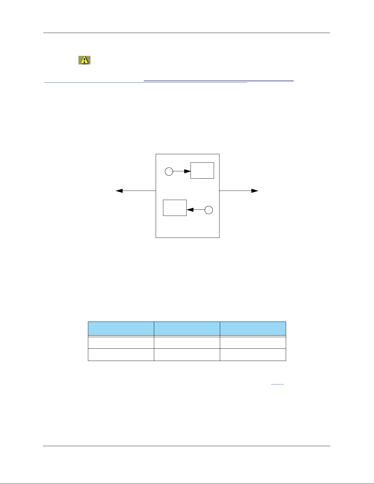
There are two kinds of filters you can add to a filter set: input and output. Input filters check packets
received from the Internet, destined for your network. Output filters check packets transmitted from your
network to the Internet.
packet
WAN
input filter
packet
output filter
The Motorola Netopia® Router
Packets in Netopia Embedded Software Version 7.7.4 pass through an input filter if they originate from the WAN and
through an output filter if they’re being sent out to the WAN.
The process for adding input and output filters is exactly the same. The main difference between the two
involves their reference to source and destination. From the perspective of an input filter, your local network
is the destination of the packets it checks, and the remote network is their source. From the perspective of
an output filter, your local network is the source of the packets, and the remote network is their destination.
Type of filter Source means Destination means
Input filter The remote network The local network
Output filter The local network The remote network
LAN
To add a filter, select the Filter Set Name to which you will add a filter, and click the Edit button.
172
Page 3

The Filter Set page appears.
☛ Note:
There are two Add buttons in this page, one for input filters and one for output filters. In this
section, you’ll learn how to add an input filter to a filter set. Adding an output filter works
exactly the same way, providing you keep the different source and destination perspectives in
mind.
173
Page 4

Administrator’s Handbook
1. To add a filter, click the Add button under Input Rules.
The Input Rule Entry page appears.
2. If you want the filter to forward packets that match its criteria to the destination IP
address, check the
If Forward is unchecked, packets matching the filter’s criteria will be discarded.
3. Enter the
You can enter a subnet or a host address.
4. Enter the
This allows you to further modify the way the filter will match on the source address. Enter 0.0.0.0 to
force the filter to match on all source IP addresses, or enter 255.255.255.255 to match the source IP
address exclusively.
5. Enter the
You can enter a subnet or a host address.
6. Enter the
This allows you to further modify the way the filter will match on the destination address. Enter 0.0.0.0
to force the filter to match on all destination IP addresses.
7. If desired, you can enter a TOS and TOS Mask value.
See “Policy-based Routing using Filtersets” on page 177 for more information.
8. Select
Source IP
Source Mask
Destination IP
Destination Mask
Protocol
Forward
checkbox.
address this filter will match on.
for the source IP address.
Address this filter will match on.
for the destination IP address.
from the pull-down menu: ICMP, TCP, UDP, Any, or the number of
another IP transport protocol (see the table on page 167).
If Protocol Type is set to TCP or UDP, the settings for port comparison will appear. These settings only
take effect if the Protocol Type is TCP or UDP.
9. From the
Source Port Compare
pull-down menu, choose a comparison method for the
filter to use on a packet’s source port number.
Then select
page 166).
10. From the Destination Port Compare pull-down menu, choose a comparison method for
Source Port
and enter the actual source port number to match on (see the table on
the filter to use on a packet’s destination port number.
Then select
on page 166).
Destination Port
and enter the actual destination port number to match on (see the table
174
Page 5

11. When you are finished configuring the filter, click the Submit button to save the filter in
the filter set.
Viewing filters
To display the table of input or output filters, select the Filter Set Name in the Filter Set page and click the
Add or Edit button.
The table of filters in the filtersets appears.
Modifying filters
To modify a filter, select a filter from the table and click the Edit button. The Rule Entry page appears. The
parameters in this page are set in the same way as the ones in the original Rule Entry page (see “Adding fil-
ters to a filter set” on page 172).
Deleting filters
To delete a filter, select a filter from the table and click the Delete button.
Moving filters
To reorganize the filters in a filter set, select a filter from the table and click the Move Up or Move Down
button to place the filter in the desired priority position.
Deleting a filter set
If you delete a filter set, all of the filters it contains are deleted as well. To reuse any of these filters in
another set, before deleting the current filter set you’ll have to note their configuration and then recreate
them.
To delete a filter set, select the filter set from the Filter Sets list and click the Delete button.
175
Page 6
Administrator’s Handbook
Associating a Filter Set with an Interface
Once you have created a filter set, you must associate it with an interface in order for it to be effective.
Depending on its application, you can associate it with either the WAN (usually the Internet) interface or the
LAN.
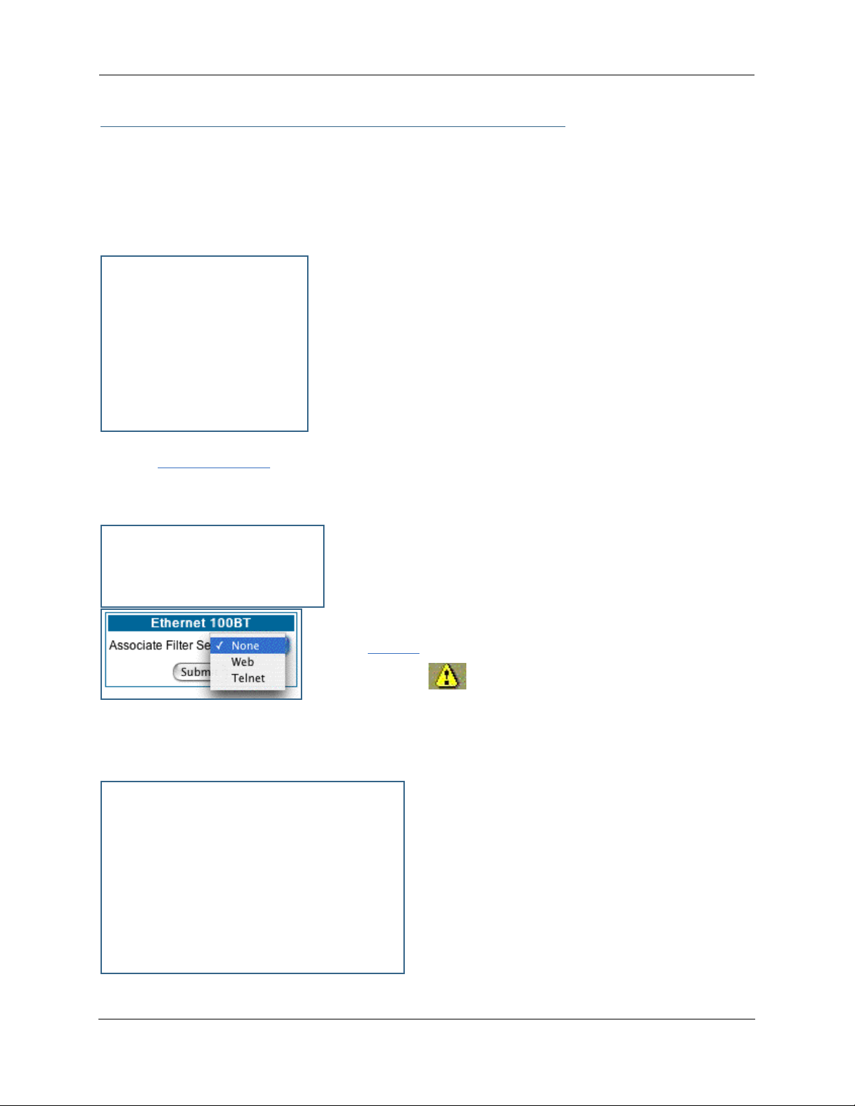
To associate an filter set with the LAN, return to the Filter Sets page.
Click the Ethernet 100BT link.
The Ethernet 100BT page appears.
From the pull-down menu, select the filter set to associate with this
interface.
Click the Submit button. The Alert icon will appear in the upper right
corner of the page.
Click the Alert icon to go to the validation page, where you can save your configuration.
You can repeat this process for both the WAN and LAN interfaces, to associate your filter sets.
When you return to the Filter Sets page, it will display
your interface associations.
176
Page 7
Policy-based Routing using Filtersets
Netopia Embedded Software Version 7.7.4 offers the ability to route IP packets using criteria other than the
destination IP address. This is called policy-based routing.
You specify the routing criteria and routing information by using IP filtersets to determine the forwarding
action of a particular filter.
You specify a gateway IP address, and each packet matching the filter is routed according to that gateway
address, rather than by means of the global routing table.
In addition, the classifier list in a filter includes the TOS field. This allows you to filter on TOS field settings
in the IP packet, if you want.
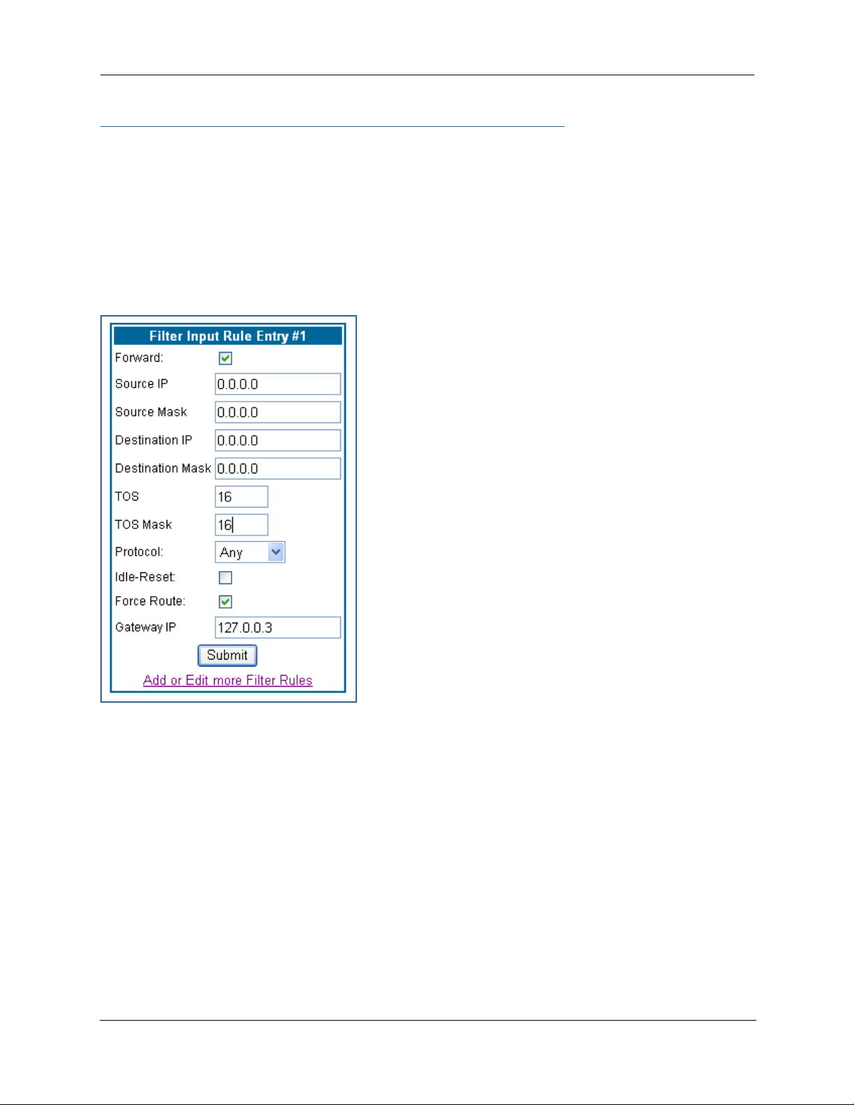
To use the policy-based routing feature, you create a filter that
forwards the traffic.
•Check the Forward checkbox. This will display the Force Rout-
ing options.
•Check the Force Route checkbox.
•Enter the Gateway IP address in standard dotted-quad nota-
tion to which the traffic should be forwarded.
•You can enter Source and Destination IP Address(es) and
Mask(s), Protocol Type, and Source and Destination Port
ID(s) for the filter, if desired.
TOS field matching
Netopia Embedded Software Version 7.7.4 includes two
parameters for an IP filter: TOS and TOS Mask. Both fields
accept values in the range 0 – 255.
Certain types of IP packets, such as voice or multimedia
packets, are sensitive to latency introduced by the network. A
delay-sensitive packet is one that has the low-latency bit set in
the TOS field of the IP header. This means that if such packets
are not received rapidly, the quality of service degrades. If you
expect to route significant amounts of such traffic you can
configure your router to route this type of traffic to a gateway
other than your normal gateway using this feature.
The TOS field matching check is consistent with source and destination address matching.
If you check the Idle Reset checkbox, a match on this rule will keep the WAN connection alive by resetting
the idle-timeout status.
The Idle Reset setting is used to determine if a packet which matches the filter will cause an “instant-on”
link to connect, if it is down; or reset its idle timer, if it is already up. For example, if you wanted ping traffic
not to keep the link up, you would create a filter which forwards a ping, but with the Idle Reset checkbox
unchecked.
177
Page 8
Administrator’s Handbook
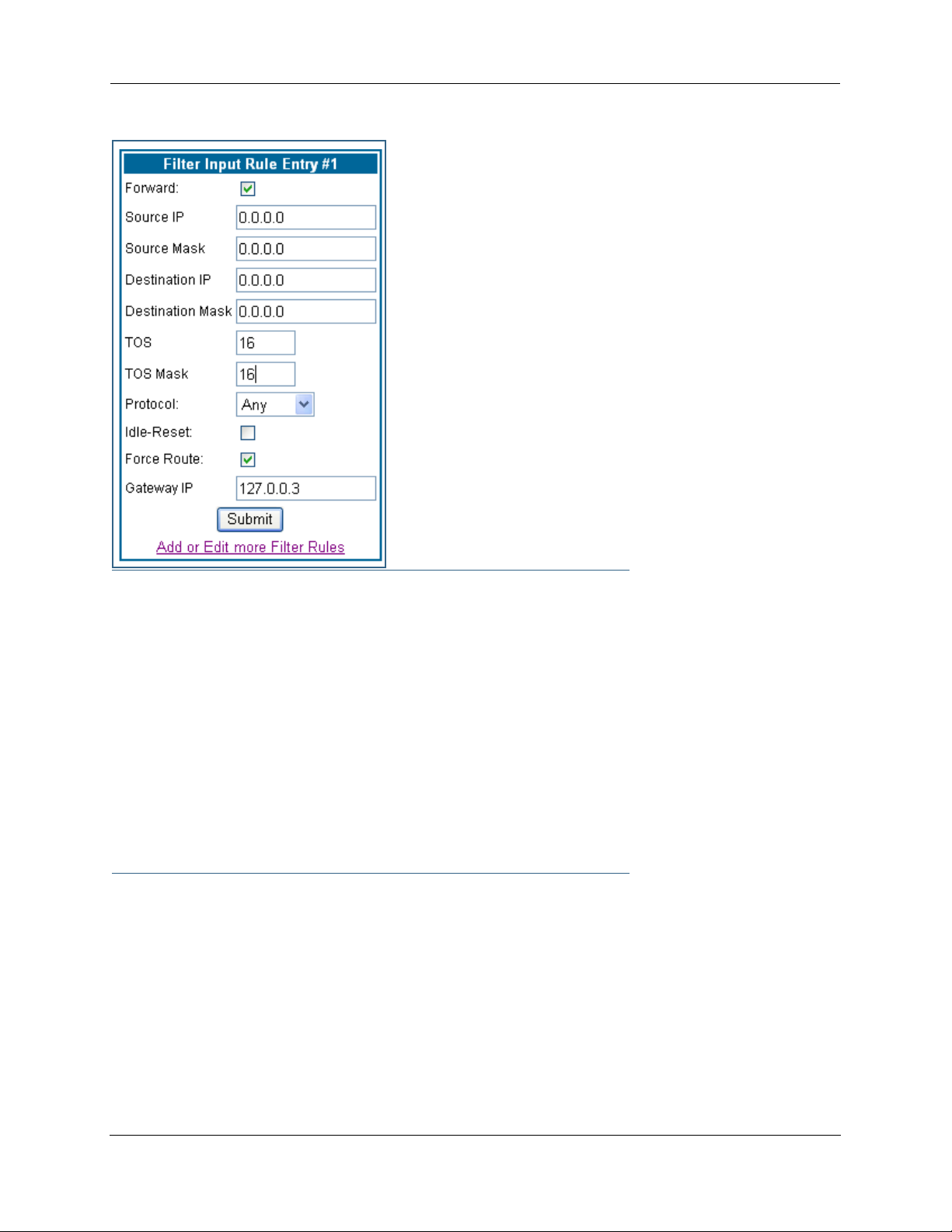
Example: You want packets with the TOS low latency bit to go
through VC 2 (via gateway 127.0.0.3 – the Motorola Netopia®
Gateway will use 127.0.0.x, where x is the WAN port + 1) instead
of your normal gateway.
You would set up the filter as shown here.
☛ NOTE:
Default Forwarding Filter
If you create one or more filters that have a matching action of forward, then action on a
packet matching none of the filters is to block any traffic.
Therefore, if the behavior you want is to force the routing of a cer tain type of packet and pass
all others through the normal routing mechanism, you must configure one filter to match the
first type of packet and apply Force Routing. A subsequent filter is required to match and forward all other packets.
Management IP traffic
If the Force Routing filter is applied to source IP addresses, it may inadver tently block communication with the router itself. You can avoid this by preceding the Force Routing filter with a filter that matches the destination IP address of the Gateway itself.
178
Page 9

Link: Security Log
Security Monitoring is a keyed feature. See page 187 for information concerning installing Motorola Netopia® Software Feature Keys.
Security Monitoring detects security-related events, including common types of malicious attacks, and
writes them to the security log file.
Using the Security Monitoring Log
You can view the Security Log at any time. Use the following steps:
1. Click the Security
2. Click the Security Log link.
3. Click the Show link from the Security Log tool bar.
4. An example of the Security Log is shown on the next page.
5. When a new security event is detected, you will see the Alert button.
toolbar button.
The Security Alert remains until you view the information. Clicking the Alert button will take you directly
to a page showing the log.
179
Page 10

Administrator’s Handbook
Your Netopia Gateway has detected and successfully blocked an event that could have
compromised the security of your network.
Please refer to your customer documentation for a description of the logged event.
Number of security log entries : 5
Security alert type : Port Scan
Protocol type : TCP
IP source address : 143.137.137.14
Time at last attempt : Fri May 21 15:17:40 2004 (UTC)
Number of ports that were scanned : 9
Highest port : 1167
Lowest port : 1094
1102 1108 1094 1099 1166 1167 1151 1160 1164
Security alert type : Excessive Pings
IP source address : 143.137.137.92
IP destination address : 143.137.199.8
Number of attempts : 90
Time at last attempt : Fri May 21 17:52:22 2004 (UTC)
Security alert type : Port Scan
Protocol type : TCP
IP source address : 143.137.50.2
Time at last attempt : Fri May 21 17:51:37 2004 (UTC)
Number of ports that were scanned : 241
Highest port : 5302
Lowest port : 73
111 473 602 863 817 1994 805 395 5302 1670
(Only the first 10 ports are recorded.)
Security alert type : Port Scan
Protocol type : UDP
IP source address : 143.137.50.2
Time at last attempt : Fri May 21 17:52:43 2004 (UTC)
Number of ports that were scanned : 162
Highest port : 5236
Lowest port : 1
583 1 1471 444 4133 811 5236 650 776 1492
(Only the first 10 ports are recorded.)
Security alert type : Illegal Packet Size (Ping of Death)
IP source address : 192.168.1.3
IP destination address : 143.137.199.8
Number of attempts : 5
Time at last attempt : Fri May 21 18:05:33 2004 (UTC)
Illegal packet size : 65740
The capacity of the security log is 100 security alert messages. When the log reaches capacity, subsequent
messages are not captured, but they are noted in the log entr y count.
To reset this log, select
Reset from the Security Monitor tool bar.
The following message is displayed.
The security log has been reset.
180
Page 11

When the Security Log contains no entries, this is the response:
The security log is empty.
Timestamp Background
During bootup, to provide better log information and to suppor t improved troubleshooting, a Motorola Netopia® Gateway acquires the National Institute of Standards and Technology (NIST) Universal Coordinated
Time (UTC) reference signal, and then adjusts it for your local time zone.
Once per hour, the Gateway attempts to re-acquire the NIST reference, for re-synchronization or initial acquisition of the UTC information. Once acquired, all subsequent log entries display this date and time information. UTC provides the equivalent of Greenwich Mean Time (GMT) information.
If the WAN connection is not enabled (or NTP has been disabled), the internal clocking function of the Gateway provides log timestamps based on “uptime” of the unit.
181
Page 12

Administrator’s Handbook
Install
Button: Install
From the Install toolbar button you can Install new Operating System Software and Feature Keys as
updates become available.
On selected models, you can install a Secure Sockets Layer (SSL V3.0) certificate from a trusted Cer tification Authority (CA) for authentication purposes. If this feature is available on your Gateway, the Install Cer-
tificate link will appear in the Install page as shown. Otherwise, it will not appear.
182
Page 13

Link: Install Software
(This link is not available on the 3342/3352 models, since firmware updates must be upgraded via the
USB host driver. 3342N/3352N models are upgradeable by this procedsure.)
This page allows you to install an updated release of the Motorola Netopia® Firmware.
Updating Your Gateway’s Motorola Netopia® Firmware Version. You install a new operat-
ing system image in your unit from the Install Operating System Software page. For this process, the computer you are using to connect to the Motorola Netopia® Gateway must be on the same local area network
as the Motorola Netopia® Gateway.
Step 1: Required Files
Upgrading Netopia Embedded Software Version 7.7.4 requires a Motorola Netopia® firmware image file.
Background
Firmware upgrade image files are posted periodically on the Motorola Netopia® website. You can download
the latest operating system software for your Gateway by accessing the following URL:
http://www.netopia.com/support/hardware/
Be sure to download the correct file for your par ticular Gateway. Different Gateway models have different
firmware files. Also, be sure your ISP suppor ts the version of firmware you want to use.
183
Page 14

Administrator’s Handbook
When you download your firmware upgrade from the Motorola Netopia® website, be sure to download the
latest User Guide PDF files. These are also posted on the Motorola Netopia® website in the Documentation
Center.
Confirm Motorola Netopia® Firmware Image Files
The Motorola Netopia® firmware Image file is specific to the model and the product identification number.
1. Confirm that you have received the appropriate Motorola Netopia® Firmware Image file.
2. Save the Motorola Netopia® Firmware image file to a convenient location on your PC.
Step 2: Motorola Netopia® firmware Image File
Install the Motorola Netopia® firmware Image
To install the Motorola Netopia® firmware in your Motorola Netopia® Gateway from the Home Page use
the following steps:
1. Open a web connection to your Motorola Netopia® Gateway from the computer on your
LAN.
2. Click the Install Software button on the Motorola Netopia® Gateway
The Install Operating System Software window opens.
3. Enter the filename into the text box by using one of these techniques:
The Motorola Netopia® firmware file name begins with a shor tened form of the version number and
ends with the suffix “.bin” (for “binary”). Example: nta760.bin
a. Click the Browse button, select the file you want, and click Open.
-orb. Enter the name and path of the software image you want to install in the text field.
4. Click the Install Software button.
The Motorola Netopia® Gateway copies the image file from your computer and installs it into its memor y
storage. You see a progress bar appear on your screen as the image is copied and installed.
Home
page.
184
Page 15

When the image has been installed, a success message displays.
5. When the success message appears, click the Restart button and confirm the Restart
when you are prompted.
Your Motorola Netopia® Gateway restarts with its new image.
Verify the Motorola Netopia® Firmware Release
To verify that the Motorola Netopia® firmware image has loaded successfully, use the following steps:
1. Open a web connection to your Motorola Netopia® Gateway from the computer on your
LAN and return to the Home page.
185
Page 16

Administrator’s Handbook
2. Verify your Motorola Netopia® firmware release, as shown on the Home Page.
This completes the upgrade process.
186
Page 17

Link: Install Key
You can obtain advanced product functionality by employing a software Feature Key. Software feature keys
are specific to a Gateway's serial number. Once the feature key is installed and the Gateway is restarted,
the new feature's functionality becomes enabled.
Use Motorola Netopia® Software Feature Keys
Motorola Netopia® Gateway users obtain advanced product functionality by installing a software feature
key. This concept utilizes a specially constructed and distributed keycode (referred to as a feature key) to
enable additional capability within the unit.
Software feature key proper ties are specific to a unit’s serial number; they will not be accepted on a platform with another serial number.
Once installed, and the Gateway restarted, the new feature’s functionality becomes available. This allows
full access to configuration, operation, maintenance and administration of the new enhancement.
Obtaining Software Feature Keys
Contact Motorola or your Service Provider to acquire a Software Feature Key.
Procedure - Install a New Feature Key File
With the appropriate feature keycode, use the steps listed below to enable a new function.
1. From the Home page, click the Install toolbar button.
2. Click Install Keys
The Install Key File page appears.
3. Enter the feature keycode in the input Text Box.
Type the full keycode in the Text Box.
187
Page 18

Administrator’s Handbook
4. Click the Install Key button.
5. Click the Restart toolbar button.
The Confirmation screen appears.
188
Page 19

6. Click the Restart the Gateway link to confirm.
To check your installed features:
7. Click the Install toolbar button.
8. Click the list of features link.
The System Status page appears with the information from the features link displayed below. You can
check that the feature you just installed is enabled.
189
Page 20

Administrator’s Handbook
Link: Install Certificate
Secure Sockets Layer (SSL) is a protocol for transmitting private information over the Internet. SSL uses
two keys to encrypt data: a public key known to everyone and a private or secret key known only to the
recipient of the message.
Netopia Embedded Software Version 7.7.4 uses SSL certificates for TR-069 suppor t.
SSL certificates are issued by trusted Cer tification Authorities (CAs). The CA digitally signs each cer tificate.
Each client contains a list of trusted CAs. When an SSL handshake between a ser ver and your Gateway
occurs, the client verifies that the server certificate was issued by a trusted CA. If the CA is not trusted, a
warning will appear. Certificates installed in your Gateway and ser vers to which it connects verify to each
other that communications between them are encrypted and private.
Certificates are purchased from an issuing Cer tificate Authority, usually by your corporate IT department or
other service provider, and provided to users for secure communications.
You must obtain a certificate file before you can install it.
1. To install an SSL certificate, click the Install Certificate link.
190
Page 21

The Install Certificate page appears.
2. Browse to the location where you have saved your certificate and select the file, or type
the full path.
3. Click the Install Certificate button.
4. Restart your Gateway.
191
Page 22

Administrator’s Handbook
192
Page 23

CHAPTER 4 Basic Troubleshooting
This section gives some simple suggestions for troubleshooting problems with your Gateway’s initial configuration.
Before troubleshooting, make sure you have
• read the Quickstart Guide;
• plugged in all the necessar y cables; and
• set your PC’s TCP/IP controls to obtain an IP address automatically.
193
Page 24
Administrator’s Handbook
Status Indicator Lights
The first step in troubleshooting is to check the status indicator lights (LEDs) in the order outlined below.
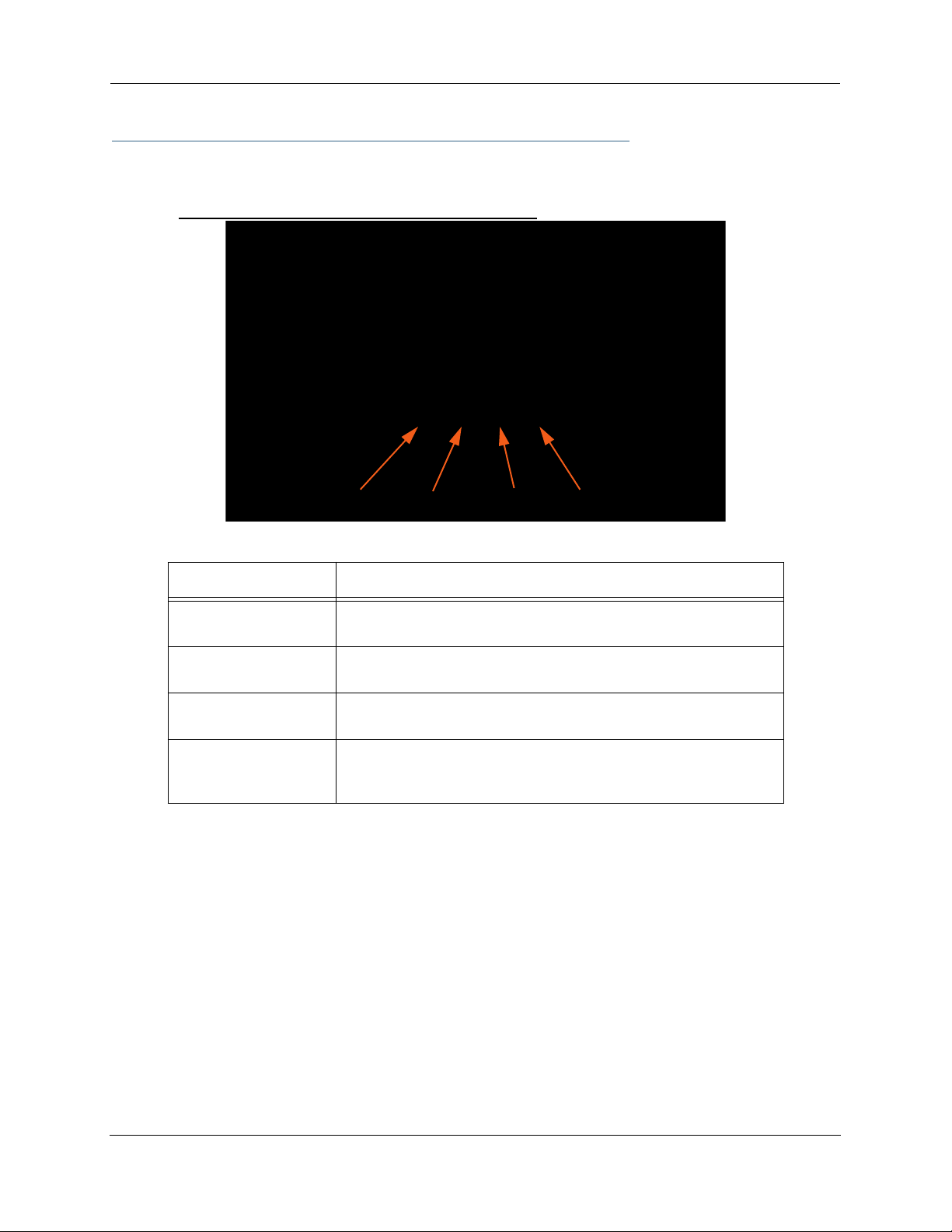
Motorola Netopia® Gateway 2210 status indicator lights
Power Ethernet DSL Internet
LED Action
Power
Ethernet
DSL
Internet
Green when power is on. Red if device malfunctions. Flashes Red
when new embedded software is being installed.
Solid green when connected. Flash green when there is activity on
the LAN.
Solid green when trained. Blinking green when no line is attached or
when training.
Solid green when Broadband device is connected. Flashes green for
activity on the WAN port. If the physical link comes up, but PPP or
DHCP fail, the LED turns red.
194
Page 25
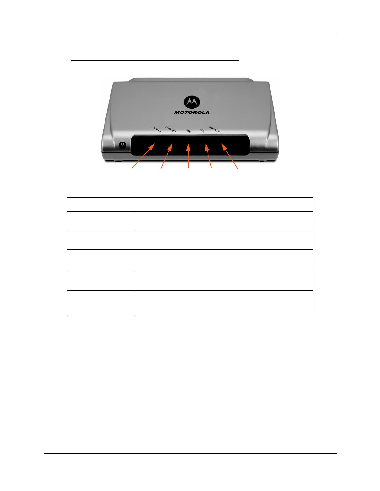
Motorola Netopia® Gateway 2240N/2241N status indicator lights
Power Ethernet DSLUSB Internet
LED Action
Power
Ethernet
USB
(Model 2241N only)
DSL
Internet
Green when power is on. Red if device malfunctions. Flashes Red
when new embedded software is being installed.
Solid green when connected. Flash green when there is activity on
the LAN.
Solid green when connected. Flash green when there is activity on
the LAN.
Solid green when trained. Blinking green when no line is attached or
when training.
Solid green when Broadband device is connected. Flashes green for
activity on the WAN port. If the physical link comes up, but PPP or
DHCP fail, the LED turns red.
195
Page 26
Administrator’s Handbook
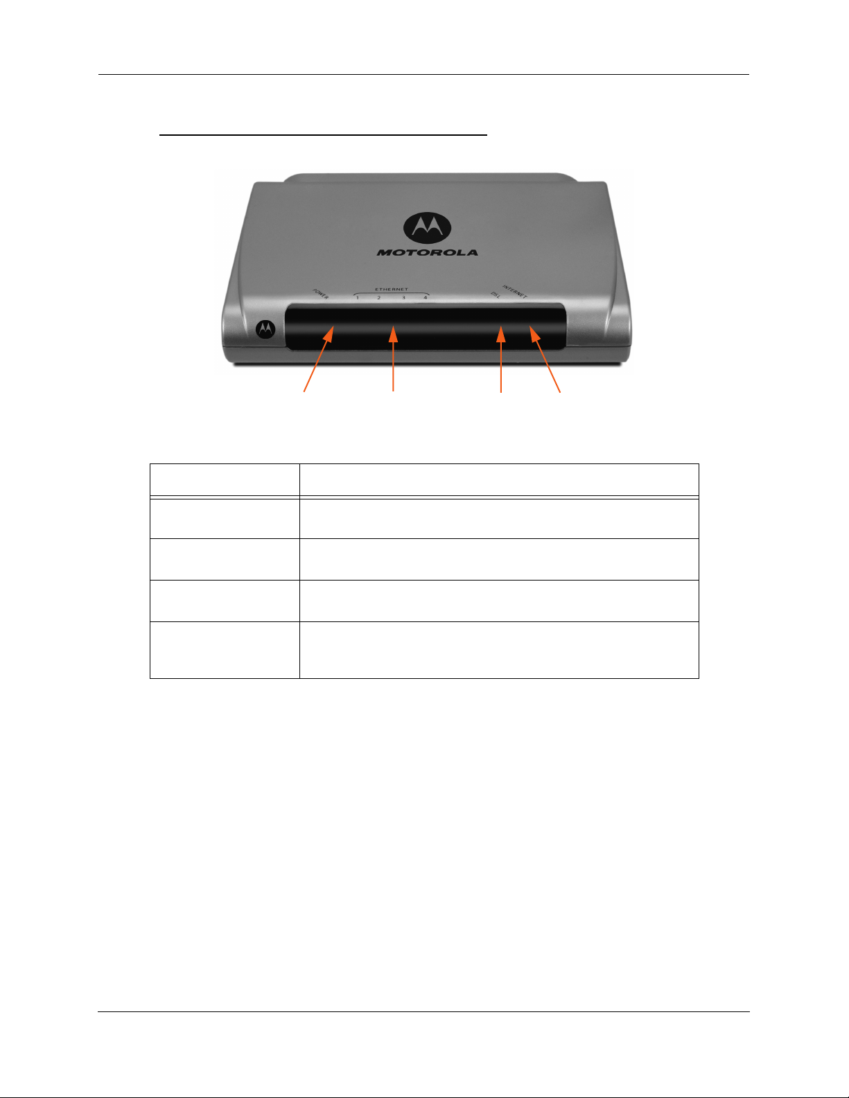
Motorola Netopia® Gateway 2246N status indicator lights
Power Ethernet 1, 2, 3, 4 DSL Internet
LED Action
Power
Ethernet 1, 2, 3, 4
DSL
Internet
Green when power is on. Red if device malfunctions. Flashes Red
when new embedded software is being installed.
Solid green when connected. Flash green when there is activity on
the LAN.
Solid green when trained. Blinking green when no line is attached or
when training.
Solid green when Broadband device is connected. Flashes green for
activity on the WAN port. If the physical link comes up, but PPP or
DHCP fail, the LED turns red.
196
Page 27

Motorola Netopia® Gateway 2247NWG status indicator lights
Power Ethernet 1, 2, 3, 4 DSLWireless Internet
LED Action
Power
Ethernet 1, 2, 3, 4
Wireless
DSL
Internet
Green when power is on. Red if device malfunctions. Flashes Red
when new embedded software is being installed.
Solid green when connected. Flash green when there is activity on
the LAN.
Flashes green when there is activity on the wireless LAN. Of f if driver
fails to initialize, or if wireless is disabled.
Solid green when trained. Blinking green when no line is attached or
when training.
Solid green when Broadband device is connected. Flashes green for
activity on the WAN port. If the physical link comes up, but PPP or
DHCP fail, the LED turns red.
197
Page 28

Administrator’s Handbook
Motorola Netopia® Gateway 3340(N), 3341(N), 3351(N) status indicator lights
LED Action
Ethernet Link
Ethernet Traffic
DSL Traffic
DSL Sync
USB Active
(Model 3341N only)
PPPoE Active
(Model 3340N only)
Power
PowerUSB ActiveDSL Traffic DSL SyncEthernet TrafficEthernet Link
Solid green when connected.
Flashes green when there is activity on the LAN.
Blinks green when traffic is sent/received over the WAN.
Blinking green with no line attached or training, solid green when
trained with the DSL line.
Solid green when connected; otherwise, not lit.
Solid green when PPPoE is negotiated; otherwise, not lit.
Green when power is on. Red if device malfunctions. Flashes Red
when new embedded software is being installed.
198
Page 29

Motorola Netopia® Gateway 3342/3342N, 3352/3352N status indicator lights
USB:
Solid green when USB is connected
otherwise, not lit
DSL:
Blinking green with no line attached or training,
solid green when trained with the DSL line.
☛ Special patterns:
• Both LEDs are off during boot (power on boot or warm reboot).
• When the 3342/3352 successfully boots up, both LEDs flash green once.
• Both LEDs are off when the Host OS suspends the device, (e.g. Windows standby/reboot,
device disabled, driver uninstalled, etc.)
199
Page 30

Administrator’s Handbook
Motorola Netopia® Gateway 3346(N), 3356(N) status indicator lights
LED Action
Power
DSL Sync
LAN 1, 2, 3, 4
Green when power is on. Red if device malfunctions. Flashes Red
when new embedded software is being installed.
Blinking green with no line attached or training, solid green when
trained with the DSL line.
Solid green when connected; Flash green when there is activity on the
LAN.
PowerDSL SyncLAN 1, 2, 3, 4
200
Page 31

Motorola Netopia® Gateway 3347W, 3347(N)WG status indicator lights
LED Action
PowerLAN 1, 2, 3, 4 DSL Sync Wireless Link
Power
DSL Sync
Ethernet 1, 2, 3, 4
Wireless Link
Green when power is on. Red if device malfunctions. Flashes Red
when new embedded software is being installed.
Solid green when trained. Blinking green when no line is attached or
when training. Flashes green for DSL traffic.
Solid green when connected. Flash green when there is activity on
the LAN.
Flashes green when there is activity on the wireless LAN. Of f if driver
fails to initialize, or if wireless is disabled.
201
Page 32

Administrator’s Handbook
Motorola Netopia® Gateway MiAVo status indicator lights
LED Action
Power
DSL
(DSL 1 & 2: ADSL2+
models only)
Ethernet 1, 2, 3, 4
Wireless
DSL
Wireless
Green when power is on. Red if device malfunctions. Flashes Red
when new embedded software is being installed.
Solid green when trained. Blinking green when no line is attached or
when training. Flashes green for DSL traffic.
Solid green when connected. Flash green when there is activity on
the LAN.
Flashes green when there is activity on the wireless LAN. Of f if driver
fails to initialize, or if wireless is disabled.
Ethernet 1, 2, 3, 4
Power
202
Page 33

Motorola Netopia® Gateway 7346/56-series MiAVo status indicator lights
Power DSLEthernet 1, 2, 3, 4
LED Action
Power
Ethernet 1, 2, 3, 4
DSL
Green when power is on. Red if device malfunctions. Flashes Red
when new embedded software is being installed.
Solid green when connected. Flash green when there is activity on
the LAN.
Solid green when trained. Blinking green when no line is attached or
when training. Flashes green for DSL traffic.
203
Page 34

Administrator’s Handbook
LED Function Summary Matrix
Flashing
Green
Activity on the
USB cable
Attempting to
train with DSLAM
DSL cable
Ethernet port
N/A N/A N/A
Activity on the
WAN port.
Activity on the
WLAN.
Solid Red Flashing Red
N/A N/A
N/A N/A
N/A N/A
N/A N/A
Physical link
established, but
PPP or DHCP
fails.
N/A N/A
Power
USB Active
DSL Sync
DSL Traffic
Ethernet
Traffic
Ethernet Link
Internet
Wireless
Unlit Solid Green
No power Power on N/A System failure Installing new
No signal USB port con-
nected to PC
No signal DSL line synched
with the DSLAM
No signal N/A Activity on the
No signal N/A Activity on the
No signal Synched with Ether-
net card
No signal Broadband device
is connected.
Wireless is
disabled.
Wireless is
enabled.
If a status indicator light does not look correct, look for these possible problems:
embedded software
N/A
LED State Possible problems
1. Make sure the power switch is in the ON position.
2. Make sure the power adapter is plugged into the 2200-, 3300- or 7000-series DSL Gate-
Power Unlit
DSL
Sync
Unlit
EN Link Unlit
way properly.
3. Try a known good wall outlet.
4. Replace the power supply and/or unit.
1. Make sure the you are using the correct cable. The DSL cable is the thinner standard tele-
phone cable.
2. Make sure the DSL cable is plugged into the correct wall jack.
3. Make sure the DSL cable is plugged into the DSL port on the 2200-, 3300- or 7000-series
DSL Gateway.
4. Make sure the DSL line has been activated at the central office DSLAM.
5. Make sure the 2200-, 3300- or 7000-series DSL Gateway is not plugged into a micro filter.
Note: EN Link light is inactive if only using USB.
1. Make sure the you are using the Ethernet cable, not the DSL cable. The Ethernet cable is
thicker than the standard telephone cable.
2. Make sure the Ethernet cable is securely plugged into the Ethernet jack on the PC.
3. If plugging a 2200-, 3300- or 7000-series DSL Gateway into a hub the you may need to
plug into an uplink port on the hub, or use an Ethernet cross over cable.
4. Make sure the Ethernet cable is securely plugged into the Ethernet por t on the 2200-,
3300- or 7000-series DSL Gateway.
5. Try another Ethernet cable if you have one available.
204
Page 35

EN Traffic Unlit
USB
Active
DSL
Traffic
Wireless
Link
Unlit
Unlit
Unlit
1. Make sure you have Ethernet drivers installed on the PC.
2. Make sure the PC’s TCP/IP Proper ties for the Ethernet Network Control Panel is set to
obtain an IP address via DHCP.
3. Make sure the PC has obtained an address in the 192.168.1.x range. (You may have
changed the subnet addressing.)
4. Make sure the PC is configured to access the Internet over a LAN.
5. Disable any installed network devices (Ethernet, HomePNA, wireless) that are not being
used to connect to the 2200-, 3300- or 7000-series DSL Gateway.
Note: USB Active light is inactive if only using Ethernet.
1. Make sure you have USB drivers installed on the PC.
2. Make sure the PC’s TCP/IP Proper ties for the USB Network Control Panel is set to obtain
an IP address via DHCP.
3. Make sure the PC has obtained an address in the 192.168.1.x range. (You may have
changed the subnet addressing.)
4. Make sure the PC is configured to access the Internet over a LAN.
5. Disable any installed network devices (Ethernet, HomePNA, wireless) that are not being
used to connect to the 2200-, 3300- or 7000-series DSL Gateway.
Launch a browser and try to browse the Internet. If the DSL Active light still does not flash,
then proceed to Advanced Troubleshooting below.
• Make sure your client PC(s) have their wireless cards correctly installed and configured.
• Check your client PC(s) TCP/IP settings to make sure they are receiving an IP address from
the wireless Router.
• Check the Gateway’s log for wireless driver failure messages.
205
Page 36

Administrator’s Handbook
Factory Reset Switch
(not supported on some models; 3342/3342N/3352/3352N models do not have a reset switch)
Lose your password? This section shows how to reset the Motorola Netopia® Gateway so that you can
access the configuration screens once again.
☛ NOTE: Keep in mind that all of your settings will need to be reconfigured.
If you don't have a password, the only way to access the Motorola Netopia® Gateway is the following:
1. Referring to the following diagram, find the round Reset Switch opening.
MiaVo
DSL
LAN
4
1
2
3
Factory Reset Switch:
Push to clear all settings
3347W/3357W
DSL
3
LAN
4
2
1
Factory Reset Switch:
Push to clear all settings
3341/3351
3
4
Ethernet
USB
2
DSL
1
Power
On / Off
Factory Reset Switch:
Push to clear all settings
3346/3356
3
LAN
4
2
1
DSL
Power
Power
Off/On
2247NWG
ON
OFF
4 3 ETHERNET 2 1
DSL POWER
Power
Off / On
Factory Reset Switch:
Push to clear all settings
RESET
2240N
Factory Reset Switch: Push to clear all settings
2241N
2246N
Off / On
Factory Reset Switch:
Push to clear all settings
Factory Reset Switch:
Push to clear all settings
2. Carefully insert the point of a pen or an unwound paperclip into the opening.
•
If you press the factory default button for less than 1/2 a second, the unit will continue to run as normal.
• If you press the factory default button for 1 second, when you release it, the Gateway will perform a fac-
tory reset, clear all settings and configurations, and reboot. Do not hold the button down too long (5 –
10 seconds). This will destroy any saved default settings as well.
206
Page 37

CHAPTER 5 Advanced Troubleshooting
Advanced Troubleshooting can be accessed from the Gateway’s Web UI. Point your browser to
http://192.168.1.254
appear, then do a release and renew in Windows networking to see what the Gateway address really is.)
. The main page displays the device status. (If this does not make the Web UI
207
Page 38

Administrator’s Handbook
Home Page
The home page displays basic information about the Gateway. This includes the ISP Username, Connection
Status, Device Address, Remote Gateway Address, DNS-1, and DNS-2. If you are not able to connect to the
Internet, verify the following:
Item Description
Local WAN IP Address This is the negotiated address of the Gateway’s WAN interface. This
address is usually dynamically assigned.
Remote Gateway
Address
Status of Connection ‘Waiting for DSL’ is displayed while the Gateway is training. This
ISP Username This should be the valid PPPoE username. If not, go to Expert Mode
Device Address This is the negotiated address of the Gateway’s WAN interface.
This is the negotiated address of the remote router to which this Gateway is connected.
should change to ‘Up’ within two minutes. If not, make sure an RJ-11
cable is used, the Gateway is connected to the correct wall jack, and
the Gateway is not plugged into a micro filter.
‘No Connection’ is displayed if the Gateway has trained but failed the
PPPoE login. This usually means an invalid user name or password.
Go to Expert Mode and change the PPPoE name and password.
‘Up’ is displayed when the ADSL line is synched and the PPPoE (or
other connection method) session is established.
‘Down’ is displayed if the line connection fails.
and change to the correct username.
This address is often dynamically assigned. Make sure this is a valid
address.
If this is not the correct assigned address, go to Exper t Mode and verify the PPPoE address has not been manually assigned.
208
Page 39

Item Description
Device Gateway This is the negotiated address of the remote router. Make sure this is
a valid address.
If this is not the correct address, go to Exper t Mode and verify the
address has not been manually assigned.
Primary DNS/
Secondary DNS
Serial Number This is the unique serial number of your Gateway.
Ethernet Status (if so equipped; not available on 3342/3342N/3352/3352N) This is
USB Status This is the status of your USB connection (if equipped). If you are con-
Software Release This is the version number of the current embedded software in your
Warranty Date This is the date that your Gateway was installed and enabled.
Date & Time If this is blank, you likely lack a network connection, or your NTP
NOTE: The Home Page may also display Wireless, VoIP or Backup status depending on
model and configuration. See
on page 133 for more information.
If all of the above seem correct, then access Exper t Mode by clicking the
Expert Mode
link.
These are the negotiated DNS addresses. Make sure they are valid
DNS addresses. (Secondary DNS is optional, and may validly be blank
(0.0.0.0).)
If these are not the correct addresses, go to Expert Mode and verify
the addresses have not been manually assigned.
the status of your Ethernet connection. If you are connecting via Ethernet, it should be Up.
necting via USB, it should be Up.
Gateway.
server information is incorrect.
“Wireless” on page 53, “VoIP” on page 120, or “Backup”
209
Page 40

Administrator’s Handbook
Button: Troubleshoot
Expert Mode
Expert Mode has advanced troubleshooting tools that are used to pinpoint the exact source of a problem.
Clicking the Troubleshoot tab displays a page with links to System Status, Network Tools, and Diagnostics.
• System Status: Displays an overall view of the system and its condition.
• Network Tools: Includes NSLookup, Ping and TraceRoute.
• Diagnostics: Runs a multi-layer diagnostic test that checks the LAN, WAN, PPPoE, and other connection
issues.
210
Page 41

Link: System Status
In the system status screen, there are several utilities that are useful for troubleshooting.
Some examples are given in the following pages.
211
Page 42

Administrator’s Handbook
Link: Ports: Ethernet
The Ethernet port selection shows the traffic sent and received on the Ethernet inter face. There should be
frames and bytes on both the upstream and downstream sides. If there are not, this could indicate a bad
Ethernet cable or no Ethernet connection. Below is an example:
Ethernet Driver Statistics - 10/100 Ethernet
Type: 100BASET
Port Status: Link up
General:
Transmit OK : 7862
Receive OK : 4454
Tx Errors : 0
Rx Errors : 0
Rx CRC Errors : 0
Rx Frame Errors : 0
Upper Layers:
Rx No Handler : 0
Rx No Message : 0
Rx Octets : 975576
Rx Unicast Pkts : 4156
Rx Multicast Pkts : 203
Tx Discards : 0
Tx Octets : 2117992
Tx Unicast Pkts : 3789
Tx Multicast Pkts : 4073
Ethernet driver statistics - USB
Port Status: Link down
General:
Transmit OK : 0
Receive OK : 0
Tx Errors : 0
Rx Errors : 0
Tx Octets : 0
Rx Octets : 0
Ethernet driver statistics - 10/100 Ethernet
Type: 100BASET
Port Status: Link up
General:
Transmit OK : 7863
Receive OK : 4458
Tx Errors : 0
Rx Errors : 0
Rx CRC Errors : 0
Rx Frame Errors : 0
Upper Layers:
Rx No Handler : 0
Rx No Message : 0
Rx Octets : 976327
Rx Unicast Pkts : 4159
Rx Multicast Pkts : 204
Tx Discards : 0
212
Page 43

Link: Ports: DSL
The DSL port selection shows the state of the DSL line, whether it is up or down and how many times the
Gateway attempted to train. The state should indicate ‘up’ for a working configuration. If it is not, check the
DSL cable and make sure it is plugged in correctly and not connected to a micro filter. Below is an example:
ADSL Line State: Up
ADSL Startup Attempts: 5
ADSL Modulation: DMT
Datapump Version: 3.22
Downstream Upstream
---------- --------- SNR Margin: 18.6 14.0 dB
Line Attenuation: 0.4 4.0 dB
Errored Seconds: 14 3
Loss of Signal: 4 4
Loss of Frame: 0 0
CRC Errors: 0 0
Data Rate: 8000 800
213
Page 44

Administrator’s Handbook
Link: IP: Interfaces
The IP interfaces selection shows the state and configuration information for your IP LAN and WAN interfaces. Below is an example:
IP interfaces:
Ethernet 100BT: ( up broadcast default rip-send v1 rip-receive v1 )
inet 192.168.1.1 netmask 255.255.255.0 broadcast 192.168.1.255
physical address 00-16-cb-39-a9-78 mtu 1500
PPP over Ethernet vcc1: ( up address-mapping broadcast default admin-disabled
rip-send v1 rip-receive v1 )
inet 10.1.2.34 netmask 255.255.255.0 broadcast 10.1.2.1
physical address 00-15-bc-28-b8-67 mtu 1500
214
Page 45

Link: DSL: Circuit Configuration
The DSL Circuit Configuration screen shows the traffic sent and received over the DSL line as well as the
trained rate (upstream and downstream) and the VPI/VCI. Verify traffic is being sent over the DSL line. If
not, check the cabling and make sure the Gateway is not connected to a micro filter. Also verify the correct
PVC is listed, which should be 0/35 (some providers use other values, such as 8/35. Check with your provider). If not go to the WAN setup and change the VPI/VCI to its correct value. Below is an example:
ATM port status : Up
Rx data rate (bps) : 8000
Tx data rate (bps) : 800
ATM Virtual Circuits:
VCC # Type VPI VCI Encapsulation
---- ---- --- ----- ------------------------- 1 PVC 8 35 PPP over Ethernet (LLC/SNAP encapsulation)
ATM Circuit Statistics:
Rx Frames : 17092 Tx Frames : 25078
Rx Octets : 905876 Tx Octets : 1329134
Rx Errors : 0 Tx Errors : 0
Rx Discards : 0 Tx Discards : 0
No Rx Buffers : 0 Tx Queue Full : 0
215
Page 46

Administrator’s Handbook
Link: System Log: Entire
The system log shows the state of the WAN connection as well as the PPPoE session. Verify that the
PPPoE session has been correctly established and there are no failures. If there are error messages, go
to the WAN configuration and verify the settings. The following is an example of a successful connection:
Message Log:
Mon Apr 16 10:48:22 2007 L3 KS: Using configured options found in flash
Mon Apr 16 10:48:22 2007 L3 BOOT: Warm start v7.3r0 ---------------------------------Mon Apr 16 10:48:22 2007 L3 IP address server initialization complete
Mon Apr 16 10:48:22 2007 L4 BR: Using saved configuration options
Mon Apr 16 10:48:22 2007 L4 BR: Netopia SOC OS version 7.3.0 (build r0)
Mon Apr 16 10:48:22 2007 L4 BR: Netopia-3000/9495032 (Netopia-3000, rev 1), PID 1205
Mon Apr 16 10:48:22 2007 L4 BR: last install status: Firmware installed successfully
Mon Apr 16 10:48:22 2007 L4 BR: memory sizes - 2048K Flash, 8192K RAM
Mon Apr 16 10:48:22 2007 L3 BR: Starting kernel
Mon Apr 16 10:48:22 2007 L3 AAL5: initializing service
Mon Apr 16 10:48:22 2007 L4 ATM: Waiting for PHY layer to come up
Mon Apr 16 10:48:22 2007 L3 POE: Initializing PPP over Ethernet service
Mon Apr 16 10:48:22 2007 L4 POE: Binding to Ethernet (ether/vcc1)
Mon Apr 16 10:48:22 2007 L3 BRDG: Configuring port (10/100BT-LAN)
Mon Apr 16 10:48:22 2007 L3 BRDG: Bridge not enabled for WAN.
Mon Apr 16 10:48:22 2007 L3 BRDG: Bridging from one WAN port to another is disabled
Mon Apr 16 10:48:22 2007 L3 BRDG: Initialization complete
Mon Apr 16 10:48:22 2007 L4 IP: Routing between WAN ports is disabled
Mon Apr 16 10:48:22 2007 L4 IP: IPSec client pass through is enabled
Mon Apr 16 10:48:22 2007 L4 IP: Address mapping enabled on interface PPP over Ethernet vcc1
Mon Apr 16 10:48:22 2007 L3 IP: Adding default gateway over PPP over Ethernet vcc1
Mon Apr 16 10:48:22 2007 L3 IP: Initialization complete
Mon Apr 16 10:48:22 2007 L3 IPSec: initializing service
Mon Apr 16 10:48:22 2007 L3 IPSec: No feature key available - service disabled
Mon Apr 16 10:48:22 2007 L3 PPP: PPP over Ethernet vcc1 binding to PPPoE
Mon Apr 16 10:48:22 2007 L3 PPP: PPP over Ethernet vcc1 Port listening for incoming PPP connection requests
.
.
Mon Apr 16 10:48:22 2007 L4 RFC1483-1 up
Mon Apr 16 10:48:22 2007 L3 Service-Name=ANY
Mon Apr 16 10:48:22 2007 L3 Host-Uniq 00000001
Mon Apr 16 10:48:22 2007 L3 AC-Name=62011050058192-SMS1800
Mon Apr 16 10:48:22 2007 L3 Service-Name=ANY
Mon Apr 16 10:48:22 2007 L3 lcp: LCP Send Config-Request+
Mon Apr 16 10:48:22 2007 L3 MAGIC 0x2dee0000+
Mon Apr 16 10:48:22 2007 L3 lcp: LCP Recv Config-Req:+
Mon Apr 16 10:48:22 2007 L3 MRU(1492) (ACK) AUTHTYPE(c223) (CHAP) (ACK) MAGICNUMBER
Mon Apr 16 10:48:22 2007 L3 (4403604) (ACK)
Mon Apr 16 10:48:22 2007 L3 lcp: returning Configure-Ack
Mon Apr 16 10:48:22 2007 L3 chap: received challenge, id 1
Mon Apr 16 10:48:22 2007 L3 chap: received success, id 1
Mon Apr 16 10:48:22 2007 L3 ipcp: IPCP Config-Request+
Mon Apr 16 10:48:22 2007 L3 ADDR(0x0) DNS(0x0) DNS2(0x0) WINS(0x0) WINS2(0x0)
Mon Apr 16 10:48:22 2007 L3 ipcp: IPCP Recv Config-Req:+
Mon Apr 16 10:48:22 2007 L3 ADDR(143.137.199.254) (ACK)
Mon Apr 16 10:48:22 2007 L3 ipcp: returning Configure-ACK
Mon Apr 16 10:48:22 2007 L3 ipcp: IPCP Config-Request+
Mon Apr 16 10:48:22 2007 L3 ADDR(0x0) DNS(0x0) DNS2(0x0)
Mon Apr 16 10:48:22 2007 L3 ipcp: IPCP Config-Request+
Mon Apr 16 10:48:22 2007 L3 ADDR(0x8f89c702) DNS(0x8f89320a) DNS2(0x8f898909)
Mon Apr 16 10:48:22 2007 L3 ipcp: negotiated remote IP address 143.137.199.254
Mon Apr 16 10:48:22 2007 L3 ipcp: negotiated IP address 143.137.199.2
Mon Apr 16 10:48:22 2007 L3 ipcp: negotiated TCP hdr compression off
Mon Apr 16 10:48:22 2007 L3 NTP: Update system date & time
Mon Apr 16 10:50:02 L4 TS: "admin" logging in on serial port 0
Mon Apr 16 10:50:02 L4 TS: "Admin" completed login: Full Read/Write access
Mon Apr 16 10:50:02 L4 TS: "Admin" completed login: Full Read/Write access
216
Page 47

Link: Diagnostics
The diagnostics section tests a number of different things at the same time, including the DSL line, the
Ethernet inter face and the PPPoE session.
==== Checking LAN Interfaces
Check Ethernet LAN connect : PASS
Check IP connect to Ethernet (LAN) : PASS
Pinging Gateway : PASS
Check MAC-Bridge connect to Ethernet (LAN) : PASS
==== Checking DSL (WAN) Interfaces
Check DSL Synchronization : PASS
Check ATM Cell-Delineation : PASS
ATM OAM Segment Ping through (vcc1) : WARNING
*** Don't worry, your service provider may not support this test
ATM OAM End-To-End Ping through (vcc1) : WARNING
*** Don't worry, your service provider may not support this test
Check Ethernet connect to AAL5 (vcc1) : PASS
Check PPPOE connect to Ethernet (vcc1) : PASS
Check PPP connect to PPPOE (vcc1) : PASS
Check IP connect to PPP (vcc1) : PASS
Pinging Gateway : PASS
==== Checking Miscellaneous
Check DNS- Query for netopia.com : SKIPPED
Ping DNS Server Primary IP Address : SKIPPED
TEST DONE
The following table summarizes the possible results.
CODE Description
PASS The test was successful.
FAIL The test was unsuccessful.
SKIPPED The test was skipped because a test on which it depended failed, or it was not sup-
ported by the service provider equipment to which it is connected, or it does not
apply.
PENDING The test timed out without producing a result. Try running the test again.
WARNING The test was unsuccessful. The Ser vice Provider equipment your Gateway connects to
may not support this test.
217
Page 48

Administrator’s Handbook
Link: Network Tools
Three test tools are available from this page.
• NSLookup - conver ts a domain name to its IP address and vice versa.
• Ping - tests the “reachability” of a particular network destination by sending an ICMP echo request and
waiting for a reply.
• TraceRoute - displays the path to a destination by showing the number of hops and the router
addresses of these hops.
1. To use the NSLookup capability, type an address (domain name or IP address) in the
text box and click the
Example: Show the IP Address for grosso.com.
Result: The DNS Server doing the lookup is displayed in the Server: and Address: fields. If the Name
Server can find your entry in its table, it is displayed in the Name: and Address: fields.
PING: The network tools section sends a PING from the Gateway to either the LAN or WAN to verify connectivity. A PING could be either an IP address (163.176.4.32) or Domain Name (www.netopia.com).
2. To use the Ping capability, type a destination address (domain name or IP address) in
the text box and click the
Example: Ping to grosso.com.
NSLookup
Server : controller2.netopia.com
Address : 143.137.137.9
Name : www.grosso.com
Address : 192.150.14.120
Ping
button
button.
218
Page 49

ping www.grosso.com
Pinging 192.150.14.120 from local address 143.137.199.8 (timer gran. 100 ms)...
Ping size: 100 Ping count: 5
ICMP echo reply from 192.150.14.120, 200 ms
ICMP echo reply from 192.150.14.120, 100 ms
No ping response.
ICMP echo reply from 192.150.14.120, 100 ms
ICMP echo reply from 192.150.14.120, 100 ms
--- 192.150.14.120 ping statistics --5 packets transmitted, 4 packets received, 20% packet loss
Result: The host was reachable with four out of five packets sent.
219
Page 50

Administrator’s Handbook
Below are some specific tests:
Action
If PING is not successful, possible causes are:
From the Gateway's Network
Tools page:
Ping the internet default gateway IP
address
Ping an internet site by IP address Gateway’s default gateway is incorrect, Gateway’s sub-
Ping an internet site by name DNS is not properly configured on the Gateway; config-
DSL is down, DSL or ATM settings are incorrect; Gateway’s IP address or subnet mask are wrong; gateway
router is down.
net mask is incorrect, site is down.
ured DNS servers are down; site is down.
From a LAN PC:
Ping the Gateway’s LAN IP address IP address and subnet mask of PC are not on the same
scheme as the Gateway; cabling or other connectivity
issue.
Ping the Gateway’s WAN IP address Default gateway on PC is incorrect.
Ping the Gateway’s internet default
gateway IP address
Ping an internet site by IP address PC's subnet mask may be incorrect, site is down.
Ping an internet site by name DNS is not properly configured on the PC, configured
3. To use the TraceRoute capability, type a destination address (domain name or IP
address) in the text box and click the
NAT is off on the Gateway and the internal IP addresses
are private.
DNS servers are down, site is down.
TraceRoute
button.
220
Page 51

Example: Show the path to the grosso.com site.
traceroute www.grosso.com
Traceroute to 192.150.14.120 from address 143.137.199.8 (timer gran. 100 ms)...
30 hops max, 56 byte packets
1 143.137.199.254 100 ms 100 ms 0 ms
2 143.137.50.254 100 ms 0 ms 0 ms
3 143.137.137.254 100 ms 0 ms 100 ms
4 141.154.96.161 0 ms 0 ms 100 ms
5 141.154.8.13 0 ms 100 ms 0 ms
6 4.24.92.97 0 ms 100 ms 0 ms
7 4.24.4.225 100 ms 0 ms 100 ms
8 4.24.7.121 0 ms 0 ms 100 ms
9 4.24.7.113 0 ms 100 ms 0 ms
10 4.24.6.50 100 ms 0 ms 100 ms
11 4.24.10.86 0 ms 100 ms 100 ms
12 4.24.6.234 0 ms 100 ms 0 ms
13 192.205.32.153 100 ms 0 ms 100 ms
14 12.123.1.122 100 ms 0 ms 100 ms
15 12.122.2.173 100 ms 100 ms 100 ms
16 12.122.2.153 100 ms 100 ms 100 ms
17 12.122.5.149 100 ms 200 ms 100 ms
18 12.123.12.189 100 ms 100 ms 200 ms
19 12.124.32.34 100 ms 100 ms 200 ms
20 192.150.14.120 100 ms ! 100 ms ! 100 ms !
Result: It took 20 hops to get to the grosso.com web site.
221
Page 52

Administrator’s Handbook
222
Page 53

CHAPTER 6 Command Line Interface
The Motorola Netopia® Gateway operating software includes a command line inter face (CLI) that lets you
access your Motorola Netopia® Gateway over a telnet connection. You can use the command line interface
to enter and update the unit’s configuration settings, monitor its performance, and restar t it.
This chapter covers the following topics:
• “Overview” on page 224
• “Starting and Ending a CLI Session” on page 226
• “Using the CLI Help Facility” on page 226
• “About SHELL Commands” on page 227
• “SHELL Commands” on page 228
• “About CONFIG Commands” on page 240
• “CONFIG Commands” on page 243
CONFIG Commands
“Remote ATA Configuration Commands” on page 243 “PPPoE with IPoE Settings” on page 282
“DSL Commands” on page 245 “Ethernet Por t Settings” on page 283
“Bridging Settings” on page 246 “802.3ah Ethernet OAM Settings” on page 284
“DHCP Settings” on page 248 “Command Line Interface Preference Settings” on
page 285
“DMT Settings” on page 254 “Port Renumbering Settings” on page 286
“Domain Name System Settings” on page 255 “Security Settings” on page 287
“IGMP Settings” on page 257 “System Settings” on page 298
“IP Settings” on page 259 “Syslog” on page 301
“Queue Configuration” on page 271 “Wireless Settings (suppor ted models)” on page 303
“IPMaps Settings” on page 277 “VLAN Settings” on page 311
“Network Address Translation (NAT) Default Settings” on
page 278
“Network Address Translation (NAT) Pinhole Settings” on
page 278
“PPPoE /PPPoA Settings” on page 279 “DSL Forum settings” on page 321
“SNMP Settings” on page 297 “Backup IP Gateway Settings” on page 323
“VoIP settings” on page 316
“UPnP settings” on page 321
223
Page 54

Administrator’s Handbook
Overview
The CLI has two major command modes: SHELL and CONFIG. Summary tables that list the commands
are provided below. Details of the entire command set follow in this section.
SHELL Commands
Command Status and/or Description
arp to send ARP request
atmping to send ATM OAM loopback
clear to erase all stored configuration information
clear_certificate to remove an SSL certificate that has been installed
clear_log to erase all stored log info in flash memory
configure to configure unit's options
diagnose to run self-test
download to download config file
etheroam to show Ethernet OAM info
exit to quit this shell
help to get more: “help all” or “help help”
install to download and program an image into flash
license to enter an upgrade key to add a feature
log to add a message to the diagnostic log
loglevel to report or change diagnostic log level
netstat to show IP information
nslookup to send DNS query for host
ping to send ICMP Echo request
quit to quit this shell
reset to reset subsystems
restart to restart unit
show to show system information
start to start subsystem
status to show basic status of unit
telnet to telnet to a remote host
traceroute to send traceroute probes
upload to upload config file
view to show configuration information
voip to show VoIP info
who to show who is using the shell
224
Page 55

CONFIG Commands
Command Verbs Status and/or Description
delete Delete configuration list data
help Help command option
save Save configuration data
script Print configuration data
set Set configuration data
validate Validate configuration settings
view View configuration data
Keywords
ata ATA remote config options
atm ATM options (DSL only)
backup Backup gateway options
bridge Bridge options
dhcp Dynamic Host Configuration Protocol options
dmt DMT ADSL options
diffserv Differentiated Services options
dns Domain Name System options
dslf-cpewan TR-069 CPE WAN management
dslf-lanmgnt TR-064 LAN management
dynamic-dns Dynamic DNS client options
ethernet Ethernet options
ethernet-MAC-override Ethernet options
igmp IGMP configuration options
ip TCP/IP protocol options
ip-maps IPmaps options
nat-default Network Address Translation default options
pinhole Pinhole options
ppp Peer-to-Peer Protocol options
wan-over-ether PPP over Ethernet options
preferences Shell environment settings
queue bandwidth queueing options
radius RADIUS Server options
security Security options
servers Internal Server options
snmp SNMP management options
system Gateway’s system options
upnp UPnP options
vdsl VDSL tuning options
vlan VLAN options
wireless Wireless LAN options
Command Utilities
top Go to top level of configuration mode
quit Exit from configuration mode; return to shell mode
exit Exit from configuration mode; return to shell mode
225
Page 56

Administrator’s Handbook
Starting and Ending a CLI Session
Open a telnet connection from a workstation on your network.
You initiate a telnet connection by issuing the following command from an IP host that supports telnet, for
example, a personal computer running a telnet application such as NCSA Telnet.
telnet <ip_address>
You must know the IP address of the Motorola Netopia® Gateway before you can make a telnet connection
to it. By default, your Motorola Netopia® Gateway uses 192.168.1.254 as the IP address for its LAN interface. You can use a Web browser to configure the Motorola Netopia® Gateway IP address.
Logging In
The command line interface log-in process emulates the log-in process for a UNIX host. To logon, enter the
username (either admin or user), and your password.
• Entering the administrator password lets you display and update all Motorola Netopia® Gateway set-
tings.
• Entering a user password lets you display (but not update) Motorola Netopia® Gateway settings.
When you have logged in successfully, the command line interface lists the username and the security level
associated with the password you entered in the diagnostic log.
Ending a CLI Session
You end a command line interface session by typing quit from the SHELL node of the command line interface hierarchy.
Saving Settings
In CONFIG mode, the save command saves the working copy of the settings to the Gateway. The Gateway
automatically validates its settings when you save and displays a warning message if the configuration is
not correct.
Using the CLI Help Facility
The help command lets you display on-line help for SHELL and CONFIG commands. To display a list of the
commands available to you from your current location within the command line inter face hierarchy, enter
help.
To obtain help for a specific CLI command, type help <command>. You can truncate the
to h or a question mark when you request help for a CLI command.
help
command
226
Page 57

About SHELL Commands
You begin in SHELL mode when you start a CLI session. SHELL mode lets you perform the following tasks
with your Motorola Netopia® Gateway:
• Monitor its performance
• Display and reset Gateway statistics
• Issue administrative commands to restart Motorola Netopia® Gateway functions
SHELL Prompt
When you are in SHELL mode, the CLI prompt is the name of the Motorola Netopia® Gateway followed by a
right angle bracket (>). For example, if you open a CLI connection to the Motorola Netopia® Gateway named
“Netopia-3000/9437188,” you would see
SHELL Command Shortcuts
You can truncate most commands in the CLI to their shortest unique string. For example, you can use the
truncated command q in place of the full
rese
for the
reset
command, since the first characters of
Netopia-3000/9437188>
quit
command to exit the CLI. However, you would need to enter
reset
as your CLI prompt.
are common to the
restart
command.
The only commands you cannot truncate are
munications, you must enter the
You can use the Up and Down arrow keys to scroll backward and for ward through recent commands you
have entered. Alternatively, you can use the !! command to repeat the last command you entered.
restart
and
restart
clear
and
clear
. To prevent accidental interruption of com-
commands in their entirety.
227
Page 58

Administrator’s Handbook
SHELL Commands
Common Commands
arp
nnn.nnn.nnn.nnn
Sends an Address Resolution Protocol (ARP) request to match the
Ethernet hardware address.
nnn.nnn.nnn.nnn
IP address to an
clear [yes]
Clears the configuration settings in a Motorola Netopia® Gateway. If you do not use the optional yes qualifier, you are prompted to confirm the clear command.
clear_certificate
Removes an SSL certificate that has been installed.
clear_log
Erases the log information stored in flash if persistent logging is enabled.
configure
Puts the command line interface into Configure mode, which lets you configure your Motorola Netopia®
Gateway with Config commands. Config commands are described starting on page 225.
diagnose
Runs a diagnostic utility to conduct a series of internal checks and loopback tests to verify network connectivity over each interface on your Motorola Netopia® Gateway. The console displays the results of each test
as the diagnostic utility runs. If one test is dependent on another, the diagnostic utility indents its entry in
the console window. For example, the diagnostic utility indents the Check IP connect to Ethernet (LAN)
entry, since that test will not run if the Check Ethernet LAN Connect test fails.
Each test generates one of the following result codes:
CODE Description
PASS The test was successful.
FAIL The test was unsuccessful.
SKIPPED The test was skipped because a test on which it depended failed, or
because the test did not apply to your particular setup or model.
PENDING The test timed out without producing a result. Try running the test again.
download [
This command installs a file of configuration parameters into the Motorola Netopia® Gateway from a TFTP
(Trivial File Transfer Protocol) server. The TFTP server must be accessible on your Ethernet network.
228
server_address
] [
filename
] [confirm]
Page 59

You can include one or more of the following arguments with the download command. If you omit arguments, the console prompts you for this information.
• The
• The
server_address
copy the Motorola Netopia® Gateway configuration file.
filename
argument identifies the path and name of the configuration file on the TFTP ser ver.
argument identifies the IP address of the TFTP ser ver from which you want to
• If you include the optional confirm keyword, the download begins as soon as all information is entered.
You can also download an SSL certificate file from a trusted Cer tification Authority (CA), on platforms that
support SSL, as follows:
download [-cert] [
install [
(Not supported on model 3342/3352)
Downloads a new version of the Motorola Netopia® Gateway operating software from a TFTP (Trivial File
Transfer Protocol) server, validates the software image, and programs the image into the Motorola Netopia® Gateway memory. After you install new operating software, you must restart the Motorola Netopia®
Gateway.
The
pia® Gateway operating software is stored. The
operating software file on the TFTP server.
server_address
server_address
server_address
] [
filename
argument identifies the IP address of the TFTP ser ver on which your Motorola Neto-
] [
filename
] [confirm]
filename
] [confirm]
argument identifies the path and name of the
If you include the optional keyword
to perform the operation.
confirm
, you will not be prompted to confirm whether or not you want
license [key]
This command installs a software upgrade key. An upgrade key is a purchased item, based on the serial
number of the gateway.
log
message_string
Adds the message in the
loglevel [
Displays or modifies the types of log messages you want the Motorola Netopia® Gateway to record. If you
enter the loglevel command without the optional
plays the current log level setting.
You can enter the loglevel command with the
sages you want to record. All messages with a level number equal to or greater than the level you specify
are recorded. For example, if you specify loglevel 3, the diagnostic log will retain high-level informational
messages (level 3), warnings (level 4), and failure messages (level 5).
Use the following values for the
level
]
message_string
level
argument:
argument to the Motorola Netopia® Gateway diagnostic log.
level
argument, the command line inter face dis-
level
argument to specify the types of diagnostic mes-
229
Page 60

Administrator’s Handbook
• 1 or low – Low-level informational messages or greater; includes trivial status messages.
• 2 or medium – Medium-level informational messages or greater; includes status messages that can
help monitor network traffic.
• 3 or high – High-level informational messages or greater; includes status messages that may be signif-
icant but do not constitute errors.
• 4 or warning – Warnings or greater; includes recoverable error conditions and useful operator infor-
mation.
• 5 or failure – Failures; includes messages describing error conditions that may not be recover-
able.
netstat -i
Displays the IP interfaces for your Motorola Netopia® Gateway.
netstat -r
Displays the IP routes stored in your Motorola Netopia® Gateway.
nslookup {
Performs a domain name system lookup for a specified host.
• The
hostname
nslookup klaatu
• The
ip_address
want DNS information.
ping [-s
Causes the Motorola Netopia® Gateway to issue a series of ICMP Echo requests for the device with the
specified name or IP address.
• The
• The
• The
• The
You can use the ping command to determine whether a hostname or IP address is already in use on your
network. You cannot use the ping command to ping the Motorola Netopia® Gateway’s own IP address.
hostname
pia.com
ip_address
locate. If a host using the specified name or IP address is active, it returns one or more ICMP Echo
replies, confirming that it is accessible from your network.
-s
-c
Values greater than 250 are truncated to 250.
hostname
size
.
size
count
|
ip_address
argument is the name of the host for which you want DNS information; for example,
.
argument is the IP address, in dotted decimal notation, of the device for which you
] [-c
count
argument is the name of the device you want to ping; for example,
argument is the IP address, in dotted decimal notation, of the device you want to
argument lets you specify the size of the ICMP packet.
argument lets you specify the number of ICMP packets generated for the ping request.
]{
hostname
}
|
ip_address
}
ping ftp.neto-
quit
Exits the Motorola Netopia® Gateway command line interface.
230
Page 61

reset arp
Clears the Address Resolution Protocol (ARP) cache on your unit.
reset atm
Resets the Asynchronous Transfer Mode (ATM) statistics.
reset cdmode
This command will set up one boot flag so that the next time a 3342N/3352N restarts or reboots (power
cycle), the Gateway will boot into CD-ROM mode instead of Gateway mode.
This command is only for the 3342N/3352N. If the Gateway is not a 3342N/3352N this command does
nothing but returns the message: "CD mode is not suppor ted on this platform."
reset crash
Clears crash-dump information, which identifies the contents of the Motorola Netopia® Gateway registers
at the point of system malfunction.
reset dhcp server
Clears the DHCP lease table in the Motorola Netopia® Gateway.
reset diffserv
Resets the Differentiated Services (diffserv) statistics.
reset enet [ all ]
Resets Ethernet statistics to zero. Resets individual LAN switch por t statistics as well as wireless and WAN
Ethernet statistics (where applicable).
reset heartbeat
Restarts the heartbeat sequence.
reset ipmap
Clears the IPMap table (NAT).
reset log
Rewinds the diagnostic log display to the top of the existing Motorola Netopia® Gateway diagnostic log. The
reset log command does not clear the diagnostic log. The next show log command will display infor-
mation from the beginning of the log file.
231
Page 62

Administrator’s Handbook
reset security-log
Clears the security monitoring log to make room to capture new entries.
reset wan-users [all |
This function disconnects the specified WAN User to allow for other users to access the WAN. This function
is only available if the number of WAN Users is restricted and NAT is on. Use the all parameter to disconnect all users. If you logon as Admin you can disconnect any or all users. If you logon as User, you can only
disconnect yourself.
ip-address
]
reset wan
This function resets WAN interface statistics.
reset wepkeys
This function allows you to force your wireless WEP key settings back to the default values, if there are
default values. For example, on some models, the WEP keys are based on the serial number. This allows
you to get back those default settings if you have changed them without the need to reset the entire configuration of the unit.
restart [
Restarts your Motorola Netopia® Gateway. If you include the optional
Netopia® Gateway will restart when the specified number of seconds have elapsed. You must enter the
complete restart command to initiate a restart.
seconds
]
seconds
argument, your Motorola
show all-info
Displays all settings currently configured in the Motorola Netopia® Gateway.
show backup
Displays the status of the Backup port, Up or Down, and reports the current por t in use.
show bridge interfaces
Displays bridge interfaces maintained by the Motorola Netopia® Gateway.
show bridge table
Displays the bridging table maintained by the Motorola Netopia® Gateway.
show config
Dumps the Motorola Netopia® Gateway’s configuration script just as the script command does in config
mode.
232
Page 63

show crash
Displays the most recent crash information, if any, for your Motorola Netopia® Gateway.
show dhcp agent
Displays DHCP relay-agent leases.
show dhcp server leases
Displays the DHCP leases stored in RAM by your Motorola Netopia® Gateway.
show diffserv
Displays the Differentiated Services and QoS values configured in the Motorola Netopia® Gateway.
show dslf device-association
Displays LAN devices that conform with the TR111 Gateway requirement. It displays - IP Address, Manufacture OUI and Serial number.
show enet [ all ]
Displays Ethernet inter face statistics maintained by the Motorola Netopia® Gateway. Beginning with Firmware Version 7.7, supports display of individual LAN switch por t statistics as well as WAN Ethernet statistics (where applicable).
Example:
show enet status all
10/100 Ethernet 1
Port Status: Link down
Transmit OK : 0
Transmit unicastpkts : 0
Receive OK : 0
Receive unicastpkts : 0
Tx Octets : 0
Rx Octets : 0
10/100 Ethernet 2
Port Status: Link down
Transmit OK : 0
Transmit unicastpkts : 0
Receive OK : 0
Receive unicastpkts : 0
Tx Octets : 0
Rx Octets : 0
233
Page 64

Administrator’s Handbook
10/100 Ethernet 3
Port Status: Link up
Duplex: Full-duplex not active
Speed: 100BASE-X
Transmit OK : 3309
Transmit unicastpkts : 31
Receive OK : 5588
Receive unicastpkts : 1976
Tx Octets : 31
Rx Octets : 1976
10/100 Ethernet 4
Port Status: Link down
Transmit OK : 0
Transmit unicastpkts : 0
Receive OK : 0
Receive unicastpkts : 0
Tx Octets : 0
Rx Octets : 0
show etheroam ah
Displays OAM internal information, such as OAM mode, state, configurations, events and OAM statistics.
show features
Displays standard and keyed features installed in the Motorola Netopia® Gateway.
show group-mgmt
Displays the IGMP Snooping Table. See “IGMP (Internet Group Management Protocol)” on page 100 for
detailed explanation.
show ip arp
Displays the Ethernet address resolution table stored in your Motorola Netopia® Gateway.
show ip igmp
Displays the contents of the IGMP Group Address table and the IGMP Repor t table maintained by your
Motorola Netopia® Gateway.
show ip interfaces
Displays the IP interfaces for your Motorola Netopia® Gateway.
show ip ipsec
Displays IPSec Tunnel statistics.
234
Page 65

show ip firewall
Displays firewall statistics.
show ip lan-discovery
Displays the LAN Host Discovery Table of hosts on the wired or wireless LAN, and whether or not they are
currently online.
show ip routes
Displays the IP routes stored in your Motorola Netopia® Gateway.
show ip state-insp
Displays whether stateful inspection is enabled on an interface or not, exposed addresses and blocked
packet statistics because of stateful inspection.
show ipmap
Displays IPMap table (NAT).
show log
Displays blocks of information from the Motorola Netopia® Gateway diagnostic log. To see the entire log,
you can repeat the show log command or you can enter show log all.
show memory [all]
Displays memory usage information for your Motorola Netopia® Gateway. If you include the optional
argument, your Motorola Netopia® Gateway will display a more detailed set of memor y statistics.
all
show pppoe
Displays status information for each PPPoE socket, such as the socket state, ser vice names, and host ID
values.
show rtsp
Displays RTSP ALG session activity data.
show security-log
Displays blocks of information from the Motorola Netopia® Gateway security log.
235
Page 66

Administrator’s Handbook
show status
Displays the current status of a Motorola Netopia® Gateway, the device's hardware and software revision
levels, a summary of errors encountered, and the length of time the Motorola Netopia® Gateway has been
running since it was last restar ted. Identical to the status command.
show summary
Displays a summary of WAN, LAN, and Gateway information.
show vlan
Displays detail of VLAN status and statistics.
Example:
show vlan
Displaying vlan segment interfaces
==== vlan mode ====
==== segment 0 port masks ====
PortPort : 00000000-00000000
GlobalPort : 00000000-00000000
SumPort : 00000000-00000000
==== segment 1 port masks ====
PortPort : 00001006-00000001
GlobalPort : 00000000-00000000
SumPort : 00001006-00000001
==== segment 2 port masks ====
PortPort : 0000003c-00000000
GlobalPort : 00000000-00000000
SumPort : 0000003c-00000000
==== segment 3 port masks ====
PortPort : 00000000-00000000
GlobalPort : 00000000-00000000
SumPort : 00000000-00000000
==== segment 4 port masks ====
PortPort : 00000000-00000000
GlobalPort : 00000000-00000000
SumPort : 00000000-00000000
==== segment 5 port masks ====
PortPort : 00000000-00000000
GlobalPort : 00000000-00000000
SumPort : 00000000-00000000
==== segment 6 port masks ====
PortPort : 00000000-00000000
GlobalPort : 00000000-00000000
SumPort : 00000000-00000000
==== segment 7 port masks ====
PortPort : 00000000-00000000
GlobalPort : 00000000-00000000
236
Page 67

SumPort : 00000000-00000000
==== segment 8 port masks ====
PortPort : 00000000-00000000
GlobalPort : 00000000-00000000
SumPort : 00000000-00000000
==== segment 9 port masks ====
PortPort : 00000000-00000000
GlobalPort : 00000000-00000000
SumPort : 00000000-00000000
==== segment 10 port masks ====
PortPort : 00000000-00000000
GlobalPort : 00000000-00000000
SumPort : 00000000-00000000
==== vlan active segment ====
Type : 1
Index : 1
Vid : 1
PortMask : 00001006-00000001
SwitchMask : 00000004
WirelessMask : 00001000
==== vlan active link ====
namePtr : eth-lan-uplink
portType : 1
portIndex : 1
ifId : 45
==== vlan active link ====
namePtr : ethernet0/0
portType : 3
portIndex : 2
ifId : 46
==== vlan active link ====
namePtr : ssid1
portType : 5
portIndex : 12
ifId : 56
==== vlan active link ====
namePtr : eth-ip0
portType : 7
portIndex : 32
ifId : 76
==== vlan active segment ====
Type : 1
Index : 2
Vid : 3
PortMask : 0000003c-00000000
SwitchMask : 0000003c
WirelessMask : 00000000
==== vlan active link ====
namePtr : ethernet0/0
portType : 3
portIndex : 2
ifId : 90
237
Page 68

Administrator’s Handbook
==== vlan active link ====
namePtr : ethernet0/1
portType : 3
portIndex : 3
ifId : 91
==== vlan active link ====
namePtr : ethernet0/2
portType : 3
portIndex : 4
ifId : 92
==== vlan active link ====
namePtr : ethernet0/3
portType : 3
portIndex : 5
ifId : 93
show wireless [all]
Shows wireless status and statistics.
show wireless clients [
Displays details on connected clients, or more details on a particular client if the MAC address is added as
an argument.
telnet {
Lets you open a telnet connection to the specified host through your Motorola Netopia® Gateway.
• The
• The
• The
traceroute (
Traces the routing path to an IP destination.
upload [
Copies the current configuration settings of the Motorola Netopia® Gateway to a TFTP (Trivial File Transfer
Protocol) server. The TFTP server must be accessible on your Ethernet network. The
argument identifies the IP address of the TFTP ser ver on which you want to store the Motorola Netopia®
Gateway settings. The
TFTP server. If you include the optional confirm keyword, you will not be prompted to confirm whether or
not you want to perform the operation.
hostname
hostname
ftp.netopia.com
ip_address
want to connect.
port
argument is the name of the device to which you want to connect; for example,
argument is the number of t he por t over which you want to open a telnet session.
ip_address
server_address
|
.
argument is the IP address, in dotted decimal notation, of the device to which you
filename
MAC_address
ip_address
|
hostname
] [
filename
argument identifies the path and name of the configuration file on the
} [
port
)
] [confirm]
]
]
telnet
server_address
view config
Dumps the Motorola Netopia® Gateway’s configuration just as the view command does in config mode.
238
Page 69

who
Displays the names of the current shell and PPP users.
WAN Commands
atmping vccn [
Lets you check the ATM connection reachability and network connectivity. This command sends five Operations, Administration, and Maintenance (OAM) loopback calls to the specified vpi/vci destination. There is a
five second total timeout interval.
Use the segment argument to ping a neighbor switch.
Use the end-to-end argument to ping a remote end node.
reset dhcp client release [
Releases the DHCP lease the Motorola Netopia® Gateway is currently using to acquire the IP settings for
the specified DSL port. The
map to the VCC in use. Enter the reset dhcp client release command without the variable to
see the letter assigned to each virtual circuit.
reset dhcp client renew [
Releases the DHCP lease the Motorola Netopia® Gateway is currently using to acquire the IP settings for
the specified DSL port. The
map to the VCC in use. Enter the reset dhcp client release without the variable to see the letter
assigned to each virtual circuit.
segment
vcc-id
vcc-id
|
end-to-end
vcc-id
identifier is an “index” letter in the range B-I, and does not directly
vcc-id
]
identifier is an “index” letter in the range B-I, and does not directly
]
]
reset dsl
Resets any open DSL connection.
reset ppp
Resets the point-to-point connection over the specified virtual circuit. This command only applies to virtual
circuits that use PPP framing.
vccn
show atm [all]
Displays ATM statistics for the Motorola Netopia® Gateway. The optional all argument displays a more
detailed set of ATM statistics.
show dsl [ all ]
Displays DSL port statistics, such as upstream and downstream connection rates and noise levels.
239
Page 70

Administrator’s Handbook
show ppp [{ stats | lcp | ipcp }]
Displays information about open PPP links. You can display a subset of the PPP statistics by including an
optional stats, lcp, or ipcp argument for the show ppp command.
start ppp vccn
Opens a PPP link on the specified virtual circuit.
About CONFIG Commands
You reach the configuration mode of the command line interface by typing
configure
, such as
con
or
config
) at the CLI SHELL prompt.
CONFIG Mode Prompt
When you are in CONFIG mode, the CLI prompt consists of the name of the Motorola Netopia® Gateway followed by your current node in the hierarchy and two right angle brackets (>>). For example, when you enter
CONFIG mode (by typing
prompt reminds you that you are at the top of the CONFIG hierarchy. If you move to the ip node in the CONFIG hierarchy (by typing ip at the CONFIG prompt), the prompt changes to Netopia-3000/9437188
(ip)>>
to identify your current location.
config
at the SHELL prompt), the Netopia-3000/9437188 (top)>>
configure
(or any truncation of
Some CLI commands are not available until certain conditions are met. For example, you must enable IP for
an interface before you can enter IP settings for that interface.
Navigating the CONFIG Hierarchy
• Moving from CONFIG to SHELL — You can navigate from anywhere in the CONFIG hierarchy back to
the SHELL level by entering quit at the CONFIG prompt and pressing RETURN.
Netopia-3000/9437188 (top)>> quit
Netopia-3000/9437188 >
• Moving from
node name (or the significant letters of the node name) at the CONFIG prompt and pressing RETURN. For
example, you move to the IP subnode by entering ip and pressing RETURN.
As a shortcut, you can enter the significant letters of the node name in place of the full node name at the
CONFIG prompt. The significant characters of a node name are the letters that uniquely identify the node.
For example, since no other CONFIG node starts with b, you could enter one letter (“b”) to move to the
bridge node.
• Jumping down several nodes at once — You can jump down several levels in the CONFIG hierarchy by
entering the complete path to a node.
• Moving up one node — You can move up through the CONFIG hierarchy one node at a time by entering
the up command.
top
to a subnode — You can navigate from the top node to a subnode by entering the
Netopia-3000/9437188 (top)>> ip
Netopia-3000/9437188 (ip)>>
240
Page 71

• Jumping to the top node — You can jump to the top level from anywhere in the CONFIG hierarchy by
entering the top command.
• Moving from one subnode to another — You can move from one subnode to another by entering a
partial path that identifies how far back to climb.
• Moving from any subnode to any other subnode — You can move from any subnode to any other
subnode by entering a partial path that starts with a top-level CONFIG command.
• Scrolling backward and forward through recent commands — You can use the Up and Down arrow
keys to scroll backward and for ward through recent commands you have entered. When the command
you want appears, press Enter to execute it.
Entering Commands in CONFIG Mode
CONFIG commands consist of keywords and arguments. Keywords in a CONFIG command specify the action
you want to take or the entity on which you want to act. Arguments in a CONFIG command specify the values appropriate to your site. For example, the CONFIG command
set ip ethernet A
consists of two keywords (
command to configure your Gateway, you would replace the argument with a value appropriate to your site.
For example:
ip_address
ip
, and
set ip ethernet A 192.31.222.57
ethernet A
) and one argument (
ip_address
). When you use the
Guidelines: CONFIG Commands
The following table provides guidelines for entering and formatting CONFIG commands.
Command
component
Command verbs CONFIG commands must start with a command verb (set, view, delete).
You can truncate CONFIG verbs to three characters (set, vie, del).
CONFIG verbs are case-insensitive. You can enter “SET,” “Set,” or “set.”
Keywords Keywords are case-insensitive. You can enter “Ethernet,” “ETHERNET,” or
“ethernet” as a keyword without changing its meaning.
Keywords can be abbreviated to the length that they are differentiated from
other keywords.
Argument Text Text strings can be as many as 64 characters long, unless otherwise speci-
fied. In some cases they may be as long as 255 bytes.
Special characters are represented using backslash notation.
Text strings may be enclosed in double (“) or single (‘) quote marks. If the
text string includes an embedded space, it must be enclosed in quotes.
Special characters are represented using backslash notation.
Numbers Enter numbers as integers, or in hexadecimal, where so noted.
IP addresses Enter IP addresses in dotted decimal notation (0 to 255).
Rules for entering CONFIG commands
If a command is ambiguous or miskeyed, the CLI prompts you to enter additional information. For example,
you must specify which virtual circuit you are configuring when you are setting up a Motorola Netopia®
Gateway.
241
Page 72

Administrator’s Handbook
Displaying Current Gateway Settings
You can use the
way. If you enter the
for all enabled functions. If you enter the
node and its subnodes.
view
command to display the current CONFIG settings for your Motorola Netopia® Gate-
view
command at the top level of the CONFIG hierarchy, the CLI displays the settings
view
command at an intermediate node, you see settings for that
Step Mode: A CLI Configuration Technique
The Motorola Netopia® Gateway command line interface includes a step mode to automate the process of
entering configuration settings. When you use the CONFIG step mode, the command line interface prompts
you for all required and optional information. You can then enter the configuration values appropriate for
your site without having to enter complete CLI commands.
When you are in step mode, the command line interface prompts you to enter required and optional settings. If a setting has a default value or a current setting, the command line inter face displays the default
value for the command in parentheses. If a command has a limited number of acceptable values, those values are presented in brackets, with each value separated by a vertical line. For example, the following CLI
step command indicates that the default value is
option (off) [on | off]: on
off and that valid entries are limited to on and off.
You can accept the default value for a field by pressing the Return key. To use a dif ferent value, enter it and
press Return.
You can enter the CONFIG step mode by entering
enter step mode for a particular service by entering
Control-X <Return/Enter> to exit. For example:
Netopia-3000/9437188 (top)>> set system
...
system
name (“Netopia-3000/9437188”): Mycroft
Diagnostic Level (High): medium
Stepping mode ended.
set
from the top node of the CONFIG hierarchy. You can
set
service_name
. In stepping set mode (press
Validating Your Configuration
You can use the validate CONFIG command to make sure that your configuration settings have been
entered correctly. If you use the validate command, the Motorola Netopia® Gateway verifies that all
required settings for all ser vices are present and that settings are consistent.
Netopia-3000/9437188 (top)>> validate
Error: Subnet mask is incorrect
Global Validation did not pass inspection!
You can use the validate command to verify your configuration settings at any time. Your Motorola Netopia® Gateway automatically validates your configuration any time you save a modified configuration.
242
Page 73

CONFIG Commands
This section describes the keywords and arguments for the various CONFIG commands.
Remote ATA Configuration Commands
Motorola Netopia® firmware suppor ts configuration of a maximum of four Motorola Netopia® ATA profiles,
which are stored in the Gateway’s configuration database. When a Motorola Netopia® ATA is discovered,
the Gateway compares the MAC address of the ATA with one of the existing profiles stored in the database.
If there is a match, the configuration is downloaded to the Motorola Netopia® ATA, and the ATA is restarted.
Once the Motorola Netopia® ATA is restarted, it comes up with the newly downloaded configuration.
set ata profile [ 0... 3 ] ata-option [ on | off ]
Enables or disables the remote ATA configuration option for the specified ATA configuration profile to be
stored in the Gateway.
set ata profile [ 0... 3 ] ata-mac-addr
Specifies the MAC address of the ATA for the specified configuration profile.
MAC_addr
set ata profile [ 0... 3 ] ata-qos-enable [ on | off ]
Enables or disables QoS for the specified profile.
set ata profile [ 0... 3 ] ata-dhcpc-enable [ on | off ]
Enables or disables DHCP client service for the specified profile.
set ata profile [ 0... 3 ] ata-dhcpc-hostname
Specifies a DHCP client hostname for the specified profile.
string
set ata profile [ 0... 3 ] ata-dhcpc-vid-enable [ off | on ]
Enables or disables a DHCP client vendor ID for the specified profile.
set ata profile [ 0... 3 ] ata-dhcpc-vid
Specifies a vendor ID for the specified profile when ata-dhcpc-vid-enable is on.
string
set ata profile [ 0... 3 ] ata-static-wan-ip
Specifies a static WAN IP address for the specified profile.
ip_addr
set ata profile [ 0... 3 ] ata-static-wan-subnet-mask
Specifies a static WAN IP subnet mask for the specified profile.
subnet_mask
243
Page 74

Administrator’s Handbook
set ata profile [ 0... 3 ] ata-static-wan-gateway
Specifies a static gateway WAN IP address for the specified profile.
set ata profile [ 0... 3 ] ata-proxy-server
Specifies a SIP proxy server hostname or IP address for the specified profile.
set ata profile [ 0... 3 ] ata-proxy-port
Specifies a SIP proxy server port, typically 5060, for the specified profile.
ip_addr
port
set ata profile [ 0... 3 ] ata-registrar-server
Specifies a registrar server hostname or IP address for the specified profile.
set ata profile [ 0... 3 ] ata-registrar-port
Specifies a registrar server port, typically 5060, for the specified profile.
port
set ata profile [ 0... 3 ] ata-outproxy-server
Specifies an outbound proxy server hostname or IP address for the specified profile.
ip_addr
ip_addr
ip_addr
set ata profile [ 0... 3 ] ata-outproxy-port
Specifies an outbound proxy server port, typically 5060, for the specified profile.
set ata profile [ 0... 3 ] ata-auth-id
Specifies an authorization ID for the specified profile.
value
set ata profile [ 0... 3 ] ata-user-name
Specifies the ISP-supplied user name for the specified profile.
set ata profile [ 0... 3 ] ata-user-display-name
Specifies the a user “display” or “screen” name for the specified profile.
set ata profile [ 0... 3 ] ata-user-password
Specifies the user password for the specified profile.
port
string
string
string
244
Page 75

DSL Commands
ATM Settings. You can use the CLI to set up each ATM virtual circuit.
set atm option {on | off }
Enables the WAN interface of the Motorola Netopia® Gateway to be configured using the Asynchronous
Transfer Mode (ATM) protocol.
set atm [vcc n] option {on | off }
Selects the virtual circuit for which further parameters are set. Up to eight VCCs are suppor ted; the maximum number is dependent on your Motorola Netopia® Operating System tier and the capabilities that your
Service Provider offers.
set atm [vcc n] qos service-class { cbr | ubr | vbr }
Sets the Quality of Service class for the specified virtual circuit – Constant (cbr), Unspecified (ubr), or Variable (vbr) Bit Rate.
• ubr: No configuration is needed for UBR VCs. Leave the default value 0 (maximum line rate).
• cbr: One parameter is required for CBR VCs. Enter the Peak Cell Rate that applies to the VC. This value
should be between 1 and the line rate. You set this value according to specifications defined by your service provider.
• vbr: Three parameters are required for VBR VCs. Enter the Peak Cell Rate, the Sustained Cell Rate,
and the Maximum Burst Size that apply to the VC. You set these values according to specifications
defined by your service provider.
set atm [vcc n] qos peak-cell-rate { 1 ...n }
If QoS class is set to cbr or vbr then specify the peak-cell-rate that should apply to the specified virtual
circuit. This value should be between 1 and the line rate.
The Peak Cell Rate (PCR) should be set to the maximum rate a PVC can oversubscribe its Sustained Cell
Rate (SCR). The Peak Cell Rate (see below) must be less than, or equal to the raw WAN (DSL) bit rate. The
Maximum Burst Size (MBS) is the number of cells that can be sent at the PCR rate, after which the PVC
must fall back to the SCR rate.
set atm [vcc n] qos sustained-cell-rate { 1 ...n }
If QoS class is set to vbr, then specify the sustained-cell-rate that should apply to the specified virtual circuit. This value should be less than, or equal to the Peak Cell Rate, which should be less than, or equal to
the line rate.
set atm [vcc n] qos max-burst-size { 1 ...n }
If QoS class is set to vbr then specify the max-burst-size that should apply to the specified virtual circuit.
This value is the maximum number of cells that can be transmitted at the Peak Cell Rate after which the
ATM VC transmission rate must drop to the Sustained Cell Rate.
245
Page 76

Administrator’s Handbook
set atm [vcc n] vpi { 0 ... 255 }
Select the virtual path identifier (vpi) for VCC n.
Your Service Provider will indicate the required vpi number.
set atm [vcc n] vci { 0 ... 65535 }
Select the virtual channel identifier (vci) for VCC n. Your Ser vice Provider will indicate the required vci number.
set atm [vccn] encap { ppp-vcmux | ppp-llc | ether-llc |
ip-llc | ppoe-vcmux | pppoe-llc }
Select the encapsulation mode for VCC n. The options are:
ppp-vcmux PPP over ATM, VC-muxed
ppp-llc PPP over ATM, LLC-SNAP
ether-llc RFC-1483, bridged Ethernet, LLC-SNAP
ip-llc RFC-1483, routed IP, LLC-SNAP
pppoe-vcmux PPP over Ethernet, VC-muxed
pppoe-llc PPP over Ethernet, LLC-SNAP
Your Service Provider will indicate the required encapsulation mode.
set atm [vccn] pppoe-sessions { 1 ... 8 }
Select the number of PPPoE sessions to be configured for VCC 1, up to a total of eight. The total number of
pppoe-sessions and PPPoE VCCs configured must be less than or equal to eight.
Bridging Settings
Bridging lets the Motorola Netopia® Gateway use MAC (Ethernet hardware) addresses to forward non-TCP/
IP traffic from one network to another. When bridging is enabled, the Motorola Netopia® Gateway maintains
a table of up to 512 MAC addresses. Entries that are not used within 30 seconds are dropped. If the bridging table fills up, the oldest table entries are dropped to make room for new entries.
Virtual circuits that use IP framing cannot be bridged.
☛ NOTE:
For bridging in the 3341 (or any model with a USB port), you cannot set the bridge option off,
or bridge ethernet option off; these are on by default because of the USB port.
246
Page 77

Common Commands
set bridge sys-bridge {on | off }
Enables or disables bridging services in the Motorola Netopia® Gateway. You must enable bridging services within the Motorola Netopia® Gateway before you can enable bridging for a specific inter face.
set bridge concurrent-bridging-routing {on | off }
Enables or disables Concurrent Bridging/Routing.
set bridge dhcp-filterset "
Assigns a filterset named
string
string
to the bridge configuration.
"
☛ NOTE:
A filterset can only be configured for the bridge if the system bridge or concurrent bridging/routing is enabled.
set bridge ethernet option { on | off }
Enables or disables bridging services for the specified virtual circuit using Ethernet framing.
set bridge dsl vccn option { on | off }
Enables or disables bridging services for the specified interface. Specified interface must be part of a VLAN
if bridge is turned on. Only RFC-1483 Bridged encapsulation is supported currently.
• show log command will show that WAN Bridge is enabled when at least one WAN interface is bridged.
• show ip interfaces and show bridge interfaces commands will show the interfaces that are not in
bridged mode and that are in bridged modes, respectively.
set bridge table-timeout [ 30 ... 6000 ]
Sets the timeout value for bridging table timeout. Default = 30 secs; range = 30 secs – 6000 secs (.5–100
mins).
247
Page 78

Administrator’s Handbook
DHCP Settings
As a Dynamic Host Control Protocol (DHCP) ser ver, your Motorola Netopia® Gateway can assign IP
addresses and provide configuration information to other devices on your network dynamically. A device that
acquires its IP address and other TCP/IP configuration settings from the Motorola Netopia® Gateway can
use the information for a fixed period of time (called the DHCP lease).
Common Commands
set dhcp option { off | server | relay-agent }
Enables or disables DHCP services in the Motorola Netopia® Gateway. You must enable DHCP services
before you can enter other DHCP settings for the Motorola Netopia® Gateway.
If you turn off DHCP services and save the new configuration, the Motorola Netopia® Gateway clears its
DHCP settings.
set dhcp start-address
If you selected server, specifies the first address in the DHCP address range. The Motorola Netopia®
Gateway can reserve a sequence of up to 253 IP addresses within a subnet, beginning with the specified
address for dynamic assignment.
set dhcp end-address
If you selected server, specifies the last address in the DHCP address range.
set dhcp lease-time
If you selected server, specifies the default length for DHCP leases issued by the Motorola Netopia®
Gateway. Enter lease time in dd:hh:mm:ss (day/hour/minute/second) format.
set dhcp option-group
Specifies a name for one of up to eight DHCP Option Groups. Each Option Group can have a name of
between 1 and 15 characters. The name is used in the DHCP filterset syntax to choose what group of genoptions is to be served to a particular DHCP Client. See “DHCP Generic Options” on page 249 and “DHCP
Option Filtering” on page 252.
Option Groups refer to gen-options; they do not contain them. Deleting a gen-option from an option group
does not delete the option. Adding a gen-option to an option-group does not preclude it from being added to
another option-group.
ip_address
ip_address
lease-time
name
set dhcp default-option-group
Sets the option group specified by
set dhcp server-address
If you selected relay-agent, specifies the IP address of the relay agent ser ver.
248
ip_address
name
name
as the default.
Page 79

set dhcp range [ 2... 8 ] start-address
Specifies the starting IP address of DHCP range n when subnet n option is on. See “Additional subnets”
on page 262.
ip_address
set dhcp range [ 2... 8 ] end-address
Specifies the ending IP address of DHCP range n when subnet n option is on. See “Additional subnets”
on page 262.
set dhcp reserved ip-address
If you selected server, reserves the specified IP address from the DHCP pool to the specified MAC
address. These are list items; a total of 16 reser ved addresses are supported. Secondary ranges will all
make use of the dhcp lease-time value.
x.x.x.x
ip_address
mac-address
y-y-y-y-y-y
DHCP Generic Options
Beginning with Firmware Version 7.7.2, you can specify DHCP Generic Options which allow you to configure
the content to be served for particular option numbers.
set dhcp gen-option name
Specifies a DHCP generic option set named name of one to 15 characters. You can specify up to 20 genoptions. Each can contain up to 100 bytes of data, up to a maximum of 912 bytes of options data total. An
option will be served only if the client requests it.
name
set dhcp gen-option option [ 1 – 255 ]
Specifies the DHCP option by number, 1 – 255. The following table shows the formats and sizes for known
options, and whether or not you can configure a gen-option of that type.
Option Data Format
0 Empty 0 No
1 IP mask 4 Yes
2 Unsigned 4 byte integer 4 Yes
3 - 11 IP address list Multiples of 4 Yes
12 String (up to 100 characters) N Yes
13 Unsigned 2 byte integer 2 Yes
14 - 15 String (up to 100 characters) N Yes
16 Unsigned 4 byte integer 4 Yes
17 String (up to 100 characters) N Yes
18 String (up to 100 characters) N Yes
19 - 20 Flag 1 Yes
21 IP address & mask list Multiples of 8 Yes
22 Unsigned 2 byte integer 2 Yes
Data Size
(bytes)
Can
Configure
249
Page 80

Administrator’s Handbook
Option Data Format
23 Unsigned 1 byte integer 1 Yes
24 Unsigned 4 byte integer 4 Yes
25 Unsigned 2 byte integer list Multiples of 2 Yes
26 Unsigned 2 byte integer 2 Yes
27 Flag 1 Yes
28 IP address 4 Yes
29 - 31 Flag 1 Yes
32 IP address 4 Yes
33 IP address and mask list Multiples of 8 Yes
34 Flag 1 Yes
35 Unsigned 4 byte integer 4 Yes
36 Flag 1 Yes
37 Unsigned 1 byte integer 1 Yes
38 Unsigned 4 byte integer 4 Yes
39 Flag 1 Yes
40 String (up to 100 characters) N Yes
41 - 42 IP address list Multiples of 4 Yes
43 Vendor-specific String Yes
44 - 45 IP address list Multiples of 4 Yes
46 Unsigned 1 byte integer 1 Yes
47 String (up to 100 characters) N Yes
48 - 49 IP address list Multiples of 4 Yes
50 IP address 4 No
51 Unsigned 4 byte integer 4 No
52 Unsigned 1 byte integer 1 No
53 Unsigned 1 byte integer 1 Yes
54 IP address 4 Yes
55 String (up to 100 characters) N No
56 String (up to 100 characters) N Yes
57 Unsigned 2 byte integer 2 Yes
58 - 59 Unsigned 4 byte integer 4 No
60 String (up to 100 characters) N Yes
61 String (up to 100 characters) N No
62 String (up to 100 characters) N Yes
63 Complex N No
64 String (up to 100 characters) N Yes
65 IP address list Multiples of 4 Yes
66 - 67 String (up to 100 characters) N Yes
68 - 76 IP address list Multiples of 4 Yes
Data Size
(bytes)
Can
Configure
250
Page 81

Option Data Format
77 Pascal string list (length byte + data) N Yes
78 - 79 Complex N No
80 Empty 0 No
81 Complex N No
82 Sub-option list N Yes
83 Complex N No
84 Undefined ?? Yes
85 IP address list Multiples of 4 Yes
86 - 87 Unicode String Multiples of 2 Yes
88 Encoded DN list N Yes
89 IP address list Multiples of 4 Yes
90 Complex N No
91 - 97 Undefined/Weakly defined ?? Yes
98 String (up to 100 characters) N Yes
99 - 115 Undefined/Weakly defined ?? Yes
116 Flag 1 Yes
117 Unsigned 2 byte integer list Multiples of 2 Yes
118 IP address 4 Yes
119 Encoded DN list 2 N Yes
120 Encoded DN list or IPAddress list N Yes
121 - 125 Complex N No
126 - 127 Undefined N Yes
128 IP address list Multiples of 4 Yes
129 - 223 Undefined/Weakly defined ?? Yes
224 - 254 Private Use N Yes
249 (note) Microsoft uses this instead of 121 N Yes
255 Empty 0 No
Data Size
(bytes)
Can
Configure
set dhcp gen-option data-type [ ascii | hex | dotted-decimal ]
Specifies the DHCP gen-option data type: ascii, hex or dotted-decimal.
set dhcp gen-option data
Specifies the gen-option data.
• If the data-type is ascii, then any printable character + octal representations (e.g.”\0007”) and hex
representations (e.g. “\xA4”).
• If the data-type is hex, then an even number of hex characters (e.g. “0123456789AbcdEf”
• If the data-type is dotted-decimal, then a series of numbers between 0 and 255, separated by a
period (.). IP addresses are generally represented in this form.
data
251
Page 82

Administrator’s Handbook
DHCP Option Filtering
Beginning with Firmware Version 7.7, support for DHCP option filtering is provided via the filterset settings.
set dhcp filterset name "
string
" rule n type [ dhcp-option | hw-address |
requested-option ]
Specifies a DHCP filterset named string as one of three possible types:
The rule can either specify an option and option contents, dhcp-option; a client hardware address range,
hw-address; or an option the client is requesting, requested-option. For hw-address, you will need to
enter start-address and end-address values; for the others a dhcp-option parameter must be set.
By default a rule is of type dhcp-option, for backwards compatibility.
set dhcp filterset name "
Creates a DHCP filterset named
Up to two filtersets can be added. Your Gateway supports a single LAN DHCP server instance, but an additional filterset is available for use when bridging, to block undesired DHCP traffic. Up to 8 rules can be created in the filterset, which are evaluated in order.
dhcp-option determines which DHCP option should be compared. A typical value would be to use option
60 data for comparison, but allowing this value to be configured permits more flexibility.
set dhcp filterset name "settopbox" rule 1 type dhcp-option
string
string
" rule n dhcp-option [ 0... 255 ]
, for example “settopbox,” with rule number n.
set dhcp filterset name "
string
" rule n match-action
[ pass | discard | continue ]
Assigns a match action to the filterset. If set to pass the match-pool address is shown.
set dhcp filterset name "
string
" rule n absent-action
[ pass | discard | continue ]
Assigns an absent action to the filterset. If set to pass the absent-pool address is hidden.
set dhcp filterset name "
Assigns the option group named
set dhcp filterset name "
Assigns a match string to the filterset. The match-str string will be compared against the DHCP DISCOVER
option data. This string can contain multiple “*” and “?” wildcard substitutions.
string
string
" rule n match-option-group "
option_group
" rule n match-str "
to match.
option_group
match_string
*"
*"
252
Page 83

set dhcp filterset name "
Specifies the start IP address of the range within a DHCP pool where that range will be used to allocate an
address if the wildcard matches.
The value 0.0.0.0 means regular processing; 255.255.255.255 means discard.
string
" rule n match-pool
ip_address
set dhcp filterset name "
Specifies the start IP address of the range within a DHCP pool where that range will be used to allocate an
address if the option in the DHCP packet is not present.
The value 0.0.0.0 means regular processing; 255.255.255.255 means discard.
Example
Netopia-3000/9450000 (dhcp)>> sc
set dhcp option server
set dhcp start-address 192.168.1.33
set dhcp end-address 192.168.1.63
set dhcp lease-time 01:00:00:00
set dhcp filterset name "settopbox" rule 1 dhcp-option 60
set dhcp filterset name "settopbox" rule 1 match-str "STB*"
set dhcp filterset name "settopbox" rule 1 match-pool 192.168.6.100
set dhcp filterset name "settopbox" rule 1 absent-pool 0.0.0.0
Netopia-3000/9450000 (dhcp)>>
set dhcp assigned-filterset "
Assigns the filterset named
string
string
" rule n absent-pool
string
created above to the DHCP configuration.
"
ip_address
253
Page 84

Administrator’s Handbook
DMT Settings
DSL Commands
set dmt dsl-annex-support [ off | on ]
This controls whether other annex support (just as Annex M) is enabled. Default is off.
set dmt type [ lite | dmt | ansi | multi | adsl2 | adsl2+ | readsl2 |
adsl2anxm | adsl2+anxm ]
Selects the type of Discrete Multitone (DMT) asynchronous digital subscriber line (ADSL) protocol to use for
the WAN interface.
The type value also supports the following settings on certain model units: adsl2, adsl2+, readsl2,
adsl2anxm, adsl2+anxm.
☛ NOTE:
Some dmt type settings are now supported for many Annex B (335xN) platforms. 2200 Series
and 33xxN Series models are supported. Currently, adsl2anxm and adsl2+anxm are not supported in Annex B.
set dmt autoConfig [ off | on ]
Enables support for automatic VPI/VCI detection and configuration. When set to on (the default), a predefined list of VPI/VCI pairs are searched to find a valid configuration for your ADSL line. Entering a value for
the VPI or VCI setting will disable this feature.
set dmt dmt dying-gasp [ default | off | on ]
Enables or disables Gateway “dying gasp” behavior in cases of power failure. Default is off.
set dmt wiringMode [ auto | tip_ring | A_A1 ]
(not supported on all models) This command configures the wiring mode setting for your ADSL line. Selecting auto (the default) causes the Gateway to detect which pair of wires (inner or outer pair) are in use on
your phone line. Specifying tip_ring forces the inner pair to be used; and A_A1 the outer pair.
set dmt metallic-termination [ auto | disabled | always_on ]
(not supported on all models) This command allows you to apply a sealing current to “dr y” DSL lines so
that the wiring doesn’t corrode.
• auto - The device will scan for standard telephone service (POTS). If it finds POTS, it disables metallic
termination. If it does not find POTS during the search period, then metallic termination is enabled.
• disabled - There is no POTS detection, and metallic termination is disabled.
• always_on - The device will scan for POTS for information only. Metallic termination is always enabled.
254
Page 85

Domain Name System Settings
Domain Name System (DNS) is an information ser vice for TCP/IP networks that uses a hierarchical naming
system to identify network domains and the hosts associated with them. You can identify a primary DNS
server and one secondary server.
Common Commands
set dns domain-name
Specifies the default domain name for your network. When an application needs to resolve a host name, it
appends the default domain name to the host name and asks the DNS server if it has an address for the
“fully qualified host name.”
set dns primary-address
Specifies the IP address of the primary DNS name server.
domain-name
ip_address
set dns proxy-enable
This allows you to disable the default behavior of acting as a DNS proxy. The default is on.
set dns secondary-address
Specifies the IP address of the secondary DNS name server. Enter
secondary DNS name server.
ip_address
0.0.0.0
if your network does not have a
set dns configured-dns-priority [ 0 - 255 ]
Sets the configured DNS priority relative to acquired DNS. These ser ver addresses may be acquired via
DHCP (client), PPP, or statically configured. A “DNS learned-server-priority” is assigned to each configured
interface. By default, configured DNSes have the highest priority (lowest number), then PPP-acquired
DNSes, and DHCP-acquired DNSes have lowest priority (highest number).
The default priorities for each type are:
• Configured DNSes: 10
• PPP-acquired: 20
• DHCP-acquired: 30
255
Page 86

Administrator’s Handbook
Dynamic DNS Settings
Dynamic DNS support allows you to use the free services of www.dyndns.org. Dynamic DNS automatically
directs any public Internet request for your computer's name to your current dynamically-assigned IP
address. This allows you to get to the IP address assigned to your Gateway, even though your actual IP
address may change as a result of a PPPoE connection to the Internet.
set dynamic-dns option [ off | dyndns.org ]
set dynamic-dns ddns-host-name
set dynamic-dns ddns-user-name
set dynamic-dns ddns-user-password
Enables or disables dynamic DNS services. The default is off. If you specify dyndns.org, you must supply
your hostname, username for the service, and password.
Because different dynamic DNS vendors use different proprietary protocols, currently only www.dyndns.org
is supported.
myhostname
myusername
myuserpassword
.dyndns.org
256
Page 87

IGMP Settings
NOTE: IGMP Version 3 is supported beginning with Firmware Version 7.7.
See “IGMP (Internet Group Management Protocol)” on page 100 for detailed explanation.
You can set the following options:
• IGMP Snooping – enables the Motorola Netopia® Gateway to “listen in” to IGMP traffic. The Gateway
discovers multicast group membership for the purpose of restricting multicast transmissions to only
those ports which have requested them. This helps to reduce overall network traffic from streaming
media and other bandwidth-intensive IP multicast applications.
• Robustness – a way of indicating how sensitive to lost packets the network is. IGMP can recover from
robustness minus 1 lost IGMP packet. The default value is 2.
• Query Interval– the amount of time in seconds between IGMP General Query messages sent by the
querier gateway. The default query inter val is 125 seconds.
• Query Response Interval – the maximum amount of time in tenths of a second that the IGMP router
waits to receive a response to a General Quer y message. The default quer y response inter val is 10 seconds and must be less than the query interval.
• Unsolicited Report Interval – the amount of time in seconds between repetitions of a particular com-
puter’s initial report of membership in a group. The default unsolicited repor t inter val is 10 seconds.
• Querier Version – select a version of the IGMP Querier: version 1, version 2, or version 3. If you know
you will be communicating with other hosts that are limited to v1 or v2, for backward compatibility, select
accordingly; otherwise, allow the default v3.
☛ NOTE:
IGMP Querier version is relevant only if the router is configured for IGMP for warding. If any
IGMP v1 routers are present on the subnet, the querier must use IGMP v1. The use of IGMP v1
must be administratively configured, since there is no reliable way of dynamically determining
whether IGMP v1 routers are present on a network. IGMP for warding is enabled per IP Profile
and WAN Connection Profile.
• Last Member Query Interval – the amount of time in tenths of a second that the IGMP gateway waits
to receive a response to a Group-Specific Quer y message. The last member quer y inter val is also the
amount of time in seconds between successive Group-Specific Query messages. The default last member query interval is 1 second (10 deci-seconds).
• Last Member Query Count – the number of Group-Specific Quer y messages sent before the gateway
assumes that there are no members of the host group being queried on this inter face. The default last
member query count is 2.
• Fast Leave – set to off by default, fast leave enables a non-standard expedited leave mechanism. The
querier keeps track of which client is requesting which channel by IP address. When a leave message is
received, the querier can check its internal table to see if there are any more clients on this group. If
there are none, it immediately sends an IGMP leave message to the upstream querier.
• Log Enable – If set to on, all IGMP messages on both the LAN and the WAN will be logged.
• Wireless Multicast to Unicast conversion – Only available if IGMP Snooping is enabled. If set to on,
the Gateway replaces the multicast MAC-address with the physical MAC-address of the wireless client. If
there is more than one wireless client interested in the same multicast group, the router will revert to
multicasting the stream immediately. When one or more wireless clients leave a group, and the router
257
Page 88

Administrator’s Handbook
determines that only a single wireless client is interested in the stream, it will once again unicast the
stream.
set igmp snooping [ off | on ]
Enables IGMP Snooping.
set igmp robustness
Sets IGMP robustness range: from 2 – 255. The default is 2.
set igmp query-intvl
Sets the query-interval range: from 10 seconds – 600 seconds, The default is 125 seconds.
set igmp query-response-intvl
Sets the query-response interval range: from 5 deci-seconds (tenths of a second) – 255 deci-seconds. The
default is 100 deci-seconds.
set igmp unsol-report-intvl
Sets the unsolicited report interval: the amount of time in seconds between repetitions of a par ticular computer’s initial report of membership in a group. The default is 10 seconds.
value
value
value
value
set igmp version [ 1 | 2 | 3 ]
Sets the IGMP querier version: version 1, version 2, or version 3. If you know you will be communicating
with other hosts that are limited to v1, for backward compatibility, select 1; otherwise, allow the default 3.
set igmp last-member-query-intvl
value
Sets the last member query interval: the amount of time in tenths of a second that the IGMP gateway waits
to receive a response to a Group-Specific Quer y message. The last member quer y inter val is also the
amount of time in seconds between successive Group-Specific Query messages. The default is 1 second
(10 deci-seconds).
set igmp last-member-query-count
Sets the last member query count: the number of Group-Specific Query messages sent before the gateway
assumes that there are no members of the host group being queried on this inter face. The default is 2.
value
set igmp fast-leave [ off | on ]
Sets fast leave on or off. Set to off by default, fast leave enables a non-standard expedited leave mechanism. The querier keeps track of which client is requesting which channel by IP address. When a leave message is received, the querier can check its internal table to see if there are any more clients on this group.
If there are none, it immediately sends an IGMP leave message to the upstream querier.
258
Page 89

set igmp wireless-m2u [ on | off ]
This command allows you enable or disable wireless multicast-to-unicast if igmp snooping is set to on.
set igmp log-enable [ on | off ]
If set to on, all IGMP messages on both the LAN and the WAN will be logged. Default is off.
IP Settings
You can use the command line interface to specify whether TCP/IP is enabled, identify a default Gateway,
and to enter TCP/IP settings for the Motorola Netopia® Gateway LAN and WAN ports.
☛ NOTE:
For the DSL platform you must identify the vir tual PPP inter face [vccn], a number from 1 to 8.
Common Settings
set ip option { on | off }
Enables or disables TCP/IP services in the Motorola Netopia® Gateway. You must enable TCP/IP services
before you can enter other TCP/IP settings for the Motorola Netopia® Gateway. If you turn of f TCP/IP services and save the new configuration, the Motorola Netopia® Gateway clears its TCP/IP settings.
ARP Timeout Settings
set ip arp-timeout [ 60 ... 6000 ]
Sets the timeout value for ARP timeout. Default = 600 secs (10 mins); range = 60 secs - 6000 secs (1–
100 mins).
DSL Settings
set ip dsl vccn address
Assigns an IP address to the virtual circuit. Enter 0.0.0.0 if you want the vir tual circuit to obtain its IP
address from a remote DHCP ser ver.
set ip dsl vccn broadcast
Specifies the broadcast address for the TCP/IP network connected to the vir tual circuit. IP hosts use the
broadcast address to send messages to ever y host on your network simultaneously.
The broadcast address for most networks is the network number followed by 255. For example, the broadcast address for the 192.168.1.0 network would be 192.168.1.255.
ip_address
broadcast_address
259
Page 90

Administrator’s Handbook
set ip dsl vccn netmask
Specifies the subnet mask for the TCP/IP network connected to the virtual circuit. The subnet mask specifies which bits of the 32-bit binary IP address represents network information. The default subnet mask for
most networks is 255.255.255.0 (Class C subnet mask).
set ip dsl
Specifies restrictions on the types of traffic the Motorola Netopia® Gateway accepts over the DSL virtual
circuit. The admin-disabled argument means that access to the device via telnet, web, and SNMP is
disabled. RIP and ICMP traffic is still accepted. The none argument means that all traffic is accepted.
vccn
restrictions { admin-disabled | none }
netmask
set ip dsl vccn addr-mapping { on | off }
Specifies whether you want the Motorola Netopia® Gateway to use network address translation (NAT) when
communicating with remote routers. Address mapping lets you conceal details of your network from remote
routers. It also permits all LAN devices to share a single IP address. By default, address mapping is turned
“On”.
set ip dsl vccn auto-sensing [ off | dhcp/pppoe | pppoe/pppoa ]
Enables or disables DHCP/PPPoE or PPPoE/PPPoA autosensing on the specified interface. Setting this to
DHCP/PPPoE enables automatic sensing of your WAN connection type: PPPoE or DHCP. The gateway
attempts to connect using PPPoE first. If the Gateway fails to connect after 60 seconds, it switches to
DHCP. As soon as it can connect via DHCP, the Gateway chooses and sets DHCP as its default. Other wise,
after attempting to connect via DHCP for 60 seconds, the Gateway switches back to PPPoE. The Gateway
will continue to switch back and forth in this manner until it successfully connects. Similarly, selecting
PPPoE/PPPoA causes the Gateway to attempt to connect by trying these protocols in parallel, and using
the first one that is successful.
set ip dsl vccn mcast-fwd [ on | off }
Enables or disables multi-cast forwarding on the specified interface. If set to on, this interface acts as an
IGMP proxy host, and IGMP packets are transmitted and received on this inter face on behalf of IGMP hosts
on the LAN interface.
set ip dsl vccn igmp-null-source-addr { on | off }
Specifies whether you want the Motorola Netopia® Gateway to identify the source IP address of ever y IGMP
packet transmitted from this interface as 0.0.0.0 when mcast-fwd is set to on. This complies with the
requirements of TR-101, and removes the need for a publicly adver tised IP address on the WAN inter face.
set ip dsl vccn unnumbered [ on | off }
Specifies whether you want the Motorola Netopia® Gateway to have its WAN interface unnumbered, i.e. set
to 0. unnumbered option is only available if the address is set to 0 for the interface. Enables or disables
unnumbered IP addressing (where an address of 0 is allowed AND the DHCP client is disabled) on the specified interface. This setting applies to native IP as well as PPP interfaces to support running an IPoE interface without an address.
260
Page 91

set ip dsl vccn rip-send { off | v1 | v2 | v1-compat | v2-MD5 }
Specifies whether the Motorola Netopia® Gateway should use Routing Information Protocol (RIP) broadcasts to advertise its routing tables to other routers. RIP Version 2 (RIP-2) is an extension of the original
Routing Information Protocol (RIP-1) that expands the amount of useful information in the RIP packets.
While RIP-1 and RIP-2 share the same basic algorithms, RIP-2 supports several additional features, including inclusion of subnet masks in RIP packets and implementation of multicasting instead of broadcasting
(which reduces the load on hosts which do not support routing protocols. RIP-2 with MD5 authentication is
an extension of RIP-2 that increases security by requiring an authentication key when routes are adver tised.
Depending on your network needs, you can configure your Motorola Netopia® Gateway to suppor t RIP-1,
RIP-2, or RIP-2MD5.
If you specify v2-MD5, you must also specify a rip-send-key. Keys are ASCII strings with a maximum of 31
characters, and must match the other router(s) keys for proper operation of MD5 suppor t.
set ip dsl vccn rip-receive
{ off | v1 | v2 | v1-compat | v2-MD5 }
Specifies whether the Motorola Netopia® Gateway should use Routing Information Protocol (RIP) broadcasts to update its routing tables with information received from other routers.
If you specify v2-MD5, you must also specify a rip-receive-key. Keys are ASCII strings with a maximum of
31 characters, and must match the other router(s) keys for proper operation of MD5 suppor t.
Ethernet LAN Settings
set ip ethernet A option { on | off }
Enables or disables communications through the designated Ethernet por t in the Gateway. You must enable
TCP/IP functions for an Ethernet port before you can configure its network settings.
set ip ethernet A address
Assigns an IP address to the Motorola Netopia® Gateway on the local area network. The IP address you
assign to the local Ethernet inter face must be unique on your network. By default, the Motorola Netopia®
Gateway uses 192.168.1.254 as its LAN IP address.
set ip ethernet A broadcast
Specifies the broadcast address for the local Ethernet inter face. IP hosts use the broadcast address to
send messages to every host on your network simultaneously.
The broadcast address for most networks is the network number followed by 255. For example, the broadcast address for the 192.168.1.0 network would be 192.168.1.255.
ip_address
broadcast_address
261
Page 92

Administrator’s Handbook
set ip ethernet A netmask
Specifies the subnet mask for the local Ethernet inter face. The subnet mask specifies which bits of the 32bit binary IP address represent network information. The default subnet mask for most networks is
255.255.255.0 (Class C subnet mask).
netmask
set ip ethernet A restrictions { none | admin-disabled }
Specifies whether an administrator can open a telnet connection to a Motorola Netopia® Gateway over an
Ethernet inter face (A = the LAN) to monitor and configure the unit.
The admin-disabled argument prevents access to the device via telnet, web, and SNMP.
By default, administrative restrictions are none on the LAN, but admin-disabled is set on the WAN. This
means that, by default, an administrator can open, for example, a telnet connection from the LAN, but not
the WAN.
set ip ethernet A rip-send
{ off | v1 | v2 | v1-compat | v2-MD5 }
Specifies whether the Motorola Netopia® Gateway should use Routing Information Protocol (RIP) broadcasts to advertise its routing tables to other routers on your network. RIP Version 2 (RIP-2) is an extension
of the original Routing Information Protocol (RIP-1) that expands the amount of useful information in the RIP
packets. While RIP-1 and RIP-2 share the same basic algorithms, RIP-2 supports several additional features, including inclusion of subnet masks in RIP packets and implementation of multicasting instead of
broadcasting (which reduces the load on hosts which do not suppor t routing protocols. RIP-2 with MD5
authentication is an extension of RIP-2 that increases security by requiring an authentication key when
routes are adver tised.
If you specify v2-MD5, you must also specify a rip-send-key. Keys are ASCII strings with a maximum of 31
characters, and must match the other router(s) keys for proper operation of MD5 suppor t.
Depending on your network needs, you can configure your Motorola Netopia® Gateway to suppor t RIP-1,
RIP-2, or RIP-2MD5.
set ip ethernet A rip-receive { off | v1 | v2 | v1-compat | v2-MD5 }
Specifies whether the Motorola Netopia® Gateway should use Routing Information Protocol (RIP) broadcasts to update its routing tables with information received from other routers on your network.
If you specify v2-MD5, you must also specify a rip-receive-key. Keys are ASCII strings with a maximum of
31 characters, and must match the other router(s) keys for proper operation of MD5 suppor t.
Additional subnets
See “DHCP Settings” on page 248 for subnet range configuration commands.
set ip ethernet A subnet [ 2 ... 8 ] option [ on | off ]
Enables or disables additional LAN subnets. Up to seven additional subnets may be configured.
262
Page 93

set ip ethernet A subnet n address
Specifies an IP address for the subnet n, when subnet n option is on.
ip_address
set ip ethernet A subnet n netmask
Specifies the subnet mask for the subnet n, when subnet n option is on.
Default IP Gateway Settings
netmask
set ip gateway option { on | off }
Specifies whether the Motorola Netopia® Gateway should send packets to a default Gateway if it does not
know how to reach the destination host.
set ip gateway interface { ip-address | ppp-vccn }
Specifies how the Motorola Netopia® Gateway should route information to the default Gateway. If you
select ip-address, you must enter the IP address of a host on a local or remote network. If you specify
ppp, the Motorola Netopia® unit uses the default gateway being used by the remote PPP peer.
IP-over-PPP Settings. Use the following commands to configure settings for routing IP over a vir tual PPP
interface.
☛ NOTE:
For a DSL platform you must identify the vir tual PPP inter face [vccn], a number from 1 to 8.
set ip ip-ppp [
Enables or disables IP routing through the vir tual PPP inter face. By default, IP routing is turned on. If you
turn off IP routing and save the new configuration, the Motorola Netopia® Gateway clears IP routing settings
set ip ip-ppp [
Assigns an IP address to the virtual PPP interface. If you specify an IP address other than 0.0.0.0, your
Motorola Netopia® Gateway will not negotiate its IP address with the remote peer. If the remote peer does
not accept the IP address specified in the
The default value for the
will use the IP address assigned to it by the remote peer. Note that the remote peer must be configured to
supply an IP address to your Motorola Netopia® Gateway if you enter 0.0.0.0 for the
ment.
vccn
] option { on | off }
vccn
] address
ip_address
ip_address
ip_address
argument is 0.0.0.0, which indicates that the vir tual PPP inter face
argument as valid, the link will not come up.
ip_address
argu-
263
Page 94

Administrator’s Handbook
set ip ip-ppp [
Specifies the IP address of the peer on the other end of the PPP link. If you specify an IP address other than
0.0.0.0, your Motorola Netopia® Gateway will not negotiate the remote peer's IP address. If the remote
peer does not accept the address in the
been configured with another IP address), the link will not come up.
The default value for the
will accept the IP address returned by the remote peer. If you enter 0.0.0.0, the peer system must be configured to supply this address.
set ip ip-ppp [
Specifies restrictions on the types of traffic the Motorola Netopia® Gateway accepts over the PPP virtual
circuit. The admin-disabled argument means that access to the device via telnet, web, and SNMP is
disabled. RIP and ICMP traffic is still accepted. The none argument means that all traffic is accepted.
set ip ip-ppp [
Specifies whether you want the Motorola Netopia® Gateway to use network address translation (NAT) when
communicating with remote routers. Address mapping lets you conceal details of your network from remote
routers. It also permits all LAN devices to share a single IP address. By default, address mapping is turned
“On”.
vccn
] peer-address
ip_address
vccn
] restrictions { admin-disabled | none }
vccn
] addr-mapping [ on | off ]
ip_address
ip_address
argument is 0.0.0.0, which indicates that the vir tual PPP inter face
argument as its IP address (typically because it has
set ip ip-ppp [
Enables or disables DHCP/PPPoE or PPPoE/PPPoA autosensing on the specified interface. Setting this to
DHCP/PPPoE enables automatic sensing of your WAN connection type: PPPoE or DHCP. The gateway
attempts to connect using PPPoE first. If the Gateway fails to connect after 60 seconds, it switches to
DHCP. As soon as it can connect via DHCP, the Gateway chooses and sets DHCP as its default. Other wise,
after attempting to connect via DHCP for 60 seconds, the Gateway switches back to PPPoE. The Gateway
will continue to switch back and forth in this manner until it successfully connects. Similarly, selecting
PPPoE/PPPoA causes the Gateway to attempt to connect by trying these protocols in parallel, and using
the first one that is successful.
set ip ip-ppp [
Specifies whether the Motorola Netopia® Gateway unit should use Routing Information Protocol (RIP) broadcasts to advertise its routing tables to routers on the other side of the PPP link. An extension of the original
Routing Information Protocol (RIP-1), RIP Version 2 (RIP-2) expands the amount of useful information in the
packets. While RIP-1 and RIP-2 share the same basic algorithms, RIP-2 supports several new features. For
example, inclusion of subnet masks in RIP packets and implementation of multicasting instead of broadcasting. This last feature reduces the load on hosts which do not support routing protocols. RIP-2 with MD5
authentication is an extension of RIP-2 that increases security by requiring an authentication key when
routes are adver tised.
This command is only available when address mapping for the specified virtual circuit is turned “of f”.
vccn
] auto-sensing [ off | dhcp/pppoe | pppoe/pppoa ]
vccn
] rip-send { off | v1 | v2 | v1-compat | v2-MD5 }
If you specify v2-MD5, you must also specify a rip-send-key. Keys are ASCII strings with a maximum of 31
characters, and must match the other router(s) keys for proper operation of MD5 suppor t.
264
Page 95

set ip ip-ppp [
Specifies whether the Motorola Netopia® Gateway should use Routing Information Protocol (RIP) broadcasts to update its routing tables with information received from other routers on the other side of the PPP
link.
If you specify v2-MD5, you must also specify a rip-receive-key. Keys are ASCII strings with a maximum of
31 characters, and must match the other router(s) keys for proper operation of MD5 suppor t.
vccn
] rip-receive { off | v1 | v2 | v1-compat | v2-MD5 }
set ip ip-ppp vccn igmp-null-source-addr [ on | off ]
Specifies whether you want the Motorola Netopia® Gateway to identify the source IP address of ever y IGMP
packet transmitted from this interface as 0.0.0.0 when mcast-fwd is set to on. This complies with the
requirements of TR-101, and removes the need for a publicly adver tised IP address on the WAN inter face.
set ip ip-ppp vccn mcast-fwd [ on | off ]
Specifies whether you want the Motorola Netopia® Gateway interface to act as an IGMP proxy host.
set ip ip-ppp vccn unnumbered [ on | off ]
Specifies whether you want the Motorola Netopia® Gateway to have its WAN interface unnumbered, i.e. set
to 0.
set ip ip-ppp vccn dns acquired-dns-priority [ 0 - 255 ]
Sets the priority for DNS acquired via PPP. See “Domain Name System Settings” on page 255 for more
information.
265
Page 96

Administrator’s Handbook
Static ARP Settings
Your Motorola Netopia® Gateway maintains a dynamic Address Resolution Protocol (ARP) table to map IP
addresses to Ethernet (MAC) addresses. Your Motorola Netopia® Gateway populates this ARP table dynamically, by retrieving IP address/MAC address pairs only when it needs them. Optionally, you can define static
ARP entries to map IP addresses to their corresponding Ethernet MAC addresses. Unlike dynamic ARP table
entries, static ARP table entries do not time out.
You can configure as many as 16 static ARP table entries for a Motorola Netopia® Gateway. Use the following commands to add static ARP entries to the Motorola Netopia® Gateway static ARP table:
set ip static-arp ip-address
Specifies the IP address for the static ARP entry. Enter an IP address in the
ted decimal format. The
ip_address
set ip static-arp ip-address
ip_address
argument cannot be 0.0.0.0.
ip_address
hardware-address
ip_address
argument in dot-
MAC_address
Specifies the Ethernet hardware address for the static ARP entry. Enter an Ethernet hardware address in
the
MAC_address
argument in
nn.nn.nn.nn.nn.nn
(hexadecimal) format.
IGMP Forwarding
set ip igmp-forwarding [ off | on ]
Turns IP IGMP forwarding off or on. The default is off.
IPsec Passthrough
set ip ipsec-passthrough [ off | on ]
Turns IPsec client passthrough off or on. The default is on.
IP Prioritization
set ip prioritize [ off | on ]
Allows you to support traffic that has the TOS bit set. This defaults to off.
266
Page 97

Differentiated Services (DiffServ)
set diffserv option [ off | on ]
Turns the DiffSer v option off (default) or on. on enables the ser vice and IP TOS bits are used, even if no
flows are defined. Consequently, if the end-point nodes provide TOS settings from an application that can
be interpreted as one of the supported states, the Gateway will handle it as if it actively marked the TOS
field itself.
☛ NOTE:
The Gateway itself will not override TOS bit settings made by the endpoints. Suppor t for
source-provided IP TOS priorities within the Gateway is achieved simply by turning the Dif fServe option “on” and by setting the lohi-asymmetry to adjust the behavior of the Gateway’s
internal queues.
set diffserv lohi-ratio [ 60 - 100 percent ]
Sets a percentage between 60 and 100 used to regulate the level of packets allowed to be pending in the
low priority queue. The default is 92. It can be used in some degree to adjust the relative throughput bandwidth for low- versus high-priority traffic.
☛ NOTE:
diffserv lohi-ratio has been removed for VDSL, ADSL bonded units.
267
Page 98

Administrator’s Handbook
set diffserv custom-flows name
protocol [ TCP | UDP | ICMP | other ]
name
direction [ outbound | inbound | both ]
start-port [ 0 - 65535 ]
end-port [ 0 - 65535 ]
inside-ip
inside-ip-mask
outside-ip
outside-ip-mask
qos [ off | assure | expedite | network-control ]
Defines or edits a custom flow. Select a
into the newly-named or previously-defined flow for editing.
• protocol – Allows you to choose the IP protocol for the stream: TCP, UDP, ICMP, or other.
other is appropriate for setting up flows on protocols with non-standard por t definitions, for example,
IPSEC or PPTP. If you select other, an additional field, numbered-protocol will appear with a range of
0–255. Choose the protocol number from this field.
• direction – Allows you to choose whether to apply the marking and gateway queue behavior for inbound
packets, outbound packets, or to both. If the Gateway is used as an “edge” gateway, its more important
function is to mark the packets for high-priority streams in the outbound direction.
• start-port/end-port – Allows you to specify a range of por ts to check for a par ticular flow, if the protocol
selection is TCP or UDP.
• inside-ip/mask – If you want packets originating from a certain LAN IP address to be marked, enter the
IP address and subnet mask here. If you leave the address equal to zero, this check is ignored for outbound packets. The check is always ignored for inbound packets. The DiffServe queuing function must
be applied ahead of NAT; and, before NAT re-maps the inbound packets, all inbound packets are destined for the Gateway's WAN IP address.
• outside-ip/mask – If you want packets destined for and originating from a certain WAN IP address to be
marked, enter this address and subnet mask here. If you leave the address equal to zero, the outside
address check is ignored. For outbound flows, the outside address is the destination IP address for the
packets. For inbound packets, the outside address is the source IP address for the packets.
Note:
When setting the Inside/Outside IP Address/Netmask settings, note that a netmask value can be used
to configure for a network rather than a single IP address.
• qos – Allows you to specify the Quality of Service for the flow: off, assure, expedite or network-con-
trol. These are used both to mark the IP TOS byte and to distribute packets into the queues as if they
were marked by the source.
inside-ip-addr
inside-ip-netmask
outside-ip-addr
outside-ip-netmask
name
for the custom-flow from the set command. The CLI will step
QoS Setting TOS Bit Value Behavior
Off TOS=000 This custom flow is disabled. You can activate it by selecting one
of the two settings below. This setting allows you to pre-define
flows without actually activating them.
Assure TOS=001 Use normal queuing and throughput rules, but do not drop pack-
ets if possible. Appropriate for applications with no guaranteed
delivery mechanism.
Expedite TOS=101 Use minimum delay. Appropriate for VoIP and video applications.
Network Control TOS=111 Use highest possible priority.
268
Page 99

Packet Mapping Configuration
set diffserv qos [ network-control-queue | expedite-queue |
assured-queue | best-effort-queue ]
Specifies the Diffserv QoS queue mapping associations.
•
queue_name
By default the following mappings are created:
- the basic queue name to which classified packets are directed.
set diffserv qos network-control-queue basic_q0
set diffserv qos expedite-queue basic_q1
set diffserv qos assured-queue basic_q2
set diffserv qos best-effort-queue basic_q3
queue_name
set diffserv qos dscp-map [ default | custom ]
• default – the default DSCP-queue mappings are used
• custom – allows you to set up customized mappings between DSCP code points and queue types.
If custom is selected, the following can be configured:
set diffserv qos dscp-map-0
[ best-effort | assured | expedite | network-control ]
set diffserv qos dscp-map-1
[ best-effort | assured | expedite | network-control ]
...
set diffserv qos dscp-map-31
[ best-effort | assured | expedite | network-control ]
By default, the following settings are used in custom mode:
set diffserv qos dscp-map-0 best-effort
set diffserv qos dscp-map-1 best-effort
set diffserv qos dscp-map-2 best-effort
set diffserv qos dscp-map-3 best-effort
set diffserv qos dscp-map-4 best-effort
set diffserv qos dscp-map-5 assured
set diffserv qos dscp-map-6 best-effort
set diffserv qos dscp-map-7 best-effort
set diffserv qos dscp-map-8 best-effort
set diffserv qos dscp-map-9 assured
set diffserv qos dscp-map-10 best-effort
set diffserv qos dscp-map-11 best-effort
set diffserv qos dscp-map-12 best-effort
set diffserv qos dscp-map-13 assured
set diffserv qos dscp-map-14 best-effort
set diffserv qos dscp-map-15 best-effort
set diffserv qos dscp-map-16 best-effort
set diffserv qos dscp-map-17 assured
set diffserv qos dscp-map-18 best-effort
set diffserv qos dscp-map-19 best-effort
269
Page 100

Administrator’s Handbook
set diffserv qos dscp-map-20 best-effort
set diffserv qos dscp-map-21 best-effort
set diffserv qos dscp-map-22 best-effort
set diffserv qos dscp-map-23 expedite
set diffserv qos dscp-map-24 network-control
set diffserv qos dscp-map-25 network-control
set diffserv qos dscp-map-26 network-control
set diffserv qos dscp-map-27 network-control
set diffserv qos dscp-map-28 network-control
set diffserv qos dscp-map-29 network-control
set diffserv qos dscp-map-30 network-control
set diffserv qos dscp-map-31 network-control
270
 Loading...