

Page 1
AMIRA
AMIRA
Software Update Packet 5.2
Software Update Packet 5.2
U S E R M A N U A L
U S E R M A N U A L
08 Dec 2017
08 Dec 2017
Page 2

2 Imprint
Imprint
Copyright
© 2017 Arnold & Richter Cine Technik GmbH & Co. Betriebs KG. All rights reserved.
No portions of this document may be reproduced without prior written consent of
Arnold & Richter Cine Technik GmbH & Co. Betriebs KG. Specifications are subject to
change without notice. Errors, omissions, and modifications excepted.
AMIRA, ALEXA, and ALEXA XT are trademarks or registered trademarks of Arnold
& Richter Cine Technik GmbH & Co. Betriebs KG. All other brands or products are
trademarks or registered trademarks of their respective holders and should be treated
as such.
Original version.
For further assistance
Arnold & Richter Cine Technik GmbH & Co. Betriebs KG
Tuerkenstr. 89
D-80799 Munich, Germany
E-mail: service@arri.com
www.arri.com/service
Document revision history
Document ID: 10000464
Version
1.0
1.1 K08658 19 Dec 2014
2.0 K08781 31 Mar 2015
3.0 K08941 02 Nov 2015
4.0 K09036 23 May 2016
4.1 K09090 07 June 2016
5.0 K09396 21 June 2017
5.2 K09599 08 Dec 2017
Release
K08608
Date
12 Sep 2014
Page 3

Contents 3
Contents
1 For your safety /
为了您的安全
1.1 Risk levels and alert symbols /
1.2 Vital precautions /
1.3 General precautions /
重要安全措施
般安全措施
..............................................................9
危险级别和警示标志
.............................9
......................................................... 10
....................................................... 11
2 Audience and intended use............................................................... 13
3 Scope of delivery and warranty......................................................... 14
4 Camera parts and controls.................................................................15
4.1 Camera layout..................................................................................... 15
4.2 Product identification........................................................................... 19
4.3 Connectors...........................................................................................19
4.3.1 Front connectors................................................................................19
4.3.2 Audio connector panel.......................................................................20
4.3.3 I/O panel............................................................................................ 21
4.4 Media panel......................................................................................... 23
4.5 Power supply....................................................................................... 24
4.5.1 BAT in................................................................................................ 24
4.5.2 Powering auxiliary devices via the camera....................................... 24
4.6 Camera Controls................................................................................. 25
4.6.1 Audio control panel........................................................................... 25
4.6.2 Operator panel...................................................................................25
4.6.2.1 Operator switches....................................................................................... 26
4.6.2.2 AW auto white balance button.................................................................... 26
4.6.3 User buttons panel............................................................................ 27
4.6.3.1 Locking and unlocking the camera............................................................. 27
4.6.3.2 User buttons................................................................................................ 28
4.6.4 Starting recording via REC button.................................................... 28
4.6.5 MVF-1 controls and proximity sensor............................................... 30
4.6.5.1 EVF and Monitor......................................................................................... 30
4.6.5.2 Adjusting the diopter................................................................................... 31
4.6.5.3 Adjusting the monitor.................................................................................. 31
4.6.5.4 Changing the monitor mode....................................................................... 32
4.6.5.5 User monitor................................................................................................33
4.6.5.6 Adjusting the monitor brightness.................................................................33
4.6.5.7 Assigning a function to VF1 & VF2 user buttons........................................33
4.7 CCP-1.................................................................................................. 34
4.8 Lens mount/filters................................................................................ 34
4.8.1 Lens iris control................................................................................. 35
4.8.2 EF lens support................................................................................. 35
Page 4

4 Contents
5 Getting started..................................................................................... 36
5.1 Camera preparation.............................................................................36
5.1.1 Mounting to a bridge plate................................................................ 36
5.1.2 Mounting to a wedge plate................................................................37
5.1.3 Mounting and unmounting the battery adapter................................. 37
5.1.4 Changing a Gold Mount battery........................................................40
5.1.5 Changing a V-Lock battery............................................................... 41
5.1.6 Mounting and unmounting the base adapter.................................... 42
5.1.7 Mounting and unmounting the camera handle..................................43
5.1.8 Changing the viewfinder and the EVF cable.....................................44
5.1.9 Adjusting the viewfinder.................................................................... 46
5.1.10 Connecting the CCP-1...................................................................... 47
5.1.11 Mounting and unmounting antennas.................................................48
5.1.12 Mounting and unmounting the microphone bracket.......................... 48
5.1.13 Connecting and disconnecting audio devices................................... 49
5.1.14 Changing a lens mount..................................................................... 50
5.1.15 Changing a lens................................................................................ 52
5.1.16 Balancing the camera weight............................................................ 54
5.2 Switching on and off............................................................................54
6 Media usage......................................................................................... 56
6.1 Inserting and removing a CFast 2.0 card............................................56
6.2 Inserting and removing USB medium................................................. 57
6.3 Supported CFast 2.0 cards................................................................. 58
7 Home screen and camera menu........................................................ 59
7.1 Using the on-screen keyboard............................................................ 59
7.2 Working with lists.................................................................................59
7.3 Home screen....................................................................................... 61
7.3.1 Status section.................................................................................... 62
7.3.2 Info screens....................................................................................... 65
7.3.3 ALERT messages screen..................................................................68
7.4 Camera menu......................................................................................69
7.5 Camera's main settings.......................................................................70
7.5.1 Selecting the recording codec...........................................................70
7.5.2 Setting the recording resolution........................................................ 71
7.5.3 Project settings.................................................................................. 71
7.5.3.1 Setting a project rate...................................................................................72
7.5.3.2 Setting the next reel count..........................................................................72
7.5.3.3 Setting the camera index............................................................................ 72
7.5.3.4 Defining the camera ID prefix..................................................................... 73
7.5.3.5 Setting the lens squeeze factor.................................................................. 73
7.5.4 Sensor frame rate............................................................................. 73
Page 5

Contents 5
7.5.4.1 Setting the sensor frame rate..................................................................... 74
7.5.5 SHUTTER settings............................................................................ 74
7.5.5.1 Selecting the SHUTTER unit...................................................................... 74
7.5.5.2 Setting a SHUTTER value.......................................................................... 75
7.5.6 Exposure index..................................................................................75
7.5.6.1 Setting EI.....................................................................................................76
7.5.6.2 Selecting the ND filter................................................................................. 76
7.5.6.3 Adjusting the iris (EF lenses) manually...................................................... 77
7.5.6.4 Defining the auto iris calculation................................................................. 77
7.5.7 White balance....................................................................................78
7.5.7.1 Setting a WB value..................................................................................... 78
7.5.7.2 WB Options................................................................................................. 78
7.5.8 Timecode........................................................................................... 78
7.5.8.1 Editing the timecode value..........................................................................79
7.5.8.2 Changing the project rate........................................................................... 80
7.5.8.3 Timecode options........................................................................................ 80
7.5.9 LOOK settings................................................................................... 82
7.5.9.1 Selecting a Look file....................................................................................83
7.5.9.2 Configuring processing and color spaces...................................................83
7.5.9.3 Duplicating a Look file.................................................................................84
7.5.9.4 Look parameters......................................................................................... 85
7.5.9.5 Editing Looks...............................................................................................88
7.5.9.6 Use of the ARRI Look Library.....................................................................89
7.5.10 Presetting the US / EI / WB switches................................................90
7.6 Recording.............................................................................................90
7.6.1 Record mode..................................................................................... 91
7.6.1.1 Normal mode...............................................................................................91
7.6.1.2 Interval recording.........................................................................................91
7.6.1.3 Stop motion................................................................................................. 92
7.6.2 Prerecording...................................................................................... 92
7.6.2.1 Activating prerecording................................................................................93
7.6.2.2 Setting the prerecording maximum duration...............................................93
7.6.3 Activating rec beeper and tally..........................................................94
7.7 Media................................................................................................... 94
7.7.1 Erasing CARD A and B.....................................................................95
7.7.2 Deleting last clip of CARD A and B.................................................. 95
7.7.3 Preparing USB medium.....................................................................95
7.8 Monitoring............................................................................................ 96
7.8.1 Overlay menu.................................................................................... 96
7.8.2 Setting EVF/Monitor/SDI surround view............................................97
7.8.3 Setting EVF/Monitor/SDI status overlays.......................................... 97
7.8.4 Status info..........................................................................................98
7.8.4.1 Live monitor...............................................................................................102
7.8.4.2 Setting EVF/SDI status info components..................................................103
7.8.5 Frame lines......................................................................................103
7.8.5.1 Setting frame lines.................................................................................... 103
Page 6

6 Contents
7.8.5.2 Setting frame line color............................................................................. 104
7.8.5.3 Setting frame line intensity........................................................................104
7.8.5.4 Activating user rectangles......................................................................... 104
7.8.5.5 Configuring and resetting user rectangle 1 and 2.....................................104
7.8.6 Activating anamorphic desqueeze for EVF/Monitor and SDI.......... 105
7.8.7 Peaking............................................................................................ 105
7.8.7.1 Activating peaking on EVF/Monitor...........................................................105
7.8.7.2 Defining peaking for EVF/Monitor/SDI...................................................... 106
7.8.8 Exposure tools.................................................................................106
7.8.8.1 Activating the exposure tool......................................................................106
7.8.8.2 Selecting the exposure tool.......................................................................106
7.8.9 Return in path config....................................................................... 109
7.8.10 Setting the EVF zoom position........................................................109
7.8.11 SDI configuration............................................................................. 109
7.8.11.1 Configuring SDI processing...................................................................... 110
7.8.11.2 Setting SDI 1/2 format.............................................................................. 110
7.8.11.3 Setting SDI 1/2 frame rate........................................................................ 110
7.8.11.4 Setting SDI 1/2 3G level........................................................................... 111
7.8.11.5 Setting SDI 1/2 image...............................................................................111
7.8.11.6 Cloning SDI 1 settings to SDI 2................................................................111
7.8.12 Defining EVF/Monitor settings......................................................... 111
7.8.13 Activating color bars........................................................................112
7.9 Playback............................................................................................ 112
7.9.1 Starting playback via the PLAY button............................................112
7.9.2 Playback screen controls................................................................ 113
7.10 System............................................................................................... 114
7.10.1 Sensor..............................................................................................115
7.10.1.1 Adjusting the image sharpness................................................................. 115
7.10.1.2 Adjusting the image detail set/active........................................................ 115
7.10.1.3 Setting image denoising............................................................................115
7.10.1.4 Setting genlock sync................................................................................. 115
7.10.1.5 Setting the sync shift.................................................................................116
7.10.1.6 Mirroring the sensor image....................................................................... 116
7.10.1.7 Working with a user pixel mask................................................................ 116
7.10.2 Setting the fan mode....................................................................... 118
7.10.3 Power warnings for batteries...........................................................118
7.10.3.1 Setting Bat onboard (BAT1) warning........................................................ 118
7.10.3.2 Setting the BAT in (BAT2) warning voltage level...................................... 118
7.10.3.3 Setting the BAT unit preference................................................................ 118
7.10.4 Lens mount settings........................................................................ 119
7.10.5 Adjusting system time and date...................................................... 119
7.10.6 Buttons and display.........................................................................119
7.10.6.1 Setting the display style............................................................................ 119
7.10.6.2 Setting the button brightness.................................................................... 119
7.10.6.3 Lock configuration..................................................................................... 120
7.10.7 Multicam...........................................................................................120
7.10.7.1 Required hardware.................................................................................... 120
Page 7

Contents 7
7.10.7.2 Supported RCP parameters......................................................................121
7.10.7.3 Multicam setup and configuration............................................................. 122
7.10.7.4 Tally control............................................................................................... 123
7.10.8 Camera access protocol (CAP).......................................................124
7.10.8.1 Activating CAP server............................................................................... 124
7.10.8.2 Setting CAP server password................................................................... 124
7.10.8.3 Displaying CAP client list.......................................................................... 124
7.10.9 Network / WiFi................................................................................. 124
7.10.9.1 Activating camera WiFi power.................................................................. 124
7.10.9.2 Setting WiFi mode.....................................................................................125
7.10.9.3 Setting the WiFi host password................................................................ 125
7.10.9.4 Selecting the WiFi network....................................................................... 125
7.10.9.5 Setting the region of the wireless function................................................126
7.10.9.6 Setting LAN IP mode................................................................................ 126
7.10.9.7 Setting LAN static IP and subnet.............................................................. 127
7.10.10 Licensing..........................................................................................127
7.10.10.1 License bundles........................................................................................ 127
7.10.10.2 Exporting HW INFO from the camera.......................................................128
7.10.10.3 Installing a license file............................................................................... 128
7.10.10.4 Displaying licensed features..................................................................... 128
7.10.10.5 Deleting a license......................................................................................129
7.10.10.6 Downgrading to another license model or deleting UHD license.............. 129
7.10.11 Updating the camera.......................................................................129
7.10.11.1 Updating the camera via USB memory stick............................................ 129
7.10.11.2 Updating camera components.................................................................. 130
7.10.12 Setting the system language...........................................................131
7.11 Setup..................................................................................................131
7.11.1 Saving user setup........................................................................... 131
7.11.2 Loading setups................................................................................ 132
7.11.3 User setup parameter blocks.......................................................... 132
7.11.4 Resetting to factory defaults............................................................135
7.12 User buttons...................................................................................... 135
7.12.1 Setting the user switch function...................................................... 138
7.12.2 Button VF1 and VF2....................................................................... 138
7.12.3 Assigning functions to camera user buttons................................... 138
7.12.4 Assigning functions to WCU user buttons.......................................138
7.12.5 Assigning functions to Master Grip user buttons.............................139
7.12.6 Assigning functions to GPIO user buttons...................................... 139
7.12.7 Assigning functions to lens RET user buttons................................ 139
7.13 Entering metadata............................................................................. 139
7.14 Audio menu....................................................................................... 140
7.14.1 Adjusting the headphone volume....................................................140
7.14.2 Viewing the audio INFO screen...................................................... 141
7.14.3 Configuring recording channel 1/2 and 3/4..................................... 142
7.14.4 Adjusting audio settings.................................................................. 143
Page 8

8 Contents
7.14.4.1 Switching the maximum line levels........................................................... 143
7.14.4.2 Setting microphone attenuation................................................................ 144
7.14.4.3 Bluetooth....................................................................................................144
8 Web remote........................................................................................ 146
9 Transvideo StarliteHD5-ARRI Monitor............................................. 148
10 Appendix.............................................................................................152
10.1 Technical data....................................................................................152
10.2 Pin-outs..............................................................................................155
10.3 MPEG-2 Notice..................................................................................157
10.4 Declarations of conformity................................................................. 157
10.5 Dimensional drawings....................................................................... 158
11 ............................................................................................................. 162
Page 9
For your safety /
为了您的安全
9
1 For your safety /
Before use, please ensure that all users read, understand, and follow the instructions
in this document fully.
的操作说明。
使用前,请确保所有的用户都已经阅读、理解,并遵循本文档内
为了您的安全
1.1 Risk levels and alert symbols /
Safety warnings, safety alert symbols, and signal words in these instructions indicate
different risk levels:
DANGER!
DANGER indicates an imminent hazardous situation which, if not avoided, will
result in death or serious injury.
WARNING!
WARNING indicates a potentially hazardous situation which, if not avoided, may
result in death or serious injury.
危险级别和警示标志
CAUTION!
CAUTION indicates a potentially hazardous situation which, if not avoided, may
result in minor or moderate injury.
NOTICE
NOTICE explains practices not related to physical injury. No safety alert symbol
appears with this signal word.
Note: Provides additional information to clarify or simplify a procedure.
本文档内的安全警告、安全警示标志和标识词语指示不同的危险级别:
危险
危险表示危急、有危害的情景,若不防范,则会导致死亡或严重的伤害。
警告
警告表示有潜在危害的情景,若不防范,则可能会导致死亡或严重的伤害。
小心
小心表示有潜在危害的情景,若不防范,则可能会导致中等或较轻的伤害。
提示
注意表示此行为不会导致人身伤害。因此此标识词语中不含警告标志。
注:注意中会提供用于解释或简化工作的额外信息。
Page 10

10 For your safety /
为了您的安全
1.2 Vital precautions /
High voltage! Risk of electric shock and fire!
Short-circuits may entail lethal damage!
Before use, read and follow all valid instructions.
Use solely and exclusively as described in the instructions.
Never open. Never insert objects.
For operation, always use a power source as indicated in the instructions.
Always unplug the power cable by gripping the power plug, not the cable.
Never try to repair. All repair work should be done by a qualified ARRI Service
Center.
Never remove or deactivate any safety equipment (incl. warning stickers or paintmarked screws).
Always protect from moisture, cold, heat, dirt, vibration, shock, or aggressive
substances.
Never cover any fan openings.
高电压!有触电或起火风险!
短路将引起致命危险。
使用之前,请仔细阅读所有未过期的使用说明,并严格遵循。
切勿打开机身。切入插入任何物体。
操作时,请务必使用说明中指出的电源。
断开电源时请握住电源插头,而不是电线。
切勿尝试自行维修。所有的维修工作必须由具备资质的
切勿移除或毁坏任何安全设施(例如警告贴纸或涂漆标示的螺丝)。
务必避免潮湿、寒冷、炎热、多尘、震动、冲击或严酷的使用环境。
切勿覆盖任何风扇开口。
重要安全措施
DANGER!
危险
ARRI
维修中心进行。
Page 11
For your safety /
为了您的安全
CAUTION!
Condensation! Risk of electric shock and fire!
Condensation may form on the sensor and electrical connections when exposing
the camera to sudden changes of temperature or humidity!
To avoid injury and damage, never operate the camera when condensation occurs.
小心
冷凝!有触电或火灾风险!
当将摄影机暴露于温度或湿度迅速变化的环境中时,影像传感器和电子部件连接处可
能会产 为了您的安全
为了避免受伤或设备损坏,在冷凝发生时切勿操作摄影机。
6
生的冷凝。
CAUTION!
Heavy weight! Risk of injury and damage!
If placed on an unstable surface, the camera can fall and cause serious harm!
Always place the camera on proper support devices. Safely attach it as described
in the instructions.
11
设备重量较大!有受伤或设备损坏风险!
若安置于不稳定的位置,则摄影机可能会掉落,并造成严重的伤害。
务必将摄影机安装于适当的支撑设备上。请按照说明中所描述的方法来安全地安装摄
影机。
1.3 General precautions /
Even rugged cameras use components sensitive to improper use.
Always unplug the camera from power sources before making changes to the setup
or system (in particular: changing cables).
Direct sunlight can result in camera housing temperatures above 60 °C (140 °F). At
ambient temperatures above 25 °C (77 °F), protect the camera from direct sunlight.
Protect the optical system and sensor: Never point the camera or viewfinder into
direct sunlight.
Avoid permanent sensor damage: Never let any direct light or reflections from highenergy light sources (e.g. laser beams) enter the camera's optical path.
Protect the sensor: Always keep a lens or protective cap on the empty lens mount.
Change lenses in dry, dust-free environments only.
Always clean the sensor cover glass according to ARRI instructions. Instructions
can be downloaded from the ARRI website in the ALEXA download section.
Only use the tools, materials and procedures recommended in this document. For
the correct use of other equipment, see the manufacturer's instructions.
小心
般安全措施
NOTICE
Page 12

12 For your safety /
提示
即使本摄影机非常坚固,也是由敏感的组件所组成的,请谨慎使用。
当改变摄影机安装支撑设备或系统时(特别是更换电缆),请务必断开摄影机电源。
注意保护光学系统和影像传感器:切勿将摄影机或取景器直接面朝直射阳光。
避免对影像传感器造成永久性伤害:切勿让任何来自高能量光源(例如激光)的直射
光或反 射光进入摄影机的光路系统。
注意保护影像影像传感器:空镜头卡口上务必安装镜头或保护盖。更换镜头时,务必
在干燥、 无尘的环境中进行。
请完全并仅按照用户手册中所描述的方法来清洁影像传感器保护玻璃。若清洁不成
功,请咨 询
清洁影像传感器保护玻璃时,务必遵守
仅使用本文档中建议使用的工具、材料和操作方法。若要正确地使用其他设备,请参
阅其制 造商的说明书。
ARRI
维修中心。切勿尝试打开保护玻璃。
ARRI
说明书中描述的方法。
为了您的安全
Page 13

Audience and intended use 13
2 Audience and intended use
NOTICE
The product is solely and exclusively available for commercial costumers and shall
be used by skilled personnel only. Every user should be trained according to ARRI
guidelines.
Use the product only for the purpose described in this document. Always follow the
valid instructions and system requirements for all equipment involved.
The AMIRA is a 35 mm digital camera solely and exclusively for recording HD 1080,
2K, 3.2K* or 4K UHD* images suitable for a variety of distribution formats:
ProRes 422 LT, ProRes 422, ProRes 422 HQ*, ProRes 4444*, ProRes 4444 XQ*,
•
MPEG-2 HD 422 codecs
Rec 709 and Rec 2020 encoding (through use of look files) or Log C* encoding
•
CFast 2.0 card recording
•
Up to 200 fps* in HD/2K with full image quality
•
35 mm CMOS sensor
•
EVF with OLED eyepiece
•
Fold-away monitor for both live view and user interface access
•
Ready out-of-the-box for single-user-centric workflow
•
Slim, ruggedly built for high mobility
•
* Feature requires licensing.
Page 14

14 Scope of delivery and warranty
3 Scope of delivery and warranty
NOTICE
Product and packaging contain recyclable materials. Always store, ship, and
dispose of according to local regulations.
ARRI is not liable for consequences from inadequate storage, shipment or disposal.
Delivery
On delivery, please check if package and contents are intact. Never accept a
damaged/incomplete delivery. A complete delivery includes:
AMIRA camera with lens mount according to order: PL, EF, B4
•
Multi-viewfinder with AMIRA EVF cable
•
Gold Mount or V-Lock battery adapter (if ordered)
•
Camera handle with viewfinder adapter
•
Four XLR connector caps (one spare; keep all four for later use!)
•
Four BNC connector caps (remove before use)
•
WPA-1 or BPA-3 base adapter (if ordered)
•
WiFi antenna
•
Bluetooth antenna
•
USB memory stick
•
3 mm Allen key
•
Quick Guide
•
Original packaging incl. drying agent
•
Usually, the camera comes fully assembled. In the unlikely case that a handle,
viewfinder, adapter, or antenna (etc.) is not assembled, see page 36 for
instructions.
NOTICE
ARRI offers an increasing variety of product bundles and additional accessories.
For details, please consult our website or your local ARRI Service Partner.
Warranty
For scope of warranty, please ask your local ARRI Service Partner. ARRI is not liable
for any consequences of inadequate shipment, improper use or third-party products.
Page 15
Camera parts and controls 15
1
2
3
4
5
6
7
8
9
4 Camera parts and controls
The next section gives you an overview of the parts of the camera and the controls
available for operating the camera.
4.1 Camera layout
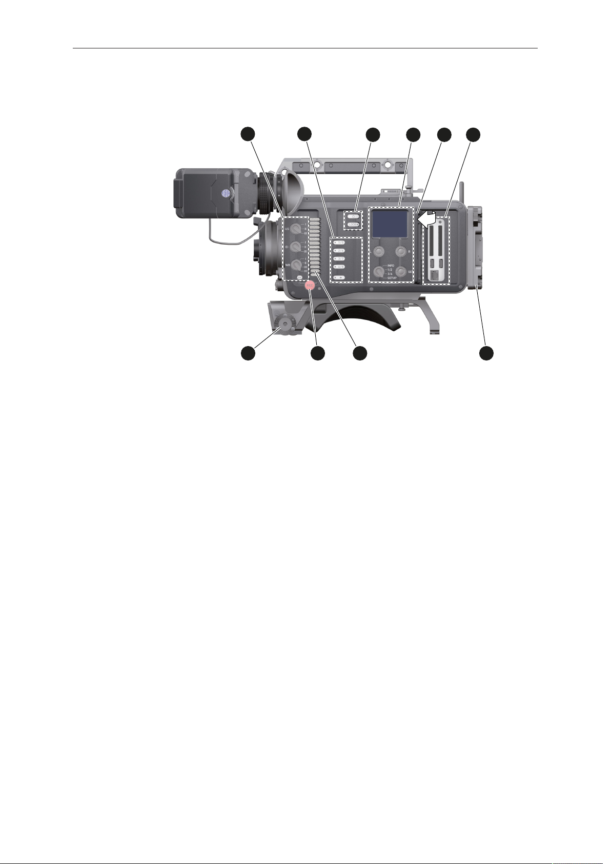
Right
1 BAT power input 6 RS connector
2 I/O panel 7 Bracket rosette
3 Audio connector panel 8 WPA-1 with quick release connectors
4 Fan intake 9 Fan outlet
5 12-pin Hirose for ENG type lenses
Page 16
16 Camera parts and controls
1
2
3
4
5
6
7
8
9
10
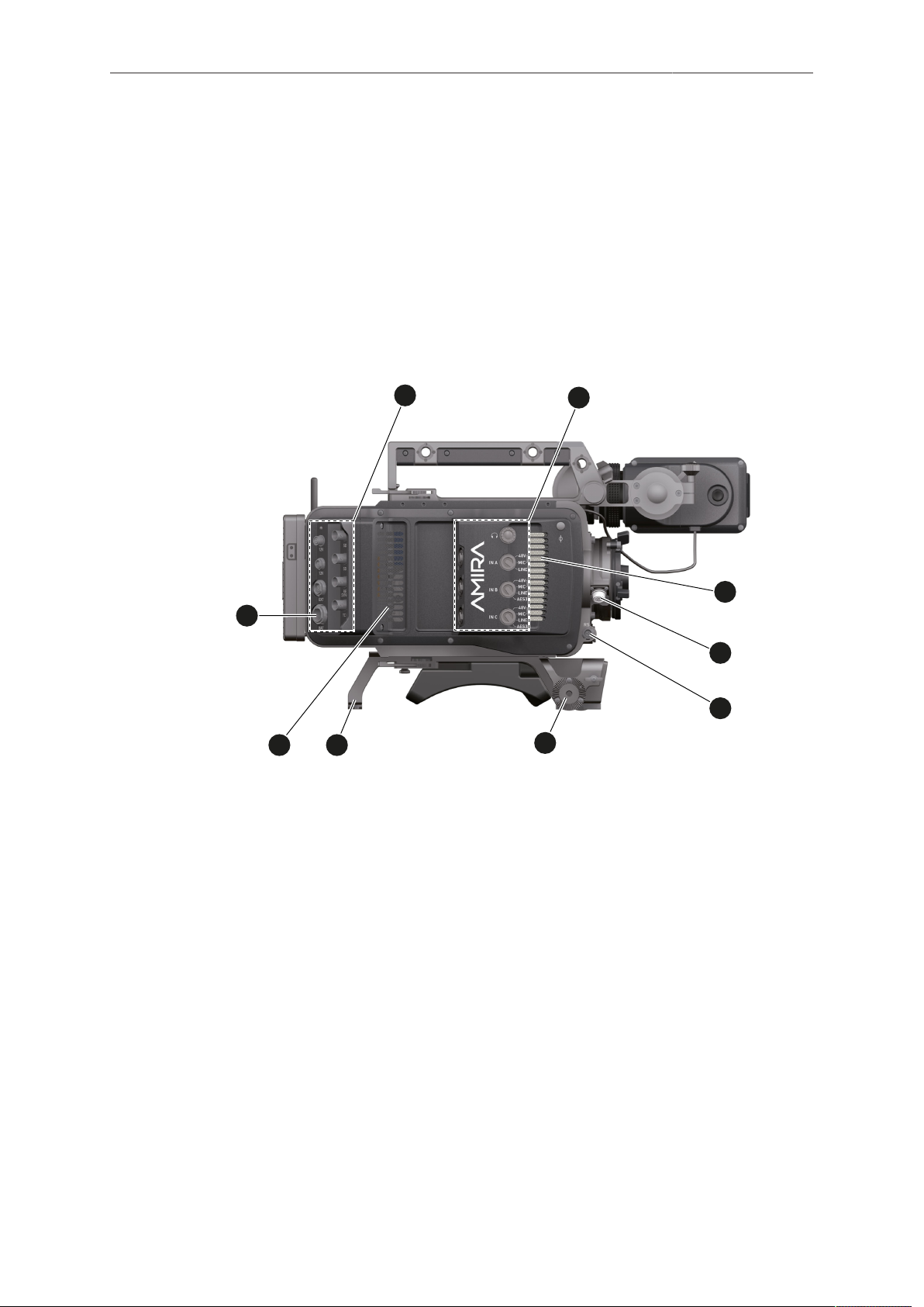
Left
1 Operator panel
2 User buttons
3 Power button & camera lock
4 Audio control panel
5 Lid
6 Media panel (behind lid)
7 Battery adapter
8 Fan intake
9 Recording button
10 Bracket rosette
Page 17
Camera parts and controls 17
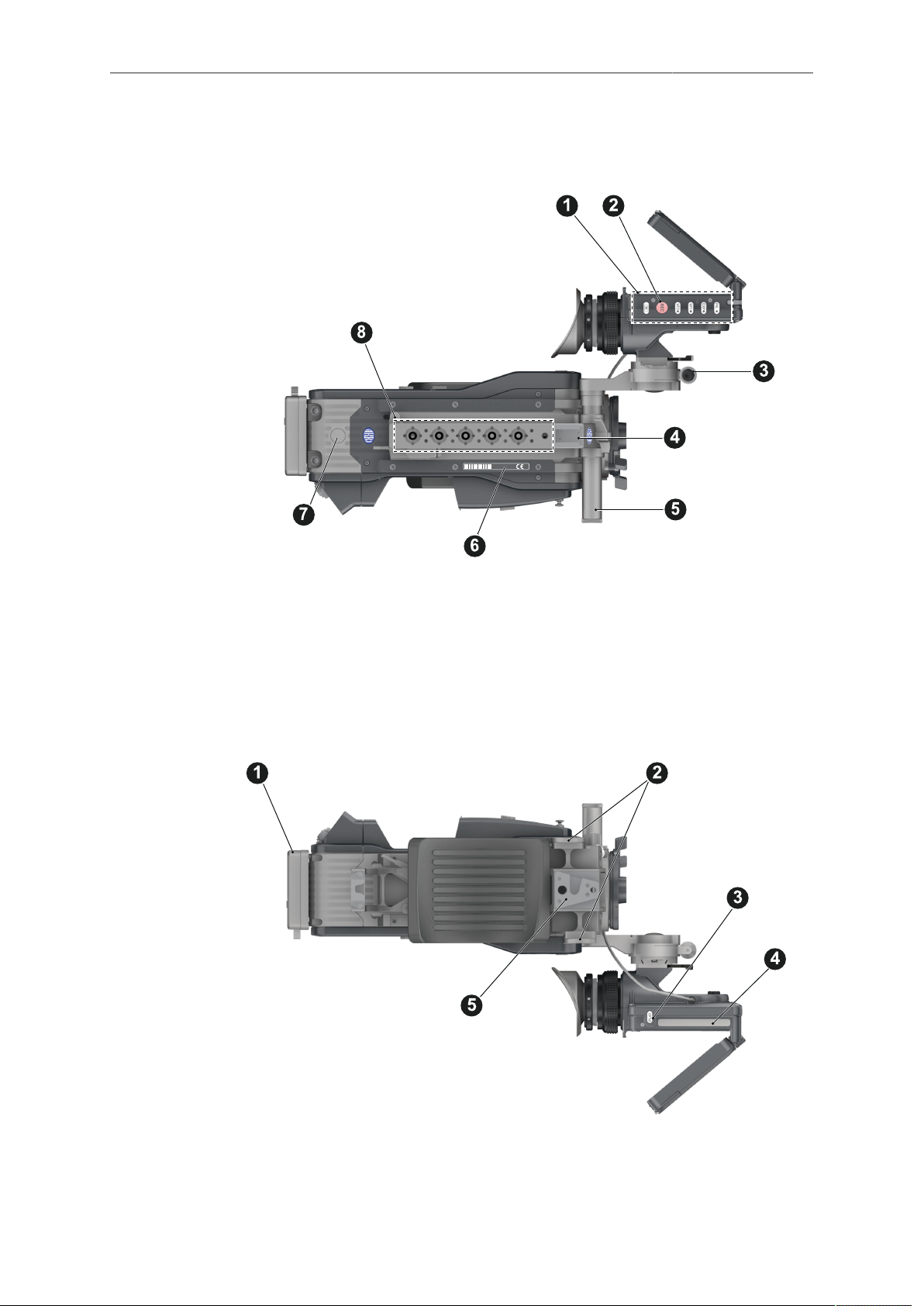
Top
1 Viewfinder top buttons 5 Adjustable beam
2 Recording button 6 Camera type label
3 Viewfinder hinge with clamp 7 Level
4 Accessory shoe 8 3/8" accessory threads on camera handle
Bottom
1 Battery adapter 4 Viewfinder type label
2 Bracket rosettes 5 WPA-1 quick-lock bracket
3 PLAY button
Page 18
18 Camera parts and controls
1 2
3
4
5
6
7
8
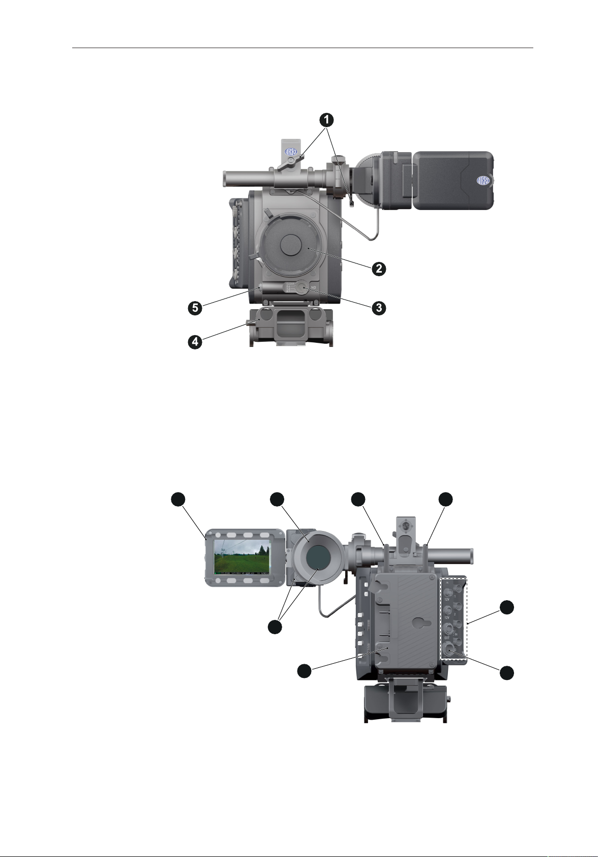
Front
1 Clamps 4 15 mm rod receptacles
2 Lens mount (here: PL) 5 RS connector
3 ND filter switch
Back
1 Fold-away monitor (viewfinder/GUI) 5 I/O panel
2 EVF OLED eyepiece 6 BAT power input
3 Bluetooth antenna 7 Battery adapter (here: Gold Mount)
4 WiFi antenna 8 Proximity sensor for OLED eyepiece
Page 19
Camera parts and controls 19
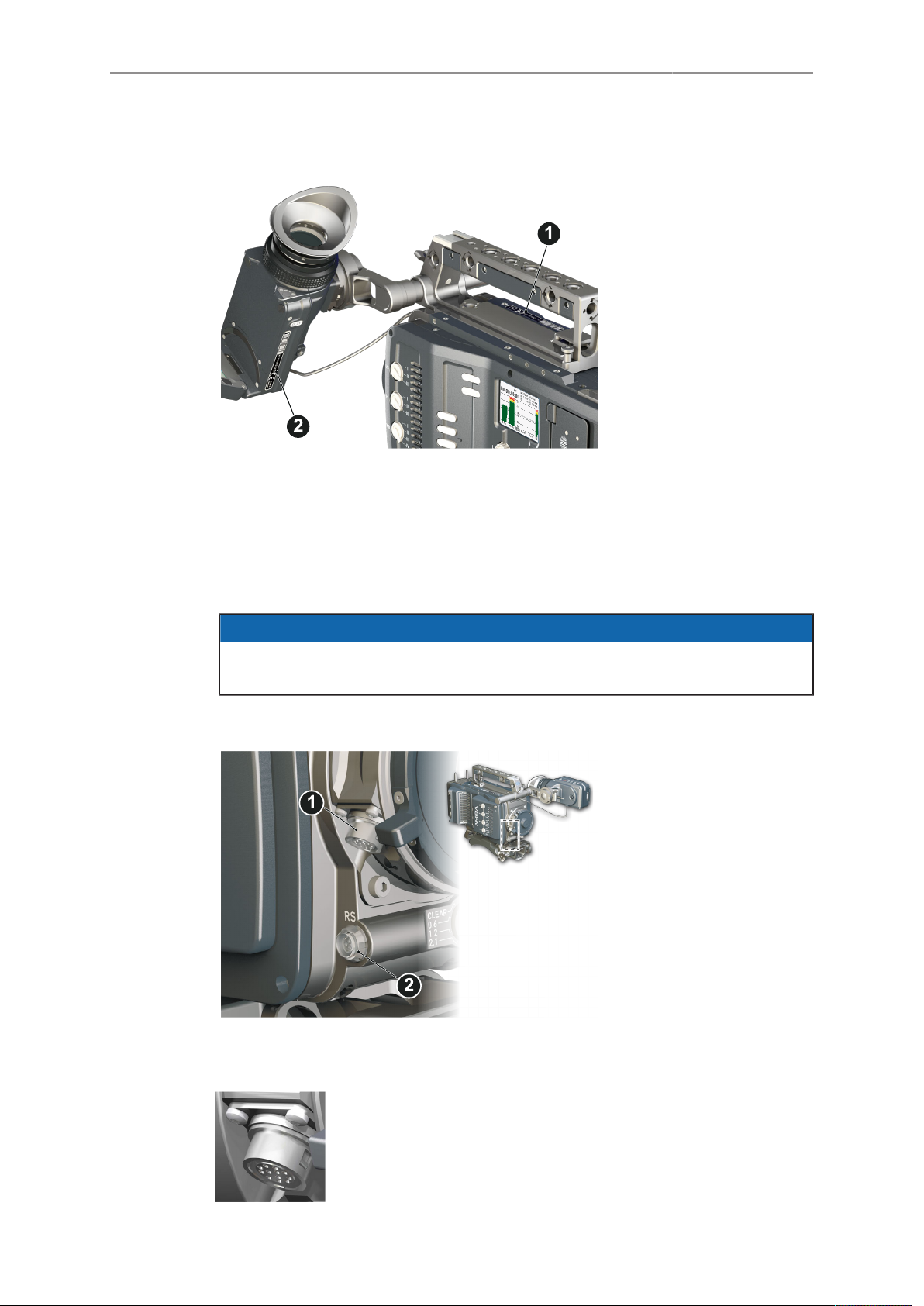
4.2 Product identification
CE type labels with serial number are on the camera top (1) and under the viewfinder
(2). The serial number consists of the last 5 digits of the equipment number
K1.71700.0-XXXXX. An FCC conformity label is on the bottom of the camera.
4.3 Connectors
Connecting or disconnecting devices or cables while recording can disturb the
audio/image signal due to static electricity.
4.3.1 Front connectors
NOTICE
1 12-pin Hirose for ENG type
lenses
2 3-pin Fischer RS
ENG (12-pin Hirose)
Supplies lens servos with power and provides access to lens servo functions.
Page 20
20 Camera parts and controls
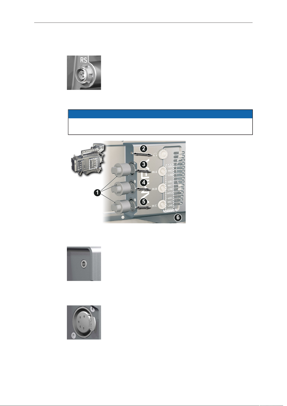
RS (3-pin Fischer)
This 3-pin Fischer socket for RS input supplies external accessories with 24 V power (2.0 A). It also carries a frame pulse output and accepts an ARRI remote start/stop trigger.
4.3.2 Audio connector panel
NOTICE
Rubber caps protect the XLR connectors from dirt and moisture. Always cap
unused XLR connectors.
1 Protective caps
2 Headphone out & volume
3 XLR 5-pin audio input
4-5 XLR 3-pin audio input
6 Input signal options
Headphone
IN A (5-pin XLR)
Headphone 3.5mm stereo TRS (“Mini-jack”) output for monitoring
audio channels.
XLR input for microphone signals (including 48V phantom power
supply) and line level signals.
Page 21
Camera parts and controls 21
IN B & C (3-pin XLR)
XLR input for microphone signals (including 48V phantom power
supply), line level signals and AES3 digital.
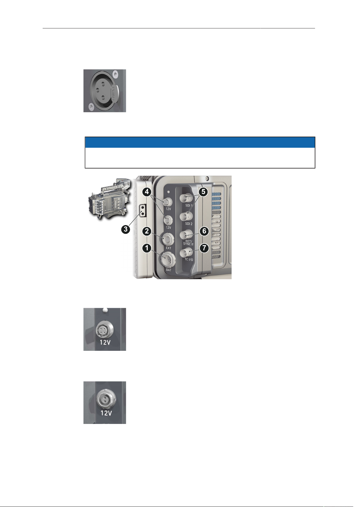
4.3.3 I/O panel
NOTICE
If the power supply to BAT is interrupted with the camera switched on, the camera
will automatically repower and boot-up on reconnection.
1 BAT main power in
2 EXT in/out
3 D-tap (optional)
4 Aux power out
5 HD-SDI image out 1 and 2
6 Return/sync in
7 Timecode in/out
12V (4-pin Hirose)
Supplies 12 V auxiliary power with a maximum power of 2.0 A
(combined output of 4-pin Hirose and 2-pin LEMO).
12V (2-pin LEMO)
Supplies 12 V auxiliary power with a maximum power of 2.0 A
(combined output of 4-pin Hirose and 2-pin LEMO).
Page 22
22 Camera parts and controls
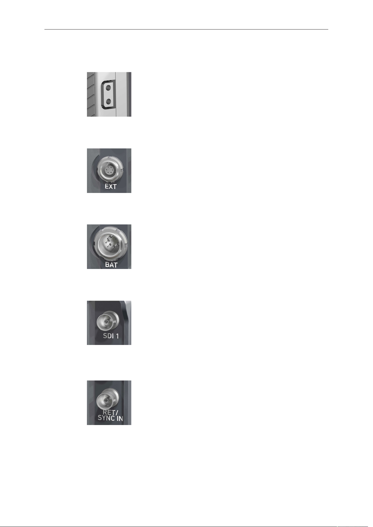
D-tap
A D-tap on the battery adapter supplies accessories with 12 V
DC from the camera.
EXT (6-pin LEMO)
A connector for external accessories, with two CAN buses and
accessory power output at camera voltage level (2.0 A max.).
BAT (8-pin LEMO)
Via cables KC50-S (2 m, straight) and KC50-SP-S (coiled), this
main power supply input accepts 10.5 to 34 V DC.
SDI OUT 1 & 2 (BNC)
Both BNC sockets (here: SDI 1) deliver image outputs in
1920x1080 422 1.5G, 422 3G and 444 3G single link formats.
SDI 2 also supports the 3840x2160 422 6G format in 4K UHD
mode.
RET/SYNC IN (BNC)
A BNC socket for Genlock input, or HD-SDI return image signal
(configurable). Supports Black Burst, Tri-Level Sync and HD-SDI
genlock signals.
You can feed HD-SDI return signals from another image source
to the camera RET connector. The signal must be a 1920x1080
422 1.5G SL according to SMPTE 274M and 292M. Via the camera menu, you can set the output routing of the RET in signal.
Page 23
Camera parts and controls 23
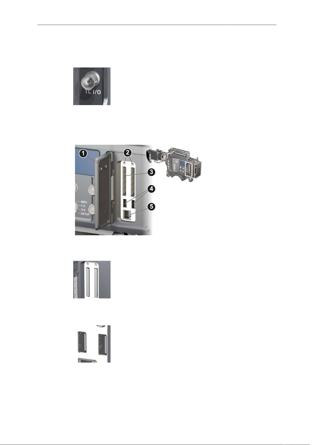
TC I/O (BNC)
A Timecode in-/output (BNC interface) to be configured via camera menu.
For external TC feeds to the camera.
•
Note: If Black Burst or Tri-level sync signals are not available,
the camera can be configured to use the TC signal itself as
Genlock.
Note: The camera has a TC buffer to keep a synced free run
TC for up to 10 minutes when power is disconnected.
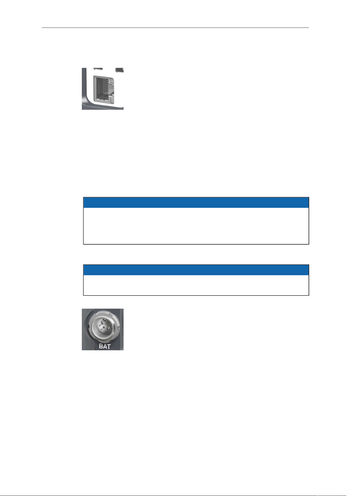
4.4 Media panel
1 Lid
2 Status LEDs
3 CFast 2.0 card slots A & B
4 USB in/out 1 & 2
5 RJ45 Ethernet
Card A & B (CFast 2.0)
Storage media slots for CFast 2.0 recording cards.
USB 1 & 2
Interface for USB memory sticks with FAT file system. Can also
be used to charge USB devices. Each port supplies 5V with a
maximum current of 500mA.
Note: Only one USB memory stick can be used at a time. Independent of slot, the first stick connected becomes active. Meanwhile, the second slot can still be used to charge a device.
Page 24
24 Camera parts and controls
Ethernet LAN
RJ45 LAN interface for remote control of the camera, for multicam control and for service access.
4.5 Power supply
Depending on your battery demand, the camera offers either a Gold Mount or a VLock adapter. You can change both yourself. For more information, see "Mounting and
unmounting the battery adapter", page 37). For further details, see our website or
ask your local ARRI Service Partner.
The camera accepts an input voltage range from 10.5 to 34 V DC. Do not supply
power outside the specified voltage range.
NOTICE
For maximum operation time, always use fully charged batteries with 10.5 to 34 V
DC (50 W minimum).
Always keep the BAT connector or attached battery accessible so that they can be
unplugged quickly in case of emergency.
4.5.1 BAT in
NOTICE
If the power supply to BAT is interrupted with the camera switched on, the camera
will automatically repower and boot-up on reconnection.
Use the BAT connector, and a KC50-S or KC50-SP-S cable,
to supply the camera with 10.5 to 34 V DC. Do not use cables
longer than 4m.
4.5.2 Powering auxiliary devices via the camera
You can supply power to auxiliary devices from the camera using several connectors
(2.0 A max):
12 V via 2-pin LEMO, 4-pin Hirose, or via D-tap on battery adapter
•
24 V via RS
•
Camera voltage via EXT
•
Note: For connector pin-out information, see appendix. When the power supply level
is critical, the camera switches off all auxiliary power supplies first.
Page 25
Camera parts and controls 25
4.6 Camera Controls
The camera body has several buttons and switches to control the camera. They are
explained in detail in the following chapters.
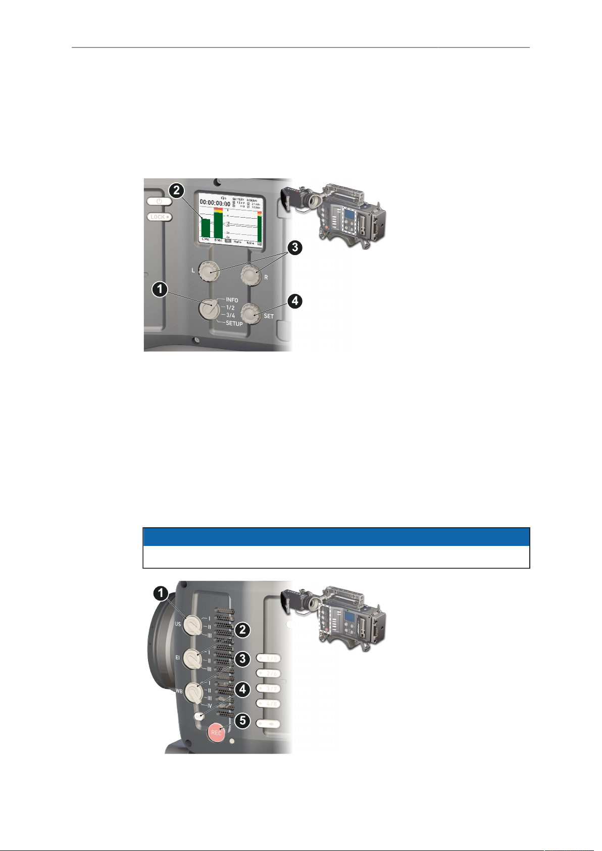
4.6.1 Audio control panel
1 Audio function switch
2 Audio display
3 Left/right gain controls
4 Audio SET jogwheel
4.6.2 Operator panel
The operator panel consists of switches that offer quick adjustments to important
camera functions, such as exposure index or white balance.
For all switch positions (except ND positions), you can assign an individual preset.
See the next chapter for full instructions.
The EI and WB switches are assigned to exposure index and white balance
respectively. Permanent switch icons on the EI and WB soft buttons on the home
screen indicate this permanent assignment.
One of the functions FPS, SHUTTER, or LOOK can be assigned to the user switch
(US). A switch symbol appears on the home screen next to the soft button of the
assigned function.
You can only edit the value of the currently active switch position.
NOTICE
1 User switch & settings
2 Exposure switch & settings
3 White balance switch &
settings
4 Auto-white balance button
5 Recording button & LED
Page 26
26 Camera parts and controls
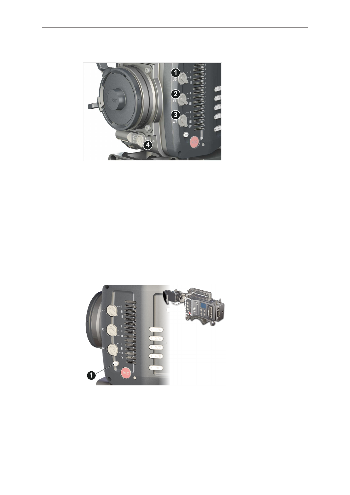
4.6.2.1 Operator switches
The EI switch (2) is dedicated to exposure index. WB (3) is dedicated to white balance
and ND (4) to filtering.
The US switch (1) can be assigned to control either FPS, SHUTTER, or LOOK. For
more information, see "Setting the user switch function", page 138.
The switches have three (US, EI, ND) or four positions (WB). Except for ND (4), you
can modify the switch position presets.
4.6.2.2 AW auto white balance button
The AW button triggers the auto white balance functionality: based on the camera's
live image, AW calculates an automatic white balance and overwrites the active WB
settings. The result is also stored as the preset value of the active WB position and in
the first entry of the WB list.
AW triggering
► Note: Under or overexposed images may cause the auto white balance to fail.
Always trigger auto white balance with properly exposed images.
► To trigger an automatic white balance: press AW twice in a second (1).
Page 27
Camera parts and controls 27
► Two AW modes, Matrix and Center, are available.
Matrix mode: Full-image-based, the algorithm determines the image content
°
best suited to white balance calculation.
Use for regular image content.
Center mode: Calculates the white balance based on the center area of the
°
image.
Use with a gray card placed in the image center. For accurate results: fill the
entire area with the gray card.
The camera displays an image overlay showing the center area used for
calculation.
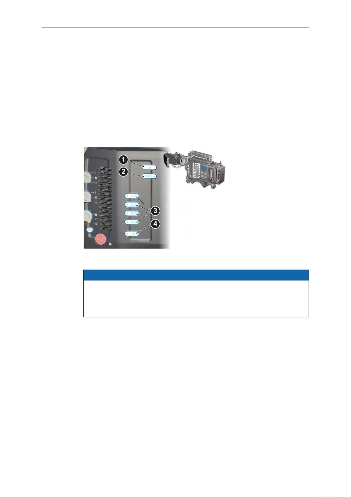
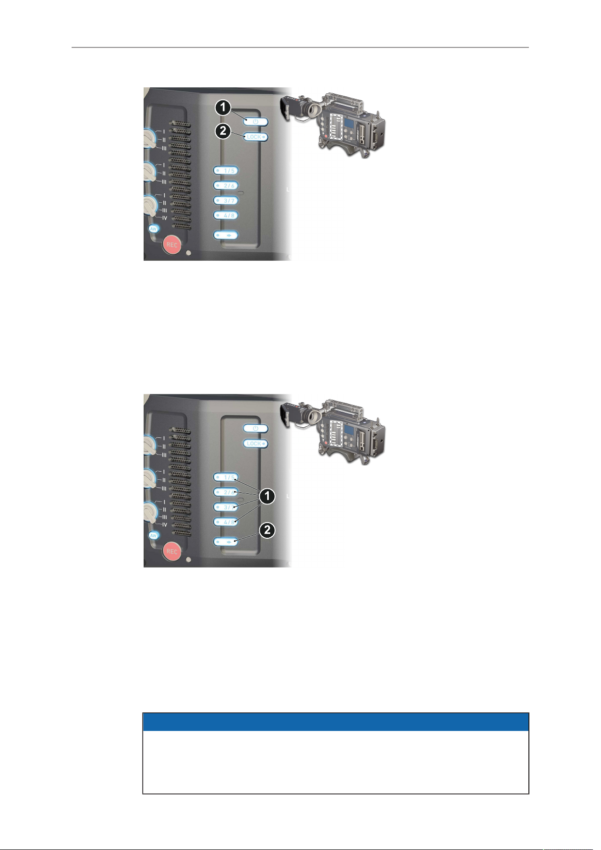
4.6.3 User buttons panel
1 Power button
2 Camera lock
3 User buttons
4 SHIFT button
4.6.3.1 Locking and unlocking the camera
NOTICE
Locking the camera disables, unlocking re-enables all camera controls configured
for locking except audio controls.
Changing the position of the US, EI, WB, or ND switch on a locked camera will
result in parameter changes when unlocking.
For details on lock configuration, see "Buttons and display", page 119.
Page 28
28 Camera parts and controls
1. Press and hold LOCK (2).
2. A countdown appears in both the monitor and viewfinder. The camera locks as
soon as the countdown reaches zero.
3. To unlock: Press and hold LOCK (2) again.
4.6.3.2 User buttons
The camera menu allows you to assign individual functions to each user button.
1. Press a button (1) to trigger its function.
2. For buttons five to eight: Press and hold SHIFT (2); then press a button (1).
3. An LED on each button reflects the functional status.
4. To check the functional status of buttons five to eight (1): Press SHIFT (2).
For information on how to assign functions to user buttons, see "User buttons",
page 135.
4.6.4 Starting recording via REC button
NOTICE
Pressing a recording button returns the MVF-1 user interface to the home screen
and disables the menu access.
Recording also disables the US switch and the home screen buttons for FPS, TC,
Shutter, and Look settings.
Page 29
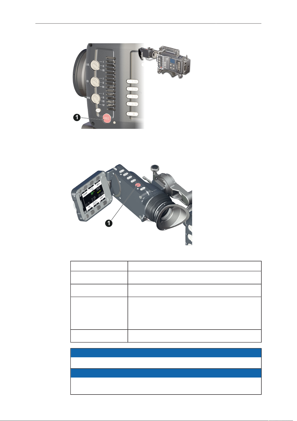
Camera parts and controls 29
The REC button is located on the left side of the camera.
An additional REC button is located on the viewfinder and the Camera Control Panel
CCP-1, if mounted.
The run LED next to the REC button on the camera body reflects the camera's status.
Run LED is... Camera is...
solid green ready for recording
solid red recording
off not ready for recording. Check if the CFast 2.0 card is
valid.
For more information, see "Camera preparation",
page 36.
flashing green/red not ready for recording due to an error.
NOTICE
Never change memory cards when recording - this may damage the recorded clip.
NOTICE
Connecting or disconnecting devices or cables while recording can disturb the
audio/image signal due to static electricity.
Page 30
30 Camera parts and controls
1
2
3
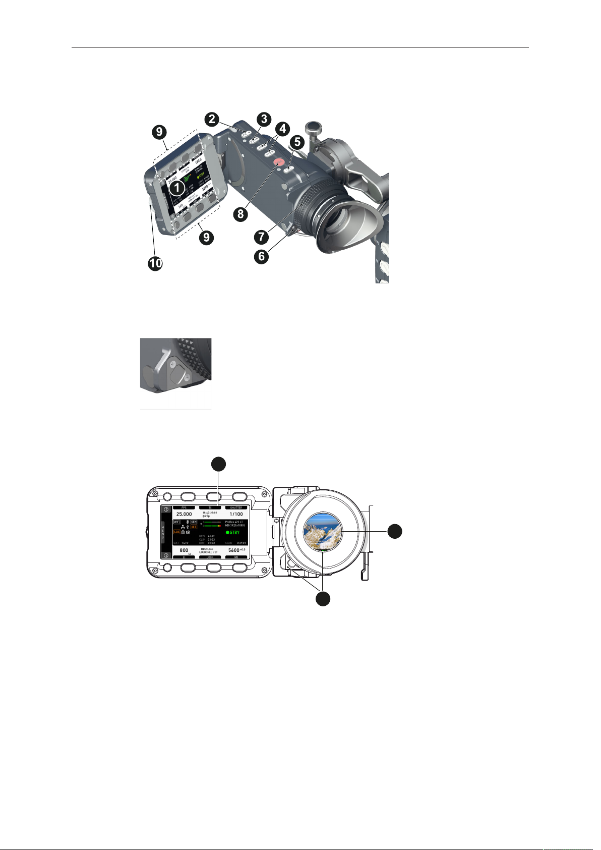
4.6.5 MVF-1 controls and proximity sensor
1 Monitor (Live & GUI)
2 Peaking button
3 Exposure tool button
4 VF1 & VF2 user buttons
5 Monitor button
6 Proximity sensor
7 Diopter control
8 Recording button
9 Screen buttons
10 Jogwheel
Proximity sensor
4.6.5.1 EVF and Monitor
When you put your eye against the eyepiece, the proximity sensor (3) activates the
EVF (2).
You can configure the camera to show status information on the EVF (2).
When activated, the camera shows essential camera, audio, and recording
parameters next to the image.
You can modify/deactivate the status information via the EVF overlays and EVF status
components menu. For more details, see "Status info", page 98.
Note: If surround view is active, the surround area is marked by a separating line or a
surround mask.
The infrared proximity sensor automatically deactivates the
viewfinder's internal OLED panel when you take your eye off it.
The sensor is placed either on the bottom left-hand side of the
viewfinder (generation 1, shown in image), or it is integrated into
the eye cup (generation 2, not shown).
Note: To avoid hardware damage, always keep the proximity
sensor unobstructed.
Page 31

Camera parts and controls 31
4.6.5.2 Adjusting the diopter
► Twist the ring left or right for diopter adjustment (1).
4.6.5.3 Adjusting the monitor
► Fold out (1), swivel (2) and fold in (3) the monitor to put the display visible in the
folded-in position.
Page 32

32 Camera parts and controls
1
1
4.6.5.4 Changing the monitor mode
► Press the M button (1) to change the monitor mode between live view and user
interface.
► In live mode, press the lower screen buttons (1) to toggle the status bar content.
You can disable the location sensor that automatically flips the user interface to match
a left or right-side monitor position (3).
► Choose Menu > Monitoring > EVF/Monitor > Settings > Monitor flip mode.
Page 33

Camera parts and controls 33
1
2
4
3
4.6.5.5 User monitor
Screen buttons and jogwheel
There are eight screen buttons, four above (2) and four below (3) the display (4). Their
function depends on the screen content (4) and is labeled directly above or below
each button.
Unlabeled buttons do not have a function for that screen. A grayed-out label shows
that the function is currently not available. Using the jogwheel (1), you can do the
following:
Scroll or navigate through lists and menus.
•
Change values (by scrolling up or down).
•
Confirm settings (by pressing the jogwheel).
•
On the home screen (4), press the jogwheel (1) to open the camera menu.
4.6.5.6 Adjusting the monitor brightness
► Choose MENU > Monitoring > EVF/Monitor > Settings.
For more information, see "Defining EVF/Monitor settings", page 111.
4.6.5.7 Assigning a function to VF1 & VF2 user buttons
Page 34

34 Camera parts and controls
The MVF-1 has two user buttons, VF1 and VF2 (1). You can assign frequently-needed
functions to each button.
► For more information, see "Button VF1 and VF2", page 138 .
4.7 CCP-1
The Camera Control Panel-1 (CCP-1) is a standalone control panel, containing the
display and a subset of the buttons of the MVF-1. It shows either the user interface or
live view, and the buttons reflect the behavior of the equivalent buttons of the MVF-1. It
can be used as the only control panel or with a MVF-1 daisy-chained to it.
1 Recording button 4 Monitor button
2 VF-1 user button 5 Play button
3 VF-2 user button 6 Jogwheel
For more information on connecting the CCP-1 to the camera, see "Connecting the
CCP-1", page 47 .
4.8 Lens mount/filters
1 Lens mount (here: PL LDS
Lens Mount)
2 ND filter switch (clear - 0.6
- 1.2 - 2.1)
Page 35

Camera parts and controls 35
LDS
The camera supports the ARRI Lens Data System (LDS). Lenses with built-in LDS
functionality communicate their focus, iris, and zoom values to the camera where the
data is stored as metadata in the recorded files. The lens data can also be displayed
as part of the status information. For more information, see "Setting EVF/SDI status
info components", page 103.
Cooke /i support
The camera supports the Cooke /i protocol for lenses running firmware versions
according to the following table.
Lens type FW version
S4 /i Prime lens (10-bit) 0.29 or higher
S4 /i Prime lens (12 bit) 0.39 or higher
S4 /i Zoom lens (10 bit) 1.29 or higher
S4 /i Zoom lens (12 bit) 1.39 or higher
The firmware version can be retrieved from the lens with the Cooke Viewer Lens
Display program. For detailed information, please contact Cooke Optics directly.
4.8.1 Lens iris control
You can control the lens iris with ENG-style lenses (B4 and PL) and EF lenses. You
can control the iris via the auto iris feature or manually via user buttons or the menu
(EF lenses only).
For more information, see
"Adjusting the iris (EF lenses) manually", page 77
•
"Defining the auto iris calculation", page 77
•
"User buttons", page 135
•
"EF lens support", page 35
•
4.8.2 EF lens support
With the EF mount the camera supports a wide range of EF lenses from Canon,
Sigma, Zeiss and other manufacturers.
Apart from the common features for controlling lenses, the camera also supports the
following features:
Image stabilization
•
The lens image stabilizer for EF lenses is supported.
Iris and focus control
•
If you are using the Wireless Compact Unit WCU-4 or Master Grips from the ARRI
Electronic Control System (ECS) range, you can control EF lenses as follows:
Axis Master Grip WCU-4
Iris X X
Focus X
Page 36

36 Getting started
5 Getting started
The next section gives you information on the basics of how to prepare the camera for
use.
5.1 Camera preparation
The following chapters provide information on how to attach commonly used
accessories to the camera.
NOTICE
To avoid damage while assembling and retrofitting, always place the camera on a
padded, firm, flat and level surface.
Work on an unpowered camera only.
5.1.1 Mounting to a bridge plate
NOTICE
Always use a flat screwdriver to connect the BPA-3 to a bridge plate. Never use a
coin. A coin does not deliver enough force to ensure a proper lock.
1. For mounting to a bridge plate, use the BPA-3 bridge plate adapter.
2. Place the bridge plate unter the adapter (1).
3. Adjust the bridge plate's nose (3) to the adapter's aperture.
4. With a flat screwdriver (no coin!), attach the screws to the adapter and tighten (2).
5. Note: Always ensure a proper lock.
Page 37

Getting started 37
5.1.2 Mounting to a wedge plate
1. For mounting to a wedge plate, use the WPA-1 wedge plate adapter.
2. Open the quick-release base plate.
3. Place the adapter (1) into the quick-lock plate slighty behind the connection points.
4. Slide the camera forward until the quick-lock audibly locks (2).
5. Note: The lock must be closed.
5.1.3 Mounting and unmounting the battery adapter
Tools needed
2.5 mm Allen key
•
Page 38

38 Getting started
Mounting
1. Note: The illustration shows a V-Lock adapter.
2. Switch off; interrupt the power supply.
3. Pin the battery adapter (1) to the camera.
4. With a 2.5 mm Allen key, fasten all three screws (2) handtight until the adapter fits
tightly.
Page 39

Getting started 39
Unmounting
1. Note: The illustration shows a Gold Mount adapter.
2. Switch off; interrupt the power supply.
3. With a 2.5 mm Allen key, unfasten all three screws (2).
4. Remove the battery adapter (1).
Page 40

40 Getting started
5.1.4 Changing a Gold Mount battery
1. Place the battery pins in the mount receptors (1).
2. Slide the battery (2) to the right until the adapter audibly locks (1).
3. To release: With the lever pushed (3), slide the battery (2) to the left and
backwards.
Page 41

Getting started 41
5.1.5 Changing a V-Lock battery
1. Place the battery's wedge into the V-shaped lock (1).
2. Slide the battery (2) downwards until the adapter audibly locks (1).
3. To release: With the pin pushed (3), slide the battery (2) up- and backwards.
Page 42

42 Getting started
5.1.6 Mounting and unmounting the base adapter
Mounting
1. Note: The illustration shows a WPA-1.
2. Open the clamp (1).
3. Slide the adapter under the camera (3).
4. Note: The safety pin (2) must audibly lock.
5. Close the clamp (1).
Page 43

Getting started 43
Unmounting
1. Note: The illustration shows a BPA-3.
2. Open the clamp (1).
3. With the safety pin pulled (2), slide the adapter off the camera (3).
5.1.7 Mounting and unmounting the camera handle
1. Open the clamp (1).
2. Slide the handle onto the camera (2).
3. Note: The safety pin (3) must audibly lock.
Page 44
44 Getting started
4. Close the clamp (1).
5. To unmount: Open the clamp (1).
6. With the safety pin pulled (3), slide the handle off the camera (2).
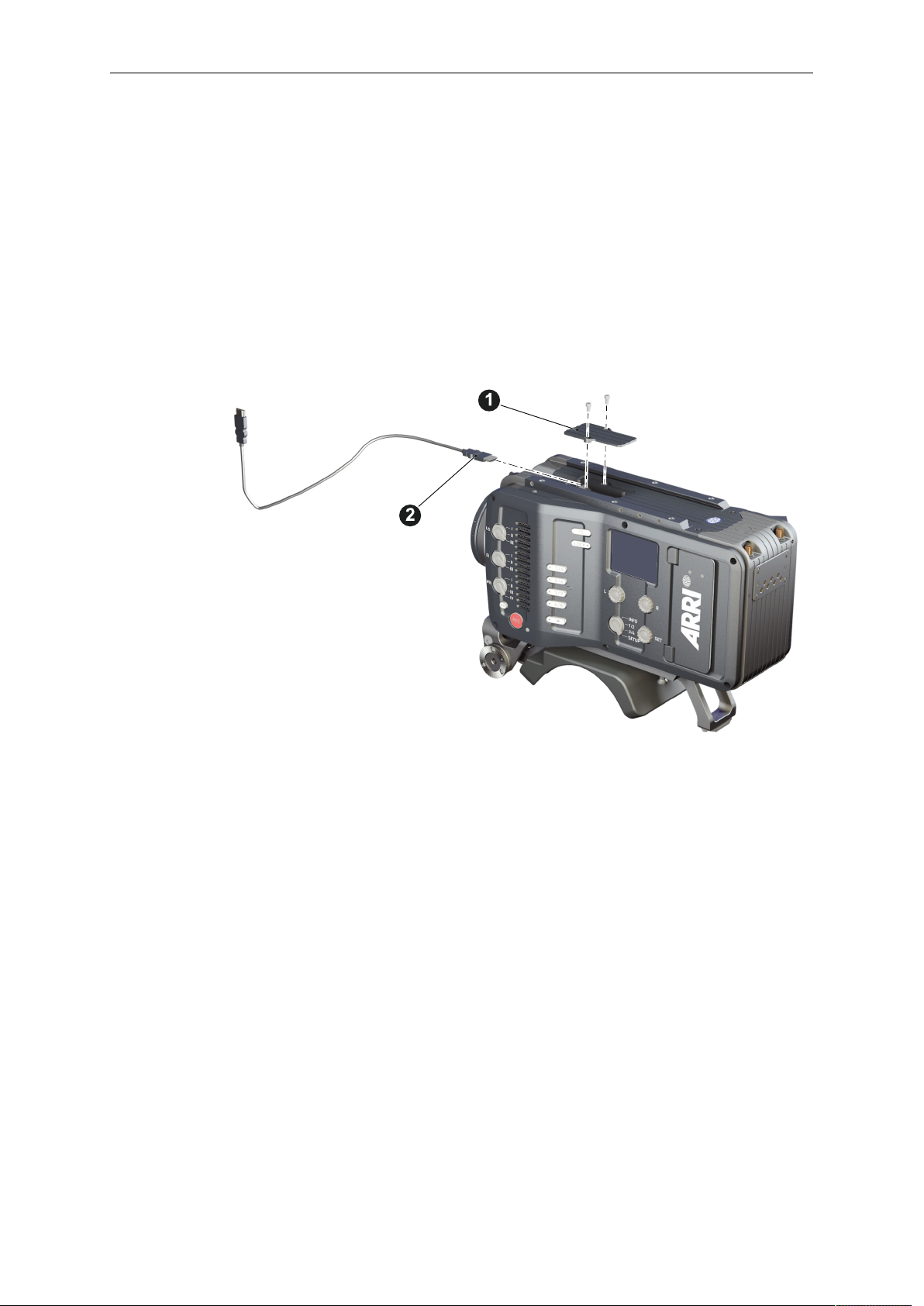
5.1.8 Changing the viewfinder and the EVF cable
Tools needed
2 mm Allen key
•
Changing the EVF cable
1. Note: Use original AMIRA EVF cables only.
2. Place the camera bottom-down.
3. Unmount the camera handle. See page 43.
4. With a 2 mm Allen key, unscrew and remove the lid (1).
5. Either: Connect the cable (2) to the EVF port.
6. Or: Disconnect the cable (2).
7. Reattach lid (1) and camera handle.
Page 45

Getting started 45
Changing the viewfinder
1. Switch off; interrupt the power supply.
2. Note: Use original AMIRA EVF cables only.
3. Connect an EVF cable to the camera. See page 44.
4. With your fingers, unscrew and remove the viewfinder’s lid (1).
5. Either: Connect the cable (2) to the EVF port.
6. Or: Disconnect the cable (2).
7. Reattach the lid (1).
Page 46

46 Getting started
8. Open the clamp (1).
9. Either: Dovetail the viewfinder to the bracket (2).
10. Or: Unbracket (2) and remove the viewfinder.
11. Close the clamp (1).
5.1.9 Adjusting the viewfinder
1. Slightly loosen the clamp (1) to move the viewfinder (2) left/right and up/down.
2. Unclamp the hinge (3) to swivel the viewfinder horizontally.
3. Close all clamps (1, 3) when the viewfinder is in the desired position (2).
Page 47

Getting started 47
5.1.10 Connecting the CCP-1
1 MVF-1 connector
2 CAM connector
Connect CCP-1 to the HDMI connector on camera top side, located below the camera
handle.
When it is used alone with the camera, it always shows an image.
When a MVF-1 is daisy-chained to the CCP-1, the MVF-1 will show an image in the
EVF, but only one of the two monitors, either of the MVF-1 or the CCP-1 is active.
If the monitor of the MVF-1 is closed, the CCP-1 is activated.
If the monitor of the MVF-1 is opened, the monitor will be activated.
Activate the MVF-1 by pressing a screen button on the MVF-1.
•
Activate the CCP-1 by pressing any button except the REC button on the CCP-1.
•
Page 48
48 Getting started
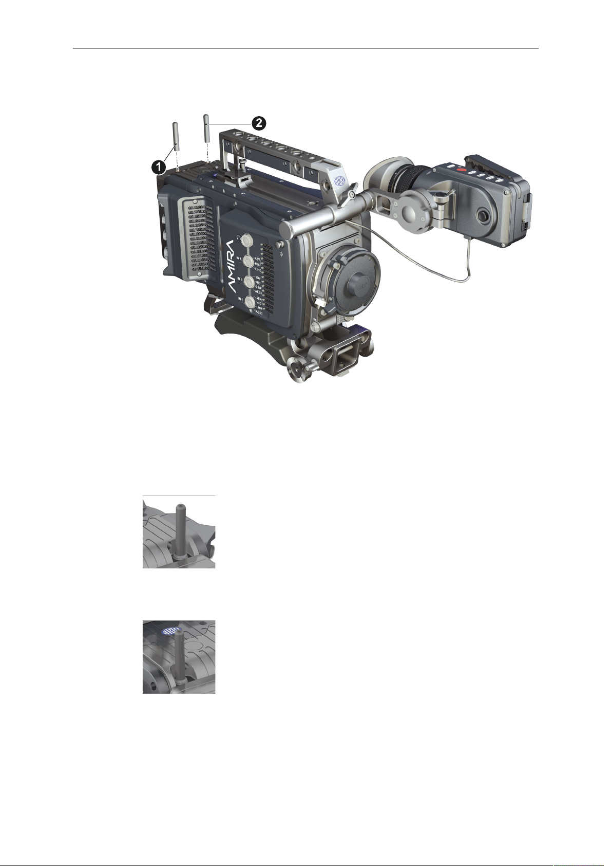
5.1.11 Mounting and unmounting antennas
1. With your fingers, thread the antennas for WiFi (1) and Bluetooth (2) onto the
camera.
2. To unmount: Unthread the antennas (1, 2) with your fingers.
WiFi
Antenna for WiFi signal according 802.11g. Used for remote
camera access.
Bluetooth
Antenna for Bluetooth signal. Used for wireless audio monitoring
and comment channel return with Bluetooth headset. Supports
Handsfree and A2DP protocols.
5.1.12 Mounting and unmounting the microphone bracket
Tools needed
3 mm Allen key
•
Page 49

Getting started 49
1. With a 3 mm Allen key, attach the microphone bracket (1) to the handle (2).
2. To unmount: Loosen the screw (2); remove the bracket (1).
5.1.13 Connecting and disconnecting audio devices
Connecting audio devices
1. Uncap the needed connectors only (1).
2. Connect the headphone (2).
3. Set the headphone volume by turning the wheel (2).
4. Alternatively, you can use the SET wheel on the camera's left. See "Adjusting the
headphone volume", page 140.
5. Via switches (3 to 5), select the appropriate setting for your audio device (6):
48V: Analog microphone level signals with phantom power supply
°
MIC: Analog microphone level signals
°
Page 50

50 Getting started
LINE: Analog line level signals
°
AES3: Digital AES/EBU signals
°
6. Connect each device (3 to 5) until the connector audibly locks.
Disconnecting audio devices
1. Press the PUSH button to unlock (1).
2. Remove the cable by pulling on the connector.
3. Replace with another cable.
4. Or: Cap the connector for protection.
5.1.14 Changing a lens mount
High voltage! Risk of electric shock and fire!
Short circuits may entail lethal injury and damage!
Use original AMIRA or ALEXA Mini lens mounts only.
Before each lens mount change, always switch the camera off and disconnect all
power sources.
Changing the lens mount while the camera is powered may permanently damage
the camera and lens mount.
Protect sensor and electrical system: Always store the camera with a lens mount
properly installed and capped.
Immediately replace each lens mount after removal.
Change lens mounts in dust-free environment only.
DANGER!
NOTICE
After each lens mount change, always check the back focus of the camera.
Have the back focus always corrected by properly skilled personnel.
Back focus correction requires special tools and training that meet ARRI guidelines.
For all back focus issues, contact a qualified ARRI Service Center.
Tools and provisions needed
3 mm Allen key
•
Switch the camera off
•
Page 51

Getting started 51
Disconnect all power sources
•
Properly cap, disconnect, and store the lens
•
Perform the task with care to protect all optical surfaces
•
Uninstalling a lens mount (here: PL mount)
1. Crosswise, loosen all four screws (2) with an Allen key.
2. Carefully remove the mount (1).
3. Store the mount in a case for dust protection.
4. Note: To protect the sensor (3), immediately install another lens mount.
Installing a lens mount (here: PL mount)
WARNING!
Condensation! Risk of electric shock and damage!
Humidity may ingress due to misinstalled lens mounts!
When installing a lens mount, always align and attach properly; never apply force.
Hand-tighten all screws crosswise before final tightening.
Always tighten crosswise with the prescribed tool.
1. Properly align the two guiding pins (1) for correct lens mount fit (2).
2. Note: Never apply force, align the guiding pins instead.
Page 52

52 Getting started
3. Crosswise, hand-tighten all four screws (1).
4. Only then, tighten all screws crosswise with an Allen key.
5. Note: Always store the camera with a lens mount properly installed and capped.
The titanium PL LDS mount with LBUS connector (K2.0003216) does not supply
LBUS functionality nor lens data via the LDS contacts when attached to the AMIRA.
5.1.15 Changing a lens
Protect the sensor: Always keep a lens or protective cap on the empty lens mount.
Change lenses in dry, dust-free environments only.
Never exceed the maximum lens dimensions.
Have every lens properly shimmed as prescribed by the manufacturer.
PL mount
NOTICE
NOTICE
1. Observe maximum lens dimensions.
2. Unlock the lens mount counter-clockwise (1) and remove the lens or cap.
3. Never touch the sensor.
4. Either: Mount the next lens and lock (2) the lens mount clockwise.
5. Or: Always cap and lock (2) an empty lens mount clockwise.
Page 53

Getting started 53
EF mount
Note: Please use a lens support system for EF lenses above 2 kg/4.4 lbs.
1. Observe maximum lens dimensions.
2. Turn the lever counter-clockwise (1) to unlock the mount.
3. Either: Unscrew the cap.
4. Or: Press and hold the button (2) to unlock the lens.
5. Counter-clockwise, unscrew the lens (3).
6. Never touch the sensor.
7. Either: Mount the next lens:
Align the dots of both lens and lens mount.
°
Push the lens into the mount.
°
Turn the lens clockwise (5) until the bayonet locks.
°
Turn the lever clockwise (4) to tighten the lens to the lens mount.
°
8. Or: Always cap the empty lens mount.
Page 54

54 Getting started
5.1.16 Balancing the camera weight
1. Unlock (4) and slide the base adapter (3) until the camera is balanced.
2. Close the clamp (4).
3. Unclock (1) and slide the handle (2) until the camera is balanced.
4. Close the clamp (1).
5.2 Switching on and off
Switching the camera on
► Press the power button (1).
The ARRI and AMIRA logos appear in the audio display (2) and monitor (3).
Page 55

Getting started 55
Switching the camera off
► Press and hold the power button (1).
A countdown appears in the audio display, monitor and viewfinder.
On reaching zero, the camera powers off.
Page 56

56 Media usage
6 Media usage
The following chapter explains how to insert and remove CFast 2.0 cards and USB
sticks.
6.1 Inserting and removing a CFast 2.0 card
NOTICE
AMIRA does not accept ALEXA-formatted CFast 2.0 cards, and vice versa.
Before using a CFast 2.0 card with AMIRA, you must erase it in-camera to create
the required file system.
Avoid damage to the contacts of both camera and card. Always insert cards as
described in this document.
Never change memory cards when recording - this may damage the recorded clip.
1. To insert the card, open the lid (1).
2. Align the card's positive edge (3) facing the camera rear.
3. With the contact pins first, gently insert the card, until it audibly locks (2).
4. Close the lid gently (1). Never force it closed on an unlocked card.
5. To change the active card quickly, you can set up a user button. For more
information, see "User buttons", page 135.
Page 57

Media usage 57
6. To remove the card, open the lid (1).
7. Insert the card until it unlocks audibly (2).
8. Remove the card.
6.2 Inserting and removing USB medium
1. Open the media lid (1).
2. Connect a FAT-formatted USB stick (2) to the camera (3).
The USB memory stick is now ready for use with the camera.
You can remove the stick from the camera without unmounting it.
For information on preparing the USB memory stick for use with the camera, see
"Preparing USB medium", page 95.
NOTICE
The camera only supports USB memory sticks or pendrives, FAT-formatted with
MBR partition table and with a maximum capacity of 16GB. Hard drives or similar
will not be recognized.
Page 58

58 Media usage
6.3 Supported CFast 2.0 cards
List of supported CFast 2.0 cards
Card type Useable
capacity*
SanDisk Extreme Pro CFast 2.0 60GB
57 GB HDX 8.03
(SDCFSP-060G)
SanDisk Extreme Pro CFast 2.0 120GB
114 GB HDX 8.03
(SDCFSP-120G)
SanDisk Extreme Pro CFast 2.0 128GB
121 GB HDX 14.14
(SDCFSP-128G-xxxA/B)
SanDisk Extreme Pro CFast 2.0 128GB
115 GB HDX 15.01
(SDCFSP-128G-xxxD)
SanDisk Extreme Pro CFast 2.0 256GB
243 GB HDX 15.01
(SDCFSP-256G-xxxD)
SanDisk Extreme Pro CFast 2.0 512GB
512 GB CF1502AR
ARRI Edition (K2.0016648)**
Lexar Professional 3600x CFast 2.0 128GB
128 GB 20150507
(LC128Cxxxx3600)
Firmware
HDX 15.02
Lexar Professional 3600x CFast 2.0 256GB
256 GB 20150507
(LC256Cxxxx3600)
Lexar Professional 3600x CFast 2.0 256GB
(LC256Cxxxx3600G2)
*
1 GB = 109 Byte
**
SanDisk Extreme Pro CFast 2.0 512GB card with custom ARRI firmware CF1502AR will be available in
2018
256 GB 20150507
20160507
NOTICE
Due to the lower write speed on the SanDisk Extreme Pro 60GB cards, the max.
frame rates are limited at the highest data rates:
ProRes 4444 recording in 2K: 120 fps
ProRes 4444 recording in HD: 137 fps
ProRes 422HQ recording in 2K: 181 fps.
Page 59

Home screen and camera menu 59
1
2
3
4
5
6
7
7 Home screen and camera menu
The AMIRA provides many parameters to customize the camera to suit your shooting
needs. The most important parameters are shown and can be modified using the
home screen. All other parameters can be modified using the menu.
7.1 Using the on-screen keyboard
Typing names
When you are working with textual parameters on the camera, an on-screen keyboard
allows you to enter text. You can use the keyboard, for example, to enter the name of
a white balance preset.
You have the following options:
Jogwheel (1)
•
Selects or confirms characters to form a name.
Left Arrow (2)
•
Moves the cursor backwards.
ERASE (3)
•
Deletes the character to the left of the cursor.
Right Arrow (4)
•
Moves the cursor forwards.
SAVE (5)
•
Saves the entry.
CLEAR (6)
•
Clears the entire text.
Aa (7)
•
Toggles between upper and lower case.
7.2 Working with lists
For certain parameters, the camera operates with lists that come with default entries
and can be customized to suit your needs. You can add and delete entries so that only
the entries relevant for your work are listed.
Page 60

60 Home screen and camera menu
Some lists contain values that can be directly edited in the camera, while other lists
show files that can be imported from or exported to the USB medium. Lists showing
values or files installed on the camera have a blue background, lists showing ARRI
default files or files on the USB medium are shown with a gray background.
All lists have a maximum number of entries. Whenever a list is full, the ADD button is
grayed out and a message is shown. You must delete any unnecessary entries to add
new ones.
The following parameters work with lists and the values can be edited in the camera:
HOME > FPS
•
HOME > SHUTTER
•
HOME > WB
•
The following parameters work with file-based lists:
HOME > LOOK
•
MENU > Monitoring > Frame lines > Frame line
•
MENU > Setups > User setups installed
•
Maximum list sizes
The following table lists the maximum number of entries for each type of list:
List Maximum entries
FPS 16
Shutter 16
WB 16
Looks 50
Frame lines 100
User setups 20
Adding entries
1. Select one of the parameters listed above.
2. Press ADD.
3. For lists with directly editable values:
a) Enter the desired value.
b) Press ADD TO LIST.
4. For lists with files:
a) Press DEFAULTS to see the default files provided by ARRI.
b) Press USB to see the files on the USB medium.
c) Select the desired file.
d) Press the jogwheel to start the import.
Note: If a file with the same name already exists, the camera asks whether you
want to overwrite the existing file.
Page 61

Home screen and camera menu 61
Deleting entries
1. Select one of the parameters listed above.
2. Press DELETE.
The list turns red.
3. Select the entry you want to delete with the jogwheel.
4. Press the jogwheel.
The camera asks if you want to delete the selected entry.
5. Press CONFIRM to delete the selected entry or press any other button to cancel.
7.3 Home screen
The home screen gives access to essential camera parameters and statuses. The
oval screen buttons and the jogwheel allow quick parameter editing. You can return to
the home screen by pressing the HOME button.
1 MENU jogwheel 6 WB button
2 ALERT message button 7 LOOK button
3 FPS button 8 EI button
4 TC button 9 INFO button
5 SHUTTER button 10 Status section
Note: The switch icons for WB and EI (6 and 8) are always shown. For FPS,
SHUTTER and LOOK (3, 5, 7), the switch icon is shown next to the soft button of the
function that is assigned to the user switch US.
(01) MENU jogwheel
Press the jogwheel to enter the camera menu.
(02) ALERT message button
If red: Alert messages are available (critical to camera functionality). Press the round
button to read them.
(03) FPS button
FPS shows the sensor frame rate, allowing adjustments from 0.750 to 100.000
(200.000 with valid license).
Note: The maximum frame rate that can be set is dependent on the recording
resolution and the codec.
Page 62

62 Home screen and camera menu
Note: The switch icon in the black label is only shown if the US user switch is set to
FPS.
Note: If the sensor fps does not match the project rate, the FPS label turns orange
and shows an exclamation mark.
(04) TC button
Shows the current timecode values and the active project rate, allows adjustment of
timecode format and values.
Note: If timecode is forced to Rec Run, or external timecode is missing, the TC label
turns orange and shows an exclamation mark. Enter the timecode screen by pressing
the TC button to see more information on the warning.
(05) SHUTTER button
Shows shutter settings adjustable either as angle (5.0° to 356.0°) or exposure time
(1/25 to 1/8000s).
Shutter angle, sensor fps and exposure time relate as follows:
exposure time = shutter angle / (360 * fps).
The maximum shutter angle is limited by the resulting exposure time (1/25s max).
Note: The switch icon in the black label is only shown if the US user switch is set to
SHUTTER.
(06) WB button
WB shows the camera’s current white balance (i.e. the preadjusted color temperature
of a light source).
You can adjust WB from 2,000 to 11,000 Kelvin (here: 5,600) in steps of 10 K for red/
blue correction.
You can also color-compensate for green/magenta tints in a range from -16.0 to +16.0.
Positive or negative CC color compensation values then appear in superscript (here:
+0.0).
For automatic white balance: Press AW (on operator panel) twice in one second. This
stores the auto-white balance result in the currently active switch position.
(07) LOOK button
Shows the REC path processing setting and the name of the active look. Opens the
look screen, which provides further access to processing settings of all image paths
and global look as well as in camera look editing.
Note: The switch icon in the black label is only shown if the US user switch is set to
LOOK.
(08) EI button
Shows the current EI rating and active ND filter value. Allows you to set the exposure
index in ASA.
Note: ASA and ISO ratings are identical.
(09) INFO button
Provides access to the camera info screens.
7.3.1 Status section
The status section on the home screen shows key data about recording, power supply,
remaining media capacity, and more:
Page 63

Home screen and camera menu 63
1
2
3
4
5
6
7
1 Status icons 5 Card status
2 Audio meters 6 Recording status
3 Codec, resolution, aspect ratio 7 Battery voltage
4 Camera status
(1) Status icons
Icon Description
If WiFi mode is Host, depicts a small camera. If WiFi mode is
Client, shows the signal strength of the WiFi connection.
Bluetooth is active and a bluetooth device is connected.
If bluetooth talkback is enabled, a small microphone icons is displayed next to 'BT'.
Indicates an error on the LDS interface.
Shows that the high humidity mode is active.
Alerts on sensor temperature issues:
Black: warning
•
Orange: error
•
Red: system temperature error (see INFO > System status)
•
Icon color shows the fan noise status:
Gray: about to increase above 20 dBa.
•
Orange: higher than 20 dBa.
•
Icon color shows USB memory status:
White: ready
•
Gray: read only
•
Orange: not usable
•
Page 64

64 Home screen and camera menu
Icon Description
Icon color shows frame grab status:
White: frame grab is active.
•
Orange: frame grab failed. Typically cause by missing USB.
•
Shows that genlock is activated.
(2) Audio meters
Shows current level of camera audio channel signals. If audio is disabled, the speaker
icon is crossed out.
Black markers at signal levels -20, -18, -9 dBFS for reference test tone. Yellow marker
at -5 dBFS and red marker at -2 dBFS indicate a signal close to clipping. A red frame
around the meter indicates a clipping at the A/D stage.
(3) Codec, resolution, aspect ratio
Currently active codec, recording resolution, and aspect ratio.
(4) Camera status
STBY: Ready for recording
REC: Recording
PREREC: Prerecording
ERASE: Erasing a CFast 2.0 card. Active erasing disables recording
PLAY: Camera is in playback
None (IDLE): Recording not possible (e. g. no card inserted, card is full)
Page 65

Home screen and camera menu 65
(5) Card status
Remaining capacity of CFast 2.0 cards, at current FPS and codec combination, in real
time.
The currently active card is marked by a triangle on the right.
When card capacity is less than 2 minutes, capacity values start flashing.
(6) Current clip information
REEL: Current reel (camera index letter and reel number) of active recording medium.
CLIP: Current clip of current reel.
DUR: Duration of currently recorded clip (during REC) or last recorded clip (during
STBY).
(7) BAT
Current battery supply levels.
7.3.2 Info screens
1. Choose HOME > i.
The INFO list is displayed. It offers access to detailed information in various
subscreens. You have the following options:
Version info
°
System info
°
Maximum FPS info
°
CARD info
°
USB info
°
Network info
°
Lens info
°
User button info
°
Export HW info file
°
Page 66

66 Home screen and camera menu
Export logfiles
°
Export update logfiles
°
Export user manual
°
Version info
Software
•
Shows the camera software version. The first two parts identify the SUP version.
Revision
•
Detailed information on software version.
FPGA
•
Firmware version of currently active FPGA (indicated by number in brackets).
MVF-1 software
•
Software version of MVF-1 (only shown if connected).
CCP-1 software
•
Software version of CCP-1 (only shown if connected).
Lens mount software
•
Software version of lens mount.
System info
Time + Date
•
Current system time and date of camera.
Camera serial no.
•
Serial number of camera.
Operating hours
•
Total operational time of camera in hours:minutes.
Camera license model
•
Active license model of camera, can be: Eco, Advanced or Premium.
Sensor temperature
•
Current temperature of image sensor.
Sensor temp. state
•
Rates the sensor temperature according to: OK, Warning, Error.
Camera temp. state
•
Rates the camera temperature according to: OK, Warning, Error.
Maximum FPS info
Sensor FPS
•
Maximum sensor frame rate with the current recording resolution of the camera.
Codec FPS
•
Maximum sensor frame rate with the camera's current codec setting.
Card FPS
•
Maximum sensor frame rate supported by the inserted card with the current
recording codec and camera's resolution setting.
NOTICE
The lowest value determines the maximum selectable fps value.
Page 67

Home screen and camera menu 67
Card A/B info
Shows information on the CFast 2.0 cards. Use the jogwheel to change between card
A and card B.
CARD status:
•
Status of card.
CARD model
•
Name of card model.
CARD SN#
•
Serial number of card.
CARD FW version
•
Firmware version of card.
CARD size
•
Total storage size of card.
CARD clip count
•
Amount of clips on card.
USB info
USB Status
•
Status of USB medium.
Storage free/total
•
Free and total available storage on USB medium in megabyte.
Frame line files
•
Number of frame line files on USB medium and maximum number of files
recognizable by camera.
License files
•
Number of license files on USB medium and maximum number of files
recognizable by camera.
Look files
•
Number of look files on USB medium and maximum number of files recognizable
by camera.
Setup files
•
Number of user setup files on USB medium and maximum number of files
recognizable by camera.
SUP files
•
Number of SUP (software update package) files on USB medium and maximum
number of files recognizable by camera.
Network info
WiFi network
•
Name of connected network (client mode)
WiFi IP
•
IP address of camera via WiFi.
LAN IP
•
IP address of camera via Ethernet.
Web remote
•
URL address of camera remote control website.
Bluetooth status
•
Status of bluetooth module.
Lens info
Lens status
•
Status of lens connected to camera.
Page 68

68 Home screen and camera menu
Model
•
Lens model name according to manufacturer.
SN#
•
Serial number of lens.
Focal length
•
(Current) focal length of lens in mm.
Focus
•
Current focus distance value of lens according to user preference setting of
distance unit (metric/imperial).
Iris
•
Current iris value of lens.
SETTINGS button
•
Quick link to the lens mount settings menu, see "Lens mount settings",
page 119.
User button info
Shows functions assigned to user buttons of camera body and MVF-1.
For more information, see "User buttons", page 135.
Export HW info file
HW info files are required to order licenses in the ARRI License Shop or may be
requested by camera service to get detailed information on the camera's hardware
and components.
After generating, the resulting file will be exported to the USB medium in the ARRI/
AMIRA/LICENSES folder.
Export logfiles
Logfiles help camera service to analyze problems. In normal circumstances, logfile
export is not required.
Logfiles will be exported to the USB medium in the ARRI/AMIRA/LOG folder.
Export update logfiles
Similar to normal logfiles, update logfiles help camera service to analyze problems
that occured during the update process. In normal circumstances, exporting update
logfiles is not required.
Update logfiles will be exported to the USB medium in the ARRI/AMIRA/LOG folder.
Export user manual
This screen allows you to export the camera quick guide and user manual in .pdf
format.
Quick guide and user manual will be exported to the USB medium into the folder
ARRI/AMIRA/MANUAL.
7.3.3 ALERT messages screen
ALERT messages communicate critical system states to the user. They require
immediate action and remain active until the state returns to normal.
Page 69

Home screen and camera menu 69
1
1
A red exclamation mark, visible on the home screen, the monitor, EVF and SDI
overlays (if active) indicates active alert messages.
1. On the home screen, press the button showing the exclamation mark (1) to access
the alert messages.
The icon will turn gray, if no alert message is active.
7.4 Camera menu
The camera menu gives access to all camera settings that are not part of the home
screen.
► To access the menu: press the jogwheel (1) while the camera is showing the home
screen.
Page 70

70 Home screen and camera menu
1. Via the jogwheel (1), scroll up or down to select the desired entry (3).
2. Entries with an arrow navigate to a lower menu level:
To navigate to the submenu: press the jogwheel (1).
°
To return to a higher menu level: press BACK (4).
°
3. Entries with a value allow direct editing:
To edit a value: press the jogwheel (1), then turn the jogwheel (1) to select the
°
desired value.
To confirm and end editing: press the jogwheel (1).
°
To cancel editing: press BACK (4).
°
4. To leave the menu: press HOME (2).
7.5 Camera's main settings
The following chapter lists the most important parameters of the camera. Before
starting a production, you will probably have to adjust these parameters to suit your
needs.
7.5.1 Selecting the recording codec
1. Choose Menu > Recording > Recording codec.
You have the following options:
Recording codec Color coding Bit rate (VBR) ***
ProRes 422 LT 10 bit YCbCr 90 Mb/s
ProRes 422 10 bit YCbCr 125 Mb/s
ProRes 422 HQ* 10 bit YCbCr 185 Mb/s
ProRes 4444** 12 bit YCbCr 280 Mb/s
ProRes 4444 XQ** 12 bit YCbCr 420 Mb/s
MPEG-2 HD 422 8 bit YCbCr 50 Mb/s
Page 71

Home screen and camera menu 71
* Requires advanced license. ** Requires premium license. *** 24 fps, 1920x1080.
2. Select the desired recording codec.
Note: When the recording codec family is changed, the camera has to perfom a
partial software reload. A popup shows the settings that are affected by the reload and
that may not be available in the new mode. After confirming the popup, the software is
reloaded.
Note: MPEG-2 HD limits the camera to sync speeds. The sensor fps is automatically
set to the equivalent of the project rate.
7.5.2 Setting the recording resolution
The list of available recording resolutions depends on the recording codec. For
information on selecting the recording codec, see "Selecting the recording codec",
page 70.
1. Choose Menu > Recording > Resolution.
You have the following options:
ProRes codec:
S16 HD: uses a 1600 x 900 sensor center crop and scales it to full HD 1920 x
°
1080. Records images in 1920x1080 resolution.
HD: records images in 1920x1080 resolution.
°
2K: records images in 2048x1152 resolution.
°
3.2K*: records images in 3200x1800 resolution.
°
4K UHD*: records images in 3840x2160 resolution.
°
* requires 4K UHD license.
2. Select the desired recording resolution.
Note: Changing between recording resolutions may require a software reload.
Confirm the reload before it is performed.
A popup shows the settings that are affected by the reload and which may not be
available in the new mode. After confirming the popup, the software is reloaded.
S16 HD Resolution
In ProRes codec, the camera can be changed to a recording resolution of S16 HD.
This resolution records 1920x1080 image from a 1600x900 sensor pixel count, which
allows for using S16 PL mount lenses on the camera such as the ARRI Ultra 16
series. The image circle of the S16 HD mode is 15.1 mm, which is slightly larger
than the usual Super 16 image circle of 14.5 mm. For most lenses, this should not
introduce vignetting in the recorded image area. But individual testing, covering all
lens iris and focus settings is recommended. Be careful when mounting S16 lenses to
the camera for the first time. Lenses that reach very deep into the mount may not work
and collide with the cover glass in front of the internal ND filter system. The available
depth is 39.5mm. This does cover lenses that fitted into a standard S16 Film camera.
When used with lenses intended for S35 sensors, the S16 HD resolution can be used
as a digital extender.
7.5.3 Project settings
The project settings menu contains settings that should be configured at the beginning
of each project.
► Choose Menu > Recording > Project settings.
Page 72

72 Home screen and camera menu
7.5.3.1 Setting a project rate
The project rate sets the timecode timebase and the playback frame rate. The
timecode timebase determines how many frames the timecode counts per second.
The playback frame rate determines the frame rate at which clips will be played back.
1. You have the following options:
Choose Menu > Recording > Project settings > Project rate.
°
Choose HOME > TC > PROJ. RATE.
°
The following values are available:
Project rate
23.976p
24p
25p
29.97p
30p
48p
50p
59.94p
60p
50i
59.94i
60i
2. Select the desired project rate.
Scan format
Progressive
Progressive
Progressive
Progressive
Progressive
Progressive
Progressive
Progressive
Progressive
Interlaced
Interlaced
Interlaced
Sensor real-time recording
23.976 fps
24 fps
25 fps
29.97 fps
30 fps
48 fps
50 fps
59.94 fps
60 fps
50 fps
59.94 fps
60 fps
NOTICE
Changing the project rate will match the sensor fps setting to the project rate,
•
unless the user switch is set to FPS. A popup will inform you about this. SDI fps
should also be checked when changing the project rate.
Setting the camera to an interlaced project rate requires the sensor to run at an
•
equal frequency to capture real-time images. Therefore, as an example, project
rate 50i requires the sensor to be set to 50 fps.
With MPEG-2 HD, the camera is limited to sync speeds. The sensor fps is
•
automatically set to the equivalent of the project rate.
MPEG-2 HD only supports project rates 23.976p, 25p, 29.97p, 50i and 59.94i.
•
Interlaced project rates are only available in recording resolutions HD, S16 HD
•
and MPEG-2 HD.
7.5.3.2 Setting the next reel count
Sets the reel number assigned to the next new medium used for internal recording. A
new medium is either a blank card or a card with reels of other AMIRA cameras. The
camera automatically advances the reel number every time new media is formatted on
the camera. The reel number is reflected in clip names and is displayed on the home
screen.
► Choose MENU > Recording > Project settings > Next reel count.
7.5.3.3 Setting the camera index
Give each camera a unique camera index so that you can identify the individual
camera unit (A, B, C etc.) in clip and reel names.
Page 73

Home screen and camera menu 73
You can also activate the camera index in the SDI status overlays to easily identify
the camera. For more information, see "Setting EVF/SDI status info components",
page 103.
► Choose MENU > Recording > Project settings > Camera index to select the
camera index in the range from A to Z.
7.5.3.4 Defining the camera ID prefix
You can define the first character of the Camera ID. The Camera ID is a Base36
representation of the camera serial number and part of each clip's name. It allows you
to match each clip to a specific camera. You set the camera ID prefix individually on
each camera.
► Choose MENU > Recording > Project settings > Camera ID prefix to select the
ID prefix in the range from A to Z.
7.5.3.5 Setting the lens squeeze factor
Select to set the squeeze factor of the lens that is in use. This value is written into the
metadata of the clip and allows video players and editing software to automatically
desqueeze clips that have been shot with anamorphic lenses.
The lens squeeze factor also determines the factor that is used for anamorphic
desqueeze on EVF/Monitor and SDI. For information on activating anamorphic
desqueeze, see "Activating anamorphic desqueeze for EVF/Monitor and SDI ",
page 105.
Supported lens squeeze factors are 1.0x and 1.3x.
1.3x anamorphic desqueeze is supported in recording resolutions
3.2K
•
UHD
•
► Choose MENU > Recording > Project settings > Lens squeeze factor.
7.5.4 Sensor frame rate
Maximum frame rate is 100 fps without an advanced or premium license. Advanced
and premium licenses enable a maximum of 200 fps.
Always use CFast 2.0 cards with maximum write rates. For example, 60 GB cards
are slower than 120 GB cards and may limit the fps (depending on the currently set
codec).
The maximum possible frame rate may be limited by the set recording codec,
recording resolution and CFast 2.0 card model. See user manual appendix for a
detailed list of fps limits.
NOTICE
Page 74

74 Home screen and camera menu
7.5.4.1 Setting the sensor frame rate
1. Choose HOME > FPS.
The user switch is not configured to FPS: The FPS list opens (skip forward to
°
FPS list).
The user switch is configured to FPS: The FPS switch screen opens.
°
2. (If FPS switch screen is shown): Press the jogwheel to open the FPS list.
Note: You can only change the frame rate for the current switch position.
The FPS list is displayed.
3. Via jogwheel, scroll to the desired value.
4. Press the jogwheel to activate the value.
NOTICE
MPEG-2 HD limits the camera is to sync speeds. The sensor fps is automatically
set to the equivalent of the project rate, and the user switch is disabled, if set to
FPS.
7.5.5 SHUTTER settings
You can select your preferred shutter unit:
Shutter angle converts exposure time into the angle of a virtual rotating mirror shutter
as in film cameras.
A fixed angle creates varying exposure times with varying frame rates. You can set
angles from 5.0 to 356.0 degrees.
Exposure time shows the effective sensor exposure time. With varying frame rates, it
remains identical and can be set from 1/1 to 1/8000 seconds.
Note: Maximum exposure time with a given frame rate is 1/fps, with a limit of 1/1
seconds. When the selected exposure time is no longer possible because you
changed the frame rate, the camera uses the longest exposure time possible. For
example, if you configured 1/25s at 25 fps and you change the sensor fps to 50, the
camera will use 1/50s.
Note: The camera sensor is optimized for exposure times shorter than 1/24s and
image artifacts like individual overexposed pixels can appear when using longer
exposure times.
For a constant exposure time over a range of used frame rates, set it to 1/(highest
used frame rate).
7.5.5.1 Selecting the SHUTTER unit
1. Choose HOME > SHUTTER.
2. Press SWITCH UNIT.
A confirmation screen is displayed.
3. Confirm with OK or cancel with any other button.
The camera returns to the home screen. The shutter unit has changed (from time
to angle or vice-versa).
Page 75

Home screen and camera menu 75
7.5.5.2 Setting a SHUTTER value
1. Choose HOME > SHUTTER.
The user switch is not configured to shutter: The shutter list opens.
°
The user switch is configured to shutter: The shutter switch screen opens.
°
2. (If shutter switch screen is shown): Press the jogwheel to open the shutter list.
Note: You can only change the shutter for the current switch position.
The shutter list is displayed.
3. Via jogwheel, scroll to the desired value.
4. Press the jogwheel to activate the value.
Adjusting the shutter for filming a monitor
1. Set unit to angle.
2. Go to SHUTTER > SELECT > ADD.
3. Select the third digit (single degrees).
4. Adjust the shutter value until the monitor image flickers the least.
5. Select the fourth digit (sub-degrees).
6. Fine-adjust the shutter value until there is no more flicker visible.
7. Press ADD TO LIST to add the shutter value to the list.
7.5.6 Exposure index
The Exposure Index (EI) is the applied sensitivity of the camera. The AMIRA has a
base sensitivity of 800 ASA. This means that the dynamic range is almost evenly
distributed above and below neutral gray with low noise in the shadows and clean,
smooth clipping behavior in the highlights. Due to its high dynamic range, the AMIRA’s
sensitivity can be set from 160 to 3200 ASA in steps of 1/3 stops while maintaining
high image quality:
Applying the exposure indexes at the extremes of the range will nonetheless have an
influence on the images.
At low exposure indexes, such as 160 ASA, the dynamic range below neutral gray
increases, reduces noise even further. At the same time, the dynamic range above
neutral gray is slightly reduced.
Highlight clipping itself is not influenced by this, but the shoulder of the processing
curve will be slightly steeper, reducing the smoothness of the change from almost
overexposed to overexposed.
At high exposure indexes, such as 1600 ASA, the images behave in the opposite way.
Noise is increased, which makes it important to judge shadow detail, while there will
be even more headroom in the highlights:
Page 76

76 Home screen and camera menu
7.5.6.1 Setting EI
1. Choose HOME > EI.
A switch screen shows the preset exposure indexes. You can only change the
value for the current switch position.
2. Press the jogwheel.
3. Scroll up or down with the jogwheel to increase or to decrease the EI.
4. Press the jogwheel to confirm or press BACK to cancel editing.
7.5.6.2 Selecting the ND filter
AMIRA uses FSND (Full Spectrum Neutral Density) filters, which are linear across
the full spectrum of the camera sensor. This prevents artifacts from infrared
wavelengths and the need for additional IR filters.
The camera contains an internal ND filter module, consisting of ND 0 (Clear), 0.6, 1.2
and 2.1 filters. The filters can be operated via user buttons, MVF-1, web remote, or
WCU-4.
NOTICE
Page 77

Home screen and camera menu 77
The ND filter switch controls the internal ND filter module.
Filter densities of 0.6, 1.2 and 2.1 allow quick exposure
changes and compensation over a range of seven stops.
1. To activate a filter: Switch to the desired filter position.
Other ways to control ND filter
The ND filter can also be controlled with user buttons, the web remote or the overlay
menu, accessible via HOME>EI>ND. Any of these may result in the active ND filter not
matching the ND switch position.
A difference between current switch position and active ND filter is indicated by an
orange ND value on the homescreen and in the status overlays of monitor, EVF and
SDI images (if overlays are active). The currently selected ND filter is also stored and
recalled from user setup files.
To give precedence to the ND filter switch, change the switch position once.
7.5.6.3 Adjusting the iris (EF lenses) manually
1. Choose HOME > EI > IRIS.
A screen showing the current iris value is displayed.
2. Turn the jogwheel up or down to open or close the iris. Press the jogwheel to
toggle between full stops and substops.
Note: Sub-stop precision depends on the lens type and is automatically set by the
camera.
Activating iris adjustment on the live screen
► On the live screen, you can activate and deactivate iris adjustment by short-
pressing the lower round button. Keeping the button pressed activates iris
adjustment until it is released.
Note: Depending on the orientation of the monitor, the round button may be
located on the right.
7.5.6.4 Defining the auto iris calculation
The camera can perform an auto iris calculation and adjust the lens iris automatically,
if supported by the mounted lens. The auto iris function can be triggered via a user
button. For more information on user buttons, see "User buttons", page 135. The
auto iris calculation can be configured with the following settings.
1. Choose HOME > EI > IRIS > OPTIONS.
You have the following options:
Auto iris mode
°
Defines the iris calculation.
Integral
•
Iris is calculated based on full image content.
Center
•
Iris is calculated with higher priority on image center.
Auto iris offset
°
Offsets the auto iris calculation result by up to +/- 3 stops in 1/3 stops.
Page 78

78 Home screen and camera menu
7.5.7 White balance
White Balance (WB) is the color balance of the camera that should be matched to the
color temperature of the light in use. There are three methods for setting the white
balance:
• white balance presets
• user-defined white balance
• automatic white balance
White balance is a red-blue adjustment of the image. To adjust the green-magenta
balance, use the color compensation (CC) adjustment. For example, a fluorescent
source will have peaks in its spectrum that cannot be corrected with red-blue white
balance alone. The CC shift can correct these peaks up to a full green or full magenta
gel. One step of CC shift is equal to 035 Kodak CC values or 1/8 Rosco values.
7.5.7.1 Setting a WB value
1. Choose HOME > WB.
The WB switch screen opens.
2. Press the jogwheel to open the WB list.
Note: You can only change the WB for the current switch position.
The WB list is displayed.
3. Via jogwheel, scroll to the desired value.
4. Press the jogwheel to activate the value.
7.5.7.2 WB Options
1. Choose HOME > WB > OPTIONS.
You have the following options:
Auto WB mode
°
Sets the calculation method of auto white balance. Matrix analyzes the full
image and uses the image part best suited for WB calculation, while Center
uses the image center area only.
WB tracking on position IV
°
If activated, moving the WB switch to position IV activates automatic white
balance tracking, where the white balance value is continuously updated based
on the image scene.
Note: WB tracking always uses matrix mode for WB calculation.
7.5.8 Timecode
Timecode ensures that every image of recorded media can be identified with a unique
value and synced with corresponding media, such as sound or the second camera in
a 3D application. When used with other metadata, such as reel names, all recorded
media retains its unique identity.
The following are two ways of using timecode on a production:
Page 79

Home screen and camera menu 79
Free run timecode, time of day
Use: This format is often used on multi-camera productions with sync-sound, i. e.
•
the sensor frame rate matches the project rate, sound and image timecode match
and allow for easy syncing in post.
Setup: The sound department acts as the timecode master, and generates
•
timecode which uses the time of day as a value, and a time base matching the
project frame rate. Twenty-four hours of time will translate into twenty-four hours
of time code. Timecode is fed to the camera via the TC connector. The project fps
setting must match both the sensor frame rate and the time base of the external
timecode signal.
The camera can be set to timecode mode jam sync, in which it samples the
•
timecode value once from the timecode connector and then continues counting
based on its own high-precision crystal clock. The timecode source can be
disconnected from the camera after jamming in jam sync mode. This mode
ensures stable timecode with an offset of less than one frame for each eight hours,
after which the camera has to be re-jammed.
Alternatively, the camera can be set to timecode mode regenerate (regen).
In regen mode, the camera uses the timecode value of the external timecode
source. This ensures correct timecode for an infinite duration, but the timecode
source must remain connected to the camera. Note that the camera ignores
external timecode when recording using its internal clock to avoid timecode jumps,
which can occur due to connection problems such as a faulty timecode cable for
example.
Variations: If shooting starts close to midnight, the timecode may be started with
•
an offset time of day to prevent a rollover at midnight.
Restrictions: Free run timecode is only possible, if the camera is running at sync-
•
sound speed. If the camera is over- or undercranking, the timecode frame rate
will no longer match the sensor framerate, and timecode values would either be
duplicated or dropped. To prevent this, the camera will automatically switch to run
mode rec run when the sensor frame rate is changed.
Rec run timecode
Use: Rec run timecode is often used on single camera productions that are
•
either MOS or use a dumb slate to sync picture and sound. Record run timecode
guarantees continuous timecode on all recorded data. Record runtime code also
works with over- and undercranking.
Setup: The timecode run mode must be set to rec run, the mode to regenerate.
•
Timecode counts up only during recording, by one frame for each image
generated by the sensor. The timecode counts at the project frame rate set on the
camera. Normally, the timecode hour value advances by one hour for each new
reel, using only hours 01-20 for reel 1-20, and then restarting at hour 01 for reel
21.
Variations: Rec run timecode might be used for off-speed work on productions that
•
use external timecode sources for all sync sound.
Restrictions: None.
•
7.5.8.1 Editing the timecode value
Note: EDIT is available only when timecode is in preset mode. For information on the
mode, see "Setting timecode mode", page 80.
1. Choose HOME > TC > EDIT.
2. You have the following options:
For TC = 00:00:00:00: Press RESET.
°
For TC = current system time: Press SET TO TIME.
°
Via jogwheel, you can change each value. Scroll up or down to increase or
decrease the value. Press the jogwheel to select the next digit pair.
Page 80

80 Home screen and camera menu
3. Press DONE to save the changes. Cancel with BACK.
7.5.8.2 Changing the project rate
You can change the project rate. You have the following options:
Choose HOME > TC > PROJ. RATE.
•
Choose MENU > Recording > Project settings > Project rate.
•
For information on changing the project rate, see "Setting a project rate", page 72.
7.5.8.3 Timecode options
The following sections show the available timecode options.
Setting timecode run mode
1. Choose HOME SCREEN > TC > Options > Run mode.
You have the following options:
Rec run
°
Timecode increases during recording only. The timecode value increases with
every frame generated by the sensor while recording.
Free run
°
Timecode increases with every new frame generated by the sensor,
independently from recording.
Note: Free run is only possible if the sensor fps equals the project fps (i.e. shooting
sync speed). Otherwise, the camera temporarily switches to rec run. The free run
timecode continues to count in the background.
When you set the sensor frame rate back to equal the project frame rate, the timecode
will synchronize itself to the free run timecode again.
If you synchronized your camera to an external signal while it was in free run, you can
shoot offspeed shots in rec run timecode and return to sync speed afterwards. The
camera will return to free run timecode and seamlessly reconnect to the previously
synchronized timecode.
Setting timecode mode
► Choose HOME > TC > Options > Mode.
You have the following options:
Regen
°
Depending on the timecode run mode, regen behaves differently:
Run mode rec run: The camera determines the timecode of the last frame of
the last recorded clip and increments it by one for the next clip. This ensures
consecutive timecodes for a sequence of clips.
Run mode free run: The timecode source should be connected to the camera
permanently. The camera continuously reads the timecode signal at the
timecode connector as long as it is present. Upon disconnection or loss of
signal, the camera continues counting on its own, but will indicate the missing
signal through an orange exclamation mark on the TC button on the home
screen. When the external signal is reconnected, the camera uses the value
of the external signal again. Regen mode will disable manual editing of the
timecode.
Preset
°
The camera uses its internal counter.
Page 81

Home screen and camera menu 81
Jam sync
°
The camera samples the timecode value and simultaneously tunes its
internal timecode clock to match the clock of the timecode source. During this
procedure, the timecode display on the home screen, on the timecode menu
screen as well as on the status overlays is flashing. Jamming has finished
when the timecode display stops flashing, then the timecode source can be
disconnected. The camera continues counting based on its own high-precision
crystal clock now. This mode ensures stable timecode with a drift of less than
one frame over eight hours, after which the camera has to be re-jammed.
Note: Due to the tuning mechanism, jamming the camera might take up to
30 seconds and a timeout is issued if tuning could not be completed after 60
seconds.
Note: You can edit timecode in preset mode only.
Viewing the timecode regen source
Based on the timecode run mode, the camera determines the timecode regen
(regenerate) source automatically.
If the run mode is set to Free run, it regenerates timecode from the timecode input
connector. If set to Rec run, it regenerates timecode from the last clip of the active
recording card by continuing seamlessly from the last active value.
► Choose HOME > TC > Options > Regen source.
The regen source is displayed. The following settings are possible:
LTC in
°
Media
°
Setting timecode count mode
Sets the preference for how timecode is counted with non-integer project rates 29.97p,
59.94p, 59.94i.
► Choose HOME > TC > Options > Count mode.
You have the following options:
Non-Dropframe
°
Timecode increases with every frame without compensation, resulting in a
1,001 count for 1,000 frames.
Dropframe
°
Timecode values are dropped with a defined pattern (frame counts 00 and
01 of every minute, except every 10th minute) to re-adjust for the drift.
A semicolon between timecode seconds and frames indicates an active
dropframe timecode.
Setting timecode offset
You can apply an offset to LTC input signals to compensate for timecode offsets in
external devices.
1. Choose HOME > TC > Options > TC offset
2. Adjust the timecode offset in the range of -20 to +20 frames.
Page 82

82 Home screen and camera menu
Setting TC BNC mode
You can set the mode of the TC I/O connector.
► Choose HOME > TC > Options > TC BNC mode. You have the following options:
OFF
°
The connector is not in use.
TC in
°
The camera samples the timecode signal from the connector.
TC out
°
The camera outputs the internal timecode signal via the connector.
7.5.9 LOOK settings
Looks alter the image color in a creative way. Due to a high-quality rendering core,
AMIRA is capable of applying looks in production quality, fully in-camera.
The following looks come pre-installed with the camera:
ARRI 709: Renders the video image according to the ITU.R-BT709 standard, for most
accurate color reproduction on standard broadcast monitors.
ALEXA Classic 709 (requires premium license): Matches the color reproduction of
AMIRA to the ARRI ALEXA.
ARRI 2100 PQ 1K 200: HDR look file. Renders an image for a PQ (SMPTE 2084,
ITU-R BT.2100) monitor. The maximum luminance is 1000 cd/m2, which is a PQ level
of 75%. The diffuse scene white (2.5 stops above the gray card) will appear with a
luminance of 200 cd/m2.
ARRI 2100 HLG 1K 200: HDR look file. Renders an image for a HLG (Hybrid Log
Gamma, ITU-R BT.2100) monitor. It is assumed that the monitor has maximum
luminance of 1000 cd/m2. In this case, the image will look the same as when the PQ
look is used with a PQ monitor.
ARRI 709 Multicam: Editable version of ARRI 709 for use with the multicam feature.
For more information, see "Multicam", page 120.
Commercial: Renders the image brighter for smoother skin tones.
Landscape: Applies a steeper contrast curve to the image.
LCC 709: Low Contrast Curve look that keeps more details in highlights for color
correction purposes.
TV-neutral: An ARRI 709 like look, which is more saturated in colors with slightly lower
blacks.
TV-warm: Same as TV neutral, just with a little bit warmer look overall.
Vibrant: Boosts color saturation except for red and yellow (skintone protection).
For information on the ARRI Look Library, see "Use of the ARRI Look Library",
page 89.
To create look files for the camera, download the free Mac OS utility ARRI Color Tool
from the ARRI website:
https://www.arri.com/camera/amira/tools/arri_color_tool/
NOTICE
When using HDR look files, we recommend to record in Log C and not to burn
in the HDR look into the recorded footage, in order to maintain all technical and
artistic options for post production.
Page 83

Home screen and camera menu 83
7.5.9.1 Selecting a Look file
1. Choose HOME > LOOK.
The user switch is not configured to Look: The Look list opens.
°
The user switch is configured to Look: The Look switch screen opens.
°
2. (If Look switch screen is shown): Press the jogwheel to open the Look list.
Note: You can only change the Look for the current switch position.
The Look list is displayed.
3. Via jogwheel, scroll to the desired value.
4. Press the jogwheel to activate the value.
7.5.9.2 Configuring processing and color spaces
NOTICE
Changing the processing setting to Log C requires an advanced or premium
license.
1. Choose HOME > LOOK > CONFIG.
The processing settings and color spaces for the different image paths are
displayed.
2. Select and confirm the required processing or color space for each image path.
You have the following options:
Recording processing
°
Log C
•
Look
•
EVF/Mon proc.
°
Log C
•
Look
•
ALEXA Classic 709
•
SDI 1 processing
°
Log C
•
Look
•
ALEXA Classic 709
•
SDI 2 processing
°
Log C
•
Look
•
ALEXA Classic 709
•
SDI 1 color space
°
REC 709
•
REC 2020
•
SDI 2 color space
°
REC 709
•
REC 2020
•
Page 84

84 Home screen and camera menu
Log C
Based on the Cineon format for output to film print or digital intermediate, this
logarithmic processing requires color-grading in postproduction.
On standard broadcast monitors, Log C images appear flat and desaturated. Proper
display, dailies and editing proxies require a conversion look-up table (LUT).
Create preview LUTs with the ARRI LUT Generator at www.arridigital.com.
Note: Log C is not supported with MPEG-2-HD.
LOOK
Applies a video display processing to camera images. The default ARRI 709 look
complies with the ITU.R-BT709 standard for display on standard broadcast monitors.
ALEXA Classic 709
Creates a Rec 709 equivalent image in the same way that it is processed in the
ALEXA Classic product line. This setting may be used when the selected Look file
alters the image too drastically, but a Log C image would be too flat for monitoring.
REC 709
Material recorded in Rec 709 (short for ITU-Recommendation BT.709) has a display
specific encoding. The purpose of a display specific encoding is to immediately
provide a visually correct representation of the camera material, when it is screened
on a certain display device. This is achieved by mapping the actual contrast range
of the scene into the contrast range that a display device can reproduce. Examples
of display specific encodings are Rec 709 for HDTV screens or DCI P3 for Digital
Cinema Projectors. On the downside, a display specific encoding puts some limits on
the options for a colorist.
REC 2020
Rec 2020 is a wider color space than Rec 709, which is the current industry standard
for HD. Rec 2020 promises more brilliant images, though only new display technology
is able to show these. Traditional Rec 709 displays (like TVs or ordinary computer
displays) can not display Rec 2020.
While Rec 709 is the encoding color space for HDTV, Rec 2020 is the encoding color
space for UHD. The primary colors lie on the spectral locus and it is thus possible to
have more saturated colors in images. It does not mean, however, that all colors look
more saturated. When properly converted, a Rec 709 image will look exactly the same
when displayed on a Rec 2020 display. Rec 2020 is an encoding standard. A TV or
display may not support the full gamut. Nevertheless, it will correctly display the colors
within its physical gamut. To get the “Premium” logo of the UHD Alliance, for example,
a TV needs to support a minimum of 90% of the P3 gamut.
7.5.9.3 Duplicating a Look file
By duplicating a Look file, you can create a new Look file based on an existing one.To
create a new Look file within the camera, duplicate Rec 709 and edit its parameters.
Except for Rec 709, you can rename all look files.
1. Choose HOME > LOOK > EDIT.
The list of installed looks is displayed.
2. Via jogwheel, scroll to the desired file.
3. Press DUPLICATE.
A file name editor opens. For information on using the on-screen keyboard, see
"Using the on-screen keyboard", page 59.
Page 85

Home screen and camera menu 85
4. Enter the name of the new Look file.
5. Press SAVE .
Note: You cannot save a file with an existing name.
You have now created a copy of the original Look file.
7.5.9.4 Look parameters
A Look file contains different parameters for altering the image. The Look parameters
screen shows the values of the different parameters and allows you to edit them
directly in the camera, if the Look file is modifiable.
NOTICE
User-defined looks may contain a non-editable 3D LUT instead of video
parameters.
Editing Log C parameters requires the Advanced license.
Import of looks with 3D LUTs requires the Premium license.
► Choose HOME > LOOK > LOOK PARAM.
The Look parameters screen is displayed.
Slope, Offset, Power, Saturation
°
Affect ASC CDL images under Log C.
Black Gamma, Gamma, Knee, Saturation, Saturation by Hue
°
Affect VIDEO images.
ASC CDL parameters
°
Are applied to the image before VIDEO parameters. Please refer to the ARRI
white paper on color parameters (for download at www.arri.com).
Note: All look transforms, including ASC CDL, are applied in the conversion from Log
C to Video color space. When you choose Log C as gamma for an image path, the
clean Log C image is routed to this path.
ASC CDL transforms
The American Society of Cinematographers has specified a set of transforms that
have become standard in postproduction. They are determined by slope, offset, power
and saturation (applied in that order).
All these parameters are based on simple color manipulations (multiplying with a
factor, adding an offset, raising to an exponent). Noted as "Color Decision List" (ASC
CDL), they offer an exchange format for basic look transformations between color
correction systems and editing tools by different manufacturers.
Page 86

86 Home screen and camera menu
The AMIRA image processing applies ASC CDL transforms to the Log C encoded
image. This allows manipulations such as exposure correction or bringing down
highlights, before the picture is converted to the display color space with its steeper
contrast curve.
ASC CDL adjustments are available for AMIRA Advanced and Premium.
Slope
The linear section of the Log C curve is equivalent to the processing of a negative film
stock. The Log C curve has a default processing of approximately 0.51 (adjustable via
slope parameter).
A slope value of 1.2 will have a similar effect as using negative stock with a processing
of 0.6 (= 1.2 * 0.5). A value below 1.0 will lower the processing accordingly.
Offset
This most intuitive CDL parameter has a similar effect as increasing the exposure
index on the camera. If you are familiar with the motion picture print film process, it's
the same as printer lights.
Power
Via power you can adjust the mid tones, similar to the processing parameter in video
color grading. A power value below 1.0 will increase, a value above 1.0 willl decrease
the mid tone brightness.
(Log) Saturation
This parameter affects the saturation of all color components in the Log domain. A
value of 1.0 represents the default saturation.
3D LUT and video look parameters
Via a 3D LUT (lookup table), the camera generates a Rec 709 video image from
Log C data. Next to the ASC CDL parameters, which apply to the Log C image, the
camera also offers a set of video look parameters (VLP) for tone mapping and color
transformation of the rendering 3D LUT.
VLPs determine knee, black processing and the processing of the tone map curve,
which qualify the contrast of the output image. They also include values for saturation
and the saturation by hue for six color vectors (green, yellow, red, magenta, blue,
cyan).
Video look parameters are available in all AMIRA license bundles.
Knee
The knee parameter controls the transition of mid-tones into highlights. Values below
0.5 (default) produce harder highlights, higher values soften them. Knee is applied to
all channels equally (master control). It has no effect on the mid gray level.
Black gamma
The black gamma controls the shadow detail in the image. Values below 0.5 (default)
bring down, higher values brighten the blacks. Black gamma is applied as master
control. It only affects the mid gray level for very high values.
Gamma
This setting can be used to brighten or darken the mid tones, while leaving the black
and white level unchanged. Values below 1.0 (default) will darken; higher values will
brighten the image.
Page 87

Home screen and camera menu 87
(Video) Saturation
The VLP set also includes a saturation control, with a similar effect as the ASC
saturation control. A value of 1.0 represents the default saturation.
Saturation by Hue
This parameter set allows you to control the saturation for six color vectors (red,
yellow, green, cyan, blue, magenta) independently.
Custom 3D LUT
For AMIRA Premium look files, you can create and export custom 3D LUTs from a
color grading tool. You must store them in the AMIRA look file format:
With the free AMIRA Color Tool from www.arri.com
•
Or directly in the color correction tool (if it supports the export of AMIRA Look
•
Files).
Using a custom 3D LUT disables the video look parameter controls. The resulting
look, however, can still be tuned via ASC CDL parameters.
A grading system usually allows better and finer color adjustments for all these
parameters. It also offers additional manipulations not available with the set of CDL
and VLP values, such as:
Ability to pick any key color (not just one color vector)
•
Change of chromaticity (not just saturation)
•
Generating a 3D LUT
1. Load Log C footage into a color grading tool supporting the AMIRA Look File
Format.
2. Apply creative color grading.
3. Apply Log C to Rec 709 video rendering (or any other output color space).
4. Show the resulting look on a reference monitor.
5. Export the look as a concatenated 3D LUT (use the transforms from step 2 and 3).
Note: For more details, please read the white paper AMIRA Color by Numbers for
download on www.arri.com.
Page 88

88 Home screen and camera menu
7.5.9.5 Editing Looks
NOTICE
Editing will overwrite an existing look file and it's values. To prevent this, duplicate
the look first, and then edit the duplicate. Some looks like ARRI 709 as well as all
ARRI Look Library looks are read-only and cannot be edited directly, please create
a duplicate and edit the duplicate if you want to edit read-only looks.
1. Via the home screen, open either the active LOOK or the current LOOK SWITCH
position.
2. Press LOOK PARAM.
The Look parameters screen is displayed.
3. All look parameters appear. Non-licensed ones (here: CDL) are grayed out.
NOTE: Look files with a 3D-LUT offer no VIDEO parameters.
4. Press EDIT.
A warning on file overwriting is displayed.
5. Press OK to confirm the warning.
The Look editor becomes active.
6. Via jogwheel (1), scroll to the desired parameter.
A black frame (2) marks your selection.
7. Press the lower right screen button (3) to toggle the edit step size between 0.001,
0.01, and 0.1.
Page 89

Home screen and camera menu 89
8. Press the jogwheel (1) to start editing the selected value.
A yellow-on-black font (3) marks the edit mode.
9. Confirm the new value by pressing the jogwheel (1).
10. Edit more parameters if required.
11. After editing: Press SAVE .
12. To revert all changes: Press UNDO CHANGES.
Note: When you start a recording while the Look editor is active, the camera will
save all changes automatically.
7.5.9.6 Use of the ARRI Look Library
The ARRI Look Library is a comprehensive set of predefined looks with an advanced
look management. It provides a set of high quality looks and offers a basic repertoire
of color responses like film stocks and filters did for film cameras.
It offers 87 looks in 3 different intensities for Rec 709 color spaces (standard dynamic
range). It uses a numbering scheme, for example 3110 film 01 or 5110 dayfornight
01. The numbering scheme is used to indentify looks and covers common themes, for
example film emulations, beauty or tinted looks.
For further information about the ARRI Look Library, please visit
http://www.arri.com/camera/amira/tools/arri_look_library/
http://www.arri.com/camera/amira/learn/arri_look_library_faq/
The ARRI Look Library is installed on the camera and can be unlocked by installing
the ARRI Look Library license, which can be purchased online at the ARRI License
Shop.
Note: The ARRI Look Library license is included in AMIRA Premium cameras shipped
from May 2017 onwards.
Adding a LOOK file from the Look Library
1. Choose HOME > LOOK > EDIT > ADD > LOOK LIB.
The ARRI Look Library is displayed. The target color space of the currently
selected look file is also displayed, e.g. Rec 709.
2. Select the desired look file and press SELECT.
You are prompted to select the strength. You have the following options:
Low (1)
°
Medium (2)
°
High (3)
°
Page 90

90 Home screen and camera menu
1
2
3. Select the strength and press SELECT.
When the look file is imported successfully, a message is displayed.
4. Press BACK.
The imported look file is highlighted in the SET LOOK list and can be activated.
For more information, see "Selecting a Look file", page 83.
Modifying an ARRI Look Library Look
Look files from the ARRI Look Library cannot be edited directly. You can, however,
duplicate the Look file and change the CDL paramaters of the duplicated file instead.
This prevents the original ARRI Look Library files from being changed accidentally.
For information on how to duplicate a Look file, see "Duplicating a Look file",
page 84.
Note: If you duplicate or rename a Look file based on the ARRI Look Library, the ARRI
Look Library identifier is set as prefix of the new file name and cannot be deleted.
Note: Look files from the ARRI Look Library or derivates thereof cannot be exported
to USB. Look files starting with the same name prefix as files from the ARRI Look
Library (XXXX-X…) cannot be imported from USB.
7.5.10 Presetting the US / EI / WB switches
1. On the home screen, select a switch function (here: FPS) by pressing the button
(1).
Note: Active functions show a switch icon in the button label.
2. Change the switch to the desired position.
Note: You can only change the preset of the active switch position.
3. Press the jogwheel (2).
4. Via jogwheel (2), select the desired preset.
5. Confirm by pressing the jogwheel (2).
6. Repeat for other switch positions if desired.
7. For FPS, SHUTTER, LOOK, and WB, you can configure preset lists for each
switch position.
7.6 Recording
AMIRA supports a wide range of recording codecs, resolutions and project settings to
fit your needs.
Page 91

Home screen and camera menu 91
Available menu items like codecs, resolution/frame rates etc. depend on the installed
camera license.
7.6.1 Record mode
The record mode determines the way in which the camera records images.
► Choose Menu > Recording > Record mode > Record mode.
You have the following options:
Normal
°
For more information, see "Normal mode", page 91.
Interval recording
°
For more information, see "Interval recording", page 91.
Stop motion
°
For more information, see "Stop motion", page 92.
7.6.1.1 Normal mode
The camera records all consecutive images with the configured sensor frame rate for
the duration of the recording.
7.6.1.2 Interval recording
The camera captures only short bursts of images after waiting a defined duration (i.e.
the interval length) during recording. This mode is used to create a time lapse effect.
Setting the interval length
► Choose Menu > Recording > Record mode > Interval length and set the length
in hours:minutes:seconds. Maximum interval length is 2:00:00 h.
This setting configures the duration the camera waits between every burst of
images that it captures.
Setting the burst length
► Choose Menu > Recording > Record mode > Burst length and set the number
of frames. The maximum number of frames is 2000.
This setting configures the number of frames that are captured by the camera for
each burst.
Setting the duration mode
1. Choose Menu > Recording > Record mode > Duration mode.
You have the following options:
Manual
°
The recording is started and stopped with the REC button.
Preset
°
The recording is started with the REC button and runs for the duration of the
set recording. Additionally, it can be stopped with the REC button before the set
duration of the recording has ended.
2. If you have set the duration mode to Preset, set the recording duration and
resulting clip length. For more information, see "Setting the recording duration",
page 92 and "Setting the resulting clip length", page 92.
Page 92

92 Home screen and camera menu
Setting the recording duration
NOTE: Only available in duration mode Preset. For more information, see "Setting the
duration mode", page 91.
NOTE: When changing the recording duration, the camera automatically updates the
resulting clip length.
► Choose Menu > Recording > Record mode > Recording duration and set the
time in hours:minutes:seconds. The maximum recording duration is 99:59:59 h.
This setting configures the duration of the interval recording in real-time after start.
Setting the resulting clip length
NOTE: Only available in duration mode Preset. For more information, see "Setting the
duration mode", page 91.
NOTE: When changing the resulting clip length, the camera automatically updates the
recording duration.
► Choose MENU > Recording > Record mode > Resulting clip length and set the
time in hours:minutes:seconds.
This setting configures the duration of the resulting clip.
7.6.1.3 Stop motion
The camera captures only single images after receiving a trigger from a user button
during the recording. This mode is often used with motion control systems.
To initialize the stop motion mode, press the REC button. To record frames, press the
user button Stop motion trigger.
For information on how to assign user buttons, see "User buttons", page 135.
Activating the stop motion beeper
NOTE: Only available in record mode Stop motion.
► Choose MENU > Recording > Record mode > Stop motion beeper .
7.6.2 Prerecording
Prerecording requires an AMIRA Advanced or AMIRA Premium license and the
assignation of a user button to activate.
Prerecording internally buffers images for up to 20 seconds of real-time instead of
recording them directly to the CFast 2.0 cards.
When prerecording is activated, pressing REC writes the buffered images to the CFast
2.0 card. This ensures the capture of unpredictable events without wasting media
capacity.
Maximum prerecording duration is determined by the set combination of sensor fps
and recording codec, and can also be limited by the user.
Pressing REC during prerecording stores all buffered images to the CFast 2.0 card at
maximum write rate. After that, regular recording continues.
Sensor FPS can be changed during prerecording, either via Home > FPS or with
the user switch set to FPS. This will clear the image buffer at the time of switching,
causing the previously buffered images to be lost irreversibly.
NOTICE
Page 93

Home screen and camera menu 93
7.6.2.1 Activating prerecording
1. To activate prerecording, you have the following options:
Choose MENU > User buttons > Button VF1 / VF2 > Prerecording
°
Choose MENU > User buttons > Camera user buttons > Button X >
°
Prerecording
2. Assign the prerecording functionality to a user button. For more information, see
"User buttons", page 135.
3. To activate buffering: Press the assigned user button.
Note: While prerecording is active, TC, Shutter, Look and MENU settings
cannot be accessed. Playback is also not possible. FPS can be changed during
prerecording, but this will clear the image buffer.
4. Start/stop recording by pressing the REC button.
5. To end buffering: Press the assigned user button again.
Note: When ending prerecording, the image buffer is cleared and all remaining
images in the buffer are discarded.
7.6.2.2 Setting the prerecording maximum duration
Requires an advanced license.
Technical limitations may reduce the actual buffer duration below the set value.
To activate and de-activate prerecording, assign prerecording to a user button. For
more information, see "Activating prerecording", page 93.
► Choose MENU > Recording > Prerecording max. duration. Set the maximum
duration of buffering used for pre-recording in a range from 1 to 20 seconds. The
actual buffer duration is shown below the menu entry.
HD 4K UHD
25 fps 20 s 5 / 7.6 / 11 s
29.97 fps 16 s 4.1 / 6.3 / 9.1 s
100 fps 5.0 s 2.0 / 3.1 / 4.5 s (at maximum
frame rate of 60 fps)
200 fps 2.4 s -
ProRes 422 LT/422/422 HQ buffer durations
HD 4K UHD
25 fps 13 s 3.2 s
29.97 fps 11 s 2.7 s
100 fps 3.3 s 1.5 s (at maximum frame rate
of 60 fps)
200 fps 1.6 s -
ProRes 4444 buffer durations
Page 94

94 Home screen and camera menu
HD 4K UHD
25 fps 9.0 s 2.1 s
29.97 fps 7.5 s 1.7 s
100 fps 2.1 s 0.8 s (at maximum frame rate
of 60 fps)
200 fps 1.8 s (at maximum frame rate
of 120 fps)
ProRes 4444 XQ buffer durations
7.6.3 Activating rec beeper and tally
1. Choose MENU > Recording > Rec beeper/tally.
You have the following options:
Rec start beeper
°
Acoustic indication for start of recording.
Rec stop beeper
°
Acoustic indication for stop of recording.
Card full beeper
°
Acoustic indication for stopping recording due to full card. Has a different sound
pattern than start/stop beeper for better distinction.
Tally front
°
Sets the tally light on the viewfinder front end.
Tally rear
°
Sets the tally light on the upper end of the IO panel.
Note: If Multicam mode is on, only an external trigger can activate camera tallies. If
Multicam mode is off, only the internal recording can activate camera tallies.
Note: On recording, the tally light turns red.
-
7.7 Media
In the media menu, you can erase the CFast 2.0 card, delete footage, and prepare the
required folder structure on USB memory sticks.
Note: A triangle marks the active card.
Page 95

Home screen and camera menu 95
7.7.1 Erasing CARD A and B
NOTICE
Irreversibly erases all data from CFast 2.0 cards in slot A or B. Requires prior
confirmation.
Card ejection during erasure, or interrupting the camera power supply, may render
the card unusable.
1. You have the following options:
Choose MENU > Media > Erase CARD A.
°
Choose MENU > Media > Erase CARD B.
°
A confirmation screen is displayed.
2. Press ERASE.
A screen is displayed. If the card is erased successfully, a green message is
displayed.
7.7.2 Deleting last clip of CARD A and B
You can delete the last recorded (not always the last listed) clip on the CFast 2.0 card
in slot A or B. The deletion requires prior confirmation.
Note: On a card recorded with two different cameras, the last recorded clip might be
listed in the middle of the clip table.
1. You have the following options:
Choose MENU > Media > Delete last clip CARD A.
°
Choose MENU > Media > Delete last clip CARD B.
°
A list with clips to be deleted is displayed. The last clip is highlighted.
2. Confirm by pressing the jogwheel.
A message asks for your confirmation.
3. Press CONFIRM.
You have deleted the last clip. If required, you can delete the next clip in the list.
7.7.3 Preparing USB medium
You can add files only from a correctly prepared USB memory stick with the
required folder structure. Preparing the folder structure on the USB medium within
the camera will not alter existing folders and files on the USB medium.
Prepare all USB media as described in this document before using them with the
camera.
NOTICE
For information on connecting the USB medium, see "Inserting and removing USB
medium", page 57.
1. Choose Menu > Media > Prepare USB medium.
Note: To avoid file corruption, never remove the USB medium during writing
access.
2. Press CONFIRM to prepare the folder structure.
The USB memory stick is now ready for use with the camera. You can remove the
USB medium from the camera without unmounting.
Page 96

96 Home screen and camera menu
The required folder structure for use in the camera is listed below:
ARRI / AMIRA / FRAMELINES: for frame line imports to camera
GRABS: for grabbed still frames
LICENSES: for license file installation
LOG: for exported camera and update logfiles
LOOKFILES: for look file imports/exports
MANUAL: for user manual exports from camera
SENSOR: for import/export of User Pixel Mask files and export of framegrabs for UPM creation
SETUPS: for imports/exports of user camera setup files
SUP: for update file installation
7.8 Monitoring
The monitoring menu covers all settings related to EVF, Monitor and SDI as well as
frame lines and other overlays on these outputs.
► Choose MENU > Monitoring and select the settings you want to change.
7.8.1 Overlay menu
The overlay menu offers a set of camera parameters for adjustment. When activated,
it is visible in the top section of the image on the MVF-1 monitor and EVF and on any
SDI output which has SDI processing activated. The overlay menu is a quick way to
change the following camera settings:
Sensor FPS
•
Shutter (Shutter Angle / Exposure Time)
•
Exposure Index
•
ND filter
•
White Balance
•
Sensor FPS, Shutter and White Balance cannot be changed manually, but in the
range of their user predefined lists. ND filter is changed instantly and requires no
additional confirmation step.
A white frame marks the selected parameter. A yellow font indicates active edit mode.
For detailed instructions on how to activate and operate the overlay menu, see the
following sections.
Activation and control using a user button
1. Assign a user button to "Overlay menu".
2. Activate the overlay menu by pressing the user button.
3. Select a parameter with the jogwheel of the MVF-1.
4. Start editing the parameter by pressing the jogwheel.
5. Change the value of the parameter with the jogwheel.
6. Confirm the new value by pressing the jogwheel.
7. If required, repeat steps 3-6 for other parameters.
8. Exit the overlay menu by pressing the user button.
Page 97

Home screen and camera menu 97
7.8.2 Setting EVF/Monitor/SDI surround view
The surround view shows the outer edges of the sensor image which are not
recorded. It allows you to spot and avoid unwanted objects before they enter the
image.
1. You have the following options:
Choose MENU > Monitoring > EVF/Monitor > Surround view.
°
Choose MENU > Monitoring > SDI > SDI processing > Surround view.
°
2. Set the surround view on or off.
7.8.3 Setting EVF/Monitor/SDI status overlays
► You have the following options:
Choose MENU > Monitoring > EVF/Monitor > EVF overlays.
°
Choose MENU > Monitoring > EVF/Monitor > Monitor overlays.
°
Choose MENU > Monitoring > SDI > SDI processing > SDI overlays.
°
You have the following options:
Frame lines
°
Sets frame lines on or off. Used as a framing reference tool with typically an
image frame, a center mark and aspect ratio. For information on setting frame
lines, see "Setting frame lines", page 103.
Center mark
°
Sets the center mark for use with frame lines between Off, Small Dot, Dot, or
Cross.
Surround mask
°
Sets the type of overlay to mark the surround view area of the active image.
Either as black line, colored line, or semi transparent with 25, 50 or 75 percent
opacity (opacity selection not available for monitor). The surround view area
helps with framing and is not recorded.
Status info
°
Only for EVF and SDI. Sets camera status overlays between Off, Overlay
(status on the active image), or Safe (status outside the active image).
Note: In Overlay mode, frame lines up to an aspect ratio of 1.94:1 are not
displayed because they are covered by the status info.
Status components
°
Only for EVF and SDI. Configures the status info overlay components. For
more information, see "Setting EVF/SDI status info components", page 103.
Page 98

98 Home screen and camera menu
1
2
3
4
5
6
8
9
10
11
12
13
14
15
16
19
17
20
18
7
22
23
21
7.8.4 Status info
EVF and SDI
1 Sensor FPS 13 Reel and clip info
2 SHUTTER value 14 BAT 1/2 level/status
3 IRIS value 15 Focal length
4 EI Exposure index 16 Alert and temperature status
5 Internal ND filter 17 Camera settings
6 WB White balance 18 EVF/SDI status
7 Camera index letter 19 Frame lines
8 Status icons 20 Center mark (here: cross)
9 Audio status 21 Important camera warnings
10 Timecode 22 Record Mode
11 CARD A/B capacity/status 23 Focus value
12 Camera status
The following table explains the status info displayed for EVF and SDI:
Status info Description
(1) Sensor FPS Shows the current sensor frame rate.
(2) SHUTTER Shows the current shutter angle.
(3) IRIS Shows the current value for the IRIS.
(4) EI Exposure index Shows the current value for the expo-
sure index.
Page 99

Home screen and camera menu 99
Status info Description
(5) Internal ND filter Shows the current setting for the ND
filter.
(6) WB White balance Shows the current value for the white
balance.
(7) Camera index letter Shows the camera index letter.
(8) LDS status Shows that the LDS interface has been
disabled manually.
(8) USB status Shows a connected USB medium.
If orange: The camera has detected
a problem with the USB medium. You
can find more information on the USB
info screen.
(8) WiFi If WiFi mode is Host, depicts a small
camera.
If WiFi mode is Client, shows the signal strength of the WiFi connection.
(9) Audio status Shows the current level of camera au-
dio channel signals. If audio is currently not possible, an orange speaker
icon with a small x is shown.
Black markers at signal levels -20, -18,
-9 dBFS for reference test tone. Yellow
marker at -5 dBFS and red marker at
-2 dBFS indicate a signal close to clipping. A red frame around the meter indicates a clipping at the A/D stage.
(10) Timecode Shows the current Timecode values
and the active project rate, allows adjustment of TC formats and values.
Page 100

100 Home screen and camera menu
Status info Description
(11) CARD Shows the remaining capacity of CFast
2.0 card at current FPS and codec
combination in real time. When card
capacity is less than two minutes, capacity values starts flashing orange.
(12) Camera status Shows the camera status:
STBY: Ready for recording
•
REC: Recording
•
ERASE: Erasing a CFast 2.0 card.
•
Active erasure disables recording.
FULL: Card full
•
ERROR: Card error
•
None: Recording not possible (no
•
card inserted)
(13) Reel and clip info Shows the reel (A001) and clip (C069)
info.
(14) BAT level status Shows the current battery supply lev-
el. If the level is below the configured
warning level, the value is flashing orange.
(15) Focal length info Shows the focal length of the connect-
ed lens.
(16) Alert status Indicates that the camera has detected
an error.
(16) Temperature warning Indicates that the camera temperature
is outside of its optimal range.
(17) Recording resolution Shows the current recording resolu-
tion.
(17) Processing Shows the processing of the respec-
tive output.
(17) S16 mode Shows that Super 16 mode is active.
 Loading...