

Page 1
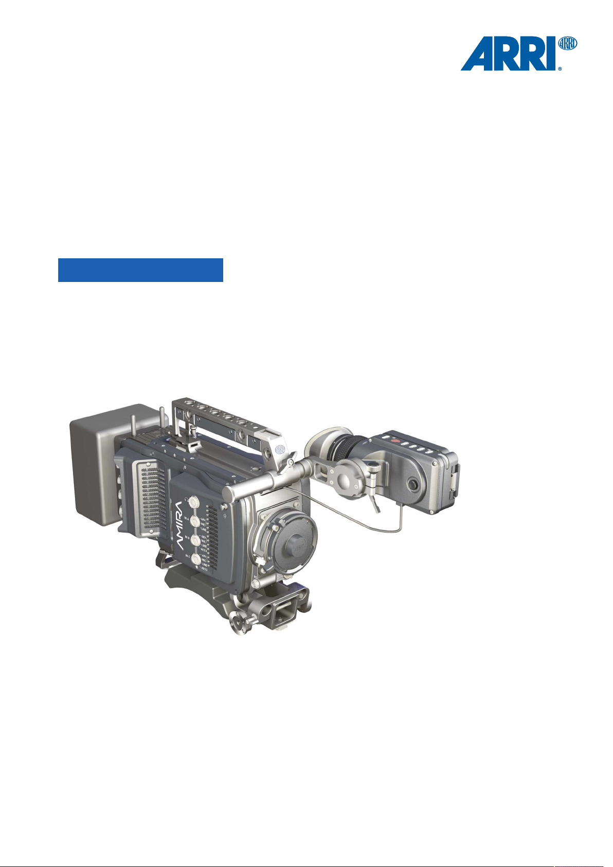
AMIRA
AMIRA
Software Update Packet 4.1
Software Update Packet 4.1
U S E R M A N U A L
U S E R M A N U A L
7 June 2016
7 June 2016
Page 2

2 Imprint
Imprint
Copyright
© 2016 Arnold & Richter Cine Technik GmbH & Co. Betriebs KG. All rights reserved.
No portions of this document may be reproduced without prior written consent of
Arnold & Richter Cine Technik GmbH & Co. Betriebs KG. Specifications are subject to
change without notice. Errors, omissions, and modifications excepted.
AMIRA, ALEXA, and ALEXA XT are trademarks or registered trademarks of Arnold
& Richter Cine Technik GmbH & Co. Betriebs KG. All other brands or products are
trademarks or registered trademarks of their respective holders and should be treated
as such.
Original version.
For further assistance
Arnold & Richter Cine Technik GmbH & Co. Betriebs KG
Tuerkenstr. 89
D-80799 Munich, Germany
E-mail: service@arri.com
www.arri.com/service
Document revision history
Version
1.0
1.1 10000464 K08658 19 Dec 2014
2.0 10000464 K08781 31 Mar 2015
3.0 10000464 K08941 02 Nov 2015
4.0 10000464 K09036 23 May 2016
4.1 10000464 K09090 7 June 2016
ID
10000464
Release
K08608
Date
12 Sep 2014
Page 3

Contents 3
Contents
1 For your safety /
1.1 Risk levels and alert symbols /
1.2 Vital precautions /
1.3 General precautions /
2 Audience and intended use............................................................... 12
3 Scope of delivery and warranty......................................................... 13
4 Camera layout......................................................................................14
4.1 Product identification........................................................................... 18
5 Power supply....................................................................................... 19
5.1 Changing a Gold Mount battery..........................................................19
5.2 Changing a V-Lock battery..................................................................20
5.3 BAT in.................................................................................................. 20
5.4 Powering auxiliary devices via camera............................................... 20
6 Switching on/off...................................................................................21
7 Connectors........................................................................................... 22
为了您的安全
重要安全措施
般安全措施
..............................................................8
危险级别和警示标志
........................................................... 9
....................................................... 10
.............................8
7.1 Front connectors..................................................................................22
7.2 Audio connector panel.........................................................................23
7.3 I/O panel.............................................................................................. 25
7.4 Media panel......................................................................................... 27
7.4.1 Preparing a USB memory stick...........................................................28
7.4.2 Changing a CFast 2.0 card.................................................................28
8 Lens mount/filters................................................................................30
8.1 ND filter switch.................................................................................... 30
8.2 Changing a lens.................................................................................. 31
8.3 Lens control......................................................................................... 32
8.3.1 Manual iris adjustment........................................................................ 32
8.3.2 Iris control via user button...................................................................33
8.3.3 Auto iris................................................................................................33
9 Audio control panel.............................................................................34
9.1 Channel configuration..........................................................................34
9.2 Headphone volume............................................................................. 36
10 Audio menu.......................................................................................... 37
10.1 AUDIO > INFO.................................................................................... 37
10.2 AUDIO > 1/2........................................................................................38
10.3 AUDIO > 3/4........................................................................................39
Page 4

4 Contents
10.4 AUDIO > SETUP.................................................................................40
10.4.1 Maximum line levels............................................................................41
10.4.2 Bluetooth..............................................................................................41
11 Camera Controls..................................................................................44
11.1 Operator panel.....................................................................................44
11.1.1 Operator switches................................................................................44
11.1.2 Setting the US switch function............................................................ 45
11.1.3 Presetting the US / EI / WB switches..................................................46
11.1.4 AW auto white balance button............................................................ 46
11.2 User preset panel................................................................................48
11.2.1 Locking/unlocking................................................................................ 48
11.2.2 User buttons........................................................................................ 48
11.3 Recording.............................................................................................49
12 MVF-1 controls.....................................................................................51
12.1 EVF image/monitor..............................................................................51
12.2 MVF-1 buttons..................................................................................... 53
12.2.1 PK peaking button...............................................................................53
12.2.2 EXP exposure tool button................................................................... 54
12.2.3 VF1 & VF2 user buttons..................................................................... 54
12.2.4 PLAY button.........................................................................................54
12.2.4.1 Playback screen controls........................................................................... 55
12.3 Diopter adjustment.............................................................................. 57
12.4 Adjusting the monitor...........................................................................57
12.5 Changing the monitor mode................................................................58
12.6 Live monitor......................................................................................... 59
12.7 User monitor........................................................................................ 60
12.8 Message popups................................................................................. 60
12.9 Adjusting the monitor brightness.........................................................61
13 Overlay menu.......................................................................................62
14 Web remote.......................................................................................... 64
15 CCP-1.................................................................................................... 66
16 Home screen........................................................................................ 68
16.1 Status section...................................................................................... 70
16.2 ALERT messages................................................................................72
16.3 Info screens......................................................................................... 72
16.4 FPS settings........................................................................................ 77
16.4.1 Setting/adding an FPS value...............................................................78
16.4.2 Deleting an FPS value........................................................................ 80
16.5 TC settings.......................................................................................... 81
Page 5

Contents 5
16.6 SHUTTER settings.............................................................................. 84
16.6.1 Selecting a SHUTTER unit..................................................................84
16.6.2 Setting/adding a SHUTTER value.......................................................86
16.6.3 Deleting a SHUTTER value................................................................ 88
16.7 WB settings......................................................................................... 90
16.7.1 Setting/adding a WB value..................................................................90
16.7.2 Renaming a WB value........................................................................ 92
16.7.3 Deleting a WB value........................................................................... 93
16.7.4 WB Options......................................................................................... 94
16.8 LOOK and gamma settings.................................................................95
16.8.1 Setting the LOOK file.......................................................................... 96
16.8.2 Setting Gamma....................................................................................97
16.8.3 Adding a LOOK file............................................................................. 98
16.8.4 Deleting a LOOK file......................................................................... 100
16.8.5 Exporting a LOOK file....................................................................... 102
16.8.6 Duplicating/renaming a LOOK file.....................................................103
16.8.7 LOOK parameters............................................................................. 104
16.8.7.1 ASC CDL Transforms.............................................................................. 105
16.8.7.2 3D LUT and video look parameters.........................................................105
16.8.7.3 Custom 3D LUT....................................................................................... 106
16.8.8 LOOK editing..................................................................................... 106
16.9 EI settings..........................................................................................109
16.9.1 EI technical details............................................................................ 110
17 Camera menu.....................................................................................112
18 MENU > Recording............................................................................113
18.1 Recording Codec...............................................................................113
18.2 Resolution.......................................................................................... 113
18.3 Project settings.................................................................................. 114
18.3.1 Project rate........................................................................................ 114
18.3.2 Next reel count.................................................................................. 115
18.3.3 Camera Index.................................................................................... 115
18.3.4 Camera ID prefix............................................................................... 115
18.4 Record mode..................................................................................... 115
18.5 Rec beeper / tally.............................................................................. 116
18.6 Pre-recording..................................................................................... 117
18.6.1 How to activate pre-recording........................................................... 117
18.6.2 Pre-recording maximum duration...................................................... 118
19 MENU > Media................................................................................... 120
19.1 Erase CARD A & B........................................................................... 120
19.2 Delete last clip CARD A & B.............................................................122
Page 6

6 Contents
19.3 Prepare USB medium....................................................................... 123
20 MENU > Monitoring........................................................................... 125
20.1 EVF/Monitor....................................................................................... 125
20.1.1 Surround view....................................................................................126
20.1.2 Zoom position.................................................................................... 126
20.1.3 Exposure tool.....................................................................................126
20.1.4 Peaking.............................................................................................. 128
20.1.5 Settings.............................................................................................. 128
20.1.6 EVF overlays / Monitor overlays / SDI overlays................................ 129
20.2 SDI..................................................................................................... 131
20.3 Frame lines........................................................................................134
20.3.1 Setting/adding a frame line............................................................... 134
20.3.2 Deleting a frame line......................................................................... 136
20.3.3 User rectangle 1 & 2......................................................................... 137
20.4 Return in path config......................................................................... 138
20.5 Color bars.......................................................................................... 138
21 MENU > System.................................................................................139
21.1 Sensor................................................................................................139
21.2 Fan mode.......................................................................................... 140
21.3 Power.................................................................................................141
21.4 System time + date........................................................................... 141
21.5 Buttons + display...............................................................................142
21.6 Multicam.............................................................................................144
21.7 Network / WiFi................................................................................... 145
21.8 Licensed features.............................................................................. 146
21.9 Camera update..................................................................................148
22 MENU > Setup....................................................................................149
23 MENU > User buttons....................................................................... 151
24 MENU > Metadata.............................................................................. 155
25 Camera preparation...........................................................................156
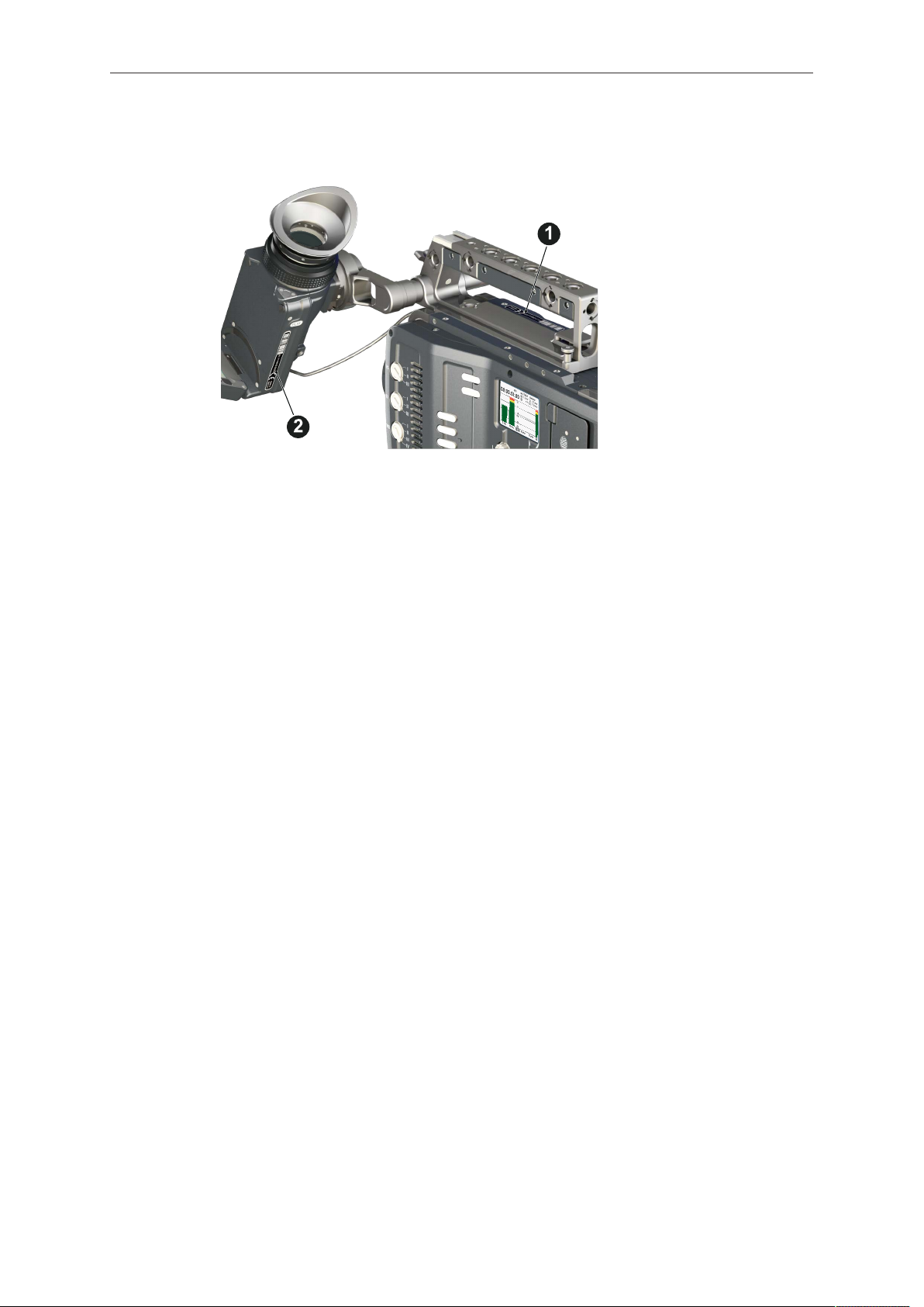
25.1 Adjusting the viewfinder.................................................................... 156
25.2 Balancing the camera weight............................................................ 157
25.3 Mounting to a wedge plate................................................................157
25.4 Mounting to a bridge plate................................................................ 158
26 Assembly and retrofits..................................................................... 159
26.1 Battery adapter.................................................................................. 159
26.2 Base adapter..................................................................................... 160
26.3 Camera handle.................................................................................. 162
Page 7

Contents 7
26.4 Viewfinder and EVF cable.................................................................162
26.5 Antennas............................................................................................165
26.6 Microphone bracket........................................................................... 166
26.7 Changing a lens mount..................................................................... 166
27 Licensing and updating.................................................................... 169
27.1 Camera update..................................................................................169
27.2 Licensing............................................................................................171
27.2.1 License bundles.................................................................................171
27.2.2 Extracting HW INFO from the camera.............................................. 173
27.2.3 Installing a license file....................................................................... 173
27.2.4 Downgrading to another license model/Deleting UHD license.......... 174
28 Appendix.............................................................................................176
28.1 Technical data....................................................................................176
28.2 Pin-outs..............................................................................................179
28.3 MPEG-2 Notice..................................................................................181
28.4 Declarations of conformity................................................................. 181
28.5 Dimensional drawings....................................................................... 182
29 ............................................................................................................. 186
Page 8
8 For your safety /
为了您的安全
1 For your safety /
Before use, please ensure that all users comprehensively read, understand, and
follow the instructions in this document. /
解,并遵循本文档内的操作说明。
为了您的安全
使用前,请确保所有的用户都已经阅读、理
1.1 Risk levels and alert symbols /
Safety warnings, safety alert symbols, and signal words in these instructions indicate
different risk levels:
DANGER!
DANGER indicates an imminent hazardous situation which, if not avoided, will
result in death or serious injury.
WARNING!
WARNING indicates a potentially hazardous situation which, if not avoided, may
result in death or serious injury.
危险级别和警示标志
CAUTION!
CAUTION indicates a potentially hazardous situation which, if not avoided, may
result in minor or moderate injury.
NOTICE
NOTICE explains practices not related to physical injury. No safety alert symbol
appears with this signal word.
Note: Provides additional information to clarify or simplify a procedure.
本文档内的安全警告、安全警示标志和标识词语指示不同的危险级别:
危险
危险表示危急、有危害的情景,若不防范,则会导致死亡或严重的伤害。
警告
警告表示有潜在危害的情景,若不防范,则可能会导致死亡或严重的伤害。
小心
小心表示有潜在危害的情景,若不防范,则可能会导致中等或较轻的伤害。
提示
注意表示此行为不会导致人身伤害。因此此标识词语中不含警告标志。
注:注意中会提供用于解释或简化工作的额外信息。
Page 9

For your safety /
为了您的安全
9
1.2 Vital precautions /
High voltage! Risk of electric shock and fire!
Short-circuits may entail lethal damage!
Before use, read and follow all valid instructions.
Use solely and exclusively as described in the instructions.
Never open. Never insert objects.
For operation, always use a power source as indicated in the instructions.
Always unplug the power cable by gripping the power plug, not the cable.
Never try to repair. All repair work should be done by a qualified ARRI Service
Center.
Never remove or deactivate any safety equipment (incl. warning stickers or paintmarked screws).
Always protect from moisture, cold, heat, dirt, vibration, shock, or aggressive
substances.
Never cover any fan openings.
高电压!有触电或起火风险!
短路将引起致命危险。
使用之前,请仔细阅读所有未过期的使用说明,并严格遵循。
切勿打开机身。切入插入任何物体。
操作时,请务必使用说明中指出的电源。
断开电源时请握住电源插头,而不是电线。
切勿尝试自行维修。所有的维修工作必须由具备资质的
切勿移除或毁坏任何安全设施(例如警告贴纸或涂漆标示的螺丝)。
务必避免潮湿、寒冷、炎热、多尘、震动、冲击或严酷的使用环境。
切勿覆盖任何风扇开口。
重要安全措施
DANGER!
危险
ARRI
维修中心进行。
Page 10
10 For your safety /
CAUTION!
Condensation! Risk of electric shock and fire!
Condensation may form on the sensor and electrical connections when exposing
the camera to sudden changes of temperature or humidity!
To avoid injury and damage, never operate the camera when condensation occurs.
小心
冷凝!有触电或火灾风险!
当将摄影机暴露于温度或湿度迅速变化的环境中时,影像传感器和电子部件连接处可
能会产 为了您的安全
为了避免受伤或设备损坏,在冷凝发生时切勿操作摄影机。
6
生的冷凝。
CAUTION!
Heavy weight! Risk of injury and damage!
If placed on an unstable surface, the camera can fall and cause serious harm!
Always place the camera on proper support devices. Safely attach it as described
in the instructions.
为了您的安全
设备重量较大!有受伤或设备损坏风险!
若安置于不稳定的位置,则摄影机可能会掉落,并造成严重的伤害。
务必将摄影机安装于适当的支撑设备上。请按照说明中所描述的方法来安全地安装摄
影机。
1.3 General precautions /
Even rugged cameras use components sensitive to improper use.
Always unplug the camera from power sources before making changes to the setup
or system (in particular: changing cables).
Direct sunlight can result in camera housing temperatures above 60 °C (140 °F). At
ambient temperatures above 25 °C (77 °F), protect the camera from direct sunlight.
Protect the optical system and sensor: Never point the camera or viewfinder into
direct sunlight.
Avoid permanent sensor damage: Never let any direct light or reflections from highenergy light sources (e.g. laser beams) enter the camera's optical path.
Protect the sensor: Always keep a lens or protective cap on the empty lens mount.
Change lenses in dry, dust-free environments only.
Always clean the sensor cover glass according to ARRI instructions.
Only use the tools, materials and procedures recommended in this document. For
the correct use of other equipment, see the manufacturer's instructions.
小心
般安全措施
NOTICE
Page 11

For your safety /
为了您的安全
提示
即使本摄影机非常坚固,也是由敏感的组件所组成的,请谨慎使用。
当改变摄影机安装支撑设备或系统时(特别是更换电缆),请务必断开摄影机电源。
注意保护光学系统和影像传感器:切勿将摄影机或取景器直接面朝直射阳光。
避免对影像传感器造成永久性伤害:切勿让任何来自高能量光源(例如激光)的直射
光或反 射光进入摄影机的光路系统。
注意保护影像影像传感器:空镜头卡口上务必安装镜头或保护盖。更换镜头时,务必
在干燥、 无尘的环境中进行。
请完全并仅按照用户手册中所描述的方法来清洁影像传感器保护玻璃。若清洁不成
功,请咨 询
清洁影像传感器保护玻璃时,务必遵守
仅使用本文档中建议使用的工具、材料和操作方法。若要正确地使用其他设备,请参
阅其制 造商的说明书。
ARRI
维修中心。切勿尝试打开保护玻璃。
ARRI
说明书中描述的方法。
11
Page 12

12 Audience and intended use
2 Audience and intended use
NOTICE
The product is solely and exclusively available for commercial costumers and shall
be used by skilled personnel only. Every user should be trained according to ARRI
guidelines.
Use the product only for the purpose described in this document. Always follow the
valid instructions and system requirements for all equipment involved.
The AMIRA is a 35 mm digital camera solely and exclusively for recording HD 1080,
2K, 3.2K* or 4K UHD* images suitable for a variety of distribution formats:
ProRes 422 LT, ProRes 422, ProRes 422 HQ*, ProRes 4444*, ProRes 4444
•
XQ*, MPEG-2 HD 422* codecs
REC 709 encoding (through use of look files) or Log C* encoding
•
CFast 2.0 card recording
•
Up to 200 fps* in HD/2K with full image quality
•
35 mm CMOS sensor
•
EVF with OLED eyepiece
•
Fold-away monitor for both live view and user interface access
•
Ready out-of-the-box for single-user-centric workflow
•
Slim, ruggedly built for high mobility
•
* Feature requires licensing.
Page 13

Scope of delivery and warranty 13
3 Scope of delivery and warranty
NOTICE
Product and packaging contain recyclable materials. Always store, ship, and
dispose of according to local regulations.
ARRI is not liable for consequences from inadequate storage, shipment or disposal.
Delivery
On delivery, please check if package and content are intact. Never accept a damaged/
incomplete delivery. A complete delivery includes:
AMIRA camera with lens mount according to order: PL, EF, B4
•
Multi-viewfinder with AMIRA EVF cable
•
Gold Mount or V-Lock battery adapter (if ordered)
•
Camera handle with viewfinder adapter
•
Four XLR connector caps (one spare; keep all four for later use!)
•
Four BNC connector caps (remove before use)
•
WPA-1 or BPA-3 base adapter (if ordered)
•
WiFi antenna
•
Bluetooth antenna
•
USB memory stick
•
3 mm Allen key
•
Quick Guide
•
Original packaging incl. drying agent
•
Usually, the camera comes fully assembled. In the unlikely case that a handle,
viewfinder, adapter, or antenna (etc.) is not assembled, see page 159 for
instructions.
NOTICE
ARRI offers an increasing variety of product bundles and additional accessories.
For details, please consult our website or your local ARRI Service Partner.
Warranty
For scope of warranty, please ask your local ARRI Service Partner. ARRI is not liable
for consequences from inadequate shipment, improper use, or third-party products.
Page 14
14 Camera layout
1
2
3
4
5
6
7
8
9
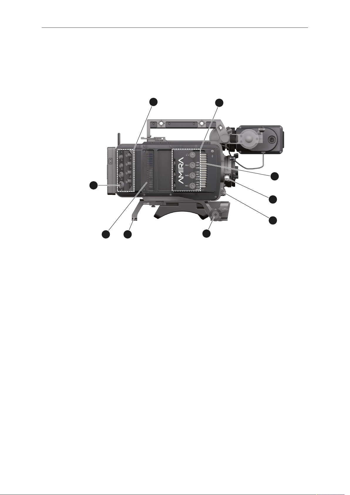
4 Camera layout
Right
1 BAT power input 6 RS connector
2 I/O panel 7 Bracket rosette
3 Audio connector panel 8 WPA-1 with quick release connectors
4 Fan intake 9 Fan outlet
5 12-pin Hirose for ENG type lenses
Page 15

Camera layout 15
1
2
3
4
5
6
7
8
9
10
Left
1 Operator panel 6 Media panel (behind lid)
2 User buttons 7 Battery adapter
3 Power button & camera lock 8 Fan intake
4 Audio control panel 9 Recording button
5 Lid 10 Bracket rosette
Page 16
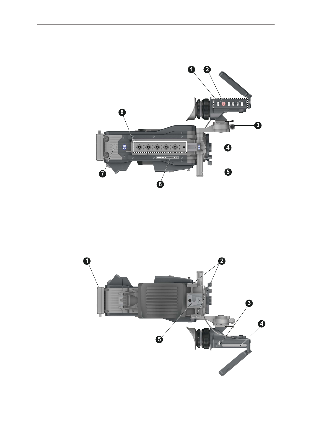
16 Camera layout
Top
1 Viewfinder top buttons 5 Adjustable beam
2 Recording button 6 Camera type label
3 Viewfinder hinge with clamp 7 Level
4 Accessory shoe 8 Accessory threads on camera handle
Bottom
1 Battery adapter 4 Viewfinder type label
2 Bracket rosettes 5 WPA-1 quick-lock bracket
3 PLAY button
Page 17
Camera layout 17
Front
1 Clamps 4 15 mm rod receptacles
2 Lens mount (here: PL) 5 RS connector
3 ND filter switch
Back
1 Fold-away monitor (viewfinder/GUI) 5 I/O panel
2 OLED eyepiece 6 BAT power input
3 Bluetooth antenna 7 Battery adapter (here: Gold Mount)
4 WiFi antenna 8 Proximity sensor for OLED eyepiece
Page 18
18 Camera layout
4.1 Product identification
CE type labels with serial number are on the camera top (1) and under the viewfinder
(2). The serial number consists of the last 5 digits of the equipment number
K1.71700.0-XXXXX. An FCC conformity label is on the camera bottom.
Page 19
Power supply 19
5 Power supply
Depending on your battery demand, the camera offers either a Gold Mount or a VLock adapter. You can change both by yourself (see page 159). For further details,
see our website or ask your local ARRI Service Partner.
NOTICE
For maximum operation time, always use fully charged batteries with 10.5 to 34 V
DC (50 W minimum).
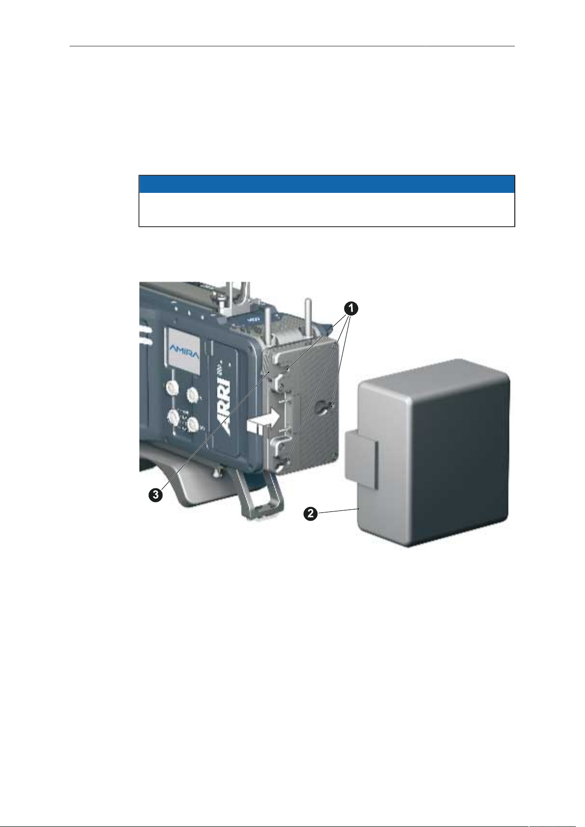
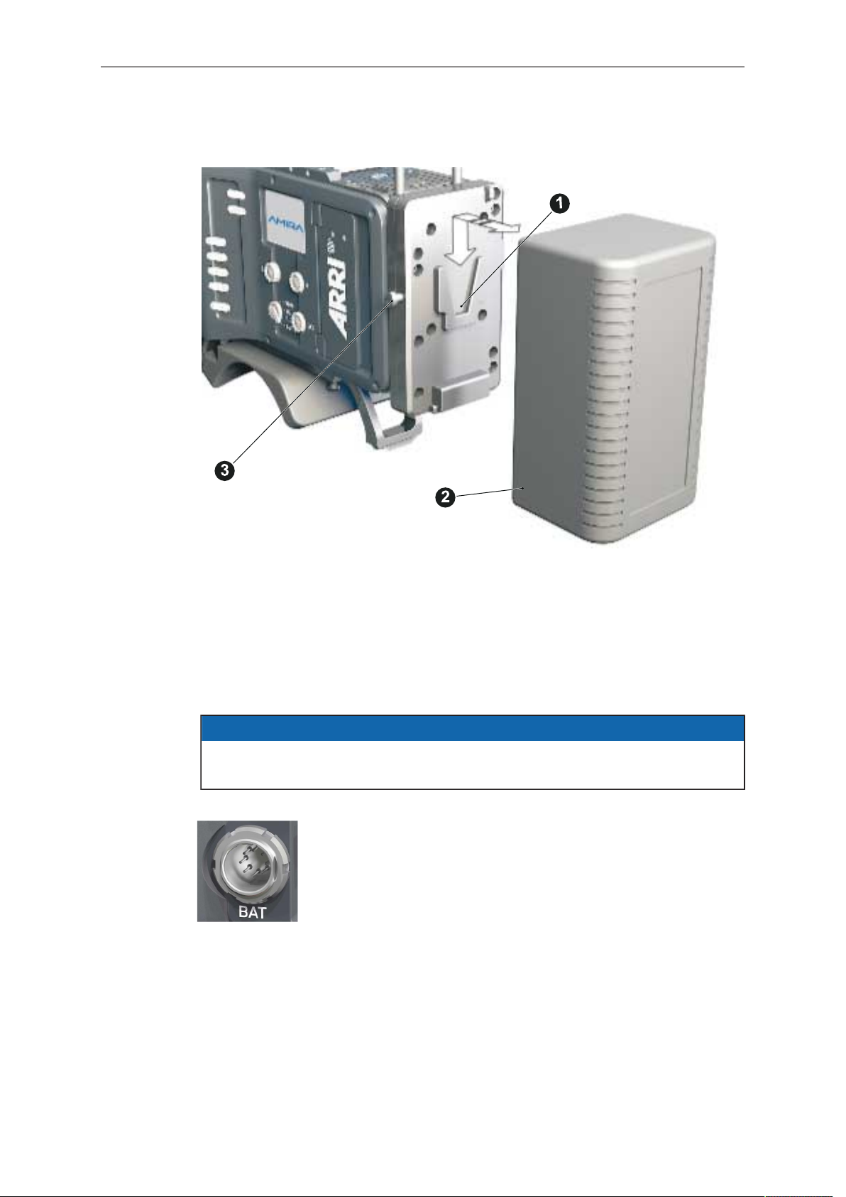
5.1 Changing a Gold Mount battery
1. Place the battery pins in the mount receptors (1).
2. Slide the battery (2) to the right until the adapter audibly locks (1).
3. To release: With the lever pushed (3), slide the battery (2) to the left and
backwards.
Page 20
20 Power supply
5.2 Changing a V-Lock battery
1. Place the battery's wedge into the V-shaped lock (1).
2. Slide the battery (2) downwards until the adapter audibly locks (1).
3. To release: With the pin pushed (3), slide the battery (2) up- and backwards.
5.3 BAT in
NOTICE
If the power supply to BAT is interrupted with the camera switched on, the camera
will automatically repower and boot-up on reconnection.
Use the BAT connector, and a KC50-S or KC50-SP-S cable, to
supply the camera with 10.5 to 34 V DC.
5.4 Powering auxiliary devices via camera
You can supply auxiliary devices from the camera via several connectors (2.0 A max):
12 V via 2-pin LEMO, 4-pin Hirose, or via D-tap on battery adapter
•
24 V via RS
•
Camera voltage via EXT
•
Note: For connector pin-out information, see appendix. With a critical power supply
level, the camera switches off all auxiliary power supplies first.
Page 21
Switching on/off 21
6 Switching on/off
1. To switch on: Press the power button (1).
2. The ARRI and AMIRA logos appear in the audio display (2) and monitor (3).
3. To switch off: Press and hold the power button (1).
4. A countdown appears in the audio display, monitor, and viewfinder.
5. On reaching zero, the camera powers off.
6. Note: The STBY icon (1) signals that the camera is ready to record.
7. If not: Insert a CFast 2.0 card. See page 156.
8. Format the card for recording.
Page 22
22 Connectors
7 Connectors
NOTICE
Connecting or disconnecting devices or cables while recording can disturb the
audio/image signal due to static electricity.
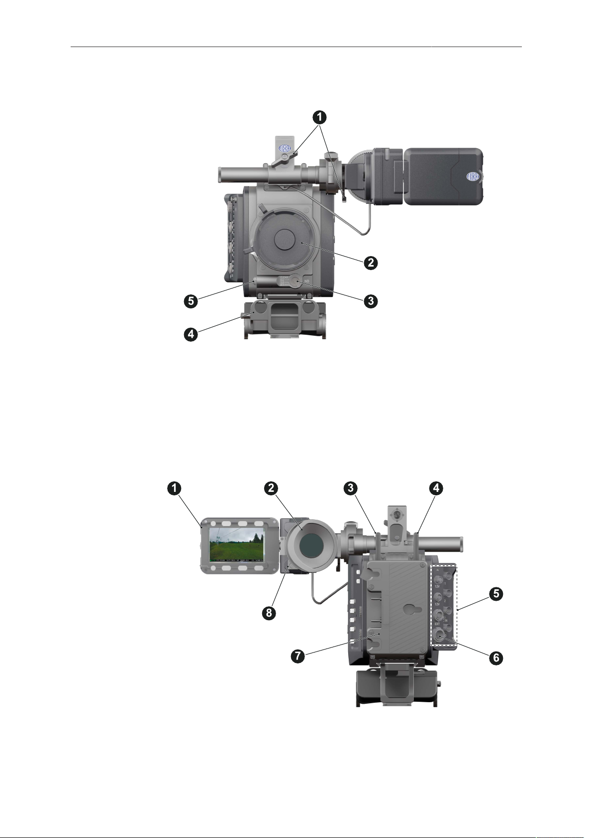
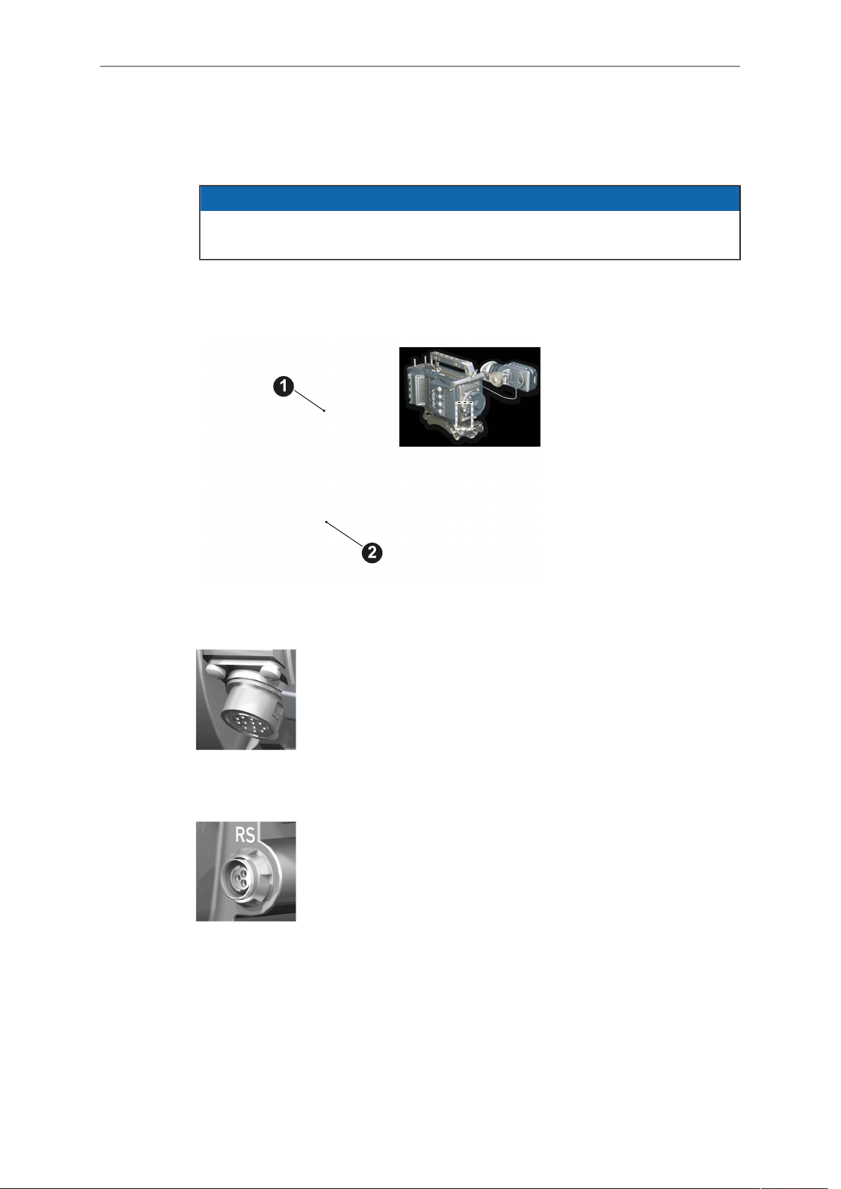
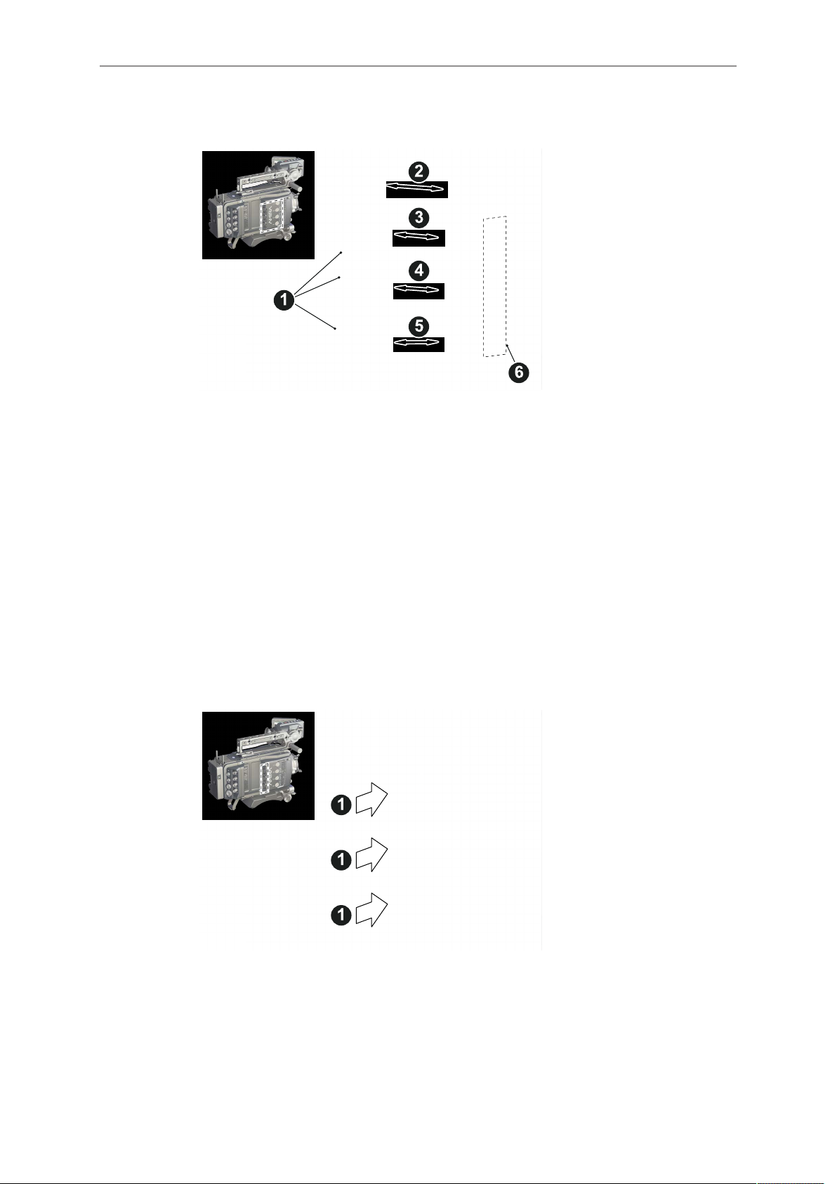
7.1 Front connectors
1 12-pin Hirose for ENG type
lenses
2 3-pin Fischer RS
ENG (12-pin Hirose)
Supplies lens servos with power and provides access to lens servo functions.
RS (3-pin Fischer)
This 3-pin Fischer socket for RS input supplies external accessories with 24 V power (2.0 A). It also carries a frame pulse output and accepts an ARRI remote start/stop trigger.
Page 23
Connectors 23
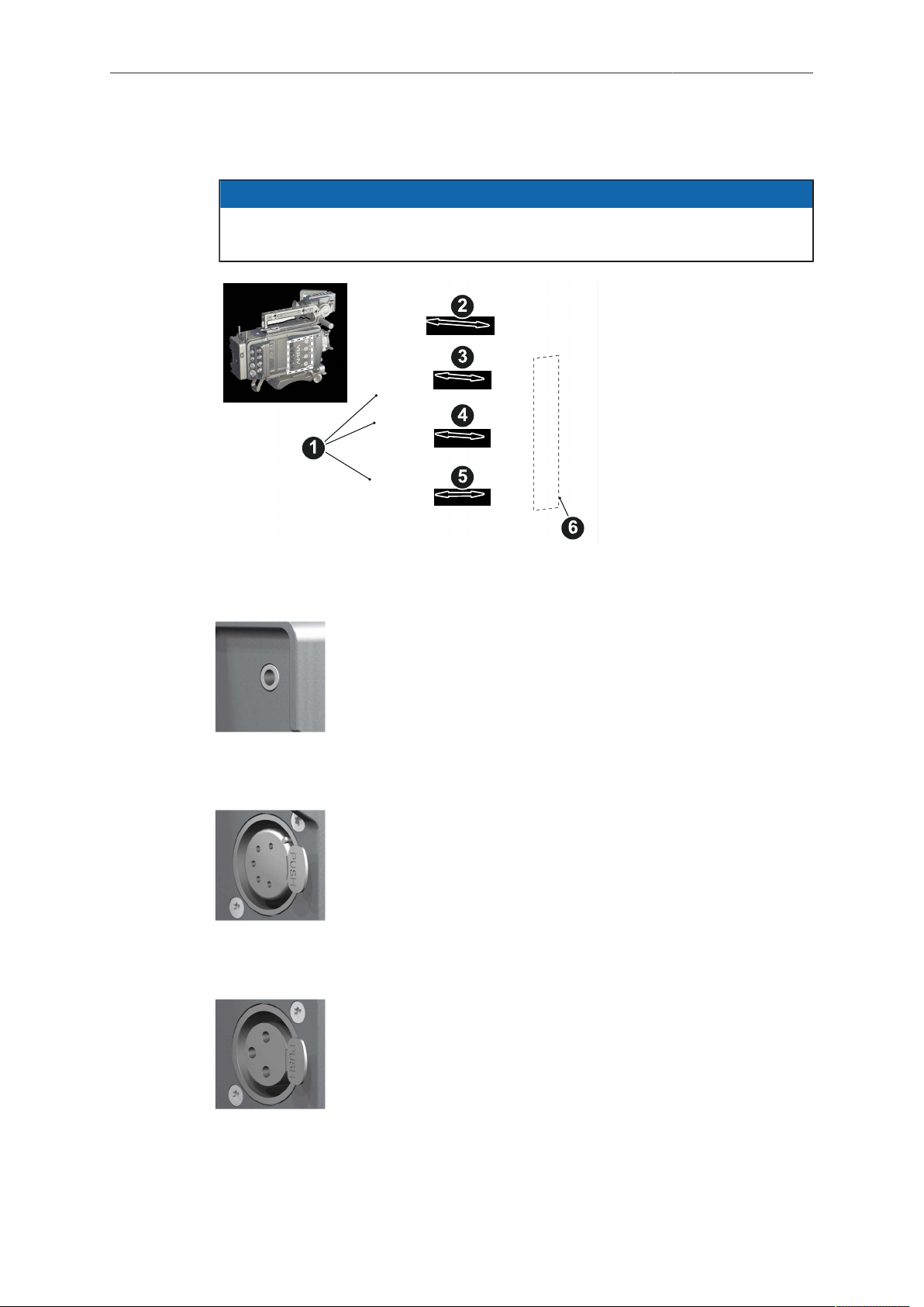
7.2 Audio connector panel
NOTICE
Rubber caps protect the XLR connectors from dirt and moisture. Always cap
unused XLR connectors.
1 Protective caps
2 Headphone out & volume
3 XLR 5-pin audio input
4-5 XLR 3-pin audio input
6 Input signal options
Headphone
Headphone 3.5mm stereo TRS (“Mini-jack”) output for monitoring
audio channels.
IN A (5-pin XLR)
XLR input for microphone signals (including 48V phantom power
supply) and line level signals.
IN B & C (3-pin XLR)
XLR input for microphone signals (including 48V phantom power
supply), line level signals and AES3 digital.
Page 24
24 Connectors
Connecting audio devices
1. Uncap the needed connectors only (1).
2. Connect the headphone (2).
3. Set the headphone volume by turning the wheel (2).
4. Alternatively, you can use the SET wheel on the camera's left. See page 36.
5. Via switches (3 to 5), select the appropriate setting for your audio device (6):
48V: Analog microphone level signals with phantom power supply
°
MIC: Analog microphone level signals
°
LINE: Analog line level signals
°
AES3: Digital AES/EBU signals
°
6. Connect each device (3 to 5) until the connector audibly locks.
Disconnecting audio devices
1. Press the PUSH button to unlock (1).
2. Remove the cable by pulling on the connector.
3. Replace with another cable.
4. Or: Cap the connector for protection.
Page 25
Connectors 25
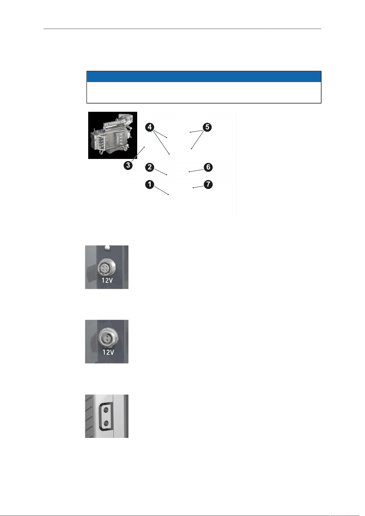
7.3 I/O panel
NOTICE
If the power supply to BAT is interrupted with the camera switched on, the camera
will automatically repower and boot-up on reconnection.
1 BAT main power in
2 EXT in/out
3 D-tap
4 Aux power out
5 HD-SDI image out 1 & 2
6 Return/sync in
7 Timecode in/out
12V (4-pin Hirose)
Supplies 12 V auxiliary power with a maximum power of 2.0 A
(combined with the 2-pin LEMO).
12V (2-pin LEMO)
Supplies 12 V auxiliary power with a maximum power of 2.0 A
(combined with the 4-pin Hirose).
D-tap
A D-tap on the battery adapter supplies accessories with 12 V
DC from the camera.
Page 26
26 Connectors
EXT (6-pin LEMO)
A connector for external accessories, carrying two CAN buses and accessory power output at camera voltage level (2.0 A
max.).
BAT (8-pin LEMO)
Via cables KC50-S (2 m, straight) and KC50-SP-S (coiled), this
main power supply input accepts 10.5 to 34 V DC.
SDI OUT 1 & 2 (BNC)
Both BNC sockets (here: SDI 1) deliver image outputs in
1920x1080 422 1.5G, 422 3G and 444 3G single link formats.
SDI 2 also supports the 3840x2160 422 6G format in 4K UHD
mode.
RET/SYNC IN (BNC)
A BNC socket for Genlock input, or HD-SDI return image signal
(configurable). Supports Black Burst, Tri-Level Sync and HD-SDI
genlock signals.
You can feed HD-SDI return signals from another image source
to the camera RET connector. The signal must be a 1920x1080
422 1.5G SL according to SMPTE 274M and 292M. Via the camera menu, you can set the output routing of the RET in signal.
TC I/O (BNC)
A Timecode in-/output (BNC interface) to be configured via camera menu.
For external TC feeds to the camera.
•
Note: Always use Genlock together with Timecode to prevent TC drifts. If Black Burst or Tri-level sync signals are not
available, the camera can be configured to use the TC signal
itself as Genlock.
Note:The camera has a TC buffer to keep a synced free run
TC for up to 10 minutes while camera power is disconnected.
For camera TC feeds to other devices.
•
Page 27
Connectors 27
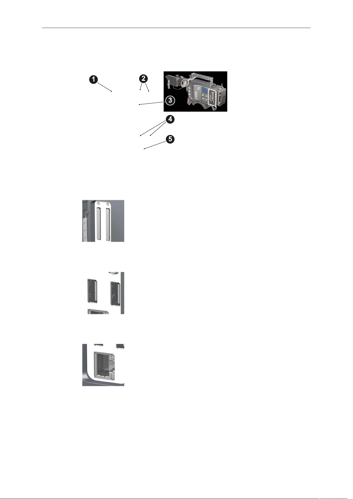
7.4 Media panel
1 Lid
2 Status LEDs
3 CFast 2.0 card slots A & B
4 USB in/out 1 & 2
5 RJ45 Ethernet
Card A & B (CFast 2.0)
USB 1 & 2
Ethernet LAN
Storage media slots for CFast 2.0 recording cards.
Interface for USB memory sticks with FAT file system. Can also
be used to charge USB devices. Each port supplies 5V with a
maximum current of 500mA.
Note: Only one USB memory stick can be used at a time. Independent from slot, the stick connected first becomes active.
Meanwhile, the second slot can still be used to charge a device.
This RJ45 remote and service interface works via LAN.
Page 28
28 Connectors
7.4.1 Preparing a USB memory stick
USB memory sticks for the AMIRA must have a specific folder structure which can be
created with the camera.
1. To prepare a USB memory stick: Open the media lid (1).
2. Connect a FAT-formatted USB stick (3) to the camera (2).
3. Note: To avoid file corruption, never remove the USB stick during write access.
4. Via jogwheel, open MENU > Media > Prepare USB medium.
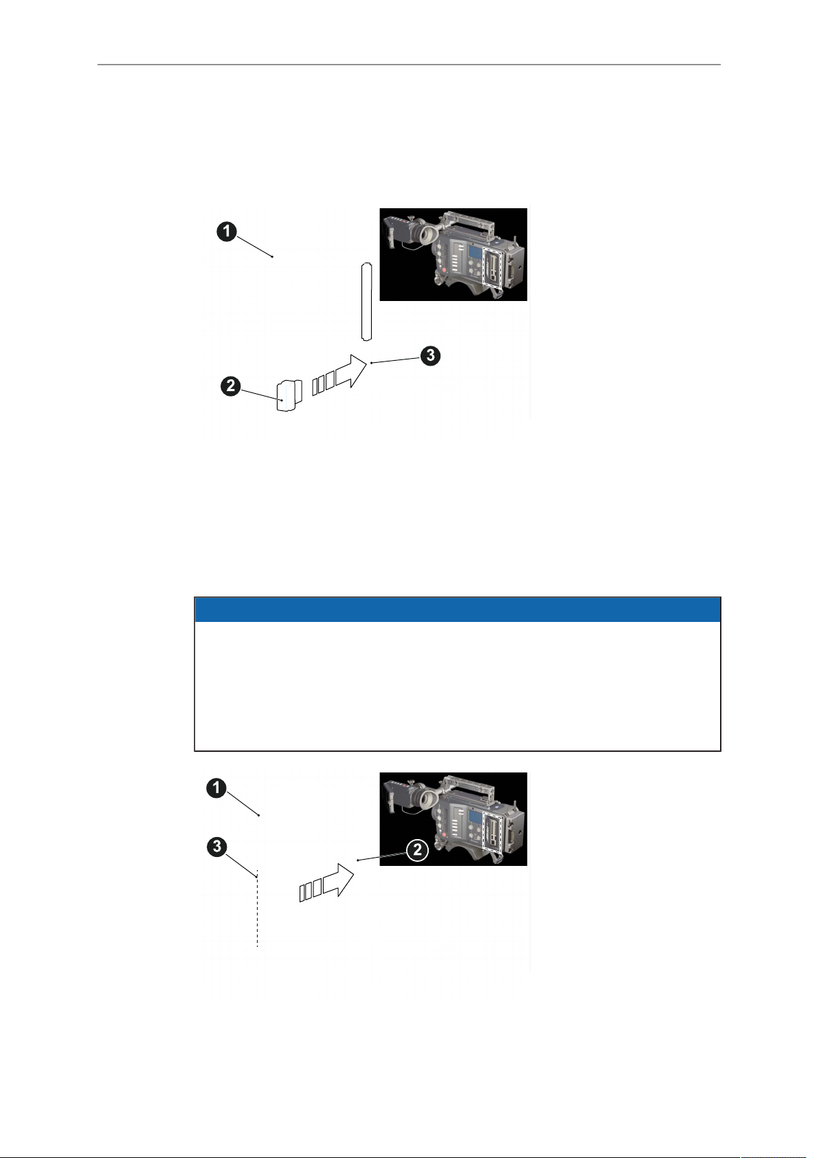
7.4.2 Changing a CFast 2.0 card
AMIRA does not accept ALEXA-formatted CFAST 2.0 cards, and vice versa.
Before using a CFAST 2.0 card with AMIRA, you must erase it in-camera to create
the required file system.
Avoid damage to the contacts of both camera and card. Always insert cards as
described in this document.
Never change memory cards when recording - this may damage the recorded clip.
NOTICE
1. Open the lid (1).
2. Align the card's positive edge (3) facing the camera rear.
3. With the contact pins first, gently insert the card, until it audibly locks (2).
Page 29

Connectors 29
4. Gently close the lid (1). Never force it closed on an unlocked card.
5. To quickly change the active card you can set up a user button. See page 49.
6. For card removal: Open the lid (1).
7. Push the card in until it audibly unlocks (2).
8. Remove the card.
Page 30
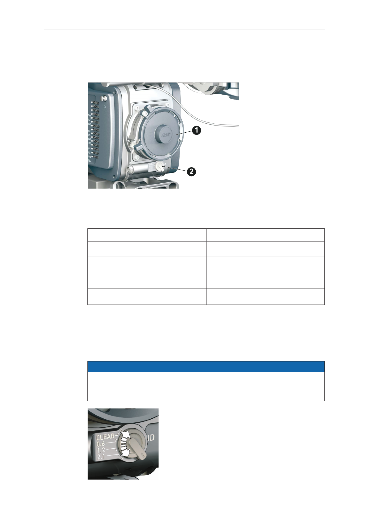
30 Lens mount/filters
8 Lens mount/filters
1 Lens mount (here: PL)
2 ND filter switch (clear - 0.6
- 1.2 - 2.1)
Cooke /i support
The camera supports the Cooke /i protocol for lenses running FW versions according
to the following table.
Lens type FW version
S4 /i Prime lens (10-bit) 0.29 or higher
S4 /i Prime lens (12 bit) 0.39 or higher
S4 /i Zoom lens (10 bit) 1.29 or higher
S4 /i Zoom lens (12 bit) 1.39 or higher
The FW version can be retrieved from the lens with the Cooke Viewer Lens Display
program. For detailed info, please contact Cooke Optics directly.
8.1 ND filter switch
AMIRA uses FSND (Full Spectrum Neutral Density) filters, which are linear across
the full spectrum of the camera sensor. This prevents artifacts from infrared
wavelengths and the need for additional IR filters.
NOTICE
The ND filter switch controls the internal ND filter module.
Filter densities of 0.6, 1.2 and 2.1 allow quick exposure
changes and compensation over a range of seven stops.
1. To activate a filter: Switch to the desired filter position.
Page 31

Lens mount/filters 31
Other ways to control ND filter
The ND filter can also be controlled via user buttons, the web remote or the overlay
menu, accessible via HOME>EI>ND. Any of these may result in the active ND filter not
matching the ND switch position.
A difference between current switch position and active ND filter is indicated by an
orange ND value on the homescreen and in the status overlays of monitor, EVF and
SDI images (if overlays are active). The currently selected ND filter is also stored in
and recalled from user setup files.
To give precedence to the ND filter switch, change the switch position once.
8.2 Changing a lens
NOTICE
Protect the sensor: Always keep a lens or protective cap on the empty lens mount.
Change lenses in dry, dust-free environments only.
Never exceed the maximum lens dimensions.
Have every lens properly shimmed as prescribed by the manufacturer.
PL mount
1. Observe maximum lens dimensions.
2. Unlock the lens mount counter-clockwise (1) and remove the lens or cap.
3. Never touch the sensor.
4. Either: Mount the next lens and lock (2) the lens mount clockwise.
5. Or: Always cap and lock (2) an empty lens mount clockwise.
EF mount
Page 32

32 Lens mount/filters
1
2
Note: Please use a lens support system for EF lenses above 2 kg/4.4 lbs.
1. Observe maximum lens dimensions.
2. Turn the lever counter-clockwise (1) to unlock the mount.
3. Either: Unscrew the cap.
4. Or: Press and hold the button (2) to unlock the lens.
5. Counter-clockwise, unscrew the lens (3).
6. Never touch the sensor.
7. Either: Mount the next lens:
Align the dots of both lens and lens mount.
°
Push the lens into the mount.
°
Turn the lens clockwise (5) until the bayonet locks.
°
Turn the lever clockwise (4) to tighten the lens to the lens mount.
°
8. Or: Always cap the empty lens mount.
8.3 Lens control
Control of lens iris is possible with ENG PL mount and EF lenses. You can control the
iris manually, via user button, or via auto iris.
8.3.1 Manual iris adjustment
HOME > EI > IRIS
Pressing the wheel (1) changes the step size between full and sub-stops (2). Note:
Sub-stop precision depends on the lens type and is automatically set by the camera.
Page 33

Lens mount/filters 33
1
2
1
On the live screen, you can activate and deactivate iris adjustment (1) by shortpressing the lower round button (2). Keeping the button pressed (2) activates iris
adjustment until it is released. (2). Note: Depending on the image flip, the round
buttons may appear on the right.
8.3.2 Iris control via user button
MENU > User button > Button X
For iris control, assign one user button each with Open Iris and Close Iris. See
page 151.
8.3.3 Auto iris
HOME > EI > IRIS > OPTIONS
Via jogwheel (1), you can define the auto iris behavior.
Auto iris mode: Defines the iris calculation:
Integral: Iris is calculated based on full image content.
•
Center: Iris is calculated with higher priority on image center.
•
Auto iris offset: Corrects the auto iris calculation result by up to +/- 3 stops in 1/3 stop
step sizes. Activate via user button.
Page 34

34 Audio control panel
9 Audio control panel
1 Audio function switch
2 Audio display
3 Left/right gain controls
4 Audio SET jogwheel
9.1 Channel configuration
Audio is disabled if the sensor frame and project rates are not equal. With audio
recording disabled or otherwise switched off, neither audio in/output nor audio
processing is possible.
Checking the audio status
NOTICE
1. Select INFO (1) to display current status information (2).
2. L and R (3) are now deactivated.
3. Turning the depressed SET jogwheel (4) will change the headphone volume.
Page 35

Audio control panel 35
1
2
3
Adjusting channel gain
1. Select 1/2 or 3/4 (1).
2. Adjust channel 1 (or 3) gain via left gain control (2).
3. Adjust channel 2 (or 4) gain via right gain control (2).
4. To change channel 1/2 (or 3/4) setup: Select the desired parameter via SET
jogwheel (3).
5. To enter the edit mode: Press SET (3).
6. To change a parameter: Turn the SET jogwheel (3).
7. To confirm and leave the edit mode: Press SET (3) again.
Editing the audio setup
1. Select SETUP (1) for adjusting overall audio parameters (2).
2. To navigate and adjust: Press and turn the SET jogwheel (3).
3. To enter or confirm: Press SET (3).
4. Select the desired parameter via SET jogwheel (3).
5. To enter the edit mode: Press SET (3).
6. To change a parameter: Turn the SET jogwheel (3).
7. To confirm the value: Press SET (3) again.
Page 36

36 Audio control panel
9.2 Headphone volume
Use the headphone volume wheel (see above).
Or: Use the audio control panel (see below):
1. Switch to INFO (1).
2. The volume level shows next to the headphone icon in the display.
3. Turn the depressed SET jogwheel (2).
Page 37

Audio menu 37
10 Audio menu
On the audio control panel, you can fully control, change, and edit the audio setup
without the risk of accidentally changing camera parameter.
The audio function switch
(1) toggles between INFO
screen, channel 1/2 and 3/4
configurations, and audio
SETUP on the display (2).
The L and R jogwheels (3)
control left and right channel
gain.
With the SET jogwheel (4),
you navigate through the
audio setup menu.
Note: For line level input, the camera supports a maximum analog input level of +8
dBu by default. Higher levels will result in clipping. Cameras with the new audio board
(IOAU2) have the option to select between +8 and +24 dBu as maximum input level.
Note: Additional audio meters are available on the camera monitor (fixed) and on the
EVF display (configurable via MENU > Monitoring > EVF/Monitor > EVF overlays >
Status elements > Audio).
10.1 AUDIO > INFO
1. Turn the audio function switch to INFO (1).
2. Note: The INFO position locks the left and right gain controls.
3. The audio INFO screen opens:
Page 38

38 Audio menu
1 Camera status
2 ALERT (!) status
3 Headphone volume level
4 BAT 1 & 2 power status
5 CARD A & B remaining
time or status
6 BT level
7 CHANNEL 3 & 4 input
mapping and levels
8 dB FS scale
9 CHANNEL 1 & 2 input
mapping and levels
10 TC Timecode
11 Clipping indicator
INFO shows the audio levels, the input channel mapping, and the most important
camera parameters:
Camera status (1): STBY (ready for recording). REC (recording). PLAY
•
(playback). None (card missing, full or not yet formatted).
The alert (!) icon appears (2) whenever alert messages are available. See
•
page 72.
Headphone volume (3) from level 1 (= off) to 64 (= maximum).
•
Power status (4): BATTERY 1 (onboard). BATTERY 2 (BAT IN). Can be set to
•
percent or volt, depending on battery. See page 141.
Remaining card capacities (5), in minutes.
•
Audio levels (7 and 9) for all four channels and BT (6), in dB FS.
•
Reference scale (8) for audio levels in dB FS.
•
Current timecode (10). TC settings are accessible via user monitor. See
•
page 83.
Clipping indicator (11): If the channel shows a red frame, the audio signal is
•
clipping. If the audio meter is not at its peak, the input signal itself is clipping.
10.2 AUDIO > 1/2
1. Turn the audio switch to 1/2 (1).
2. The left gain control (2) now addresses recording channel one. For channel two,
use the right gain control (3).
Page 39

Audio menu 39
3. Select and change parameters with the SET jogwheel (4).
4. The audio 1/2 screen allows you to configure gain control mode, filtering,
headphone monitoring, and input selection for channel one and two:
1 Cursor (here: on channel
one)
2 CTL: Gain control mode per
channel
3 Highpass filter per channel
4 MON: Headphone
monitoring per channel
5 IN: Input selection
Cursor (1): Can be moved by turning the SET jogwheel.
•
Gain control mode (2): MAN (manual via L/R wheels, in 1-dB steps). MAN + L
•
(manual plus limiter, in 1-dB steps).
A limiter prevents the signal from clipping if the input signal level combined
°
with the set gain results in signal levels exceeding -6 dB FS.
Highpass filter (3): Frequencies below the set value are filtered from the signal.
•
Off (no filtering), 80 Hz, or 160 Hz.
MON (4) routing of audio channel to headphones: L (to left headphone channel
•
only). R (to right headphone channel only). L+R (mono mix on both). Off (no
routing).
IN: Input source mapping to the respective recording channel. Available
•
channels depend on the XLR input configuration. Setting e.g. IN B to LINE
enables B Line. As IN A is a stereo input, A1 and A2 are also available. Setting
IN B or IN C to AES provides AES1 and AES2.
10.3 AUDIO > 3/4
1. Turn the audio funtion switch to 3/4 (1).
2. The left gain control (2) now addresses recording channel three. For channel four,
use the right gain control (3).
Page 40

40 Audio menu
3. Select and change parameters with the SET jogwheel (4).
4. The configuration of channels three and four is identical to that of channel one and
two above.
1 Cursor (here: on channel
three)
2 CTL: Gain control mode per
channel
3 Highpass filter per channel
4 MON: Headphone
monitoring per channel
5 IN: Input mapping
10.4 AUDIO > SETUP
1. Turn the audio function switch to SETUP (1).
2. By turning and pressing the SET jogwheel (2), you can now adjust basic settings
on the following screen:
Audio recording: Switches audio recording on or off. Off deactivates audio inputs and
all outputs; no audio channels are recorded.
Test tone: Activates a 1 kHz test tone on all recording channels.
Maximum line levels: Switches the maximum line level for input A, B and C.
Display brightness: Sets the audio display backlight from level 1 (= minimum) to 10 (=
maximum).
Display style: Sets both audio display and camera monitor to day or night style.
Page 41

Audio menu 41
Bluetooth: Allows you to monitor audio recording or to record talk-back tracks via
Bluetooth headphones or headsets.
10.4.1 Maximum line levels
Audio > Setup > Maximum line levels
Switches the maximum line level for input A, B and C between +8 and +24 dBu.
Note: Requires a camera hardware modification (new audio board IOAU2). After
changing maximum line levels, please check input gain settings.
10.4.2 Bluetooth
Audio > Setup > Bluetooth
Allows you to monitor audio recording with a Bluetooth headset. Monitors the same
channel configuration as the headphone out. Also allows you to record a talk-back
track (e.g., for work instructions, comments etc.).
Power: Switches Bluetooth on or off
•
Device list: Shows the available Bluetooth devices
•
Profile: Sets the Bluetooth connection profile
•
Page 42

42 Audio menu
HFP is required for talk-back function
°
A2DP has a higher audio signal quality
°
Note: Selected profile must be supported by Bluetooth headset. A2DP
°
mode may, depending on the device, cause a delay of up to 5 frames. With
HFP, audio is only available on right channel (R).
Talk back channel: Sets the talk-back channel to Open (signal is recorded) or
•
Muted (signal is not recorded). Can also be assigned to a user button
Talk-back monitoring: Configures the monitoring of the recorded talk-back
•
channel to the headphones out. Configuration is also valid during playback.
Can be set to Off, L (left out), R (right out), L+R (left and right out).
Connecting to a Bluetooth device
1. Open the Bluetooth menu.
2. Set Power to On.
3. Set the desired profile.
4. Via SET jogwheel, navigate to the device list:
Audio > Setup > Bluetooth > Device list
5. Ensure the Bluetooth device is active and visible.
6. Select the desired Bluetooth device from the list.
7. Press the SET jogwheel for connection.
Page 43

Audio menu 43
8. To disconnect: Select Disconnect <device name> and press the SET jogwheel.
Page 44

44 Camera Controls
11 Camera Controls
The camera body allows to control the camera through buttons and switches, which
are explained in detail in the following chapters.
11.1 Operator panel
The operator panel consists of switches that offer quick changes of important camera
functions, such as exposure index or white balance.
For all switch positions (except ND positions), you can assign an individual preset.
See the next chapter for full instruction.
The EI and WB switches are assigned to exposure index and white balance
respectively. Permanent switch icons on the EI and WB soft buttons on the home
screen indicate this permanent assignment.
To the US switch, you can assign one of the functions FPS, SHUTTER, or LOOK. A
switch symbol appears on the home screen next to the soft button of the assigned
function.
You can only edit the value of the currently active switch position.
11.1.1 Operator switches
NOTICE
1 User switch & settings
2 Exposure switch & settings
3 White balance switch &
settings
4 Auto-white balance button
5 Recording button & LED
Page 45

Camera Controls 45
1
2
3
4
5
The EI switch (2) is dedicated to exposure index. WB (3) is dedicated to white balance
and ND (4) to filtering.
The US switch (1) can be assigned to control either FPS frame rate, SHUTTER rate/
angle, or LOOK file settings.
The switches have three (US, EI, ND) or four positions (WB). Except for ND (4), you
can modify the switch position presets.
11.1.2 Setting the US switch function
1. Switch US (1) to the desired position.
2. From the home screen, navigate (1) to MENU > User buttons (4).
3. Via jogwheel (2), select the entry User switch and change it according to your
needs:
None: User switch is disabled
°
FPS: Switch changes the sensor frame rate
°
4. Leave the menu by pressing HOME (3).
5. Note: Recording disables the US switch.
SHUTTER: Switch changes the shutter angle
°
EXP Time: Switch changes the exposure time
°
Look: Switch changes the look file
°
Page 46

46 Camera Controls
1
2
11.1.3 Presetting the US / EI / WB switches
1. On the home screen, select a switch function (here: FPS) by pressing the button
(1).
Note: Active functions show a switch icon in the button label.
2. Change the switch to the desired position.
Note: You can only change the preset of the active switch position.
3. Press the jogwheel (2).
4. Via jogwheel (2), select the desired preset.
5. Confirm by pressing the jogwheel (2).
6. Repeat for other switch positions if desired.
7. For FPS, SHUTTER, LOOK, and WB, you can configure preset lists for each
switch position.
11.1.4 AW auto white balance button
The AW button triggers the auto white balance functionality: Based on the camera's
live image, AW calculates an automatic white balance and overwrites the active WB
settings. The result is also stored as the preset value of the active WB position and in
the first entry of thw WB list.
AW triggering
Page 47

Camera Controls 47
► Note: Under- or overexposed images may cause the auto white balance to fail.
Always trigger auto white balance with properly exposed images.
► To trigger an automatic white balance: Press AW twice within one second (1).
► Two AW modes, Matrix and Center, are available.
AW matrix mode
Full-image-based, the algorithm determines the image content best suited for wihite
balance calculation.
Use AW matrix to calculate AW from regular image content.
AW center mode
Center: Calculates the white balance based on the center area of the image.
Use Center with a gray card placed in the image center. For accurate results: Fill the
entire area with the gray card.
The camera displays an image overlay showing the center area used for calculation.
To change the AW mode, go to WB > OPTIONS.
Page 48

48 Camera Controls
11.2 User preset panel
1 Power button
2 Camera lock
3 User buttons
4 SHIFT button
11.2.1 Locking/unlocking
NOTICE
Locking the camera disables, unlocking re-enables all camera controls configured
for locking except audio controls.
Changing the position of the US, EI, WB, or ND switch on a locked camera will
result in parameter changes when unlocking.
For details on lock configuration, see page 142.
1. Press and hold LOCK (2).
2. A countdown appears in both the monitor and viewfinder. Once the countdown
reaches zero, the camera is locked.
3. To unlock: Press and hold LOCK (2) again.
11.2.2 User buttons
In the camera menu (MENU > User buttons) you can assign individual functions to
each user button.
Page 49

Camera Controls 49
1. Press a button (1) to trigger its function.
2. For buttons five to eight: Press and hold SHIFT (2); then press a button (1).
3. An LED on each button reflects the functional status.
4. To check the functional status of buttons five to eight (1): Press SHIFT (2).
Presetting user (and VF) buttons
1. Toggle from live monitor to home screen. See page 58.
2. Press jogwheel for MENU.
3. Wheel-navigate to the sub-menu User buttons and press jogwheel to enter.
4. Enter the desired sub-menu for EVF, camera or WCU user buttons.
5. Wheel-navigate to the desired button and press the jogwheel.
6. Select the desired function with the jogwheel.
7. To cancel: Press BACK.
8. To confirm: Press the jogwheel.
9. To conclude: Press HOME.
10. If applicable: Repeat for all other buttons, including VF1 and VF2.
11.3 Recording
Pressing a recording button returns the MVF-1 user interface to the home screen
and disables the menu access.
Recording also disables the US switch and the home screen buttons for FPS, TC,
Shutter, and Look settings.
NOTICE
Page 50

50 Camera Controls
1. Prepare the camera.
2. Preset all switches and buttons.
3. Press REC (1) on the left camera side.
4. Alternatively, press REC (1) on the viewfinder.
NOTICE
Never change memory cards when recording - this may damage the recorded clip.
NOTICE
Connecting or disconnecting devices or cables while recording can disturb the
audio/image signal due to static electricity.
Page 51

MVF-1 controls 51
12 MVF-1 controls
1 Monitor (Live & GUI)
2 Peaking button
3 Exposure tool button
4 VF1 & VF2 user buttons
5 Monitor button
6 Proximity sensor
7 Diopter control
8 Recording button
9 Screen buttons
10 Jogwheel
Proximity sensor
The infrared proximity sensor automatically deactivates the
viewfinder's internal OLED panel when you withdraw your eye.
The sensor is placed either on the bottom left-hand side of the
viewfinder (generation 1, shown in image), or it is integrated into
the eye cup (generation 2, not shown).
Note: To avoid hardware damage, always keep the sensor unobstructed.
Note: Left-eye or camera right-side operation of the EVF may
degrade the sensor function of generation 1 sensors.
12.1 EVF image/monitor
When you look through the eyepiece, the sensor (3) activates the EVF display (2).
You can add status data from the home screen (1) to the viewfinder image (2).
If activated, overlays around the EVF image show essential camera, audio, and
recording statuses.
You can modify/deactivate these status bars via the EVF overlays and EVF status
components menu. See page 129 and page 130.
Note: In Overlay mode (see below), all status bars appear on the active viewfinder
image.
Page 52

52 MVF-1 controls
1
1 Sensor FPS 10 Camera status
2 SHUTTER status 11 Camera index, reel counter, clip index and
3 EI Exposure index 12 BAT1 and BAT2 power input status or
4 Internal ND filter (if active) 13 ALERT (!) and temperature warning icons (if
5 WB White balance 14 Camera settings icons (top to bottom:
6 Connection status for USB, Bluetooth and
WiFi
7 Audio meters (if active) 16 Lens data overlay (focus distance, focal
8 TC Timecode (if enabled) 17 Frameline
9 CFAST card A and B status or remaining
capacity (if available)
clip counter information
voltage/percentage level (if available)
active)
Recording resolution, recording gamma, S16
(if S16 mode is active) , auto iris, genlock, fan
status, frame grab, lock, high humidity sensor
mode)
15 EVF settings icons (top to bottom: EVF
gamma, exposure tool, peaking)
length, iris value)
18 Center mark
1 Black frame in safe mode
In Safe mode, all status bars appear in a black frame (1) outside the active viewfinder
image.
Note: If surround view is active, the area is marked by a surround mask. See also
page 126 and page 129.
Page 53

MVF-1 controls 53
Important system messages appear in the lower mid of the image (here: low battery).
12.2 MVF-1 buttons
12.2.1 PK peaking button
1. To activate peaking on monitor (1) and MVF-1 (3): Press PK (2).
2. Peaking highlights the image parts that are in focus for better focus judgement.
3. For PK settings: Go to MENU > Monitoring > EVF/Monitor > Peaking.
Page 54

54 MVF-1 controls
12.2.2 EXP exposure tool button
The EXP button (2) activates the set exposure tool on the monitor (1) and EVF image
(3). Use the tool for evaluation of the image exposure levels. An activated tool lights
up the button (2).
For EXP setting: Go to MENU > Monitoring > Exposure tools.
In Zebra mode, the tool overlays up to two luminance ranges with diagonal stripes.
High zebra ranges above, Mid zebra around the user-defined luminance value.
False color mode overlays predefined luminance ranges as follows:
Luminance range
White clipping
Just below white clipping
One stop over medium gray (Caucasian skin)
18 % medium gray
Just above black clipping
Black clipping
12.2.3 VF1 & VF2 user buttons
Signal level
100 to 99 %
99 to 97 %
56 to 52 %
42 to 38 %
4.0 to 2.5 %
2.5 to 0.0 %
Color
Red
Yellow
Pink
Green
Blue
Purple
1. Via the user button menu (see "Presetting user (and VF) buttons", page 49), you
can assign a function to both VF1 and VF2 buttons (1).
12.2.4 PLAY button
1. Press PLAY (1) for one second to see the last clip of the active CFast 2.0 card.
Page 55

MVF-1 controls 55
Playback is active on monitor, on EVF and on SDI out.
°
2. You may toggle between play and pause by briefly pressing PLAY (1) again.
3. To exit playback: Press PLAY (1) for one second.
4. Extended playback control is available via the on-screen navigation (see below).
12.2.4.1 Playback screen controls
Playback loads the last active clip (paused on the first frame).
•
Press ARROW (8) to hide/show button info overlays
•
To toggle between PLAY/PAUSE: Press the lower mid screen button (6) or the
•
jogwheel.
While paused: Scroll up/down via the jogwheel to load the next/previous frame.
•
While playing: Scroll up/down via the jogwheel to increase or decrease the
•
playback speed up to 16x both forward and backwards.
Press SKIP FWD (4) to load the next available clip.
•
Press SKIP REV (2) to load the previous available clip.
•
Press WAVEFORM (3) to set waveform overlay on monitor.
•
Press CLIPLIST (7) to select another clip for playback from a list of all clips on
•
the inserted cards.
Press OPTIONS (5) to set the clip end action.
•
Press EXIT (1) to end playback.
•
Note: When playing back clips with project rates of 48 fps or greater that were
recorded with ProRes resolutions of 3.2K or 4K UHD (requires 4K UHD license), the
camera only plays back every second frame to ensure smooth playback.
Page 56

56 MVF-1 controls
CLIPLIST
1. On the playback screen, open the clip list of the active recording card (here: B).
The list shows the clip name and its resolution.
Note: Clips may be greyed out if their resolution is not compatible with the
currently set recording resolution.
2. You may toggle between cards by pressing the card-related screen button (3).
3. Note: Label turns gray and displays n/a (3) if card slot is empty.
4. Via jogwheel (1), scroll to the required clip.
5. Additional information on the selected clip shows (4):
Codec: Recording codec of clip.
°
Resolution: Recording resolution of clip.
°
Duration: Clip duration at playback speed.
°
Rec FPS: Sensor frame rate of clip recording.
°
Project rate: Playback frame rate of clip.
°
TC: Timecode start value of clip.
°
6. To play the selected clip: Press the jogwheel (1).
7. To end playback: Press EXIT (2).
8. To return to the play screen without loading a new clip: Press BACK (5).
OPTIONS
Page 57

MVF-1 controls 57
Pressing OPTIONS on the play screen allows you to modify the playback behaviour.
Play end mode: Sets the playback behavior at the end of a clip:
Pause on end: Playback pauses at the end of this clip.
•
Pause on start: Playback pauses at the beginning of this clip.
•
Loop: Playback continues from the beginning of the same clip again.
•
Play next clip: Playback continues with the next clip in the cliplist.
•
Exit playback: Camera exits playback.
•
Monitor waveform: Sets the waveform overlay on monitor to On or Off.
12.3 Diopter adjustment
► Twist the ring left or right for diopter adjustment (1).
12.4 Adjusting the monitor
Page 58

58 MVF-1 controls
► Fold (1), swivel (2) and flip (3) the monitor according to your needs.
12.5 Changing the monitor mode
1. To change the monitor mode between live view and user interface: Press M (1).
2. In live mode, toggle the status bar content (1) via the lower buttons.
3. Via Menu > Monitoring > EVF/Monitor > Settings > Monitor flip mode, you can
disable the location sensor that automatically flips the user interface to match a
left- or right-sided monitor position (3).
Page 59

MVF-1 controls 59
3
2
1
5
6
7
8
9
1
4
0
12.6 Live monitor
Below the camera live image, the live screen shows image and camera status. You
can toggle the bar's content via the left or right oval button below. The center oval
button returns you to the main camera parameters.
1 Surround mask 6 ND filter
2 Camera temperature (orange: warning, red:
critical)
3 ALERT message 8 Shutter value (° or seconds)
4 Center mark 9 Sensor frame rate
5 White balance 10 Camera status (here: Standby)
7 Exposure index
Surround mask
If surround view is active, the non-recorded area is
masked. Style options for the mask are: Black line,
colored line, or semitransparent mask (as shown here).
Center mark
Marks the image center. Can be set to Off, Cross, Dot or
Small Dot.
Page 60

60 MVF-1 controls
1
2
4
3
12.7 User monitor
Screen buttons and jogwheel
There are eight screen buttons, four above (2) and four below (3) the display (4). Their
function depends on the screen content (4) and is labeled directly above or below
each button.
Unlabeled buttons have no function for that screen. A grayed-out label means:
function currently not available. Via jogwheel (1), you can:
Scroll or navigate through lists and menus.
•
Change values (by scrolling up or down).
•
Confirm settings (by pressing the wheel).
•
On the home screen (4), pressing the jogwheel (1) opens the camera menu.
12.8 Message popups
Message popups appear on the monitor to inform the user about system events and
potential problems requiring the user's attention.
Page 61

MVF-1 controls 61
1
Messages of informative character have a blue frame, while messages of attentive
character have an orange or red frame, depending on their severity.
Press any screen button or the wheel to dismiss a popup.
12.9 Adjusting the monitor brightness
1. Open the home screen.
2. Via jogwheel (1), open MENU > Monitoring > EVF/Monitor > Settings.
3. Scroll to Monitor brightness.
4. Press the jogwheel.
5. Adjust the brightness by scrolling to the required value: 1 (= minimum) to 10 (=
maximum).
6. Press HOME.
Page 62

62 Overlay menu
13 Overlay menu
The overlay menu offers a reduced set of camera parameters for adjustment. When
activated, it is visible in the top section of the image on the MVF-1 monitor and EVF
and on any SDI output which has SDI processing activated. The overlay menu is a
quick way to change the following camera settings:
Sensor FPS
•
Shutter (Shutter Angle / Exposure Time)
•
Exposure Index
•
ND filter
•
White Balance
•
Sensor FPS, Shutter and White Balance cannot be changed manually, but in the
range of their user predefined lists. ND filter is changed instantly and requires no
additional confirmation step.
A white frame marks the selected parameter. A yellow font means it is in edit mode
and can be changed.
Page 63

Overlay menu 63
For detailed instructions on how to activate and operate the overlay menu, see the
following sections.
User button
1. Assign a user button with "Overlay menu".
2. Activate the overlay menu by pressing the user button.
3. Select a parameter with the jogwheel of the MVF-1.
4. Start editing the parameter by pressing the jogwheel.
5. Select the new parameter value with the jogwheel.
6. Confirm the new value by pressing the jogwheel.
7. If required, repeat steps 3-6 for other parameters.
8. Exit the overlay menu by pressing the user button.
Page 64

64 Web remote
14 Web remote
AMIRA has a web remote function for full remote control of the camera with a web
browser. It requires a connection to the camera via WiFi or with a RJ-45 LAN cable.
Note: Web remote requires an advanced or premium license.
The web remote has been tested with the following platforms and browsers:
Desktop browsers Google Chrome 45
Mozilla Firefox 44
iOS Safari 9.2.1
Android Google Chrome Mobile 45
Open a web browser and enter the URL: http://amira-xxxxx.local (replace xxxxx with
the 5-digit serial number of your camera).
NOTICE
To use the web remote function via this URL, the device must support zeroconfiguration networking (zeroconf), e.g. through Apple Bonjour. Without zeroconf,
the webremote can be reached via the IP adress of the network (WiFi or LAN IP).
The WiFi IP is fixed to 192.168.153.1. The LAN IP can be either assigned from a
DHCP server or configured manually, and can be checked with an MVF-1 via the
INFO > Network info screen.
MAIN, PLAY, REC INFO and USER
Web remote is divided into the following four sections:
Page 65

Web remote 65
MAIN: Contains the same UI as the camera monitor (no live screen). Click/tap the
screen button tabs to enter a screen/trigger a function. Menu items can be clicked/
tapped directly.
PLAY: Starts playback on the camera. Provides the same controls as the MVF-1, but
no video signal.
REC INFO: Contains info on the main recording relevant parameters, plus a REC
button. Click the big circle icon to start/stop recording.
Note: Rec status may respond with a little delay depending on network speed.
USER: Shows configuration of user buttons and allows to trigger them. Press number
icons to trigger user buttons.
Page 66

66 CCP-1
15 CCP-1
The Camera Control Panel-1 (CCP-1) is a standalone control panel, containing the
display and a subset of buttons of the MVF-1. It shows the same images, and the
buttons mimic the behavior of the equivalent buttons of the MVF-1. It can be used as
the only control panel or with a MVF-1 daisy-chained to it.
1 Recording button 4 Monitor button
2 VF-1 user button 5 Play button
3 VF-2 user button 6 Jogwheel
1 MVF-1 connector
2 CAM connector
Connect CCP-1 to the HDMI connector on camera side.
When it is used alone with the camera, it always shows an image.
When a MVF-1 is chained to the CCP-1, the MVF-1 will show an image in the EVF, but
only one of the two monitors, either of the MVF-1 or the CCP-1 is active.
Page 67

CCP-1 67
If the monitor of the MVF-1 is closed, the CCP-1 is activated.
•
If the monitor of the MVF-1 is opened, the monitor will be activated.
•
► Activate the MVF-1 by pressing a screen button on the MVF-1.
► Activate the CCP-1 by pressing any button except "REC" button on the CCP-1.
Page 68

68 Home screen
1
16 Home screen
The home screen gives access to essential camera parameters and statuses. The
oval screen buttons and the jogwheel allow quick parameter editing. To return to the
home screen from any other screen, press HOME.
1 MENU jogwheel 6 WB button
2 ALERT message button 7 LOOK button
3 FPS button 8 EI button
4 TC button 9 INFO button
5 SHUTTER button 10 Status section
Note: The switch icons for WB and EI (6 and 8) are always shown. For FPS,
SHUTTER and LOOK (3, 5, 7), the switch icon is shown next to the soft button of the
function that is assigned to the user switch US.
MENU jogwheel
Press the jogwheel to enter the camera menu.
ALERT message button
If red: Alert messages are available (critical to camera
functionality). Press the round button to read them.
FPS button
FPS shows the sensor frame rate, allowing adjustments
from 0.750 to 100.000 (200.000 with valid license).
Note: The switch icon in the black label only shows if the
US user switch is set to FPS.
Note: If sensor fps does not match the project rate, the
FPS label turns orange and shows an exclamation mark.
Page 69

Home screen 69
TC button
Shows the current Timecode values and the active project
rate, allows adjustment of TC formats and values.
Note: If Timecode is forced to Rec Run, or external TC
is missing, the TC label turns orange and shows an
exclamation mark. Enter the TC screen by pressing the
TC button to see more info on the warning.
SHUTTER button
Shows shutter settings adjustable either as angle (5.0 to
356.0°) or exposure time (1/25 to 1/8000s).
Shutter angle, sensor rate and exposure time relate as
follows: Exp time=Shutter angle/(360*fps). Maximum
shutter angle limited by resulting exposure time (1/25s
max).
Note: The switch icon in the black label only shows if the
US user switch is set to SHUTTER.
INFO button
Provides access to the camera info screens.
EI button
Shows the current EI rating and active ND filter value.
Allows you to set the exposure index in ASA.
Note: ASA and ISO ratings are identical.
LOOK button
Shows the REC path gamma setting and the name of the
active look. Opens the look screen, which provides further
access to gamma settings of all image paths and global
look.
Note: The switch icon in the black label only shows if the
US user switch is set to LOOK.
WB button
WB shows the camera’s current white balance (=
preadjusted color temperature of a light source).
You can adjust WB from 2,000 to 11,000 Kelvin (here:
5,600) in steps of 10 K for red/blue correction.
Also, you can color-compensate for green/magenta tints
in a range from -16.0 to +16.0. Positive or negative CC
color compensation values then appear in superscript
(here: +0.0).
For automatic white balance: Press AW (on operator
panel) twice within one second. This stores the auto-white
balance result in the currently active switch position.
Page 70

70 Home screen
1
2
3
4
5
6
7
16.1 Status section
The status section on the home screen shows key data on recording, voltage, locking,
etc.:
1 Status icons 5 Card A/B status
2 Audio meters 6 Recording status
3 Codec/resolution 7 Battery voltage
4 Camera status
WiFi, BT and LDS icons
WiFi: WiFi is activated.
BT: Camera Bluetooth is active.
LDS: Indicates an error on the LDS interface.
Humidity icon
Indicates an active High Humidity mode (see MENU >
System > Sensor > Sensor temperature)
Temperature icon
Alerts on temperature issues:
White: Sensor temperature warning
•
Orange: Sensor temperature critical or System
•
temperature warning
Red: System temperature error
•
(see INFO > System info)
Fan icon
Icon color shows the fan noise status:
Grey: About to increase above 20 dB(A).
•
Orange: Higher than 20 dB(A).
•
USB icon
Icon color shows USB memory status:
White: Ready
•
Gray: Read only
•
Orange: Not usable
•
Page 71

Home screen 71
Lock and Camera icons
Lock: Appears only if camera is locked. See page 48.
Camera: Grab is active.
GEN icon
The GEN icon is visible if Genlock is activated via
MENU > System > Genlock. Icon color shows the
Genlock status.
White: Genlock active
•
Orange: Genlock signal missing
•
RET icon
Return In activated on EVF/Mon and/or SDI. Icon color
shows the status:
White: RET active
•
Orange: RET signal missing
•
Audio meters
Show current level of camera audio channel signals. If
audio is disabled, an icon appears.
Codec/Resolution
Currently active ProRes codec and recording resolution.
Camera status
STBY: Ready for recording.
REC: Recording.
ERASE: Erasing a CFast 2.0 card. Active erasure
disables recording.
None: Card missing/invalid/full.
Card A & B status
Remaining capacity of CFast 2.0 card in slot A or B, at
current FPS and codec combination in real time.
Arrow: Indicates selected recording medium.
When card capacity is less than 2 minutes, capacity
values starts flashing.
Recording status
REEL: Current reel of active recording medium.
CLIP: Current clip of current reel.
DUR: Duration of currently recorded clip (during REC) or
last recorded clip (during STBY).
Page 72

72 Home screen
1
BAT 1 & 2
Current battery supply levels.
16.2 ALERT messages
ALERT messages communicate critical system states to the user. They require
immediate action and remain active until the state changes back to normal.
1. A red exclamation mark, visible on the home screen, the monitor, EVF or SDI
overlays (if active), indicates available alert state messages.
2. On the home screen, press the button with the exclamation mark (1) to access the
pending messages.
3. The icon will turn grey when the alert state is no longer active.
16.3 Info screens
HOME > i
Pressing the [i] button opens the INFO list that offers access to detailed information /
subscreens:
Page 73

Home screen 73
Version info
•
System info
•
Maximum FPS info
•
CARD info
•
USB info
•
Network info
•
Lens info
•
Version info
Software: Shows the camera software version. The first two parts identify the SUP
version.
Revision: Detail info on software version.
FPGA: Firmware version of currently active FPGA (indicated by number in brackets).
MVF-1 software: Software version of MVF-1.
CCP-1 software: Software version of CCP-1 (only shown if connected).
Lens mount software: Software version of lens mount.
System info
Time + Date: Current system time and date of camera.
Camera serial no.: Serial number of camera.
Operating hours: Total operational time of camera in hours:minutes.
Page 74

74 Home screen
Camera license model: Active license model of camera, can be: Eco, Advanced or
Premium.
Sensor temperature: Current temperature of image sensor.
Sensor temp. state: Rates the sensor temperature into the following states: OK,
Warning, Error.
Camera temp. state: Rates the camera temperature into the following states: OK,
Warning, Error.
Maximum FPS info
Sensor FPS: Maximum sensor fps with the current sensor setting of the camera.
Codec FPS: Maximum codec fps with the current codec setting of the camera.
Card FPS: Maximum sensor fps supported by this card with the current codec setting
of the camera.
NOTICE
The lowest value determines the maximum selectable fps value.
Card A/B info
Page 75

Home screen 75
USB info
USB Status: Status of USB medium.
Storage free/total: Shows free and total available storage on USB medium in
megabyte.
Frame line files: Shows the number of frame line files on the USB medium, and the
maximum number of files recognizable by the camera.
License files: Shows the number of license files on the USB medium, and the
maximum number of files recognizable by the camera.
Look files: Shows the number of look files on the USB medium, and the maximum
number of files recognizable by the camera.
Setup files: Shows the number of user camera setup files on the USB medium, and
the maximum number of files recognizable by the camera.
SUP files: Shows the number of SUP (software update package) files on the USB
medium, and the maximum number of files recognizable by the camera.
Network info
WiFi IP: IP address of the camera via WiFi.
LAN IP: IP address of the camera via Ethernet.
Web remote: URL address of the camera remote control website.
Bluetooth status: Status of bluetooth module.
Page 76

76 Home screen
Lens info
Lens status: Status/type of lens connected to camera.
Model: Lens model name according to manufacturer.
#SN: Serial number of lens.
Focal length: Focal length of lens in mm. May change with a zoom lens.
Focus: Current focus distance value of lens according to user preference setting of
distance unit (metric/imperial), which can be changed with the FOCUS UNIT button on
the bottom of the screen.
Iris: Current iris value of lens.
User button info
Shows functions assigned to user buttons of camera body and MVF-1.
Export HW info file
HW info files may be required by camera service to get detailed info on the hardware
details of the camera and its components. After generation, the resulting file will be
exported to the USB medium.
Page 77

Home screen 77
Export logfiles
Logfiles help the camera service to analyze problems. Under normal circumstances,
logfile export is not required.
Export update logfiles
Similar to normal logfiles, update logfiles help the camera service to analyze problems
during the update process. Under normal circumstances, their export is not required.
Export user manual
This screen allows to export the camera quick guide and user manual in .pdf format to
the USB stick.
16.4 FPS settings
Maximum frame rate is 100 fps without an advanced or premium license. Advanced
and premium licenses enable a maximum of 200 fps.
Always use CFast 2.0 cards with maximum write rates. 60-GB cards are slower
than 120-GB cards and may limit the fps (depending on the currently set codec).
The maximum possible frame rate may be limited by the set recording codec,
recording resolution and CFAST card model. See user manual appendix for a
detailed list of fps limits.
NOTICE
Page 78

78 Home screen
1
16.4.1 Setting/adding an FPS value
NOTICE
With MPEG-2 HD, the camera is limited to sync speeds. The sensor fps is
automatically set to the equivalent of the project rate, and the user switch is
disabled if set to FPS.
1. Note: A switch icon next to FPS (1) means: user switch is set to FPS.
2. Press FPS (1) to set the sensor frame rate:
No switch icon: A list opens (skip forward to "FPS list").
°
With icon, a switch screen opens:
°
3. Note: You can only change the frame rate for the current switch position.
4. Press the jogwheel (1) to open the FPS list.
Page 79

Home screen 79
1
2
1
2
3
4
5
6
FPS list
1. Via jogwheel (1), scroll to the required value.
2. Press the wheel (1) to activate the value.
If the value is not listed: Press ADD (2).
Note: ADD is disabled on reaching the maximum number of 16 list entries.
3. Upon pressing ADD, an editor opens.
4. Create a value with the jogwheel (1):
Scroll up or down to increase/decrease.
°
Press the wheel to select the next digit (2).
°
For the previous digit: Press ARROW (5).
°
To zero the decimals: Press the ZERO button (3).
°
5. Press ADD TO LIST (4) to save the changes. Cancel with BACK (6).
Page 80

80 Home screen
1
1
1
16.4.2 Deleting an FPS value
1. Open the FPS list.
2. Press DELETE (1).
3. The list turns red.
4. Via jogwheel (1), select the obsolete entry.
5. Note: You cannot select a currently active value.
6. Press DELETE (2).
Page 81

Home screen 81
1
7. Press CONFIRM (1). Cancel with BACK.
8. The entry is deleted.
16.5 TC settings
1. Press TC (1) on the home screen.
Page 82

82 Home screen
2. Current timecode and project rate show up.
3. To change the active format: Press OPTIONS (2).
4. To change the project rate via the recording menu: Press PROJECT RATE (3).
5. Press EDIT (1) to change the current timecode value.
6. Note: EDIT (1) is available only when timecode is not in Regen mode.
Disable Regen via OPTIONS > Mode > Preset (2).
°
7. For TC = 00:00:00:00: Press RESET (3).
8. For TC = current system time: Press SET TO TIME (4).
9. Via jogwheel (1), you can change each value:
Scroll up or down to increase/decrease.
°
Press the wheel to select the next digit pair (5).
°
10. Press DONE (2) to save the changes. Cancel with BACK.
11. The Timecode editor closes.
12. If applicable: Press OPTIONS (1) to set/change the timecode modes or enable/
disable Regen:
Page 83

Home screen 83
TC options
Run mode
Rec run: Timecode increases during recording only.
Free run: Timecode increases with every new frame. Note: Only possible if sensor fps
= project fps. Otherwise, the camera temporarily switches to Rec run.
Mode
Note: You can edit timecode only in Preset mode. The Regen mode disables EDIT.
Preset: The camera uses its internal counter.
Regen: The correct timecode value is regenerated from the active Regen source.
Disables the timecode editor.
Regen source
Based on the timecode run mode, the camera determines the Regen source
automatically.
Free run regenerates timecode from the timecode input connector.
Required: Connect a valid LTC signal, go to TC BNC mode and set connector to TC
In.
NOTICE
It is recommended to use LTC with a genlock signal to reduce the risk of timecode
drifts.
Genlock can either be a Black burst or Tri-level sync signal, or the timecode signal
itself. The genlock signal is used to tune the camera clock generator.
1. Make sure sensor fps equals project rate
2. Go to MENU>System>Sensor and set Genlock to the desired source.
3. Connect the genlock source to the camera.
4. If possible, keep genlock source connected to camera.
5. Otherwise, wait for at least 100 frames (about 5 seconds) for genlock signal to
tune the camera.
6. Then set MENU>System>Sensor>Genlock to Off and disconnect genlock
source from camera.
Rec run regenerates timecode from the active recording card by continuing
seamlessly from the last active value.
Page 84

84 Home screen
1
Count mode
Sets the preference on how timecode is counted with non-integer project rates:
29.97p, 59.94p, 59.94.
Non-dropframe: Timecode increases with every frame without compensation, resulting
in a 1,001 count for 1,000 frames.
Dropframe: Timecode values are dropped with a defined pattern (frame counts 00 and
01 of every minute, except every 10th minute) to re-adjust for the drift. A semicolon
between timecode seconds and frames indicates active dropframe timecode.
TC Offset
Adds/substracts an offset to LTC input signals to compensate for timecode offsets in
external devices.
TC BNC mode
Sets the mode of the TC I/O connector:
Off: Connector not in use.
TC In: Camera samples timecode signal from connector.
TC Out: Camera outputs internal timecode signal via connector.
16.6 SHUTTER settings
You can select your preferred shutter unit: Shutter angle converts exposure time into
the angle of a virtual rotating mirror shutter as in film cameras.
Note: A fixed angle creates varying exposure times with varying frame rates. You can
set angles from 5.0 to 356.0 degrees.
Exposure time shows the effective sensor exposure time. With varying frame rates, it
remains identical and can be set from 1/1 to 1/8000 seconds.
Note: Maximum exposure time with a given frame rate is 1/fps, with a limit of 1/1
seconds. For a constant exposure time over a range of used frame rates, set it to 1/
(highest used frame rate).
16.6.1 Selecting a SHUTTER unit
Page 85

Home screen 85
1
1. Note: A switch icon next to SHUTTER (1) means: user switch is set to SHUTTER.
2. Press SHUTTER (1) to set the shutter unit:
No switch icon: A list opens (skip forward to "SHUTTER list").
°
With icon, a switch screen (here: exposure time) opens:
°
3. Press the jogwheel (1) to open the SHUTTER list:
SHUTTER list
1. Press Add (1)
Page 86

86 Home screen
1
1
2. Adjust exposure time.
3. Enter the exposure time by pressing the ADD TO LIST button.
4. Press SWITCH UNIT (2).
5. Confirm with OK (1).
6. The camera returns to the home screen.
7. The shutter unit has changed (e.g., from time to angle).
Note: How to adjust the shutter for filming a monitor
1. Set unit to angle.
2. Go to SHUTTER > SELECT > ADD.
3. Select the third digit (single degrees).
4. Adjust the shutter value until the monitor image flickers the least.
5. Select the fourth digit (sub-degrees).
6. Fine-adjust the shutter value until there is no more flicker visible.
7. Add the shutter value to the list.
16.6.2 Setting/adding a SHUTTER value
Page 87

Home screen 87
1
2
1. Note: A switch icon next to SHUTTER (1) means: user switch is set to SHUTTER.
2. Press SHUTTER (1) to set the shutter rate:
No switch icon: A list opens (skip forward to "SHUTTER list").
°
With icon, a switch screen opens:
°
3. Note: You can only change the shutter rate for the current switch position.
4. Press the jogwheel (1) to open the SHUTTER list:
SHUTTER list
1. Via jogwheel (1), scroll to the required value.
2. Press the wheel (1) to activate the value.
If the value is not listed: Press ADD (2).
Note: ADD is disabled on reaching the maximum number of 16 list entries.
Page 88

88 Home screen
1
2
3
4
5
6
1
3. Upon pressing ADD, an editor opens.
4. Create a value with the jogwheel (1):
Scroll up or down to increase/decrease.
°
Press the jogwheel to select the next digit (2).
°
For the previous digit: Press ARROW (5).
°
To zero the decimals: Press .0 (3).
°
5. Press ADD TO LIST (4) to save the changes. Cancel with BACK (6).
16.6.3 Deleting a SHUTTER value
The shutter value consists of either an angle or exposure time.
1. Open the SHUTTER list (here: angle).
2. Press DELETE (1).
Page 89

Home screen 89
1
1
3. The list turns red.
4. Via jogwheel (1), select the obsolete entry.
5. Note: You cannot select a currently active value.
6. Press DELETE (2).
7. Press CONFIRM (1). Cancel with BACK.
8. The entry is deleted.
Page 90

90 Home screen
1
16.7 WB settings
16.7.1 Setting/adding a WB value
1. Press WB (1) on the home screen.
2. A switch screen shows the preset white balance values.
3. You can only add/change the value for the current switch position:
To change a value: Press the jogwheel (1) to open the WB list:
°
Page 91

Home screen 91
1
2
1
2
3
WB list
1. Via jogwheel (1), scroll to the required value.
2. Press the wheel (1) to activate the value.
If the value is not listed: Press ADD (2).
Note: ADD is disabled on reaching the maximum number of 16 list entries.
3. Upon pressing ADD, an editor opens.
4. Create the WB and CC values with the jogwheel (1).
Scroll up or down to increase/decrease.
°
Press the jogwheel to select the next digit.
°
5. Press ADD TO LIST (2) to save the changes. Cancel with BACK.
Page 92

92 Home screen
1
2
3
4
5
6
7
16.7.2 Renaming a WB value
1. Open the WB list.
2. Via jogwheel (1), scroll to the required file.
3. Confirm by pressing the jogwheel.
4. Press RENAME (2).
5. An editor opens:
Aa (7) toggles between upper/lower case.
°
ERASE (3) deletes the selected character.
°
ARROW buttons move the cursor back (2) and forth (4).
°
6. Via jogwheel (1), select/confirm characters to form a name.
7. Press SAVE (5) when complete.
8. Note: Saving a file with an already existing name is not allowed.
9. You can also CLEAR (6) an entire string/name.
Page 93

Home screen 93
1
1
1
16.7.3 Deleting a WB value
1. Open the WB list.
2. Press DELETE (1).
3. The list turns red.
4. Via jogwheel (1), select the obsolete entry.
5. Note: You cannot select a currently active value.
6. Press DELETE (2).
Page 94

94 Home screen
7. Press CONFIRM (1). Cancel with BACK.
8. The entry is deleted.
16.7.4 WB Options
Press OPTIONS on the WB switch screen.
Auto WB mode: Sets the calculation method of auto white balance. Matrix analyzes
the full image and uses the image part best suited for WB calculation, while Center
uses the image center area only.
Page 95

Home screen 95
WB tracking on position IV: If activated , moving the WB switch to position IV activates
automatic white balance tracking, where the white balance value is continuously
updated based on the image scene.
Note: WB tracking always uses Matrix mode for WB calculation.
16.8 LOOK and gamma settings
Looks alter the image color in a creative way. Due to a high-quality rendering core,
AMIRA is capable of applying looks in production quality, fully in-camera.
The following looks come pre-installed with the camera:
ARRI 709: Renders the video image according to the ITU.R-BT709 standard, for most
accurate color reproduction on standard broadcast monitors.
Commercial: Renders the image brighter for smoother skin tones.
Landscape: Applies a steeper contrast curve to the image.
LCC 709: Low Contrast Curve look that keeps more details in highlights for color
correction purposes.
Vibrant: Boosts color saturation except for red and yellow (skintone protection).
ALEXA Classic 709 (requires premium license): Matches the color reproduction of
AMIRA to the ARRI ALEXA.
To create look files for the camera, download the free Mac OS utility ARRI Color Tool
from the ARRI website:
https://www.arri.com/camera/amira/tools/arri_color_tool/
Page 96

96 Home screen
1
1
16.8.1 Setting the LOOK file
1. Note: A switch icon next to LOOK (1) means: user switch is set to LOOK.
2. Press LOOK (1) to set the active look:
No switch icon: A list opens (skip forward to "LOOK list").
°
With icon, a switch screen opens:
°
3. Note: You can only change the look file for the current switch position.
4. Press the jogwheel (1) to show the active look file:
Page 97

Home screen 97
1
2
1
5. Press the jogwheel (1).
LOOK list
1. Via jogwheel (1), scroll to the required look.
2. Press the jogwheel (1) to activate the look.
If the look is not listed: Press ADD (2). For details, see page 98.
°
Note: ADD is disabled on reaching the maximum number of list entries.
°
Cancel with BACK.
°
3. The required look is now active.
16.8.2 Setting Gamma
Changing the gamma setting to Log C requires an advanced or premium license.
NOTICE
1. Open the active look file.
2. Press SET GAMMA (1).
Page 98

98 Home screen
1
3. The gamma settings for the three different image paths appear.
4. Via jogwheel (1), select and confirm the required gamma for each image path.
Log C
Based on the Cineon format for output to film print or digital intermediate, this
logarithmic gamma requires color-grading in postproduction.
On standard broadcast monitors, LOG C images appear flat and desaturated. Proper
display, dailies and editing proxies require a conversion look-up table (LUT).
Create preview LUTs with the ARRI LUT Generator at www.arridigital.com.
Note:Log C is not supported with MPEG-2-HD.
LOOK
Applies a video display gamma to camera images. The default ARRI 709 look
complies with the ITU.R-BT709 standard for display on standard broadcast monitors.
16.8.3 Adding a LOOK file
You can add look files either from the camera default look folder or via a USB
memory stick (depending on license).
Look files are copied from the USB to the camera. If you remove the memory stick,
the installed look files remain accessible.
NOTICE
Page 99

Home screen 99
1
1
2
3
1. Save all look files to be added on a properly prepared USB memory stick, in the
folder /ARRI/AMIRA/LOOKFILES.
2. Open the media lid (1).
3. Connect the USB memory (3) to the camera (2).
HOME > LOOK > SET LOOK
1. Open the list of installed looks.
2. Press ADD (1).
3. Note: ADD is inactive/gray if the maximum number of looks (20) is installed.
4. A list of default look files appears.
5. If sufficiently licensed: Press USB (2) or DEFAULTS (3) to select a file source:
DEFAULTS: ARRI default look files delivered with the camera.
°
USB: User look files on the camera USB stick.
°
Page 100

100 Home screen
1
6. Via jogwheel (1), scroll to the required file.
7. Confirm by pressing the jogwheel (1).
8. Note: Use unique file names to avoid possible overwritings. For details on file
naming, see page 104.
9. Repeat for other look files if required.
16.8.4 Deleting a LOOK file
User-defined look files are deleted irreversibly. For loss prevention and future reinstallation, always export user-defined look files to a USB memory stick before
deletion. Default looks are re-installable without prior export.
HOME > LOOK > SET LOOK
NOTICE
1. Open the list of installed looks.
2. Note: REC 709 is pre-installed and non-deletable.
3. Press DELETE (1).
 Loading...