

Page 1

USER MANUAL
ALEXA
Software Update Packet 7.0
Date: 19
th
November 2012
Page 2

All rights reserved.
This document is provided under a license agreement containing restrictions
on use and disclosure and is also protected by copyright law.
Due to continued product development this information may change without
notice. The information and intellectual property contained herein is
confidential between ARRI and the client and remains the exclusive property
of ARRI. If you find any problems in the documentation, please report them
to us in writing. ARRI does not warrant that this document is error-free.
Arnold & Richter Cine Technik
Tuerkenstr. 89
D-80799 Munich
Germany
mailto: service@arri.com
http://www.arri.com
Page 3

III
Contents
1 Disclaimer 7
2 Scope 9
3 What's new in 7.0 10
4 Introduction to the ALEXA 14
4.1 About This Manual ................................................................... 17
5 Layout of the ALEXA 18
6 Safety Guidelines 20
6.1 Explanation of Warning Signs and Indications ........................ 20
6.2 General Safety Guidelines ....................................................... 20
6.3 Specific Safety Instructions ...................................................... 21
7 General Precautions 23
7.1 Storage and Transport ............................................................. 23
7.2 Electromagnetic Interference ................................................... 23
7.3 Condensation ........................................................................... 23
8 Power Supply 25
8.1 Power Management ................................................................. 25
8.2 BAT Connector ......................................................................... 25
8.3 Mains Unit NG 12/26 R ............................................................ 26
8.4 Cine-Style Batteries ................................................................. 26
8.5 Onboard Batteries .................................................................... 27
8.5.1 V-Lock Batteries ....................................................................... 27
8.5.2 Gold Mount Batteries ............................................................... 28
8.6 Power Outputs ......................................................................... 30
8.6.1 Powering 12 V Accessories ..................................................... 30
8.6.2 Powering 24 V Accessories ..................................................... 30
9 Camera Support 31
9.1 Minimum Equipment Recommended For Operation ............... 31
9.2 Tripod and Remote Heads ....................................................... 31
9.3 Electronic Viewfinder EVF-1 .................................................... 32
9.3.1 Viewfinder Cables .................................................................... 33
9.3.2 Viewfinder Mounting Bracket ................................................... 34
Page 4

IV Contents
9.4 Center Camera Handle CCH-1 ................................................ 36
9.5 Side Camera Handle SCH-1 .................................................... 37
9.6 Bridge Plates BP-12/BP-13 ...................................................... 38
9.7 Bridge Plate adapter BPA-1 ..................................................... 39
9.8 Wedge Adapter WA-1 and Quick-Release Plate QR-HD-1 ..... 40
9.9 Leveling Block LB-1 ................................................................. 40
9.10 Shoulder Pad SP-3 .................................................................. 41
10 Connectors 42
10.1 BAT .......................................................................................... 44
10.2 REC OUT 1 + 2 ........................................................................ 44
10.3 RET/SYNC IN .......................................................................... 44
10.4 MON OUT ................................................................................ 44
10.5 EXT .......................................................................................... 44
10.6 ETHERNET .............................................................................. 45
10.7 EVF .......................................................................................... 45
10.8 AUDIO IN ................................................................................. 45
10.9 RS ............................................................................................ 45
10.10 12 V .......................................................................................... 46
10.11 TC ............................................................................................. 46
10.12 AUDIO OUT ............................................................................. 46
10.13 SD Card ................................................................................... 46
10.14 SxS Slots .................................................................................. 48
11 Lens Mounting 50
11.1 Lens Adapter PL Mount LA-PL-1 (no LDS).............................. 50
11.2 Lens Support ............................................................................ 51
12 Camera Controls 53
12.1 Main Controls ........................................................................... 54
12.1.1 Display...................................................................................... 54
12.1.2 Screen Buttons ......................................................................... 54
12.1.3 HOME screen ........................................................................... 55
12.1.3.1 Lists and User Lists .................................................................. 57
12.1.3.2 FPS .......................................................................................... 59
12.1.3.3 AUDIO ...................................................................................... 64
12.1.3.4 SHUTTER ................................................................................ 66
12.1.3.5 EI .............................................................................................. 67
12.1.3.6 COLOR..................................................................................... 68
12.1.3.7 WB ............................................................................................ 71
12.1.4 Function Buttons ...................................................................... 73
Page 5

Contents V
12.1.4.1 TC ............................................................................................. 75
12.1.4.2 INFO ......................................................................................... 77
12.1.4.3 USER ....................................................................................... 80
12.1.4.4 PLAY ........................................................................................ 83
12.1.5 Menu ........................................................................................ 86
12.1.5.1 Recording ................................................................................. 86
12.1.5.2 Monitoring ................................................................................ 92
12.1.5.3 Project ...................................................................................... 99
12.1.5.4 System ................................................................................... 101
12.1.5.5 Frame grabs ........................................................................... 108
12.1.5.6 User Setups ........................................................................... 109
12.2 Operator controls ................................................................... 111
12.3 EVF-1 Controls ....................................................................... 112
12.3.1 Viewfinder EVF menu ............................................................ 112
12.3.2 Viewfinder CAM menu ........................................................... 114
13 Operation of the Camera 114
13.1 Recording ............................................................................... 114
13.1.1 Internal recording ................................................................... 114
13.1.2 External recording .................................................................. 122
13.1.3 Parallel recording ................................................................... 124
13.1.4 High Speed recording ............................................................ 125
13.2 Monitoring .............................................................................. 125
13.2.1 Frame Lines ........................................................................... 125
13.2.2 Status Info Overlays ............................................................... 128
13.3 Using Timecode ..................................................................... 129
13.4 Syncing the Sensors of Two Cameras ................................... 131
13.5 Syncing the Settings of Two Cameras ................................... 132
13.6 Sensor modes 16:9 and 4:3 ................................................... 134
14 ALEXA Plus 136
14.1 General Description ............................................................... 136
14.2 Optics ..................................................................................... 137
14.2.1 Lens Adapter PL-Mount LA-PL-2 (with LDS) ......................... 137
14.3 Radio System ......................................................................... 138
14.3.1 Yellow Radio .......................................................................... 138
14.3.2 White radio ............................................................................. 139
14.4 Wireless Remote System ....................................................... 139
14.4.1 Lens Motors ........................................................................... 139
14.4.2 Hand Units ............................................................................. 141
Page 6

VI Contents
14.5 Lens Data Display LDD-FP .................................................... 142
14.6 Plus Camera Controls ............................................................ 143
15 ALEXA Plus 4:3 148
16 ALEXA Studio 150
16.1 General Description ............................................................... 150
16.2 ALEXA Studio Images............................................................ 150
16.3 Optics ..................................................................................... 153
16.3.1 Electronic Mirror Shutter ........................................................ 153
16.3.2 Lens Adapter PL Mount LA-PL-2 (with LDS) ......................... 154
16.3.3 Optical Viewfinder .................................................................. 155
16.3.4 ND Filter ................................................................................. 163
16.4 Studio Camera Controls ......................................................... 164
16.5 4:3 Mode ................................................................................ 167
16.6 Licensed Features .................................................................. 168
17 ALEXA M 169
17.1 General Description ............................................................... 169
17.2 ALEXA M Images ................................................................... 170
17.3 ALEXA M Camera Head ........................................................ 175
17.3.1 CCH-2 .................................................................................... 176
17.4 ALEXA M Camera Backend ................................................... 176
17.5 Fibre Connection .................................................................... 177
17.6 4:3 Mode ................................................................................ 179
17.7 Licensed Features .................................................................. 180
17.8 Lens Data System .................................................................. 180
18 RCU-4 181
19 Index 183
Appendix 187
A.1 Appendix ................................................................................ 188
A.2 Connector Pin Outs ................................................................ 193
A.3 False Color Display ................................................................ 198
A.4 Info Messages and Warnings ................................................ 199
A.5 Dimensions, Weights and Menu Structure Trees .................. 207
Page 7

About This Manual 7
1 Disclaimer
Before using the products described in this manual be sure to read and
understand all respective instruction.
The ARRI ALEXA is only available to commercial customers. The customer
grants by utilization that the ARRI ALEXA or other components of the system
are deployed for commercial use. Otherwise the customer has the obligation
to contact ARRI preceding the utilization.
While ARRI endeavors to enhance the quality, reliability and safety of their
products, customers agree and acknowledge that the possibility of defects
thereof cannot be eliminated entirely. To minimize risk of damage to property
or injury (including death) to persons arising from defects in the products,
customers must incorporate sufficient safety measures in their work with the
system and have to heed the stated canonic use.
ARRI or its subsidiaries do not assume any responsibility for incurred losses
due to improper handling or configuration of the camera or other system
components, due to sensor contamination, occurrence of dead or defective
pixels, defective signal connections or incompatibilities with third party
recording devices.
ARRI assumes no responsibility for any errors that may appear in this
document. The information is subject to change without notice.
For product specification changes since this manual was published, refer to
the latest publications of ARRI data sheets or data books, etc., for the most
up-to-date specifications. Not all products and/or types are available in every
country. Please check with an ARRI sales representative for availability and
additional information.
Neither ARRI nor its subsidiaries assume any liability for infringement of
patents, copyrights or other intellectual property rights of third parties by or
arising from the use of ARRI products or any other liability arising from the
use of such products. No license, express, implied or otherwise, is granted
under any patents, copyrights or other intellectual property right of ARRI or
others.
ARRI or its subsidiaries expressly exclude any liability, warranty, demand or
other obligation for any claim, representation, or cause, or action, or
whatsoever, express or implied, whether in contract or tort, including
negligence, or incorporated in terms and conditions, whether by statue, law
or otherwise. In no event shall ARRI or its subsidiaries be liable for or have a
remedy for recovery of any special, direct, indirect, incidental, or
consequential damages, including, but not limited to lost profits, lost savings,
lost revenues or economic loss of any kind or for any claim by third party,
downtime, good-will, damage to or replacement of equipment or property,
any cost or recovering of any material or goods associated with the
assembly or use of our products, or any other damages or injury of the
persons and so on or under any other legal theory.
In the case one or all of the foregoing clauses are not allowed by applicable
law, the fullest extent permissible clauses by applicable law are validated.
ARRI is a registered trademark of Arnold & Richter Cine Technik GmbH &
Co Betriebs KG.
Note: This product and the accessories recommended by the manufacturer fulfill the
specifications of the European Directive 2004/108/EC (15th December 2004).
Page 8

8 Disclaimer
The ALEXA viewfinder EVF-1 contains proprietary technology owned by
Fourth Dimension Displays Limited and licensed by ARRI.
This product contains licensed technology from Linotype.
Quicktime and Quicktime logo are trademarks or registered trademarks of
Apple Computer, Inc., used under license therefrom.
Apple ProRes 422 (Proxy), Apple ProRes 422 (Lt), Apple ProRes 422, Apple
ProRes 422(Hq), Apple ProRes 4444 and the ProRes logo are trademarks or
registered trademarks of Apple Computer, Inc., used under license
therefrom.
SxS and are trademarks of SONY corporation.
mkdosfs
Portions © 1998, Robert Nordier. All Rights Reserved.
© 1998, Robert Nordier. All rights reserved.
Redistribution and use in source and binary forms, with or without
modification, are permitted provided that the following conditions are met:
Redistributions of source code must retain the above copyright notice, this
list of conditions and the following disclaimer.
Redistributions in binary form must reproduce the above copyright notice,
this list of conditions and the following disclaimer in the documentation
and/or other materials provided with the distribution.
THIS SOFTWARE IS PROVIDED BY THE AUTHOR(S) “AS IS” AND ANY
EXPRESS OR IMPLIED WARRANTIES, INCLUDING, BUT NOT LIMITED
TO, THE IMPLIED WARRANTIES OF MERCHANTABILITY AND FITNESS
FOR A PARTICULAR PURPOSE ARE DISCLAIMED. IN NO EVENT SHALL
THE AUTHOR(S) BE LIABLE FOR ANY DIRECT, INDIRECT, INCIDENTAL,
SPECIAL, EXEMPLARY, OR CONSEQUENTIAL DAMAGES (INCLUDING,
BUT NOT LIMITED TO, PROCUREMENT OF SUBSTITUTE GOODS OR
SERVICES; LOSS OF USE, DATA, OR PROFITS; OR BUSINESS
INTERRUPTION) HOWEVER CAUSED AND ON ANY THEORY OF
LIABILITY, WHETHER IN CONTRACT, STRICT LIABILITY, OR TORT
(INCLUDING NEGLIGENCE OR OTHERWISE) ARISING IN ANY WAY
OUT OF THE USE OF THIS SOFTWARE, EVEN IF ADVISED OF THE
POSSIBILITY OF SUCH DAMAGE.
This product meets CE regulations.
Page 9

About This Manual 9
2 Scope
SUP
ID
drawing
release/
revision
date
2.1
K5.72550.0
2031-00-00-00-99
FG5445
29th Nov 2010
3.0
K5.72550.0
2031-00-00-00-99
K7741
11th Feb 2011
3.1
K5.72550.0
2031-00-00-00-99-B
K7776
04th Apr 2011
3.1
K5.72550.0
2031-00-00-00-99-C
K7781
07th Apr 2011
4.0
K5.72550.0
2031-00-00-00-99-D
K7817
05th Jul 2011
4.0.1
K5.72550.0
2031-00-00-00-99-E
K7845
24th Aug 2011
5.0
K5.72550.0
2031-00-00-00-99-F
K7874
16th Nov 2011
5.0 +
5.1
K5.72550.0
2031-00-00-00-99-G
K7890
19th Dec 2011
5.0 +
5.1
K5.72550.0
2031-00-00-00-99-H
K8005
26th Jan 2011
5.1 +
6.0
K5.72550.0
2031-00-00-00-99-I
K8021
12th Feb 2012
6.1
K5.72550.0
2031-00-00-00-99-J
K8071
14th May 2012
7.0
K5.72550.0
2031-00-00-00-99-K
K8128
19th Nov 2012
This instruction manual applies to the following hardware, software and
firmware versions:
ARRI ALEXA, ARRI ALEXA Plus, ARRI ALEXA Plus 4:3, ALEXA M with
ARRI EVF-1 electronic viewfinder;
ARRI ALEXA Studio with optical viewfinder or ARRI EVF-1 electronic
viewfinder:
Camera software update packet (SUP): 7.0
EVF-1 software packet: 1.34
Document revision history
Page 10

10 What's new in 7.0
3 What's new in 7.0
This chapter gives an overview of what has changed with SUP 7.0.
Equipment/Accessories Supported
CLM-4 Support
All ALEXA models with integrated motor drivers for ARRI Controlled Lens
Motors will support the compact and powerful CLM-4 in addition to CLM-2
and CLM-3. As for CLM-3, the motor torque is adjustable for smoother
operation of lens rings with more resistance.
Imaging
Sensor Readout Size for ProRes 2K Recording (see Chapter SxS Cards on
page 87)
When the camera is switched from HD to 2K resolution in-camera recording,
the size of the captured frame changes slightly. This is necessary so that the
de-bayering can work with an optimized downscale factor and deliver the
best possible 2K image quality.
Recording ARRIRAW 16:9, HD-Video, ProRes HD and DNxHD uses
2880 x 1620 photosites with a frame size of 23.76 x 13.365 mm
ProRes 2K 16:9 uses 2868 x 1612 photosites (23.661 x 13.299 mm)
ARRIRAW 4:3 uses 2880 x 2160 photosites (23.76 x 17,82 mm)
ProRes 2K 4:3 uses 2868 x 2150 photosites (23.661 x 17,738 mm)
When recording ARRIRAW and ProRes 2K in parallel, it is important to note
that the ARRIRAW frame holds a few more columns and lines of pixels. This
is taken into account in the latest release of the ARRIRAW SDK, where the
user can select which ARRIRAW frame size will be used to create a 2K
image.
Image Processing/Look Files
New Standard Speed De-bayering Algorithm
ADA-3 HW, a new and improved de-bayering and downscale algorithm is
now available for all ALEXA models. The new algorithm produces cleaner
high contrast edges and crisp fine detail, which results in sharper images.
The camera uses ADA-3 HW for HD-SDI, ProRes and DNxHD output at up
to 60 fps.
Note: The ARRIRAW Converter and ARRIRAW SDK additionally provide
ADA-3 SW, a more sophisticated software version of the new algorithm.
New High Speed De-bayering Algorithm
Page 11

About This Manual 11
The High Speed de-bayering algorithm provides the same overall image
characteristics as the regular speed de-bayering algorithm. The new version
improves the rendition of flat color fields and delivers a cleaner overall
image. It is used for HD-SDI monitoring and ProRes or DNxHD output from
60 to 120 fps.
Note: In certain situations, saturated objects with little or no texture may
exhibit a faint checkered pattern in the red and blue color channel. This
artifact was clearly visible in the previous SUP release and is now
considered to be reduced to a degree where it does no longer pose a
problem.
Low Contrast Curve (see Chapter ARRI Look Files on page 70)
The LCC ARRI Look File is now part of the SUP. It is always available in the
camera menu, even after a factory reset.
SxS Onboard Recording
ProRes 2K recording (see Chapter SxS Cards on page 87)
Recording 2K resolution to the camera storage module is only possible in
one of the QuickTime ProRes codecs. ProRes recording in HD and 2K
resolution put very similar requirements on the recording media. A 64 GB
SxS Pro card allows recording up to 60 fps in 16:9 aspect ratio and up to 48
fps in 4:3 aspect ratio. It will hold approximately 19 minutes of ProRes 2K 4:3
and approximately 25 minutes in 16:9. ProRes 2K recording is not available
in High Speed mode.
Outputs
MON OUT clone (see Chapter REC OUT on page 90)
The REC OUT output can optionally be configured to show a cloned output
from the MON OUT output. This is the only mode available in High Speed
mode since SUP 6.1 and can now optionally be activated for all other sensor
and recording resolution configurations in regular speed mode.
The MON OUT clone option can be found at MENU > Recording > REC
OUT > HD-SDI format.
Electronic Viewfinder and MON OUT
Redesign of Status Display on EVF and MON OUT (see Chapter Status Info
Overlays on page 128)
The status display in the electronic viewfinder and the MON OUT image has
been redesigned.
New icons indicating SxS recording resolution, screen grab, RET IN
active, settings for MON OUT and EVF, application of ARRI Look File
In 16:9 sensor mode, the camera image is scaled to fit inside the
status info border
Page 12

12 What's new in 7.0
In 4:3 sensor mode, a few lines on top and bottom of the camera
image are covered by translucent status info bars
The electronic horizon, the LDS info and reel and clip number, when
active, extend into the camera image in all sensor modes
ARRI 1.85 2K DCI Frame Lines (see Chapter Frame Lines on page 125)
The frame size of a 2K DCP container is 2048 x 1080 pixels. A DCI-
compliant 2K image with 1.85:1 aspect ratio has a resolution of 1998 x 1080
pixels. When recording ProRes 2K, it is therefore necessary to either scale
down the recorded image to get to the DCI size, or to crop it from the frame.
ALEXA offers frame lines called ARRI 1.85 2K DCI. These were created to
show the proper framing when a 2K 1.85:1 DCI image shall be cropped from
the captured image.
Metadata and Time Code
External Time Code
The camera will no longer REGEN or JAM time code while it is recording, as
this is suspected to have caused single underexposed frames.
Lens Metadata
The lens metadata is now recorded as both raw lens encoder information
and interpreted LDS information.
Remote Control
3D on ALEXA M
3D sync features are now available without license key on all ALEXA M
cameras.
User Interface
GUI Homescreen and Menus Updates (see Chapter Main Controls on page
54)
Sensor mode (16:9 and 4:3), SxS/ProRes recording resolution and
remaining recording time are now indicated on the camera menu's
home screen
The color settings "DCI P3" and "Film Matrix On" were removed
"Vari Flag" and "SDI Rec Flag" were removed as options and are now
permanently enabled
The "Electronic level" option was renamed to "Electronic horizon"
The "Tropical" sensor temperature setting was renamed to "High
humidity"
A progress bar now indicates the remaining time for switching
between regular and high speed mode
The WNA-1 menu was removed
The RUN beeper indicates when the camera has reached speed
Page 13

About This Manual 13
The Project menu was extended to show sensor mode (16:9 or 4:3),
SxS resolution (2K or HD) in addition to active codec, project frame
rate, camera index, next reel count and production info
It is now possible to enter upper- and lower case characters for all
user-created items (e.g. user setup)
One additional USER button. Pressing the jog wheel opens the edit
menu
New USER button options for:
− MON OUT look
− EVF look
− Color bars on MON OUT and REC OUT
− Grab GUI to store a .png of the current menu screen (use operator
side buttons 1-3)
− Mirror shutter to leave the shutter spinning or stop in VIEW or
GATE position when stopping the recording (ALEXA Studio only)
Page 14

14 Introduction to the ALEXA
4 Introduction to the ALEXA
The ALEXA is a 35mm-format, film-style digital camera made by ARRI, the
world leader in professional cinematographic imaging. It combines leadingedge digital technology with film-camera features that have been refined
over more than 90 years of ARRI history. The result is a camera that allows
cinematographers with a film background to shoot digitally without the need
for extensive training.
People who are used to shoot digitally will experience a camera like they
never did before, providing more powerful features than in any other camera
available today.
Handling
The camera is a true ARRI. It has a high-precision integrated housing with
an ergonomic design. It is rugged, reliable, flexible and sealed to make it
splash-proof. It also has mounting points for accessories, as ALEXA
integrates well with existing ARRI accessories. In addition, a new range of
accessories specifically designed for ALEXA is available.
Operation
ALEXA features a unique user interface, designed to make camera
operation easier than ever, while giving easy access to a large number of
controls.
There are three different control interfaces:
The main user interface on the right side gives access to every
camera parameter through a graphical display and a button panel.
The operator user interface on the left side for basic control,
adjustable to the operator's individual needs by supplying assignable
buttons in addition to function buttons.
The viewfinder user interface for adjusting the most important image
parameters with buttons on the viewfinder and the interface graphics
overlayed to the viewfinder image.
Power management
The camera accepts any input voltage from 10.5-34 V DC. Different power
sources can be connected to the camera simultaneously. The camera's
power management ensures that the power source with the highest voltage
level is used. Power sources are hot-swappable to minimize the risk of
sudden power loss.
ALEV III sensor
The ALEV III sensor has a horizontal pixel count of 3.5K resulting in true 2K
resolution. It covers the full Super-35 format and it provides a latitude of 14
stops and a base sensitivity of 800 ASA.
Page 15

About This Manual 15
The sensor temperature is kept stable by a Peltier element to ensure
optimum image quality under all operating conditions.
AIT - ARRI Imaging Technology
ARRI imaging technology ensures the most organic, film-like image quality of
any digital camera with natural color rendition and pleasing skin tones.
Thermal concept
The camera electronics are fully sealed to protect them from dirt and
moisture. Camera heat is transported via heat pipes to a radiator which is
cooled by a fan. The fan itself is very silent, so the camera noise level is
below 20 dB (A)* - this is the same as with ARRI sync-sound film cameras. If
the fan noise level starts to increase due to fan aging, the fan can be
swapped in a matter of minutes by a trained technician.
*at 24 fps and ambient temperature < 25°C
EVF-1 electronic viewfinder
ARRI is redefining electronic viewfinders with LED lighting, high resolution
and a viewing experience that comes as close to an optical viewfinder as
possible.
Internal recording
ALEXA can internally record Quicktime movie clips with Apple ProResTM or
MXF files with AVID DNxHD codecs to Sony SxS PRO cards. The cards
deliver high data rates and are very robust. ProResTM can be natively edited
in Apple FinalCutPro, eliminating the need to transcode. ProRes 422 (HQ)
and ProRes 4444 deliver visually lossless compressed images with a color
depth of 10 bit for ProRes 422 and 12 bit for ProRes 4444.
DNxHD can be natively edited in AVID MediaComposer without transcoding.
Quicktime movie clips and and MXF files can be played back in the camera
with output on REC OUT, MON OUT and the electronic viewfinder.
Audio recording
Analog 2-channel audio can be recorded as 24 bit 48 kHz PCM in the
Quicktimes, as well as embedded to the HD-SDI signals.
Licensed features
By adding license keys, new camera features can be enabled that go
beyond the initial camera specification.
Page 16

16 Introduction to the ALEXA
High speed image capture
In Regular Speed mode, ALEXA has a frame rate range from 0.75 to 60 fps.
By adding a license key for High Speed mode, the frame rate range of the
camera can be extended up to 120 fps.
Page 17

About This Manual 17
4.1 About This Manual
ARRI recommends that all users of the ALEXA read the manual in its
entirety prior to use. For experienced users, the manual's structure also
provides quick access for reference.
In this manual:
Layout of the ALEXA
Safety Guidelines
General Precautions
Power Supply
Camera Support
Connectors
Lens Mounting
User Interface
Operation of the ALEXA
How to Use This Manual
All directions are given from a camera operator's point of view. For example,
camera-right side refers to the right side of the camera when facing toward
the front of the camera.
Connectors are written in all capital letters, for example, REC OUT. Menus
and screens on the Main Camera Controls are written in all capital letters, for
example, RECORDING menu and HOME screen. Buttons are written in bold
typeface capital letters, for example, PLAY button.
The appendix at the back of the manual contains useful reference material
including ALEXA specifications, connector pin-out diagrams, a false color
display explanation, error and warning message explanations, ALEXA
dimensional drawings and a menu structure tree.
Page 18
18 Layout of the ALEXA
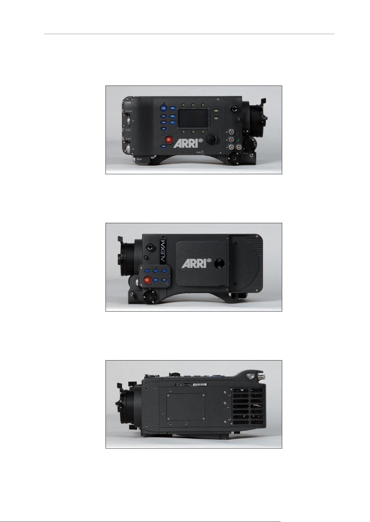
5 Layout of the ALEXA
Figure 1: ALEXA right
Figure 2: ALEXA left
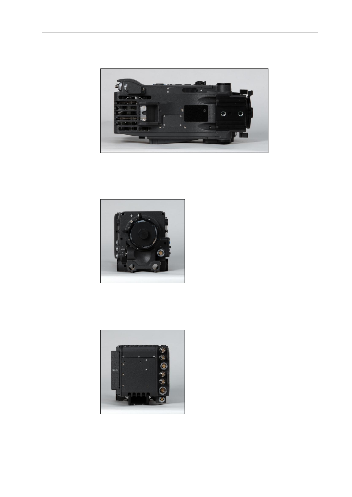
Figure 3: ALEXA top
Page 19
About This Manual 19
Figure 4: ALEXA bottom
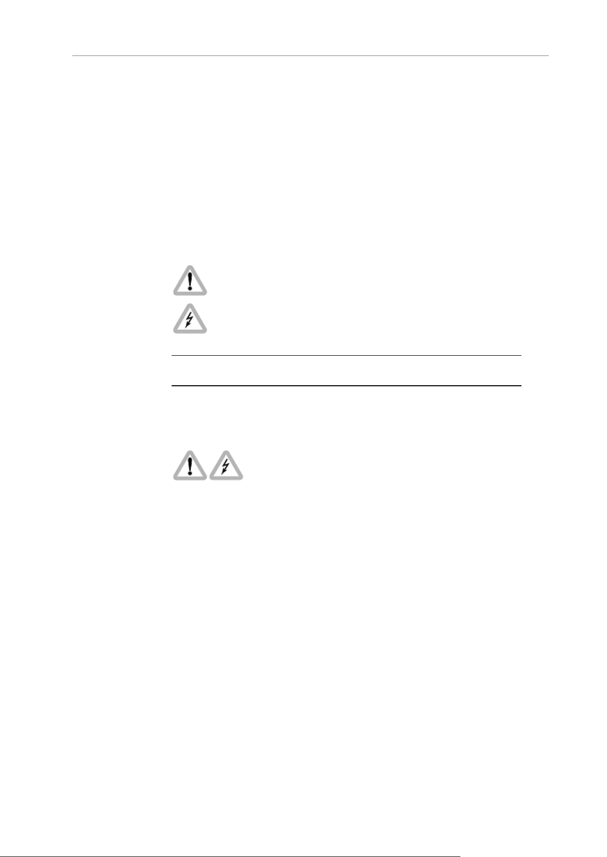
Figure 5: ALEXA front
Figure 6: ALEXA back
Page 20
20 Safety Guidelines
6 Safety Guidelines
Any violation of these safety instructions or non-observance of personal care
could cause serious injuries (including death) to users and affiliates and
damage to the equipment or other objects.
6.1 Explanation of Warning Signs and Indications
Indicates a possible risk of injury or damage to the equipment
Indicates the risk of electric shock or fire danger that could result in
injury or damage to the equipment.
Note: Indicates further information or information from other instruction manuals
6.2 General Safety Guidelines
Always follow these guidelines to ensure against injury to yourself or
others and damage to the system or other objects.
This safety information is in addition to the product specific operating
instructions in general and must be strictly observed for safety
reasons.
Read and understand all safety and operating instructions before you
operate or install the system!
Retain all safety and operating instructions for future reference.
Heed all warnings on the system and in the safety and operating
instructions before you operate or install the system. Follow all
installation and operating instructions.
Do not use accessories or attachments that are not recommended by
ARRI, as they may cause hazards and invalidate the warranty!
Do not attempt to repair any part of the system! Repairs must only be
carried out by authorized ARRI Service Centers.
Page 21

Specific Safety Instructions 21
6.3 Specific Safety Instructions
Do not remove any safety measures from the system!
Do not operate the system in areas with humidity above operating
levels or expose it to water or moisture!
Do not cover the fan openings at the camera back top and bottom!
Do not subject the system to severe shocks!
Do not place the system on an unstable trolley/hand truck, stand,
tripod, bracket, table or any other unstable support device! The
system may fall, causing serious personal injury and damage to the
system or other objects.
Operate the system using only the type of power source indicated in
the manual! Unplug the power cable by gripping the power plug, not
the cable!
Never insert objects of any kind into any part of the system if not
clearly qualified for the task in the manual, as objects may touch
dangerous voltage points or short out parts! This could cause fire or
electrical shock.
Unplug the system from the power outlet before opening any part of
the system or before making any changes to the system, especially
the attaching or removing of cables!
Do not use solvents to clean!
Do not remove any stickers or paint marked screws!
Always place a lens or a protective cap in the lens mount receptacle!
Never run a camera with a mirror shutter without a lens or a protective
cap in the lens mount receptable!
Changing camera lenses should be done in a dry and dust-free
environment. If this is not possible, take extra care that no dust enters
the camera while the lens is off!
When no lens is attached to the camera, immediately place the
protective on the lens mount to avoid contamination of the sensor
cover glass!
After changing lenses, always perform a dust check to make sure no
dust has settled on the sensor cover glass!
Clean optical lens surfaces only with a lens brush or a clean lens
cloth. in cases of solid dirt or grease, moisten a lens cloth with pure
alcohol. Discard contaminated lens cloth after use! Never attempt to
clean a lens brush with your fingers!
NEVER USE CANS WITH COMPRESSED AIR OR GAS TO BLOW
OFF THE DUST! This can severely damage optical elements.
If the sensor cover glass has been contaminated by solid dirt or
grease, special optical cleaning kits should be used for dirt removal
under very high care! If the contamination cannot be removed, the
camera should be taken to an ARRI service center for cleaning.
Page 22

22 Safety Guidelines
THE USE OF METHANOL TO CLEAN OPTICAL SURFACES IS NOT
RECOMMENDED!
NEVER USE ACETONE TO CLEAN OPTICAL SURFACES!
NEVER TRY TO REMOVE THE SENSOR COVER GLASS!
DO NOT POINT THE CAMERA INTO DIRECT SUNLIGHT, VERY
BRIGHT LIGHT SOURCES, OR HIGH-ENERGY LIGHT SOURCES
(e.g. laser beams)! This may cause permanent damage to the camera
image sensor.
DO NOT POINT THE VIEWFINDER INTO DIRECT SUNLIGHT,
VERY BRIGHT LIGHT SOURCES, OR HIGH-ENERGY LIGHT
SOURCES (e.g. laser beams)! This may cause permanent damage to
the viewfinder display and optical elements.
Page 23

Storage and Transport 23
7 General Precautions
7.1 Storage and Transport
Use a lens port cap to prevent damage to the sensor cover glass and
sensor whenever there is no lens attached.
Unplug all cables when transporting the Alexa in a camera case.
Do not store the camera in places where it may be subject to
temperature extremes, direct sunlight, high humidity, severe vibration,
or strong magnetic fields.
7.2 Electromagnetic Interference
ALEXA meets EC regulations by fulfilling the specifications of the European
Directive 2004/108/EC (15th December 2004).
This equipment has been tested and found to comply with the limits for a
Class A digital device, pursuant to part 15 of the FCC Rules. These limits are
designed to provide reasonable protection against harmful interference when
the equipment is operated in a commercial environment. This equipment
generates, uses, and can radiate radio frequency energy and, if not installed
and used in accordance with the instruction manual, may cause harmful
interference to radio communications. Operation of this equipment in a
residential area is likely to cause harmful interference in which case the user
will be required to correct the interference at his own expense.
Changes or modifications not expressly approved by the party responsible
for compliance could void the user's authority to operate the equipment.
Complies with the canadian ICES-003 Class A specifications. Cet appareil
numérique de la Classe A est conformé à la norme NMB-003 du Canada.
This device complies with RSS 210 of Industry Canada. This Class A device
meets all the requirements of the Canadian interference-causing equipment
regulation. Cet appareil numérique de la Class A respecte toutes les
exigences du Réglement sur le matérial brouilleur du Canada.
7.3 Condensation
When moving the camera from a cool to a warm location or when the
camera is used in a damp environment, condensation may form inside the
lens port, on the sensor cover glass, between the sensor and the sensor
cover glass, and on internal or external electrical connections.
Page 24

24 General Precautions
Operating the camera while condensation is present may result in
personal injury or damage to the equipment.
Condensation on the optical components may have a visible effect on the
output images. To reduce the risk of condensation:
Find a warmer storage location.
Attach the ARRI air-drying cartridge (silica bottle) to the PL-Mount of
the camera during storage
Note: Do NOT leave the air-drying cartridge attached to the PL-Mount
during transportation of the camera!
If camera needs to be stored in a place that is considerably cooler
than the location where it will be used, consider keeping the camera
powered from a mains unit in addition to using the air-drying cartridge.
In ambient temperatures above 30°C/86°F and/or humidity above
60%, always attach the air-drying cartridge to the PL-Mount of the
camera when not in use. This not only applies to storage, but also to
shooting breaks and situations when the camera remains without an
attached lens for an extended time.
MAKE SURE THE SILICA BOTTLE IS SECURELY FASTENED.
UNDER NO CIRCUMSTANCES SPILL SILICA INTO THE LENS
PORT!
Page 25

Power Management 25
8 Power Supply
Use only ARRI-recommended power supply solutions.
Manipulation of power supplies could result in serious injury or death,
or damage to the ALEXA.
The ALEXA accepts an input voltage range from 10.5 to 34 V DC. The
camera can be powered through the BAT connector or battery adapters
accepting V-Lock or Gold Mount batteries.
The power supply should deliver an output of more than 90 W to power the
camera sufficiently. The power draw of the camera in basic configuration is
about 85 W.
A 12 to 15 V battery should have at least 6 A maximum output current.
Note: when powering accessories through the camera, the total power draw of the
camera is increased by the amount of power drawn by the accessories.
8.1 Power Management
When using the BAT connector and one or more onboard battery adapters
simultaneously, the camera’s power management system ensures that the
power source with the highest voltage level is used. When the voltage level
of one power source drops below the level of the other, or a power source is
disconnected from the camera, the power management system
automatically switches to the other power source, avoiding shutdown of the
camera.
For example, a 12 V onboard battery can be used as backup for the main 24
V battery. Using a 12 V onboard battery in addition to the main 24 V battery
also allows for quick switchover to handheld mode—the power cable can
simply be disconnected from the BAT connector.
When using two onboard battery adapters (with batteries in parallel—one on
top and one on the back), the camera will treat them as a single source.
When used this way, the load is spread across two batteries, creating a
strong power source.
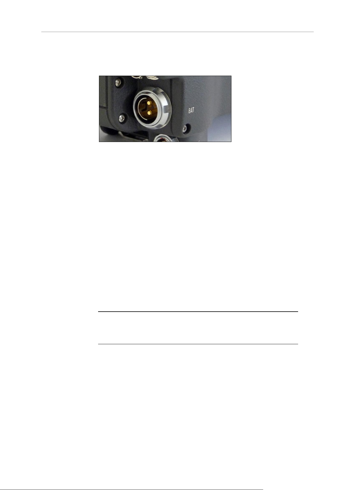
8.2 BAT Connector
The BAT connector is the primary power input on the ALEXA. It is a Fischer
2-pin socket located at the back of the camera on the camera-right side.
Page 26
26 Power Supply
The socket accepts power cables KC-20S and KC-29S. The cables can
either be connected to the mains unit NG 12/26R or to 24 V cine-style
batteries with three-pin XLR outputs.
Figure 7: BAT connector
8.3 Mains Unit NG 12/26 R
Use of the mains unit is recommended for shooting in the studio and when
using electronic accessories with high power consumption.
To power the ALEXA using the Mains Unit NG 12/26 R:
1. Set the correct mains voltage on the mains unit using the fuse on the
back of the unit. For example, set it to 220 V if the AC mains power
source is 220 V.
2. Connect the mains unit to AC mains power.
3. Ensure that the camera power is turned off.
4. Set the voltage switch on the mains unit to 26 V.
5. Connect the battery cable KC-20S or KC-29S (spiral cable) to the
power supply socket on the camera and the 26 V socket on the mains
unit.
Note: The NG 12/24 R was the original design that provided 12 & 24 volts output – it
was superseded by the NG 12/26 R, which outputs 12 & 26 volts. The NG 12/24 R
can easily be upgraded to NG 12/26 R specification at an ARRI service center.
8.4 Cine-Style Batteries
Any 24 V cine-style battery with a three-pin XLR output can be used to
power the camera through a KC-20S or a KC-29S.
The Anton/Bauer CINE VCLX/2 battery (280 Wh) with charger is available
from ARRI.
Page 27

Onboard Batteries 27
To connect the battery to the camera:
6. Ensure that the main switch on the camera is off.
7. Connect the battery cable KC-20S or KC-29S (spiral cable) to the
power supply socket on the camera and the 28V output on the battery.
Note: When the battery voltage drops below the warning level, the BAT1 level in the
camera display will start flashing. A white i will appear, signaling more information is
available on the INFO screen. For more information on setting the low battery
warning level, see Menu>System>Power (on page 102).
To charge the battery
1. Connect the charger to AC mains power.
2. Plug the charger cable into the charge input socket of the battery.
3. Charge the battery until complete. Fully charged batteries can be left
connected to the charger until required for shooting.
Note: For more information, refer to the Anton/Bauer CINE VCLX/2 manual.
8.5 Onboard Batteries
The camera can be equipped with adapters for either V-Lock or Gold Mount
video-style batteries. When a battery equipped with the TI-protocol for
battery communication is used, the ALEXA will display remaining capacity as
a percentage on the Home screen. For these batteries, the user does not
need to set the battery warning level.
Four different adapters are available:
BAB-G: Back-mount adapter Gold Mount batteries
BAB-V: Back-mount adapter V-Lock batteries
BAT-G: Top-mount adapter Gold Mount batteries
BAT-V: Top-mount adapter V-Lock batteries
Note: Adapters must be installed by a trained technician!
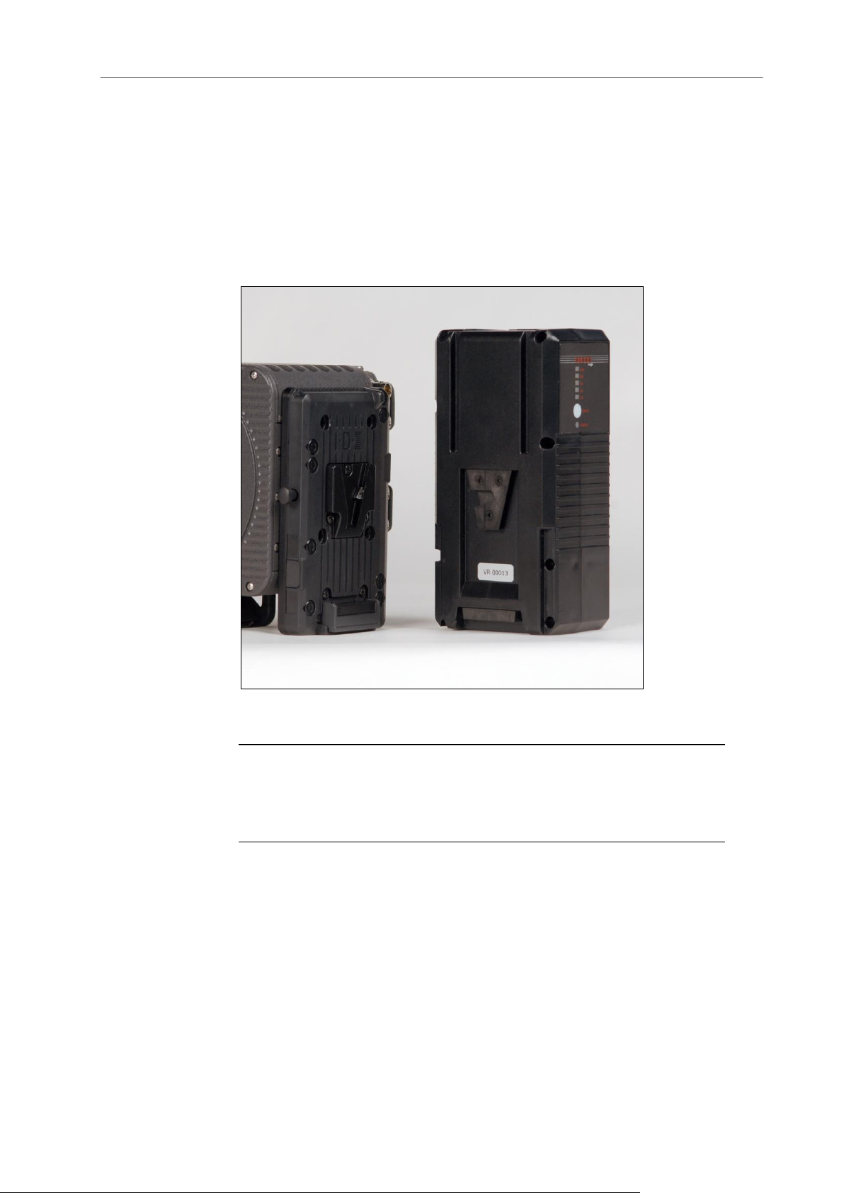
8.5.1 V-Lock Batteries
V-Lock batteries from different manufacturers may be used on the ALEXA.
When batteries from manufacturers such as ID-X and Bebop, are used, their
remaining capacity will be displayed as a percentage on the Home screen.
To attach a V-Lock battery:
1. Align the v-shaped wedge on the battery with the v-shaped notch on
the battery plate.
Page 28
28 Power Supply
2. Press the battery downwards until you hear a click.
3. Check that the battery is securely mounted on the battery plate.
To release a V-Lock battery:
1. Press the release button on the camera-left side or top of the battery
(manufacturer dependent).
2. While pressing the release button, slide the battery upwards.
Figure 8: ALEXA with BAB-V and V-Mount battery
Note: Not all V-Lock batteries deliver enough power to supply the camera. Use only
batteries with a capacity of 90 Wh or more to prevent damage to the battery and
unpredictable camera behavior. Any camera-battery combination should be tested
prior to use, especially when accessories are powered through the camera.
8.5.2 Gold Mount Batteries
If the ALEXA is equipped with a Gold Mount, Anton/Bauer batteries can be
used. Their remaining capacity will be displayed as a percentage on the
Home screen.
To attach a Gold Mount battery:
1. Align the three pins on the back of the battery to the three
corresponding holes on the battery plate.
2. Press the battery to camera-right until you hear a click.
Page 29
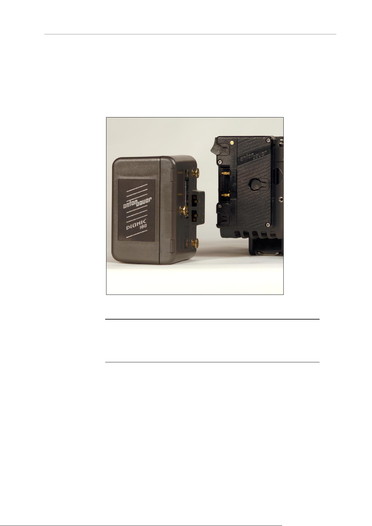
Onboard Batteries 29
3. Check that the battery is securely mounted on the battery plate.
To release a Gold Mount battery:
1. Press the release button on the camera-left side of the battery plate.
2. While pressing the release button, slide the battery camera-left, and
pull it straight out.
Figure 9: Camera with BAB-G and a Gold Mount battery
Note: Not all Gold Mount batteries deliver enough power to supply the camera. Use
only batteries with a capacity of 90 Wh or more to prevent damage to the battery and
unpredictable camera behavior. Any camera-battery combination should be tested
prior to use, especially when accessories are powered through the camera.
Page 30
30 Power Supply
8.6 Power Outputs
The ALEXA has two 24 V power outputs and one 12 V power output for
accessories. ALEXA Plus, ALEXA Plus 4:3 and ALEXA Studio models have
three 24 V power outputs and one 12V power output.
Figure 10: 24 V outputs (RS) and 12 V output
8.6.1 Powering 12 V Accessories
One 12 V output with a 2-pin LEMO connector is located on the right side of
the camera. It is limited to 12 V and can supply a device with a current of up
to 2.2 A, depending on the camera power supply.
8.6.2 Powering 24 V Accessories
Two 24 V remote start/stop (RS) outputs with 3-pin Fischer connectors are
located on the right side of the camera. They can supply two devices with a
combined load of up to 2.2 A (shared with the EXT connector power out),
depending on the camera power supply. When the camera is powered from
a source with a voltage below 24 V, they output 24 V. If the camera's power
source supplies more than 24 V, this voltage level is also present on the RS
outputs.
Besides powering accessories, the RS outputs can also be used to send a
remote start/stop signal to the camera.
Page 31

Minimum Equipment Recommended For Operation 31
9 Camera Support
Camera weight
lbs
kg
ARRI ALEXA incl. SxS module, EVF-1, VMB-1,
CCH-1, KC-150S
16.85
7.65
ALEXA camera body including SxS module
13.79
6.26
Electronic Viewfinder EVF-1
1.65
0.75
Viewfinder Mounting Bracket VMB-1
0.55
0.25
9.1 Minimum Equipment Recommended For Operation
ARRI ALEXA camera body including SxS module and Lens Adapter
PL mount without LDS (LA-PL-1)
EVF-1 Electronic Viewfinder
VMB-1 Viewfinder Mounting Bracket
KC 150-S Viewfinder Cable short 0.35m/1.2ft
CCH-1 Center Camera Handle
BP-12 Bridge Plate with base plate, or BPA-1 with BP-5/BP-8 Bridge
Plate and base plate, or WA-1 Wedge Adapter and Quick Release HD
Baseplate
SD card
Compatible power supply
Sony SxS PRO card for recording
9.2 Tripod and Remote Heads
Tripod and remote heads must have adequate load ratings to support the
ALEXA and attached accessories. See the following table for camera and
component weights.
Note: Always check the payload limits of a remote head and crane before mounting a
camera.
In applications where the camera mount is subject to high forces (e.g. car or
helicopter mounts) the camera must be additionally secured with appropriate
safety restraints. All mount screws must be tightened firmly with an
appropriate screwdriver (not with the commonly used coin!).
Page 32

32 Camera Support
Viewfinder Cable short KC-150S
0.26
0.12
Center Camera Handle CCH-1
0.60
0.27
9.3 Electronic Viewfinder EVF-1
The electronic viewfinder EVF-1 employs a liquid crystal on silicon (LCOS)
imaging device with a temperature-stabilized LED light source to provide a
bright, accurate view of the sensor image in all operating conditions. Each
EVF-1 is calibrated to precisely match the image on the ALEXA's HD
outputs.
The EVF-1 has a resolution of 1280x720 pixels, with 32 additional lines of
resolution above and 32 below the image to display camera status
information. The EVF-1 can also display a 10% surround view area of the
sensor to help the operator track unwanted elements before they enter the
recorded image area. Focus can be checked by temporarily zooming into the
image with a magnification factor of 2.25x. The low-latency interface of the
EVF-1 has a delay of less than 1 frame.
The EVF-1 has button controls for false color check and zoom, as well as
buttons and a jogwheel to control EVF and camera settings.
Page 33

Electronic Viewfinder EVF-1 33
Connect the viewfinder to the camera using the viewfinder mounting bracket
Model
Length
(m / ft)
Suggested use
KC-150-S
0.35 / 1.2
For use of EVF-1 on camera left side in
handheld mode
KC-151-S
0.65 / 2.1
For use of EVF-1 on camera right side or
when using Viewfinder Extension Bracket
VEB-1
KC-152-S
2.00 / 6.6
Longest possible length for use with specialty
rigs
VMB-1.
Figure 11: Camera with EVF-1
Note: Do not point the viewfinder eyepiece at direct sunlight or bright light sources, as
this could damage the LCOS imaging device. If possible, cover the eyepiece when
not in use to prevent any damage.
9.3.1 Viewfinder Cables
The viewfinder cables are unidirectional with a male plug to connect to the
camera and a female plug to connect to the viewfinder.
Cables are available in the following lengths:
Page 34

34 Camera Support
Figure 12: EVF cables: KC-150S (center), KC-151S (middle), KC-152S
(outer)
9.3.2 Viewfinder Mounting Bracket
The Viewfinder Mounting Bracket VMB-1 / VMB-2 is attached to the camera
using two captive 3mm hex socket head screws on top of the camera at the
front. Attach the EVF-1 to the Viewfinder Mounting Bracket by sliding the
dove tail into the receptacle and closing the lever on the EVF-1.
The position of the EVF-1 can be adjusted by loosening the levers on the
Viewfinder Mounting Bracket, adjusting the position as desired and closing
the levers to retighten.
The EVF-1 can be mounted on the camera-right side by unscrewing the
threaded end cap on the side-to-side adjustment rod, removing the rod itself
and inserting it from the other side. Remember to reattach the threaded end
cap.
Note: Camera-right operation is not possible with the standard EVF cable KC-150-S.
Instead, the longer cable KC-151-S is needed.
Figure 13: VMB-1 on camera
Page 35

Electronic Viewfinder EVF-1 35
The Viewfinder Extension Bracket VEB-1 extends the mounting point of the
EVF-1 further back. It can be attached to a tripod head for use with geared
heads or greater comfort when using fluid heads using itsstandard
attachment point for the ARRI Eyepiece Leveler EL-3. To avoid damage to
the VMB-1/VMB-2 when using the VEB-1 with an eyepiece leveler, loosen
the friction on VMB-1/VMB-2’s rotating assembly.
Figure 14: EVF extension bracket
Figure 15: Camera with EVF-1 on extension and cable KC-151S
Page 36

36 Camera Support
9.4 Center Camera Handle CCH-1
The Center Camera Handle CCH-1 is attached to the camera top with three
captive 3mm hex socket head screws (two at the front and one at the back).
Ensure that the CCH-1 is securely fastened before attempting to lift the
camera from it.
Figure 16: Camera with CCH-1, side view
Page 37

Side Camera Handle SCH-1 37
The Handle Extension Block HEB-2 mounts to the front end of the CCH-1
and adds one more focus hook to the camera in a high position, allowing the
tape measure to clear the matte box.
9.5 Side Camera Handle SCH-1
The Side Camera Handle SCH-1 is used in conjunction with a BAT-V or
BAT-G top-mounting battery adapter, or with third-party onboard recorders. It
is attached to the camera using three captive 3mm hex socket head screws
(two at the front and one at the back). Ensure that the SCH-1 is securely
fastened before attempting to lift the camera from it.
If a tall battery or a tall third-party onboard recorder is used, the adjustable
center grip of the SCH-1 can be replaced by the taller Adjustable Center Grip
Tall (ACG-2).
Page 38

38 Camera Support
Figure 17: SCH-1
Figure 18: Camera with SCH-1, side view
9.6 Bridge Plates BP-12/BP-13
The bridge plate BP-12 for 19 mm studio rods has been newly developed for
ALEXA. It mounts directly to the camera body using two 3/8"/16 screws and
ensures that support rods, matte boxes and follow focus units are positioned
properly in regards to the optical center of the camera, just like all other
ARRI cameras.
Page 39

Bridge Plate adapter BPA-1 39
The bridge plate BP-13 is equivalent to the BP-12, but for 15 mm studio
rods.
Note: Make sure bridge plates are tightened firmly with a screwdriver, not the
commonly used coin!
9.7 Bridge Plate adapter BPA-1
The bridge plate adapter BPA-1 can be used to attach a BP-3/BP-5/BP8/BP-9 to ALEXA. First attach the BPA-1 to the camera with the two screws.
Then attach the bridge plate to the adaptor with its two screws. Make sure
the screws are tightened firmly with a screwdriver.
Page 40

40 Camera Support
9.8 Wedge Adapter WA-1 and QuickRelease Plate QR-HD-1
The WA-1 can be mounted at the same position as a bridge plate. It has a
dove tail that slides into the counter part of a quick-release plate, like the
ARRI QR-HD-1. The quick-release plate has a pin at its back, which fits into
the pin receptacle at the back of the camera base.
Figure 19: ARRI QR-HD-1
9.9 Leveling Block LB-1
The Leveling Block LB-1 attaches to the bottom of the ALEXA in the pin
receptacle on the back foot. It prevents the camera from resting on a rearmounted battery when a bridge plate is attached and the camera is placed
on a flat surface.
Attach the LB-1 by inserting its pin into the pin receptacle at the end of the
shoulder arc in the camera base. Twist the knob clockwise to tighten.
Figure 20: Leveling Block LB-1
Page 41

Shoulder Pad SP-3 41
9.10 Shoulder Pad SP-3
The camera base has an integrated arch to fit to the operator's shoulder. For
extended handheld shots, the newly designed shoulder pad SP-3 can be
attached to the base of the camera with velcro.
Note: The SP-3 can only be used with a BP-12 and 19 mm rods or with 15 mm rods
and a Wedge Adapter WA-1 and a Quick-Release Plate QR-HD-1 . When using the
BPA-1 with a BP-5/BP-8, the bridge plate has to be removed prior to attaching the
SP-3.
Figure 21: SP-3 shoulder pad
Figure 22: SP-3 below camera
Page 42

42 Connectors
10 Connectors
Camera back
Figure 23: Connectors at back
From top to bottom: MON OUT, RET/SYNC IN, EXT, REC OUT 1, REC
OUT 2, BAT, ETHERNET
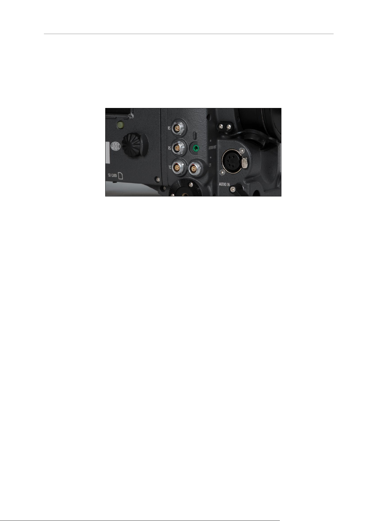
Camera right
Figure 24: Connectors on right side
From left to right, top to bottom: 2x RS (24 V) out, AUDIO OUT, TC, 12V out,
AUDIO IN, SD CARD (camera bottom)
Page 43
Shoulder Pad SP-3 43
Camera left
Figure 25: Camera left
Top to bottom: SxS slot 1, SxS slot 2
Camera front
Figure 26: Camera front
EVF connector
Page 44

44 Connectors
10.1 BAT
The BAT connector can be used to power the camera from an external
power source with cables KC-20S and KC-29S.
It is located at the back of the camera on the camera-right side.
10.2 REC OUT 1 + 2
The REC OUT consists of two BNC connectors capable of carrying
1920x1080 1.5G or 3G HD-SDI signals with frame rates from 23.976 to 60
fps according to SMPTE standards 274M, 292M, 372M and 425M (Level B).
In addition, it outputs ARRIRAW in a proprietary format that is supported by
a range of third-party recorders. RGB 444 at frame rates of 48, 50, 59.94
and 60 fps is output in a proprietary format utilizing two 3G connections. The
signal format can be changed in the Recording menu.
The connectors are located at the back of the camera on the camera-right
side.
10.3 RET/SYNC IN
A return signal from another image source can be fed into the ALEXA’s RET
connector for displaying on EVF and/or MON OUT. The signal must be a
1920x1080 422 1.5G single link according to SMPTE 274M and 292M. The
output routing of the RET in signal can be set in the Monitoring menu.
The connector is located at the back of the camera on the camera-right side.
10.4 MON OUT
The MON OUT is a single BNC connector capable of carrying a 1920x1080
422 YCbCr 1.5G HD-SDI signal with frame rates of 23.976, 24, 25, 29.97 or
30 fps according to SMPTE standards 274M and 292M. The signal format
can be changed in the Monitoring menu.
The connector is located at the back of the camera on the camera-right side.
10.5 EXT
The EXT connector is a multi-pin accessory connector that carries signals for
communication with various accessories and 24V power. The maximum
power output is 2.2A, shared with the RS outputs.
Cables are currently available for:
Connecting a UMC-3 remote motor controller
Page 45

ETHERNET 45
(model UMC Connection Cable (0.80m/2.6ft) K-UMC3-ALEXA)
Connecting two ALEXA cameras for synchronized operation
(model EXT to EXT Cable (2.00m/6.6ft) KC 155-S)
The connector is located at the back of the camera on the camera-right side.
10.6 ETHERNET
Standard ethernet connectors can deliver neither the power nor the durability
and reliability required by ARRI, so the ALEXA uses a specially designed 10pin LEMO connector. The ARRI KC-153-S cable is required to connect the
Ethernet socket to a standard RJ-45 Ethernet port.
The ethernet port can be used to operate two ALEXA cameras with synced
settings by connecting the cameras with a KC 156-S cable, or to connect the
Remote Control Unit RCU-4 to the camera.
The ethernet connector can output 24 V with 1.2 A power.
The connector is located at the back of the camera on the camera-right side.
10.7 EVF
The EVF connector connects the camera to an EVF-1 electronic viewfinder.
The signals on this connector are proprietary and can only be used to drive
an EVF-1. This proprietary signal assures low latency for the viewfinder
image.
The connector is located at the front of the camera on the camera-left side.
10.8 AUDIO IN
2-channel analog line-level audio can be fed to the camera via the 5-pin XLR
connector located at the front of the camera on the camera-right side.
The ALEXA converts the audio signal from analog to 24 bit 48 kHz PCM.
10.9 RS
The two RS connectors supply external accessories with at least 24 V power
and a combined load of up to 2.2 A (shared with the EXT connector power
out). The sockets also accept an ARRI remote start/stop trigger.
The connectors are located at the front of the camera on the camera-right
side.
Page 46

46 Connectors
10.10 12 V
The 12 V connector supplies an external accessory with 12 V power and up
to 2.2 A current.
The connector is located at front of the camera on the camera-right side.
10.11 TC
The TC connector is a 5pin LEMO socket. It accepts and distributes a
Longitudinal Time Code (LTC) signal.
It can be used to
jam-sync the ALEXA’s time code to a Clockit, TC Slate or another
camera
transmit the ALEXA’s time code to a Clockit, TC Slate or another
camera
tune the frequency of the ALEXA’s crystal oscillator with an Ambient
ACC Clockit Controller
The connector is located at the front of the camera on the camera-right side.
10.12 AUDIO OUT
The AUDIO OUT is a 3.5mm TRS connector (headphone jack), which
outputs audio fed to the 5-pin XLR AUDIO IN connector with a maximum
power of 2.5 dBm.
The connector is located at the front of the camera on the camera-right side.
Note: Connecting a headphones to the camera while recording can cause a short
audio signal interruption due to static electricity.
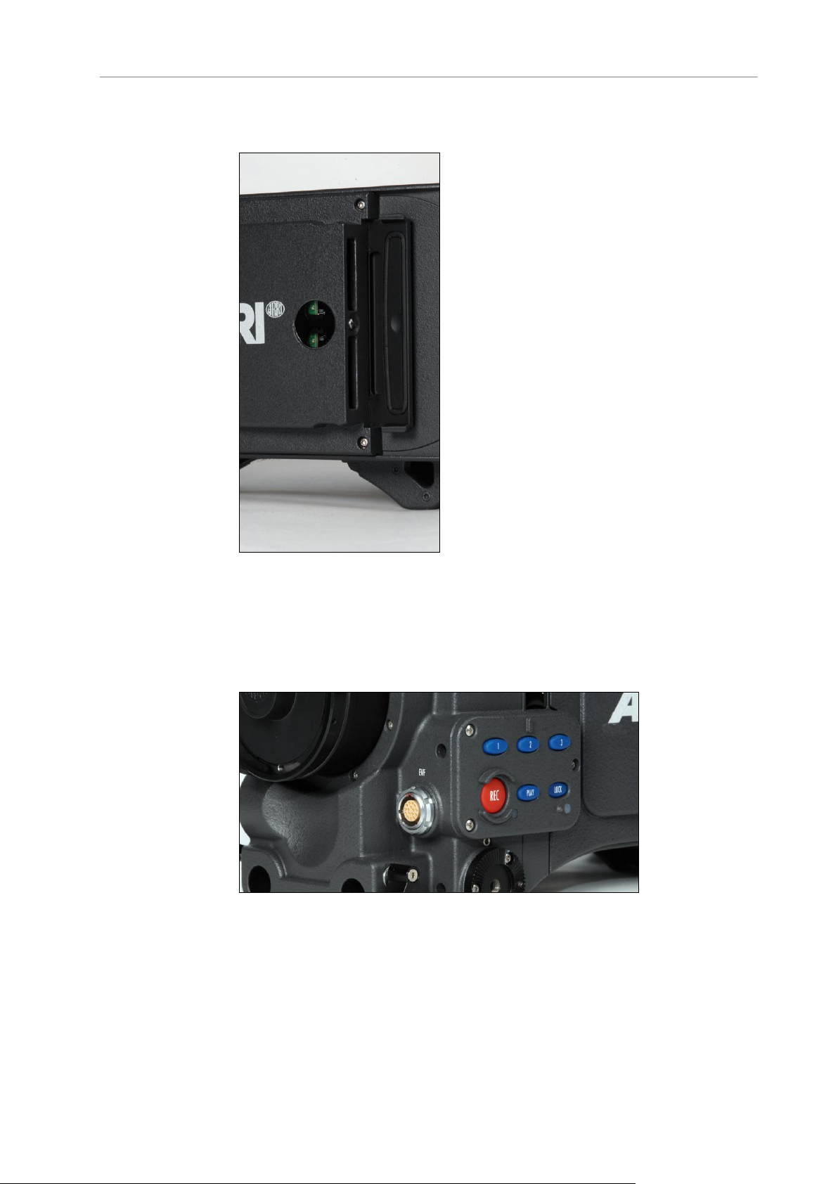
10.13 SD Card
The ALEXA saves data such as user setups, frame grabs and system logs to
an SD card. Firmware, additional frame lines and ARRI Look Files are
loaded onto the camera from the SD card. The SD card slot is located on the
bottom of the camera on the camera-right side. To access the SD card slot,
slide the door towards the front of the camera.
SD Card Requirements
SD or SDHC card (most brands are compatible)
maximum capacity of 4GB
Page 47

SD Card 47
FAT or FAT32 format
Note: Keep the SD card slot door closed to prevent dirt and moisture from entering
the camera.
The SD card can be formatted on the ALEXA or the following folder structure
can be created manually on a computer. The SD card must be properly
formatted prior to its first use.
Figure 27: Folder structure required for SD card
To format an SD card on the ALEXA:
1. Press the MENU button.
2. Using the jogwheel, select System.
3. Select SD Card.
4. Select Format + prepare SD card.
5. Press both FORMAT buttons simultaneously. The ALEXA will create
the required folder structure on the SD card after formatting.
Note: Formatting the SD card will irreversibly remove all data on the SD card.
To create the required folder structure on the SD card in the ALEXA
without formatting:
1. Press the MENU button.
2. Using the jogwheel, select System.
3. Select SD Card.
4. Select Prepare SD card. The ALEXA will create the required folder
structure on the SD card without formatting or deleting any data.
Note: Firmware update files are recognized by the camera anywhere within the
structure, but it is recommended to copy the them into the Firmware folder.
Page 48

48 Connectors
10.14 SxS Slots
The ALEXA records clips using the SxS module on the camera-left side. The
two SxS card slots can be accessed by opening the SxS door towards the
camera body. The SxS door was designed for accessibility when the ALEXA
is operated in confined spaces or mounted on rigs such as remote heads.
Note: Keep the SxS slot door closed to prevent dirt and moisture from entering the
camera.
To load an SxS card:
1. Insert the SxS PRO card into the SxS slot with the contacts facing the
front of the camera and the label facing out (away from the camera
body).
2. Push the card in against the spring until the lock engages.
3. Close the SxS door.
Note: Do not force an SxS PRO card into the slot backwards or with the label-side
in—the contacts in the SxS module and the SxS PRO card could be damaged.
Note: Do not force the SxS door closed if the SxS PRO card is not fully inserted and
the lock engaged.
To release an SxS card:
Push the SxS PRO card in until the lock disengages, taking care to
prevent the card from dropping out of the SxS slot.
SxS PRO cards do not have to be mounted or unmounted—they can be
inserted or removed whenever the camera is not recording to the SxS
module. If a card is removed during recording, only the last second of the
current clip will be lost. All clips on the card will remain accessible and the
card will remain fully functional.
Note: If the recording process is interrupted by power loss or card removal, transfer
all the data from the SxS PRO card and format it before using it again.
To toggle between SxS slots:
With the SxS door open, press the metal card select button located
between the SxS slots. The active SxS slot is indicated by the LED in
the SxS window.
Explanation of SxS LED States
Each card has an LED that signals the SxS PRO card's state to the user.
Page 49

SxS Slots 49
LED state
Card state
Off
No card present
Card is unreadable (e.g. wrong file system)
Card is inactive
Solid green
Card is selected and ready
Solid red
Card is accessed (read/write)
DO NOT REMOVE THE CARD!
Note: Only Sony SxS PRO cards can be used with ALEXA. Sony SxS-1 cards are
not supported.
Page 50

50 Lens Mounting
11 Lens Mounting
The ALEXA is equipped with an interchangeable lens mount. Available
adapters include:
Lens Adapter PL Mount LA-PL-1
Lens Adapter Panavision Mount LA-PV-1
Note: Lenses must cover an image circle of at least 30 mm in diameter to prevent
vignetting.
11.1 Lens Adapter PL Mount LA-PL-1 (no LDS)
The Lens Adapter LA-PL-1 is the standard lens mount delivered with the
ALEXA. It can be used to attach any modern PL-mount lens to the camera.
To mount a PL-mount lens:
1. Turn the bayonet ring anti-clockwise until it stops.
2. Remove the lens port cap.
3. Carefully insert the lens into the lens port. Align the notch in the lens
flange with the index pin on the mount, keeping the lens rotated into a
position where the lens markings are visible from either side of the
camera.
4. Press the lens flange flat onto the lens mount.
5. Turn the bayonet ring clockwise until the lens is locked securely.
6. Ensure that the lens is properly mounted.
Note: When no lens is attached to the camera, use the lens port cap to prevent dust
from entering the lens cavity.
Note: The sophisticated design principle of the camera’s optical module delivers
outstanding images with a cinematic look and feel, but also makes the imager
sensitive to contamination. Dust particles that have settled on the sensor cover glass
during a lens change may become visible as dark spots in the output image, similar
to lint leaving marks on exposed film. The degree of this effect depends on the
aperture of the lens.
Page 51

Lens Support 51
Figure 28: PL mount LA-PL-1 with index pin
11.2 Lens Support
Heavy lenses may require additional lens support. Using a lens support
guarantees that the weight of the lens will not influence the flange focal
depth and reduces stress on the lens mount.
To support a lens use 15mm studio or 19mm studio rods and an appropriate
lens bridge. 15mm studio rods require a bridge-plate with 15mm studio rod
support, such as a BP-3/BP-9 + BPA-1, while 19mm studio rods require a
bridge-plate with 19mm studio rod support, such as a BP-12 or BP-5/BP-8 +
BPA-1.
Mount the lens bridge LS-10 for 15 mm studio rods by pushing it onto the
rods from the front. Mount the lens bridge LS-9 for 19 mm studio rods by
clipping it on the rods from the top.
Page 52

52 Lens Mounting
Slide the bridge into position on the rods directly under the lens support ring
on the lens, and fix it in place by tightening the lever on its side. Align and
tighten the center screw in the lens support ring, adjusting the height of the
center screw with the lever on the back of the lens bridge.
Figure 29: Camera with BP-12, 19mm studio rods and lens bridge
Page 53

Lens Support 53
12 Camera Controls
Main controls
Location: camera-right side
Interface: 3-inch LCD-screen with floating-function
buttons, a jogwheel to navigate through menus
and adjust parameters, and a range of fixedfunction buttons.
Operator controls
Location: camera-left side
Interface: three assignable function buttons plus
three fixed-function buttons for easy operator
access.
EVF controls
Location: Electronic Viewfinder EVF-1
Interface: fixed function buttons and a jogwheel
for adjustment of viewfinder parameters and
primary shooting parameters.
The ALEXA can be controlled through three user interfaces:
Page 54

54 Camera Controls
12.1 Main Controls
The main controls can be used to set all camera parameters.
Figure 30: Main controls
12.1.1 Display
The 3-inch LCD has a resolution of 400x240 pixels. The back-lit, transflective
display has exceptional contrast even in bright sunlight.
To adjust the LCD brightness:
On the HOME screen, rotate the jogwheel while pressing the BACK
button.
A removable plastic shield protects the display from scratches. It can be
removed by pulling it off the four pins.
12.1.2 Screen Buttons
Six screen buttons are located above and below the LCD display. Their
function varies depending on the screen content and is shown directly above
or below each button. If no function is shown above or below a button on the
LCD, it has no function for that screen.
Page 55

Main Controls 55
As a failsafe, operations that cannot be reversed and can result in the loss of
Button
Function
FPS
Sets the frame rate of the sensor, adjustable from 0.750-60.000 fps
in Regular Speed Mode, and from 60.000-120.000 fps in High
Speed Mode.
Note: High Speed Mode can only be activated with a valid High
Speed license key installed in the camera.
AUDIO
Shows the current audio level. If AUDIO is set to Off, the audio
input is switched off: no audio is embedded in the HD-SDI outputs,
and no audio tracks are recorded on the SxS PRO cards. The same
applies if AUDIO is disabled, which is the case if the sensor frame
rate is different from the project fps setting (for example, while overor undercranking).
SHUTTER
Sets the shutter angle of the sensor, adjustable from 5.0-358.0°.
Shutter angle and sensor fps determine exposure time of the
sensor in seconds by the following equation: angle/(360*fps).
Note: In High Speed mode, the shutter angle is limited to a
maximum of 356.0°.
EI
Sets the exposure index rated in ASA. The ALEXA has a base
sensitivity of 800 ASA. The camera’s EI rating can be adjusted from
160 to 3200 ASA.
data require pressing two buttons simultaneously to confirm the operation.
12.1.3 HOME screen
Figure 31: HOME screen
The HOME screen is the ALEXA’s default screen. It shows the most
important camera parameters and gives quick access to changing them
through the screen buttons. To return to the HOME screen from any menu in
the camera, press the HOME button.
Note: To adjust the LCD brightness from the HOME screen, rotate the jogwheel while
pressing the BACK button.
Screen buttons
Page 56

56 Camera Controls
Note: ASA rating is identical to ISO rating.
Note: Exposure Index is not applied to ARRIRAW signals.
COLOR
Opens the color screen, where gamma and look settings for SxS,
REC OUT, MON OUT and EVF can be changed.
WB
Sets the camera’s white balance. This is the color temperature of
the light source that the ALEXA is currently adjusted for. The white
balance can be adjusted from 2000 to 11000 Kelvin in steps of 100
Kelvin. In addition to the red/blue correction of the white balance,
the ALEXA can also compensate for a green/magenta tint. This
value, called CC (color compensation), is shown as an exponent of
the WB value. Positive values are marked with a "+" and negative
values with a "-".
The user can execute an automatic white balance by pressing the
AUTO WB button in the WB screen.
Camera Status Section
TC
Displays the current time code including the source (INT:
internal, EXT: external source). Frames are not displayed. The
timebase of the time code is shown after the @ sign.
Camera is set to Ext sync: MASTER
Camera is set to Ext sync: SLAVE
Settings sync is active
BAT 1
The voltage level of the power source present at the BAT
connector, or the remaining capacity of an attached battery in
percentage if it transmits this information.
BAT 2
The voltage level of a battery attached to the onboard battery
adapter, or the remaining capacity of an attached battery in
percentage if it transmits this information.
REEL
Identifies the current reel with the camera index letter, such as A
or B and the reel number.
CLIP
Identifies the current clip with the clip index and clip number.
DUR
Displays the duration of the current clip during recording or the
length of the last recorded clip while in standby in the format
h:mm:ss.
Capacity of the currently active SxS PRO card in minutes. It is
calculated for the current framerate and codec.*
<
Marks the active SxS PRO card.
The camera is in standby and ready to record.
The camera is recording.
An error occurred and recording is not possible. Press the INFO
button for more information.
If nothing is shown, the camera has detected no errors, but no
SxS PRO card is present for recording.
* Note: When SxS recording is set to ProResTM, the value shown is the minimum
available recording time for the current sensor frame rate and codec combination.
Page 57

Main Controls 57
Apple ProResTM is a variable bit rate codec, so the actual remaining recording time
Name
Icon
Description
General Warning
Important information is waiting on the INFO
screen.
General Error
An error has occurred. Check the INFO screen for
more information.
Temperature
Warning
There is a minor sensor-temperature offset. Image
quality may be slightly affected.
Temperature Error
There is a substantial sensor-temperature offset.
Image quality may be seriously affected.
Lock
The Main Controls are locked.
SD Card
An SD card is present. The icon turns orange when
the card is accessed.
Grab
The GRAB icon flashes while a still frame is being
taken and written to the SD card.
High Humidity Mode
The sensor is in High Humidity mode (i.e. the
sensor is kept at 40° C sensor temperature to
avoid condensation).
Radio
The WRS radio is active (ALEXA Plus only).
depends on the image content.
When using Avid's DNxHD, the remaining recording time is accurate.
Icons
Note: A sensor temperature warning or error after boot-up is normal as the sensor
takes a few seconds to reach its preset temperature.
12.1.3.1 Lists and User Lists
On the HOME screen, press the FPS, SHUTTER, WB (white balance) and
EI (exposure index) buttons to open lists of preconfigured values for each
setting.
User-defined values can be added to the FPS, SHUTTER and WB lists. The
EI list is fixed and user-defined values cannot be added. It contains values
from 160-3200 ASA in steps of 1/3 stops.
Page 58

58 Camera Controls
Setting a list value
Figure 32: SENSOR FPS screen
Any value in a list may be set. Invalid values will appear grayed out.
To set a list value:
1. Rotate the jogwheel to select the desired list value.
2. Press the jogwheel to set the list value.
Adding a list value
If the desired list value does not appear in the list, a user-defined value can
be added.
To add a list value:
1. Press the ADD button.
2. On the ADD screen, use the jogwheel and + or – buttons to enter a new
list value.
3. When you are finished entering the new list value, press the jogwheel
to add it to the list.
Note: Each list supports a maximum of 16 entries. To add new user-defined list
values to a full list, you must delete previously added user-defined list values.
Deleting a list value
User-defined list values that are no longer required can be deleted.
To delete a list value:
1. Press the DELETE button.
2. On the DELETE screen, use the jogwheel to select the user-defined
value you wish to delete.
3. Press both DELETE buttons simultaneously.
Page 59

Main Controls 59
Note: Preconfigured values cannot be deleted and will appear grayed out on the
DELETE screen.
Figure 33: DELETE SENSOR FPS screen
Note: The EI list is static and cannot be changed by the user. It contains ASA values
from 160-3200 ASA in steps of 1/3 stop.
12.1.3.2 FPS
Press the FPS (frames per second) button on the HOME screen to open the
SENSOR FPS list screen, which lists the default frame rates as well as user-
defined frame rates.
Figure 34: SENSOR FPS screen
Note: Access to this screen is disabled during record.
The maximum frame rate that can be set is dependent on the type of SxS
PRO card and the codec.
The following table shows the maximum available frame rate for all
codec/card combinations.
Page 60

60 Camera Controls
Codec
SxS PRO
8-32 GB
SxS PRO
64 GB
16:9 HD
ProRes 422 Proxy
60 fps
(120 fps)
1
60 fps
(120 fps)
1
ProRes 422 LT
60 fps
(120 fps)
1
60 fps
(120 fps)
1
ProRes 422
60 fps
60 fps
(120 fps)
1
ProRes 422 HQ
60 fps
60 fps
(120 fps)
1
ProRes 4444
40 fps
60 fps
DNxHD
115/120/145
60 fps
60 fps
(120 fps)
1
DNxHD
175x/185x/220x
60 fps
60 fps
(120 fps)
1
16:9 2K
ProRes 422 Proxy
through 422 HQ
60 fps
60 fps
ProRes 4444
40 fps
60 fps
4:3 2K
ProRes 422 Proxy
through 422
48 fps
48 fps
ProRes 422 HQ
40 fps
48 fps
ProRes 4444
30 fps
48 fps
1
By installing a High Speed licence, the maximum available frame rate can
be increased to 120 fps.
If the desired frame rate cannot be set because it is grayed out, change the
SxS codec to one with a lower data rate. For example, when using a 32 GB
SxS PRO card and the ProRes 4444 codec, 60.000 fps will be grayed out.
Set the ProRes 422HQ codec to enable 60.000 fps.
There are shortcut buttons on the FPS screen for SxS CODEC, SxS INFO
and SDI FPS. In the SDI FPS screen, both MON OUT and REC OUT frame
rates can be adjusted within the limits of their current format.
Setting sensor fps through REC OUT fps
When the FPS button is pressed on the HOME screen and the sensor frame
rate is linked to the REC OUT frame rate, a message appears instead of the
list. While this setting is active, the sensor frame rate can only be set by
setting the REC OUT frame rate.
Page 61
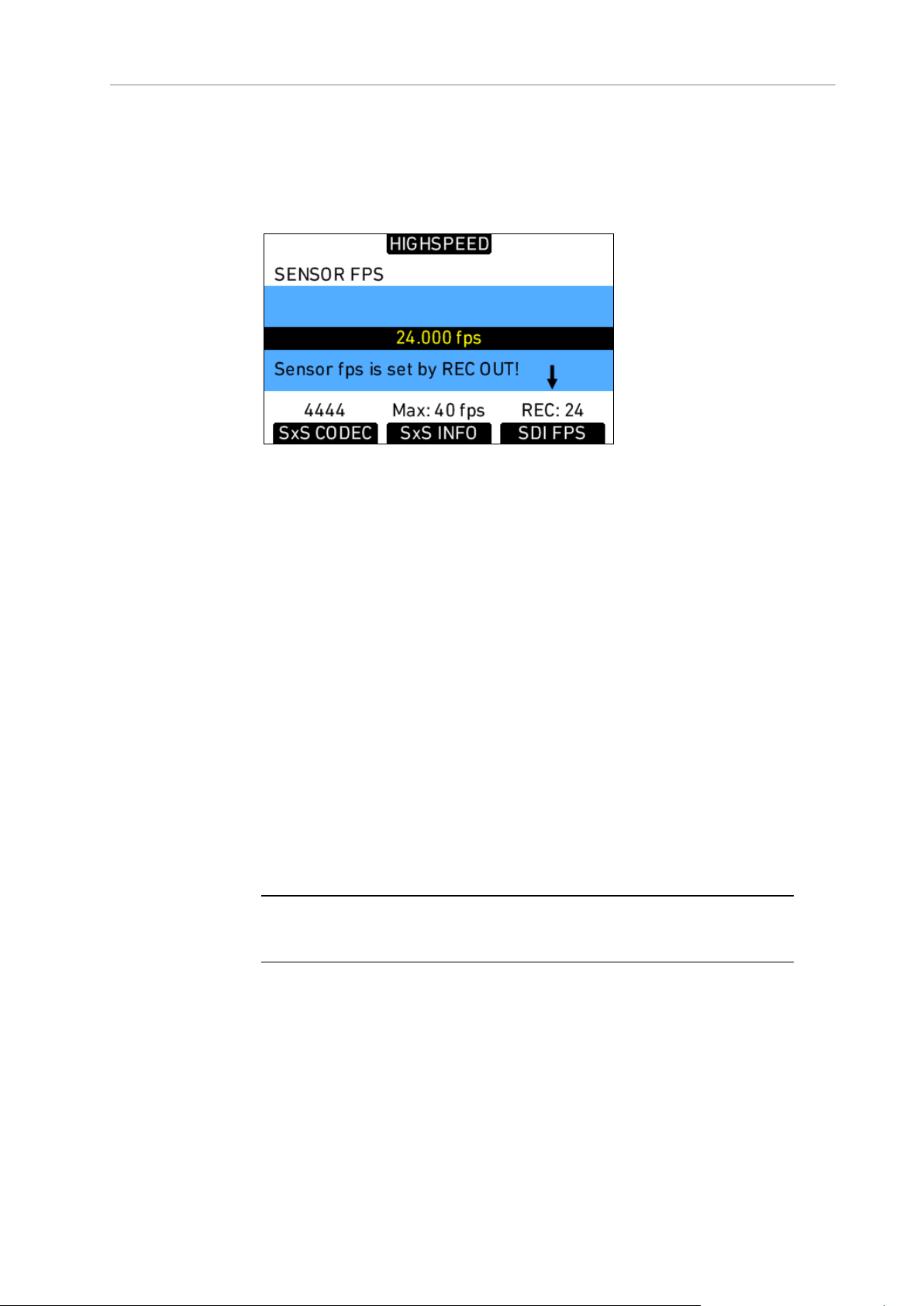
Main Controls 61
To link or unlink the sensor frame rate to the REC OUT frame rate:
1. Press the MENU button.
2. On the Recording menu, use the jogwheel to select REC OUT.
3. Select REC OUT fps sets sensor fps and set On or Off.
Figure 35: SENSOR FPS screen with linked sensor frame rate
Setting the correct frame rates when recording with external devices
When recording ARRIRAW or the 444 signal from the ALEXA to an external
recorder, correct frame-rate settings are critical. Mismatched sensor and
REC OUT frame rates could result in dropped frames and lost footage.
Setting the sensor frame rate determines the number of frames per second
generated by the sensor. The range is 0.750 to 60.000 frames per second.
The images are then processed by the camera electronics for the different
output paths.
The REC OUT is the recording output path, which transmits images to an
external recorder. The REC OUT frame rate is limited to standard speeds.
Ideally, the REC OUT frame rate matches the sensor frame rate. If the REC
OUT frame rate is lower than the sensor frame rate, the images cannot be
output as fast as they are created by the sensor, resulting in dropped frames
and loss of data.
Note: If the REC OUT frame rate is lower than the sensor frame rate, a ! warning will
appear over the SDI FPS button.
If the REC OUT frame rate is higher than the sensor frame rate, duplicate
frames are output over the REC OUT. For example, if the sensor is set to 10
fps and the REC OUT is set to 30 fps, every image is output three times,
resulting in two duplicate frames following every active frame. A standard
recorder would record these duplicate frames, which would have to be
removed in post.
To prevent this extra step, the ALEXA marks the duplicate frames with a
Variflag. If the recorder supports Variflag recording, it will discard the
duplicate frames and only record the active frames. This saves valuable
storage space and post-production work.
Page 62

62 Camera Controls
The MON OUT should match the sensor and the REC OUT frame rate. If the
sensor frame rate exceeds the available MON OUT frame rates, set the
MON OUT to half the sensor frame rate if possible to maximize the
smoothness of the image when panning and tilting.
To correctly set frame rates for the REC OUT:
1. Press the MENU button.
2. Using the jogwheel, select the Recording menu.
3. Select REC OUT.
4. Set Frame rate to the desired frame rate. This frame rate should match
the frame rate setting on the external recorder.
5. If the desired sensor frame rate is a standard speed, set REC OUT fps
sets sensor fps to On.
6. Press the HOME button to exit.
To correctly set frame rates for the MON OUT:
1. Press the MENU button.
2. Using the jogwheel, select the Monitoring menu.
3. Select MON OUT.
4. Set Frame rate to the same frame rate as the REC OUT. If the REC
OUT frame rate exceeds the range of the available MON OUT frame
rates, set the MON OUT frame rate to half the value of the REC OUT
frame rate.
5. Press the HOME button to exit.
To set a non-standard frame rate for the REC OUT:
1. Press the MENU button.
2. Using the jogwheel, select the Recording menu.
3. Select REC OUT.
4. Set REC OUT fps sets sensor fps to Off.
5. Press the HOME button to exit.
6. On the HOME screen, press the FPS button.
7. Select the desired frame rate from the list or add a user-defined frame
rate (see Adding a list value in Lists and User Lists).
High Speed Mode
If a valid High Speed license key is installed on the ALEXA, frame rates from
60.000 to 120.000 fps are available in High Speed mode. Frame rates below
60.000 fps are not available. Exit High Speed mode to record frame rates
lower than 60.000 fps. Default frame rates in the FPS list are 60.000, 72.000,
75.000, 90.000, 96.000, 100.000 and 120.000 fps.
High Speed mode recording is possible only to SxS PRO cards. When High
Speed mode is loaded, the REC OUT outputs switch output paths and carry
the MON OUT signal with a maximum frame rate of 30 fps.
Note: High Speed mode recording is possible in ProRes HD codecs only. The
maximum frame rate in ProRes 2K is 60 fps in 16:9 sensor mode and 48 fps in 4:3
sensor mode.
Page 63

Main Controls 63
ARRI recommends using only Sony SxS PRO 64 GB cards in High Speed
mode, as only these allow recording at sensor frame rates from 60-120 fps
with all High Speed codecs. When using Sony SxS PRO 32 GB cards with
codecs ProRes 422, ProRes 422 HQ, DNxHD 115/120/145 and DNxHD
175x/185x/220x, the sensor frame rate is limited to 60 fps maximum.
Note: When using the ALEXA Studio, ALEXA Plus 4:3 and ALEXA M, High Speed
mode is only available in 16:9 Sensor mode and ProRes HD codecs.
To load High Speed mode:
1. On the HOME screen, press the FPS button.
2. On the FPS screen, press the HIGHSPEED button.
3. Press both LOAD buttons simultaneously. Loading High Speed mode
takes approximately 40 seconds and is indicated by a progress bar.
4. After loading, the current High Speed codec is displayed. Press the
SET CODEC button to set a different codec.
To exit High Speed mode:
1. On the HOME screen, press the FPS HS button.
Page 64

64 Camera Controls
2. On the FPS HIGHSPEED screen, press the EXIT HS button.
3. Press both EXIT buttons simultaneously. Exiting High Speed mode
takes approximately 40 seconds and is indicated by a progress bar.
12.1.3.3 AUDIO
Press the AUDIO button on the HOME screen to open the AUDIO screen.
This screen shows the ALEXA’s two audio channel levels. The audio levels
are displayed from -45 dBFS to 0 dBFS.
Note: No audio meters are displayed on the HOME screen or AUDIO screen when
audio is set to Off or audio is disabled. Audio is disabled when the sensor frame rate
does not match the project frame rate.
Light blue markers show reference levels of -20, -18 and -9 dB FS.
Red markers at levels -1 and 0 dBFS warn of clipping. With a proper audio
signal levels, the red markers should almost never be visible.
Figure 36: Audio screen
Gain can be applied to the audio channels by turning the jogwheel to set
both channels, or by pressing the CH 1+, CH 1-, CH 2+ and CH 2- buttons.
The amount of gain applied by the camera is indicated next to the levels as
light gray numbers.
Press the OPTIONS button to open the AUDIO IN>OPTIONS screen and set
audio parameters.
Figure 37: AUDIO IN>OPTIONS screen
Page 65

Main Controls 65
Option
Description
Record
Turns audio recording On or Off.
If audio recording is switched off, no audio is
recorded on SxS cards, the HD-SDI contains
no audio and the Audio out is muted.
Channel 1 level
Manual allows the user to manually apply gain
to the input signal on channel 1 to reach a
correct level.
Unity matches a 4 dBu input signal to -20
dBFS. This setting leaves enough headroom
for recording and avoids audio clipping. When
Unity is selected, audio levels cannot be
adjusted by the user.
Channel 2 level
Manual allows the user to manually apply gain
to the input signal on channel 2 to reach a
correct level.
Unity matches a 4 dBu input signal to -20
dBFS. This setting leaves enough headroom
for recording and avoids audio clipping. When
Unity is selected, audio levels cannot be
adjusted by the user.
Channel 1 source
Select the left or right input signal as the
source for Channel 1.
Channel 2 source
Select the left or right input signal as the
source for Channel 2.
Soundroll (=Tape)
Enter a name for the sound roll (also known as
Tape in the menus of some recorders) of an
external audio recorder, for easier sound
synching in post-production. The name will be
written to the FCP XML file and the Avid Log
Exchange (ALE) file on the SxS PRO cards.
Figure 38: Audio out screen
Page 66

66 Camera Controls
Press the AUDIO OUT button to open the AUDIO OUT>OPTIONS screen
Left out
Sets which channel is routed to the left output.
Right out
Sets which channel is routed to the right
output.
Audio out level
Set the level of the audio out channels
manually, or set it to fix the maximum output.
where the global volume for both Audio out channels can be adjusted. The
OPTIONS button opens a list of AUDIO OUT options.
Figure 39: AUDIO OUT>OPTIONS
Note: These settings do not influence the audio signal embedded in the HD-SDI
connectors or recorded in QuickTime clips. They only affect the AUDIO OUT
connector!
Note: ALEXA automatically determines the internal signal run time and matches
audio and images so they are always in sync. When changing sensor fps or project
fps, it may take up to 2 seconds for the camera to resync image and audio signals.
12.1.3.4 SHUTTER
Press the SHUTTER button in the HOME screen to open the SHUTTER
ANGLE screen.
Note: Access to this screen is disabled during record.
The list of default shutter angles includes 11.2°, 22.5°, 45.0°, 90.0°, 172.8°,
180.0°, 270.0° and 358.0°. User-defined shutter angles can be set by
pressing the ADD button. The exposure time for the current frame rate and
shutter angle is indicated in seconds at the bottom of the SHUTTER ANGLE
screen.
The shutter angle range is 5.0° to 358.0°. In High Speed mode, the shutter
angle is limited to a maximum of 356.0°.
Below the list, the actual exposure time at the currently set frame rate is
shown.
Note: Be aware that the combination of long exposure times (a low sensor frame rate
Page 67

Main Controls 67
and large shutter angle) and high exposure indexes can lead to image artifacts!
Figure 40: Shutter list
12.1.3.5 EI
The Exposure Index (EI) is the applied sensitivity of the camera.
The ALEXA has a base sensitivity of 800 ASA. This means that the dynamic
range is almost evenly distributed above and below neutral gray with low
noise in the shadows and clean, smooth clipping behavior in the highlights.
Due to its high dynamic range, the ALEXA’s sensitivity can be set from 160
to 3200 ASA in steps of 1/3 stops while maintaining high image quality.
Figure 41: Exposure Index screen
Note: The Exposure Index list has fixed content, meaning that it cannot be changed
by the user.
Applying the exposure indexes at the extremes of the range will nonetheless
have an influence on the images. At low exposure indexes, such as 160
ASA, the dynamic range below neutral gray increases, reducing noise even
further. At the same time, the dynamic range above neutral gray is slightly
reduced. Highlight clipping itself is not influenced by this, but the shoulder of
the gamma curve will get slightly steeper, reducing the smoothness of the
clipping.
Page 68

68 Camera Controls
At high exposure indexes, such as 1600 ASA, the images behave in the
opposite way. Noise is increased, which makes it important to judge shadow
detail, while the highlight clipping behavior will be even smoother.
Figure 42: Exposure Indexes and latitude above and below neutral gray
Figure 43: Graphical comparison of latitude at different exposure indexes
12.1.3.6 COLOR
Press the COLOR button to open the COLOR screen. The COLOR screen
displays a graphical overview of the color management settings applied to
the camera’s output paths, including:
Page 69

Main Controls 69
the current gamma setting of the EVF, MON OUT, REC OUT and SxS
which ARRI Look File is set
which output paths the Look File is applied to
The COLOR screen also has buttons for opening the GAMMA screen,
selecting a Look File, and applying Look Files to the camera’s output paths.
Figure 44: COLOR screen
Gamma
Press the GAMMA button to open the GAMMA screen and set the gamma of
the SxS, REC OUT, MON OUT and EVF image paths.
Figure 45: GAMMA screen
Gamma defines the contrast curve that is applied to the image. In the
ALEXA, there are two gamma settings available:
LOG C
REC 709
Note: Starting with SUP 7.0, DCI P3 is no longer available as a gamma option.
Page 70

70 Camera Controls
LOG C
LOG C is a Cineon-specification gamma for output to
film print or digital intermediate. Color-grading is a
required post-production step in the LOG C workflow.
Standard broadcast monitors cannot properly display
LOG C images so a conversion look up table (LUT)
is necessary for display, dailies and editing proxies.
LOG C images will appear flat and desaturated when
displayed on standard broadcast monitors. ALEXA
preview LUTs can easily be generated using the
ARRI LUT Generator, a web application available on
www.arridigital.com.
REC 709
REC 709 is a video display gamma that complies
with the ITU.R-BT709 standard. REC 709 images
can be displayed on standard broadcast monitors.
Note: In High Speed mode, a gamma setting cannot be applied to the REC OUT as
the MON OUT output path is rerouted to the REC OUT.
ARRI Look Files
ARRI Look Files are a way for the user to alter the parameters the ALEXA
uses when converting the sensor image data to a video color space. This
can be described as applying a custom "look" to the different image output
paths. The Look File can be applied directly to the recorded image
(destructive workflow), or just to the monitoring paths and included in the clip
as metadata only (non-destructive workflow).
The ALEXA contains one preloaded Look File called Low Contrast Curve
(LCC). This Look File contains a custom tone map curve that creates a video
image with lower contrast compared to the standard REC 709 output. As a
result, the image holds as much dynamic range information as possible,
without using LOG C encoding. Highlight and shadow detail that would be
lost in the typical REC 709 tone mapping can still be accessed.
ARRI LOOK Creator, a free application from ARRI, and some third-party
applications can be used to create ARRI Look Files from DPX-format frame
grabs taken on the ALEXA.
To apply a Look File:
1. On the HOME screen, press the COLOR button.
2. Press the SET LOOK button.
3. Using the jogwheel, select a Look File from the list on the LOOK FILES
screen. The default preloaded Look File is LCC.
4. Press the jogwheel to set the Look File.
On the COLOR screen, press the EVF, MON OUT, SxS and/or REC OUT
buttons to apply the Look File to the desired output paths. An applied Look
File is indicated by a check mark in the box corresponding to each output
path. Look Files can only by applied to output paths that are set to REC 709
gamma.
Note: If the SxS or REC OUT paths are set to REC 709 gamma and a Look File is
Page 71

Main Controls 71
applied, the recorded image on the SxS Pro card or external recording device will be
permanently altered by that Look File.
Note: If both the SxS and REC OUT paths are set to REC 709 gamma, a Look File
can only be applied to either both or none of them.
Note: In High Speed mode, a Look File cannot be applied to the REC OUT as the
MON OUT output path is rerouted to the REC OUT.
Additional Look Files can be added to the ALEXA from the SD card. The
Look Files must be copied into the LookFiles folder on the SD card. The
required folder structure on the SD card can be created via
MENU>System>SD card>Prepare SD card.
To add a Look File to the camera:
1. On the HOME screen, press the COLOR button.
2. Press the SET LOOK button.
3. Press the ADD button.
4. Using the jogwheel, select a Look File from the list on the LOOK FILES
(SD CARD) screen.
5. Press the jogwheel to add the Look File. The Look File will be added to
the list on the LOOK FILES screen.
To delete a Look File from the camera:
1. On the LOOK FILES screen, select a Look File from the list.
2. Press the DELETE button.
3. Press both new DELETE buttons simultaneously. The Look File will be
Playback and Look Files
The Look File applied to the camera outputs also applies to clips during
playback. A clip recorded in REC 709 with or without Look File will be played
back "as is", even if the output is set to LOG C.
Please note that the currently active Look File is applied to the clip, not the
one that was active at the time of recording. It is the responsibility of the user
to make sure the correct Look File is applied during playback.
12.1.3.7 WB
White Balance (WB) is the color balance of the camera according to the
lighting in use. There are three options for setting the white balance:
white balance presets
user-defined white balance
automatic white balance
deleted from the camera but will remain on the SD card.
On the HOME screen, press the WB button to open the WHITE BALANCE
screen. The ALEXA has the following white balance presets:
Page 72

72 Camera Controls
Tungsten
3200K 0CC
Fluorescent
4300K 0CC
Daylight
5600K 0CC
Daylight Cool
7000K 0CC
White balance is a red-blue adjustment of the image. To adjust the greenmagenta balance, use the color compensating (CC) adjustment.
For example, a fluorescent source will have peaks in its spectrum that
cannot be corrected with the traditional white balance. The CC shift can
correct these peaks up to a full green or full magenta gel. One step of CC
SHIFT is equal to 035 Kodak CC values or 1/8 Rosco values.
Figure 46: WHITE BALANCE screen
ARRI recommends adjusting white balance and color compensation using
appropriate measuring equipment such as a vectorscope with calibrated
gray card or a color meter.
If the desired white balance setting does not appear in the WHITE
BALANCE list, a user-defined white balance can be added.
To add a white balance:
1. On the HOME screen, press the WB button.
2. Press the ADD button.
3. Rotate the jogwheel to adjust the white balance value in steps of 100K
or press the + 1000K and – 1000K buttons.
4. Press the jogwheel or <> button to select the CC adjustment.
5. Rotate the jogwheel to adjust the CC value.
6. Press the jogwheel to add the new white balance to the WHITE
BALANCE list.
To perform an automatic white balance:
1. On the HOME screen, press the WB button.
2. Press the AUTO WB button.
3. Place a well-lit gray card in the center of the image and press the
AUTO WB button. The ALEXA will calculate the white balance and
color compensation values and set these values for the "Auto WB"
entry in the list.
Note: The automatic white balance will be overwritten each time a new one
is calculated.
Page 73

Main Controls 73
Note: If the gray card is significantly over- or underexposed, the ALEXA may
ON/OFF
Press once to switch the camera on. Press and hold
for 5 seconds to switch off the camera. A countdown
will be displayed on the HOME screen. If the button
is released before the countdown has elapsed, the
camera does not switch off.
REC
Press to start and stop internal recording to SxS
PRO cards and send start and stop record signals
over the REC OUT to an external recording device.
not be able to calculate a white balance value and will display an error
message.
To rename a white balance:
1. On the HOME screen, press the WB button.
2. Using the jogwheel, select the name of the white balance you wish to
rename.
3. Press the RENAME button.
4. Use the jogwheel to enter a new name.
5. Press the DONE button to save the new name.
Figure 47: WB SET NAME screen
Note: Default white balance values cannot be renamed.
12.1.4 Function Buttons
The main controls feature the following function buttons:
Page 74

74 Camera Controls
LOCK
Press and hold for 3 seconds to lock or unlock the
main camera controls and function buttons. The
recessed function buttons USER, REC and ON/OFF
cannot be locked and remain available. A lock
symbol on the HOME screen indicates that the lock
is engaged.
GRAB
Press to take a still frame and write it to the SD card.
The write process is indicated by a flashing camera
icon, followed by a flashing SD card icon on the
HOME screen. When writing is finished, a new still
frame can be taken.
TC
Press to open the TIMECODE screen.
WRS
Press to open the Wireless Remote System screen.
Available on ALEXA Plus, ALEXA Studio and ALEXA
M only.
PLAY
Press to open the playback screen and activate
playback on MON OUT and EVF. When the playback
screen is opened, the last clip on the SxS PRO card
that is on active standby will be loaded automatically.
INFO
Press to open the LIVE INFO screen. The LIVE INFO
screen displays the camera’s current system state
and any current error messages. On the LIVE INFO
screen, there are buttons to access the following
additional information screens:
VERSION
SxS CARDS
SYSTEM
SAVE TO SD (press to save a log file)
FPS INFO
USER
Press to open the USER BUTTONS screen. There
are six user buttons that can be assigned by the
user. Buttons 1, 2 and 3 are shared with User
Buttons 1, 2, and 3 in the operator controls. Press
the jogwheel to see a complete list of user button
options.
MENU
Press to open the MENU screen, where most
camera settings can be adjusted.
BACK
Press to go back to the previous menu or screen
when navigating. Press to cancel settings
adjustments and revert to the previous setting.
HOME
Press to return to the HOME screen from any menu
or screen.
Page 75

Main Controls 75
12.1.4.1 TC
Int TC
Internal TC counter
Ext LTC
TC is read from the LTC input. Only possible with
Mode set to Free Run, and the project frame rate
must match the sensor frame rate.
Rec Run
TC will only run while recording. The TC value
increases with every frame generated by the sensor
while recording in the project time base.
Free Run
TC runs free. If the source is set to Int TC, and the
sensor frame rate does not match the time base of
the TC, the value counts up with every new frame
generated by the sensor in the project time base.
Press the TC button to open the TIMECODE screen. The TIMECODE
screen displays the current timecode and timecode format settings.
Figure 48: Timecode screen
Note: Individual frame values are not shown but are still counted.
Press the SET TC button to set the TC counter (only when the timecode
source is set to Int TC). On the SET TIMECODE screen, press the SET 2
TIME button to match the counter to the camera’s system clock. Press the
RESET button to reset counter to zero.
The PROJECT button is a quick link into the PROJECT menu screen, where
project fps can be adjusted. Project fps sets the time base of the time code.
TIMECODE OPTIONS
Press the OPTIONS button to open the TIME CODE OPTIONS screen.
Select Source to choose the timecode source. Available sources are:
Select Mode to define how the timecode is counted. Available modes are:
Page 76

76 Camera Controls
Select Generator to set the camera’s timecode generator. Available
Regen
Rec Run TC is regenerated from the last valid TC
value. When set to Ext LTC, the camera continuously
reads the TC signal at the LTC connector as long as
it is present. Upon disconnection or loss of signal, the
camera continues counting on its own. When the
external signal is reconnected, the camera uses the
values of the external signal again.
When set to Int TC, the value increases with each
new frame generated by the sensor.
Jam sync
Only Ext LTC can be jam sync'd. This means that the
external TC source is connected to the camera, then
the camera reads the external TC count and
continues counting on its own. The precise crystal
oscillator in the ALEXA will count accurately for up to
eight hours. After eight hours, re-jam sync the
camera to prevent timecode offset.
The camera can be sync'd to TC signals whose time
base differs from the camera's project time base, as
long as both are integer (24, 25 and 30 fps) or noninteger (23.976 and 29.97 fps) signals. It is not
possible to mix integer and non-integer signals.
Internal
User bits are set manually in the User Bit screen.
UB in Ext TC
When the timecode source is set to Ext LTC, the
user bits are sampled from the external signal.
generators are:
Note: It is recommended to jam-sync after every shooting break to avoid the risk of
losing timecode sync during a shot.
Note: The camera will keep its TC for about 10 minutes after disconnection from the
power source. If a power source is connected, the camera will remember its TC for
as long as the power source is connected, even if it is switched off.
Select User bit source to set the source of the user bits. Available user bit
sources are:
Note: The camera will force timecode to Int TC and Regen if the sensor frame rate
does not match the project frame rate.
Note: Non-integer TC time base settings 23.976 and 29.97 are always counted as
non-dropframe time code.
USER BITS
Press the USER BITS screen button to access the USER BITS screen. For
each user bit, values from 0 to 9 and A to F can be set.
Page 77

Main Controls 77
Press the SET UB button to start editing the user bits values.
Figure 49: USER BITS screen
Note: On HD-SDI out, the last two digits of the user bits contain the Variflag. Full user
bits are only stored on the SxS cards.
12.1.4.2 INFO
STATUS Info
The STATUS INFO screen displays information about the current state of
the camera system. System state: Good means that all components in the
ALEXA are functioning normally. Other messages can contain error
messages prefixed with E:, or warnings prefixed with W:. For more
information about error messages and warnings, see A.4 Error Messages
and Warnings in the Appendix.
Press the SAVE TO SD button to save a system log to the SD card. This
may take up to one minute.
Note: It is only necessary to save a system log if the camera experiences multiple
error messages or other abnormal behavior. The system log is not a human-readable
file and should be sent to an ARRI Camera Service center for analysis.
Page 78

78 Camera Controls
Cam serial
no.
The serial number of the camera.
Cam ID
Translation of the camera serial number to Base36,
with an additional prefix for 3D applications.
Firmware
Version number of the currently installed camera
Software Update Packet (SUP).
EVF serial
no.
The serial number of the Electronic Viewfinder EVF-1
attached to the camera.
EVF
firmware
Version number of the Electronic Viewfinder EVF-1
firmware.
Codec
Current codec for internal recording.
Status
Current status of SxS PRO cards in slot 1 and 2.
Free
capacity
Free storage space of SxS PRO cards displayed as
a percentage.
Max. fps
current
Maximum frame rate of the SxS PRO cards with
current codec.
Card size
Total available storage space on SxS PRO card
VERSION Info
Figure 50: VERSION info screen
SxS CARDS Info
Page 79

Main Controls 79
Figure 51: SxS CARDS info screen
Time/Date
Current date and time. To set the date and time,
press the MENU button, select SYSTEM and select
DATE/TIME.
Fan speed
Speed of the camera’s cooling fan in rotations per
minute.
Sensor
mode
Shows the active sensor mode: 16:9 or 4:3.
4:3 mode is only available on the ALEXA Plus 4:3,
ALEXA Studio and ALEXA M.
Sensor
temperature
Current temperature of image sensor. Target is 35°C
in standard mode, 40°C in high humidity mode.
IP address
IP address of the camera's ethernet port.
Operating
time
Shows the total operating time of the camera in
hours (since first installation of SUP 4.0 or higher)
Sensor fps
Frames per second generated by the sensor
SYSTEM Info
Figure 52: SYSTEM info screen
FPS Info
The FPS Info screen displays an overview of the current frame rates set in
the camera and the maximum frame rate possible on the SxS PRO cards
loaded in the camera at the current settings.
Page 80

80 Camera Controls
Project fps
Time base the camera will use for counting timecode
and the frame rate used for on-camera playback of
internally recorded clips
REC OUT
frame rate
Frame rate output over the REC OUT HD-SDI
MON OUT
frame rate
Frame rate output over the MON OUT HD-SDI
SxS
CARD 1
max. fps
Maximum frame rate the SxS PRO card in card slot 1
can record at the current SxS codec.
SxS
CARD 2
max. fps
Maximum frame rate the SxS PRO card in card slot 2
can record at the current SxS codec.
Figure 53: FPS Info screen
12.1.4.3 USER
Press the USER button to open the USER BUTTONS screen. There are six
assignable user buttons. Buttons 1, 2 and 3 are shared with User Buttons
1, 2, and 3 in the operator controls. Press the jogwheel to see a complete list
of user button options.
Figure 54: USER BUTTONS screen
Page 81

Main Controls 81
Name
Description
1-3
4-6
None
button has no function
X
X
MON OUT surround
toggles surround view of the MON OUT
on or off
X
X
MON OUT gamma
toggles gamma of MON OUT between
REC 709 and LOG C (only when
recording gamma is set to LOG C)
X
X
MON OUT look
toggles the ARRI Look File on the MON
OUT on or off (only if Look File is set and
the MON OUT is set to REC 709)
X
X
MON OUT frame lines
toggles frame lines on the MON OUT on
or off
X
X
MON OUT status info
toggles status info on the MON OUT on or
off
X
X
MON OUT false color
toggles false color display on MON OUT
on or off
X X MON OUT peaking
toggles peaking on MON OUT on or off
X
X
MON anam.
desqueeze
toggles anamorphic desqueeze options
on MON OUT
Note: Requires a valid Anamorphic Desqueeze license key installed on camera
X
X
Frame lines color
toggles the color of frame lines between
White, Red, Green, Blue, Yellow and
Black
X
X
Assign functions to the buttons by using the jogwheel.
Figure 55: Edit User Button assignment
The following table lists all available functions and if they can be assigned to
user buttons 1-3 (identical for on-screen and buttons on camera-left side), 46, or both:
Page 82

82 Camera Controls
Return in active
toggles the RET IN signal on or off on the
EVF and MON OUT as set
X
X
Toggle SxS
toggles the active SxS slot between SxS
slots 1 and 2. SxS PRO cards must be
loaded in both.
X
X
Color bars
activates color bars on MON OUT and
REC OUT
X
X
EVF surround
toggles surround view on the EVF image
on or off
X
EVF gamma
toggles gamma on the EVF between
REC 709 and LOG C (only when
recording gamma is set to LOG C)
X
EVF look
toggles the ARRI Look File on the EVF on
or off (only if Look File is set and the EVF
is set to REC 709)
X
EVF frame lines
toggles frame lines on the EVF image on
or off
X EVF status info
toggles status info on the EVF image on
or off
X
EVF zoom
toggles the zoom function on the EVF
X
EVF false color
toggles false color display on the EVF on
or off
X
EVF peaking
toggles peaking on the EVF on or off
X
EVF anam.
desqueeze
toggles anamorphic desqueeze options
on EVF
Note: Requires a valid Anamorphic Desqueeze license key installed on camera
X
Grab still frame
takes a still frame and saves it to the SD
card
Note: Disabled in High Speed mode
X
Check last clip
plays the last 5 seconds of the last clip,
then returns to a live image
X
Circle clip
marks the clip as a good take or a print
during recording or playback
X
Auto WB
Press once to open the AUTO WB sceen.
Press again to perform an automatic
white balance.
X
Grab GUI
takes a still image of the current main
camera control screen on the LCD and
saves it to the SD card as a .png file in
the ScreenCaptures folder
X
Page 83

Main Controls 83
Format Card 1
quick link to the Format SxS CARD 1
screen
X
Format Card 2
quick link to the Format SxS CARD 2
screen
X
False color index
displays the FALSE COLOR INDEX
screen
X
Mirror shutter
toggles the mirror shutter between View
position, Gate position, and running
ALEXA Studio only
X
12.1.4.4 PLAY
Clips that have been recorded to the SxS PRO cards can be played back by
the camera on the EVF, MON OUT and REC OUT.
Note: The REC OUT signal cannot be used for playback when it is set to ARRIRAW.
To play clips that have been recorded internally:
1. Press the PLAY button.
2. On the PLAY screen, the last clip recorded loads. Press the jogwheel to
play the clip.
3. Press the jogwheel to pause the clip.
4. Rotate the jogwheel to advance the clip frame by frame, or in one
second steps. Press the STEPSIZE button to toggle between seconds
and frames.
5. Press the +10% and –10% buttons to advance or rewind the clip by ten
percent of its duration.
6. Press the HOME button or BACK button to exit and output a live image
over the output paths.
Figure 56: PLAY screen
Page 84

84 Camera Controls
PLAY screen buttons
STEPSIZE
Toggle the scrub step size between one frame and one
second.
CIRCLE
CLIP
Press to mark the clip as a circle take. This information
will be embedded in the metadata of the clip.
+10%
Advance the current clip by ten percent of the clip
duration.
-10%
Rewind the current clip by ten percent of the clip
duration.
Clip end action
Determines what happens when the end of a
clip is reached. Options are Pause and Loop.
Note: Recorded clips do not contain the surround view portion of the EVF-1 or MON
OUT image. When playing back clips, the surround view portion will not be visible.
The jogwheel can be used to scrub through the paused clip. The scrub
stepsize is shown in the lower middle section of the screen.
Additional PLAY screen information:
clip name
playback progress bar with current playback position in time and total
clip duration
playback timecode
Note: Do not eject an SxS PRO card during playback.
OPTIONS
The OPTIONS screen button opens a list of general playback options.
Figure 57: PLAY OPTIONS screen
Page 85

Main Controls 85
Show frame lines
Sets frame lines to On or Off during playback.
Center mark is always switched off during
playback.
Status info on MON
OUT
Sets status info overlays on MON OUT during
playback to On or Off.
CLIPLIST
Press the CLIPLIST button to open the SxS CLIPLIST screen and access all
the clips recorded on an SxS PRO card.
To play a clip from the cliplist:
1. Press the CLIPLIST button.
2. Use the jogwheel to select a clip.
3. Press the jogwheel to load the selected clip.
4. Press the jogwheel to play the selected clip.
Additional CLIPLIST screen information:
number of selected and total number of clips on the SxS PRO card
codec of selected clip
duration of selected clip
Figure 58: SxS CLIPLIST screen
Playback and Look Files
The Look File applied to the camera outputs also applies to clips during
playback. A clip recorded in REC 709 with or without Look File will be played
back "as is", even if the output is set to LOG C.
Please note that the currently active Look File is applied to the clip, not the
one that was active at the time of recording. It is the responsibility of the user
to make sure the correct Look File is applied during playback.
Page 86

86 Camera Controls
12.1.5 Menu
The menu contains parameters for basic camera setup. It has a tree
structure and the current path in the menu is displayed across the top of
every screen.
Press the MENU button to open the MENU screen. There are six submenus
in the main menu for setting up the ALEXA:
Recording
Monitoring
Project
System
Frame grabs
User setups
Links to submenus can be identified by an arrow bracket character on the
right side. To access a submenu, select the submenu link and press the
jogwheel to open the submenu. Press the BACK button to step back one
menu.
Menus also contain parameters with editable values. The parameter name is
displayed on the left side of the menu, and the current value is displayed on
the right side of the menu. To change a parameter value, select it with the
jogwheel and press the jogwheel to start editing the value. Press the BACK
button to cancel an edit. When a parameter is displayed in gray, it cannot be
edited with current camera settings.
Press the HOME button from any menu or submenu to return to the HOME
screen.
Figure 59: MENU
12.1.5.1 Recording
Select the Recording menu to adjust all recording parameters for recording
to SxS PRO cards and to external recorders over the REC OUT outputs.
The Recording menu contains two submenus:
SxS CARDS
Page 87

Main Controls 87
REC OUT
SxS recording
Select for SxS recording options:
Off,
ProResTM
DNxHD (requires license key)
With SxS recording off, power consumption is
reduced by 15 W. Switching SxS recording on
takes approximately 15 seconds.
Codec
Select to set the codec:
full range of Apple ProResTM codecs
two types of Avid DNxHD codecs
(requires license key).
Note: Not available in High Speed mode.
HS codec
Select to set the codec for High Speed mode:
full range of Apple ProResTM codecs
two types of Avid DNxHD codecs
(requires license key).
Note: Only available in High Speed mode.
SxS resolution
Select to set the SxS resolution:
HD (1920x1080)
2K (2048x1152) in 16:9 mode.
SxS CARDS
Select the SxS CARDS submenu to adjust parameters for recording
internally to the SxS PRO cards.
Page 88

88 Camera Controls
Note: In 4:3 mode, resolution is fixed at 2K
(2048x1536).
Note: DNxHD codecs are only available in HD
(1920x1080) resolution.
Dual recording
Select to set simultaneous recording to two
SxS PRO cards. Both cards must be of the
same capacity and have matching formatting
and content.
Quick format SxS
CARD 1 and 2
Select to format an SxS PRO card. To
complete the action, press both FORMAT
buttons on the confirmation prompt. A quick
format erases only the file allocation table.
Erase SxS CARD 1
and 2
Select to erase an SxS PRO card. To complete
the action, press both ERASE buttons on the
confirmation prompt. This action takes longer
than the quick format, but ensures that all data
on the card is erased. Erasing an SxS PRO
card can increase its write speed.
Note: Before formatting or erasing an SxS PRO card, make sure the write-protect tab
Name
Color
coding
Data rate
@ 30 fps
Recording time
on 32 GB SxS
PRO @ 30 fps2
ProRes
422
(Proxy)
YCbCr
45 Mb/s
1 h 23 min
ProRes
422 (LT)
YCbCr
102 Mb/s
37 min
ProRes
422
YCbCr
147 Mb/s
25 min
ProRes
422 (HQ)
YCbCr
220 Mb/s
17 min
ProRes
4444
1
RGB1
330 Mb/s
11 min
on the back edge of the SxS PRO card is disengaged. Do not engage or disengage
the write-protect tab while the card is loaded in the SxS slot.
Note: Formatting or erasing an SxS PRO card removes all data irreversibly from the
card. Follow data management best practices to prevent loss of data.
If an SxS PRO card without a valid file system is loaded in the camera, you
will be prompted to format the SxS PRO card immediately. ARRI
recommends immediate formatting of SxS PRO cards that trigger this
warning.
Apple ProResTM codecs
Apple ProResTM codecs supported by the ALEXA:
Page 89

Main Controls 89
1
Name
Color
coding
Data rate
@ 29.97
fps
Recording time on
32 GB SxS PRO @
29.97 fps
DNxHD
115/120/
145
YCbCr
145 Mb/s
29 min
DNxHD
175x/185x/
220x
YCbCr
220 Mb/s
19 min
Without alpha channel (444 only)
2
Apple ProResTM is a variable bit rate codec, meaning that the available
recording time is subject to the image content. The number given in the table
is the MINIMUM available recording time for a 32 GB card. When image
content is easily compressed without loss of image quality, the available
recording time may exceed the number given in the table.
Also note that the available recording time is listed for a 32 GB SxS PRO
card at 30 fps. A lower sensor frame rate will increase the available
recording time, while a higher sensor frame rate will decrease it.
For a detailed table of available frame rates and possible codec/card
combinations, please refer to the Chapter FPS on page 59.
Avid DNxHD codecs
Avid DNxHD codecs supported by the ALEXA (when the required license
key is installed):
DNxHD 115/120/145 has a bit depth of 8 bit. DNxHD 175x/185x/220x has a
bit depth of 10 bit. The listed recording times are not dependent on image
content.
DNxHD is a fixed bitrate codec. The codec naming convention indicates the
codec’s project frame rate:
DNxHD 115 = 23.976/24 fps
DNxHD 120 = 25 fps
DNxHD 145 = 29.97 fps (30 fps is not available)
DNxHD 175x = 23.976/24 fps
DNxHD 185x = 25 fps
DNxHD 220x = 29.97 fps (30 fps is not available)
For a detailed table of available frame rates and possible codec/card
combinations, please refer to the Chapter FPS on page 59.
Page 90
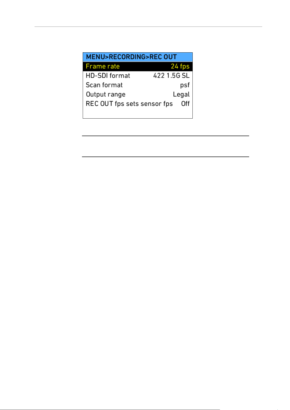
90 Camera Controls
REC OUT
Frame rate
Select to set the frame rate of the REC OUT
outputs (independent of sensor frame rate).
HD-SDI format
Select to set the format of the REC OUT
outputs (see below for details):
422 (1.5G DL, 3G SL, 3GDL)
444 (1.5G DL, 3G SL, 3GDL)
ARRIRAW (1.5G DL, 3G SL, 3GDL)
MON OUT clone
Scan format
Select to set the type of scan:
p: Progessive. Images are transmitted
line by line from left to right, starting at
the top-left pixel.
psf : Progressive segmented. Images
are first split into fields, which are then
transmitted line by line from left to right.
Note: Frame rates over 30 fps are only
available in progressive scan. This complies
with SMPTE standards.
Select the REC OUT submenu to adjust parameters for recording to external
recorders over the HD-SDI REC OUT outputs.
Note: Only use double shielded HD-SDI cables for recording to ensure error free data
transmission!
Page 91

Main Controls 91
Output range
Select to set which bit range of the full 10 bit
range (0-1023) is used to transmit image data.
Legal: Uses values 64-940 for RGB and
Y signals, and values 64-960 for CbCr
signals. This complies with SMPTE
274M 8.7.
Extended: uses values 5-1019, which
results in about 10% more steps. This
complies with SMPTE 274M 8.12 (called
undershoot/overshoot).
Note: Check which mode your recorder
supports. If you set the camera to extended,
but your recorder only supports legal, you will
end up with clipped images!
REC OUT fps sets
sensor fps
If set to "On", the sensor will always follow the
REC OUT frame rate setting. This ensures no
frames are dropped on the output.
Note: Both REC OUT and MON OUT carry a flag in their data stream to signal an
Format
Links
Used
Image
Raster
Sampling
Structure
Color
Mode
Possible
Frame Rates
(fps)
422
1.5G SL
1
1920x108
0
4:2:2
YCbCr
23.976, 24,
25, 29.97, 30
422
1.5G DL
2
1920x108
0
4:2:2
YCbCr
48, 50, 59.94,
60
422
3G SL
1
1920x108
0
4:2:2
YCbCr
48, 50, 59.94,
60
444
1.5G DL
2
1920x108
0
4:4:4
RGB
23.976, 24,
25, 29.97, 30
444
3G SL
2
1920x108
0
4:4:4
RGB
23.976, 24,
25, 29.97, 30
444
3G DL
1
2
1920x108
0
4:4:4
RGB
48, 50, 59.94,
60
ARRIRAW
1.5G DL
2
2
2880x162
0
Bayer
Bayer
23.976, 24,
25, 29.97, 30
external recorder that the camera has started or stopped recording internally. When
SxS recording is switched off, the REC button will only send the flag to trigger the
external recorder—it will not start or stop internal recording to SxS. Additionally, the
Vari flag marks duplicate images in the HD-SDI stream. A recorder that supports the
Vari flag can detect these frames and discard them. This ensures that no duplicate
frames are recorded if HD-SDI is set to a higher frame rate than the sensor.
HD-SDI formats and corresponding frame rates
Page 92

92 Camera Controls
ARRIRAW
3G SL
2
2
2880x162
0
Bayer
Bayer
23.976, 24,
25, 29.97, 30
ARRIRAW
3G DL
2
2
2880x162
0
Bayer
Bayer
48, 50, 59.94,
60
MON OUT
clone3
1
1920x108
0
4:2:2
YCbCr
23.976, 24,
25, 29.97, 30
1
Proprietary signal format, as no SMPTE standard supports RGB 444 with
frame rates higher than 30 fps. Only supported by some recorders.
2
The RAW sensor image is transmitted wrapped as 1920x1080 RGBA. This
signal can only be recorded with ARRIRAW T-Link certified recorders. Some
recorders only support certain types of ARRIRAW T-Link.
3
When in High Speed mode, REC OUT is always set to MON OUT clone.
30-60 fps recording with ALEXA over HD-SDI
Unlike the ARRIFLEX D-21, which used a proprietary mode for recording
frame rates between 30-60 fps, the ALEXA complies with the SMPTE 372M
standard for image transmission in 422 1.5G DL and 3G SL formats.
This means that images are split into fields, and every field is transmitted
over one link. The second field of every image is transmitted over the other
link, so that every link carries an interlaced signal in field integration mode.
The recorder realigns the images correctly into a progressive sequence.
Two proprietary formats allow transmission of 444 RGB or ARRIRAW
images at frame rates between 30-60 fps. These are 444 3G DL for RGB
and ARRIRAW 3G DL for raw images. These formats do not comply to a
SMPTE standard and are only supported by a few recorders. Please refer to
the manual of your recorder to see if it supports these formats.
12.1.5.2 Monitoring
Select the Monitoring submenu to adjust parameters for monitoring on the
EVF-1 and over the MON OUT output. These outputs are meant for
monitoring and not recording.
Page 93
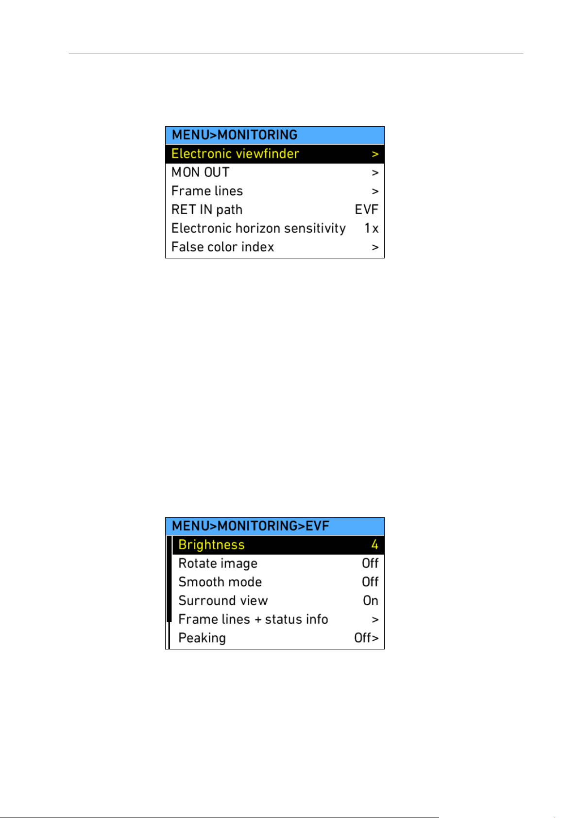
Main Controls 93
Frame lines set in the Frame lines submenu apply to both MON OUT and
Electronic viewfinder
Select to adjust EVF-1 settings.
MON OUT
Select to adjust MON OUT settings.
Frame lines
Select to set up frame lines.
RET IN path
Select to set which of the monitoring output paths
carries the signal at the RET IN connector as Return
in active is toggled via a USER button.
Electronic
horizon
sensitivity
Select to adjust the sensitivity of the electronic
horizon.
Note: Available on ALEXA Plus, ALEXA Plus 4:3,
ALEXA Studio and ALEXA M only
False color
index
Select to open the FALSE COLOR INDEX screen
which has a reference chart explaining the false color
coding for EVF and MON OUT.
Brightness
Select to adjust the brightness of the EVF.
EVF-1. Select the Electronic viewfinder and MON OUT submenus to switch
the set frame lines on or off individually.
Electronic Viewfinder
Page 94

94 Camera Controls
Rotate image
When mounting the EVF to the right side of the
camera, the image can be flipped to orient the image
correctly in the viewfinder. Affects only the EVF
image, MON OUT and recording images are not
rotated.
Smooth mode
Select to set Smooth mode On or Off. With smooth
mode on, the EVF image shutters less when panning.
Note: Smooth mode is only possible with frame rates
up to 30 fps and shutter angles of 180.0 or less.
Surround view
Select to set Surround view on the EVF-1 On or Off.
When set to on, the additional pixels outside the
recorded image area on the ALEXA’s ALEV III sensor
are displayed, allowing the operator to see outside
the recorded image and keep unwanted objects, such
as microphone booms, out of the shot. To view only
the recorded image, set Surround view to off.
Frame lines +
status info
Select to set frame lines, surround mask, center mark
and status info overlays to On or Off in the EVF.
Peaking
Select to set peaking in the EVF to On or Off, and the
strength of peaking to low, medium or high.
Anamorphic
desqueeze
Select to set Anamorphic desqueeze to 1.3x, 2.0x
and 2.0xmag. The desqueeze corrects the image for
1.3x and 2.0x anamorphic lenses. With 2.0x lenses,
the user can choose between viewing the full sensor
image (2.0x), or only the relevant image area
(2.0xmag) where left and right sides of the EVF-1
image outside the 2.39 aspect area are cropped.
Only available if a license for anamorphic desqueeze
is active in the camera.
Zoom position
Select to set the Zoom position to Centered or Eye
level. Press the ZOOM button on the EVF-1 to
magnify:
Centered – the center of the image is
magnified for focus check
Eye level – the image is magnified for focus
check along a line approximately one third from
the top, where an actor’s eyes are commonly
located in image composition.
Frame lines + status info screen
Frame lines
Select to set frame lines to On or Off. Frame lines are
a reference for framing that typically consist of an
image frame, a center mark and an aspect ratio
reference. See the appendix for more information on
the ALEXA frame line format.
Surround mask
Select to adjust the Surround mask settings. If
surround view is set to "On", it must be separated
from the recorded image area to allow proper
framing. Users can choose:
Page 95

Main Controls 95
Black line
Color line
Mask 25%
Mask 50%
Mask 100%
Center mark
Select to set the Center mark to Off, Dot or Cross to
aid in image framing.
Status info
Select to set Status info to On or Off. When set to On,
camera shooting parameters are displayed across
the top of the EVF-1’s image, outside the active
image area and camera status information is
displayed across the bottom of the EVF-1’s image,
outside the active image area.
Electronic
horizon
Select to set the electronic horizon level to On or Off.
Only available on ALEXA Plus, ALEXA Plus 4:3,
ALEXA Studio and ALEXA M.
LDS info
Overlay showing LDS lens info.
Only available on ALEXA Plus, ALEXA Plus 4:3,
ALEXA Studio and ALEXA M.
Frame rate
Select to set the MON OUT frame rate to 23.976, 24,
25, 29.97 or 30 fps. The frame rate should, if
possible, match the sensor frame rate to avoid
dropped frames or duplicate frames on the output,
which would result in jittery images during camera
movement or when image subjects are moving.
Scan format
Select to set the type of scan:
p: Progessive. Images are transmitted line by
line from left to right, starting at the top-left
pixel.
psf: Progressive segmented. Images are first
split into fields, which are then transmitted line
by line from left to right.
Surround view
Select to set Surround view on the MON OUT On or
Off. When set to on, the additional pixels outside the
recorded image area on the ALEXA’s ALEV III sensor
are displayed, allowing the operator to see outside
the recorded image and keep unwanted objects, such
as microphone booms, out of the shot. To view only
the recorded image, set Surround view to off.
Frame lines +
status info
Select to set frame lines, surround mask, center mark
and status info overlays to On or Off on the MON
OUT.
MON OUT
The MON OUT is a 422 1.5G single link HD-SDI output. The output range is
fixed at legal range.
Page 96

96 Camera Controls
Peaking
Select to set peaking on the MON OUT to On or Off,
and the strength of peaking to low, medium or high.
False color
Select to activate the false color display on the MON
OUT. The false color display is an exposure tool that
overlays the image with color coding to highlight
areas with significant luminance values.
Anamorphic
desqueeze
Select to set Anamorphic desqueeze to 1.3x, 2.0x
and 2.0xmag (only available if a license for
anamorphic desqueeze is active in the camera). The
desqueeze corrects the image for 1.3x and 2.0x
anamorphic lenses. With 2.0x lenses, the user can
choose between viewing the full sensor image (2.0x),
or only the relevant image area (2.0xmag) where left
and right sides of the MON OUT image outside the
2.39 aspect area are cropped.
Only available if a license for anamorphic desqueeze
is active in the camera.
Frame lines
Select to set frame lines to On or Off. Frame lines are
a reference for framing that typically consist of an
image frame, a center mark and an aspect ratio
reference. See the appendix for more information on
the ALEXA frame line format.
Surround mask
Select to adjust the Surround mask settings. If
surround view is set to "On", it must be separated
from the recorded image area to allow proper
framing. Users can choose:
Black line
Color line
Mask 25%
Mask 50%
Mask 100%
Center mark
Select to set the Center mark to Off, Dot or Cross to
aid in image framing.
Note: Only use double shielded HD-SDI cables for monitoring to ensure error free
data transmission!
Frame lines + status info screen
Page 97

Main Controls 97
Status info
Select to set Status info to On or Off. When set to On,
camera shooting parameters are displayed across
the top of the MON OUT image, outside the active
image area and camera status information is
displayed across the bottom of the MON OUT image,
outside the active image area.
Electronic
horizon
Select to set the electronic horizon level to On or Off.
Only available on ALEXA Plus, ALEXA Plus 4:3,
ALEXA Studio and ALEXA M.
LDS info
Select to set the LDS lens information overlay to On
or Off.
Only available on ALEXA Plus, ALEXA Plus 4:3,
ALEXA Studio and ALEXA M.
Show reel + clip
info
Select to display reel and clip numbers on the MON
OUT image.
Camera index
letter
Select to display the camera index letter in the top left
corner of the MON OUT image.
Frame Lines
Frame lines are an image overlay that can be applied to either the EVF
image, the MON OUT image, or both.
ALEXA frame lines are stored as XML files that define the frame lines’
aspect ratio, marker style, line width, center marker and more. The color of
the frame lines is set on the camera.
The following default frame lines are loaded onto the ALEXA:
1.33:1
1.66:1
1.78:1
1.85:1
2.39:1
2.39:1 2.0x anamorphic
Page 98

98 Camera Controls
Additional frame lines can be loaded from the SD card. To create additional
Frame line 1
Select to set the primary frame line template.
Frame line 2
Select to set a secondary frame line, if desired.
User rectangles
Select to open the User rectangles menu, where two
custom user rectangle overlays can be adjusted.
Color
Select to set the color of the frame lines. In the frame
lines definition file, lines can either be given a fixed
color, or they can have the color specified as "User".
If "User" is chosen for a line, the setting chosen in
this menu section is applied to the line.
Intensity
Select to set the intensity of the frame lines. The
higher the number, the brighter the frame lines
appear.
User rectangles
Select to set user rectangles to Off, Rect 1, Rect 2 or
Rect 1&2. The ALEXA can display up to two
additional rectangles that can be adjusted manually.
Set rect 1
Select to set the shape of rectangle 1. Activate it
through User rectangles.
Set rect 2
Select to set the shape of rectangle 2. Activate it
through User rectangles.
frame lines, use ALEXA Frameline Composer, a free web tool at
http://www.arri.com/camera/digital_cameras. Save the new frame lines as
XML files to an SD card formatted on the ALEXA, in the Frame lines folder.
The ALEXA supports up to 16 frame line templates.
To load additional frame lines:
1. In the FRAME LINES menu, select Frame line 1 (or Frame line 2).
2. Press the ADD button.
3. On the FRAME LINES (SD CARD) screen, use the jogwheel to select
the frame line you wish to add.
4. Press the jogwheel to add it to the FRAME LINES list.
5. Using the jogwheel, select the new frame line in the FRAME LINES list.
6. Press the jogwheel to set the new frame line.
User rectangles screen
Note: Default frame lines have "User" specified as color for all content.
Page 99

Main Controls 99
False Color Index
Sensor mode
Select to set which sensor mode is active, 4:3 or
16:9.
Note: Only on ALEXA Plus 4:3, ALEXA Studio and
ALEXA M.
SxS resolution
Select to set the current SxS recording resolution.
Links to MENU>Recording>SxS CARDS.
Codec
Select to set the current SxS recording codec. Links
to MENU>Recording>SxS CARDS.
Note: When SxS is switched off, the currently active
REC OUT format is shown.
Project fps
Select to set the timebase of the time code, which
determines how many frames the time code counts
per second and the frame rate of Quicktime clips
recorded to SxS PRO cards during playback.
Camera index
Select to set the camera indentifier. Identifies the
individual camera unit in clips and is reflected in clip
names on SxS PRO cards.
Next reel count
Select to set the reel number assigned to the next
new SxS PRO card used for recording. The ALEXA
automatically advances the reel number every time a
new SxS PRO card is formatted on the camera. The
reel number is reflected in clip names on SxS PRO
cards.
Production info
Select to open the PRODUCTION INFO screen
where the user can enter metadata information
specific to the production.
Select False color index to display a reference chart showing the relationship
between the color overlays, signal level in percent and descriptions. False
color is available on the EVF-1 and over the MON OUT outputs.
Figure 60: False Color Encoding
12.1.5.3 Project
Page 100

100 Camera Controls
Director
Enter the name of the director
Cinematographer
Enter the name of the cinematographer
Location
Enter the name of the location
Production
Enter the name of the production
Scene
Enter the name of the scene
Take
Enter the name of the take
User Info 1
Enter other info
User Info 2
Enter other info
Note: The user should set the value of the Next reel count to 001 at the beginning of
a shoot.
Production Info
The PRODUCTION INFO screen has fields to enter metadata information
specific to the production. The user can enter the names of the director,
cinematographer, location, production, scene and take. Two additional fields
allow to enter other data.
 Loading...