

Page 1

ALEXA Mini
ALEXA Mini
Software Update Packet 2.5
Software Update Packet 2.5
Q U I C K G U I D E
Q U I C K G U I D E
Date: 28 May 2015
Date: 28 May 2015
Page 2

2 Imprint
Imprint
Copyright
© 2015 Arnold & Richter Cine Technik GmbH & Co. Betriebs KG. All rights reserved.
No portions of this document may be reproduced without prior written consent of
Arnold & Richter Cine Technik GmbH & Co. Betriebs KG. Specifications are subject to
change without notice. Errors, omissions, and modifications excepted.
AMIRA, ALEXA, ALEXA XT, and ALEXA Mini are trademarks or registered trademarks
of Arnold & Richter Cine Technik GmbH & Co. Betriebs KG. All other brands or
products are trademarks or registered trademarks of their respective holders and
should be treated as such.
Original version.
NOTICE
This document is a Quick Guide only. For detailed operation instructions, please
refer to the User Manual.
For further assistance
Arnold & Richter Cine Technik GmbH & Co. Betriebs KG
Tuerkenstr. 89
D-80799 Munich, Germany
E-mail: service@arri.com
www.arri.com/service
Document revision history
Version
2.5
ID
K4.0006947
Release
K08771
Date
28.05.2015
Page 3

Contents 3
Contents
1
1.1
1.2
1.3
2 Audience and intended use................................................................. 9
3 Scope of delivery and warranty......................................................... 10
4 Camera layout......................................................................................11
4.1 Product identification........................................................................... 17
5 Power supply....................................................................................... 18
6 Switching on/off...................................................................................19
7 Connectors........................................................................................... 21
7.1 Front connectors..................................................................................21
7.2 I/O panel.............................................................................................. 22
7.3 Media panel......................................................................................... 24
For your safety / 为了您的安全..............................................................5
Risk levels and alert symbols / 危险级别和警示标志.............................5
Vital precautions / 重要安全措施........................................................... 6
General precautions / 般安全措施......................................................... 7
7.3.1 Preparing a USB memory stick...........................................................25
7.3.2 Changing a CFast 2.0 card.................................................................26
8 Lens mount/filters................................................................................28
8.1 ND filter module.................................................................................. 28
8.2 Changing a lens.................................................................................. 29
8.3 Lens control......................................................................................... 30
8.3.1 Manual iris adjustment........................................................................ 30
8.3.2 Iris control via user button...................................................................32
8.3.3 Auto iris................................................................................................33
9 Camera controls.................................................................................. 34
9.1 Function button FN and camera buttons 1-3...................................... 34
9.2 Recording button................................................................................. 36
10 MVF-1 controls.....................................................................................38
10.1 EVF image/monitor..............................................................................39
10.2 PK peaking button...............................................................................40
10.3 EXP exposure tool button................................................................... 41
10.4 VF1 & VF2 user buttons..................................................................... 42
10.5 PLAY button........................................................................................ 42
10.6 Diopter adjustment.............................................................................. 43
10.7 Adjusting the monitor...........................................................................43
Page 4

4 Contents
10.8 Changing the monitor mode................................................................44
10.9 Live monitor......................................................................................... 45
10.10 User monitor........................................................................................ 46
10.10.1 Status section...................................................................................... 49
10.10.2 Adjusting the monitor brightness.........................................................51
11 Web remote.......................................................................................... 52
12 Camera preparation.............................................................................54
12.1 Adjusting the MVF-1............................................................................54
12.2 Mounting to a bridge plate.................................................................. 55
13 Assembly and retrofits....................................................................... 58
13.1 MVF-1 and EVF cable.........................................................................58
13.2 Camera handle.................................................................................... 60
13.3 Antenna................................................................................................61
13.4 Changing a lens mount....................................................................... 62
14 Licensing.............................................................................................. 65
15 Appendix...............................................................................................66
15.1 Dimensions and weight (with titanium PL mount)............................... 66
15.2 Declarations of conformity................................................................... 67
Page 5
For your safety / 为了您的安全
1 For your safety / 为了您的安全
Before use, please ensure that all users comprehensively read, understand, and
follow the instructions in this document. / 使用前,请确保所有的用户都已经阅读、理
解,并遵循本文档内的操作说明。
1.1 Risk levels and alert symbols / 危险级别和警示标志
Safety warnings, safety alert symbols, and signal words in these instructions indicate
different risk levels:
DANGER!
DANGER indicates an imminent hazardous situation which, if not avoided, will
result in death or serious injury.
5
WARNING!
WARNING indicates a potentially hazardous situation which, if not avoided, may
result in death or serious injury.
CAUTION!
CAUTION indicates a potentially hazardous situation which, if not avoided, may
result in minor or moderate injury.
NOTICE
NOTICE explains practices not related to physical injury. No safety alert symbol
appears with this signal word.
Note: Provides additional information to clarify or simplify a procedure.
本文档内的安全警告、安全警示标志和标识词语指示不同的危险级别:
危险
危险表示危急、有危害的情景,若不防范,则会导致死亡或严重的伤害。
警告
警告表示有潜在危害的情景,若不防范,则可能会导致死亡或严重的伤害。
小心
小心表示有潜在危害的情景,若不防范,则可能会导致中等或较轻的伤害。
提示
注意表示此行为不会导致人身伤害。因此此标识词语中不含警告标志。
注:注意中会提供用于解释或简化工作的额外信息。
Page 6
6
1.2 Vital precautions / 重要安全措施
High voltage! Risk of electric shock and fire!
Short-circuits may entail lethal damage!
Before use, read and follow all valid instructions.
Use solely and exclusively as described in the instructions.
Never open. Never insert objects.
For operation, always use a power source as indicated in the instructions.
Always unplug the power cable by gripping the power plug, not the cable.
Never try to repair. All repair work should be done by a qualified ARRI Service
Center.
Never remove or deactivate any safety equipment (incl. warning stickers or paintmarked screws).
Always protect from moisture, cold, heat, dirt, vibration, shock, or aggressive
substances.
Never cover any fan openings.
For your safety / 为了您的安全
WARNING!
危险
高电压!有触电或起火风险!
短路将引起致命危险。
使用之前,请仔细阅读所有未过期的使用说明,并严格遵循。
切勿打开机身。切入插入任何物体。
操作时,请务必使用说明中指出的电源。
断开电源时请握住电源插头,而不是电线。
切勿尝试自行维修。所有的维修工作必须由具备资质的ARRI 维修中心进行。
切勿移除或毁坏任何安全设施(例如警告贴纸或涂漆标示的螺丝)。
务必避免潮湿、寒冷、炎热、多尘、震动、冲击或严酷的使用环境。
切勿覆盖任何风扇开口。
Page 7
For your safety / 为了您的安全
Condensation! Risk of electric shock and fire!
Condensation may form on the sensor and electrical connections when exposing
the camera to sudden changes of temperature or humidity!
To avoid injury and damage, never operate the camera when condensation occurs.
冷凝!有触电或火灾风险!
当将摄影机暴露于温度或湿度迅速变化的环境中时,影像传感器和电子部件连接处可
能会产 为了您的安全 6 生的冷凝。
为了避免受伤或设备损坏,在冷凝发生时切勿操作摄影机。
Heavy weight! Risk of injury and damage!
If placed on an unstable surface, the camera can fall and cause serious harm!
Always place the camera on proper support devices. Safely attach it as described
in the instructions.
7
CAUTION!
小心
CAUTION!
小心
设备重量较大!有受伤或设备损坏风险!
若安置于不稳定的位置,则摄影机可能会掉落,并造成严重的伤害。
务必将摄影机安装于适当的支撑设备上。请按照说明中所描述的方法来安全地安装摄
影机。
CAUTION!
Hot surfaces! Risk of injury and damage!
During extended operation or operation in high ambient temperatures, the fan outlet
at the camera rear, the CFast drive and the CFast card can get hot.
Never cover, obstruct or block the fan in- or outlets while the camera is powered.
1.3 General precautions / 般安全措施
NOTICE
Even rugged cameras use components sensitive to improper use.
Always unplug the camera from power sources before making changes to the setup
or system (in particular: changing cables).
Direct sunlight can result in camera housing temperatures above 60 °C (140 °F). At
ambient temperatures above 25 °C (77 °F), protect the camera from direct sunlight.
Protect the optical system and sensor: Never point the camera or viewfinder into
direct sunlight.
Avoid permanent sensor damage: Never let any direct light or reflections from highenergy light sources (e.g. laser beams) enter the camera's optical path.
Protect the sensor: Always keep a lens or protective cap on the empty lens mount.
Change lenses in dry, dust-free environments only.
Always clean the sensor cover glass according to ARRI instructions.
Only use the tools, materials and procedures recommended in this document. For
the correct use of other equipment, see the manufacturer's instructions.
Page 8

8
For your safety / 为了您的安全
提示
即使本摄影机非常坚固,也是由敏感的组件所组成的,请谨慎使用。
当改变摄影机安装支撑设备或系统时(特别是更换电缆),请务必断开摄影机电源。
注意保护光学系统和影像传感器:切勿将摄影机或取景器直接面朝直射阳光。
避免对影像传感器造成永久性伤害:切勿让任何来自高能量光源(例如激光)的直射
光或反 射光进入摄影机的光路系统。
注意保护影像影像传感器:空镜头卡口上务必安装镜头或保护盖。更换镜头时,务必
在干燥、 无尘的环境中进行。
请完全并仅按照用户手册中所描述的方法来清洁影像传感器保护玻璃。若清洁不成
功,请咨 询ARRI 维修中心。切勿尝试打开保护玻璃。
清洁影像传感器保护玻璃时,务必遵守ARRI说明书中描述的方法。
仅使用本文档中建议使用的工具、材料和操作方法。若要正确地使用其他设备,请参
阅其制 造商的说明书。
Page 9

Audience and intended use 9
2 Audience and intended use
NOTICE
The product is solely and exclusively available for commercial costumers and shall
be used by skilled personnel only. Every user should be trained according to ARRI
guidelines.
Use the product only for the purpose described in this document. Always follow the
valid instructions and system requirements for all equipment involved.
The ALEXA Mini is a 35 mm digital camera solely and exclusively for recording
images at various resolutions suitable for a variety of distribution formats:
ProRes 422, ProRes 422 HQ, ProRes 4444, ProRes 4444HQ, and RAW*
•
codecs
REC 709 encoding (through use of look files), Log C or RAW* encoding
•
CFast 2.0 card recording
•
Up to 200 fps with full image quality
•
35 mm CMOS sensor in 16:9 or 4:3* modes
•
Small and lightweight built for high mobility and special applications
•
* Not supported upon initial release. For SUPs beyond 2.5, please check the cor-
responding release notes.
Page 10

10 Scope of delivery and warranty
3 Scope of delivery and warranty
NOTICE
Product and packaging contain recyclable materials. Always store, ship, and
dispose of according to local regulations.
ARRI is not liable for consequences from inadequate storage, shipment or disposal.
Delivery
On delivery, please check if package and content are intact. Never accept a damaged/
incomplete delivery. A complete delivery includes:
ALEXA Mini camera with lens mount according to order: titanium PL, AMIRA
•
PL, EF
Antenna
•
USB memory stick
•
3 mm Allen key
•
Quick Guide
•
Original packaging incl. drying agent
•
NOTICE
ARRI offers an increasing variety of product bundles and additional accessories.
For details, please consult our website or your local ARRI Service Partner.
Warranty
For scope of warranty, please ask your local ARRI Service Partner. ARRI is not liable
for consequences from inadequate shipment, improper use, or third-party products.
Page 11
Camera layout 11
1
2
3
4
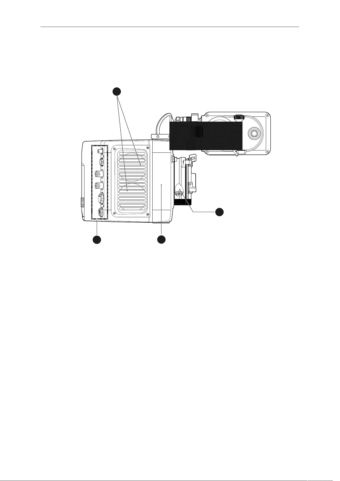
4 Camera layout
Right
1 Fan intake
2 LBUS connector
3 integrated WiFi antenna
4 I/O panel
Page 12
12 Camera layout
REC
FN
1
2
3
2
1
3
4
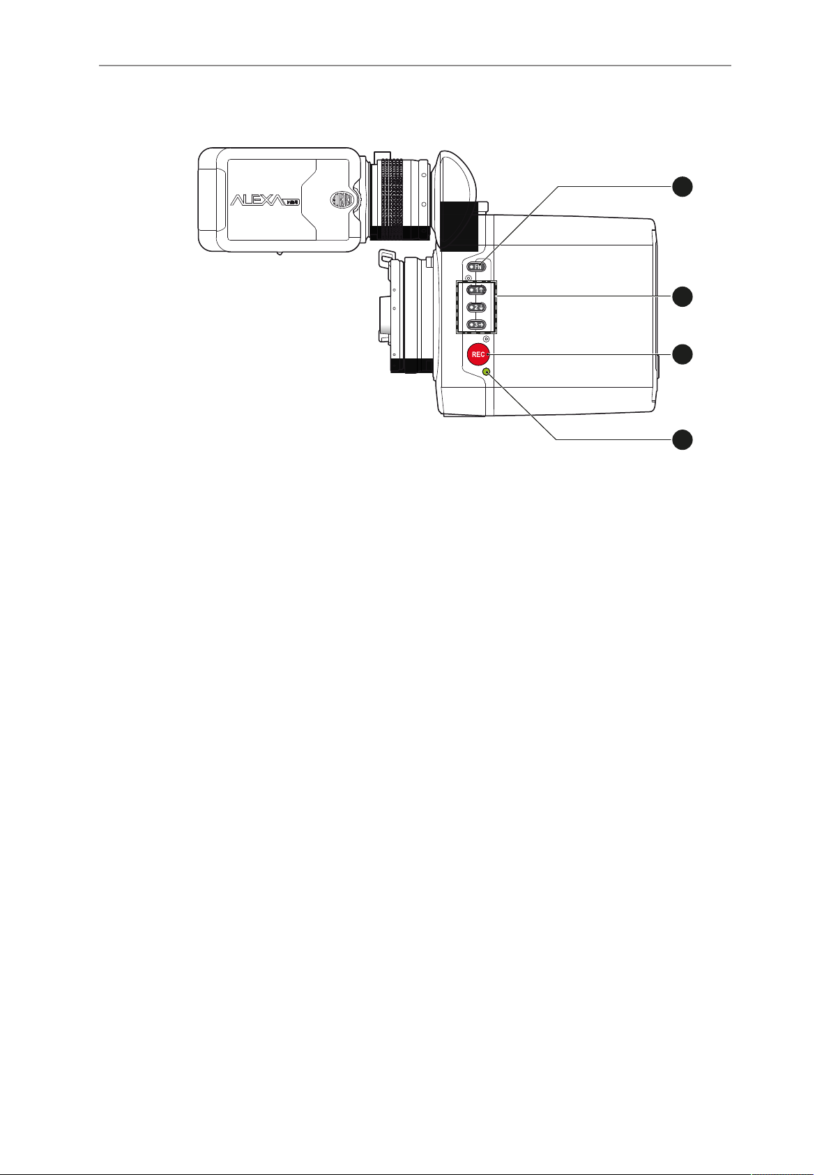
Left
1 Function button
2 Camera buttons 1-3
3 Recording button
4 Status LED
Page 13
Camera layout 13
REC
M
VF2
VF1
EXP
PK
1
2
3
4
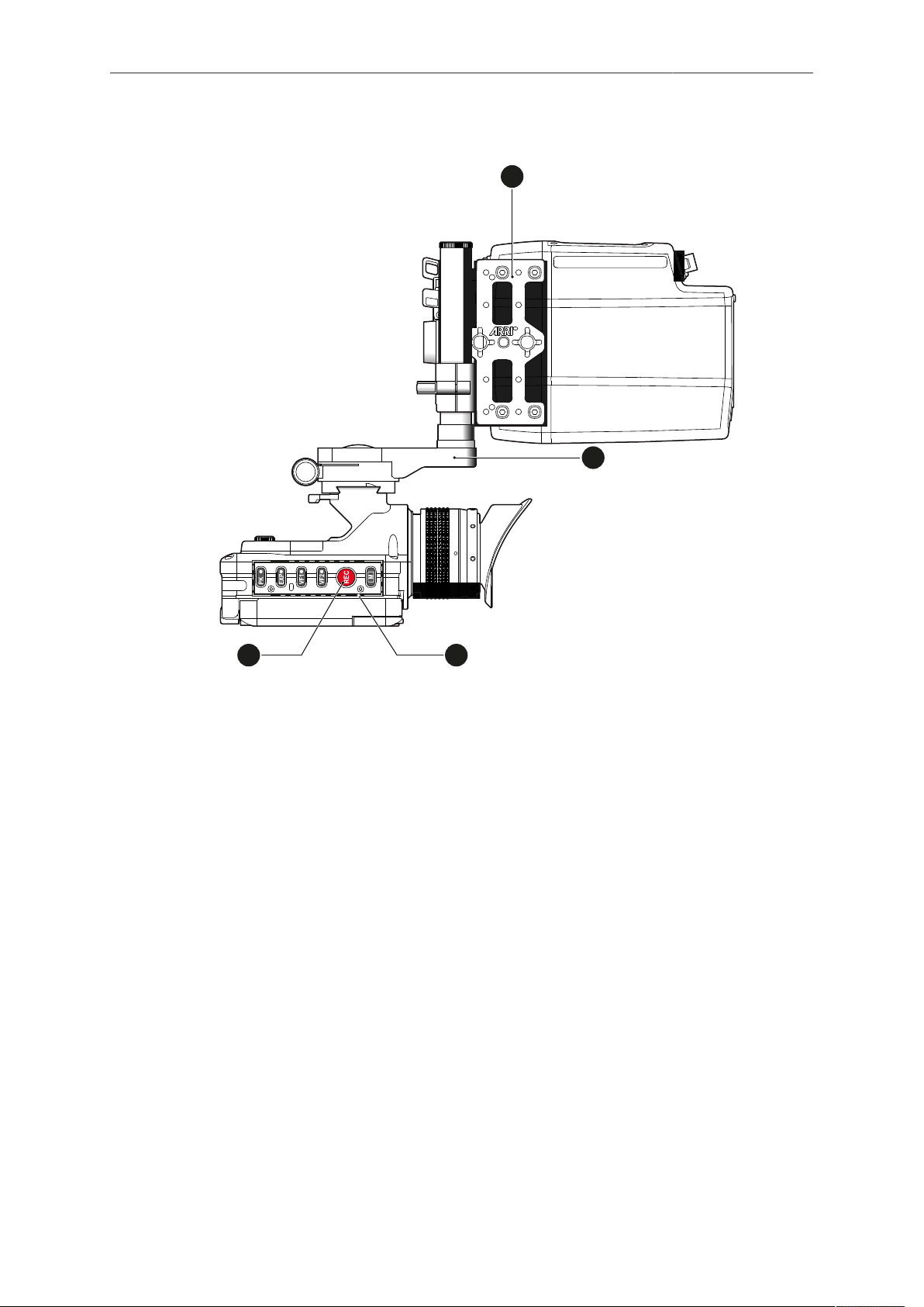
Top
1 MAP-1
2 MVB-1
3 MVF-1 buttons
4 Record button
Page 14
14 Camera layout
1
2
3
4
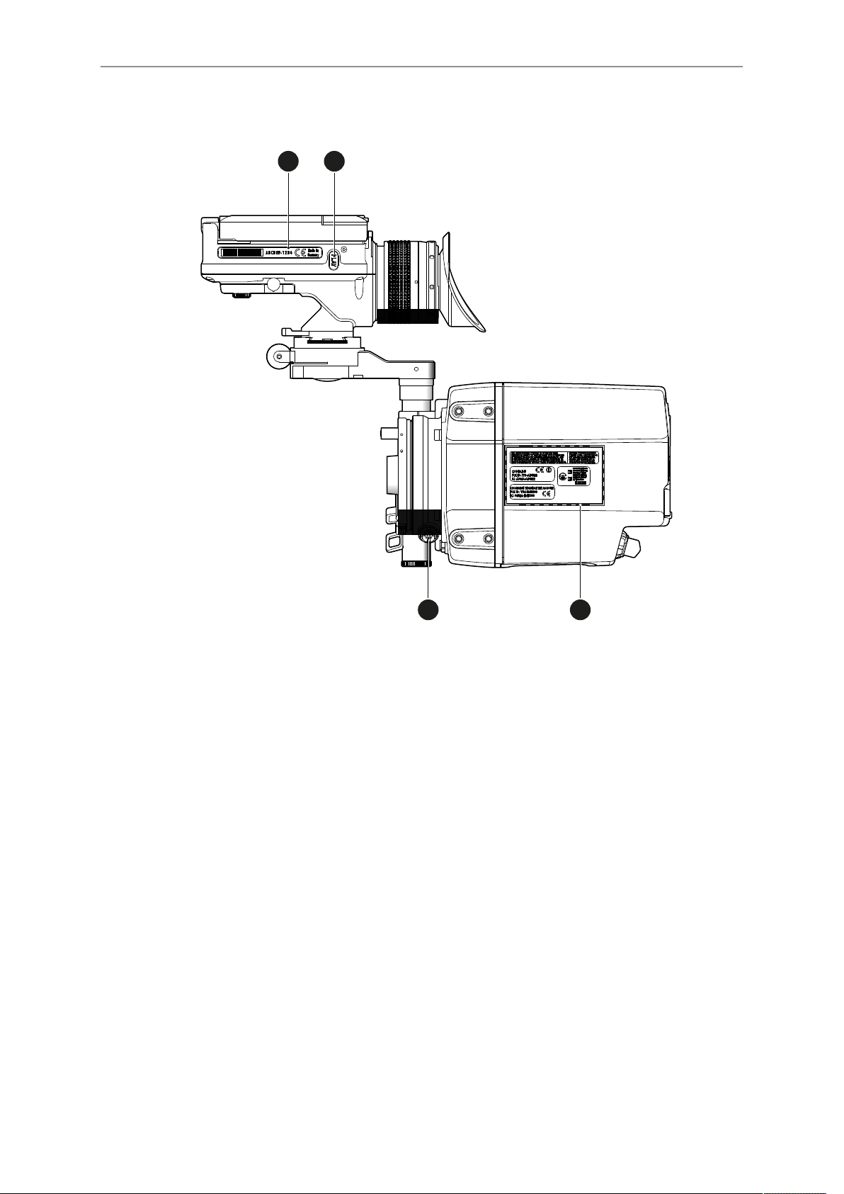
Bottom
1 MVF-1 type label
2 PLAY button
3 Camera type labels
4 LBUS connector
Page 15
Camera layout 15
1
2
3
4
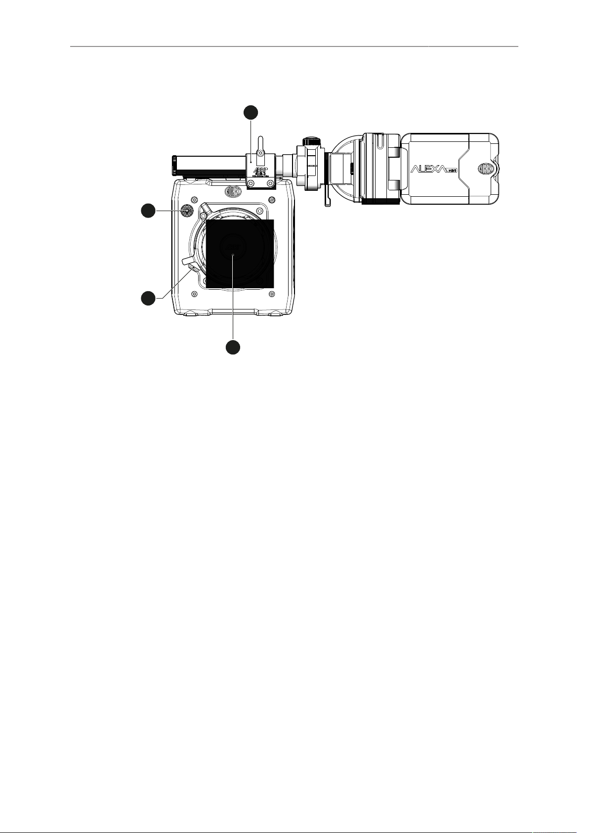
Front
1 RMB-3
2 Lens mount (here: PL)
3 LBUS connector
4 Audio connector
Page 16
16 Camera layout
1
2
3
8
9
1
0
1
1
4
5
6
7
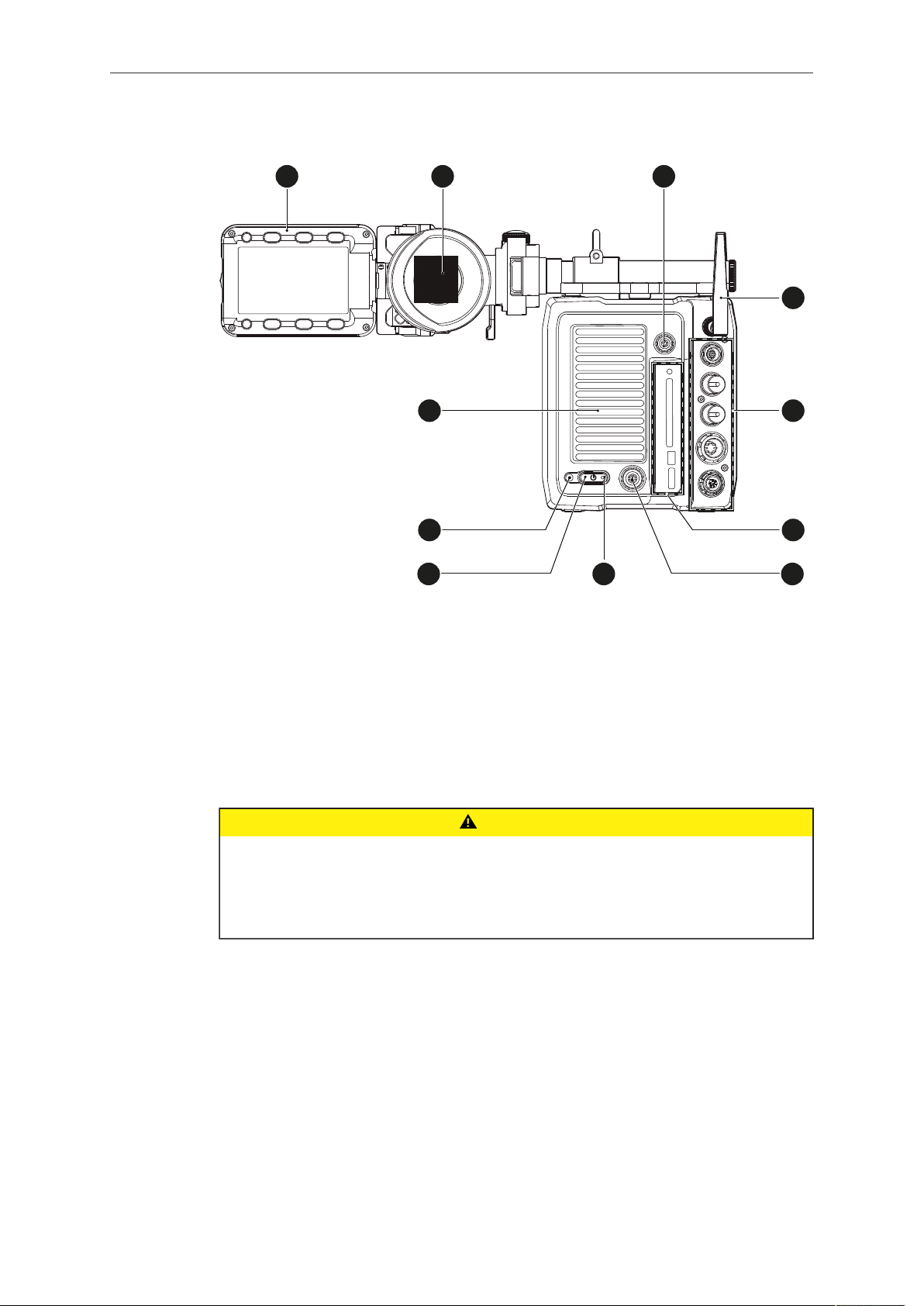
Back
1 Fold-away monitor (MVF-1)
2 OLED eyepiece
3 Timecode connector
4 White radio antenna
5 I/O panel
6 Media panel (CFast 2.0 card slot, USB)
7 Ethernet connector
8 Boot status LED
9 Power button
10 Recording status LED
11 Fan outlet
CAUTION!
Hot surfaces! Risk of injury and damage!
During extended operation or operation in high ambient temperatures, the fan outlet
at the camera rear, the CFast drive and the CFast card can get hot.
Never cover, obstruct or block the fan in- or outlets while the camera is powered.
Page 17
Camera layout 17
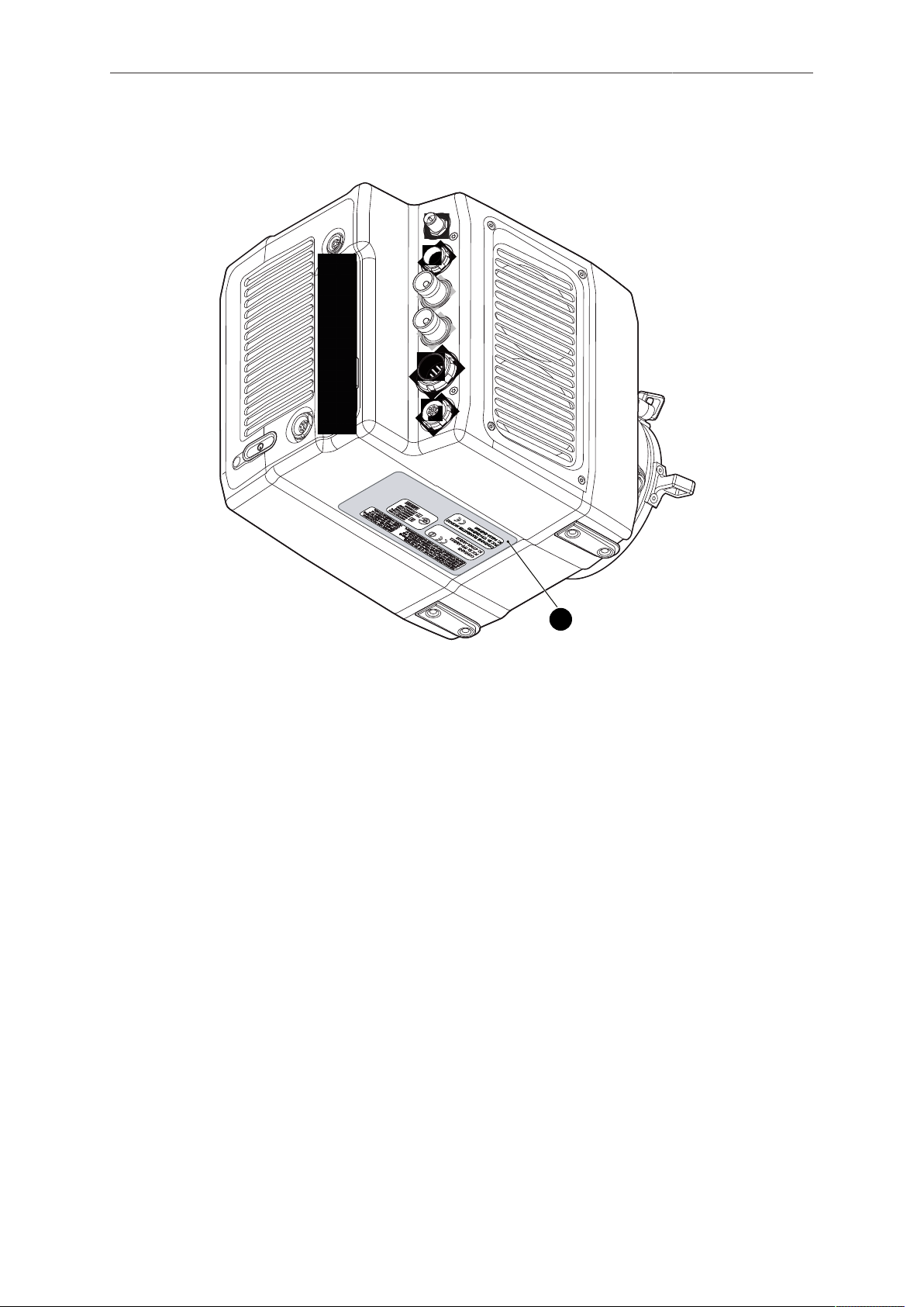
1
4.1 Product identification
The FCC conformity label and the CE type label with serial number (1) are on the
camera bottom.
Page 18

18 Power supply
5 Power supply
The camera power is supplied by external power sources only.
NOTICE
If the power supply is interrupted with the camera switched on, the camera will
automatically repower and boot-up on reconnection.
Use the 8-pin LEMO connector and a KC50-S or KC50-SP-S cable to supply the camera with 10.5 to 34 V DC.
Page 19
Switching on/off 19
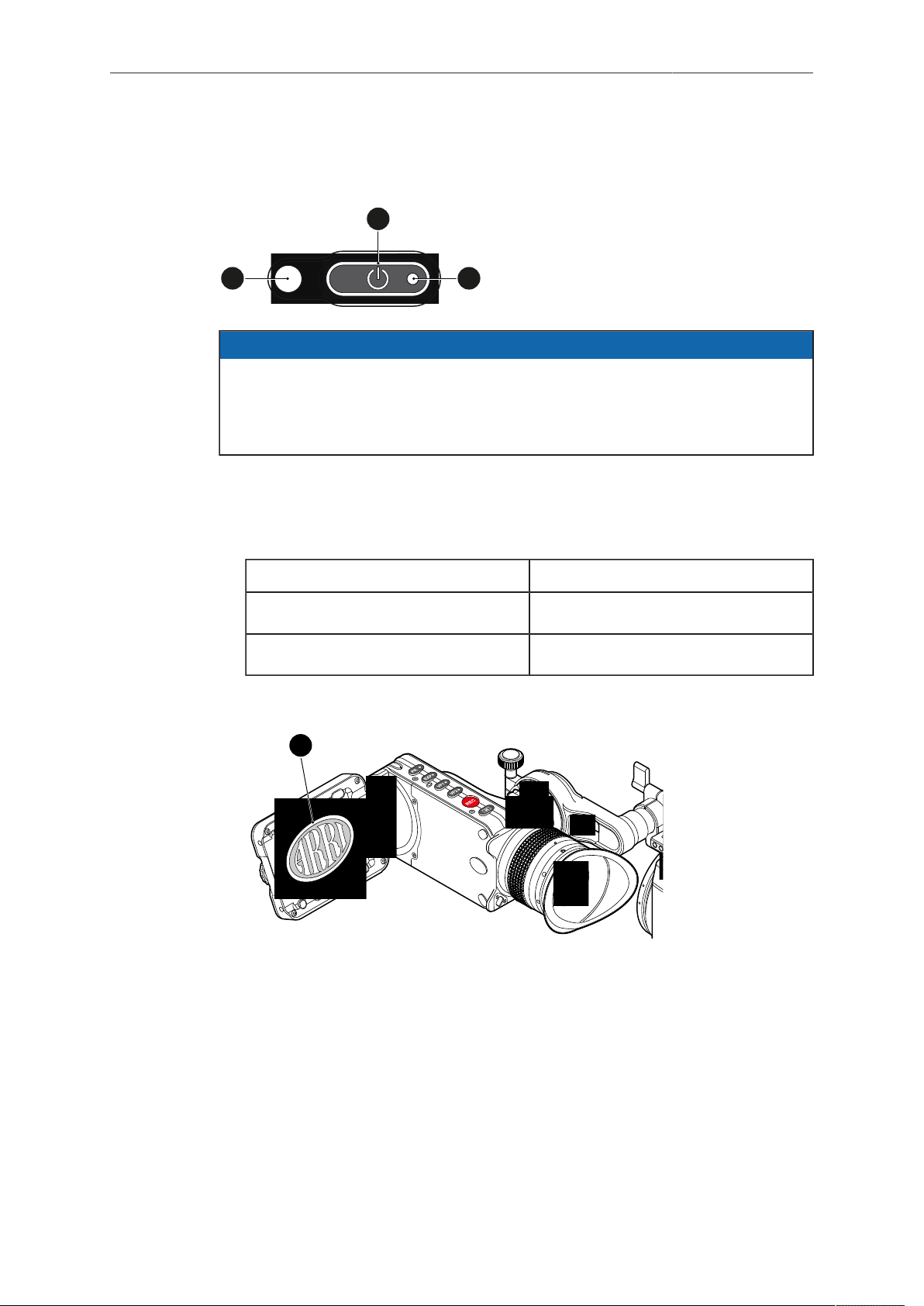
1
2
3
4
6 Switching on/off
NOTICE
Before switching on, ensure that the camera is connected to an external power
source.
The power button background illumination is on when the power is in the valid
range.
To switch on the camera:
► Press the power button (1).
The camera starts booting. The boot status is indicated as follows:
Boot status LED (2) is... Camera
flashing blue is booting
solid blue has finished the boot process
For mounted MVF-1 only: During the boot process, the ARRI logo appears in the
monitor of the MVF-1 (4).
To switch off the camera:
► Press and hold the power button (1) until the camera has switched off and the boot
status LED (2) turns off.
For mounted MVF-1 only: On the monitor of the MVF-1, a countdown appears.
On reaching zero, the camera switches off.
Page 20

20 Switching on/off
To check the recording status
The recording statuses are indicated as follows:
Record status LED (3) is... Camera is...
solid green ready for recording
solid red recording
off not ready for recording. Check, if
the CFast 2.0 card is valid. If not:
Insert a valid CFast 2.0 card. See
page 54.
flashing green/red alternately not ready for recording due to an er-
ror. Reboot camera.
NOTICE
The recording statuses are also visible in the home screen, the live screen, the
EVF image, and the SDI image.
Page 21
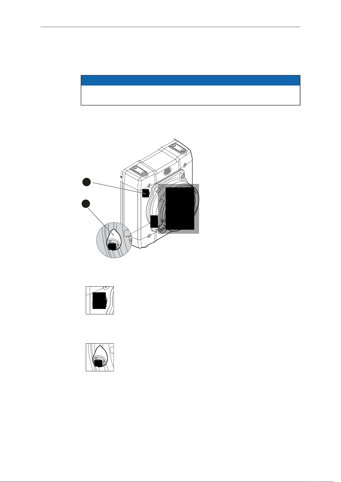
Connectors 21
1
2
7 Connectors
NOTICE
Connecting or disconnecting devices or cables while recording can disturb the
audio/image signal due to static electricity.
7.1 Front connectors
1 Audio in
2 L-Bus
Audio in (5-pin LEMO)
2-channel line level audio input.
LBUS (4-pin LEMO)
LBUS output for daisy-chainable active lens motors.
Page 22

22 Connectors
1
3
2
4
5
6
7
7.2 I/O panel
NOTICE
If the power supply is interrupted with the camera switched on, the camera will
automatically repower and boot-up on reconnection.
1 Timecode connector 5 BAT main power in
2 White radio antenna 6 EXT connector
3 MVF-1 7 Ethernet connector
4 HD-SDI image out 1 & 2
TC (5-pin LEMO)
The TC connector is a 5-pin LEMO socket. It accepts and distributes LTC (Longitudinal Time Code) signals.
White radio antenna
Mounting point for white radio antenna for lens control.
Page 23

Connectors 23
NOTICE
Do not leave the antenna connector open during operation or transport. The radio
module inside could be damaged by electrostatic discharge on the open connector.
ARRI recommends using the originally supplied antenna only (order number:
K2.0001996).
EVF (16-Pin LEMO)
Hot swappable interface for MVF-1.
SDI OUT 1 & 2 (BNC)
Both BNC outputs deliver image outputs in 1920 x 1080 422
1.5G, 422 3G, 444 3G and 422 6G* single link formats. Through
a hardware modification, SDI 2 can be reconfigured into an
SYNC/RET IN connector. Please contact an ARRI camera service center for more information.
*Only on SDI 2 in UHD recording format
BAT (8-pin LEMO)
Via cables KC50-S (2 m, straight) and KC50-SP-S (coiled), this
main power supply input accepts 10.5 to 34 V DC.
EXT (7-pin LEMO)
A connector for external accessories, carrying two CAN buses and accessory power output at camera voltage level (1.0 A
max.). With an external adapter, R/S functionality is supported.
ETH (10-pin LEMO)
Standard Ethernet connectors don't deliver the durability and reliability required by ARRI, so ALEXA Mini uses a 10-pin LEMO
connector. A special cable, available from ARRI (model KC-153S), is required to connect the Ethernet connector to a standard
RJ-45 Ethernet connector.
Page 24

24 Connectors
1
2
3
4
7.3 Media panel
1 Status LED 3 USB
2 CFast 2.0 card slot 4 Lid
Card (CFast 2.0)
Storage media slot for CFast 2.0 recording cards.
USB
Interface for USB memory sticks with FAT file system. Can also
be used to charge USB devices.
Page 25

Connectors 25
2
3
1
7.3.1 Preparing a USB memory stick
USB memory sticks for the ALEXA Mini must have a specific folder structure which
can be created with the camera.
1. To prepare a USB memory stick: Open the media lid (1).
2. Connect a FAT-formatted USB stick (3) to the camera (2).
3. From the home screen, navigate to Menu > Media > Prepare USB medium.
4. Press CONFIRM to prepare the folder structure.
5. The USB stick (3) is now ready for use with the camera.
6. Note: To avoid file corruption, never remove the USB stick during write access.
7. You can remove the stick from the camera without unmounting.
Page 26

26 Connectors
2
1
3
7.3.2 Changing a CFast 2.0 card
NOTICE
ALEXA Mini does not accept ALEXA-formatted CFAST 2.0 cards, and vice versa.
Before using a CFAST 2.0 card with ALEXA Mini, you must erase it in-camera to
create the required file system
Avoid damage to the contacts of both camera and card. Always insert cards as
described in this document.
Never change memory cards when recording - this may damage the recorded clip.
1. Open the lid (1).
2. Align the card's positive edge (3) facing the camera rear.
3. With the contact pins first, gently insert the card, until it audibly locks (2).
4. Gently close the lid (1). Never force it closed on an unlocked card.
Page 27

Connectors 27
2
1
5. For card removal: Open the lid (1).
6. Push the card in until it audibly unlocks (2).
7. Remove the card.
Page 28

28 Lens mount/filters
1
8 Lens mount/filters
1 Lens mount (here: PL)
8.1 ND filter module
The camera contains an internal ND filter module, consisting of ND 0, 0.6, 1.2 and 2.1
filters. The filters can be operated via user buttons or the MVF-1.
Page 29

Lens mount/filters 29
1
2
8.2 Changing a lens
NOTICE
Protect the sensor: Always keep a lens or protective cap on the empty lens mount.
Change lenses in dry, dust-free environments only.
Never exceed the maximum lens dimensions.
Have every lens properly shimmed as prescribed by the manufacturer.
PL mount
Note: Please use a lens support system for EF lenses above 3 kg/6.6 lbs.
1. Observe maximum lens dimensions (see User Manual).
2. Unlock the lens mount counter-clockwise (1) and remove the lens or cap.
3. Never touch the sensor.
4. Either: Mount the next lens and lock (2) the lens mount clockwise.
5. Or: Always cap and lock (2) an empty lens mount clockwise.
Page 30

30 Lens mount/filters
3
4
5
1
2
EF mount
Note: Please use a lens support system for EF lenses above 3 kg/6.6 lbs.
1. Observe maximum lens dimensions.
2. Turn the lever counter-clockwise (1) to unlock the mount.
3. Either: Remove the cap.
4. Or: Press and hold the button (2) to unlock the lens.
5. Turn the lens (3) counter-clockwise, then remove it.
6. Never touch the sensor.
7. Either: Mount the next lens:
Align the dots of both lens and lens mount.
°
Push the lens into the mount.
°
Turn the lens clockwise (5) until the bayonet locks.
°
Turn the lever clockwise (4) to tighten the lens to the lens mount.
°
8. Or: Always cap the empty lens mount.
8.3 Lens control
Control of lens iris is possible with ENG PL mount and EF lenses. You can control the
iris manually, via user button, or via auto iris.
8.3.1 Manual iris adjustment
HOME > EI > IRIS
Page 31

Lens mount/filters 31
1
2
2
1
1
2
Pressing the wheel (1) changes the step size between full and sub-stops (2). Note:
Sub-stop precision depends on the lens type and is automatically set by the camera.
On the live screen, you can activate and deactivate iris adjustment (1) by shortpressing the lower round (not oval!) button (2). Keeping the button pressed (2)
activates iris adjustment until it is released. (2). Note: Depending on the image flip, the
round buttons may appear on the right.
Pressing the wheel (1) changes the step size between full and sub-stops (2). Note:
Sub-stop precision depends on the lens type and is automatically set by the camera.
Page 32

32 Lens mount/filters
8.3.2 Iris control via user button
MENU > User button > Button X
For iris control, assign one user button each with Open Iris and Close Iris. See "MENU
> User buttons".
Page 33

Lens mount/filters 33
1
8.3.3 Auto iris
HOME > EI > IRIS > OPTIONS
Via jogwheel (1), you can define the auto iris behavior.
Auto iris mode: Defines the iris calculation:
Integral: Iris is calculated based on full image content.
•
Center: Iris is calculated with higher priority on image center.
•
Auto iris offset: Corrects the auto iris calculation result by up to +/- 3 stops in 1/3 stop
step sizes. Activate via user button.
Page 34

34 Camera controls
REC
FN
1
2
3
REC
FN
1
2
3
1
2
4
3
REC
FN
1
2
3
REC
FN
1
2
3
1
2
9 Camera controls
1 Function button with status LED
2 Camera buttons 1-3 with status LEDs
3 Recording button
4 Recording status LED
9.1 Function button FN and camera buttons 1-3
Camera buttons as user buttons:
By default, the camera buttons 1-3 function as user buttons.
1. In the camera menu (MENU > Camera user buttons), set the desired functions to
the user buttons.
The functions are assigned to the user buttons.
2. Press a user button (2) to trigger its function.
Depending on the assigned user button function, the LED reflects the function
state.
Page 35

Camera controls 35
Camera buttons to control standard camera functions:
► Press and hold the function button (1); then press a camera button (2). If a
simultaneous press cannot be performed, the FN button can be pressed twice
within 0.5 seconds to bring the camera buttons into function selection mode for 2
seconds. During these two seconds, pressing a camera button will de-/activate its
assigned function.
The LED of the FN button reflects that a standard function is active. An LED on
each button reflects the functional status.
The following standard functions can be triggered:
Function button &
camera button
1 Toggles the overlay menu of the Live view. In the
2 n.a.
3 Starts/stops the playback. During playback, the cam-
Function
overlay menu, the camera buttons control the following functions:
User button Function
1 Select Backward
2 Select Forward
3 Confirm
era buttons control the following functions:
User button Function
1 Skip Backward
2 Skip Forward
3 Play/Pause
Page 36

36 Camera controls
REC
FN
1
2
3
REC
FN
1
2
3
1
2
9.2 Recording button
NOTICE
Pressing a recording button returns the user interface to the home screen and
disables the menu access.
Recording also disables the US switch and the home screen buttons for FPS, TC,
Shutter, and Look settings.
To start recording:
Prerequisite: The camera is prepared.
1. Preset all buttons.
2. Press REC (1) on the left camera side.
The camera starts recording. The recording status LED (2) reflects the recording
status:
Recording status
LED (2) is...
solid green ready for recording
solid red recording
flashing red Recording starts/stops
off not ready for recording. Check if the CFast 2.0 card
flashing green/red
alternaterly
Camera is...
is valid. If not: Insert a valid CFast 2.0 card. See
page 54.
not ready for recording due to an error.
Page 37

Camera controls 37
1
3. For mounted MVF-1 only: Press REC (1) on the MVF-1:
NOTICE
Never change memory cards when recording - this may damage the recorded clip.
NOTICE
Connecting or disconnecting devices or cables while recording can disturb the
audio/image signal due to static electricity.
Page 38

38 MVF-1 controls
1
3
2
4
5 6
7
9
8
1
0
1
1
10 MVF-1 controls
1 Monitor (Live & GUI) 7 Monitor button
2 Peaking button 8 Proximity sensor
3 Exposure tool button 9 Diopter control
4 VF-1 user button 10 Screen buttons
5 VF-2 user button 11 Jogwheel
6 Recording button
Proximity sensor
This infrared sensor automatically deactivates the MVF-1's internal OLED panel when
you withdraw your eye. The sensor is placed either on the bottom left-hand side of the
viewfinder (Generation 1), or it is integrated in the eye cup (Generation 2).
The Alexa Mini MVF-1 contains the generation 2 proximity sensor.
NOTICE
To avoid hardware damage, always keep the sensor unobstructed.
Page 39

MVF-1 controls 39
1
2
3
1
2
3
4 5
6
7
8
9
10
11
12
13
14
15
16
17
18
10.1 EVF image/monitor
When you look through the eyepiece, the proximity sensor (3) activates the EVF
display (2).
You can add status data from the home screen (1) to the MVF-1 image (2).
If activated, overlays around the EVF image show essential camera, audio, and
recording statuses.
You can modify/deactivate these status bars via the EVF overlays and EVF status
components menu. For more details, see the User manual.
Note: In Overlay mode (see below), all status bars appear on the active MVF-1
image.
1 Sensor FPS 10 Camera status
2 SHUTTER value 11 Reel and clip info
3 TC Timecode (if enabled) 12 BAT level/status
4 EI Exposure index 13 Alert and temperature status
5 Internal ND filter 14 Camera settings icon (Rec format, Rec
6 WB White balance 15 EVF image status (EVF gamma, EVF
7 Icons for USB status, lens motor calibration
8 Audio status 17 Framelines
9 CARD capacity/status 18 Center mark (here: cross)
request, WiFi status
gamma, Iris, Fan status, Framegrab, Camera
lock)
exposure tool, EVF peaking)
16 LDS info
Page 40

40 MVF-1 controls
1
2
1
3
1 Safe mode
In Safe mode, all status bars appear in a black frame (1) outside the active MVF-1
image.
Note: If surround view is active, the area is marked by a surround mask.
10.2 PK peaking button
1. To activate peaking on monitor (1) and MVF-1 (3): Press PK (2).
2. Peaking highlights the image parts that are in focus for better focus judgement.
3. For PK settings: Go to MENU > Monitoring > EVF/Monitor > Peaking.
Page 41

MVF-1 controls 41
2
1
3
10.3 EXP exposure tool button
The EXP button (2) activates the set exposure tool on the monitor (1) and EVF image
(3). Use the tool for evaluation of the image exposure levels. An activated tool lights
up the button (2).
For EXP setting: Go to MENU > Monitoring > EVF/Monitor > Exposure tool.
In Zebra mode, the tool overlays up to two luminance ranges with diagonal stripes.
High zebra ranges above, Mid zebra around the user-defined luminance value.
False color mode overlays predefined luminance ranges as follows:
Luminance range
White clipping
Just below white clipping
One stop over medium gray (Caucasian skin)
18 % medium gray
Just above black clipping
Black clipping
Signal level
100 to 99 %
99 to 97 %
56 to 52 %
42 to 38 %
4.0 to 2.5 %
2.5 to 0.0 %
Color
Red
Yellow
Pink
Green
Blue
Purple
Page 42

42 MVF-1 controls
1
10.4 VF1 & VF2 user buttons
► Via the camera menu, you can assign a function to both VF-1 and VF-2 buttons
(1). For details, see the user manual.
10.5 PLAY button
1. Press PLAY (1) for one second to see the last clip of the active CFast 2.0 card.
2. To leave playback: Press PLAY (1) for one second.
3. Or: Press the EXIT screen button.
4. To select other clips, use the on-screen navigation. For details, see the User
Manual.
Page 43

MVF-1 controls 43
1
1
2
3
10.6 Diopter adjustment
► Twist the ring left or right for diopter adjustment (1).
10.7 Adjusting the monitor
► Fold (1), swivel (2) and flip (3) the monitor according to your needs.
Page 44

44 MVF-1 controls
1
1
1
2
3
3
10.8 Changing the monitor mode
1. To change the monitor mode between live view and user interface: Press M (1).
2. In live mode, toggle the status bar content (1) via the lower buttons.
3. Via the camera menu, you can activate a location sensor that automatically flips
the user interface to match a left- or right-sided monitor position (3).
4. Note: the jogwheel (1) and the screen buttons (2).
Page 45

MVF-1 controls 45
3
2
1
5
6
7
8
9
1
4
0
10.9 Live monitor
Below the camera live image, the live screen shows image and camera status. You
can toggle the bar's content via the left or right oval button below. The center oval
button returns you to the main status bar.
Note: The following status bar signals a standby camera with a 25.000 fps sensor
rate, a 180 ° shutter angle, a 5,600 K white balance (daylight yellow) with +0.0 color
compensation, a 160 ISO exposure index, and a 0.6 ND filter.
1 Surround mask 6 Exposure index
2 Camera temperature warning (warning=red) 7 White balance
3 ALERT message 8 Shutter value (° or sec)
4 Center mark 9 Sensor frame rate
5 Active ND filter 10 Camera status (here: Standby)
Surround mask
This grayed-out frame marks all non-recorded parts of the
sensor image. Can be deactivated.
If surround view is active, the non-recorded area is
masked. Style options are: Black line, colored line, or
semitransparent mask (as shown here).
Center mark
Marks the image center. Can be set to Off, Cross, Dot or
Small Dot.
Page 46

46 MVF-1 controls
1
4
2
3
10.10 User monitor
Screen buttons and jogwheel
There are eight screen buttons, four above (2) and four below (3) the display (4). Their
function depends on the screen content (4) and is labeled directly above or below
each button.
Unlabeled buttons have no function for that screen. A grayed-out label means:
function currently not available. Via jogwheel (1), you can:
Scroll or navigate through lists and menus.
•
Change values (by scrolling up or down).
•
Confirm settings (by pressing the wheel).
•
On the home screen (4), pressing the jogwheel (1) opens the camera menu.
Page 47

MVF-1 controls 47
1
2
3
4
5
9
8
7
6
10
Home screen
The home screen gives access to essential camera parameters and statuses. Oval
screen buttons and a jogwheel allow quick parameter editing. To return to the home
screen from any other screen: Press HOME.
1 MENU jogwheel 6 WB button
2 ALERT message button 7 LOOK button
3 FPS button 8 EI button
4 TC button 9 INFO button
5 SHUTTER button 10 Status section
Note: The switch icons for WB and EI (6 and 8) are permanent. For FPS, SHUTTER
and LOOK (3, 5, 7), the switch icon only shows for the function that is assigned to the
US user switch. For full instructions, see the User Manual.
MENU jogwheel
Press the jogwheel to enter the camera menu.
ALERT message button
If red: Alert messages are available (critical to camera
functionality). Press the round button to read them.
FPS button
FPS shows the sensor frame rate, allowing adjustments
from 0.750 to 100.000 (200.000 with valid license).
Note: The switch icon in the black label only shows if the
US user switch is set to FPS.
Note: If sensor fps does not match the project rate, the
FPS label turns orange and shows an exclamation mark.
Page 48

48 MVF-1 controls
TC button
Shows the current Timecode values and the active project
rate, allows adjustment of TC formats and values.
SHUTTER button
Shows shutter settings adjustable either as angle (5.0 to
356.0 °) or exposure time (1/1 to 1/8000 s).
Shutter angle, sensor rate and exposure time relate as
follows: Exp time=Shutter angle/(360*fps).
Note: The switch icon in the black label only shows if the
US user switch is set to SHUTTER.
INFO button
Provides access to the camera info screens.
EI button
Shows the current EI rating and active ND filter value.
Allows you to set the exposure index in ASA.
Base sensitivity for the ALEXA Mini is 800 ASA. The EI
rating can be adjusted from 160 to 3200 ASA.
Note: ASA and ISO ratings are identical.
LOOK button
Shows the REC path gamma setting and the name of the
active look. Opens the look screen, which provides further
access to gamma settings of all image paths and global
look.
Note: The switch icon in the black label only shows if the
US user switch is set to LOOK.
WB button
WB shows the camera’s current white balance (=
preadjusted color temperature of a light source).
You can adjust WB from 2,000 to 11,000 Kelvin (here:
5,600) in steps of 10 K for red/blue correction.
Also, you can color-compensate for green/magenta tints
in a range from -16.0 to +16.0. Positive or negative CC
color compensation values then appear in superscript
(here: +0.0).
For automatic white balance: Press AW (on operator
panel) twice within one second. This stores the auto-white
balance result in the currently active switch position.
Page 49

MVF-1 controls 49
2
3
1
5
6
7
4
10.10.1Status section
The status section on the home screen shows key data on recording, voltage,
lockings, etc.:
1 Status icons 5 Card status
2 Audio meters 6 Recording status
3 Codec/resolution 7 Battery voltage
4 Camera status
WiFi, BT and LDS icons
WiFi: Camera WiFi is active.
BT: Camera Bluetooth is active.
LDS: Indicates an error on the LDS interface.
Humidity icon
Indicates an active High Humidity mode (see MENU >
System > Sensor > Sensor temperature)
Temperature icon
Alerts on sensor temperature issues:
Black: Warning
•
Orange: Error
•
Red: System temperature error (see INFO >
•
System status)
Fan icon
Icon color shows the fan noise status:
Grey: About to increase above 20 dBa.
•
Orange: Higher than 20 dBa.
•
USB icon
Icon color shows USB memory status:
White: Ready
•
•
•
Gray: Read only
Orange: Not usable
Page 50

50 MVF-1 controls
Camera and Lock icons
Lock: Appears only if camera is locked.
Camera: Grab is active.
GEN icon
Visible if Genlock is activated via MENU > System >
Genlock. Icon color shows the Genlock status.
White: Genlock active
•
Orange: Genlock signal missing
•
RET icon
Return In activated on EVF/Mon and/or SDI. Icon color
shows the status:
White: RET active
•
Orange: RET signal missing
•
Audio meters
Show current level of camera audio channel signals. If
audio is disabled, an icon appears.
Codec/Resolution
Currently active ProRes codec and recording resolution.
Camera status
STBY: Ready for recording.
REC: Recording.
ERASE: Erasing a CFast 2.0 card. Active erasure
disables recording.
None: Card missing/invalid/full.
Card status
Remaining capacity of CFast 2.0 card, at current FPS and
codec combination in real time.
When card capacity is less than 2 minutes, capacity
values starts flashing.
Recording status
REEL: Current reel of active recording medium.
CLIP: Current clip of current reel.
DUR: Duration of currently recorded clip (during REC) or
last recorded clip (during STBY).
BAT 1 & 2
Current battery supply levels.
Page 51

MVF-1 controls 51
1
10.10.2Adjusting the monitor brightness
1. Open the home screen.
2. Via jogwheel (1), open MENU > Monitoring > EVF/Monitor > Settings.
3. Scroll to Monitor brightness.
4. Press the jogwheel.
5. Adjust the brightness by scrolling to the required value: 1 (= minimum) to 10 (=
maximum).
6. Press HOME.
Page 52

52 Web remote
11 Web remote
ALEXA Mini has a web remote function for full remote control of the camera with a
web browser*. It requires a connection to the camera via WiFi or with cable KC-153-S.
To enable WiFi via the MVF-1, navigate to MENU>System. Without the MVF-1, the
webremote must be used via a cabled connection.
Open a web browser* and enter the URL: http://mini-xxxxx.local (replace xxxxx with
the 5-digit serial number of your camera).
MAIN, PLAY, REC INFO and USER
Web remote is divided into the following four sections:
MAIN: Contains the same UI as the camera monitor (no live screen). Click/tap the
screen button tabs to enter a screen/trigger a function. Menu items can be clicked/
tapped directly.
Page 53

Web remote 53
PLAY: Starts playback on the camera. Provides the same controls as the MVF-1, but
no video signal.
REC INFO: Contains info on the main recording relevant parameters, plus a REC
button. Click the big circle icon to start/stop recording.
Note: Rec status may respond with a little delay depending on network speed.
USER: Shows configuration of user buttons and allows to trigger them. Press number
icons to trigger user buttons.
* tested with: Google Chrome 39 and Mozilla Firefox 34.
Page 54

54 Camera preparation
1
3
2
12 Camera preparation
12.1 Adjusting the MVF-1
1. Place the camera bottom-up.
2. Slightly loosen the clamp (1) to move the MVF-1 (2) left/right and up/down.
3. Unclamp the hinge (3) to swivel the MVF-1 horizontally.
4. Close all clamps (1, 3) when the MVF-1 is in the desired position (2).
Page 55

Camera preparation 55
2
1
1
3
12.2 Mounting to a bridge plate
To mount the camera to a bridge plate, you need the following accessories and tools:
Step Accessory Mount to Tool
1 MAP-2 camera (bottom) 3.0 mm Allen key
2 BAP-4 MAP-2
3 BP-8 BAP-4
Step 1: Mounting the MAP-2 to the camera
Flat screwdriver (no
coin!)
1. Place the camera bottom-up.
2. Place the MAP-2 (2) exactly above the mounting points (3) of the camera.
3. With the Allen key, attach the screws (1) to the camera and tighten.
NOTICE
Always ensure a proper lock.
Page 56

56 Camera preparation
1
2
3
Step 2: Mounting the BAP-4 to the MAP-2
1. Place the BAP-4 (2) exactly above the mounting points (3) of the MAP-2 (2).
2. With a flat screwdriver, attach the screws (1) to the MAP-2 and tighten.
Always use a flat screwdriver to connect the BAP-4 to the MAP-2. Never use a
coin. A coin does not deliver enough force to ensure a proper lock.
NOTICE
Page 57

Camera preparation 57
1
2
3
Step 3: Mounting the BP-8 to the BAP-4
1. Place the BP-8 (2) exactly above the mounting points (3) of the BAP-4 (2).
2. With a flat screwdriver, attach the screws (1) to the BAP-4 and tighten.
Always use a flat screwdriver to connect the BP-8 to the BAP-4. Never use a
coin. A coin does not deliver enough force to ensure a proper lock.
NOTICE
Page 58

58 Assembly and retrofits
2
1
13 Assembly and retrofits
NOTICE
To avoid damage while assembling and retrofitting, always place the camera on a
padded, firm, flat and level surface.
Work on an unpowered camera only.
13.1 MVF-1 and EVF cable
Connecting the EVF cable to the camera
Note: Use original ALEXA Mini-EVF cables only.
► Connect the EVF cable (1) to the camera (16-pin LEMO connector (2) on the I/O
panel).
Page 59

Assembly and retrofits 59
4
3
Connecting the EVF cable to the MVF-1
1. Switch off; interrupt the power supply.
Note: Use original ALEXA Mini-EVF cables only.
2. With your fingers, unscrew and remove the MVF-1’s lid (1).
3. Connect the cable (2) to the EVF port.
4. Reattach the lid (1).
Page 60

60 Assembly and retrofits
2
2
3
1
13.2 Camera handle
Tool needed
3.0 mm Allen key
•
1. Place the camera handle (1) exactly above the mounting points (3) of the camera.
2. With the Allen key, attach the screws (2) to the camera and tighten.
NOTICE
Always ensure a proper lock.
Page 61

Assembly and retrofits 61
1
13.3 Antenna
1. With your fingers, thread the antenna for white radio (1) onto the camera.
2. To unmount: Unthread the antenna (1) with your fingers.
Page 62

62 Assembly and retrofits
13.4 Changing a lens mount
WARNING!
High voltage! Risk of electric shock and fire!
Short circuits may entail lethal injury and damage!
Use original ALEXA lens mounts only.
Before each lens mount change, always switch the camera off and disconnect all
power sources.
Changing the lens mount while the camera is powered may permanently damage
the camera and lens mount.
Protect sensor and electrical system: Always store the camera with a lens mount
properly installed and capped.
Immediately replace each lens mount after removal.
Change lens mounts in dust-free environment only.
NOTICE
After each lens mount change, always check the back focus of the camera.
Have the back focus always corrected by properly skilled personnel.
Back focus correction requires special tools and training that meet ARRI guidelines.
For all back focus issues, contact a qualified ARRI Service Center.
Tools and provisions needed
3 mm Allen key
•
Switch the camera off
•
Disconnect all power sources
•
Properly cap, disconnect, and store the lens
•
Page 63

Assembly and retrofits 63
2
2
3
1
Deinstallation (here: a PL mount)
1. Perform task with care to protect optical surfaces.
2. Crosswise, loosen all four screws (2) with an Allen key.
3. Carefully remove the mount (1).
4. Store the mount in a case for dust protection.
Note: To protect the sensor (3), immediately install another original ALEXA lens
mount.
Installation (here: a PL mount)
WARNING!
Condensation! Risk of electric shock and damage!
Humidity may ingress due to misinstalled lens mounts!
When installing a lens mount, always align and attach properly; never apply force.
Hand-tighten all screws crosswise before final tightening.
Always tighten crosswise with the prescribed tool.
Page 64

64 Assembly and retrofits
1
2
1
1
1. Properly align the two guiding pins (1) for correct lens mount fit (2).
Note: Never apply force, align the guiding pins instead.
2. Crosswise, hand-tighten all four screws (1).
3. Only then, tighten all screws crosswise with the Allen key.
Note: Always store the camera with a lens mount properly installed and capped.
Page 65

Licensing 65
14 Licensing
Upon initial release, ALEXA Mini has all features included in the SUP. The licensing
menu is not available on ALEXA Mini. For SUPs beyond 2.5, please check the
corresponding release notes and camera manual.
Page 66

66 Appendix
15 Appendix
15.1 Dimensions and weight (with titanium PL mount)
Length
Height
Width
Weight
185 mm
140 mm
125 mm
2.3 kg
Page 67

Appendix 67
15.2 Declarations of conformity
EC Declaration of Conformity
The product ALEXA Mini conforms with the specifications of following European
directives:
Directive 2014/30/EU of the European parliament and the Council of 26
•
February 2014 on the harmonization of the laws of the Member States relating
to electromagnetic compatibility
Directive 1999/5/EC of the European Parliament and the Council of 9 March
•
1999 on radio equipment and telecommunications terminal equipment and the
mutual recognition of their conformity
Directive 2011/65/EU of the European Parliament and the Council of 8 June
•
2012 on the restriction of the use of certain hazardous substances in electrical
and electronic equipment
FCC Compliance Statement
Class A Statement: This equipment has been tested and found to comply with the
limits for a Class A digital device, pursuant to Part 15 of the FCC Rules. These limits
are designed to provide reasonable protection against harmful interference when the
equipment is operated in a commercial environment.
Note: This equipment generates, uses, and can radiate radio frequency energy and, if
not installed and used in accordance with the instruction manual, may cause harmful
interference to radio communications. Operation of this equipment in a residential area
is likely to cause harmful interference in which case the user will be required to correct
the interference at his own expense.
Industry Canada Compliance Statement
Complies with the Canadian ICES-003 Class A specifications.
Cet appareil numérique de la Classe A est conforme à la norme NMB-003 du Canada.
This device complies with RSS-210 of Industry Canada.
Cet appareil est conforme à CNR-210 d' Industrie Canada.
This Class A device meets all the requirements of the Canadian interference-causing
equipment regulations
Cet appareil numérique de la Classe A respecte toutes les exigences du Réglement
sur le matériel brouilleur du Canada.
 Loading...