

Page 1

FP2000 SERIES
ANALOGUE ADDRESSABLE FIRE PANEL
Version 3.1: May 1997
USER INSTRUCTION MANUAL
Downloaded from: http://www.guardianalarms.net
Page 2

Page 3

TABLE OF CONTENTSTABLE OF CONTENTS
1. INTRODUCTION 1
2. PANEL OPERATION 2
2.1 LED INDICATIONS AND CONTROLS 3
2.2 GENERAL INDICATORS 4
2.3 CONTROLS 6
2.4 SOUNDERS 7
2.5 FIRE BRIGADE 8
2.6 OTHER 9
2.7 ZONE INDICATORS 10
2.8 LCD AND KEYPAD 10
3. NORMAL OPERATION 12
4. IN CASE OF FIRE 13
5. IN CASE OF PRE-WARNING 15
6. IN CASE OF FAULT 16
7. ROUTINE MAINTENANCE 17
7.1 DAILY 17
7.2 QUARTERLY 17
7.3 YEARLY 18
APPENDIX A A-1
APPENDIX B B-1
Page 4

Page 5

1. INTRODUCTION
The FP2000 User Instruction Manual is intended as a guide to users (operators) of the
Aritech FP2000 Series Analogue Addressable Fire Alarm Panel. Users are defined as those
responsible for the routine day-to-day operation of the panel, including the handling of fire
and fault conditions identified by the control panel.
The manual is written assuming no technical knowledge on the part of the user. The
following manuals cover more detailed information on the FP2000 Series products:
1. 950 Series Installation Guide LKFP2103
2. 2000 Series Sensors Installation Guide LKFP2203
3. FP2000 Reference Guide LKFP2503
4. FP2000 Series Network Configuration Guide LKFP2303
5. FP2000 Installation and Commissioning Manual LKFP2003
Product Code
Page 6
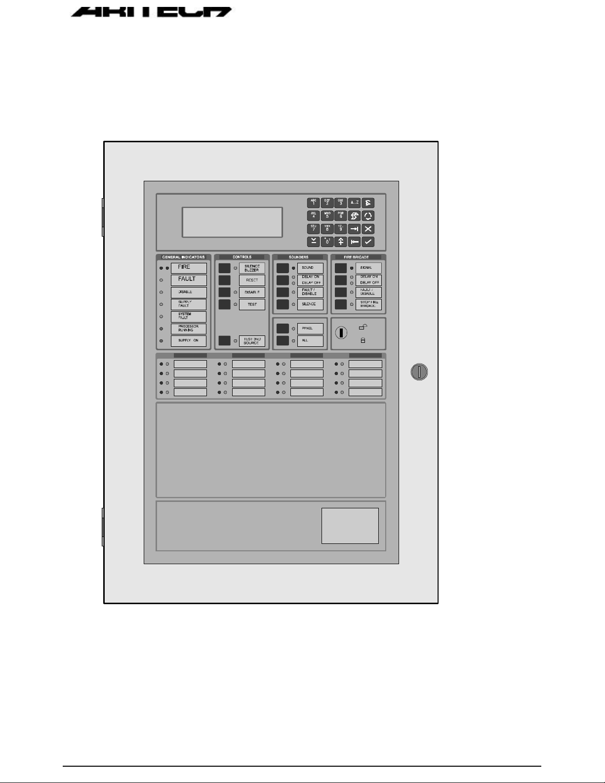
2. PANEL OPERATION
A view of the front of a typical FP2000 Series Fire panel is shown in Figure 1 below.
Figure 1: Fire Panel Front View
Page 7
In order to describe the operation of a FP2000 series fire panel, the front panel has
been divided into two sections, these being:
• LED indicators and controls
• LCD and keypad
2.1
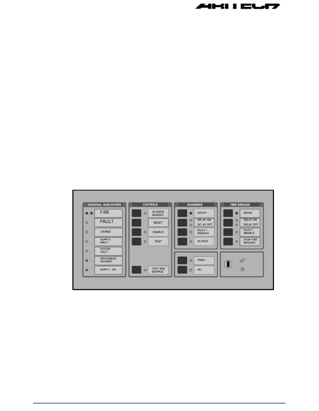
LED INDICATIONS AND CONTROLS
The LED indications and controls can further be broken down into:
• General indicators
• Controls
• Sounders
• Fire Brigade
• Enable/Disable keyswitch
• Zone indicators
Figure 2: General Indications and Controls
Page 8

2.2 GENERAL INDICATORS
COMMON FIRE
Two red LED's indicate that a fire has been detected.
COMMON FAULT
A common fault may be caused by one or more of the following:
• Device fault
• Zone fault
• Supply fault
• Processor fault
• Bell fault
• Fire Brigade fault
• Any test mode
• Any disable mode
COMMON DISABLE
A yellow LED indicates that one or more of the following have been disabled:
• Devices on the loop
• Zone
• Sounders
• Fire Brigade
• Any delays ON
SUPPLY FAULT
A yellow LED will illuminate for:
• Mains failure
• Battery disconnect or not charging
Page 9

SYSTEM FAULT
A yellow LED indicates that a system fault has occurred. A system failure can be one
or more of:
• Internal memory failure
• Clock failure
• Watchdog time out
• Tamper switch
• Service switch
• Logic error
• Memory lock
• No checksums calculated
• Hardware test fault
• Fireman’s' panel down
• Repeater down
• Panel down
• Global repeater down
• Input fault
• Output fault
• Configuration fault
• Checksum fault
• Protected memory overwritten
• Time date wrong
• Access fault
• FEP fault
• Watchdog time-out
PROCESSOR RUNNING
A flashing green LED indicates normal operation.
SUPPLY ON
A green LED indicates that the system is receiving 24V power.
Page 10

2.3 CONTROLS
SILENCE BUZZER (Keyswitch or )
The internal panel buzzer is activated for any new condition. The buzzer will be
continuous for a fire alarm condition, intermittent for a fault warning and slow
intermittent for a condition warning.
The buzzer is silenced by pressing the Silence Buzzer Key. The yellow silence
buzzer LED will illuminate to indicate that the buzzer has been silenced.
RESET (Keyswitch
)
This push-button will reset the fire panel.
DISABLE (Keyswitch
)
This push-button calls up the Disable Menu. The Common Disable LED will indicate
if anything is disabled.
TEST (Keyswitch
)
This push-button calls up the Test Menu. The yellow LED will illuminate if the panel
is put into a test mode.
Page 11

2.4 SOUNDERS
SOUND
A red LED indicates that the sounders have been activated.
Depends on the operation mode of the panel. Please refer to your Installer to the
exact way of operation.
DELAY ON/OFF
The programmed Sounder Delay may be toggled ON or OFF. Two LED’s indicate the
state.
FAULT/DISABLE (Keyswitch
)
The Sounder Fault/Disable push-button allows the sounders to be disabled. The
associated LED indicates that the sounders have been disabled or that a sounder
fault is present.
The sounder fault can be:
• Sounder circuit open circuit
• Sounder circuit short circuit
• Sounder circuit fuse failure
SILENCE (Keyswitch
)
A yellow LED indicates that the sounders have been silenced.
Please refer to your Installer to the exact way of operation.
Page 12

2.5 FIRE BRIGADE
SIGNAL (Keyswitch )
A red LED will indicate that the signal has been activated.
Please refer to your Installer to the exact way of operation.
DELAY ON/OFF
The programmed Fire Brigade Signal Delay may be toggled ON or OFF. Two LED’s
indicate the state.
FAULT/DISABLE (Keyswitch )
The Fire Brigade output may be disabled by using this push-button. When the signal
is disabled, then the disable LED will be illuminated.
The Fire Brigade circuit is monitored. The Fire Brigade fault LED will flash when a
fault is detected in the circuit.
STOP FIRE BRIGADE (Keyswitch
)
A yellow LED will indicate that the Fire Brigade signal has been deactivated.
Please refer to your Installer to the exact way of operation.
Page 13

KEYSWITCH: /
A keyswitch is provided to either allow or prevent operation of the fire panel controls.
The Silence Buzzer and Test keys will operate with the keyswitch in any position.
! Note: Level 1 for Disable and level 2 for Enable must not be confused with access
levels 1 and 2. There is no relation between the Enable/Disable keyswitch
and the allocated access levels.
2.6
OTHER
PANEL
Used by global and local repeaters for panel emulations. With a global repeater, the
Panel key is pressed, then the number of the panel to be emulated, and then the
Enter (
To stop emulation, the Panel key is pressed, then "0" and the Enter (
When a global repeater is emulating a panel it is not necessary to stop emulation
before emulating another panel. The global repeater will automatically stop the
emulation before trying to emulate another panel.
With a local repeater, pressing the Panel key will start emulation of the panel and if
the panel is already emulated, pressing the Panel key will stop emulation.
The yellow LED indicates whether a panel is emulated or not.
) key.
) key.
ALL
Used by the global repeater panel to send a command to all the panels that the
global repeater is communicating with. The yellow LED indicates that the key was
pressed, meaning that the following command button to be pressed will be sent to all
the relevant panels.
Page 14

THIRD SOURCE TEST (If Installed)
This key tests the third source battery when the panel is powered on. Pressing the
key will sound the buzzer.
2.7 ZONE INDICATORS
Each zone has two indicators. A red LED indicates a fire and a yellow LED indicates
a fault. The zone fault LED will flash for a fault condition. The zones are numbered
from the top left, from left to right.
2.8
Figure 3: Zone Fire and Fault Indication
LCD AND KEYPAD
Figure 4: LCD and Keypad
Page 15

KEYPAD
The keypad consists of 20 keys, 10 of which are alphanumeric keys.
The remaining 10 are assigned various functions as detailed below:
Alpha selection when using any of the 10 alphanumeric keys.
Used to display the latest alarm at any time.
Print screen function to print any screen to the internal or external printers.
Scroll key used to move between Alarm, Fault and Conditions, as well as to
view additional information when the "MORE" prompt appears on the LCD.
Exit to previous menu
Enter or confirm
Move to the next field in the display
Move to the previous field in the display
Increment
Decrement
Page 16

3. NORMAL OPERATION
Normal operation is indicated by:
3.1 SUPPLY ON - Green Lamp ON
3.2 PROCESSOR RUNNING - Green Lamp FLASHING
3.3 SOUNDER INDICATORS - DELAY ON or DELAY OFF - Yellow Lamp ON
If a delay is ON, the disable LED will go on; this will be logged as a condition. Press the
SILENCE BUZZER to silence the buzzer.
3.4 FIRE BRIGADE INDICATORS - DELAY ON or DELAY OFF - Yellow Lamp ON
If a delay is ON, the disable LED will go on; this will be logged as a condition. Press the
SILENCE BUZZER to silence the buzzer.
3.5 All other Lamps OFF
3.6 The screen shows the System Status Menu as shown below:
3.7 The panel buzzer will sound for any abnormal condition that occurs with the fire panel.
Page 17

4. IN CASE OF FIRE
4.1 The dual RED Lamps opposite FIRE will illuminate. The panel buzzer will sound and
any external bell or siren will be activated.
4.2 The location of the fire alarm(s) is displayed on the screen as shown below. If more
than one fire alarm exists then use the
4.3 Press (DISPLAY ALARM) to view the latest alarm.
4.4 Press SILENCE BUZZER to silence the panel buzzer and to acknowledge an alarm.
4.5 SOUNDERS
Once the evacuation of the building has been completed or a false alarm identified,
the sounders can be silenced as detailed below:
to view each alarm.
4.5.1 Turn the Keyswitch to
4.5.2 Press the SILENCE push-button. The yellow SILENCE lamp will illuminate.
4.5.3 To re-initiate evacuation press the SOUND push-button. The red SOUND lamp
will illuminate.
(Enable).
Page 18

4.6 RESTORE TO NORMAL
4.6.1 When the fire situation is under control, then the fire panel can be brought to a normal
condition by turning the keyswitch to
4.6.2 If a fire condition re-occurs, then one of the following exists:
• The fire is not under control - Refer to 4.2 above
• A Manual Call Point Glass is broken - Repair or isolate
• Detectors are contaminated with smoke - Clean detectors
4.6.3 Reset the fire panel as per 4.6.1.
and pressing the RESET push-button.
Page 19

5. IN CASE OF PRE-WARNING
5.1 The location of the detector in pre-warning is displayed on the LCD screen as shown
below. If more than one pre-warning condition exists, then use the to
view each pre-warning condition.
5.2 Press SILENCE BUZZER to silence the panel buzzer and acknowledge the pre-
warning.
5.3 Investigation should be carried out into the cause of the pre-warning condition.
5.4 RESTORE TO NORMAL
5.4.1 When the pre-warning condition is under control, then the fire panel can be brought to
a normal condition by turning the keyswitch to
button.
5.4.2 If a pre-warning condition re-occurs, then one of the following exists:
• The condition is not under control - Refer to 5.3 above
• Detectors are contaminated with smoke - Clean detectors
5.4.3 Reset the fire panel as per 4.6.
and pressing the RESET push-
Page 20

6. IN CASE OF FAULT
6.1 The yellow lamp opposite FAULT indicates that a fault has occurred in the fire
system.
6.2 Press the SILENCE BUZZER push button to silence the internal panel buzzer.
6.3 The nature of the fault is further displayed by a yellow lamp opposite:
6.3.1 A particular zone - Call maintenance engineer.
6.3.2 SUPPLY FAULT - Check mains supply and battery.
6.3.3 SYSTEM FAULT - Call maintenance engineer.
6.3.4 DISABLE - A zone, loop or device has been disabled.
6.3.5 TEST - A specific zone has been placed in test mode.
6.3.6 FAULT/DISABLE under SOUNDER - The warning bell or sirens have been
disabled or a fault is present on the connection.
6.3.7 FAULT/DISABLE under FIRE BRIGADE - The FIRE BRIGADE warning has
been disabled or a fault is present on the connection.
6.4 The exact nature and location of the fault is displayed on the LCD screen as shown
below:
Page 21

7. ROUTINE MAINTENANCE
In order to ensure the reliable operation of the FP2000 Series systems, they should be
regularly tested and serviced.
The following maintenance routine should be adopted:
7.1 DAILY
On a daily basis the user should check the following:
7.1.1 that the panel indicates normal operation, or if not, that any fault indicated is
recorded in the logbook and reported to the maintenance personnel;
7.1.2 any fault warning recorded the previous day has received attention;
7.1.3 that the printer ribbon and paper supply are adequate (if applicable), or else
replace as shown in Appendix A.
7.2 QUARTERLY
On a quarterly basis the following actions should take place:
7.2.1 logbook entries should be checked and the necessary action taken;
7.2.2 the state of the batteries and corresponding connections should be checked;
7.2.3 the fire panel should be visually inspected for signs of moisture ingress and
other deterioration;
7.2.4 the alarm, fault and ancillary functions of the fire panel should be tested.
Page 22

7.3 YEARLY
At least once every year the following should be checked:
7.3.1 the inspection and test routines recommended daily and quarterly should be
performed;
7.3.2 each detector should be checked for correct operation in accordance with the
manufacturer's recommendations;
7.3.3 a visual inspection of all cable fittings and equipment should be undertaken to
ensure that no damage has taken place;
7.3.4 a visual inspection should be made to ensure that no structural or occupancy
changes have affected the requirements for the siting of the manual call points,
detectors and sounders.
Page 23

FP2000 SERIES ANALOGUE ADDRESSABLE FIRE PANEL: USER INSTRUCTIONS Version 3.1
APPENDIX A
INSTALLING A NEW PRINTER CARTRIDGE
A ribbon cartridge has been loaded inside the printer before shipping. When the printing
becomes faint, load a new printer cartridge as follows:
1. Open the door of the fire panel and locate the printer (bottom left hand side internally
on the door).
2. Loosen the two retaining screens as shown in Figure A.1 below and gently remove
the printer.
Figure A.1: Printer Retaining Screws
Page 24

3. Remove the front cover of the printer. (Figure A.2)
Figure A.2: Removal of Printer Front Cover
4. Remove the old printer cartridge. (Figure A.3)
! Note: First lift the left end of the printer cartridge, then the right.
Figure A.3: Removal of Printer Cartridge
Page 25

FP2000 SERIES ANALOGUE ADDRESSABLE FIRE PANEL: USER INSTRUCTIONS Version 3.1
5. Replace with a new printer cartridge as follows:
Remove the paper roll. Put the right end of the cassette onto the axle on the printer
head, then the left end. If it is difficult to push the right end down, rotate the gear
slightly as indicated (see arrow on cassette cover). When the cassette clips into
place, check that the ribbon is straight. If not, rotate the gear.
6. Replace the front cover.
7. Remount the printer to the door ensuring the retaining screws are firmly tightened.
Page 26

Page 27

APPENDIX B
INSTALLING NEW PRINTER PAPER
The printer is shipped with a roll of paper loaded, but not fed to the printer head. This is to
prevent damage. Before use, feed the paper in as follows:
1. Open the door of the fire panel and locate the printer (bottom left hand side internally
on the door).
2. Loosen the two retaining screws as shown in Figure B.1 below and gently remove
the printer.
Figure B.1: Printer Retaining Screws
Page 28

3. Remove the front cover of the printer (Figure B.2).
Figure B.2: Removal of Printer Front Cover
4. If a paper roll has not been installed, remove the axle rod (Figure B.3), slide on the
paper roll and replace the loaded axle rod in the slots (Figure B.4).
Figure B.3: Removal of the Axle Rod
Page 29

Figure B.4: Replacing of Axle Rod and Paper Roll
5. Cut the paper as shown in Figure B.5.
Figure B.5: Cutting of Printer Paper
6. Remove the printer cartridge as shown in Appendix A. Turn the roller gear anticlockwise with your thumb until the paper begins to come out of the exit slot.
7. Replace the front cover.
8. Remount the printer to the door ensuring the retaining screws are firmly tightened.
 Loading...