

Page 1

FP2000 SERIES
NETWORK
CONFIGURATION GUIDE
Revision 1.1 : May 1997
Downloaded from: http://www.guardianalarms.net
Page 2

Page 3

CONTENTSCONTENTS
1. SCOPE 1
2. INTRODUCTION 2
2.1 GENERAL 2
2.2 NETWORK OVERVIEW 3
2.3 RS485 MEDIUM 4
2.3.1 General 4
2.3.2 Multi-drop Wiring 5
2.3.3 Bus Termination 5
2.3.4 Biasing 6
2.3.5 Cable Length / Type, Screening and Earthing 7
2.3.6 Line Extensions — Star Point Connections 7
2.4 RS232 MEDIUM 7
2.4.1 General 7
2.4.2 Restrictions 8
2.4.3 Connections 8
2.5 NETWORK INSTALLATION PARAMETERS 8
2.5.1 Node ID 8
2.5.2 Network Operation Mode 9
2.5.3 Port Allocation (not applicable for UN2000, NA/NH2000) 9
2.5.4 Data Rate For the RS485 medium 10
2.5.5 Baud Rate for the RS232 Medium 10
2.5.6 Node Relationship And Fault Reporting
(Not applicable for UN2000, NA/NH2000) 11
3. NETWORKING A 2000 SERIES FIRE PANEL 12
3.1 RS485 NETWORK INTERFACE (NC2000) 12
3.2 SOFTWARE CONFIGURATION 13
3.2.1 Node Identification (see also paragraph 2.5.1) 13
3.2.2 Port Set-Up 13
3.2.3 Network Communication 14
3.2.4 Example 14
3.3 NOTES 14
Page 4

4. NETWORKING LOCAL REPEATERS / GLOBAL REPEATERS 15
4.1 MODEL OVERVIEW 15
4.2 RS485 NETWORK INTERFACE 15
4.3 SOFTWARE SETTINGS TO BE PERFORMED 15
4.4 EMULATION — OPERATING GUIDELINES 15
4.4.1 Global Repeater 15
4.4.2 Local Repeater 16
5. UNIVERSAL NODE UN2000 17
5.1 GENERAL 17
5.2 HARDWARE OVERVIEW 18
5.2.1 PCB Layout and Rear Panel 18
5.2.2 Power Supply 19
5.2.3 Indicators 19
5.2.4 RS485 Bus Configuration Links (See also paragraph 2.3.3) 19
5.2.5 Node Identification Switches (See also paragraph 2.5.1) 20
5.2.6 General Option Switches 20
5.2.7 Reset Button 21
5.2.8 RS232 Interface 21
5.2.9 RS485 Interface 21
5.2.10 Note 21
5.2.11 Universal Node Specification 21
6. NETWORK AMPLIFIER AND HUBS 23
6.1 GENERAL 23
6.1.1 RS485 Extension 23
6.1.2 Star Point Connection 24
6.2 PRODUCT OVERVIEW 24
6.3 HARDWARE OVERVIEW 25
6.3.1 NA2000 Network Amplifier 25
6.3.2 NH2004/2008 Network Amplifiers 26
6.4 485 CHANNEL CONFIGURATION 27
6.4.1 General 27
6.4.2 Termination Resistor (See also paragraph 2.3.3) 28
Page 5

6.5 INSTALLATION 29
6.5.1 NA2000 Installation into a FP2864 Fire Panel 29
6.5.2 NA2000 Installation into a Panel without a Front End Processor 30
6.5.3 NH2004 / NH2008 Installation 30
6.6 NETWORK AMPLIFIER SPECIFICATION 31
7. INTERPANEL I/O PROGRAMMING 33
7.1 GENERAL 33
7.2 EXAMPLE 34
8. PRACTICAL EXAMPLE 36
Page 6

Page 7

1. SCOPE
This manual serves as a guide to the user when installing and configuring the FP2000
Network.
Other Manuals are:
Product Code
FP2000 Reference Guide LKFP2503
FP2000 Series Installation & Commissioning Manual LKFP2003
User Manual LKFP2403
2000 Series Sensors Installation Manual LKFP2203
Aritech 950 Series Devices Installation Manual LKFP2103
Page 8

2. INTRODUCTION
2.1 GENERAL
The FP2000 offers, as an option, unsurpassed networking capabilities with Arcnet using
RS485 for rugged, reliable and peerless operation. Products from the FP2000 series can
be added and removed from the network which allows for easy expansion of the system.
• RS485 nodes are available from the network for connection to Building Management
Systems
• Remote Maintenance
• PC Based Graphic Packages
• Interpanel I/O Programming
• Remote upload/download capability
• In addition, serial ports can be configured to allow for direct access to the network.
• The following table lists the devices that can be put on the network:
FP2000 Series Fire Panels
FR2000 Series Repeaters
RP2000 LCD Repeater
UN2000 Universal Node
NA2000/NH2000 Series Network Amplifiers
Note: ARCNET is a registered trademark of Datapoint Corporation.
Page 9
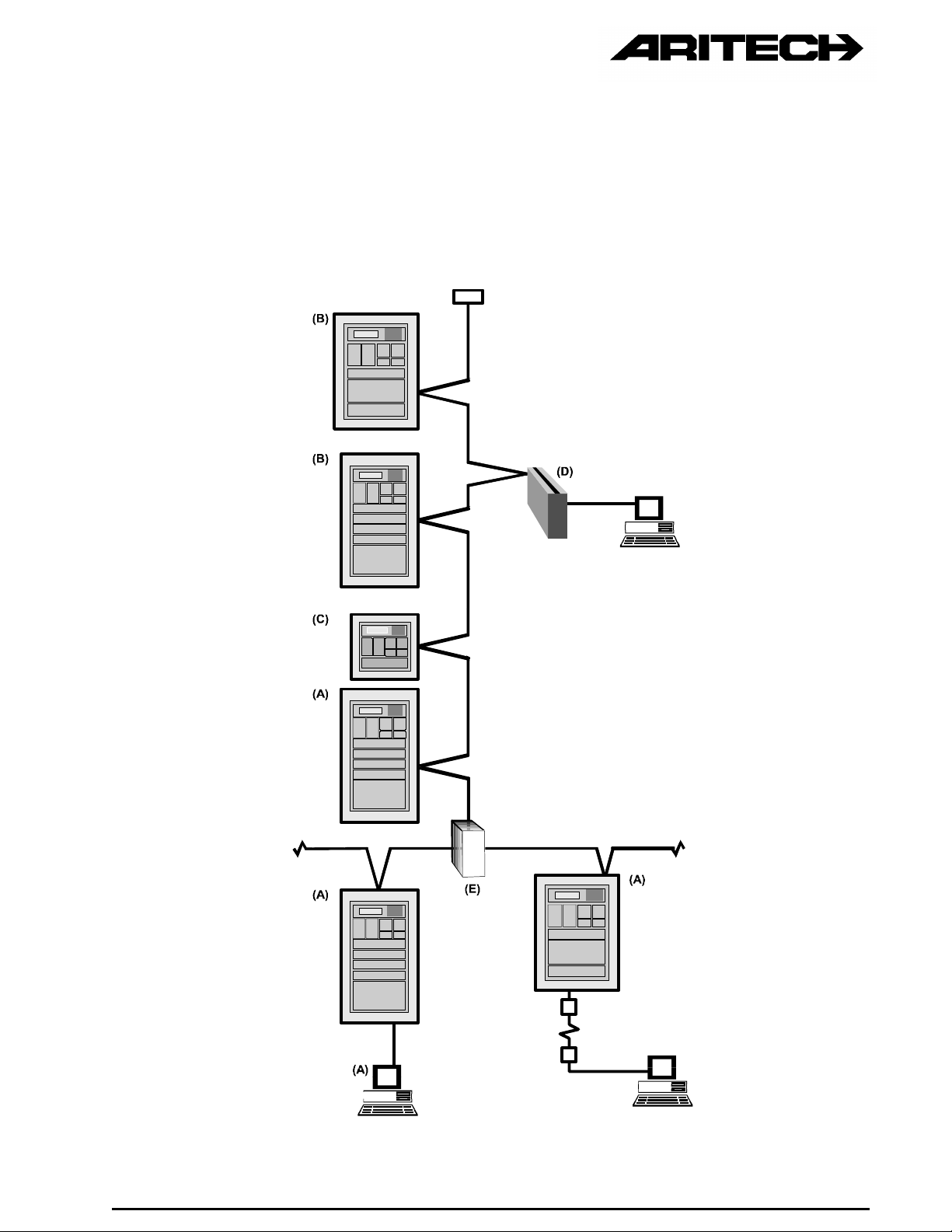
2.2 NETWORK OVERVIEW
The network may best be described by referring to Figure 1 which depicts a typical
network with its components.
Figure 1 : A Typical Network
Page 10

The following components/products are fully compatible with the network and can be
included when designing and configuring a system:
ANY FP2000 SERIES ANALOGUE ADDRESSABLE FIRE PANEL (A)
(Refer to paragraph 3).
ANY FR2000 SERIES REPEATER PANEL/EMULATOR (Global and Local) (B)
(Refer to paragraph 4).
The Repeaters/Emulators display on their front panel the status of the fire panel(s). It also
allows all fire panel operations to be performed from the Repeater.
ANY RP2000 SERIES LCD REPEATER PANEL (C)
The Repeater Panels displays the status of the fire panel(s). It also enables some
operations to be performed on the fire panel(s).
(Refer to paragraph 4).
UNIVERSAL NODE UN2000 (D)
The Universal Node provides an access point for external systems (such as computers) to
the FP2000 Arcnet network. It also enables some operations to be performed on the Fire
Panel(s).
(Refer to paragraph 5).
NETWORK AMPLIFIER (NA2004/NH2004/NH2008) (E)
The Network amplifier makes RS485 line extension and star point connections to the
network possible.
(Refer to paragraph 6).
2.3 RS485 MEDIUM
2.3.1 General
A network can be established using fully isolated RS485 drivers as the electrical
medium for communication. The RS485 concept is a two wire "multi drop" system
that allows for bi-directional communication at high speed in noisy industrial type
environments. While providing one of the easiest forms of network interconnection,
the RS485 standard does require certain precautions when putting together a
system.
The Arcnet protocol used is a token-passing protocol and is well proven and
reliable. It is ideally suited for critical applications as each network event occurs
within a predictable and predetermined response time.
Page 11
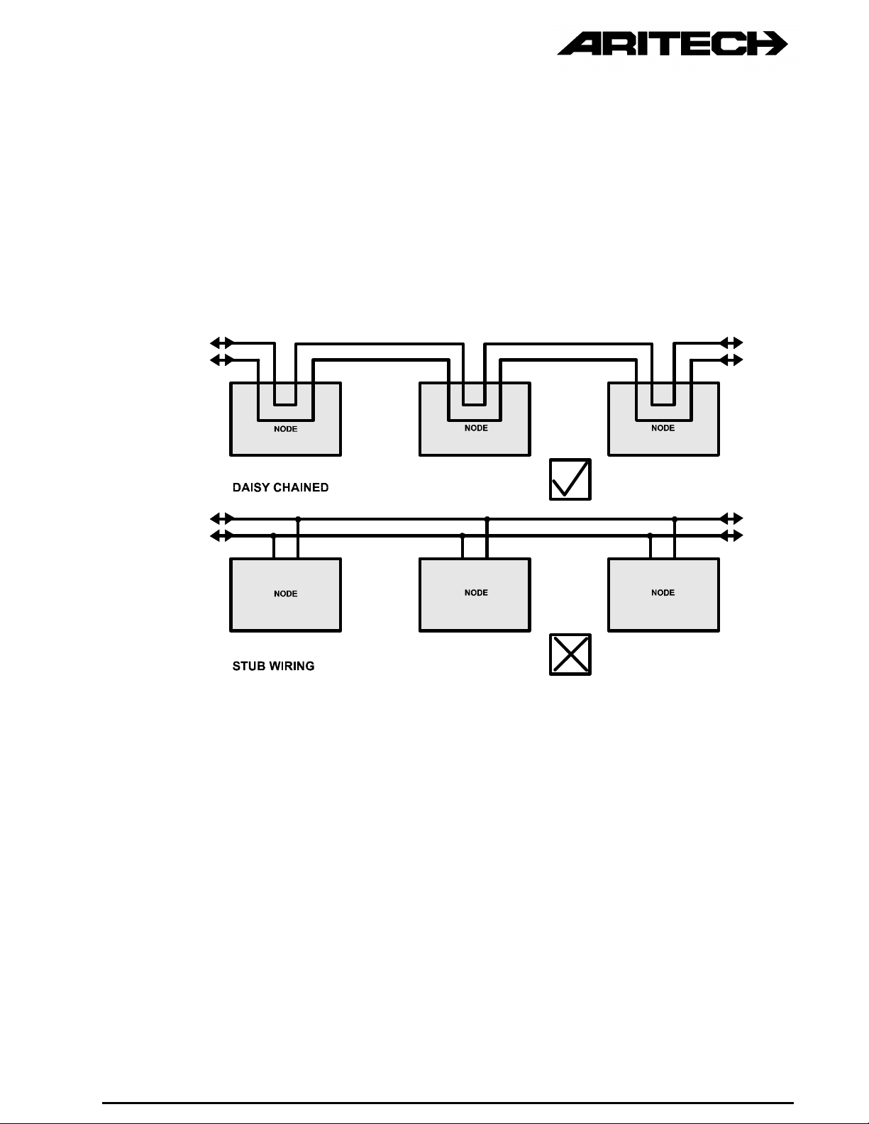
2.3.2 Multi-drop Wiring
Multi-drop wiring implies a two wire bus connected to each network node. The
recommended method is to wire the nodes in a daisy chain, where the bus enters
and leaves each node. Four terminals are usually provided (there are exceptions)
on each network component. The use of stub wiring is not recommended. Refer to
Figure 2 below for the difference between stub and daisy-chain wiring methods.
Figure 2 : Daisy-Chained and Stub Wiring
2.3.3 Bus Termination
The network two-wire bus must be terminated at each end with a resistor. The spare
terminals of the nodes at each end can be used. The value of the termination
resistor must be equal to the characteristic impedance of the cable. Links are
provided on network equipment for terminating into 120 ohm resistors. Resistors
can be added in parallel (with the links not in place) if the characteristic impedance
of the cable used is not 120 ohm. The characteristic impedance of cable can vary
quite substantially and must be taken into consideration when selecting cable for
network applications.
Beldin 9841 cable (recommended) R = 120 Ohm
Telephone cable R = 100 Ohm
Page 12
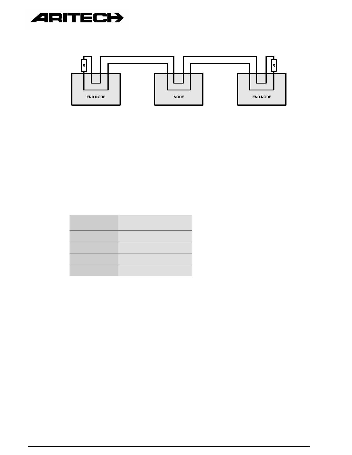
Figure 3 : Bus Termination
2.3.4 Biasing
There are four sets of bias resistor links, each set consisting of two links are
provided for each of the network nodes. One link is for the RS485 positive (+) line
and the other for the negative (-) line. These links must be set on all nodes
connected to the network. The number of nodes determines the setting of the bias
resistor links and needs to be changed if nodes are added or removed from the
network. No change of biasing is required if changes to the number of nodes are
made within the groups indicated below.
Group Number of Nodes
1 1 to 6
2 7 to 14
3 15 to 22
4 23 to 32
For details on setting the biasing resistor links refer to the relevant equipment
documentation in the next paragraphs.
Page 13

2.3.5 Cable Length / Type, Screening and Earthing
The maximum cable length is determined by three factors:
1. The data rate of the network
2. The capacitance/Km of the cable (both core to core and core to shield)
3. The loop resistance (core size ) of the cable
The maximum recommended length using Beldin 9841 cable or equivalent is 1500m
(1.5 km).
Twisted pair unshielded cable can be used in low noise environments, but is not
recommended.
Specification: Single twisted pair with screen and earth drain
Capacitance : 41.7 pF/m core to core
: 75 pF/m each core to screen
Characteristic Impedance : 120 Ohm
Screens of the RS485 line must be earthed at one point only. Terminals are
provided on network components to terminate and to continue the screen of the
cable.
2.3.6 Line Extensions — Star Point Connections
The Network Amplifier provides the user the ability to:
• Extend the length of the ARCNET RS485 line of the FP2000 range of fire
panels.
• Make star point connections to the ARCNET RS485 thereby increasing the
flexibility of the network cabling.
(Please refer to paragraph 6).
2.4 RS232 MEDIUM
2.4.1 General
A network can also be set up via the RS232 ports provided on the FP2000 range of
fire panels.
Typical applications are:
• Remote alarm reporting (via modem)
• Graphic package with only one fire panel
• Remote maintenance (via modem)
• Configuration of panel (using “remote maintenance manager” software)
Page 14

2.4.2 Restrictions
• The maximum distance is limited (typically 10m). Distance can eventually be
increased by means of line drivers.
• The connection is always point-to-point.
Networking via RS232 between two 2000 series devices (universal node, repeaters,
panels) is not recommended; the “other” side should always be a PC or modem.
2.4.3 Connections
• When a PC is connected, a crossed cable (“null-modem”) has to be used.
• When a modem is connected, a “straight” cable can be used.
For cable configurations, please refer to Appendix A.
2.5 NETWORK INSTALLATION PARAMETERS
2.5.1 Node ID
All 2000 network devices must have a unique non-zero node identification address
(ID) to be able to communicate with other 2000 devices.
The node ID has the following structure: P/R. (Panel number / Repeater number)
There are three different kinds of node ID’s:
1. Panel:
Node ID on which detectors are connected
FP2416, FP2864, FP2432
Structure: P/0 (second part is always 0)
2. Global Repeater:
The node will be able to repeat and in some cases emulate all other programmed
panels on the network.
Structure: O/R (First part always 0)
3. Local Repeater:
The node will repeat and in some cases emulate only one panel on the network.
Structure: P/R
P : Panel ID it has to repeat
R : Number of Repeater from Panel P.
Examples:
• Fire Panel 3 : 3/0
• Global Repeater 4 : 0/4
• Local Repeater 7 of Fire Panel 3 : 3/7
Page 15

2.5.2 Network Operation Mode
The maximum number of panels, local and global repeaters that can be put on the
network depends on the operation mode.
There are three (3) modes namely:
15/15 (Default Setting)
Max. 15 Panels
Max. 15 Global Repeater Panels
Max. 15 Local Repeater Panels per panel
7/31
Max. 7 Panels
Max. 31 Global Repeater Panels
Max. 31 Local Repeater Panels per panel
31/7
Max. 31 Panels
Max. 7 Global Repeater Panels
Max. 7 Local Repeater Panels per panel
The amount of nodes can never exceed 255 irrespective of the mode selected
(excluding electrical restrictions of the RS485 line) (see paragraph 2.3).
2.5.3 Port Allocation (not applicable for UN2000, NA/NH2000)
The following ports can be available for network purposes:
SER1 : RS232 serial ports
SER2 :
ARC1 : RS485 ports
ARC2 :
The ARC1/2 or SER1/2 ports on the devices are to be allocated to the Network
Communication Functions NET1/2.
None (default) - No network communications
NET1 (normally used) - All network communications set-up to NET1 will
communicate via the selected port.
NET2 - All network communications set-up to NET2 will
communicate via the selected port.
Page 16

Note1:
Not all of these ports are always available on a device; please refer to the
appropriate paragraph.
Note2:
Only one port can be allocated to NET1, only one port can be allocated to NET2.
2.5.4 Data Rate For the RS485 medium
The data rate should be the same for all Panels on the network.
The options are:
78 Kbps
156 Kbps (default)
312 Kbps
625 Kbps
1250 Kbps
Note: The UN2000, NA/NH2000 has a fixed data rate: 156 Kbps
2.5.5 Baud Rate for the RS232 Medium
The baud rate should be the same for the two devices that are communicating.
The options are:
300 baud
600 baud
1200 baud
2400 baud
4800 baud
9600 baud
19200 baud
38400 baud
Note: The UN2000 has a fixed data rate on the RS232 side: 9600 baud
Page 17

2.5.6 Node Relationship And Fault Reporting (Not applicable for UN2000,
NA/NH2000)
A FP2000 Fire Panel can be configured to communicate with any number of other
FP2000 Fire Panels, Global Repeaters and Local Repeaters as allowed by the
network configuration.
A Global Repeater can be configured to communicate with any number of FP2000
Fire Panels and other Global Repeaters as allowed by the network configuration.
The Global Repeater will not, however, communicate with Local Repeaters.
A Local Repeater can be configured to communicate with only one FP2000 Fire
Panel and not with Global Repeaters or other Local Repeaters.
For a specific panel to communicate with other panels, the status for each panel
number must be set to one of the following (default is None):
NET1 check - communicate on NET1, fault warning enabled
NET1 no check - communicate on NET1, fault warning disabled
NET2 check - communicate on NET2, fault warning enabled
NET2 no check - communicate on NET2, fault warning disabled
“fault warning enabled” means that when communication fails with that specific
node, a fault will be reported.
Page 18

3. NETWORKING A 2000 SERIES FIRE PANEL
3.1 RS485 NETWORK INTERFACE (NC2000)
Figure 4 : Network Interface and Associated Connection
RS485 BUS CONFIGURATION LINKS
Termination Resistor Link - J1 (see also paragraph 2.3.3)
The following two possibilities exist:
• If the NC2000 is at the end of the RS485 bus: Install link J1.
• If the NC2000 is not at the end of the RS485 bus: Remove link J1.
Bias Resistor Links - J2-5; J6-9 (see also paragraph 2.3.4)
There are four sets of bias resistor links, each set consisting of two links; one link for the
RS485 positive (+) line and the other for the negative (-) line.
The four sets are for different ranges of the amount of nodes on a RS485 bus.
The four sets of bias resistor links are divided as follows:
- Link + Link Range of Nodes
J9 J5 1 - 6
J8 J2 7 - 14
J7 J4 15 - 22
J6 J3 23 - 32
Both bias resistor links of a set must be in when the amount of nodes on the RS485 bus
are within that range, and out when it's not within the range.
Page 19

RS485 Screen Links - J10, J11 (see paragraph 2.3.5)
J10 should always be out.
When J11 is in, the screen is connected to Earth (only on one node on the whole network).
3.2 SOFTWARE CONFIGURATION
Each fire panel, global repeater or local repeater on a network must be configured
as follows:
3.2.1 Node Identification (see also paragraph 2.5.1)
The maximum configuration and Node ID of each panel should be set up under the
menu.
SYSTEM / CONFIGURATION / ID
The Node ID consists of two digits: panel number / repeater number (p/r)
The field “Panel” confirms the fire panel number. This is also shown on line 8 of the
display: P:p. For global repeaters the word “Panel” becomes “G-Repeater” and line
8 displays G:r. For local repeaters the display is “L-Repeater” and line 8 displays
L:p/r.
The Max. Config. Field shows the maximum number of panels and repeaters (global
or local) that can be configured. (See also paragraph 2.5.2).
3.2.2 Port Set-Up
When the RS485 medium is used, the ARC1 port should be allocated to NET1 or
NET2 (default is None), under the menu System / Configuration / Communication
/ Port Set-up.
The options are:
None (default) - No network communication
NET1 (normally used) - All network communications set-up to NET1 will talk via
NET2 - All network communications set-up to NET2 will talk via
The baud rate should be the same for all panels.
After the port set-up is completed, the red LED on the NC2000 should come on
steady (if there is more than one node enabled on the network).
When the RS232 medium is used, NET1 or NET2 should be allocated to the SER1
or SER2 port.
the ARCNET card
the ARCNET card
Page 20

3.2.3 Network Communication
The communication between nodes on the network should be enabled under the
menu System / Configuration / Communication / Network. In each node, enable
the node with which this node has to communicate (NET1 or NET2) and define fault
warnings (check - no check).
3.2.4 Example
ID 1/0 0/1 2/0
Port ARC1=net1 ARC1=net1 ARC1=net1
Network P2:net1 no check* P1:net1 check P1:net1 no check
G1:net1 check** P2:net1 check G1:net1 check
* Panel 1 will not give a fault when comm. fails with panel 2 (the same has been
programmed on panel 2).
** Panel 1 will give a fault when comm. fails with Global Repeater (0/1) (the same has been
programmed on panel 2).
3.3 NOTES
The FP2000 series fire panels are delivered without a network card. The NC2000
must be ordered as a separate product.
Page 21

4. NETWORKING LOCAL REPEATERS / GLOBAL REPEATERS
4.1 MODEL OVERVIEW
Three repeater models are available:
1. FR2032
Zone LED’s (max. 32) / 24V DC / small housing / no internal printer optional
2. FR2064
Zone LED’s (max. 64) / 24V DC / large housing / internal printer optional
3. RP2000
No zone LED’s / 24V DC / mini housing / no internal printer optional / no
emulation possible
All models have the Arcnet based NC2000 on board.
All of these models can be configured as a local or global repeater. When
configured as a local repeater, the LED’s (if present) will repeat the zones of the
panel; when configured as a global repeater, the LED’s will act as “Panel LED’s”,
i.e. Every panel on the network will have its own fire and fault LED.
4.2 RS485 NETWORK INTERFACE
(Please refer to paragraph 3.1).
4.3 SOFTWARE SETTINGS TO BE PERFORMED
(Please refer to paragraph 3.2).
4.4 EMULATION — OPERATING GUIDELINES
4.4.1 Global Repeater
Any fire, fault or conditions present on any fire panel on the network that is
configured to communicate with the Global repeater will be indicated by the LED's
and/or displayed by the LCD on the Global repeater. When stepping through the
events on the Global Repeater the events of any Fire Panel or Global Repeater will
be displayed in historical order.
Page 22

Any fire panel on the network that is configured to communicate with the Global
repeater can be emulated from the Global Repeater. This is done from the Panel
key on the front of the Repeater. Press the Panel key followed by the number of the
Panel to be emulated. While emulating a Fire Panel, the ID of that Panel will be
displayed on the Global Repeater (bottom right corner). Any keys pressed during
emulation are treated by the emulated Panel as if pressed on its own front panel. To
exit from emulation, enter Panel 0 after pressing the Panel key. If a time-out (no key
pressed for 10 minutes) occurs or if the communication to the Panel goes down, the
Global Repeater will terminate the emulation mode.
All the Fire Panels on the network can be controlled simultaneously from the Global
Repeater. This is done by using the ALL key on the front of the Repeater. Use this
key followed by the control key required.
If the network should go down, the Global Repeater will indicate Panel faults and
the Fire Panels will each indicate a Global Repeater fault (if fault warning is
enabled). Once the network is restored, all the fault indications will disappear.
4.4.2 Local Repeater
Any fires, faults or conditions present on the fire panel that is configured to
communicate with the Local Repeater will be indicated on the Local Repeater. All
control keys on the Local Repeater are treated as if pressed on the Fire Panel.
The fire panel can be emulated from the Local Repeater. By pressing the panel key,
the Local Repeater will start emulating the fire panel and the ID of the Fire Panel will
be displayed on the Local Repeater (bottom right corner). Any keys pressed during
emulation are treated by the emulated Panel as if pressed on its own front Panel
(including the control keys). To exit from emulation press the Panel key again. If a
time-out (no key pressed for 10 minutes) occurs or if the communication to the
Panel goes down, the Local Repeater will terminate the emulation mode.
If the network should go down, the Local Repeater will indicate a panel fault and the
fire panel will indicate a Local Repeater fault (if fault warning is enabled). Once the
network is restored, all the fault indications will automatically disappear.
Page 23

5. UNIVERSAL NODE UN2000
5.1 GENERAL
The Universal Node provides an access point for external systems to the FP2000
ARCNET network.
The basic function of the Universal Node may best be described by referring to
Figure 5, which depicts the unit in a typical application.
Figure 5 : Universal Node Depicted In Actual Application
The Universal Node is powered from mains. It interfaces to the RS485 network via
two wires and is connected to external systems by means of a RS232 cable.
Functionally it forms the interface (translator) extension for the external system and
is therefore only operational while the RS232 system is in operation. It cannot
operate as a stand-alone unit.
The RS232 configuration of the Universal Node is fixed while its RS485
configuration must be tailored to suit the network that it is connected to.
To change the configuration the Universal Node box must be opened to have
access to the printed circuit board.
Page 24

5.2 HARDWARE OVERVIEW
5.2.1 PCB Layout and Rear Panel
The rear panel and circuit board (top view) of the Universal Node is shown in Figure
6 below:
ARCNET
Figure 6 : UN2000 PCB Layout and Rear Side
Page 25

5.2.2 Power Supply
The Universal Node is powered from 230V 50 Hz AC. A Power On/Off switch with
an indicator lamp is also provided. The power supply is protected by an onboard
fuse. (100 mA).
5.2.3 Indicators
Refer to Figure 6
5.2.4 RS485 Bus Configuration Links (See also paragraph 2.3.3)
Termination Resistor Link - J7 (see also paragraph 2.3.3)
The following two possibilities exist:
• If the Universal Node is at the end of the RS485 bus: Install link J7.
• If the Universal Node is not at the end of the RS485 bus: Remove link J7.
Bias Resistor Links - J3-6; J9-12 (see also paragraph 2.3.4)
There are four sets of bias resistors links, each set consisting of two links; one link
for the RS485 positive (+) line and the other for the negative (-) line.
The four sets are for different ranges of the amount of nodes on a RS485 bus.
The four sets of bias resistor links are divided as follows:
+ Link - Link
J6J12 1 - 6
J5J11 7 - 14
J4J10 15 - 22
J3J9 23 - 32
Both bias resistor links of a set must be in when the amount of nodes on the RS485
bus are within that range, and out when it's not within the range.
Earth Connection - J13 (see also paragraph 2.3.5).
If J13 is in, it connects the screen of the RS485 cable to earth. The screen must be
earthed at one node only. Note that J8 must always be out.
Range of Nodes
Page 26

5.2.5 Node Identification Switches (See also paragraph 2.5.1)
The Universal Node is normally used as a Global Repeater; therefore the node
identification will be 0/Repeater Number.
The node identification is transferred to the switches as follows:
node ID 8 7 6 5 4 3 2 1
0/1 ON ON ON ON ON ON ON OFF
0/2 ON ON ON ON ON ON OFF ON
0/3 ON ON ON ON ON ON OFF OFF
0/4 ON ON ON ON ON OFF ON ON
0/5 ON ON ON ON ON OFF ON OFF
0/6 ON ON ON ON ON OFF OFF ON
0/7 ON ON ON ON ON OFF OFF OFF
0/8 ON ON ON ON OFF ON ON ON
0/9 ON ON ON ON OFF ON ON OFF
0/10 ON ON ON ON OFF ON OFF ON
0/11 ON ON ON ON OFF ON OFF OFF
0/12 ON ON ON ON OFF OFF ON ON
0/13 ON ON ON ON OFF OFF ON OFF
0/14 ON ON ON ON OFF OFF OFF ON
0/15 ON ON ON ON OFF OFF OFF OFF
MM
5.2.6 General Option Switches
Switches 5 and 6 determine the ARCNET network mode and must be configured to
be the same as that of the network to which the Universal Node is attached.
The meaning is as follows:
Switch 5 Switch 6 Network Mode
ON ON 15/15
OFF ON 7/31
ON OFF 31/7
OFF OFF 15/15
Page 27

For normal use, the positions should be as follows:
OPTIONS 1 2 3 4 5 6 7 8
POSITION ON OFF ON ON X X ON ON
5.2.7 Reset Button
By pressing this button the UN is being reset.
5.2.8 RS232 Interface
A 9-pin D-type male connector is provided. The cable must be a 9 to 9 pin, or 9 to
25-pin crossover cable. Please refer to Appendix A.
5.2.9 RS485 Interface
The connections are as shown in Figure 6. Bit rate is fixed at 156 Kbps. The
FP2000 Serial Communication Format Guide is available on special request.
5.2.10 Note
The jumpers J1 and J2 must always be in the “B”-position.
5.2.11 Universal Node Specification
PERFORMANCE
Data Communication
RS232 Protocol : Eight Data Bits
RS485 Protocol : 156 Kbps (fixed)
Channels : 1x RS232
Power Supply
Input Power : 230 V AC ,50 Hz, 5 VA
Fuse Type : 500 mA 250V
One stop Bit
No Parity
Bits per second
DTE equipment
1x RS485
Physical Characteristics
Mass : 1.5 kg
Dimensions : 290 x 145 x 80 mm
Page 28

Environmental
Temperature
Operational : 0°C to 40°C
Storage : -30°C to 65°C
Relative Humidity : 20 to 80% (non-condensing)
Page 29

6. NETWORK AMPLIFIER AND HUBS
(NA2004 / NH2004 / NH2008)
6.1 GENERAL
The Network Amplifier provides the user the ability to:
• Extend the length of the ARCNET RS485 line of the FP2000 range of fire panels.
• Make star point connections to the ARCNET RS485 thereby increasing the
6.1.1 RS485 Extension
flexibility of the network cabling.
When FP2000 Panels are distributed over a large area the RS485 signal may get
attenuated to such an extend that it leads to unreliable communication. A Network
amplifier overcomes this problem as it re-transmits the signal it receives whereas on
a FP2000 Panel Arcnet Interface Printed Circuit Board the signal is only linked
through to the next device (refer to Figure 7).
Figure 7 : Network Extension
Page 30

6.1.2 Star Point Connection
Network Amplifier re-transmits an incoming signal on any one channel to all the
other available channels. This feature makes star point connection possible. More
channels can be added by plugging Network Amplifiers into each other (refer to
Figure 8).
Figure 8 : Star Point Connection
6.2 PRODUCT OVERVIEW
The following three (3) Network Amplifiers are available:
NA2000 NETWORK AMPLIFIER
The NA2000 Network Amplifier is a single Printed Circuit Board intended for use
inside the FP2000 series of panels as it makes use of the internal power supply of
the panel. Four RS485 channels are provided to enable network extension and star
point connections.
NH2004 NETWORK AMPLIFIER
The NH2004 Network Amplifier is intended for external use. It consists of the basic
NA2000 Network Amplifier card and a power supply mounted in a metal housing.
Provision is also made for housing and charging standby batteries from mains to
ensure full functionality upon interruption of power. Four RS485 channels are
provided to enable network extension and star point connections.
Page 31

NH2008 NETWORK AMPLIFIER
The NH2008 Network amplifier is identical to the NH2004 except that it makes use
of two basic NA2000 Network Amplifier cards to provide up to eight RS485
connections.
6.3 HARDWARE OVERVIEW
6.3.1 NA2000 Network Amplifier
The NA2000 Network Amplifier unit (printed circuit board) contains the following:
ISOLATED POWER SUPPLY
• Input: 10 - 28 volt DC
• Output: 5 volt
FOUR RS485 CHANNELS, EACH CONSISTING OF THE FOLLOWING
1 x RS485 driver
4 x Bias resistor links for the RS485 positive (+) line
4 x Bias resistor links for the RS485 negative (-) line
1 x Termination resistor link: J14/J23/J32/J41
1 x Terminal block connector with two (2) contacts: P6/P7/P8/P9
1 x Receive LED - red : LED1/LED2/LED3/LED4
1 x Transmit LED - green : LED5/LED6/LED7/LED8
Edge connectors for signal lines: P1, P2.
Edge connectors for power supply input source: P3, P4.
Molex connector for power supply input source: P5.
Link for connecting the 5V (Vcc) supply of Network Amplifier units together:J1
Link for selecting between power supply input sources: J2.
The card Amplifier is designed for ARCNET protocol data (baud) rates of 156.25
Kbps only.
Page 32

Figure 9 : NA2000 Network Amplifier — Connector, Link And LED Placing
6.3.2 NH2004/2008 Network Amplifiers
The NH2004 and NH2008 are stand alone units. Both make use of the NA2000
card and are provided with a mains power supply as depicted Figure 10 below. The
power supply contains screw terminals for connections to the mains supply, the
battery, and remote fault indication equipment. The fault indicator output consists of
normally open and normally closed relay contacts (2 Amp rated). In the normal
condition the Fault LED on the power supply board will be ON. The Fault LED and
relay contacts indicate mains power supply or battery fault conditions. The Supply
LED on the board indicates the presence of mains power when ON. The output of
the power supply (24 volt), is transferred to the NA2000 card via connector TB2.
Figure 10 : NH2004
Page 33

6.4 485 CHANNEL CONFIGURATION
6.4.1 General
The following table describes the relation between the channels, connectors, links
and LED's (see also Figure 9 in 6.3.1). Note that the channels are numbered only
for distinguishing between them.
Links LED
Channel Termination Biasing Terminal Block
1 J14 Nodes: "-" "+" P6 LED1 LED5
1 - 6 : J6 J10
7 - 14 : J7 J11
15 - 22 : J8 J12
23 - 32 : J9 J13
2 J23 Nodes: "-" "+" P7 LED2 LED6
1 - 6 : J15 J19
7 - 14 : J16 J20
15 - 22 : J17 J21
23 - 32 : J18 J22
3 J32 Nodes: "-" "+" P8 LED3 LED7
1 - 6 : J24 J28
7 - 14 : J25 J29
15 - 22 : J26 J30
RX
(green)
TX
(red)
23 - 32 : J27 J31
4 J41 Nodes: "-" "+" P9 LED4 LED8
1 - 6 : J33 J37
7 - 14 : J34 J38
15 - 22 : J35 J39
23 - 32 : J36 J40
Figure 11 : Network Amplifier Configuration
Note: All the screens of the different RS485 network cables must be tied together.
Page 34

6.4.2 Termination Resistor (See also paragraph 2.3.3)
Refer to Figure 11
If the Network Amplifier RS485 channel is at the end of a RS485 line:
• Termination resistor link of that channel must be in.
If the Network Amplifier RS485 channel is not at the end of a RS485 line:
• Termination resistor link of that channel must be open.
Unlike the RS485 network interface (NC2000), the Network Amplifier does not
provide two sets of RS485 signal terminal block contacts for one channel.
Therefore, when the network amplifier is not at the end of the channel, the two
positive (+) lines terminate into the same positive (+) terminal block contact and the
two negative (-) lines onto the same negative (-) terminal block contact.
Page 35

6.5 INSTALLATION
6.5.1 NA2000 Installation into a FP2864 Fire Panel
(i.e. a panel with front end processor)
• The following procedures are to be followed when installing a Network amplifier:
• Switch mains power to the FP2000 panel OFF
• Select either the lower or higher slot inside the lid of the front panel to mount the
Network amplifier
• The Network Amplifier is only compatible with the following printed circuit cards:
• FP2000 RS485 Network Interface (NC2000) CE-FP-334-X
• Host PSU Board CE-FP-327-X
• FP2000 Zone Board CE-FP-322-X
• Plug the Network Amplifier in and secure in position using the hardware
supplied.
• Ensure that link J1 is removed and that J2 is in position (refer to Figure 9).
• Identify the channels of the Network amplifier that will be connected to the end
of a RS485 line (not linked through). Install the relevant resistor termination links
for those channels (refer to Figure 11).
• Identify the channels of the Network Amplifier that will not be at the end of a
RS485 line (linked through). Remove the relevant resistor termination links for
those channels (refer to Figure 11).
• Identify the number of nodes per Network Amplifier channel. Insert biasing links
in accordance with the number of nodes as specified in Figure 11. Biasing links
of unused channels must also be installed (1 - 6 range).
• Connect the RS485 lines. Ensure that the polarity is correct. Only one set of
terminal blocks are provided per channel. If the channel is not at the end of a
line the two positive (+) lines will be terminated onto the same terminal block.
The same applies to the two negative lines (-). Connect the screens of all the
RS485 lines to each other.
• Note: If more than one Network Amplifier is used they must be plugged into
each other.
Do not install termination links for unused Network Amplifier channels (to conserve
power).
Note: Installing a NA2004 in a FP2416 is impossible.
Page 36

6.5.2 NA2000 Installation into a Panel without a Front End Processor
(FR2032 / FR2064)
The following procedures are to be followed when installing a Network amplifier:
• Switch the panel OFF
• Secure the Network Amplifier on the studs provided inside the rear panel using
the hardware supplied.
• Connect the Network Amplifier plug number P5 (refer to 10) to the Power Supply
(24 V DC) using the power cable supplied.
• Ensure that the link J1 and J2 is removed (refer to 10). Please note that the link
J2 must be removed from the first Network Amplifier only. Additional Amplifiers
plugged into the first unit must have the link J2 in position.
• Identify the channels of the Network amplifier that will be connected to the end
of a RS485 line (not linked through). Install the relevant resistor termination links
for those channels (refer to Figure 11).
• Identify the channels of the Network Amplifier that will not be at the end of a
RS485 line (linked through). Remove the relevant resistor termination links for
those channels (refer to Figure 11).
• Identify the number of nodes per Network Amplifier channel. Insert biasing links
in accordance with the number of nodes as specified in Figure 11. Biasing links
of unused channels must also be installed (1 - 6 range).
• Connect the RS485 lines. Ensure that the polarity is correct. Only one set of
terminal blocks are provided per channel. If the channel is not at the end of a
line the two positive (+) lines will be terminated onto the same terminal block.
The same applies to the two negative lines (-). Connect the screens of all the
RS485 lines to each other
Note: If more than one Network Amplifier is used they must be plugged into each
other. Do not install termination links for unused Network Amplifier channels
(to conserve power).
6.5.3 NH2004 / NH2008 Installation
• Mount the Unit in position using the mounting holes provided.
• Ensure that the link J1 is removed and that the link J2 is in position (refer Figure
10). Ensure that a proper ground connection is made to the housing.
• Connect the unit to mains power supply using the terminal block contacts in
accordance with the detail provided inside the unit.
• Install the relevant biasing and termination resistor link and connect the RS485
lines as described in Figure 11 above.
• Install the batteries. Ensure that the correct type of battery is used (refer to 6.6)
• Close the housing.
Page 37

6.6 NETWORK AMPLIFIER SPECIFICATION
DATA COMMUNICATION
Protocol : ARCNET
Data Rate : 156.25 Kbps
Channels : 4 (NA2000 and NH2004 version)
8 (NH2008 version)
Nodes : up to a maximum of 32 per channel
POWER SUPPLY
Input Power (NA2000) : 10 to 30 V DC, 1,8W
Input Power : NH2004, NH2008 230 V AC,
50 Hz, 10 VA
Fuse Type : NH2004, NH2008 500mA / 250 V
Charger : 13,8 V DC ±5%
Current limited 500mA Max.
Battery : Capacity 7,2 AH
Type: Sealed Lead Acid
PHYSICAL CHARACTERISTICS
Dimensions : NH2004,NH2008 331*254*81 mm
: NA2000 191*65 mm
Network Interface : Terminal blocks
ENVIRONMENTAL
Enclosure protection : NH2004, NH2008 IP3X3
(when using appropriate cable
glands on cable entries)
TEMPERATURE
Operational : 0°C to + 40°C
Storage : -30°C to 65°C (excluding batteries)
Page 38

Relative Humidity : 20 to 80% (non-condensing)
Page 39

7. INTERPANEL I/O PROGRAMMING
7.1 GENERAL
Through I/O programming, it is possible to transfer any input definition from a
network node to any output definition to another network node.
The communication between panels has to be enabled (with or without fault
reporting) under the menu System / Configuration / Communication / Network to
allow for network I/O. Network I/O can take place as follows:
Panel <-> Panel
Panel <-> Global Repeater
Panel <-> Local Repeater
Global Repeater <-> Global Repeater
To configure a network I/O between Panels, the corresponding inputs and outputs
have to be set-up in the menu Input / Output / Input Type network and Input /
Output / Output Type network.
Please refer to the FP2000 Reference Guide for more information on I/O
Programming.
Page 40

7.2 EXAMPLE
A fire on panel 1 should switch channel 2 of I/O Module 2/5 of panel 3. The relay
should be reset with the reset of panel 1.
1. INPUT DEFINITION ON PANEL 1:
INPUT DEFINITION State :false
Input:1 Trig. :latched
Type :General Mode :normal
Fct : continuous
Common Fire unlogged
<>, E, X
Alarms :0 Faults :0 Cond. :0 P:1 SDZ
2. OUTPUT DEFINITION ON PANEL 1:
OUTPUT DEFINITION State :false
Output:1 Trig. :unlatched
Type :Network Mode :normal
Node:03/00 continuous
Input:7 unlogged
<>, E, X
Alarms :0 Faults :0 Cond. :0 P:1 SDZ
Page 41

3. LOGIC ON PANEL 1: INPUT 1 = OUTPUT 1
4. INPUT DEFINITION ON PANEL 3:
INPUT DEFINITION State :false
Input:7 Trig. :unlatched
Type :Network Mode :normal
Node:01/00 continuous
Output:1 unlogged
<>, E, X
Alarms :0 Faults :0 Cond. :0 P:3 SDZ
5. OUTPUT DEFINITION ON PANEL 3:
OUTPUT DEFINITION State :false
Output:1 Lnk:Logic Trig. :unlatched
Type :device output Mode :normal
Address:2/5 continuous
Channel:2 unlogged
<>, E, X
Alarms :0 Faults :0 Cond. :0 P:3 SDZ
6. LOGIC ON PANEL 3: INPUT 7 = OUTPUT 1
Page 42

8. PRACTICAL EXAMPLE
The 2 local repeaters are intended to repeat/emulate fire panel 1.
Note: Numbers in brackets indicate device number.
Page 43

The following table lists all network parameters to set-up this configuration
Device
parameter
FP24162RP20003FR20644FR20325UN2000
Node
identification
Operational
15/15 15/15 15/15 15/15 15/15 none 15/15 15/15
Mode
Biasing for 6
nodes
Line
termination
Data rate 156
kbps
Port
Allocation
ARC1=
NET1
1
6
NH2004
7
FP28648FP2416
1/0 1/1 1/2 0/1 0/2 none 2/0 3/0
for 6
nodes
for 6
nodes
for 6
nodes
for 6
nodes
Channel 1:
6 nodes
for 2
nodes
for 2
nodes
Channel 2:
2 nodes
Channel 3:
2 nodes
no no no yes no yes
yes yes
( 3 x )
156 kbps 156
kbps
ARC1=
NET1
ARC1=
NET1
156
kbps
ARC1=
NET1
156 kbps 156 kbps 156
kbps
none none ARC1=
NET1
SER1=
NET2
156
kbps
ARC1=
NET1
SER1=
NET2
PROGRAMMING ON NETWORK NODES FOR NET1
Program
ON
device 1
FP2864
device 7
FP2864
device 8
FP2416
device 2
RP2000
device 3
FR2064
device 4
FR2032
device 5
UN2000
P1
1/0
NET1
no check
NET1
no check
NET1 check Not
NET1 check Not
NET1 check NET1 check NET1 check NET1 check
PC control PC control PC control PC
P2
2/0
NET1
no check
NET1
no check
supported
supported
P3
3/0
NET1
no check
NET1
no check
Not
supported
Not
supported
L : 1/1
1/1
NET1
check
L : 1/2
NET1
check
1/2
G1
0/1
NET1
no check
NET1
no check
NET1
no check
Not
supporte
d
Not
supporte
d
control
G2
0/2
NET1 no check
NET1 no check
NET1 no check
Not supported
Not supported
Page 44

Notes (related to this programming table) :
• The panels are not reporting network faults from each other. However, interpanel IO is
possible because of the “NET1 no check” option.
• The panels are reporting if their local repeater (if installed) is off line, but not if the
global repeater is off line.
• The globals are reporting all faults, even local repeater faults ( via the panel itself)
• The global repeater (device number 4) will report if the Universal node goes down.
PROGRAMMING ON NETWORK NODES FOR NET2 OF DEVICE NUMBER 7 :
(node ID of PC = global repeater 4)
Program
ON
device 7
FP2864
NET2
check
G4
0/4
PROGRAMMING ON NETWORK NODES FOR NET2 OF DEVICE NUMBER 8 :
(node ID of PC = global repeater 1)
Program
ON
device 8
FP2416
NET2
check
G5
0/5
Page 45

APPENDIX A : RS232 CONNECTIONS
V3.xx or higher: CABLE CONNECTION UN2000 < ---- > PC NULL - MODEM CABLE
UN2000 - 9 pin Female PC - 9 pin
GND 5 5 GND
CTS 8 7 RTS
RTS 7 8 CTS
1 DCD
*DTR 4 6 DSR
*DCD 1 4 DTR
*DSR 6
TX 3 2 RX
RX 2 3 TX
UN2000 - 9 pin Female PC - 25 pin
GND 5 7 GND
CTS 8 4 RTS
RTS 7 5 CTS
8 DCD
*DTR 4 6 DSR
*DCD 1 20 DTR
*DSR 6
TX 3 3 RX
RX 2 2 TX
Page 46

V3.xx or higher: CABLE CONNECTION FP2000 < ---- > PC NULL - MODEM CABLE
FP2000 - 25 pin Female PC - 9 pin
GND 7 5 GND
CTS 5 7 RTS
RTS 4 8 CTS
1 DCD
DTR 20 6 DSR
DCD 8 4 DTR
DSR 6
TX 2 2 RX
RX 3 3 TX
FP2000 - 25 pin Female PC - 25 pin
GND 7 7 GND
CTS 5 4 RTS
RTS 4 5 CTS
8 DCD
DTR 20 6 DSR
DCD 8 20 DTR
DSR 6
TX 2 3 RX
RX 3 2 TX
Page 47

 Loading...